slc 500 systems - literature.rockwellautomation.com · slc 500 system overview the allen-bradley...
TRANSCRIPT
SLC 500 SYSTEMSSELECTION GUIDE
BULLETIN 1746 AND 1747

Important User Information
Solid state equipment has operational characteristics differing from those of electromechanical equipment. Safety Guidelines for the Application, Installation and Maintenance of Solid State Controls (publication SGI-1.1 available from your local Rockwell Automation sales office or online at http://rockwellautomation.com/literature) describes some important differences between solid state equipment and hard-wired electromechanical devices. Because of this difference, and also because of the wide variety of uses for solid state equipment, all persons responsible for applying this equipment must satisfy themselves that each intended application of this equipment is acceptable.
In no event will Rockwell Automation, Inc. be responsible or liable for indirect or consequential damages resulting from the use or application of this equipment.
The examples and diagrams in this manual are included solely for illustrative purposes. Because of the many variables and requirements associated with any particular installation, Rockwell Automation, Inc. cannot assume responsibility or liability for actual use based on the examples and diagrams.
No patent liability is assumed by Rockwell Automation, Inc. with respect to use of information, circuits, equipment, or software described in this manual.
Reproduction of the contents of this manual, in whole or in part, without written permission of Rockwell Automation, Inc., is prohibited.
Throughout this manual, when necessary, we use notes to make you aware of safety considerations.
Allen-Bradley, Rockwell Automation, SLC 500, RSLogix 500, RSLinx, RSNetworx, and TechConnect are trademarks of Rockwell Automation, Inc.
Trademarks not belonging to Rockwell Automation are property of their respective companies.
WARNINGIdentifies information about practices or circumstances that can cause an explosion in a hazardous environment, which may lead to personal injury or death, property damage, or economic loss.
IMPORTANT Identifies information that is critical for successful application and understanding of the product.
ATTENTIONIdentifies information about practices or circumstances that can lead to: personal injury or death, property damage, or economic loss. Attentions help you identify a hazard, avoid a hazard, and recognize the consequence.
SHOCK HAZARD
Labels may be on or inside the equipment, such as a drive or motor, to alert people that dangerous voltage may be present.
BURN HAZARDLabels may be on or inside the equipment, such as a drive or motor, to alert people that surfaces may reach dangerous temperatures.
Benefits • Powerful, yet affordable – SLC 500 programmable controllers provide excellent value with extensive capabilities to address a broad range of applications including material handling, HVAC control, high speed assembly operations, small process control, simple motion control, and SCADA.
• Modularity – Modular processes, power supplies, I/O, memory options, and communication interfaces allow for a configurable and expandable system. Configure your system for the number of I/O, the amount of memory, and the communication networks needed. Later, you can expand the system by adding I/O, memory, or communication interfaces.
• Advanced instruction set – Includes indirect addressing, high level math capability, and a compute instruction. Communication network versatility - Choose from on-board Ethernet, DH+, or DH-485, as well as options for ControlNet, DeviceNet, or Remote I/O communications.
• Broad selection of I/O – Select from over 60 modules to control discrete, analog, and temperature signals. Third-party specialty modules are also available from Encompass partners to customize control solutions for your application needs. Industrially hardened product - Designed to withstand the vibrations, thermal extremes, and electrical noise associated with harsh industrial environments.
• Windows programming software – RSLogix 500 programming software maximizes productivity by simplifying program development and troubleshooting.
Allen-Bradley, ControlLogix, PLC-5, RSLinx, VersaView, Block I/O, CompactLogix, Flex, FlexLogix, MicroLogix, PanelView, RSLogix, RSNetWorx and SLC are trademarks of Rockwell Automation.
Trademarks not belonging to Rockwell Automation are the property of their respective companies.

SLC 500 System Overview
The Allen-Bradley SLC 500 is a small chassis-based family of programmable controllers, discrete, analog, and specialty I/O, and peripheral devices. The SLC 500 family delivers power and flexibility with a wide range of communication configurations, features, and memory options. The RSLogix 500 ladder logic programming package provides flexible editors, point-and-click I/O configuration, and a powerful database editor, as well as diagnostic and troubleshooting tools to help you save project development time and maximize productivity.
Typical Systems With up to 64 K of configurable data/program memory available and over 60 types of I/O modules, as well as a choice of networking options, the SLC system provides a powerful solution for stand-alone or distributed industrial control.
Topic Page
Select SLC 500 I/O Modules 2
Select Network Communications 2
Select an SLC 500 Processor 69
Select an SLC 500 Chassis 75
Select SLC 500 Power Supplies 79
Select Programming Software 91
Summary 101
Publication 1747-SG001E-EN-E - February 2013
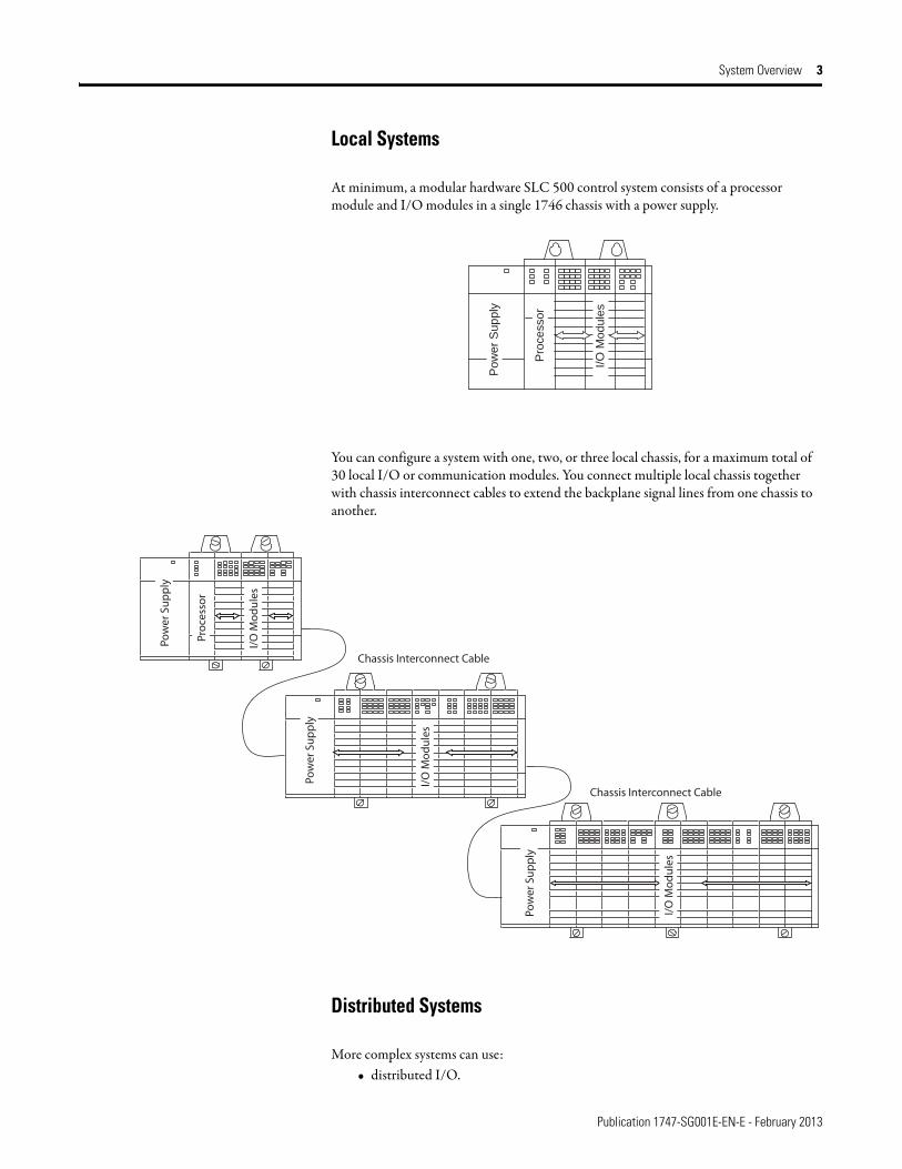
System Overview 3
Local Systems
At minimum, a modular hardware SLC 500 control system consists of a processor module and I/O modules in a single 1746 chassis with a power supply.
You can configure a system with one, two, or three local chassis, for a maximum total of 30 local I/O or communication modules. You connect multiple local chassis together with chassis interconnect cables to extend the backplane signal lines from one chassis to another.
Distributed Systems
More complex systems can use:• distributed I/O.
Po
we
r S
up
ply
Pro
ce
sso
r
I/O
Mo
du
les
Pow
er S
up
ply
Pro
cess
or
I/O
Mo
du
les
Pow
er S
up
ply
I/O
Mo
du
les
I/O
Mo
du
les
Chassis Interconnect Cable
Chassis Interconnect Cable
Pow
er S
up
ply
Publication 1747-SG001E-EN-E - February 2013
4 System Overview
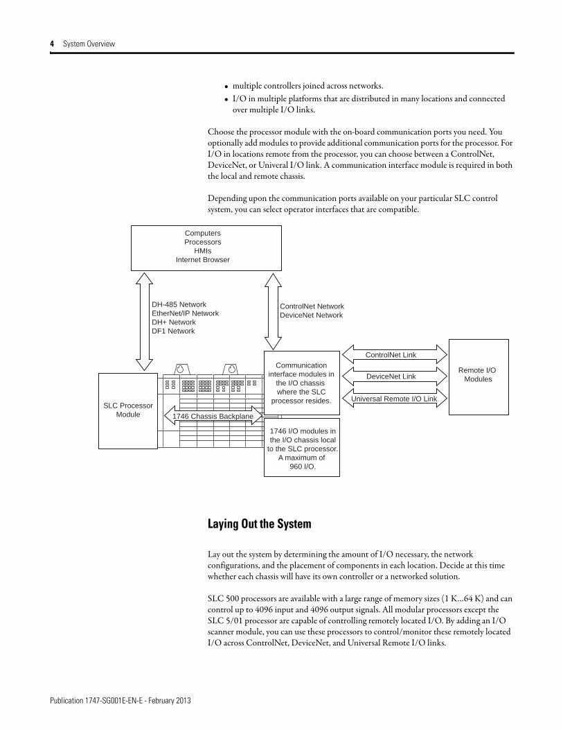
• multiple controllers joined across networks.• I/O in multiple platforms that are distributed in many locations and connected
over multiple I/O links.
Choose the processor module with the on-board communication ports you need. You optionally add modules to provide additional communication ports for the processor. For I/O in locations remote from the processor, you can choose between a ControlNet, DeviceNet, or Univeral I/O link. A communication interface module is required in both the local and remote chassis.
Depending upon the communication ports available on your particular SLC control system, you can select operator interfaces that are compatible.
Laying Out the System
Lay out the system by determining the amount of I/O necessary, the network configurations, and the placement of components in each location. Decide at this time whether each chassis will have its own controller or a networked solution.
SLC 500 processors are available with a large range of memory sizes (1 K…64 K) and can control up to 4096 input and 4096 output signals. All modular processors except the SLC 5/01 processor are capable of controlling remotely located I/O. By adding an I/O scanner module, you can use these processors to control/monitor these remotely located I/O across ControlNet, DeviceNet, and Universal Remote I/O links.
Computers
Processors
HMIs
Internet Browser
DH-485 Network
EtherNet/IP Network
DH+ Network
DF1 Network
ControlNet Network
DeviceNet Network
1746 Chassis Backplane
Communication
interface modules in
the I/O chassis
where the SLC
processor resides.
1746 I/O modules in
the I/O chassis local
to the SLC processor.
A maximum of
960 I/O.
ControlNet Link
DeviceNet Link
Universal Remote I/O Link
Remote I/O
Modules
SLC Processor
Module
Publication 1747-SG001E-EN-E - February 2013
System Overview 5
SLC 500 processors are single-slot modules that you place into the left-most slot of a 1746 I/O chassis. For I/O in a location remote from the processor, the I/O adapter is a single-slot module that you place in the left-most slot of the I/O chassis. SLC 500 modular systems provide separate power supplies which must be mounted directly on the left end of the 1746 I/O chassis.
The 1746 I/O chassis are designed for back-panel mounting and available in sizes of 4, 7, 10, or 13 module slots. The 1746 I/O modules are available in densities up to a maximum of 32 channels per module.
Communications
Evaluate what communications need to occur. Knowing your communications requirements will help you determine which processor and which communications devices your application might require.
An SLC processor communicates across the 1746 backplane to 1746 I/O modules in the same chassis in which the processor resides. Various models of SLC processors have various on-board ports for communication with other processors or computers. Also, separate modules are available to provide additional communication ports for communication with other processors, computers, and remotely located I/O.
Each processor has one or two built-in ports for either EtherNet/IP, DH+, DH-485, or RS-232 (DF1, ASCII, or DH-485 protocol) communication.
In addition to the on-board ports available with SLC processors, you have the option of providing another communication port for an SLC processor by adding a communication module.
Adapter modules for 1746 I/O are available for ControlNet and Universal Remote I/O links. An I/O adapter module in a chassis with I/O modules interfaces the I/O modules with the I/O link for communication with a scanner port for a processor at another location.
SLC 500 Common Specifications
The following specifications apply to all SLC 500 modular components unless noted.
Environmental Specifications
Attribute Value
Temperature, operating IEC 60068-2-1 (Test Ad, Operating Cold),IEC 60068-2-2 (Test Bd, Operating Dry Heat),IEC 60068-2-14 (Test Nb, Operating Thermal Shock):0…60 °C (32…140 °F)
Temperature, nonoperating IEC 60068-2-1 (Test Ab, Unpackaged Nonoperating Cold),IEC 60068-2-2 (Test Bb, Unpackaged Nonoperating Dry Heat),IEC 60068-2-14 (Test Na, Unpackaged Nonoperating Thermal Shock):-40…85 °C (-40…185 °F)
Relative humidity IEC 60068-2-30 (Test Db, Unpackaged Damp Heat):5…95% without condensation

Publication 1747-SG001E-EN-E - February 2013
6 System Overview
Vibration, operating IEC 60068-2-6 (Test Fc, Operating):1 g @ 5…2000 Hz
Vibration, nonoperating 2.5 g @ 5…2000 Hz
Shock, operating 30 g (3 pulses, 11 ms) – for all modules except relay contact10 g (3 pulses, 11 ms) – for relay contact modules 1746-OWx and 1746-IOx combo
Shock, nonoperating 50 g, 3 pulses, 11 ms
Free fall (drop test) Portable, 2.268 kg (5 lb) or less @ 0.762 m (30 in.), six dropsPortable, 2.268 kg (5 lb) or less @ 0.1016 m (4 in.), three flat drops
Isolation voltage Isolation between communication circuits: 500V DCIsolation between backplane and I/O: 1500V AC
Certifications
Certifications when product is marked(1)
(1) See the Product Certification link at http://www.rockwellautomation.com/products/certification/ for Declarations of Conformity, Certificates, and other certification details.
Value
UL UL Listed for Class I, Division 2 Group A,B,C,D Hazardous Locations. See UL File E10314.
c-UL UL Listed for Class I, Division 2 Group A,B,C,D Hazardous Locations, certified for Canada. See UL File E10314.
CE European Union 2004/108/EC EMC Directive, compliant with:EN 61000-6-2; Industrial ImmunityEN 61000-6-4; Industrial EmissionsEN 61131-2; Programmable Controllers (Clause 8, Zone A & B)
European Union 2006/95/EC LVD, compliant with:EN 61131-2; Programmable Controllers (Clause 11)
C-Tick Australian Radiocommunications Act, compliant with:AS/NZS CISPR 11; Industrial Emissions
KC Korean Registration of Broadcasting and Communications Equipment, compliant with: Article 58-2 of Radio Waves Act, Clause 3
Environmental Specifications
Attribute Value
Publication 1747-SG001E-EN-E - February 2013
System Overview 7
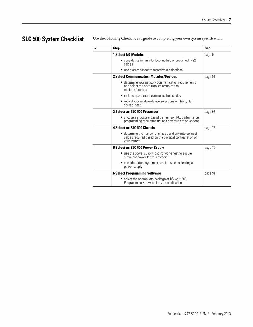
SLC 500 System Checklist Use the following Checklist as a guide to completing your own system specification.
✓ Step See
1 Select I/O Modules
• consider using an interface module or pre-wired 1492 cables
• use a spreadsheet to record your selections
page 9
2 Select Communication Modules/Devices
• determine your network communication requirements and select the necessary communication modules/devices
• include appropriate communication cables
• record your module/device selections on the system spreadsheet
page 51
3 Select an SLC 500 Processor
• choose a processor based on memory, I/O, performance, programming requirements, and communication options
page 69
4 Select an SLC 500 Chassis
• determine the number of chassis and any interconnect cables required based on the physical configuration of your system
page 75
5 Select an SLC 500 Power Supply
• use the power supply loading worksheet to ensure sufficient power for your system
• consider future system expansion when selecting a power supply
page 79
6 Select Programming Software
• select the appropriate package of RSLogix 500 Programming Software for your application
page 91

Publication 1747-SG001E-EN-E - February 2013
8 System Overview
Notes:
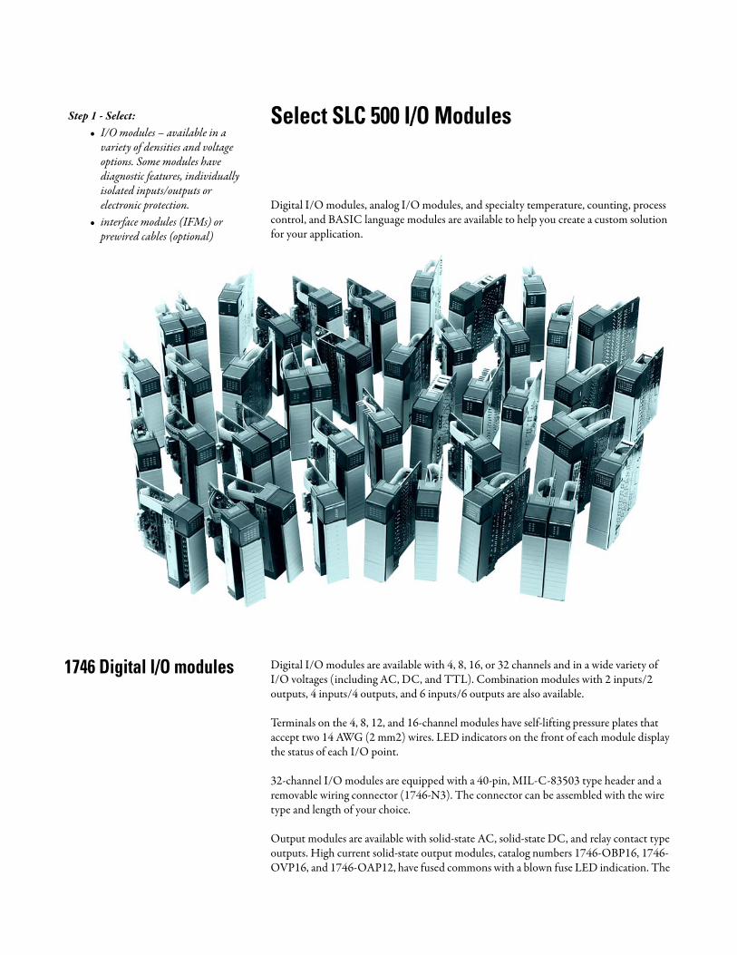
Select SLC 500 I/O Modules
Digital I/O modules, analog I/O modules, and specialty temperature, counting, process control, and BASIC language modules are available to help you create a custom solution for your application.
1746 Digital I/O modules Digital I/O modules are available with 4, 8, 16, or 32 channels and in a wide variety of I/O voltages (including AC, DC, and TTL). Combination modules with 2 inputs/2 outputs, 4 inputs/4 outputs, and 6 inputs/6 outputs are also available.
Terminals on the 4, 8, 12, and 16-channel modules have self-lifting pressure plates that accept two 14 AWG (2 mm2) wires. LED indicators on the front of each module display the status of each I/O point.
32-channel I/O modules are equipped with a 40-pin, MIL-C-83503 type header and a removable wiring connector (1746-N3). The connector can be assembled with the wire type and length of your choice.
Output modules are available with solid-state AC, solid-state DC, and relay contact type outputs. High current solid-state output modules, catalog numbers 1746-OBP16, 1746- OVP16, and 1746-OAP12, have fused commons with a blown fuse LED indication. The
Step 1 - Select:• I/O modules – available in a
variety of densities and voltage options. Some modules have diagnostic features, individually isolated inputs/outputs or electronic protection.
• interface modules (IFMs) or prewired cables (optional)

Publication 1747-SG001E-EN-E - February 2013
10 Select SLC 500 I/O Modules
1746-OB16E, 1746-OB6EI, and 1746-OB32E modules provide electronic protection from short circuit and overload conditions.
Wiring of 16 and 32-channel modules can also be accomplished with a bulletin 1492 interface module and pre-wired cable. All 16-channel I/O modules and catalog numbers 1746-OX8, 1746-OBP8, 1746-OAP12, 1746-IO12 are equipped with color-coded removable terminal blocks.
Digital I/O Module Overview
Catalog Number Voltage Category I/O Points Description For Detailed Specifications, See
DC Modules
1746-IB8 24V DC 8 Current Sinking DC Input Module Sinking DC Input Modulespage 11
1746-IB16 24V DC 16 Current Sinking DC Input Module
1746-IB32 24V DC 32 Current Sinking DC Input Module
1746-ITB16 24V DC 16 Fast Response DC Sinking Input Module
1746-IC16 48V DC 16 Current Sinking DC Input Module
1746-IH16 125V DC 16 Current Sinking DC Input Module
1746-IV8 24V DC 8 Current Sourcing DC Input Module Sourcing DC Input Modulespage 12
1746-IV16 24V DC 16 Current Sourcing DC Input Module
1746-IV32 24V DC 32 Current Sourcing DC Input Module
1746-ITV16 24V DC 16 Fast Response DC Sourcing Input Module
1746-IG16(1) 5V DC 16 Current Sourcing TTL Input Module
1746-OB6EI 24V DC 6 Electronically Protected Isolated Sourcing DC Output Module
Sourcing DC Output Modulespage 13
1746-OB8 24V DC 8 Current Sourcing DC Output Module
1746-OB16 24V DC 16 Current Sourcing DC Output Module
1746-OB16E 24V DC 16 Electronically Protected Current Sourcing DC Output Module
1746-OB32 24V DC 32 Current Sourcing DC Output Module
1746-OB32E 24V DC 32 Electronically Protected Current Sourcing DC Output Module
1746-OBP8 24V DC 8 High Current Sourcing DC Output Module
1746-OBP16(2) 24V DC 16 High Current Sourcing DC Output Module
1746-OV8 24V DC 8 Current Sinking DC Output Module Sinking DC Output Modulespage 12
1746-OV16 24V DC 16 Current Sinking DC Output Module
1746-OV32 24V DC 32 Current Sinking DC Output Module
1746-OVP16(2) 24V DC 16 High Current Sinking DC Output Module
1746-OG16(1) 5V DC 16 Current Sinking TTL Output Module
AC Modules
Publication 1747-SG001E-EN-E - February 2013
Select SLC 500 I/O Modules 11
1746-IA4 100/120V AC 4 120V AC Input Module AC Input Modulespage 14
1746-IA8 100/120V AC 8 120V AC Input Module
1746-IA16 100/120V AC 16 120V AC Input Module
1746-IM4 200/240V AC 4 240V AC Input Module
1746-IM8 200/240V AC 8 240V AC Input Module
1746-IM16 200/240V AC 16 240V AC Input Module
1746-OA8 120/240V AC 8 120/240V AC Output Module AC Output Modulespage 15
1746-OA16 120/240V AC 16 120/240V AC Output Module
1746-OAP12(2) 120/240V AC 12 High Current 120/240V AC Output Module
AC/DC Modules
1746-IN16 24V AC/DC 16 24V AC/DC Input Module AC Input Modulespage 14
1746-OW4(2) AC/DC Relay 4 Relay (Hard Contact) Output Module Relay Output Modulespage 16
1746-OW8(2) AC/DC Relay 8 Relay (Hard Contact) Output Module
1746-OW16(2) AC/DC Relay Relay (Hard Contact) Output Module
1746-OX8(2) AC/DC Relay 8 Relay (Hard Contact) Output Module
1746-IO4(2) 120V ac (Inputs) 100/120V AC (Relay Contact Outputs)
2 In2 Out
Combination Input/Output Module Combination I/O Modulespage 17
1746-IO8(2) 120V AC (Inputs) 100/120V AC (Relay Contact Outputs)
Combination Input/Output Module
1746-IO12(2) 120V AC (Inputs) 100/120V AC (Relay Contact Outputs)
4 In4 Out
Combination Input/Output Module
1746-IO12DC 24V DC (Inputs) 100/120V AC (Relay Contact Outputs)
6 In6 Out
Combination Input/Output Module
(1) Not CE marked.
(2) Certified for Class 1, Division 2 hazardous location by C-UL only.
Digital I/O Module Overview
Catalog Number Voltage Category I/O Points Description For Detailed Specifications, See
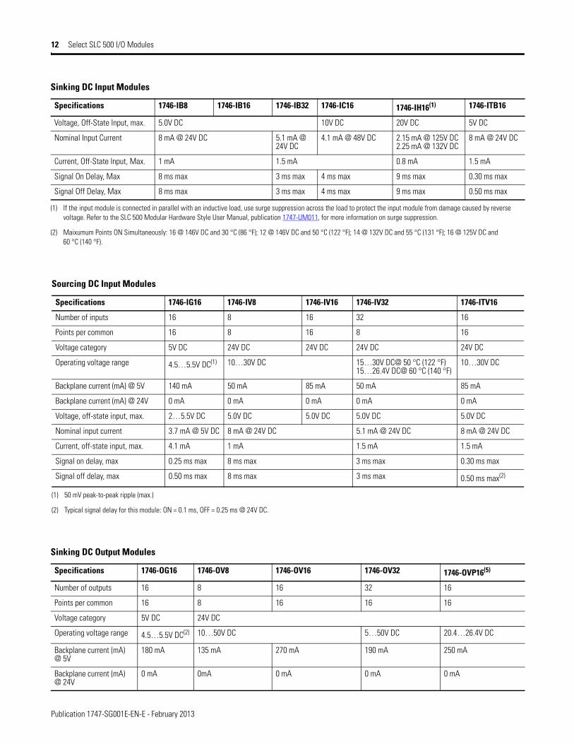
Sinking DC Input Modules
Specifications 1746-IB8 1746-IB16 1746-IB32 1746-IC16 1746-IH16(1) 1746-ITB16
Number of Inputs 8 16 32 32 16 16
Points Per Common 8 16 8 8 16 16
Voltage Category 24V DC 48V DC 125V DC 24V DC
Operating Voltage Range 10…30V DC 15…30V DC @ 50 °C (122 °F)15…26.4V DC @ 60 °C (140 °F)
30…60V DC @ 55 °C (131 °F)30…55V DC @ 60 °C (140 °F)
90…146V DC(2) 10…30V DC
Backplane Current (mA) @ 5V 50 mA 50 mA 50 mA 50 mA
Backplane Current (mA) @ 24V 0 mA 0 mA 0 mA 0 mA 0 mA 0mA
Publication 1747-SG001E-EN-E - February 2013
12 Select SLC 500 I/O Modules
Voltage, Off-State Input, max. 5.0V DC 10V DC 20V DC 5V DC
Nominal Input Current 8 mA @ 24V DC 5.1 mA @ 24V DC
4.1 mA @ 48V DC 2.15 mA @ 125V DC2.25 mA @ 132V DC
8 mA @ 24V DC
Current, Off-State Input, Max. 1 mA 1.5 mA 0.8 mA 1.5 mA
Signal On Delay, Max 8 ms max 3 ms max 4 ms max 9 ms max 0.30 ms max
Signal Off Delay, Max 8 ms max 3 ms max 4 ms max 9 ms max 0.50 ms max
(1) If the input module is connected in parallel with an inductive load, use surge suppression across the load to protect the input module from damage caused by reverse voltage. Refer to the SLC 500 Modular Hardware Style User Manual, publication 1747-UM011, for more information on surge suppression.
(2) Maixumum Points ON Simultaneously: 16 @ 146V DC and 30 °C (86 °F); 12 @ 146V DC and 50 °C (122 °F); 14 @ 132V DC and 55 °C (131 °F); 16 @ 125V DC and 60 °C (140 °F).
Sinking DC Input Modules
Specifications 1746-IB8 1746-IB16 1746-IB32 1746-IC16 1746-IH16(1) 1746-ITB16
Sourcing DC Input Modules
Specifications 1746-IG16 1746-IV8 1746-IV16 1746-IV32 1746-ITV16
Number of inputs 16 8 16 32 16
Points per common 16 8 16 8 16
Voltage category 5V DC 24V DC 24V DC 24V DC 24V DC
Operating voltage range 4.5…5.5V DC(1) 10…30V DC 15…30V DC@ 50 °C (122 °F)15…26.4V DC@ 60 °C (140 °F)
10…30V DC
Backplane current (mA) @ 5V 140 mA 50 mA 85 mA 50 mA 85 mA
Backplane current (mA) @ 24V 0 mA 0 mA 0 mA 0 mA 0 mA
Voltage, off-state input, max. 2…5.5V DC 5.0V DC 5.0V DC 5.0V DC 5.0V DC
Nominal input current 3.7 mA @ 5V DC 8 mA @ 24V DC 5.1 mA @ 24V DC 8 mA @ 24V DC
Current, off-state input, max. 4.1 mA 1 mA 1.5 mA 1.5 mA
Signal on delay, max 0.25 ms max 8 ms max 3 ms max 0.30 ms max
Signal off delay, max 0.50 ms max 8 ms max 3 ms max 0.50 ms max(2)
(1) 50 mV peak-to-peak ripple (max.)
(2) Typical signal delay for this module: ON = 0.1 ms, OFF = 0.25 ms @ 24V DC.
Sinking DC Output Modules
Specifications 1746-OG16 1746-OV8 1746-OV16 1746-OV32 1746-OVP16(5)
Number of outputs 16 8 16 32 16
Points per common 16 8 16 16 16
Voltage category 5V DC 24V DC
Operating voltage range 4.5…5.5V DC(2) 10…50V DC 5…50V DC 20.4…26.4V DC
Backplane current (mA) @ 5V
180 mA 135 mA 270 mA 190 mA 250 mA
Backplane current (mA) @ 24V
0 mA 0mA 0 mA 0 mA 0 mA

Publication 1747-SG001E-EN-E - February 2013
Select SLC 500 I/O Modules 13
Voltage drop, on-state output, max.
— 1.2V @ 1.0 A 1.2V @ 0.5 A 1.2V @ 0.5 A 1.0 V @ 1.0 A
Load current, min. 0.15 mA 1 mA 1 mA 1 mA 1 mA
Leakage current, off-state output,max
0.1 mA 1 mA(3) 1 mA(3) 1 mA(3) 1 mA(3)
Signal On Delay, max (resistive load)
0.25 ms 0.1 ms 0.1 ms 0.1 ms 0.1 ms(6)
Signal Off Delay, max (resistive load)
0.50 ms 1.0 ms 1.0 ms 1.0 ms 1.0 ms
Continuous current per module
N/A 8.0 A @ 30 °C (86 °F)4.0 A @ 60 °C (140 °F)
8.0 A @ 0…60 °C(32…140 °F)
6.4 A @ 0…60 °C(32…140 °F)
Continuous current per point
24 mA 1.0 A @ 30 °C (86 °F)0.5 A @ 60 °C (140 °F)
0.50 A @30 °C (86 °F)0.25 A @60 °C (140 °F)(4)
0.50 A @ 30 °C0.25 A @ 60 °C
1.5 A @ 30 °C (86 °F)1.0 A @ 60 °C (140 °F)(7)
Surge current per point for 10 ms(1)
N/A 3.0 A 1.0 A @ 30 °C (86 °F)1.0 A @ 60 °C (140 °F)
4.0 A(8)
(1) Repeatability is once every 1 s @ 30 °C (86 °F). Repeatability is once every 2 s @ 60 °C (140 °F).
(2) 50 mV peak to peak ripple, max.
(3) To limit the effects of leakage current through solid-state outputs, a loading resistor can be connected in parallel with your load. For transistor outputs, 24V DC operation, use a 5.6 K Ω, 1/2 W resistor.
(4) Recommended surge suppression: For transistor outputs, when switching 24V DC inductive loads, use a 1N4004 diode reverse-wired across the load. Refer to the SLC 500 Modular Hardware Style User Manual, publication 1747-UM011, for more information on surge suppression.
(5) The 1746-OVP16 module features a fused common and blown fuse LED indicator.
(6) Fast turn-off modules provide fast OFF delay for inductive loads. Fast turn-off delay for inductive loads is accomplished with surge suppressors on this module. A suppressor at the load is not needed unless another contact is connected in series. If this is the case, a 1N4004 diode should be reverse wired across the load. This defeats the fast turn-off feature. Comparative OFF delay times for 1746-OB8, 1746-OV8 and fast turn-off modules, when switching Bulletin 100-B110 (24 W sealed) contactor, are: 1746-OB8 and 1746-OV8 modules OFF delay = 152 ms; fast turnoff modules OFF delay = 47 ms.
(7) Fast off-delay for inductive loads is accomplished with surge suppressors on the 1746-IB6EI and 1746-OBP8 series B and later, 1746-OB16E series B and later, 1746-OBP16 and 1746-OVP16 modules. A suppressor at the load is not needed unless another contact is connected in series. If this is the case, a 1N4004 diode should be reverse-wired across the load. This defeats the fast turn-off feature.
(8) Surge current = 32 A per module for 10 ms.
Sinking DC Output Modules
Specifications 1746-OG16 1746-OV8 1746-OV16 1746-OV32 1746-OVP16(5)
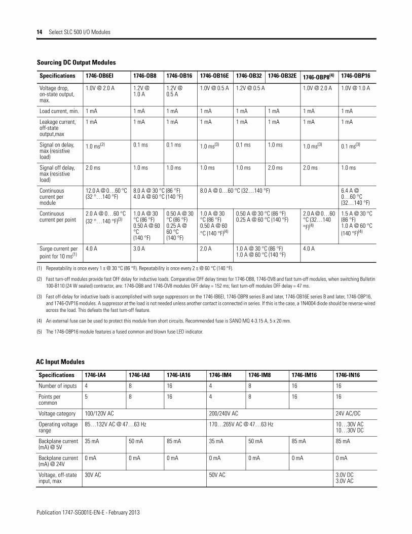
Sourcing DC Output Modules
Specifications 1746-OB6EI 1746-OB8 1746-OB16 1746-OB16E 1746-OB32 1746-OB32E 1746-OBP8(4) 1746-OBP16
Number of outputs 6 Electronically Protected
8 16 16 Electronically Protected
32 32 Electronically Protected
8 16(5)
Points per common
Individually isolated
8 16 16 16 16 4 16
Voltage category 24V DC
Operating voltage range
10 …30V DC 10…50V DC 10…30V DC 5…50V DC 10…30V DC 20.4…26.4V DC
Backplane current (mA) @ 5V
46 mA 135 mA 280 mA 135 mA 190 mA 135 mA 250 mA
Backplane current (mA) @ 24V
0 mA 0 mA 0 mA 0 mA 0 mA 0 mA 0 mA 0 mA
Publication 1747-SG001E-EN-E - February 2013
14 Select SLC 500 I/O Modules
Voltage drop, on-state output, max.
1.0V @ 2.0 A 1.2V @ 1.0 A
1.2V @ 0.5 A
1.0V @ 0.5 A 1.2V @ 0.5 A 1.0V @ 2.0 A 1.0V @ 1.0 A
Load current, min. 1 mA 1 mA 1 mA 1 mA 1 mA 1 mA 1 mA 1 mA
Leakage current, off-state output,max
1 mA 1 mA 1 mA 1 mA 1 mA 1 mA 1 mA 1 mA
Signal on delay, max (resistive load)
1.0 ms(2) 0.1 ms 0.1 ms 1.0 ms(3) 0.1 ms 1.0 ms 1.0 ms(3) 0.1 ms(3)
Signal off delay, max (resistive load)
2.0 ms 1.0 ms 1.0 ms 1.0 ms 1.0 ms 2.0 ms 2.0 ms 1.0 ms
Continuous current per module
12.0 A @ 0…60 °C (32 °…140 °F)
8.0 A @ 30 °C (86 °F)4.0 A @ 60 °C (140 °F)
8.0 A @ 0…60 °C (32…140 °F) 6.4 A @ 0…60 °C (32…140 °F)
Continuous current per point
2.0 A @ 0…60 °C (32 °…140 °F)(3)
1.0 A @ 30 °C (86 °F)0.50 A @ 60 °C (140 °F)
0.50 A @ 30 °C (86 °F)0.25 A @ 60 °C (140 °F)
1.0 A @ 30 °C (86 °F)0.50 A @ 60 °C (140 °F)(4)
0.50 A @ 30 °C (86 °F)0.25 A @ 60 °C (140 °F)
2.0 A @ 0…60 °C (32…140 °F)(4)
1.5 A @ 30 °C (86 °F) 1.0 A @ 60 °C (140 °F)(4)
Surge current per point for 10 ms(1)
4.0 A 3.0 A 2.0 A 1.0 A @ 30 °C (86 °F)1.0 A @ 60 °C (140 °F)
4.0 A
(1) Repeatability is once every 1 s @ 30 °C (86 °F). Repeatability is once every 2 s @ 60 °C (140 °F).
(2) Fast turn-off modules provide fast OFF delay for inductive loads. Comparative OFF delay times for 1746-OB8, 1746-OV8 and fast turn-off modules, when switching Bulletin 100-B110 (24 W sealed) contractor, are: 1746-OB8 and 1746-OV8 modules OFF delay = 152 ms; fast turn-off modules OFF delay = 47 ms.
(3) Fast off-delay for inductive loads is accomplished with surge suppressors on the 1746-IB6EI, 1746-OBP8 series B and later, 1746-OB16E series B and later, 1746-OBP16, and 1746-OVP16 modules. A suppressor at the load is not needed unless another contact is connected in series. If this is the case, a 1N4004 diode should be reverse-wired across the load. This defeats the fast turn-off feature.
(4) An external fuse can be used to protect this module from short circuits. Recommended fuse is SANO MQ 4-3.15 A, 5 x 20 mm.
(5) The 1746-OBP16 module features a fused common and blown fuse LED indicator.
Sourcing DC Output Modules
Specifications 1746-OB6EI 1746-OB8 1746-OB16 1746-OB16E 1746-OB32 1746-OB32E 1746-OBP8(4) 1746-OBP16
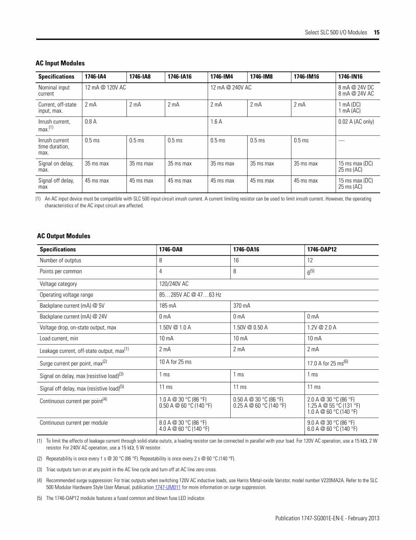
AC Input Modules
Specifications 1746-IA4 1746-IA8 1746-IA16 1746-IM4 1746-IM8 1746-IM16 1746-IN16
Number of inputs 4 8 16 4 8 16 16
Points per common
5 8 16 4 8 16 16
Voltage category 100/120V AC 200/240V AC 24V AC/DC
Operating voltage range
85…132V AC @ 47…63 Hz 170…265V AC @ 47…63 Hz 10…30V AC10…30V DC
Backplane current (mA) @ 5V
35 mA 50 mA 85 mA 35 mA 50 mA 85 mA 85 mA
Backplane current (mA) @ 24V
0 mA 0 mA 0 mA 0 mA 0 mA 0 mA 0 mA
Voltage, off-state input, max
30V AC 50V AC 3.0V DC3.0V AC
Publication 1747-SG001E-EN-E - February 2013
Select SLC 500 I/O Modules 15
Nominal input current
12 mA @ 120V AC 12 mA @ 240V AC 8 mA @ 24V DC8 mA @ 24V AC
Current, off-state input, max.
2 mA 2 mA 2 mA 2 mA 2 mA 2 mA 1 mA (DC)1 mA (AC)
Inrush current, max.(1)
0.8 A 1.6 A 0.02 A (AC only)
Inrush current time duration, max.
0.5 ms 0.5 ms 0.5 ms 0.5 ms 0.5 ms 0.5 ms —
Signal on delay, max.
35 ms max 35 ms max 35 ms max 35 ms max 35 ms max 35 ms max 15 ms max (DC)25 ms (AC)
Signal off delay, max
45 ms max 45 ms max 45 ms max 45 ms max 45 ms max 45 ms max 15 ms max (DC)25 ms (AC)
(1) An AC input device must be compatible with SLC 500 input circuit inrush current. A current limiting resistor can be used to limit inrush current. However, the operating characteristics of the AC input circuit are affected.
AC Input Modules
Specifications 1746-IA4 1746-IA8 1746-IA16 1746-IM4 1746-IM8 1746-IM16 1746-IN16
AC Output Modules
Specifications 1746-OA8 1746-OA16 1746-OAP12
Number of outptus 8 16 12
Points per common 4 8 6(5)
Voltage category 120/240V AC
Operating voltage range 85…265V AC @ 47…63 Hz
Backplane current (mA) @ 5V 185 mA 370 mA
Backplane current (mA) @ 24V 0 mA 0 mA 0 mA
Voltage drop, on-state output, max 1.50V @ 1.0 A 1.50V @ 0.50 A 1.2V @ 2.0 A
Load current, min 10 mA 10 mA 10 mA
Leakage current, off-state output, max(1) 2 mA 2 mA 2 mA
Surge current per point, max(2) 10 A for 25 ms 17.0 A for 25 ms(6)
Signal on delay, max (resistive load)(3) 1 ms 1 ms 1 ms
Signal off delay, max (resistive load)(5) 11 ms 11 ms 11 ms
Continuous current per point(4) 1.0 A @ 30 °C (86 °F)0.50 A @ 60 °C (140 °F)
0.50 A @ 30 °C (86 °F)0.25 A @ 60 °C (140 °F)
2.0 A @ 30 °C (86 °F)1.25 A @ 55 °C (131 °F)1.0 A @ 60 °C (140 °F)
Continuous current per module 8.0 A @ 30 °C (86 °F)4.0 A @ 60 °C (140 °F)
9.0 A @ 30 °C (86 °F)6.0 A @ 60 °C (140 °F)
(1) To limit the effects of leakage current through solid-state oututs, a loading resistor can be connected in parallel with your load. For 120V AC operation, use a 15 kΩ, 2 W resistor. For 240V AC operation, use a 15 kΩ, 5 W resistor.
(2) Repeatability is once every 1 s @ 30 °C (86 °F). Repeatability is once every 2 s @ 60 °C (140 °F).
(3) Triac outputs turn on at any point in the AC line cycle and turn off at AC line zero cross.
(4) Recommended surge suppression: For triac outputs when switching 120V AC inductive loads, use Harris Metal-oxide Varistor, model number V220MA2A. Refer to the SLC 500 Modular Hardware Style User Manual, publication 1747-UM011 for more information on surge suppression.
(5) The 1746-OAP12 module features a fused common and blown fuse LED indicator.
Publication 1747-SG001E-EN-E - February 2013
16 Select SLC 500 I/O Modules
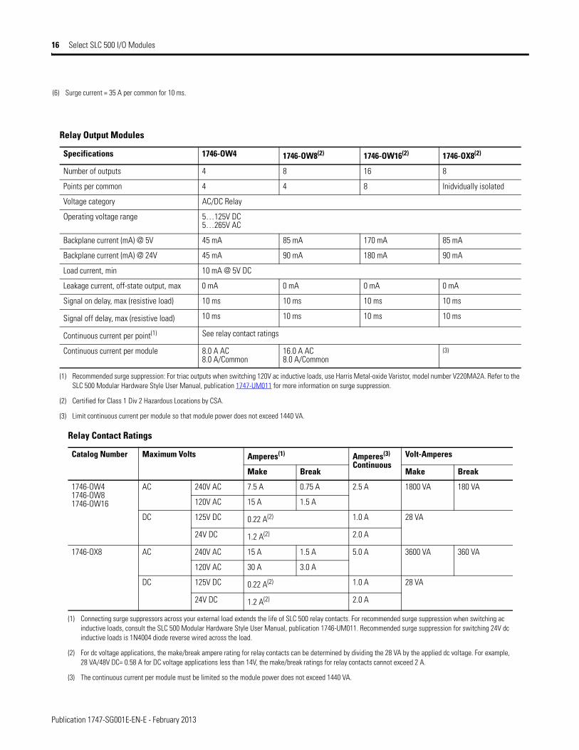
(6) Surge current = 35 A per common for 10 ms.
Relay Output Modules
Specifications 1746-OW4 1746-OW8(2) 1746-OW16(2) 1746-OX8(2)
Number of outputs 4 8 16 8
Points per common 4 4 8 Inidvidually isolated
Voltage category AC/DC Relay
Operating voltage range 5…125V DC5…265V AC
Backplane current (mA) @ 5V 45 mA 85 mA 170 mA 85 mA
Backplane current (mA) @ 24V 45 mA 90 mA 180 mA 90 mA
Load current, min 10 mA @ 5V DC
Leakage current, off-state output, max 0 mA 0 mA 0 mA 0 mA
Signal on delay, max (resistive load) 10 ms 10 ms 10 ms 10 ms
Signal off delay, max (resistive load) 10 ms 10 ms 10 ms 10 ms
Continuous current per point(1) See relay contact ratings
Continuous current per module 8.0 A AC8.0 A/Common
16.0 A AC8.0 A/Common
(3)
(1) Recommended surge suppression: For triac outputs when switching 120V ac inductive loads, use Harris Metal-oxide Varistor, model number V220MA2A. Refer to the SLC 500 Modular Hardware Style User Manual, publication 1747-UM011 for more information on surge suppression.
(2) Certified for Class 1 Div 2 Hazardous Locations by CSA.
(3) Limit continuous current per module so that module power does not exceed 1440 VA.
Relay Contact Ratings
Catalog Number Maximum Volts Amperes(1) Amperes(3)
ContinuousVolt-Amperes
Make Break Make Break
1746-OW41746-OW81746-OW16
AC 240V AC 7.5 A 0.75 A 2.5 A 1800 VA 180 VA
120V AC 15 A 1.5 A
DC 125V DC 0.22 A(2) 1.0 A 28 VA
24V DC 1.2 A(2) 2.0 A
1746-OX8 AC 240V AC 15 A 1.5 A 5.0 A 3600 VA 360 VA
120V AC 30 A 3.0 A
DC 125V DC 0.22 A(2) 1.0 A 28 VA
24V DC 1.2 A(2) 2.0 A
(1) Connecting surge suppressors across your external load extends the life of SLC 500 relay contacts. For recommended surge suppression when switching ac inductive loads, consult the SLC 500 Modular Hardware Style User Manual, publication 1746-UM011. Recommended surge suppression for switching 24V dc inductive loads is 1N4004 diode reverse wired across the load.
(2) For dc voltage applications, the make/break ampere rating for relay contacts can be determined by dividing the 28 VA by the applied dc voltage. For example, 28 VA/48V DC= 0.58 A for DC voltage applications less than 14V, the make/break ratings for relay contacts cannot exceed 2 A.
(3) The continuous current per module must be limited so the module power does not exceed 1440 VA.
Publication 1747-SG001E-EN-E - February 2013
Select SLC 500 I/O Modules 17
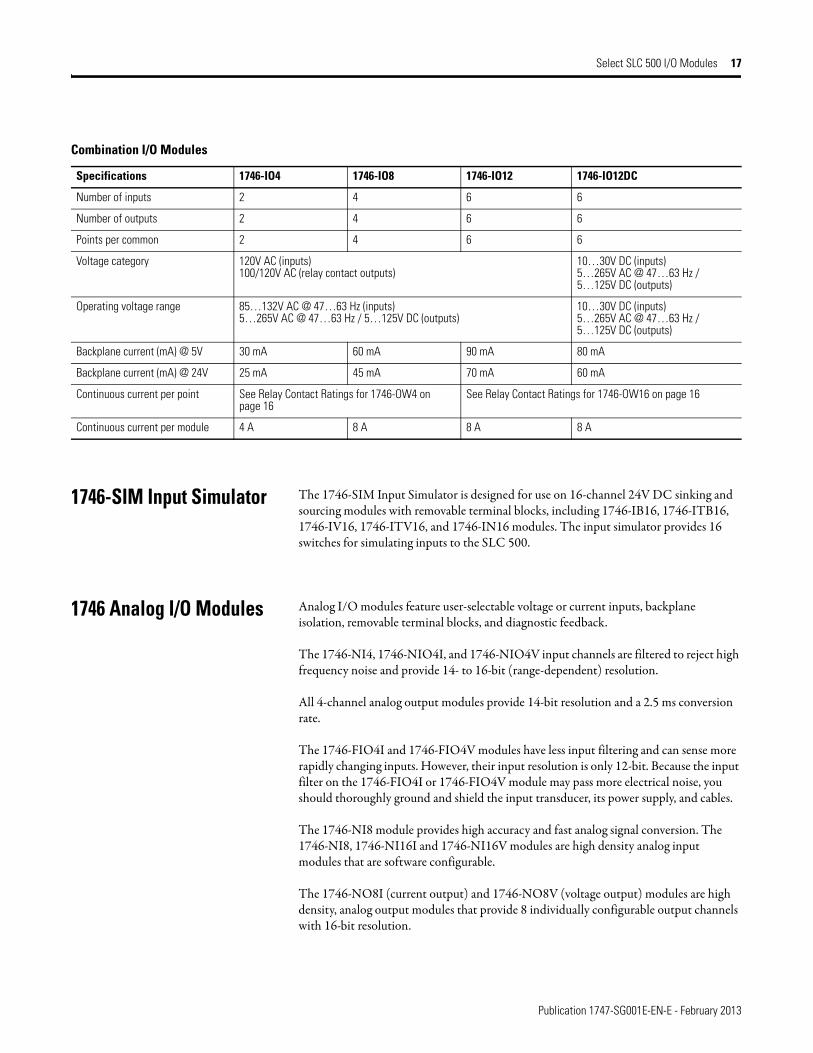
1746-SIM Input Simulator The 1746-SIM Input Simulator is designed for use on 16-channel 24V DC sinking and sourcing modules with removable terminal blocks, including 1746-IB16, 1746-ITB16, 1746-IV16, 1746-ITV16, and 1746-IN16 modules. The input simulator provides 16 switches for simulating inputs to the SLC 500.
1746 Analog I/O Modules Analog I/O modules feature user-selectable voltage or current inputs, backplane isolation, removable terminal blocks, and diagnostic feedback.
The 1746-NI4, 1746-NIO4I, and 1746-NIO4V input channels are filtered to reject high frequency noise and provide 14- to 16-bit (range-dependent) resolution.
All 4-channel analog output modules provide 14-bit resolution and a 2.5 ms conversion rate.
The 1746-FIO4I and 1746-FIO4V modules have less input filtering and can sense more rapidly changing inputs. However, their input resolution is only 12-bit. Because the input filter on the 1746-FIO4I or 1746-FIO4V module may pass more electrical noise, you should thoroughly ground and shield the input transducer, its power supply, and cables.
The 1746-NI8 module provides high accuracy and fast analog signal conversion. The 1746-NI8, 1746-NI16I and 1746-NI16V modules are high density analog input modules that are software configurable.
The 1746-NO8I (current output) and 1746-NO8V (voltage output) modules are high density, analog output modules that provide 8 individually configurable output channels with 16-bit resolution.
Combination I/O Modules
Specifications 1746-IO4 1746-IO8 1746-IO12 1746-IO12DC
Number of inputs 2 4 6 6
Number of outputs 2 4 6 6
Points per common 2 4 6 6
Voltage category 120V AC (inputs)100/120V AC (relay contact outputs)
10…30V DC (inputs)5…265V AC @ 47…63 Hz / 5…125V DC (outputs)
Operating voltage range 85…132V AC @ 47…63 Hz (inputs)5…265V AC @ 47…63 Hz / 5…125V DC (outputs)
10…30V DC (inputs)5…265V AC @ 47…63 Hz / 5…125V DC (outputs)
Backplane current (mA) @ 5V 30 mA 60 mA 90 mA 80 mA
Backplane current (mA) @ 24V 25 mA 45 mA 70 mA 60 mA
Continuous current per point See Relay Contact Ratings for 1746-OW4 on page 16
See Relay Contact Ratings for 1746-OW16 on page 16
Continuous current per module 4 A 8 A 8 A 8 A
Publication 1747-SG001E-EN-E - February 2013
18 Select SLC 500 I/O Modules
4-Channel Analog I/O Modules
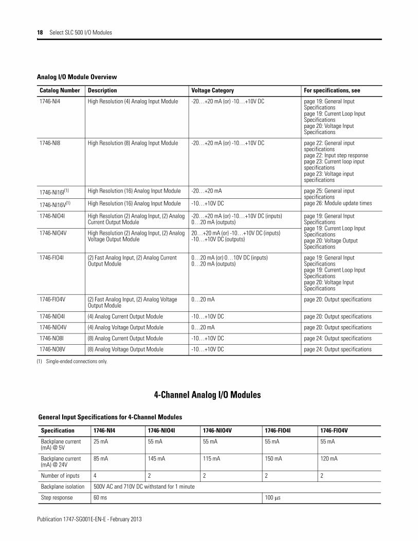
Analog I/O Module Overview
Catalog Number Description Voltage Category For specifications, see
1746-NI4 High Resolution (4) Analog Input Module -20…+20 mA (or) -10…+10V DC page 19: General Input Specificationspage 19: Current Loop Input Specificationspage 20: Voltage Input Specifications
1746-NI8 High Resolution (8) Analog Input Module -20…+20 mA (or) -10…+10V DC page 22: General input specificationspage 22: Input step responsepage 23: Current loop input specificationspage 23: Voltage input specifications
1746-NI16I(1) High Resolution (16) Analog Input Module -20…+20 mA page 25: General input specificationspage 26: Module update times1746-NI16V(1) High Resolution (16) Analog Input Module -10…+10V DC
1746-NIO4I High Resolution (2) Analog Input, (2) Analog Current Output Module
-20…+20 mA (or) -10…+10V DC (inputs) 0…20 mA (outputs)
page 19: General Input Specificationspage 19: Current Loop Input Specificationspage 20: Voltage Output Specifications
1746-NIO4V High Resolution (2) Analog Input, (2) Analog Voltage Output Module
20…+20 mA (or) -10…+10V DC (inputs) -10…+10V DC (outputs)
1746-FIO4I (2) Fast Analog Input, (2) Analog Current Output Module
0…20 mA (or) 0…10V DC (inputs)0…20 mA (outputs)
page 19: General Input Specificationspage 19: Current Loop Input Specificationspage 20: Voltage Input Specifications
1746-FIO4V (2) Fast Analog Input, (2) Analog Voltage Output Module
0…20 mA page 20: Output specifications
1746-NIO4I (4) Analog Current Output Module -10…+10V DC page 20: Output specifications
1746-NIO4V (4) Analog Voltage Output Module 0…20 mA page 20: Output specifications
1746-NO8I (8) Analog Current Output Module -10…+10V DC page 24: Output specifications
1746-NO8V (8) Analog Voltage Output Module -10…+10V DC page 24: Output specifications
(1) Single-ended connections only.
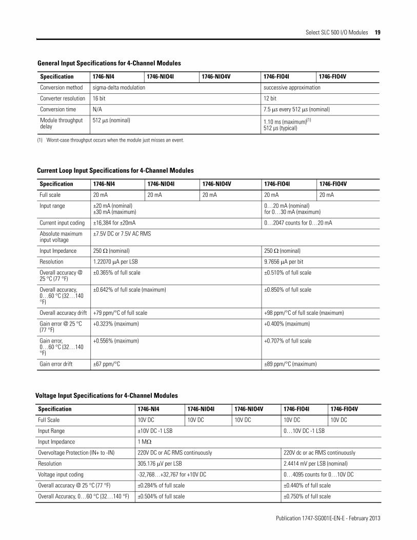
General Input Specifications for 4-Channel Modules
Specification 1746-NI4 1746-NIO4I 1746-NIO4V 1746-FIO4I 1746-FIO4V
Backplane current (mA) @ 5V
25 mA 55 mA 55 mA 55 mA 55 mA
Backplane current (mA) @ 24V
85 mA 145 mA 115 mA 150 mA 120 mA
Number of inputs 4 2 2 2 2
Backplane isolation 500V AC and 710V DC withstand for 1 minute
Step response 60 ms 100 μs
Publication 1747-SG001E-EN-E - February 2013
Select SLC 500 I/O Modules 19
Conversion method sigma-delta modulation successive approximation
Converter resolution 16 bit 12 bit
Conversion time N/A 7.5 μs every 512 μs (nominal)
Module throughput delay
512 μs (nominal) 1.10 ms (maximum)(1)
512 µs (typical)
(1) Worst-case throughput occurs when the module just misses an event.
General Input Specifications for 4-Channel Modules
Specification 1746-NI4 1746-NIO4I 1746-NIO4V 1746-FIO4I 1746-FIO4V
Current Loop Input Specifications for 4-Channel Modules
Specification 1746-NI4 1746-NIO4I 1746-NIO4V 1746-FIO4I 1746-FIO4V
Full scale 20 mA 20 mA 20 mA 20 mA 20 mA
Input range ±20 mA (nominal)±30 mA (maximum)
0…20 mA (nominal)for 0…30 mA (maximum)
Current input coding ±16,384 for ±20mA 0…2047 counts for 0…20 mA
Absolute maximum input voltage
±7.5V DC or 7.5V AC RMS
Input Impedance 250 Ω (nominal) 250 Ω (nominal)
Resolution 1.22070 μA per LSB 9.7656 μA per bit
Overall accuracy @ 25 °C (77 °F)
±0.365% of full scale ±0.510% of full scale
Overall accuracy, 0…60 °C (32…140 °F)
±0.642% of full scale (maximum) ±0.850% of full scale
Overall accuracy drift +79 ppm/°C of full scale +98 ppm/°C of full scale (maximum)
Gain error @ 25 °C (77 °F)
+0.323% (maximum) +0.400% (maximum)
Gain error,0…60 °C (32…140°F)
+0.556% (maximum) +0.707% of full scale
Gain error drift ±67 ppm/°C ±89 ppm/°C (maximum)
Voltage Input Specifications for 4-Channel Modules
Specification 1746-NI4 1746-NIO4I 1746-NIO4V 1746-FIO4I 1746-FIO4V
Full Scale 10V DC 10V DC 10V DC 10V DC 10V DC
Input Range ±10V DC -1 LSB 0…10V DC -1 LSB
Input Impedance 1 MΩ
Overvoltage Protection (IN+ to -IN) 220V DC or AC RMS continuously 220V dc or ac RMS continuously
Resolution 305.176 μV per LSB 2.4414 mV per LSB (nominal)
Voltage input coding -32,768…+32,767 for +10V DC 0…4095 counts for 0…10V DC
Overall accuracy @ 25 °C (77 °F) ±0.284% of full scale ±0.440% of full scale
Overall Accuracy, 0…60 °C (32…140 °F) ±0.504% of full scale ±0.750% of full scale

Publication 1747-SG001E-EN-E - February 2013
20 Select SLC 500 I/O Modules
Overall accuracy drift (maximum) +63 ppm/°C of full scale (maximum) +88 ppm/°C (maximum)
Gain error @ 25 °C (77 °F)
+0.263% (maximum) +0.323% of full scale
Gain error, 0…60 °C (32…140 °F) +0.461% (maximum) +0.530% of full scale
Gain error drift ±57 ppm/°C ±79 ppm?/°C
Voltage Input Specifications for 4-Channel Modules
Specification 1746-NI4 1746-NIO4I 1746-NIO4V 1746-FIO4I 1746-FIO4V
Output Specifications for 4-Channel Modules
Specification 1746-FIO4I 1746-NIO4I 1746-NO4I 1746-FIO4V 1746-NIO4V 1746-NO4V
Number of outputs 2 2 4 2 2 4
Backplane current (mA) @ 5V 55 mA 55 mA 55 mA 55 mA 55 mA 55 mA
Backplane current (mA) @ 24V 150 mA 145 mA 195 mA(1) 120 mA 115 mA 145 mA
Isolation voltage Tested @ 500V AC and 710V DC for 60 seconds
Full scale 21 mA 10V DC
Output range (normal) 0…20 mA -1 LSB ±10V DC -1 LSB
Output coding 0…32,764 for 0…21 mA -32,768…+32,764 for ±10V DC
Output resolution (per LSB) 2.56348 μA 1.22070 mV
Converter resolution 14-bit 14-bit
Conversion method R-2R ladder R-2R ladder
Step response 2.5 ms (5…95%) 2.5 ms (normal)
Load range 0…500 Ω 1K…? Ω
Load current, max N/A 10 mA
Overrange capability 5% (0…21 mA -1 LSB) N/A
Overall accuracy @ 25 °C (77 °F)
±0.298% of full scale ±0.208% of full scale
Overall Accuracy,0…60 °C (32…140 °F)
±0.541% of full scale ±0.384% of full scale
Overall accuracy drift, max ±70 ppm/°C of full scale ±0.384% of full scale
Gain error @ 25 °C (77 °F) ±298% of full scale ±208% of full scale
Gain Error, 0…60 °C (32…140 °F)
±516% of full scale ±374% of full scale
Gain error drift, max ±62 ppm/°C of full scale ±47 ppm/°C of full scale
(1) The 1746-NO4I and 1746-NO4V analog output modules have connections for user-supplied 24V dc power supplies. When external 24V DC power is used, the module only draws 5V DC current from the SLC backplane. If an external 24V DC power supply is required, the tolerance must be 24V ±10% (26.6…26.4V DC). The user power supplies for SLC 500 modular systems, 1746-P1, 1746-P2, 1746-P5, and 1746-P6 power supplies do not meet this specification.
Publication 1747-SG001E-EN-E - February 2013
Select SLC 500 I/O Modules 21
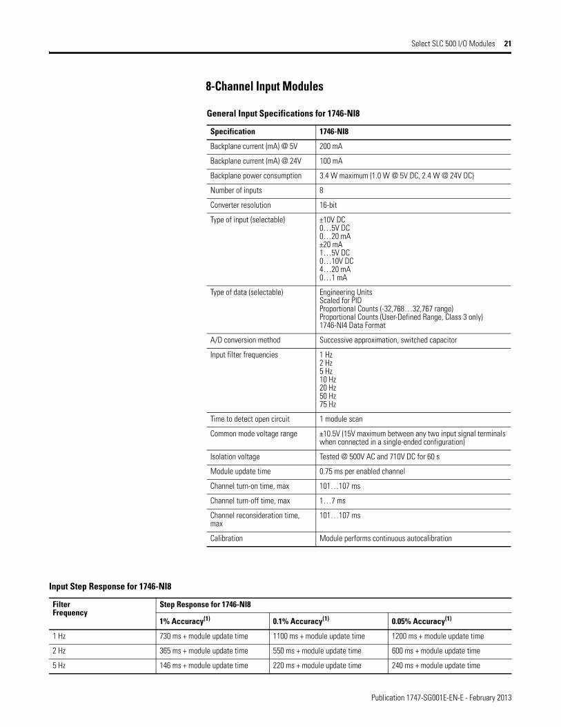
8-Channel Input Modules
General Input Specifications for 1746-NI8
Specification 1746-NI8
Backplane current (mA) @ 5V 200 mA
Backplane current (mA) @ 24V 100 mA
Backplane power consumption 3.4 W maximum (1.0 W @ 5V DC, 2.4 W @ 24V DC)
Number of inputs 8
Converter resolution 16-bit
Type of input (selectable) ±10V DC0…5V DC0…20 mA±20 mA1…5V DC0…10V DC4…20 mA0…1 mA
Type of data (selectable) Engineering UnitsScaled for PIDProportional Counts (-32,768…32,767 range)Proportional Counts (User-Defined Range, Class 3 only)1746-NI4 Data Format
A/D conversion method Successive approximation, switched capacitor
Input filter frequencies 1 Hz2 Hz5 Hz10 Hz20 Hz50 Hz75 Hz
Time to detect open circuit 1 module scan
Common mode voltage range ±10.5V (15V maximum between any two input signal terminals when connected in a single-ended configuration)
Isolation voltage Tested @ 500V AC and 710V DC for 60 s
Module update time 0.75 ms per enabled channel
Channel turn-on time, max 101…107 ms
Channel turn-off time, max 1…7 ms
Channel reconsideration time, max
101…107 ms
Calibration Module performs continuous autocalibration
Input Step Response for 1746-NI8
FilterFrequency
Step Response for 1746-NI8
1% Accuracy(1) 0.1% Accuracy(1) 0.05% Accuracy(1)
1 Hz 730 ms + module update time 1100 ms + module update time 1200 ms + module update time
2 Hz 365 ms + module update time 550 ms + module update time 600 ms + module update time
5 Hz 146 ms + module update time 220 ms + module update time 240 ms + module update time
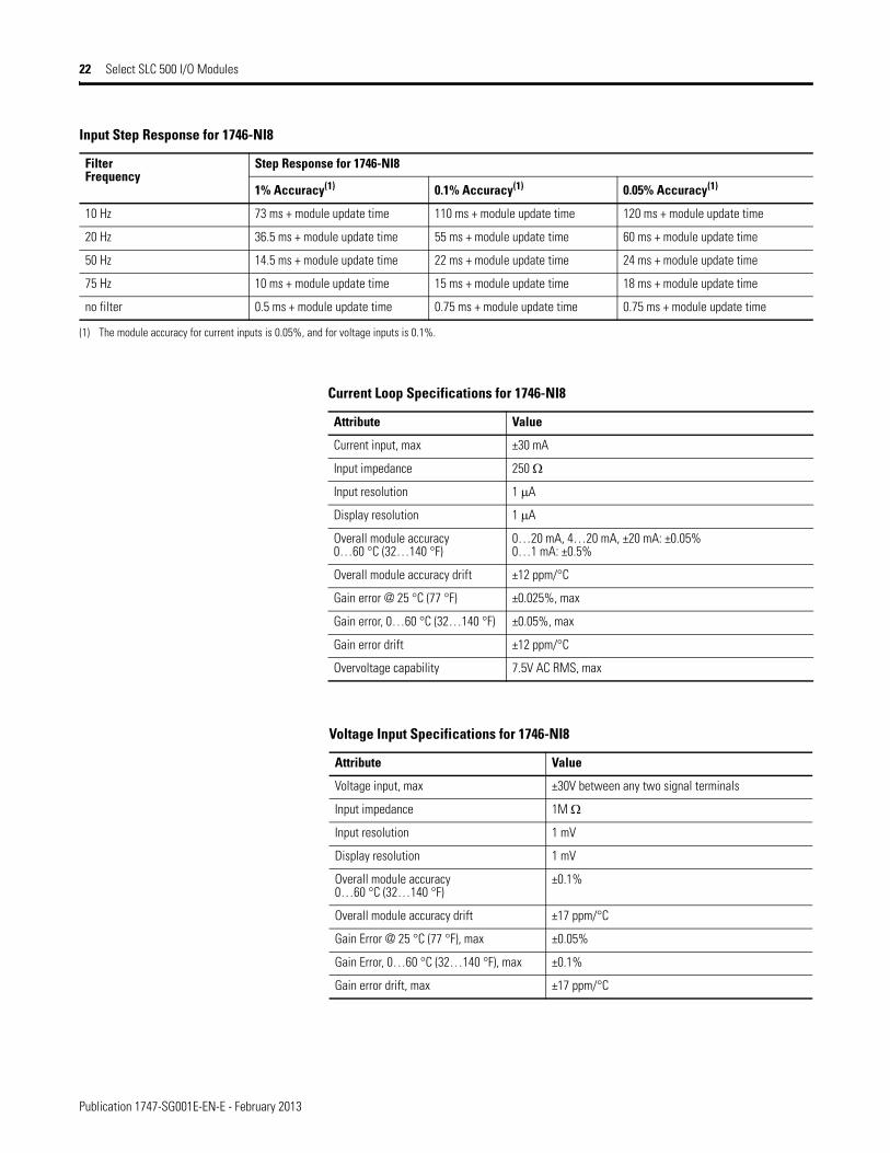
Publication 1747-SG001E-EN-E - February 2013
22 Select SLC 500 I/O Modules
10 Hz 73 ms + module update time 110 ms + module update time 120 ms + module update time
20 Hz 36.5 ms + module update time 55 ms + module update time 60 ms + module update time
50 Hz 14.5 ms + module update time 22 ms + module update time 24 ms + module update time
75 Hz 10 ms + module update time 15 ms + module update time 18 ms + module update time
no filter 0.5 ms + module update time 0.75 ms + module update time 0.75 ms + module update time
(1) The module accuracy for current inputs is 0.05%, and for voltage inputs is 0.1%.
Input Step Response for 1746-NI8
FilterFrequency
Step Response for 1746-NI8
1% Accuracy(1) 0.1% Accuracy(1) 0.05% Accuracy(1)
Current Loop Specifications for 1746-NI8
Attribute Value
Current input, max ±30 mA
Input impedance 250 Ω
Input resolution 1 μA
Display resolution 1 μA
Overall module accuracy 0…60 °C (32…140 °F)
0…20 mA, 4…20 mA, ±20 mA: ±0.05%0…1 mA: ±0.5%
Overall module accuracy drift ±12 ppm/°C
Gain error @ 25 °C (77 °F) ±0.025%, max
Gain error, 0…60 °C (32…140 °F) ±0.05%, max
Gain error drift ±12 ppm/°C
Overvoltage capability 7.5V AC RMS, max
Voltage Input Specifications for 1746-NI8
Attribute Value
Voltage input, max ±30V between any two signal terminals
Input impedance 1M Ω
Input resolution 1 mV
Display resolution 1 mV
Overall module accuracy0…60 °C (32…140 °F)
±0.1%
Overall module accuracy drift ±17 ppm/°C
Gain Error @ 25 °C (77 °F), max ±0.05%
Gain Error, 0…60 °C (32…140 °F), max ±0.1%
Gain error drift, max ±17 ppm/°C

Publication 1747-SG001E-EN-E - February 2013
Select SLC 500 I/O Modules 23
8-Channel Output Modules
Optional 24V DC power supply must be N.E.C. Class 2.
Output Specifications for 8-Channel Modules
Catalog Number 1746-NO8I 1746-NO8V
Backplane current (mA) @ 5V 120 mA 120 mA
Backplane current (mA) @ 24V 250 mA 160 mA(1)
(1) J4 jumper set to RACK; 0 mA at 24V dc with J4 Jumper set to EXT.
Backplane power consumption 5.6 W 5.6 W
Thermal dissipation, max 6.6 W 4.44 W
Isolation voltage Tested @ 500V DC Tested @ 500V DC
Number of outputs 8 8
Output type Current Voltage
Output range 0…21.5 mA ±10.25V DC
Output coding (proportional scaling) 0…32,767 -32,768…+32,767
Resolution 16-bit366 nA/count
16-bit320 μV/count
Non-Linearity 0.06% of full scale
DAC conversion method R-2R Ladder Network
Output step response 1 ms (0…95% of full scale)
Channel update time (typical) Class 1: 5 ms to update all 8 channelsClass 3: 10 ms to update all 8 channels
Load range 0…500 Ω 1 kΩ and greater
Load current N/A 10 mA, max
Output impedance Greater than 1M Ω Less than 1.0 Ω
Overrange capability 7.5% (21.5 mA) 2.5% (±10.25V)
Overall accuracy 0.1% of full scale @ 25 °C (77 °F)0.2% of full scale @ 60 °C (140 °F)
Overall accuracy drift, max ±33 ppm/°C of full scale
Gain error 0.08% of full scale @ 25 °C (77°F)0.15% of full scale @ 60 °C (140°F)
Gain error drift, max ±25 ppm/°C of full scale
Calibration Factory calibrated.
Publication 1747-SG001E-EN-E - February 2013
24 Select SLC 500 I/O Modules
16-Channel Input Modules
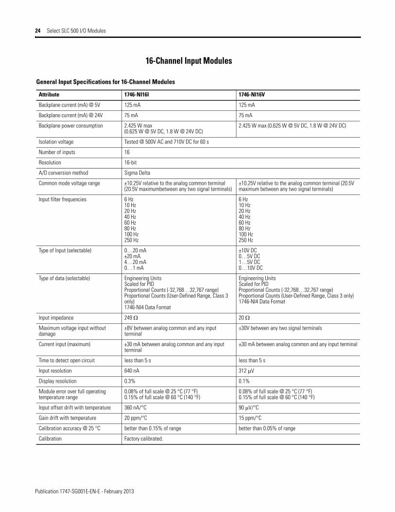
General Input Specifications for 16-Channel Modules
Attribute 1746-NI16I 1746-NI16V
Backplane current (mA) @ 5V 125 mA 125 mA
Backplane current (mA) @ 24V 75 mA 75 mA
Backplane power consumption 2.425 W max (0.625 W @ 5V DC, 1.8 W @ 24V DC)
2.425 W max (0.625 W @ 5V DC, 1.8 W @ 24V DC)
Isolation voltage Tested @ 500V AC and 710V DC for 60 s
Number of inputs 16
Resolution 16-bit
A/D conversion method Sigma Delta
Common mode voltage range ±10.25V relative to the analog common terminal (20.5V maximumbetween any two signal terminals)
±10.25V relative to the analog common terminal (20.5V maximum between any two signal terminals)
Input filter frequencies 6 Hz10 Hz20 Hz40 Hz60 Hz80 Hz100 Hz250 Hz
6 Hz10 Hz20 Hz40 Hz60 Hz80 Hz100 Hz250 Hz
Type of Input (selectable) 0…20 mA±20 mA4…20 mA0…1 mA
±10V DC0…5V DC1…5V DC0…10V DC
Type of data (selectable) Engineering UnitsScaled for PIDProportional Counts (-32,768…32,767 range)Proportional Counts (User-Defined Range, Class 3 only)1746-NI4 Data Format
Engineering UnitsScaled for PIDProportional Counts (-32,768…32,767 range)Proportional Counts (User-Defined Range, Class 3 only)1746-NI4 Data Format
Input impedance 249 Ω 20 Ω
Maximum voltage input without damage
±8V between analog common and any input terminal
±30V between any two signal terminals
Current input (maximum) ±30 mA between analog common and any input terminal
±30 mA between analog common and any input terminal
Time to detect open circuit less than 5 s less than 5 s
Input resolution 640 nA 312 μV
Display resolution 0.3% 0.1%
Module error over full operating temperature range
0.08% of full scale @ 25 °C (77 °F)0.15% of full scale @ 60 °C (140 °F)
0.08% of full scale @ 25 °C (77 °F)0.15% of full scale @ 60 °C (140 °F)
Input offset drift with temperature 360 nA/°C 90 μV/°C
Gain drift with temperature 20 ppm/°C 15 ppm/°C
Calibration accuracy @ 25 °C better than 0.15% of range better than 0.05% of range
Calibration Factory calibrated.

Publication 1747-SG001E-EN-E - February 2013
Select SLC 500 I/O Modules 25
Module update time is dependent on the number of channels enabled and the filter frequency, as illustrated in the table below.
Temperature Modules SLC 500 Thermocouple/mV Input Modules
All modules interface to thermocouple types J, K, T, E, R, S, B, and N, and also accept millivolt signals that standard analog modules are not able to detect. The 1746-INT4 module also interfaces with thermocouple types C and D.
All modules provide fully-integrated cold-junction compensation (CJC) to retain thermocouple input signal accuracy, a choice of input filter frequencies, as well as fault diagnostics and status LEDs.
Note: Block transfers are required in a remote I/O configuration, using a 1747-ASB module with a PLC.
Module Update Times for 1746-NI16I and 1746-NI16V
Module Update Time(1)
(1) Assuming all of the enabled channels have the filter frequency shown in the first column.
FilterFrequency
16 ChannelsEnabled
12 ChannelsEnabled
8 ChannelsEnabled
4 ChannelsEnabled
6 Hz 630 ms 473 ms 314 ms 7 ms
10 Hz 380 ms 285 ms 190 ms 4 ms
20 Hz 194 ms 145 ms 96 ms 4 ms
40 Hz 100 ms 75 ms 50 ms 4 ms
60 Hz 69 ms 52 ms 34 ms 4 ms
80 Hz 54 ms 39 ms 26 ms 4 ms
100 Hz 37 ms 27 ms 18 ms 4 ms
250 Hz 18 ms 13 ms 9 ms 4 ms
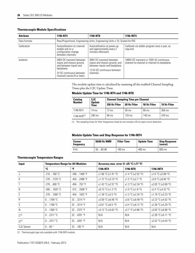
Thermocouple Module Specifications
Attribute 1746-NT4 1746-NT8 1746-INT4
Backplane current (mA) @ 5V 60 mA 120 mA 110 mA
Backplane current (mA) @ 24V 40 mA 70 mA 85 mA
Number of inputs 4 plus a CJC sensor 8 plus a CJC sensor 4 plus a CJC sensor
Input type Thermocouple Types J, K, T, E, R, S, B, NMillivolt Input Ranges ±50 mV and ±100 mV
Thermocouple Types J, K, T, E, R, S, B, N, C, DMillivolt Input Ranges ±50 mV and ±100 mV
Filter frequency 10 Hz, 50 Hz, 60 Hz, 250 Hz low pass digital filter corner frequency of 8 Hz
Input step response(95% of final value)
50 ms @ 60 Hz 80 ms @ 60 Hz 600 ms @ 8 Hz
Temperature units °C or °F
Publication 1747-SG001E-EN-E - February 2013
26 Select SLC 500 I/O Modules
The module update time is calculated by summing all the enabled Channel Sampling Times plus the CJC Update Time.
Data formats Raw/Proportional, Engineering Units, Engineering Units x 10, Scaled-for-PID
Calibration Autocalibration on channel enable and on a configuration change between channels.
Autocalibration at power-up and approximately every 2 minutes afterward.
Calibrate via ladder program once a year, as required.
Isolation 500V DC transient between inputs and chassis ground, and between inputs and backplane.
2V DC continuous betweenchannels (series B or later).
500V DC transient between inputs and chassis ground, and between inputs and backplane.
12.5V DC continuous between channels.
1000V DC transient or 150V AC continuous channel-to-channel or channel-to-backplane.
Thermocouple Module Specifications
Attribute 1746-NT4 1746-NT8 1746-INT4
Module Update Time for 1746-NT4 and 1746-NT8
Catalog Number
CJC Update Time
Channel Sampling Time per Channel
250 Hz Filter 60 Hz Filter 50 Hz Filter 10 Hz Filter
1746-NT4 14 ms 12 ms 50 ms 60 ms 300 ms
1746-NT8(1)
(1) The sampling times for filter frequencies listed do not include a 45 ms open-circuit detection.
290 ms 66 ms 125 ms 140 ms 470 ms
Module Update Time and Step Response for 1746-INT4
Corner frequency
50/60 Hz NMR Filter Time Update Time Step Response (worst)
8 Hz 50…60 dB 180 ms 400 ms 600 ms
Thermocouple Temperature Ranges
Input Temperature Range for All Modules Accuracy max. error @ +25 °C (+77 °F)
°C °F 1746-NT4 1746-NT8 1746-INT4
J -210…760 °C -346…1400 °F ±1.06 °C (±1.91 °F) ±1.4 °C (±2.52 °F) ±1.6 °C (±2.88 °F)
K -270…1370 °C -454…2498 °F ±1.72 °C (±3.10 °F) ±1.5 °C (±2.7 °F) ±3.8 °C (±6.84 °F)
T -270…400 °C -454…752 °F ±1.43 °C (±2.57 °F) ±1.3 °C (±2.34 °F) ±2.05 °C (±3.69 °F)
B -300…1820 °C -572…3308 °F ±0.73 °C (±1.3 °F) ±1.0 °C (±1.8 °F) ±2.4 °C (±4.32 °F)
E -270…1000 °C -454…1832 °F ±1.39 °C (±2.5 °F) ±1.3 °C (±2.34 °F) ±1.79 °C (±3.23 °F)
R 0…1768 °C 32…3214 °F ±3.59 °C (±6.46 °F) ±3.6 °C (±6.48 °F) ±2.23 °C (±4.02 °F)
S 0…1768 °C 32…3214 °F ±3.61 °C (±6.5 °F) ±3.4 °C (±6.12 °F) ±2.38 °C (±4.29 °F)
N 0…1300 °C 32…2372 °F ±3.12 °C (±5.62 °F) ±2.7 °C (±4.86 °F) ±3.83 °C (±6.90 °F)
C(1) 0…2317 °C 32…4201 °F N/A N/A ±2.38 °C (±4.11 °F)
D(1) 0…2317 °C 32…4201 °F N/A N/A ±2.52 °C (±4.54 °F)
CJC Sensor 0…85 ° 32…185 °F N/A N/A N/A
(1) Thermocouple type only available with 1746-INT4 module.
Publication 1747-SG001E-EN-E - February 2013
Select SLC 500 I/O Modules 27
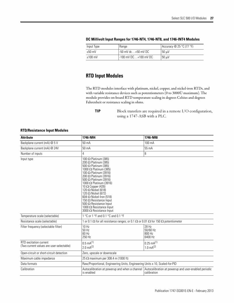
RTD Input Modules
The RTD modules interface with platinum, nickel, copper, and nickel-iron RTDs, and with variable resistance devices such as potentiometers (0 to 3000Ù maximum). The module provides on-board RTD temperature scaling in degrees Celsius and degrees Fahrenheit or resistance scaling in ohms.
DC Millivolt Input Ranges for 1746-NT4, 1746-NT8, and 1746-INT4 Modules
Input Type Range Accuracy @ 25 °C (77 °F)
±50 mV -50 mV dc…+50 mV DC 50 μV
±100 mV -100 mV DC…+100 mV DC 50 μV
TIP Block transfers are required in a remote I/O configuration, using a 1747-ASB with a PLC.
RTD/Resistance Input Modules
Attribute 1746-NR4 1746-NR8
Backplane current (mA) @ 5 V 50 mA 100 mA
Backplane current (mA) @ 24V 50 mA 55 mA
Number of inputs 4 8
Input type 100 Ω Platinum (385)200 Ω Platinum (385)500 Ω Platinum (385)1000 Ω Platinum (385)100 Ω Platinum (3916)200 Ω Platinum (3916)500 Ω Platinum (3916)1000 Ω Platinum (3916)10 Ω Copper (426)120 Ω Nickel (618)120 Ω Nickel (672)604 Ω Nickel-Iron (518)150 Ω Resistance Input500 Ω Resistance Input1000 Ω Resistance Input3000 Ω Resistance Input
Temperature scale (selectable) 1 °C or 1 °F and 0.1 °C and 0.1 °F
Resistance scale (selectable) 1 or 0.1 Ω for all resistance ranges; or 0.1 Ω or 0.01 Ω for 150 Ω potentiometer
Filter frequency (selectable filter) 10 Hz50 Hz60 Hz250 Hz
28 Hz50/60 Hz800 Hz6400 Hz
RTD excitation current(Two current values are user-selectable)
0.5 mA(1)
2.0 mA(2)0.25 mA(1)
1.0 mA(2)
Open-circuit or short-circuit detection Zero, upscale or downscale
Maximum cable impedance 25 Ω maximum per 308.4 m (1000 ft)
Data formats Raw/Proportional, Engineering Units, Engineering Units x 10, Scaled-for-PID
Calibration Autocalibration at powerup and when a channel is enabled
Autocalibration at powerup and user-enabled periodic calibration

Publication 1747-SG001E-EN-E - February 2013
28 Select SLC 500 I/O Modules
Isolation voltage, channel-to-channel None ±5V
Isolation voltage, input to backplane 500V AC for 1 minute
Common mode voltage separation ±1V maximum
(1) Cannot use for 10 Ω Copper RTD. Recommended for use with higher resistance ranges for both RTDs and direct response inputs (1000 Ω RTDs and 3000 Ω resistance input). Contact the RTD manufacturer for recommendations.
(2) Must use for 10 Ω Copper RTD. Recommended for use with all other RTD and direct resistance inputs, except 1000 Ω RTDs and 3000 Ω resistance ranges. Contact RTD manufacturer for recommendations.
RTD/Resistance Input Modules
Attribute 1746-NR4 1746-NR8
RTD Channel Step Response for 1746-NR4 and 1746-NR8
1746-NR4 1746-NR8
FilterFrequency
50 HzNMR
60 HzNMR
Cut-offFrequency
StepResponse
FilterFrequency
50 HzNMR
60 HzNMR
Cut-offFrequency
StepResponse
10 Hz 100 dB 2.62 Hz 300 ms 28 Hz 110 dB 95 dB 7.8 Hz 120 ms
50 Hz 100 dB – 13.1 Hz 60 ms 50/60 Hz 65 dB 13.65 Hz 68.6 ms
60 Hz – 100 dB 15.72 Hz 50 ms 800 Hz – – 209.8 Hz 3.75 ms
250 Hz – – 65.5 Hz 12 ms 6400 Hz – – 1677 Hz 1.47 ms
Update Time for 1746-NR4 and 1746-NR8
1746-NR4 1746-NR8
Filter Frequency Channel Scan Time(1) Filter Frequency Channel Scan Time With Lead Resistance Measurement
10 Hz 305 ms 28 Hz 125 ms 250 ms
50 Hz 65 ms 50/60 Hz 75 ms 147 ms
60 Hz 55 ms 800 Hz 10 ms 18 ms
250 Hz 17 ms 6400 Hz 6 ms 10 ms
(1) The module-scan time is obtained by summing the channel-scan time for each enabled channel. For example, if 3 channels are enabled and the 50 Hz filter is selected, the module-scan time is 3 x 65 ms = 195 ms.
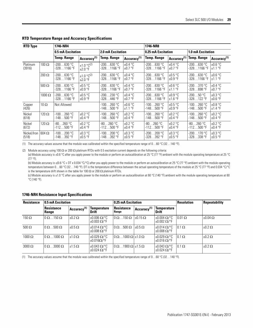
RTD Temperature Range and Accuracy Specifications
RTD Type 1746-NR4 1746-NR8
0.5 mA Excitation 2.0 mA Excitation 0.25 mA Excitation 1.0 mA Excitation
Temp. Range Accuracy(1) Temp. Range Accuracy(1) Temp. Range Accuracy(1) Temp. Range Accuracy(1)
Platinum(385)
100 Ω -200…850 °C-328…1562 °F
±1.0 °C(2) ±2.0 °F
-200…850 °C-328…1562 °F
±0.5 °C±0.9 °F
-200…850 °C-328…1562 °F
±0.5 °C±0.9 °F
-200…850 °C-328…1562 °F
±0.7 °C±1.3 °F
200 Ω -200…850 °C-328…1562 °F
±1.0 °C(2)
±2.0 °F-200…850 °C-328…1562 °F
±0.5 °C±0.9 °F
-200…850 °C-328…1562 °F
±0.6 °C±1.1 °F
-200…850 °C-328…1562 °F
±0.7 °C±1.3 °F
500 Ω -200…850 °C-328…1562 °F
±0.6 °C±1.1 °F
-200…850 °C-328…1562 °F
±0.5 °C±0.9 °F
-200…850 °C-328…1562 °F
±0.7 °C±1.3 °F
-200…370 °C-328…698 °F
±0.5 °C±0.9 °F
1000 Ω -200…850 °C-328…1562 °F
±0.6 °C±1.1 °F
-200…240 °C-328…464 °F
±0.5 °C±0.9 °F
-200…850 °C-328…1562 °F
±1.2 °C±2.2 °F
-200…50 °C-328…122 °F
±0.4 °C±0.7 °F
Publication 1747-SG001E-EN-E - February 2013
Select SLC 500 I/O Modules 29
Platinum(3916)
100 Ω -200…630 °C-328…1166 °F
±1.0 °C(2)
±2.0 °F-200…630 °C-328…1166 °F
±0.4 °C±0.7 °F
-200…630 °C-328…1166 °F
±0.4 °C±0.7 °F
-200…630 °C-328…1166 °F
±0.6 °C±1.1 °F
200 Ω -200…630 °C-328…1166 °F
±1.0 °C(2)
±2.0 °F-200…630 °C-328…1166 °F
±0.4 °C±0.7 °F
-200…630 °C-328…1166 °F
±0.5 °C±0.9 °F
-200…630 °C-328…1166 °F
±0.6 °C±1.1 °F
500 Ω -200…630 °C-328…1166 °F
±0.5 °C±0.9 °F
-200…630 °C-328…1166 °F
±0.4 °C±0.7 °F
-200…630 °C-328…1166 °F
±0.6 °C±1.1 °F
-200…370 °C-328…698 °F
±0.4 °C±0.7 °F
1000 Ω -200…630 °C-328…1166 °F
±0.5 °C±0.9 °F
-200…230 °C-328…446 °F
±0.4 °C±0.7 °F
-200…630 °C-328…1166 °F
±0.9 °C±1.6 °F
-200…50 °C-328…122 °F
±0.3 °C±0.6 °F
Copper(426)
10 Ω Not Allowed -100…260 °C-148…500 °F
±0.6 °C±1.1 °F
-100…260 °C-148…500 °F
±0.5 °C±0.9 °F
-100…260 °C-148…500 °F
±0.8 °C±1.4 °F
Nickel(618)
120 Ω -100…260 °C-148…500 °F
±0.2 °C±0.4 °F
-100…260 °C-148…500 °F
±0.2 °C±0.4 °F
-100…260 °C-148…500 °F
±0.2 °C±0.4 °F
-100…260 °C-148…500 °F
±0.2 °C±0.4 °F
Nickel(672)
120 Ω -80…260 °C-112…500 °F
±0.2 °C±0.4 °F
-80…260 °C-112…500 °F
±0.2 °C±0.4 °F
-80…260 °C-112…500 °F
±0.2 °C±0.4 °F
-80…260 °C-112…500 °F
±0.2 °C±0.4 °F
Nickel/Iron(518)
604 Ω -100…200 °C-148…392 °F
±0.3 °C±0.5 °F
-100…200 °C-148…392 °F
±0.3 °C±0.5 °F
-200…200 °C-328…392 °F
±0.3 °C±0.5 °F
-200…170 °C-328…338 °F
±0.3 °C±0.5 °F
(1) The accuracy values assume that the module was calibrated within the specified temperature range of 0…60 °C (32…140 °F).
(2) Module accuracy using 100 Ω or 200 Ω platinum RTDs with 0.5 excitation current depends on the following criteria:(a) Module accuracy is ±0.6 °C after you apply power to the module or perform an autocalibration at 25 °C (77 °F) ambient with the module operating temperature at 25 °C (77 °F).(b) Module accuracy is ±(0.6 °C + DT x 0.034 °C/°C) after you apply power to the module or perform an autocalibration at 25 °C (77 °F) ambient with the module operating temperature between 0…60 °C (32…140 °F). DT is the temperature difference between the actual operating temperature of the module at 25 °C (77 °F) and 0.034 °C/°C is the temperature drift shown in the table for 100 Ω or 200 Ω platinum RTDs.(c) Module accuracy is ±1.0 °C after you apply power to the module or perform an autocalibration at 60 °C (140 °F) ambient with the module operating temperature at 60 °C (140 °F).
RTD Temperature Range and Accuracy Specifications
RTD Type 1746-NR4 1746-NR8
0.5 mA Excitation 2.0 mA Excitation 0.25 mA Excitation 1.0 mA Excitation
Temp. Range Accuracy(1) Temp. Range Accuracy(1) Temp. Range Accuracy(1) Temp. Range Accuracy(1)
1746-NR4 Resistance Input Specifications
Resistance 0.5 mA Excitation 0.25 mA Excitation Resolution Repeatability
Resistance Range
Accuracy(1) TemperatureDrift
ResistanceRange
Accuracy(1) TemperatureDrift
150 Ω 0 Ω…150 Ω ±0.2 Ω ±0.006 Ω/°C±0.003 Ω/°F
0 Ω…150 Ω ±0.15 Ω ±0.004 Ω/°C±0.002 Ω/°F
0.01 Ω ±0.04 Ω
500 Ω 0 Ω…500 Ω ±0.5 Ω ±0.014 Ω/°C±0.008 Ω/°F
0 Ω…500 Ω ±0.5 Ω ±0.014 Ω/°C±0.008 Ω/°F
0.1 Ω ±0.2 Ω
1000 Ω 0 Ω…1000 Ω ±1.0 Ω ±0.029 Ω/°C±0.016Ω/°F
0 Ω…1000 Ω ±1.0 Ω ±0.029 Ω/°C±0.016 Ω/°F
0.1 Ω ±0.2 Ω
3000 Ω 0 Ω…3000 Ω ±1.5 Ω ±0.043 Ω/°C±0.024 Ω/°F
0 Ω…1900 Ω ±1.5 Ω ±0.043 Ω/°C±0.024 Ω/°F
0.1 Ω ±0.2 Ω
(1) The accuracy values assume that the module was calibrated within the specified temperature range of 0…60 °C (32…140 °F).
Publication 1747-SG001E-EN-E - February 2013
30 Select SLC 500 I/O Modules
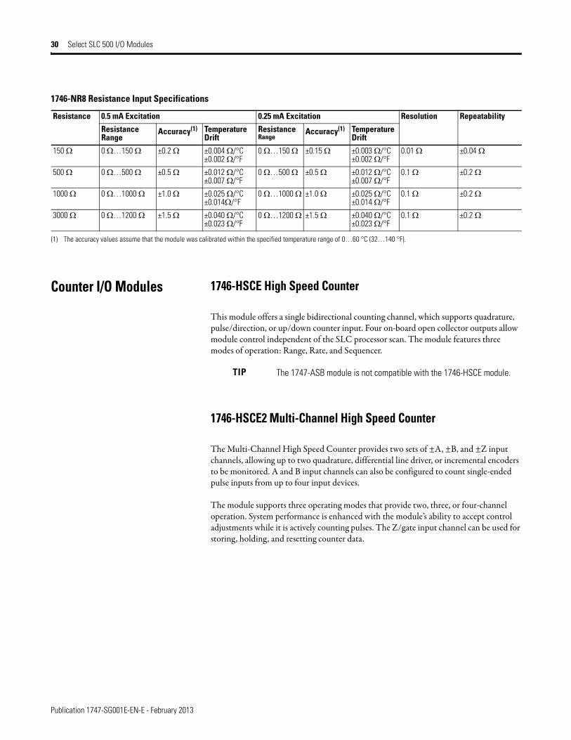
Counter I/O Modules 1746-HSCE High Speed Counter
This module offers a single bidirectional counting channel, which supports quadrature, pulse/direction, or up/down counter input. Four on-board open collector outputs allow module control independent of the SLC processor scan. The module features three modes of operation: Range, Rate, and Sequencer.
1746-HSCE2 Multi-Channel High Speed Counter
The Multi-Channel High Speed Counter provides two sets of ±A, ±B, and ±Z input channels, allowing up to two quadrature, differential line driver, or incremental encoders to be monitored. A and B input channels can also be configured to count single-ended pulse inputs from up to four input devices.
The module supports three operating modes that provide two, three, or four-channel operation. System performance is enhanced with the module’s ability to accept control adjustments while it is actively counting pulses. The Z/gate input channel can be used for storing, holding, and resetting counter data.
1746-NR8 Resistance Input Specifications
Resistance 0.5 mA Excitation 0.25 mA Excitation Resolution Repeatability
Resistance Range
Accuracy(1) TemperatureDrift
ResistanceRange
Accuracy(1) TemperatureDrift
150 Ω 0 Ω…150 Ω ±0.2 Ω ±0.004 Ω/°C±0.002 Ω/°F
0 Ω…150 Ω ±0.15 Ω ±0.003 Ω/°C±0.002 Ω/°F
0.01 Ω ±0.04 Ω
500 Ω 0 Ω…500 Ω ±0.5 Ω ±0.012 Ω/°C±0.007 Ω/°F
0 Ω…500 Ω ±0.5 Ω ±0.012 Ω/°C±0.007 Ω/°F
0.1 Ω ±0.2 Ω
1000 Ω 0 Ω…1000 Ω ±1.0 Ω ±0.025 Ω/°C±0.014Ω/°F
0 Ω…1000 Ω ±1.0 Ω ±0.025 Ω/°C±0.014 Ω/°F
0.1 Ω ±0.2 Ω
3000 Ω 0 Ω…1200 Ω ±1.5 Ω ±0.040 Ω/°C±0.023 Ω/°F
0 Ω…1200 Ω ±1.5 Ω ±0.040 Ω/°C±0.023 Ω/°F
0.1 Ω ±0.2 Ω
(1) The accuracy values assume that the module was calibrated within the specified temperature range of 0…60 °C (32…140 °F).
TIP The 1747-ASB module is not compatible with the 1746-HSCE module.

Publication 1747-SG001E-EN-E - February 2013
Select SLC 500 I/O Modules 31
Process Control Modules Blow Molding Module
This module features four independent axes of PID control plus one discrete I/O pair per channel for channel synchronization. The 1746-BLM module provides 256 points of resolution for each parison channel with interpolation, and has loop update times of 100 microseconds. Configurations include accumulator push-out control and three parison axis, and two accumulator push-outs and two parison axis.
The module is designed to work in a variety of applications, including accumulator machines, continuous extrusion machines, and reciprocating screw machines. The module performs its servo control task independently from the processor, but receives its configuration and run-time information from the processor.
High Speed Counter Specifications
Attribute 1746-HSCE 1746-HSCE2
Number of inputs 1 set ±A, ±B, ±Z differential or single-ended inputs, 5V DC, 12V DC, or 24V DC
2 sets ±A, ±B, ±Z, 2 quadrature encoders, or 4 pulse differential or single-ended inputs
Input voltage range Differential: 0…5V DCSingle-ended: ±5V DC5V DC: 3.8…5.5V DC12V DC: 9.4…16.5V DC24V DC: 16.5…30V DC
5V DC: 4.2…12V DC24V DC: 10…30V DC
Frequency 50 kHz for range32 kHz for rate50 kHz for sequencer
250 kHz @ X4500 kHz @ X21 MHz for all other
Maximum Counts 16-bit, ±32,768 24-bit, ±8,388,607 in Class 416-bit, ±32,768 in Class 1
Throughput Sequencer mode: 1.8 msRange mode: 3.9 ms
700 μs (typical)
Number of outputs 4 open-collector outputs: 5, 12, or 24V DC
4 outputs: 5…30V DC sourcing with electronic protection
Maximum output current 16 mA @ 4.5V DC40 mA @ 10V DC125 mA @ 30V DC
1 A
Backplane current (mA) @ 5V 320 mA 250 mA
Backplane current (mA) @ 24V 0 mA 0 mA
Isolation voltage Tested @ 1500V Tested @ 1000V
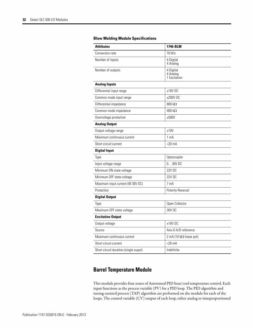
Blow Molding Module Specifications
Atttibutes 1746-BLM
Common Specifications
Backplane current (mA) @ 5V 110 mA
Resolution 14 bits
Isolation voltage Tested @ 500V DC for 60 s
Publication 1747-SG001E-EN-E - February 2013
32 Select SLC 500 I/O Modules
Barrel Temperature Module
This module provides four zones of Autotuned PID heat/cool temperature control. Each input functions as the process variable (PV) for a PID loop. The PID algorithm and tuning-assisted process (TAP) algorithm are performed on the module for each of the loops. The control variable (CV) output of each loop, either analog or timeproportioned
Conversion rate 10 kHz
Number of inputs 4 Digital4 Analog
Number of outputs 4 Digital4 Analog1 Excitation
Analog Inputs
Differential input range ±10V DC
Common mode input range ±200V DC
Differential impedance 800 kΩ
Common mode impedance 400 kΩ
Overvoltage protection ±500V
Analog Output
Output voltage range ±10V
Maximum continuous current 1 mA
Short circuit current <20 mA
Digital Input
Type Optocoupler
Input voltage range 0…30V DC
Minimum ON state voltage 22V DC
Minimum OFF state voltage 22V DC
Maximum input current (@ 30V DC) 7 mA
Protection Polarity Reversal
Digital Output
Type Open Collector
Maximum OFF state voltage 30V DC
Excitation Output
Output voltage ±10V DC
Source Axis 0 A/D reference
Maximum continuous current 2 mA (10 kΩ linear pot)
Short circuit current <20 mA
Short circuit duration (single ouput) Indefinite
Blow Molding Module Specifications
Atttibutes 1746-BLM
Publication 1747-SG001E-EN-E - February 2013
Select SLC 500 I/O Modules 33
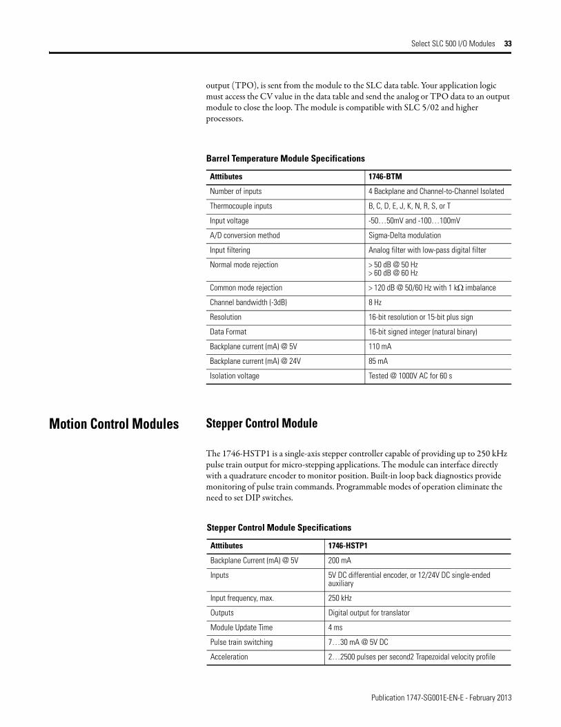
output (TPO), is sent from the module to the SLC data table. Your application logic must access the CV value in the data table and send the analog or TPO data to an output module to close the loop. The module is compatible with SLC 5/02 and higher processors.
Motion Control Modules Stepper Control Module
The 1746-HSTP1 is a single-axis stepper controller capable of providing up to 250 kHz pulse train output for micro-stepping applications. The module can interface directly with a quadrature encoder to monitor position. Built-in loop back diagnostics provide monitoring of pulse train commands. Programmable modes of operation eliminate the need to set DIP switches.
Barrel Temperature Module Specifications
Atttibutes 1746-BTM
Number of inputs 4 Backplane and Channel-to-Channel Isolated
Thermocouple inputs B, C, D, E, J, K, N, R, S, or T
Input voltage -50…50mV and -100…100mV
A/D conversion method Sigma-Delta modulation
Input filtering Analog filter with low-pass digital filter
Normal mode rejection > 50 dB @ 50 Hz> 60 dB @ 60 Hz
Common mode rejection > 120 dB @ 50/60 Hz with 1 kΩ imbalance
Channel bandwidth (-3dB) 8 Hz
Resolution 16-bit resolution or 15-bit plus sign
Data Format 16-bit signed integer (natural binary)
Backplane current (mA) @ 5V 110 mA
Backplane current (mA) @ 24V 85 mA
Isolation voltage Tested @ 1000V AC for 60 s
Stepper Control Module Specifications
Atttibutes 1746-HSTP1
Backplane Current (mA) @ 5V 200 mA
Inputs 5V DC differential encoder, or 12/24V DC single-ended auxiliary
Input frequency, max. 250 kHz
Outputs Digital output for translator
Module Update Time 4 ms
Pulse train switching 7…30 mA @ 5V DC
Acceleration 2…2500 pulses per second2 Trapezoidal velocity profile
Publication 1747-SG001E-EN-E - February 2013
34 Select SLC 500 I/O Modules
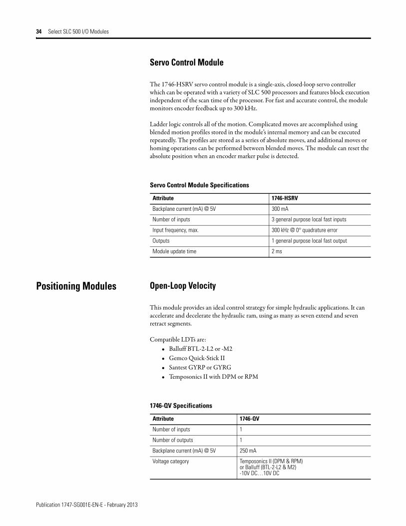
Servo Control Module
The 1746-HSRV servo control module is a single-axis, closed-loop servo controller which can be operated with a variety of SLC 500 processors and features block execution independent of the scan time of the processor. For fast and accurate control, the module monitors encoder feedback up to 300 kHz.
Ladder logic controls all of the motion. Complicated moves are accomplished using blended motion profiles stored in the module’s internal memory and can be executed repeatedly. The profiles are stored as a series of absolute moves, and additional moves or homing operations can be performed between blended moves. The module can reset the absolute position when an encoder marker pulse is detected.
Positioning Modules Open-Loop Velocity
This module provides an ideal control strategy for simple hydraulic applications. It can accelerate and decelerate the hydraulic ram, using as many as seven extend and seven retract segments.
Compatible LDTs are:• Balluff BTL-2-L2 or -M2• Gemco Quick-Stick II• Santest GYRP or GYRG• Temposonics II with DPM or RPM
Servo Control Module Specifications
Attribute 1746-HSRV
Backplane current (mA) @ 5V 300 mA
Number of inputs 3 general purpose local fast inputs
Input frequency, max. 300 kHz @ 0° quadrature error
Outputs 1 general purpose local fast output
Module update time 2 ms
1746-QV Specifications
Attribute 1746-QV
Number of inputs 1
Number of outputs 1
Backplane current (mA) @ 5V 250 mA
Voltage category Temposonics II (DPM & RPM)or Balluff (BTL-2-L2 & M2)-10V DC…10V DC

Publication 1747-SG001E-EN-E - February 2013
Select SLC 500 I/O Modules 35
Synchronized Axes Module
This module offers four axes of closed-loop servo positioning control, using internal logic to synchronize multiple axes. The 1746-QS features a differential interface to either pulse-width modulated (DPM) or start/stop pulse (RPM) linear displacement transducer (LDT) inputs.
Compatible LDTs are:• Balluff BTL-2-L2 or -M2• Gemco Quick-Stick II• Santest GYRP or GYRG• Temposonics II with DPM or RPM
Use the 1492-AIFMQS interface module and the 1492-ACABLExxQ (xx = cable length) pre-wired cable with the 1746-QS module. The 1492-AIFMQS interface module is required for CE certification.
Independent powersource requirement
0.400 mA @ +15V DCand 0.295 A @ -15V DC(typical but not LDT-dependent)
LDT Inputs InterrogateGate15V Dc PSPS CommonShield/Frame
Module resolution and range 160 in ±0.01 in.
Analog output 0…10V DC @ 250 mA or-10…+10V DC @ 250 mA
Accuracy of voltage output within ±1% of its programmed value
Module update time 2 ms
1746-QS Specifications
Attribute 1746-QV
Number of inputs 4
Number of outputs 4
Backplane current (mA) @ 5V 1000 mA
Backplane current (mA) @ 5V 200 mA
Voltage category Input: LDT with RPM or DPMOutput: -10V DC…10V DC
Analog output -10…10V DC @ 5 mA
Output resolution 12-bit
Module update time 2 ms
1746-QV Specifications
Attribute 1746-QV
Publication 1747-SG001E-EN-E - February 2013
36 Select SLC 500 I/O Modules
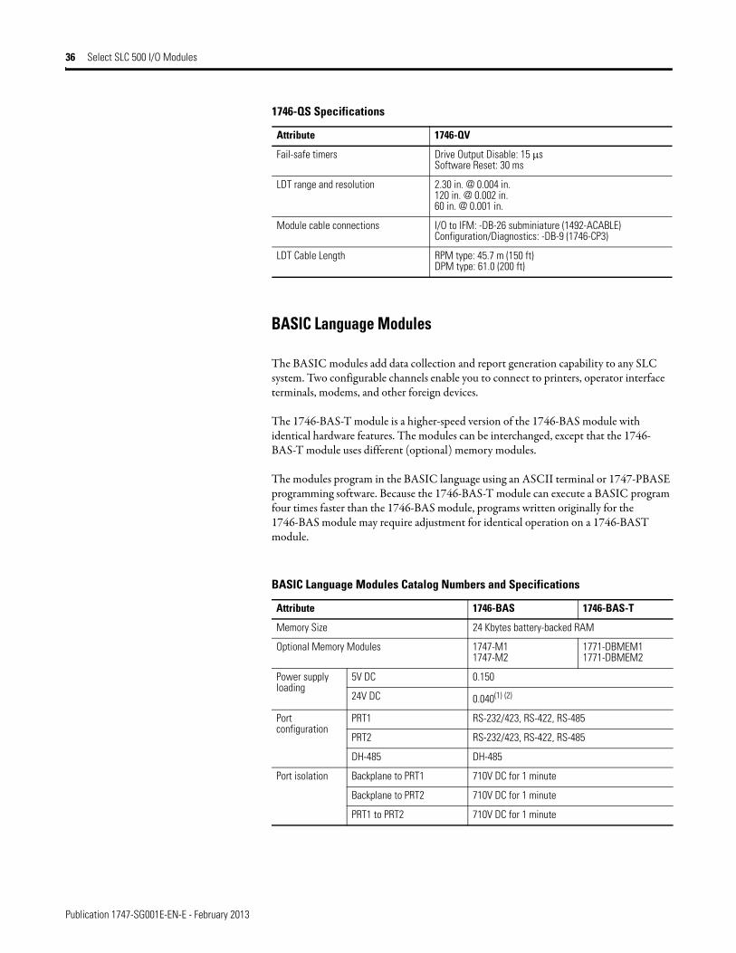
BASIC Language Modules
The BASIC modules add data collection and report generation capability to any SLC system. Two configurable channels enable you to connect to printers, operator interface terminals, modems, and other foreign devices.
The 1746-BAS-T module is a higher-speed version of the 1746-BAS module with identical hardware features. The modules can be interchanged, except that the 1746- BAS-T module uses different (optional) memory modules.
The modules program in the BASIC language using an ASCII terminal or 1747-PBASE programming software. Because the 1746-BAS-T module can execute a BASIC program four times faster than the 1746-BAS module, programs written originally for the 1746-BAS module may require adjustment for identical operation on a 1746-BAST module.
Fail-safe timers Drive Output Disable: 15 μsSoftware Reset: 30 ms
LDT range and resolution 2.30 in. @ 0.004 in.120 in. @ 0.002 in.60 in. @ 0.001 in.
Module cable connections I/O to IFM: -DB-26 subminiature (1492-ACABLE)Configuration/Diagnostics: -DB-9 (1746-CP3)
LDT Cable Length RPM type: 45.7 m (150 ft)DPM type: 61.0 (200 ft)
BASIC Language Modules Catalog Numbers and Specifications
Attribute 1746-BAS 1746-BAS-T
Memory Size 24 Kbytes battery-backed RAM
Optional Memory Modules 1747-M11747-M2
1771-DBMEM11771-DBMEM2
Power supply loading
5V DC 0.150
24V DC 0.040(1) (2)
Port configuration
PRT1 RS-232/423, RS-422, RS-485
PRT2 RS-232/423, RS-422, RS-485
DH-485 DH-485
Port isolation Backplane to PRT1 710V DC for 1 minute
Backplane to PRT2 710V DC for 1 minute
PRT1 to PRT2 710V DC for 1 minute
1746-QS Specifications
Attribute 1746-QV

Publication 1747-SG001E-EN-E - February 2013
Select SLC 500 I/O Modules 37
Windows-compatible BASIC Module Interface Software (1747-WINBAS)
BASIC Software is a terminal emulation program specifically written for you to interface to a Rockwell Automation 1746-BAS, 1746-BAS-T, or 1771-DB BASIC module. BASIC software simplifies the uploading and downloading of BASIC module programs, as well as backing up and restoring complete module images. BASIC software also provides debugging tools to aid in troubleshooting BASIC programs while online.
As a terminal emulation program, BASIC software requires either one RS-232 serial COM port or a DH-485 interface (1784-PCMK, 1784-PKTX, 1784-PKTXD, or 1747-UIC converter) be available on the personal computers. Bridging to the DH-485 network from other networks is not supported.
BASIC software works on personal computers with Windows 98, 2000, NT, and XP operating systems. RSLinx Classic OEM software must be installed on the personal computer to communicate to the 1746-BAS module via the DH-485 interface.
Maximum communication distance
RS-232 (300…19200 bps) 15 m (50 ft)
RS-423 (300 bps) 1230 m (4000 ft)
RS-423 (600 bps) 920 m (3000 ft)
RS-423 (1200 bps) 770 m (2500 ft)
RS-423 (4800 bps) 245 m (800 ft)
RS-423 (9600 bps) 120 m (400 ft)
RS-423 (19200 bps) 60 m (200 ft)
RS-422 (300…19200 bps) 1230 m (4000 ft)
RS-485 (300…19200 bps) 1230 m (4000 ft)
Data Transfer SLC 5/01 8 input words (SLC input image table)8 output words (SLC output image table)
SLC 5/02 and higher 8 input words (SLC input image table)8 output words (SLC output image table)64 input and 64 output words (SLC M0/M1 file)
Data Rates 300…19,200 baud
Modem support DF1 half-duplex slave or full duplex
Clock/calendar accuracy ±1 minute/month @ 25 °C (77 °F)0, -6 minutes/month @ 60 °C (140 °F)
(1) If the BASIC Module DH-485 channel is connected to a 1747-AIC Link Coupler, add 0.085 A to the BASIC module’s power supply loading value @ 24V DC.
(2) If the BASIC Module is connected to any device (for example, DTAM) either directly or through a 1747-AIC Link Coupler, add the appropriate current loading for the device to the BASIC module’s power supply loading value @ 24V DC.
BASIC Language Modules Catalog Numbers and Specifications
Attribute 1746-BAS 1746-BAS-T
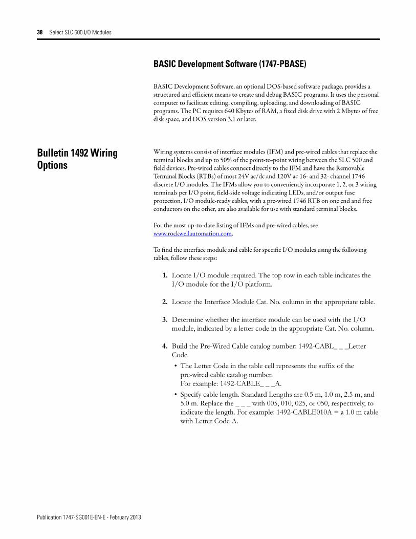
Publication 1747-SG001E-EN-E - February 2013
38 Select SLC 500 I/O Modules
BASIC Development Software (1747-PBASE)
BASIC Development Software, an optional DOS-based software package, provides a structured and efficient means to create and debug BASIC programs. It uses the personal computer to facilitate editing, compiling, uploading, and downloading of BASIC programs. The PC requires 640 Kbytes of RAM, a fixed disk drive with 2 Mbytes of free disk space, and DOS version 3.1 or later.
Bulletin 1492 Wiring Options
Wiring systems consist of interface modules (IFM) and pre-wired cables that replace the terminal blocks and up to 50% of the point-to-point wiring between the SLC 500 and field devices. Pre-wired cables connect directly to the IFM and have the Removable Terminal Blocks (RTBs) of most 24V ac/dc and 120V ac 16- and 32- channel 1746 discrete I/O modules. The IFMs allow you to conveniently incorporate 1, 2, or 3 wiring terminals per I/O point, field-side voltage indicating LEDs, and/or output fuse protection. I/O module-ready cables, with a pre-wired 1746 RTB on one end and free conductors on the other, are also available for use with standard terminal blocks.
For the most up-to-date listing of IFMs and pre-wired cables, see www.rockwellautomation.com.
To find the interface module and cable for specific I/O modules using the following tables, follow these steps:
1. Locate I/O module required. The top row in each table indicates the I/O module for the I/O platform.
2. Locate the Interface Module Cat. No. column in the appropriate table.
3. Determine whether the interface module can be used with the I/O module, indicated by a letter code in the appropriate Cat. No. column.
4. Build the Pre-Wired Cable catalog number: 1492-CABL_ _ _Letter Code.
• The Letter Code in the table cell represents the suffix of the pre-wired cable catalog number.For example: 1492-CABLE_ _ _A.
• Specify cable length. Standard Lengths are 0.5 m, 1.0 m, 2.5 m, and 5.0 m. Replace the _ _ _ with 005, 010, 025, or 050, respectively, to indicate the length. For example: 1492-CABLE010A = a 1.0 m cable with Letter Code A.

Publication 1747-SG001E-EN-E - February 2013
Select SLC 500 I/O Modules 39
Feed-through 20-Terminal IFMs
Description Cat. No.
I/O Module Catalog Number 1746-
IA16
IB16
IC16
IG16
IH16
IM16
IN16
ITB16
ITV16
IV16
OA16
OB16
OB16E
OBP16
OG16
OV16
OVP16
OW16
OX8
Standard 264V AC/DC max
1492-IFM20F
A B E B B A B B B B C E E E E E E D D
Narrow standard 132V AC/DC max.
1492-IFM20FN
A B E B B – B B B B C E E E E E E N N
Extra terminals (2 per I/O) 264V AC/DC max.
1492-IFM20F-2
A B E B B A B B B B C E E E E E E D –
3-wire sensor type input devices 132V AC/DC max
1492-IFM20F-3
A B E B B – B B B B – – – – – – – – –
LED Indicating 20-Terminal IFMs
Description Cat. No. I/O Module Catalog Number 1746-
IA16
IB16
IC16
IG16
IH16
IM16
IN16
ITB16
ITV16
IV16
OA16
OB16
OB16E
OBP16
OG16
OV16
OVP16
OW16
OX8
Standard with 24V AC/DC LEDs
1492-IFM20D24
– B – – – – B B B B – E E E – E E D –
Narrow standard with 24V AC/DC LEDs
1492-IFM20D24N
– B – – – – B B B B – E E E – – – N –
Standard with 120V AC/DC LEDs
1492-IFM20D120
A – – – B – – – – – (1) – – – – – – D –
Narrow standard with 120V AC LEDs
1492-IFM20D120N
A – – – – – – – – – G – – – – – – N –
24V AC/DC LEDs and extra terminals for outputs
1492-IFM20D24-2
– – – – – – – – – – – E E E – E E D –
24V AC/DC LEDs and extra terminals for inputs
1492-IFM20D24A-2
– B – – – – B B B B – – – – – – – – –
120V AC LEDs and extra terminals for outputs
1492-IFM20D120-2
– – – – – – – – – – C – – – – – – D –
120V AC LEDs and extra terminals for inputs
1492-IFM20D120A-2
A – – – – – – – – – – – – – – – – – –
3-wire sensor with 24V AC/DC LEDs
1492-IFM20D24-3
– B – – – – B B B B – – – – – – – – –
8 Individually isolated with 24/48V AC/DC LEDs and 4 terminals/output
1492-IFM20DS24-4
– – – – – – – – – – – – – – – – – – S
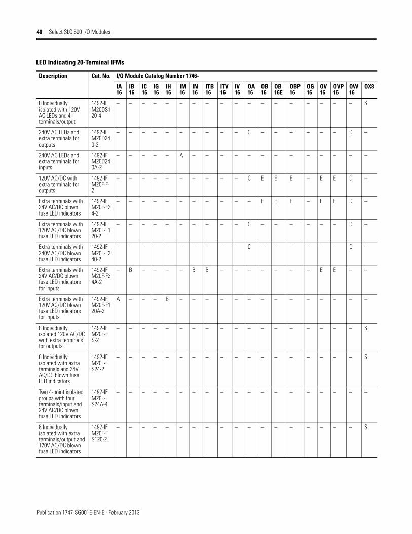
Publication 1747-SG001E-EN-E - February 2013
40 Select SLC 500 I/O Modules
8 Individually isolated with 120V AC LEDs and 4 terminals/output
1492-IFM20DS120-4
– – – – – – – – – – – – – – – – – – S
240V AC LEDs and extra terminals for outputs
1492-IFM20D240-2
– – – – – – – – – – C – – – – – – D –
240V AC LEDs and extra terminals for inputs
1492-IFM20D240A-2
– – – – – A – – – – – – – – – – – – –
120V AC/DC with extra terminals for outputs
1492-IFM20F-F-2
– – – – – – – – – – C E E E – E E D –
Extra terminals with 24V AC/DC blown fuse LED indicators
1492-IFM20F-F24-2
– – – – – – – – – – – E E E – E E D –
Extra terminals with 120V AC/DC blown fuse LED indicators
1492-IFM20F-F120-2
– – – – – – – – – – C – – – – – – D –
Extra terminals with 240V AC/DC blown fuse LED indicators
1492-IFM20F-F240-2
– – – – – – – – – – C – – – – – – D –
Extra terminals with 24V AC/DC blown fuse LED indicators for inputs
1492-IFM20F-F24A-2
– B – – – – B B – – – – – – – E E – –
Extra terminals with 120V AC/DC blown fuse LED indicators for inputs
1492-IFM20F-F120A-2
A – – – B – – – – – – – – – – – – – –
8 Individually isolated 120V AC/DC with extra terminals for outputs
1492-IFM20F-FS-2
– – – – – – – – – – – – – – – – – – S
8 Individually isolated with extra terminals and 24V AC/DC blown fuse LED indicators
1492-IFM20F-FS24-2
– – – – – – – – – – – – – – – – – – S
Two 4-point isolated groups with four terminals/input and 24V AC/DC blown fuse LED indicators
1492-IFM20F-FS24A-4
– – – – – – – – – – – – – – – – – – –
8 Individually isolated with extra terminals/output and 120V AC/DC blown fuse LED indicators
1492-IFM20F-FS120-2
– – – – – – – – – – – – – – – – – – S
LED Indicating 20-Terminal IFMs
Description Cat. No. I/O Module Catalog Number 1746-
IA16
IB16
IC16
IG16
IH16
IM16
IN16
ITB16
ITV16
IV16
OA16
OB16
OB16E
OBP16
OG16
OV16
OVP16
OW16
OX8
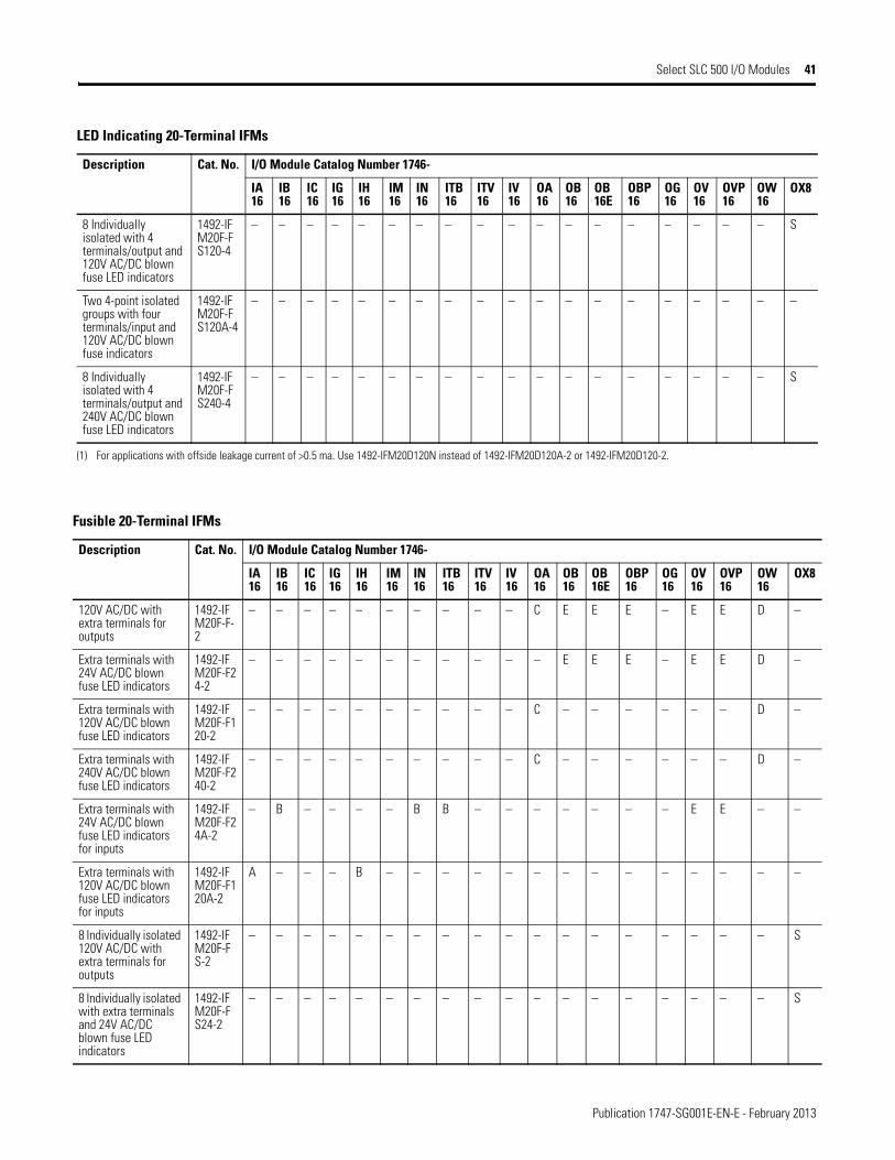
Publication 1747-SG001E-EN-E - February 2013
Select SLC 500 I/O Modules 41
8 Individually isolated with 4 terminals/output and 120V AC/DC blown fuse LED indicators
1492-IFM20F-FS120-4
– – – – – – – – – – – – – – – – – – S
Two 4-point isolated groups with four terminals/input and 120V AC/DC blown fuse indicators
1492-IFM20F-FS120A-4
– – – – – – – – – – – – – – – – – – –
8 Individually isolated with 4 terminals/output and 240V AC/DC blown fuse LED indicators
1492-IFM20F-FS240-4
– – – – – – – – – – – – – – – – – – S
(1) For applications with offside leakage current of >0.5 ma. Use 1492-IFM20D120N instead of 1492-IFM20D120A-2 or 1492-IFM20D120-2.
LED Indicating 20-Terminal IFMs
Description Cat. No. I/O Module Catalog Number 1746-
IA16
IB16
IC16
IG16
IH16
IM16
IN16
ITB16
ITV16
IV16
OA16
OB16
OB16E
OBP16
OG16
OV16
OVP16
OW16
OX8
Fusible 20-Terminal IFMs
Description Cat. No. I/O Module Catalog Number 1746-
IA16
IB16
IC16
IG16
IH16
IM16
IN16
ITB16
ITV16
IV16
OA16
OB16
OB16E
OBP16
OG16
OV16
OVP16
OW16
OX8
120V AC/DC with extra terminals for outputs
1492-IFM20F-F-2
– – – – – – – – – – C E E E – E E D –
Extra terminals with 24V AC/DC blown fuse LED indicators
1492-IFM20F-F24-2
– – – – – – – – – – – E E E – E E D –
Extra terminals with 120V AC/DC blown fuse LED indicators
1492-IFM20F-F120-2
– – – – – – – – – – C – – – – – – D –
Extra terminals with 240V AC/DC blown fuse LED indicators
1492-IFM20F-F240-2
– – – – – – – – – – C – – – – – – D –
Extra terminals with 24V AC/DC blown fuse LED indicators for inputs
1492-IFM20F-F24A-2
– B – – – – B B – – – – – – – E E – –
Extra terminals with 120V AC/DC blown fuse LED indicators for inputs
1492-IFM20F-F120A-2
A – – – B – – – – – – – – – – – – – –
8 Individually isolated 120V AC/DC with extra terminals for outputs
1492-IFM20F-FS-2
– – – – – – – – – – – – – – – – – – S
8 Individually isolated with extra terminals and 24V AC/DC blown fuse LED indicators
1492-IFM20F-FS24-2
– – – – – – – – – – – – – – – – – – S
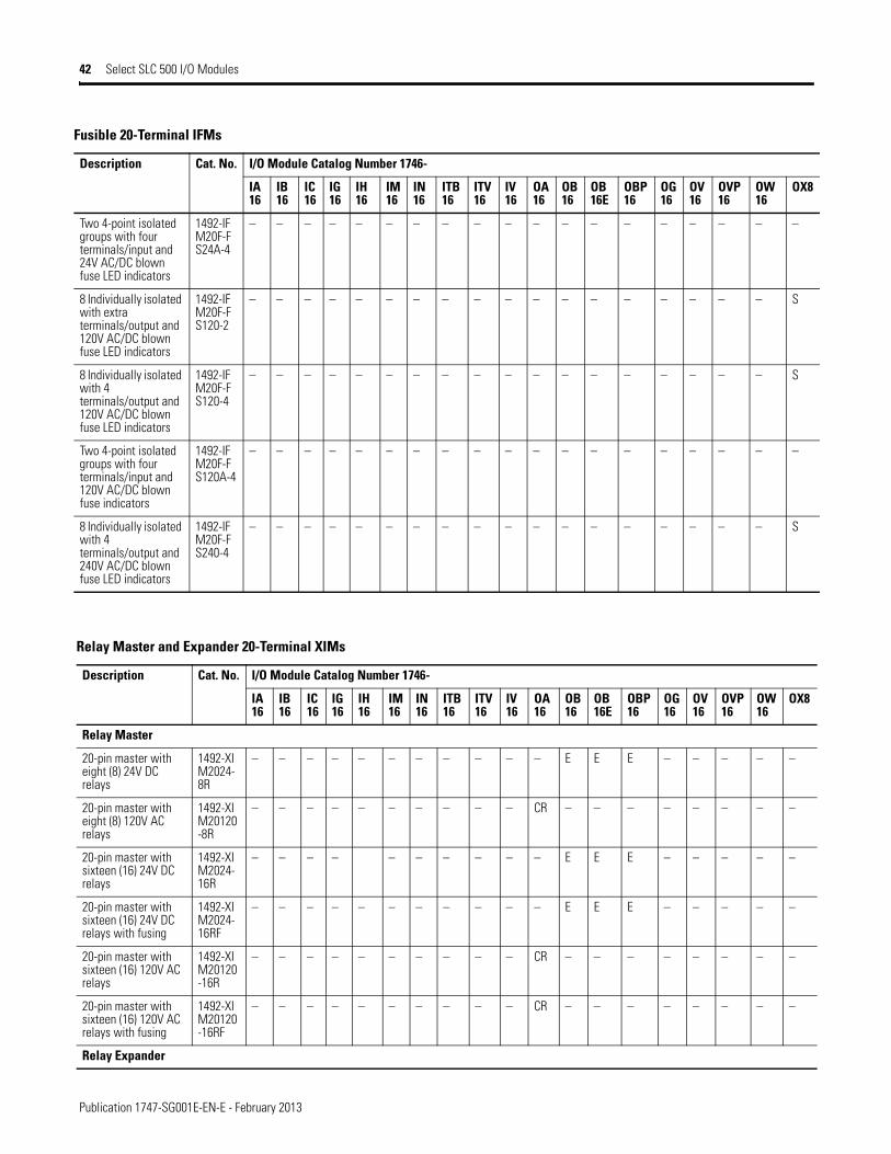
Publication 1747-SG001E-EN-E - February 2013
42 Select SLC 500 I/O Modules
Two 4-point isolated groups with four terminals/input and 24V AC/DC blown fuse LED indicators
1492-IFM20F-FS24A-4
– – – – – – – – – – – – – – – – – – –
8 Individually isolated with extra terminals/output and 120V AC/DC blown fuse LED indicators
1492-IFM20F-FS120-2
– – – – – – – – – – – – – – – – – – S
8 Individually isolated with 4 terminals/output and 120V AC/DC blown fuse LED indicators
1492-IFM20F-FS120-4
– – – – – – – – – – – – – – – – – – S
Two 4-point isolated groups with four terminals/input and 120V AC/DC blown fuse indicators
1492-IFM20F-FS120A-4
– – – – – – – – – – – – – – – – – – –
8 Individually isolated with 4 terminals/output and 240V AC/DC blown fuse LED indicators
1492-IFM20F-FS240-4
– – – – – – – – – – – – – – – – – – S
Fusible 20-Terminal IFMs
Description Cat. No. I/O Module Catalog Number 1746-
IA16
IB16
IC16
IG16
IH16
IM16
IN16
ITB16
ITV16
IV16
OA16
OB16
OB16E
OBP16
OG16
OV16
OVP16
OW16
OX8
Relay Master and Expander 20-Terminal XIMs
Description Cat. No. I/O Module Catalog Number 1746-
IA16
IB16
IC16
IG16
IH16
IM16
IN16
ITB16
ITV16
IV16
OA16
OB16
OB16E
OBP16
OG16
OV16
OVP16
OW16
OX8
Relay Master
20-pin master with eight (8) 24V DC relays
1492-XIM2024-8R
– – – – – – – – – – – E E E – – – – –
20-pin master with eight (8) 120V AC relays
1492-XIM20120-8R
– – – – – – – – – – CR – – – – – – – –
20-pin master with sixteen (16) 24V DC relays
1492-XIM2024-16R
– – – – – – – – – – E E E – – – – –
20-pin master with sixteen (16) 24V DC relays with fusing
1492-XIM2024-16RF
– – – – – – – – – – – E E E – – – – –
20-pin master with sixteen (16) 120V AC relays
1492-XIM20120-16R
– – – – – – – – – – CR – – – – – – – –
20-pin master with sixteen (16) 120V AC relays with fusing
1492-XIM20120-16RF
– – – – – – – – – – CR – – – – – – – –
Relay Expander
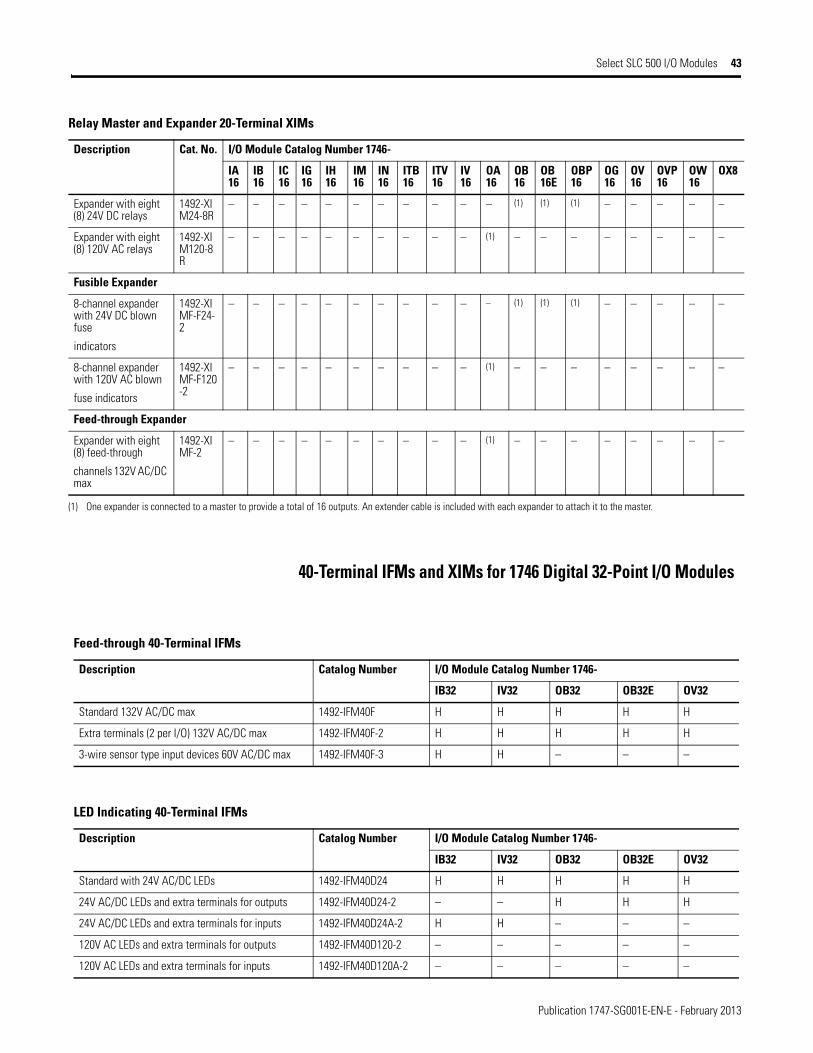
Publication 1747-SG001E-EN-E - February 2013
Select SLC 500 I/O Modules 43
40-Terminal IFMs and XIMs for 1746 Digital 32-Point I/O Modules
Expander with eight (8) 24V DC relays
1492-XIM24-8R
– – – – – – – – – – – (1) (1) (1) – – – – –
Expander with eight (8) 120V AC relays
1492-XIM120-8R
– – – – – – – – – – (1) – – – – – – – –
Fusible Expander
8-channel expander with 24V DC blown fuse
indicators
1492-XIMF-F24-2
– – – – – – – – – – – (1) (1) (1) – – – – –
8-channel expander with 120V AC blown
fuse indicators
1492-XIMF-F120-2
– – – – – – – – – – (1) – – – – – – – –
Feed-through Expander
Expander with eight (8) feed-through
channels 132V AC/DC max
1492-XIMF-2
– – – – – – – – – – (1) – – – – – – – –
(1) One expander is connected to a master to provide a total of 16 outputs. An extender cable is included with each expander to attach it to the master.
Relay Master and Expander 20-Terminal XIMs
Description Cat. No. I/O Module Catalog Number 1746-
IA16
IB16
IC16
IG16
IH16
IM16
IN16
ITB16
ITV16
IV16
OA16
OB16
OB16E
OBP16
OG16
OV16
OVP16
OW16
OX8
Feed-through 40-Terminal IFMs
Description Catalog Number I/O Module Catalog Number 1746-
IB32 IV32 OB32 OB32E OV32
Standard 132V AC/DC max 1492-IFM40F H H H H H
Extra terminals (2 per I/O) 132V AC/DC max 1492-IFM40F-2 H H H H H
3-wire sensor type input devices 60V AC/DC max 1492-IFM40F-3 H H – – –
LED Indicating 40-Terminal IFMs
Description Catalog Number I/O Module Catalog Number 1746-
IB32 IV32 OB32 OB32E OV32
Standard with 24V AC/DC LEDs 1492-IFM40D24 H H H H H
24V AC/DC LEDs and extra terminals for outputs 1492-IFM40D24-2 – – H H H
24V AC/DC LEDs and extra terminals for inputs 1492-IFM40D24A-2 H H – – –
120V AC LEDs and extra terminals for outputs 1492-IFM40D120-2 – – – – –
120V AC LEDs and extra terminals for inputs 1492-IFM40D120A-2 – – – – –

Publication 1747-SG001E-EN-E - February 2013
44 Select SLC 500 I/O Modules
3-wire sensor with 24V AC/DC LEDs 1492-IFM40D24-3 H H – – –
16 Individually isolated with 24/48V AC/DC LEDs and four terminals/output
1492-IFM40DS24-4 – – – – –
16 Individually isolated with 24V AC/DC LEDs and four terminals/input
1492-IFM40DS24A-4 – – – – –
16 Individually isolated with 120V AC LEDs and four terminals/output
1492-IFM40DS120-4 – – – – –
16 Individually isolated with 120V AC LEDs and four terminals/input
1492-IFM40DS120A-4 – – – – –
16 Individually isolated with 240V AC LEDs and four terminals/input
1492-IFM40DS240A-4 – – – – –
LED Indicating 40-Terminal IFMs
Description Catalog Number I/O Module Catalog Number 1746-
IB32 IV32 OB32 OB32E OV32
Fusible 40-Terminal IFMs
Description Catalog Number I/O Module Catalog Number 1746-
IB32 IV32 OB32 OB32E OV32
120V AC/DC with extra terminals for outputs 1492-IFM40F-F-2 – – H H H
Extra terminals with 24V AC/DC blown fuse indicators for outputs
1492-IFM40F-F24-2 – – H H H
Extra terminals with 120V AC/DC blown fuse indicators for outputs
1492-IFM40F-F120-2 – – – – –
16 Individually isolated with extra terminals for 120V AC/DC outputs
1492-IFM40F-FS-2 – – – – –
16 individually isolated with extra terminals and 24V AC/DC blown fuse indicators
1492-IFM40F-FS24-2 – – – – –
16 Individually isolated with 24V AC/DC blown fuse indicators and four terminals/output
1492-IFM40F-FS24-4 – – – – –
16 Individually isolated with extra terminals and 120V AC/DC blown fuse LED indicators
1492-IFM40F-FS120-2 – – – – –
16 Individually isolated with 120V AC/DC blown fuse indicators and four terminals/output
1492-IFM40F-FS120-4 – – – – –
16 Individually isolated with 240V AC/DC blown fuse indicators and four terminals/output
1492-IFM40F-FS240-4 – – – – –
16 Individually isolated with 24V AC/DC blown fuse indicators and four terminals/input
1492-IFM40F-FS24A-4 – – – – –
16 Individually isolated with 120V AC/DC blown fuse indicators and four terminals/input
1492-IFM40F-FS120A-4 – – – – –
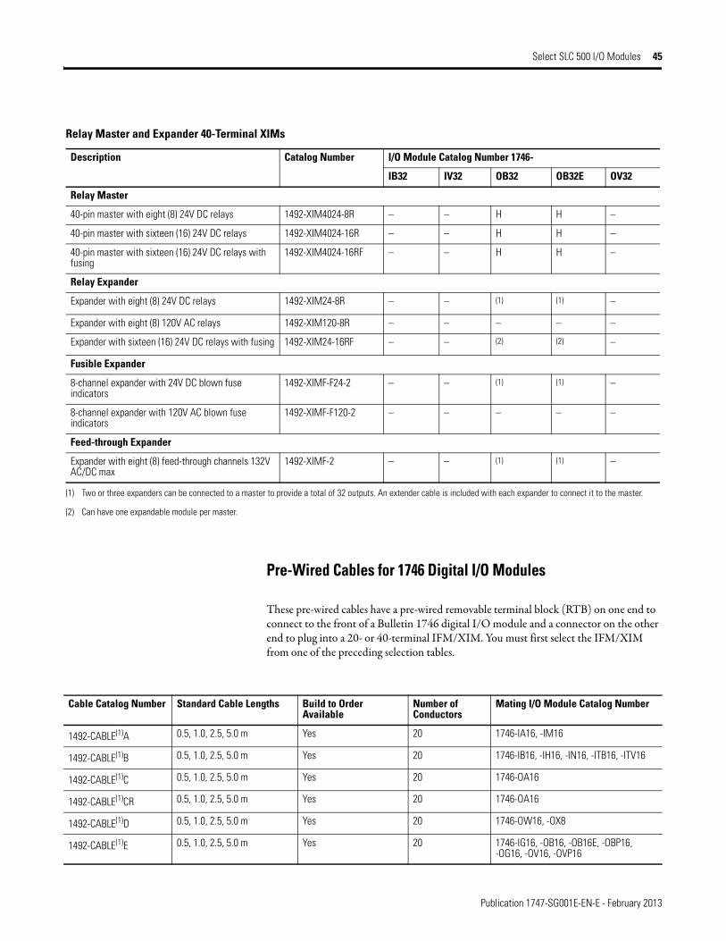
Publication 1747-SG001E-EN-E - February 2013
Select SLC 500 I/O Modules 45
Pre-Wired Cables for 1746 Digital I/O Modules
These pre-wired cables have a pre-wired removable terminal block (RTB) on one end to connect to the front of a Bulletin 1746 digital I/O module and a connector on the other end to plug into a 20- or 40-terminal IFM/XIM. You must first select the IFM/XIM from one of the preceding selection tables.
Relay Master and Expander 40-Terminal XIMs
Description Catalog Number I/O Module Catalog Number 1746-
IB32 IV32 OB32 OB32E OV32
Relay Master
40-pin master with eight (8) 24V DC relays 1492-XIM4024-8R – – H H –
40-pin master with sixteen (16) 24V DC relays 1492-XIM4024-16R – – H H –
40-pin master with sixteen (16) 24V DC relays with fusing
1492-XIM4024-16RF – – H H –
Relay Expander
Expander with eight (8) 24V DC relays 1492-XIM24-8R – – (1) (1) –
Expander with eight (8) 120V AC relays 1492-XIM120-8R – – – – –
Expander with sixteen (16) 24V DC relays with fusing 1492-XIM24-16RF – – (2) (2) –
Fusible Expander
8-channel expander with 24V DC blown fuse indicators
1492-XIMF-F24-2 – – (1) (1) –
8-channel expander with 120V AC blown fuse indicators
1492-XIMF-F120-2 – – – – –
Feed-through Expander
Expander with eight (8) feed-through channels 132V AC/DC max
1492-XIMF-2 – – (1) (1) –
(1) Two or three expanders can be connected to a master to provide a total of 32 outputs. An extender cable is included with each expander to connect it to the master.
(2) Can have one expandable module per master.
Cable Catalog Number Standard Cable Lengths Build to Order Available
Number of Conductors
Mating I/O Module Catalog Number
1492-CABLE(1)A 0.5, 1.0, 2.5, 5.0 m Yes 20 1746-IA16, -IM16
1492-CABLE(1)B 0.5, 1.0, 2.5, 5.0 m Yes 20 1746-IB16, -IH16, -IN16, -ITB16, -ITV16
1492-CABLE(1)C 0.5, 1.0, 2.5, 5.0 m Yes 20 1746-OA16
1492-CABLE(1)CR 0.5, 1.0, 2.5, 5.0 m Yes 20 1746-OA16
1492-CABLE(1)D 0.5, 1.0, 2.5, 5.0 m Yes 20 1746-OW16, -OX8
1492-CABLE(1)E 0.5, 1.0, 2.5, 5.0 m Yes 20 1746-IG16, -OB16, -OB16E, -OBP16, -OG16, -OV16, -OVP16
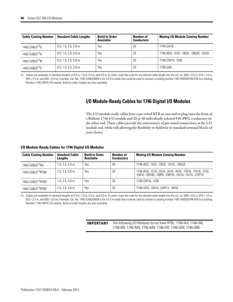
Publication 1747-SG001E-EN-E - February 2013
46 Select SLC 500 I/O Modules
I/O Module-Ready Cables for 1746 Digital I/O Modules
The I/O module-ready cables have a pre-wired RTB on one end to plug onto the front of a Bulletin 1746 I/O module and 20 or 40 individually colored #18 AWG conductors on the other end. These cables provide the convenience of pre-wired connections at the I/O module end, while still allowing the flexibility to fieldwire to standard terminal blocks of your choice.
1492-CABLE(1)G 0.5, 1.0, 2.5, 5.0 m Yes 20 1746-OA16
1492-CABLE(1)H 0.5, 1.0, 2.5, 5.0 m Yes 20 1746-IB32, -IV32, -OB32, -OB32E, -OV32
1492-CABLE(1)N 0.5, 1.0, 2.5, 5.0 m Yes 20 1746-OW16, -OX8
1492-CABLE(1)S 0.5, 1.0, 2.5, 5.0 m Yes 20 1746-OX8
(1) Cables are available in standard lengths of 0.5 m, 1.0 m, 2.5 m, and 5.0 m. To order, insert the code for the desired cable length into the cat. no. (005 = 0.5 m, 010 = 1.0 m, 025 = 2.5 m, and 050 = 5.0 m). Example: Cat. No. 1492-CABLE005N is for a 0.5 m cable that could be used to connect a catalog number 1492-IFM20D24N IFM to a Catalog Number 1746-OW16 I/O module. Build-to-order lengths are also available.
Cable Catalog Number Standard Cable Lengths Build to Order Available
Number of Conductors
Mating I/O Module Catalog Number
I/O Module-Ready Cables for 1746 Digital I/O Modules
Cable Catalog Number Standard Cable Lengths
Build to Order Available
Number of Conductors
Mating I/O Module Catalog Number
1492-CABLE(1)N3 1.0, 2.5, 5.0 m Yes 40 1746-IB32, -IV32, -OB32, -OV32, -OB32E
1492-CABLE(1)RTBB 1.0, 2.5, 5.0 m Yes 20 1746-IB16, -IC16, -IG16, -IH16, -IN16, -ITB16, -ITV16, -IV16, -OB16, -OB16E, -OBP8, -OBP16, -OG16, -OV16, -OVP16
1492-CABLE(1)RTBO 1.0, 2.5, 5.0 m Yes 20 1746-OW16, -OX8
1492-CABLE(1)RTBR 1.0, 2.5, 5.0 m Yes 20 1746-IA16, -OA16, -OAP12, -IM16
(1) Cables are available in standard lengths of 0.5 m, 1.0 m, 2.5 m, and 5.0 m. To order, insert the code for the desired cable length into the cat. no. (005 = 0.5 m, 010 = 1.0 m, 025 = 2.5 m, and 050 = 5.0 m). Example: Cat. No. 1492-CABLE005N is for a 0.5 m cable that could be used to connect a catalog number 1492-IFM20D24N IFM to a Catalog Number 1746-OW16 I/O module. Build-to-order lengths are also available.
IMPORTANT The following I/O Modules do not have RTBs: 1746-IA4, 1746-IA8, 1746-IB8, 1746-IM4, 1746-IM8, 1746-IV8, 1746-OA8, 1746-OB8.
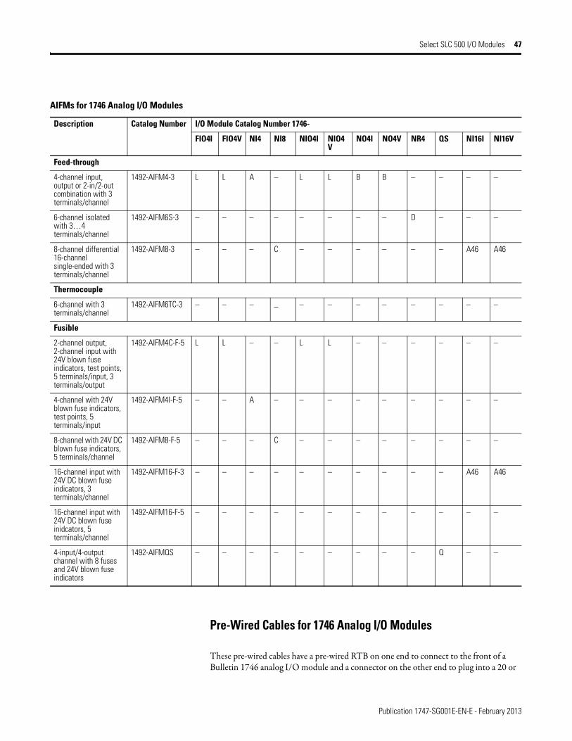
Publication 1747-SG001E-EN-E - February 2013
Select SLC 500 I/O Modules 47
Pre-Wired Cables for 1746 Analog I/O Modules
These pre-wired cables have a pre-wired RTB on one end to connect to the front of a Bulletin 1746 analog I/O module and a connector on the other end to plug into a 20 or
AIFMs for 1746 Analog I/O Modules
Description Catalog Number I/O Module Catalog Number 1746-
FIO4I FIO4V NI4 NI8 NIO4I NIO4V
NO4I NO4V NR4 QS NI16I NI16V
Feed-through
4-channel input, output or 2-in/2-out combination with 3 terminals/channel
1492-AIFM4-3 L L A – L L B B – – – –
6-channel isolated with 3…4 terminals/channel
1492-AIFM6S-3 – – – – – – – – D – – –
8-channel differential 16-channel single-ended with 3 terminals/channel
1492-AIFM8-3 – – – C – – – – – – A46 A46
Thermocouple
6-channel with 3 terminals/channel
1492-AIFM6TC-3 – – – – – – – – – – – –
Fusible
2-channel output, 2-channel input with 24V blown fuse indicators, test points, 5 terminals/input, 3 terminals/output
1492-AIFM4C-F-5 L L – – L L – – – – – –
4-channel with 24V blown fuse indicators, test points, 5 terminals/input
1492-AIFM4I-F-5 – – A – – – – – – – – –
8-channel with 24V DC blown fuse indicators, 5 terminals/channel
1492-AIFM8-F-5 – – – C – – – – – – – –
16-channel input with 24V DC blown fuse indicators, 3 terminals/channel
1492-AIFM16-F-3 – – – – – – – – – – A46 A46
16-channel input with 24V DC blown fuse inidcators, 5 terminals/channel
1492-AIFM16-F-5 – – – – – – – – – – – –
4-input/4-output channel with 8 fuses and 24V blown fuse indicators
1492-AIFMQS – – – – – – – – – Q – –
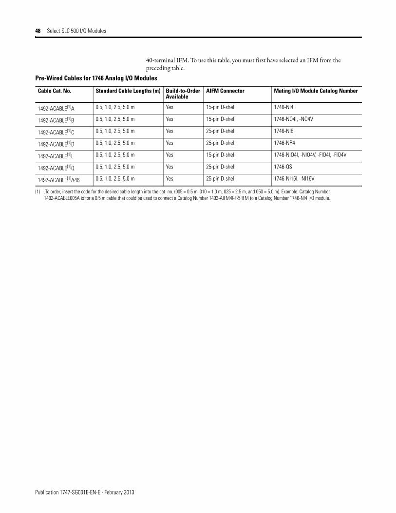
Publication 1747-SG001E-EN-E - February 2013
48 Select SLC 500 I/O Modules
40-terminal IFM. To use this table, you must first have selected an IFM from the preceding table.
Pre-Wired Cables for 1746 Analog I/O Modules
Cable Cat. No. Standard Cable Lengths (m) Build-to-Order Available
AIFM Connector Mating I/O Module Catalog Number
1492-ACABLE(1)A 0.5, 1.0, 2.5, 5.0 m Yes 15-pin D-shell 1746-NI4
1492-ACABLE(1)B 0.5, 1.0, 2.5, 5.0 m Yes 15-pin D-shell 1746-NO4I, -NO4V
1492-ACABLE(1)C 0.5, 1.0, 2.5, 5.0 m Yes 25-pin D-shell 1746-NI8
1492-ACABLE(1)D 0.5, 1.0, 2.5, 5.0 m Yes 25-pin D-shell 1746-NR4
1492-ACABLE(1)L 0.5, 1.0, 2.5, 5.0 m Yes 15-pin D-shell 1746-NIO4I, -NIO4V, -FIO4I, -FIO4V
1492-ACABLE(1)Q 0.5, 1.0, 2.5, 5.0 m Yes 25-pin D-shell 1746-QS
1492-ACABLE(1)A46 0.5, 1.0, 2.5, 5.0 m Yes 25-pin D-shell 1746-NI16I, -NI16V
(1) .To order, insert the code for the desired cable length into the cat. no. (005 = 0.5 m, 010 = 1.0 m, 025 = 2.5 m, and 050 = 5.0 m). Example: Catalog Number 1492-ACABLE005A is for a 0.5 m cable that could be used to connect a Catalog Number 1492-AIFM4I-F-5 IFM to a Catalog Number 1746-NI4 I/O module.

Publication 1747-SG001E-EN-E - February 2013
Select SLC 500 I/O Modules 49

Publication 1747-SG001E-EN-E - February 2013
50 Select SLC 500 I/O Modules
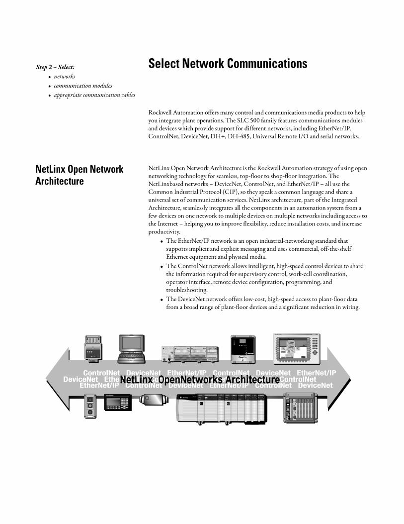
Select Network Communications
Rockwell Automation offers many control and communications media products to help you integrate plant operations. The SLC 500 family features communications modules and devices which provide support for different networks, including EtherNet/IP, ControlNet, DeviceNet, DH+, DH-485, Universal Remote I/O and serial networks.
NetLinx Open Network Architecture
NetLinx Open Network Architecture is the Rockwell Automation strategy of using open networking technology for seamless, top-floor to shop-floor integration. The NetLinxbased networks – DeviceNet, ControlNet, and EtherNet/IP – all use the Common Industrial Protocol (CIP), so they speak a common language and share a universal set of communication services. NetLinx architecture, part of the Integrated Architecture, seamlessly integrates all the components in an automation system from a few devices on one network to multiple devices on multiple networks including access to the Internet – helping you to improve flexibility, reduce installation costs, and increase productivity.
• The EtherNet/IP network is an open industrial-networking standard that supports implicit and explicit messaging and uses commercial, off-the-shelf Ethernet equipment and physical media.
• The ControlNet network allows intelligent, high-speed control devices to share the information required for supervisory control, work-cell coordination, operator interface, remote device configuration, programming, and troubleshooting.
• The DeviceNet network offers low-cost, high-speed access to plant-floor data from a broad range of plant-floor devices and a significant reduction in wiring.
Step 2 – Select:• networks• communication modules• appropriate communication cables
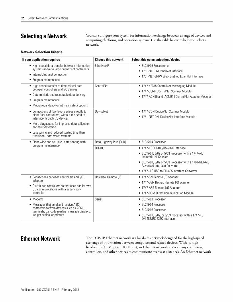
Publication 1747-SG001E-EN-E - February 2013
52 Select Network Communications
Selecting a Network You can configure your system for information exchange between a range of devices and computing platforms, and operation systems. Use the table below to help you select a network.
Ethernet Network The TCP/IP Ethernet network is a local-area network designed for the high-speed exchange of information between computers and related devices. With its high bandwidth (10 Mbps to 100 Mbps), an Ethernet network allows many computers, controllers, and other devices to communicate over vast distances. An Ethernet network
Network Selection Criteria
If your application requires Choose this network Select this communication / device
• High-speed data transfer between information systems and/or a large quantity of controllers
• Internet/Intranet connection
• Program maintenance
EtherNet/IP • SLC 5/05 Processor, or
• 1761-NET-ENI EtherNet Interface
• 1761-NET-ENIW Web-Enabled EtherNet Interface
• High-speed transfer of time-critical data between controllers and I/O devices
• Deterministic and repeatable data delivery
• Program maintenance
• Media redundancy or intrinsic safety options
ControlNet • 1747-KFC15 ControlNet Messaging Module
• 1747-SCNR ControlNet Scanner Module
• 1747-ACN15 and -ACNR15 ControlNet Adapter Modules
• Connections of low-level devices directly to plant floor controllers, without the need to interface through I/O devices
• More diagnostics for improved data collection and fault detection
• Less wiring and reduced startup time than traditional, hard-wired systems
DeviceNet • 1747-SDN DeviceNet Scanner Module
• 1761-NET-DNI DeviceNet Interface Module
• Plant-wide and cell-level data sharing with program maintenance
Data Highway Plus (DH+) • SLC 5/04 Processor
DH-485 • 1747-KE DH-485/RS-232C Interface
• SLC 5/01, 5/02 or 5/03 Processor with a 1747-AIC Isolated Link Coupler
• SLC 5/01, 5/02 or 5/03 Processor with a 1761-NET-AIC Advanced Interface Converter
• 1747-UIC USB to DH-485 Interface Converter
• Connections between controllers and I/O adapters
• Distributed controllers so that each has its own I/O communications with a supervisory controller
Universal Remote I/O • 1747-SN Remote I/O Scanner
• 1747-BSN Backup Remote I/O Scanner
• 1747-ASB Remote I/O Adapter
• 1747-DCM Direct Communication Module
• Modems
• Messages that send and receive ASCII characters to/from devices such as ASCII terminals, bar code readers, message displays, weight scales, or printers
Serial • SLC 5/03 Processor
• SLC 5/04 Processor
• SLC 5/05 Processor
• SLC 5/01, 5/02, or 5/03 Processor with a 1747-KE DH-485/RS-232C Interface

Publication 1747-SG001E-EN-E - February 2013
Select Network Communications 53
provides enterprise-wide systems access to plant-floor data. With an Ethernet network, you can maximize communication between a wide variety of equipment.
Ethernet connectivity for SLC 500 is provided for the following:• SLC 5/05 processor• 1761-NET-ENI/1761-NET-ENIW
MicroLogix 1000 controllers may be used with the 1761-NET-ENI, or -ENIW, however some features are not supported:
• Email (ENI/ENIW)• Controller store/download of device configuration (ENI/ENIW)• Floating point value display (ENIW)• Floating point value write from the device to the controller (ENIW)• Integer value write from the device to the controller (ENIW)• String file display (ENIW)
Ethernet Interface (ENI) and Web-Enabled Ethernet Interface (ENIW)
The 1761-NET-ENI module provides EtherNet/IP Messaging connectivity for all DF1 full-duplex devices. The ENI allows users to easily connect SLC 5/03 and SLC 5/04 controllers onto new or existing Ethernet networks and upload/download programs, communicate between controllers, and generate E-mail messages via SMTP (simple mail transport protocol).
Compatible devices include: MicroLogix 1000/1200/1500, PLC-5, ControlLogix, CompactLogix, and FlexLogix controllers, and computers running RSLinx.
The 1761-NET-ENIW module adds web-server capabilities, enabling the display of 4 standard data web pages with user-configurable data descriptions, and 10 userconfigurable web page links on the ENIW home page.
ETHERNET
FAULT
RS232
NET
TX/RX TX/RX
PWR
CABLE
EXTERNAL
IP
SLC 5/05 Controller
Ethernet Hub/Switch
MicroLogix 1500 Controller
1761-NET-ENI
Module
PC Ethernet
Interface Card
PC with
RSLogix 500
and RSLinx
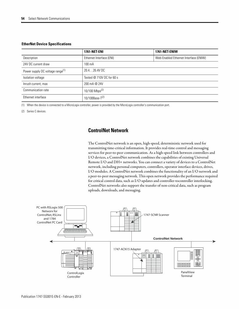
Publication 1747-SG001E-EN-E - February 2013
54 Select Network Communications
ControlNet Network
The ControlNet network is an open, high-speed, deterministic network used for transmitting time-critical information. It provides real-time control and messaging services for peer-to-peer communication. As a high-speed link between controllers and I/O devices, a ControlNet network combines the capabilities of existing Universal Remote I/O and DH+ networks. You can connect a variety of devices to a ControlNet network, including personal computers, controllers, operator interface devices, drives, I/O modules. A ControlNet network combines the functionality of an I/O network and a peer-to-peer messaging network. This open network provides the performance required for critical control data, such as I/O updates and controller-tocontroller interlocking. ControlNet networks also support the transfer of non-critical data, such as program uploads, downloads, and messaging.
EtherNet Device Specifications
1761-NET-ENI 1761-NET-ENIW
Description Ethernet Interface (ENI) Web-Enabled Ethernet Interface (ENIW)
24V DC current draw 100 mA
Power supply DC voltage range(1) 20.4…26.4V DC
Isolation voltage Tested @ 710V DC for 60 s
Inrush current, max 200 mA @ 24V
Communication rate 10/100 Mbps(2)
Ethernet interface 10/100Base-T(2)
(1) When the device is connected to a MicroLogix controller, power is provided by the MicroLogix controller's communication port.
(2) Series C devices.
ControlNet Network
PanelViewTerminal
ControlLogixController
1747-ACN15 Adapter
1747-SCNR Scanner
PC with RSLogix 500 Networx for
ControlNet, RSLinx and 1784
ControlNet PC Card

Publication 1747-SG001E-EN-E - February 2013
Select Network Communications 55
ControlNet network connectivity for SLC 500 is provided by the following:• 1747-KFC15 ControlNet Messaging Module• 1747-SCNR ControlNet Scanner• 1747-ACN15 and 1747-ACNR15 ControlNet Adapters
ControlNet Messaging Module
The 1747-KFC15 module provides the capability for an SLC 5/03, 5/04, and 5/05 processor to send or receive unscheduled ControlNet messages. With unscheduled messaging, the SLC controller program can send peer-to-peer messages or be accessed and edited over the ControlNet network using RSLogix 500 software. The 1747-KFC15 consumes 0.640 A @ 5V DC.
The ControlNet Messaging Module features:• 4-digit, 7-segment display for node address and module status.• RS-232 KFC to SLC cable (included).• media redundancy via dual BNC connectors.• power from the SLC chassis backplane.• ability to upgrade firmware via ControlFlash.
ControlNet Scanner Module
The 1747-SCNR module provides scheduled ControlNet network connections for SLC 5/02, 5/03, 5/04, and 5/05 processors. With scheduled messaging, the SLC processor can control I/O events in real time on the ControlNet network. The 1747-SCNR module can communicate with the 1771-PLC5C, 1756-Lx controllers, and with another 1747-SCNR module via scheduled messages on the ControlNet network. The 1747-SCNR module consumes 0.900 A @ 5V DC.
The ControlNet Scanner Module features:• media redundancy via dual BNC connectors.• ability to upgrade firmware via ControlFlash.
The 1747-SCNR module can control 1788-CN2DN and 1788-CN2FF linking devices as well as a variety of I/O platforms. The table below indicates with a “✓” which I/O platforms the 1747-SCNR module can control.
ControlNet Scanner I/O Control Capabilities
I/O Platform Discrete Analog
1746 ✓ ✓
1756
1771 ✓ ✓
Publication 1747-SG001E-EN-E - February 2013
56 Select Network Communications
ControlNet Adapter Modules
The 1747-ACN15 and -ACNR15 modules enable up to three 1746 chassis of I/O modules to produce/consume scheduled I/O on the ControlNet network. Both modules are compatible with all 1746 discrete, analog, and specialty I/O, except those requiring G-file configuration, such as the 1747-SN and 1747-BSN modules. The 1747-ACN15 and ACNR15 modules consume 0.9A at 5V dc.
The ControlNet Adapter Modules feature:• optional media redundancy via dual BNC connectors (1747-ACNR15).• individual connection to single modules or chassis connections to groups of
discrete modules.• ability to upgrade firmware via ControlFlash.
The table below indicates with a “✓” which ControlNet controllers can communicate to the 1747-ACN via scheduled messaging.
DeviceNet Network The DeviceNet network is an open, low-level communication link that provides connections between simple industrial devices like sensors and actuators to high-level devices like controllers. Based on standard Controller Area Network (CAN) technology, this open network offers inter-operability between like devices from multiple vendors. A DeviceNet network reduces installation costs, startup/commissioning time, and system or machine downtime.
The DeviceNet network provides:• inter-operability – simple devices from multiple vendors that meet DeviceNet
standards are interchangeable.• Common network - an open network provides common end-user solutions and
reduces the need to support a wide variety of device networks.• Lower maintenance costs – replace devices without disrupting other devices.
1793 ✓ ✓
1794 ✓ ✓
1797 ✓ ✓
ControlNet Scanner I/O Control Capabilities
I/O Platform Discrete Analog
ControlNet Adapter Communication Capabilities
ScheduledMessaging
1747-SCNR 1771-PLC5C 1756-Lx via 1756-CNB 1784-KTCS
1747-ACN(R)15Discrete I/O
✓ ✓ ✓
1747-ACN(R)15Analog I/O
✓ ✓
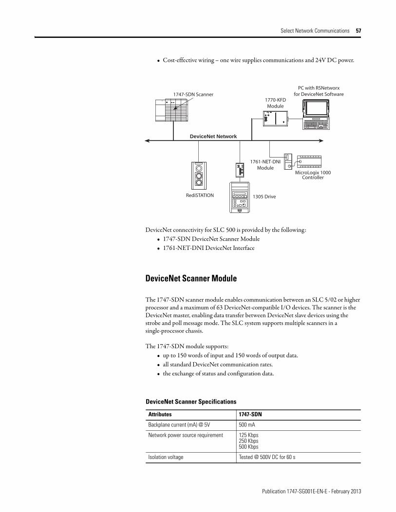
Publication 1747-SG001E-EN-E - February 2013
Select Network Communications 57
• Cost-effective wiring – one wire supplies communications and 24V DC power.
DeviceNet connectivity for SLC 500 is provided by the following:• 1747-SDN DeviceNet Scanner Module• 1761-NET-DNI DeviceNet Interface
DeviceNet Scanner Module
The 1747-SDN scanner module enables communication between an SLC 5/02 or higher processor and a maximum of 63 DeviceNet-compatible I/O devices. The scanner is the DeviceNet master, enabling data transfer between DeviceNet slave devices using the strobe and poll message mode. The SLC system supports multiple scanners in a single-processor chassis.
The 1747-SDN module supports:• up to 150 words of input and 150 words of output data.• all standard DeviceNet communication rates.• the exchange of status and configuration data.
1747-SDN Scanner 1770-KFDModule
1761-NET-DNIModule
1305 Drive RediSTATION
PC with RSNetworxfor DeviceNet Software
MicroLogix 1000Controller
DeviceNet Network
DeviceNet Scanner Specifications
Attributes 1747-SDN
Backplane current (mA) @ 5V 500 mA
Network power source requirement 125 Kbps250 Kbps500 Kbps
Isolation voltage Tested @ 500V DC for 60 s
Publication 1747-SG001E-EN-E - February 2013
58 Select Network Communications
Data Highway Plus (DH+) Network
The DH+ network is a local area network designed to support remote programming and data acquisition for factory-floor applications. You can also use DH+ communication modules to implement a peer-to-peer network.
The DH+ network supports daisy-chain and trunkline-dropline configurations. The number of supported devices on a DH+ link and the maximum length of the cable depends on the communication rate.
The table below shows the maximum cable lengths, communication rates and associated termination resistor sizes for the DH+ network.
Data Highway Plus connectivity for the SLC 500 is provided by the SLC 5/04 processor. See page 63 for more information on the SLC 5/04.
DH+ Network Specifications
Baud Rate Maximum Cable Distance
Terminating Resistor Size
57.6 K baud 3048 m (10,000 ft) 150 Ω
115 K baud 1542 m (5000 ft) 150 Ω
230.4 K baud 762 m (2500 ft) 82 Ω
DH+ Network
PC with 1784-PKTX
or -PKTXD
PLC-5 Controller
PLC-5 Controller
with 1785-KA5
SLC 5/04
1747-NET-AIC
Module
1747-AIC Module1747-AIC
Module
SLC 5/02 Controller SLC 5/03 Controller
Publication 1747-SG001E-EN-E - February 2013
Select Network Communications 59
DH-485 Network The DH-485 communication network allows devices on the plant floor to share information. Via the network, application programs can:
• monitor process and device parameters and status, including fault and alarm detection.
• perform data acquisition.• perform supervisory control functions.• upload/download PLC programs over the network.
The network offers connection to up to 32 nodes, token passing access control, and the ability to add or remove nodes without disrupting the network. DH-485 supports slave devices and features multiple-master capability.
The SLC 500 family includes the following DH-485 devices:• 1747-KE DH-485/RS-232C Interface Module• 1761-NET-AIC Advanced Interface Converter• 1747-AIC Isolated Link Coupler• 1747-UIC USB to DH-485 Converter
DH-485/RS-232C Interface Module
The 1747-KE module is a communication interface that acts as a bridge between DH-485 networks and RS-232C devices using DF1 protocol. It allows you to access your SLC 500 processor through an RS-232C link. When used in an SLC 500 chassis with a modem, the 1747-KE module enables remote programming and troubleshooting of any single SLC 500 processor, remote communication to a DH-485 network of SLC 500 processors, and remote data collection from the data table of any SLC 500 processor. The interface module allows you to use the SLC 500 as a remote terminal unit.
PC with USB Port
PC
1747-UIC
Module
1747-AIC
Module
PanelView
TerminalSLC 5/02 Controller
SLC 5/03 Controller or higher
1747-AIC Module
1747-NET-AIC Module
24V dc
User Power
Publication 1747-SG001E-EN-E - February 2013
60 Select Network Communications
1761-NET-AIC Advanced Interface Converter (AIC+)
This device is an isolated RS-232 to RS-485 converter. It allows two RS-232 devices (SLC 5/03, SLC 5/04, SLC 5/05; MicroLogix 1000, 1200, and 1500; DTAM Micro; PanelView) to connect to the DH-485 network.
To protect connected devices, the coupler provides 1500V dc isolation between the communications cable and the attached SLC 500 controller and peripheral devices.
1747-AIC Isolated Link Coupler
The panel-mountable isolated link coupler is used to connect SLC 5/01, SLC 5/02, and SLC 5/03 processors to a DH-485 network. Where there are two or more SLC 500 processors on the link, one isolated link coupler is required for each processor.
When another device (DTAM or personal computer) is connected to an SLC 500 processor at a distance greater than 6.09 m (20 ft), an isolated link coupler must be connected at each end of the link. A 1747-C11 cable is included with the coupler for connection to the processor.
DH-485/RS-232C Interface Module
Attribute 1747-KE
Backplane current (mA) @ 5V(1)
(1) The 1747-KE module requires both 5V Dc and 24V DC power from the SLC backplane. The power consumption of the module must be taken into consideration when planning your SLC 500 system.
150 mA
Backplane current (mA) @ 24V(1) (2)
(2) If the 1747-AIC Link Coupler is connected to the 1747-KE module with a 1747-C10 cable, then the link coupler draws its power (85 mA @ 24V DC) through the module. Be sure to add this value to the current requirements for the 1747-KE when estimating the total requirements for your system. If the 1747-AIC Link Coupler is connected to the 1747-KE module with a 1747-C13 cable, the power for the link coupler comes from either an SLC 500 processor or an external power supply. Therefore, current requirements remain as listed.
40 mA
Real time clock/accuracy ±1 minute/month at 25 ° C (77 °F)+0, -6 minute/month at 60 ° C (140 °F)
Isolation voltage(1) (2) Tested @ 500V DC
Advanced Interface Converter (AIC+) Specifications
Attribute 1761-NET-AIC
24V DC current draw 120 mA
Inrush current, max. 200 mA @ 24V
24V DC power source requirement 20.4…28.8V DC
Isolation voltage Tested @ 500V DC for 60 s
Publication 1747-SG001E-EN-E - February 2013
Select Network Communications 61
1747-UIC Universal Serial Bus to DH-485 Interface Converter
This device allows a computer with a USB port to interface to DH-485 ports on an SLC 500, MicroLogix, or other Rockwell Automation controllers and on PanelView terminals. The 1747-UIC features a USB connector as well as both an RS-232 and an RS-485 port. Use the RS-232 port to connect to SLC 5/03, 5/04, 5/05 (Channel 0), MicroLogix, CompactLogix, FlexLogix, ControlLogix, PanelView 300 or higher, or AIC+. Use the RS-485 Port to connect to SLC 5/01, 5/02, 5/03 (Channel 1), PanelView 300 or higher, or 1747-AIC.
Universal Remote I/O (RIO) Network
The strength and versatility of the Universal Remote I/O network comes from the breadth of products it supports. In addition to 1746 I/O, the Universal Remote I/O network supports many Allen-Bradley and third-party devices.
Typical applications range from simple I/O links with controllers and I/O, to links with a wide variety of other types of devices. You connect devices through remote I/O adapter modules or built-in remote I/O adapters. Using the Universal RIO Network instead of direct-wiring a device over a long distance to a local I/O chassis reduces installation, start-up, and maintenance costs by placing the I/O closer to the sensors and actuators.
SLC 5/03, 5/04, and 5/05 processors support pass-thru which lets you configure RIO devices remotely from an Ethernet, DH+, or DH-485/DF1 network, as well as block transfer instructions for faster reading and writing of I/O data.
Universal Remote I/O Connectivity for SLC 500 is provided by the following interfaces:
USB to DH-485 Interface Converter Specifications
Attribute 1747-UIC
USB power consumption <100 mA (low power)
USB speed USB 1.1 (12 Mbps)
DH-485 Baud Rate 19.2 Kbps
SLC 5/03 Controller SLC 5/04 Controller SLC 5/02 Controller
PanelView Terminal
Block I/O
Remote I/O Network
1747-SN Module
1747-DCM
Module
1747-ASB
Module

Publication 1747-SG001E-EN-E - February 2013
62 Select Network Communications
• 1747-SN Remote I/O Scanner• 1747-BSN Backup Remote I/O Scanner• 1747-ASB Remote I/O Adapter• 1747-DCM Direct Communication Module
RS-232/DF1 Port Splitters Remote I/O Scanner Module
The 1747-SN module provides high-speed remote communication between an SLC processor and Allen-Bradley operator interface and control devices. The scanner provides connectivity of your SLC 5/02 or higher processor to devices such as InView Message displays, Power Monitor 3000, PanelView, 1791 Block I/O, Allen-Bradley Drives, 1746 I/O, 1771 I/O, and Flex I/O devices.
Note: The series B scanner supports block transfer of up to 64 words of data.
The 1747-SN features:• noise immunity over various cable distances via selectable baud rates.• distribution of devices over a wide physical area, supporting RIO cable lengths up
to 3050 m (10,000 ft).• connection of up to 16 devices in normal mode or 32 devices in complementary
mode.• capability to send large amounts of data to RIO devices without affecting system
throughput, utilizing block transfers.• capability to download and change applications in PanelView terminals and
Power monitors via remote I/O passthru.
Backup Scanner Module
High Speed Serial Link
1747-BSNModule
1747-BSNModule
RIONetwork
RIO Network
1747-ASB Module
Publication 1747-SG001E-EN-E - February 2013
Select Network Communications 63
The 1747-BSN module contains the full complement of RIO scanner features, plus backup capability for support of redundant processor applications. The backup system consists of one or more pairs of complementary modules, with one module residing in the primary system and the other in the backup system. The primary system controls the operation of remote I/O, while the backup system monitors communications via the high-speed serial link (HSSL) and is available to take control in the event of a fault in the primary system.
The 1747-BSN features:• backup of one Remote I/O or DH+ network per complementary BSN module
pair.• backup of one RS-232/DH-485 communications per complentary BSN module
pair,• allowing HMIs on channel 0 to automatically transfer to the primary processor.• transfer of up to 2 K words of retentive data per BSN.• repair of primary system fault during secondary backup system operation.• remote programming capability of secondary processor on DH+ (SLC 5/04
only).• minimal user program impact.• backup system diagnostic information.
Remote I/O Adapter Module
The 1747-ASB module provides a communication link between SLC or PLC scanners and a wide variety of 1746 I/O modules over the Remote I/O link. The module maps the image of the I/O modules in its remote chassis directly to the SLC or PLC image table.
The 1747-ASB module features:• support for both discrete and block transfer image mapping.• efficient image utilization with support for 1/2-slot, 1-slot, and 2-slot addressing.
Direct Communication Module
The 1747-DCM module links the SLC 500 controller to the Allen-Bradley PLC for distributed processing. The DCM acts as a remote I/O adapter on a remote I/O link.
Information is transferred between a local PLC or SLC scanner and a remote 1747-DCM module during each remote I/O scan. The number of DCMs that a scanner can supervise depends on the number of chassis the scanner supports and the chassis size of the DCM. The SLC 500 module controllers support multiple DCMs.
Note: An important distinction between a DCM module and the 1747-ASB module is that a DCM is placed in the chassis with the processor and it does not scan any I/O in the chassis as an ASB module does.
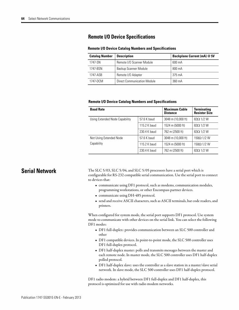
Publication 1747-SG001E-EN-E - February 2013
64 Select Network Communications
Remote I/O Device Specifications
Serial Network The SLC 5/03, SLC 5/04, and SLC 5/05 processors have a serial port which is configurable for RS-232 compatible serial communication. Use the serial port to connect to devices that:
• communicate using DF1 protocol, such as modems, communication modules, programming workstations, or other Encompass partner devices.
• communicate using DH-485 protocol.• send and receive ASCII characters, such as ASCII terminals, bar code readers, and
printers.
When configured for system mode, the serial port supports DF1 protocol. Use system mode to communicate with other devices on the serial link. You can select the following DF1 modes:
• DF1 full-duplex: provides communication between an SLC 500 controller and other
• DF1 compatible devices. In point-to-point mode, the SLC 500 controller uses DF1 full-duplex protocol.
• DF1 half-duplex master: polls and transmits messages between the master and each remote node. In master mode, the SLC 500 controller uses DF1 half-duplex polled protocol.
• DF1 half-duplex slave: uses the controller as a slave station in a master/slave serial network. In slave mode, the SLC 500 controller uses DF1 half-duplex protocol.
DF1 radio modem: a hybrid between DF1 full-duplex and DF1 half-duplex, this protocol is optimized for use with radio modem networks.
Remote I/O Device Catalog Numbers and Specifications
Catalog Number Description Backplane Current (mA) @ 5V
1747-SN Remote I/O Scanner Module 600 mA
1747-BSN Backup Scanner Module 800 mA
1747-ASB Remote I/O Adapter 375 mA
1747-DCM Direct Communication Module 360 mA
Remote I/O Device Catalog Numbers and Specifications
Baud Rate Maximum Cable Distance
Terminating Resistor Size
Using Extended Node Capability 57.6 K baud 3048 m (10,000 ft) 82Ω 1/2 W
115.2 K baud 1524 m (5000 ft) 82Ω 1/2 W
230.4 K baud 762 m (2500 ft) 82Ω 1/2 W
Not Using Extended Node
Capability
57.6 K baud 3048 m (10,000 ft) 150Ω 1/2 W
115.2 K baud 1524 m (5000 ft) 150Ω 1/2 W
230.4 K baud 762 m (2500 ft) 82Ω 1/2 W
Publication 1747-SG001E-EN-E - February 2013
Select Network Communications 65
In system mode, the serial port also supports supervisory control and data acquisition (SCADA) applications. SCADA systems allow you to monitor and control remote functions and processes using serial communication links between master and slave locations.
When configured for user mode, the serial port supports ASCII devices. Use the SLC 500 ASCII instructions to send information to and receive information from these devices.
RS-232/DF1 Port Splitters
The 1747 Port Splitters let a single RS-232/DF1 full-duplex communication port on a controller split into two separate ports for simultaneous connection with two external devices. The Port Splitter supports the following: SLC 500, PLC-5, MicroLogix, ControlLogix, CompactLogix, and FlexLogix controllers.
The Port Splitter has three ports for Controller, Network and Programmer/HMI connections. It also has a connection for a +24V external power source and status LEDs.
• The Controller port connects to the RS-232/DF1 full-duplex port of a controller. The port configuration is set at DF1 full-duplex, 8 bits, no parity, 1 stop bit and CRC checksum on powerup. The port automatically sets the baud rate to 19.2 K or 38.4 K baud taking advantage of the controller's maximum baud rate and can also match the controller's CRC or BCC checksum.
• The Network port on the 1747-DPS1 connects to a 1761-NET-AIC, 1761-NET-DNI or 1761-NET-ENI module and receives any messages initiated from the controller. The network port can source power from the port splitter's external power supply to one of the above modules if a 1761-CBL-AM00 or 1761-CBL-HM02 cable is used.
• The Network port on the 1747-DPS2 provides similar functionality, but can be configured for communications with DH-485, DF1 half-duplex (master or slave), DF1 full-duplex, and DF1 radio modem networks. The port is programmed for DH-485 communication at the factory.
• The 1747-DPS2 port splitter has fully-isolated communication ports. Therefore, no external isolation is required.
• The Prog/HMI port connects to a programming station or HMI device (PanelView Standard, PanelView Plus, VersaView CE) for respond only operations.
The serial configuration for the Network and Programmer/HMI ports on the 1747-DPS1 port splitter must be set to DF1 full-duplex, 8 bits, no parity, 1 stop bit, 19.2 K baud and CRC checksum.
The Network port on the 1747-DPS2 port splitter can be configured forwonderduplex, and DF1 radio modem networks.

Publication 1747-SG001E-EN-E - February 2013
66 Select Network Communications
Communication Cables The following tables provide a description of available communication cables and a summary of cable connectivity.
MicroLogix 1500 Controller
or other Controller with
RS-232/DF1 Full-Duplex Port)
SLC 5/03, 5/04, 5/05 Channel 0
(or other controller with
RS-232/DF1 Full-Duplex Port)
Ethernet/IP Network
Operator Interface
RS-232/DF1 Port Splitter
1761-NET-AIC
Module
DeviceNet Network
PC/Programming Terminal
24V dc, 100 mA,
Class 2 Power Supply
Communication Cables
Catalog Number Description
1761-CBL-AC00 SLC 5/03, 5/04, and 5/05 Communication Cable - This 45 cm (17.7 in) cable has two 9-pin DTE connectors and is used to connect the SLC 5/03, 5/04, or 5/05 processor RS-232 channel (channel 0) to port 1 of the 1761-NET-AIC.
1761-CBL-AP00 SLC 5/03, 5/04, and 5/05 Communication Cable - This 45 cm (17.7 in) cable has a 9-pin DTE and an 8-pin mini DIN connector and is used to connect the SLC 5/03, 5/04, or 5/05 processor RS-232 channel (channel 0) to port 2 of the 1761-NET-AIC.
1761-CBL-PM02 SLC 5/03, 5/04, and 5/05 Communication Cable - This 2 m (6.5 ft) cable has a 9-pin DTE and an 8-pin mini DIN connector and is used to connect the SLC 5/03, 5/04, or SLC 5/05 processor RS-232 channel (channel 0) to port 2 of the 1761-NET-AIC.
1761-CBL-AS03 RJ45 to 6-Pin Phoenix Connector Communication Cable - This 3 m (9.8 ft) cable is used to connect the SLC 5/01, SLC 5/02, and SLC 5/03 processor RJ45 port to port 3 of the 1761-NET-AIC.
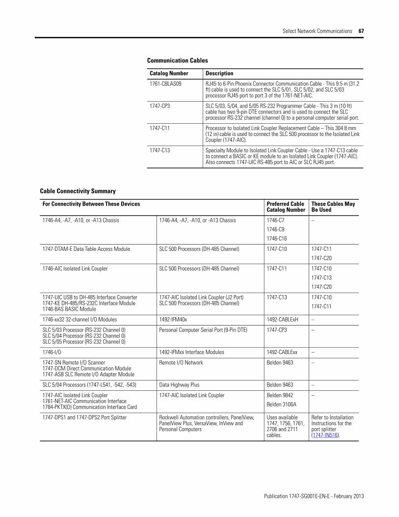
Publication 1747-SG001E-EN-E - February 2013
Select Network Communications 67
1761-CBLAS09 RJ45 to 6-Pin Phoenix Connector Communication Cable - This 9.5 m (31.2 ft) cable is used to connect the SLC 5/01, SLC 5/02, and SLC 5/03 processor RJ45 port to port 3 of the 1761-NET-AIC.
1747-CP3 SLC 5/03, 5/04, and 5/05 RS-232 Programmer Cable - This 3 m (10 ft) cable has two 9-pin DTE connectors and is used to connect the SLC processor RS-232 channel (channel 0) to a personal computer serial port.
1747-C11 Processor to Isolated Link Coupler Replacement Cable – This 304.8 mm (12 in) cable is used to connect the SLC 500 processor to the Isolated Link Coupler (1747-AIC).
1747-C13 Specialty Module to Isolated Link Coupler Cable - Use a 1747-C13 cable to connect a BASIC or KE module to an Isolated Link Coupler (1747-AIC). Also connects 1747-UIC RS-485 port to AIC or SLC RJ45 port.
Communication Cables
Catalog Number Description
Cable Connectivity Summary
For Connectivity Between These Devices Preferred Cable Catalog Number
These Cables May Be Used
1746-A4, -A7, -A10, or -A13 Chassis 1746-A4, -A7, -A10, or -A13 Chassis 1746-C7
1746-C9
1746-C16
–
1747-DTAM-E Data Table Access Module SLC 500 Processors (DH-485 Channel) 1747-C10 1747-C11
1747-C20
1746-AIC Isolated Link Coupler SLC 500 Processors (DH-485 Channel) 1747-C11 1747-C10
1747-C13
1747-C20
1747-UIC USB to DH-485 Interface Converter1747-KE DH-485/RS-232C Interface Module1746-BAS BASIC Module
1747-AIC Isolated Link Coupler (J2 Port)SLC 500 Processors (DH-485 Channel)
1747-C13 1747-C10
1747-C11
1746-xx32 32-channel I/O Modules 1492-IFM40x 1492-CABLExH –
SLC 5/03 Processor (RS-232 Channel 0)SLC 5/04 Processor (RS-232 Channel 0)SLC 5/05 Processor (RS-232 Channel 0)
Personal Computer Serial Port (9-Pin DTE) 1747-CP3 –
1746-I/O 1492-IFMxx Interface Modules 1492-CABLExx –
1747-SN Remote I/O Scanner1747-DCM Direct Communication Module1747-ASB SLC Remote I/O Adapter Module
Remote I/O Network Belden 9463 –
SLC 5/04 Processors (1747-L541, -542, -543) Data Highway Plus Belden 9463 –
1747-AIC Isolated Link Coupler1761-NET-AIC Communication Interface1784-PKTX(D) Communication Interface Card
1747-AIC Isolated Link Coupler Belden 9842
Belden 3106A
–
1747-DPS1 and 1747-DPS2 Port Splitter Rockwell Automation controllers, PanelView, PanelView Plus, VersaView, InView and Personal Computers
Uses available 1747, 1756, 1761, 2706 and 2711 cables.
Refer to Installation Instructions for the port splitter (1747-IN516).

Publication 1747-SG001E-EN-E - February 2013
68 Select Network Communications
Notes:
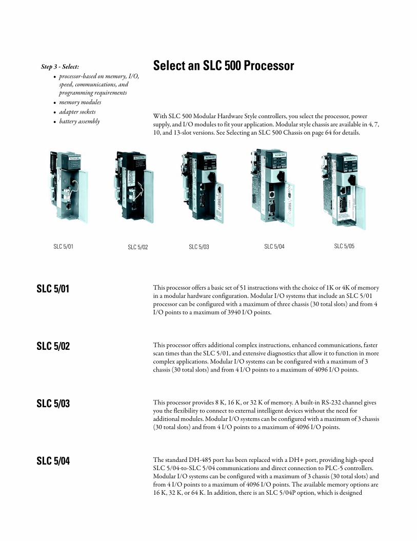
Select an SLC 500 Processor
With SLC 500 Modular Hardware Style controllers, you select the processor, power supply, and I/O modules to fit your application. Modular style chassis are available in 4, 7, 10, and 13-slot versions. See Selecting an SLC 500 Chassis on page 64 for details.
SLC 5/01 This processor offers a basic set of 51 instructions with the choice of 1K or 4K of memory in a modular hardware configuration. Modular I/O systems that include an SLC 5/01 processor can be configured with a maximum of three chassis (30 total slots) and from 4 I/O points to a maximum of 3940 I/O points.
SLC 5/02 This processor offers additional complex instructions, enhanced communications, faster scan times than the SLC 5/01, and extensive diagnostics that allow it to function in more complex applications. Modular I/O systems can be configured with a maximum of 3 chassis (30 total slots) and from 4 I/O points to a maximum of 4096 I/O points.
SLC 5/03 This processor provides 8 K, 16 K, or 32 K of memory. A built-in RS-232 channel gives you the flexibility to connect to external intelligent devices without the need for additional modules. Modular I/O systems can be configured with a maximum of 3 chassis (30 total slots) and from 4 I/O points to a maximum of 4096 I/O points.
SLC 5/04 The standard DH-485 port has been replaced with a DH+ port, providing high-speed SLC 5/04-to-SLC 5/04 communications and direct connection to PLC-5 controllers. Modular I/O systems can be configured with a maximum of 3 chassis (30 total slots) and from 4 I/O points to a maximum of 4096 I/O points. The available memory options are 16 K, 32 K, or 64 K. In addition, there is an SLC 5/04P option, which is designed
Step 3 - Select:• processor-based on memory, I/O,
speed, communications, and programming requirements
• memory modules• adapter sockets• battery assembly
SLC 5/01 SLC 5/02 SLC 5/03 SLC 5/04 SLC 5/05
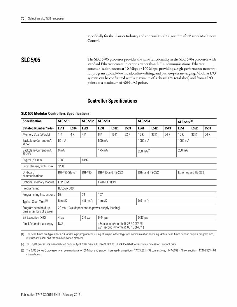
Publication 1747-SG001E-EN-E - February 2013
70 Select an SLC 500 Processor
specifically for the Plastics Industry and contains ERC2 algorithms forPlastics Machinery Control.
SLC 5/05 The SLC 5/05 processor provides the same functionality as the SLC 5/04 processor with standard Ethernet communications rather than DH+ communications. Ethernet communication occurs at 10 Mbps or 100 Mbps, providing a high performance network for program upload/download, online editing, and peer-to-peer messaging. Modular I/O systems can be configured with a maximum of 3 chassis (30 total slots) and from 4 I/O points to a maximum of 4096 I/O points.
Controller Specifications
SLC 500 Modular Controllers Specifications
Specification SLC 5/01 SLC 5/02 SLC 5/03 SLC 5/04 SLC 5/05(3)
Catalog Number 1747- L511 L514 L524 L531 L532 L533 L541 L542 L543 L551 L552 L553
Memory Size (Words) 1 K 4 K 4 K 8 K 16 K 32 K 16 K 32 K 64 K 16 K 32 K 64 K
Backplane Current (mA) @ 5V
90 mA 500 mA 1000 mA 1000 mA
Backplane Current (mA) @ 24V
0 mA 175 mA 200 mA(2) 200 mA
Digital I/O, max 7880 8192
Local chassis/slots, max. 3/30
On-board communications
DH-485 Slave DH-485 DH-485 and RS-232 DH+ and RS-232 Ethernet and RS-232
Optional memory module EEPROM Flash EEPROM
Programming RSLogix 500
Programming Instructions 52 71 107
Typical Scan Time(1) 8 ms/K 4.8 ms/K 1 ms/K 0.9 ms/K
Program scan hold-up time after loss of power
20 ms…3 s (dependent on power supply loading)
Bit Execution (XIC) 4 μs 2.4 μs 0.44 μs 0.37 μs
Clock/calendar accuracy N/A ±54 seconds/month @ 25 °C (77 °F)±81 seconds/month @ 60 °C (140°F)
(1) The scan times are typical for a 1K ladder logic program consisting of simple ladder logic and communication servicing. Actual scan times depend on your program size, instructions used, and the communication protocol.
(2) SLC 5/04 processors manufactured prior to April 2002 draw 200 mA @ 24V dc. Check the label to verify your processor's current draw.
(3) The 5/05 Series C processors can communicate to 100 Mbps and support increased connections: 1747-L551 = 32 connections; 1747-L552 = 48 connections; 1747-L553 = 64 connections.
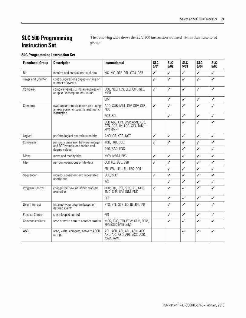
Publication 1747-SG001E-EN-E - February 2013
Select an SLC 500 Processor 71
SLC 500 Programming Instruction Set
The following table shows the SLC 500 instruction set listed within their functional groups.
SLC Programming Instruction Set
Functional Group Description Instruction(s) SLC 5/01
SLC 5/02
SLC 5/03
SLC 5/04
SLC 5/05
Bit monitor and control status of bits XIC, XIO, OTE, OTL, OTU, OSR ✓ ✓ ✓ ✓ ✓
Timer and Counter control operations based on time or number of events
✓ ✓ ✓ ✓ ✓
Compare compare values using an expression or specific compare instruction
EQU, NEQ, LES, LEQ, GRT, GEQ, MEQ
✓ ✓ ✓ ✓ ✓
LIM ✓ ✓ ✓ ✓
Compute evaluate arithmetic operations using an expression or specific arithmetic instruction
ADD, SUB, MUL, DIV, DDV, CLR, NEG
✓ ✓ ✓ ✓ ✓
SQR, SCL ✓ ✓ ✓ ✓
SCP, ABS, CPT, SWP, ASN, ACS, ATN, COS, LN, LOG, SIN, TAN, XPY, RMP
✓ ✓ ✓
Logical perform logical operations on bits AND, OR, XOR, NOT ✓ ✓ ✓ ✓ ✓
Conversion perform conversion between integer and BCD values, and radian and degree values
TOD, FRD, DCD ✓ ✓ ✓ ✓ ✓
DEG, RAD, ENC ✓ ✓ ✓
Move move and modify bits MOV, MVM, RPC ✓ ✓ ✓ ✓ ✓
File perform operations of file data COP, FLL, BSL, BSR ✓ ✓ ✓ ✓ ✓
FFL, FFU, LFL, LFU, FBC, DDT ✓ ✓ ✓ ✓
Sequencer monitor consistent and repeatable operations
SQO, SQC ✓ ✓ ✓ ✓ ✓
SQL ✓ ✓ ✓ ✓
Program Control change the flow of ladder program execution
JMP, LBL, JSR, SBR, RET, MCR, TND, SUS, IIM, IOM, END
✓ ✓ ✓ ✓ ✓
REF ✓ ✓ ✓ ✓
User Interrupt interrupt your program based on defined events
STD, STE, STS, IID, IIE, RPI, INT ✓ ✓ ✓ ✓
Process Control close-looped control PID ✓ ✓ ✓ ✓
Communications read or write data to another station MSG, SVC, BTR, BTW, CEM, DEM, EEM (SLC 5/05 only)
✓ ✓ ✓ ✓
ASCII read, write, compare, convert ASCII strings
ABL, ACB, ACI, ACL, ACN, AEX, AHL, AIC, ARD, ARL, ASC, ASR, AWA, AWT
✓ ✓ ✓
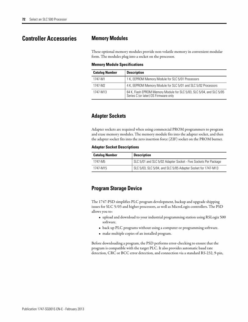
Publication 1747-SG001E-EN-E - February 2013
72 Select an SLC 500 Processor
Controller Accessories Memory Modules
These optional memory modules provide non-volatile memory in convenient modular form. The modules plug into a socket on the processor.
Adapter Sockets
Adapter sockets are required when using commercial PROM programmers to program and erase memory modules. The memory module fits into the adapter socket, and then the adapter socket fits into the zero insertion force (ZIF) socket on the PROM burner.
Program Storage Device
The 1747-PSD simplifies PLC program development, backup and upgrade shipping issues for SLC 5/03 and higher processors, as well as MicroLogix controllers. The PSD allows you to:
• upload and download to your industrial programming station using RSLogix 500 software.
• back up PLC programs without using a computer or programming software.• make multiple copies of an installed program.
Before downloading a program, the PSD performs error-checking to ensure that the program is compatible with the target PLC. It also provides automatic baud rate detection, CRC or BCC error detection, and connection via a standard RS-232, 9-pin,
Memory Module Specifications
Catalog Number Description
1747-M1 1 K, EEPROM Memory Module for SLC 5/01 Processors
1747-M2 4 K, EEPROM Memory Module for SLC 5/01 and SLC 5/02 Processors
1747-M13 64 K, Flash EPROM Memory Module for SLC 5/03, SLC 5/04, and SLC 5/05 Series C (or later) OS Firmware only
Adapter Socket Descriptions
Catalog Number Description
1747-M5 SLC 5/01 and SLC 5/02 Adapter Socket - Five Sockets Per Package
1747-M15 SLC 5/03, SLC 5/04, and SLC 5/05 Adapter Socket for 1747-M13
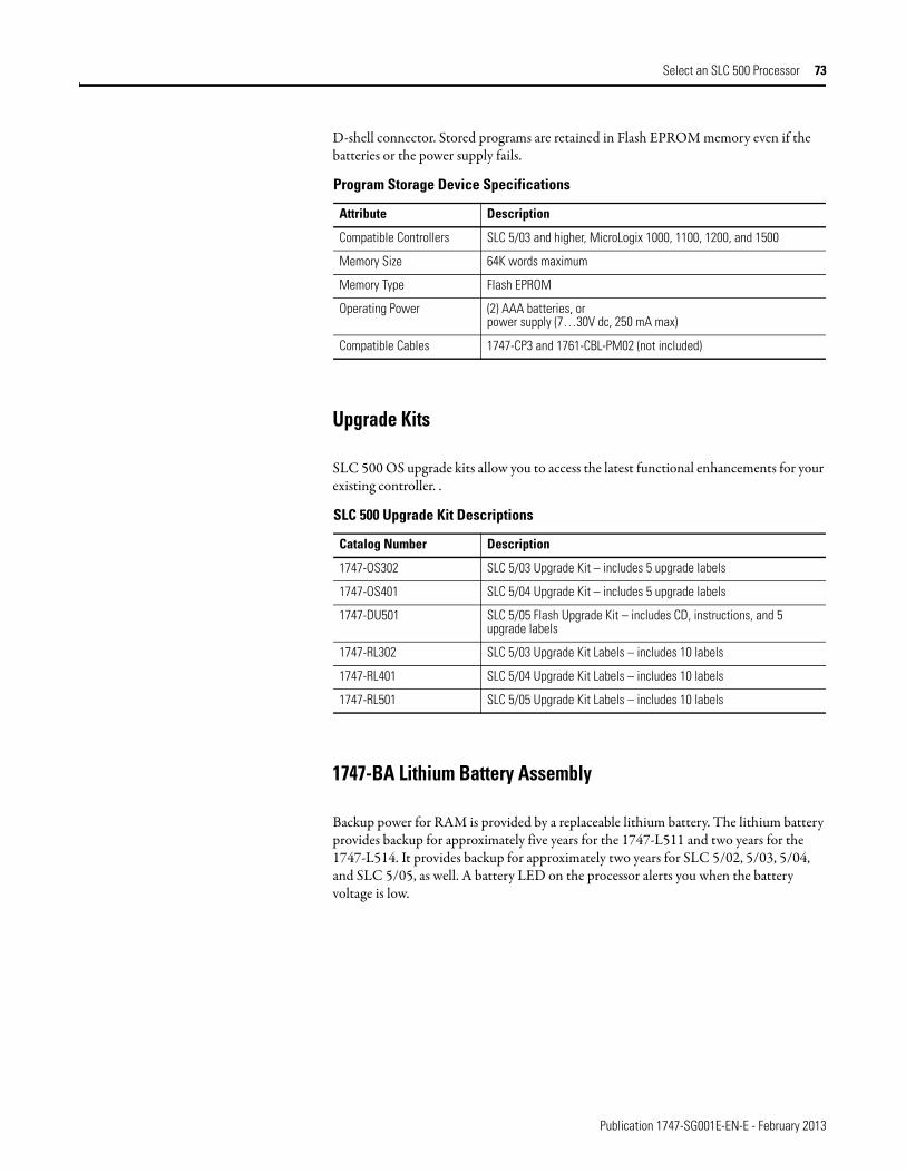
Publication 1747-SG001E-EN-E - February 2013
Select an SLC 500 Processor 73
D-shell connector. Stored programs are retained in Flash EPROM memory even if the batteries or the power supply fails.
Upgrade Kits
SLC 500 OS upgrade kits allow you to access the latest functional enhancements for your existing controller. .
1747-BA Lithium Battery Assembly
Backup power for RAM is provided by a replaceable lithium battery. The lithium battery provides backup for approximately five years for the 1747-L511 and two years for the 1747-L514. It provides backup for approximately two years for SLC 5/02, 5/03, 5/04, and SLC 5/05, as well. A battery LED on the processor alerts you when the battery voltage is low.
Program Storage Device Specifications
Attribute Description
Compatible Controllers SLC 5/03 and higher, MicroLogix 1000, 1100, 1200, and 1500
Memory Size 64K words maximum
Memory Type Flash EPROM
Operating Power (2) AAA batteries, orpower supply (7…30V dc, 250 mA max)
Compatible Cables 1747-CP3 and 1761-CBL-PM02 (not included)
SLC 500 Upgrade Kit Descriptions
Catalog Number Description
1747-OS302 SLC 5/03 Upgrade Kit – includes 5 upgrade labels
1747-OS401 SLC 5/04 Upgrade Kit – includes 5 upgrade labels
1747-DU501 SLC 5/05 Flash Upgrade Kit – includes CD, instructions, and 5 upgrade labels
1747-RL302 SLC 5/03 Upgrade Kit Labels – includes 10 labels
1747-RL401 SLC 5/04 Upgrade Kit Labels – includes 10 labels
1747-RL501 SLC 5/05 Upgrade Kit Labels – includes 10 labels

Publication 1747-SG001E-EN-E - February 2013
74 Select an SLC 500 Processor
Notes:
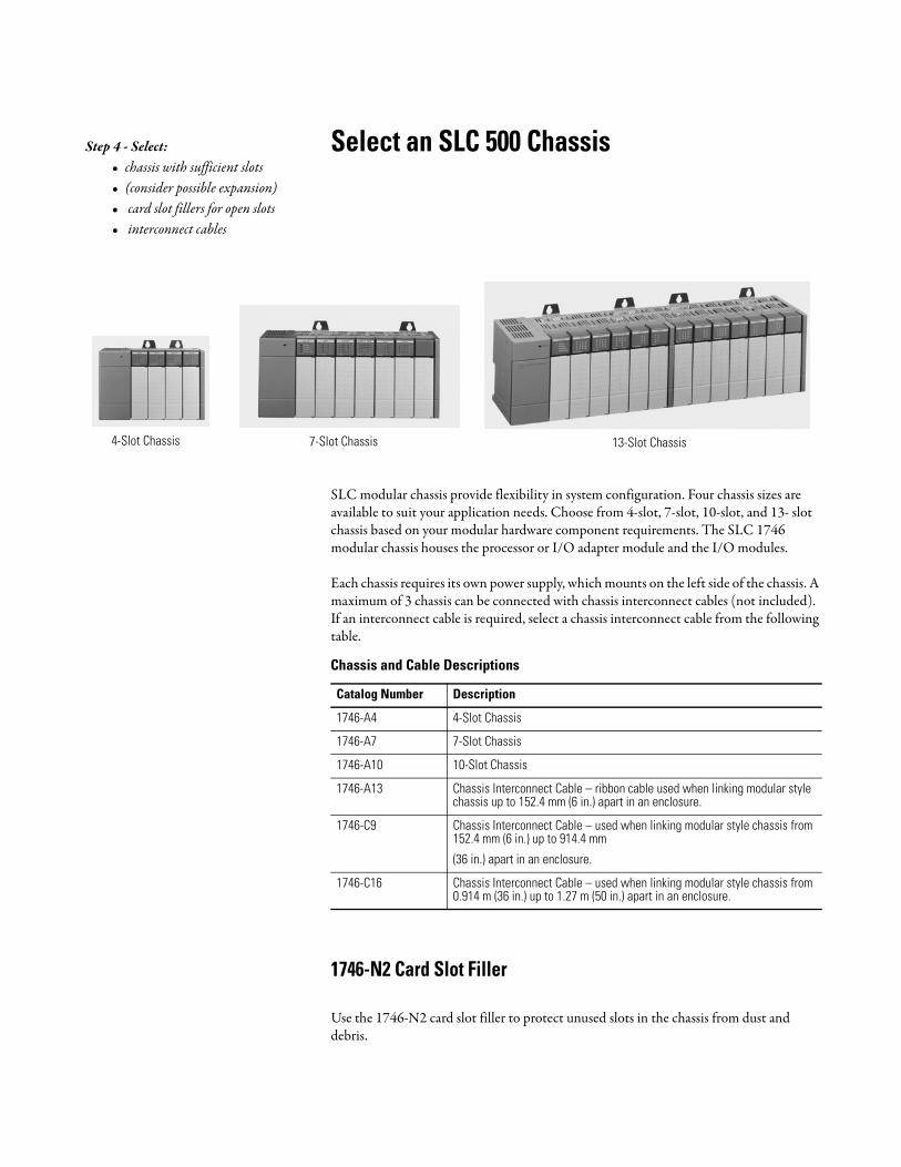
Select an SLC 500 Chassis
SLC modular chassis provide flexibility in system configuration. Four chassis sizes are available to suit your application needs. Choose from 4-slot, 7-slot, 10-slot, and 13- slot chassis based on your modular hardware component requirements. The SLC 1746 modular chassis houses the processor or I/O adapter module and the I/O modules.
Each chassis requires its own power supply, which mounts on the left side of the chassis. A maximum of 3 chassis can be connected with chassis interconnect cables (not included). If an interconnect cable is required, select a chassis interconnect cable from the following table.
1746-N2 Card Slot Filler
Use the 1746-N2 card slot filler to protect unused slots in the chassis from dust and debris.
Step 4 - Select:• chassis with sufficient slots• (consider possible expansion)• card slot fillers for open slots• interconnect cables
4-Slot Chassis 7-Slot Chassis 13-Slot Chassis
Chassis and Cable Descriptions
Catalog Number Description
1746-A4 4-Slot Chassis
1746-A7 7-Slot Chassis
1746-A10 10-Slot Chassis
1746-A13 Chassis Interconnect Cable – ribbon cable used when linking modular style chassis up to 152.4 mm (6 in.) apart in an enclosure.
1746-C9 Chassis Interconnect Cable – used when linking modular style chassis from 152.4 mm (6 in.) up to 914.4 mm
(36 in.) apart in an enclosure.
1746-C16 Chassis Interconnect Cable – used when linking modular style chassis from 0.914 m (36 in.) up to 1.27 m (50 in.) apart in an enclosure.
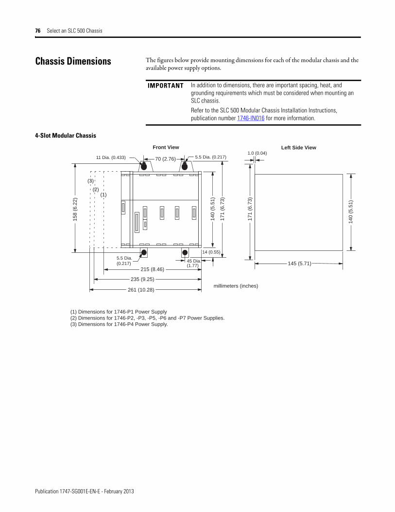
Publication 1747-SG001E-EN-E - February 2013
76 Select an SLC 500 Chassis
Chassis Dimensions The figures below provide mounting dimensions for each of the modular chassis and the available power supply options.
4-Slot Modular Chassis
IMPORTANT In addition to dimensions, there are important spacing, heat, and grounding requirements which must be considered when mounting an SLC chassis.
Refer to the SLC 500 Modular Chassis Installation Instructions, publication number 1746-IN016 for more information.
261 (10.28)
235 (9.25)
215 (8.46)145 (5.71)
17
1 (
6.7
3)
14
0 (
5.5
1)
15
8 (
6.2
2)
14
0 (
5.5
1)
17
1 (
6.7
3)
70 (2.76)
14 (0.55)
11 Dia. (0.433) 5.5 Dia. (0.217)1.0 (0.04)
45 Dia. (1.77)
5.5 Dia.
(0.217)
Left Side ViewFront View
millimeters (inches)
(1) Dimensions for 1746-P1 Power Supply
(2) Dimensions for 1746-P2, -P3, -P5, -P6 and -P7 Power Supplies.
(3) Dimensions for 1746-P4 Power Supply.
(3)
(2)(1)
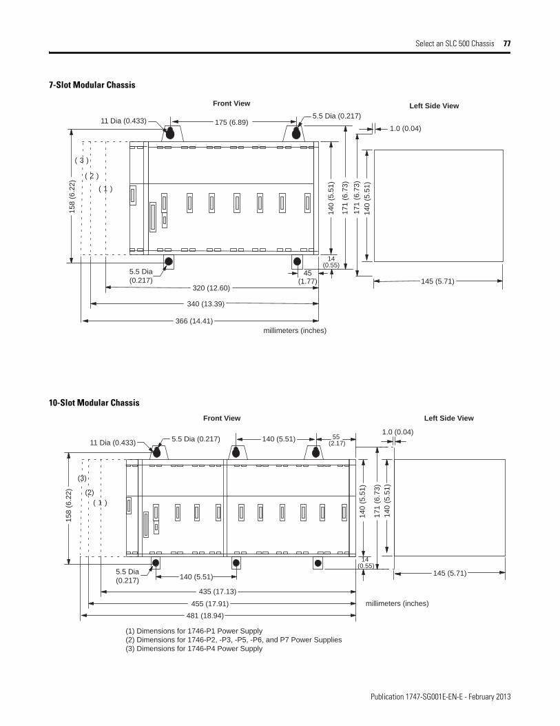
Publication 1747-SG001E-EN-E - February 2013
Select an SLC 500 Chassis 77
7-Slot Modular Chassis
10-Slot Modular Chassis
366 (14.41)
340 (13.39)
320 (12.60)145 (5.71)
175 (6.89)
14
0 (
5.5
1)
17
1 (
6.7
3)
14
0 (
5.5
1)
17
1 (
6.7
3)
15
8 (
6.2
2)
5.5 Dia
(0.217)45
(1.77)
14(0.55)
11 Dia (0.433)5.5 Dia (0.217)
1.0 (0.04)
Front View Left Side View
millimeters (inches)
( 3 )
( 2 )
( 1 )
481 (18.94)
455 (17.91)
435 (17.13)
17
1 (
6.7
3)
140 (5.51)145 (5.71)
140 (5.51)
14
0 (
5.5
1)
14
0 (
5.5
1)
15
8 (
6.2
2)
1.0 (0.04)55
(2.17)
5.5 Dia
(0.217)
11 Dia (0.433)
14 (0.55)
5.5 Dia (0.217)
(1) Dimensions for 1746-P1 Power Supply
(2) Dimensions for 1746-P2, -P3, -P5, -P6, and P7 Power Supplies
(3) Dimensions for 1746-P4 Power Supply
Front View Left Side View
millimeters (inches)
( 1 )
(2)
(3)
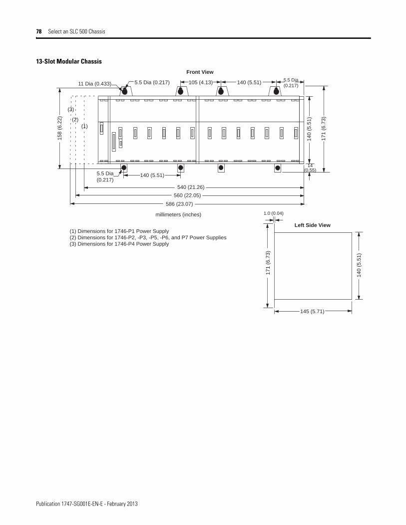
Publication 1747-SG001E-EN-E - February 2013
78 Select an SLC 500 Chassis
13-Slot Modular Chassis
586 (23.07)
540 (21.26)
560 (22.05)
17
1 (
6.7
3)
14
0 (
5.5
1)
15
8 (
6.2
2)
140 (5.51)
105 (4.13) 140 (5.51)5.5 Dia (0.217)11 Dia (0.433)
5.5 Dia
(0.217)
5.5 Dia
(0.217)
14(0.55)
(1)
(2)
(3)
145 (5.71)
17
1 (
6.7
3)
14
0 (
5.5
1)
1.0 (0.04)
Left Side View
Front View
millimeters (inches)
(1) Dimensions for 1746-P1 Power Supply
(2) Dimensions for 1746-P2, -P3, -P5, -P6, and P7 Power Supplies
(3) Dimensions for 1746-P4 Power Supply
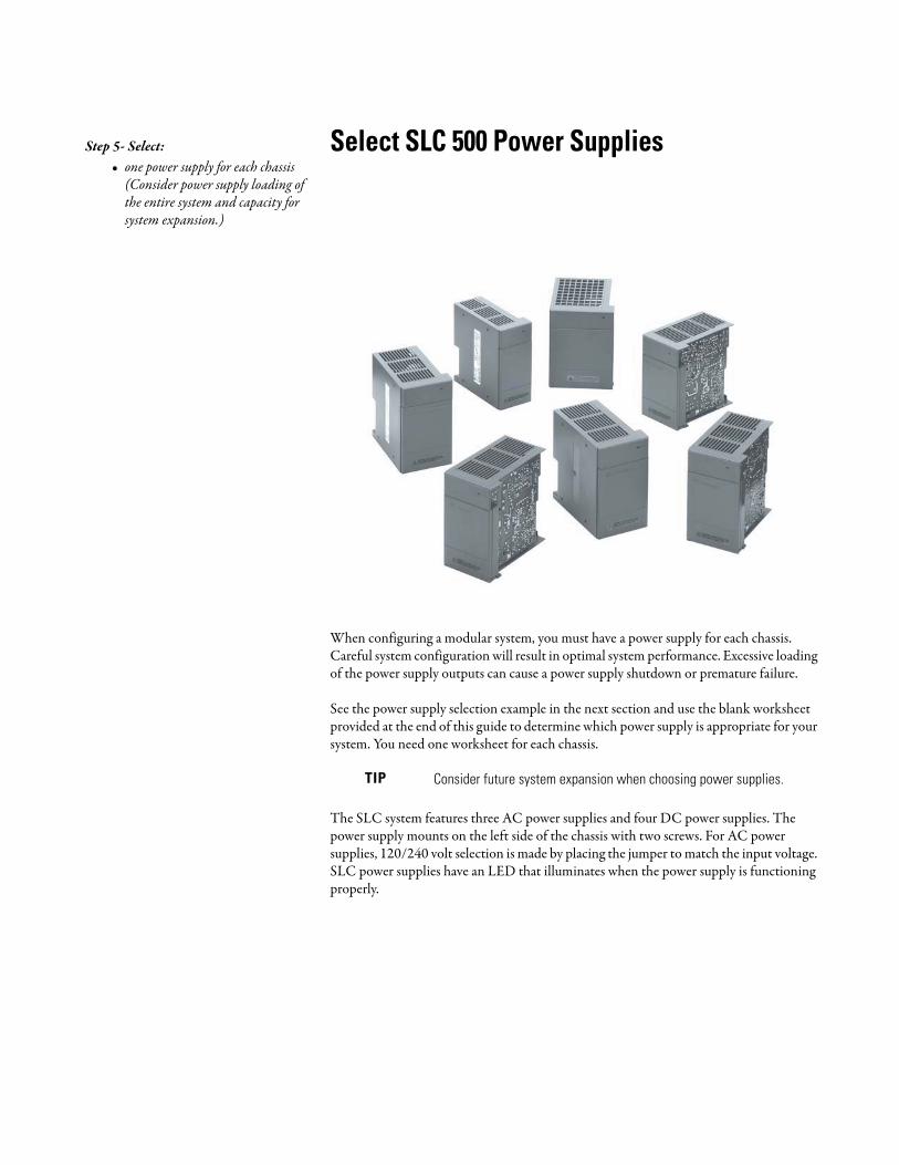
Select SLC 500 Power Supplies
When configuring a modular system, you must have a power supply for each chassis. Careful system configuration will result in optimal system performance. Excessive loading of the power supply outputs can cause a power supply shutdown or premature failure.
See the power supply selection example in the next section and use the blank worksheet provided at the end of this guide to determine which power supply is appropriate for your system. You need one worksheet for each chassis.
The SLC system features three AC power supplies and four DC power supplies. The power supply mounts on the left side of the chassis with two screws. For AC power supplies, 120/240 volt selection is made by placing the jumper to match the input voltage. SLC power supplies have an LED that illuminates when the power supply is functioning properly.
TIP Consider future system expansion when choosing power supplies.
Step 5- Select:• one power supply for each chassis
(Consider power supply loading of the entire system and capacity for system expansion.)
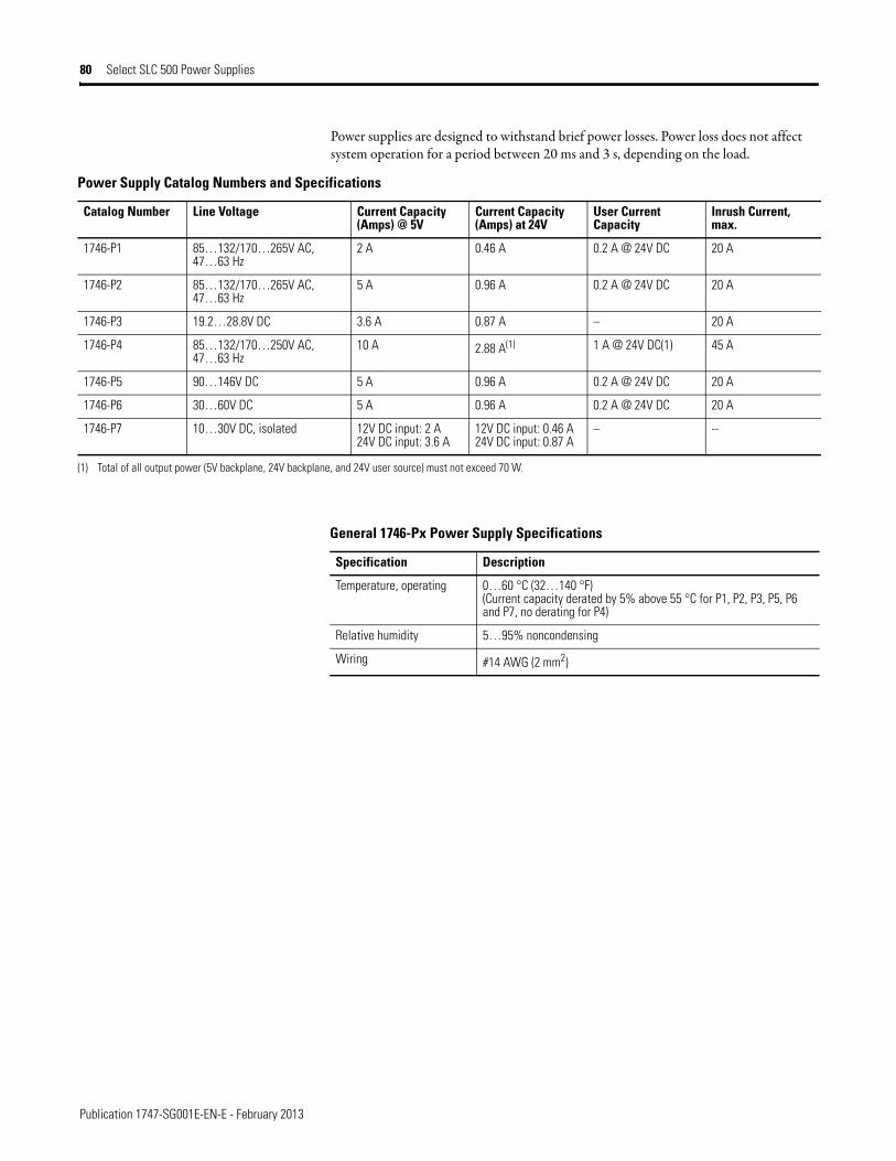
Publication 1747-SG001E-EN-E - February 2013
80 Select SLC 500 Power Supplies
Power supplies are designed to withstand brief power losses. Power loss does not affect system operation for a period between 20 ms and 3 s, depending on the load.
Power Supply Catalog Numbers and Specifications
Catalog Number Line Voltage Current Capacity (Amps) @ 5V
Current Capacity (Amps) at 24V
User Current Capacity
Inrush Current, max.
1746-P1 85…132/170…265V AC, 47…63 Hz
2 A 0.46 A 0.2 A @ 24V DC 20 A
1746-P2 85…132/170…265V AC, 47…63 Hz
5 A 0.96 A 0.2 A @ 24V DC 20 A
1746-P3 19.2…28.8V DC 3.6 A 0.87 A – 20 A
1746-P4 85…132/170…250V AC, 47…63 Hz
10 A 2.88 A(1) 1 A @ 24V DC(1) 45 A
1746-P5 90…146V DC 5 A 0.96 A 0.2 A @ 24V DC 20 A
1746-P6 30…60V DC 5 A 0.96 A 0.2 A @ 24V DC 20 A
1746-P7 10…30V DC, isolated 12V DC input: 2 A24V DC input: 3.6 A
12V DC input: 0.46 A24V DC input: 0.87 A
– --
(1) Total of all output power (5V backplane, 24V backplane, and 24V user source) must not exceed 70 W.
General 1746-Px Power Supply Specifications
Specification Description
Temperature, operating 0…60 °C (32…140 °F)(Current capacity derated by 5% above 55 °C for P1, P2, P3, P5, P6 and P7, no derating for P4)
Relative humidity 5…95% noncondensing
Wiring #14 AWG (2 mm2)
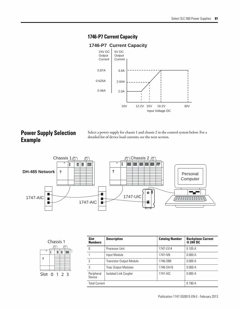
Publication 1747-SG001E-EN-E - February 2013
Select SLC 500 Power Supplies 81
1746-P7 Current Capacity
Power Supply Selection Example
Select a power supply for chassis 1 and chassis 2 in the control system below. For a detailed list of device load currents, see the next section.
3.6A
2.64A
2.0A
0.87A
0.625A
0.46A
10V 12.2V 15V 19.2V 30V
1746-P7 Current Capacity 24V DC
Output
Current
5V DC
Output
Current
Input Voltage DC
? ?
1747-AIC 1747-AIC
1747-UIC
2 sissahC 1 sissahC
Personal
Computer
DH-485 Network
Slot Numbers
Description Catalog Number Backplane Current @ 24V DC
0 Processor Unit 1747-L514 0.105 A
1 Input Module 1747-IV8 0.000 A
2 Transistor Output Module 1746-OB8 0.000 A
3 Triac Output Modules 1746-OA16 0.000 A
Peripheral Device
Isolated Link Coupler 1747-AIC 0.085 A
Total Current 0.190 A
?
Chassis 1
Slot 0 1 2 3
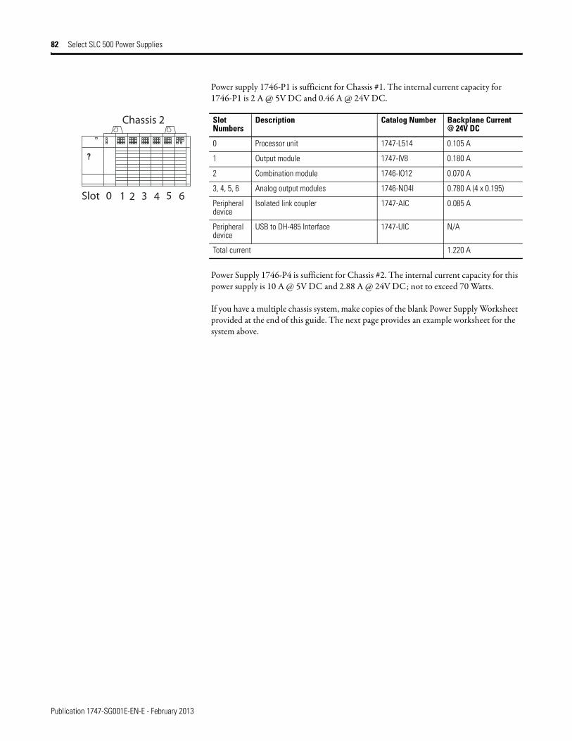
Publication 1747-SG001E-EN-E - February 2013
82 Select SLC 500 Power Supplies
Power supply 1746-P1 is sufficient for Chassis #1. The internal current capacity for 1746-P1 is 2 A @ 5V DC and 0.46 A @ 24V DC.
Power Supply 1746-P4 is sufficient for Chassis #2. The internal current capacity for this power supply is 10 A @ 5V DC and 2.88 A @ 24V DC; not to exceed 70 Watts.
If you have a multiple chassis system, make copies of the blank Power Supply Worksheet provided at the end of this guide. The next page provides an example worksheet for the system above.
Slot Numbers
Description Catalog Number Backplane Current @ 24V DC
0 Processor unit 1747-L514 0.105 A
1 Output module 1747-IV8 0.180 A
2 Combination module 1746-IO12 0.070 A
3, 4, 5, 6 Analog output modules 1746-NO4I 0.780 A (4 x 0.195)
Peripheral device
Isolated link coupler 1747-AIC 0.085 A
Peripheraldevice
USB to DH-485 Interface 1747-UIC N/A
Total current 1.220 A
?
Slot
Chassis 2
0 1 32 4 5 6
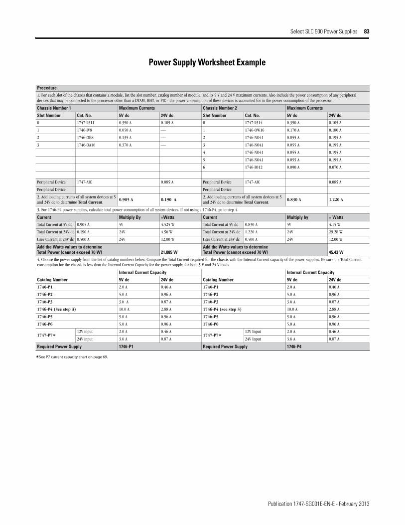
Publication 1747-SG001E-EN-E - February 2013
Select SLC 500 Power Supplies 83
Power Supply Worksheet Example
Procedure
1. For each slot of the chassis that contains a module, list the slot number, catalog number of module, and its 5 V and 24 V maximum currents. Also include the power consumption of any peripheraldevices that may be connected to the processor other than a DTAM, HHT, or PIC - the power consumption of these devices is accounted for in the power consumption of the processor.
stnerruC mumixaM2 rebmuN sissahCstnerruC mumixaM1 rebmuN sissahC
Slot Number Cat. No. 5V dc 24V dc Slot Number Cat. No. 5V dc 24V dc
0 1747-L511 0.350 A 0.105 A 0 1747-L514 0.350 A 0.105 A
1 1746-IV8 0.050 A ⎯ 1 1746-OW16 0.170 A 0.180 A
2 1746-OB8 0.135 A ⎯ 2 1746-NO41 0.055 A 0.195 A
3 1746-OA16 0.370 A ⎯ 3 1746-NO41 0.055 A 0.195 A
4 1746-NO41 0.055 A 0.195 A
5 1746-NO41 0.055 A 0.195 A
6 1746-IO12 0.090 A 0.070 A
A 580.0CIA-7471eciveD larehpirePA 580.0CIA-7471eciveD larehpireP
eciveD larehpirePeciveD larehpireP
2. Add loading currents of all system devices at 5and 24V dc to determine Total Current.
0.905 A 0.190 A2. Add loading currents of all system devices at 5and 24V dc to determine Total Current.
0.830 A 1.220 A
3. For 1746-P4 power supplies, calculate total power consumption of all system devices. If not using a 1746-P4, go to step 4.
Current Multiply By =Watts Current Multiply by = Watts
Total Current at 5V dc 0.905 A 5V 4.525 W Total Current at 5V dc 0.830 A 5V 4.15 W
Total Current at 24V dc 0.190 A 24V 4.56 W Total Current at 24V dc 1.220 A 24V 29.28 W
User Current at 24V dc 0.500 A 24V 12.00 W User Current at 24V dc 0.500 A 24V 12.00 W
Add the Watts values to determine Total Power (cannot exceed 70 W) 21.085 W
Add the Watts values to determine Total Power (cannot exceed 70 W) 45.43 W
4. Choose the power supply from the list of catalog numbers below. Compare the Total Current required for the chassis with the Internal Current capacity of the power supplies. Be sure the Total Currentconsumption for the chassis is less than the Internal Current Capacity for the power supply, for both 5 V and 24 V loads.
Catalog Number
Internal Current Capacity
Catalog Number
Internal Current Capacity
5V dc 24V dc 5V dc 24V dc
1746-P1 2.0 A 0.46 A 1746-P1 2.0 A 0.46 A
1746-P2 5.0 A 0.96 A 1746-P2 5.0 A 0.96 A
1746-P3 3.6 A 0.87 A 1746-P3 3.6 A 0.87 A
1746-P4 (See step 3) 10.0 A 2.88 A 1746-P4 (see step 3) 10.0 A 2.88 A
1746-P5 5.0 A 0.96 A 1746-P5 5.0 A 0.96 A
1746-P6 5.0 A 0.96 A 1746-P6 5.0 A 0.96 A
1747-P712V input 2.0 A 0.46 A
1747-P712V Input 2.0 A 0.46 A
24V input 3.6 A 0.87 A 24V Input 3.6 A 0.87 A
Required Power Supply 1746-P1 Required Power Supply 1746-P4
See P7 current capacity chart on page 69.
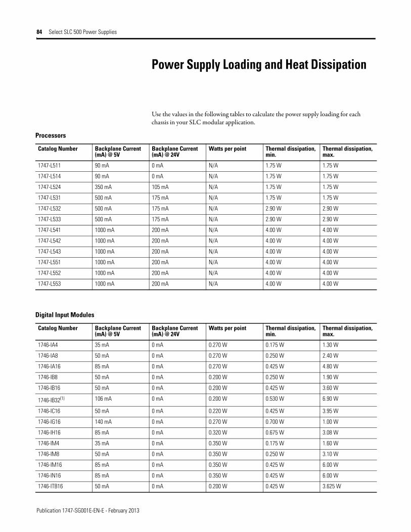
Publication 1747-SG001E-EN-E - February 2013
84 Select SLC 500 Power Supplies
Power Supply Loading and Heat Dissipation
Use the values in the following tables to calculate the power supply loading for each chassis in your SLC modular application.
Processors
Catalog Number Backplane Current (mA) @ 5V
Backplane Current (mA) @ 24V
Watts per point Thermal dissipation, min.
Thermal dissipation, max.
1747-L511 90 mA 0 mA N/A 1.75 W 1.75 W
1747-L514 90 mA 0 mA N/A 1.75 W 1.75 W
1747-L524 350 mA 105 mA N/A 1.75 W 1.75 W
1747-L531 500 mA 175 mA N/A 1.75 W 1.75 W
1747-L532 500 mA 175 mA N/A 2.90 W 2.90 W
1747-L533 500 mA 175 mA N/A 2.90 W 2.90 W
1747-L541 1000 mA 200 mA N/A 4.00 W 4.00 W
1747-L542 1000 mA 200 mA N/A 4.00 W 4.00 W
1747-L543 1000 mA 200 mA N/A 4.00 W 4.00 W
1747-L551 1000 mA 200 mA N/A 4.00 W 4.00 W
1747-L552 1000 mA 200 mA N/A 4.00 W 4.00 W
1747-L553 1000 mA 200 mA N/A 4.00 W 4.00 W
Digital Input Modules
Catalog Number Backplane Current (mA) @ 5V
Backplane Current (mA) @ 24V
Watts per point Thermal dissipation, min.
Thermal dissipation, max.
1746-IA4 35 mA 0 mA 0.270 W 0.175 W 1.30 W
1746-IA8 50 mA 0 mA 0.270 W 0.250 W 2.40 W
1746-IA16 85 mA 0 mA 0.270 W 0.425 W 4.80 W
1746-IB8 50 mA 0 mA 0.200 W 0.250 W 1.90 W
1746-IB16 50 mA 0 mA 0.200 W 0.425 W 3.60 W
1746-IB32(1) 106 mA 0 mA 0.200 W 0.530 W 6.90 W
1746-IC16 50 mA 0 mA 0.220 W 0.425 W 3.95 W
1746-IG16 140 mA 0 mA 0.270 W 0.700 W 1.00 W
1746-IH16 85 mA 0 mA 0.320 W 0.675 W 3.08 W
1746-IM4 35 mA 0 mA 0.350 W 0.175 W 1.60 W
1746-IM8 50 mA 0 mA 0.350 W 0.250 W 3.10 W
1746-IM16 85 mA 0 mA 0.350 W 0.425 W 6.00 W
1746-IN16 85 mA 0 mA 0.350 W 0.425 W 6.00 W
1746-ITB16 50 mA 0 mA 0.200 W 0.425 W 3.625 W
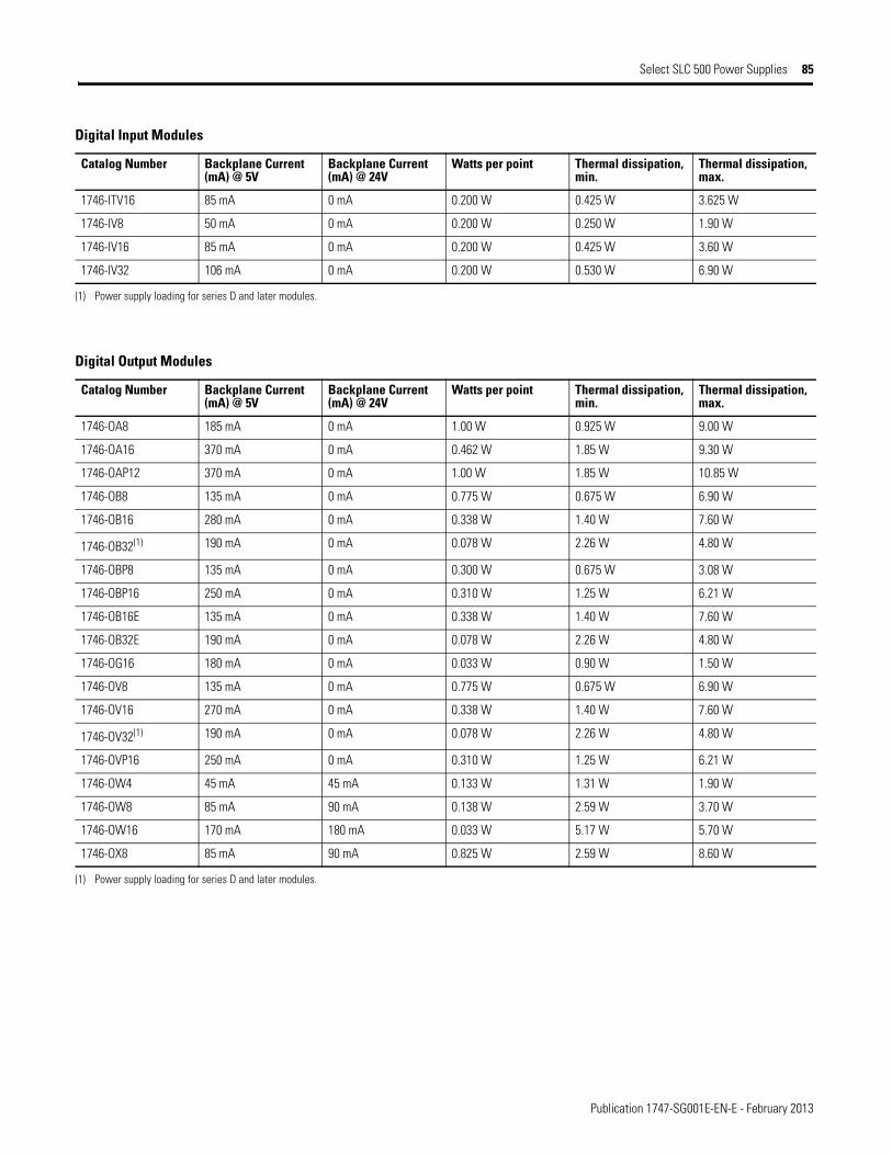
Publication 1747-SG001E-EN-E - February 2013
Select SLC 500 Power Supplies 85
1746-ITV16 85 mA 0 mA 0.200 W 0.425 W 3.625 W
1746-IV8 50 mA 0 mA 0.200 W 0.250 W 1.90 W
1746-IV16 85 mA 0 mA 0.200 W 0.425 W 3.60 W
1746-IV32 106 mA 0 mA 0.200 W 0.530 W 6.90 W
(1) Power supply loading for series D and later modules.
Digital Input Modules
Catalog Number Backplane Current (mA) @ 5V
Backplane Current (mA) @ 24V
Watts per point Thermal dissipation, min.
Thermal dissipation, max.
Digital Output Modules
Catalog Number Backplane Current (mA) @ 5V
Backplane Current (mA) @ 24V
Watts per point Thermal dissipation, min.
Thermal dissipation, max.
1746-OA8 185 mA 0 mA 1.00 W 0.925 W 9.00 W
1746-OA16 370 mA 0 mA 0.462 W 1.85 W 9.30 W
1746-OAP12 370 mA 0 mA 1.00 W 1.85 W 10.85 W
1746-OB8 135 mA 0 mA 0.775 W 0.675 W 6.90 W
1746-OB16 280 mA 0 mA 0.338 W 1.40 W 7.60 W
1746-OB32(1) 190 mA 0 mA 0.078 W 2.26 W 4.80 W
1746-OBP8 135 mA 0 mA 0.300 W 0.675 W 3.08 W
1746-OBP16 250 mA 0 mA 0.310 W 1.25 W 6.21 W
1746-OB16E 135 mA 0 mA 0.338 W 1.40 W 7.60 W
1746-OB32E 190 mA 0 mA 0.078 W 2.26 W 4.80 W
1746-OG16 180 mA 0 mA 0.033 W 0.90 W 1.50 W
1746-OV8 135 mA 0 mA 0.775 W 0.675 W 6.90 W
1746-OV16 270 mA 0 mA 0.338 W 1.40 W 7.60 W
1746-OV32(1) 190 mA 0 mA 0.078 W 2.26 W 4.80 W
1746-OVP16 250 mA 0 mA 0.310 W 1.25 W 6.21 W
1746-OW4 45 mA 45 mA 0.133 W 1.31 W 1.90 W
1746-OW8 85 mA 90 mA 0.138 W 2.59 W 3.70 W
1746-OW16 170 mA 180 mA 0.033 W 5.17 W 5.70 W
1746-OX8 85 mA 90 mA 0.825 W 2.59 W 8.60 W
(1) Power supply loading for series D and later modules.
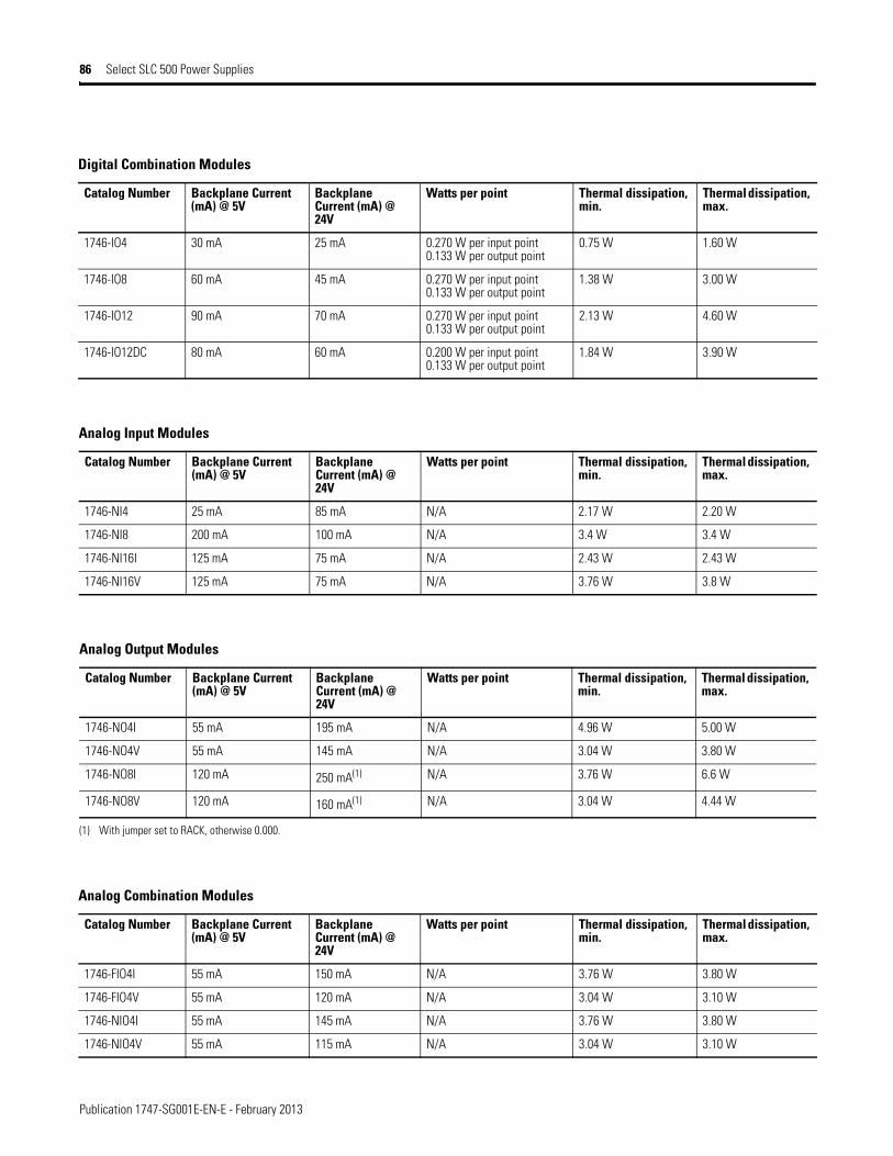
Publication 1747-SG001E-EN-E - February 2013
86 Select SLC 500 Power Supplies
Digital Combination Modules
Catalog Number Backplane Current (mA) @ 5V
Backplane Current (mA) @ 24V
Watts per point Thermal dissipation, min.
Thermal dissipation, max.
1746-IO4 30 mA 25 mA 0.270 W per input point0.133 W per output point
0.75 W 1.60 W
1746-IO8 60 mA 45 mA 0.270 W per input point0.133 W per output point
1.38 W 3.00 W
1746-IO12 90 mA 70 mA 0.270 W per input point0.133 W per output point
2.13 W 4.60 W
1746-IO12DC 80 mA 60 mA 0.200 W per input point0.133 W per output point
1.84 W 3.90 W
Analog Input Modules
Catalog Number Backplane Current (mA) @ 5V
Backplane Current (mA) @ 24V
Watts per point Thermal dissipation, min.
Thermal dissipation, max.
1746-NI4 25 mA 85 mA N/A 2.17 W 2.20 W
1746-NI8 200 mA 100 mA N/A 3.4 W 3.4 W
1746-NI16I 125 mA 75 mA N/A 2.43 W 2.43 W
1746-NI16V 125 mA 75 mA N/A 3.76 W 3.8 W
Analog Output Modules
Catalog Number Backplane Current (mA) @ 5V
Backplane Current (mA) @ 24V
Watts per point Thermal dissipation, min.
Thermal dissipation, max.
1746-NO4I 55 mA 195 mA N/A 4.96 W 5.00 W
1746-NO4V 55 mA 145 mA N/A 3.04 W 3.80 W
1746-NO8I 120 mA 250 mA(1) N/A 3.76 W 6.6 W
1746-NO8V 120 mA 160 mA(1) N/A 3.04 W 4.44 W
(1) With jumper set to RACK, otherwise 0.000.
Analog Combination Modules
Catalog Number Backplane Current (mA) @ 5V
Backplane Current (mA) @ 24V
Watts per point Thermal dissipation, min.
Thermal dissipation, max.
1746-FIO4I 55 mA 150 mA N/A 3.76 W 3.80 W
1746-FIO4V 55 mA 120 mA N/A 3.04 W 3.10 W
1746-NIO4I 55 mA 145 mA N/A 3.76 W 3.80 W
1746-NIO4V 55 mA 115 mA N/A 3.04 W 3.10 W
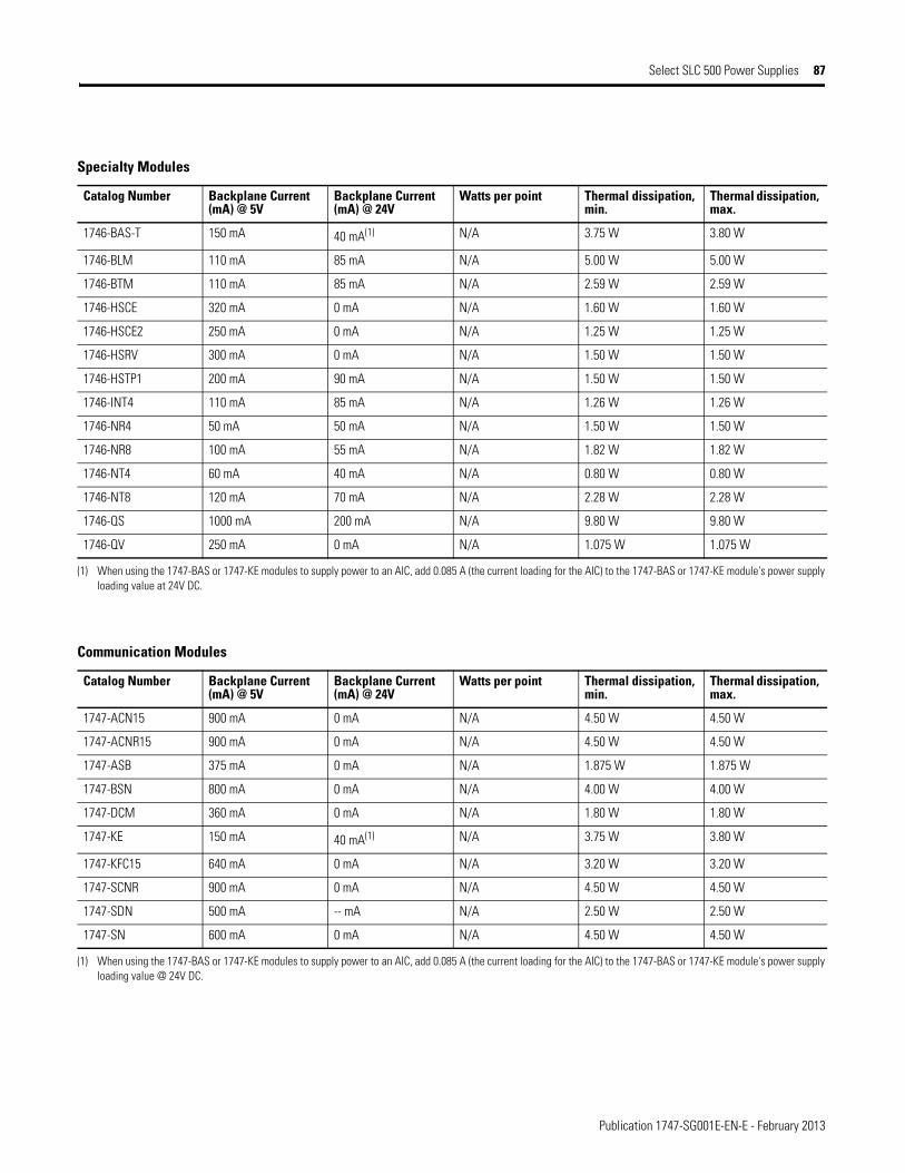
Publication 1747-SG001E-EN-E - February 2013
Select SLC 500 Power Supplies 87
Specialty Modules
Catalog Number Backplane Current (mA) @ 5V
Backplane Current (mA) @ 24V
Watts per point Thermal dissipation, min.
Thermal dissipation, max.
1746-BAS-T 150 mA 40 mA(1) N/A 3.75 W 3.80 W
1746-BLM 110 mA 85 mA N/A 5.00 W 5.00 W
1746-BTM 110 mA 85 mA N/A 2.59 W 2.59 W
1746-HSCE 320 mA 0 mA N/A 1.60 W 1.60 W
1746-HSCE2 250 mA 0 mA N/A 1.25 W 1.25 W
1746-HSRV 300 mA 0 mA N/A 1.50 W 1.50 W
1746-HSTP1 200 mA 90 mA N/A 1.50 W 1.50 W
1746-INT4 110 mA 85 mA N/A 1.26 W 1.26 W
1746-NR4 50 mA 50 mA N/A 1.50 W 1.50 W
1746-NR8 100 mA 55 mA N/A 1.82 W 1.82 W
1746-NT4 60 mA 40 mA N/A 0.80 W 0.80 W
1746-NT8 120 mA 70 mA N/A 2.28 W 2.28 W
1746-QS 1000 mA 200 mA N/A 9.80 W 9.80 W
1746-QV 250 mA 0 mA N/A 1.075 W 1.075 W
(1) When using the 1747-BAS or 1747-KE modules to supply power to an AIC, add 0.085 A (the current loading for the AIC) to the 1747-BAS or 1747-KE module's power supply loading value at 24V DC.
Communication Modules
Catalog Number Backplane Current (mA) @ 5V
Backplane Current (mA) @ 24V
Watts per point Thermal dissipation, min.
Thermal dissipation, max.
1747-ACN15 900 mA 0 mA N/A 4.50 W 4.50 W
1747-ACNR15 900 mA 0 mA N/A 4.50 W 4.50 W
1747-ASB 375 mA 0 mA N/A 1.875 W 1.875 W
1747-BSN 800 mA 0 mA N/A 4.00 W 4.00 W
1747-DCM 360 mA 0 mA N/A 1.80 W 1.80 W
1747-KE 150 mA 40 mA(1) N/A 3.75 W 3.80 W
1747-KFC15 640 mA 0 mA N/A 3.20 W 3.20 W
1747-SCNR 900 mA 0 mA N/A 4.50 W 4.50 W
1747-SDN 500 mA -- mA N/A 2.50 W 2.50 W
1747-SN 600 mA 0 mA N/A 4.50 W 4.50 W
(1) When using the 1747-BAS or 1747-KE modules to supply power to an AIC, add 0.085 A (the current loading for the AIC) to the 1747-BAS or 1747-KE module's power supply loading value @ 24V DC.

Publication 1747-SG001E-EN-E - February 2013
88 Select SLC 500 Power Supplies
Peripheral Devices
Catalog Number Backplane Current (mA) @ 5V
Backplane Current (mA) @ 24V
Watts per point Thermal dissipation, min.
Thermal dissipation, max.
1747-AIC 0 mA 85 mA N/A 2.00 W 2.00 W
1747-UIC(1) N/A N/A N/A N/A N/A
1747-PSD N/A N/A N/A N/A N/A
1761-NET-AIC(2) 0 mA 0 mA N/A 2.50 W 2.50 W
1761-NET-DNI 0 mA 0 mA N/A 2.50 W 2.50 W
1761-NET-ENIW 0 mA 0 mA N/A 2.50 W 2.00 W
(1) 1747-UIC power consumption is less than 100 mA.
(2) Current for the 1761-NET-AIC and 1761-NET-ENI(W) must be supplied from an external 24V DC source.
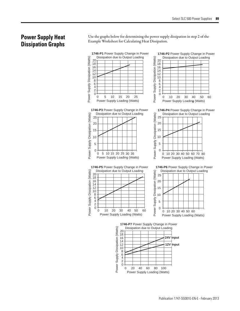
Publication 1747-SG001E-EN-E - February 2013
Select SLC 500 Power Supplies 89
Power Supply Heat Dissipation Graphs
Use the graphs below for determining the power supply dissipation in step 2 of the Example Worksheet for Calculating Heat Dissipation.
02468
101214161820
0 5 10 15 20 25
Power Supply Loading (Watts)
1746-P1 Power Supply Change in Power
Dissipation due to Output Loading
Po
we
r S
up
ply
Dis
sip
atio
n (
Wa
tts)
1746-P2 Power Supply Change in Power
Dissipation due to Output Loading
0 10 20 30 40 50
Power Supply Loading (Watts)
02468
101214161820
Po
we
r S
up
ply
Dis
sip
atio
n (
Wa
tts)
1746-P3 Power Supply Change in Power
Dissipation due to Output Loading
Po
we
r S
up
ply
Dis
sip
atio
n (
Wa
tts)
00 5 10 15 20 25
Power Supply Loading (Watts)
30 35
5
10
15
20
25
1746-P4 Power Supply Change in Power
Dissipation due to Output Loading
0 10 20 30 40 50
Power Supply Loading (Watts)
60 70 800
5
10
15
20
25
Po
we
r S
up
ply
Dis
sip
atio
n (
Wa
tts)
1746-P5 Power Supply Change in Power
Dissipation due to Output Loading
02468
101214161820
Po
we
r S
up
ply
Dis
sip
atio
n (
Wa
tts)
0
5
10
15
20
25
Po
we
r S
up
ply
Dis
sip
atio
n (
Wa
tts)
0 10 20 30 40 50
Power Supply Loading (Watts)
60
1746-P6 Power Supply Change in Power
Dissipation due to Output Loading
02468
101214161820
Po
we
r S
up
ply
Dis
sip
atio
n (
Wa
tts)
1746-P7 Power Supply Change in Power
Dissipation due to Output Loading
0 20 40 60 80 100
Power Supply Loading (Watts)
0 10 20 30 40 50
Power Supply Loading (Watts)
60
24V Input
12V Input
60
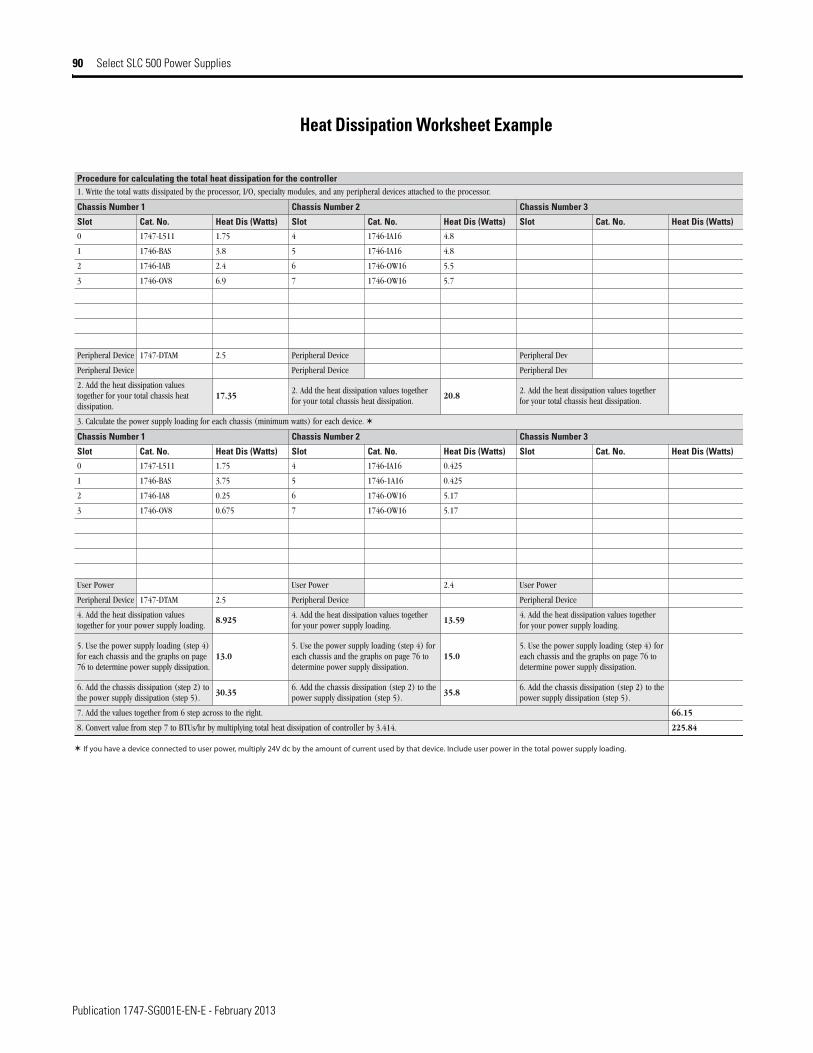
Publication 1747-SG001E-EN-E - February 2013
90 Select SLC 500 Power Supplies
Heat Dissipation Worksheet Example
Procedure for calculating the total heat dissipation for the controller 1. Write the total watts dissipated by the processor, I/O, specialty modules, and any peripheral devices attached to the processor.
3 rebmuN sissahC2 rebmuN sissahC1 rebmuN sissahC
Slot Cat. No. Heat Dis (Watts) Slot Cat. No. Heat Dis (Watts) Slot Cat. No. Heat Dis (Watts)
0 1747-L511 1.75 4 1746-IA16 4.8
1 1746-BAS 3.8 5 1746-IA16 4.8
2 1746-IAB 2.4 6 1746-OW16 5.5
3 1746-OV8 6.9 7 1746-OW16 5.7
veD larehpirePeciveD larehpireP5.2MATD-7471eciveD larehpireP
veD larehpirePeciveD larehpirePeciveD larehpireP
2. Add the heat dissipation valuestogether for your total chassis heatdissipation.
17.352. Add the heat dissipation values togetherfor your total chassis heat dissipation.
20.82. Add the heat dissipation values togetherfor your total chassis heat dissipation.
3. Calculate the power supply loading for each chassis (minimum watts) for each device.
3 rebmuN sissahC2 rebmuN sissahC1 rebmuN sissahC
Slot Cat. No. Heat Dis (Watts) Slot Cat. No. Heat Dis (Watts) Slot Cat. No. Heat Dis (Watts)
0 1747-L511 1.75 4 1746-IA16 0.425
1 1746-BAS 3.75 5 1746-1A16 0.425
2 1746-IA8 0.25 6 1746-OW16 5.17
3 1746-OV8 0.675 7 1746-OW16 5.17
rewoP resU4.2rewoP resUrewoP resU
eciveD larehpirePeciveD larehpireP5.2MATD-7471eciveD larehpireP
4. Add the heat dissipation valuestogether for your power supply loading.
8.9254. Add the heat dissipation values togetherfor your power supply loading.
13.594. Add the heat dissipation values togetherfor your power supply loading.
5. Use the power supply loading (step 4)for each chassis and the graphs on page76 to determine power supply dissipation.
13.05. Use the power supply loading (step 4) foreach chassis and the graphs on page 76 todetermine power supply dissipation.
15.05. Use the power supply loading (step 4) foreach chassis and the graphs on page 76 todetermine power supply dissipation.
6. Add the chassis dissipation (step 2) tothe power supply dissipation (step 5).
30.356. Add the chassis dissipation (step 2) to thepower supply dissipation (step 5).
35.86. Add the chassis dissipation (step 2) to thepower supply dissipation (step 5).
7. Add the values together from 6 step across to the right. 66.15
8. Convert value from step 7 to BTUs/hr by multiplying total heat dissipation of controller by 3.414. 225.84
If you have a device connected to user power, multiply 24V dc by the amount of current used by that device. Include user power in the total power supply loading.
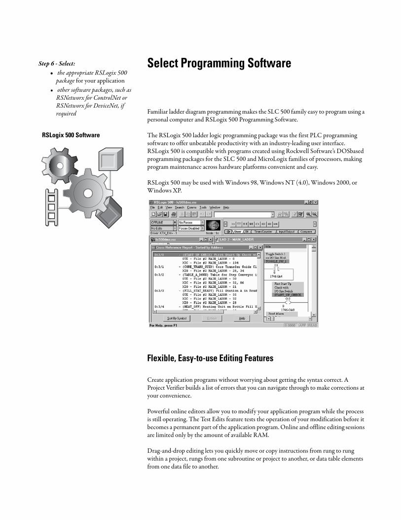
Select Programming Software
Familiar ladder diagram programming makes the SLC 500 family easy to program using a personal computer and RSLogix 500 Programming Software.
The RSLogix 500 ladder logic programming package was the first PLC programming software to offer unbeatable productivity with an industry-leading user interface. RSLogix 500 is compatible with programs created using Rockwell Software’s DOSbased programming packages for the SLC 500 and MicroLogix families of processors, making program maintenance across hardware platforms convenient and easy.
RSLogix 500 may be used with Windows 98, Windows NT (4.0), Windows 2000, or Windows XP.
Flexible, Easy-to-use Editing Features
Create application programs without worrying about getting the syntax correct. A Project Verifier builds a list of errors that you can navigate through to make corrections at your convenience.
Powerful online editors allow you to modify your application program while the process is still operating. The Test Edits feature tests the operation of your modification before it becomes a permanent part of the application program. Online and offline editing sessions are limited only by the amount of available RAM.
Drag-and-drop editing lets you quickly move or copy instructions from rung to rung within a project, rungs from one subroutine or project to another, or data table elements from one data file to another.
Step 6 - Select: • the appropriate RSLogix 500
package for your application• other software packages, such as
RSNetworx for ControlNet or RSNetworx for DeviceNet, if required
RSLogix 500 Software
Publication 1747-SG001E-EN-E - February 2013
92 Select Programming Software
Context menus for common software tools are quickly accessible by clicking the right mouse button on addresses, symbols, instructions, rungs, or other application objects. This convenience provides you with all the necessary functionality to accomplish a task within a single menu. This is a time-saving feature because you don’t have to remember the placement of functionality options in the menu bar.
Point-and-Click I/O Configuration
The easy-to-use I/O Configurator lets you click or drag-and-drop a module from an all-inclusive list to assign it to a slot in your configuration. Advanced configuration, required for specialty and analog modules, is easily accessible. Convenient forms speed entry of configuration data. An I/O auto configuration feature is also available.
Powerful Database Editor
Use the Symbol Group Editor to build and classify groups of symbols so that you can easily select portions of your recorded documentation for use across multiple projects. The Symbol Picker list allows you to assign addresses or symbols to your ladder logic instructions simply by clicking on them.
Export your database to Comma-Separated-Value (CSV) format to use or manipulate the data in your favorite spreadsheet program. When finished, simply import the CSV file into RSLogix 500.
Diagnostics and Troubleshooting Tools
Quickly locate the specific area in the application that is causing a problem with Advanced Diagnostics. Diagnose the interaction of output instructions within a section of your program by viewing them at the same time.
Simultaneously examine the status of bits, timers, counters, inputs and outputs all in one window with the Custom Data Monitor. Each application project you create can have its own Custom Data Monitor window.
Use the tabbed Status displays to easily review status bit settings specific to your application programming, including Scan Time and Math Register information, Interrupt settings, and more.
Assistance on Demand
Comprehensive online help provides an instruction reference as well as step by step instructions for common tasks.

Publication 1747-SG001E-EN-E - February 2013
Select Programming Software 93
RSLogix 500 Programming Packages
All of the packages described in the table below are English versions on CD-ROM. They can be used with Windows 98, Windows 2000, Windows ME, Windows XP, or Windows NT (4.0) only.
The table below indicates with an "", which cables are compatible with the SLC 5/01 through 5/05 processors.
RSLogix 500 Software
Description
RSLogix 500 Programming for the SLC 500
and MicroLogix Families
9324-RL0300ENE Create, modify, and monitor application
programs used by both the SLC 500 and
MicroLogix Programmable Controller families.
RSLogix 500 Starter 9324-RL0100ENE An effective solution for cost-consious or entrylevel
users, this package provides the basic
functionality of the full-featured version with
some of the advanced features disabled.
RSLogix 500 Professional 9324-RL0700NXENE This package combines the features of the
RSLogix 500 Standard plus Microsoft VBA
scripting capability, and includes RSLogix
Emulate 500, RSNetworx for ControlNet
RSNetworx for EtherNet/IP and RSNetworx for
DeviceNet.
IMPORTANT You must provide a means of communication between the PC and the processor.
Processor SLC 5/01 SLC 5/02 SLC 5/03 SLC 5/04 SLC 5/05
1747-UIC ✓ ✓ ✓
requires 1747-C13 requires 1747-C13requires 1747-CP3
requires 1747-CP3
1747-CP3 ✓ ✓ ✓
1747-KTX, -PKTX ✓ ✓
requires 1784-CP14 requires 1784-CP13
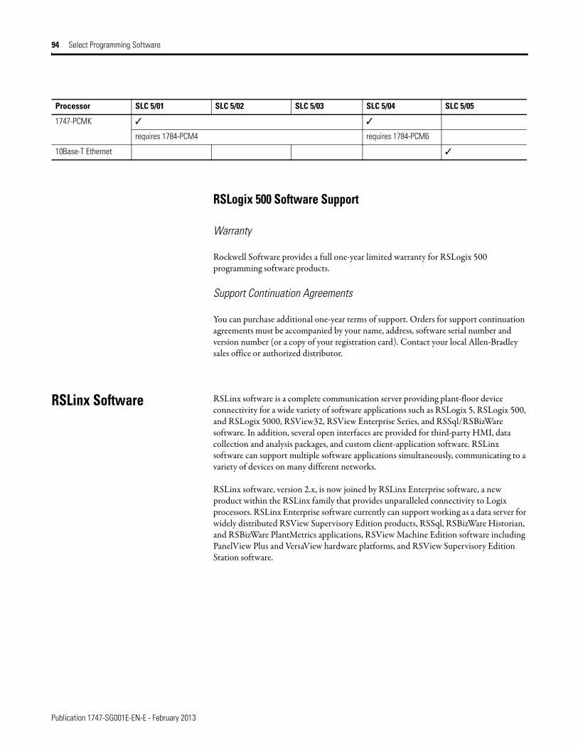
Publication 1747-SG001E-EN-E - February 2013
94 Select Programming Software
RSLogix 500 Software Support
Warranty
Rockwell Software provides a full one-year limited warranty for RSLogix 500 programming software products.
Support Continuation Agreements
You can purchase additional one-year terms of support. Orders for support continuation agreements must be accompanied by your name, address, software serial number and version number (or a copy of your registration card). Contact your local Allen-Bradley sales office or authorized distributor.
RSLinx Software RSLinx software is a complete communication server providing plant-floor device connectivity for a wide variety of software applications such as RSLogix 5, RSLogix 500, and RSLogix 5000, RSView32, RSView Enterprise Series, and RSSql/RSBizWare software. In addition, several open interfaces are provided for third-party HMI, data collection and analysis packages, and custom client-application software. RSLinx software can support multiple software applications simultaneously, communicating to a variety of devices on many different networks.
RSLinx software, version 2.x, is now joined by RSLinx Enterprise software, a new product within the RSLinx family that provides unparalleled connectivity to Logix processors. RSLinx Enterprise software currently can support working as a data server for widely distributed RSView Supervisory Edition products, RSSql, RSBizWare Historian, and RSBizWare PlantMetrics applications, RSView Machine Edition software including PanelView Plus and VersaView hardware platforms, and RSView Supervisory Edition Station software.
1747-PCMK ✓ ✓
requires 1784-PCM4 requires 1784-PCM6
10Base-T Ethernet ✓
Processor SLC 5/01 SLC 5/02 SLC 5/03 SLC 5/04 SLC 5/05
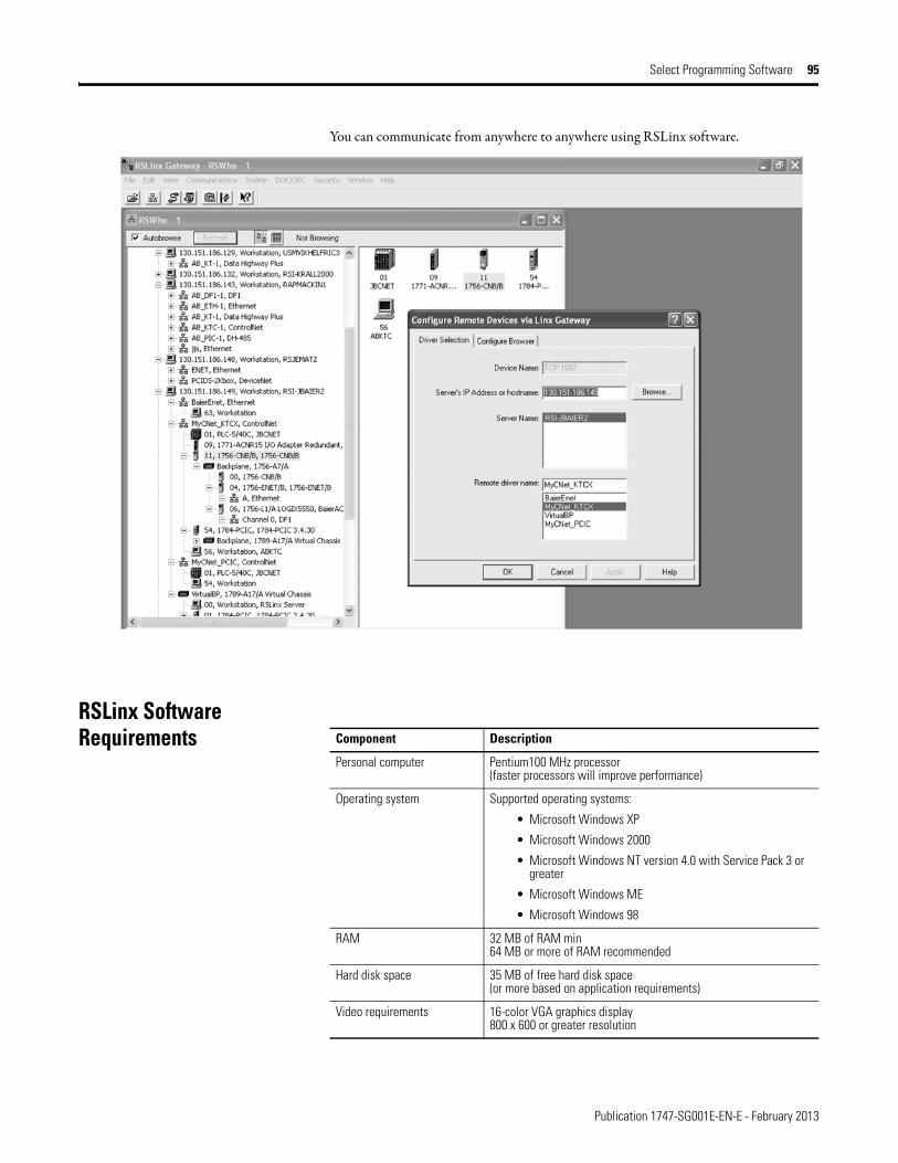
Publication 1747-SG001E-EN-E - February 2013
Select Programming Software 95
You can communicate from anywhere to anywhere using RSLinx software.
RSLinx Software Requirements
Component Description
Personal computer Pentium100 MHz processor(faster processors will improve performance)
Operating system Supported operating systems:
• Microsoft Windows XP
• Microsoft Windows 2000
• Microsoft Windows NT version 4.0 with Service Pack 3 or greater
• Microsoft Windows ME
• Microsoft Windows 98
RAM 32 MB of RAM min64 MB or more of RAM recommended
Hard disk space 35 MB of free hard disk space(or more based on application requirements)
Video requirements 16-color VGA graphics display800 x 600 or greater resolution
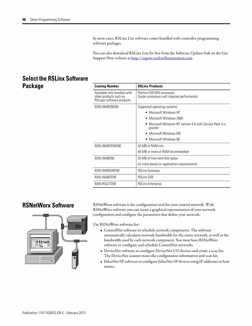
Publication 1747-SG001E-EN-E - February 2013
96 Select Programming Software
In most cases, RSLinx Lite software comes bundled with controller programming software packages.
You can also download RSLinx Lite for free from the Software Updates link on the Get Support Now website at http://suport.rockwellautomation.com.
Select the RSLinx Software Package
RSNetWorx Software RSNetWorx software is the configuration tool for your control network. With RSNetWorx software you can create a graphical representation of your network configuration and configure the parameters that define your network.
Use RSNetWorx software for:• ControlNet software to schedule network components. The software
automatically calculates network bandwidth for the entire network, as well as the bandwidth used by each network component. You must have RSNetWorx software to configure and schedule ControlNet networks.
• DeviceNet software to configure DeviceNet I/O devices and create a scan list. The DeviceNet scanner stores the configuration information and scan list.
• EtherNet/IP software to configure EtherNet/IP devices using IP addresses or host names.
Catalog Number RSLinx Products
Available only bundled with other products such as RSLogix software products.
Pentium100 MHz processor(faster processors will improve performance)
9355-WABSNENE Supported operating systems:
• Microsoft Windows XP
• Microsoft Windows 2000
• Microsoft Windows NT version 4.0 with Service Pack 3 or greater
• Microsoft Windows ME
• Microsoft Windows 98
9355-WABOEMENE 32 MB of RAM min
64 MB or more of RAM recommended
9355-WABENE 35 MB of free hard disk space
(or more based on application requirements)
9355-WABGWENE RSLinx Gateway
9355-WABCENE RSLinx SDK
9355-RSLETENE RSLinx Enterprise
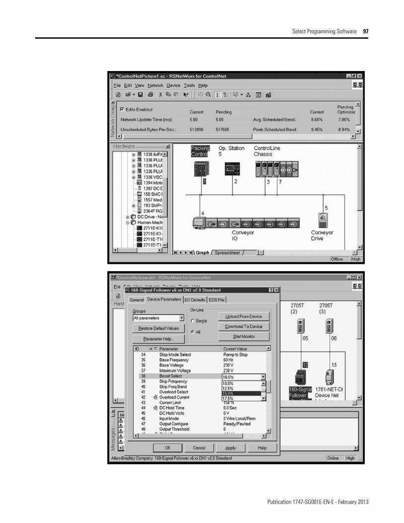
Publication 1747-SG001E-EN-E - February 2013
Select Programming Software 97
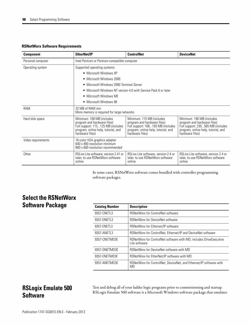
Publication 1747-SG001E-EN-E - February 2013
98 Select Programming Software
In some cases, RSNetWorx software comes bundled with controller programming software packages.
Select the RSNetWorx Software Package
RSLogix Emulate 500 Software
Test and debug all of your ladder logic programs prior to commissioning and startup. RSLogix Emulate 500 software is a Microsoft Windows software package that emulates
RSNetWorx Software Requirements
Component EtherNet/IP ControlNet DeviceNet
Personal computer Intel Pentium or Pentium-compatible computer
Operating system Supported operating systems:
• Microsoft Windows XP
• Microsoft Windows 2000
• Microsoft Windows 2000 Terminal Server
• Microsoft Windows NT version 4.0 with Service Pack 6 or later
• Microsoft Windows ME
• Microsoft Windows 98
RAM 32 MB of RAM minMore memory is required for large networks
Hard disk space Minimum: 108 MB (includes program and hardware files) Full support: 115...125 MB (includes program, online help, tutorial, and hardware files)
Minimum: 115 MB (includes program and hardware files) Full support: 168...193 MB (includes program, online help, tutorial, and hardware files)
Minimum: 190 MB (includes program and hardware files) Full support: 230...565 MB (includes program, online help, tutorial, and hardware files)
Video requirements 16-color VGA graphics adapter640 x 480 resolution minimum800 x 600 resolution recommended
Other RSLinx Lite software, version 2.41 or later, to use RSNetWorx software online
RSLinx Lite software, version 2.4 or later, to use RSNetWorx software online
RSLinx Lite software, version 2.4 or later, to use RSNetWorx software online
Catalog Number Description
9357-CNETL3 RSNetWorx for ControlNet software
9357-DNETL3 RSNetWorx for DeviceNet software
9357-ENETL3 RSNetWorx for Ethernet/IP software
9357-ANETL3 RSNetWorx for ControlNet, Ethernet/IP and DeviceNet software
9357-CNETMD3E RSNetWorx for ControlNet software with MD, includes DriveExecutive Lite software
9357-DNETMD3E RSNetWorx for DeviceNet software with MD
9357-ENETMD3E RSNetWorx for EtherNet/IP software with MD
9357-ANETMD3E RSNetWorx for ControlNet, DeviceNet, and Ethernet/IP software with MD

Publication 1747-SG001E-EN-E - February 2013
Select Programming Software 99
one or more SLC 500 processors. You determine which ladder programs you want to run and RSLogix Emulate scans the ladder logic like an actual processor.
RSLogix Emulate 500 software may be used with Windows 2000 (with Service Pack 2 or greater), Windows XP (with Service Pack 1 or greater), or Windows NT (version 4.00 with Service Pack 6A or greater). It is included in the RSLogix 500 Professional Programming Software package.

Publication 1747-SG001E-EN-E - February 2013
100 Select Programming Software
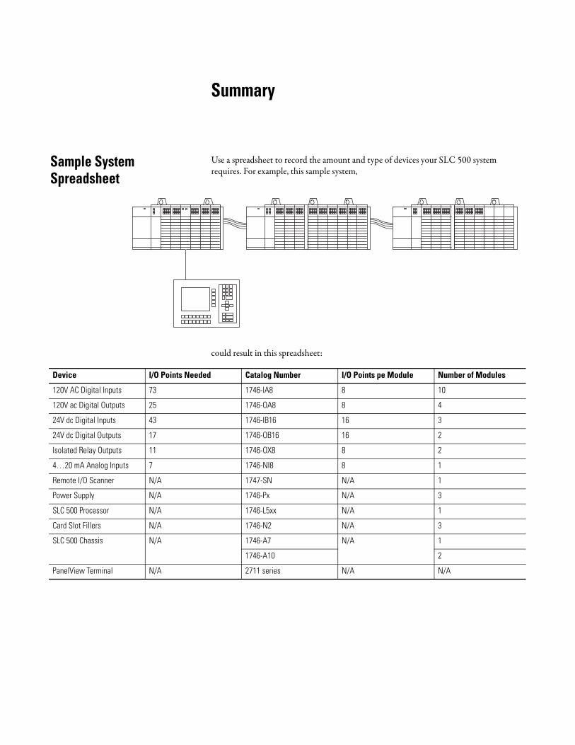
Summary
Sample System Spreadsheet
Use a spreadsheet to record the amount and type of devices your SLC 500 system requires. For example, this sample system,
could result in this spreadsheet:
Device I/O Points Needed Catalog Number I/O Points pe Module Number of Modules
120V AC Digital Inputs 73 1746-IA8 8 10
120V ac Digital Outputs 25 1746-OA8 8 4
24V dc Digital Inputs 43 1746-IB16 16 3
24V dc Digital Outputs 17 1746-OB16 16 2
Isolated Relay Outputs 11 1746-OX8 8 2
4…20 mA Analog Inputs 7 1746-NI8 8 1
Remote I/O Scanner N/A 1747-SN N/A 1
Power Supply N/A 1746-Px N/A 3
SLC 500 Processor N/A 1746-L5xx N/A 1
Card Slot Fillers N/A 1746-N2 N/A 3
SLC 500 Chassis N/A 1746-A7 N/A 1
1746-A10 2
PanelView Terminal N/A 2711 series N/A N/A
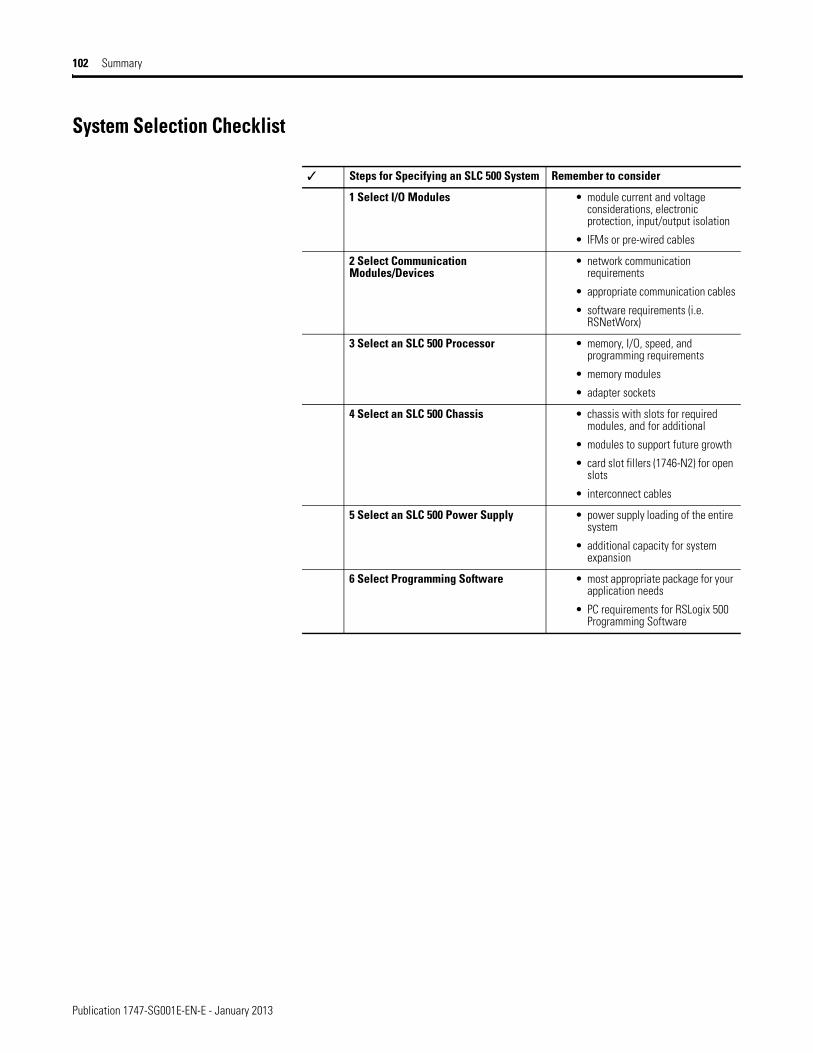
Publication 1747-SG001E-EN-E - January 2013
102 Summary
System Selection Checklist
✓ Steps for Specifying an SLC 500 System Remember to consider
1 Select I/O Modules • module current and voltage considerations, electronic protection, input/output isolation
• IFMs or pre-wired cables
2 Select Communication Modules/Devices
• network communication requirements
• appropriate communication cables
• software requirements (i.e. RSNetWorx)
3 Select an SLC 500 Processor • memory, I/O, speed, and programming requirements
• memory modules
• adapter sockets
4 Select an SLC 500 Chassis • chassis with slots for required modules, and for additional
• modules to support future growth
• card slot fillers (1746-N2) for open slots
• interconnect cables
5 Select an SLC 500 Power Supply • power supply loading of the entire system
• additional capacity for system expansion
6 Select Programming Software • most appropriate package for your application needs
• PC requirements for RSLogix 500 Programming Software
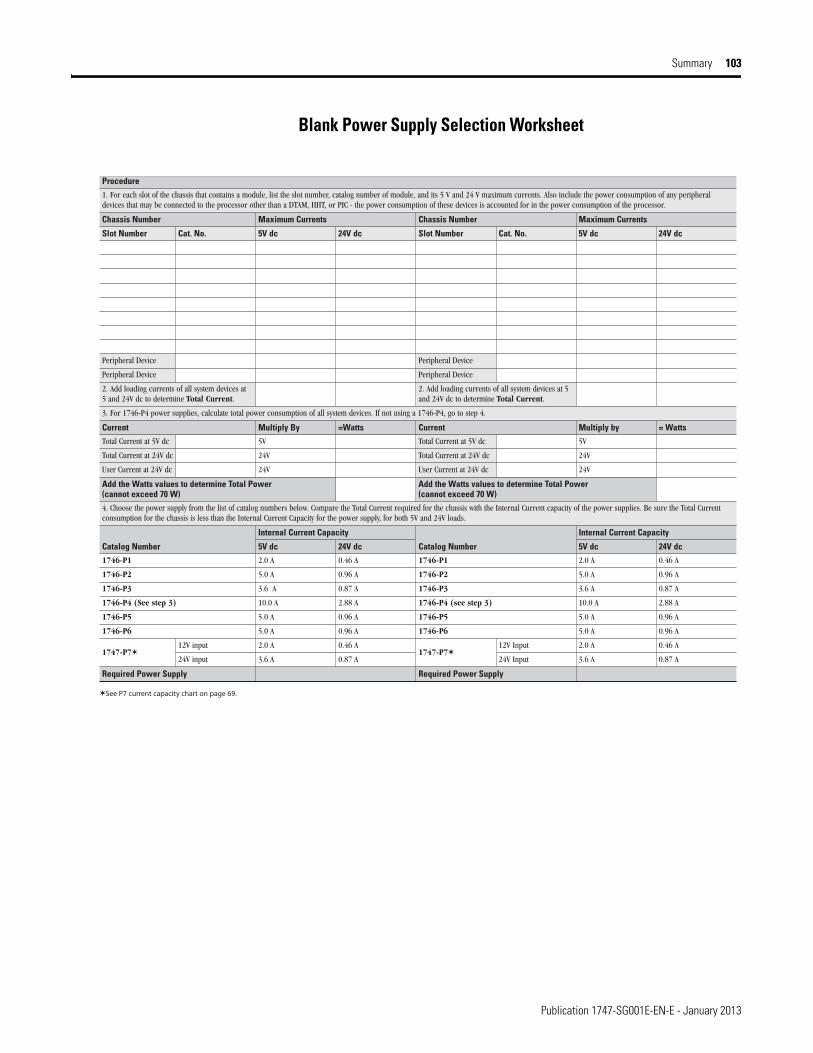
Publication 1747-SG001E-EN-E - January 2013
Summary 103
Blank Power Supply Selection Worksheet
Procedure
1. For each slot of the chassis that contains a module, list the slot number, catalog number of module, and its 5 V and 24 V maximum currents. Also include the power consumption of any peripheraldevices that may be connected to the processor other than a DTAM, HHT, or PIC - the power consumption of these devices is accounted for in the power consumption of the processor.
stnerruC mumixaMrebmuN sissahCstnerruC mumixaMrebmuN sissahC
Slot Number Cat. No. 5V dc 24V dc Slot Number Cat. No. 5V dc 24V dc
eciveD larehpirePeciveD larehpireP
eciveD larehpirePeciveD larehpireP
2. Add loading currents of all system devices at 5 and 24V dc to determine Total Current.
2. Add loading currents of all system devices at 5and 24V dc to determine Total Current.
3. For 1746-P4 power supplies, calculate total power consumption of all system devices. If not using a 1746-P4, go to step 4.
Current Multiply By =Watts Current Multiply by = Watts
Total Current at 5V dc 5V Total Current at 5V dc 5V
Total Current at 24V dc 24V Total Current at 24V dc 24V
User Current at 24V dc 24V User Current at 24V dc 24V
Add the Watts values to determine Total Power (cannot exceed 70 W)
Add the Watts values to determine Total Power (cannot exceed 70 W)
4. Choose the power supply from the list of catalog numbers below. Compare the Total Current required for the chassis with the Internal Current capacity of the power supplies. Be sure the Total Currentconsumption for the chassis is less than the Internal Current Capacity for the power supply, for both 5V and 24V loads.
Catalog Number
Internal Current Capacity
Catalog Number
Internal Current Capacity
5V dc 24V dc 5V dc 24V dc
1746-P1 2.0 A 0.46 A 1746-P1 2.0 A 0.46 A
1746-P2 5.0 A 0.96 A 1746-P2 5.0 A 0.96 A
1746-P3 3.6 A 0.87 A 1746-P3 3.6 A 0.87 A
1746-P4 (See step 3) 10.0 A 2.88 A 1746-P4 (see step 3) 10.0 A 2.88 A
1746-P5 5.0 A 0.96 A 1746-P5 5.0 A 0.96 A
1746-P6 5.0 A 0.96 A 1746-P6 5.0 A 0.96 A
1747-P712V input 2.0 A 0.46 A
1747-P712V Input 2.0 A 0.46 A
24V input 3.6 A 0.87 A 24V Input 3.6 A 0.87 A
Required Power Supply Required Power Supply
See P7 current capacity chart on page 69.
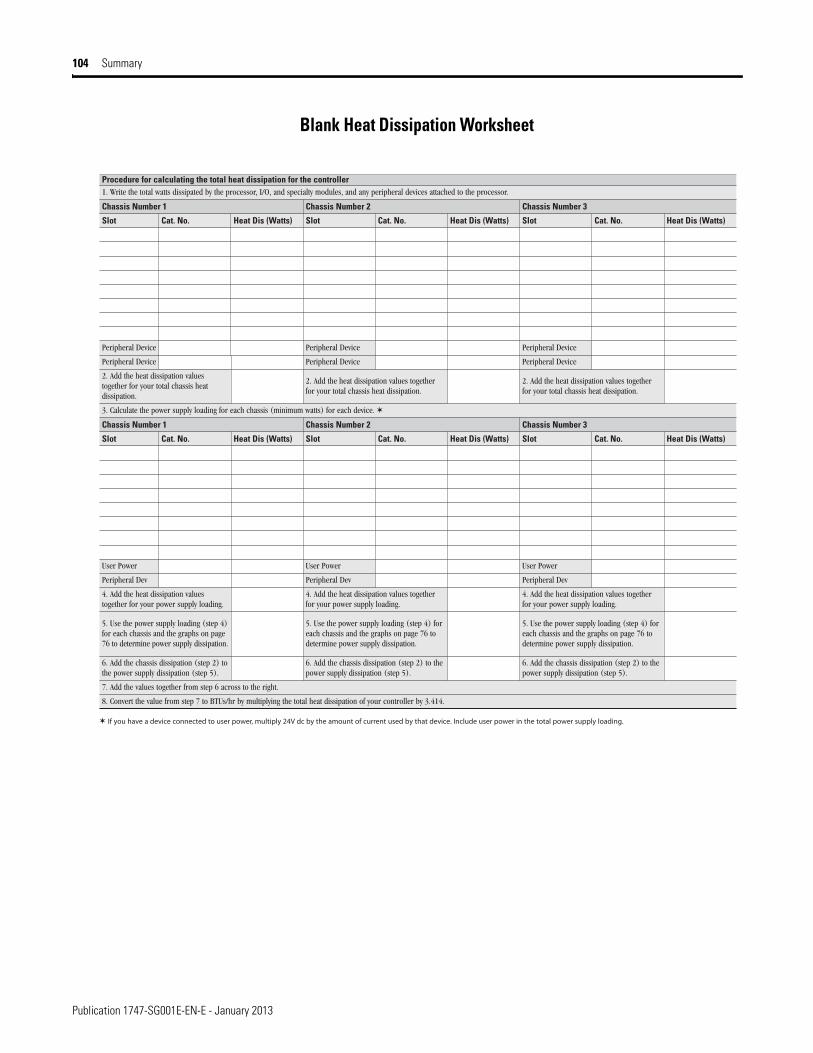
Publication 1747-SG001E-EN-E - January 2013
104 Summary
Blank Heat Dissipation Worksheet
Procedure for calculating the total heat dissipation for the controller 1. Write the total watts dissipated by the processor, I/O, and specialty modules, and any peripheral devices attached to the processor.
3 rebmuN sissahC2 rebmuN sissahC1 rebmuN sissahC
Slot Cat. No. Heat Dis (Watts) Slot Cat. No. Heat Dis (Watts) Slot Cat. No. Heat Dis (Watts)
eciveD larehpirePeciveD larehpirePeciveD larehpireP
eciveD larehpirePeciveD larehpirePeciveD larehpireP
2. Add the heat dissipation valuestogether for your total chassis heatdissipation.
2. Add the heat dissipation values togetherfor your total chassis heat dissipation.
2. Add the heat dissipation values togetherfor your total chassis heat dissipation.
3. Calculate the power supply loading for each chassis (minimum watts) for each device.
3 rebmuN sissahC2 rebmuN sissahC1 rebmuN sissahC
Slot Cat. No. Heat Dis (Watts) Slot Cat. No. Heat Dis (Watts) Slot Cat. No. Heat Dis (Watts)
rewoP resUrewoP resUrewoP resU
veD larehpirePveD larehpirePveD larehpireP
4. Add the heat dissipation valuestogether for your power supply loading.
4. Add the heat dissipation values togetherfor your power supply loading.
4. Add the heat dissipation values togetherfor your power supply loading.
5. Use the power supply loading (step 4)for each chassis and the graphs on page76 to determine power supply dissipation.
5. Use the power supply loading (step 4) foreach chassis and the graphs on page 76 todetermine power supply dissipation.
5. Use the power supply loading (step 4) foreach chassis and the graphs on page 76 todetermine power supply dissipation.
6. Add the chassis dissipation (step 2) tothe power supply dissipation (step 5).
6. Add the chassis dissipation (step 2) to thepower supply dissipation (step 5).
6. Add the chassis dissipation (step 2) to thepower supply dissipation (step 5).
7. Add the values together from step 6 across to the right.
8. Convert the value from step 7 to BTUs/hr by multiplying the total heat dissipation of your controller by 3.414.
If you have a device connected to user power, multiply 24V dc by the amount of current used by that device. Include user power in the total power supply loading.

Rockwell Otomasyon Ticaret A.Ş., Kar Plaza İş Merkezi E Blok Kat:6 34752 İçerenköy, İstanbul, Tel: +90 (216) 5698400
Publication 1747-SG001E-EN-E - February 2013 106Copyright © 2013 Rockwell Automation, Inc. All rights reserved. Printed in the U.S.A.
Rockwell Automation Support
Rockwell Automation provides technical information on the Web to assist you in using its products. At http://www.rockwellautomation.com/support/, you can find technical manuals, a knowledge base of FAQs, technical and application notes, sample code and links to software service packs, and a MySupport feature that you can customize to make thebest use of these tools.
For an additional level of technical phone support for installation, configuration, and troubleshooting, we offer TechConnect support programs. For more information, contact your local distributor or Rockwell Automation representative, or visit http://www.rockwellautomation.com/support/.
Installation Assistance
If you experience a problem within the first 24 hours of installation, review the information that is contained in this manual.You can contact Customer Support for initial help in getting your product up and running.
New Product Satisfaction Return
Rockwell Automation tests all of its products to ensure that they are fully operational when shipped from the manufacturing facility. However, if your product is not functioning and needs to be returned, follow these procedures.
Documentation Feedback
Your comments will help us serve your documentation needs better. If you have any suggestions on how to improve this document, complete this form, publication RA-DU002, available at http://www.rockwellautomation.com/literature/.
United States or Canada 1.440.646.3434
Outside United States or Canada
Use the Worldwide Locator at http://www.rockwellautomation.com/support/americas/phone_en.html, or contact your local Rockwell Automation representative.
United States Contact your distributor. You must provide a Customer Support case number (call the phone number above to obtain one) to your distributor to complete the return process.
Outside United States Please contact your local Rockwell Automation representative for the return procedure.