chapter 6 irrigation system design - usda · chapter 6 irrigation system design ... procedure for...
TRANSCRIPT

Chapter 6 Irrigation System Design
Contents: FL652.0605a Fixed-Solid Set Sprinkler Irrigation System FL6-1 General FL6-1 Design Criteria FL6-1 Example Problem FL6-1 Layout Considerations FL6-5 Construction Requirements FL6-5
FL652.0605b Microirrigation Systems FL6-19 General FL6-19 Design Criteria FL6-19 Example Problem FL6-19 Material and Construction Requirements FL6-22 Computer Design of Pipelines FL6-22
FL652.0605c Center Pivot Sprinkler Irrigation Systems FL6-43 General FL6-43 Design Criteria FL6-43 Example Problem FL6-43 Construction Requirements FL6-45 Layout Considerations FL6-45 Procedure for determining Gross Application of Center Pivot
Sprinkler Systems FL6-45
Head Loss Using Pipeline Sizing Worksheet FL6-61
FL652.0605d Traveling Gun Sprinkler Irrigation Systems FL6-53 General FL6-53 Design Criteria FL6-53 Example Problem FL6-53 Layout Considerations FL6-55 Construction Requirements FL6-55 FL652.0605e Subirrigation – Flow Through Systems FL6-63 General FL6-63 Design Criteria FL6-63 Example Problem FL6-63 FL652.0605f Subirrigation – Underground Conduit FL-71 General FL6-71 Design Criteria FL6-71 Design Procedures FL6-71 Example Problem FL6-71 Layout Considerations FL6-73
(210-vi-NEH, FL Amendment, FL-12, May 2006) FL6-i

Chapter 6 Irrigation System Design Part 652 Irrigation Guide
Construction Requirements FL6-73 System Operation FL6-73
Tables FL6A-1 Typical Sprinkler Manufacturer’s Data FL6-5
FL6B-1 Values to use in estimating the optimum manifold on a sloping field
FL6-41
FL6B-2 Irrigation Screen Filters: Mesh or Sieve Opening in Inches or Millimeters
FL6-42
FL6D-1 Guide for Flexible Irrigation hose Selection FL6-56
FL6F-1 Relief Line Spacing Tables FL6-79
Figures FL6B-1a Performance Curve for Green Base Spray Emitter FL6-40
FL6B-1b Loss of Pressure Due to Friction Along a Pipeline Having Only One Size of Pipe with Uniform Outlets
FL6-40
FL6D-1 Irrigation Hose Loss Pressure per 100 Feet FL6-56
FL6E-1 Pump Rating Curves FL6-67
Exhibits FL6A-1 Irrigation System Sprinkler Permanent/Solid Set Design Data Sheet
FL6-6
FL6A-2 Example Problem Using Pipeline Sizing Worksheet
FL6-15
FL6A-3 Irrigation System Schematic FL6-16
FL6A-4 Irrigation System Schematic FL6-17
FL6B-1 Microirrigation System Data Sheet for Orchard Crops
FL6-23
FL6B-2 Example Problem Using Pipeline Sizing Worksheet FL6-33
FL6C-1 Irrigation Sprinkler Center Pivot Design Data Sheet FL6-48
FL6C-2 Head Loss Using Pipeline Sizing Workbook FL6-52
FL6D-1 Irrigation System Sprinkler Traveling Gun Design Data Sheet
FL6-57
FL6D-2 Head Loss Using Pipeline Sizing Worksheet FL6-61
FL6-ii (210-vi-NEH, FL Amendment, FL-12, May 2006)

Chapter 6 Irrigation System Design Part 652 Irrigation Guide
FL6E-1 Low Head Plastic Irrigation Pipeline Plan FL6-69
FL6F-1 Plan of Subsurface Irrigation – Underground Conduit & Mainline Size Determination
FL6-75
FL6F-2 Drain Chart – Corrugated Plastic Drain Tubing FL6-78
(210-vi-NEH, Amendment FL-12, May 2006) FL6-iii

Chapter 6 Irrigation System Design
(210-vi-NEH, Amendment FL-11, September 2003) FL6-1
FL652.0605a - Fixed-Solid Set Sprinkler Irrigation System GeneralThe example problem in this chapter is intended to illustrate the procedure to follow in the design of permanent and solid-set irrigation systems. It is understood that one example cannot illustrate all design situations or alternatives to consider when designing a permanent or a solid-set irrigation system. Design CriteriaDesign criteria for permanent and solid-set irrigation systems is contained in NRCS conservation practice standard, Irrigation System, Sprinkler, Code 442, for Florida. All sprinkler irrigation systems must be designed in accordance with the criteria contained in Code 442. Example Problem The following example problem is intended to cover the basic design steps to follow in the design of permanent/solid-set sprinkler irrigation systems. Form FL-ENG-442A "Irrigation System Sprinkler Permanent/Solid-Set Design Data Sheet" (Exhibit FL6A-1) is used which is a useful tool in designing and recording data. Given: 1. Location: Sebring, Florida (Highlands
County-Climatic Zone 5). 2. Field Shape: 1320 feet east to west by 660
feet north to south (20 acres). 3. Soil: Lakeland fine sand. 4. Crop: Citrus. 5. Row direction and spacing: Rows run north
to south 30 feet apart. 6. Plant spacing along row: 20 feet. 7. Well information: 8-inch well without pump.
Power unit planned is electric, 3 phase. Static water level is at 75 feet below ground surface.
8. Owner would like to operate system about 12 hours per day using normal shut off valves. Irrigation to be done at night.
9. All pipe to be buried. Solution: The item numbers mentioned in the step by step solution refer to the items on form FL-ENG-442A in Exhibit FL6A-1. Step 1: Complete Items 1-4. These items provide an inventory of pertinent data at the site. Step 2: Complete Item 5. Make a drawing to scale of the field locating buildings, trees, well and other features. Step 3: Determine the allowable application rate. Lakeland fine sand is a deep sand with an intake rate of 3 inches per hour, as taken from Florida Irrigation Guide (FIG), Chapter 2, Table 2-2. Code 442 recommends a minimum application rate of 0.10 inches per hour. Therefore, the range should be between 0.10 in./hr and 3.0 in./hr. Step 4: Complete Item 6, except for acreage to be grown which will be discussed later. The moisture extraction root depths (ft) can be taken from Table FL3-2 of NEH, Part 652, Irrigation Guide. The peak consumptive use rate (in./day) is to be taken from NEH Part 652, Table FL4-7. Step 5: Complete Item 7. Obtain the soil series from a published soil survey report or an on-site investigation. The moisture holding capacity is taken from FIG Table 2-2. Step 6: Complete the following parts of Item 8.
a. Available water capacity (AWC) within the root zone is the product of the root zone moisture extraction depth (60 in.) times the weighted moisture holding capacity of the soil (.062 in./in.). AWC = (60 in.)x(0.062 in./in.) = 3.72 in.
b. The percent depletion allowed prior to irrigation is 30% for citrus as set forth in NEH Part 652 Chapter FL3.
c. The net water applied per irrigation (in.) is the product of the percent depletion allowed prior to irrigation times the water available within the root zone. The net water applied per irrigation this example is (0.30)x(3.72 in.) = 1.12 in.
d. The water application efficiency (%) is 75%. Conservation practice standard,

Chapter 6 Irrigation System Design Part 652 Irrigation Guide
Irrigation System, Sprinkler Code 442 provides the maximum efficiencies to be used.
e. The gross water applied per irrigation (in.) is found by dividing the net water applied per irrigation of 1.12 inches by the water application efficiency of 75%. Gross water applied = 1.12 in. ÷ 0.75 = 1.5 in.
f. The irrigation interval (days) is determined by dividing the net water applied per irrigation (1.12 in.) by the crop peak consumptive use rate (0.20 in/day). Irrigation interval = 1.12 in. ÷ 0.20 in./day = 5.6 days.
g. Normally, the irrigation period in days to be used in the formula for determining QR is the irrigation interval 5.6 days determined above. However, in this example the field was broken up into four irrigation units of 5 acres each which resulted in one unit being irrigated each day. Therefore, one (1) day was entered in each column for the irrigation period and 5 acres per irrigation unit in Item 6. The advantages of dividing the field into four units is that a smaller pump can be used and a smaller well capacity is required.
h. Twelve (12) hours operating per day was requested by the owner.
Step 7. Determine the quantity of water required QR for each irrigation unit. Use the formula: QR = 453 Ad
FH Where QR = minimum required discharge capacity in gallons per minute A = acreage of the design area d = gross depth of application in inches F = number of days allowed for completion of
one irrigation H = number of actual operating hours per day
QR= 453 x 5 acres x 1.5 in. gross application
12 hrs operating per day x 1 day per irrigation
QR = 283 gpm
Note that the QR should not exceed the well capacity. In situations where the well capacity is exceeded, the irrigation unit acreage would need to be decreased or the operating hours per day increased or a well of higher capacity would have to be installed. Step 8. Select a sprinkler spacing that is compatible with the tree spacing. Some alternatives would be 40 ft by 60 ft or 60 ft by 60 ft. The 60 ft by 60 ft in a square pattern was tentatively selected. Step 9. Check the sprinkler spacing requirement in the Code 442. Since irrigation will be done at night, no wind is considered resulting in a requirement that the sprinkler spacing be no greater than 65% of the wetted diameter. Step 10. Select a sprinkler. There are two requirements for which the sprinkler selection is to be based: (1) the wetted diameter must be at least 92.3 feet. This is computed by dividing the sprinkler spacing of 60 feet by the required maximum spacing of 65% of the wetted diameter (60 ft ÷ 0.65 = 92.3 ft); (2) the minimum required gpm of the sprinkler. The following formula us used to determine the gpm/spk: Application rate (in./hr) = gpm/spk x 96.3
S x L Where S = Spacing of sprinklers along lateral
L = Spacing between laterals in feet For a tentative application rate, divide the gross application of 1.5 inches by the hours operating per day (12 hrs) which results in 0.125 inches per hour. Now solve the formula for gpm/spk: gpm/spk = 0.125 in./hr x 60 ft x 60 ft
96.3 gpm/spk = 4.67 gpm With the two sprinkler requirements of 4.67 gpm and 92.3 feet wetted diameter refer to the sprinkler manufacturer's charts. Table FL6A-1 shows a typical manufacturer's sprinkler data and was used to select the sprinkler. The sprinkler selected has a capability of 4.72 gpm @ 45 psi with a wetted diameter of 96 feet which meets the criteria. The nozzle size is 5/32 inches. This data was entered in Item 10.
FL6-2 (210-vi-NEH, Amendment FL-11, September 2003

Chapter 6 Irrigation System Design Part 652 Irrigation Guide
Step 11. Complete Item 9. (a). Application rate is recomputed using the formula: Application rate (in./hr) =
gpm/spk x 96.3 = 4.72 x 96.3 = 0.126 S x L 60 x 60
(b). Time per lateral or unit set in hours is computed by dividing the gross application of 1.5 in. by the application rate of 0.126 in./hr. Time per lateral set = 1.5 in. ÷ 0.126 in./hr = 11.9 hr. (c). Determine the number of sprinklers per unit. Divide the field using the drawing prepared in Step 2 into 4 as nearly equal units as possible. Place the sprinklers, pipe layout and valves on the plan. Label each unit and place it on the drawing. Count the number of sprinklers per unit and enter in Item 9. Units 1 and 4 have 60 sprinklers while units 2 and 3 have 61 sprinklers. (d). Determine the actual gpm/unit, QA per unit. Multiply the number of sprinklers per unit times the gpm/spk to determine gpm/unit. Units 1 & 4: 60 spk x 4.72 gpm/spk =
283.2 gpm Units 2 & 3: 61 spk x 4.72 gpm/spk =
287.9 gpm Step 12. Determine the Total Dynamic Head. Refer to Item 11, as each of the following points are discussed: (a). Size the lateral and submain to determine its head loss. Usually the longest lateral and submain is used to determine the head loss within the irrigation unit. However, ground elevation changes may sometimes cause the maximum head loss to occur elsewhere. This will be discussed a little later in this step. Sheets 5 and 6 of Exhibit FL6A-1, Pipe Sizing Data Sheet, FL-ENG-430, can be used for this purpose or the Pipeline Sizing Workbook (Excel spreadsheet program) as shown in Exhibit FL6A-2. Using FL-ENG-430, the gpm for the lateral and submain was listed in a cumulative manner beginning with the last sprinkler. The length of pipe carrying the corresponding gpm was then listed. Then using friction loss tables in Chapter 16, the pipe was sized and corresponding
friction head loss (HLf) in ft/100 ft listed on the data sheet. The pipe is sized so that the velocity of water flow through the pipe is less than or equal to 5 fps. The total friction head loss is determined by multiplying the HLf (ft/100 ft) x the pipe length (ft) and summing the results. The elevation difference (zero in this example due to a level field) is then totaled and added to the total friction head loss to obtain the total head loss in the lateral. The summation for Unit 4 of 9.14 feet was used in the design. Elevation difference of natural ground between the risers and within an irrigation unit was not significant in the example discussed. However, it must be evaluated for each design as it can, to a great extent, affect the layout of the irrigation unit and the pipe sizing. It affects the layout because the nozzle pressure must be maintained within certain limits in each irrigation unit. These limits are discussed in Step 12(b). The effect that elevation difference has on pipe sizing can best be explained using an example. For instance, if a lateral is to be installed downhill from the mainline, a smaller pipe with higher friction head loss may be used. The elevation difference is downhill (increase in pressure) which offsets the decrease in pressure due to friction head loss. An increasing elevation plays a reverse role often resulting in a larger diameter pipe. The multiple outlet factor (see Table 11-15, NEH Part 623, Irrigation, Chapter 11), which could not be used to advantage in this problem, can be used to determine the friction head loss (hf) in a length of pipe (L) of one diameter. For example, if the entire lateral was designed to be 1 ½ in. diameter, then with a flow of 26.7 gpm it would have a (J) of 2.78 ft/100ft. With six outlets in the lateral, the multiple outlet factor (F) from Table 11-15 is 0.44. The total head loss in the lateral would be: hf = (JxFxL) / 100. (b). The head loss for the irrigation unit is then modified so that the theoretical mid-system sprinkler is operating at the design nozzle pressure. This provides for a more balanced system in that the sprinkler closer to the pump operates at a pressure a little higher than the design nozzle pressure and the farthest sprinkler a little lower in pressure. The head loss is modified by multiplying the summation of 9.14 feet x 0.5 = 4.57 feet. The sprinklers within an
(210-vi-NEH, Amendment FL-11, September 2003) FL6-3

Chapter 6 Irrigation System Design Part 652 Irrigation Guide
irrigation unit for citrus must operate at a pressure within 20% (± 10%) of the design operating pressure as required by conservation practice standard, Irrigation System, Sprinkler Code 442. In this case, with the design operating pressure at 45 psi, the allowable variation in sprinkler operating pressure is:
0.2 x 45 psi = 9.0 psi = 20.8 feet Therefore, 45 psi ± 10% = 40.5 psi and 49.5 psi for the minimum and maximum sprinkler operating pressure. The maximum allowable head loss in the system or unit is 20.8 feet. It may be helpful at this point to sketch a schematic of the system as shown in Exhibit FL6A-3 to determine the high and low pressure in the system. (c). Size the mainline and determine the head loss. Item 11 was used for sizing and determining the mainline head loss. The 6 inch diameter main with 283.2 gpm has a friction head loss of 0.47 ft/100 ft. Total head loss is equal to 0.47 ft/100 ft x 345 feet = 1.62 feet. The 1.62 feet is equal to 0.70 psi. If elevation differences had been encountered, the pipe sizing data sheet would have been used. (d). Design sprinkler nozzle pressure. The 45 psi sprinkler operating pressure was determined in Item 10. Remember that this is the operating pressure of the theoretical mid-sprinkler of the irrigation unit. (e). Miscellaneous and fitting friction losses. This can be computed using the formula
h = (KV 2/2g)
where values of K for head loss coefficients for fittings and special conditions are in Chapter 16. However, this is usually estimated to be within a range of 1.3 psi to 3.5 psi depending on the complexity of the system. This example was estimated to have about 1.3 psi head loss for miscellaneous and fitting losses. (f). Riser height. The height required to get the sprinkler above the vegetation to prevent distortion of the water. In this case, 21 feet is required. (g). Pump discharge pressure. This is the pressure the pump must produce at its discharge side so that the theoretical mid-sprinkler of the irrigation unit is operating at its design operating
pressure of 45 psi. To obtain the pump discharge pressure the preceding items were totaled as follows: Lateral & sub-main friction losses = 2.0 psi Mainline friction losses = 0.7 psi Nozzle pressure = 45.0 psi Miscellaneous & fitting friction
losses = 1.3 psi Riser height = 9.1 psiPump discharge pressure = 58.1 psi (h). Pumping lift. This is discussed in Chapter 6. It is the vertical distance the pump must lift the water in the well to reach the ground level or in the case of a centrifugal pump the vertical distance from the water source to the pump discharge. The pump-drawdown is considered in determining the pumping lift. This example has the static water level at 75 feet with 15 feet of drawdown when pumping. Therefore the pumping lift is 75 feet + 15 feet = 90 feet which is equal to 39.0 psi. (i). Total dynamic head (TDH). This is the total head loss that the pump must operate against in order for it to perform the required work. The pump discharge pressure 58.1 psi + pumping lift 39 psi = 97.1 psi TDH. This is usually expressed in feet which would be 224.2 feet TDH. Step 13. Complete Item 12, Pump Requirement. This is the maximum gpm the pump must produce at a given TDH. From Item 9, the maximum QA for an irrigation unit is 287.9 gpm. The TDH from the preceding section is 224 feet. Therefore, the pump requirement would be expressed as 287.9 gpm at 224.2 feet TDH. Step 14. Complete Item 13. Check the sprinkler pressure variation within the system (Irrigation Units) against the allowable. This was discussed earlier under Step 12(b). It may be helpful at this point to again sketch a schematic of the system (irrigation unit) and label losses throughout the system as shown in Exhibit FL6A-4 to determine the high and low pressure in the system. The actual is found by using sheet 4 of 7 of Exhibit FL6A-1. The actual nozzle pressure of the closer sprinkler is the pump discharge pressure (58.1 psi) - the mainline loss (0.70 psi) – actual total lateral and and submain losses (0.23 psi) - miscellaneous and fitting friction losses (1.3 psi) - the riser
FL6-4 (210-vi-NEH, Amendment FL-11, September 2003

Chapter 6 Irrigation System Design Part 652 Irrigation Guide
height loss (9.1 psi) = 46.8 psi. The actual nozzle pressure of the farthest nozzle is the pump discharge pressure (58.1 psi) - the mainline loss ( 0.70 psi) - miscellaneous and fitting friction losses (1.3 psi) - the riser height loss (9.1 psi) - actual total lateral and sub-main losses (4.06 psi) = 43.0 psi.
The allowable nozzle pressure as taken from Step 12(b) is 40.5 psi (minimum) and 49.5 psi (maximum). The actual nozzle pressure of 43.0 psi and 46.8 psi is within this range.
Table FL6A-1. Typical Sprinkler Manufacturer's Data. Highest point of stream is 7' above nozzle.* Nozzle size, in.
7/64 1/8 9/64 5/32 11/64 psi @ Nozzle
diam gpm diam gpm diam gpm diam gpm diam gpm 25 78 1.73 82 2.25 85 2.90 88 3.52 90 4.24 30 79 1.89 84 2.47 87 3.16 90 3.85 92 4.64 35 80 2.05 85 2.68 89 3.40 92 4.16 94 5.02 40 81 2.20 86 2.87 91 3.63 94 4.45 96 5.37 45 82 2.32 87 3.05 92 3.84 96 4.72 98 5.70 50 83 2.44 88 3.22 93 4.04 98 4.98 100 6.01 55 84 2.56 89 3.39 94 4.22 100 5.22 102 6.30 60 85 2.69 90 3.55 95 4.38 101 5.44 103 6.56
+Standard Nozzle. *Shown for standard nozzle at normal operating pressure. Area shaded in chart is the recommended working pressure for best distribution.
Layout Considerations Items that must be considered in the layout of a permanent and solid-set irrigation system are as follows: a. Soil limitations which may affect the ease of
installation such as cut banks caving, depth to rocks and wetness.
b. Plant spacing and row direction so that riser can be properly located.
c. Maximum height of plants for determining riser height.
d. Location of obstacles such as ponds, fences, overhead power lines and buried electrical and gas lines which are safety hazards.
e. Topography which may affect the layout of the system and valve arrangement so that each irrigation unit can be operated within the allowable pressure variation.
Construction Requirements Construction items that must be checked to be assured of a quality installation are as follows: a. The depth of cover over the buried main line
must be adequate for protection from vehicular traffic and the farming operation.
b. Thrust block dimensions, location and alignment to prevent pipe joint separation.
c. Location and size of air vents and pressure relief valve. Riser function as air vents but others may be required if a pipeline has a summit with no riser.
d. Riser material, diameter, height and spacing. e. Sprinkler model and size nozzle. Location of
part circle sprinklers if planned. f. Location and size of valves which serve each
irrigation unit. g. Depth of cover over buried pipe. h. Verify the pipe requirements such as SDR
number, pressure rating, ASTM designation, PVC material, pipe diameter and if PIP or IPS pipe.
i. Check valve installed at pump discharge. j. Verify pump, motor and well size. Then
check the nozzle pressure and variation within each irrigation unit using a pressure gauge with a pitot tube.
(210-vi-NEH, Amendment FL-11, September 2003) FL6-5

Chapter 6 Irrigation System Design Part 652 Irrigation Guide
FL6-6 (210-vi-NEH, Amendment FL-11, September 2003)
Exhibit FL6A-1 Irrigation System Sprinkler Permanent/Solid Set Design Data Sheet U.S. Department of Agriculture FL-ENG-442A Natural Resources Conservation Service 3/00 Sheet 1 of 7
IRRIGATION SYSTEM SPRINKLER PERMANENT/SOLID-SET DESIGN DATA SHEET
Cooperator: T.O. Dry Location: 2 mile S of Sebring, W side of 27 Conservation District: Highlands Field Office: Sebring Identification No.: Field No.: 1 1. Design area: 20 acres Description of soils: 0-80 inches is sand, fine sand
Soil Series: Lakeland fine sand Soil Series: Soil Series: Soil Depth Average AWC Soil Depth Average AWC Soil Depth Average AWC
(in.) (in./in.) (in.) (in./in.) (in.) (in./in.) 0-12 0.065 12-24 0.065 24-36 0.065 36-48 0.061 48-60 0.055
Design Soil Series: Lakeland 2. Crops:
Crop Acres Planting Date Maturity Date Citrus 20
Total acres 20
3. Water Supply: Source of supply: (stream, well, reservoir, etc.) 8” diameter well Reservoir: Storage N.A. ac-ft Available for Irrigation N.A. ac-ft
Well: Static Water Level 75 ft Measured Capacity 500 gpm @ 15 ft drawdown Design Pumping Lift 90 ft
Stream: Measured flow (season of peak use) N.A. gpm
Quality of water (Evidence of suitability. Area of known water quality or water analysis attached). Good Distance of water supply source to field 0 feet 4. Type of power unit and pump to be used: The power unit planned is a 60 cycle, 460 volt, 3 phase, part wind starting squirrel cage induction vertical-hollow shaft electrical motor. The pump is a deep well turbine pump, direct drive.

Chapter 6 Irrigation System Design Part 652 Irrigation Guide
Exhibit FL6A-1 Irrigation System Sprinkler Permanent/Solid Set Design Data Sheet U.S. Department of Agriculture FL-ENG-442A Natural Resources Conservation Service 3/00 Sheet 2 of 7
(210-vi-NEH, FL Amendment, FL-11, September 2003) FL6-7
5. Map of design area - Scale 1” = __________ feet. Sketch map on grid or attach photo or overlay. . . . . . . . . . . . .. . . . . . . . . . . . . . . . . . . . . . . . . . . . . . . . . . . . . . . .. . . . . . . . . . . . . . . . . . . . . . . . . . . . . . . . . . . . . . . .. . . . . . . . . . . . . . . . . . . . . . . . . . . . . . . . . . . . . . . .. . . . . . . . . . . . . . . . . . . . . . . . . . . . . . . . . . . . . . . .. . . . . . . . . . . . . . . . . . . . . . . . . . . . . . . . . . . . . . . .. . . . . . . . . . . . . . . . . . . . . . . . . . . .
. . . . . . . . . See attached drawing Sheet 7 of 7. . . . . . . . . . . . . . . . . . . . . . .. . . . . . . . . . . . . . . . . . . . . . . . . . . . . . . . . . . . . . . .. . . . . . . . . . . . . . . . . . . . . . . . . . . . . . . . . . . . . . . .. . . . . . . . . . . . . . . . . . . . . . . . . . . . . . . . . . . . . . . .. . . . . . . . . . . . . . . . . . . . . . . . . . . . . . . . . . . . . . . .. . . . . . . . . . . . . . . . . . . . . . . . . . . . . . . . . . . . . . . .. . . . . . . . . . . . . . . . . . . . . . . . . . . . . . . . . . . . . . . .. . . . . . . . . . . . . . . . . . . . . . . . . . . . . . . . . . . . . . . .. . . . . . . . . . . . . . . . . . . . . . . . . . . . . . . . . . . . . . . .. . . . . . . . . . . . . . . . . . . . . . . . . . . . . . . . . . . . . . . .. . . . . . . . . . . . . . . . . . . . . . . . . . . . . . . . . . . . . . . .. . . . . . . . . . . . . . . . . . . . . . . . . . . . Map should show: Material-Mains and Manifolds
a. Source of water Nominal, PIP SDR Material Pressure Inside Total Minimumb. Elevation differences Pipe Size or No. (PVC 1120 Rating Diam. Length, Depth of c. Row direction in. IPS etc.) psi in. feet Cover, in.d. Sprinkler system layout e. Plan of Operations f. Field Obstructions
(canals, trees, fences buildings, etc.)
g. North arrow

Chapter 6 Irrigation System Design Part 652 Irrigation Guide
Exhibit FL6A-1 Irrigation System Sprinkler Permanent/Solid Set Design Data Sheet U.S. Department of Agriculture FL-ENG-442A Natural Resources Conservation Service 3/00 Sheet 3 of 7
FL6-8 (210-vi-NEH, FL Amendment, FL-11, September 2003)
IRRIGATION UNIT NUMBER 6. Crop Information 1 2 3 4 5 Kind of Crop Citrus Citrus Citrus Citrus Acreage to be grown (acres)1/ 5 5 5 5 Rooting depth (in.) 60 60 60 60 Peak use rate (in./day) 0.2 0.2 0.2 0.2 7. Soil Information Weighted AWC for rooting depth (in./in.) 0.062 0.062 0.062 0.062 Basic intake rate (in./hr.) 3.0 3.0 3.0 3.0 8. Design Procedure AWC within root zone (in.) 3.72 3.72 3.72 3.72 % Depletion allowed prior to irrigation 30 30 30 30 Net water applied per irrigation (in.) 1.12 1.12 1.12 1.12 Water application efficiency (%) 75 75 75 75 Gross water applied per irrigation (in.) 1/ 1.5 1.5 1.5 1.5 Irrigation interval (days) 5.6 5.6 5.6 5.6 Irrigation period (days per irrigation) 1/ 1 1 1 1 Hours operating per day 1/ 12 12 12 12 QR = Quantity of water required (gpm) 1/ 283 283 283 283 9. Irrigation Unit Design Application Rate (in./hr) 2/ 0.13 0.13 0.13 0.13 Time per lateral or unit set 3/ 11.5 11.5 11.5 11.5 Number of sprinklers per unit 60 61 61 60 QA 4/ = Quantity of water actual (gpm/unit) 283.2 287.9 287.9 283.2
10. Sprinkler Specifications: a. Sprinkler spacing 60 ft. Lateral spacing 60 ft. b. Nozzle size 5/32 x __________ wetted diameter 96 ft. c. Capacity 4.72 gpm @ 45 psi or 103.9 ft.
1/ QR = 453 x ______ acres x _____ in. gross application = _______ gpm _____ hrs. opr. per day x ____ days per irrigation
2/ Application rate (in./hr.) = gpm/spk x 96.3 (MUST BE < BASIC INTAKE RATE) S X L Where S = Spacing of sprinklers along lateral in feet. L = Spacing between laterals in feet.
3/ Time per lateral or unit set = Gross water applied per irrigation (in.) Application Rate (in./hr.)
4/ QA = maximum unit gpm = gpm/spk x number of sprinklers per unit, Must > QR

Chapter 6 Irrigation System Design Part 652 Irrigation Guide
Exhibit FL6A-1 Irrigation System Sprinkler Permanent/Solid Set Design Data Sheet U.S. Department of Agriculture FL-ENG-442A Natural Resources Conservation Service 3/00 Sheet 4 of 7
(210-vi-NEH, FL Amendment, FL-11, September 2003) FL6-9
11. Determining Total Dynamic Head 5/
Kind of Pipe
Design
Capacity
IPS: PIP:
Other ___
Friction Head
Total Head Loss
Total Head Loss, HL
Main Mani-Fold
Lateral (gpm) Diameter (in.)
Length (ft)
Loss (ft/100ft)
HL (ft)
(ft) (psi)
xxxx 3 3 (See Attached Pipe Sizing 9.1 xxxx xxxx xxxx Data Sheet 6 of 7 xxxx xxxx xxxx xxxx xxxx xxxx xxxx xxxx xxxx xxxx xxxx
6/ Sum HL 9.1 x 0.5= 4.6 2.0 3 xxxx xxxx 283.2 6 345 0.47 xxxx 1.6 0.7 xxxx xxxx xxxx xxxx xxxx xxxx xxxx xxxx xxxx xxxx xxxx xxxx
Design Sprinkler Nozzle Pressure 104.0 45.0Miscellaneous Losses 3.0 1.3Riser Height 21.0 9.1Pump Discharge Pressure 134.2 58.1Pumping Lift 90.0 39.0Total Dynamic Head, TDH 224.2 97.1
12. Pump Requirements: 288 gpm @ 97.1 psi or 224.2 ft or head
13. Check allowable pressure variation that will provide a 20% or less total variation of the design sprinkler pressure.
Allowable pressure variation = 40.5 psi to 49.5 psi = 9.0 psi variation Actual pressure variation 7/ = 43.0 psi to 46.8 psi = 3.8 psi variation
14. Remarks
5/ Use pipe sizing sheets where elevation differences are present and/or additional data lines needed. 6/ Sets optimum emitter pressure at a theoretical mid-system sprinkler. 7/ Consider elevations and location. Adjust 6/ if possible to stay within allowed variation. If not, the system
must be redesigned.
Design By: C.O.E Date: 4/03 Checked By: V.S.C. Date: 4/03 Approved By: J.P.M. Date: 4/03

Chapter 6
Irrigation System D
esign
Part 652
Irrigation G
uide
Exhibit FL6A
-1 Irrigation System Sprinkler Perm
anent/Solid Set Design D
ata Sheet
U.S. Department of Agriculture FL-ENG-442A Natural Resources Conservation Service 1/98 Sheet 5 of 7
IRRIGATION WATER CONVEYANCE - PIPELINE DESIGN DATA SHEET Cooperator: T.O. Dry Location: 2 mi. S of Sebring, W side of 27
Conservation District: Highlands Field Office.: Sebring Field No.: 1 Identification No.:
Irrigation Unit No. 3
Pipe Sizing Calculations Pipe Material: IPS � PIP � SDR ____ Other _____
Main Sub- Main
Lateral Design Capacity
(gpm)
Pipe Diam. (in.)
Length (ft.)
HLf
(ft/100’) MultipleOutlet Factor
Total HLf
(ft.)
Elevation Difference
HLe
(ft.)
Total HL HLf + HLe
(ft.)
Remarks
3 4.72 1 74 0.76 - 0.56 0 0.56 SDR 26 3 9.44 1 60 2.65 - 1.59 0 1.59 3 14.16 1 ¼ 60 1.70 - 1.02 0 1.02 3 18.88 1 ½ 60 1.49 - 0.89 0 0.89 3 23.6 1 ½ 60 2.24 - 1.34 0 1.34 3 28.32 1 ½ 10 3.14 - 0.31 0 0.31
3 51.92 2 ½ 60 1.18 - 0.71 0 0.71 SDR 32.5 3 103.84 3 60 1.64 - 0.98 0 0.98 3 155.76 4 30 1.02 - 0.31 0 0.31 Total= 7.71 3 287.92 6 205 0.49 - 1.00 0 1.00 SDR 32.5
Designed By: C.O.E. Date: 5/03 Checked By: V.S.C Date: 5/03 Approved By: J.P.M. Date: 5/03
FL6-10
(210-vi-N
EH, A
mendm
ent FL-11, September 2003)

U.S. Department of Agriculture FL-ENG-442A Natural Resources Conservation Service 1/98 Sheet 6 of 7
IRRIGATION WATER CONVEYANCE - PIPELINE DESIGN DATA SHEET
Cooperator: T.O. Dry Location: 2 mi. S of Sebring, W side of 27
Conservation District: Highlands Field Office.: Sebring Field No.: 1 Identification No.:
Irrigation Unit No. 4
Pipe Sizing Calculations Pipe Material: IPS � PIP � SDR ____ Other _____
Main or
Sub-main
Mani-fold
Lateral Design Capacity
(gpm)
Pipe Diam. (in.)
Length (ft.)
HLf
(ft/100’) MultipleOutlet Factor
Total HLf
(ft.)
Elevation Difference
HLe
(ft.)
Total HL HLf + HLe
(ft.)
Remarks
3 4.72 1 54 0.76 - 0.41 0 0.41 SDR 26 3 9.44 1 60 2.65 - 1.59 0 1.59 3 14.16 1 ¼ 60 1.70 - 1.02 0 1.02 3 18.88 1 ½ 60 1.49 - 0.89 0 0.89 3 23.6 1 ½ 60 2.24 - 1.34 0 1.34 3 28.32 1 ½ 10 3.14 - 0.31 0 0.31 3 51.92 2 ½ 60 1.18 - 0.71 0 0.71 SDR 32.5 3 103.84 3 60 1.64 - 0.98 0 0.98 3 155.76 4 60 1.02 - 0.61 0 0.61 3 207.68 4 60 1.74 - 1.04 0 1.04 3 259.60 6 60 0.40 - 0.24 0 0.24 Total= 9.14 Place on Sheet 4 of 7 3 283.20 6 345 0.47 - 1.62 0 1.62 SDR 32.5
Designed By: C.O.E. Date: 5/03 Checked By: V.S.C Date: 5/03 Approved By: J.P.M. Date: 5/03
Chapter 6
Irrigation System D
esign
Part 652
Irrigation G
uide
Exhibit FL6A
-1 Irrigation System Sprinkler Perm
anent/Solid Set Design D
ata Sheet
(210-vi-N
EH, A
mendm
ent FL-11, September 2003)
FL6-11

Chapter 6 Irrigation System Design Part 652 Irrigation Guide
FL6-12 (210-vi-NEH, Amendment FL-11, September 2003)
THIS PAGE INTENTIONALLY LEFT BLANK

Chapter 6 Irrigation System Design Part 652 Irrigation Guide Exhibit FL6A-1 Sheet 7 of 7
(210-vi-NEH, FL Amendment, FL-11, September 2003) FL6-13
Chapter 6 Irrigation System Design Part 652
Irrigation Guide
THIS PAGE INTENTIONALLY LEFT BLANK
FL6-14 (210-vi-NEH, FL Amendment, FL-11, September 2003)

Chapter 6 Irrigation System Design Part 652 Irrigation Guide
Exhibit FL6A-2 – Example Problem Using Pipeline Sizing Workbook
PIPELINE SIZING WORKBOOK Version 1.2
Project: Orange Tree Groves County: Highlands Designed by: C.O.E. Checked by: V.S.E.. Pipeline location: Main Unit 4 Date: 4/25/03 Date: 4/25/03
Press Change at End= -1.62 Feet Ave Press Change= -1.62 Feet Travel Time= 1.9 Minutes
Sec Num
Length (Feet)
Outlet (GPM)
Flow (GPM)
Elev Diff (Feet)
Pipe Type
Nom Size
Pipe ID (Inches) C
Fr Loss (Feet)
Tot Pr Change (Feet)
Vel (FPS)
1 345.0 283.200 283.200 0.00 32.5 6.00 6.217 150 -1.62 -1.62 3.0
Average Pressure Change = -1.62 Feet Approximate travel time= 1.9 Minutes
PIPELINE SIZING WORKBOOK Version 1.2
Project: Orange Tree Groves County: Highlands Designed by: C.O.E. Checked by: V.S.E.. Pipeline location: Lateral Unit 4 Date: 4/25/03 Date: 4/25/03
Press Change at End= -5.51 Feet Ave Press Change= -3.11 Feet Travel Time= 2.2 Minutes
Sec Num
Length (Feet)
Outlet (GPM)
Flow (GPM)
Elev Diff (Feet)
Pipe Type
Nom Size
Pipe ID (Inches) C
Fr Loss (Feet)
Tot Pr Change (Feet)
Vel (FPS)
1 10.0 4.720 28.320 0.00 26 1.50 1.754 150 -0.31 -0.31 3.8 2 60.0 4.720 23.600 0.00 26 1.50 1.754 150 -1.34 -1.65 3.1 3 60.0 4.720 18.880 0.00 26 1.50 1.754 150 -0.88 -2.53 2.5 4 60.0 4.720 14.160 0.00 26 1.25 1.532 150 -1.00 -3.53 2.5 5 60.0 4.720 9.440 0.00 26 1.00 1.195 150 -1.58 -5.12 2.7 6 54.0 4.720 4.720 0.00 26 1.00 1.195 150 -0.40 -5.51 1.4
Average Pressure Change = -3.11 Feet Approximate travel time= 2.2 Minutes
PIPELINE SIZING WORKBOOK Version 1.2
Project: Orange Tree Groves County: Highlands Designed by: C.O.E. Checked by: V.S.E.. Pipeline location: Sub Unit 4 Date: 4/25/03 Date: 4/25/03
Press Change at End= -3.58 Feet Ave Press Change= -1.97 Feet Travel Time= 1.5 Minutes
Sec Num
Length (Feet)
Outlet (GPM)
Flow (GPM)
Elev Diff (Feet)
Pipe Type
Nom Size
Pipe ID (Inches) C
Fr Loss (Feet)
Tot Pr Change (Feet)
Vel (FPS)
1 60.0 51.920 259.600 0.00 32.5 6.00 6.217 150 -0.24 -0.24 2.7 2 60.0 51.920 207.680 0.00 32.5 4.00 4.224 150 -1.04 -1.28 4.8 3 60.0 51.920 155.760 0.00 32.5 4.00 4.224 150 -0.61 -1.89 3.6 4 60.0 51.920 103.840 0.00 32.5 3.00 3.284 150 -0.98 -2.88 3.9 5 60.0 51.920 51.920 0.00 32.5 2.50 2.699 150 -0.71 -3.58 2.9
Average Pressure Change = -1.97 Feet Approximate travel time= 1.5 Minutes
(210-vi-NEH, FL Amendment, FL-11, September 2003) FL6-15

Chapter 6 Irrigation System Design Part 652 Irrigation Guide
Exhibit 6A-3 Irrigation System Schematic
FL6-16 (210-vi-NEH, Amendment FL-11, September 2003)

Chapter 6 Irrigation System Design Part 652 Irrigation Guide
Exhibit FL6A-4 Irrigation System Schematic
(210-vi-NEH, FL Amendment, FL-11, September 2003) FL6-17

Chapter 6 Irrigation System Design Part 652 Irrigation Guide
FL6-18 (210-vi-NEH, FL Amendment, FL-11, September 2003)
THIS PAGE INTENTIONALLY LEFT BLANK

Chapter 6 Irrigation System Design Part 652 Irrigation Guide
(210-vi-NEH, Amendment FL-11, September 2003) FL6-19
FL652.0605b - Microirrigation Systems General The example problem in this chapter is intended to illustrate the procedure to follow in the design of microirrigation systems. It is understood that one example cannot illustrate all design situations, site conditions or alternatives to consider when designing a microirrigation system. Design Criteria Design criteria for microirrigation systems are contained in conservation practice standard, Irrigation System, Microirrigation, Code 441. All microirrigation systems must be designed in accordance with the criteria contained in Code 441. Example Problem The following example problem is intended to cover the basic design steps to follow in the design of a microirrigation system for orchard crops. A standard form (Exhibit FL6B-1) is used and is a useful tool in designing and in recording data. Use of a computer program to design pipelines for this example is presented in Exhibit FL6B-2. Given: 1. Location: Highlands County (Climatic Zone
4). 2. Field Shape: 1250 feet north to south and 1250
feet east to west (35.9 acres). 3. Soil: Astatula sand 4. Crop: Citrus. 5. Rooting depth: 42 inches 6. Row direction and spacing: North and south,
25 feet between rows with 8 foot drive middles.
7. Plant spacing in row: 15 feet. 8. Water supply: Existing well, measured
capacity is 1200 gpm. 9. Landowner would like to operate the entire
system at one time in less than 12 hours per day using a 16 gph spray jet operating at 20 psi.
10. Landowner wants all laterals to consist of 1 inch diameter P.E. tubing or smaller.
11. Assume field application efficiency of 80%. Solution: The item numbers mentioned in the step by step solution refer to the item on the standard form FL-ENG-441B " Microrrigation System Design Data Sheet for Orchard Crops" in Exhibit FL6B-1. Step 1. Complete Items 1-4. These items provide pertinent data of the site. Step 2. Complete Item 5. Crop Information. The moisture extraction depth, RZD, for the soils is 42 inches. The peak consumptive use rate, Upd, is taken from Table FL4-7, for Climatic Zone 4. The peak daily transpiration rate, Tpd, can then be calculated based on percent area shaded, Ps.
Upd = 0.19
Ps = canopy area = 17 ft x 15 ft = 0.68 Sp x Sr 15 ft x 25 ft Tpd = Upd {Ps+0.15 (1.0-Ps)}
= 0.19 {0.68+.15 (1.0-0.68)} Tpd = 0.14 in/day
Step 3. Determine minimum system design capacity.
Minimum gpm = 453 x 0.14 in/day x 35.9 ac 12 hr x 0.80
gpm = 237 < 1200 available
Step 4. Complete Item 6. Soil Information. The basic intake rate and available water capacity (AWC), can be taken from the Florida Irrigation Guide (FIG), Chapter 2, Table 2-2. The adjustment to wetted area, Se', accounts for lateral movement of water and can be taken from NEH Part 623, Chapter 7, Table 7-2. From Table 7-2, Se' is approximately 1.5, for a homogeneous, coarse textured soil with root depth of 3.5 feet. Step 5. Complete Item 7, Emitter.
a. The system will be designed for one emitter per tree. Based on a well capacity of 1,200 gpm and 4,000 trees, the maximum discharge rate, qa, per emitter is:

Chapter 6 Irrigation System Design Part 652 Irrigation Guide
FL6-20 (210-vi-NEH, Amendment FL-11, September 2003)
qa = 1200 gpm x 60 min/hour = 18.0 gph 4,000 emitters
b. Determine the design area of the crop for "e" emitters. The design area may be less than 100 percent of the field area but not less than the mature crop root zone area. The mature crop root zone area for the citrus in this example was determined to be the tree spacing,
Sp x Sr = 15 ft. x 25 ft. = 375 ft 2 c. The greater the percent of root zone area
wetted the greater storage reservoir for soil moisture. The minimum area to be wetted is 33% of the root zone area. In this example, the minimum wetted area recommended would be, 0.33 x 375 ft 2 = 125 ft 2
The spray type emitter with a discharge rate, qa = 16.0 gph was selected by the landowner. The larger emitter was chosen because the best available research indicates an increase in production when the percent of root zone area wetted is increased. The emitter selected will provide a flow rate of 16.0 gph at a design pressure head, ha, of 20 psi, with an orifice size of 0.05 inches. Determine the system capacity, Qs, in gpm, for total number of emitters per unit, n. From Item 7, n = 4,000 emitters per unit or the total number of emitters for the system since this system will operate at one time.
Qs = nqa = (4000)(16.0) = 1067 gpm 60 60
1067 gpm < 1200 gpm OK
The rated wetted diameter, Wd, of the emitter may be obtained from field observations or from the emitter manufacturer's literature. The selected emitter has a wetted diameter, Wd = 18.0 ft. The surface area wetted, As = п (Wd) 2 = п (18 ft)2 = 254.5 ft 2
4 4
The perimeter of the area wetted, PS = п Wd = п (18.0 ft) = 56.6 ft
Step 6. Complete Item 8, Design Procedure. a. Determine percent of area wetted, PW, in
the upper root zone, RZD. Pw = e [As+(0.5 Se')(PS)] 100
Sp x Sr
Pw = 1 [254.5+(0.5)(1.5)(56.6)] 100 (15)(25)
= 79% > 33%
b. Enter the water application efficiency, E. It is estimated to be 0.80 in this example.
c. Determine the gross volume of water required to replace peak daily transpiration rate, F (gp/d), in gallons per tree per day.
F(gp/d)=0.623 Sp Sr Tpd E
F(gp/d)= 0.623 (15)(25)(0.14) 0.80
= 41.0 gal/tree/day
d. Determine the hours of operation per day, Ta, to apply F(gp/d).
Ta = F(gp/d) = 41.0 = 2.6 hours eqa (1)(16.0)
Step 7. Determine allowable pressure variation. a. When an emitter is selected, the
manufacturer’s discharge rates for the emitter should be obtained. Lateral lines, manifolds and submains shall be designed so that all emitters operating simultaneously in an irrigation unit will have a discharge rate that does not exceed a variation of 20 percent of the design discharge rate (See conservation practice standard, Irrigation System, Microirrigation, Code 441.) The manufacturer's discharge rates versus pressure for the emitter selected in this example are shown in Figure FL6B-1a. The allowable pressure variation for an allowable 20 percent flow variation is 8.0 psi or 18.5 feet. It is impossible to manufacture any two emitters exactly alike. The small

Chapter 6 Irrigation System Design Part 652 Irrigation Guide
(210-vi-NEH, Amendment FL-11, September 2003) FL6-21
differences between them cause significant discharge variations. To ensure that the discharge rate of all emitters in the operating irrigation unit will not exceed a variation of 20 percent of the design discharge rate, 75 percent of the manufacturer's allowable pressure variation is used for design purposes. The allowable pressure variation used in this example will be:
0.75 x 18.5 ft. = 14 ft. See discussion of "Manufacturing Variation" in NEH Part 623, Chapter 7, page 7-32. This allowable variation can be entered in the appropriate part of Item 9.
Step 8. Determining pipeline size and location.
a. Determine lateral lengths. Determine maximum lateral lengths using half of the allowable pressure variation. Use 0.824 inch diameter P.E. tubing. There is a maximum of 80 trees per row across the grove. Twenty trees has 7.0 feet of pressure variation, approximately half of the allowable. (See Exhibit FL6B-1). From the Pipeline Sizing Worksheet the pressure variation is 6.70 feet. (See Exhibit FL6B-2). Since there are 80 trees per row use two manifolds.
b. Determine the location where the manifold crosses the laterals. Total loss in 40 trees is 50.06 feet (see Exhibit FL6B-2). Elevation change in lateral EF in northwest corner is 83.0 – 82.0 = 1.0 foot. Using Exhibit FL6B-2 where: Elevation change ÷ Total Hf = 1 ÷ 50 = 0.02 From Table FL6B-1, Z = 0.51, 40 trees x 0.51 = 20.4. Place manifold 20 trees uphill from the most downhill end.
c. Size manifold. At this point the number of manifolds and the approximate locations is known. Draw a pressure diagram labeling all critical points. Use Item 9, FL-ENG-441B form (See Exhibit FL6B-1). Since the
elevation change along manifold is uniform, locate the submain approximately two thirds of the distance from the low end of manifold.
Using either Pipeline Sizing Worksheet or form FL-ENG-430, evaluate laterals. Concentrate on laterals with maximum losses or gains. Lateral CD had the greatest pressure loss of – 6.8 feet (Pipeline program) and no other laterals had pressure gains. Therefore there is 14 feet – 6.8 feet = 7.2 feet of pressure variation remaining for the manifold design. Use Pipeline Sizing Worksheet to design the manifold limiting the velocity to 7 feet per second and the allowable loss to 7.2 feet (see Exhibit FL6B-2 for computation of losses in Manifolds BE and BC). Complete the pressure diagram indicating the location of the high and low pressures. Document the pressure variation is acceptable by completing Item 9. Pipeline program values are used. Step 9. Complete Item 10. Determining pump requirements. For pipelines of one size, running on the level with uniform outlets, the most representative pressure (average pressure head) is at a point about 40 percent of the distance from the inlet to the terminal end. At this point the friction loss is about 75 percent of the total loss in the lateral line. This is illustrated graphically in Figure FL6B-1b. As the number of pipe sizes increases the friction loss becomes more uniform and the average pressure approaches a point where the friction loss is about 50 percent of the total loss in the pipeline. A numerical calculation to locate the point of average pressure is shown in Exhibit FL6B-2, Computer Design of Pipelines. The inlet pressure head, h, that will give ha for a pipeline of one size, laid on a uniform slope with uniform outlets, can be computed by the following equation:
h = ha + 0.75 hf + 0.5 ΔEL Where ΔEL = change in elevation (+ for pipelines running uphill from the inlet and - for laterals running downhill). Choose the longest path for systems with all pressure gains or all pressure losses. Use “Average loss for pipeline” results from the

Chapter 6 Irrigation System Design Part 652 Irrigation Guide
FL6-22 (210-vi-NEH, Amendment FL-11, September 2003)
Pipeline Sizing Worksheet printout, for laterals and manifolds. Use “Tot Pr Change” from the printout for submains and all mains. If the system has both pressure losses and gains then the losses in the laterals, manifolds, and submains are determined by using the averages of the high and low pressure heads on the pressure diagram. Ensure that the high and low pressures are indications of the pressures within the system. See discussion in NEH Part 623, Chapter 7, page 7-55. Step 10. Complete Item 11. Filter The filter selected should be based on water quality and manufacturer's recommendations. In the absence of the manufacturer's recommendations, the net opening diameter of the filter shall be not larger than one-fourth the diameter for the emitter opening. The mesh or sieve sizes for screen filters can be taken from Table FL6B-2. The filter should be designed for a head loss of 5 psi or less. The #50 mesh size was selected for this system. The green base orifice diameter is 0.05 inches. Maximum filter opening is (0.05)/4 = 0.0125 inches. No. 50 mesh has a 0.0117 inch opening. See Table FL6B-2. Complete the plans. Include as needed: a chlorinator, check valves and backflow prevention devices, pressure relief valves where the maximum pressure the pump can develop exceeds the rated pipe pressure, combination air-and-vacuum relief valves (continuous acting) at pump discharge summit and summits in the system, flow meters, pressure gages, gate valves, thrust blocks, and other devices normally needed. See Exhibit FL6B-1, Sheet 8 of 8. Step 11. Complete Item 12, Remarks. Fill out any remarks, such as pressure regulation or operating instructions.
Step 12. Have the design checked and approved.
Material and Construction Requirements Construction shall be to the lines and grades determined by the design, and the equipment and materials shall be of type, size, and quantities specified in the plans. Emitters shall be installed as recommended by the manufacturer. Spray emitters may require risers to direct discharge above ground cover, and obtain
the wetted area used in design. Maintenance is needed to control vegetation in the emitter spray pattern. The manufacturer shall provide the maximum allowable operating pressure for pipe (tubing) used as laterals in the system. Trenches excavated for pipe placement shall have a straight alignment. The filter system shall be of such that flushing, cleaning or replacement can be performed as required without introducing contaminants or foreign particles installed upstream of the filter system, except for injectors equipped with separate filters. Backflow prevention devices shall be provided when chemicals are injected as required by state law.
Once completed, the system shall be tested for operating pressures, strength, leakage, and satisfactory operation. During the initial start up, the lateral lines shall be flushed to remove any sediment or foreign materials before placement of end plugs.
Computer Design of Pipelines This exhibit presents a computer design for the pipelines in the example problem in Exhibit FL6B-2. A numerical calculation to locate the point of average pressure is computed for the lateral line and manifold. The approved Pipeline Sizing Workbook (Excel spreadsheet program) developed by David A. Sleeper was used. This program will check or design a pipeline. The design procedure chooses pipe sizes based on maximum velocity and maximum friction loss desired for the entire pipeline. Friction loss is calculated using Hazen-Williams equation. One section of pipe is considered to be the entire length of pipe between two outlets.

Chapter 6 Irrigation System Design Part 652 Irrigation Guide
Exhibit FL6B-1 Microirrigation System Design Data Sheet for Orchard Crops U.S. Department of Agriculture FL-ENG-441B Natural Resources Conservation Service 9/03
(210-vi-NEH, Amendment FL-11, September 2003) FL6-23
MICROIRRIGATION SYSTEM DESIGN DATA SHEET FOR ORCHARD CROPS
Cooperator: Orange Tree Groves, Inc. Job No.: 1 Date: 9-03 Sheet 1 of 4
Location: 1 mile south of Sebring
Conservation District: Highlands Field Office: Sebring Field No.: 8
Identification No.: 338
1. Design area: 35.9 acres
Description of soils: Sands with low water holding capacity and fast intake. They are deep well drained soils with drought problems
Soil Series: Astatula Soil Series: Soil Series: Soil Depth Average AWC Soil Depth Average AWC Soil Depth Average AWC
(in.) (in./in.) (in.) (in./in.) (in.) (in./in.) 0 – 12 0.035
12 – 24 0.035 24 – 36 0.035 36 - 48 0.035
Design Soil Series: Astatula
2. Crops:
Irrig. Unit Crop Acres No. of Trees A oranges 35.9 4000
Total 35.9 4,000
3. Water Supply:
Source of supply: (stream, well, reservoir, etc.) well Reservoir: Storage N.A. ac-ft Available for Irrigation N.A. ac-ft
Well: Static Water Level 698 ft Measured Capacity (Qm) 1200 gpm @ 2 ft drawdown Design Pumping Lift 700 ft
Stream: Measured flow (season of peak use) N.A. gpm
Quality of water (Evidence of suitability. Area of known water quality or water analysis attached). Satisfactory irrigation the past 20 years with existing water source is evidence of its suitability.
Distance of water supply source to field 0 feet
4. Type of power unit and pump to be used: Diesel motor with turbine pump.

Chapter 6 Irrigation System Design Part 652 Irrigation Guide
Exhibit FL6B-1 Microirrigation System Design Data Sheet for Orchard Crops U.S. Department of Agriculture FL-ENG-441B Natural Resources Conservation Service 9/03
FL6-24 (210-vi-NEH, Amendment FL-11, September 2003)
Cooperator: Orange Tree Groves, Inc. Job No.: 1 Date: 9-03 Sheet 2 of 4
IRRIGATION UNIT A 5. Crop Information for Climatic Zone No. 4 Sp x Sr - tree spacing. (ft. x ft.) 15 x 25 Canopy area (ft2) (Canopy
Dimensions = 18’ diam. ) 255
Ps - % area shaded (decimal) 1/ 0.68 RZD - rooting depth (in.) 42 Upd - peak daily consumptive use (in./day)2/ 0.19 Tpd - peak daily transpiration rate (in./day) 1/ 0.14 6. Soil Information Weighted AWC for RZD (in./in.) 0.035 Basic intake rate (in./hr.) 3.0 Sé - adjustment to wetted area (ft.)3/ 1.5 7. Emitter Type New type spray Orifice size (in.) 0.05 ha - design pressure head (psi) 20.0 qa - rated discharge @ ha (gph) 16.0 Wd - rated wetted diameter (ft.) 18.0 Se x S1 - emitter spacing (ft. x ft.) 15 x 25 e - number of emitters per tree 1 n - number of emitters per unit 4000 As - surface area wetted (ft2) 1/ 254.5 PS - perimeter of area wetted (ft.) 1/ 56.6 8. Design Procedure Pw - % area wetted in upper RZD (%)1/ 79 E - water application efficiency (decimal) 0.80 F (gp/d) - gross volume of water required
(gallon/tree/day) 1/ 41
Ta - time to apply F(gp/d) (hours) 1/ 2.6 Qs - system capacity (gpm) 1/ < Qm 1067 1/ Use the following formulas: Ps = canopy area Tpd = Upd [Ps + 0.15(1.0-Ps)] Sp x Sr
As = п Wd2 PS = п Wd
4 Pw = e[As + (0.5 Sé)(PS)] 100 F(gp/d) = (0.623 Sp Sr Tpd) Sp x Sr E
Ta = F(gp/d) Qs = nqa eqa 60 2/ See National Irrigation Guide, Table FL4-7. 3/ See NEH Part 623, Irrigation, Chapter 7, Page 7-20, Table 7-2.

Chapter 6 Irrigation System Design Part 652 Irrigation Guide
Exhibit FL6B-1 Microirrigation System Design Data Sheet for Orchard Crops U.S. Department of Agriculture FL-ENG-441B Natural Resources Conservation Service 9/03
(210-vi-NEH, Amendment FL-11, September 2003) FL6-25
Cooperator: Orange Tree Groves, Inc. Job No.: 1 Date: 9-03 Sheet 3 of 4
9. Pressure Diagram. Sketch on grid below or attach photo or NRCS-ENG-523A.
-13.64 Low -14.68 F . . . . . . . . . . . . . . . . . . . . . . . . . . . . . D . . . . . . . . . . . . . . . . . . . . . . . . . . . . . . . . . ( -6.29 ) (-6.79) . . . . . . . . . . . . . . . . . . . . . . . . . . . . . . . High . . . . . . . . . . . . . . . . . . .. . . . . . . . . . . . -7.35 ( -2.63 ) –4.72 ( -3.17) -7.89 . . . . . . . . . . . . . . . . . . . . B. . . . . . . . . . . E C . . . . . . . . . . . . . . . . . . . . . . . . . . . . . . . . . . . . . . . . . . . . . . . . . . . . . . . . . . . . . . . . . . . . . . . . . . . . . . . . . . . . . . . . . . . . . (-4.72) . . . . . . . . . . . . . . . . . . . . . . . . . . . . . . . 0.0 A . . . . . . . . . . . . . . . . . . . . . . . . . . . . . . . Pump . . . . . . . . . . . . . . . . . . . . . . . . . . . . . . . . . . . . . . . . . . . . . . . . . . . . . . . . . . . . . . . . . . . . . . . . . . . . . . . . . . . . . . . . . . . . . . . . . . . . . . . . . . . . . . . . . . . . . . . . . . . . . . . . . . . . . . . . . . . . . . . . . . . . . . . . . . . . . . . . . . . . . . . . . . . . . . . . . . . . . . . . . . . . . . . . . . . . . . . . . . . . . . . . . . . . . . . . . N . . . . . . . . . . . . . . . . . . . . . . . . . . . . . . . . . . . . . . . . . . . . . . . . . . . . . . . . . . . . . .
Check allowable pressure variation that will provide a 20% or less total variation of the design discharge.
Pressure diagram should show: a. Source of water IRRIGATION UNIT b. System layout A c. Pipeline gains and losses Allowable Pressure Range 14 ft. d. System Highs and Lows Actual Pressure Range 10 ft. e. North arrow

Chapter 6 Irrigation System Design Part 652 Irrigation Guide
Exhibit FL6B-1 Microirrigation System Design Data Sheet for Orchard Crops U.S. Department of Agriculture FL-ENG-441B Natural Resources Conservation Service 9/03
FL6-26 (210-vi-NEH, Amendment FL-11, September 2003)
Cooperator: Orange Tree Groves, Inc. Job No.: 1 Date: 9-03 Sheet 4 of 4
10. Determining Pump Requirements
IRRIGATION UNIT A 1 Emitter Design Operating Pressure (ft.) 4/ 46.2 2 Riser (PVC or Spaghetti tubing) (ft.) 4.6 3 Lateral average loss (ft.) 5/ 5.0 4 Manifold average loss (ft.) 5/ 1.8 5 Submains (ft.) 5/ 4.6 6 Mains (ft.) 5/ 0.1 7 Pipeline Appurtenances (valves, bend, etc.) (ft.) 2.3
feet 64.6 8 Filter Discharge Pressure (sum of 1 thru 7) psi 28.0 feet 11.6 9 Loss Through Filter (ft.) psi 5.0 feet 4.6 10 Loss from Pump Discharge Appurtenances
(Flowmeters, etc.) psi 2.0
feet 80.8 Pump Discharge Pressure (sum of 8 thru 10) psi 35.0
Pump Capacity Qs (gpm) 1067 4/ Emitter design operating pressure equals ha times 2.31. 5/ Use minus signs for any system gains.
11. Filter Requirements: Screen type with # 50 mesh size.
12. Remarks: Backflow prevention devices shall be provided when chemicals are injected, as required by state law. Design By: J.A. Jones Date: 9/03 Checked By: J. Smith Date: 9/03 Approved By: T. O. Dry Date 9/03 __

U.S. Department of Agriculture FL-ENG-430 Natural Resources Conservation Service 1/98 Sheet 5 of 8
IRRIGATION WATER CONVEYANCE - PIPELINE DESIGN DATA SHEET
Cooperator: Orange Tree Groves, Inc. Location: 1 mile south of Sebring
Conservation District: Highlands Field Office.: Sebring Field No.: 8 Identification No.: 338
Irrigation Unit No. A
Pipe Sizing Calculations Pipe Material: PVC SDR 32.5 IPS x PIP __ Other ____
Main or
Sub-main
Mani-fold
Lateral S½ of NE¼
Design Capacity
(gpm)
Pipe Diam. (in.)
Length (ft.)
HLf
(ft/100’) Multiple Outlet Factor
Total HLf
(ft.)
Elevation Difference
HLe (ft.)
Total HL HLf + HLe
(ft.)
Remarks
3 5.33 0.824 292.5 6.40 0.376 7.04 0 7.04 P.E. tubing, 50 psi rated
NE¼ C = 140 3 160 5.221 25 0.38 -- 0.10 0.13 0.23
3 149.3 5.221 25 0.34 -- 0.09 0.13 0.22 3 138.7 5.221 25 0.29 -- 0.07 0.13 0.20 3 128.0 5.221 25 0.25 -- 0.06 0.13 0.19 3 117.3 4.224 25 0.60 -- 0.15 0.13 0.28 3 106.7 4.224 25 0.51 -- 0.13 0.13 0.26 3 96.0 4.224 25 0.42 -- 0.11 0.13 0.24 3 85.3 4.224 25 0.33 -- 0.08 0.13 0.21 3 74.7 4.224 25 0.26 -- 0.07 0.13 0.20 3 64.0 4.224 25 0.20 -- 0.05 0.13 0.18 3 53.3 3.284 125 0.48 0.457 0.27 0.70 0.97 ∑ manifold = 3.18 ft.,
N½ and S½ to E Quarters Same for SE¼ 3 1067 8.095 12.5 1.52 -- 0.19 -0.10 0.09 V = 6.6 fps 3 533 6.217 300 1.52 -- 4.55 -0.20 4.35 V = 5.6 fps 3 171 5.221 12.5 0.43 -- 0.05 +0.10 0.15 ∑ Main = 4.59 ft. Same for N and S halfs, East half
Designed By: J.A. Jones Date: 9/03 Checked By: J. Smith Date: 9/03 Approved By: T.O. Dry Date: 9/03
Chapter 6
Irrigation System
Design
Part 652
Irrigation G
uide
Exhibit FL6B-1 M
icroirrigation System D
esign Data Sheet for O
rchard Crops
(210-vi-NEH
, Am
endment, FL-11, Septem
ber 2003)
FL6-27

U.S. Department of Agriculture FL-ENG-430 Natural Resources Conservation Service 1/98 Sheet 6 of 8
IRRIGATION WATER CONVEYANCE - PIPELINE DESIGN DATA SHEET Cooperator: Orange Tree Groves, Inc. Location: 1 mile south of Sebring
Conservation District: Highlands Field Office.: Sebring Field No.: 8 Identification No.: 338
Irrigation Unit No. A
Pipe Sizing Calculations Pipe Material: PVC SDR 32.5 IPS x PIP __ Other ____
Main or
Sub-main
Mani-fold
Lateral NW¼ of
N½
Design Capacity
(gpm)
Pipe Diam. (in.)
Length (ft.)
HLf
(ft/100’) Multiple Outlet Factor
Total HLf
(ft.)
Elevation Difference
HLe (ft.)
Total HL HLf + HLe
(ft.)
Remarks
3 5.33 0.824 292.5 6.40 0.376 7.04 -0.50 6.54 P.E. tubing, 50 psi rated
C = 140 3 352.1 5.221 25 1.65 -- 0.41 -0.15 0.26 V = 5.28 fps 3 341.4 5.221 25 1.55 -- 0.39 -0.15 0.24 V = 5.12 fps 3 330.8 5.221 25 1.47 -- 0.37 -0.15 0.22 V = 4.96 fps 3 320.1 5.221 25 1.38 -- 0.35 -0.15 0.20 3 309.4 5.221 25 1.30 -- 0.33 -0.15 0.18 3 298.8 5.221 25 1.21 -- 0.30 -0.15 0.15 3 288.1 5.221 25 1.14 -- 0.29 -0.15 0.14 3 277.4 5.221 25 1.06 -- 0.27 -0.15 0.12 3 266.8 5.221 25 0.99 -- 0.25 -0.15 0.10 3 256.1 5.221 25 0.91 -- 0.23 -0.15 0.08 3 245.4 5.221 25 0.84 -- 0.21 -0.15 0.06 3 234.7 5.221 25 0.78 -- 0.20 -0.15 0.05 3 224.1 5.221 25 0.71 -- 0.18 -0.15 0.03 3 213.4 5.221 25 0.65 -- 0.16 -0.15 0.01 3 202.7 5.221 25 0.59 -- 0.15 -0.15 0 3 192.1 4.224 25 1.50 -- 0.38 -0.15 0.23 V = 4.4 fps 3 181.4 4.224 25 1.35 -- 0.34 -0.15 0.19 3 170.7 4.224 25 1.21 -- 0.30 -0.15 0.15 3 160.1 4.224 25 1.07 -- 0.27 -0.15 0.12 3 149.4 4.224 25 0.94 -- 0.24 -0.15 0.09
Designed By: J.A. Jones Date: 9/03 Checked By: J. Smith Date: 9/03 Approved By: T.O. Dry Date: 9/03
FL6-28
(210-vi-NEH
, Am
endment, FL-11, Septem
ber 2003)
Chapter 6
Irrigation System
Design
Part 652
Irrigation G
uide
ExhibitFL6B-1
Microirrigation
SystemD
esignD
ataSheetforO
rchardC
rops

U.S. Department of Agriculture FL-ENG-430 Natural Resources Conservation Service 1/98 Sheet 7 of 8
IRRIGATION WATER CONVEYANCE - PIPELINE DESIGN DATA SHEET Cooperator: Orange Tree Groves, Inc. Location: 1 mile south of Sebring
Conservation District: Highlands Field Office.: Sebring Field No.: 8 Identification No.: 338
Irrigation Unit No. A
Pipe Sizing Calculations Pipe Material: PVC SDR 32.5 IPS x PIP __ Other ____
Main or
Sub-main
Mani-fold
Lateral S½ of NE¼
Design Capacity
(gpm)
Pipe Diam. (in.)
Length (ft.)
HLf
(ft/100’)Multiple Outlet Factor
Total HLf
(ft.)
Elevation Difference
HLe (ft.)
Total HL HLf + HLe
(ft.)
Remarks
NW¼ 138.7 4.224 25 0.82 -- 0.21 -0.15 0.06
3 128.0 4.224 25 0.71 -- 0.18 -0.15 0.03 3 117.4 4.224 25 0.60 -- 0.15 -0.15 0 3 106.7 4.224 25 0.51 -- 0.13 -0.15 -0.02 3 96.0 3.284 225 1.42 0.408 1.30 -1.35 -0.05 ∑ manifold = 2.64 ft. 3 Same for SW ¼
Loss to NW¼ same for SW¼ 3 1067 8.095 12.5 1.52 -- 0.19 -0.10 0.09 V = 6.6 fps 3 533 6.217 300 1.52 -- 4.55 -0.20 4.35 V = 5.6 fps
3 363 5.221 12.5 1.73 -- 0.22 -0.10 0.12 V = 5.4 fps ∑ main = 4.56 ft.
Designed By: J.A. Jones Date: 9/03 Checked By: J. Smith Date: 9/03 Approved By: T.O. Dry Date: 9/03
(210-vi-NEH
, Am
endment, FL-11, Septem
ber 2003)
FL6-29
Chapter 6
Irrigation System
Design
Part 652
Irrigation G
uide
Exhibit FL6B-1 M
icroirrigation System D
esign Data Sheet for O
rchard Crops

Chapter 6 Irrigation System Design Part 652 Irrigation Guide
FL6-30 (210-vi-NEH, Amendment FL-11, September 2003)
THIS PAGE INTENTIONALLY LEFT BLANK

Chapter 6 Irrigation System Design Part 652 Irrigation Guide
Exhibit FL6B-1 Sheet 8 of 8
(210-vi-NEH, FL Amendment, FL-11, September 2003) FL6-31

Chapter 6 Irrigation System Design Part 652
Irrigation Guide
THIS PAGE INTENTIONALLY LEFT BLANK
FL6-32 (210-vi-NEH, FL Amendment, FL-11, September 2003)

Chapter 6 Irrigation System Design Part 652 Irrigation Guide
(210-vi-NEH, Amendment FL-11, September 2003) FL6-33
Exhibit FL6B-2 – Example Problem Using Pipeline Sizing Worksheet Sheet 1 of 7
PIPELINE SIZING WORKBOOK Version 1.2
Project: Orange Tree Groves County: Highlands Designed by: JAJ Checked by: JS Pipeline location: Unit A NE1/4 Lateral CD Date: 9/03 Date: 9/03
Press Change at End= -6.85 Feet Ave Press Change= -5.08 Feet Travel Time= 5.5 Minutes
Sec Num
Length (Feet)
Outlet (GPM)
Flow (GPM)
Elev Diff (Feet) Pipe Type
Nom Size
Pipe ID (Inches) C
Fr Loss (Feet)
Tot Pr Change (Feet)
Vel (FPS)
1 7.5 0.270 5.400 0.00 SDR15 0.75 0.824 140 -0.49 -0.49 3.2 2 15.0 0.270 5.130 0.00 SDR15 0.75 0.824 140 -0.89 -1.38 3.1 3 15.0 0.270 4.860 0.00 SDR15 0.75 0.824 140 -0.80 -2.18 2.9 4 15.0 0.270 4.590 0.00 SDR15 0.75 0.824 140 -0.72 -2.90 2.8 5 15.0 0.270 4.320 0.00 SDR15 0.75 0.824 140 -0.65 -3.55 2.6 6 15.0 0.270 4.050 0.00 SDR15 0.75 0.824 140 -0.57 -4.12 2.4 7 15.0 0.270 3.780 0.00 SDR15 0.75 0.824 140 -0.50 -4.63 2.3 8 15.0 0.270 3.510 0.00 SDR15 0.75 0.824 140 -0.44 -5.07 2.1 9 15.0 0.270 3.240 0.00 SDR15 0.75 0.824 140 -0.38 -5.44 1.9
10 15.0 0.270 2.970 0.00 SDR15 0.75 0.824 140 -0.32 -5.77 1.8 11 15.0 0.270 2.700 0.00 SDR15 0.75 0.824 140 -0.27 -6.04 1.6 12 15.0 0.270 2.430 0.00 SDR15 0.75 0.824 140 -0.22 -6.26 1.5 13 15.0 0.270 2.160 0.00 SDR15 0.75 0.824 140 -0.18 -6.44 1.3 14 15.0 0.270 1.890 0.00 SDR15 0.75 0.824 140 -0.14 -6.58 1.1 15 15.0 0.270 1.620 0.00 SDR15 0.75 0.824 140 -0.11 -6.68 1.0 16 15.0 0.270 1.350 0.00 SDR15 0.75 0.824 140 -0.07 -6.76 0.8 17 15.0 0.270 1.080 0.00 SDR15 0.75 0.824 140 -0.05 -6.81 0.6 18 15.0 0.270 0.810 0.00 SDR15 0.75 0.824 140 -0.03 -6.84 0.5 19 15.0 0.270 0.540 0.00 SDR15 0.75 0.824 140 -0.01 -6.85 0.3 20 15.0 0.270 0.270 0.00 SDR15 0.75 0.824 140 0.00 -6.85 0.2
Average Pressure Change = - 5.08 feet 1/ 1/ This locates the point of average pressure or design pressure, ha = 46.2 ft, at the end of Sec Num 8
(emitter no. 8 from the inlet end of the lateral). The pressure, h, at the inlet end of lateral will be:
h = ha + riser loss + lateral average loss
h = - 46.2 ft - 4.6 ft - 5.0 ft = - 55.8 ft 2/ + for downhill flow, - for uphill flow 3/ This is a running total of pressure loss from inlet end. NOTE: The + and - signs in computer design are reverse of the signs used in Exhibit FL6B-1 Example Problem.

Chapter 6 Irrigation System Design Part 652 Irrigation Guide
FL6-34 (210-vi-NEH, Amendment FL-11, September 2003)
Exhibit FL6B-2 - Example Problem Using Pipeline Sizing Worksheet Sheet 2 of 7
PIPELINE SIZING WORKBOOK Version 1.2
Project: Orange Tree Groves County: Highlands Designed by: JAJ Checked by: JS Pipeline location: Unit A NE1/4 Manifold BC Date: 9/03 Date: 9/03
Press Change at End= -2.55 Feet Ave Press Change= -1.49 Feet Travel Time= 8.6 Minutes
Sec Num
Length (Feet)
Outlet (GPM)
Flow (GPM)
Elev Diff (Feet) Pipe Type
Nom Size
Pipe ID (Inches) C
Fr Loss (Feet)
Tot Pr Change (Feet)
Vel (FPS)
1 25.0 10.670 160.050 -0.13 32.5 5.00 5.221 150 -0.10 -0.23 2.4 2 25.0 10.670 149.380 -0.13 32.5 5.00 5.221 150 -0.08 -0.45 2.2 3 25.0 10.670 138.710 -0.13 32.5 5.00 5.221 150 -0.07 -0.65 2.1 4 25.0 10.670 128.040 -0.13 32.5 5.00 5.221 150 -0.06 -0.85 1.9 5 25.0 10.670 117.370 -0.13 32.5 5.00 5.221 150 -0.05 -1.03 1.8 6 25.0 10.670 106.700 -0.13 32.5 5.00 5.221 150 -0.05 -1.21 1.6 7 25.0 10.670 96.030 -0.13 32.5 5.00 5.221 150 -0.04 -1.38 1.4 8 25.0 10.670 85.360 -0.13 32.5 5.00 5.221 150 -0.03 -1.55 1.3 9 25.0 10.670 74.690 -0.13 32.5 5.00 5.221 150 -0.02 -1.70 1.1
10 25.0 10.670 64.020 -0.13 32.5 5.00 5.221 150 -0.02 -1.85 1.0 11 25.0 10.670 53.350 -0.13 32.5 5.00 5.221 150 -0.01 -2.00 0.8 12 25.0 10.670 42.680 -0.13 32.5 5.00 5.221 150 -0.01 -2.14 0.6 13 25.0 10.670 32.010 -0.13 32.5 5.00 5.221 150 0.00 -2.28 0.5 14 25.0 10.670 21.340 -0.13 32.5 5.00 5.221 150 0.00 -2.41 0.3 15 25.0 10.670 10.670 -0.13 32.5 5.00 5.221 150 0.00 -2.55 0.2
Average Pressure Change = - 1.49 feet 1/ 1/ -1.49 ft is located approximately at the end of Sec Num 8 (lateral no. 8). The pressure h1, at the first
emitter of first lateral will be:
h1 = - 55.8 ft + (- 1.5 ft.) = - 57.3 ft

Chapter 6 Irrigation System Design Part 652 Irrigation Guide
(210-vi-NEH, Amendment FL-11, September 2003) FL6-35
Exhibit FL6B-2 - Example Problem Using Pipeline Sizing Worksheet Sheet 3 of 7
PIPELINE SIZING WORKBOOK Version 1.2
Project: Orange Tree Groves County: Highlands Designed by: JAJ Checked by: JS Pipeline location: Unit A N1/2 Main AB Date: 9/03 Date: 9/03
Press Change at End= -4.75 Feet Ave Press Change= -3.12 Feet Travel Time= 1.0 Minutes
Sec Num
Length (Feet)
Outlet (GPM)
Flow (GPM)
Elev Diff (Feet)
Pipe Type
Nom Size
Pipe ID (Inches) C
Fr Loss (Feet)
Tot Pr Change (Feet)
Vel (FPS)
1 12.5 533.000 1067.000 0.10 32.5 8.00 8.095 150 -0.19 -0.09 6.7 2 300.0 267.000 534.000 0.13 32.5 6.00 6.217 150 -4.57 -4.52 5.6 3 12.5 267.000 267.000 -0.10 32.5 5.00 5.221 150 -0.12 -4.75 4.0
Average Pressure Change = - 3.11 feet
Loss in main, Hf = - 4.75 feet
The pump discharge pressure can now be computed as follows:
Pump Discharge Pressure = h1 + Hf (main) + pipe appurtenance loss + filter loss + pump appurtenance loss = (- 57.6 ft.) + (- 4.7 ft) +(- 2.3 ft.) + (- 11.6 ft.) + (- 4.6 ft.) = - 80.8 ft or 35.0 psi
This result is comparable to the value we computed in Exhibit FL6B-1. Losses will be the same for south 1/2 of main.

Chapter 6 Irrigation System Design Part 652 Irrigation Guide
FL6-36 (210-vi-NEH, Amendment FL-11, September 2003)
Exhibit FL6B-2 – Example Problem Using Pipeline Sizing Worksheet Sheet 4 of 7
PIPELINE SIZING WORKBOOK Version 1.2
Project: Orange Tree Groves County: Highlands Designed by: JAJ Checked by: JS Pipeline location: Unit A NW 1/4 Manifold BE Date: 9/03 Date: 9/03
Press Change at End= -2.59 Feet Ave Press Change= -2.06 Feet Travel Time= 5.6 Minutes
Sec Num
Length (Feet)
Outlet (GPM)
Flow (GPM)
Elev Diff (Feet) Pipe Type
Nom Size
Pipe ID (Inches) C
Fr Loss (Feet)
Tot Pr Change (Feet)
Vel (FPS)
1 25.0 10.670 352.110 0.15 32.5 5.00 5.221 150 -0.41 -0.26 5.3 2 25.0 10.670 341.440 0.15 32.5 5.00 5.221 150 -0.39 -0.50 5.1 3 25.0 10.670 330.770 0.15 32.5 5.00 5.221 150 -0.37 -0.72 5.0 4 25.0 10.670 320.100 0.15 32.5 5.00 5.221 150 -0.34 -0.91 4.8 5 25.0 10.670 309.430 0.15 32.5 5.00 5.221 150 -0.32 -1.09 4.6 6 25.0 10.670 298.760 0.15 32.5 5.00 5.221 150 -0.30 -1.24 4.5 7 25.0 10.670 288.090 0.15 32.5 5.00 5.221 150 -0.28 -1.37 4.3 8 25.0 10.670 277.420 0.15 32.5 5.00 5.221 150 -0.26 -1.49 4.2 9 25.0 10.670 266.750 0.15 32.5 5.00 5.221 150 -0.25 -1.58 4.0
10 25.0 10.670 256.080 0.15 32.5 5.00 5.221 150 -0.23 -1.66 3.8 11 25.0 10.670 245.410 0.15 32.5 5.00 5.221 150 -0.21 -1.72 3.7 12 25.0 10.670 234.740 0.15 32.5 5.00 5.221 150 -0.19 -1.77 3.5 13 25.0 10.670 224.070 0.15 32.5 5.00 5.221 150 -0.18 -1.79 3.4 14 25.0 10.670 213.400 0.15 32.5 5.00 5.221 150 -0.16 -1.81 3.2 15 25.0 10.670 202.730 0.15 32.5 5.00 5.221 150 -0.15 -1.81 3.0 16 25.0 10.670 192.060 0.15 32.5 4.00 4.224 150 -0.38 -2.03 4.4 17 25.0 10.670 181.390 0.15 32.5 4.00 4.224 150 -0.34 -2.22 4.2 18 25.0 10.670 170.720 0.15 32.5 4.00 4.224 150 -0.30 -2.37 3.9 19 25.0 10.670 160.050 0.15 32.5 4.00 4.224 150 -0.27 -2.49 3.7 20 25.0 10.670 149.380 0.15 32.5 4.00 4.224 150 -0.24 -2.57 3.4 21 25.0 10.670 138.710 0.15 32.5 4.00 4.224 150 -0.21 -2.63 3.2 22 25.0 10.670 128.040 0.15 32.5 4.00 4.224 150 -0.18 -2.66 2.9 23 25.0 10.670 117.370 0.15 32.5 4.00 4.224 150 -0.15 -2.66 2.7 24 25.0 10.670 106.700 0.15 32.5 4.00 4.224 150 -0.13 -2.63 2.4 25 25.0 10.670 96.030 0.15 32.5 3.00 3.284 150 -0.35 -2.84 3.6 26 25.0 10.670 85.360 0.15 32.5 3.00 3.284 150 -0.28 -2.97 3.2 27 25.0 10.670 74.690 0.15 32.5 3.00 3.284 150 -0.22 -3.05 2.8 28 25.0 10.670 64.020 0.15 32.5 3.00 3.284 150 -0.17 -3.06 2.4 29 25.0 10.670 53.350 0.15 32.5 3.00 3.284 150 -0.12 -3.03 2.0 30 25.0 10.670 42.680 0.15 32.5 3.00 3.284 150 -0.08 -2.96 1.6 31 25.0 10.670 32.010 0.15 32.5 3.00 3.284 150 -0.05 -2.86 1.2 32 25.0 10.670 21.340 0.15 32.5 3.00 3.284 150 -0.02 -2.73 0.8 33 25.0 10.670 10.670 0.15 32.5 3.00 3.284 150 -0.01 -2.59 0.4
Average Pressure Change = - 2.06 feet Loss in submain Hf = - 2.59 feet

Chapter 6 Irrigation System Design Part 652 Irrigation Guide
(210-vi-NEH, Amendment FL-11, September 2003) FL6-37
Exhibit FL6B-2 – Example Problem Using Pipeline Sizing Worksheet Sheet 5 of 7
PIPELINE SIZING WORKBOOK Version 1.2
Project: Orange Tree Groves County: Highlands Designed by: JAJ Checked by: JS Pipeline location: Unit A NW 1/4 Lateral EF Date: 9/03 Date: 9/03
Press Change at End= -6.35 Feet Ave Press Change= -4.82 Feet Travel Time= 5.5 Minutes
Sec Num
Length (Feet)
Outlet (GPM)
Flow (GPM)
Elev Diff (Feet) Pipe Type
Nom Size
Pipe ID (Inches) C
Fr Loss (Feet)
Tot Pr Change (Feet)
Vel (FPS)
1 7.5 0.270 5.400 0.03 SDR15 0.75 0.824 140 -0.49 -0.46 3.2 2 15.0 0.270 5.130 0.03 SDR15 0.75 0.824 140 -0.89 -1.33 3.1 3 15.0 0.270 4.860 0.03 SDR15 0.75 0.824 140 -0.80 -2.10 2.9 4 15.0 0.270 4.590 0.03 SDR15 0.75 0.824 140 -0.72 -2.80 2.8 5 15.0 0.270 4.320 0.03 SDR15 0.75 0.824 140 -0.65 -3.42 2.6 6 15.0 0.270 4.050 0.03 SDR15 0.75 0.824 140 -0.57 -3.97 2.4 7 15.0 0.270 3.780 0.03 SDR15 0.75 0.824 140 -0.50 -4.45 2.3 8 15.0 0.270 3.510 0.03 SDR15 0.75 0.824 140 -0.44 -4.87 2.1 9 15.0 0.270 3.240 0.03 SDR15 0.75 0.824 140 -0.38 -5.22 1.9
10 15.0 0.270 2.970 0.03 SDR15 0.75 0.824 140 -0.32 -5.52 1.8 11 15.0 0.270 2.700 0.03 SDR15 0.75 0.824 140 -0.27 -5.76 1.6 12 15.0 0.270 2.430 0.03 SDR15 0.75 0.824 140 -0.22 -5.96 1.5 13 15.0 0.270 2.160 0.03 SDR15 0.75 0.824 140 -0.18 -6.11 1.3 14 15.0 0.270 1.890 0.03 SDR15 0.75 0.824 140 -0.14 -6.23 1.1 15 15.0 0.270 1.620 0.03 SDR15 0.75 0.824 140 -0.11 -6.31 1.0 16 15.0 0.270 1.350 0.03 SDR15 0.75 0.824 140 -0.07 -6.36 0.8 17 15.0 0.270 1.080 0.03 SDR15 0.75 0.824 140 -0.05 -6.38 0.6 18 15.0 0.270 0.810 0.03 SDR15 0.75 0.824 140 -0.03 -6.39 0.5 19 15.0 0.270 0.540 0.03 SDR15 0.75 0.824 140 -0.01 -6.38 0.3 20 15.0 0.270 0.270 0.03 SDR15 0.75 0.824 140 0.00 -6.35 0.2
Average Pressure Change = - 4.82 feet Checking the NW 1/4: Using the pump discharge pressure calculated for the NE 1/4, we compute the pressure at the first emitter of the first lateral in the NW 1/4 to be:
= 80.8 ft (pump discharge) - 4.6 ft. (pump appurtenance loss) - 11.6 ft (filter loss) - 2.3 ft (pipeline appurtenance loss) - 4.7 ft (main and submain) - 4.6 ft. (riser)
= 53.0 ft or 22.9 psi. Pressure at the last emitter in the NW 1/4 will be:
= 53.0 ft (first emitter) -2.6 ft (manifold BE) -6.3 ft (lateral EF) = 44.1 ft or 19.1 psi. The pressure variation of 19.1 psi to 22.9 psi meets requirements. By observation,
the SE 1/4 and SW 1/4 have identical pipe layouts and elevation differences as the NE 1/4 and SW 1/4 respectively.

Chapter 6 Irrigation System Design Part 652 Irrigation Guide
FL6-38 (210-vi-NEH, Amendment FL-11, September 2003)
Exhibit FL6B-2 – Example Problem Using Pipeline Sizing Worksheet Sheet 6 of 7 (Determining Lateral Length)
PIPELINE SIZING WORKBOOK Version 1.2
Project: Orange Tree Groves County: Highlands Designed by: JAJ Checked by: JS Pipeline location: Determing Lateral Length Date: 9/03 Date: 9/03
Press Change at End= -6.76 Feet Ave Press Change= -5.07 Feet Travel Time= 2.3 Minutes
Sec Num
Length (Feet)
Outlet (GPM)
Flow (GPM)
Elev Diff (Feet) Pipe Type
Nom Size
Pipe ID (Inches) C
Fr Loss (Feet)
Tot Pr Change (Feet)
Vel (FPS)
1 7.5 0.270 5.400 0.00 SDR15 0.75 0.824 140 -0.49 -0.49 3.2 2 15.0 0.270 5.130 0.00 SDR15 0.75 0.824 140 -0.89 -1.38 3.1 3 15.0 0.270 4.860 0.00 SDR15 0.75 0.824 140 -0.80 -2.18 2.9 4 15.0 0.270 4.590 0.00 SDR15 0.75 0.824 140 -0.72 -2.90 2.8 5 15.0 0.270 4.320 0.00 SDR15 0.75 0.824 140 -0.65 -3.55 2.6 6 15.0 0.270 4.050 0.00 SDR15 0.75 0.824 140 -0.57 -4.12 2.4 7 15.0 0.270 3.780 0.00 SDR15 0.75 0.824 140 -0.50 -4.63 2.3 8 15.0 0.270 3.510 0.00 SDR15 0.75 0.824 140 -0.44 -5.07 2.1 9 15.0 0.270 3.240 0.00 SDR15 0.75 0.824 140 -0.38 -5.44 1.9
10 15.0 0.270 2.970 0.00 SDR15 0.75 0.824 140 -0.32 -5.77 1.8 11 15.0 0.270 2.700 0.00 SDR15 0.75 0.824 140 -0.27 -6.04 1.6 12 15.0 0.270 2.430 0.00 SDR15 0.75 0.824 140 -0.22 -6.26 1.5 13 15.0 0.270 2.160 0.00 SDR15 0.75 0.824 140 -0.18 -6.44 1.3 14 15.0 0.270 1.890 0.00 SDR15 0.75 0.824 140 -0.14 -6.58 1.1 15 15.0 0.270 1.620 0.00 SDR15 0.75 0.824 140 -0.11 -6.68 1.0 16 15.0 0.270 1.350 0.00 SDR15 0.75 0.824 140 -0.07 -6.76 0.8 17 0.3 0.270 1.080 0.00 SDR15 0.75 0.824 140 0.00 -6.76 0.6 18 0.3 0.270 0.810 0.00 SDR15 0.75 0.824 140 0.00 -6.76 0.5 19 0.3 0.270 0.540 0.00 SDR15 0.75 0.824 140 0.00 -6.76 0.3 20 0.3 0.270 0.270 0.00 SDR15 0.75 0.824 140 0.00 -6.76 0.2
Average Pressure Change = - 5.07 feet Approximate travel time = 2.3 Minutes

Chapter 6 Irrigation System Design Part 652 Irrigation Guide
(210-vi-NEH, Amendment FL-11, September 2003) FL6-39
Exhibit FL6B-2 - Example Problem Using Pipeline Sizing Worksheet Sheet 7 of 7 PIPELINE SIZING WORKBOOK Version 1.2
Project: Orange Tree Groves County: Highlands Designed by: JAJ Checked by: JS Pipeline location: Determining Manifold Location Date: 9/03 Date: 9/03
Press Change at End= -51.21 Feet Ave Press Change= -38.39 Feet Travel Time= 6.6 Minutes
Sec Num
Length (Feet)
Outlet (GPM)
Flow (GPM)
Elev Diff (Feet) Pipe Type
Nom Size
Pipe ID (Inches) C
Fr Loss (Feet)
Tot Pr Change (Feet)
Vel (FPS)
1 15.0 0.270 10.800 0.00 SDR15 0.75 0.824 140 -3.52 -3.52 6.5 2 15.0 0.270 10.530 0.00 SDR15 0.75 0.824 140 -3.36 -6.89 6.3 3 15.0 0.270 10.260 0.00 SDR15 0.75 0.824 140 -3.21 -10.09 6.2 4 15.0 0.270 9.990 0.00 SDR15 0.75 0.824 140 -3.05 -13.14 6.0 5 15.0 0.270 9.720 0.00 SDR15 0.75 0.824 140 -2.90 -16.04 5.8 6 15.0 0.270 9.450 0.00 SDR15 0.75 0.824 140 -2.75 -18.80 5.7 7 15.0 0.270 9.180 0.00 SDR15 0.75 0.824 140 -2.61 -21.41 5.5 8 15.0 0.270 8.910 0.00 SDR15 0.75 0.824 140 -2.47 -23.87 5.4 9 15.0 0.270 8.640 0.00 SDR15 0.75 0.824 140 -2.33 -26.21 5.2
10 15.0 0.270 8.370 0.00 SDR15 0.75 0.824 140 -2.20 -28.40 5.0 11 15.0 0.270 8.100 0.00 SDR15 0.75 0.824 140 -2.07 -30.47 4.9 12 15.0 0.270 7.830 0.00 SDR15 0.75 0.824 140 -1.94 -32.42 4.7 13 15.0 0.270 7.560 0.00 SDR15 0.75 0.824 140 -1.82 -34.24 4.5 14 15.0 0.270 7.290 0.00 SDR15 0.75 0.824 140 -1.70 -35.94 4.4 15 15.0 0.270 7.020 0.00 SDR15 0.75 0.824 140 -1.59 -37.53 4.2 16 15.0 0.270 6.750 0.00 SDR15 0.75 0.824 140 -1.48 -39.00 4.1 17 15.0 0.270 6.480 0.00 SDR15 0.75 0.824 140 -1.37 -40.37 3.9 18 15.0 0.270 6.210 0.00 SDR15 0.75 0.824 140 -1.26 -41.64 3.7 19 15.0 0.270 5.940 0.00 SDR15 0.75 0.824 140 -1.16 -42.80 3.6 20 15.0 0.270 5.670 0.00 SDR15 0.75 0.824 140 -1.07 -43.87 3.4 21 15.0 0.270 5.400 0.00 SDR15 0.75 0.824 140 -0.98 -44.85 3.2 22 15.0 0.270 5.130 0.00 SDR15 0.75 0.824 140 -0.89 -45.73 3.1 23 15.0 0.270 4.860 0.00 SDR15 0.75 0.824 140 -0.80 -46.54 2.9 24 15.0 0.270 4.590 0.00 SDR15 0.75 0.824 140 -0.72 -47.26 2.8 25 15.0 0.270 4.320 0.00 SDR15 0.75 0.824 140 -0.65 -47.91 2.6 26 15.0 0.270 4.050 0.00 SDR15 0.75 0.824 140 -0.57 -48.48 2.4 27 15.0 0.270 3.780 0.00 SDR15 0.75 0.824 140 -0.50 -48.98 2.3 28 15.0 0.270 3.510 0.00 SDR15 0.75 0.824 140 -0.44 -49.42 2.1 29 15.0 0.270 3.240 0.00 SDR15 0.75 0.824 140 -0.38 -49.80 1.9 30 15.0 0.270 2.970 0.00 SDR15 0.75 0.824 140 -0.32 -50.12 1.8 31 15.0 0.270 2.700 0.00 SDR15 0.75 0.824 140 -0.27 -50.40 1.6 32 15.0 0.270 2.430 0.00 SDR15 0.75 0.824 140 -0.22 -50.62 1.5 33 15.0 0.270 2.160 0.00 SDR15 0.75 0.824 140 -0.18 -50.80 1.3 34 15.0 0.270 1.890 0.00 SDR15 0.75 0.824 140 -0.14 -50.94 1.1 35 15.0 0.270 1.620 0.00 SDR15 0.75 0.824 140 -0.11 -51.04 1.0 36 15.0 0.270 1.350 0.00 SDR15 0.75 0.824 140 -0.07 -51.12 0.8 37 15.0 0.270 1.080 0.00 SDR15 0.75 0.824 140 -0.05 -51.17 0.6 38 15.0 0.270 0.810 0.00 SDR15 0.75 0.824 140 -0.03 -51.19 0.5 39 15.0 0.270 0.540 0.00 SDR15 0.75 0.824 140 -0.01 -51.21 0.3 40 15.0 0.270 0.270 0.00 SDR15 0.75 0.824 140 0.00 -51.21 0.2
Average Pressure Change = - 38.39 Feet Approximate travel time = 6.6 Minutes

Chapter 6 Irrigation System Design Part 652 Irrigation Guide
FL6-40 (210-vi-NEH, Amendment FL-11, September 2003)
Figure FL6B-1a Performance Curve for Green Base Spray Emitter
Figure FL6B-1b Loss of pressure due to friction along a pipeline having onlyone size of pipe with uniform outlets
12
14
16
18
20
0 5 10 15 20 25 30
PRESSURE IN P.S.I.
24.0
14.4
17.6
20 % of 16.0 gph @20 psi
Minimum Allowable Pressure
Maximum Allowable Pressure
16.0
0
20
40
60
80
100
0 20 40 60 80 100
LENGTH OF LATERAL - % OF TOTAL LENGTH -
Average pressure head line

Chapter 6 Irrigation System Design Part 652 Irrigation Guide
(210-vi-NEH, Amendment FL-11, September 2003) FL6-41
Table FL6B-1 - Values to use in estimating the optimum manifold position on a sloping field. (Hoses go uphill and downhill from the manifold. Keller and Bliesner, 1990).
Elevation Change “Total Hf” Z
0.00 0.500.10 0.560.20 0.600.30 0.650.40 0.690.50 0.720.60 0.750.70 0.780.80 0.810.90 0.831.00 0.851.10 0.871.20 0.891.30 0.911.40 0.921.50 0.931.60 0.941.70 0.951.80 0.961.90 0.972.00 0.982.10 0.982.20 0.992.30 0.992.40 1.002.70 1.00

Chapter 6 Irrigation System Design Part 652 Irrigation Guide
FL6-42 (210-vi-NEH, Amendment FL-11, September 2003)
Table FL6B-2 – Irrigation Screen Filters: Mesh or Sieve Designation vs Mesh or Sieve Opening in Inches or Millimeters
Mesh or Sieve Opening Mesh or Sieve Designation Inches Millimeters
No. 10 0.0787 1.999
No. 20 0.0331 0.841
No. 30 0.0234 0.594
No. 40 0.0165 0.419
No. 50 0.0117 0.297
No. 60 0.0098 0.250
No. 70 0.0083 0.211
No. 80 0.0079 0.201
No. 100 0.0059 0.150
No. 140 0.0041 0.104
The filter selected should be based on water quality and manufacturer’s recommendations. In the absence of the manufacturer’s recommendations, the net opening diameter of the filter shall be not larger than one-fourth the diameter of the emitter opening on microirrigation systems.

Chapter 6 Irrigation System Design Part 652 Irrigation Guide
FL652.0605c Center Pivot Sprinkler Irrigation Systems
General
The example problem in this chapter is intended to illustrate the procedure used in the design of center pivot irrigation systems. It is understood that the example cannot show all design situations or all alternatives to consider when designing a center pivot irrigation system. Most often center pivot irrigation systems are designed by the manufacturer and evaluated by the NRCS engineer.
Design Criteria
Design criteria for center pivot irrigation systems are contained in the Florida NRCS conservation practice standard, Irrigation System, Sprinkler, Code 442. All center pivot systems must be designed in accordance with applicable requirements contained in Code 442.
Example Problem The following example illustrates a typical problem. In fact, since center pivots are designed by the manufacturer using computers, this example would apply to most situations. The procedure involves using the standard form FL-ENG-442B "Irrigation System Sprinkler - Center Pivot Design Data Sheet." The designer provides the data sheet partially completed to the irrigation vendor. The vendor in turn provides pertinent design data on the form and returns it to the designer. The designer then completes the data sheet. Given:
1. Crop: 125 acres corn. 2. Soil: Alpin F.S. 3. Location: Hamilton County, FL (Climatic
Zone 2). 4. Well: 10 inch, static water level 80 feet
with 20 feet drawdown. 5. No existing pump. 6. Power unit to be diesel. 7. Slope: 0-3%.
Solution: The item numbers mentioned in the step by step solution refer to the items on the standard form FL-ENG-442B " Irrigation System Sprinkler - Center Pivot Design Data Sheet" in Exhibit FL6-C-1. Step 1. Complete Items 1 - 4. These items provide pertinent data of the site. Step 2. Complete Item 5. Make a drawing to scale of the field locating trees, buildings, well and other physical features. Step 3. Complete Item 6. The moisture extraction rooting depths and the peak consumptive use rate are to be taken from Tables FL3-2 and FL4-7 respectively.
Step 4. Complete Item 7. Obtain the soil series from a published soil survey report or from an on-site investigation. The moisture holding capacity and intake rate are obtained from Florida Irrigation Guide (FIG) Chapter 2, Table 2-2. Table 2-2 gives the basic intake rate. However, it has been estimated that the intake rate on this soil under low application amounts is 6 in./hr.
Step 5. Complete the following parts of Item No. 8.
a. Available water capacity (AWC) within the root zone is the product of the root zone moisture extraction depth (36 in.) times the AWC of the soil (0.052 in./in.). AWC = 36 in. x 0.052 in./in. = 1.87 inches.
b. The percent depletion allowed prior to irrigation is selected to be 50%. Recommended values for percent depletion can be found in Chapter 3.
c. The net water applied per irrigation is the product of percent depletion allowed prior to irrigation (50%) times the available water within the root zone (1.87 in.). The net water applied = 0.50 x 1.87 in. = 0.94 inch.
d. The water application efficiency is determined to be 85%. Florida NRCS conservation practice standard, Irrigation System Sprinkler, Code 442 provides the maximum efficiencies to be used.
(210-vi-NEH, FL Amendment, FL-11, September 2003) FL6-43

Chapter 6 Irrigation System Design Part 652 Irrigation Guide
e. Gross water applied per irrigation is the net water applied (0.94 in.) divided by the water application efficiency (0.85). Gross water applied = 0.94 in. ÷ 0.85 = 1.11 inches.
f. The irrigation interval is the net water applied (0.94 in.) divided by the crop peak consumptive use (0.23 in./day). Irrigation interval = 0.94 in. ÷ 0.23 in. = 4.1 days, use 4.0 days.
g. The irrigation period to be used in the formula for determining QR is the irrigation interval 4.0 days.
h. The hours operating per day is 18 hours. i. The quantity of water required (gpm) is
computed using the formula: QR = 453 x acres x inches gross application hrs operating/day x days/irrigation QR = 453 x 125 acres x 1.11 inches 18 hrs/day x 4 days/irrigation QR = 873 gpm
The manufacturer used 1,100 gpm for the design of the system. At this flow rate, the number of operating hours per day would be about 14.
Step 6. The manufacturer provides the data for Item No. 9. This must meet the criteria previously discussed.
a. Pivot length = 1,314 ft; pivot pressure = 38 psi
b. 360° Spray nozzle. c. Gross application per revolution is 1.11 in. d. Nozzle gpm and pressure along last 100 ft
of span is 11.5 gpm at 20 psi on a spacing of 6.5 ft.
e. Nozzle wetted diameter is 45 feet.
Step 7. Check the maximum application rate, Item 10.
a. Time per revolution to apply gross application = 60 hrs (from manufacturer).
b. Velocity of outside tower: v, ft/hr = outside circumference, ft hours per revolution
= (2)(π)(1314) = 138 ft/hr 60 hours
c. Time of application (i.e., time it takes the sprinkler to move past one point):
T, hrs = wetted diameter (ft) velocity of travel (ft/hr) = 45 ft = 0.33 hrs 138 ft/hr
d. Average application rate, in./hr = gross application, inches time of application, hours = 1.11 inches = 3.36 in./hr 0.33 hrs
e. Maximum application rate (in./hr) is 1.5 times the average application rate. Max. application rate = (1.5) (3.36 in./hr) = 5.0 in./hr.
Step 8. Complete Item 11 for sizing the mainline and determining the total dynamic head required for the pump.
a. The mainline is 1,850 feet of 8-inch diameter PVC, SDR 26, IPS pipe. The friction head loss is 1.74 ft/100 ft and was interpolated from the friction loss tables in Chapter 16. The total head loss in the mainline is 1.74 ft/100 ft x 1,850 ft = 32.2 ft. An alternative to compute the friction loss is to use the Pipeline Sizing Workbook (Excel spreadsheet program) as shown in Exhibit FL6C-2.
b. The pressure at the pivot was provided by the manufacturer and is 38 psi or 87.8 ft.
c. The miscellaneous and fitting losses were estimated to be 3.0 feet.
d. The elevation difference was measured to be 11.5 feet.
e. The sum of a, b, c and d gives a pump discharge pressure required of 134.5 ft or 58.2 psi.
f. The total dynamic head is the pumping lift plus the pump discharge pressure, 134.5 ft + 100.0 ft = 234.5 ft = 101.5 psi.
Step 9. Complete the engineering plans. The location of the pipe, pumping plant, check valves, air vents, pressure relief valves, etc., should be
FL6-44 (210-vi-NEH, FL Amendment FL-11, September 2003)

Chapter 6 Irrigation System Design Part 652 Irrigation Guide
shown on the plans. Construction specifications for the pumping plant, power unit, pipeline, thrust blocks, etc., should be attached to the drawings.
Construction Requirements
Once a system is designed it must be installed as planned in order for it to function properly. The following is a list of key points that should be checked during construction to ensure a quality installation: a. Depth of cover over the buried mainline is
important for protection from vehicular traffic and farming operation.
b. Thrust block dimensions and locations to prevent pipe joint separation.
c. Location and size of air vents and pressure relief valve.
d. Size and proper direction of installed check valve.
e. Riser material, dimensions, and location. f. Type, length, diameter and quality of pipe,
location, ASTM designation, size, pressure rating and SDR as measured or found stamped on the pipe.
g. Verify length of the center pivot lateral and if spray or impact type sprinklers.
Layout Considerations During planning and layout of a center pivot there are many things to be considered. Items to be considered are the soil limitations, obstacles such as fences, ponds, ditches, wells, and trees, topography of the field, the farming operation and safety hazards such as electrical and buried gas lines.
The soil limitations might affect the pivot's ability to traverse the field and/or erosion potential from high application rates.
Obstacles, if not considered, could result in severe damage to the pivot. Bridges or culvert crossings may be needed to cross wet areas or ditches. Electrical lines and buried cable or gas lines must be located prior to burying the pipe or locating the pivot, not only to facilitate installation, but to prevent a safety hazard.
Topography must be considered because center pivots are limited to the slope on which they can function properly.
The greater the land slope the greater the erosion potential. Therefore, the application rate must be compatible with the slope to prevent erosion from a center pivot system.
Procedure For Determining Gross Application of Center-Pivot Sprinkler Systems
Objective
To develop a table that relates the dial setting of the center-pivot timer to the gross water (in inches) applied. The table may be used by the irrigator to adjust the system speed to obtain a desired gross application. The procedure described applies to electric system timers which read from 0 to 100 percent. However, the procedure can be adapted to other timers.
Procedure 1. Determine Speed of End Tower
Select a reference mark on a wheel on the end tower. Set a stake by this mark. Start timing when the wheel starts moving forward. Continue timing until the wheel has moved 20 to 30 feet or until after the can catch is made. Mark distance traveled by placing a second stake by reference mark on wheel and stop timing just as the wheel starts to move forward. Read time and measure distance between the two stakes.
Speed of end tower, ft per hr = Distance traveled, ft x 60
Travel time, min
2. Determine Time Per RevolutionOnce speed is determined, compute time of travel for one revolution at the % setting on the timer. Time per revolution, hr (At % setting on timer) =
Distance traveled by end tower, ft(Speed of end tower in ft per hour)
(210-vi-NEH, FL Amendment, FL-11, September 2003) FL6-45

Chapter 6 Irrigation System Design Part 652 Irrigation Guide
For 70% = (16.4)(100) = 23.43 hrs Distance traveled by end tower, ft = 2 π x Distance from pivot to end tower, ft 70 For 60% = (16.4)(100) = 27.33 hrs 3. Determine Hours Per Revolution for 100%
Dial Setting 60 For 50% = (16.4)(100) = 32.80 hrs Hours per revolution (at 100%) = 50 For 40% = (16.4)(100) = 41.00 hrs (Time per revolution)(% setting on timer) 40 100 For 30% = (16.4)(100) = 54.67 hrs Note: Use the dial setting on the control panel
at the time the speed was determined and hours per revolution corresponding to this setting.
30 For 20% = (16.4)(100) = 82.00 hrs
20 4. Determine Hours Per Revolution For Each Dial Setting For 10% = (16.4)(100) = 164.00 hrs
10 Hrs per revolution at X% = Gross application for each dial setting: (Hrs per revolution at 100%) 100
For 100% = (16.4)(850) = 0.24 in. X% (453)(130.19) 5. Determine Gross Application For Each Dial
Setting For 90% = (18.22)(850) = 0.26 in. (453)(130.19) Gross application, in. = For 80% = (20.50)(850) = 0.30 in. (Hours per revolution for dial setting)(GPM) (453)(130.19) (453) (Acres irrigated) For 70% = (23.43)(850) = 0.34 in. Note: For acres irrigated, use design acres. If not
available, use the effected wetted area. (453)(130.19) For 60% = (27.33)(850) = 0.39 in. Example (453)(130.19)
The center-pivot timer was set on 60% and end tower traveled 87.7 feet in 19 minutes. Distance from pivot to end tower is 1205 feet. System applies 850 gpm on 130.19 acres.
For 50% = (32.80)(850) = 0.47 in. (453)(130.19) For 40% = (41.00)(850) = 0.59 in. (453)(130.19) End tower speed = (87.7)(60) = 276.9 ft per hr For 30% = (54.67)(850) = 0.79 in. 19 (453)(130.19) Time per revolution at 60% = (2)(π)(1205) For 20% = (82.00)(850) = 1.18 in. 276.9 (453)(130.19) = 27.34 hrs For 10% = (164.00)(850) = 2.36 in. Hours per revolution at 100% = (27.34)(60%) (453)(130.19) 100 = 16.4 hrs Hours per revolution for each of the other dial
settings: For 90% = (16.4)(100) = 18.22 hrs
90 For 80% = (16.4)(100) = 20.50 hrs 80
FL6-46 (210-vi-NEH, FL Amendment FL-11, September 2003)

Chapter 6 Irrigation System Design Part 652 Irrigation Guide
(210-vi-NEH, FL Amendment, FL-11, September 2003) FL6-47
Summary of Dial Setting, Hours/Revolution and Gross Application.
Dial Setting Hours/Revolution Gross Application - Inches 100 16.40 0.24 90 18.22 0.26 80 20.50 0.30 70 23.43 0.34 60 27.33 0.39 50 32.80 0.47 40 41.00 0.59 30 54.67 0.79 20 82.00 1.18 10 164.00 2.36
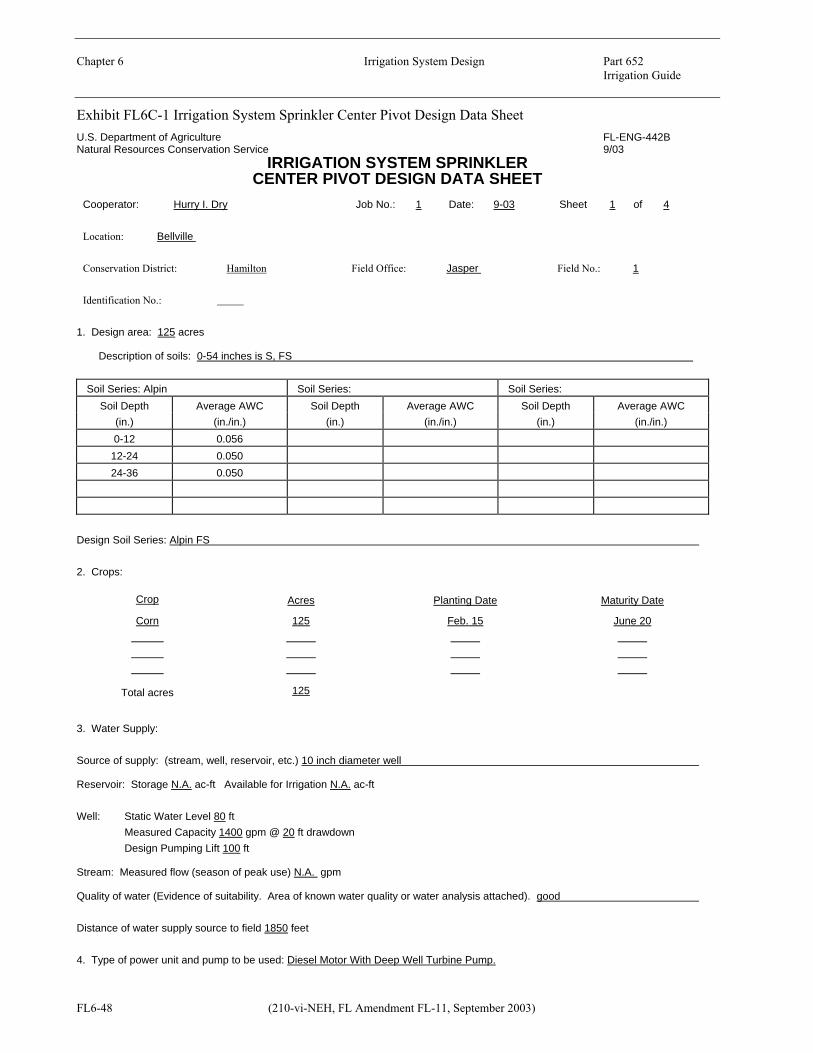
Chapter 6 Irrigation System Design Part 652 Irrigation Guide
Exhibit FL6C-1 Irrigation System Sprinkler Center Pivot Design Data Sheet U.S. Department of Agriculture FL-ENG-442B Natural Resources Conservation Service
FL6-48 (210-vi-NEH, FL Amendment FL-11, September 2003)
9/03 IRRIGATION SYSTEM SPRINKLER
CENTER PIVOT DESIGN DATA SHEET Cooperator: Hurry I. Dry Job No.: 1 Date: 9-03 Sheet 1 of 4
Location: Bellville
Conservation District: Hamilton Field Office: Jasper Field No.: 1
Identification No.:
1. Design area: 125 acres
Description of soils: 0-54 inches is S, FS
Soil Series: Alpin Soil Series: Soil Series: Soil Depth Average AWC Soil Depth Average AWC Soil Depth Average AWC
(in.) (in./in.) (in.) (in./in.) (in.) (in./in.) 0-12 0.056
12-24 0.050 24-36 0.050
Design Soil Series: Alpin FS
2. Crops:
Crop Acres Planting Date Maturity Date
Corn 125 Feb. 15 June 20
Total acres 125
3. Water Supply:
Source of supply: (stream, well, reservoir, etc.) 10 inch diameter well
Reservoir: Storage N.A. ac-ft Available for Irrigation N.A. ac-ft
Well: Static Water Level 80 ft Measured Capacity 1400 gpm @ 20 ft drawdown Design Pumping Lift 100 ft
Stream: Measured flow (season of peak use) N.A. gpm
Quality of water (Evidence of suitability. Area of known water quality or water analysis attached). good
Distance of water supply source to field 1850 feet
4. Type of power unit and pump to be used: Diesel Motor With Deep Well Turbine Pump.

Chapter 6 Irrigation System Design Part 652 Irrigation Guide
Exhibit FL6C-1 Irrigation System Sprinkler Center Pivot Design Data Sheet U.S. Department of Agriculture FL-ENG-442B Natural Resources Conservation Service 9/03
(210-vi-NEH, FL Amendment, FL-11, September 2003) FL6-49
Cooperator: Hurry I. Dry Job No.: 1 Date: 9-03 Sheet 2 of 4
5. Map of design area - Scale 1” = 660 feet. Sketch map on grid or attach photo or overlay.
. . . . . . . . . . . . . . . . . . . . . . . . . . . . .
. . . . . . . . . . . . . . . . . . . . . . . . . . . . .
. . . . . . . . . . . . . . . . . . . . . . . . . . . .
Existing 10” Dia Well; Required pump capacity is 1100 gpm @ 234.5 ft. TDH; Install 8” Check Valve, 2” Air Vent & 2” Pressure relief valve at Pump discharge. Install 2” Air Vent on all summits along mainline.
. . . . . . . . . . . . . . . . . . . . . . . . . . . .
. . . . . . . . . . . . . . . . . . . . . . . . . . . .
. . . . . . . . . . . . . . . . . . . . . . . . . . . .
. . . . . . . . . . . . . . . . . . . . . . . . . . . .
. . . . . . . . . . . . . . . . . . . . . . . . . . . .
. . . . . . . . . . . . . . . . . . . . . . . . . . . .
. . . . . . . . . . . . . . . . . . . . . . . . . . . .
. . . . . . . . . . . . . . . . . . . . . . . . . . . .
. . . . . . . . . . . . . . . . . . . . . . . . . . . .
. . . . . . . . . . . . . . . . . . . . . . . . . . . .
. . . . . . . . . . . . . . . . . . . . . . . . . . . .
. . . . . . . . . . . . . . . . . . . . . . . . . . . .
2,6
90
’
Thrust Block 10 sq. ft. Surface Area
Pivot Point Pressure = 38 PSI
NOTE: For location refer to Conservation Plan
. . . . . . . . . . . . . . . . . . . . . . . . . . . . 2,690’
Field Boundary
. . . . . . . . . . . . . . . . . . . . . . . . . . . . Irrigation System is to be in accordance with NRCS Conservation Practice Standard Code 442.
Map should show: Material-Mains a. Source of water Nominal PIP SDR Material Pressure Inside Total Minimum b. Elevation differences Pipe Size, or No. (PVC 1120 Rating Diam. Length, Depth of c. Row direction in. IPS etc.) psi in. feet Cover, in. d. System Layout 8 IPS 26 PVC 1120 160 7.961 1850 30 e. Plan of Operations f. Field Obstructions
(canals, trees, fences buildings, etc.)
g. North arrow

Chapter 6 Irrigation System Design Part 652 Irrigation Guide
Exhibit FL6C-1 Irrigation System Sprinkler Center Pivot Design Data Sheet U.S. Department of Agriculture FL-ENG-442B Natural Resources Conservation Service 9/03
FL6-50 (210-vi-NEH, FL Amendment FL-11, September 2003)
Cooperator: Hurry I. Dry Job No.: 1 Date: 9-03 Sheet 3 of 4
IRRIGATION UNIT NUMBER
6. Crop Information 1 2 3 4
Kind of Crop Corn
Acreage to be irrigated (acres)1/ 125.0
Rooting depth (in.) 36
Peak use rate (in./day) 0.23
7. Soil Information
Weighted AWC for rooting depth (in./in.) 0.052
Basic intake rate (in./hr.) 6.0
8. Design Procedure
AWC within root zone (in.) 1.87
% Depletion allowed prior to irrigation 50
Net water applied per irrigation (in.) 0.94
Water application efficiency (%) 85
Gross water applied per irrigation (in.) 1/ 1.11
Irrigation interval (days) 4.1
Irrigation period (days per irrigation) 1/ 4
Hours operating per day 1/ 18.0
QR = Quantity of water required (gpm) 1/ 873
QA 2/ = Quantity of water actual (gpm/unit) 1100.0
1/ QR = 453 x 125 acres x 1.11 in. gross application = 873 gpm 18 hrs. opr. per day x 4 days per irrigation 2/ Q Must be A > QR 9. Pivot Specifications (Provided by the Manufacturer): a. Pivot length 1314; Pivot pressure 38 psi
b. Spray or sprinkler
c. Gross application per revolution 1.11 in.
d. Nozzle gpm along last 100 ft. span 11.5 gpm @ 20 psi on spacing of 6.5 feet
e. Nozzle wetted diameter 45 feet
10. Checking maximum application rate: a. Time (hours) per revolution to apply gross application = 60 hrs. (Provided by the manufacturer).
b. Velocity (V) of end line = Outside circumference, ft = 8256= 138 ft/hr hours per revolution 60
c. Time of application, hrs = wetted diameter, ft = 45 = 0.33 hrs V,ft/hr 138
d. Average application rate, in/hr = gross application, in = 1.11 = 3.36 in/hr time of application, hrs 0.33
e. Max. application rate = 1.5 x application rate, in/hr = 1.5 x 3.36 in/hr = 5.0 in/hr

Chapter 6 Irrigation System Design Part 652 Irrigation Guide
Exhibit FL6C-1 Irrigation System Sprinkler Center Pivot Design Data Sheet U.S. Department of Agriculture FL-ENG-442B Natural Resources Conservation Service 9/03
(210-vi-NEH, FL Amendment, FL-11, September 2003) FL6-51
Cooperator: Hurry I. Dry Job No.: 1 Date: 9-03 Sheet 4 of 4
11. Determining Total Dynamic Head
Kind of Pipe Design Capacity Pipe Sizing IPS : PIP : Other Total Head
Loss, HL
(gpm) Diameter (in.)
Length (ft) Friction Loss (ft/100ft) (ft) (psi)
PVC-SDR26 1100 8 1850 1.74 32.2 13.9
Pressure at Pivot 87.8 38.0 Miscellaneous and Fitting Losses 3.0 1.3 Elevation Difference 3/ 11.5 5.0 Pump Discharge Pressure 134.5 58.2 Pumping Lift 100 43.3 Total Dynamic Head, TDH 234.5 101.5 3/ Difference in elevation of the centerline of the pump discharge and the elevation of the highest sprinkler (plus or minus).
12. Pump Requirements: 1100 gpm @ 101.5 psi or 234.5 ft of head TDH
Pump Discharge Pressure
13. Remarks: Use 160 psi rated SDR 26 PVC pipe
Design By: C. Planner Date: 9-03 Checked By: D. Conservationist Date: 9-03 Approved By: M. Engineer Date 9-03
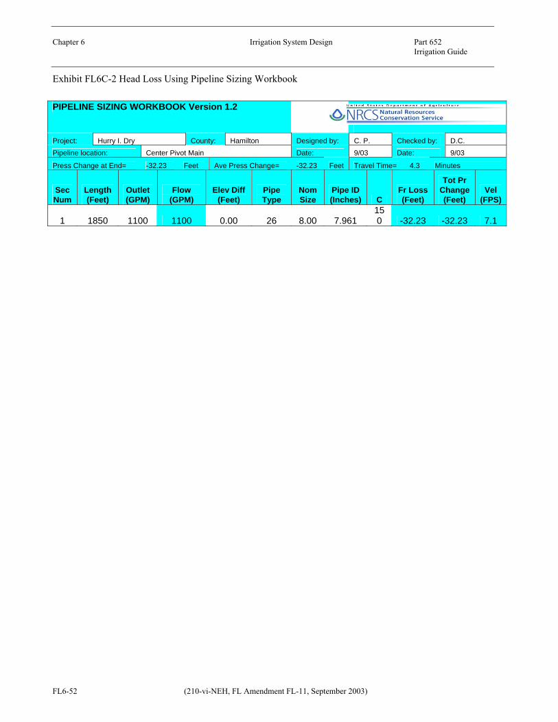
Chapter 6 Irrigation System Design Part 652 Irrigation Guide
Exhibit FL6C-2 Head Loss Using Pipeline Sizing Workbook
FL6-52 (210-vi-NEH, FL Amendment FL-11, September 2003)
PIPELINE SIZING WORKBOOK Version 1.2
Project: Hurry I. Dry County: Hamilton Designed by: C. P. Checked by: D.C. Pipeline location: Center Pivot Main Date: 9/03 Date: 9/03
Press Change at End= -32.23 Feet Ave Press Change= -32.23 Feet Travel Time= 4.3 Minutes
Sec Num
Length (Feet)
Outlet (GPM)
Flow (GPM)
Elev Diff (Feet)
Pipe Type
Nom Size
Pipe ID (Inches) C
Fr Loss (Feet)
Tot Pr Change (Feet)
Vel (FPS)
1 1850 1100 1100 0.00 26 8.00 7.961 150 -32.23 -32.23 7.1

Chapter 6 Irrigation System Design Part 652 Irrigation Guide
(210-vi-NEH, FL Amendment, FL-11, September 2003) FL6-53
FL652.0605d Traveling Gun Sprinkler Irrigation System GeneralThe example problem in this chapter is intended to illustrate the procedure to follow in the design of traveling gun irrigation systems. It is understood that one example cannot explain all design situations or alternatives to consider when designing traveling gun sprinkler irrigation systems. Design Criteria Minimum required design criteria for traveling gun sprinkler irrigation systems is contained in Florida NRCS conservation practice standard Irrigation System, Sprinkler, Code 442. Example ProblemThe following example problem is intended to cover the basic design steps to follow in the design of traveling gun sprinkler irrigation systems. A standard form (Exhibit FL6D-1) is used which is a useful tool in designing and recording data. Given: 1. Existing Nelson 200 gun, 24˚ trajectory, 1-½"
Ring Nozzle. 2. Crop & Acres: 40 acres watermelons 3. Soil: Alpin F. S. 4. Location: Jasper, Florida (Hamilton County) 5. Slope: Maximum 2% 6. Pump capability (existing): 400 gpm @370 ft TDH; 450 gpm @350 ft TDH; 500 gpm @320 ft TDH; rpm 2200 7. Crop Rows: North and South Solution: All item numbers mentioned in the step by step solution refer to the items on the standard form FL-ENG-442C "Irrigation System Sprinkler - Traveling Gun Design Data Sheet" in Exhibit FL6D-1. Step 1. Complete Items 1-4. These items provide an inventory of pertinent data of the site.
Step 2. Start map of field in Item 5. Make a drawing to scale of the field locating trees, buildings, wells and other physical features. This item will be completed after Item 10. Step 3. Complete Item 6. The moisture extraction root depths and the peak consumptive use rates are to be taken from this guide, Tables FL3-2 and FL4-7 respectively. Step 4. Complete Item 7. Obtain the soil series from a published soil survey report or an on-site investigation. The moisture holding capacity and intake rate are obtained from Florida Irrigation Guide (FIG), Chapter 2, Table 2-2. Step 5. Complete the following parts of Item 8.
a. Available water capacity (AWC) within the root zone is the root zone moisture extraction depth (36 inches) times the moisture holding capacity of the soil (0.052 in./in.). The AWC is = (36)(0.052) = 1.87 inches.
b. The percent depletion allowed prior to irrigation is selected to be 50%. Recommended values for percent depletion can be found in Chapter 3.
c. The net water applied per irrigation (in.) is the percent depletion allowed prior to irrigation (50%) times the water available within the root zone. The net water applied per irrigation is = (0.50)(1.87 in.) = 0.94 inch.
d. The water application efficiency is selected to be 65%. Florida NRCS conservation practice standard Irrigation System, Sprinkler Code 442 provides the maximum efficiencies to be used.
e. The gross water applied per irrigation (in.) is the net water applied (.94 in.) divided by the water application efficiency (65%). Gross water applied = 0.94 in. ÷ 0.65 = 1.45 inches.
f. The irrigation interval (days) is the net water applied (0.94 inches) divided by the crop peak consumptive use (0.19 in./day). Irrigation interval = 0.94 in ÷ 0.19 = 4.9 days, use 5.0 days.

Chapter 6 Irrigation System Design Part 652 Irrigation Guide
FL6-54 (210-vi-NEH, FL Amendment FL-11, September 2003)
g. The irrigation period to be used in the formula for determining the QR is the irrigation interval 5.0 days.
h. The hours operating per day were discussed with the owner who advised that he irrigated continuously until completed. Therefore, the 22 hours were agreed upon providing another 2 hours for moving the equipment.
i. Now determine the quantity of water required (QR ) in gpm for each crop using the formula as follows: QR = 453 Ad FH QR = 453 x 40 acs. x 1.45 in. gross applic. 22 hrs opr./day x 5 days/irrigation QR = 238.9 gpm
Step 6. Complete Item 9. a. Keeping in mind the capability of the pump
(see sheet FL6-51) and the minimum QR of 238.9 gpm, check the nozzle size, sprinkler gpm, and nozzle pressure using the Nelson Volume Gun performance tables. Since an existing pump is planned to be used, its pump curve must be considered in order to select a gpm and TDH that is within the pumps capability at as high an operating efficiency as possible. Now for this area, from past experiences the TDH for this size system should compute to be about 320 to 340 feet. If experience is lacking, one must select a Q greater than or equal to QR and then complete Item 11 until the gpm and TDH are compatible with the pumps performance capability. Based on the information given on the existing pump’s operation, the pump should to be able to deliver about 460 gpm at 340 feet TDH. Using the Nelson Volume Gun Performance Tables with a nozzle size of 1- ½ inches, a capacity of 460 gpm at 85 psi nozzle pressure with a wetted diameter of 418 feet was selected.
b. Determine the lane spacing using
approximately 60-65% of the wetted diameter of the sprinkler. The total length of the field is 2,660 feet. Realizing that the
PVC pipe comes in 20 feet lengths, it is desirable to select a spacing that does not require field cutting of the pipe. The spacing 260 ft between risers was tentatively selected which is 62% of the wetted diameter. Now, in order to properly irrigate the ends of the field, the riser needs to be approximately 75% of the wetted radius (418 ÷ 2) away from the field boundary (i.e., 0.75 x 209 ft) or 157 feet. Now determine the distance actually available by dividing the distance 2,660 ft by 260 ft. = 10.23 spaces. Take 1.23 spaces x 260 ft/space = 320 ft. and place half of this (160 Ft.) distance at each end of the field between the riser and field boundary. The 160 feet is adequate.
c. The application rate is computed using the
following formula:
Application rate(in/hr) = 110 x sprinkler gpm
Area of wetted circle, sq ft
= 110 x 460 gpm 137,228 sq ft = 0.37 in./hr
d. The travel speed is computed by the
following formula:
Travel Speed(ft/min) = 1.605 x sprinkler gpm lane spacing(ft) x gross water applied(in) = 1.605 x 460 = 1.96 ft/min
260 x 1.45 e. Time per 660 ft. run (hrs)
= 660 ft x 1 hr 1.96 ft/min 60 min
= 5.61 hours Step 7. Complete Item 10. Fill in a – d based on previous design decisions made during Item 9. Step 8. Go back to Item 5 and make a scaled plan layout of the system. Show locations of pump,

Chapter 6 Irrigation System Design Part 652 Irrigation Guide
(210-vi-NEH, FL Amendment, FL-11, September 2003) FL6-55
risers, bends, etc. Pipe sizes etc., will be added later. Step 9. Size the mainline and determine the Total Dynamic Head required for the pump: a. Complete Item 11 for sizing the pipe. Use a 6-
inch diameter PVC, SDR 26, 160 psi rated IPS pipe. A length of 1,690 ft was determined from the layout. The friction head loss is 1.25 ft/100 ft and was interpolated from the friction head loss tables in Chapter 16. The total head loss for the 6-inch PVC is 1.25 ft/100 ft x 1,690 ft = 21.1 ft. An alternative to compute the friction loss is to use the Pipeline Sizing Workbook (Excel spreadsheet program) as shown in Exhibit FL6D-2.
b. Use 660 ft of 4-½ inch flexible hose the
irrigator has on hand. This is within the guide for flexible hose selection, as shown in Table FL6D-1. The friction loss taken from Figure FL6D-1 is 1.7 psi/100 ft or 3.93 ft/100 ft. Total head loss for the hose is 660 ft x 3.93 ft/100 ft = 25.9 ft.
c. Enter the sprinkler pressure at the nozzle,
miscellaneous losses and elevation differences between the well and the nozzle when located on the high point in the field.
d. The sum of a, b, and c gives a pump discharge
pressure required of 256.4 feet of head or 111.0 psi.
e. The total dynamic head is the pumping lift plus
the pump discharge pressure. 256.4 ft + 60 ft = 316.4 ft = 137.0 psi.
f. The pump requirement of 460 gpm at 316.4
feet of head is within the capability of the pump.
Step 10. Complete the engineering plans. The size and location of the pipe, check valves, air vents, pressure relief valve, risers, thrust blocks, etc., should be shown on the plans in Item 5. See sheet 2 of 4 of Exhibit FL6D-1. If the system is too complex to show the detail in Item 5, an irrigation plan map should be prepared in sufficient detail to describe the system. Item 5 should then reference this set of drawings. The
construction specifications should be attached to the drawings. Layout ConsiderationsItems that must be considered are as follows: a. Plant spacing and/or row direction so that
travel lanes can be located properly. b. Location of obstacles and safety hazards. c. Whenever possible, place the risers a full hose
length, along the travel path, away from the edge of the field. This greatly facilitates laying out the hose and reeling it back.
d. Soil limitations such as surface texture may
necessitate a part circle volume gun so that the area is not irrigated in front of the gun as it moves, providing a dry footing.
e. Topography may dictate the lane direction to
prevent misalignment of the traveler while in operation.
Construction Requirements The following is a list of construction items that should be checked to be assured of a quality installation: a. The depth of cover over the buried mainline
must be adequate for protection from vehicular traffic and the farming operation.
b. Thrust block dimensions and location to
prevent pipe joint separation. c. Location and size of air vents and pressure
relief valves. d. Size and proper direction of check valves. e. Riser material, size, number and location. f. Verify the pipe requirements such as SDR
number, pressure rating, ASTM designation, PVC material, pipe diameter and if PIP or IPS sized pipe.
g. Verify pump, motor and well size. Check nozzle pressure.
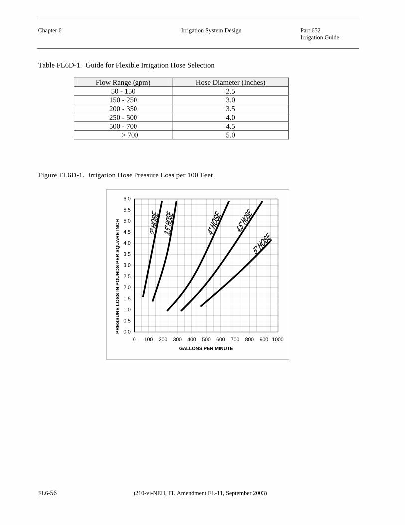
Chapter 6 Irrigation System Design Part 652 Irrigation Guide
Table FL6D-1. Guide for Flexible Irrigation Hose Selection
Flow Range (gpm) Hose Diameter (Inches) 50 - 150 2.5
150 - 250 3.0 200 - 350 3.5 250 - 500 4.0 500 - 700 4.5
> 700 5.0 Figure FL6D-1. Irrigation Hose Pressure Loss per 100 Feet
0.0
0.5
1.0
1.5
2.0
2.5
3.0
3.5
4.0
4.5
5.0
5.5
6.0
0 100 200 300 400 500 600 700 800 900 1000
GALLONS PER MINUTE
PRES
SUR
E LO
SS IN
PO
UN
DS
PER
SQ
UA
RE
INC
H
FL6-56 (210-vi-NEH, FL Amendment FL-11, September 2003)

Chapter 6 Irrigation System Design Part 652 Irrigation Guide
Exhibit FL6D-1 Irrigation System Sprinkler Traveling Gun Design Data Sheet U.S. Department of Agriculture FL-ENG-442C Natural Resources Conservation Service
(210-vi-NEH, FL Amendment FL-11, September 2003) FL6-57
9/03 IRRIGATION SYSTEM SPRINKLER
TRAVELING GUN DESIGN DATA SHEET Cooperator: T.O. Dry, Jr. Job No.: 1 Date: 9-03 Sheet 1 of 4
Location: T1N,R12E,514 S.W. Jasper& S of SR6
Conservation District: Hamilton Field Office: Jasper Field No.: 1
Identification No.:
1. Design area: 40 acres
Description of soils: 0-99 Inches is FS
Soil Series:Alpin Soil Series: Soil Series: Soil Depth Average AWC Soil Depth Average AWC Soil Depth Average AWC
(in.) (in./in.) (in.) (in./in.) (in.) (in./in.) 0-12 0.056 12-24 0.050 24-36 0.050 36-48 0.050 48-60 0.063
Design Soil Series: Alpin
2. Crops:
Crop Acres Planting Date Maturity Date
Watermelons 40 March 15 June 15
Total acres 40
3. Water Supply:
Source of supply: (stream, well, reservoir, etc.) 10" diameter well Reservoir: Storage N.A. ac-ft Available for Irrigation N.A. ac-ft
Well: Static Water Level 48 ft Measured Capacity 600 gpm @ 12 ft drawdown Design Pumping Lift 60 ft
Stream: Measured flow (season of peak use) N.A. gpm Quality of water (Evidence of suitability. Area of known water quality or water analysis attached). good
Distance of water supply source to field feet
4. Type of power unit and pump to be used: LP Gas, Chrysler Industrial, 8 Cylinder. Pump is Berkeley Model 804H, 10 Stage, Serial Number 2313H

Chapter 6 Irrigation System Design Part 652 Irrigation Guide
Exhibit FL6D-1 Irrigation System Sprinkler Traveling Gun Design Data Sheet U.S. Department of Agriculture FL-ENG-442C Natural Resources Conservation Service 9/03
FL6-58 (210-vi-NEH, FL Amendment FL-11, September 2003)
Cooperator: T.O. Dry, Jr. Job No.: 1 Date: 9-03 Sheet 2 of 4
5. Map of design area - Scale 1” = 660. feet. Sketch map on grid or attach photo or overlay. . . . . . . . . . . . . . . . . . . . . . . . . . . . . . . . .
. . . . . . . . . . . . . . . . . . . . . . . . . . . . . . . .
. . . . . . . . . . . . . . . . . . . . . . . . . . . . . . . .
. . . . . . . . . . . . . . . . . . . . . . . . . . . . . . . .
. . . . . . . . . . . . . . . . . . . . . . . . . . . . . . . .
. . . . . . . . . . . . . . . . . . . . . . . . . . . . . . . .
. . . . . . . . . . . . . . . . . . . . . . . . . . . . . . . .
. . . . . . . . . . . . . . . . . . . . . . . . . . . . . . . .
. . . . . . . . . . . . . . . . . . . . . . . . . . . . . . . .
. . . . . . . . . . . . . . . . . . . . . . . . . . . . . . . .
. . . . . . . . . . . . . . . . . . . . . . . . . . . . . . . .
. . . . . . . . . . . . . . . . . . . . . . . . . . . . . . . .
. . . . . . . . . . . . . . . . . . . . . . . . . . . . . . . .
. . . . . . . . . . . . . . . . . . . . . . . . . . . . . . . .
. . . . . . . . . . . . . . . . . . . . . . . . . . . . . . . .
. . . . . . . . . . . . . . . . . . . . . . . . . . . . . . . .
. . . . . . . . . . . . . . . . . . . . . . . . . . . . . . . .
. . . . . . . . . . . . . . . . . . . . . . . . . . . . . . . .
1690’ 650’
Edge of Field
160’
Specifications 1. Pipe- 6”PVC, 160 PSI rated 2. Pipe cover- 30” minimum 3. Risers- 6”x42” Epoxy Coated Steel 4. 2” Air Vents on all summits and as shown on the drawing 5. Thrust blocks (6 sq. ft. surface area ) - locate as shown below. 6. 6” Downspout 7. System to be in accordance with Florida NRCS Conservation
Practice Standard Code 442
Risers on 260 ft. spacing
Thru
st B
lock
2
” A
ir V
ent
to R
iser
Thrust Block
2” Air Vent to Riser
6” o PVC Pipe
Well; Install 6” o Check Valve, 2” Air Vent and 2” Pressure Relief Valve
Thrust Block
N
Map should show: Material-Mains and Manifolds a. Source of water Nominal PIP SDR Material Pressure Inside Total Minimum b. Elevation differences Pipe Size, or No. (PVC 1120 Rating Diam. Length, Depth of c. Row direction in. IPS etc.) psi in. feet Cover, in. d. Trickle system layout 6 IPS 26 1120 160 6.115 1690 30 e. Plan of Operations f. Field Obstructions
(canals, trees, fences buildings, etc.)
g. North arrow

Chapter 6 Irrigation System Design Part 652 Irrigation Guide
Exhibit FL6D-1 Irrigation System Sprinkler Traveling Gun Design Data Sheet U.S. Department of Agriculture FL-ENG-442C Natural Resources Conservation Service 9/03
(210-vi-NEH, FL Amendment, FL-11, September 2003) FL6-59
Cooperator: T.O. Dry, Jr. Job No.: 1 Date: 9-03 Sheet 3 of 4
CROP NUMBER 6. Crop Information 1 2 3 4 Kind of Crop Watermelons Acreage to be irrigated (acres)1/ 40 Rooting depth (in.) 36 Peak use rate (in./day) 0.19 7. Soil Information Weighted AWC for rooting depth (in./in.) 0.052 Basic intake rate (in./hr.) 3 8. Design Procedure AWC within root zone (in.) 1.87 Depletion allowed prior to irrigation (%) 50 Net water applied per irrigation (in.) 0.94 Water application efficiency (%) 65 Gross water applied per irrigation (in.)1/ 1.45 Irrigation interval (days) 4.9 Irrigation period (days per irrigation) 1/ 5.0 Hours operating per day1/ 22 QR
1/ = Quantity of water required (gpm) 239 9. Irrigation Unit Design QA
2/ = Quantity of water actual (gpm) 460 Application rate (in./hr) 3/ 0.37 Lane Spacing, ft Travel Speed (ft/min) 4/ Lane Spacing, 260 ft 1.96 Lane Spacing, ft Time per 660 ft run (hrs) 5/ Lane Spacing, 260 ft 5.61
10. Sprinkler Specifications: a. Lane Spacing 260 ft
b. Nozzle Size 1.5 in., Wetted Diam. 418 ft Capacity 460 gpm @ 85.0 psi Make and model of sprinkler Existing Nelson 200 gun, 24° Trajectory
c. No. of sprinklers operating simultaneously 1
d. Total design capacity all sprinklers 460 gpm 1/ QR = 453 x 40 acres x 1.45 inches gross application = 239 gpm 22 hours opr. per day x 5.0 days per irrigation
2/ QA must be > QR
3/ Application rate, in./hr = 110.0 x sprinkler gpm (MUST BE < BASIC INTAKE RATE) Area of wetted circle, sq. ft.
4/ Travel Speed, ft/min = 1.605 x sprinkler gpm Lane Spacing, ft x gross water applied, in.
5/ Time per run, hrs. = Length of run, ft. Travel Speed, ft/min. x 60

Chapter 6 Irrigation System Design Part 652 Irrigation Guide
Exhibit FL6D-1 Irrigation System Sprinkler Traveling Gun Design Data Sheet U.S. Department of Agriculture FL-ENG-442C Natural Resources Conservation Service 9/03
FL6-60 (210-vi-NEH, FL Amendment, FL-11, September 2003)
Cooperator: T.O. Dry, Jr. Job No.: 1 Date: 9-03 Sheet 4 of 4
11. Determining Total Dynamic Head: Total main line length 2340 ft.
IPS PIP PIPE SIZING HOSE SIZING Total Head Loss
Kind of Pipe/Hose
Pipe Size (in.)
Design Capacity
(gpm)
Length (ft)
Friction Head Loss (ft/100ft)
Length (ft)
Friction Head Loss (ft/100ft)
(ft) (psi)
PVC 6 460 1690 1.25 21.1 9.1
Hose 4.5 460 660 3.93 25.9 11.2
Sprinkler pressure at nozzle 196.4 85
Misc. & fitting losses 3.0 1.3
Elevation difference 6/ 10.0 4.3
Pump discharge pressure 256.4 111.0 Pump lift 60 26.0
Total Dynamic Head, TDH 316.4 137.0 6/ Difference in elevation of the centerline of the pump discharge and the elevation of the highest sprinkler (plus or
minus).
12. Pump Requirements: 460 gpm @ 137.0 psi or 316.4 ft or head TDH
Pump Discharge Pressure
13. Remarks Existing Pump Capability; 400 gpm @370 ft TDH; 450 gpm @350 ft TDH; 500 gpm @320 ft TDH;
RPM=2200.
Design By: A.C. Lee Date: 9-03 Checked By: E.O.C. Date: 9-03 Approved By: E. O. Cooper Date: 9-03

Chapter 6 Irrigation System Design Part 652 Irrigation Guide
Exhibit FL6D-2 Head Loss Using Pipeline Sizing Workbook
(210-vi-NEH, FL Amendment, FL-11, September 2003) FL6-61
PIPELINE SIZING WORKBOOK Version 1.2
Project: T. O. Dry, Jr. County: Hamilton Designed by: A. L. Checked by: E.C. Pipeline location: Traveling Gun Main Date: 9/03 Date: 9/03
Press Change at End= -21.15 Feet Ave Press Change= -21.15 Feet Travel Time= 5.6 Minutes
Sec Num
Length (Feet)
Outlet (GPM)
Flow (GPM)
Elev Diff (Feet)
Pipe Type
Nom Size
Pipe ID (Inches) C
Fr Loss (Feet)
Tot Pr Change (Feet)
Vel (FPS)
1 1690 460 460 0.00 26 6.00 6.115 150 -21.15 -21.15 5.0

Chapter 6 Irrigation System Design Part 652 Irrigation Guide
FL6-62 (210-vi-NEH, FL Amendment FL-11, September 2003)
THIS PAGE INTENTIONALLY LEFT BLANK

Chapter 6 Irrigation System Design Part 652
Irrigation Guide
(210-vi-NEH, FL Amendment, FL-12, May 2006) FL6-63
FL652.0605e Subsurface – Flow Through Irrigation System
General The example problem in this chapter is intended to illustrate the procedure to follow in the design of a "flow through" or semi-enclosed, subsurface irrigation system. It is understood that one example problem cannot illustrate all design situations or alternatives to consider when designing this type of system. Design Criteria Design criteria for subsurface irrigation systems are contained in the Florida NRCS conservation practice standard, Irrigation System, Surface and Subsurface, Code 443. All subsurface irrigation systems must be designed in accordance with applicable requirements contained in Code 443. Example Problem The following example problem is intended to cover the basic design steps to follow in the design of a flow-through subsurface irrigation system for small vegetables. Given: 1. Location: Sebring, Highlands County, FL
(Climatic Zone 4) 2. Size of field: 23 acres 3. Slope of field: Essentially level 4. Water furrow spacing: 60 feet. 5. Crop: Small vegetables to be planted in
January. 6. Soils: Predominantly Immokalee fine sand
with a slightly impervious zone at depths from 35 inches to 54 inches.
7. Existing well, pump and power unit: 6 inch diameter well, Smith Pump Co., Model Number 4ZQ-5, Serial Number 6347N centrifugal pump, 6 inch diameter impeller; 3 horse power, 1760 R.P.M. electric motor. Static water level is 10 ft below ground surface. Well capacity is 300 gpm at 5 ft drawdown.
Solution: Step 1. Determine adequacy of furrow spacing for subsurface water removal and check adequacy of outlets for drainage. This will not be checked in this example but should be checked to insure adequate drainage. Step 2. Prepare sketch of area to be irrigated showing location of well, pipeline, length of furrows, etc. See Exhibit FL6E-1. Step 3. Determine water requirements. From Chapter 4, Table FL4-7, the peak consumptive use rate is 0.18 in./day. Assuming a water application efficiency of 50 percent the water requirement is: = 0.18 ac-in. × 1 × 452.57 gpm × 1 day day 0.50 efficiency 1 ac-in./hr 24 hrs = 6.78 gpm/ac, use 7.0 gpm/ac Total water requirement = 23 ac x 7 gpm/ac = 161 gpm Referring to Exhibit FL6E-1, there are 10 furrows 635 ft long, 12 furrows 380 ft long and 6 furrows 970 ft long. Consider the 635 ft long furrows: Acres/bed = 635 ft × 60 ft = 0.87 43,560 sq ft/ac gpm required = 7 gpm/ac × 0.87 ac/furrow = 6.12 gpm/furrow Consider the 380 ft long furrows: Acres/bed = 380 ft × 60 ft = 0.52 43,560 sq ft/ac gpm required = 7 gpm/ac × 0.52 ac/furrow = 3.64 gpm/furrow Consider the 970 ft long furrows: Acres/bed = 970 ft × 60 ft = 1.34 43,560 sq ft/ac gpm required = 7 gpm/ac × 1.34 ac/furrow = 9.38 gpm/furrow

Chapter 6 Irrigation System Design Part 652 Irrigation Guide
FL6-64 (210-vi-NEH, FL Amendment, FL-12, May 2006)
Check: (6.12 gpm/furrow × 10 furrows) + (3.64 gpm/furrow × 12 furrows) + (9.38 gpm/furrow × 6 furrows) = 161 gpm ok Step 4. Size pipeline. The pipe sizes for the distribution system are selected by using the trial and error method. The corresponding friction head losses (Hf) are determined for the selected pipe sizes. Other head losses (minor) that occur at entrances, exits, elbows, tees, reducers and valves can be determined and added to the head losses in
the pipeline. The pipe selections will be satisfactory if the total friction head loss does not exceed the total head produced by the pump. Pipe friction losses for this example are taken from Table FL16-6, Friction Head Loss in Plastic (PVC or ABS) Irrigation Pipelines – SDR 21 IPS. The total friction loss is computed for the pipeline south of the well and for the pipeline north of the well in order to determine the maximum friction head loss. The following tabular form of working through pipeline friction losses is convenient.
For the portion of the field lying to the south of the well, refer to Exhibit FL6E-1.
Direction Length
ft
Cum. Length
ft
Req’d Q
gpm
Pipe Size Selection
inches
Friction Head Loss
ft/ft
Friction Head Loss
ft
Cum. Total Hf
ft Pump to Main,
30 30 161 5 0.0045 0.13 0.13
South 7 37 106 4 0.0059 0.04 0.17 60 97 100 4 0.0052 0.31 0.48 60 157 96 4 0.0049 0.29 0.77 60 217 93 4 0.0045 0.27 1.04 60 277 89 4 0.0041 0.25 1.29 60 337 86 4 0.0040 0.24 1.53 60 397 82 4 0.0035 0.21 1.74 60 457 78 3 0.0109 0.65 2.39 60 517 75 3 0.0106 0.64 3.03 60 577 71 3 0.0095 0.57 3.60 60 637 68 3 0.0085 0.51 4.11 60 697 64 3 0.0078 0.47 4.58 60 757 60 3 0.0069 0.41 4.99 60 817 57 3 0.0063 0.38 5.37 60 877 47 3 0.0044 0.26 5.63 60 937 38 3 0.0029 0.17 5.80 60 997 29 2 0.0120 0.72 6.52 60 1057 19 2 0.0055 0.33 6.85 60 1117 9 2 0.0014 0.08 6.94=Total
Head Losses through fittings and outlet pipes south of the well: 1. Elbows, 2 ea. 45º, 5 inch diameter,
he = 2 × K45 × v2 2g
v = 0.408 Q = 0.408 x 161gpm = 2.63 ft/sec d2 (5 in)2
(Refer to Table FL16-3 for K values.) K45 = 0.4 he = 2 × 0.4 × 0.11 = 0.1 ft

Chapter 6 Irrigation System Design Part 652
Irrigation Guide
(210-vi-NEH, FL Amendment, FL-12, May 2006) FL6-65
2. 4" × 4" × 5" Tee = K × v2 2g
v = 0.408 Q = 0.408 x 161 gpm = 2.63 ft/sec d2 (5 in)2
(Refer to Table FL16-3 for K values.) Ktee = 1.50 he = 1.50 × 0.11= 0.2 ft
3. Entrance loss into outlet pipes, use he = 1.0 ft
4. Valve in outlet pipe – assume to be a 3/4" angle valve flowing at 10 gpm
He = Kvalve × v2 2g
v = 0.408 Q = 0.408 x 10 gpm = 7.25 ft/sec
d2 (0.75 in)2
(Refer to Table FL16-3 for K values.) Kvalve = 5.0 he = 5.0 × 0.82= 4.1 ft
5. Other losses (disregard) = 0
6. Total losses in fittings and outlet pipes = (0.1 ft + 0.2 ft + 1.0 ft + 4.1 ft) = 5.4 ft
Total losses in pipeline to the south + 6.9 ft Total losses in pipeline and fittings = 12.3 ft
For the portion of the field lying to the north of the well, refer to Figure FL6E-1. Direction Length
ft
Cum. Length
ft
Req’d Q
gpm
Pipe Size Selection
inches
Friction Head Loss
ft/ft
Friction Head Loss
ft
Cum. Total Hf
ft Pump to Main,
30 30 161 5 0.0045 0.13 0.13
North 53 83 55 4 0.0017 0.09 0.22 60 143 49 4 0.0014 0.08 0.30 60 203 43 3 0.0037 0.22 0.52 60 263 37 3 0.0028 0.17 0.69 60 323 31 3 0.0020 0.12 0.81 60 383 24 2 0.0084 0.50 1.31 60 443 18 2 0.0050 0.30 1.61 60 503 12 2 0.0024 0.14 1.75 60 563 6 2 0.0006 0.04 1.8=Total
Head losses through fittings and outlet pipes north of the well: 1. Elbows, 2 each 45°, 5-inch diameter,
he = 2 × K45 × v2 2g
v = 0.408 Q = 0.408 x 161 gpm = 2.63 ft/sec d2 (5 in)2
(Refer to Table FL16-3 for K values.) K45 = 0.4
he = 2 × 0.4 × 0.11 = 0.1 ft
2. 4" × 4" × 5" Tee = K × v2 2g
v = 0.408 Q = 0.408 x 161 gpm = 2.63 ft/sec d2 (5 in)2
(Refer to Table FL16-3 for K values.) Ktee = 1.50
he = 1.50 × 0.11= 0.2 ft
3. Entrance loss into outlet pipes, use he = 1.0 ft
4. Valve, 3/4 in. angle valve flowing at 6 gpm he = Kvalve × v2 2g v = 0.408 Q = 0.408 x 6 gpm = 4.3 ft/sec
d2 (0.75 in)2
(Refer to Table FL16-3 for K values.) Kvalve = 5.0

Chapter 6 Irrigation System Design Part 652 Irrigation Guide
FL6-66 (210-vi-NEH, FL Amendment, FL-12, May 2006)
he = 5.0 × 0.30 = 1.5 ft 5. Other losses (disregard) = 0
6. Total losses in fittings and outlet pipes = (0.1 ft + 0.2 ft + 1.0 ft + 1.5 ft) = 2.8 ft
Total losses in pipeline to the north + 1.8 ft Total losses in pipeline and fittings = 4.6 ft
Step 5. Determine head loss in the pipeline south of the well is 12.3 ft which is greater than the friction loss north of the well of 4.6 ft. With a
pumping lift of 15 ft, the pump requirements are 161 gpm at 27.3 ft TDH (12.3 ft + 15.0 ft). The amount of head loss for both the north and south pipelines indicates that the pipe size selections could be modified to smaller sizes. With reference to the pump rating curves shown in Figure FL6E-1, 161 gallons per minute can be produced at approximately 30 ft TDH with the expenditure of about 2 horsepower. The design of 161 gpm @ 27.3 ft TDH is within the capabilities of the pump.

Chapter 6 Irrigation System Design Part 652
Irrigation Guide
(210-vi-NEH, FL Amendment, FL-12, May 2006) FL6-67
Figure FL6E-1. Pump Rating Curves

Chapter 6 Irrigation System Design Part 652 Irrigation Guide
FL6-68 (210-vi-NEH, FL Amendment, FL-12, May 2006)
THIS PAGE INTENTIONALLY LEFT BLANK

Chapter 6 Irrigation System Design Part 652 Irrigation Guide
(210-vi-NEH, FL Amendment, FL-12, May 2006) FL6 - 69
Step 6. Complete the plans. See Exhibit FL6E-1 for a sample plan.

Chapter 6 Irrigation System Design Part 652
Irrigation Guide
THIS PAGE INTENTIONALLY LEFT BLANK
FL6-70 (210-vi-NEH, FL Amendment, FL-12, May 2006)

Chapter 6 Irrigation System Design Part 652
Irrigation Guide
(210-vi-NEH, FL Amendment, FL-12, May 2006) FL6-71
FL652.0605f Subsurface – Underground Conduit
General The example problem in this chapter is intended to illustrate the procedure to follow in the design of a subsurface irrigation system using underground conduit. It is understood that one example problem cannot illustrate all design situations or alternatives to consider when designing this type of system. Design Criteria Design criteria for subsurface irrigation systems are contained in the Florida NRCS conservation practice standard, Irrigation System, Surface and Subsurface, Code 443. All subsurface irrigation systems must be designed in accordance with applicable requirements contained in Code 443. Design Procedures The design procedures for subsurface irrigation, underground conduit, are similar to that for subsurface, open ditch systems, except for the following variances: 1. Depth of tile - minimum depth of 24 inches
except in areas with vehicular traffic. See Florida NRCS conservation practice standard, Subsurface Drain, Code 606. Maximum depths are dependant on crop needs and soil characteristics.
Greater tile depth may permit wider tile spacing.
2. System layout - tubing is installed at or near a flat grade at a uniform depth which locates laterals parallel to land surface contours. See Relief Line Spacing Table FL6F-1.
3. Diameter of tubing is determined by using the Drain Chart - Exhibit FL6F-2 or Manning's equation with "n" = 0.015. For tile grade, use desired water surface gradient.
4. Size mainline to carry the maximum flow requirements: irrigation or drainage.
5. Locate structures to get the desired water table elevations.
Example Problem The following example problem is intended to cover the basic design steps to follow in the design of subsurface underground conduit irrigation systems. Given: Owner desires a 20-acre field to be irrigated by underground conduit. The crops planned are small vegetables to be planted in January. Water supply will be from an existing 4-inch well with a capacity of 150 gpm. Location is near Sebring, FL (Climatic Zone 4). Solution Step 1. Gather field data. Take sufficient survey notes to determine the topography of the field, location and elevations of outlet ditches, location of water supply and other pertinent information. Make a drawing showing the above information. See Exhibit FL6F-1, sheet 1 of 2. Step 2. Determine soils information. Soils were checked and found to be Immokolee fine sand with a slightly impervious zone at depths ranging from 35 inches to 54 inches. Step 3. Obtain crop information. The planned crop is small vegetables. From Chapter 4, Table FL4-7, the peak consumptive use rate is 0.18 in./day. The rooting depth from Chapter 3, Table FL3-2 is 18 inches. Step 4. Determine design requirements. a. For irrigation, the system must be able to replace the maximum peak consumptive use. Assuming an application efficiency of 50 percent the irrigation requirement per acre is Q, gpm = 0.18 ac-in. × 1 × day 0.50 eff 452.57 gpm × 1 day = 6.78 gpm or 0.015 cfs 1 ac-in./hr 24 hr Existing systems indicate that 7.0 gpm/ac is sufficient to uniformly raise the water table. Use 7 gpm/acre. b. For drainage, a removal rate of 4 inches in 24 hours is to be used. Three inches are to be removed by surface facilities and 1 inch through subsurface drains.

Chapter 6 Irrigation System Design Part 652 Irrigation Guide
FL6-72 (210-vi-NEH, FL Amendment, FL-12, May 2006)
The drainage requirement Q in cfs for drainage is Q = 4 in. × 20 ac × 0.042 cfs = 3.36 cfs 24 hr 1 ac-in./24 hr Step 5. Determine outlet capacity. The outlet channel must have the capacity to remove the 3.36 cfs plus discharge from any other contributing area at the desired hydraulic gradeline. Refer to Florida NRCS conservation practice standard, Surface Drainage, Main or Lateral, Code 608. Step 6. Determine adequacy of surface drainage facilities. Adequate surface drainage should be available to remove the excess water. Refer to Florida NRCS conservation practice standard, Surface Drainage, Field Ditch, Code 607. Make modifications as necessary to provide adequate drainage. Step 7. Determine subsurface drainage requirements. a. Determine drain depth. From the NRCS Soil Data Mart website, http://soildatamart.nrcs.usda.gov/, and confirmed by site investigation, tile depth of 30 inches will be at and above the slightly impervious zone. Use tile depth of 30 inches to top of tile for laterals. b. Determine drain lateral spacing. From the NRCS Soil Data Mart website, http://soildatamart.nrcs.usda.gov/, permeability ranges from 6.0 in./hr to 20 in./hr in the soil profile to be drained. For this example, the barrier depth is assumed to be a 42 inches and permeability to be 6.0 in./hr. From Table FL6F-1, Relief Lane Spacing Tables, sheet 5 of 6, using a drainage coefficient of 1 inch/day, root zone of 18 inches and a depth of 30 inches to the drain, the spacing required is 58.8 feet. Use 60 feet. In lieu of using Table FL6F-1, the ellipse equation for determining spacing may be used. S = ((4P (b2 – a2))/Qd)1/2
Where: S = spacing of drains (feet) P = permeability (inches per hour) b = Depth from drawdown curve to barrier (feet) d = Depth of drain (feet) a = Depth from drain to barrier (feet) Qd = Required removal rate (in./hr)
Then S = ((4(6)(32 - 22))/0.042)1/2 = 53.45 ft Use 60 ft
c. Determine diameter of laterals. Scale from the drawing, Exhibit FL6F-1, sheet 1 of 2, the length of the laterals. The laterals are drawn on the drawing based on the spacing of 60 feet (determined in 7.b.) and on a grade parallel to field surface contours. Area served per lateral = 60 ft × 467 ft length 43,560 ft2/ac
= 0.64 acre Q required = 0.64 ac × 1 in. × 0.042 cfs 24 hr 1 ac-in./24 hr = 0.027 cfs/lateral The effective hydraulic grade line of the lateral is based on the water surface at the upstream end of the lateral being at the root zone depth of 18 inches and at the top of the lateral at the main line. The head on the lateral is: 30 inches - 18 inches = 12 inches = 1.0 ft The gradient is 1 ft ÷ 467 ft = 0.0021 ft/ft or 0.21 ft/100 feet From Drain Chart, Exhibit FL6F-2, at a grade of 0.21 ft/100 feet and a Q of 0.027 cfs, a minimum drain size of 4 inches is satisfactory. In lieu of Exhibit FL6F-2, the following equation can be used: di = (1630Qn/ S1/2)3/8
Where di = inside diameter in inches
n = Manning's coefficient of roughness Q = required discharge (cfs) S = loss of head in foot per foot of conduit
Then di = (1630×0.027×0.015)/(0.002)1/2)3/8
= 2.74 inches Use 4-inch diameter minimum.
d. Design main line. Determine location of the main line and draw main line on plan sheet. Plot and draw main on profile sheet to connect lateral location on main line. See Exhibit FL6F-1, sheet 1 of 2.

Chapter 6 Irrigation System Design Part 652
Irrigation Guide
(210-vi-NEH, FL Amendment, FL-12, May 2006) FL6-73
Gradient of main is calculated to be 0.182 ft/100 ft (with no submerged flow at outlet). Determine the required diameter of the main line at any station by first determining the required Q and the slope of the main at a station. Then enter the slope and required Q on the Drain Chart, Exhibit FL6F-2 to obtain the required diameter. See Exhibit FL6F-1, sheet 2 of 2, for summary of calculations at the outlet, 10-inch diameter is required. At the mid-point of the field where 10 acres are drained, an 8-inch diameter is adequate. Step 8. Determine subsurface irrigation requirements. Locate structures on main profile. a. Determine hydraulic gradient to be 1 ft in 700 ft or 0.14 ft/100 feet (when water at the structures is at ground elevation and water table at remote end of lateral is 1 ft. below ground surface). The 700 feet include 450 ft of lateral B-6 and 250 ft of the main to S-4 (typical lateral and main section). See Exhibit FL6F-1, sheet 1 of 2. b. Size determination of main. At the high end of the main where flow for 20 acres is required, Q = 7.0 gpm/ac × 20 ac × 1 cfs = 0.31 cfs 450 gpm from Drain Chart, Exhibit FL6F-2, at a grade of 0.14 ft/100 feet, an 8-inch diameter main is needed. At S-2 where the capacity to irrigate 15 acres is required, Q = 7.0 gpm × 15 ac × 1 cfs = 0.23 cfs 450 gpm from Drain Chart, Exhibit FL6F-2, at a grade of 0.14 ft/100 feet, an 8-inch diameter is needed. See Exhibit FL6F-1, sheet 2 of 2, for summary of calculations.
c. Check size of laterals. Area served/lateral = 467 ft lateral length × 60 ft width = 0.64 acre 43,560 ft2/acre Q required = 0.64 ac × 7 gpm × 1 cfs = 0.01 cfs ac 450 gpm From Drain Chart, Exhibit FL6-F-2, with a grade of 0.14 ft/100 ft a 4-inch diameter drain will handle 0.062 cfs, therefore, 4-inch diameter laterals are adequate. Layout Considerations See Notekeeping for Irrigation, Engineering Field Manual, Florida Supplement, Chapter 15 and Engineering Surveys, Engineering Field Handbook, Florida Supplement, Chapter 1. Construction Requirements Refer to the following Florida NRCS Construction Specifications: Structure for Water Control - Code 587 Subsurface Drain - Code 606 System Operation Irrigation is achieved by setting the structures at the desired height and pumping into the system until the desired water elevation is achieved. The water table can be maintained at this structure height elevation at a pumping rate equal to evapotranspiration and other losses. Drainage is achieved by adjusting the structures to allow a lowering of the water table throughout the system. Water conservation is achieved if the maximum amount of water is retained in the system without crop damage.

Chapter 6 Irrigation System Design Part 652 Irrigation Guide
FL6-74 (210-vi-NEH, FL Amendment, FL-12, May 2006)
THIS PAGE INTENTIONALLY LEFT BLANK

Chapter 6 Irrigation System Design Part 652 Irrigation Guide
(210-vi-NEH, FL Amendment, FL-12, May 2006) FL6-75
Exhibit FL6F-1. (Sheet 1 of 2)

Chapter 6 Irrigation System Design Part 652
Irrigation Guide
THIS PAGE INTENTIONALLY LEFT BLANK
FL6-76 (210-vi-NEH, FL Amendment, FL-12, May 2006)

Chapter 6 Irrigation System Design Part 652
Irrigation Guide
(210-vi-NEH, FL Amendment, FL-12, May 2006) FL6-77
Exhibit FL6F-1. (Sheet 2 of 2)
Mainline Size Determination
Drainage Irrigation
Main
Station No.
At Lateral
No.
Design Area
Q Req’d
Tubing
DiameterReq’d at
0.182 ft/100ft
Design Area
Q
Req’d
Tubing
Diameter at 0.14 ft/100ft
Design
Diameter
- - ac cfs in. ac cfs in. in. 0+20 A 1.66 0.07 5 20.00 0.31 8 8 1+15 B-1 2.70 0.11 5 18.84 0.29 8 8 2+00 B-2 3.73 0.16 6 17.30 0.27 8 8 2+85 B-3 5.15 0.22 8 16.27 0.25 8 8 3+70 B-4 6.44 0.27 8 14.85 0.23 9 8 4+55 B-5 7.72 0.32 8 13.56 0.21 8 8 5+40 B-6 9.01 0.38 8 12.28 0.19 8 8 6+25 B-7 10.30 0.43 8 10.99 0.17 6 8 7+10 B-8 11.60 0.49 10 9.70 0.15 6 10 7+95 B-9 12.90 0.54 10 8.40 0.13 6 10 8+80 B-10 14.20 0.60 10 7.10 0.11 6 10 9+65 B-11 15.40 0.65 10 5.80 0.09 5 10
10+50 B-12 16.60 0.70 10 4.60 0.07 5 10 11+34 B-13 17.60 0.74 10 3.40 0.05 5 10 12+18 B-14 18.40 0.77 10 2.40 0.04 4 10 13+03 B-15 19.10 0.80 10 1.60 0.02 4 10 13+88 B-16 19.60 0.82 10 0.90 0.01 4 10 14+73 B-17 19.90 0.84 10 0.40 0.01 4 10 15+58 B-18 20.00 0.84 10 0.10 0.001 4 10 15+80 Outlet 20.00 0.84 10 10

Chapter 6 Irrigation System Design Part 652 Irrigation Guide
FL6-78 (210-vi-NEH, FL Amendment, FL-12, May 2006)
Exhibit FL6F-2. Drain Chart - Corrugated Plastic Drain Tubing

Chapter 6 Irrigation System Design Part 652
Irrigation Guide
(210-vi-NEH, FL Amendment, FL-12, May 2006) FL6-79
Table FL6F-1. (Sheet 1 of 6) Relief Line Spacing Tables
Drainage Coefficient = 1/2 inch per day Root Zone = 18 inches, Vegetables
DEPTH “k” 24-inch 30-inch 36-inch 42-inch 48-inch 54-inch 60-inch 0.06 5.1 ft 8.3 ft 1.4 ft 14.4 ft 17.4 ft 20.4 ft 23.3 ft 0.13 7.5 ft 12.2 ft 16.8 ft 21.2 ft 25.6 ft 30.0 ft 34.3 ft 0.20 9.3 ft 15.2 ft 20.8 ft 26.3 ft 31.7 ft 37.2 ft 42.6 ft 0.40 13.1 ft 21.5 ft 29.4 ft 37.2 ft 44.9 ft 52.6 ft 60.2 ft 0.60 16.1 ft 26.3 ft 36.0 ft 45.5 ft 55.0 ft 64.4 ft 73.8 ft 1.00 20.8 ft 33.9 ft 46.5 ft 58.8 ft 71.0 ft 83.1 ft 95.2 ft 2.00 29.4 ft 48.0 ft 65.7 ft 83.1 ft 100.4 ft 117.6 ft 134.7 ft 3.00 36.0 ft 58.8 ft 80.5 ft 101.8 ft 123.0 ft 144.0 ft 165.0 ft 4.00 41.6 ft 67.9 ft 93.0 ft 117.6 ft 142.0 ft 166.3 ft 190.5 ft 5.00 46.5 ft 75.9 ft 103.9 ft 131.5 ft 158.7 ft 185.9 ft 213.0 ft 6.00 50.9 ft 83.1 ft 113.8 ft 144.0 ft 173.9 ft 203.6 ft 233.3 ft 7.00 55.0 ft 89.8 ft 123.0 ft 155.5 ft 187.8 ft 220.0 ft 252.0 ft 8.00 58.8 ft 96.0 ft 131.5 ft 166.3 ft 200.8 ft 235.2 ft 269.4 ft 9.00 62.4 ft 101.8 ft 139.4 ft 176.4 ft 213.0 ft 249.4 ft 285.7 ft
10.00 65.7 ft 107.3 ft 147.0 ft 185.9 ft 224.5 ft 262.9 ft 301.2 ft 11.00 68.9 ft 112.6 ft 154.1 ft 195.0 ft 235.5 ft 275.7 ft 315.9 ft 12.00 72.0 ft 117.6 ft 161.0 ft 203.6 ft 245.9 ft 288.0 ft 329.9 ft 13.00 74.9 ft 122.4 ft 167.6 ft 212.0 ft 256.0 ft 299.8 ft 343.4 ft 20.00 93.0 ft 151.8 ft 207.8 ft 262.9 ft 317.5 ft 371.8 ft 426.0 ft
_______________________________________________________________________________ Relief Line Spacing Tables
Drainage Coefficient = 1/2 inch per day Root Zone = 24 inches, Field Crops
DEPTH “k” 24-inch 30-inch 36-inch 42-inch 48-inch 54-inch 60-inch 0.06 0.0 ft 5.6 ft 9.0 ft 12.1 ft 15.2 ft 18.2 ft 21.2 ft 0.13 0.0 ft 8.3 ft 13.2 ft 17.8 ft 22.3 ft 26.8 ft 31.2 ft 0.20 0.0 ft 10.3 ft 16.4 ft 22.1 ft 27.7 ft 33.2 ft 38.7 ft 0.40 0.0 ft 14.5 ft 23.2 ft 31.3 ft 39.2 ft 47.0 ft 54.7 ft 0.60 0.0 ft 17.8 ft 28.4 ft 38.3 ft 48.0 ft 57.5 ft 67.0 ft 1.00 0.0 ft 23.0 ft 36.7 ft 49.5 ft 62.0 ft 74.3 ft 86.5 ft 2.00 0.0 ft 32.5 ft 51.8 ft 70.0 ft 87.6 ft 105.1 ft 122.4 ft 3.00 0.0 ft 39.8 ft 63.5 ft 85.7 ft 107.3 ft 128.7 ft 149.9 ft 4.00 0.0 ft 46.0 ft 73.3 ft 99.0 ft 123.9 ft 148.6 ft 173.1 ft 5.00 0.0 ft 51.4 ft 82.0 ft 110.6 ft 138.6 ft 166.1 ft 193.5 ft 6.00 0.0 ft 56.3 ft 89.8 ft 121.2 ft 151.8 ft 182.0 ft 212.0 ft 7.00 0.0 ft 60.8 ft 97.0 ft 130.9 ft 164.0 ft 196.6 ft 228.9 ft 8.00 0.0 ft 65.0 ft 103.7 ft 139.9 ft 175.3 ft 210.1 ft 244.8 ft 9.00 0.0 ft 68.9 ft 110.0 ft 148.4 ft 185.9 ft 222.9 ft 259.6 ft
10.00 0.0 ft 72.7 ft 115.9 ft 156.5 ft 196.0 ft 234.9 ft 273.6 ft 11.00 0.0 ft 76.2 ft 121.6 ft 164.1 ft 205.5 ft 246.4 ft 287.0 ft 12.00 0.0 ft 79.6 ft 127.0 ft 171.4 ft 214.7 ft 257.4 ft 299.8 ft 13.00 0.0 ft 82.8 ft 132.2 ft 178.4 ft 223.4 ft 267.9 ft 312.0 ft 20.00 0.0 ft 102.8 ft 164.0 ft 221.3 ft 277.1 ft 332.3 ft 387.0 ft

Chapter 6 Irrigation System Design Part 652 Irrigation Guide
FL6-80 (210-vi-NEH, FL Amendment, FL-12, May 2006)
Table FL6F-1. (Sheet 2 of 6) Relief Line Spacing Tables
Drainage Coefficient = 1/2 inch per day Root Zone = 30 inches, Field Crops
DEPTH "k" 24-inch 30-inch 36-inch 42-inch 48-inch 54-inch 60-inch 0.06 *** 0.0 ft 6.1 ft 9.6 ft 12.8 ft 15.9 ft 19.0 ft 0.13 *** 0.0 ft 9.0 ft 14.1 ft 18.9 ft 23.4 ft 27.9 ft 0.20 *** 0.0 ft 11.2 ft 17.5 ft 23.4 ft 29.1 ft 34.6 ft 0.40 *** 0.0 ft 15.8 ft 24.8 ft 33.1 ft 41.1 ft 49.0 ft 0.60 *** 0.0 ft 19.3 ft 30.4 ft 40.5 ft 50.3 ft 60.0 ft 1.00 *** 0.0 ft 25.0 ft 39.2 ft 52.3 ft 65.0 ft 77.5 ft 2.00 *** 0.0 ft 35.3 ft 55.4 ft 74.0 ft 91.9 ft 109.5 ft 3.00 *** 0.0 ft 43.3 ft 67.9 ft 90.6 ft 112.6 ft 134.2 ft 4.00 *** 0.0 ft 50.0 ft 78.4 ft 104.6 ft 130.0 ft 154.9 ft 5.00 *** 0.0 ft 55.9 ft 87.6 ft 117.0 ft 145.3 ft 173.2 ft 6.00 *** 0.0 ft 61.2 ft 96.0 ft 128.1 ft 159.2 ft 189.7 ft 7.00 *** 0.0 ft 66.1 ft 103.7 ft 138.4 ft 172.0 ft 204.9 ft 8.00 *** 0.0 ft 70.7 ft 110.9 ft 147.9 ft 183.8 ft 219.1 ft 9.00 *** 0.0 ft 74.9 ft 117.6 ft 156.9 ft 195.0 ft 232.4 ft
10.00 *** 0.0 ft 79.0 ft 123.9 ft 165.4 ft 205.5 ft 244.9 ft 11.00 *** 0.0 ft 82.8 ft 130.0 ft 173.5 ft 215.6 ft 256.9 ft 12.00 *** 0.0 ft 86.5 ft 135.8 ft 181.2 ft 225.1 ft 268.3 ft 13.00 *** 0.0 ft 90.1 ft 141.3 ft 188.6 ft 234.3 ft 279.3 ft 20.00 *** 0.0 ft 111.7 ft 175.3 ft 233.9 ft 290.7 ft 346.4 ft
_______________________________________________________________________________
Relief Line Spacing Tables
Drainage Coefficient = 1/2 inch per day Root Zone = 36 inches, Citrus DEPTH
“k” 24-inch 30-inch 36-inch 42-inch 48-inch 54-inch 60-inch 0.06 *** *** 0.0 ft 6.6 ft 10.2 ft 13.5 ft 16.6 ft 0.13 *** *** 0.0 ft 9.7 ft 15.0 ft 19.8 ft 24.5 ft 0.20 *** *** 0.0 ft 12.0 ft 18.6 ft 24.6 ft 30.4 ft 0.40 *** *** 0.0 ft 17.0 ft 26.3 ft 34.8 ft 42.9 ft 0.60 *** *** 0.0 ft 20.8 ft 32.2 ft 42.6 ft 52.6 ft 1.00 *** *** 0.0 ft 26.8 ft 41.6 ft 55.0 ft 67.9 ft 2.00 *** *** 0.0 ft 37.9 ft 58.8 ft 77.8 ft 96.0 ft 3.00 *** *** 0.0 ft 46.5 ft 72.0 ft 95.2 ft 117.6 ft 4.00 *** *** 0.0 ft 53.7 ft 83.1 ft 110.0 ft 135.8 ft 5.00 *** *** 0.0 ft 60.0 ft 93.0 ft 123.0 ft 151.8 ft 6.00 *** *** 0.0 ft 65.7 ft 101.8 ft 134.7 ft 166.3 ft 7.00 *** *** 0.0 ft 71.0 ft 110.0 ft 145.5 ft 179.6 ft 8.00 *** *** 0.0 ft 75.9 ft 117.6 ft 155.5 ft 192.0 ft 9.00 *** *** 0.0 ft 80.5 ft 124.7 ft 165.0 ft 203.6 ft
10.00 *** *** 0.0 ft 84.9 ft 131.5 ft 173.9 ft 214.7 ft 11.00 *** *** 0.0 ft 89.0 ft 137.9 ft 182.4 ft 225.1 ft 12.00 *** *** 0.0 ft 93.0 ft 144.0 ft 190.5 ft 235.2 ft 13.00 *** *** 0.0 ft 96.7 ft 149.9 ft 198.3 ft 244.8 ft 20.00 *** *** 0.0 ft 120.0 ft 185.9 ft 245.9 ft 303.6 ft

Chapter 6 Irrigation System Design Part 652
Irrigation Guide
(210-vi-NEH, FL Amendment, FL-12, May 2006) FL6-81
Table FL6F-1. (Sheet 3 of 6) Relief Line Spacing Tables
Drainage Coefficient = 3/4 inch per day Root Zone = 18 inches, Vegetables
DEPTH “k” 24-inch 30-inch 36-inch 42-inch 48-inch 54-inch 60-inch 0.06 4.2 ft 6.8 ft 9.3 ft 11.8 ft 14.2 ft 16.6 ft 19.0 ft 0.13 6.1 ft 10.0 ft 13.7 ft 17.3 ft 20.9 ft 24.5 ft 28.0 ft 0.20 7.6 ft 12.4 ft 17.0 ft 21.5 ft 25.9 ft 30.4 ft 34.8 ft 0.40 10.7 ft 17.5 ft 24.0 ft 30.4 ft 36.7 ft 42.9 ft 49.2 ft 0.60 13.1 ft 21.5 ft 29.4 ft 37.2 ft 44.9 ft 52.6 ft 60.2 ft 1.00 17.0 ft 27.7 ft 37.9 ft 48.0 ft 58.0 ft 67.9 ft 77.8 ft 2.00 24.0 ft 39.2 ft 53.7 ft 67.9 ft 82.0 ft 96.0 ft 110.0 ft 3.00 29.4 ft 48.0 ft 65.7 ft 83.1 ft 100.4 ft 117.6 ft 134.7 ft 4.00 33.9 ft 55.4 ft 75.9 ft 96.0 ft 115.9 ft 135.8 ft 155.5 ft 5.00 37.9 ft 62.0 ft 84.9 ft 107.3 ft 129.6 ft 151.8 ft 173.9 ft 6.00 41.6 ft 67.9 ft 93.0 ft 117.6 ft 142.0 ft 166.3 ft 190.5 ft 7.00 44.9 ft 73.3 ft 100.4 ft 127.0 ft 153.4 ft 179.6 ft 205.8 ft 8.00 48.0 ft 78.4 ft 107.3 ft 135.8 ft 164.0 ft 192.0 ft 220.0 ft 9.00 50.9 ft 83.1 ft 113.8 ft 144.0 ft 173.9 ft 203.6 ft 233.3 ft
10.00 53.7 ft 87.6 ft 120.0 ft 151.8 ft 183.3 ft 214.7 ft 245.9 ft 11.00 56.3 ft 91.9 ft 125.9 ft 159.2 ft 192.2 ft 225.1 ft 257.9 ft 12.00 58.8 ft 96.0 ft 131.5 ft 166.3 ft 200.8 ft 235.2 ft 269.4 ft 13.00 61.2 ft 99.9 ft 136.8 ft 173.1 ft 209.0 ft 244.8 ft 280.4 ft 20.00 75.9 ft 123.9 ft 169.7 ft 214.7 ft 359.2 ft 303.6 ft 347.8 ft
_______________________________________________________________________________
Relief Line Spacing Tables
Drainage Coefficient = 3/4 inch per day Root Zone = 24 inches, Field Crops DEPTH
"k" 24-inch 30-inch 36-inch 42-inch 48-inch 54-inch 60-inch 0.06 0.0 ft 4.6 ft 7.3 ft 9.9 ft 12.4 ft 4.9 ft 17.3 ft 0.13 0.0 ft 6.8 ft 10.8 ft 14.6 ft 18.2 ft 21.9 ft 25.5 ft 0.20 0.0 ft 8.4 ft 11.9 ft 18.1 ft 22.6 ft 27.1 ft 31.6 ft 0.40 0.0 ft 11.9 ft 18.9 ft 25.5 ft 32.0 ft 38.4 ft 44.7 ft 0.60 0.0 ft 14.5 ft 23.2 ft 31.3 ft 39.2 ft 47.0 ft 54.7 ft 1.00 0.0 ft 18.8 ft 29.9 ft 40.4 ft 50.6 ft 60.7 ft 70.7 ft 2.00 0.0 ft 26.5 ft 42.3 ft 57.1 ft 71.6 ft 85.8 ft 99.9 ft 3.00 0.0 ft 32.5 ft 51.8 ft 70.0 ft 87.6 ft 105.1 ft 122.4 ft 4.00 0.0 ft 37.5 ft 59.9 ft 80.8 ft 101.2 ft 121.3 ft 141.3 ft 5.00 0.0 ft 42.0 ft 66.9 ft 90.3 ft 113.1 ft 135.6 ft 158.0 ft 6.00 0.0 ft 46.0 ft 73.3 ft 99.0 ft 123.9 ft 148.6 ft 173.1 ft 7.00 0.0 ft 49.6 ft 79.2 ft 106.9 ft 133.9 ft 160.5 ft 186.9 ft 8.00 0.0 ft 53.1 ft 84.7 ft 114.3 ft 143.1 ft 171.6 ft 199.8 ft 9.00 0.0 ft 56.3 ft 89.8 ft 121.2 ft 151.8 ft 182.0 ft 212.0 ft
10.00 0.0 ft 59.3 ft 94.7 ft 127.7 ft 160.0 ft 191.8 ft 223.4 ft 11.00 0.0 ft 62.2 ft 99.3 ft 134.0 ft 167.8 ft 201.2 ft 234.3 ft 12.00 0.0 ft 65.0 ft 103.7 ft 139.9 ft 175.3 ft 210.1 ft 244.8 ft 13.00 0.0 ft 67.6 ft 107.9 ft 145.7 ft 182.4 ft 218.7 ft 254.7 ft 20.00 0.0 ft 83.9 ft 133.9 ft 180.7 ft 226.3 ft 271.3 ft 316.0 ft

Chapter 6 Irrigation System Design Part 652 Irrigation Guide
FL6-82 (210-vi-NEH, FL Amendment, FL-12, May 2006)
Table FL6F-1. (Sheet 4 of 6) Relief Line Spacing Tables
Drainage Coefficient = 3/4 inch per day Root Zone = 30 inches, Field Crops
DEPTH “k” 24-inch 30-inch 36-inch 42-inch 48-inch 54-inch 60-inch 0.06 *** 0.0 ft 5.0 ft 7.8 ft 10.5 ft 13.0 ft 15.5 ft 0.13 *** 0.0 ft 7.4 ft 11.5 ft 15.4 ft 19.1 ft 22.8 ft 0.20 *** 0.0 ft 9.1 ft 14.3 ft 19.1 ft 23.7 ft 28.3 ft 0.40 *** 0.0 ft 12.9 ft 20.2 ft 27.0 ft 33.6 ft 40.0 ft 0.60 *** 0.0 ft 15.8 ft 24.8 ft 33.1 ft 41.1 ft 49.0 ft 1.00 *** 0.0 ft 20.4 ft 32.0 ft 42.7 ft 53.1 ft 63.2 ft 2.00 *** 0.0 ft 28.8 ft 45.3 ft 60.4 ft 75.0 ft 89.4 ft 3.00 *** 0.0 ft 35.3 ft 55.4 ft 74.0 ft 91.9 ft 109.5 ft 4.00 *** 0.0 ft 40.8 ft 64.0 ft 85.4 ft 106.1 ft 126.5 ft 5.00 *** 0.0 ft 45.6 ft 71.6 ft 95.5 ft 118.7 ft 141.4 ft 6.00 *** 0.0 ft 50.0 ft 78.4 ft 104.6 ft 130.0 ft 154.9 ft 7.00 *** 0.0 ft 54.0 ft 84.7 ft 113.0 ft 140.4 ft 167.3 ft 8.00 *** 0.0 ft 57.7 ft 90.5 ft 120.8 ft 150.1 ft 178.9 ft 9.00 *** 0.0 ft 61.2 ft 96.0 ft 128.1 ft 159.2 ft 189.7 ft
10.00 *** 0.0 ft 64.5 ft 101.2 ft 135.1 ft 167.8 ft 200.0 ft 11.00 *** 0.0 ft 67.6 ft 106.1 ft 141.6 ft 176.0 ft 209.8 ft 12.00 *** 0.0 ft 70.7 ft 110.9 ft 147.9 ft 183.8 ft 219.1 ft 13.00 *** 0.0 ft 73.5 ft 115.4 ft 154.0 ft 191.3 ft 228.0 ft 20.00 *** 0.0 ft 91.2 ft 143.1 ft 191.0 ft 237.3 ft 282.8 ft
________________________________________________________________________________
Relief Line Spacing Tables
Drainage Coefficient = 3/4 inch per day Root Zone = 36 inches, Citrus DEPTH
"k" 24-inch 30-inch 36-inch 42-inch 48-inch 54-inch 60-inch 0.13 *** *** 0.0 ft 7.9 ft 12.2 ft 16.2 ft 20.0 ft 0.20 *** *** 0.0 ft 9.8 ft 15.2 ft 20.1 ft 24.8 ft 0.40 *** *** 0.0 ft 13.9 ft 21.5 ft 28.4 ft 35.1 ft 0.60 *** *** 0.0 ft 17.0 ft 26.3 ft 34.8 ft 42.9 ft 1.00 *** *** 0.0 ft 21.9 ft 33.9 ft 44.9 ft 55.4 ft 2.00 *** *** 0.0 ft 31.0 ft 48.0 ft 63.5 ft 78.4 ft 3.00 *** *** 0.0 ft 37.9 ft 58.8 ft 77.8 ft 96.0 ft 4.00 *** *** 0.0 ft 43.8 ft 67.9 ft 89.8 ft 110.9 ft 5.00 *** *** 0.0 ft 49.0 ft 75.9 ft 100.4 ft 123.9 ft 6.00 *** *** 0.0 ft 53.7 ft 83.1 ft 110.0 ft 135.8 ft 7.00 *** *** 0.0 ft 58.0 ft 89.8 ft 118.8 ft 146.6 ft 8.00 *** *** 0.0 ft 62.0 ft 96.0 ft 127.0 ft 156.8 ft 9.00 *** *** 0.0 ft 65.7 ft 101.8 ft 134.7 ft 166.3 ft
10.00 *** *** 0.0 ft 69.3 ft 107.3 ft 142.0 ft 175.3 ft 11.00 *** *** 0.0 ft 72.7 ft 112.6 ft 148.9 ft 183.8 ft 12.00 *** *** 0.0 ft 75.9 ft 117.6 ft 155.5 ft 192.0 ft 13.00 *** *** 0.0 ft 79.0 ft 122.4 ft 161.9 ft 199.8 ft 20.00 *** *** 0.0 ft 98.0 ft 151.8 ft 200.8 ft 247.9 ft

Chapter 6 Irrigation System Design Part 652
Irrigation Guide
(210-vi-NEH, FL Amendment, FL-12, May 2006) FL6-83
Table FL6F-1. (Sheet 5 of 6) Relief Line Spacing Tables
Drainage Coefficient = 1 inch per day Root Zone = 18 inches, Vegetables
DEPTH "k" 24-inch 30-inch 36-inch 42-inch 48-inch 54-inch 60-inch 0.06 3.6 ft 5.9 ft 8.0 ft 10.2 ft 12.3 ft 14.4 ft 16.5 ft 0.1 5.3 ft 8.7 ft 11.8 ft 15.0 ft 18.1 ft 21.2 ft 24.3 ft
0.20 6.6 ft 10.7 ft 14.7 ft 18.6 ft 22.4 ft 26.3 ft 30.1 ft 0.40 9.3 ft 15.2 ft 20.8 ft 26.3 ft 31.7 ft 37.2 ft 42.6 ft 0.60 11.4 ft 18.6 ft 25.5 ft 32.2 ft 38.9 ft 45.5 ft 52.2 ft 1.00 14.7 ft 24.0 ft 32.9 ft 41.6 ft 50.2 ft 58.8 ft 67.3 ft 2.00 20.8 ft 33.9 ft 46.5 ft 58.8 ft 71.0 ft 83.1 ft 95.2 ft 3.00 25.5 ft 41.6 ft 56.9 ft 72.0 ft 86.9 ft 101.8 ft 116.7 ft 4.00 29.4 ft 48.0 ft 65.7 ft 83.1 ft 100.4 ft 117.6 ft 134.7 ft 5.00 32.9 ft 53.7 ft 73.5 ft 93.0 ft 112.2 ft 131.5 ft 150.6 ft 6.00 36.0 ft 58.8 ft 80.5 ft 101.8 ft 123.0 ft 144.0 ft 165.0 ft 7.00 38.9 ft 63.5 ft 86.9 ft 110.0 ft 132.8 ft 155.5 ft 178.2 ft 8.00 41.6 ft 67.9 ft 93.0 ft 117.6 ft 142.0 ft 166.3 ft 190.5 ft 9.00 44.1 ft 72.0 ft 98.6 ft 124.7 ft 150.6 ft 176.4 ft 202.0 ft
10.00 46.5 ft 75.9 ft 103.9 ft 131.5 ft 158.7 ft 185.9 ft 213.0 ft 11.00 48.7 ft 79.6 ft 109.0 ft 137.9 ft 166.5 ft 195.0 ft 223.4 ft 12.00 50.9 ft 83.1 ft 113.8 ft 144.0 ft 173.9 ft 203.6 ft 233.3 ft 13.00 53.0 ft 86.5 ft 118.5 ft 149.9 ft 181.0 ft 212.0 ft 242.8 ft 20.00 65.7 ft 107.3 ft 147.0 ft 185.9 ft 224.5 ft 262.9 ft 301.2 ft
__________________________________________________________________________________
Relief Line Spacing Tables
Drainage Coefficient = 1 inch per day Root Zone = 24 inches, Field Crops DEPTH
"k" 24-inch 30-inch 36-inch 42-inch 48-inch 54-inch 60-inch 0.06 0.0 ft 4.0 ft 6.3 ft 8.6 ft 10.7 ft 12.9 ft 15.0 ft 0.13 0.0 ft 5.9 ft 9.3 ft 12.6 ft 15.8 ft 18.9 ft 22.1 ft 0.20 0.0 ft 7.3 ft 11.6 ft 15.6 ft 19.6 ft 23.5 ft 27.4 ft 0.40 0.0 ft 10.3 ft 16.4 ft 22.1 ft 27.7 ft 33.2 ft 38.7 ft 0.60 0.0 ft 12.6 ft 20.1 ft 27.1 ft 33.9 ft 40.7 ft 47.4 ft 1.00 0.0 ft 16.2 ft 25.9 ft 35.0 ft 43.8 ft 52.5 ft 61.2 ft 2.00 0.0 ft 23.0 ft 36.7 ft 49.5 ft 62.0 ft 74.3 ft 86.5 ft 3.00 0.0 ft 28.1 ft 44.9 ft 60.6 ft 75.9 ft 91.0 ft 106.0 ft 4.00 0.0 ft 32.5 ft 51.8 ft 70.0 ft 87.6 ft 105.1 ft 122.4 ft 5.00 0.0 ft 36.3 ft 58.0 ft 78.2 ft 98.0 ft 117.5 ft 136.8 ft 6.00 0.0 ft 39.8 ft 63.5 ft 85.7 ft 107.3 ft 128.7 ft 149.9 ft 7.00 0.0 ft 43.0 ft 68.6 ft 92.6 ft 115.9 ft 139.0 ft 161.9 ft 8.00 0.0 ft 46.0 ft 73.3 ft 99.0 ft 123.9 ft 148.6 ft 173.1 ft 9.00 0.0 ft 48.7 ft 77.8 ft 105.0 ft 131.5 ft 157.6 ft 183.6 ft
10.00 0.0 ft 51.4 ft 82.0 ft 110.6 ft 138.6 ft 166.1 ft 193.5 ft 11.00 0.0 ft 53.9 ft 86.0 ft 116.0 ft 145.3 ft 174.2 ft 202.9 ft 12.00 0.0 ft 56.3 ft 89.8 ft 121.2 ft 151.8 ft 182.0 ft 212.0 ft 13.00 0.0 ft 58.6 ft 93.5 ft 126.1 ft 158.0 ft 189.4 ft 220.6 ft 20.00 0.0 ft 72.7 ft 115.9 ft 156.5 ft 196.0 ft 234.9 ft 273.6 ft

Chapter 6 Irrigation System Design Part 652 Irrigation Guide
FL6-84 (210-vi-NEH, FL Amendment, FL-12, May 2006)
Table FL6F-1. (Sheet 6 of 6) Relief Line Spacing Tables
Drainage Coefficient = 1 inch per day Root Zone = 30 inches, Field Crops
DEPTH "k" 24-inch 30-inch 36-inch 42-inch 48-inch 54-inch 60-inch 0.06 *** 0.0 ft 4.3 ft 6.8 ft 9.1 ft 11.3 ft 13.4 ft 0.13 *** 0.0 ft 6.4 ft 10.0 ft 13.3 ft 16.6 ft 19.7 ft 0.20 *** 0.0 ft 7.9 ft 12.4 ft 16.5 ft 20.6 ft 24.5 ft 0.40 *** 0.0 ft 11.2 ft 17.5 ft 23.4 ft 29.1 ft 34.6 ft 0.60 *** 0.0 ft 13.7 ft 21.5 ft 28.6 ft 35.6 ft 42.4 ft 1.00 *** 0.0 ft 17.7 ft 27.7 ft 37.0 ft 46.0 ft 54.8 ft 2.00 *** 0.0 ft 25.0 ft 39.2 ft 52.3 ft 65.0 ft 77.5 ft 3.00 *** 0.0 ft 30.6 ft 48.0 ft 64.1 ft 79.6 ft 94.9 ft 4.00 *** 0.0 ft 35.3 ft 55.4 ft 74.0 ft 91.9 ft 109.5 ft 5.00 *** 0.0 ft 39.5 ft 62.0 ft 82.7 ft 102.8 ft 122.5 ft 6.00 *** 0.0 ft 43.3 ft 67.9 ft 90.6 ft 112.6 ft 134.2 ft 7.00 *** 0.0 ft 46.7 ft 73.3 ft 97.9 ft 121.6 ft 144.9 ft 8.00 *** 0.0 ft 50.0 ft 78.4 ft 104.6 ft 130.0 ft 154.9 ft 9.00 *** 0.0 ft 53.0 ft 83.1 ft 111.0 ft 137.9 ft 164.3 ft
10.00 *** 0.0 ft 55.9 ft 87.6 ft 117.0 ft 145.3 ft 173.2 ft 11.00 *** 0.0 ft 58.6 ft 91.9 ft 122.7 ft 152.4 ft 181.7 ft 12.00 *** 0.0 ft 61.2 ft 96.0 ft 128.1 ft 159.2 ft 189.7 ft 13.00 *** 0.0 ft 63.7 ft 99.9 ft 133.4 ft 165.7 ft 197.5 ft 20.00 *** 0.0 ft 79.0 ft 123.9 ft 165.4 ft 205.5 ft 244.9 ft
_____________________________________________________________________________
Relief Line Spacing Tables
Drainage Coefficient = 1 inch per day Root Zone = 36 inches, Citrus DEPTH
"k" 24-inch 30-inch 36-inch 42-inch 48-inch 54-inch 60-inch 0.06 *** *** 0.0 ft 4.6 ft 7.2 ft 9.5 ft 11.8 ft 0.13 *** *** 0.0 ft 6.8 ft 10.6 ft 14.0 ft 17.3 ft 0.20 *** *** 0.0 ft 8.5 ft 13.1 ft 17.4 ft 21.5 ft 0.40 *** *** 0.0 ft 12.0 ft 18.6 ft 24.6 ft 30.4 ft 0.60 *** *** 0.0 ft 14.7 ft 22.8 ft 30.1 ft 37.2 ft 1.00 *** *** 0.0 ft 19.0 ft 29.4 ft 38.9 ft 48.0 ft 2.00 *** *** 0.0 ft 26.8 ft 41.6 ft 55.0 ft 67.9 ft 3.00 *** *** 0.0 ft 32.9 ft 50.9 ft 67.3 ft 83.1 ft 4.00 *** *** 0.0 ft 37.9 ft 58.8 ft 77.8 ft 96.0 ft 5.00 *** *** 0.0 ft 42.4 ft 65.7 ft 86.9 ft 107.3 ft 6.00 *** *** 0.0 ft 46.5 ft 72.0 ft 95.2 ft 117.6 ft 7.00 *** *** 0.0 ft 50.2 ft 77.8 ft 102.9 ft 127.0 ft 8.00 *** *** 0.0 ft 53.7 ft 83.1 ft 110.0 ft 135.8 ft 9.00 *** *** 0.0 ft 56.9 ft 88.2 ft 116.7 ft 144.0 ft
10.00 *** *** 0.0 ft 60.0 ft 93.0 ft 123.0 ft 151.8 ft 11.00 *** *** 0.0 ft 62.9 ft 97.5 ft 129.0 ft 159.2 ft 12.00 *** *** 0.0 ft 65.7 ft 101.8 ft 134.7 ft 166.3 ft 13.00 *** *** 0.0 ft 68.4 ft 106.0 ft 140.2 ft 173.1 ft 20.00 *** *** 0.0 ft 84.9 ft 131.5 ft 173.9 ft 214.7 ft

Chapter 6 Irrigation System Design Part 652
Irrigation Guide
(210-vi-NEH, FL Amendment, FL-12, May 2006) FL6-85
THIS PAGE INTENTIONALLY LEFT BLANK