chapter 10 operational amplifier theory and performance modeling an operational amplifier feedback...
TRANSCRIPT

Chapter 10 Operational Amplifier Theory and Performance
Modeling an Operational Amplifier Feedback Theory oFeedback in the Noninverting Amplifier oNoninverting Input/Output Resistance Frequency Response oStability oThe Gain-Bandwidth Product Slew Rate

Chapter 10 Operational Amplifier Theory and Performance
Modeling an Operational Amplifier Feedback Theory oFeedback in the Noninverting Amplifier oNoninverting Input/Output Resistance Frequency Response oStability oThe Gain-Bandwidth Product Slew Rate

FIGURE 10-1 A simple operational amplifier model with three components: differential input resistance, differential gain, and output resistanceBogart/Beasley/RicoElectronic Devices and Circuits, 6e
Copyright ©2004 by Pearson Education, Inc.Upper Saddle River, New Jersey 07458
All rights reserved.
Modeling an Operational Amplifier

Chapter 10 Operational Amplifier Theory and Performance
Modeling an Operational Amplifier Feedback Theory oFeedback in the Noninverting Amplifier oNoninverting Input/Output Resistance Frequency Response oStability oThe Gain-Bandwidth Product Slew Rate

FIGURE 10-2 The noninverting amplifier using the simplified op-amp model
Bogart/Beasley/RicoElectronic Devices and Circuits, 6e
Copyright ©2004 by Pearson Education, Inc.Upper Saddle River, New Jersey 07458
All rights reserved.
Noninverting amplifier model
FIGURE 10-3 A block diagram representation of the noninverting amplifier

FIGURE 10-4 (Example 10-1)
Bogart/Beasley/RicoElectronic Devices and Circuits, 6e
Copyright ©2004 by Pearson Education, Inc.Upper Saddle River, New Jersey 07458
All rights reserved.
Example 10-1 Find the closed-loop gain of the amplifier when (1) a = (2) A = 106, and (3) A = 103.

FIGURE 10-5 Obtaining the closed-loop input resistance in a noninverting amplifier
Bogart/Beasley/RicoElectronic Devices and Circuits, 6e
Copyright ©2004 by Pearson Education, Inc.Upper Saddle River, New Jersey 07458
All rights reserved.
ri = vi/ii ii = (vi – βvo)/rid = (vi – βAii rid)/rid
ri = vi/ii = rid (1+A β)
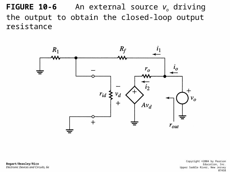
FIGURE 10-6 An external source vo driving the output to obtain the closed-loop output resistance
Bogart/Beasley/RicoElectronic Devices and Circuits, 6e
Copyright ©2004 by Pearson Education, Inc.Upper Saddle River, New Jersey 07458
All rights reserved.

Chapter 10 Operational Amplifier Theory and Performance
Modeling an Operational Amplifier Feedback Theory oFeedback in the Noninverting Amplifier oNoninverting Input/Output Resistance Frequency Response oStability oThe Gain-Bandwidth Product Slew Rate
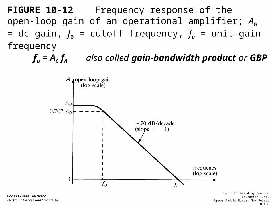
FIGURE 10-12 Frequency response of the open-loop gain of an operational amplifier; A0 = dc gain, f0 = cutoff frequency, fu = unit-gain frequency
Bogart/Beasley/RicoElectronic Devices and Circuits, 6e
Copyright ©2004 by Pearson Education, Inc.Upper Saddle River, New Jersey 07458
All rights reserved.
fu = A0 f0 also called gain-bandwidth product or GBP

Closed-loop bandwidth BWCL
BWCL = fuβ = A0f0β = βGBP
Where β is the feedback ratioAny point along the sloped portion of the open-loop gain plot satisfies the relationship
gain x frequency = GBP
Only minimum guaranteed A0 is given f0 is not known, but GBP is always given

FIGURE 10-13 (Example 10-5)
Bogart/Beasley/RicoElectronic Devices and Circuits, 6e
Copyright ©2004 by Pearson Education, Inc.Upper Saddle River, New Jersey 07458
All rights reserved.
Example 10-5 Each of the op-amp has an open-loop GBP equal to 1 x 10⁶ Hz. Find the cutoff frequencies in the closed-loop configurations shown.
BWCL = fuβ = A0f0β = βGBP

FIGURE 10-14 Closed-loop gain vs. frequency for noninverting and inverting amplifiers
Bogart/Beasley/RicoElectronic Devices and Circuits, 6e
Copyright ©2004 by Pearson Education, Inc.Upper Saddle River, New Jersey 07458
All rights reserved.
2
1
c
CLOCL
ff
AA
where ACLO = 1 + Rf /R1 (noninverting)or ACLO = Rf /R1 (inverting)and fc = β GBP

FIGURE 10-15 Open-loop frequency response for the op-amp in Example 10-6Bogart/Beasley/RicoElectronic Devices and Circuits, 6e
Copyright ©2004 by Pearson Education, Inc.Upper Saddle River, New Jersey 07458
All rights reserved.
Example 10-6 With reference to the op-amp whose open-loop frequency response is shown in the following figure, find1.The unity-gain frequency,2.The open-loop 3-dB frequency,3.The BW when the feedback ration is 0.02, and4.The closed-loop gain at 0.4 MHz when the feedback ration is 0.04

Chapter 10 Operational Amplifier Theory and Performance
Modeling an Operational Amplifier Feedback Theory oFeedback in the Noninverting Amplifier oNoninverting Input/Output Resistance Frequency Response oStability oThe Gain-Bandwidth Product Slew Rate

FIGURE 10-17 The rate of change of a linear, or ramp, signal is the change in voltage divided by the change in time
Bogart/Beasley/RicoElectronic Devices and Circuits, 6e
Copyright ©2004 by Pearson Education, Inc.Upper Saddle River, New Jersey 07458
All rights reserved.
The maximum possible rate at which an amplifier’s output voltage can change, in volts per second, is called its slew rate.

FIGURE 10-18 (Example 10-7)
Bogart/Beasley/RicoElectronic Devices and Circuits, 6e
Copyright ©2004 by Pearson Education, Inc.Upper Saddle River, New Jersey 07458
All rights reserved.
Example 10-7 The op-amp has a slew-rate specification of 0.5 V/µs. If the input is the ramp waveform shown, what is the maximum closed-loop gain that the amplifier can have without exceeding its slew rate?

ConclusionThe maximum frequency at which an amplifier can be operated depends on both bandwidth and the slew rate
The rate change of vo(t) = Vp sin ωt is (Vpω) volts/second
so Vp ω Sor 2πf Vp S
where S is the specified slew rate of an amplifier
fs (max) S/(2πVp)and
f (max) BWCL

FIGURE 10-19 (Example 10-8)Bogart/Beasley/RicoElectronic Devices and Circuits, 6e
Copyright ©2004 by Pearson Education, Inc.Upper Saddle River, New Jersey 07458
All rights reserved.
Example 10-19 The op-amp has a slew rate of 0.5 V/µs. The amp must be capable of amplifying the following input signals:v1 = 0.01 sin (106t),v2 = 0.05 sin (350 x 103t),v3 = 0.1 sin (200 x 103t), andv4 = 0.2 sin (50 x 103t).1.Determine whether the output will be distorted due to slew-rate limitations on any input.2.If so, find a remedy (other than changing the input signals).

FIGURE 10-20 (Example 10-9) Bogart/Beasley/RicoElectronic Devices and Circuits, 6e
Copyright ©2004 by Pearson Education, Inc.Upper Saddle River, New Jersey 07458
All rights reserved.
Example 10-9 The op-amp has a unity-gain frequency of 1 MHz (fu) and a slew rate of 1 V/µs. Find the maximum frequency of a 0.1-V-peak sine-wave input that can be amplified without slew-rate distortion.