chapter 10 mechanical springs -...
TRANSCRIPT

Chapter 10
Mechanical Springs
1/2/2015 2:11 PM
Dr. Mohammad Suliman Abuhaiba, PE 1
Chapter Outline
1/2/2015 2:11 PM
Dr. Mohammad Suliman Abuhaiba, PE
2
Stresses in Helical Springs
The Curvature Effect
Deflection of Helical Springs
Compression Springs
Stability
Spring Materials
Helical Compression Spring Design for Static Service
Critical Frequency of Helical Springs
Fatigue Loading of Helical Compression Springs
Helical Compression Spring Design for Fatigue Loading
Extension Springs
Helical Coil Torsion Springs
Belleville Springs
Springs Classification
1. Wire springs
helical springs of round or square wire, made
to resist and deflect under tensile,
compressive, or torsional loads.
2. Flat springs
a. cantilever and elliptical types,
b. wound motor- or clock-type power springs
c. flat spring washers (Belleville springs)
3. Special shaped springs
1/2/2015 2:11 PM
Dr. Mohammad Suliman Abuhaiba, PE
3
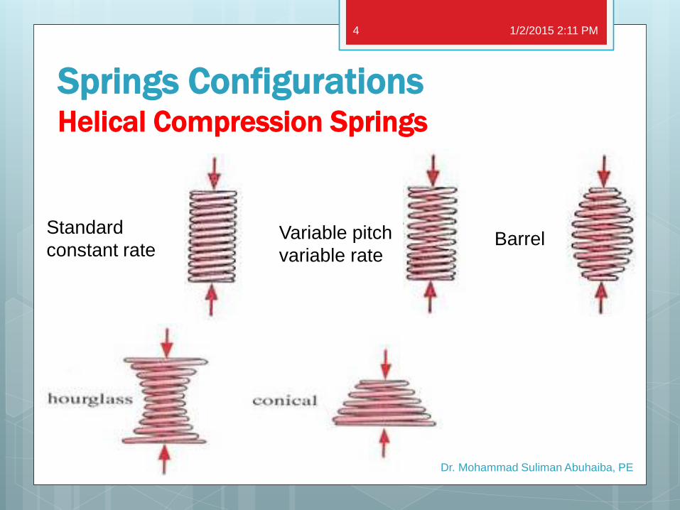
Springs Configurations Helical Compression Springs
1/2/2015 2:11 PM
Dr. Mohammad Suliman Abuhaiba, PE
4
Standard
constant rate Variable pitch
variable rate Barrel
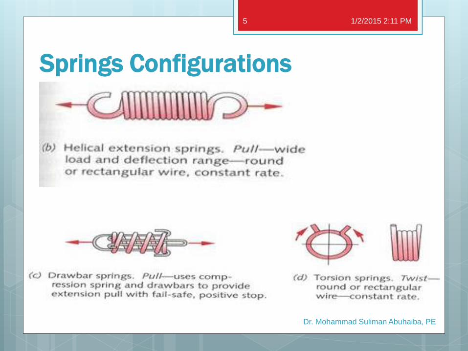
Springs Configurations
1/2/2015 2:11 PM
Dr. Mohammad Suliman Abuhaiba, PE
5
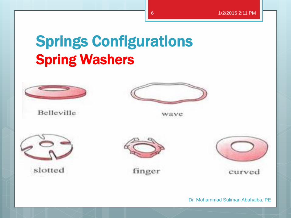
Springs Configurations Spring Washers
1/2/2015 2:11 PM
Dr. Mohammad Suliman Abuhaiba, PE
6
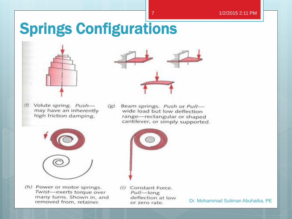
Springs Configurations
1/2/2015 2:11 PM
Dr. Mohammad Suliman Abuhaiba, PE
7
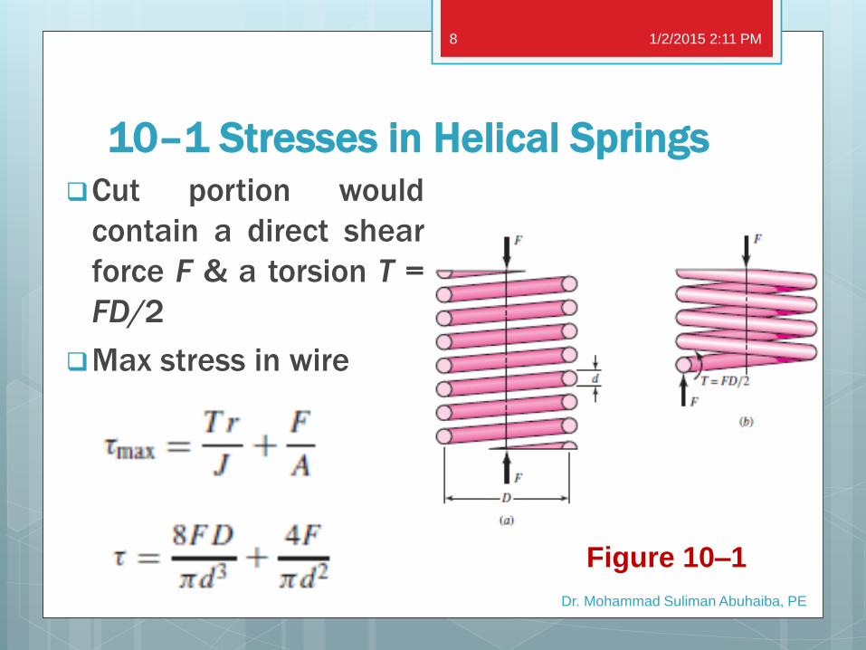
10–1 Stresses in Helical Springs
Cut portion would
contain a direct shear
force F & a torsion T =
FD/2
Max stress in wire
1/2/2015 2:11 PM
Dr. Mohammad Suliman Abuhaiba, PE
8
Figure 10–1
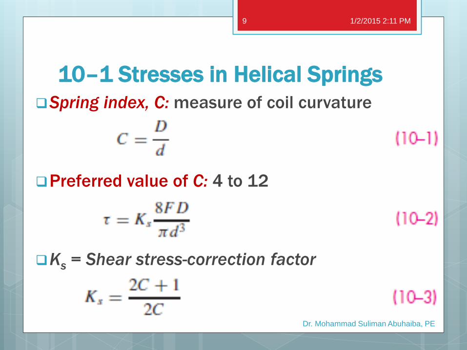
10–1 Stresses in Helical Springs
Spring index, C: measure of coil curvature
Preferred value of C: 4 to 12
Ks = Shear stress-correction factor
1/2/2015 2:11 PM
Dr. Mohammad Suliman Abuhaiba, PE
9
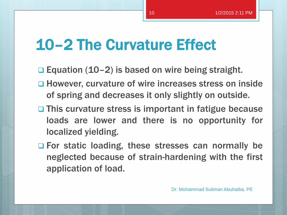
10–2 The Curvature Effect
Equation (10–2) is based on wire being straight.
However, curvature of wire increases stress on inside
of spring and decreases it only slightly on outside.
This curvature stress is important in fatigue because
loads are lower and there is no opportunity for
localized yielding.
For static loading, these stresses can normally be
neglected because of strain-hardening with the first
application of load.
1/2/2015 2:11 PM
Dr. Mohammad Suliman Abuhaiba, PE
10
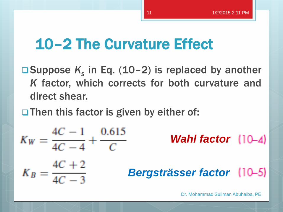
10–2 The Curvature Effect
Suppose Ks in Eq. (10–2) is replaced by another
K factor, which corrects for both curvature and
direct shear.
Then this factor is given by either of:
1/2/2015 2:11 PM
Dr. Mohammad Suliman Abuhaiba, PE
11
Wahl factor
Bergsträsser factor
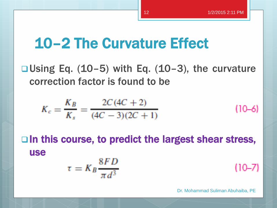
10–2 The Curvature Effect
Using Eq. (10–5) with Eq. (10–3), the curvature
correction factor is found to be
In this course, to predict the largest shear stress,
use
1/2/2015 2:11 PM
Dr. Mohammad Suliman Abuhaiba, PE
12
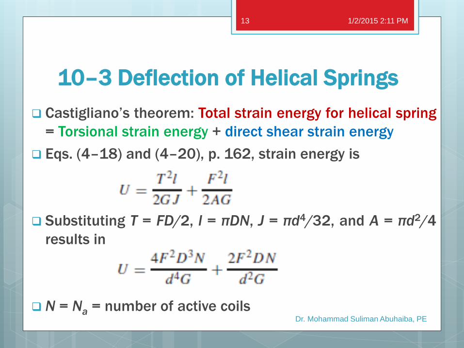
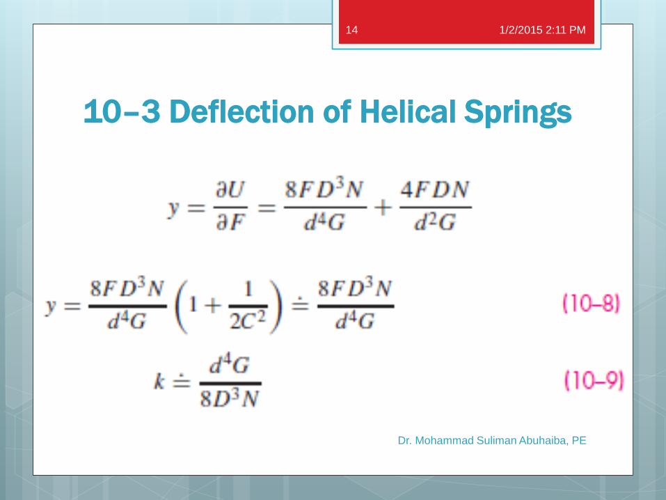
10–3 Deflection of Helical Springs
Castigliano’s theorem: Total strain energy for helical spring
= Torsional strain energy + direct shear strain energy
Eqs. (4–18) and (4–20), p. 162, strain energy is
Substituting T = FD/2, l = πDN, J = πd4/32, and A = πd2/4
results in
N = Na = number of active coils
1/2/2015 2:11 PM
Dr. Mohammad Suliman Abuhaiba, PE
13
10–3 Deflection of Helical Springs
1/2/2015 2:11 PM
Dr. Mohammad Suliman Abuhaiba, PE
14
10–4 Compression Springs
1/2/2015 2:11 PM
Dr. Mohammad Suliman Abuhaiba, PE
15
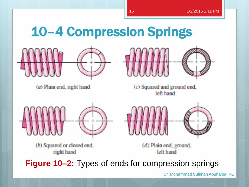
Figure 10–2: Types of ends for compression springs
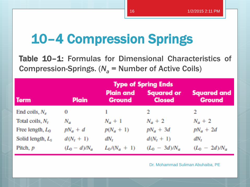
10–4 Compression Springs
Table 10–1: Formulas for Dimensional Characteristics of
Compression-Springs. (Na = Number of Active Coils)
1/2/2015 2:11 PM
Dr. Mohammad Suliman Abuhaiba, PE
16
10–4 Compression Springs Set removal (SR) or presetting
A process used in manufacture of compression
springs to induce useful residual stresses.
Done by making spring longer than needed and
then compressing it to its solid height.
SR sets the spring to required final free length
Since torsional yield strength has been exceeded,
induces residual stresses opposite in direction to
those induced in service.
1/2/2015 2:11 PM
Dr. Mohammad Suliman Abuhaiba, PE
17
10–4 Compression Springs Set removal or presetting
Springs to be preset should be designed so that
10 to 30 % of initial free length is removed during
the operation.
SR increases strength of spring and so is
especially useful when spring is used for energy-
storage purposes.
SR should not be used when springs are subject
to fatigue.
1/2/2015 2:11 PM
Dr. Mohammad Suliman Abuhaiba, PE
18
10–5 Stability
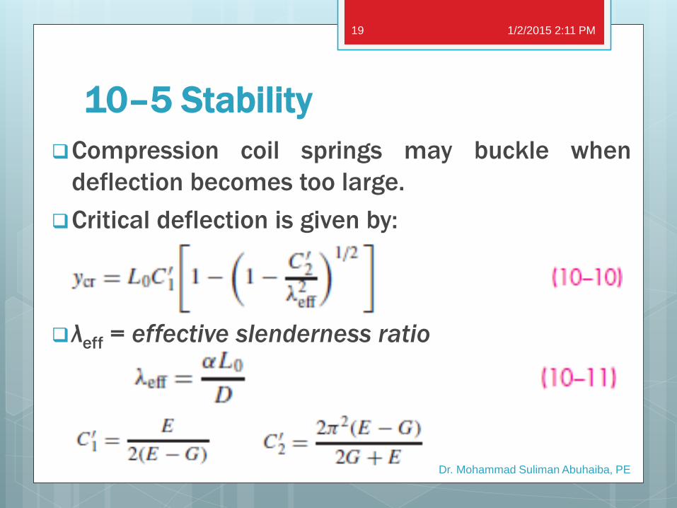
Compression coil springs may buckle when
deflection becomes too large.
Critical deflection is given by:
λeff = effective slenderness ratio
1/2/2015 2:11 PM
Dr. Mohammad Suliman Abuhaiba, PE
19
10–5 Stability
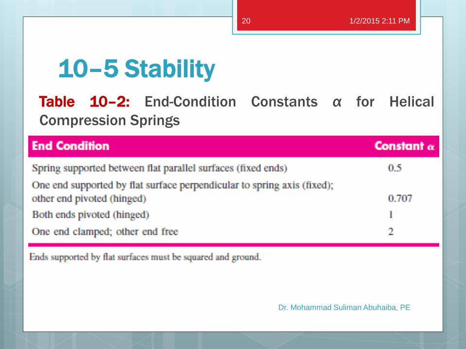
Table 10–2: End-Condition Constants α for Helical
Compression Springs
1/2/2015 2:11 PM
Dr. Mohammad Suliman Abuhaiba, PE
20
10–5 Stability
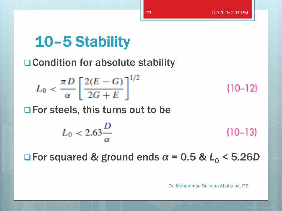
Condition for absolute stability
For steels, this turns out to be
For squared & ground ends α = 0.5 & L0 < 5.26D
1/2/2015 2:11 PM
Dr. Mohammad Suliman Abuhaiba, PE
21
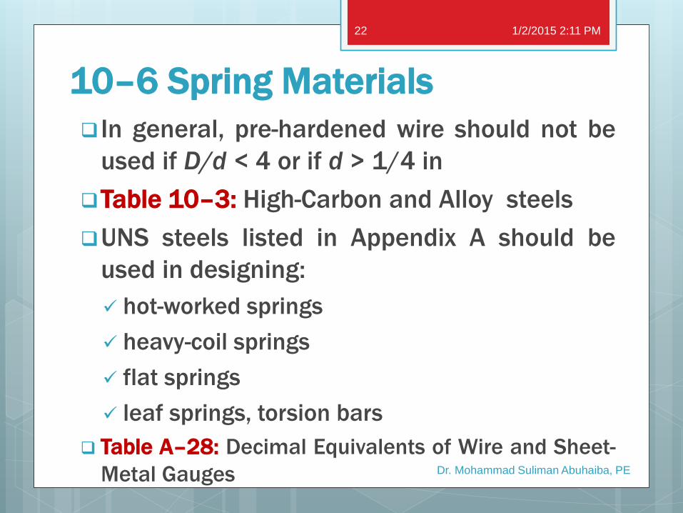
10–6 Spring Materials
In general, pre-hardened wire should not be
used if D/d < 4 or if d > 1/4 in
Table 10–3: High-Carbon and Alloy steels
UNS steels listed in Appendix A should be
used in designing:
hot-worked springs
heavy-coil springs
flat springs
leaf springs, torsion bars
Table A–28: Decimal Equivalents of Wire and Sheet-
Metal Gauges
1/2/2015 2:11 PM
Dr. Mohammad Suliman Abuhaiba, PE
22
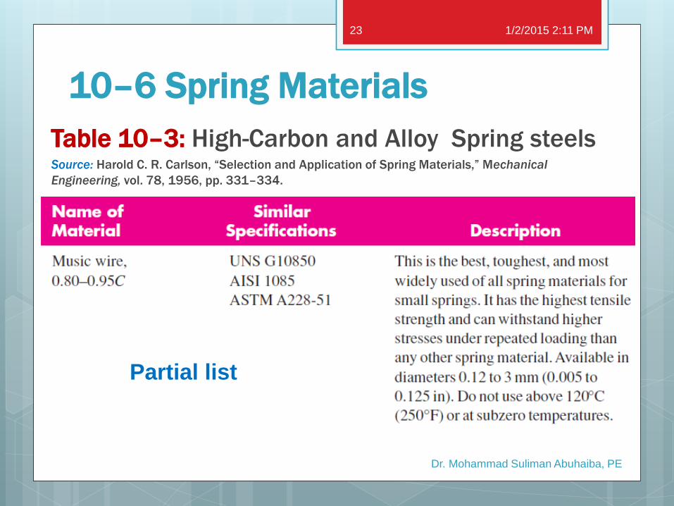
10–6 Spring Materials
Table 10–3: High-Carbon and Alloy Spring steels Source: Harold C. R. Carlson, “Selection and Application of Spring Materials,” Mechanical
Engineering, vol. 78, 1956, pp. 331–334.
1/2/2015 2:11 PM
Dr. Mohammad Suliman Abuhaiba, PE
23
Partial list
10–6 Spring Materials
1/2/2015 2:11 PM
Dr. Mohammad Suliman Abuhaiba, PE
24
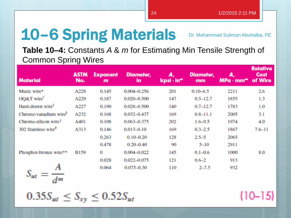
Table 10–4: Constants A & m for Estimating Min Tensile Strength of
Common Spring Wires
10–6 Spring Materials
1/2/2015 2:11 PM
Dr. Mohammad Suliman Abuhaiba, PE
25
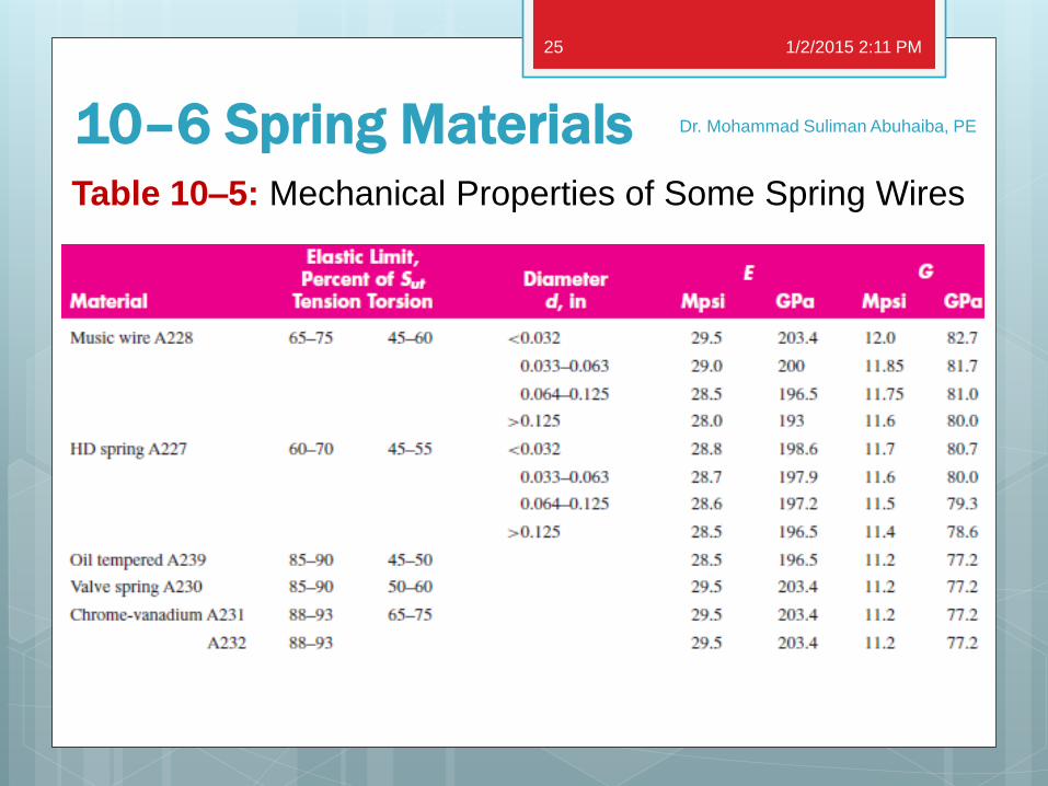
Table 10–5: Mechanical Properties of Some Spring Wires
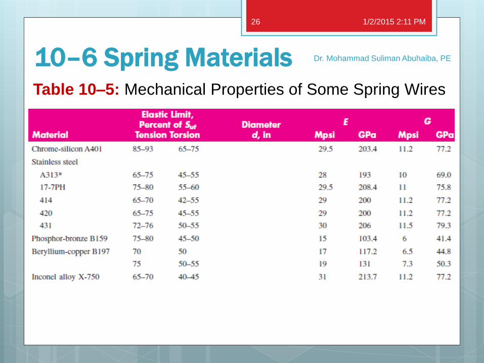
10–6 Spring Materials
1/2/2015 2:11 PM
Dr. Mohammad Suliman Abuhaiba, PE
26
Table 10–5: Mechanical Properties of Some Spring Wires
10–6 Spring Materials
1/2/2015 2:11 PM
Dr. Mohammad Suliman Abuhaiba, PE
27
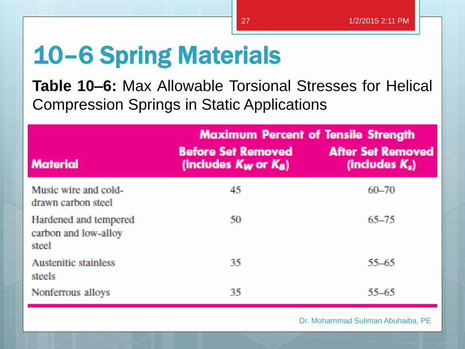
Table 10–6: Max Allowable Torsional Stresses for Helical
Compression Springs in Static Applications
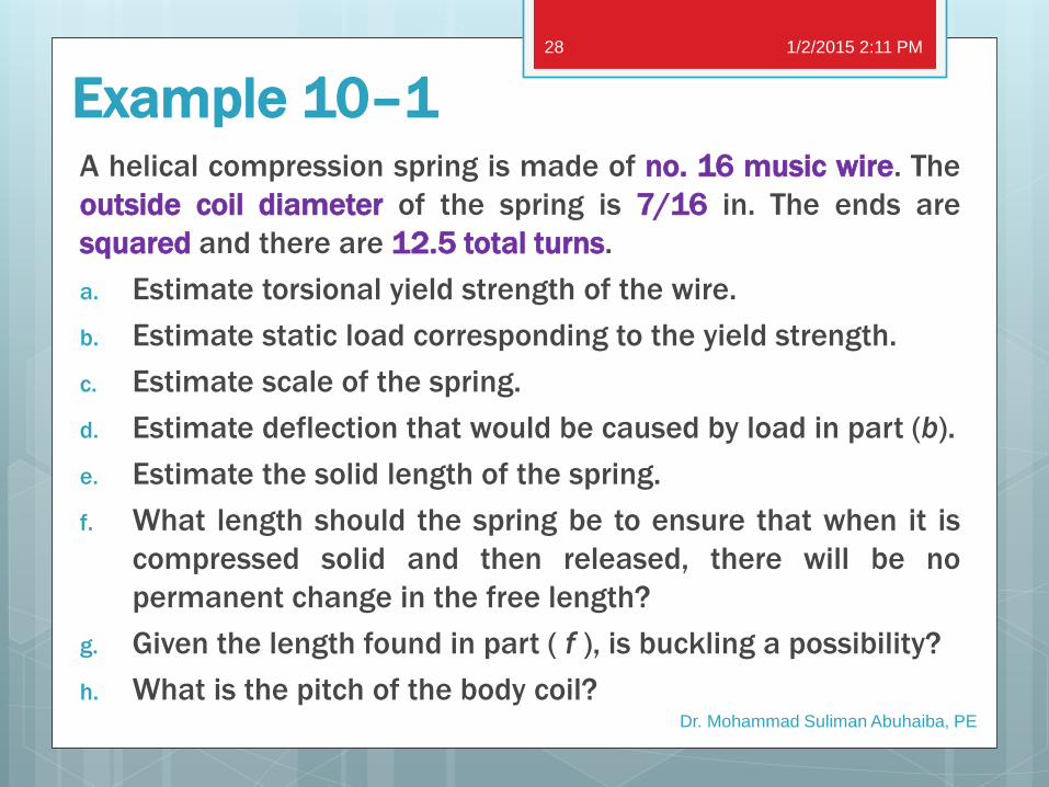
Example 10–1 A helical compression spring is made of no. 16 music wire. The
outside coil diameter of the spring is 7/16 in. The ends are
squared and there are 12.5 total turns.
a. Estimate torsional yield strength of the wire.
b. Estimate static load corresponding to the yield strength.
c. Estimate scale of the spring.
d. Estimate deflection that would be caused by load in part (b).
e. Estimate the solid length of the spring.
f. What length should the spring be to ensure that when it is
compressed solid and then released, there will be no
permanent change in the free length?
g. Given the length found in part ( f ), is buckling a possibility?
h. What is the pitch of the body coil?
1/2/2015 2:11 PM
Dr. Mohammad Suliman Abuhaiba, PE
28
10–7 Helical Compression Spring Design for Static Service
1. Spring index: 4 ≤ C ≤ 12
Lower indexes being more difficult to form because
of danger of surface cracking
Higher indexes tending to tangle often enough to
require individual packing
1/2/2015 2:11 PM
Dr. Mohammad Suliman Abuhaiba, PE
29
10–7 Helical Compression Spring Design for Static Service
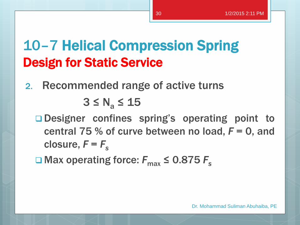
2. Recommended range of active turns
3 ≤ Na ≤ 15
Designer confines spring’s operating point to
central 75 % of curve between no load, F = 0, and
closure, F = Fs
Max operating force: Fmax ≤ 0.875 Fs
1/2/2015 2:11 PM
Dr. Mohammad Suliman Abuhaiba, PE
30
10–7 Helical Compression Spring Design for Static Service
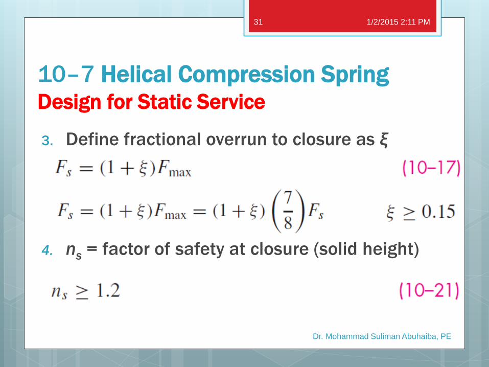
3. Define fractional overrun to closure as ξ
4. ns = factor of safety at closure (solid height)
1/2/2015 2:11 PM
Dr. Mohammad Suliman Abuhaiba, PE
31
10–7 Helical Compression Spring Design for Static Service
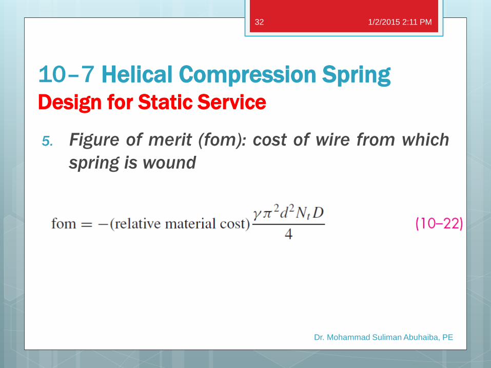
5. Figure of merit (fom): cost of wire from which
spring is wound
1/2/2015 2:11 PM
Dr. Mohammad Suliman Abuhaiba, PE
32
10–7 Helical Compression Spring Design for Static Service
Spring Design Software
Advanced Spring Design: a program developed jointly
between Spring Manufacturers Institute (SMI),
www.smihq.org, and Universal Technical Systems, Inc.
(UTS), www.uts.com.
MatLab
Mathematica
Spread Sheet (MS Excel)
Some Major Spring Manufactures offer free software
consultation for spring selection
1/2/2015 2:11 PM
Dr. Mohammad Suliman Abuhaiba, PE
33
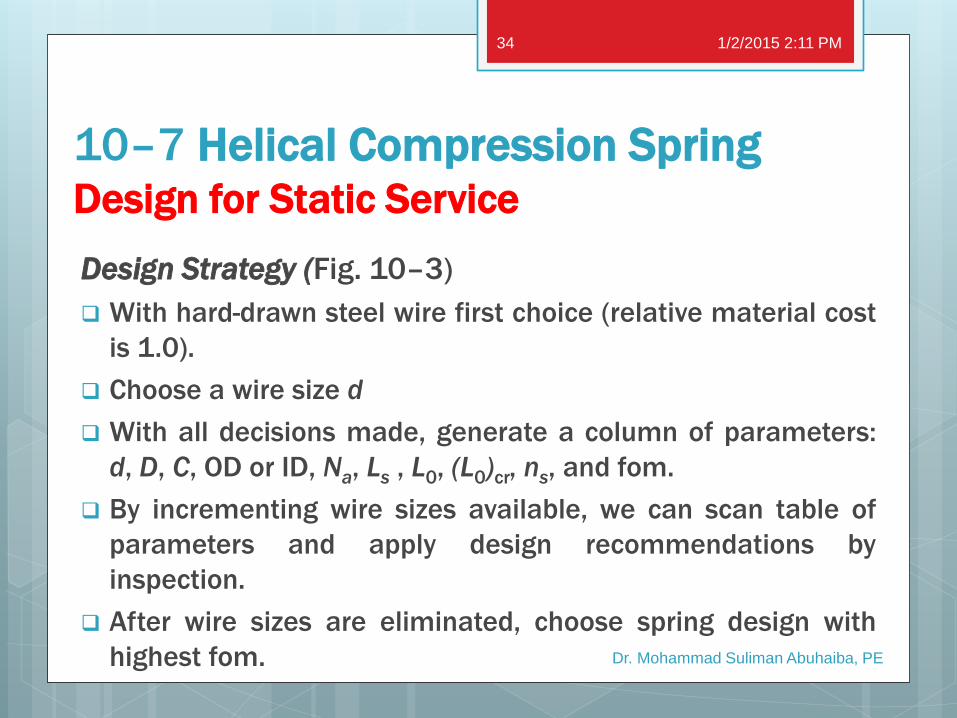
10–7 Helical Compression Spring Design for Static Service
Design Strategy (Fig. 10–3)
With hard-drawn steel wire first choice (relative material cost
is 1.0).
Choose a wire size d
With all decisions made, generate a column of parameters:
d, D, C, OD or ID, Na, Ls , L0, (L0)cr, ns, and fom.
By incrementing wire sizes available, we can scan table of
parameters and apply design recommendations by
inspection.
After wire sizes are eliminated, choose spring design with
highest fom.
1/2/2015 2:11 PM
Dr. Mohammad Suliman Abuhaiba, PE
34
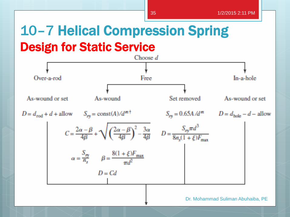
10–7 Helical Compression Spring Design for Static Service
1/2/2015 2:11 PM
Dr. Mohammad Suliman Abuhaiba, PE
35
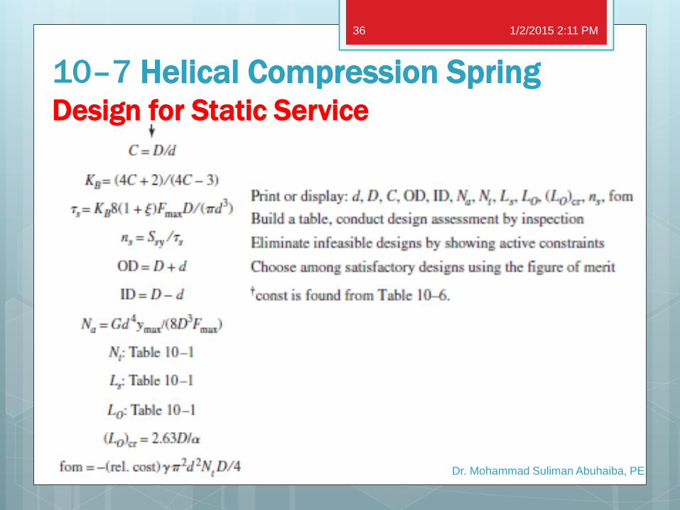
10–7 Helical Compression Spring Design for Static Service
1/2/2015 2:11 PM
Dr. Mohammad Suliman Abuhaiba, PE
36
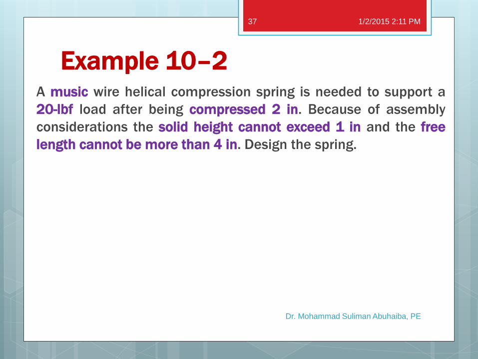
Example 10–2 A music wire helical compression spring is needed to support a
20-lbf load after being compressed 2 in. Because of assembly
considerations the solid height cannot exceed 1 in and the free
length cannot be more than 4 in. Design the spring.
1/2/2015 2:11 PM
Dr. Mohammad Suliman Abuhaiba, PE
37
Example 10–3 Design a compression spring with plain ends using hard-drawn wire.
The deflection is to be 2.25 in when the force is 18 lbf and to close solid
when the force is 24 lbf. Upon closure, use a design factor of 1.2
guarding against yielding. Select the smallest gauge W&M (Washburn
& Moen) wire.
1/2/2015 2:11 PM
Dr. Mohammad Suliman Abuhaiba, PE
38
10–8 Critical Frequency of Helical Springs
spring surge: If one end of a compression
spring is held against a flat surface and the
other end is disturbed, a compression wave
is created that travels back and forth from
one end to the other exactly like the
swimming-pool wave.
1/2/2015 2:11 PM
Dr. Mohammad Suliman Abuhaiba, PE
39
10–8 Critical Frequency of Helical Springs
When helical springs are used in applications
requiring a rapid reciprocating motion, the
designer must be certain that the physical
dimensions of the spring are not such as to
create a natural vibratory frequency close to
the frequency of the applied force;
otherwise, resonance may occur, resulting
in damaging stresses, since the internal
damping of spring materials is quite low.
1/2/2015 2:11 PM
Dr. Mohammad Suliman Abuhaiba, PE
40
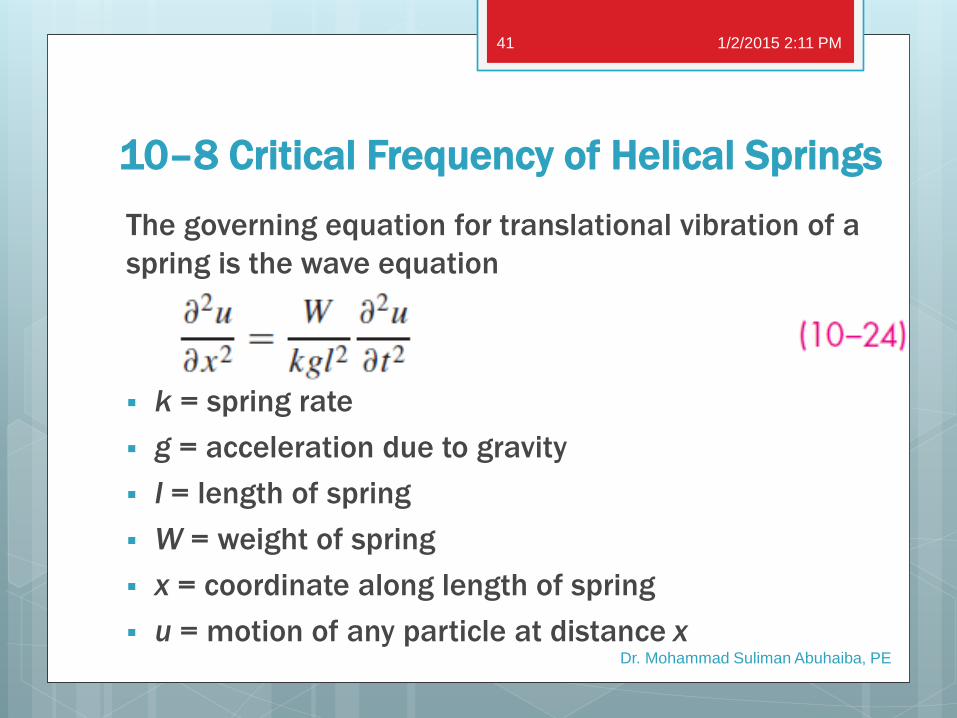
10–8 Critical Frequency of Helical Springs
The governing equation for translational vibration of a
spring is the wave equation
k = spring rate
g = acceleration due to gravity
l = length of spring
W = weight of spring
x = coordinate along length of spring
u = motion of any particle at distance x
1/2/2015 2:11 PM
Dr. Mohammad Suliman Abuhaiba, PE
41
10–8 Critical Frequency of Helical Springs
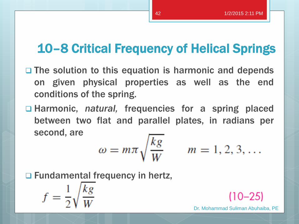
The solution to this equation is harmonic and depends
on given physical properties as well as the end
conditions of the spring.
Harmonic, natural, frequencies for a spring placed
between two flat and parallel plates, in radians per
second, are
Fundamental frequency in hertz,
1/2/2015 2:11 PM
Dr. Mohammad Suliman Abuhaiba, PE
42
10–8 Critical Frequency of Helical Springs
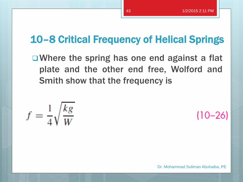
Where the spring has one end against a flat
plate and the other end free, Wolford and
Smith show that the frequency is
1/2/2015 2:11 PM
Dr. Mohammad Suliman Abuhaiba, PE
43
10–8 Critical Frequency of Helical Springs
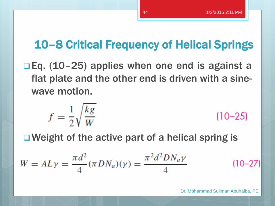
Eq. (10–25) applies when one end is against a
flat plate and the other end is driven with a sine-
wave motion.
Weight of the active part of a helical spring is
1/2/2015 2:11 PM
Dr. Mohammad Suliman Abuhaiba, PE
44
10–8 Critical Frequency of Helical Springs
Fundamental critical frequency > 15 to 20
times frequency of force or motion of spring
in order to avoid resonance with the
harmonics.
If frequency is not high enough, spring
should be redesigned to increase k or
decrease W.
1/2/2015 2:11 PM
Dr. Mohammad Suliman Abuhaiba, PE
45
10–9 Fatigue Loading of Helical
Compression Springs
Shot peening is used to improve fatigue strength
of dynamically loaded springs.
It can increase torsional fatigue strength by 20 %
or more
Zimmerli: size, material, and tensile strength
have no effect on endurance limits (infinite life)
of spring steels in sizes under 3/8 in (10 mm).
1/2/2015 2:11 PM
Dr. Mohammad Suliman Abuhaiba, PE
46
10–9 Fatigue Loading of Helical
Compression Springs
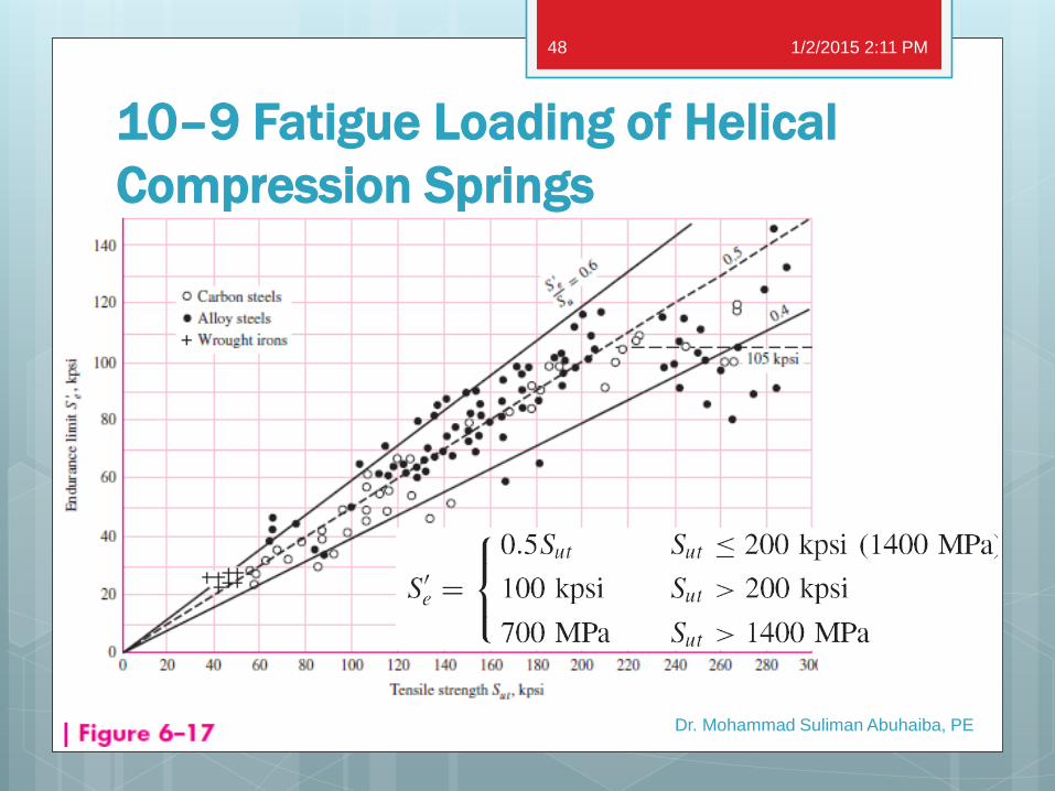
Endurance limits tend to level out at high tensile
strengths (Fig. 6–17)
Un-peened springs were tested from a min
torsional stress of 20 kpsi to a max of 90 kpsi
and peened springs in the range 20 kpsi to 135
kpsi.
1/2/2015 2:11 PM
Dr. Mohammad Suliman Abuhaiba, PE
47
10–9 Fatigue Loading of Helical
Compression Springs
1/2/2015 2:11 PM
Dr. Mohammad Suliman Abuhaiba, PE
48
10–9 Fatigue Loading of Helical
Compression Springs
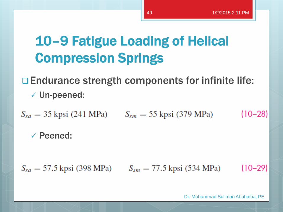
Endurance strength components for infinite life:
Un-peened:
Peened:
1/2/2015 2:11 PM
Dr. Mohammad Suliman Abuhaiba, PE
49
10–9 Fatigue Loading of Helical
Compression Springs
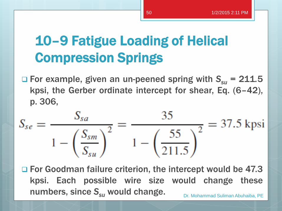
For example, given an un-peened spring with Ssu = 211.5
kpsi, the Gerber ordinate intercept for shear, Eq. (6–42),
p. 306,
For Goodman failure criterion, the intercept would be 47.3
kpsi. Each possible wire size would change these
numbers, since Ssu would change.
1/2/2015 2:11 PM
Dr. Mohammad Suliman Abuhaiba, PE
50

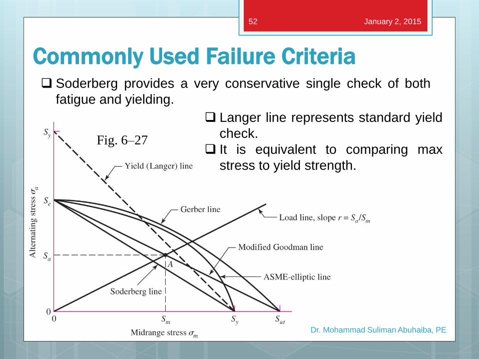
Commonly Used Failure Criteria Gerber passes through the data
ASME-elliptic passes through data & incorporates rough yielding
check
Dr. Mohammad Suliman Abuhaiba, PE
Fig. 6–27
January 2, 2015 51
Modified Goodman is linear, so
simple to use for design. It is more
conservative than Gerber.
Commonly Used Failure Criteria
Dr. Mohammad Suliman Abuhaiba, PE
Fig. 6–27
January 2, 2015 52
Soderberg provides a very conservative single check of both
fatigue and yielding.
Langer line represents standard yield
check.
It is equivalent to comparing max
stress to yield strength.
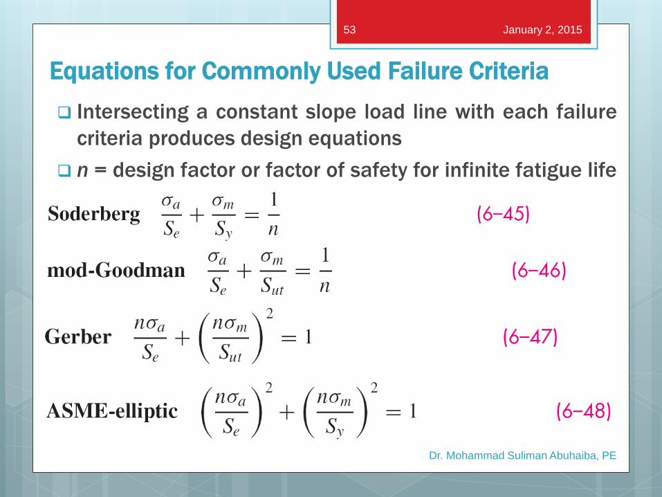
Equations for Commonly Used Failure Criteria
Intersecting a constant slope load line with each failure
criteria produces design equations
n = design factor or factor of safety for infinite fatigue life
Dr. Mohammad Suliman Abuhaiba, PE
January 2, 2015 53
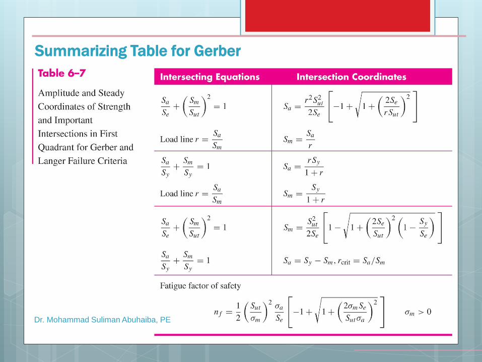
Summarizing Table for Gerber
Dr. Mohammad Suliman Abuhaiba, PE
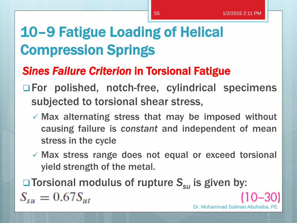
10–9 Fatigue Loading of Helical
Compression Springs
Sines Failure Criterion in Torsional Fatigue
For polished, notch-free, cylindrical specimens
subjected to torsional shear stress,
Max alternating stress that may be imposed without
causing failure is constant and independent of mean
stress in the cycle
Max stress range does not equal or exceed torsional
yield strength of the metal.
Torsional modulus of rupture Ssu is given by:
1/2/2015 2:11 PM
Dr. Mohammad Suliman Abuhaiba, PE
55
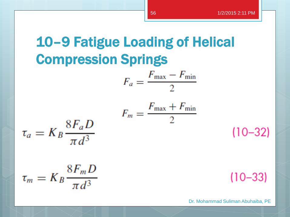
10–9 Fatigue Loading of Helical
Compression Springs
1/2/2015 2:11 PM
Dr. Mohammad Suliman Abuhaiba, PE
56
Example 10–4 An as-wound helical compression spring, made of music wire, has a
wire size of 0.092 in, an outside coil diameter of 9/16 in, a free
length of 4 3/8 in, 21 active coils, and both ends squared and
ground. The spring is unpeened. This spring is to be assembled with a
preload of 5 lbf and will operate with a maximum load of 35 lbf
during use.
a. Estimate factor of safety guarding against fatigue failure using a
torsional Gerber fatigue failure criterion with Zimmerli data.
b. Repeat part (a) using Sines torsional fatigue criterion (steady
stress component has no effect), with Zimmerli data.
c. Repeat using (a) torsional Goodman failure criterion with
Zimmerli data.
d. Estimate the critical frequency of the spring.
1/2/2015 2:11 PM
Dr. Mohammad Suliman Abuhaiba, PE
57
Example 10–5
A music wire helical compression spring with infinite life is
needed to resist a dynamic load that varies from 5 to 20
lbf at 5 Hz while the end deflection varies from 1/2 to 2 in.
Because of assembly considerations, the solid height
cannot exceed 1 in and the free length cannot be more
than 4 in. The spring maker has the following wire sizes in
stock: 0.069, 0.071, 0.080, 0.085, 0.090, 0.095, 0.105,
and 0.112 in.
1/2/2015 2:11 PM
Dr. Mohammad Suliman Abuhaiba, PE
58
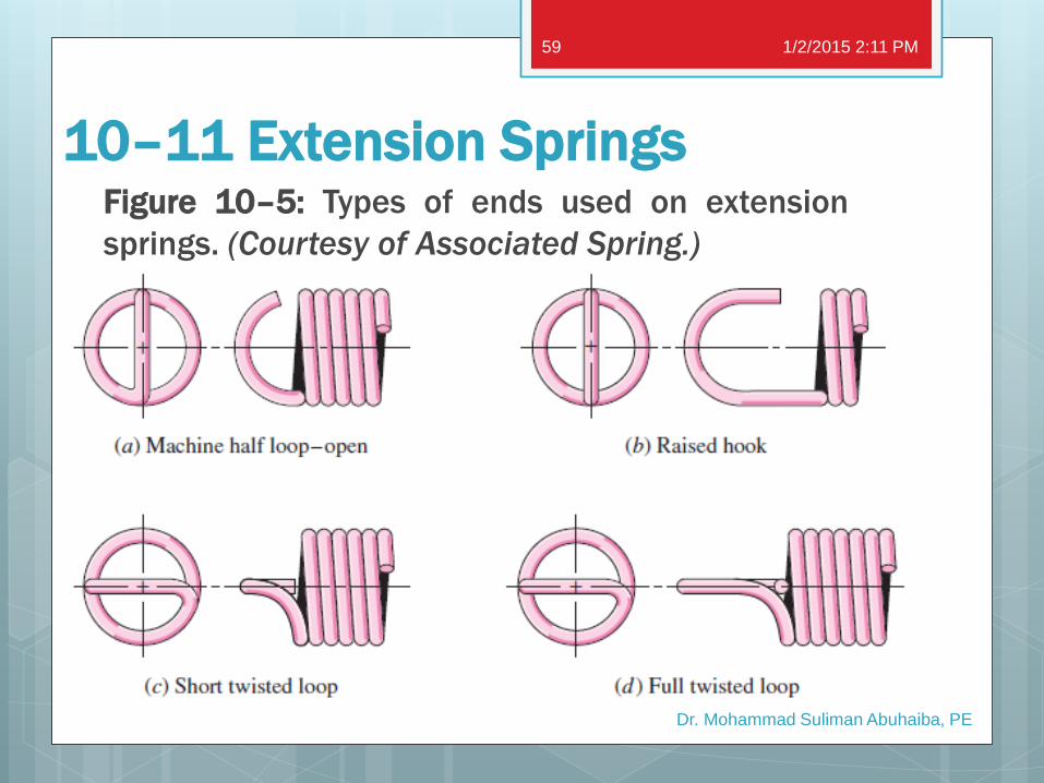
10–11 Extension Springs Figure 10–5: Types of ends used on extension
springs. (Courtesy of Associated Spring.)
1/2/2015 2:11 PM
Dr. Mohammad Suliman Abuhaiba, PE
59
10–11 Extension Springs
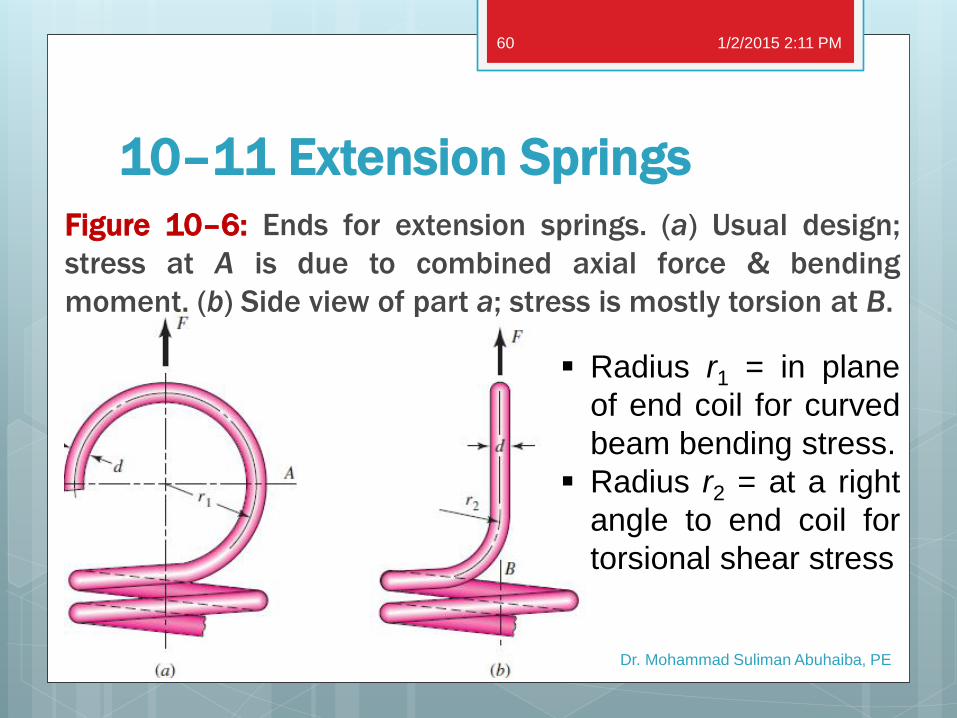
Figure 10–6: Ends for extension springs. (a) Usual design;
stress at A is due to combined axial force & bending
moment. (b) Side view of part a; stress is mostly torsion at B.
1/2/2015 2:11 PM
Dr. Mohammad Suliman Abuhaiba, PE
60
Radius r1 = in plane
of end coil for curved
beam bending stress.
Radius r2 = at a right
angle to end coil for
torsional shear stress
10–11 Extension Springs
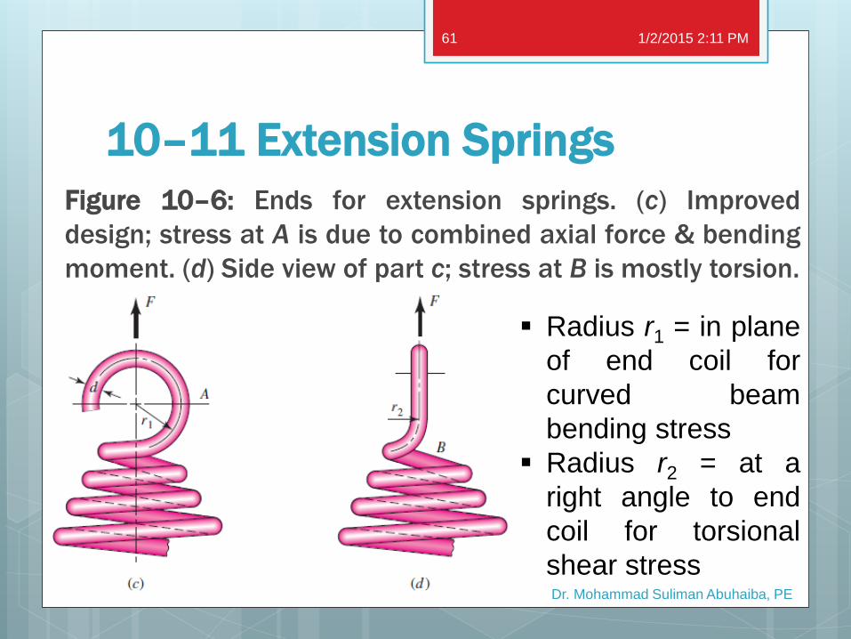
Figure 10–6: Ends for extension springs. (c) Improved
design; stress at A is due to combined axial force & bending
moment. (d) Side view of part c; stress at B is mostly torsion.
1/2/2015 2:11 PM
Dr. Mohammad Suliman Abuhaiba, PE
61
Radius r1 = in plane
of end coil for
curved beam
bending stress
Radius r2 = at a
right angle to end
coil for torsional
shear stress
10–11 Extension Springs
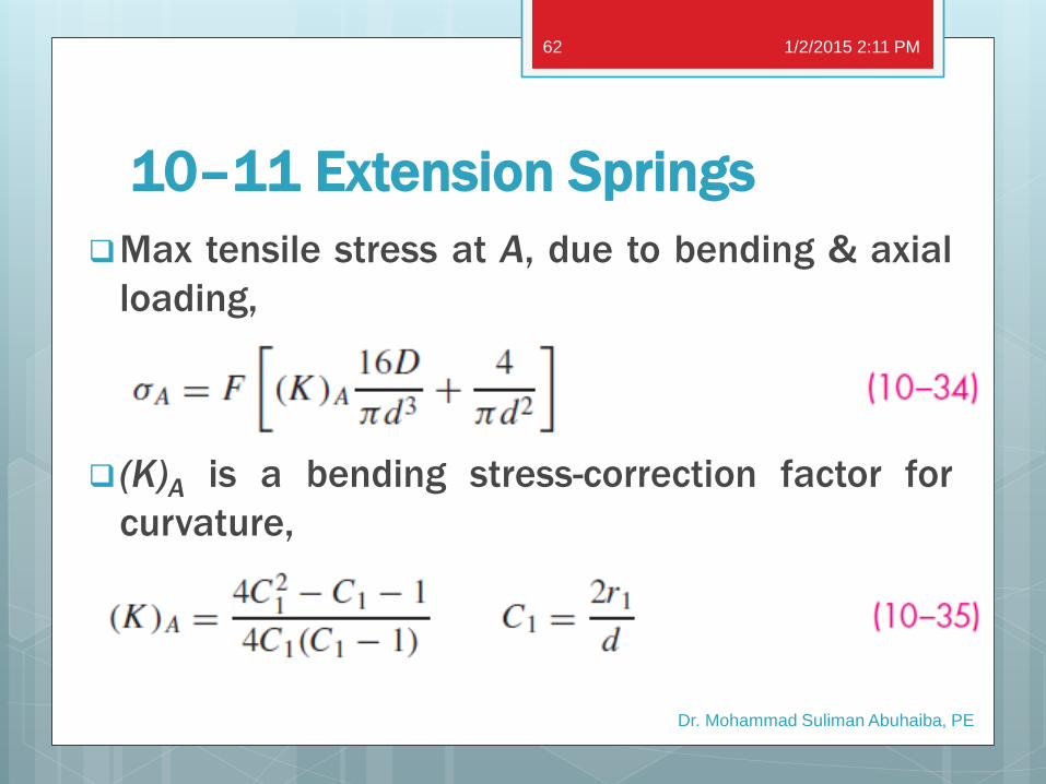
Max tensile stress at A, due to bending & axial
loading,
(K)A is a bending stress-correction factor for
curvature,
1/2/2015 2:11 PM
Dr. Mohammad Suliman Abuhaiba, PE
62
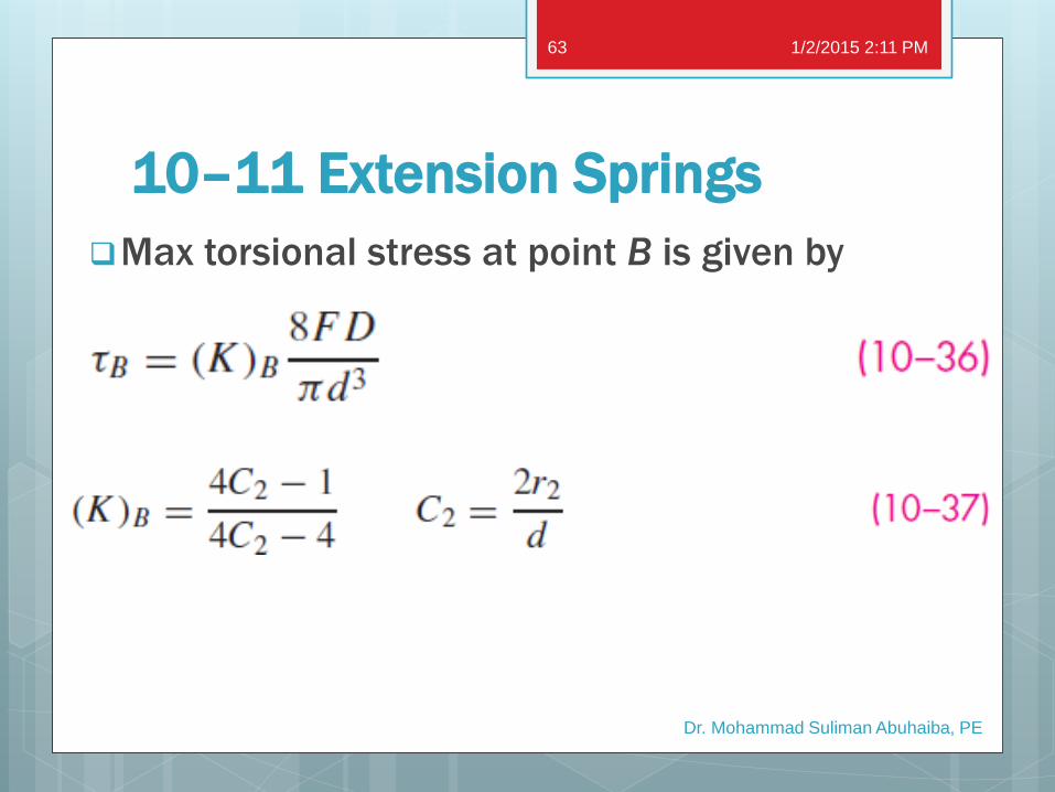
10–11 Extension Springs
Max torsional stress at point B is given by
1/2/2015 2:11 PM
Dr. Mohammad Suliman Abuhaiba, PE
63
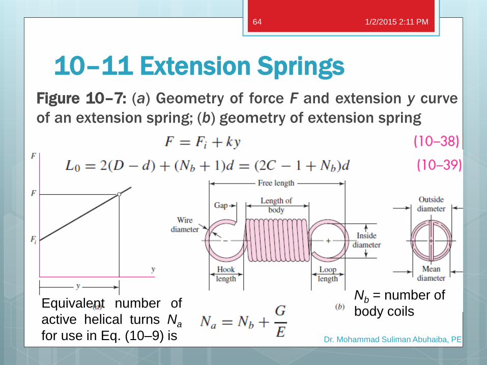
Figure 10–7: (a) Geometry of force F and extension y curve
of an extension spring; (b) geometry of extension spring
10–11 Extension Springs
1/2/2015 2:11 PM
Dr. Mohammad Suliman Abuhaiba, PE
64
Nb = number of
body coils Equivalent number of
active helical turns Na
for use in Eq. (10–9) is
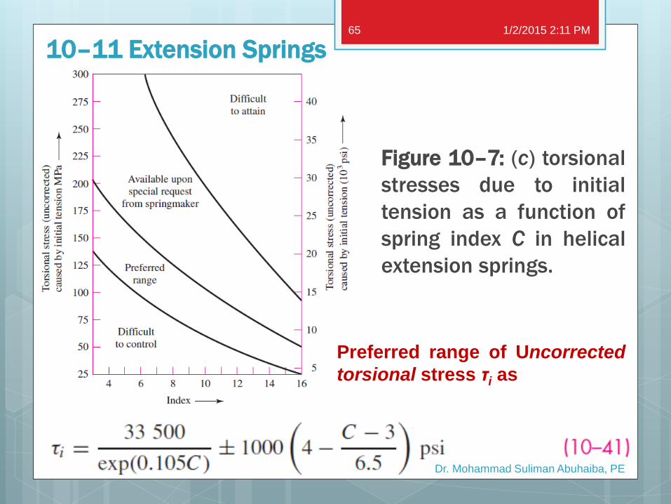
10–11 Extension Springs
Figure 10–7: (c) torsional
stresses due to initial
tension as a function of
spring index C in helical
extension springs.
1/2/2015 2:11 PM
Dr. Mohammad Suliman Abuhaiba, PE
65
Preferred range of Uncorrected
torsional stress τi as
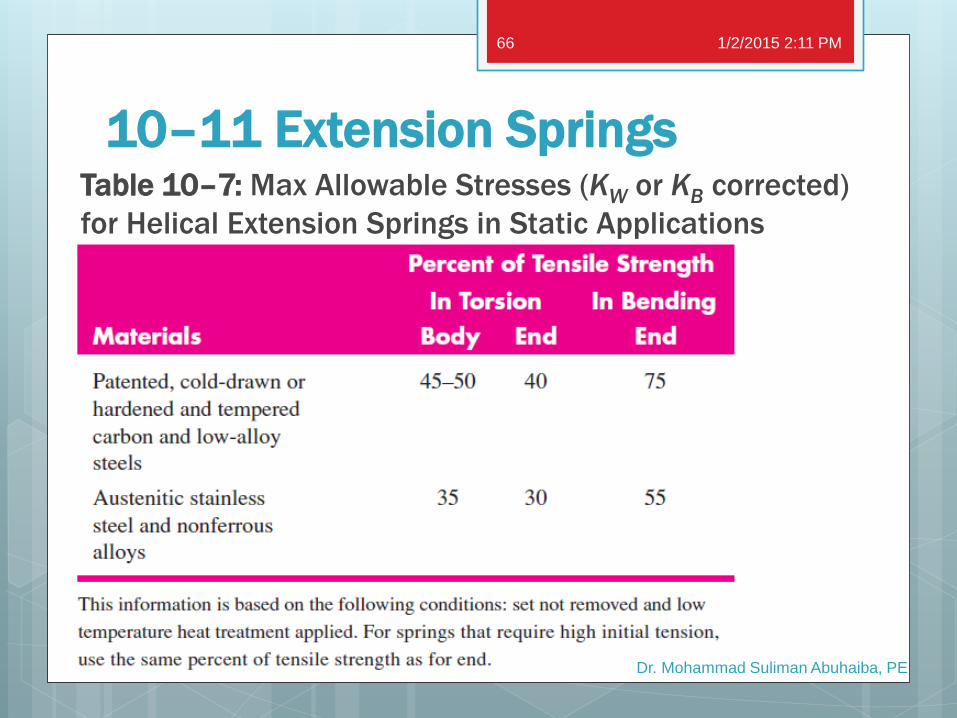
Table 10–7: Max Allowable Stresses (KW or KB corrected)
for Helical Extension Springs in Static Applications
10–11 Extension Springs
1/2/2015 2:11 PM
Dr. Mohammad Suliman Abuhaiba, PE
66
Example 10–6
A hard-drawn steel wire extension spring has a
wire diameter of 0.035 in, an outside coil diameter
of 0.248 in, hook radii of r1 = 0.106 in and r2 =
0.089 in, and an initial tension of 1.19 lbf. The
number of body turns is 12.17. From the given
information:
a. Determine physical parameters of the spring.
b. Check initial preload stress conditions.
c. Find factors of safety under a static 5.25-lbf
load.
1/2/2015 2:11 PM
Dr. Mohammad Suliman Abuhaiba, PE
67
Example 10–7
The helical coil extension spring of Ex. 10–6 is
subjected to a dynamic loading from 1.5 to 5 lbf.
Estimate the factors of safety using the Gerber
failure criterion for:
a. coil fatigue
b. coil yielding
c. end-hook bending fatigue at point A - Fig. 10–6a
d. end-hook torsional fatigue at point B - Fig. 10–6b
1/2/2015 2:11 PM
Dr. Mohammad Suliman Abuhaiba, PE
68
End hooks are usually the weakest part, with
bending usually controlling.
A fatigue failure separates the extension spring
under load.
Flying fragments, lost load, and machine
shutdown are threats to personal safety as well
as machine function.
For these reasons higher design factors are
used in extension-spring.
10–11 Extension Springs
1/2/2015 2:11 PM
Dr. Mohammad Suliman Abuhaiba, PE
69
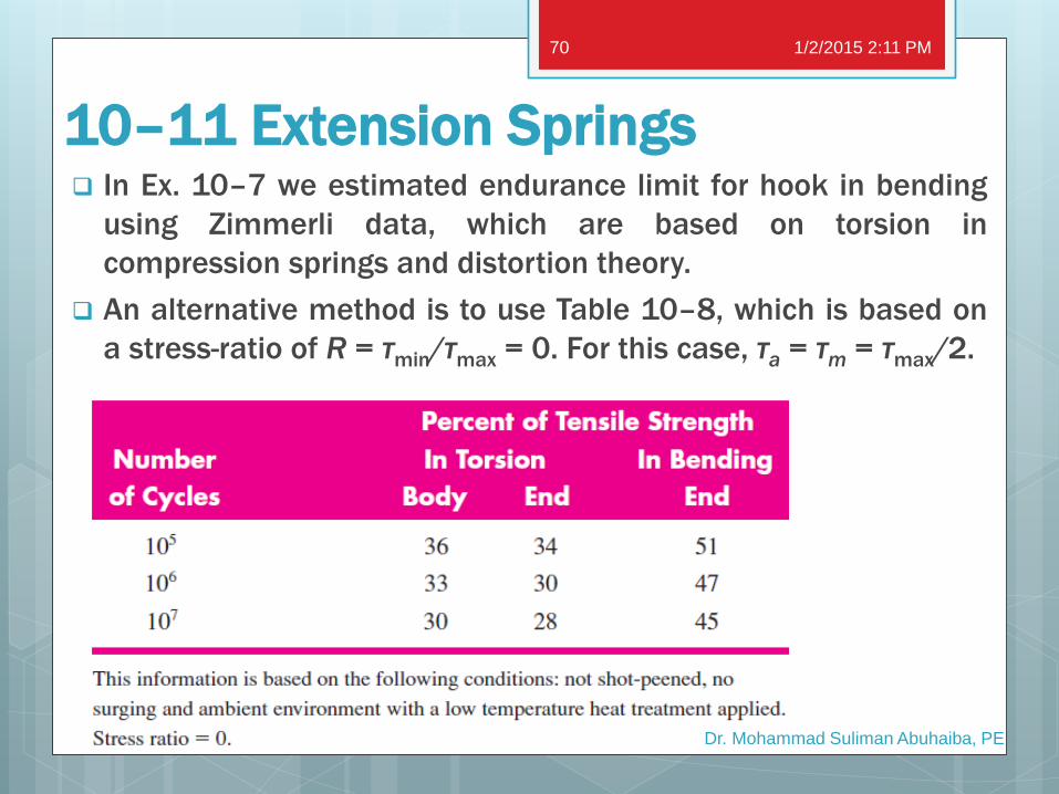
In Ex. 10–7 we estimated endurance limit for hook in bending
using Zimmerli data, which are based on torsion in
compression springs and distortion theory.
An alternative method is to use Table 10–8, which is based on
a stress-ratio of R = τmin/τmax = 0. For this case, τa = τm = τmax/2.
10–11 Extension Springs
1/2/2015 2:11 PM
Dr. Mohammad Suliman Abuhaiba, PE
70
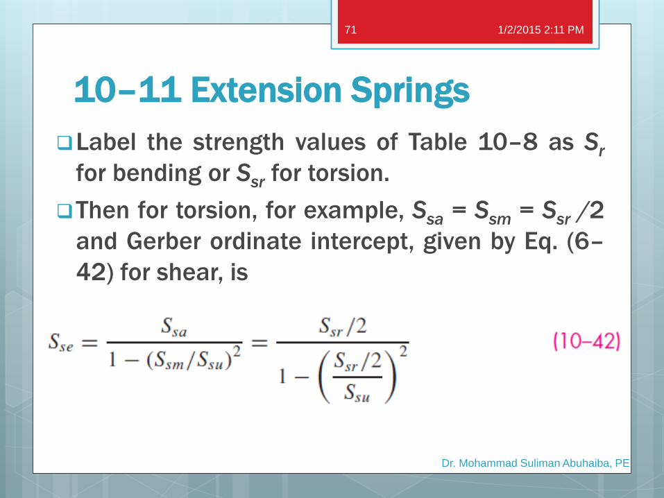
Label the strength values of Table 10–8 as Sr
for bending or Ssr for torsion.
Then for torsion, for example, Ssa = Ssm = Ssr /2
and Gerber ordinate intercept, given by Eq. (6–
42) for shear, is
10–11 Extension Springs
1/2/2015 2:11 PM
Dr. Mohammad Suliman Abuhaiba, PE
71
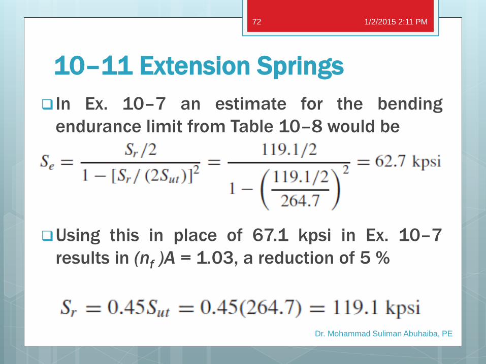
In Ex. 10–7 an estimate for the bending
endurance limit from Table 10–8 would be
Using this in place of 67.1 kpsi in Ex. 10–7
results in (nf )A = 1.03, a reduction of 5 %
10–11 Extension Springs
1/2/2015 2:11 PM
Dr. Mohammad Suliman Abuhaiba, PE
72
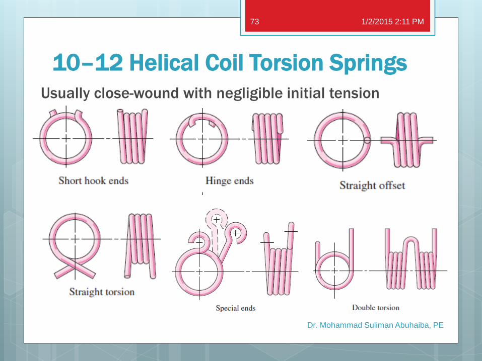
10–12 Helical Coil Torsion Springs
Usually close-wound with negligible initial tension
1/2/2015 2:11 PM
Dr. Mohammad Suliman Abuhaiba, PE
73
10–12 Helical Coil Torsion Springs
Wire in a torsion spring is in bending
As the applied torque increases, the
inside diameter of the coil decreases.
1/2/2015 2:11 PM
Dr. Mohammad Suliman Abuhaiba, PE
74
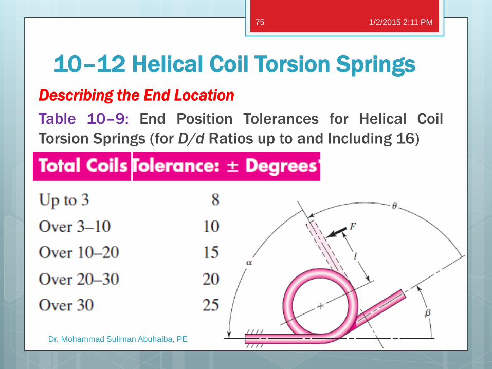
10–12 Helical Coil Torsion Springs
Describing the End Location
Table 10–9: End Position Tolerances for Helical Coil
Torsion Springs (for D/d Ratios up to and Including 16)
1/2/2015 2:11 PM
Dr. Mohammad Suliman Abuhaiba, PE
75
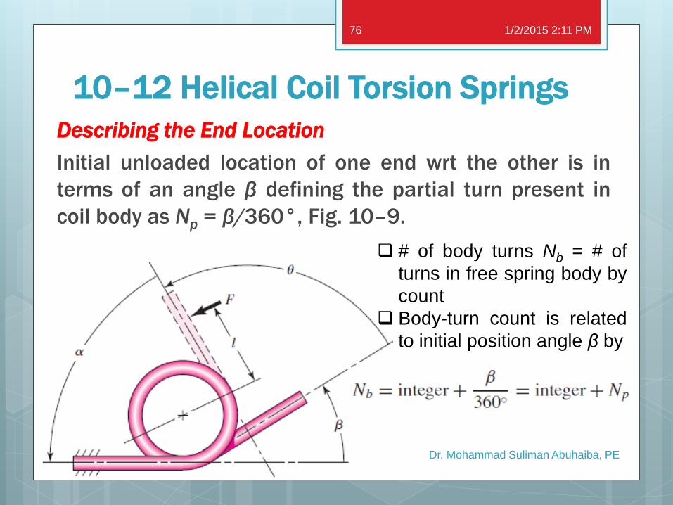
10–12 Helical Coil Torsion Springs
Describing the End Location
Initial unloaded location of one end wrt the other is in
terms of an angle β defining the partial turn present in
coil body as Np = β/360°, Fig. 10–9.
1/2/2015 2:11 PM
Dr. Mohammad Suliman Abuhaiba, PE
76
# of body turns Nb = # of
turns in free spring body by
count
Body-turn count is related
to initial position angle β by
10–12 Helical Coil Torsion Springs
Bending Stress
A torsion spring has bending induced in the
coils, rather than torsion.
Residual stresses built in during winding are in
same direction but of opposite sign to working
stresses that occur during use.
The strain-strengthening locks in residual
stresses opposing working stresses provided
the load is always applied in the winding sense.
1/2/2015 2:11 PM
Dr. Mohammad Suliman Abuhaiba, PE
77
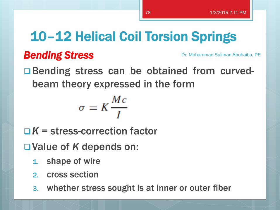
10–12 Helical Coil Torsion Springs
Bending Stress
Bending stress can be obtained from curved-
beam theory expressed in the form
K = stress-correction factor
Value of K depends on:
1. shape of wire
2. cross section
3. whether stress sought is at inner or outer fiber
1/2/2015 2:11 PM
Dr. Mohammad Suliman Abuhaiba, PE
78
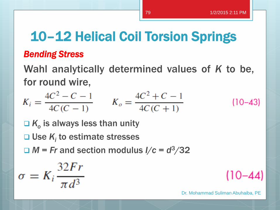
10–12 Helical Coil Torsion Springs
Bending Stress
Wahl analytically determined values of K to be,
for round wire,
Ko is always less than unity
Use Ki to estimate stresses
M = Fr and section modulus I/c = d3/32
1/2/2015 2:11 PM
Dr. Mohammad Suliman Abuhaiba, PE
79
10–12 Helical Coil Torsion Springs
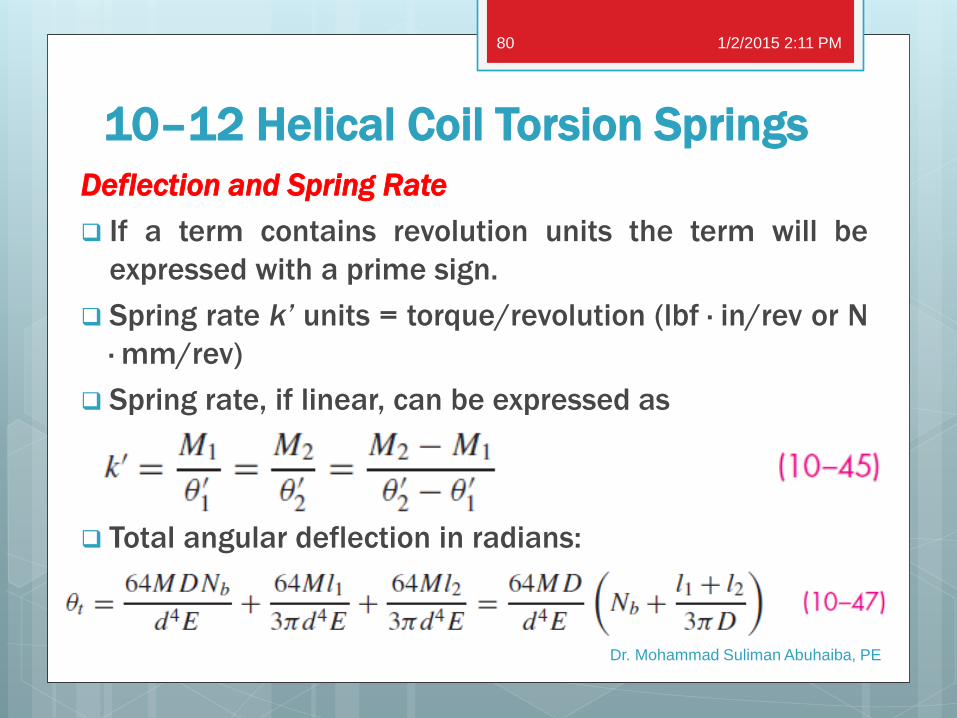
Deflection and Spring Rate
If a term contains revolution units the term will be
expressed with a prime sign.
Spring rate k’ units = torque/revolution (lbf · in/rev or N
· mm/rev)
Spring rate, if linear, can be expressed as
Total angular deflection in radians:
1/2/2015 2:11 PM
Dr. Mohammad Suliman Abuhaiba, PE
80
10–12 Helical Coil Torsion Springs
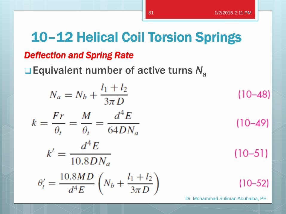
Deflection and Spring Rate
Equivalent number of active turns Na
1/2/2015 2:11 PM
Dr. Mohammad Suliman Abuhaiba, PE
81
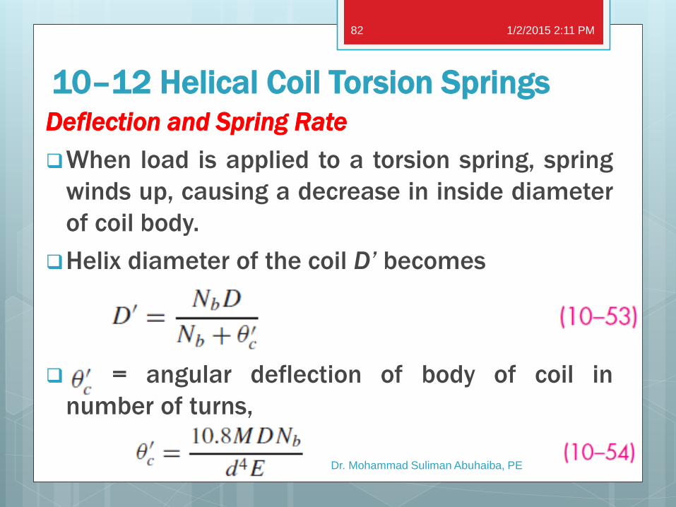
10–12 Helical Coil Torsion Springs Deflection and Spring Rate
When load is applied to a torsion spring, spring
winds up, causing a decrease in inside diameter
of coil body.
Helix diameter of the coil D’ becomes
= angular deflection of body of coil in
number of turns,
1/2/2015 2:11 PM
Dr. Mohammad Suliman Abuhaiba, PE
82
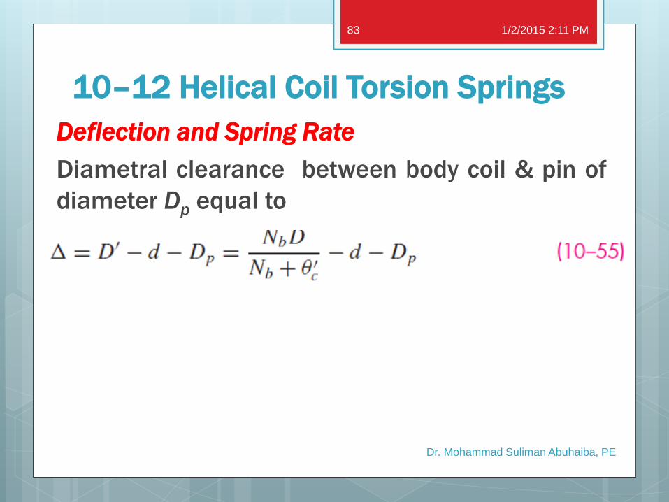
10–12 Helical Coil Torsion Springs
Deflection and Spring Rate
Diametral clearance between body coil & pin of
diameter Dp equal to
1/2/2015 2:11 PM
Dr. Mohammad Suliman Abuhaiba, PE
83
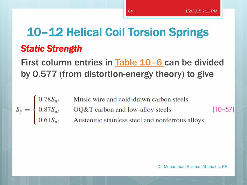
10–12 Helical Coil Torsion Springs
Static Strength
First column entries in Table 10–6 can be divided
by 0.577 (from distortion-energy theory) to give
1/2/2015 2:11 PM
Dr. Mohammad Suliman Abuhaiba, PE
84
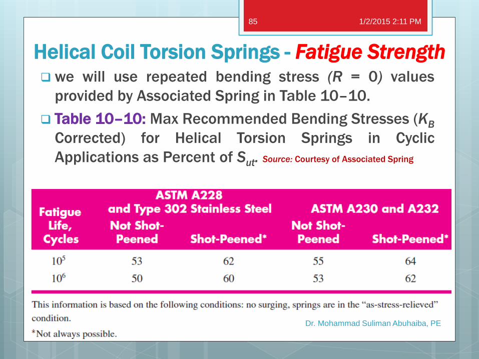
Helical Coil Torsion Springs - Fatigue Strength we will use repeated bending stress (R = 0) values
provided by Associated Spring in Table 10–10.
Table 10–10: Max Recommended Bending Stresses (KB
Corrected) for Helical Torsion Springs in Cyclic
Applications as Percent of Sut. Source: Courtesy of Associated Spring
1/2/2015 2:11 PM
Dr. Mohammad Suliman Abuhaiba, PE
85
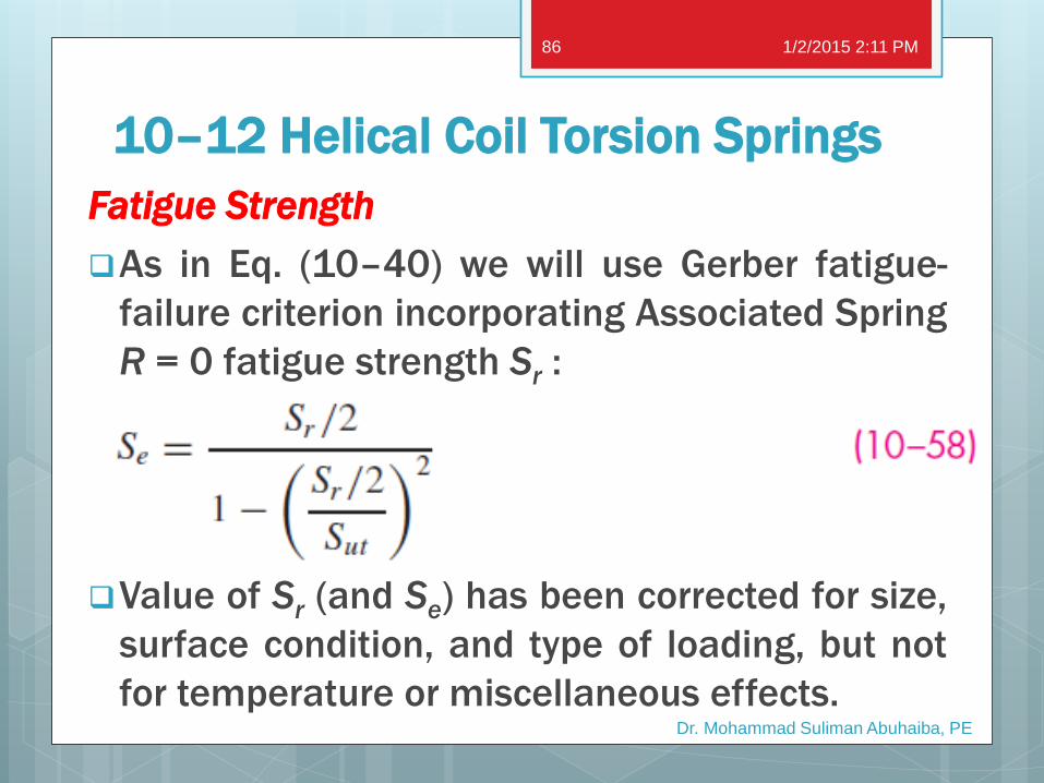
10–12 Helical Coil Torsion Springs
Fatigue Strength
As in Eq. (10–40) we will use Gerber fatigue-
failure criterion incorporating Associated Spring
R = 0 fatigue strength Sr :
Value of Sr (and Se) has been corrected for size,
surface condition, and type of loading, but not
for temperature or miscellaneous effects.
1/2/2015 2:11 PM
Dr. Mohammad Suliman Abuhaiba, PE
86
10–12 Helical Coil Torsion Springs
Fatigue Strength
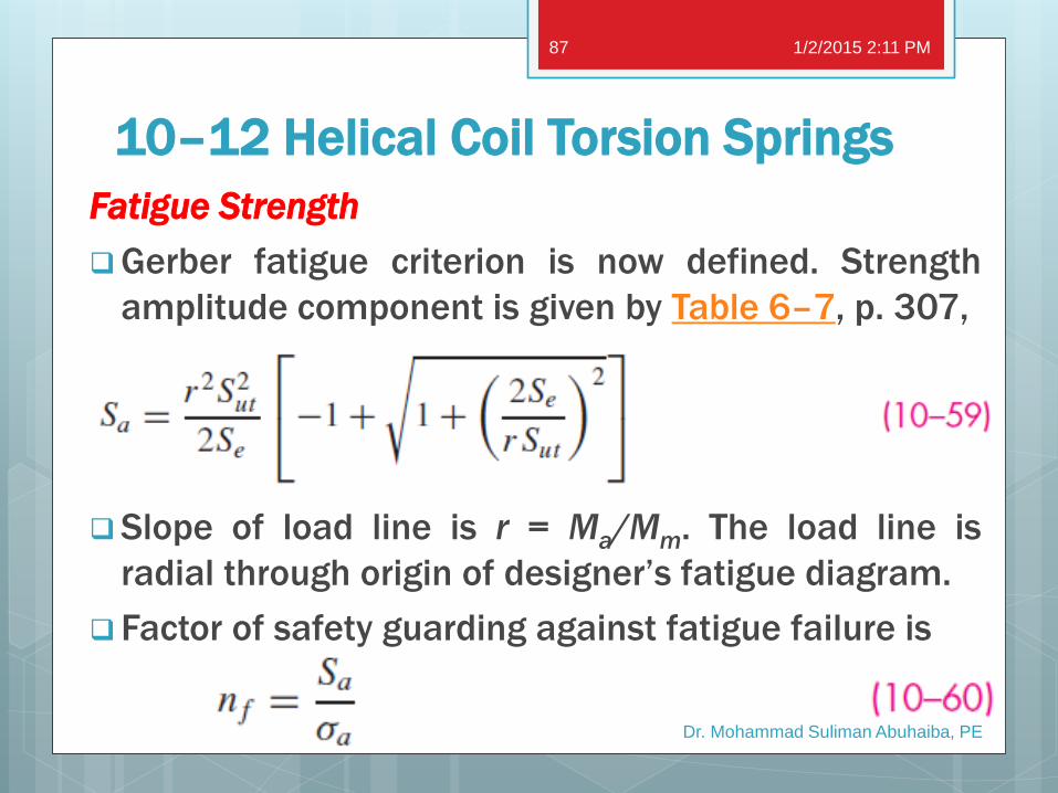
Gerber fatigue criterion is now defined. Strength
amplitude component is given by Table 6–7, p. 307,
Slope of load line is r = Ma/Mm. The load line is
radial through origin of designer’s fatigue diagram.
Factor of safety guarding against fatigue failure is
1/2/2015 2:11 PM
Dr. Mohammad Suliman Abuhaiba, PE
87
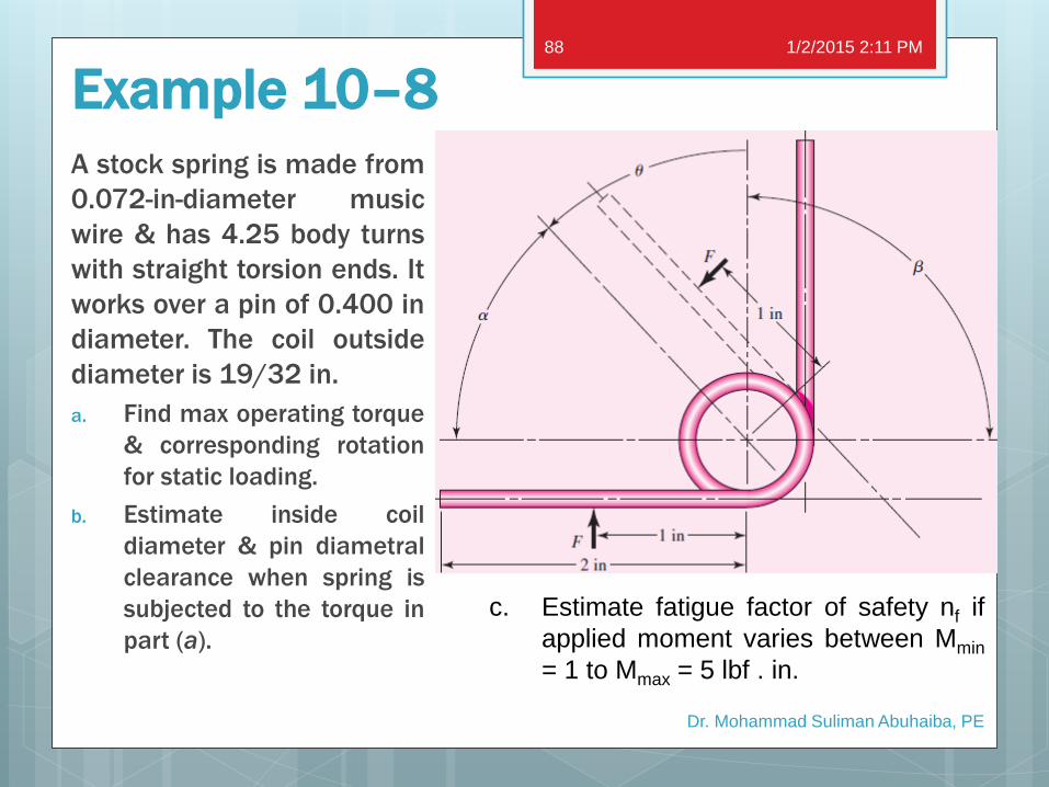
Example 10–8
A stock spring is made from
0.072-in-diameter music
wire & has 4.25 body turns
with straight torsion ends. It
works over a pin of 0.400 in
diameter. The coil outside
diameter is 19/32 in.
a. Find max operating torque
& corresponding rotation
for static loading.
b. Estimate inside coil
diameter & pin diametral
clearance when spring is
subjected to the torque in
part (a).
1/2/2015 2:11 PM
Dr. Mohammad Suliman Abuhaiba, PE
88
c. Estimate fatigue factor of safety nf if
applied moment varies between Mmin
= 1 to Mmax = 5 lbf . in.
Practice Problems
General Problems
3, 7, 20, 23, 25, 28, 36, 39
Design & Programming Problems
30 & 44
37 & 45
1/2/2015 2:11 PM
Dr. Mohammad Suliman Abuhaiba, PE
89