challenges and advances in welding of a new generation...
TRANSCRIPT

Challenges and Advances in Welding of a New Generation of
High Strength Steels
Presented by T. V. Natale (AK Steel) Written by M. Kimchi (OSU), W. Peterson (EWI), J. Gould (EWI)

CAFE Standard: 54.5 MPG in 2025
New CAFE Standards2012-2016 and 2017-2025
MASS REDUCTION
AISI, www.autosteel.org, 2012

(auto/steel partnership)
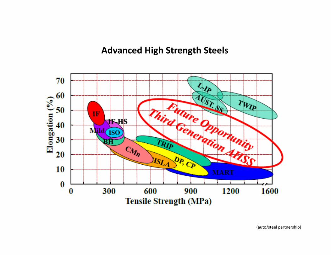
Advanced High Strength Steels

(WorldAutoSteel 2011)
Future Steel Vehicle – Phase 2

2013 Ford Escape
(Morgans, GDIS 2013)
(WorldAutoSteel 2011)
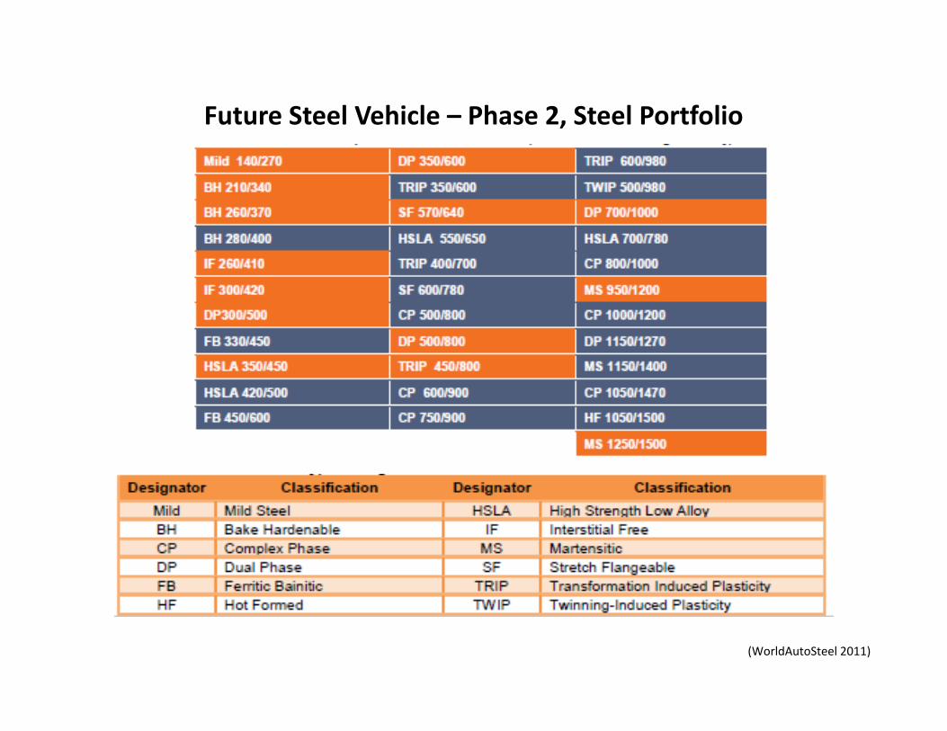
Future Steel Vehicle – Phase 2, Steel Portfolio
(WorldAutoSteel 2011)
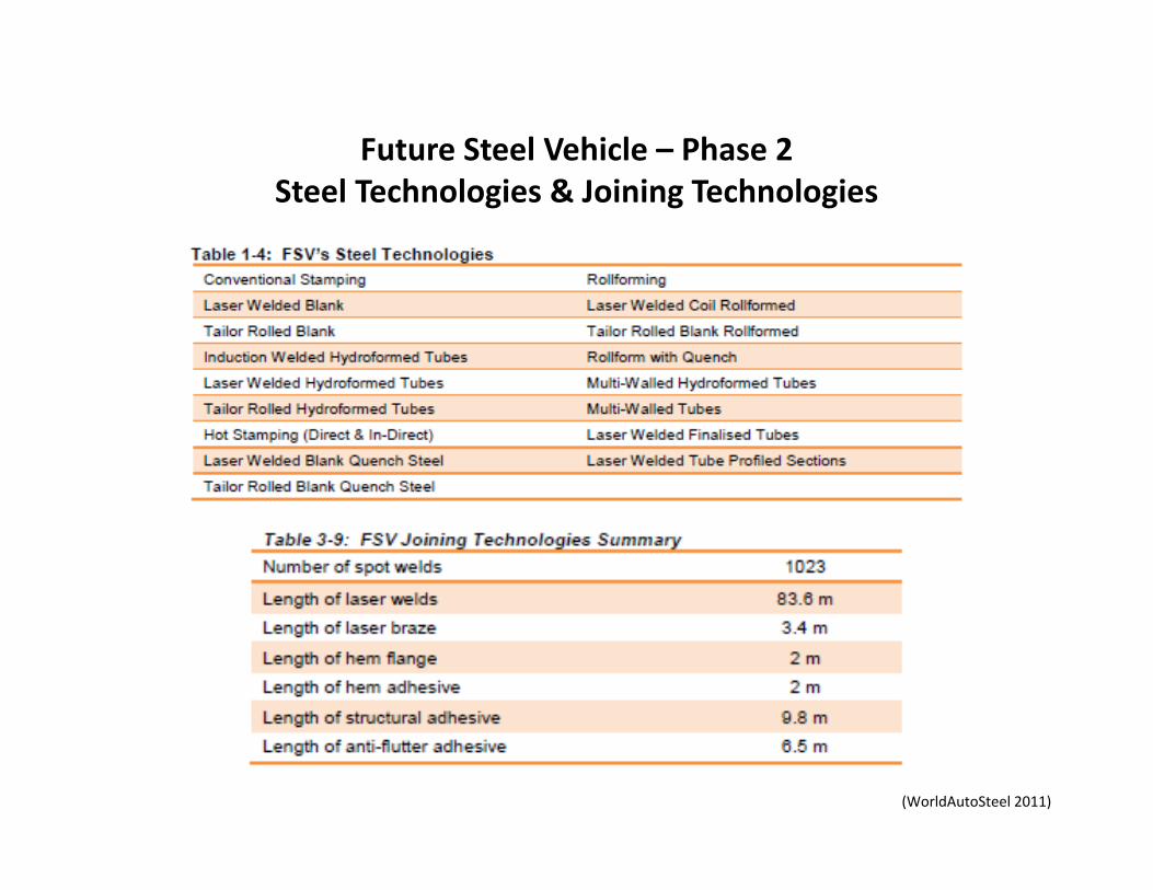
Future Steel Vehicle – Phase 2Steel Technologies & Joining Technologies
(auto/steel partnership)
Advanced High Strength Steels

(Branagan, GDIS 2013)
AHSS Developments

(Branagan, GDIS 2013)
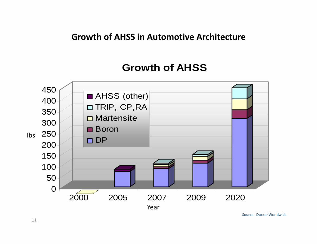
Growth of AHSS in Automotive Architecture
11
050
100150200250300350400450
2000 2005 2007 2009 2020
Growth of AHSS
AHSS (other)TRIP, CP,RAMartensiteBoronDPlbs
YearSource: Ducker Worldwide
Resistance Spot WeldingAdvanced High Strength Steels AHSS
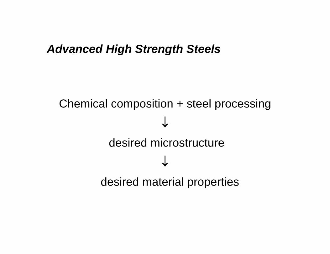
Chemical composition + steel processing
desired microstructure
desired material properties
Resistance Spot WeldingAdvanced High Strength Steels AHSS
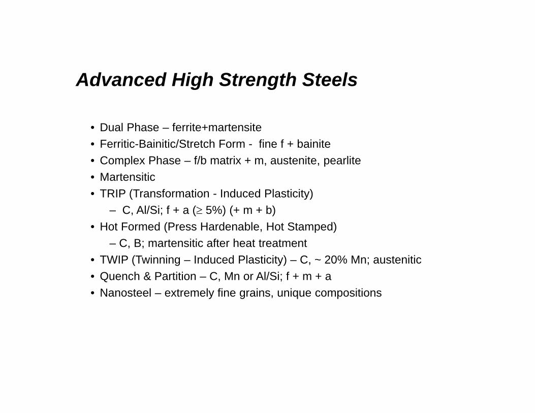
• Dual Phase – ferrite+martensite• Ferritic-Bainitic/Stretch Form - fine f + bainite• Complex Phase – f/b matrix + m, austenite, pearlite• Martensitic• TRIP (Transformation - Induced Plasticity)
– C, Al/Si; f + a ( 5%) (+ m + b)• Hot Formed (Press Hardenable, Hot Stamped)
– C, B; martensitic after heat treatment• TWIP (Twinning – Induced Plasticity) – C, ~ 20% Mn; austenitic• Quench & Partition – C, Mn or Al/Si; f + m + a• Nanosteel – extremely fine grains, unique compositions

[Referen
ce: Re
sistance Welding
Man
ual, RW
MA, p. 1
‐3]
Principal Types of Resistance Welds
Electrodes orWelding Wheels
Seam Weld
Electrodes or Welding Tips
Spot Weld
Electrodes or Dies
Projection WeldAfter Welding
Electrodes or Dies
Butt Weld
Flash Weld
After WeldingHigh‐Frequency Weld

Resistance Spot WeldingResistance Spot Welding AHSSHSLA and AHSS
• Increased electrical resistivity• Heat balance• As strength , composition , and thickness , more
pronounced changes in welding behavior occur. • Increased force and longer welds times typical• Increased weld hardness• Weld fracture modes• Pulsation and/or post weld tempering• Joint fatigue, fracture, stress concentration, crash integrity,
modeling

Cooling Rate as a Function of Gauge, Steel and Welding Process
• Implied cooling rates for different processes– Closed‐form models
• Critical cooling rates– Martensite transformation– Microstructural modeling
• Hardenability of AHSS• Martensite formation
resulting from welding• Hardness of martensite/
effective fracture toughness
10
100
1000
10000
100000
0 0.5 1 1.5 2 2.5
Sheet Thickness (mm)
Coo
ling
Rat
e (C
o /s)
GMAWLBWRMSWRSWIF
AKDQ
M1400
TRIP 600
DP 980
TRIP 800
DP 600
DP 780
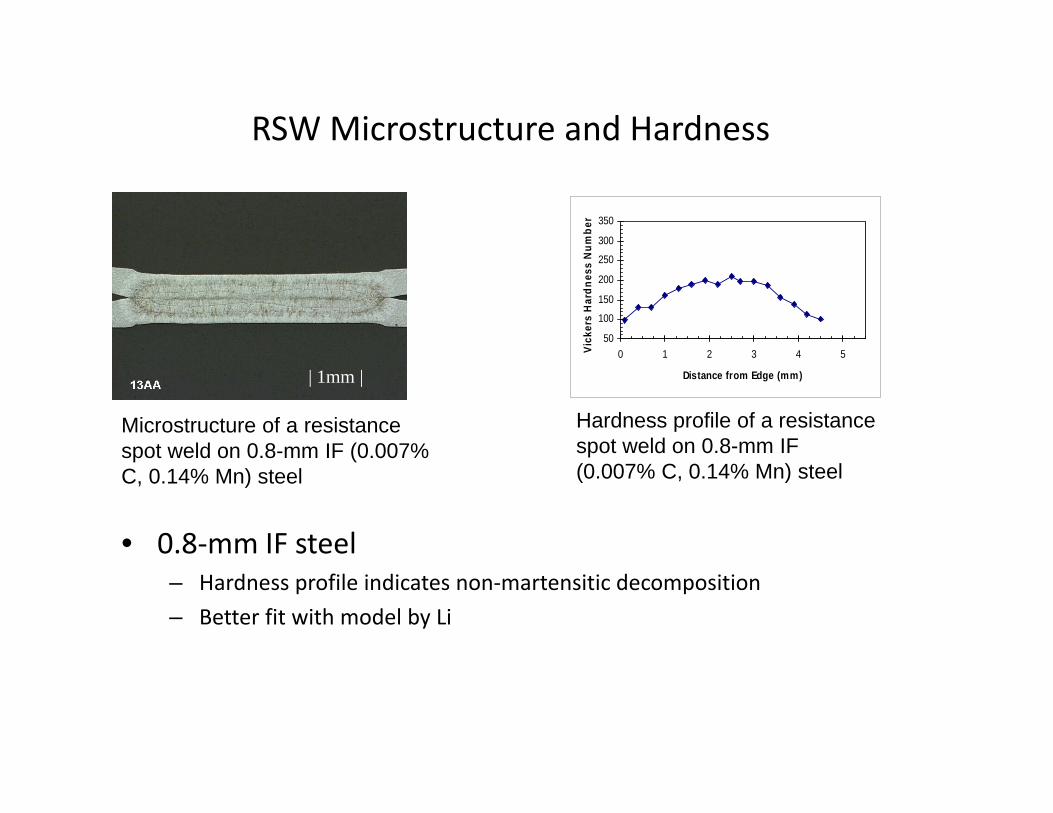
RSW Microstructure and Hardness
• 0.8‐mm IF steel– Hardness profile indicates non‐martensitic decomposition– Better fit with model by Li
50
100
150
200
250
300
350
0 1 2 3 4 5
Distance from Edge (mm)
Vick
ers
Har
dnes
s N
umbe
r
| 1mm |
Microstructure of a resistance spot weld on 0.8-mm IF (0.007% C, 0.14% Mn) steel
Hardness profile of a resistance spot weld on 0.8-mm IF (0.007% C, 0.14% Mn) steel

• 1.6‐mm DP 980– “Top Hat” hardness profile– Indicative of isothermal transformation– Martensitic reaction predicted by either model
200.0
250.0
300.0
350.0
400.0
450.0
500.0
0 2 4 6 8 10 12 14 16 18 20 22 24
Location (mm)
Microstructure of a resistance spot weld on 1.6-mm DP980 (0.15% C, 1.4% Mn) steel
Microstructure of a resistance spot weld on 1.6-mm DP980 (0.15% C, 1.4% Mn) steel
RSW Microstructure and Hardness
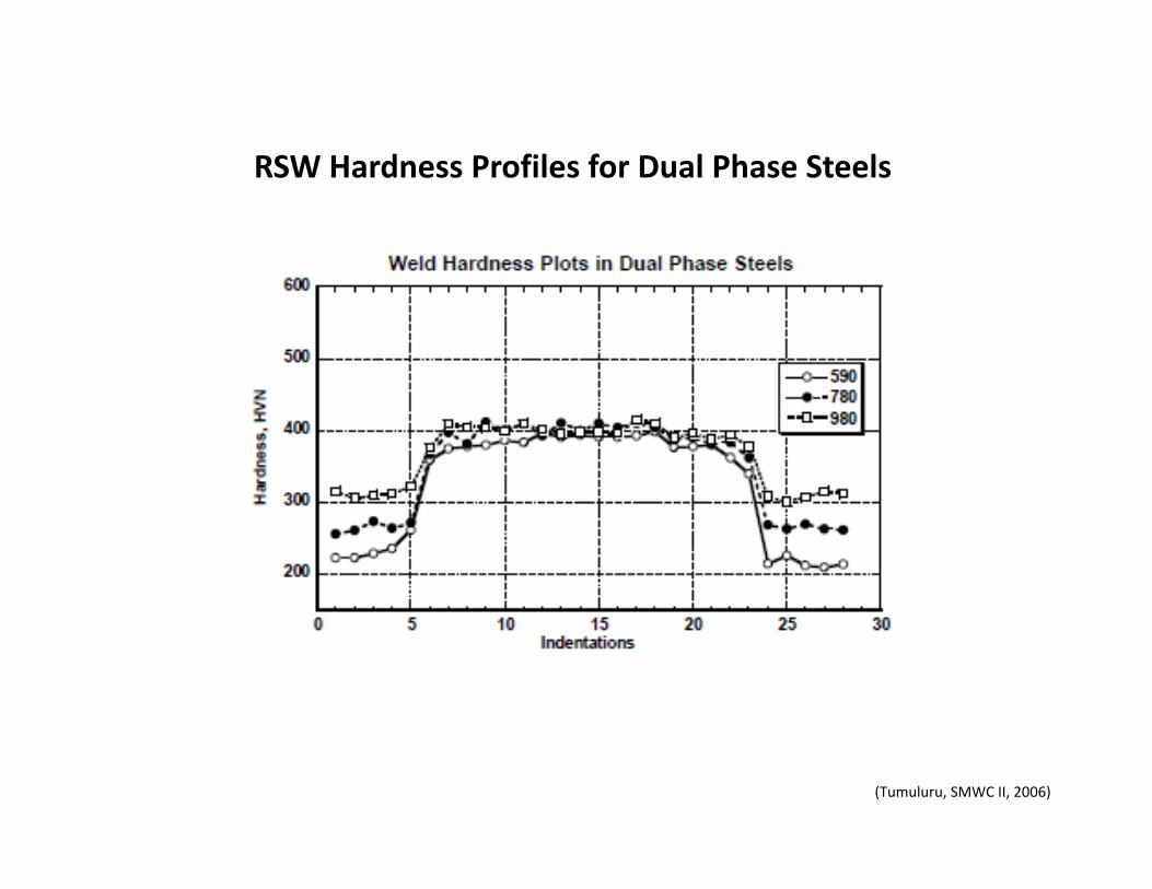
(Tumuluru, SMWC II, 2006)
RSW Hardness Profiles for Dual Phase Steels
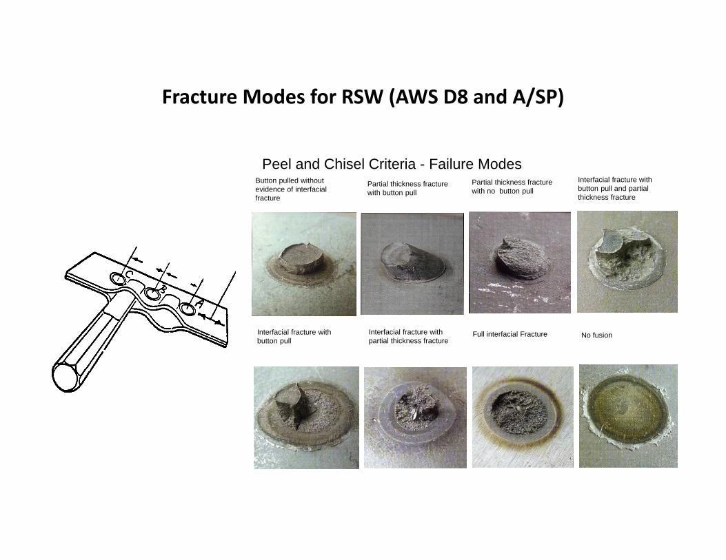
Fracture Modes for RSW (AWS D8 and A/SP)
Peel and Chisel Criteria - Failure ModesButton pulled without evidence of interfacial fracture
Partial thickness fracture with button pull
Partial thickness fracture with no button pull
Interfacial fracture with button pull and partial thickness fracture
Full interfacial Fracture No fusionInterfacial fracture with button pull
Interfacial fracture with partial thickness fracture

Potential Solutions to Improving Peel Behaviorof AHSS Spot Welds
• Passive methods– Long weld time– Pre/post pulsing– Short hold time– Increased minimum weld size
• Active methods– Weld and temper– Dilution (patented)
WeldDown Slope Quench Temper Hold
Electrode Force
Dilution Weld

(WorldAutoSteel 2009)
Force and Current Profiles for RSW of AHSS
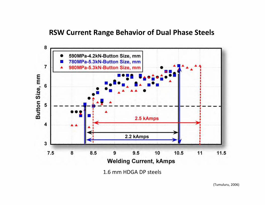
(Tumuluru, 2006)
1.6 mm HDGA DP steels
RSW Current Range Behavior of Dual Phase Steels
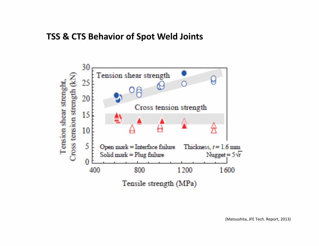
(Matsushita, JFE Tech. Report, 2013)
TSS & CTS Behavior of Spot Weld Joints

Tensile Shear Strength of High‐Strength Steels vs. Thickness

Static‐Cross Tension Strength of HSS vs. Carbon, Thickness
W/2
W L
WELD IS CENTERED
HS
20 mm; +0.2,- 0
AT W/2 AND L/2

Effect of Fracture Appearance on Absorbed Energy
0 50
100
200
300400
500
600
Fracture Appearance Rating
Ene
rgy
(in-lb
f)
Tensile Shear Test
0 1 3 4 50
100200300400500600
Fracture Appearance Rating
Ene
rgy
(in-lb
f)
Dynamic Cross Tension Test

Effect of Steel Strength on Peak Load in Weld Cross‐Tension Impact Behavior of RSW
Cracking

Cracking
Effect of Steel Strength on Absorbed Energy in Weld Cross‐Tension Impact Behavior of RSW

Temper Diagram for 0.9 mm DP980
General Characteristics of In‐Situ Tempering of Spot Welds
• Overall J‐shaped curve• Two distinct regions
– Steady state– Transient
• (Short time, high current)
• Correlations between hardness and weld failure morphology
Temper Time (cycles)0 50 100 150 200
0
20
40
60
80
100
120
140
30 Rc32 Rc34 Rc36 Rc38 Rc40 Rc42 Rc
024 8 16 32 64 128 200
0
5
10
15
20
25
30
35
40
45
50
55
60
65
70
75
80
85
90
95
100
105
110
115
120
125
130
135
140
Button Peel Interfacial Failures
0 16 32
656565
Zero, Mid, Full Temper Locations
Tem
per C
urre
nt (%
Exp
ulsi
on L
imit)
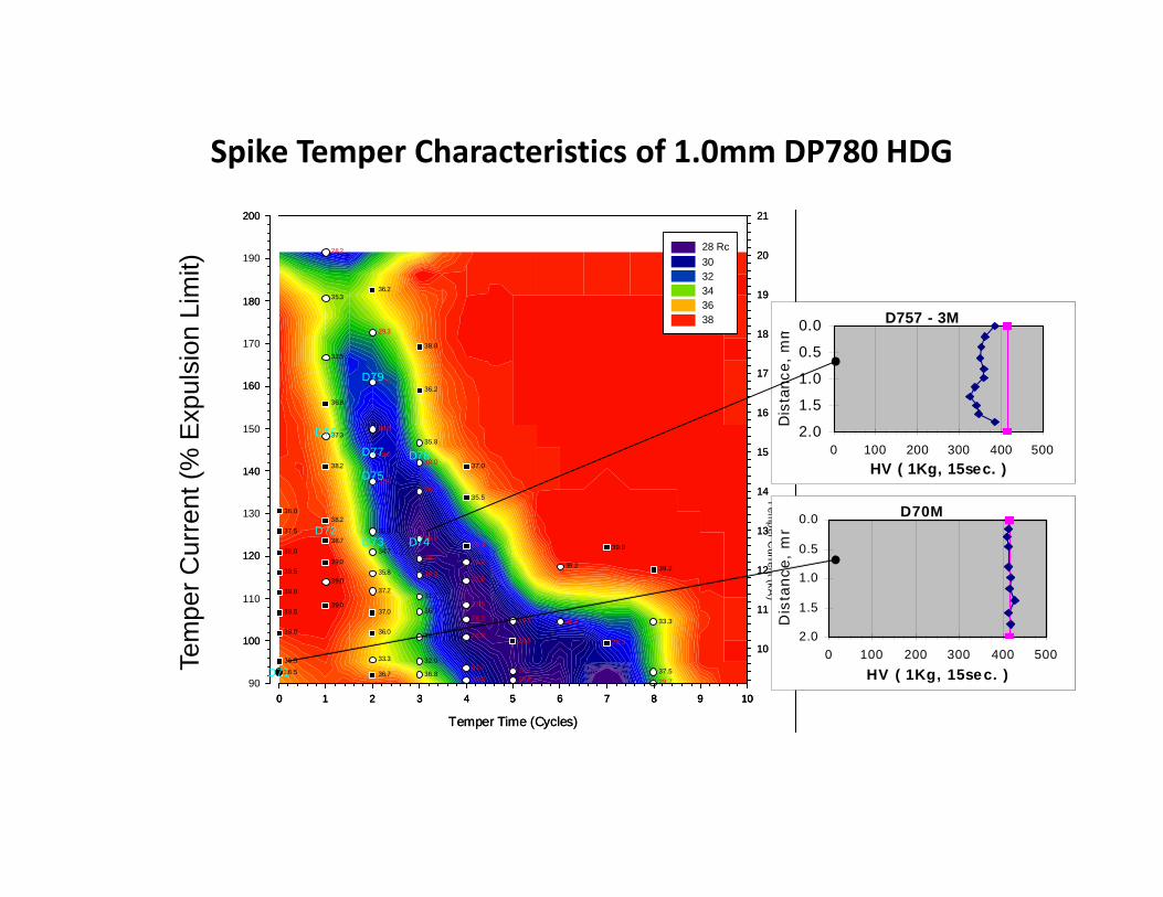
Spike Temper Characteristics of 1.0mm DP780 HDG
Temper Time (Cycles)
0 1 2 3 4 5 6 7 8 9 1090
100
110
120
130
140
150
160
170
180
190
200
28 Rc30 32 34 36 38
Temper Time (Cycles)
0 1 2 3 4 5 6 7 8 9 10
100
120
140
160
180
200
Tem
per Current (kA
)
10
11
12
13
14
15
16
17
18
19
20
21
29.730.0 26.836.7 36.836.5 37.530.731.7
36.5 32.033.3
28.326.531.7 28.036.038.0
31.2 33.329.328.237.038.5 36.7
39.0 27.531.739.0 37.2
39.0 27.530.535.839.5 39.239.239.0 29.228.7
34.738.0 39.029.338.7 26.732.237.5
38.236.0
35.526.8
32.0
38.2 37.030.028.0
35.837.3
26.8
36.8
36.227.3
33.538.8
29.3
35.336.2
28.2
0 1 2 3 4 5 6 7 8 9 10
10
11
12
13
14
15
16
17
18
19
20
21
D71
D72D73 D74
D75
D76
D77 D78
D79
D70M0.0
0.5
1.0
1.5
2.00 100 200 300 400 500
HV ( 1Kg, 15sec. )
Dis
tanc
e, m
m
D757 - 3M0.0
0.5
1.0
1.5
2.00 100 200 300 400 500
HV ( 1Kg, 15sec. )
Dis
tanc
e, m
m
Temper Time (Cycles)
0 1 2 3 4 5 6 7 8 9 1090
100
110
120
130
140
150
160
170
180
190
200
28 Rc30 32 34 36 38
Temper Time (Cycles)
0 1 2 3 4 5 6 7 8 9 10
100
120
140
160
180
200
Tem
per Current (kA
)
10
11
12
13
14
15
16
17
18
19
20
21
29.730.0 26.836.7 36.836.5 37.530.731.7
36.5 32.033.3
28.326.531.7 28.036.038.0
31.2 33.329.328.237.038.5 36.7
39.0 27.531.739.0 37.2
39.0 27.530.535.839.5 39.239.239.0 29.228.7
34.738.0 39.029.338.7 26.732.237.5
38.236.0
35.526.8
32.0
38.2 37.030.028.0
35.837.3
26.8
36.8
36.227.3
33.538.8
29.3
35.336.2
28.2
0 1 2 3 4 5 6 7 8 9 10
10
11
12
13
14
15
16
17
18
19
20
21
D71
D72D73 D74
D75
D76
D77 D78
D79
D70M0.0
0.5
1.0
1.5
2.00 100 200 300 400 500
HV ( 1Kg, 15sec. )
Dis
tanc
e, m
m
D757 - 3M0.0
0.5
1.0
1.5
2.00 100 200 300 400 500
HV ( 1Kg, 15sec. )
Dis
tanc
e, m
m
Tem
per C
urre
nt (%
Exp
ulsi
on L
imit)
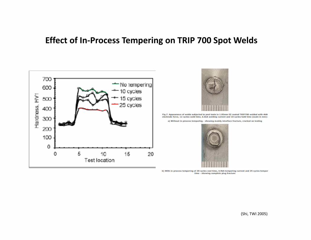
(Shi, TWI 2005)
Effect of In‐Process Tempering on TRIP 700 Spot Welds

(WorldAutoSteel 2009)
Tensile Shear Fatigue Behavior of Steel Spot Welds
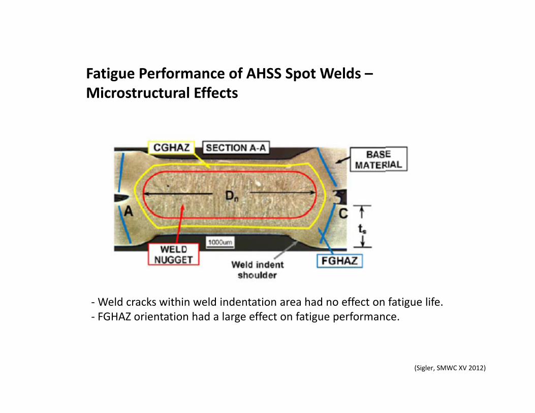
(Sigler, SMWC XV 2012)
‐Weld cracks within weld indentation area had no effect on fatigue life.‐ FGHAZ orientation had a large effect on fatigue performance.
Fatigue Performance of AHSS Spot Welds –Microstructural Effects
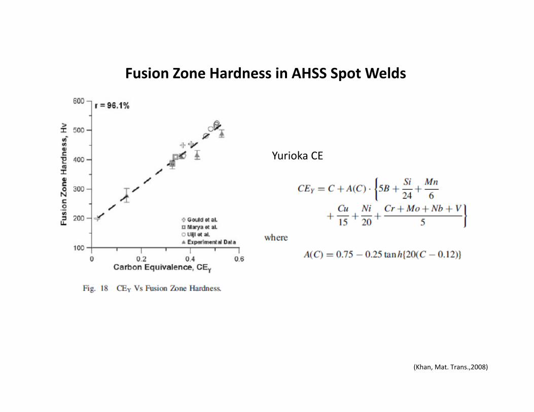
Yurioka CE
(Khan, Mat. Trans.,2008)
Fusion Zone Hardness in AHSS Spot Welds

(den Uijl, WiW 2008)

Resistance Butt Welding of AHSS
• Steel grades commonly resistance butt welded
– 600 MPa– 800 MPa– 1000 MPa
• Process requirements– Short cycle times– High currents– Fast reacting force systems
• Metallurgical response– Constrained heat affected zones– Minimized extent of HAZ softening– Mechanical constraint to provide
properties• Effect of parent material strength• Typical scrap levels today for AHSS:
0.2 – 2%
Developing temperature distribution during resistance butt welding mild steel
Distribution of effective strain through a cross section of a resistance butt welded mild steel

(WorldAutoSteel 2009)
Weld hardness of a high frequency weld in a DP 280/600 tube.

(WorldAutoSteel 2009)
Hardness variation across induction welds for various types of steel
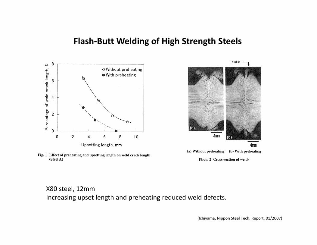
(Ichiyama, Nippon Steel Tech. Report, 01/2007)
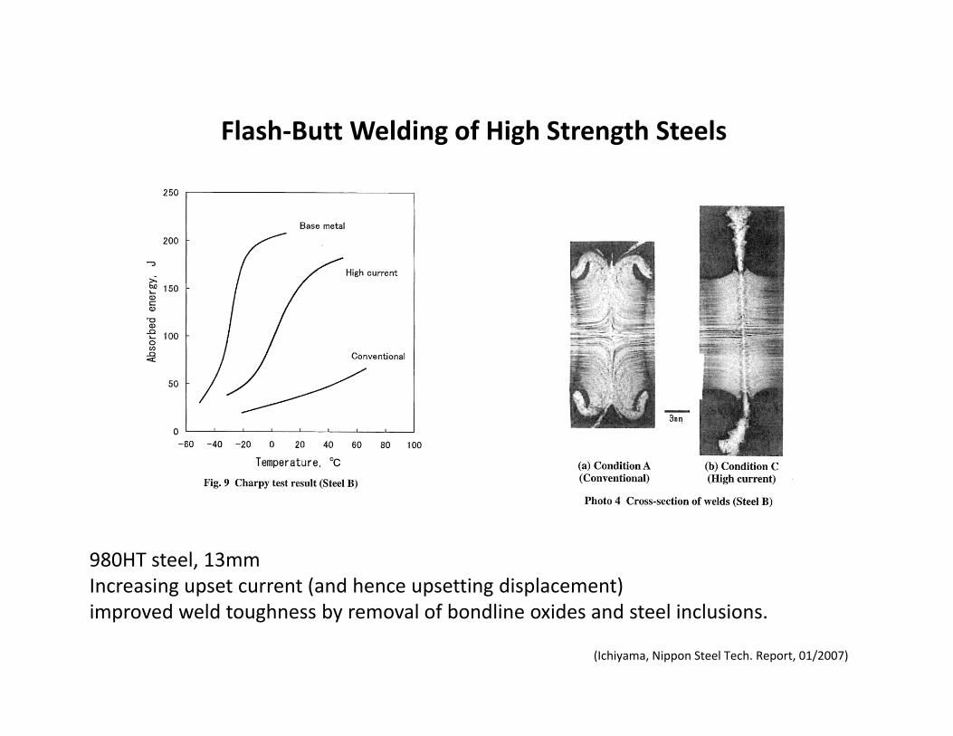
Flash‐Butt Welding of High Strength Steels
X80 steel, 12mmIncreasing upset length and preheating reduced weld defects.
(Ichiyama, Nippon Steel Tech. Report, 01/2007)
Flash‐Butt Welding of High Strength Steels
980HT steel, 13mmIncreasing upset current (and hence upsetting displacement)improved weld toughness by removal of bondline oxides and steel inclusions.

(Biro, SMWC XV, 2012)
Higher than Expected Strengths from Dissimilar ConfigurationAdvanced High Strength Steel Spot Welds
Example of dissimilar configuration with CTS matching the “minimum rule”
For AHSS/AHSS configurations, cross‐tension strength is always higherthan the strength expected from the lower strength material in the joint.
Cross‐tension strength for TRIP800configurations, showing “positive deviation”
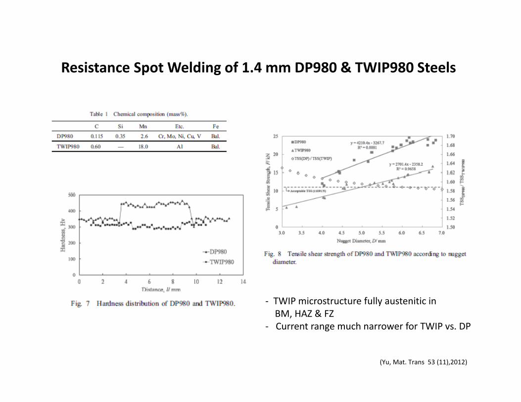
(Yu, Mat. Trans 53 (11),2012)
Resistance Spot Welding of 1.4 mm DP980 & TWIP980 Steels
‐ TWIP microstructure fully austenitic inBM, HAZ & FZ
‐ Current range much narrower for TWIP vs. DP
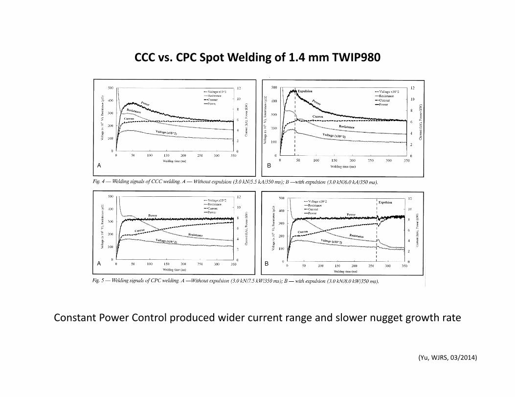
(Yu, WJRS, 03/2014)
CCC vs. CPC Spot Welding of 1.4 mm TWIP980
Constant Power Control produced wider current range and slower nugget growth rate
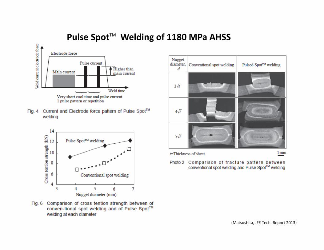
(Matsushita, JFE Tech. Report 2013)
Pulse SpotTM Welding of 1180 MPa AHSS
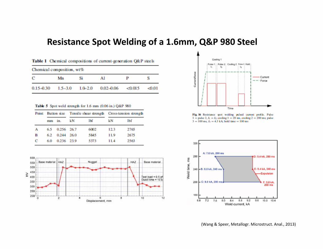
Resistance Spot Welding of a 1.6mm, Q&P 980 Steel
(Wang & Speer, Metallogr. Microstruct. Anal., 2013)

(den Uijl, Tata Steel online report)
HSLA 300, 2.2 mm
DP800 GI, 1.6 mm
IF GI, 0.8mm
Resistance spot welding of a complicated joint in newadvanced high strength steel