certificate 2957 revision 2 - gov.uk › government › uploads › syst… · drink command...
TRANSCRIPT

Issue Date: Valid Until: Reference No:
G Stones Technical Manager - Certification ServicesFor and on behalf of the Chief Executive
National Measurement and Regulation Office | Stanton Avenue | Teddington | TW11 0JZ | United KingdomTel +44 (0)20 8943 7272 | Fax +44 (0)20 8943 7270 | Web www.gov.uk/nmro
The NMRO is an Executive Agency of the Department for Business Innovation & Skills
Pursuant to section 12 ofthe Weights and Measures Act 1985
Certificate No 2957
issued by: The National Measurement
In accordance with the provisions of 1985, the Secretary of State for Business, Innovation & Skills has issued this UK national type-approval certificate to: Drink Command Limited The Arena, Stockley ParkUxbridge London UB11 1AA
and hereby certifies as suitable for use for tintoxicating liquor instrument, in respect of fixed quantities of either characteristics, alterations, securing, functioningconditions (when applicable) are set out in the descriptive annex to this certificate.
Note: This certificate relates to the suitability of the equipment for use for trade only in respect of its metrological characteristics. It does not constitute or imply any guarantee as to the safety of the equipment in use for trade or otherwise.
This revision replaces previous versions of the certificate.
15 May 2015 30 December 2023 TS0502/0006
Certification Services For and on behalf of the Chief Executive
National Measurement and Regulation Office | Stanton Avenue | Teddington | TW11 0JZ | United KingdomTel +44 (0)20 8943 7272 | Fax +44 (0)20 8943 7270 | Web www.gov.uk/nmro
The NMRO is an Executive Agency of the Department for Business Innovation & Skills
Pursuant to section 12 of the Weights and Measures Act 1985
2957 Revision 2
The National Measurement and Regulation Office
the provisions of section 12 of the Weights and Measures Act 1985, the Secretary of State for Business, Innovation & Skills has issued this UK
approval certificate to:
The Arena, Stockley Park
hereby certifies as suitable for use for trade the following pattern of an instrument, in respect of a beer measuring system dispensing
either half pint or pint. The necessary data (principal tions, securing, functioning etc) for identification purposes and
conditions (when applicable) are set out in the descriptive annex to this certificate.
Note: This certificate relates to the suitability of the equipment for use for trade only its metrological characteristics. It does not constitute or imply any
guarantee as to the safety of the equipment in use for trade or otherwise.
This revision replaces previous versions of the certificate.
2957
III(2)
National Measurement and Regulation Office | Stanton Avenue | Teddington | TW11 0JZ | United Kingdom
The NMRO is an Executive Agency of the Department for Business Innovation & Skills
section 12 of the Weights and Measures Act 1985, the Secretary of State for Business, Innovation & Skills has issued this UK
rade the following pattern of an a beer measuring system dispensing
The necessary data (principal etc) for identification purposes and
conditions (when applicable) are set out in the descriptive annex to this certificate.
Note: This certificate relates to the suitability of the equipment for use for trade only its metrological characteristics. It does not constitute or imply any
guarantee as to the safety of the equipment in use for trade or otherwise.

2
CONTENTS CERTIFICATION NO 2957
2 CONSTRUCTION
2.1 General 2.2 Mechanical 2.3 Electrical 2.4 Electronics 2.5 Interlocks 2.6 Legends 2.7 Securing (sealing) 2.8 EMC requirements
3 OPERATION
3.1 System set-up 3.2 Software 3.3 Dispensing
4 AUTHORISED ALTERNATIVES
5 RECOMMENDED TESTS 5.1 Accuracy 5.2 Interlocks 5.3 Labels and markings 5.4 Securing
6 ILLUSTRATIONS 7 CERTIFICATE HISTORY

3
CERTIFICATION NO 2957
Descriptive Annex 1 INTRODUCTION This liquid measuring instrument is for use in dispensing measured nominal quantities of ½ pint and 1 pint of beer, stout or cider by specifying the required volume on a touch sensitive button directly below am Liquid Crystal Display (LCD) panel. A pre-programmed user-controlled magnetic key fob (i-Button) is used to authorise use of a dispense. A dispense is initiated by pulling a tap lever forward. Communication of information is passed between the instrument and a remote controller box via a Radio Frequency (RF) connection. The manufacturer’s model designation for this instrument is The Draft Beer Table. The instrument has two dispense points, independently controlled by dedicated flow meters and electronically operated solenoid valves. Satisfactory dispensing requires that the temperature of the liquid to be within the range of 4 - 6 degrees Celsius at a head pressure of 1.6 Bar. 2 CONSTRUCTION
2.1 General
2.1.1 A mobile self-pouring dispensing unit, consisting of a 130 cm diameter wood effect round table containing two independently operated tap dispensers located on a central tower capable of 320 degree rotation and surrounded by a circular drip tray. 2.1.2 Below the table top is a metal casing containing two separate compartments. One side called “Wet Side”, which houses two standard sized beer kegs. The opposite side, called “Dry side”, houses two gas cylinders a cooling unit and the electronics/controller box. Both compartments have lockable doors. Mobility is provided by wheels and/or casters. 2.1.3 Each dispense tap is supplied by a 3/8” pipe from the keg, this is reduced down to 5/16” for a stout after the flow meter and solenoid valve up to the dispense tower. There is a diffuser on the end of the stout tap. The lager keg pipe diameter is reduced down to 3/16” after the flow meter and solenoid valve up to the dispense tower. 2.2 Mechanical
2.2.1 Each keg is connected to a Froth on Beer (FOB) detector, which has a manual float positioning lever. This connects in-line to the flow meter and solenoid valve to the manually operated lever pull taps.
4
2.2.2 Each gas cylinder is connected to a pressure regulator, set at 1.6 bar. This feeds the correct pressure to the keg. After the beer/cider or stout leaves the keg it passes through a glycol-water filled cooling system set for the correct serving temperature required. 2.3 Electrical 2.3.1 The dispense table unit, including the cooler unit, is powered by a 230V 50Hz AC supply. This supplies power to the central tower, RF transceiver, the solenoid valve switches, flow meters, circuit boards and cooling system 2.3.2 The controller box is powered by a 12V 50Hz DC supply, which also feeds power to an LCD and RF transceiver box. 2.4 Electronics
2.4.1 The central tower houses an RF transceiver, two LCD panels, (one for each tap), a circuit board, four touch sensitive buttons, two for each tap, and two magnetic “i-Button” sensors, one for each tap. 2.4.2 The “Wet side” houses two commercially available solenoid valves and two commercially available flow meters model Titan 300-010 Beverage meters, one for each tap, and an electronic sump pump. 2.4.3 The “Dry side” houses the control circuit board. 2.4.4 The RF controller box contains an LCD, a magnetic card reader, i-Button place holder, circuit boards and memory card. An RF transceiver aerial is hardwired to the controller box.
2.5 Interlocks
2.5.1 The following interlocks will prevent the system from initiating a dispense:
• FOB detector activated.
• i-Button not seated, or incorrectly seated. No credit on i-Button
• Table “CLOSED” or “PAUSED” on display.
• No communication to or from the RF controller box.
2.5.2 The following interlocks will prevent further use after a full dispense has been completed.
• Measured flow rate below a specified threshold. “FLOW ERROR” and “CALL MANAGER” on LCD display
• Insufficient credit on i-Button
• FOB detector activated. “FLOW ERROR” and “CALL MANAGER” on LCD display.

5
2.5.3 The flow rate is monitored by software. The threshold is generously set in order to allow for a satisfactory and complete delivery of a specified quantity.
2.5.4 A satisfactory and accurate dispense is dependant on a correct head pressure setting. A specific pressure gauge/regulator is used that should be locked at 1.6 bar (± 0.1 bar) and sealed. See Figure 8.
2.6 Legends
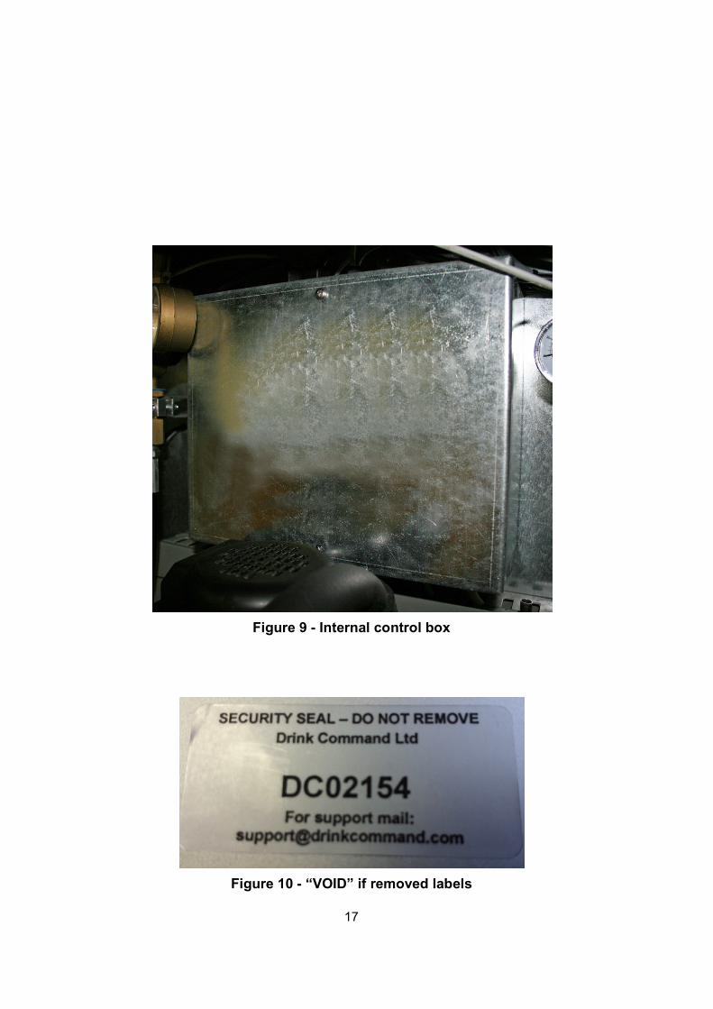
2.6.1 The following legends are marked, in the form of a fixed metallic plate or a label, which shall be destroyed/voided if removed.
• Manufacturer’s name : Drink Command Limited.
• The certificate number: 2957
• Specified quantity legend: 1 pint and ½ Pint
• Product Serial number
2.7 Securing (Sealing)
2.7.1 The following items are to be secured or sealed and are described as follows:
• Mixed gas cylinder head pressure - purpose built pressure gauge and regulator will be set, locked and sealed with a numbered tamper evident tie wrap. Fig 8.
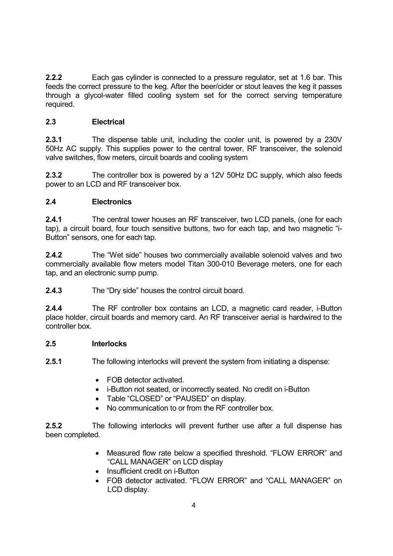
• Internal power/controller box, see Fig. 9 - controller box maintenance cover fitted with secure screws and/or “VOID” if removed stickers
• Remote RF controller box, see Fig. 6 - management control box housing fitted with secure screws and/or “VOID” if removed stickers
• Cabinet doors - key locks fitted. Doors locked when in service, keys are kept in a secure location.
• Chiller unit control pad - correct temperature set. Keypad locked, key code required for temperature adjustments.

6
2.7.2 The RF Management controller box software can only be accessed using magnetic swipe cards as described below:
• Technician Card, Fig 7 - in possession of a Drink Command Limited employee only. This card allows full access to all software parameters including the metrology algorithms. The system can be calibrated during the installation process only. This card is never left at the installation premises and any further adjustments can only be made by a Drink Command Limited employee, or their trained and approved regional service agent.
• Manager Card, Fig 7 - in possession of an employee at the installation premises. This card does not allow access to the metrology algorithms. This card is used to access to the following features:
a) Table states, i.e. “OPEN”, “CLOSED”, “PAUSED” b) Assigning table numbers c) Assigning table drink products d) Accessing usage reports e) Resetting tables displaying “FLOW ERROR” and “CALL
MANAGER”
• Operator Card, Fig 7 - in possession by employees at installed premises. This card does not allow access to the metrology algorithms or manager’s parameters. This card is used to charge the i-Button with credits to enable access for customers to the mobile or fixed draft beer table for the dispense of the prescribed quantities of intoxicating liquor.
2.7.3 The i-Button can be programmed with two different levels of access to the draft beer table and are described as follows:
• Resetting the table following a significant fault. Display will read “MANAGER PRESENT” when the i-Button is seated into the magnetic sensor. Can only be programmed using the Manager Card and is only in the possession of the employee who is responsible for the Manager Card.
• Initiating a prescribed quantity dispense. Can be programmed using Manager Card or Bar staff Card. This i-Button is in the possession of the customer.

7
2.8 EMC requirements
2.8.1 A mains filter fitted in-line from the 230V supply and before the 24V transformer. The following specifications apply:
• 1 A
• 1 MΩ
3 OPERATION
3.1 System Setup 3.1.1 The Beer Table system is a self contained unit incorporating all the components required for an accurate and satisfactory dispense of the prescribed quantity. The system is designed to remain active for extended periods of time. This is to allow for the chiller to maintain the correct ambient temperature to replicate cellar conditions and product delivery temperature and to avoid trapped air or gas breakout issues which may cause the FOB detector to activate. The requirement for maintenance will be significantly reduced to only gas bottle and product changeovers. Once installed the beer system should remain stationary. 3.1.2 The system will be calibrated prior to use for each product that has been assigned to each tap. 3.1.3 Accuracy of the dispense is achieved through software that monitors the pulse output from the flowmeter. A small number of flow interruptions can be accounted for by software algorithms to ensure the correct quantity is delivered. 3.1.4 Any retro-fitted equipment, such as a replacement flowmeter, solenoid valve or additional pipe lengths or different pipe widths will require a dispense check and possible re-calibration.
3.2 Software 3.2.1 The mobile draught beer system is managed via a Linux operating system and the software program name is “DRAFT TABLE”.
• The current software version is 1.24A (X.yy) Where X represents legally relevant software and yy represents changes to the non-legally relevant software. 3.2.2 The current firmware is stored on a flash memory card secured inside the remote RF controller box which is secured as described in section 7.2.1. 3.2.3 There are no customer operated software options other than initiating a 1 pint or ½ pint delivery dispense via the corresponding touch sensitive buttons.

8
3.3 Dispensing
3.3.1 When the table is primed and configured as “OPEN”. A message will appear on the LCD:
• “PLEASE INSERT BEER BUTTON”
The i-Button is placed on the magnetic sensor. The LCD will display the amount of credit in Pints. Options are then made available for a 1 pint or ½ Pint delivery. The selection is made pressing the relevant touch sensitive button. The solenoid valve will open and an audible “click” may be heard. The tap lever is pulled forward to commence delivery. The dispense can be interrupted, until the selected quantity has been completed. However, too many or too frequent tap interruptions may cause a flow rate error message and the system to “close”, see 2.5.2.
For deliveries of lager the lever pull should remain in the downward position until the completion of delivery.
For deliveries of stout the lever pull should be returned to the upright position approximately 2/3 into the delivery. After a short time period the lever tap should be re opened to complete the delivery.
When the correct quantity is delivered the solenoid valve will close and an audible “click” may be heard. The lever pull should then be returned to the upright position. The i-Button must be removed in order to repeat the dispense process.
3.3.2 Whilst best practice for a delivery is explained above, the flow meter monitoring software algorithms can compensate for additional lever pull interruptions during a dispense to deliver the correct quantity within the applicable Limit of Error (L.o.E.):
• 1 Pint delivery of stout, up to 5 interruptions
• ½ Pint delivery of stout, up to 3 interruptions
• 1 Pint delivery of lager, up to 4 interruptions
• ½ pint delivery of lager, up to 4 interruptions
4 AUTHORISED ALTERNATIVES
4.1 Having the standard dual-font system fixed onto a surface or table, (Fixed System) - figure 11.
4.1.1 The liquor kegs, mixed gas, pressure regulator, FOB detector and dedicated chiller unit(if applicable), are in a remote location, for example, in a beer cellar. A python will be fixed around the extended length of delivery pipe to keep the liquid at the required temperature range.

9
4.1.2 The Solenoid switch, flow meter and electronics/control box are contained close to the tap dispenser central tower. 4.1.3 It is recommended that testing is performed on this type of alternative fixture as described in section 5.
5 RECOMMENDED TESTS
5.1 Accuracy 5.1.1 Accuracy tests shall be carried out to verify that the amount dispensed is within the specified L.o.E. As an additional accuracy test, include at least 2 interruptions for a stout and at least one interruption for a lager, during either a 1 Pint or ½ Pint delivery. Note: For verification purposes always use the product intended for use as this will have been calibrated prior to verification. However, it is possible if required, to adjust the volume delivered during verification using the Technician Card level access. 5.2 Temperature 5.2.1 Verify the temperature of the completed delivery is between 4 and 6 degrees Celsius. 5.3 Pressure 5.3.1 Close the tape feeding mixed gas to the keg. Verify that when the pressure slows the flow rate below the set threshold the appropriate warning is displayed on the LCD. Verify the delivery prior to the warning message is still within the L.o.E. 5.4 Froth on beer (FOB) 5.4.1 Disconnect the product supply line from the keg. Initiate a dispense (due to the length of internal pipe work through the chiller system, this may take more than a single 1 pint dispense). Verify that the FOB detector operates and that the appropriate warning message appears on the LCD. 5.5 Interlocks
5.5.1 Verify the operation of the interlocks as described in section 2.5. 5.6 Labels and markings 5.6.1 Verify that the label bearing the certificate number and the name of the manufacturer described in section 2.6 is present on the instrument.

10
5.7 Securing 5.7.1 On completion of tests, verify that the following items are secured with secure fixings, key locks or tamper evident seals/labels, as described in section 2.7.1.
• Remote RF Controller box
• Pressure indicator/regulator
• “Dry side” control box
• “Wet side” and “Dry side” cabinet doors
• Chiller unit keypad
6 ILLUSTRATIONS Figure 1 - General diagram view of table (Dry Side) Figure 2 - Flow schematic Figure 3 - Photographic front view of inside of cabinet “Wet Side” Figure 4 - Photographic back view of inside of cabinet “Dry Side” Figure 5 - Central column LCD, magnetic i-Button holder and touch sensitive activation buttons Figure 6 - Remote RF controller box with transceiver. Figure 7 - Remote RF controller box authorisation cards Figure 8 - Pressure gauge/regulator Figure 9 - Internal control box Figure 10 - “VOID” if removed labels Figure 11 - Authorised alternative dual-font fixed system

11
7 CERTIFICATE HISTORY
ISSUE NUMBER DATE DESCRIPTION
2957 31 December 2013 Type examination certificate first issued.
2957 Revision 1 03 February 2014 Revision 1 issued.
Typographical changes only, including the following:
Section 2.5.4 fig 7 changed to fig 8
Section 2.7.1 fig 5 changed to fig 6.
Section 2.7.1 fig 7 changed to fig 8.
Section 2.7.1 fig 8 changed to fig 9.
Section 2.7.2 fig 6 changed to fig 7.
2957 Revision 2 15 May 2015 Front Page and sections 2.6.2 and 2.7.2, Manufacturer name and address changed, from “Ellickson Beverage Systems UK” to “Drink Command Limited”
Section 2.4.2 Flow Meter Model Titan 300-010 defined.
Section 3.1.4 added, modifications which may require reverification
Section 3.3.1 reference to flow rate error may be caused by too many flow interruptions
Figure 10 updated to “Drinks Command Limited”

12
Figure 1 - General diagram view of table (Dry Side)

13
Figure 2 - Flow schematic

14
Figure 3 - Photographic front view of inside of cabinet “Wet Side”
Figure 4 - Photographic back view of inside of cabinet “Dry Side”

15
Figure 5 - Central column LCD, magnetic i-Button holder and touch sensitive activation buttons
Figure 6 - Remote FR controller box with transceiver.

16
Figure 7 - Remote RF controller box authorisation cards
Figure 8 - Pressure gauge/regulator
17
Figure 9 - Internal control box
Figure 10 - “VOID” if removed labels

18
Figure 11 - Authorised alternative dual-font fixed system.
Crown copyright 2015 National Measurement and Regulation Office
Department for Business, Innovation & Skills
This material may be freely reproduced except for sale