centrifuga 5810r marca eppendorf
TRANSCRIPT

Centrifuge 5804 / 5804 R / 5810 / 5810 R

4
Centrifuge 5804 / 5804 R / 5810 / 5810 R
Bedienungsanleitung . . . . . . . . . . . . . . . . . . . . . . . . . . . . . . . . . . . . . . . . . . . . . . . . . . . . . . . . . . . . . . . . . . . . . 5
Operating Instructions . . . . . . . . . . . . . . . . . . . . . . . . . . . . . . . . . . . . . . . . . . . . . . . . . . . . . . . . . . . . . . . . . . . 26
Mode d’emploi succinct . . . . . . . . . . . . . . . . . . . . . . . . . . . . . . . . . . . . . . . . . . . . . . . . . . . . . . . . . . . . . . . . . . 47
Istruzioni in breve . . . . . . . . . . . . . . . . . . . . . . . . . . . . . . . . . . . . . . . . . . . . . . . . . . . . . . . . . . . . . . . . . . . . . . . 53
Instrucciones breves. . . . . . . . . . . . . . . . . . . . . . . . . . . . . . . . . . . . . . . . . . . . . . . . . . . . . . . . . . . . . . . . . . . . . 59
Beknopte handleiding. . . . . . . . . . . . . . . . . . . . . . . . . . . . . . . . . . . . . . . . . . . . . . . . . . . . . . . . . . . . . . . . . . . . 65
Kortfattet vejledning . . . . . . . . . . . . . . . . . . . . . . . . . . . . . . . . . . . . . . . . . . . . . . . . . . . . . . . . . . . . . . . . . . . . . 71
Kortfattad handledning. . . . . . . . . . . . . . . . . . . . . . . . . . . . . . . . . . . . . . . . . . . . . . . . . . . . . . . . . . . . . . . . . . . 76
Pikaohje . . . . . . . . . . . . . . . . . . . . . . . . . . . . . . . . . . . . . . . . . . . . . . . . . . . . . . . . . . . . . . . . . . . . . . . . . . . . . . 81
Manual abreviado . . . . . . . . . . . . . . . . . . . . . . . . . . . . . . . . . . . . . . . . . . . . . . . . . . . . . . . . . . . . . . . . . . . . . . . 86
™˘ÓÔÙÈΤ˜ Ô‰ËÁ›Â˜. . . . . . . . . . . . . . . . . . . . . . . . . . . . . . . . . . . . . . . . . . . . . . . . . . . . . . . . . . . . . . . . . . . . . 91
No part of this publication may be reproduced without the prior permission of the copyright owner.
Copyright© 2005 Eppendorf AG, Hamburg
Centrifuge 5804 / 5804 R / 5810 / 5810 R
Inha
lt /
Con
tent
s

3
Abb. 1: Anzeige- und Bedienfeld der 5804 / 5810 (ungekühlt)
Fig. 1: Display field and control panel of the 5804 / 5810 (non-refrigerated)
Abb. 2: Anzeige- und Bedienfeld der 5804 R / 5810 R (gekühlt)
Fig. 2: Display field and control panel of the 5804 R / 5810 R (refrigerated)
Abbildung / Figure 1 + 2
short
startstop
prog speed time
min/secrpm/rcfprog
brake
accelrpmrcf
rad open
short
fasttemp
startstop
temp prog speed time
min/secrpm/rcfprog°C
brake
accelrpmrcf
rad open
Centrifuge 5804 / 5804 R / 5810 / 5810 R

2
Task / Function Lid Press Display Centrifuge
5804 /R / 5810 /R
Chapter in instruction
manual
Parameter set 1. Selected parameter
flashes.
2. New nominal value appears.
3.53.8
Soft start / stop3.11
Alarm ON / OFF"alarm on"
"alarm off"
3.19
Programming(only during standstill)
1. Parameter shown2. "P..." symbolizes
first free program no.
3. "ok"
3.14
At set rpm3.12
Tastenkürzel / Shortcuts
1. Select
time speed
2. Select
or
etc.or
time
2. Select ramp
or
1. Press repeatedly Accelerationramp 9 (fast)...0 (slow)
Decelerationramp 9...0
time speed+
1. Set parameter2. Press 2 x
prog
prog
3. Storing:
> 2 sec
open
startstop
> 4 sec
on
off
Centrifuge 5804 / 5804 R / 5810 / 5810 R
26
1 Introduction . . . . . . . . . . . . . . . . . . . . . . . . . . . . . . . . . . . . . . . . . . . . . . . . . . . . . . . . . . . . . . . . . . . . . . . . . . . . . 271.1 Delivery package. . . . . . . . . . . . . . . . . . . . . . . . . . . . . . . . . . . . . . . . . . . . . . . . . . . . . . . . . . . . . . . . . . . . . . . . . . 271.2 Unpack . . . . . . . . . . . . . . . . . . . . . . . . . . . . . . . . . . . . . . . . . . . . . . . . . . . . . . . . . . . . . . . . . . . . . . . . . . . . . . . . . 271.3 Installing the device. . . . . . . . . . . . . . . . . . . . . . . . . . . . . . . . . . . . . . . . . . . . . . . . . . . . . . . . . . . . . . . . . . . . . . . . 27
2 Safety regulations and applicational limitations . . . . . . . . . . . . . . . . . . . . . . . . . . . . . . . . . . . . . . . . . . . . . . . 29
3 Operating . . . . . . . . . . . . . . . . . . . . . . . . . . . . . . . . . . . . . . . . . . . . . . . . . . . . . . . . . . . . . . . . . . . . . . . . . . . . . . 313.1 Operating controls. . . . . . . . . . . . . . . . . . . . . . . . . . . . . . . . . . . . . . . . . . . . . . . . . . . . . . . . . . . . . . . . . . . . . . . . . .313.2 Mounting / dismounting the rotors . . . . . . . . . . . . . . . . . . . . . . . . . . . . . . . . . . . . . . . . . . . . . . . . . . . . . . . . . . . . 313.3 Rotor lid F-45-30-11 . . . . . . . . . . . . . . . . . . . . . . . . . . . . . . . . . . . . . . . . . . . . . . . . . . . . . . . . . . . . . . . . . . . . . . . .313.4 Loading the rotors . . . . . . . . . . . . . . . . . . . . . . . . . . . . . . . . . . . . . . . . . . . . . . . . . . . . . . . . . . . . . . . . . . . . . . . . . 313.5 Routine centrifugation with preset time / rcf display. . . . . . . . . . . . . . . . . . . . . . . . . . . . . . . . . . . . . . . . . . . . . . . 333.6 Continuous operation . . . . . . . . . . . . . . . . . . . . . . . . . . . . . . . . . . . . . . . . . . . . . . . . . . . . . . . . . . . . . . . . . . . . . . 343.7 Short spin centrifugation (Short spin) . . . . . . . . . . . . . . . . . . . . . . . . . . . . . . . . . . . . . . . . . . . . . . . . . . . . . . . . . . 343.8 Time change during the run . . . . . . . . . . . . . . . . . . . . . . . . . . . . . . . . . . . . . . . . . . . . . . . . . . . . . . . . . . . . . . . . . 343.9 Refrigeration (for 5804 R/ 5810 R only) . . . . . . . . . . . . . . . . . . . . . . . . . . . . . . . . . . . . . . . . . . . . . . . . . . . . . . . . . 353.10 Preset radius . . . . . . . . . . . . . . . . . . . . . . . . . . . . . . . . . . . . . . . . . . . . . . . . . . . . . . . . . . . . . . . . . . . . . . . . . . . . . 353.11 Centrifugation with Soft start / stop . . . . . . . . . . . . . . . . . . . . . . . . . . . . . . . . . . . . . . . . . . . . . . . . . . . . . . . . . . . 363.12 At set rpm . . . . . . . . . . . . . . . . . . . . . . . . . . . . . . . . . . . . . . . . . . . . . . . . . . . . . . . . . . . . . . . . . . . . . . . . . . . . . . . .363.13 Preset program . . . . . . . . . . . . . . . . . . . . . . . . . . . . . . . . . . . . . . . . . . . . . . . . . . . . . . . . . . . . . . . . . . . . . . . . . . . 373.14 Programming. . . . . . . . . . . . . . . . . . . . . . . . . . . . . . . . . . . . . . . . . . . . . . . . . . . . . . . . . . . . . . . . . . . . . . . . . . . . . 373.15 Write protection. . . . . . . . . . . . . . . . . . . . . . . . . . . . . . . . . . . . . . . . . . . . . . . . . . . . . . . . . . . . . . . . . . . . . . . . . . . 373.16 Nominal value display . . . . . . . . . . . . . . . . . . . . . . . . . . . . . . . . . . . . . . . . . . . . . . . . . . . . . . . . . . . . . . . . . . . . . . 383.17 Automatic rotor recognition . . . . . . . . . . . . . . . . . . . . . . . . . . . . . . . . . . . . . . . . . . . . . . . . . . . . . . . . . . . . . . . . . 383.18 Display of elapsed spin time . . . . . . . . . . . . . . . . . . . . . . . . . . . . . . . . . . . . . . . . . . . . . . . . . . . . . . . . . . . . . . . . . 383.19 Switching on/off the warning signal . . . . . . . . . . . . . . . . . . . . . . . . . . . . . . . . . . . . . . . . . . . . . . . . . . . . . . . . . . . 383.20 Exiting the Service program . . . . . . . . . . . . . . . . . . . . . . . . . . . . . . . . . . . . . . . . . . . . . . . . . . . . . . . . . . . . . . . . . 383.21 Control via serial interface (optional) . . . . . . . . . . . . . . . . . . . . . . . . . . . . . . . . . . . . . . . . . . . . . . . . . . . . . . . . . . . 383.22 Opening the centrifuge in the case of a power failure . . . . . . . . . . . . . . . . . . . . . . . . . . . . . . . . . . . . . . . . . . . . . 383.23 Overload cutout switch / Fuses . . . . . . . . . . . . . . . . . . . . . . . . . . . . . . . . . . . . . . . . . . . . . . . . . . . . . . . . . . . . . . 38
4 Maintenance and cleaning . . . . . . . . . . . . . . . . . . . . . . . . . . . . . . . . . . . . . . . . . . . . . . . . . . . . . . . . . . . . . . . . 394.1 Device . . . . . . . . . . . . . . . . . . . . . . . . . . . . . . . . . . . . . . . . . . . . . . . . . . . . . . . . . . . . . . . . . . . . . . . . . . . . . . . . . . 394.2 The rotors . . . . . . . . . . . . . . . . . . . . . . . . . . . . . . . . . . . . . . . . . . . . . . . . . . . . . . . . . . . . . . . . . . . . . . . . . . . . . . . 394.3 The aerosol-tight rotor. . . . . . . . . . . . . . . . . . . . . . . . . . . . . . . . . . . . . . . . . . . . . . . . . . . . . . . . . . . . . . . . . . . . . . 394.4 Rotor sterilization . . . . . . . . . . . . . . . . . . . . . . . . . . . . . . . . . . . . . . . . . . . . . . . . . . . . . . . . . . . . . . . . . . . . . . . . . 394.5 Glass breakage . . . . . . . . . . . . . . . . . . . . . . . . . . . . . . . . . . . . . . . . . . . . . . . . . . . . . . . . . . . . . . . . . . . . . . . . . . . .404.6 Refrigerated centrifuges . . . . . . . . . . . . . . . . . . . . . . . . . . . . . . . . . . . . . . . . . . . . . . . . . . . . . . . . . . . . . . . . . . . . .404.7 Return of devices . . . . . . . . . . . . . . . . . . . . . . . . . . . . . . . . . . . . . . . . . . . . . . . . . . . . . . . . . . . . . . . . . . . . . . . . . .40
5 Troubleshooting. . . . . . . . . . . . . . . . . . . . . . . . . . . . . . . . . . . . . . . . . . . . . . . . . . . . . . . . . . . . . . . . . . . . . . . . . . 41
6 Technical data . . . . . . . . . . . . . . . . . . . . . . . . . . . . . . . . . . . . . . . . . . . . . . . . . . . . . . . . . . . . . . . . . . . . . . . . . . . 42
7 Ordering information. . . . . . . . . . . . . . . . . . . . . . . . . . . . . . . . . . . . . . . . . . . . . . . . . . . . . . . . . . . . . . . . . . . . . . 43
Contents
Con
tent
s
Centrifuge 5804 / 5804 R / 5810 / 5810 R

27
The Centrifuges 5804 / 5810 are non-refrigerated bench-top centrifuges and the Centrifuges 5804 R / 5810 R are refrigerated bench-top centrifuges. The 5804 / 5804 R models have a maximum capacity of 400 ml and the 5810 / 5810 R models have a maximum capacity of 1600 ml. All centrifuges are intended for use in research androutine laboratories in the biosciences and in the fields of medicine and research.
This sign is found on your centrifuge and on several pages in the operating manual. Texts labeled with this sign contain safety notes. Read these safety precautions before using the centrifuge for the first time.
Before starting up the Centrifuges 5804 / 5810 and 5804 R / 5810 R for the first time, please read the instruction manual.
1 Centrifuge 5804 / 5810 with fan cooling or 1 refrigerated Centrifuge 5804 R / 5810 R (rotor not included with centrifuges)1 Main power cable (European standard plug)1 Instruction manual 1 Rotor key
When the machines are removed from the packaging, they must be supported by two persons near the rubber feet at the bottom on the left- and right-hand side and then carried the short distance to the lab bench. Please observe the weight-bearing capacity of the bench. If the machines are to be transported over long distances in the lab, a trolley must be used.
For 5804 R and 5810 R only: To avoid damage to the compressor caused by incorrect transportation, wait four hours after installation before switching on the device.
To disconnect the centrifuge from the power supply in the event of an error, an emergency switch must be installed away from the centrifuge, preferably outside the centrifugation room or next to the exit of this room.
– Place the centrifuge onto a horizontal, stable and resonance-free work surface.
– Ensure that the working environment is well-ventilated and not exposed to direct sunlight.
– There should be 15 cm clearance at the sides of the centrifuge and 10 cm to the rear.
– According to the regulations of the EN 61010-2-020 standard, a safety distance of 30 cm must be observed around the centrifuge during operation. No objects which cause damage when destroyed must be positioned in this space.
– Before plugging in the centrifuge, compare your power supply with the electrical requirements listed on the identifica-tion plate. The mains cable of the centrifuge may be connected only to a socket with a protective conductor.
– On refrigerated centrifuges 5804 R and 5810 R with a mains voltage of 120 V, a distinction is made between two versions depending on requirements: the 15 A variant is equipped with a conventional IEC power cable (see Fig. 3) so that these devices can be operated directly at the lab work-station using a conventional socket (120 V, 15 A). However, this causes a drop in the cooling performance of this kind of device. This technical specification leads to a rise in the lowest temperature which can be reached at maximum speed and to slower cooling down to the specified value.
1.1 Delivery package
1.2 Unpack
1.3 Installing the device
Fig. 3: 15 A IEC power cable Fig. 4: 20 A standard variant
1 Introduction
Introduction
1

28
On the 20 A standard variant, by contrast, the power cable is permanently attached to the device (see Fig. 4). These devices have a special 20 A plug and require the appropriate socket to guarantee the supply of current and voltage required for the centrifuges (120 V, 20 A). The advantage is greater, more rapid cooling.
– To switch on the centrifuge, press the mains switch (on the right-hand side of the device). The nominal values of the test run appear in the display and the control lamp in the Open key lights up.
– The centrifuge lid can be opened by pressing the Open key.
Please insert the rotor before starting and tighten it with the supplied rotor key. The rotors A-4-81 and A-4-81-MTP are tightened with the special rotor key included in the rotor delivery package.
Intr
oduc
tion
1 Introduction
1

29
In the interests of your own personal safety, always observe the following regulations:
The rotor and the rotor cover must always be securely fastened.
Do not begin centrifugation before the rotor has been securely fastened.
The rotor must be loaded symmetrically. Opposing tubes should be of the same type and should be filled equally.
For reasons of mechanical stabilization, all positions of rotor A-4-44 and A-4-62 / A-4-62-MTP must be loaded with buckets of the same type.
Prior to centrifugation, the tubes should in any case be visually inspected for material damage. Damaged tubes may not be centrifuged. This is because broken tubes can, in addition to sample loss, result in further damage to the centrifuge and accessories.
Do not use buckets and rotors which show clear signs of corrosion or mechanical defects. Please check accessories at regular intervals.
Do not operate centrifuges which have not been correctly installed or repaired.
Do not move or knock against the centrifuge during operation.
Repairs must only be performed by an Eppendorf authorized service technician.
Only use original rotors and spare parts recommended by Eppendorf.
The Centrifuges 5804 / 5810 and 5804 R / 5810 R may only be used for special applications. They must not be operated in a hazardous or flammable environment and must not be used to centrifuge explosive or highly reactive substances.
If such liquids are spilled in the rotor or rotor chamber, the centrifuge must be cleaned with a moist cloth and a mild soap solution.
A liquid density of 1.2 g/ccm must not be exceeded at the maximum rotational speed.
During longer spin times in the 5804 / 5810 models, the sample tubes may heat up. Observe the limiting data specified by the tube manufacturer.
The use of organic solvents (e.g. chloroform) may have an adverse effect on the stability of plastic test tubes.
Following operation in a cooling room, run the centrifuge for 30 minutes in the cooling room until it is warm. Alternatively, allow it to warm up in a lab for at least three hours, but do not plug in the centrifuge in order to prevent damage caused by condensation.
Rotors are high-grade components which are subject to extreme mechanical strain. Aluminium rotors are protected against corrosion caused by commonly-used laboratory chemicals by means of an electrolytic coating, although this protection cannot be fully guaranteed.
Please ensure that the rotor is protected from mechanical damage. Even slight scratches and cracks can cause severe inner damage to the rotor materials, which are difficult or impossible to detect with the eye.
Prior to centrifugation, the tubes or plates should in any case be visually inspected for material damage. Damaged tubes or plates may not be centrifuged. This is because broken tubes or plates can, in addition to sample loss, result in further damage to the centrifuge and accessories.
Please avoid using aggressive chemicals with the rotors. Such chemicals include concentrated and mild alkalis, concentrated acids, solutions containing mercury ions, copper ions and other heavy-metal ions, chlorinated hydrocarbons and concentrated saline solutions.
When handling hazardous to health or toxic liquids or pathogenic bacteria out of Risk Group II (see World Health Organization: "Laboratory Biosafety Manual"), observe national regulations.
In the event of contamination caused by impurities or aggressive agents, the rotor must be cleaned immediately using a neutral cleaning liquid. This is particularly important for the bores of the fixed-angle rotor and for the buckets.
Please clean your rotor regularly using a neutral cleaning liquid (e.g. Extran® neutral, RBS® neutral or Teepol® 610 S). This will protect the rotor and prolong its service life.
According to EN 55011, the centrifuges 5804/5804 R and 5810/5810 R are Class A products. Interference with signal reception can occur in residential areas. The operator should take appropriate protective measures.
2 Safety regulations and applicational limitations
Safety regulations and applicational limitations
2

30
The following rotors and accompanying buckets have a maximum operating life of seven years. The date of production is engraved on the rotor in four-digit form (e.g. 10/98 = October 1998):
A-4-44 5804 730.003 A-4-62-MTP 5810 711.002
A-2-DWP 5804 740.009 T-60-11 5804 730.003
F-34-6-38 5804 727.002 A-4-81 5810 718.007
A-4-62 5810 709.008 A-4-81-MTP 5810 725.003
Transparent rotor lids made of PC and PP as well as the PC caps of the rectangular buckets have an operating life of three years. The date of production is engraved in the form of a clock .
Contact with organic solvents (e.g. phenol, chloroform) may have an adverse effect on the transparent (polycarbonate) caps of the aerosol-tight rotors. Please check lids of this type regularly for chemical damage or for cracks. Cracked caps or caps with a milky discoloration must be replaced immediately.
Do not use rotors, caps or buckets which have been subjected to chemical or mechanical damageor which have exceeded their maximum operating life!
Transfer
If the device is passed on to someone else, please include the instruction manual.
Disposal
In case the product is to be disposed of, the relevant legal regulations are to be observed.
Information on the disposal of electrical and electronic devices in the European Community
The disposal of electrical devices is regulated within the European Community by national regulations based on EU Directive 2002/96/EC on waste electrical and electronic equipment (WEEE).
According to these regulations, any devices supplied after 13.08.05 in the business-to-business sphere, to which this product is assigned, may no longer be disposed of in municipal or domestic waste. They are marked with the following symbol to indicate this.
As disposal regulations within the EU may vary from country to country, please contact your supplier if necessary.
* PC = Polycarbonate; PP = Polypropylene
12
7
8 5
42
1
10
11
6
9
9
38
Safe
ty r
egul
atio
ns a
nd a
pplic
atio
nal l
imitat
ions
2 Safety regulations and applicational limitations
2
02B_5804_5810_R_en.fm Seite 30 Mittwoch, 6. September 2006 10:21 10

31
See the fold-back cover at the front of this manual.
In the text, , , , etc. signify keys
"Buckets" include buckets and titer plate buckets.
A summary of the various different rotors can be found in the brochure.
Clean the motor axle and the rotor bores with a cloth before attaching the rotor.
– When fastening / loosening the rotor onto / from the motor axle, ensure that the temperature of the rotor and the motor axle is between 10 °C and 30 °C.
– Mount the rotor onto the motor axle and tighten the rotor nut by turning clockwise using the appropriate rotor key supplied.
– To dismount the rotor, turn the rotor nut counterclockwise using the rotor key.
– When the rotors are not in the centrifuge, please place them in the rotor stand (Order no. 5804 720.008).
– Do not centrifuge using rotors and buckets with visible corrosion or mechanical defects (see Chapter 2: Safety regulations and applicational limitations ).
The Centrifuges 5804 / 5810 and 5804 R / 5810 R have automatic rotational speed limitation.
The non-aerosol-tight rotor lid of the rotor F-45-30-11 is attached by pressing the lid onto the rotor. The rotor lid need not be screwed tight.
The rotors and buckets must always be loaded symmetrically. The adapters may only be loaded with the test tubes recommended.
Differences in the weight of the filled sample tubes should be kept as low as possible in order to prolong the life-time of the drive and to minimize running noises caused by imbalance.
On each rotor you will find information concerning the maximum weight of a completely loaded bucket (bucket including adapter, tubes and liquid or titer plate buckets including titer plate and liquid) (see also applicational limitations).
Performance data of the rotors
Type Designation
max. capacity (ml) max. rotational speed rpm / max. rcf (x g)
max. Radius (cm)
5804 / 5804 R
5810 / 5810 R
Aerosol-tight centrifugation possible
Swing-bucket rotors
A-4-81 1) 4 x 400 ml 4,000 / 3,250 18.0 – ● ●
A-4-81 1) 3) 96 x 2 ml 4,000 / 2,600 14.6 – ● –
A-4-81-MTP 1) 16 x MTP-Platte 4,000 / 2,900 15.3 – ● –
A-4-62 2) 4 x 250 ml 4,000 / 3,200 18.0 – ● ●
A-4-62-MTP 2) 16 x MTP-Platte 4,000 / 2,750 15.4 – ● –
A-4-44 4 x 100 ml 5,000 / 4,500 16.1 ● ● ●
A-2-DWP 4 x Deepwell-Platte 3,700 / 2,250 14.7 ● ● –
Fixed-angle rotors
F-34-6-38 6 x 85 ml 11,000 / 15,550 11.5 ● ● –
F-34-6-38 6 x 85 ml 12,000 / 18,500 11.5 – only 5810 R –
F-45-30-11 30 x 2 ml 14,000 / 20,800 9.5 ● ● –
FA-45-30-11 30 x 2 ml 14,000 / 20,800 9.5 ● ● ●
F-45-48-PCR 6 x 8er PCR-Streifen 12,000 / 15,350 9.5 ● ● –
Drum rotor
T-60-11 60 x 2 ml 14,000 / 16,400 7.5 ● ● –
3.1 Operating controls
prog time speed
3.2 Mounting / dismounting the rotors
3.3 Rotor lid F-45-30-11
3.4 Loading the rotors
3 Operating
Operating
3
32
1) The swing-bucket rotor can be delivered without buckets, equipped with rectangular buckets as an A-4-81 or with MTP buckets as an A-4-81-MTP, whereby the flex buckets (especially MTP-buckets) can be purchased extra in sets of 2 or 4, user-friendly change of rectangular buckets or MTP and flex buckets is guaranteed by the use of a common rotor cross.
2) The swing-bucket rotor can be delivered as A-4-62 (loaded with buckets) or as A-4-62-MTP (loaded with microtest plates). User-friendly exchange of rectangular buckets or microtest plate buckets is guaranteed by the use of all-in-one rotor cross.
3) A-4-81 is equipped with flex buckets and IsoRack adapters.
Swing-bucket rotor
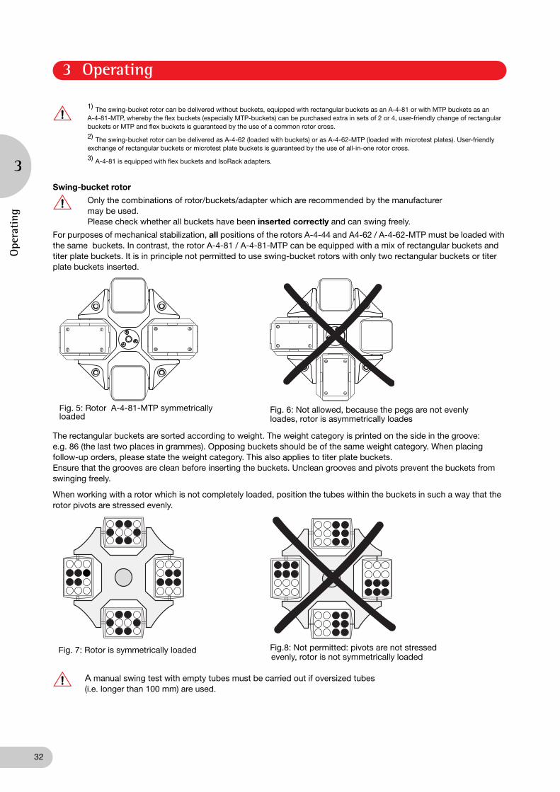
Only the combinations of rotor/buckets/adapter which are recommended by the manufacturer may be used.Please check whether all buckets have been inserted correctly and can swing freely.
For purposes of mechanical stabilization, all positions of the rotors A-4-44 and A4-62 / A-4-62-MTP must be loaded with the same buckets. In contrast, the rotor A-4-81 / A-4-81-MTP can be equipped with a mix of rectangular buckets and titer plate buckets. It is in principle not permitted to use swing-bucket rotors with only two rectangular buckets or titer plate buckets inserted.
The rectangular buckets are sorted according to weight. The weight category is printed on the side in the groove: e.g. 86 (the last two places in grammes). Opposing buckets should be of the same weight category. When placingfollow-up orders, please state the weight category. This also applies to titer plate buckets.Ensure that the grooves are clean before inserting the buckets. Unclean grooves and pivots prevent the buckets from swinging freely.
When working with a rotor which is not completely loaded, position the tubes within the buckets in such a way that the rotor pivots are stressed evenly.
A manual swing test with empty tubes must be carried out if oversized tubes(i.e. longer than 100 mm) are used.
Fig. 5: Rotor A-4-81-MTP symmetrically loaded
Fig. 6: Not allowed, because the pegs are not evenlyloades, rotor is asymmetrically loades
Fig. 7: Rotor is symmetrically loaded Fig.8: Not permitted: pivots are not stressedevenly, rotor is not symmetrically loaded
Ope
rating
3 Operating
3

33
Permitted loads for the swing-bucket rotor
The weight specifications printed on the rotor (e.g. 4 x 0.6 kg for the 4 x 100 ml swing-bucket rotor A-4-44) correspond to the overall weight of the rectangular bucket, inclusive of adapter, test tubes and the contents of each individual position.
In general, commercially-available deepwell plates with a 96-well plate format may only be used in the buckets of the A-4-62-MTP on condition that the maximum load does not exceed 380 g and the maximum height of the plate does not exceed 53 mm. This restriction also applies to stacked titer plates or culture plates.
Commercially available deepwell plates or filter plates / filter plate stacks in the 96-well plate format may be inserted in the buckets of the A-2-DWP only if their load does not exceed 380 g and their height does not exceed 89 mm. These restrictions also apply to stacked titer plates or culture plates.
Commercially available deepwell plates or filter plates//filter plate stacks may be inserted in the buckets of the A-4-81-MTP only if their load does not exceed 380 g and their height does not exceed 60 mm. These restrictions also apply to stacked titer plates or culture plates.
If deepwell plates used with dimensions which do not correspond to the values stated above (e.g. prototypes, combination plates with a heavy lid or specially designed plates), the user must consult Eppendorf to establish the suitability of using these plates in a titer plate or Deepwell plate rotor.
Under no circumstances use MTP-, MTP / Flex- and DWP- buckets with deformed side plates.
Rotor A-4-44(4 x 100 ml)
A-2-DWP(Deepwell-plate rotor)
A-4-62(4 x 250 ml)A-4-62-MTP
A-4-81(4 x 400 ml)A-4-81-MTP
Maximum load per 100 ml rectangular bucket
310 g(adapter + tubes) –––
630 g(adapter + tubes)
780 g(adapter + tubes)
Maximum load per plate carrier
–––
380 g
(with full plates)
380 g
(with full plates)
380 g
(with full plates)
Maximum load per 50 ml Falcon® bucket
144 g(for two conical tubes incl. liquid and form insert)
––– ––– –––
Specifications on the rotor (weight for loaded buckets /rectangular buckets)
4 x 0.6 kg 2 x 1.010 kg 4 x 1.1 kg 4 x 1.4 kg(A-4-81)
4 x 1.22 kg(A-4-81-MTP)
Turn on the main power switch. The nominal values of the last run are displayed.
Load the rotor symmetrically and close the centrifuge lid. The Open key lights blue.
activates the preset speed. The SPEED display flashes.
modify the values. The new nominal value appears in the display.
If the preset speed is in rcf, please check the radius that has been entered. (see Section 3.10).
to select rcf, press this key repeatedly until the rcf symbol ( ) appears to the left of the SPEED display. The rcf value flashes and can be modified using the arrow keys.
3.5 Routine centrifugation with preset time / rcf display
speed
speed
3 Operating
Operating
3

34
Rotor recognition (see also Chapter 3.16) occurs at 200 to 700 1/min and the device then accelerates to the nominal speed.
During the run, the rotational speed of the rotor or the appropriate rcf value, the sample temperature and the remaining spin time in minutes are displayed. The last minute is counted down in seconds. During the run, all parameters can be modified.
After the end of a run, or after a run has been interrupted by pressing the Stop key, the rotor is braked and brought to a standstill. During the braking process, the time display flashes and the elapsed spin time is displayed.
When the lamp in the Open key lights up, the lid can be unlocked by pressing the key.
If the Short key is pressed while the lid is open, one of the following two status signs will appear, depending upon the rotor recognized (see Chapter 3.16 Automatic rotor recognition): "rpm max" or "200 – rpm"
The status displays mean:
"rpm max": The inserted rotor accelerates to its nominal rotational speed.
"200 – rpm": The maximum rotational speed for the short-spin run can be set over the arrow keys.
If the Short key is pressed for longer than three seconds while the centrifuge lid is open, the device will switch over to the other status and display it for two seconds. The status set last will be maintained.
activates the preset time. The TIME display flashes. The time can be modified using the arrow keys.
activates the preset temperature. The nominal temperature in °C can be modified using the arrow keys.
starts the run. flashes and displays the rotation of the rotor.
The continuous operation function is set above 99 min or below 1 min using the arrow keys. In the time display, "oo" indicates continuous operation. During the run, the actual rotational speed/ RCF and temperature values and the elapsed time in minutes are displayed. If the centrifuge runs for more than 99 min, "99." appears in the display. The run is ended with the STOP key.
Press for as long as the run should last. The text "SH" will appear in the display. The elapsed time is displayed in seconds. An already interrupted run can be continued up to two times by repeatedly pressing the key, as long as the centrifuge has not yet come to a stillstand.
Press this key during the run (not during the braking phase).
Change the duration of the run. The time elapsed is taken into account in the new actual value.
time
temp
startstop
3.6 Continuous operation
time
3.7 Short spin centrifugation (Short spin)
short
3.8 Time change during the run
time
Ope
rating
3 Operating
3

35
The nominal temperature value can be set from – 9 °C to + 40 °C. It can be modified during centrifugation.
Once the nominal temperature value has been reached, a deviation greater than ± 3 °C is indicated by a flashing temperature display.
If the temperature deviates by more than 5 °C, a periodic warning signal can be heard and the centrifuge switches itself off.
Starts a temperature run at a rotor and temperature-specific speed for the best possible refrigeration. The new preselected temperature is quickly attained in the rotor by cooling. FT appears in the PROG field. The run is then ended automatically at the arrived at nominal temperature or by pressing the Stop key. A signal can be heard at regular intervals.The centrifuge does not terminate the run until the rotor, carrier or rectangular bucket have reached the pre-selected temperature. The target temperature is initially measured on the chamber and then shown in the display. However, the temperature run is automatically terminated when the rotor, carrier or rectangular bucket have reached the target temperature.
Standby-refrigeration
When the lid is closed, the rotor chamber is refrigerated to the preselected nominal temperature before or after a run, as long as this value is below ambient temperature. The rotor does not turn during this procedure and the temperature changes more slowly.
If the centrifuge is not used for longer than 8 hours, or if the lid is not opened for this time, the refrigeration function switches off. Standby off appears in the display, together with the nominal temperature in the rotor chamber. The desired temperature can be reached rapidly via the Fast Temp function.
The standby cooling of the centrifuge can also be switched on permanently. To do this the Temp and Prog keys must be pressed simultaneously. Standby 8h appears in the display. Following this, the Fast temp must be pressed immediately in order to switch the standby cooling over into permanent operation. Standby endless appears in the display.
The standby cooling is automatically switched off after 8 hours in order to protect the device. The switching of standby cooling to permanent operation is carried out at own risk and can lead to overheating of the compressor.
Please empty and clean the tray for condensation water (on the right at the bottom of the device) on a regular basis.
Remove any condensation water and ice regularly from the rotor chamber using a soft, moist cloth. Defrosting is recommended for ice removal.
The internal conversion of rotational speed to RCF occurs as a standard with the largest radius A smaller radius can be entered for another adapter.
Press this key repeatedly until the radius symbol ( ) appears to the left of the SPEED display.The radius value flashes.
Change the values entered. The new rcf value appears three seconds (or 10 s during the stillstand) after the rotor radius has been entered.
3.9 Refrigeration (for 5804 R / 5810 R only)
temp
fasttemp
3.10 Preset radius
speed
3 Operating
Operating
3

36
If the maximum acceleration / deceleration speed (level 9) is not desired, it is possible to set the speeds in nine different levels.
Approximate braking times for different rotors for the levels 0 to 9 (in seconds) for 230 V centrifuges
The given times are to be considered guidelines. While level 9 means "strongest braking", level 0 means "free deceleration", whereby considerable fluctuations can occur with this uncontrolled deceleration depending upon the condition of the device and the load. The deceleration times for the 230 and 120 V devices are almost identical.
The "at set rpm" function triggers a counting down of the centrifugation time upon achieving the preselected rotational speed ("at set rpm").
Pressing the START / STOP key for longer than 4 seconds while the centrifuge lid is open triggers a switching over to the "at set rpm" function. While the key is pressed, both triangles of the pictogram are illuminated in blue in an alternating sequence. The activated "at set rpm" function is symbolized by the continuously illuminated, upper blue trianglein the pictogram .
In order to leave the "at set rpm" function again, and thus to activate the countdown of the centrifugation time directly after switching on the centrifuge, press the START / STOP key while the centrifuge lid is open. The standard setting is selected again after 4 seconds, symbolized by the illumination of the lower triangle in the pictogram .
Press this key repeatedly until (the symbol for the acceleration levels) appears next to the TIME display
Presetting the acceleration level 9 – 0.
Deceleration is set in the same way .Braking level 0 corresponds to free deceleration.
For levels 0 – 8, the symbols appear in the display.
5804 / 5804 R 5810 / 5810 R Rotor 0 1 2 3 4 5 6 7 8 9
– ● A-4-81 532 189 174 143 131 109 95 85 59 31
– ● A-4-81-MTP / Flex 643 191 174 142 131 110 94 83 58 30
– ● A-4-62 740 190 170 140 130 110 95 85 55 26
– ● A-4-62-MTP 620 190 170 140 130 110 95 85 55 26
● ● A-4-44 470 300 270 220 200 140 100 75 45 23
● ● A-2-DWP 304 174 130 118 100 75 51 44 32 14
● ● T-60-11 800 280 140 95 70 55 45 40 36 36
● ● F-34-6-38 880 370 280 190 170 150 125 95 75 54
● ● F-45-30-11 240 140 70 45 35 30 25 22 19 18
● ● FA-45-30-11 240 140 70 45 35 30 25 22 19 18
● ● F-45-48-PCR 169 119 60 41 31 26 22 19 17 16
3.11 Centrifugation with Soft start / stop
time
3.12 At set rpm
Ope
rating
3 Operating
3

37
Programs can only be preselected when the device is at a standstill.
Storing a fixed program (only possible when the device is at a standstill):
It is possible to save a maximum of 35 fixed programs (1...9, A...Z)..
Enter the program data to be used first by pressing the parameter keys and the arrow keys or use the data from the last run. The "at set rpm" functions and the set deceleration ramp can also be saved in a program if necessary.
If parameters are modified during the run with a fixed program, "0" appears in the PROG field and the user exits the program without it being modified.
To exit the fixed program, call up program "0" or modify the parameters.
In order to avoid accidental deletion of an existing fixed program, the old data set must be deleted while the lid is open prior to renewed assignment of a program number.
Press this key once ➔ the program no. that has been set flashes.0 Data from last run.1...9, A...Z Fixed programs.
Select further program numbers.
Returns to program 0 or leaves the programming mode when the lid is open.
In order to start the selected program immediately, the centrifuge lid must be closed prior to pressing the START / STOP key.
Press this key twice ➔ the first free program no., indicated by "P...", appears in the display and flashes.
The desired free program number (1...9, A...Z) can be selected.
Hold down this key for two seconds until ok appears in the display. The previously set parameters of Temp., Speed, Time, etc. are now saved as a data set.
Press this key once ➔ the program no. display flashes.
Select the program no. which is to be deleted.
Within 10 seconds, keep depressed for 2 seconds until cleared appears in the display.
3.13 Preset program
prog
startstop
3.14 Programming
prog
prog
3.15 Write protection
prog
startstop
3 Operating
Operating
3

38
All nominal values are displayed when the centrifuge is at a standstill. During a run, all nominal values can be displayed for 2.5 seconds by pressing one of the parameter keys (Temp, Speed, Time).
Automatic rotor recognition occurs at the beginning of each run.When a new rotor is recognized, the maximum rotational speed appears in the display for two seconds.If the nominal speed set is greater than the maximum speed for the rotor used, it is aligned to the maximum speed and the run is interrupted. SPEED appears in the display and the run must be restarted.
The rotational speed and the radius for the rcf value will be reset to the maximum permitted value.
If a run with a program has been started, the program number is set to "0".
All centrifuge functions can be operated via the serial interface (RS 232). The appropriate conversion must be carried out by the service department.
Only devices which have been tested in accordance with IEC 950 may be connected via the serial interface.
If the magnetic lid latch cannot be activated because of a power failure, the emergency lid release can be activated manually:
Turn off the main power switch. Wait until the rotor has come to a standstill (The rotor may continue spinning for up to eight minutes). Insert the standard rotor key into the opening in the middle of the front part in the nut underneath and turn counter-clockwise. This disengages the lid, allowing it to be opened.
Be absolutely sure to remove the rotor key afterwards.
The 230 V and 120 V devices have built-in thermal overload switches which function as all-pole fuses. When the overload protection is actuated, these switches over the power switch to OFF, but do not switch it on again automatically.
To turn on the overcurrent protector switch again, please turn off the centrifuge for 10 seconds with the mains power switch. When the centrifuge is subsequently turned on again, the overcurrent protector switch will be automatically reactivated.
If the Time key and the Prog key are pressed simultaneously, the total running time (in hours) of the centrifuge appears in the display. This function can only be selected when the rotor is at a standstill.
Press the Speed and Time keys simultaneously. "Alarm on" and "Alarm off" appear after 2 seconds alternately in the display.
If the Service program has been selected accidentally, press both arrow keys simultaneously.
3.16 Nominal value display
3.17 Automatic rotor recognition
3.18 Display of elapsed spin time
time prog
3.19 Switching on/off the warning signal
timespeed
3.20 Exiting the Service program
3.21 Control via serial interface (optional)
3.22 Opening the centrifuge in the case of a power failure
3.23 Overload cutout switch / Fuses
Ope
rating
3 Operating
3
39
The outside of the centrifuge and the rotor chamber should be cleaned regularly with neutraldetergent. This is for hygiene purposes as well as to prevent contamination caused by residualcontamination.
The user is responsible for cleaning or decontaminating the centrifuge in the event of contamination caused by high-risk substances.
Open the lid of the centrifuge and disconnect the main power plug. Unscrew the rotor with the rotor key provided and clean separately. Only neutral agents may be used for cleaning and disinfection (e.g. diluted Extran® neutral, RBS neutral or 70 % isopropanol/water mixture or an alcohol-based disinfectant). The rotor chamber should only be cleaned with a moist cloth.
After cleaning with detergent, the rubber seals in the rotor chamber should be rinsed well with water and lubricated with glycerine in order to prevent the seals from becoming brittle.
If condensation water forms in the rotor chamber after freezing occurs, dry with a soft absorbent cloth.
The user must consult the manufacturer before cleaning or decontaminating the centrifuge using methods not recommended by the manufacturer in order to ensure that the centrifuge and accessories are not damaged. To ensure that the centrifuge functions correctly and safely in the long-term, please note that aggressive chemicals can damage the rotor, buckets and boiler. Please check the centrifuge regularly for damage caused by corrosion.
The rotor and buckets must be cleaned regularly to prevent contamination caused by residue. Check at least the rotor and housing monthly for residue and corrosion. This applies in particular to the rotor bores. Please clean your rotor using a neutral cleaning liquid. This will protect the rotor and prolong its service life. As a reminder, the message "clean rotor" appears in the display of the centrifuge three times after every 200 runs.
When using the swing-bucket rotor, ensure that the grooves in which the buckets are fitted are free of contamination. The buckets can be lubricated with the lubricant (grease for pivots) supplied, although care must be taken to ensure that the buckets can still swing freely.
On aerosol-tight rotor FA-45-30-11, the rotor lid should be replaced in the event of the lip sealing ring and the sealing ring on the lid screw fitting becoming worn. To protect the rotor, please ensure that the sealing rings are maintained regularly.
When handling the rotor lid, please observe the specifications regarding the chemical resistance of the materials of construction.
The cover of the aerosol-tight rotor must not be fastened tightly during storage!
All rotors are autoclavable (121 °C, 20 min).After the rotor has been autoclaved ten times, the lids of the aerosol-tight buckets or rotors must be exchanged.
The aerosol-tight Rotor FA-45-30-11 and the lid can be autoclaved at 142 °C for 2 hours to destroy prions, but the aerosol-tight lid must be exchanged after each autoclaving.
4.1 Device
4.2 The rotors
4.3 The aerosol-tight rotor
4.4 Rotor sterilization
4 Maintenance and cleaning
Maintenance and cleaning
4

40
When centrifuging glass tubes, please observe that high speeds/rcf’s increase the risk of glass breakage. Please follow the manufacturer’s instructions concerning the maximum speed/rcf of centrifuge tubes. In the event of glass breakage, carefully remove all splinters and all ground glass from the rotor, the buckets, the adapters and the rotor chamber. You may need to replace the rubber mats and adapters to prevent further damage.
Fine splinters of glass may otherwise scratch the surface of the rotors and buckets, reducing their resistance to chemicals. The air turbulences within the rotor chamber produce a very fine black powder of abraded metal. In addition to causing damage to the rotor chamber, rotor, buckets and adapters, the powder also contaminates the samples.
Check the rotor bores regularly for residues and damage.
Clean the refrigeration mesh of the heat exchanger (on the rear side of the device) with a brush at least twice a year. Be sure to first switch off the centrifuge and pull the plug.
Switch off the centrifuge after use, leave the lid open and empty the tray for condensation water, situated below the device on the front right-hand side.
When returning centrifuges, please ensure that the devices have been decontaminated and thereby do not present a health risk to our Service staff.
You will find additional information and a blank of the decontamination confirmation at www.eppendorf.com. Do also consult your laboratory safety officer about a suitable decontamination method.
Please fill out the decontamination confirmation and place it together with the device when it is to be sent back to Eppendorf.
4.5 Glass breakage
4.6 Refrigerated centrifuges
4.7 Return of devices
Mai
nten
ance
and
cle
anin
g
4 Maintenance and cleaning
4
41
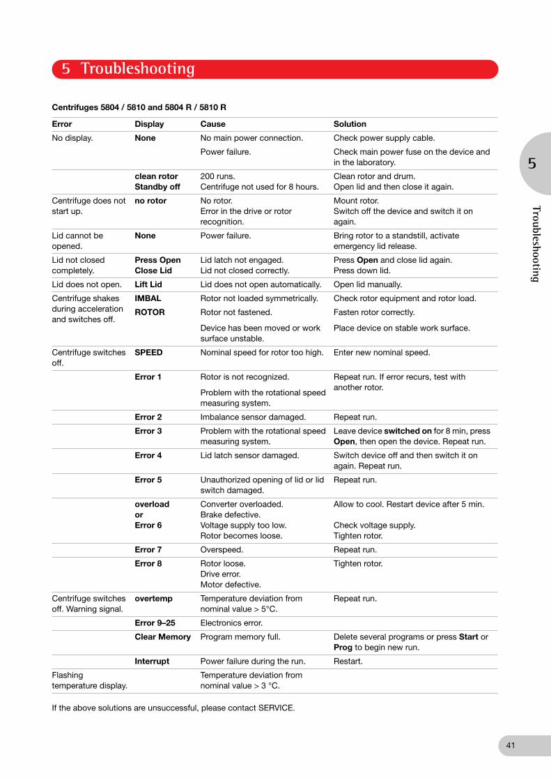
Centrifuges 5804 / 5810 and 5804 R / 5810 R
If the above solutions are unsuccessful, please contact SERVICE.
Error Display Cause Solution
No display. None No main power connection. Check power supply cable.
Power failure. Check main power fuse on the device and in the laboratory.
clean rotorStandby off
200 runs.Centrifuge not used for 8 hours.
Clean rotor and drum.Open lid and then close it again.
Centrifuge does not start up.
no rotor No rotor.Error in the drive or rotor recognition.
Mount rotor.Switch off the device and switch it on again.
Lid cannot be opened.
None Power failure. Bring rotor to a standstill, activate emergency lid release.
Lid not closed completely.
Press OpenClose Lid
Lid latch not engaged.Lid not closed correctly.
Press Open and close lid again.Press down lid.
Lid does not open. Lift Lid Lid does not open automatically. Open lid manually.
Centrifuge shakes during acceleration and switches off.
IMBAL Rotor not loaded symmetrically. Check rotor equipment and rotor load.
ROTOR Rotor not fastened.
Device has been moved or work surface unstable.
Fasten rotor correctly.
Place device on stable work surface.
Centrifuge switches off.
SPEED Nominal speed for rotor too high. Enter new nominal speed.
Error 1 Rotor is not recognized.
Problem with the rotational speed measuring system.
Repeat run. If error recurs, test with another rotor.
Error 2 Imbalance sensor damaged. Repeat run.
Error 3 Problem with the rotational speed measuring system.
Leave device switched on for 8 min, press Open, then open the device. Repeat run.
Error 4 Lid latch sensor damaged. Switch device off and then switch it on again. Repeat run.
Error 5 Unauthorized opening of lid or lid switch damaged.
Repeat run.
overloadorError 6
Converter overloaded.Brake defective.Voltage supply too low.Rotor becomes loose.
Allow to cool. Restart device after 5 min.
Check voltage supply.Tighten rotor.
Error 7 Overspeed. Repeat run.
Error 8 Rotor loose. Drive error.Motor defective.
Tighten rotor.
Centrifuge switches off. Warning signal.
overtemp Temperature deviation from nominal value > 5°C.
Repeat run.
Error 9–25 Electronics error.
Clear Memory Program memory full. Delete several programs or press Start or Prog to begin new run.
Interrupt Power failure during the run. Restart.
Flashing temperature display.
Temperature deviation from nominal value > 3 °C.
5 Troubleshooting
Troubleshooting
5

42
Centrifuges 5804 / 5804 R 5810 / 5810 R
Power supply: 230 V / 50 or 60 Hz 230 V / 50 or 60 Hz
Maximum power requirement: 5804 / 5810 900W 900 W 5804 R / 5810 R 1650 W 1650 W
Fuse protection: 5804 / 5810 Excess current switch 12 A Excess current switch 12 A 5804 R / 5810 R Excess current switch 12 A Excess current switch 12 A
Max. rotational speed: 14 000 rpm 14 000 rpm
Max. centrifugal force: 20 800 rcf 20 800 rcf
Max. kinetic energy: 5804 / 5810 19 000 Nm (11 000 rpm) 19 000 Nm (11 000 rpm) 5804 R / 5810 R 19 000 Nm (11 000 rpm) 23 000 Nm (12 000 rpm)
Max. load: 4 x 100 ml 4 x 400 ml
Max. density of material to be centrifuged: 1.2 g/ml 1.2 g/ml
Permitted ambient temperature during operation: 5804 / 5810 2 °C to 40 °C 2 °C to 40 °C 5804 R / 5810 R 15 °C to 35 °C 15 °C to 35 °C
Permitted maximum relative air humidity: 75 % 75 %
Degree of contamination 2 2
Overvoltage category II II
Standardized interface (optional) RS 232 C RS 232 C
Noise level < 65 dB (A) < 65 dB (A)
Dimensions (W x D x H): 5804 / 5810 466 x 496 x 337 mm 535 x 536 x 345 mm
(D = 550 with operating (D = 608 with operatingsection) section)
5804 R / 5810 R 634 x 496 x 342 mm 700 x 536 x 345 mm (D = 550 with operating (D = 608 with operatingsection) section)
Weight: 5804 / 5810 55 kg 68 kg 5804 R / 5810 R 80 kg 99 kg
Electrical data for 120 V model
Power supply: 120 V / 60 Hz 120 V / 60 Hz
Maximum power requirement: 5804 / 5810 950 W 950 W 5804 R / 5810 R, 20 A version 1650 W 1650 W 5804 / 5810 R, 15 A version 1300 W 1300 W
Fuse projection in the device: 5804 / 5810 Excess current switch 12 A Excess current switch 12 A 5804 R / 5810 R, 20 A version Excess current switch 18 A Excess current switch 18 A 5804 / 5810 R, 15 A version Excess current switch 15 A Excess current switch 15 A
Technical specifications subject to change!
Tech
nica
l dat
a
6 Technical data
6

43
Centrifuge 5804
Bench-top centrifuge, max. load 4 x 100 mlwith rotational speed regulation up to 14,000 rpm230 V / 50– 60 Hz, not including rotor 5804 000.013
Centrifuge 5804 R
Refrigerated bench-top centrifuge, max. load 4 x 100 mlwith rotational speed regulation up to 14,000 rpmTemperature range: –9 to 40 °C230 V / 50 Hz, not including rotor 5805 000.017
Other voltages or 60 Hz frequency upon request.
Captain Eppi
, Rotor key holder, 1 piece 5703 350.102
Captain Eppi
, Rotor key holder, 10 pieces 5703 350.110
Rotor stand, for all rotors for Centrifuges 5804 5804 R / and 5810 / 5810 R 5804 720.008
Swing-bucket rotor and accessories
for Centrifuge 5804 / 5804 R
Swing-bucket rotor A-4-44 (4 x 100 ml),with 4 rectangular buckets of 100 ml 5804 709.004
1 rectangular bucket of 100 ml with weight category (for individual deliveries,please state the existing weight category 5804 701.003
2 aerosol-tight caps for 100 ml rectangular bucket 5804 712.005
4 replacement seals for aerosol-tight caps of the rectangular bucket 100 ml 5804 713.001
Adapters for standard test tubes, blood withdrawal systems and micro test tubesfor 100 ml rectangular bucket (Number and diameter of bores)
2 adapters for 3 – 5 ml test tubes (14 x 11) 5804 750.0042 adapters for 1.5 – 2 ml micro test tubes (12 x 11) 5804 751.0002 adapters for 4 – 7 ml test tubes (12 x 13) 5804 752.0072 adapters for 3 – 15 ml test tubes (7 x 16) 5804 753.0032 adapters for 7 – 17 ml test tubes (6 x 17.5) 5804 754.0002 adapters for 7 – 18 ml test tubes (4 x 20) 5804 756.0022 adapters for 12 – 30 ml test tubes (2 x 26) 5804 757.0092 adapters for 30 – 50 ml test tubes (1 x 31) 5804 759.0012 adapters for 50 – 75 ml test tubes (1 x 35) 5804 760.0002 adapters for 80 – 120 ml test tubes (1 x 46) 5804 761.006
4 replacement rubber mats 5804 782.0032 replacement adapter clamps 100 ml for A-4-44 5804 781.007
Adapters for Falcon
®
test tubes for 100 ml rectangular bucket (Number and diameter of bores)
2 adapters for 15 ml Falcon
®
test tubes (4 x 17.5) 5804 755.0062 adapters for 50 ml Falcon
®
test tubes (1 x 31) 5804 758.005
8 adapters for 50 ml Falcon
®
test tubes, skirted 5804 737.008
4 carriers for 50 ml Falcon
®
test tubes (2 x 31) 5804 706.0058 replacement adapters for 50 ml Falcon
®
tubes as re-order 5804 728.009
Deepwell plate rotor A-2 DWPwith 2 DWP buckets for deepwell plates 5804 740.009
2 DWP buckets for swing-bucket rotor A-2-DWP as replacement 5804 743.008
Deepwell plate bucket with weight category for swing-bucket rotor A-2-DWP(individual delivery only as a replacement delivery with prior agreement) 5804 740.700
7 Ordering information
Ordering inform
ation
7
02B_5804_5810_R_en.fm Seite 43 Mittwoch, 6. September 2006 10:21 10

44
Fixed-angle rotors and accessories for the centrifuges 5804 / 5804 R 5810 / 5810 RFixed-angle rotor 6 x 85 ml, type F-34-6-38with rotor lid 5804 727.002
Replacement lid for rotor F-34-6-38 5804 727.509
2 adapters for micro test tubes (4 x 11.5) 5804 770.0052 adapters for 7 – 15 ml test tubes (2 x 16.5) 5804 771.0012 adapters for 15 – 18 ml test tubes (1 x 18.5) 5804 772.0082 adapters for 20 – 30 ml test tubes (1 x 26.5) 5804 773.0042 adapters for 50 ml test tubes (1 x 29) 5804 774.0002 adapters for 50 ml Falcon® test tubes (1 x 29.5) 5804 775.0072 adapters for 15 ml Falcon® test tubes (1 x 17) 5804 776.003
Fixed-angle rotor 30 x 1.5 ml, type F-45-30-11with rotor lid 5804 715.004
Replacement lid for rotor F-45-30-11 5804 715.403
Fixed-angle rotor 30 x 1.5 ml, type FA-45-30-11aerosol-tight, with rotor lid of aluminium 5804 726.006Replacement lid for rotor FA-45-30-11 5804 736.001
6 adapters for 0.4 ml centrifuge tubes 5425.717.0086 adapters for 0.5 ml micro test tubes and Microtainers® 5425 716.0016 adapters for 0.2 ml PCR-tubes 5425 715.005
PCR-strip rotor F-45-48-PCR for6 x 8-strips, 6 x 5-strips, 48 x 0.2 ml PCR-tubes 5804 735.005
Drum rotor and accessories for the centrifuges 5804 / 5804 R 5810 / 5810 RDrum rotor T-60-11 with rotor lid, for 60 x 1.5 ml / 2 ml tubes / 120 x 0.4 ml tubeswith 6 adapters for 1.5 ml /2 ml tubes 5804 730.003
Adapter for 1.5 ml / 2 ml tubes (set of 6) 5804 731.000Adapter for 0.4 ml tubes (set of 6) 5804 732.006
Accessories for the Centrifuges 5804 / 5804 RGrease for pivots 5810 350.050Standard rotor key 5810 350.018Conversion kit for interface for 5804 Upon requestConversion kit for interface for 5804 R Upon requestTray for condensation water 5811 001.068
Important note:Please use the original accessories recommended by Eppendorf. Using spare parts or disposables which we have not recommended can reduce the precision, accuracy and life of the centrifuges. We do not honor any warranty or accept any responsibility for damage resulting from such action.
F A 45 30 11 A 4 81
Rotor code Fixed-angle Angle of adapter bore
Ø Tube/ Adapter
Swing-bucket rotor
Ø tube/adapter bore
All Eppendorf rotors are designatedaccording to a simple, logical system which describes the technical specifi-cations as a uniform series of numbers and letters e.g.:
Aerosol-tight version
Max. no. tubes/ adapters
Max. no tubes/ adapters
rotor
Ord
erin
g in
form
atio
n
7 Ordering information
7

45
Centrifuge 5810
Bench-top centrifuge, max. load 4 x 400 mlwith rotational speed regulation up to 14,000 rpm230 V / 50–60 Hz, not including rotor 5810 000.017
Centrifuge 5810 R
Refrigerated bench-top centrifuge, max. load 4 x 400 mlwith rotational speed regulation up to 14,000 rpmTemperature range: – 9 to 40 °C230 V / 50–Hz, not including rotor 5811 000.010Other voltages or 60 Hz frequency upon request.
Rotor stand, for all rotors for Centrifuges 5804 5804 R / and 5810 / 5810 R 5804 720.008
Swing-bucket rotor and accessories
for Centrifuges 5810 / 5810 R
Swing-bucket rotor A-4-81 (4 x 400 ml) with 4 rectangular buckets of 400 ml 5810 718.007
Swing-bucket rotor A-4-81 without buckets (for 400 ml buckets or MTP/Flex- buckets) 5810 743.0011 rectangular bucket of 400 ml with weight category(for individual deliveries, please state the existing weight category) 5810 719.003
2 aerosol-tight caps for 400 ml rectangular bucket 5810 724.007
Replacement cap sealings 5810 733.006
Adapters for standard test tubes, Vacutainers and Falcons
®
for400 rectangular bucket:
2 adapters for 2.6 x 7 ml (25 x 13, number and diameter of bores) 5810 720.0012 adapters for 5 ml (Monovette
®
; 18 x 13) 5825 717.0072 adapters for 7 x 17 ml (16 x 17.5) 5810 721.0082 adapters for 5 ml Falcon
®
(12 x 7.5
)
5810 722.0042 adapters for 50 ml Falcon
®
(5 x 31
)
5810 723.0002 adapters for 180 - 250 ml tubes (1 x 62) 5825 720.0082 adapters for 400 ml (1 x 81) 5810 728.0022 adapters for Centriprep
®
‚ Centrifugal Filter Units (5 x 31) 5810 739.004
8 adapters for 50 ml Falcon
®
test tubes, skirted 5804 737.008
4 replacement adapter rubber mats 5810 733.0022 replacement adapter clamps 400 ml for A-4-81 5810 735.009
Replacement rotor key for A-4-81 / A-4-81-MTP 5810 718.309
2 bottles 400 ml 5810 729.009
Swing-bucket rotor A-4-81-MTP, with 4 MTP/Flex- buckets 5810 725.003
4 MTP/Flex- buckets for swing-bucket rotor type A-4-81 MTP or A-4-81 for use of IsoRack adapters, cell culture flasks adapters and MTP, DWP 5810 741.0092 MTP/Flex- buckets 5810 742.0051 MTP/Flex- bucket (individual delivery only as a replacement delivery with prior agreement) 5810 744.008
2 adapters for each cell culture flask for use in the MTP/Flex- buckets 5825 719.0002 adapters for each IsoRack for 0.5 ml micro test tubes 5825 708.0082 adapters for each IsoRack for 1.5 and 2.0 ml micro test tubes 5825 709.004
1 IsoRack Starter Set: 2 IsoRack adapters, 2 IsoRacks with lid,2 x 0 °C cool packs IsoRack; for 0.5 ml and 1.5 ml/2 ml micro test tubes 5825 721.004
Swing-bucket rotor A-4-62 (4 x 250 ml), with 4 rectangular buckets of 250 ml 5810 709.008
1 rectangular bucket of 250 ml with weight category(for individual deliveries, please state the existing weight category) 5810 707.005
2 aerosol-tight caps for 250 ml rectangular bucket 5810 710.006
4 replacement seals for aerosol-tight caps 5810 713.005
Ordering inform
ation
7 Ordering information
7
02B_5804_5810_R_en.fm Seite 45 Mittwoch, 6. September 2006 10:22 10

46
Adapters for standard test tubes, blood withdrawal symptoms and micro test tubes for 250 ml rectangular bucket (Number and diameter of bores)
2 adapters for 1.5 – 5 ml test tubes (25 x 11) 5810 750.0082 adapters for 1.5 – 2 ml micro test tubes (16 x 11) 5810 751.0042 adapters for 4 – 7 ml test tubes (15 x 13) 5810 752.0002 adapters for 3 – 15 ml test tubes (12 x 16) 5810 753.0072 adapters for 7 – 17 ml test tubes (12 x 17.5) 5810 754.0032 adapters for 7 – 18 ml test tubes (8 x 20) 5810 756.0062 adapters for 18 – 30 ml test tubes (4 x 26) 5810 757.0022 adapters for 30 – 50 ml test tubes (4 x 31) 5810 759.0052 adapters for 50 – 75 ml test tubes (2 x 35) 5810 760.0032 adapters for 80 – 120 ml test tubes (1 x 46) 5810 761.0002 adapters for 250 ml test tubes (1 x 62) 5810 770.009
8 adapters for 50 ml Falcon
®
test tubes, skirted 5804 737.008
4 replacement rubber mats5810 782.0074 replacement rubber mats for adapter 5810 770.0095810 783.0032 replacement adapter clamps 250 ml for A-4-62 5810 781.000
Adapters for Falcon
®
test tubes for 250 ml rectangular bucket(Number and diameter of bores)
2 adapters for 15 ml Falcon
®
test tubes (9 x 17.5) 5810 755.0002 adapters for 50 ml Falcon
®
test tubes (3 x 31) 5810 758.0092 adapters for 50 ml Falcon
®
-test tubes (4 x 31) 5810 763.002
Swing bucket rotor 4 x 100 ml, type A-4-44, see 5804 / 5804 R and brochure
Swing-bucket rotor A-4-62-MTP, with 4 plate carriers 5810 711.002
4 plate carriers for swing-bucket rotor, A-4-62-MTP, for 4 plates or 1 deepwell plate 5810 702.003
1 plate carriers for swing-bucket rotor, A-4-62-MTP with weight category(individual delivery only as a replacement delivery with prior agreement) 5810 703.000
Deepwell plate rotor A-2 DWP with 2 DWP buckets for deepwell plates 5804 740.0092 DWP buckets for swing-bucket rotor A-2-DWP as replacement 5804 743.008
Deepwell plate bucket with weight category for swing-bucket rotor A-2-DWP(individual delivery only as a replacement delivery with prior agreement) 5804 740.700
2 adapters for 1 x 96-well PCR plate, not stackable 5825 711.0092 adapters for 1 x 384-well PCR plate, not stackable 5825 713.0012 CombiSlide adapters for up to 12 slides/glass slides per MTP bucket 5825 705.005
Accessories for the Centrifuges 5810 / 5810 R
Grease for pivots 5810 350.050Standard rotor key 5810 350.018Special rotor key for A-4-81 / A-4-81-MTP 5810 718.309Conversion kit for interface for 5810 Upon requestConversion kit for interface for 5810 R Upon requestTray for condensation water 5811 001.068
Important note:
Please use the original accessories recommended by Eppendorf. Using spare parts or disposables which we have not recommended can reduce the precision, accuracy and life of the centrifuges. We do not honor any warranty or accept any responsibility for damage resulting from such action.
7 Ordering information
Ord
erin
g in
form
atio
n
7
02B_5804_5810_R_en.fm Seite 46 Mittwoch, 6. September 2006 10:22 10

19.08.2003
98/37/EG, EN 292-2, EN 292-2/A1 98/79/EG, EN 61326
89/336/EWG, EN 55011/B, EN 61000-6-1, EN 61000-3-2, EN 61000-3-3
73/23/EWG, EN 61010-1, EN 61010-2-20
Laborzentrifugen / Laboratory Centrifuges
Centrifugen 5804 / 5804 R , 5810 / 5810 R
5804 900.995-05
EG-KonformitätserklärungEC Conformity Declaration
Das bezeichnete Produkt entspricht den einschlägigen grundlegenden Anforderungen der aufgeführten EG-Richtlinien und Normen. Bei einer nicht mit uns abgestimmten Änderung des
Produktes oder einer nicht bestimmungsgemäßen Anwendung verliert diese Erklärung ihre Gültigkeit.
The product named below fulfills the relevant fundamental requirements of the EC directives and standards listed. In the case of unauthorized modifications to the product
or an unintended use this declaration becomes invalid.
Produktbezeichnung, Product name:
Produkttyp, Product type:
Einschlägige EG-Richtlinien/Normen, Relevant EC directives/standards:
Vorstand, Board of Management: Projektmanagement, Project Management:
Hamburg, Date:
Eppendorf AG · Barkhausenweg 1 · 22339 Hamburg · Germany
0015 033.509-02

Eppendorf Offices
Eppendorf AGRegional Office in MalaysiaTel. +60 3 8023 2769Fax +60 3 8023 3720E-Mail: [email protected]: www.eppendorf.com.my
Eppendorf South Pacific Pty. Ltd.Tel. +61 2 9889 5000Fax +61 2 9889 5111E-mail: [email protected]: www.eppendorf.com.au
Eppendorf AGc/o Schott AustriaTel. +43 1 29017560Fax +43 1 290175620E-Mail: [email protected]: www.eppendorf.com
Eppendorf do Brasil Ltda.Tel. +55 11 30 95 93 44Fax +55 11 30 95 93 40E-Mail: [email protected]: www.eppendorf.com.br
Eppendorf Canada, Ltd.Tel. +1 905 826 5525Fax +1 905 826 5424E-Mail: [email protected]: www.eppendorf.com
Eppendorf AGTel. +86 21 68760880Fax +86 21 50815371E-Mail: [email protected]: www.eppendorf.cn
ASEAN
AUSTRALIA / NEW ZEALAND
AUSTRIA
BRAZIL
CANADA
CHINA
EPPENDORF FRANCE S.A.R.L.Tel. +33 1 30 15 67 40Fax +33 1 30 15 67 45E-Mail: [email protected]: www.eppendorf.fr
Eppendorf VertriebDeutschland GmbHTel. +49 02232 418-0Fax +49 02232 418-155E-Mail: [email protected]: www.eppendorf.de
Eppendorf India LimitedTel. +91 44 52111314Fax +91 44 52187405E-Mail: [email protected]: www.eppendorf.co.in
Eppendorf s.r.l.Tel. +390 2 55 404 1Fax +390 2 58 013 438E-Mail: [email protected]: www.eppendorf.it
Eppendorf Japan Co. Ltd.Tel. +81 3 5825 2363Fax +81 3 5825 2365E-Mail: [email protected]: www.eppendorf.jp
Eppendorf Nordic ApsTel. +45 70 22 2970Fax +45 45 76 7370E-Mail: [email protected]: www.eppendorf.dk
FRANCE
GERMANY
INDIA
ITALY
JAPAN
NORDIC
Eppendorf Ibérica S.L.Tel. +34 91 651 76 94Fax +34 91 651 81 44E-Mail: [email protected]: www.eppendorf.es
Vaudaux-Eppendorf AGTel. +41 61 482 1414Fax +41 61 482 1419E-Mail: [email protected]: www.eppendorf.com
Eppendorf UK LimitedTel. +44 1223 200 440Fax +44 1223 200 441E-Mail: [email protected]: www.eppendorf.co.uk
Eppendorf North AmericaTel. +1 516 334 7500Fax +1 516 334 7506E-Mail: [email protected]: www.eppendorfna.com
see: www.eppendorf.com/worldwide
SPAIN
SWITZERLAND
UNITED KINGDOM
USA
OTHER COUNTRIES
Titel_Rueck_Klapp.fm Seite 4 Mittwoch, 6. September 2006 11:12 11

Your local distributor: www.eppendorf.com/worldwide
Eppendorf AG · 22331 Hamburg · Germany · Tel. +49 40 538 01-0 · Fax +49 40 538 01-556 · E-Mail: [email protected]
Application Support
Europe, International: Tel. +49 1803 666 789 · E-Mail: [email protected]
Asia, Pacific: Tel. +603 8023 2769 · E-Mail: [email protected]
In touch with life
epp
end
orf i
s a
regi
ster
ed t
rad
emar
k.B
582
0 90
0.01
6-08
/090
6 · P
rinte
d in
Ger
man
y · P
rinte
d o
n ch
lorin
e-fr
ee b
leac
hed
pap
er
Titel_Rueck_Klapp.fm Seite 5 Mittwoch, 6. September 2006 11:12 11