center for technical reliable report computing
TRANSCRIPT

Center for Reliable Computing
TECHNICALREPORT
Built-In Reseeding for Built-In Self Test By Ahmad A. Al-Yamani and Edward J. McCluskey
02-3 Center for Reliable Computing (CSL TR # 02-3) Gates Bldg. 2A, Room #236 Stanford University December 2002 Stanford, California 94305-9020
Abstract: Reseeding is used to improve fault coverage in pseudo-random testing. Most of the work done on reseeding is based on storing the seeds in an external tester. Besides its high cost, testing using automatic test equipments (ATEs) makes it hard to test the circuit while in the field. In this report, we present a technique for built-in reseeding. Our technique requires no storage for the seeds. The seeds are encoded in hardware. The seeds we use are deterministic so 100% fault coverage can be achieved. Our technique causes no performance overhead and does not change the original circuit under test. Also, the technique we present is applicable for single-stuck-at faults as well as transition faults. Built-in reseeding is based on expanding every seed to as many ATPG patterns as possible. This is different from many existing reseeding techniques that expand every seed into a single ATPG pattern. This paper presents the built-in reseeding algorithm together with the hardware synthesis algorithm and implementation for both single-stuck faults as well as transition faults.
Funding: This work was supported in part by King Fahd University of Petroleum and Minerals, by LSI Logic under contract number 16517, and by NSF under contract number CSL-FY00-28.
Imprimatur:

Page ii
LOW-OVERHEAD BUILT-IN BIST RESEEDING
By Ahmad A. Al-Yamani and Edward J. McCluskey
CRC Technical Report No. 02-3
(CSL TR No. 02-3) December 2002
CENTER FOR RELIABLE COMPUTING
Gates Bldg. 2A, Room #236 Computer System Laboratory
Department of Electrical Engineering Stanford University
Stanford, California 94305-9020
ABSTRACT
Reseeding is used to improve fault coverage in pseudo-random testing. Most of the work
done on reseeding is based on storing the seeds in an external tester. Besides its high cost, testing
using automatic test equipments (ATEs) makes it hard to test the circuit while in the field. In this
report, we present a technique for built-in reseeding. Our technique requires no storage for the
seeds. The seeds are encoded in hardware. The seeds we use are deterministic so 100% fault
coverage can be achieved. Our technique causes no performance overhead and does not change
the original circuit under test. Also, the technique we present is applicable for single-stuck-at
faults as well as transition faults. Built-in reseeding is based on expanding every seed to as many
ATPG patterns as possible. This is different from many existing reseeding techniques that
expand every seed into a single ATPG pattern. This paper presents the built-in reseeding
algorithm together with the hardware synthesis algorithm and implementation for both single-
stuck faults as well as transition faults.

Page iii
TABLE OF CONTENTS
ABSTRACT.................................................................................................................................... ii
TABLE OF CONTENTS............................................................................................................... iii
LIST OF TABLES......................................................................................................................... iv
LIST OF FIGURES ....................................................................................................................... iv
1. INTRODUCTION .................................................................................................................. 1
2. PREVIOUS WORK................................................................................................................ 2
3. RESEEDING CIRCUITRY IMPLEMENTATION............................................................... 5
4. RESEEDING ALGORITHM ................................................................................................. 9
5. SIMULATION RESULTS ................................................................................................... 11
5.1 Comparison with previous work......................................................................................... 12
5.2 Area overhead and test length for SSFs.............................................................................. 15
5.3 Area overhead and test length for transition faults ............................................................. 16
6. SUMMARY AND CONCLUSIONS ................................................................................... 16
REFERENCES ............................................................................................................................. 17

Page iv
LIST OF TABLES
Table 1: Table of Combinations for the Reseeding Circuit Example ........................................................... 7
Table 2: ISCAS 89 CUTs Used in The Experiments. ................................................................................. 12
Table 3: Comparison of Built-In Reseeding and Previous Work Encoding One Seed per Pattern. ........... 13
Table 4: Area Overhead and Test Length For Built-In Reseeding (SSFs).................................................. 15
Table 5: Area Overhead and Test Length For Built-In Reseeding (Transition Faults)............................... 16
LIST OF FIGURES
Figure 1: Reseeding circuit connection to the LFSR ………………………………………………………6
Figure 2: Example reseeding circuit (a) Select lines computation (b) Hardware implementation ……...…7
Figure 3: Reseeding circuit in a system view of BIST environment ……………………………………....9
Figure 4: Test length vs. CIT (s13207) ………………………………………………………………...…14
Figure 5: Number of seeds vs. CIT (s13207) ……………………………………………………………..14
Figure 6: Test length vs. CIT (average all CUTs) ……………………………………………………...…15
Figure 7: Number of seeds vs. CIT (average all CUTs) …...……………………………………………..15

Page 1
1. INTRODUCTION
An advantage of built-in self-test (BIST) is its low cost compared to external testing using
automatic test equipment (ATE). In BIST, on-chip circuitry is included to provide test vectors
and to analyze output responses. One possible approach for BIST is pseudo-random testing using
a linear feedback shift register (LFSR) [McCluskey 85]. Among the advantages of BIST is its
applicability while the circuit is in the system.
Many digital circuits contain random-pattern-resistant (r.p.r.) faults that limit the coverage of
pseudo-random testing [Eichelberger 83].The r.p.r. faults are faults with low detectability (Few
patterns detect them). Several techniques have been suggested for enhancing the fault coverage
achieved with BIST. These techniques can be classified as: (1) Modifying the circuit under test
(CUT) by test point insertion or by redesigning the CUT [Eichelberger 83, Cheng 95, Touba
96a], (2) Weighted pseudo-random patterns, where the random patterns are biased using extra
logic to increase the probability of detecting r.p.r. faults [Brglez 89, Muradali 90, Wunderlich
90] and (3) Mixed-mode testing where the circuit is tested in two phases. In the first phase,
pseudo-random patterns are applied. In the second phase, deterministic patterns are applied to
target the undetected faults [Koenemann 91, Hellebrand 92, Venkataraman 93, Touba 96b]. The
technique we present is a mixed mode technique based on inserting deterministic patterns
between the pseudo-random patterns.
Modifying the CUT is often not desirable because of performance issues or intellectual
property reasons. Weighted pseudo-random sequences require multiple weight sets that are
typically stored on chip. Mixed mode testing is done in several ways; one way is to apply the
deterministic patterns from an external tester. Although this technique reduces the tester time and
storage required, it still doesn’t eliminate the need for external testing. Another technique is to
store the deterministic patterns on an on-chip ROM. This ROM requires high area overhead on
the chip, needs to be tested, and there needs to be additional circuitry to apply the patterns in the
ROM to the circuit under test. Instead of storing patterns, seeds can be stored on the tester or on
the on-chip ROM. These seeds are loaded into the LFSR and then expanded into the scan chain
of the circuit. This technique reduces the storage needed at the tester or the ROM but it does not
eliminate it. It also does not eliminate the need for the circuitry that applies the seeds from the
ROM to the LFSR.
Another technique for mixed-mode testing is mapping logic [Touba 95]. The strategy is to
identify patterns in the original set that don’t detect any new faults and map them by hardware

Page 2
into deterministic patterns for random-pattern-resistant faults. This mapping is designed to use as
few gates as possible.
In this paper, we present a technique that combines mapping logic and reseeding (loading the
PRPG with a new seed). Our technique uses a simple circuit to identify the cycles at which the
LFSR is to be reseeded and it uses the same circuit to choose the new seed. A distinct feature of
our technique is that it utilizes the LFSR flip-flops for storing the seeds. All that is required is the
circuit that detects the end of sequence (EOS) pattern, which is the last pattern in a sequence of
pseudo-random patterns. This same circuit is used to pick the new seed.
Our technique can be tuned for the desired fault coverage and completely eliminates the need
for external testing or for a ROM to store the seeds. With a small modification, our technique can
be applied for transition faults rather than single stuck faults. Even if it’s more desirable to apply
the deterministic patterns externally than to add the mapping logic, our technique is still
applicable and in this case it outperforms the other reseeding schemes in the amount of storage
required and allows trading off tester storage and test length.
Our contributions in this paper are summarized as follows: (1) A reseeding technique that
eliminates completely the need for external pattern storage and application or an on-chip ROM.
It’s based on encoding the seeds in hardware and using special hardware for the LFSR. The
technique is applied for both single-stuck-at as well as transition faults. (2) The hardware
implementation for the given technique. (3) A reseeding algorithm based on the given hardware
implementation. The algorithm allows the user to trade off test length for hardware overhead.
The output of the reseeding algorithm is the reseeding circuit in a format ready for optimization
and synthesis.
In Sec. 2 of this report, we review the related literature. In Sec. 3, we explain the circuitry
required for implementing the presented scheme. Section 4 discusses the reseeding algorithm.
Section 5 is about the simulation results. Section 6 is the conclusion.
2. PREVIOUS WORK
In serial BIST (aka test per scan), deterministic patterns are encoded into smaller vectors (aka
seeds) that are loaded into the LFSR and then expanded into the desired patterns in the scan
chains. The patterns are encoded into seeds by solving a linear system of equations, which is an
algebraic representation of the linear expansion of the LFSR into the scan chain flip-flops. There

Page 3
are some linear dependencies between some flip-flops of the scan chain. Due to these
dependencies, solving the linear system of equations may not always be possible.
2.1 Seed Calculation
Konemann presented a technique for coding test patterns into LFSRs of size Smax+20, where
Smax is the maximum number of specified bits in the ATPG patterns. By adding 20 bits to Smax as
the size of the LFSR, the probability of linear dependence drops to 1 in a million [Koenemann
91].
The fact that many of the bits in the ATPG-patterns are don’t cares makes Koenemann’s
technique very useful in reducing the storage needed per pattern to Smax+20. Smax depends on the
circuit under test and on the undetected faults that are targeted by the deterministic patterns.
[Zacharia 95] and [Rajski 98] presented a reseeding-based technique that improves the
encoding efficiency by using variable-length seeds together with an MP-LFSR. The authors
presented a technique that reuses part of the scan chain flip-flops in expanding the seeds.
2.2 Seed Storage
In [Huang 97], programmable LFSRs (PLFSRs) are used to enable multiple polynomials for
the PRPG. The authors assume that the seeds are available from an external tester or a ROM. In
[Kagaris 99], a synthesis technique for counter-based test set embedding was presented. They
present a multi-seed counter and they assume that the seeds are stored on the tester or on an on-
chip ROM. [Chakrabarty 00] presented an approach for BIST pattern generation using twisted-
ring counters. In order to achieve good fault coverage they rely on reseeding the counter. The
seeds are stored in a ROM. Hellebrand presented a reseeding technique based on folding
counters. When combined with an input reduction technique, the presented scheme reduced the
seed storage required [Hellebrand 00]. In [Krishna 01], a new form of reseeding was described
for high encoding efficiency. The authors presented partial dynamic reseeding. By making use of
the degrees of freedom in solving the linear system of equations the paper achieves higher
encoding efficiency than static reseeding.
The above schemes assume that seeds are either applied from an external tester or stored in
an on-chip ROM. This paper presents a technique for avoiding this requirement.
Although applying the seeds externally means much less tester storage and bandwidth than if
the patterns were to be stored, it still means that the chip has to be put on the tester. Also,
although the ROM eliminates the need for the tester, there must be some circuitry to choose
when to load seeds from the ROM and other circuitry to actually load them onto the LFSR.

Page 4
The technique presented in this paper embeds the seeds on the chip without requiring a
ROM. Other than the circuit needed to detect when to reseed, minimal hardware is needed to
load the desired seeds. The technique presented in this paper is orthogonal to all of the above
techniques; i.e., it can be combined with Hellebrand’s technique for reducing the LFSR size. It
can also be combined with partial dynamic reseeding for a high encoding efficiency. It can also
be combined with Rajski’s technique that utilizes part of the scan chain or Chakrabarty’s
technique for reusing the scan chain flip-flops as an LFSR.
2.3 Hardware-based reseeding
[Savir 90] presented a reseeding scheme that requires having shadow flip-flops for the LFSR
flips-flops. The shadow flip-flops contain the next seed. These shadow flip-flops are loaded with
the XOR of the old shadow contents and the original LFSR flip-flops contents. This way, the
new seed is expected to be far in the sequence from the current contents of the LFSR. Kim
presented a method for generating non-successive pseudo-random test patterns by cascading the
LFSR with the scan chain and including a feedback from the scan-out signal into the LFSR [Kim
96]. In [Crouch 95], a self re-seeding LFSR was presented. Again the LFSR is loaded with a new
seed every time a pattern is repeated in part of the LFSR.
The above schemes have the advantage of diversity of the sequences from which the patterns
are drawn. They also have the advantage of not requiring seed storage. However, The seeds are
pseudorandom so they don’t target specific faults. Our technique is based on deterministic seeds
so 100% fault coverage can be achieved. We pay the price in hardware overhead compared to the
above schemes.
2.4 Mapping logic
Touba and McCluskey came up with an innovative approach for applying deterministic
patterns through mapping logic [Touba 95]. In their technique, random patterns that don’t detect
r.p.r. faults are mapped to ATPG generated cubes through combinational logic.
Our technique is a generalization of mapping logic based on running the LFSR in
autonomous mode after loading every seed to detect more faults without having to perform more
mappings. Because of this, some patterns may not be required. In our technique we only need the
logic that detects the patterns that need to be mapped. Enforcing the new values in the LFSR is
done utilizing the current contents of the flip-flops of the LFSR.
Page 5
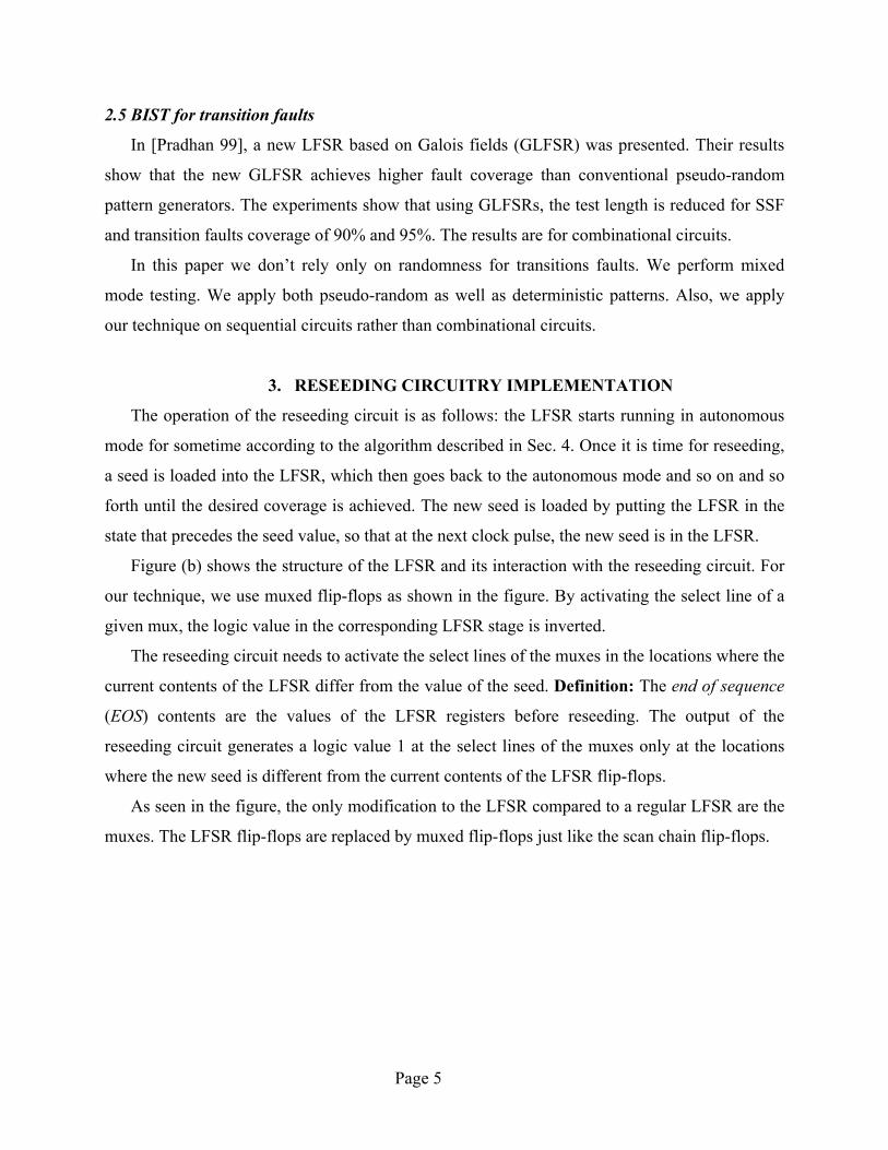
2.5 BIST for transition faults
In [Pradhan 99], a new LFSR based on Galois fields (GLFSR) was presented. Their results
show that the new GLFSR achieves higher fault coverage than conventional pseudo-random
pattern generators. The experiments show that using GLFSRs, the test length is reduced for SSF
and transition faults coverage of 90% and 95%. The results are for combinational circuits.
In this paper we don’t rely only on randomness for transitions faults. We perform mixed
mode testing. We apply both pseudo-random as well as deterministic patterns. Also, we apply
our technique on sequential circuits rather than combinational circuits.
3. RESEEDING CIRCUITRY IMPLEMENTATION
The operation of the reseeding circuit is as follows: the LFSR starts running in autonomous
mode for sometime according to the algorithm described in Sec. 4. Once it is time for reseeding,
a seed is loaded into the LFSR, which then goes back to the autonomous mode and so on and so
forth until the desired coverage is achieved. The new seed is loaded by putting the LFSR in the
state that precedes the seed value, so that at the next clock pulse, the new seed is in the LFSR.
Figure (b) shows the structure of the LFSR and its interaction with the reseeding circuit. For
our technique, we use muxed flip-flops as shown in the figure. By activating the select line of a
given mux, the logic value in the corresponding LFSR stage is inverted.
The reseeding circuit needs to activate the select lines of the muxes in the locations where the
current contents of the LFSR differ from the value of the seed. Definition: The end of sequence
(EOS) contents are the values of the LFSR registers before reseeding. The output of the
reseeding circuit generates a logic value 1 at the select lines of the muxes only at the locations
where the new seed is different from the current contents of the LFSR flip-flops.
As seen in the figure, the only modification to the LFSR compared to a regular LFSR are the
muxes. The LFSR flip-flops are replaced by muxed flip-flops just like the scan chain flip-flops.

Page 6
Q
QSET
CLR
D
Q
QSET
CLR
D
Q
QSET
CLR
D
Q
QSET
CLR
D
Q
QSET
CLR
D
Q
QSET
CLR
D
Q
QSET
CLR
D
Q
QSET
CLR
D
Reseeding Logic
(a)
(b)
CLK
MU
X
MU
X
MU
X
MU
X
Figure 1: Reseeding circuit connection to the LFSR:
(a) A standard 4-stage LFSR (b) 4-stage LFSR with reseeding circuit.
Let’s turn our attention to the reseeding circuit itself by looking at the following example.
Figure 2 is an example using a 4-stage self-reseeding LFSR (LFSR with reseeding logic) with a
primitive polynomial. The table in part (a) shows the full sequence of the regular LFSR. Assume
that we want to reseed after the 6th cycle (c6). The reseeding circuit needs to be an AND gate that
takes as inputs the contents of the LFSR at c6. So in the example the input to the reseeding AND
is 4321 QQQQ . All the cycles that are not part of the desired sequence can be used to minimize the
reseeding circuit. In other words, we can combine the patterns that will activate the reseeding
circuit together with all the patterns that won’t occur in our desired sequence to generate the
maximum possible number of don’t cares.
As an example, let the seed be 0100 (c12); we can easily calculate c11 given the polynomial
of the LFSR (c11 = 1001). The reason we calculate c11 and not c12 is because we want the seed
to be loaded into the LFSR in the next clock cycle. To find the location where c11 is different
from c6 we XOR them, XORing c6 with c11 yields 1100 which means that the output of the
reseeding AND should generate a logic value 1 at the select lines of the MUXes of Q1 and Q2
only.

Page 7
Reseeding Circuit
End of Sequence (EOS) = c6 = 0101Seed = 0100 = c12Select Lines Activated = (c6) XOR (c11) = 0101 XOR 1001 = 1100
=> Select lines of Q1 and Q2 activated
Cycle Q1 Q2 Q3 Q4 Cycle Q1 Q2 Q3 Q40 1 0 0 0 8 1 1 0 11 1 1 0 0 9 0 1 1 02 1 1 1 0 10 0 0 1 13 1 1 1 1 11 1 0 0 14 0 1 1 1 12 0 1 0 05 1 0 1 1 13 0 0 1 06 0 1 0 1 14 0 0 0 17 1 0 1 0 15 1 0 0 0
Q
QSET
CLR
D
Q
QSET
CLR
D
Q
QSET
CLR
D
Q
QSET
CLR
D
(b)
MU
X
MU
X
MU
X
MU
X
(a)
Figure 2: Example reseeding circuit (a) Select lines computation (b) Hardware implementation.
The truth table for the reseeding circuit is shown in Table 1, where Qi comes from the output
of the ith stage and Sj goes into the select lines of the mux of jth stage. The table shows that when
the LFSR has the contents 0101 (c6), S1 and S2 will be activated to load 1001 (c11) in the LFSR.
The patterns between c6 and c11 will not occur so they are don’t cares. All the other patterns
don’t activate any muxes.
Table 1: Table of Combinations for the Reseeding Circuit Example Q1Q2Q3Q4 S1S2S3S4 Q1Q2Q3Q4 S1S2S3S4 Q1Q2Q3Q4 S1S2S3S4 Q1Q2Q3Q4 S1S2S3S4 1 0 0 0 1 1 0 0 1 1 1 0 1 1 1 1
0 0 0 0 0 0 0 0 0 0 0 0 0 0 0 0
0 1 1 1 1 0 1 1 0 1 0 1 1 0 1 0
0 0 0 0 0 0 0 0 1 1 0 0 d d d d
1 1 0 1 0 1 1 0 0 0 1 1 1 0 0 1
d d d d d d d d d d d d 0 0 0 0
0 1 0 0 0 0 1 0 0 0 0 1 0 0 0 0
0 0 0 0 0 0 0 0 0 0 0 0 d d d d
The resulting circuit for the example in Figure 2 is a 3-input AND as shown in the figure.
As more seeds are required, every select line of the MUXes will be a function of the end-of-
sequence patterns that will activate it to complement the contents of its corresponding flip-flop.
We can then optimize the circuit for that select line by combining all the patterns that will
activate it together with all the patterns that won’t occur in the desired sequence. This is like

Page 8
minimizing a function given all of its on-set patterns as well as all of its impossible patterns
(don’t care-set). Furthermore, multiple-output optimization can be done for the select lines.
There are two ways to apply transition fault test sets to circuits with scan chains. One way is
to use pairs of clock pulses (launch on capture). Once the 1st pattern is loaded into the scan chain,
a clock pulse is applied so the response of the combinational logic to the 1st pattern is latched
into the flip-flops. Another clock pulse is then applied such that the response of the
combinational logic to the 1st pattern is used as the 2nd pattern in the transition fault pair. Logic
and fault simulation are used to figure out the response of the 1st pattern and accordingly find the
detected faults. The other way is to load the scan chain with the two successive patterns (launch
on shift). Once the first pattern is applied, the contents of the scan chain are shifted, the 2nd
pattern is applied and the results are captured in the scan chain to be shifted out.
We use the first technique (launch on capture) for transition faults. The reseeding circuit only
needs to load the LFSR with the 1st pattern because the 2nd pattern is the response of the logic to
the 1st pattern. The reseeding circuit is synthesized such that it changes the contents of the LFSR
from the current values to the 1st pattern in the transition fault pattern pair. This means that our
technique requires no extra hardware to apply it to transition faults. Although pairs of 2 vectors
are required for transition faults, only the first pattern needs to be encoded in hardware because
the 2nd pattern is the circuit’s response to the 1st pattern.
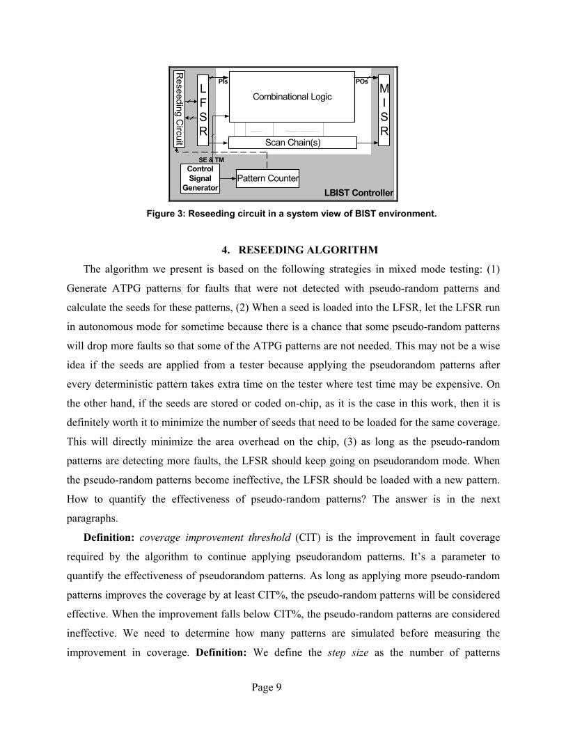
Figure 3 shows where the reseeding circuit fits in a system level view of a circuit with an
LBIST controller, which includes the additional control circuitry added for logic BIST. The
pattern counter is part of the LBIST controller and it is used to count the patterns applied to the
circuit under test (CUT).
In a BIST environment, where the LFSR is known in advance and the initial seed and test
length are also known, the reseeding circuit may take its inputs from the pattern counter instead
of the LFSR contents. The dashed line in Figure 3 corresponds to the reseeding circuit taking its
inputs from the pattern counter. If a set of test length TL is applied to the circuit the pattern
counter will be of size log2(TL). If the size of the pattern counter is much smaller than the
LFSR, this can lead to large reduction in the complexity of the reseeding circuit because the
number of inputs of the reseeding circuit is reduced. Again having both polarities available at the
input gives room for further minimization of the reseeding circuit.
Page 9
LBIST Controller
Combinational LogicMISR
Pattern CounterControlSignal
Generator
SE & TM
PIs POs
Reseeding C
ircuit
LFSR
Scan Chain(s)
Figure 3: Reseeding circuit in a system view of BIST environment.
4. RESEEDING ALGORITHM
The algorithm we present is based on the following strategies in mixed mode testing: (1)
Generate ATPG patterns for faults that were not detected with pseudo-random patterns and
calculate the seeds for these patterns, (2) When a seed is loaded into the LFSR, let the LFSR run
in autonomous mode for sometime because there is a chance that some pseudo-random patterns
will drop more faults so that some of the ATPG patterns are not needed. This may not be a wise
idea if the seeds are applied from a tester because applying the pseudorandom patterns after
every deterministic pattern takes extra time on the tester where test time may be expensive. On
the other hand, if the seeds are stored or coded on-chip, as it is the case in this work, then it is
definitely worth it to minimize the number of seeds that need to be loaded for the same coverage.
This will directly minimize the area overhead on the chip, (3) as long as the pseudo-random
patterns are detecting more faults, the LFSR should keep going on pseudorandom mode. When
the pseudo-random patterns become ineffective, the LFSR should be loaded with a new pattern.
How to quantify the effectiveness of pseudo-random patterns? The answer is in the next
paragraphs.
Definition: coverage improvement threshold (CIT) is the improvement in fault coverage
required by the algorithm to continue applying pseudorandom patterns. It’s a parameter to
quantify the effectiveness of pseudorandom patterns. As long as applying more pseudo-random
patterns improves the coverage by at least CIT%, the pseudo-random patterns will be considered
effective. When the improvement falls below CIT%, the pseudo-random patterns are considered
ineffective. We need to determine how many patterns are simulated before measuring the
improvement in coverage. Definition: We define the step size as the number of patterns

Page 10
simulated before measuring the improvement in coverage. In our simulations, we used different
values for the step size. Algorithm 1 shows the built-in reseeding algorithm.
The only user-specified parameters for this algorithm are the coverage improvement
threshold (CIT) and the step size. At one extreme, choosing a very small CIT, means that the
user prefers to stick to pseudo-random patterns as long as they have any improvement in the
coverage. This in turn means the user wants low hardware overhead for the reseeding circuit. In
return for that, the user is willing to have a long test length. At the other extreme, if the user
specifies a very high CIT, it means that he has enough area on the chip for the reseeding circuit.
However, test length is considered very scarce. In other words, the number of seeds to be loaded
is inversely proportional to the test length and directly proportional to the area of the self-
reseeding circuit as shown in Sec. 5. It’s up to the user to choose which of the two resources is
scarcer in his design. The results in the next section show the impact of CIT on the test length
and on the area of the reseeding circuit.
Reseeding based on CIT is one way to choose when to reseed the LFSR. Many other
strategies can be used for selecting the reseeding cycles. One way is to choose a fixed length for
running the LFSR in autonomous mode after the seed is loaded.
In a sense, our built-in reseeding algorithm is a generalization of mapping logic. If we choose
not to continue running the LFSR in pseudorandom mode after reseeding and we choose to alter
the LFSR output of the LFSR contents, then our technique becomes similar to mapping logic.
We chose to expand the seeds into many patterns since this should reduce the number of seeds to
be loaded and accordingly reduce the area of the reseeding circuit. We also chose to alter the
contents of the LFSR to enable a different sequence of pseudorandom patterns to drop more
faults.
For some circuits, all we need to catch the undetected faults is to take the LFSR to another
location in the pattern space. In that case, one or two seeds are enough. For other circuits, the
undetected faults require many seeds to be loaded. In that case, our technique will have area
overhead close to that of mapping logic. Yet, mapping logic will have a shorter test length. A
major advantage for the technique we present is that it allows the user to discover what type of
circuit he has and accordingly the right parameters can be chosen for an optimal test set.
In case of transition faults, the only change to the algorithm is that fault simulation and
ATPG should be done for transition faults instead of SSFs. ATPG generated transitions fault
patterns have only the 1st pattern specified. The 2nd pattern is the response of the circuit to the 1st

Page 11
pattern. So, only the first patterns of the transition fault patterns’ pairs should be encoded in the
hardware of the reseeding circuit.
TL: Test Length. PF: Patterns File. FC (PF, TL): Fault Coverage of TL patterns from PF. RFC: Required Fault Coverage. CIT: Coverage Improvement Threshold. S: Step Size = Number of patterns simulated in parallel. EOS: End of sequence = the seed of the last pattern in PF. PLA: Input output file used for synthesis of the reseeding circuit. Built-In Reseeding (RFC, CIT, LFSR, S)
1. Run LFSR in autonomous mode for a long enough length. 2. Save the patterns → PF. 3. Fault simulate the patterns in PF on the CUT in groups of S at a time. 4. Let MTL = minimum TL such that: (FC (PF, MTL+S) – FC (PF, MTL)) < CIT 5. Truncate PF at MTL. 6. If FC (PF, MTL) ≥ RFC, Return (PF). 7. Else
a. Run ATPG such that coverage of (MTL + ATPG) ≥ RFC b. Calculate the seeds for the ATPG patterns. c. Save the seeds → SEEDS d. For i=1 to |SEEDS|
i. Pick PAT from SEEDS such that DF=EOS(PF)⊕PAT is minimized ii. If PAT does not improve coverage, pick another one.
iii. Add EOS(PF)to PLA with output DF. iv. Run LFSR in autonomous mode for a long enough length. v. Append patterns → PF. vi. Fault simulate PF patterns on the CUT, S at a time.
vii. Set MTL s.t. it includes PAT && improvement < CIT. viii. Truncate PF at MTL.
ix. If FC (PF, MTL) ≥ RFC, Return (PF, PLA). e. Return (PF, PLA).
Algorithm 1: Built-in reseeding algorithm.
5. SIMULATION RESULTS
In this section we present the results of some simulation experiments we performed using our
built-in reseeding technique. We performed our experiments on some ISCAS 89 benchmarks.
The characteristics of the benchmarks we used are shown in Table 2. The table shows the
number of primary inputs, primary outputs and flip-flops in the circuits. It also shows the size of
the LFSR used. The last column shows the cell-area of the circuits in LSI library cells area units.
The library used for technology mapping is LSI Logic G.Flex library, which is a 0.13 µ
technology library.

Page 12
Table 2: ISCAS 89 CUTs Used in The Experiments.
Circuit Name
PrimaryInputs
Primary Outputs
Scan Chain Size
LFSR Size
Area
s1423 17 5 74 50 4,531 s1488 8 19 6 6 3,555 s1494 8 19 6 6 3,563 s5378 35 49 179 61 14,376 s9234 36 39 211 80 25,840 s13207 62 152 638 45 44,255 s15850 77 150 534 150 48,494 s35932 35 320 1728 60 106,198 s38417 28 106 1636 200 120,180 s38584 38 304 1426 200 115,855
5.1 Comparison with previous work
In order to evaluate the effectiveness of our built-in reseeding technique we performed some
simulation experiments to compare it with previous work. Most of the previous work assumes
one seed per pattern. From here on, “previous work” refers to all work that assumes one seed per
pattern.
We compare the number of seeds that need to be encoded if our built-in reseeding technique
is used and the number of seeds that need to be stored or mapped if previous techniques are used.
The number of seeds determines the area of the reseeding or mapping circuit. Since further area
minimization heuristics can be applied to all techniques, it’s fair to compare them in terms of the
number of seeds that need to be mapped or stored for the same coverage. This comparison can be
done for all possible combinations of coverage improvement threshold (CIT) and step size, see
Sec. 4. Since built-in reseeding may require longer test length than previous techniques, it’s fair
to show the test length in the comparison. Why should we tolerate this increase in test length? (1)
The area is a scarce resource in BIST. (2) The effect of increasing the test length is not as severe
with BIST as it is with external testing because BIST is much faster than external testing. (3)
Increasing the test length increases the number of pseudo-random patterns that are likely to be
effective in catching unmodeled defects. (4) The increase in test length we have is much smaller
than that if only pseudorandom patterns were used. In fact the user has the option to minimize
the test length for area overhead.
Table 3 shows a comparison of previous techniques and our reseeding technique. The table is
for 100% single-stuck-at fault coverage, 1% CIT (coverage improvement threshold) and 1024
patterns as a step size. In its best case, built-in reseeding reduces the number of seeds required

Page 13
for 100% coverage by an order of magnitude and increases the test length by only a factor of 1.7
compared to using one seed per pattern. Overall, the minimum reduction in the number of
patterns is 7%.
Table 3: Comparison of Built-In Reseeding and Previous Work Encoding One Seed per Pattern.
Number of seeds to be encoded Test Length Circuit One seed
per pattern Built-in
reseeding%Reduction Top-off
seeds Built-in
reseeding Degradation
factor s1423 7 4 42.9 2,000 8,160 4.1s1488 4 1 75.0 3,072 4,096 1.3s1494 4 1 75.0 3,072 4,096 1.3s5378 60 20 66.7 3,072 27,648 9.0s9234 93 62 33.3 5,120 76,800 15.0
s13207 121 26 78.5 5,120 60,416 11.8s15850 41 38 7.3 4,096 45,056 11.0s35932 18 1 94.4 3,072 5,120 1.7s38417 78 62 20.5 5,120 89,088 17.4s38584 107 36 66.4 4,096 76,800 18.8
The table shows that there are many cases where reseeding offers a considerable
improvement in the number of patterns required to test the circuit and at the same time doesn’t
cause a large increase in the test length. Also, even in its worst case, built-in reseeding gives
some improvement over previous techniques in terms of the number of seeds to be encoded.
The following charts show how the coverage improvement threshold (CIT) affects previous
work and our built-in reseeding technique for SSF. Fig. 4 shows the test length of previous work
(top-off seeds) and built-in reseeding as a function of CIT for one of the circuits. Recall that
using a high CIT means not accepting random patterns unless they cause significant
improvement on the fault coverage. The required coverage is 100%. For both techniques, the
higher the CIT, the lower the test length. This is because if CIT is higher, then we are using
fewer random patterns and using more deterministic patterns for both techniques. The fewer
random patterns we use, the shorter test length we get.
Let’s now look at the number of patterns or seeds we need for 100% coverage as a function
of the CIT. Fig. 5 shows the number of patterns previous techniques (top-off seeds) require for
100% coverage and the number of seeds built-in reseeding needs for the same coverage as a
function of CIT. For previous work, the higher the CIT, the more deterministic patterns are
required which means larger area overhead for the mapping logic or larger storage for the seeds.
For built-in reseeding, the curve is not monotonically increasing. This simply means that using a

Page 14
larger CIT to get a shorter test length doesn’t necessarily mean a larger area overhead for the
reseeding circuit. In fact, for the given example, using a very high CIT results in many fewer
seeds compared to using a small CIT. This is a significant advantage of built-in reseeding
because it means that we can get double wins both in test length and area overhead, why?
Because built-in reseeding is very sequence dependent, unlike mapping logic. The algorithm we
presented in this paper picks the seed that is closest to the end of the sequence pattern in the
LFSR. This means that by allowing different sequence lengths, the algorithm will end up picking
different seeds that may result in more useful pseudo-random sequences.
Most of the circuits exhibited similar behavior to that shown in Fig. 4 and Fig. 5. Due to
space limitations, we cannot show 2 graphs per circuit. However, in order to avoid drawing
conclusions from a special case, we show the same graphs for the average test length and number
of patterns and seeds for all circuits.
0
10000
20000
30000
40000
0.0001 0.1 0.5 1
CIT
Test
leng
th
Previous techniques Built-in reseeding
0
50
100
150
200
250
0.0001 0.1 0.5 1
CIT
Num
ber o
f Pat
tern
s, S
eeds
Previous techniques Built-in reseeding
Figure 4: Test length vs. CIT and (s13207) Figure 5: Number of seeds vs. CIT (s13207).
Fig. 6 shows the average test length of previous techniques compared to built-in reseeding as
a function of CIT for all circuits. For both techniques, the higher the CIT, the lower the test
length. Fig. 7 shows the average number of patterns (across all circuits) mapping logic needs to
map for 100% coverage and the number of seeds built-in reseeding needs for the same coverage
as a function of CIT. Again, For reseeding, the curve is not monotonically increasing like that for
mapping logic.

Page 15
0
10000
20000
30000
0.0001 0.1 0.5 1
CIT
Test
Len
gth
Previous techniques Built-in reseeding
0
20
40
60
80
0.0001 0.1 0.5 1
CIT
Num
ber o
f Pat
tern
s,Se
eds
Previous techniques Built-in reseeding
Figure 6: Test length vs. CIT (average all CUTs) Figure 7: Number of seeds vs. CIT (average)
5.2 Area overhead and test length for SSFs
In this section we present the area overhead of our built-in reseeding technique using the SSF
model. Table 4 shows the area overhead of the reseeding circuits for the benchmarks we used.
The reseeding circuits given were designed based on 100% SSF fault coverage. The area
overhead given in the table is the minimum area overhead we could achieve for 100% coverage
after trying multiple CITs and step sizes.
For most of the circuits, the area overhead ranged from 0.05% to 4%. In a few cases we had a
large reseeding circuit.
Table 4: Area Overhead and Test Length For Built-In Reseeding (SSFs)
Circuit Area Reseeding Area
% Area Overhead
TL
s1423 4,531 113.2 2.5 8,160 s1488 3,555 12 0.3 6,549 s1494 3,563 12 0.3 6,560 s5378 14,376 462 3.2 928 s9234 25,840 3566 13.8 4,544
s13207 44,255 122 0.3 1,600 s15850 48,494 1988 4.1 2,432 s35932 106,198 52 0.05 6,144 s38417 120,180 9418 7.8 6,016 s38584 115,855 1760 1.5 61,440
The minimum area overhead was achieved with different values for CIT for different circuits.
This is due to the fact that the number of seeds required to be loaded is highly dependent on the

Page 16
order in which seeds are picked. Our algorithm picks the seeds with the objective of minimizing
the area overhead so this might have different effects on the test length.
An important conclusion from the above results is that we need an algorithm to efficiently
find the optimal order for loading the seeds such that the area of the reseeding circuit is
minimized. This is the subject for future research in the area.
5.3 Area overhead and test length for transition faults
In this section we present the area overhead of our built-in reseeding technique using the
transition fault model. The reseeding circuits given were designed based on the maximum
achievable transition fault coverage. For most of the cases, the area overhead ranged from 0.2%
to 5% as shown in Table 5.
In most cases, the minimum area overhead is achieved with different step sizes. This is again
due to the fact that the number of seeds that need to be loaded is highly dependent on the order in
which seeds are picked.
In general the area overhead of the built-in reseeding circuit for transition faults was close to
that for SSFs. The reason is that we only encode the 1st patterns of the transitions patterns pairs
in the reseeding circuit. We measure the test length of transition fault test sets in pairs of
patterns. Table 5: Area Overhead and Test Length For Built-In Reseeding (Transition Faults)
Circuit Area ReseedingArea
% Area Overhead
TL
s1423 4,531 205.2 4.5 18,432s1488 3,555 35.2 1.0 3,072s1494 3,563 45.2 1.3 3,072s5378 14,376 855.2 5.9 7,680s9234 25,840 3937.6 15.2 15,904s13207 44,255 225.2 0.5 7,168s15850 48,494 2513.6 5.2 7,424s35932 106,198 174 0.2 1,376s38417 120,180 3022.8 2.5 34,816s38584 115,855 2668.4 2.3 33,792
6. SUMMARY AND CONCLUSIONS
We presented a built-in reseeding scheme based on encoding the seeds in an on-chip
reseeding circuit. 100% fault coverage can be achieved with our technique without any external

Page 17
testing. Our built-in reseeding scheme allows the designer to trade-off area overhead for test
length in an optimized way.
Our technique uses special hardware for the LFSR such that the reseeding circuitry area
overhead is minimized. Also, the technique we presented is directly applicable to the transition
fault model. The simulation experiments show that the average area overhead is less than 4% for
100% SSF as well as the maximum achievable transition fault coverage.
We also presented a reseeding algorithm that minimizes the area overhead. The algorithm
takes care of seed selection and reseeding cycle selection. The simulation results show that, for
most of the cases, the test length doesn’t have to be maximized when the area overhead is
minimized, which is a double win for our technique.
REFERENCES
[Chakrabarty 00] Chakrabarty, K., B. Murray, and V. Iyengar, “Deterministic Built-in Test
Pattern Generation for High-Performance Circuits Using Twisted-Ring Counters,” IEEE
Transactions of Very Large Scale Integration Systems, Vol. 8, No. 5, pp. 633-636, Oct. 2000.
[Cheng 95] Cheng, K.-T., and C.J. Lin, “Timing-Driven Test Point Insertion for Full-Scan and
Partial-Scan BIST,” Proc. of International Test Conference pp.506-514, 1995.
[Crouch 95] Crouch, Alfred, and M. D. Pressly, “Self Re-seeding Linear Feedback Shift Register
(LFSR) Data Processing System for Generating a Pseudo-random Test Bit Stream and Method of
Operation,” US Patent 5,383,143, Jan. 1995.
[Eichelberger 83] Eichelberger, E. B., and E. Lindbloom, “Random-Pattern Coverage
Enhancement and Diagnosis for LSSD Logic Self-Test”, IBM Journal of Research and
Development, Vol. 27, No. 3, pp. 265-272, May 1983.
[Eichelberger 89] Eichelberger, E. B., E. Lindbloom, F. Motica, and J. Waicukauski, “Weigted
Random Pattern Testing Apparatus and Method,” US Patent 4,801,870, Jan. 1989.
[Fagot 99] Fagot, C., O. Gascuel, P. Girard and C. Landrault, “On Calculating Efficient LFSR
Seeds for Built-In Self Test,” Proc. of European Test Workshop, pp. 7-14, 1999.
[Hellebrand 92] Hellebrand, S., S. Tranick, J. Rajski, and B. Courtois, “Generation of Vector
Patterns Through Reseeding of Multiple-Polynomial Linear Feedback Shift Registers,” Proc. of
International Test Conference, pp. 120-129, 1992.

Page 18
[Hellebrand 00] Hellebrand, S., H.-G. Liang and H.-J. Wunderlich, “A Mixed Mode BIST
Scheme Based on Reseeding of Folding Counters,” Proc. of International Test Conference, pp.
778-784, 2000.
[Huang 97] Huang, L.-R., J.-Y. Jou, and S.-Y. Kuo, “Gauss-Elimination-Based Generation of
Multiple Seed-Polynomial Pairs for LFSR,” IEEE Transactions on Computer-Aided Design of
Integrated Circuits and Systems, Vol. 16, No. 9, pp. 1015-1024, Sep. 1997. [Kagaris 99] Kagaris, D., and S. Tragoudas, “On the Design of Optimal Counter-Based Schemes
for Test Set Embedding,” IEEE Transactions on Computer-Aided Design of Integrated Circuits
and Systems, Vol. 18, No. 2, pp. 219-230, Feb. 1999.
[Kim 96] Kim, Kee, “Scan-Based Built-In Self Test (BIST) with Automatic Reseeding of Pattern
Generator,” US Patent 5,574,733, Nov. 1996.
[Koenemann 91] Koenemann, B., “LFSR-Coded Test Patterns for Scan Designs,” Proc. of
European Test Conference, pp. 237-242, 1991.
[Koenemann 00] Koenemann, B., “System for Test Data Storage Reduction,” US Patent
6,041,429, Mar. 2000.
[Krishna 01] Krishna, C. V., A. Jas, and N. Touba, “Test Vector Encoding Using Partial LFSR
Reseeding” Proc. of International Test Conference, pp. 885-893, 2001.
[Lempel 95] Lempel, M., S. Gupta and M. Breuer, “Test Embedding with Discrete Logarithms,”
IEEE Transactions on Computer-Aided Design of Integrated Circuits and Systems, Vol. 14, No.
5, pp. 554-566, May 1995.
[McCluskey 85] McCluskey, E.J., “Built-In Self-Test Techniques,” IEEE Design & Test of
Computers, pp. 21-28, Apr. 1985.
[Muradali 90] Muradali, F., V.K. Agrawal, B. Nadeau-Dostie, “A New Procedure for Weighted
Random Built-In Self Test,” Proc. of International Test Conference, pp. 660-668, 1990.
[Pradhan 99] Pradhan, D., and M. Chatterjee, “GLFSR – A New Test Pattern Generator for
Built-in-Self-Test,” IEEE Transactions on Computer-Aided Design of Integrated Circuits and
Systems, Vol. 18, No. 2, pp. 238-247, Feb. 1999.
[Rajski 98] Rajski, J., J. Tyszer and N. Zacharia , “Test Data Decompression for Multiple Scan
Designs with Boundary Scan,” IEEE Transactions on Computers, Vol. 47, No. 11, pp. 1188-
1200, Nov. 1998.
[Savir 90] Savir, J., and W. McAnney, “A Multiple Seed Linear Feedback Shift Register,” Proc.
of International Test Conference, pp. 657-659, 1990.

Page 19
[Touba 95] Touba, N.A., and E.J. McCluskey, “Synthesis of Mapping Logic for Generating
Transformed Pseudo-Random Patterns for BIST,” Proc. of International Test Conference, pp.
674-682, 1995.
[Touba 96a] Touba, N.A., and E.J. McCluskey, “Test Point Insertion Based on Path Tracing,”
Proc. of VLSI Test Symposium, pp. 2-8, 1996.
[Touba 96b] Touba, N.A., and E.J. McCluskey, “Altering a Pseudo-Random Bit Sequence for
Scan-Based BIST,” Proc. of International Test Conference, pp. 167-175, 1996.
[Venkataraman 93] Venkataraman, S., J. Rajski, S. Hellebrand, and S. Tarnick, “An Efficient
BIST Scheme Based on Reseeding of Multiple Polynomial Linear Feedback Shift Registers,”
Proc. of International Conference on Computer-Aided Design, Vol. 9, No. 6, pp. 572-577, 1993. [Wunderlich 90] Wunderlich, H.-J., “Multiple Distributions for Biased Random Test Patterns,”
IEEE Transactions on Computer-Aided Design, Vol. 9, No. 6, pp.584-593, Jun. 1990.
[Zacharia 95] Zacharia, N., J. Rajski and J. Tyszer, “Decompression of Test Data Using
Variable-Length Seed LFSRs,” Proc. of VLSI Test Symposium, pp. 426-433, 1995.