ce1 i nte r iec 60439-4 -...
TRANSCRIPT

NORME CE1 I NTE R NATI ON AL E IEC
I NTE RNATI ON AL STANDARD
60439-4 Edition 1.2
1999-07
Edition 1 :1990 consolidée par les amendements 1 :1995 et 2:1999 Edition 1 :I 990 consolidated with amendments 1 :1995 and 2:1999
Ensembles d'appareillage a basse tension - Partie 4: Règles particulières pour ensembles de chantier (EC)
Low-voltage switchgear and controlgear assemblies - Part 4: Particular requirements for assemblies for construction sites (ACS)
Numéro de référence Reference number
CEI/IEC 60439-4:1990+A1:1995+A2:1999
COPYRIGHT International Electrotechnical CommissionLicensed by Information Handling ServicesCOPYRIGHT International Electrotechnical CommissionLicensed by Information Handling Services

~
STD.IEC b0439-4-ENGL 3999 D 4844891 0705379 47'4
Numéros des publications Numbering
Depuis le l e r janvier 1997, les publications de la CE1 As from 1 January 1997 all IEC publications are sont numérotées à partir de 60000. issued with a designation in the 60000 series.
Publications consolidées Consolidated publications
Les versions consolidées de certaines publications de Consolidated versions of some IEC publications la CE1 incorporant les amendements sont disponibles. including amendments are available. For example, Par exemple, les numéros d'édition 1.0, 1.1 et 1.2 edition numbers 1.0, 1.1 and 1.2 refer, respectively, to indiquent respectivement la publication de base, la the base publication, the base publication incor- publication de base incorporant l'amendement 1, et la porating amendment 1 and the base publication publication de base incorporant les amendements 1 et 2.
incorporating amendments 1 and 2.
Validité de la présente publication Validity of this publication
Le contenu technique des publications de la CE1 est The technical content of IEC publications is kept constamment revu par la CE1 afin qu'il reflète l'état under constant review by the IEC, thus ensuring that actuel de la technique. the content reflects current technology.
Des renseignements relatifs à la date de reconfir- mation de la publication sont disponibles dans le Catalogue de la CEI.
Les renseignements relatifs à des questions à l'étude et des travaux en cours entrepris par le comité technique qui a établi cette publication, ainsi que la liste des publications établies, se trouvent dans les documents ci- dessous:
ul i te web, de la CEP
Catalogue de8 publlcations de la CE1 Publié annuellement et mis à jour régulièrement (Catalogue en ligne)"
Bulletin de la CE1 Disponible à la fois au «site web. de la CEI' et comme périodique imprimé
Terminologie, symboles graphiques et littéraux
En ce qui concerne la terminologie générale, le lecteur se reportera à la CE1 60050: Vocabulaire flectro- technique International (VE I).
Pour les symboles graphiques, les symboles littéraux et les signes d'usage général approuvés par la CEI, le lecteur consultera la CE1 60027: Symboles littéraux à utiliser en électrotechnique, la CE1 6041 7: Symboles graphiques utilisables sur le matériel. Index, relevé et compilation des feuilles individuelles, et la CE1 6061 7: Symboles graphiques pour schémas.
Information relating to the date of the reconfirmation of the publication is available in the IEC catalogue.
Information on the subjects under consideration and work in progress undertaken by the technical committee which has prepared this publication, as well as the list of publications issued, is to be found at the following IEC sources:
IEC web site'
Catalogue of IEC publications Published yearly with regular updates (On-line catalogue)'
Available both at the IEC web site' and as a printed periodical
IEC Bulletin
Terminology, graphical and letter symbols
For general terminology, readers are referred to I EC 60050: International Electrotechnical Vocabulary (IEV).
For graphical symbols, and letter symbols and signs approved by the IEC for general use, readers are referred to publications IEC 60027: Letter symbols to be used in electrical technology, IEC 6041 7: Graphical symbols for use on equipment. Index, survey and compilation of the single sheets and IEC 60617: Graphical symbols for diagrams.
See web site address on title page. * Voir adresse «site web. sur la page de titre.
COPYRIGHT International Electrotechnical CommissionLicensed by Information Handling ServicesCOPYRIGHT International Electrotechnical CommissionLicensed by Information Handling Services

NORME I NTE RN AT1 O NALE
I NTE R NATI ON AL STANDARD
CE1 IEC
60439-4 Edition 1.2
1999-07
Edition 1:1990 consolidée par les amendements 1 :1995 et 2:1999 Edition 1 :1990 consolidated with amendments 1 :1995 and 2:1999
Ensembles d'appareillage a basse tension - Partie 4: Règles particulières pour ensembles de chantier (EC)
Low-voltage switchgear and controlgear assemblies - Part 4: Particular requirements for assemblies for construction sites (ACS)
O IEC 1999 Droits de reproduction réservés - Copyright - all rights reserved
Aucune partie de cette publication ne peut ëtre reproduite ni No pari of this publication may be reproduced or utilized in utilisée sous quelque forme que ce soit et par aucun procéde, any form or by any means, electronic or mechanical. électronique ou mécanique, y compris la photo-copie et les including photocopying and microfilm, without permission in microfilms, sans l'accord écrit de l'éditeur writing from the publisher
International Electrotechnical Commission Telefax: +41 22 919 0300
3, rue de Varembé Geneva, Switzerland IEC web site http://w.iec.ch e-mail: inmailOiec.ch
T CODE PRIX Commission Electrotechnique Internationale International Electrotechnical Commission PRICE CODE MeMJJVHapOAHaF! 3 n e n ~ p o ~ e x ~ ~ v e c n a ~ KOMHCCHR
O Pour prk, voir cafabgue en vigueur For price, see current cafa/ogue
COPYRIGHT International Electrotechnical CommissionLicensed by Information Handling ServicesCOPYRIGHT International Electrotechnical CommissionLicensed by Information Handling Services
~ ~~
STD.IEC b0439-4-ENGL L999 9 4844891 0705381 452 U
. 2 . 60439-4 O CEI:1990+A1:1995+A2:1999
SOMMAIRE
Pages
AVANT-PROPOS ................................................................................................................... 4
Articles
Généralités ..................................................................................................................... 8
Défi nit ions ........................................................................................................................ 8
Classification des EC ..................................................................................................... 14
Caractéristiques électriques des ENSEMBLES .................................................................. 14
Renseignements à donner sur I'ENSEMBLE de chantier (EC) ............................................ 14
Conditions d'emploi ........................................................................................................ 16
Dispositions constructives .............................................................................................. 16
Prescriptions concernant les essais ............................................................................... 24
Caractéristiques particulières des divers types fonctionnels d'EC .................................. 34
Annexe F Exemples d'articulation des types d'ENSEMBLES de chantier ................................ 44
COPYRIGHT International Electrotechnical CommissionLicensed by Information Handling ServicesCOPYRIGHT International Electrotechnical CommissionLicensed by Information Handling Services

60439-4 O IEC:1990+A1:1995+A2:1999 . 3 .
CONTENTS
Page
FOREWORD .......................................................................................................................... 5
Clause
General ............................................................................................................................. 9
Definitions ........................................................................................................................ 9
Classification of ACS ..................................................................................................... 15
Electrical characteristics of ASSEMBLIES .......................................................................... 15
Information to be given regarding the ASSEMBLY for construction sites (ACS) ................. 15
Service conditions .......................................................................................................... 17
Design and construction ................................................................................................. 17
Test specifications ......................................................................................................... 25
Particular features of the various functional types of ACS .............................................. 35
Annex F Interconnection of types of ACS: examples .......................................................... 45
COPYRIGHT International Electrotechnical CommissionLicensed by Information Handling ServicesCOPYRIGHT International Electrotechnical CommissionLicensed by Information Handling Services

- 4 - 60439-4 O CEI:l990+A1:1995+A2:1999
COMMISSION ÉLECTROTECHNIQUE INTERNATIONALE
ENSEMBLES D'APPAREILLAGE À BASSE TENSION -
Partie 4: Règles particulières pour ensembles de chantier (EC)
AVANT-PROPOS
La CE1 (Commission Électrotechnique Internationale) est une organisation mondiale de normalisation composée de l'ensemble des comités électrotechniques nationaux (Comités nationaux de la CEI). La CE1 a pour objet de favoriser la coopération internationale pour toutes les questions de normalisation dans les domaines de l'électricité et de l'électronique. A cet effet, la CEI, entre autres activités, publie des Normes internationales. Leur élaboration est confiée à des comités d'études, aux travaux desquels tout Comité national intéressé par le sujet traité peut participer. Les organisations internationales, gouvernementales et non gouvernementales, en liaison avec la CEI, participent également aux travaux. La CE1 collabore étroitement avec l'Organisation Internationale de Normalisation (ISO), selon des conditions fixées par accord entre les deux organisations.
Les décisions ou accords officiels de la CE1 concernant les questions techniques représentent, dans la mesure du possible, un accord international sur les sujets étudiés, étant donné que les Comités nationaux intéressés sont représentés dans chaque comité d'études.
Les documents produits se présentent sous la forme de recommandations internationales. Ils sont publiés comme normes, spécifications techniques, rapports techniques ou guides et agréés comme tels par les Comités nationaux.
Dans le but d'encourager l'unification internationale, les Comités nationaux de la CE1 s'engagent à appliquer de façon transparente, dans toute la mesure possible, les Normes internationales de la CE1 dans leurs normes nationales et régionales. Toute divergence entre la norme de la CE1 et la norme nationale ou régionale correspondante doit être indiquée en termes clairs dans cette dernière.
La CE1 n'a fixé aucune procédure concernant le marquage comme indication d'approbation et sa responsabilité n'est pas engagée quand un matériel est déclaré conforme à l'une de ses normes.
L'attention est attirée sur le fait que certains des éléments de la présente Norme internationale peuvent faire l'objet de droits de propriété intellectuelle ou de droits analogues. La CE1 ne saurait être tenue pour responsable de ne pas avoir identifié de tels droits de propriété et de ne pas avoir signalé leur existence.
La Norme internationale CE1 60439-4 a été établie par le sous-comité 17D: Ensembles d'appareillage à basse tension, du comité d'études 17 de la CEI: Appareillage.
La présente version consolidée de la CE1 60439-4 est issue de la premiere édition (1990) [documents 17D/(BC)38 et 17D(BC)42], de son amendement 1 (1 995) [documents 17D/162/FDIS et 17D/172/RVD] et de son amendement 2 (1 999) [documents 17D/212A/FDIS et 17D/219/RVD].
Elle porte le numéro d'édition 1.2.
Une ligne verticale dans la marge indique où la publication de base a été modifiée par les amendements 1 et 2.
Sauf indication contraire dans le texte qui suit, les ensembles de chantier (EC) doivent répondre à l'ensemble des règles énoncées dans la CE1 60439-1 (1985): Ensembles d'appareillage à basse tension, Premiere partie: ,Règles pour les ensembles de serie et les ensembles dérivés de série, ainsi qu'aux règles particulières fixées dans la présente publication.
Les articles de la présente norme complètent, modifient ou remplacent les articles correspondants de la CE1 60439-1 (1992)' du corrigendum (1993)' de l'amendement 1 (1995) et de l'amendement 2 (1996)').
'1 Une nouvelle édition est à paraître. Elle sera alors l'édition de référence.
COPYRIGHT International Electrotechnical CommissionLicensed by Information Handling ServicesCOPYRIGHT International Electrotechnical CommissionLicensed by Information Handling Services

60439-4 O IEC:1990+A1:1995+A2:1999 - 5 -
INTERNATIONAL ELECTROTECHNICAL COMMISSION
LOW-VOLTAGE SWITCHGEAR AND CONTROLGEAR ASSEMBLIES - Part 4: Particular requirements for assemblies for construction sites (ACS)
FOREWORD
1) The IEC (International Electrotechnical Commission) is a worldwide organization for standardization comprising all national electrotechnical committees (IEC National Committees). The object of the IEC is to promote international co-operation on all questions concerning standardization in the electrical and electronic fields. To this end and in addition to other activities, the IEC publishes International Standards. Their preparation is entrusted to technical committees; any IEC National Committee interested in the subject dealt with may participate in this preparatory work. International, governmental and non-governmental organizations liaising with the IEC also participate in this preparation. The IEC collaborates closely with the International Organization for Standardization (ISO) in accordance with conditions determined by agreement between the two organizations.
2) The formal decisions or agreements of the IEC on technical matters express, as nearly as possible, an international consensus of opinion on the relevant subjects since each technical committee has representation from all interested National Committees.
3) The documents produced have the form of recommendations for international use and are published in the form of standards, technical specifications, technical reports or guides and they are accepted by the National Committees in that sense.
4) In order to promote international unification, IEC National Committees undertake to apply IEC International Standards transparently to the maximum extent possible in their national and regional standards. Any divergence between the I EC Standard and the corresponding national or regional standard shall be clearly indicated in the latter.
5) The IEC provides no marking procedure to indicate its approval and cannot be rendered responsible for any equipment declared to be in conformity with one of its standards.
6) Attention is drawn to the possibility that some of the elements of this International Standard may be the subject of patent rights. The IEC shall not be held responsible for identifying any or all such patent rights.
International Standard IEC 60439-4 has been prepared by subcommittee 17D: Low-voltage switchgear and controlgear assemblies, of IEC technical committee 17: Switchgear and controlgear.
This consolidated version of IEC 60439-4 is based on the first edition (1990) [documents 17D(C0)38 and 17D(C0)42], its amendment 1 (1995) [documents 17D/162/FDIS and 17D/172/RVD] and amendment 2 (1 999) [documents 17D/212A/FDIS and í7D/21 9/RVD].
It bears the edition number 1.2.
A vertical line in the margin shows where the base publication has been modified by amendments 1 and 2.
Assemblies for construction sites (ACS) shall comply with all requirements of IEC 60439-1 (1 985): Low-voltage switchgear and controlgear assemblies, Part 1 : Requirements for type- tested and partially type-tested assemblies, if not otherwise indicated hereinafter and shall also comply with the particular requirements contained in this publication.
I The clauses of this standard supplement, modify or replace clauses in IEC 60439-1 (1992), together with the corrigendum (1993), amendment 1 (1995), amendment 2 (1996)’).
1) A new edition is to be published, and will be the reference edition when published.
COPYRIGHT International Electrotechnical CommissionLicensed by Information Handling ServicesCOPYRIGHT International Electrotechnical CommissionLicensed by Information Handling Services

STD-IEC bOV39-4-ENGL 1799 4844893 0705385 OT8
- 6 - 60439-4 O CEI:1990+A1:1995+A2:1999
Lorsque cette norme ne comporte pas d'article ou de paragraphe correspondant, l'article ou le paragraphe de la norme principale s'applique sans modification.
Afin que la présente publication puisse être lue conjointement avec la CE1 60439-1, la numérotation de ses articles et paragraphes correspond à cette publication.
Les publications suivantes de la CE1 sont citées dans ia présente norme:
Publications nos 60038 (1983):
60068-2-27 (1 987):
60068-2-42 (1982):
60076:
60309:
60364-4-41 (1 982):
60364-4-46 (1981):
60364-7-704 (1 989):
60529 (1 989):
60742 (1 983):
60755 (1 983):
Tensions normales de la CEI.
Essais d'environnement, Deuxième partie: Essais - Essai Ea et guide: Chocs.
Essais d'environnement, Deuxième partie: Essais - Essai Kc: Essai à l'anhydride sulfureux pour contacts et connexions.
Tranformateurs de puissance.
Prises de courant pour usages industriels.
Installations électriques des bâtiments, Quatrième partie: Protection pour assurer ia sécurité - Chapitre 41: Protection contre les chocs électriques.
Installations électriques des bâtiments - Partie 4: Protection pour assurer la sécurité - Chapitre 46: Sectionnement et commande
Installations électriques des bâtiments - Partie 7: Règles pour les installations et emplacements spéciaux - Section 704: Installations de chantiers
Degrés de protection procurés par les enveloppes (Code IP).
Transformateurs de séparation de circuits et transformateurs de sécurité - Règles.
Règles générales pour les dispositifs de protection a courant différentiel résiduel.
COPYRIGHT International Electrotechnical CommissionLicensed by Information Handling ServicesCOPYRIGHT International Electrotechnical CommissionLicensed by Information Handling Services

~
STD-IEC b0439-4-ENGL 1999 E 4844891 030538b T 3 4 m
60439-4 O IEC:1990+A1:1995+A2:1999 - 7 -
Where there is no corresponding clause or sub-clause in this standard, the clause or sub- clause of the main document applies without modification.
In view of the fact that this publication should be read in conjunction with IEC 60439-1, the numbering of its clauses and sub-clauses correspond to the latter.
The following IEC publications are quoted in this standard:
Publications Nos. 60038 (1 983):
60068-2-27 (1987):
60068-2-42 (1982):
60076:
60309:
60364-4-41 (1 982):
60364-4-46 (1 981):
60364-7-704 (1 989):
60529 (1 989):
60742 (1 983):
IEC standard voltages.
Environmental testing, Part 2: Tests -Test Ea and guidance: Shock.
Environmental testing, Part 2: Tests - Test Kc: Sulphur dioxide test for contacts and connections.
Power transformers.
Plugs, socket-outlets and couplers for industrial purposes.
Electrical installations of buildings, Part 4: Protection for safety - Chapter 41 : Protection against electric shock.
Electrical installations of buildings - Part 4: Protection for safety - Chapter 46: Isolation and switching
Electrical installations of buildings - Part 7: Requirements for special installations or locations - Section 704: Construction and demolition site installations
Degrees of protection provided by enclosures (IP Code).
Isolating transformers and safety isolating transformers - Requirements.
I
60755 (1 983): General requirements for residual current operated protective devices.
COPYRIGHT International Electrotechnical CommissionLicensed by Information Handling ServicesCOPYRIGHT International Electrotechnical CommissionLicensed by Information Handling Services

STD.IEC 60439-4-ENGL L999 4844891 0705387 970
- 8 - 60439-4 O CEI:1990+A1:1995+A2:1999
ENSEMBLES D'APPAREILLAGE A BASSE TENSION - Partie 4: Règles particulières pour ensembles de chantier (EC)
1 Généralités
1.1 Domaine d'application
Remplacer les trois derniers alinéas par les suivants:
Cette norme s'applique aux ENSEMBLES de série (ES) destinés à équiper des chantiers, c'est- à-dire des lieux de travail temporaires qui ne sont pas normalement accessibles au public et où sont exécutés des travaux de construction, d'équipement, de réparation, de modification ou de démolition d'immeubles (bâtiments) ou d'ouvrage d'art (travaux publics) ou encore des travaux de terrassement ou tous autres travaux analogues; ces ENSEMBLES peuvent être du type transportable (semi-fixe) ou mobile.
Cette norme ne s'applique pas aux ENSEMBLES destinés à être utilisés dans les locaux de service des chantiers (bureaux, vestiaires, salles de réunion, cantines, restaurants, dortoirs, locaux sanitaires, etc.).
NOTE En ce qui concerne les appareils de transformation incorporés dans un EC, il est précisé que c'est à la fois la tension nominale primaire et la tension nominale secondaire qui doivent être contenues dans les limites fixées dans la CE1 60439-1 pour que cette norme soit applicable.
2 Définitions
Les définitions de la première partie s'appliquent avec les additions et modifications suivantes:
2.1.1.2 Ensemble d'appareillage à basse tension dérivée de série (EDS)
Ne s'applique pas.
2.1.1.3 Ensemble d'appareillage à basse tension utilisé sur les chantiers (EC)
Combinaison d'un ou de plusieurs appareils de transformation ou de connexion avec équipements associés de commande, de mesure, de signalisation, de protection et de régulation complètement assemblés avec toutes leurs liaisons internes électriques et mécaniques et leurs éléments de construction (voir 2.4), conçue et construite pour être utilisée sur tous les chantiers, à l'intérieur et à l'extérieur.
2.1.1 O Unité de comptage
Unité fonctionnelle équipée des appareils permettant le comptage de l'énergie électrique.
2.3.1 ENSEMBLE ouvert
Ne s'applique pas.
COPYRIGHT International Electrotechnical CommissionLicensed by Information Handling ServicesCOPYRIGHT International Electrotechnical CommissionLicensed by Information Handling Services

60439-4 O IEC:1990+A1:1995+A2:1999 - 9 -
LOW-VOLTAGE SWITCHGEAR AND CONTROLGEAR ASSEMBLIES - Part 4: Particular requirements for assemblies for construction sites (ACS)
1 General
1.1 Scope
Replace the last three paragraphs by the following:
This standard applies to type-tested ASSEMBLIES (TTA) intended for use on construction sites, ¡.e. temporary places of work to which the public do not generally have access and where building construction, installation, repairs, alteration or demolition of property (buildings) or civil engineering (public works) or excavation or any other similar operations are carried out. These ASSEMBLIES may be transportable (semi-fixed) or mobile.
This standard does not apply to ASSEMBLIES for use in the administrative centres of construction sites (offices, cloakrooms, ASSEMBLY rooms, canteens, restaurants, dormitories, toilets, etc.).
NOTE As regards the transformers incorporated in an ACS, it should be noted that both the nominal primary voltage and the nominal secondary voltage must be within the limits specified in IEC 60439-1 for this standard to be applicable.
2 Definitions
The definitions of Part 7 apply with the following additions and modifications:
2.1.1.2 Partially type-tested LV switchgear and controlgear assembly (PTTA)
Not applicable.
2.1.1.3 Low voltage switchgear and controlgear assembly for construction sites (ACS)
A combination of one or several transforming or switching devices with associated control, measuring, signalling, protective and regulating equipment complete with all their internal electrical and mechanical connections and structural parts (see 2.4), designed and built for use on all construction sites, indoors and outdoors.
2.1.1 O Metering unit
A functional unit equipped with apparatus for metering electrical energy.
Not applicable.
COPYRIGHT International Electrotechnical CommissionLicensed by Information Handling ServicesCOPYRIGHT International Electrotechnical CommissionLicensed by Information Handling Services

- 1 O - 60439-4 O CEI:1990+A1:1995+A2:1999
2.3.2 ENSEMBLE ouvert à protection frontale
Ne s'applique pas.
2.3.3 EC sous enveloppe
EC comportant une paroi sur toutes ses faces.
2.3.3.4 EC en coffret
EC sous enveloppe prévu:
- soit pour être fixé sur une paroi verticale;
- soit pour reposer sur une surface horizontale par l'intermédiaire de pieds ou jambes (articulés ou non) ou d'une charpente non incorporée (voir 2.4.2).
2.3.4 Canalisation préfabriquée
Ne s'applique pas.
2.5.1 ENSEMBLE pour installation à l'intérieur
Ne s'applique pas (voir 2.1.1.3).
2.5.2 ENSEMBLE pour installation à l'extérieur
Ne s'applique pas (voir 2.1.1.3).
2.5.3 ENSEMBLE fixe
Ne s'applique pas.
2.5.4 ENSEMBLE déplaçable
Ne s'applique pas.
2.5.5 EC transportable (ou semi-fixe)
EC prévu pour être utilisé à un emplacement donné auquel il n'est pas fixé définitivement, cet emplacement pouvant varier au cours d'un même chantier. Le transport d'un emplacement a un autre est effectué hors tension.
2.5.6 EC mobile
EC pouvant être déplacé au fur et à mesure de l'avancement du chantier et sans qu'il soit nécessaire de le mettre hors tension.
2.7 Passages à l'intérieur d'un ENSEMBLE
Ne s'applique pas.
COPYRIGHT International Electrotechnical CommissionLicensed by Information Handling ServicesCOPYRIGHT International Electrotechnical CommissionLicensed by Information Handling Services

~ ~
STD*IEC b0439-4-ENGL 1999 4844893 0705370 4b5 E
60439-4 O IEC:l990+A1:1995+A2:1999 - 11 -
2.3.2 Dead-front ASSEMBLY
Not applicable.
2.3.3 Enclosed ACS
An ACS which is enclosed on all sides.
2.3.3.4 Box-type ACS
An enclosed ACS intended:
- either to be mounted on a vertical surface;
- or to stand on a horizontal surface supported by feet or legs (articulated or not) or by a mounting not forming part of the ACS (see 2.4.2).
2.3.4 Busbar trunking system
Not applicable.
2.5.1 ASSEMBLY for indoor installation
Not applicable (see 2.1.1.3).
2.5.2 ASSEMBLY for outdoor installation
Not applicable (see 2.1.1.3).
2.5.3 Stationary ASSEMBLY
Not applicable.
2.5.4 Movable ASSEMBLY
Not applicable.
2.5.5 Transportable (or semi-fixed) ACS
An ACS intended for use in a place where it is not permanently fixed; its location may vary during work on the same site. When the equipment is to be moved to another place, it is first disconnected from the supply.
2.5.6 Mobile ACS
An ACS capable of being moved as work advances on the site, without being disconnected from the supply.
2.7 Gangways within ASSEMBLIES
Not applicable.
COPYRIGHT International Electrotechnical CommissionLicensed by Information Handling ServicesCOPYRIGHT International Electrotechnical CommissionLicensed by Information Handling Services

- 12 - 60439-4 O CEI:1990+A1:1995+A2:1999
2.1 1 Définitions concernant les fonctions des ENSEMBLES de chantier
2.1 1.1 EC de raccordement et de comptage
EC situé à l'amont de l'installation de chantier et dont le rôle est d'assurer:
- le raccordement soit avec le réseau public, soit avec le poste de transformation ou la machine génératrice propre au chantier, et
- le comptage de l'énergie électrique consommée sur le chantier.
I 2.1 1.2 EC de répartition générale
EC situé en aval d'un ENSEMBLE de raccordement et de comptage et d'où partent les artères alimentant les différentes parties du chantier.
I 2.1 1.3 EC de distribution
EC placé à l'extrémité des artères issues d'un ensemble de raccordement et de comptage ou d'un ensemble de répartition générale et d'où partent les lignes d'éclairage et les dérivations vers les ensembles d'alimentation ou les machines.
I 2.1 1.4 EC de transformation
EC comportant principalement une ou plusieurs unités de transformateurs.
I 2.1 1.5 EC terminal d'alimentation
EC implanté à l'aval d'un ensemble plus important et sur lequel peuvent venir se brancher les outils portatifs et l'équipement du chantier.
I 2.11.6 EC de prises de courant
EC ne comportant que des prises de courant comme organes de départ.
I 2.12 Série d'EtusEMBLEs de chantiers compatibles
Ensembles de chantiers destinés à être reliés entre eux pour former une installation ou une partie d'installation et qui, indépendamment de toutes leurs autres caractéristiques, obéissent aux mêmes règles de protection contre les chocs électriques et assurent, si possible, la sélectivité des protections par un choix judicieux, par exemple du pouvoir de coupure, de l'intensité de réglage et du temps de fonctionnement. Ces diverses caractéristiques sont déterminées par le constructeur ou, dans des cas particuliers, font l'objet d'un accord entre constructeur et utilisateur.
I NOTE Des précisions sur le choix du schéma sont données en 7.4.3 et en 7.5.4.
COPYRIGHT International Electrotechnical CommissionLicensed by Information Handling ServicesCOPYRIGHT International Electrotechnical CommissionLicensed by Information Handling Services

60439-4 O IEC: 1990+A1: 1995+A2: 1 999 - 13 -
2.1 1 Definitions with regard to the functions of the ASSEMBLIES for construction sites
2.1 1.1 Incoming supply and metering ACS
An ACS situated on the supply side of the site installation and intended:
- for connection, either to the public mains or to the transformer sub-station or to the site generator, and
- for the metering of the electrical energy consumed on the site.
2.11.2 Main distribution ACS I
An ACS situated on the load side of the incoming supply and metering ASSEMBLY and to which the supply conductors for the different parts of the site are connected.
I 2.1 1.3 Distribution ACS
An ACS connected at the end of the supply conductors from the incoming supply and metering ACS or the main distributing ACS and to which the distribution conductors supplying lighting current and power to other ACS or machines are connected.
I 2.1 1.4 Transformer ACS
An ACS consisting mainly of one or several transformer units.
2.1 1.5 Final distribution ACS
An ACS connected on the load side of a larger ACS and into which portable electric tools and other site equipment may be connected.
2.1 1.6 Socket-outlet ACS
An ACS in which all outgoing outlets are socket-outlets.
I 2.12 Series of compatible ASSEMBLIES for construction sites
ACS intended to be interconnected to form an installation or part of an installation and which, apart from all their other characteristics, are covered by the same rules for protection against electric shock and provide, if possible, selective protection by a suitable choice, for example of breaking capacity, current setting and operating time. These various characteristics are laid down by the manufacturer or, in certain cases, are the subject of an agreement between manufacturer and user.
I NOTE Details on the choice of the system are given in 7.4.3 and in 7.5.4.
COPYRIGHT International Electrotechnical CommissionLicensed by Information Handling ServicesCOPYRIGHT International Electrotechnical CommissionLicensed by Information Handling Services

3 Classification des EC
Les EC sont classés selon:
- la présentation extérieure (voir 2.3);
- le mode de déplacement (voir 2.5.5 et 2.5.6);
- la fonction (voir 2.9.1 à 2.9.6);
- la nature de l'enveloppe (voir 7.1.1);
- le degré de protection (voir 7.2.1);
- la méthode de montage (voir 7.6.3 et 7.6.4);
- les mesures pour la protection des personnes (voir 7.4).
4 Caractéristiques électriques des ENSEMBLES
4.8 Facteur assigné de diversité
La dernière phrase ne s'applique pas.
5 Renseignements à donner sur I'ENSEMBLE de chantier (EC)
5.1 Plaques signalétiques
Tout EC doit être muni d'une ou de plusieurs plaques marquées d'une manière durable et disposées à un emplacement leur permettant d'être visibles et lisibles quand I'ENSEMBLE est installé. Les renseignements spécifiés de a) a e) et en g) doivent se trouver sur la plaque signalétique. Cependant, si le nom ou la marque de fabrique du constructeur est indiqué sur l'ensemble, il n'est pas nécessaire de l'indiquer sur la plaque signalétique. Les renseignements énumérés de f) à j) peuvent, le cas échéant, se trouver sur les plaques signalétiques, dans les documents appropriés, les schémas de circuit ou dans les catalogues du fabricant. Cependant, si la masse de l'unité est supérieure à 50 kg, la masse doit être indiquée sur la plaque signalétique.
Le nom du constructeur de I'EC ou la marque de fabrique. NOTE L'installateur assurant l'ASSEMBLAGE final est considéré comme le constructeur de I'EC (voir note 2 du 2.1.1.1).
La désignation du type ou un numéro d'identification ou tout autre moyen d'identification permettant d'obtenir du constructeur les renseignements correspondants.
L'indication de la CE1 60439-4.
La nature et la valeur assignée du courant de l'unité (et ia fréquence en cas de courant alternatif).
Les tensions assignées d'emploi (voir 4.1 .I).
La tenue aux courts-circuits (voir 7.5.2.1).
Le degré de protection (voir 7.2.1). Les conditions d'emploi pour un usage spécial, si elles diffèrent des conditions usuelles en service telles qu'elles sont données en 6.1.
Les dimensions.
La masse.
COPYRIGHT International Electrotechnical CommissionLicensed by Information Handling ServicesCOPYRIGHT International Electrotechnical CommissionLicensed by Information Handling Services

60439-4 O IEC:1990+AI 11 995+A2:1999 - 15 -
3 Classification of ACS
ACS are classified according to:
- the external design (see 2.3);
- the mobility (see 2.5.5 and 2.5.6);
- the function (see 2.9.1 to 2.9.6);
- the type of enclosure (see 7.1.1);
- the degree of protection (see 7.2.1);
- the method of mounting (see 7.6.3 and 7.6.4);
- the measures for the protection of persons (see 7.4).
4 Electrical characteristics of ASSEMBLIES
4.8 Rated diversity factor
The last sentence is not applicable.
5 Information to be given regarding the ASSEMBLY for construction sites (ACS)
5.1 Nameplates
Each ACS shall be provided with one or more plates marked in a durable manner and located in a place such that they are visible and legible when the ASSEMBLY is installed. Information from a) to e) and g) below shall be given on the nameplate. However, if the indication of the I name or trademark of the manufacturer appears on the ACS it need not be given on the nameplate. Information from f) to j) may, where applicable, be given on the nameplates, in the relevant documents, on the circuit diagrams or in the manufacturer's catalogues. However, if the weight of a unit exceeds 50 kg the weight shall be indicated on the nameplate.
a) The manufacturer's name or trademark of the ACS. NOTE The constructor carrying out the final ASSEMBLY is considered to be manufacturer of the ACS (see note 2 of 2.1.1.1).
b) Type designation or identification number or other means of identification making it possible to obtain relevant information from the manufacturer.
d) Type and rated current of the unit (and the frequency in the case of a.c.).
e) Rated operational voltages (see 4.1.1).
f) Short-circuit withstand strength (see 7.5.2.1).
g) Degree of protection (see 7.2.1).
h) Service conditions for special use, if different from the usual service conditions as given in 6.1.
i) Dimensions.
j) Weight.
C) IEC 60439-4.
COPYRIGHT International Electrotechnical CommissionLicensed by Information Handling ServicesCOPYRIGHT International Electrotechnical CommissionLicensed by Information Handling Services

- 1 6 - 60439-4 O CE11 1 990+A1: 1 995+A2: 1 999
5.3 Instructions pour l'installation, le fonctionnement et Ia maintenance
Ajouter l'alinéa suivant:
II est recommandé au constructeur d'un ENSEMBLE de spécifier, dans une notice jointe à l'ENSEMBLE, les autres types d'ENSEMBLES pouvant y être raccordés. La notice devrait indiquer si la compatibilité est établie avec le type de système de mise à la terre employé ou nécessite une coordination de la protection électrique.
6 Conditions d'emploi
6.1 Conditions normales d'emploi
6.1.1 Température de l'air ambiant
La température de l'air ambiant ne dépasse pas +40 OC et sa moyenne sur une période de 24 h ne dépasse pas +35 OC; la limite inférieure de la température de l'air ambiant est de -25 OC.
6.1.2 Conditions atmosphériques
6.1.2.1 Conditions atmosphériques pour les installations à l'intérieur
Ne s'applique pas.
7 Dispositions constructives
7.1 caractéristiques mécaniques
7.1.1 Généralités
Ajouter les alinéas suivants:
Les EC doivent être des ensembles d'appareillage à basse tension de série (ES).
Tout l'appareillage doit être disposé à l'intérieur d'une enveloppe munie des panneaux amovibles, plaques de fermeture ou portes nécessaires pour le branchement ou la maintenance, avec possibilité d'exception pour les appareils mentionnés en 7.2.3 pourvu qu'ils résistent aux conditions d'emploi de l'article 6, de 7.1.4 et 7.1.5.
7.1.3.2 Remplacer le dernier alinéa par:
Toutes les connexions de raccordement doivent être connectables ou être des prises de courant. Les prises de courant doivent être conformes aux normes existantes et l'intensité nominale au moins égale a 16 A.
7.1.3.4 La note 2 ne s'applique pas.
7.1.3.6 Les ouvertures dans les entrées de câbles, plaques de fermeture, etc., doivent être conçues de telle sorte que, quand les câbles y compris leurs dispositifs d'amarrage sont installés convenablement, les mesures de protection contre les contacts avec des parties actives et le degré de protection indiqués soient obtenus. Les dispositifs d'entrée de câble sont spécifiés par le constructeur et indiqués dans la notice.
COPYRIGHT International Electrotechnical CommissionLicensed by Information Handling ServicesCOPYRIGHT International Electrotechnical CommissionLicensed by Information Handling Services

STDmIEC b0439-4-ENGL 3999 W 4844893 070539b 983 =
60439-4 O IEC:1990+A1:1995+A2:1999 - 17 -
5.3 Instructions for installation, operation and maintenance
Add the following paragraph:
The manufacturer of the ASSEMBLY should specify on a notice attached to the ASSEMBLY the other types of ASSEMBLIES which may be connected to it. The notice should indicate whether the compatibility is based upon the type of system earthing employed or on the need for co- ordination of the electrical protection.
6 Service conditions
6.1 Normal service conditions
6.1.1 Ambient air temperature
The temperature of the ambient air does not exceed +40 OC and its average over a period of 24 h does not exceed +35 OC; the lower limit of the ambient air temperature is -25 OC.
6.1.2 Atmospheric conditions
6.1.2.1
Not applicable.
Atmospheric conditions for indoor installations
7 Design and construction
7.1 Mechanical design
7.1.1 General
Add the following paragraphs:
ACS shall be type-tested low-voltage switchgear and controlgear assemblies (TTA).
All the apparatus shall be placed inside an enclosure fitted with such removable panels, cover plates or doors as may be required for connection or maintenance with the possible exception of the items mentioned in 7.2.3, provided that they withstand the service conditions of Clause 6, 7.1.4 and 7.1.5.
7.1.3.2 Replace the last paragraph by:
All connections for external cables shall be re-wireable or shall be socket-outlets. Sockets shall conform with the existing standards and have a current rating of at least 16 A.
7.1.3.4 Note 2 is not applicable.
7.1.3.6 Openings in cable entries, cover plates, etc., shall be such that, when the cables, including their anchoring devices, are properly installed, the stated protective measures against contact with live parts and the stated degree of protection shall be obtained. The devices for cable entry are to be specified by the manufacturer and indicated in his instructions.
COPYRIGHT International Electrotechnical CommissionLicensed by Information Handling ServicesCOPYRIGHT International Electrotechnical CommissionLicensed by Information Handling Services

- 18 - 60439-4 O CEI:1990+A1:1995+A2:1999
7.1.4 Protection contre la corrosion
Les EC doivent être protégés contre la corrosion par l'utilisation de matériaux appropriés ou par revêtement des surfaces exposées.
Pour la vérification de la résistance contre la corrosion, on effectue les essais décrits en 8.2.9.1 ou 8.2.9.2.
L'essai selon 8.2.9.1 s'applique au matériel utilisé dans des conditions normales d'emploi; l'essai selon 8.2.9.2 s'applique au matériel utilisé dans des atmosphères fortement polluées.
7.1.5 Résistance mécanique
Les EC doivent être conçus et construits de manière à supporter des chocs mécaniques sous forme d'impulsions demi-sinusoïdales ayant une accélération de 500 m/s2 et une durée de 11 ms, considérés comme correspondant aux chocs subis par le matériel transporté sans arrimage dans des véhicules routiers ou ferroviaires normaux pendant de longues périodes, et des impacts d'une énergie de 6 joules représentant les collisions avec l'équipement mécanique de manutention de chantier (voir CE1 60068-2-27).
7.2
7.2.1.1 Le degré de protection fourni par un EC contre les contacts avec des parties actives, la pénétration de corps étrangers solides et liquides est indiqué par la désignation IP ... conformément à la CE1 60529. Le degré de protection de toutes les parties de I'EC doit être
I au minimum de IP44 lorsque toutes les portes sont fermées et que les panneaux amovibles et les plaques de fermeture sont en place.
Enveloppe et degré de protection
Les trous de ventilation et d'évacuation ne doivent pas réduire ce degré de protection.
Le degré de protection d'une face de service à laquelle on accède par une porte ne doit pas être inférieur à IP21 pourvu que la porte puisse être fermée dans toutes les conditions d'utilisation. Lorsque cette dernière condition n'est pas remplie, le degré de protection de la
I face de service doit être d'au moins IP44.
7.2.1.2 Ne s'applique pas.
7.2.1.3 Sauf specification contraire, le degré de protection indiqué par le constructeur s'applique à I'EC complet lorsqu'il est installé en position normale d'utilisation conformément aux instructions du constructeur (voir aussi 7.1.3.6).
Un ENSEMBLE de prises de courant non protégé par l'enveloppe de I'EC doit présenter un I degré de protection au moins égal à IP44, que la fiche soit enlevée ou complètement insérée.
7.2.1.4 Si le degré de protection d'une partie interne de I'EC diffère de celui de la partie principale, le constructeur doit indiquer séparément le degré de protection de cette partie.
Exemple: IP43 - Face de service IP21.
Cette indication peut figurer dans le catalogue ou dans la notice de mise en oeuvre.
I 7.2.1.6 Ne s'applique pas.
COPYRIGHT International Electrotechnical CommissionLicensed by Information Handling ServicesCOPYRIGHT International Electrotechnical CommissionLicensed by Information Handling Services

~ ~~
STDmIEC 60439-4-ENCL 3999 4844893 0705396 75b D
60439-4 O IEC:1990+A1 :I 995+A2:1999 - 19 -
7.1.4 Protection against corrosion
The ACS shall be protected against corrosion either by the use of suitable materials or by coating the exposed surfaces.
The resistance to corrosion shall be verified by the tests specified in 8.2.9.1 or 8.2.9.2.
The test in 8.2.9.1 applies to equipment operating under normal service conditions and the test in 8.2.9.2 applies to equipment operating in heavily polluted atmospheres.
7.1.5 Mechanical strength
The ACS shall be constructed to withstand mechanical shocks having an acceleration of 500 m/@, a pulse shape of a half-sine wave of 11 ms duration (commensurate with equipment being carried loose in normal road or rail vehicles for long periods). The ACS shall also withstand impacts of 6 joules energy representing collisions with site construction mechanical handling equipment (see IEC 60068-2-27).
7.2
7.2.1.1 The degree of protection provided by an ACS against contact with live parts, ingress of solid foreign bodies and liquid is indicated by the designation IP ... according to IEC 60529. The degree of protection of all parts of the ACS shall be at least IP44, with all doors closed I and all removable panels and cover plates fitted.
Enclosure and degree of protection
Ventilation and drainage holes shall not reduce this degree of protection.
The degree of protection for an operating face inside a door shall be not less than IP21 provided that the door can be closed under all conditions of use. Where the door cannot be closed the degree of protection for the operating face shall be at least IP44. I 7.2.1.2 Not applicable.
7.2.1.3 Unless otherwise specified, the degree of protection indicated by the manufacturer applies to the complete ACS, when it is installed in a working position in accordance with the manufacturer's instructions (see also 7.1.3.6).
I A socket-outlet ASSEMBLY not protected by the enclosure of the ACS shall have a degree of protection at least equivalent to IP44, both when the plug is removed or fully inserted.
7.2.1.4 If the degree of protection of an internal part of the ACS differs from that of the main part, the manufacturer shall indicate separately the degree of protection presented by that part.
Example: IP43 - operating face IP21
This information may be shown in a catalogue or in operating instructions of the unit.
7.2.1.6 Not applicable. I
COPYRIGHT International Electrotechnical CommissionLicensed by Information Handling ServicesCOPYRIGHT International Electrotechnical CommissionLicensed by Information Handling Services

- 20 - 60439-4 O CEI:1990+A1:1995+A2:1999
7.2.3 Parties accessibles d'un EC
Seuls les socles de prises de courant, poignées et boutons de commande peuvent être accessibles sans nécessiter l'usage d'une clé ou d'un outil. L'organe de commande de I l'interrupteur principal doit être aisément accessible (voir l'article 537 de la CE1 60364-7-704).
7.2.4 Supports et fixations d'un EC
Tout EC doit être muni de supports permettant de le faire reposer sur une surface horizontale (par exemple pieds ou jambes articulés ou non) eüou d'un système de fixation sur paroi verticale, reliés à l'enveloppe ou à l'ossature.
Ces divers supports ou fixations doivent être extérieurs à l'enveloppe mais en être solidaires. Ils doivent être déterminés en fonction des caractéristiques de construction (masse, environnement, etc.) et de service de I'EC.
Tout EC doit être conçu pour réduire au minimum la détérioration mécanique des éléments tels que socles de prises de courant et toutes fiches les équipant.
La sortie des câbles doit être à la distance minimale du sol compatible avec le rayon de courbure du câble ayant le diamètre le plus important susceptible d'être raccordé à I'EC.
7.2.5 Dispositifs de levage et de préhension d'un EC
Des anneaux de levage et/ou des poignées de préhension (ou tout autre système équivalent) doivent être prévus sur I'EC et être solidaires de l'enveloppe ou du châssis.
7.4 Protection contre les chocs électriques
7.4.2 Protection contre les contacts directs (voir 2.6.8)
La protection contre les contacts directs doit être assurée par les dispositions constructives de I'EC. Une ou plusieurs des mesures de protection définies ci-après peuvent être choisies compte tenu des prescriptions énoncées dans les paragraphes suivants.
7.4.2.2.1 Toutes les surfaces extérieures doivent présenter un degré de protection au moins égal à celui fixé en 7.2.1.1. La distance entre les dispositifs mécaniques prévus pour la protection et les parties actives qu'ils protègent ne doit pas être inférieure aux valeurs spécifiées pour les distances d'isolement et les lignes de fuite en 7.1.2, à moins que ces dispositifs mécaniques ne soient en matériau isolant.
7.4.2.2.3 L'alinéa d) n'est pas applicable.
7.4.2.3 Protection au moyen d'obstacles
Ne s'applique pas.
COPYRIGHT International Electrotechnical CommissionLicensed by Information Handling ServicesCOPYRIGHT International Electrotechnical CommissionLicensed by Information Handling Services

60439-4 O IEC:1990+A1:1995+A2:1999 - 21 -
7.2.3 Accessible parts of ACS
Only the socket-outlets, operating handles and control buttons may be accessible without the use of a key or tool. The actuator of the main switch shall be easily accessible (see clause 537 of IEC 60364-7-704). I 7.2.4 Supports and securing devices of ACS
Every ACS shall be fitted with supports enabling it to stand on a horizontal surface (e.g. feet or legs, articulated or not) and/or a system for fixing it to a vertical wall, attached to the enclosure or supporting framework.
These various supports or securing devices shall be external to the enclosure but firmly attached to it. They shall be appropriate to the constructional features (weight, environment, etc.) and service characteristics of the ACS.
All ACS shall be so designed as to minimize mechanical damage to components such as socket-outlets and any plugs connected to socket-outlets.
The cable outlet shall be at a minimum distance from the ground compatible with the radius of curvature of the largest cable that may be connected to the ACS.
7.2.5 Lifting and handling devices of ACS
Lifting rings and/or handles (or any other equivalent system) shall be provided on the ACS and be firmly attached to the enclosure or supporting framework.
7.4 Protection against electric shock
7.4.2 Protection against direct contact (see 2.6.8)
Protection against direct contact shall be achieved by the design and construction of the ACS. One or more of the protective measures defined below may be selected taking into account the requirements laid down in the following sub-clauses.
7.4.2.2.1 All external surfaces shall present a degree of protection not less than that specified in 7.2.1.1. The distance between the mechanical means provided for protection and the live parts they protect shall be not less than the values specified for the clearances and creepage distances in 7.1.2 unless these mechanical means are of insulating material.
7.4.2.2.3 Paragraph d) is not applicable.
7.4.2.3 Protection by obstacles
Not applicable.
COPYRIGHT International Electrotechnical CommissionLicensed by Information Handling ServicesCOPYRIGHT International Electrotechnical CommissionLicensed by Information Handling Services

STD-IEC b0439-4-ENGL 1999 W 4844891 0705401 070 D
- 22 - 60439-4 O CEI:1990+A1:1995+A2:1999
7.4.3 Protection contre les contacts indirects
Remplacer par:
C'est à l'utilisateur qu'il appartient de préciser les mesures de protection dont il fait choix en fonction des spécifications ci-après. En outre, l'attention est attirée sur la CE1 60364-7-704, dans laquelle des prescriptions concernant la protection contre les contacts indirects sont données pour l'installation complète.
7.4.3.1.1 Ne s'applique pas.
7.4.3.1.5 Remplacer l'alinéa e) par le suivant:
e) Lorsque l'enveloppe d'un EC est utilisée comme partie du circuit de protection, les conditions suivantes doivent être remplies:
- la continuité électrique doit être protégée contre les détériorations mécaniques, chimiques et électrochimiques;
- la conductance doit être au moins égale à celle résultant de 7.4.3.1.7;
- il doit être possible de raccorder des conducteurs de protection complémentai'res en tout point de dérivation prédéterminé.
Ajouter a l'alinéa f):
Lorsque des socles et fiches de prises de courant sont utilisés, il est indispensable qu'un conducteur de protection convenable soit branché entre les bornes principales de terre de I'EC et les bornes de terre des socles de prises de courant.
7.4.3.1.7 Ajouter l'alinéa c):
c) La section de chacun des conducteurs de protection situés à l'intérieur d'un EC et ne faisant pas partie d'une canalisation ou n'étant pas incorporée à celle-ci ne doit pas être inférieure a 2,5 mm2.
7.4.3.2.2 Protection par isolation totale
f) Ne s'applique pas.
7.4.5 Passage pour le fonctionnement et l'entretien à l'intérieur des ENSEMBLES
Ne s'applique pas.
7.4.6 Prescriptions relatives à l'accessibilité en service par du personnel autorisé
Ne s'applique pas.
7.5 Protection contre les courts-circuits et tenue aux courts-circuits
7.5.1 Généralités
Le dernier alinéa ne s'applique pas.
COPYRIGHT International Electrotechnical CommissionLicensed by Information Handling ServicesCOPYRIGHT International Electrotechnical CommissionLicensed by Information Handling Services

~ ~ ~ ~
STD-IEC b0439-4-ENGL 3799 4844893 0705402 TO7 6
60439-4 O IEC:1990+A1:1995+A2:1999 - 23 -
7.4.3 Protection against indirect contact
Replace by:
It is up to the user to indicate the protective measures he chooses from the following specifications. In addition, attention is drawn to IEC 60364-7-704 in which requirements concerning protection against indirect contact are given for the complete installation.
7.4.3.1.1 Not applicable.
7.4.3.1.5 Replace paragraph e) by the following:
e) When the enclosure of an ACS is used as part of the protective circuit, the following conditions shall be fulfilled: - the electrical continuity shall be protected against mechanical, chemical and electro-
chemical deterioration; - the conductance shall be at least equal to that referred to in 7.4.3.1.7;
- it shall be possible to connect additional protective conductors at any pre-determined tap-off point.
Add to paragraph f):
When plug and socket devices are used, it is essential that a suitable protective conductor be connected between the main earthing terminals of the ACS and the earthing terminals of the socket-outlets.
7.4.3.1.7 Add paragraph c):
c) The cross-sectional area of every protective conductor within an ACS which does not form part of a cable or cable enclosure shall be not less than 2.5 mm?
7.4.3.2.2 Protection by total insulation
f) Not applicable.
7.4.5 Operating and maintenance gangways within ASSEMBLIES
Not applicable.
7.4.6 Requirements related to accessibility in service by authorised personnel
Not applicable.
7.5 Short-circuit protection and short-circuit withstand strength
7.5.1 General
The last paragraph is not applicable.
COPYRIGHT International Electrotechnical CommissionLicensed by Information Handling ServicesCOPYRIGHT International Electrotechnical CommissionLicensed by Information Handling Services

- 24 - 60439-4 O CEI:1990+A1:1995+A2:1999
7.5.4 Coordination des dispositifs de protection contre les courts-circuits
7.5.4.1 La coordination des dispositifs de protection doit faire l'objet d'un accord entre le constructeur et l'utilisateur avant de conclure le contrat. L'indication donnée dans la notice du
I constructeur peut tenir lieu d'un tel accord, s'il n'y a pas eu négociation (voir 2.12).
7.6 Constituants installés dans les ENSEMBLES
7.6.1 Choix des constituants
Voir le 7.6.1 de la CE1 60439-1, qui devient l'alinéa a),
et ajouter:
b) Les prises de courant d'intensité ou de tension assignées différentes ne doivent pas être interchangeables afin d'éviter les erreurs de branchement (voir la CE1 60309).
c) Les connexions des socles de prises de courant triphasées doivent être réalisées de façon à respecter le même ordre des phases.
7.7 Séparation à l'intérieur d'un ENSEMBLE au moyen d'écrans ou de cloisons
Ajouter:
Une même enveloppe ne doit contenir que des équipements ayant la même source d'alimentation. Toutefois, la tension assignée des unités fonctionnelles à l'intérieur de l'enveloppe peut ne pas être la même.
7.9 Prescriptions concernant les circuits d'alimentation des équipements électroniques
7.9.5 Lorsque les conditions existant sur le chantier sont plus sévères que celles spécifiées en 7.9.1 a 7.9.4 de la CE1 60439-1, elles constituent des conditions particulières d'emploi. Dans ce cas, on doit déterminer l'équipement électronique et ses alimentations doivent être déterminées en accord avec le constructeur de I'EC et celui de l'équipement électronique.
8 Prescriptions concernant les essais
8.1 Classification des essais
8.1.1 Essais de type (voir 8.2)
Ajouter A la liste des essais de type:
h) la vérification de la résistance mécanique (8.2.8);
i) la vérification de la résistance à la corrosion (8.2.9).
COPYRIGHT International Electrotechnical CommissionLicensed by Information Handling ServicesCOPYRIGHT International Electrotechnical CommissionLicensed by Information Handling Services

60439-4 O IEC:1990+A1:1995+A2:1999 - 25 -
7.5.4 Co-ordination of short-circuit protective devices
7.5.4.1 The co-ordination of the protective devices shall be the subject of an agreement between the manufacturer and the user before the contract is placed. The manufacturer's instructions may take the place of such an agreement if not negotiated (see 2.12).
7.6 Components installed in ASSEMBLIES
I
7.6.1 Selection of components
The text of 7.6.1 of lEC 60439-7 becomes paragraph a),
and add:
b) Plugs of different rated currents or voltages shall not be interchangeable, so as to avoid errors in connecting (see IEC 60309).
c) Connections for three-phase socket-outlets shall be made in such a way as to retain the same order of phases.
7.7 Internal separation of ASSEMBLIES by barriers or partitions
Add:
Only equipment having the same electrical power source shall be installed in the same enclosure. The rated voltage of the functional units inside the enclosure, however, need not be identical.
7.9 Requirements for electronic equipment supply circuits
7.9.5 Where site conditions are more severe than is specified in 7.9.1 to 7.9.4 of IEC 60439-1, these constitute special service conditions and the electronic equipment and the supplies to it shall be determined from consultation between the manufacturer of the ACS and that of the electronic equipment.
8 Test specifications
8.1 Classification of tests
8.1.1 Type tests (see 8.2)
Add to the list of type tests:
h) verification of mechanical strength (8.2.8);
i) verification of resistance to corrosion (8.2.9).
COPYRIGHT International Electrotechnical CommissionLicensed by Information Handling ServicesCOPYRIGHT International Electrotechnical CommissionLicensed by Information Handling Services

- 26 - 60439-4 O CEI:1990+A1:1995+A2:1999
8.2 Essais de type
8.2.1.1 Généralités
Les sixième et septième alinéas et la note ne s'appliquent pas.
Remplacer le tableau VI1 par le tableau 7 suivant.
8.2.2.1 Généralités
Le deuxième alinéa ne s'applique pas.
8.2.3.2.6 Ne s'applique pas.
Tableau 7 - Liste des vérifications et des essais à exécuter sur les EC
1
2
3
4
5
6
7
8
9
10
11
12
~
Caractéristiques à vérifier
Limites d'échauffement
Propriétés diélectriques
Tenue aux courts-circuits
Continuité électrique du circuit de protection
Connexion réelle entre les parties conductrices de I'ENSEMBLE et le circuit de protection
Tenue aux courts-circuits du circuit de protection
Distances d'isolement et lignes de fuite
Fonctionnement mécanique
Degré de protection
Résistance mécanique
Résistance à la corrosion
Câblage, fonctionnement électrique
Isolement
Mesures de protection
Paragraphes
8.2.1
8.2.2
8.2.3
8.2.4
8.2.4.1
8.2.4.2
8.2.5
8.2.6
8.2.7
8.2.9
8.2.1 O
8.3.1
8.3.2
8.3.3
Essais
Essai de type: vérification des limites d'échauffement
Essai de type: vérification des propriétés diélectriques
Essai de type: vérification de la tenue aux courts-circuits
Essai de type: vérification de la connexion réelle entre les parties conductrices de I'ENSEMBLE et le circuit de protection par examen ou par mesure de la résistance
Essai de type: vérification de la tenue aux courts-circuits du circuit de protection
Essai de type: vérification des distances d'isolement et des lignes de fuite
Essai de type: vérification du fonctionnement mécanique
Essai de type: vérification du degré de protection
Essai de type: vérification de la résistance mécanique
Essai de type: verification de la résistance à la corrosion
Essai individuel: inspection de I'ENSEMBLE comprenant l'examen des câbles et, en cas de nécessité, un essai de fonctionnement électrique
Essai individuel: essai diélectrique
Essai individuel: vérification des mesures de protection et de la continuité électrique des circuits de protection
COPYRIGHT International Electrotechnical CommissionLicensed by Information Handling ServicesCOPYRIGHT International Electrotechnical CommissionLicensed by Information Handling Services
~ ~
STD.IEC b0439-4-ENGL 1999 m 4844871 070540b b52 i
60439-4 O IEC:1990+A1:1995+A2:1999 - 27 -
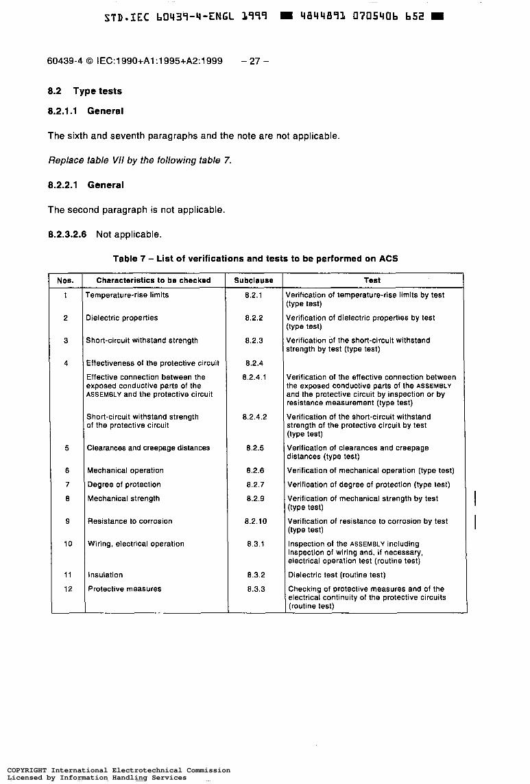
8.2 Type tests
8.2.1.1 General
The sixth and seventh paragraphs and the note are not applicable.
Replace table VI/ by the following table 7.
8.2.2.1 General
The second paragraph is not applicable.
8.2.3.2.6 Not applicable.
Table 7 - List of verifications and tests to be performed on ACS
Nos.
1
2
3
4
5
6
7
a
9
10
11
12
Characteristics to be checked
-emperature-rise limits
Xelectric properties
short-circuit withstand strength
Sffectiveness of the protective circuit
Iffective connection between the ?xposed conductive parts of the LSSEMBLY and the protective circuit
Short-circuit withstand strength 3f the protective circuit
Zlearances and creepage distances
Mechanical operation
Degree of protection
Mechanical strength
Resistance to corrosion
Wiring, electrical operation
Insulation
Protective measures
Subclause
8.2.1
8.2.2
8.2.3
8.2.4
8.2.4.1
a. 2.4.2
8.2.5
8.2.6
8.2.7
8.2.9
8.2.10
8.3.1
8.3.2
8.3.3
Test
lerification of temperature-rise limits by test type test)
Jerification of dielectric properties by test :type test)
Jerification of the short-circuit withstand strength by test (type test)
Jerification of the effective connection between :he exposed conductive parts of the ASSEMBLY and the protective circuit by inspection or by ?esistanCe measurement (type test)
Verification of the short-circuit withstand strength of the protective circuit by test (type test)
Verification of clearances and creepage distances (type test)
Verification of mechanical operation (type test)
Verification of degree of protection (type test)
Verification of mechanical strength by test (type test)
Verification of resistance to corrosion by test (type test)
Inspection of the ASSEMBLY including inspection of wiring and, i f necessary, electrical operation test (routine test)
Dielectric test (routine test)
Checking of protective measures and of the electrical continuity of the protective circuits (routine test)
COPYRIGHT International Electrotechnical CommissionLicensed by Information Handling ServicesCOPYRIGHT International Electrotechnical CommissionLicensed by Information Handling Services

- 28 - 60439-4 O CE11 1 990+A1: 1 995+A2: 1 999
de frappe I I ¡ E I - 1 : I I
PosRion de choc I
8.2.9 Verification de la resistance mécanique
8.2.9.1 Généralités
Echantlllon d'essai
a) Ces essais doivent être effectués sur tous les types d'EC, l'échantillon d'essai étant en ordre de fonctionnement mais séparé de son alimentation.
L'échantillon d'essai doit être entièrement dégagé de son emballage.
b) Les essais comportent deux épreuves distinctes: - essai d'impact;
- essai de choc.
-Y
Le constructeur doit indiquer la température ambiante pendant ces essais dans le rapport sur l'essai de type.
I 8.2.9.2 Essai d'impact
a) Principe
L'EC complet (avec tous les composants installés à l'intérieur de l'enveloppe) doit être soumis à une série d'impacts de 6 joules appliqués à l'enveloppe (et non aux composants qu'elle renferme) (voir 7.1.5).
Le matériel à essayer doit être fixé sur un support de rigidité suffisante pour limiter le déplacement de I'EC à 0,l mm sous l'effet de l'impact spécifié. Trois impacts successifs doivent être appliqués sur chaque face de I'EC à essayer au moyen soit:
1) d'une sphère massive d'acier poli d'environ 50 mm de diamètre et d'une masse de 500 f 25 g, qui tombe librement d'une hauteur de 1,2 m, en partant du repos, sur la surface montée horizontalement de l'enveloppe. La dureté de la sphère ne doit pas être inférieure à 50 HR ni supérieure à 58 HR, ou
2) d'une sphère d'acier similaire, suspendue par une corde et balancée comme un pendule, tombant d'une distance de 1,2 m dans le but d'appliquer un choc horizontal.
b) Méthode d'essai
'
Voir la figure 1.
Position de &Dart
I I
Surface de support rigide
de la pièce
Support arrière rigide \
l
Surface de support rigide 374/sw
Figure 1 - Essai d'impact utilisant la pièce de frappe
COPYRIGHT International Electrotechnical CommissionLicensed by Information Handling ServicesCOPYRIGHT International Electrotechnical CommissionLicensed by Information Handling Services

~
STD-IEC b0439-4-ENGL 1999 4844891, 0705408 425 m
position I I I € I - 1 ; 1 3
Striking I
60439-4 O IEC:1990+A1:1995+A2:1999 - 29 -
1
8.2.9 Verification of mechanical strength
Test sample
8.2.9.1 General
------
a) These tests shall be applied to all types of ACS, the test sample being in working order but disconnected from the sample supply.
The test sample shall be completely unpackaged.
b) The tests include two distinct procedures: - impact test;
- shock test.
The manufacturer shall state the ambient temperatures during these tests in the type test report.
I 8.2.9.2 Impact test
a) Principle
The complete ACS (with all components mounted inside) shall be subjected to a series of impacts of 6 joules applied to the enclosure (not to the components inside it) (see 7.1.5).
The equipment to be tested shall be fixed on a support of adequate rigidity to restrict movement of the ACS to 0,l mm under the effect of the prescribed impact. Three successive impacts shall be applied to each face of the ACS under test by means of either:
1) a solid smooth steel sphere approximately 50 mm in diameter and with a mass of 500 * 25 g, which shall be allowed to fall freely from rest through a vertical height of 1,2 m onto the enclosure surface held in a horizontal plane. The hardness of the sphere shall be not less than 50 HR and not more than 58 HR, or
2) a similar steel sphere, shall be suspended by a cord and swing as a pendulum in order to apply a horizontal impact, falling through a vertical distance of 1,2 m.
b) Method of test
See figure 1 .
Striking
Rigid supporting surface
y<\, element startLT , position
Rigid backing support \
374/w Rigid supporting surface
Figure 1 - Impact test using striking element
COPYRIGHT International Electrotechnical CommissionLicensed by Information Handling ServicesCOPYRIGHT International Electrotechnical CommissionLicensed by Information Handling Services

~~ ~ ~~ ~
STD.IEC b0439-4-ENGL L999 4844891 0705409 3bL
- 30 - 60439-4 O CEI:1990+A1:1995+A2:1999
L'essai au pendule peut également être effectué pour essayer les surfaces inclinées. Cependant, si cette position d'essai ne convient pas, la surface à essayer sera placée dans le plan horizontal en faisant tourner l'unité sur le support, ce qui permet d'effectuer l'essai selon 1). Avant chaque essai, on doit inspecter la surface de la sphère pour s'assurer qu'elle ne présente ni bavures, ni défauts.
La disposition d'essai doit être telle que les impacts soient appliqués en des endroits où ils sont susceptibles de révéler des faiblesses. Au total, 18 impacts doivent être appliqués à I'EC.
L'essai n'est pas applicable aux composants tels que socles de prises de courant, poignées de commande, voyants lumineux, boutons de contact, poussoirs, etc., lorsque ceux-ci, fixés sur les surfaces principales, sont en retrait de sorte que la distance entre les parties les plus exposées des composants et lesdites surfaces est d'au moins 1 cm.
Après l'essai, l'enveloppe doit offrir les degrés de protection spécifiés en 7.2.1.1. Aucune des déformations ou altérations de l'enveloppe ou des composants ne doit être préjudiciable au fonctionnement de I'EC, ni amener les distances d'isolement et les lignes de fuite en dessous des valeurs spécifiées. Les poussoirs, poignées, etc., doivent être en ordre de fonctionnement.
Des dégâts superficiels, l'écaillage de peinture, des bris de nervures de refroidissement ou de parties similaires, des fentes non visibles avec une vue normale ou corrigée par des verres et sans grossissement supplémentaire, et de légères craquelures n'entrainent pas le rejet.
c) Résultats
I 8.2.9.3 Essai de choc
a) Principe
L'EC doit être soumis à une seule demi-période sinusoïdale, l'essai de choc ayant une sévérité de 500 m/s2 (50 g) pour l'accélération de crête et une durée de 11 ms.
L'EC en ordre de fonctionnement doit être essayé conformément à la CE1 60068-2-27. Sous réserve d'un accord entre le constructeur et l'utilisateur, l'essai peut être effectué sur des colonnes séparées d'un EC.
Voir 8.2.9.2, alinéa c).
b) Méthode d'essai
c) Résultats
I 8.2.10 Vérification de la résistance à la corrosion
Pour la vérification de la résistance de I'EC à la corrosion, on effectue les essais suivants:
I 8.2.10.1 Vérification de la résistance à la corrosion dans des conditions normales d'emploi
a) Principe
L'EC complet doit être soumis a des variations de température et d'humidité en séjournant dans une enceinte climatique dans la position d'installation ou de montage recommandée.
b) Méthode d'essai et atmosphère d'essai L'essai comporte trois cycles d'une durée de 24 h chacun. Les variations de température et d'humidité pour chaque cycle sont indiquées sur la figure 2.
COPYRIGHT International Electrotechnical CommissionLicensed by Information Handling ServicesCOPYRIGHT International Electrotechnical CommissionLicensed by Information Handling Services

60439-4 O IEC:1990+A1:1995+A2:1999 - 31 -
Sloping surfaces may be tested using the pendulum but if this is not convenient the surface will be aligned in the horizontal plane by turning the unit on the support and the test 1) is used. Before each test an inspection of the sphere shall be made to ensure that it is free of burrs and defects.
The test shall be so arranged that the impacts are applied at positions where weaknesses are most likely to be revealed. A total of 18 impacts shall be applied to the ACS.
The test is not applicable to components such as socket-outlets, operating handles, illuminating lights, pushbuttons, actuators, etc., when these components are mounted in recesses with respect to the main surfaces, so that the distance between the most exposed parts of these components and the said surfaces is at least 1 cm.
After the test, the enclosure shall continue to provide the degrees of protection specified in 7.2.1.1 ; any distortions or deformations of the enclosure and components shall neither be detrimental to the proper functioning of the ACS nor decrease creepage distances and clearances to below the required values; actuators, handles, etc., shall still be operable.
Superficial damage, paint removals, breaking of cooling ribs or similar parts, small indentations, cracks not visible with normal or corrected vision without further magnifi- cation, or surface cracks shall not constitute failure of the test.
c) Results to be obtained
8.2.9.3 Shock test
a) Principle
The ACS shall be subjected to a single pulse half-sine wave, the shock test having a severity of 500 m/s2 (50 g) peak acceleration and a duration of 11 ms.
The ACS in working order shall be tested according to IEC 60068-2-27. Subject to agreement between manufacturer and user, the test may be carried out at separate sections of the ACS.
c) Results to be obtained
b) Method of test
As in 8.2.9.2, item c).
8.2.1 O Verification of resistance to corrosion I Resistance of the ACS to corrosion is verified by the following tests:
I 8.2.1 0.1
a) Principle
Verification of resistance to corrosion under normal service conditions
The complete ACS shall be exposed to temperature and humidity variations by being placed in a climatic chamber in the recommended installed or mounted position.
b) Method of test and test atmosphere The test is carried out in three cycles each lasting 24 h. The temperature and humidity variations for each cycle are defined in figure 2.
COPYRIGHT International Electrotechnical CommissionLicensed by Information Handling ServicesCOPYRIGHT International Electrotechnical CommissionLicensed by Information Handling Services

- 32 - 60439-4 O CEI:1990+A1:1995+A2:1999
"C
%
' O 0 t l I
i I I
O 2 4 6 8 10 12 14 16 18 20 22 2 6 h
Durée - 375190
Figure 2
c) Résultats
L'EC est considéré comme satisfaisant aux prescriptions si - aucune trace de corrosion n'est décelée ni à l'intérieur, ni à l'extérieur (exception faite
de la tranche des tôles);
- aucun effet dommageable dû à la condensation n'apparaît dans l'installation électrique, ce que l'on vérifie par application des essais décrits en 8.2.2.
I 8.2.10.2 Vérification de la résistance à la corrosion dans une atmosphère fortement polluée
Principe
Cet essai est destiné à évaluer les effets corrosifs d'une atmosphère industrielle, c'est-à- dire d'une atmosphère riche en anhydride sulfureux.
L'EC complet doit être exposé à cette atmosphère d'une manière continue pendant dix jours.
Méthode d'essai et atmosphère d'essai
L'EC en ordre de fonctionnement doit être essayé conformément à la CE1 60068-2-42.
Résultats à obtenir
L'EC est considéré comme satisfaisant aux prescriptions si - aucune trace de corrosion n'est décelée ni à l'intérieur, ni à l'extérieur (exception faite
de la tranche des tôles); - aucun effet dommageable n'apparaît dans l'installation électrique, ce que l'on vérifie
en effectuant, 24 h après avoir retiré I'EC de l'enceinte d'essai, les essais décrits en 8.2.2.
COPYRIGHT International Electrotechnical CommissionLicensed by Information Handling ServicesCOPYRIGHT International Electrotechnical CommissionLicensed by Information Handling Services

60439-4 O IEC:1990+A1:1995+A2:1999 - 33 -
I 1
Duration - 37ww
Figure 2
c) Results to be obtained
The ACS shall be declared satisfactory, if - no trace of corrosion is found either inside or outside (except for the sharp edges);
- no damaging effect due to condensation appears in the electric installation, verified by applying the tests of 8.2.2.
I 8.2.1 0.2 Verification of resistance to corrosion in a heavily polluted atmosphere
a) Principle
This test is intended to assess the corrosive effects of an industrial atmosphere, ¡.e. an atmosphere polluted with sulphur dioxide.
The complete ACS shall be continuously exposed to this atmosphere for ten days.
b) Method of test and test atmosphere The complete ACS shall be tested in accordance with IEC 60068-2-42.
c) Results to be obtained
The ACS is declared satisfactory, if - no trace of corrosion is found either inside or outside (except for the sharp edges);
- no damaging effect appears in the electric installation, verified by applying the tests of 8.2.2 24 h after the ACS has been removed from the test chamber.
COPYRIGHT International Electrotechnical CommissionLicensed by Information Handling ServicesCOPYRIGHT International Electrotechnical CommissionLicensed by Information Handling Services

- 34 - 60439-4 O CE111 990+A1:1995+A2:1999
1 8.2.10.3 Variante
En variante à l'essai de I'EC complet, les essais selon 8.2.10.1 et 8.2.10.2 peuvent être effectués sur un échantillon d'essai comportant au moins une unité de chacune de celles composant I'EC en cours d'évaluation ainsi que tous les matériels contenus dans celui-ci, ayant la même finition de surface et la même protection contre la corrosion et étant assemblé suivant les mêmes méthodes de construction électrique ou mécanique que ledit EC.
8.3.2 Essai diélectrique
I La dernière phrase ne s'applique pas.
8.3.4 Vérification de la résistance d'isolement
Ne s'applique pas.
9 Caractéristiques particulières des divers types fonctionnels d'EC
a) Deux ou plusieurs des ENSEMBLES détaillés de 9.1 à 9.5 inclus peuvent toujours être regroupés en un seul EC. Exemple: un ENSEMBLE de raccordement et de comptage et un ENSEMBLE de répartition générale.
c) Dans les limites indiquées ci-après, les courants assignés des divers types d'ENSEMBLES seront choisis de preference dans la série RENARD (voir tableaux VIII et IX de la
I b) La définition des divers types d'EC est donnée en 2.1 1 et 2.12.
CE1 60439-1).
NOTE Des exemples d'application sont données dans l'annexe F.
9.1
Cet ENSEMBLE comporte normalement
EC de raccordement et de comptage
- un compartiment recevant les équipements d'extrémité du câble d'arrivée et les équipements de comptage;
- les systèmes de coupure et de protection contre les surcharges et les courts-circuits du câble de départ.
Le compartiment mentionné ci-dessus doit avoir son propre accès (plaque de fermeture, volet, porte, etc.).
9.1.1 Unite d'arrivée
Les équipements de raccordement du câble (bornes exclusivement) doivent être compatibles avec le courant assigné de l'unité.
Un dispositif de séparation et un dispositif de protection contre les surintensités peuvent être prévus, notamment si le distributeur d'énergie électrique le demande.
9.1.2 Unité de comptage
Le système de comptage est défini par ou en accord avec le distributeur d'énergie.
COPYRIGHT International Electrotechnical CommissionLicensed by Information Handling ServicesCOPYRIGHT International Electrotechnical CommissionLicensed by Information Handling Services

STD-IEC b0439-4-ENGL 1999 W 4844891 0705434 729 m
60439-4 O IEC:1990+A1:1995+A2:1999 - 35 -
I 8.2.1 0.3 Alternative
As an alternative to testing the complete ACS, the tests in 8.2.10.1 and 8.2.10.2 may be made on a test sample equipment that comprises at least one of each type of unit contained in the ACS under assessment, and comprises all the materials, has the same surface finish and protection against corrosion, and has the identical electrical and mechanical construction to that of the ACS under assessment.
8.3.2 Dielectric test
The last sentence is not applicable
8.3.4 Verification of insulation resistance
Not applicable.
Particular features of the various functional types of ACS
Two or several of the ASSEMBLIES detailed from 9.1 to 9.5 inclusive may be grouped in one ACS. Example: an incoming supply and metering ASSEMBLY and a main distribution ASS EM B LY . The definitions of the various types of ACS are given in 2.1 1 and 2.12. I Within the limits indicated below, the rated currents of the various types of ASSEMBLY should preferably be selected from the RENARD series (see table VIII and IX of IEC 60439-1).
NOTE Examples of application are given in annex F.
9.1
This ASSEMBLY normally contains
Incoming supply and metering ACS
- a compartment with termination facilities for the incoming feeder cable and the metering;
- the overload and short-circuit current interruption and protection systems for the outgoing cable.
The above-mentioned compartment shall have its own means of access (cover plate, shutter, door, etc.).
9.1.1 Incoming unit
The cable connection facilities (terminals exclusively) shall be compatible with the current rating of the unit.
An isolating device and an over-current protective device may be provided particularly where specified by the electricity supply authority.
9.1.2 Metering unit
The metering system is to be designed by or in agreement with the electricity supply authority.
COPYRIGHT International Electrotechnical CommissionLicensed by Information Handling ServicesCOPYRIGHT International Electrotechnical CommissionLicensed by Information Handling Services

- 36 - 60439-4 O CEI:1990+A1:1995+A2:1999
9.1.3 Unité de départ
a) Des dispositifs pour la séparation, la coupure en charge et la protection contre les surintensités ainsi que les contacts indirects doivent être prévus. Ces fonctions peuvent être combinées en un ou plusieurs appareils.
b) Le système de séparation doit pouvoir être condamné en position ouverte (par exemple par un cadenas ou une installation à l'intérieur d'une enceinte verrouillable).
c) Le dispositif de coupure en charge doit être facilement accessible sans usage d'une clé ou d'un outil.
d) La coupure doit être simultanée sur tous les pôles et intéresser tous les conducteurs de phase. Pour la coupure du conducteur neutre, voir la CE1 60364-4-46.
9.2 EC de répartition générale
9.2.1 Organisation générale
Cet ENSEMBLE comporte une unité d'arrivée et plusieurs unités de départ.
9.2.2 Unité d'arrivée
Les équipements de raccordement du câble (bornes exclusivement) doivent être compatibles avec le courant assigné de l'unité. Un dispositif de séparation et un dispositif de protection contre les surintensités doivent être prévus. II doit être possible de condamner en position ouverte le dispositif de séparation. Toutefois, la protection contre les surintensités est facultative si I'ENSEMBLE de répartition générale est alimenté à partir d'un ENSEMBLE de raccordement et de comptage (voir 9.1).
Le courant assigné doit être au moins égal à 630 A.
9.2.3 Unité de départ
Chaque unité comporte un ou plusieurs circuits de départ. Les prescriptions données en 9.1.3 sont valables pour chacun d'eux, à l'exclusion toutefois du dispositif de condamnation en position ouverte de l'appareil de séparation, qui est facultatif.
9.3 EC de distribution
9.3.1 Organisation générale
Cet ensemble comporte une unité d'arrivée et plusieurs unités de départ.
9.3.2 Unité d'arrivée
Les équipements de raccordement du câble (bornes exlusivement) doivent être compatibles avec le courant assigné de l'unité. Un dispositif de séparation et une protection contre les surintensités doivent être prévus. Le dispositif de séparation doit pouvoir être condamné en position ouverte. La protection contre les surintensités est facultative si I'ENSEMBLE de distribution est à l'aval d'un ENSEMBLE de raccordement et de comptage (décrit en 9.1) ou d'un ENSEMBLE de répartition générale (décrit en 9.2).
Le courant assigné doit être supérieur à 125 A et ne doit pas dépasser 630 A.
COPYRIGHT International Electrotechnical CommissionLicensed by Information Handling ServicesCOPYRIGHT International Electrotechnical CommissionLicensed by Information Handling Services

60439-4 O IEC:1990+A1:1995+A2:1999 - 37 -
9.1.3 Outgoing unit
a) There shall be means for isolation, load switching, over-current protection and protection against indirect contact. These functions may be provided by one or more devices.
b) There shall be means for securing the isolating device(s) in the open position (for example a padlock or installation inside a lockable enclosure).
c) The load switching device shall be easily accessible without the use of a key or tool.
d) The switching device shall operate simultaneously on all poles and involve all the phase conductors. For switching the neutral conductor, see IEC 60364-4-46.
9.2 Main distribution ACS
9.2.1 General arrangement
This ASSEMBLY consists of one incoming unit and several outgoing units.
9.2.2 Incoming unit
The cable connection facilities (terminals exclusively) shall be compatible with the current rating of the unit. An isolating device and an overcurrent protective device shall be provided. There shall be means for securing the isolating device in the open position. However, the overcurrent protective device is optional if the t'nain distribution ASSEMBLY is supplied from an incoming supply and metering ASSEMBLY (see 9.1).
The rated current shall be at least 630 A.
9.2.3 Outgoing units
Each unit consists of one or more outgoing circuits. The requirements of 9.1.3 are applicable to each of them, with the exception, however, of the provision of means for securing the isolating device in the open position, which is optional.
9.3 Distribution ACS
9.3.1 General arrangement
This ACS consists of one incoming and several outgoing units.
9.3.2 Incoming unit
The cable connection facilities (terminals exclusively) shall be compatible with the current rating of the unit. An isolating device and an overcurrent protective device shall be provided and there shall be means for securing the isolating device in the open position. The overcurrent protective device is optional, if the distribution ASSEMBLY is on the load side of an incoming supply and metering ASSEMBLY (described in 9.1) or on the load side of a main distribution ASSEMBLY (described in 9.2).
The rated current shall be greater than 125 A and shall not exceed 630 A.
COPYRIGHT International Electrotechnical CommissionLicensed by Information Handling ServicesCOPYRIGHT International Electrotechnical CommissionLicensed by Information Handling Services

STD.IEC b0439-4-ENGL 3999 = 4844891 0705417 438 =
- 38 - 60439-4 O CEI:1990+A1:1995+A2:1999
9.3.3 Unité de départ
Chaque unité comporte un ou plusieurs circuits de départ. Les prescriptions données en 9.1.3 sont valables pour chaque câble, à l'exclusion toutefois du dispositif de condamnation en position ouverte de l'appareil de séparation, qui est facultatif.
Les câbles de départ peuvent être raccordés soit par bornes, soit par des socles de prises de courant. Les socles de prise de courant dont le courant assigné ne dépasse pas 32 A, normalement destinés au branchement d'outils électriques à main et appareils analogues, doivent être protégés par des dispositifs de protection à courant résiduel ayant un courant différentiel de fonctionnement assigné de 30 mA au maximum. Plusieurs circuits de socles de prise de courant peuvent être protégés par le même appareil à courant résiduel.
Pour les schémas IT, un appareil à courant résiduel pour chaque socle de prises de courant est nécessaire.
En variante, les socles de prise de courant peuvent être alimentés à partir d'un système très basse tension selon la CE1 60364.
Les socles de prise de courant, autres que ci-dessus, doivent être protégés selon la réglementation nationale.
9.4 EC de transformation
9.4.1 Organisation générale
Cet ENSEMBLE doit être constitué d'une unité d'arrivée et peut comprendre une unité de transformation Basse Tension/ Très Basse Tension (BTTTBT) et, le cas échéant, une ou plusieurs unités de transformation Basse Tension/Basse Tension (BT/BT).
9.4.2 Unité d'arrivée
Les prescriptions données en 9.3.2 s'appliquent, mais le courant assigné étant au plus égal à 630 A.
9.4.3 Unité BT/TBT
Cette unité peut être soit du type BTTTBTF, soit du type BTTTBTS et la valeur assignée de la tension secondaire ne doit pas excéder la limite supérieure du domaine I (voir CE1 60364-4-41).
9.4.3.1 Unité BT/TBTS
Ce type d'unité comporte essentiellement:
a) les dispositifs de protection et de commande sur le circuit primaire;
b) le transformateur BTTTBT qui doit être à enroulements séparés, assurant de ce fait la séparation entre les circuits primaire et secondaire, et dont la tension assignée du primaire n'est pas supérieure a 1 O00 V. Ce transformateur doit être conforme à la CE1 60742;
c) les systèmes de protection et de commande du ou des câbles de départ (un seul départ si I'EC est du type mobile).
En ce qui concerne le câblage a tres basse tension de ce type d'unité, les règles du 41 1 .1.3: Conditions d'installation des circuits, de la CE1 60364-4-41, s'appliquent.
COPYRIGHT International Electrotechnical CommissionLicensed by Information Handling ServicesCOPYRIGHT International Electrotechnical CommissionLicensed by Information Handling Services

~~ ~ ~ ~
STD-IEC b0439-4-ENGL 3999 4844893 0705438 374 E
60439-4 O IEC:1990+A1:1995+A2:1999 - 39 -
9.3.3 Outgoing units
Each unit consists of one or several outgoing circuits. The requirements specified in 9.1.3 apply to each feeder, except, however, that means for securing the isolating device in the open position is optional.
Outgoing cables may be connected either to terminals or to socket-outlets. Socket-outlets with current ratings not exceeding 32 A, normally used for connection of electrically driven hand- held tools and similar portable appliances, shall be protected by residual current operated protective devices with a rated residual operating current not exceeding 30 mA. Several socket-outlet circuits may be protected by the same residual current device.
For IT systems, one residual current device for each socket-outlet is necessary.
Alternatively, socket-outlets may be supplied from an appropriate reduced low-voltage system in accordance with IEC 60364.
Socket-outlets other than the above shall be protected in accordance with national regulations.
9.4 Transformer ACS
9.4.1 General arrangement
This ASSEMBLY shall consist of an incoming unit and may include a low voltage/extra-low voltage (LV/ELV) transformer unit and, possibly, one or more low voltage/low voltage (LV/LV) transformer units.
9.4.2 Incoming unit
The requirements of 9.3.2 apply except that the current rating shall not exceed 630 A.
I 9.4.3 LVIELV unit
This unit may be either of the LV/FELV type or of the LV/SELV type and the rated secondary voltage shall not exceed the upper limit of voltage band I (see IEC 60364-4-41).
9.4.3.1 LV/SELV unit
This type of unit mainly consists of:
a) the protective and control devices in the primary circuit;
b) the LV/SELV transformer which shall have separate windings, thus ensuring isolation between the primary and the secondary circuits at primary rated voltage not exceeding 1 O00 V. This transformer shall be in accordance with IEC 60742;
c) the protective and control systems for the outgoing cable(s) (one output only if the ACS is mob i le).
For the ELV wiring of this type of unit the requirements of 41 1.1.3: Arrangement of circuits, of IEC 60364-4-41, apply.
COPYRIGHT International Electrotechnical CommissionLicensed by Information Handling ServicesCOPYRIGHT International Electrotechnical CommissionLicensed by Information Handling Services

STD.IEC b0439-4-ENGL 1999 = 4844891 0705439 200
- 40 - 60439-4 O CEI:1990+A1:1995+A2:1999
9.4.3.2 Unité BTiTBTF
Ce type d'unité comporte essentiellement:
a) les dispositifs de protection et de commande sur le circuit primaire;
b) le transformateur BTTTBTF, qui doit être conforme à la CE1 60076;
c) le conducteur de mise à la terre du circuit secondaire (relié à celui du circuit primaire);
d) les systèmes de protection et de commande du câble de départ (raccordement par socle de prise de courant).
En ce qui concerne le câblage à tres basse tension de ce type d'unité, les règles du 41 1.3: Très basse tension fonctionnelle, de la CE1 60364-4-41, s'appliquent.
9.4.4 Unités BT/BT
Chaque unité BT/BT comporte essentiellement:
a) les dispositifs de protection et de commande sur le circuit primaire;
b) le transformateur BT/BT, qui doit être un transformateur de séparation conforme à la CE1 60742;
c) les dispositifs de protection et de commande pour les circuits secondaires; d) les départs par bornes ou socles de prise de courant. Les socles de prise de courant
doivent être protégés comme cela est exigé en 9.3.3.
Nonobstant l'alinéa b), le transformateur pourra ne pas être un transformateur de séparation si le point neutre est raccordé par un conducteur à une borne de mise à la terre extérieure à l'enveloppe. Ce conducteur doit être identifié par une étiquette placée à l'intérieur de l'enveloppe, le plus pres possible de la borne. Dans ce cas, les prescriptions des alinéas a), c) et d) s'appliquent également.
I
9.5 EC terminai d'alimentation
9.5.1 Unite d'arrivée
Le câble d'arrivée doit être raccordé par bornes ou dispositifs d'entrées (prises mobiles) compatibles avec le courant assigné de l'unité. Celui-ci ne doit pas être supérieur à 125 A.
Pour le reste, cette unité doit être en conformité avec le 9.3.2.
9.5.2 Unité de depart
Chaque unité comporte un ou plusieurs câbles de départ. Les prescriptions indiquées en I 9.3.3 s'appliquent.
Si ('ENSEMBLE terminal d'alimentation est directement incorporé à l'un des ENSEMBLES mentionnés en 9.1, 9.2, 9.3, 9.4, la prescription ci-dessus est valable pour l'appareil à courant résiduel situé immédiatement à l'amont et l'unité d'arrivée de I'ENSEMBLE terminal d'alimentation peut alors être supprimée.
COPYRIGHT International Electrotechnical CommissionLicensed by Information Handling ServicesCOPYRIGHT International Electrotechnical CommissionLicensed by Information Handling Services

~ ~
STD-IEC b0439-4-ENGL 3999 M 4844891 0705420 T Z 2 M
60439-4 O IEC:1990+A1:1995+A2:1999 - 41 -
9.4.3.2 LVIFELV unit
This type of unit mainly consists of:
a) the protective and control devices on the primary circuit:
b) the LV/FELV transformer, which shall be in accordance with IEC 60076;
c) the earthing conductor of the secondary circuit (connected to that of the primary circuit);
d) the protective and control systems for the outgoing cable (connection by socket-outlet).
For the ELV wiring of this type of unit the requirements of Clause 411.3: Functional extra-low voltage, of IEC 60364-4-41, apply.
9.4.4 LVILV units
Each LV/LV unit consists essentially of:
a) the protective and control devices on the primary circuit; b) the LV/LV transformer, which shall be an isolating transformer in accordance with
IEC 60742;
c) the protective and control devices for the secondary circuits; d) the outlets, either terminals or socket-outlets. Socket-outlets shall be protected as I
required in 9.3.3.
Notwithstanding paragraph b) the transformer need not be an isolating transformer if the neutral point is connected by a cable to an earthing terminal outside the enclosure. This cable shall be identified by a label placed inside the enclosure as close as possible to the terminal. Also in this case requirements a), c) and d) apply.
9.5 Final distribution ACS
9.5.1 Incoming unit
The incoming cable shall be connected to terminals or input devices (connectors) compatible with the current rating of the unit. The latter shall be not greater than 125 A.
In all other respects, this unit shall be in accordance with 9.3.2.
9.5.2 Outgoing unit
Each unit comprises one or several outgoing cables. The requirements of 9.3.3 apply. I If the final distribution ASSEMBLY is directly incorporated in one of the ASSEMBLIES referred to in 9.1, 9.2, 9.3, 9.4, the above provision is valid for the residual-current device situated immediately on the supply side and the incoming unit of the final distribution ASSEMBLY may then be omitted.
COPYRIGHT International Electrotechnical CommissionLicensed by Information Handling ServicesCOPYRIGHT International Electrotechnical CommissionLicensed by Information Handling Services

- 42 - 60439-4 O CEI:1990+A1:1995+A2:199!3
9.6 EC de prises de courant
L'ENSEMBLE de prises de courant doit être de l'un des deux types suivants:
a) soit du type ayant des tensions assignées d'emploi égales ou supérieures à la tension assignée de l'alimentation et des fréquences assignées fixées par les réglementations nationales;
b) soit du type ayant des tensions d'emploi réduites ou des fréquences différentes de celles du réseau d'alimentation.
Cet ENSEMBLE est soit mobile, soit transportable et contient normalement les unités fonctionnelles suivantes:
9.6.1 Unité d'arrivée
L'arrivée est réalisée soit par l'intermédiaire d'un câble souple fixe avec fiche, soit au moyen d'un dispositif de connexion. Cette fiche ou le dispositif de connexion seront accouplés avec
I un socle ou un dispositif de connexion correspondant disposé sur l'unité d'alimentation. Le courant assigné ne doit pas dépasser 63 A.
9.6.2 Unité de départ BT ou TBT
Les câbles de départ doivent être connectés exclusivement par socles de prises de courant. Chacun de ceux-ci doit avoir sa propre protection contre les surcharges, a moins que la fiche du câble d'arrivée qui alimente l'ensemble des socles de prises de courant à partir de I'ENCEMBLE de distribution ait un courant assigne egal au plus faible des courants assignés des socles de prises de l'unité. Dans ce cas, la protection contre les surcharges doit être choisie pour le courant assigné le plus faible.
I Les socles de prise de courant doivent être protégés comme cela est exigé en 9.3.3.
COPYRIGHT International Electrotechnical CommissionLicensed by Information Handling ServicesCOPYRIGHT International Electrotechnical CommissionLicensed by Information Handling Services

~ ~ ~
~
STD=IEC b0439-4-ENGL 1999 D 4844891 0705422 8T5 0
60439-4 O IEC:1990+A1:1995+A2:1999 - 43 -
9.6 Socket-outlet ACS
The socket-outlet ASSEMBLY shall be one of the two following types:
a) either with rated operational voltages not less than the nominal supply voltages and rated frequencies in accordance with the national regulations;
b) or lower operational voltages or frequencies differing from those of the power supply.
This ASSEMBLY is either mobile or transportable and normally contains the following functional units.
9.6.1 Incoming unit
The incoming flexible cable shall be connected either by a plug or a connecting device. This I plug or connecting device will connect with a matching socket-outlet or connecting device mounted on the supply unit. The rated current shall not exceed 63 A. I 9.6.2
The outgoing cables shall be connected solely by cocket-outlets. Each of the latter shall have its own overload protection unless the plug on the incoming cable that supplies the socket- outlets as a whole, from a distribution ASSEMBLY has a rated current equal to the lowest of the rated currents of the socket-outlets in the unit. In that case, the overload protection shall be selected for the lowest current rating.
Outgoing unit, LV or ELV
I Socket-outlets shall be protected as required in 9.3.3. I
COPYRIGHT International Electrotechnical CommissionLicensed by Information Handling ServicesCOPYRIGHT International Electrotechnical CommissionLicensed by Information Handling Services
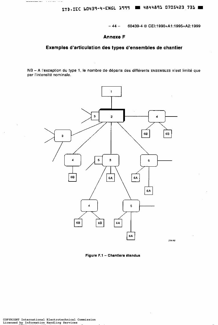
- 44 - 60439-4 O CEI:1990+A1:1995+A2:1999
Annexe F
Exemples d'articulation des types d'ensembles de chantier
NB - A l'exception du type 1, le nombre de départs des différents ENSEMBLES n'est limité que par l'intensité nominale.
/
El 3?6/W
Figure F.l - Chantiers étendus
COPYRIGHT International Electrotechnical CommissionLicensed by Information Handling ServicesCOPYRIGHT International Electrotechnical CommissionLicensed by Information Handling Services

~
STD.IEC b0439-4-ENGL 1999 M 4844893 0705424 b78 m
60439-4 O IEC:1990+A1:1995+A2:1999 - 45 -
Annex F
Interconnection of types of ACS: examples
NB - With the exception of Type 1, the number of outlets of the different ASSEMBLIES is limited only by the current rating.
Figure F.l - Large sites
376/9û
COPYRIGHT International Electrotechnical CommissionLicensed by Information Handling ServicesCOPYRIGHT International Electrotechnical CommissionLicensed by Information Handling Services

378/90
Figure F.2 - Chantiers de moyenne ou faible importance
COPYRIGHT International Electrotechnical CommissionLicensed by Information Handling ServicesCOPYRIGHT International Electrotechnical CommissionLicensed by Information Handling Services

~ ~
STD-IEC b0439-4-ENGL 1999 R 4844893 070542b 440
60439-4 O IEC:1990+A1:1995+A2:1999 - 47 -
377f90
378/90 1""1 379/90
Figure F.2 - Medium-sized or small sites
COPYRIGHT International Electrotechnical CommissionLicensed by Information Handling ServicesCOPYRIGHT International Electrotechnical CommissionLicensed by Information Handling Services

- 48 - 60439-4 O CE1:1990+A1:1995+A2:1999
Légende:
ENSEMBLE de raccordement et de comptage
U, = 2201380 ou 240/415 ou valeur préférentielle 230/400 V
ENSEMBLE de répartition générale
U, = 220/380 ou 240/415 ou valeur préférentielle 230/400 V
I , 2 630 A
ENSEMBLE de distribution
U, = 220/380 ou 240/415 ou valeur préférentielle 230/400 V
125 A c 1,s 630 A
ENSEMBLE de transformation
I , 5 630 A
U, , = 220 ou 240 ou valeur préférentielle 230 V
U,, = 24*, 48*, 60 OU 1 1 O* V
ENSEMBLE terminal d’alimentation
U, = 2201380 ou 240/415 ou valeur préférentielle 230/400 V
1,s 125 A
ENSEMBLE de prises de courant
Type 6A ou 6B
I , 5 63 A
Valeurs préférentielles (voir CE1 60038, sixierne édition).
COPYRIGHT International Electrotechnical CommissionLicensed by Information Handling ServicesCOPYRIGHT International Electrotechnical CommissionLicensed by Information Handling Services

STD-IEC b0439-4-ENGL 1999 11844891 0705428 213 0
60439-4 O IEC:1990+A1:1995+A2:1999 - 49 -
Key:
1 Supply incoming and metering ASSEMBLY
U, = 220/380 or 240/415 or preferred value 230/400 V
2 Main distribution ASSEMBLY
U, = 220/380 or 240/415 or preferred value 230/400 V
I, 2 630 A
3 Distribution ASSEMBLY
U, = 220/380 or 240/415 or preferred value 230/400 V
1 2 5 A < 1,5630A
4 Transformer ASSEMBLY
I, 5 630 A
U,, = 220 or 240 or preferred value 230 V
U,, = 24*, 48’, 60 or 1 1 O’ V
5 Final distribution ASSEMBLY
U, = 220/380 or 240/415 or preferred value 230/400 V
I, I 125 A
6 Socket-outlet ASSEMBLY
Type 6A or 6B I l I , I 63 A
* Preferred values (see IEC 60038, Sixth edition)
~ ~~ ~ ~~
COPYRIGHT International Electrotechnical CommissionLicensed by Information Handling ServicesCOPYRIGHT International Electrotechnical CommissionLicensed by Information Handling Services

I I I I I I I I I I I
' I I I I
¡ I I
STD-IEC 60439-4-ENGL 1999 m 4844891 0705429 I S T
The IEC would like to offer you the best quality standards possible. To make sure that we continue to meet your needs, your feedback is essential. Would you please take a minute to answer the questions overleaf and fax them to us at +41 22 919 03 O 0 or mail them to the address below. Thank you!
Customer Service Centre (CSC)
International Electrotechnical Commission 3, rue de Varembé 121 1 Genève 20 Switzerland
or
Fax to: IECKSC at +41 22 919 03 O0
Thank you for your contribution to the standards-making process.
I I I I I I I I I I
- - - _ _ _ _ _ _ _ _ _ _ _ _ _ _ _ - - - - . - . . .___ . ._ .__- - -____._______ Nicht frankieren Ne pas affranchir 1 Non aff rancare No stamp required
REPONSE PAYÉE
SUISSE
Customer Service Centre (CSC) Internat ional Elect rotec h n ical Commission 3, rue de Varembé 1211 GENEVA 20 Switzerland
COPYRIGHT International Electrotechnical CommissionLicensed by Information Handling ServicesCOPYRIGHT International Electrotechnical CommissionLicensed by Information Handling Services

Ql Please report on ONE STANDARD and Q6 ONE STANDARD ONLY. Enter the exact number of the standard: (e.g 60601-1-1)
.............................................................
Q2 Please tell us in what capacity(ies) you bought the standard (tick all that apply). I am the/a:
purchasing agent librarian researcher design engineer safety engineer testing engineer marketing specialist other ..........................
43 I work for/in/as a: (tick all that apply)
.... ..........
P P P
Q7 P o P
, .............
manufact u ring P consultant P government P test/certification facility P public utility o education military
P P
other ..................................................... Q8
Q4 This standard will be used for: (tick all that apply)
general reference LI product research P product design/development P specifications P Q9 tend ers P quality assessment P certif ¡cat ion 0 technical documentation D thesis LI manufacturing D other .....................................................
Q5 This standard meets my needs: (tick one)
not at all nearly fairly well exactly
If you ticked NOT AT ALL in Question 5 the reason is: (tick all that apply)
standard is out of date standard is incomplete standard is too academic standard is too superficial title is misleading I made the wrong choice other ............................... .. ......
Please assess the standard in the following categories, using the numbers: (1) unacceptable, (2) below average, (3) average, (4) above average, (5) exceptional, (6) not applicable
P P P D P o
......
timeliness .............................................
tech n ¡cal con tents ................................. logic of arrangement of contents .......... tables, charts, graphs, figures ............... other ....................................................
quality of writing ....................................
I r e a d h e the: (tick one)
French text only LI English text only o both English and French texts P
Please share any comment on any aspect of the IEC that you would like us to know:
............................................................
............................................................
............................................................
............................................................
............................................................
............................................................
............................................................
............................................................
............................................................
............................................................
............................................................
............................................................
I I I I I I I I I I I I I I l I I I I I I I I I I I I I I I I I I
k I I COPYRIGHT International Electrotechnical Commission
Licensed by Information Handling ServicesCOPYRIGHT International Electrotechnical CommissionLicensed by Information Handling Services

I I I I I I I I I I I I I I I I I I
STD.IEC 60439-4-ENGL 3999 4844893 0705433 808
a La CE1 ambitionne de vous offrir les meilleures normes possibles. Pour nous assurer que nous continuons a répondre a votre attente, nous avons besoin de quelques renseignements de votre part. Nous vous demandons simplement de consacrer un instant pour répondre au questionnaire ci-après et de nous le retourner par fax au +41 22 919 03 O0 ou par courrier a l’adresse ci-dessous. Merci !
Centre du Service Clientèle (CSC)
Commission Elect rotec h niq ue Internat ionale 3, rue de Varembé 121 1 Genève 20 Suisse
ou
Télécopie: CEI/CSC +41 22 919 03 O0
Nous vous remercions de la contribution que vous voudrez bien apporter ainsi à la Normalisation Internationale.
I I I
Nicht frankieren Ne pas affranchir I
I Non aff rancare I I No stamp required
I I I I I I I I I I I
REPONSE PAYEE SUISSE
Centre du Service Clientèle (CSC) Commission Electrotechnique Internationale 3, rue de Varembé
Suisse 121 1 GENEVE 20
R COPYRIGHT International Electrotechnical CommissionLicensed by Information Handling ServicesCOPYRIGHT International Electrotechnical CommissionLicensed by Information Handling Services

Ql Veuillez ne mentionner qu’UNE SEULE Q5 Cette norme répond-elle à vos besoins: NORME et indiquer son numéro exact: (ex. 60607-7-7)
(une seule réponse)
pas du tout 0 à peu près cl assez bien o parfaitement P
.............................................................
Q2 En tant qu’acheteur de cette norme, quelle est votre fonction? (cochez tout ce qui convient) Je suis lehn:
agent d’un service d’achat bibliothécaire chercheur ingénieur concepteur ingénieur sécurité ingénieur d’essais spécialiste en marketing autre(s). ................................
Je travaille: (cochez tout ce qui convient)
....
dans l’industrie comme consultant pour un gouvernement pour un organisme d’essais/
dans un service public dans l’enseignement comme militaire autre@) ....................................
ce rtif ¡cat ion
.........
LI o D P cl O P
.....
P O o
0 P P P
..............
Q4 Cette norme sera utilisée pour/comme (cochez tout ce qui convient)
ouvrage de référence P une recherche de produit O une étude/développement de produit O des spécifications o des soumissions o une évaluation de la qualité LI une certification o une documentation technique P une thèse P la fabrication P autre@). ................................................
Q6 Si vous avez répondu PAS DU TOUT à 05, c’est pour la/les raison(s) suivantes: (cochez tout ce qui convient)
la norme a besoin d’être révisée P la norme est incomplète o la norme est trop théorique LI la norme est trop superficielle P le titre est équivoque P je n’ai pas fait le bon choix o aut re(s) ................................................
Q7 Veuillez évaluer chacun des critères ci- dessous en utilisant les chiffres (1) inacceptable, (2) au-dessous de la moyenne,
(4) au-dessus de la moyenne, (5) exceptionnel, (6) sans objet
(3) moyen,
publication en temps opportun .............. qualité de la rédaction ........................... contenu technique ................................ disposition logique du contenu .............. tableaux, diagrammes, graphiques,
figures ................................................ autre(s) ................................................
48 Je lis/utilise: (une seule réponse)
uniquement le texte français ci uniquement le texte anglais o les textes anglais et français O
Q9 Veuillez nous faire part de vos observations éventuelles sur la CEI:
............................................................
............................................................
............................................................
............................................................
............................................................
............................................................
I I I I I I I I I I I I I I I I I I I I I I I I I I I I I I I I I I k I I COPYRIGHT International Electrotechnical Commission
Licensed by Information Handling ServicesCOPYRIGHT International Electrotechnical CommissionLicensed by Information Handling Services

ISBN 2-831 8-4851 -2
I ICs 29.130.20
Typeset and printed by the IEC Central Office GENEVA, SWITZERLAND
COPYRIGHT International Electrotechnical CommissionLicensed by Information Handling ServicesCOPYRIGHT International Electrotechnical CommissionLicensed by Information Handling Services