cdma principles
TRANSCRIPT

CDMA PRINCIPLES
ECE 2526 - MOBILE COMMUNICATION
Tuesday, 12 October 2021


SAMSUNG DUOS SPECIFICATIONS

SECOND GENERATION TECHNOLOGIES
1ST GENERATION 2ND GENERATION
CDMA1. IS-95 (CDMAOne)
FDMA/TDM-BASED SYSTEMS
1. GSM (European Standard)2. DAMPS/IS 136 - US Standard)3. PDC – Personal Digital Service (Japanese
Standard)
FDMA – BASED SYSTEMS1. AMPS (US Standard)2. ETACS (UK Standard)3. NMT (Nordic Countries)

CODE DIVISION MULTIPLE ACCESS (CDMA)
1. Code Division Multiple Access (CDMA) also known as IS-95 is a spread spectrum technology platform that enables multiple users to occupy the same radio channel or frequency spectrum at the same time.
2. Each CDMA Mobile Station (MS) employs its own unique code to distinguish it from other MSs.
3. CDMA Offers users all features associated with spread spectrum communication which include:a) Ability to thwart interference
b) Improved immunity to multipath effects
c) Anti-jam

HISTORY OF CDMA
• Motivation
• CDMA was intended as a new system (greenfield) or replacement for AMPS (not an upgrade) to
a) Increase system capacityb) Increase securityc) Add new features/services
• History: • 1990: Qualcomm proposed a code division multiple access (CDMA) digital cellular
system claimed to increase capacity by factor 20 or more – Started debate about how CDMA should be implemented and the advantages over TDMA.
• 1992: Telecommunication Industry Association (TIA) starts a study of spread spectrum cellular
• 1995: First CDMA system (named CDMA-one) launched in Hongkong

TYPES OF CDMA SYSTEMS
Narrow band (2 MHz)
CDMA 2000IS95 (CDMA-one) IS95BJ-STD 008
Wide Band5 MHz
CDMA
WCDMA/UMTS
Launch date: 1999Frequency Band: 800 & 1900 MHzData rate: 115 Kbps
Launch date: 1995Frequency Band: 800 MHzChip rate: 1,228,800 bits/sData rate: 14.4 Kbps
ANSI Standard Published – 1996Frequency Band: 800 & 1900 MHz

CDMA(IS-95) ARCHITECTURE
(a) CDMA Architecture
(b) GSM Architecture
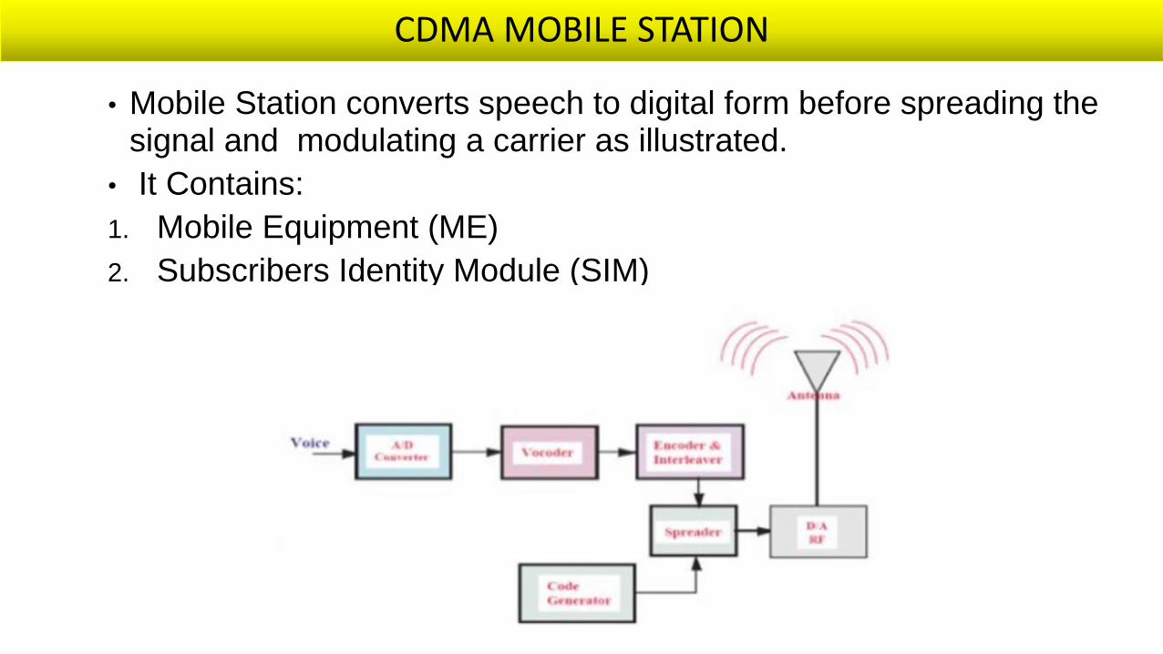
CDMA MOBILE STATION
• Mobile Station converts speech to digital form before spreading the signal and modulating a carrier as illustrated.
• It Contains:
1. Mobile Equipment (ME)
2. Subscribers Identity Module (SIM)

FUNCTIONS OF THE CDMA BTS
• It defines the cell .
• It handles the radio link protocol with the mobile station
• All CDMA base stations transmit on the same frequency.
• Similarly, all CDMA phones transmit on the same frequency.

FUNCTIONS OF THE CDMA MSC
The functions of the MSC in a CDMA network are:
1. Call set up/supervision/release
2. Call routing
3. Billing
4. Mobility management
5. Paging, connection to BSC, other MSC and other local exchange networks
6. Access to HLR and VLR
7. Access to other MSCs and the Public Switched Telephone Network (PSTN)

PROPERTIES/FUNCTIONS OF THE CDMA HLR
1. One HLR per CDMA operator
2. Contains permanent database of all the subscribers in the network
3. Contains MSRN(mobile station routing no.)

FUNCTIONS OF THE CDMA BSC
1. It manages radio resources for one or more BTS.
2. Allocation and Deallocation of channels.
3. Transmitter power control.
4. Handoff control
BSC

COMPARISON OF FDM/TDM SYSTEMS & CDMA
1. In TDMA Bandwidth available per channel is small which leads to compromise in quality of transmission. Whereas in CDMA systems entire bandwidth is used which enhances voice quality.
2. In TDMA/FDMA, cell design requires more frequency planning which is tough job. Whereas in CDMA frequency planning is minimal.
3. TDMA is bandwidth-limited system while CDMA is power-limited system

FEATURES OF CDMA
1. Frequency reuse of one
2. Tight power control
3. Longer battery life
4. Support for soft handoff

ADVANTAGES OF CDMA
1. High capacity without hard blocking limits
2. Easy frequency planning
3. Greater coverage with fewer cells
4. Technology platform extendable to new services
5. Excellent call quality
6. Inherent privacy
7. Lower power/Longer battery life

DISADVANTAGES OF CDMA
• Near far problem.
• CDMA can not offer international roaming, a large GSM advantage

DIRECT SEQUENCE/PSEUDO NOISE TRANSMITTER – FROM REVIOUS CLASS
• In Direct Sequence(also called a Pseudo-noise), the signal is generated by adding a binary message with the output of a pseudo-noise generator as shown below:
Binary
AdderBalanced
Modulator
Carrier
𝑓𝑐
Pseudo-noise
Generator
Clock
Message
Output

CDMA PRINCIPLE
Message signal
Pseudo Code
+
Each bit of sequence 1 is replaced
by the code sequence
Output
Rate of Change Known as bitrate
Rate of Change Known
as chiprate

BASE STATIONS – PN SEQUENCIES, TIMING
• All base stations use same PN sequence
• Each base station selects from 512 different PN off-sets
• Mobile station synchronizes to a pilot channel
• Each base station has GPS receiver to synchronize self with other bases stations
• Timing accuracy is vital to CDMA system functionality

GSM AND CDMA LINK DESIGNATION
(a) CDMA Um interface link designation
(b) GSM um Interface Link designation

MOBILE STATION CODES
1. Channelized by digital codes called long codes masked by a unique user long code mask
2. Long code is a 42 bit number - 242 billion combinations
3. Each mobile has a different long code mask
4. Two types of reverse channels:a) Traffic channels
b) Control/access channels

FORWARD CHANNELIZATION
Each bit of voice data is ‘spread’ by a factor of 64
XOR
Walsh code
generator1.2288 mcps
Output
Walsh coded
data
1.2288 mcps
Encoded
voice
data

REVERSE CHANNELIZATION
XOR
Masked Long Code
Data1.2288 mcps
Output
Long coded
data
1.2288 mcps
Walsh
modulated
voice data


COMPARISON OF 2G TECHNOLOGIES
Feature AMPS D-AMPS GSM CDMA
Frequency Band 800 MHz 800 & 1900 MHz 900 & 1800 MHZ 800 & 1900 MHz
Channel Width 30 KHz 30 KHz 200 KHz 1.25 MHz
Users per Channel
1 3 8 About 20
Multiplex Scheme
FDMA FDMA & TDMA FDMA & TDMA CDMA
Network Architecture
IS-41 IS-41 GSM-MAP(MAP-Mobile Application Part)
IS-41