ofdm-cdma. outline ofdm-cdma - introduction ofdm-cdma system conceptual implementation coding papr...
TRANSCRIPT
OFDM-CDMA
Outline
OFDM-CDMA - Introduction OFDM-CDMA system Conceptual Implementation Coding PAPR in OFDM-CDMA Systems Multi-antenna OFDM-CDMA Comparison with Other Technologies
OFDM-CDMA vs. MC-CDMA OFDM-CDMA vs. MC-DS-CDMA
Conclusion References
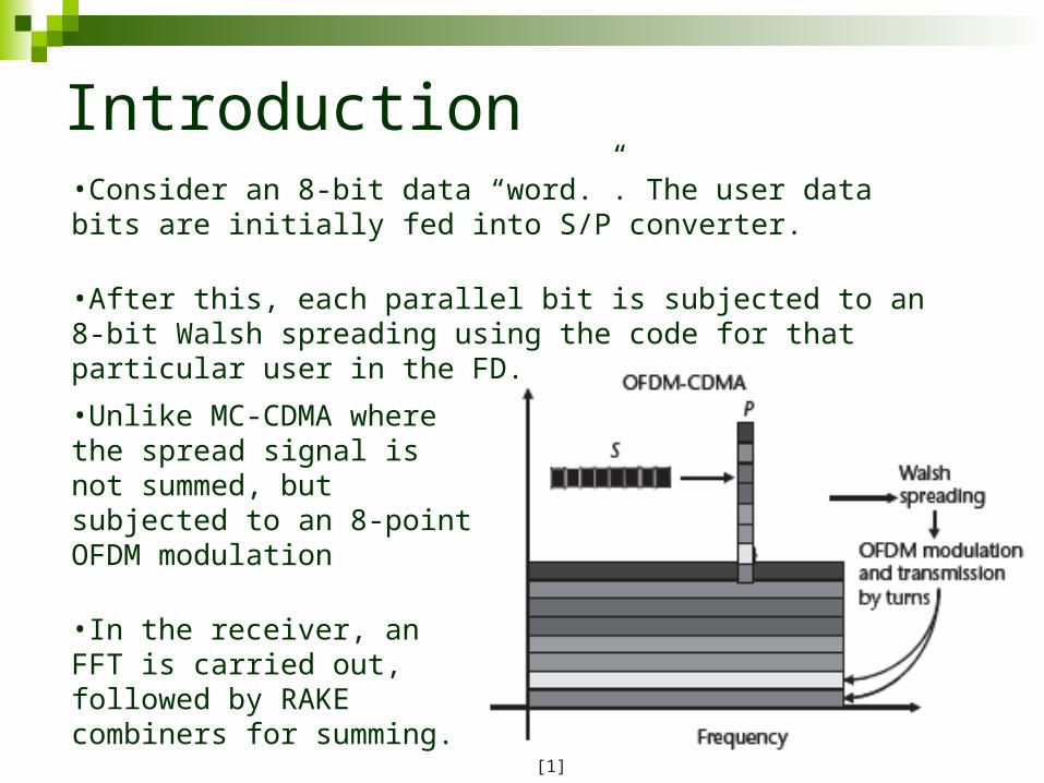
Introduction•Consider an 8-bit data “word.”. The user data bits are initially fed into S/P converter.
•After this, each parallel bit is subjected to an 8-bit Walsh spreading using the code for that particular user in the FD.
•Unlike MC-CDMA where the spread signal is not summed, but subjected to an 8-point OFDM modulation
•In the receiver, an FFT is carried out, followed by RAKE combiners for summing.
[1]
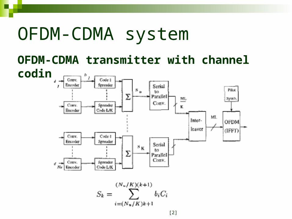
OFDM-CDMA systemOFDM-CDMA transmitter with channel coding
[2]
OFDM-CDMA system (contd.)
From each sub-system M data bits are serial to parallel converted producing ML / K parallel output streams of duration MTb seconds.
These streams are sent to the frequency interleaver which scrambles all of the outputs and passes them onto the OFDM modulator.
The frequency interleaver attempts to separate chips from the same data bit further apart than the coherence bandwidth to achieve frequency diversity. The total number of carriers is ML.
Finally a guard interval ∆, is inserted which is longer than the delay spread in the channel to prevent ISI and ICI. This gives a total symbol duration of T = MTa + ∆.
[2]
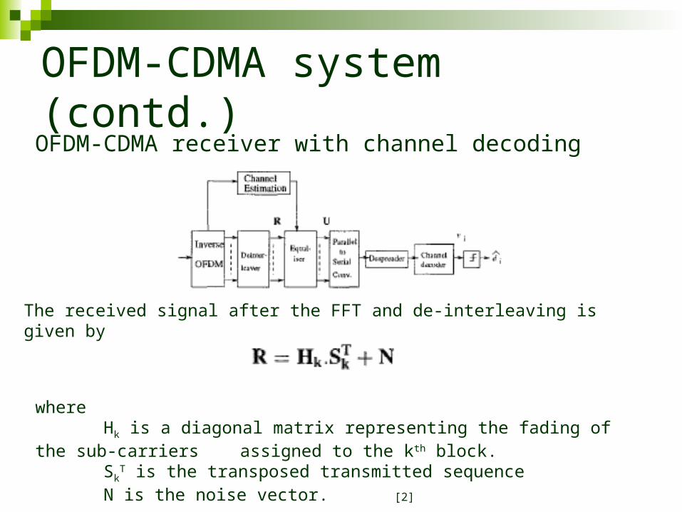
OFDM-CDMA system (contd.)OFDM-CDMA receiver with channel decoding
The received signal after the FFT and de-interleaving is given by
where Hk is a diagonal matrix representing the fading of the sub-carriers assigned to the kth block. Sk
T is the transposed transmitted sequence N is the noise vector. [2]

OFDM-CDMA system (contd.) The received signal is then passed through an equalizer. The output of the equalizer is
given by, U = G.R
where G is a diagonal matrix representing the equalizer coefficients.
The diagonal element hl,l of H is denoted by hl & the diagonal element gl,l of G by gl The equalizer coefficients to perform equal gain combining are given by
U is then despread by the local spreading code Ci to form the soft output vi which is passed to the soft-decision Viterbi decoder.
A sign decision is then made on the output of the Viterbi decoder to form the decoded output data bit di
[2]

Conceptual Implementation We now examine the equations pertaining to OFDM-
CDMA. The transmitted signal of the ith user is written as
wherebn
i (u)(=1 ± j, –1 ± j) is the uth input data at the nth carrier of ith user after S/Pconversion.Cm
i (u) is the mth chip of the spreading code for the ith user.T′s (= PTs) is the symbol duration, andT′c (=T′s /NPG) is the chip duration after S/Pconversion respectively.f0 is the lowest carrier frequency, and Δfsp(=1/Tc′) is the carrier separation.pc = 1(0≤t ≤Tc′), pc = 0 (otherwise).
[1]
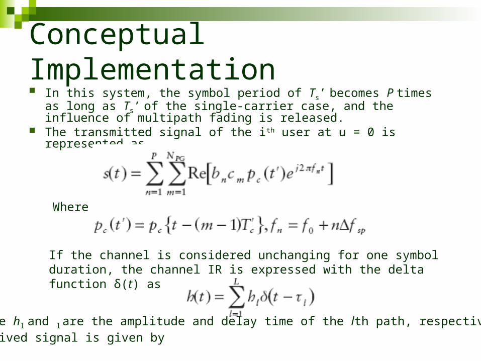
Conceptual Implementation In this system, the symbol period of Ts’ becomes P times as long as
Ts’ of the single-carrier case, and the influence of multipath fading is released.
The transmitted signal of the ith user at u = 0 is represented as
Where
If the channel is considered unchanging for one symbol duration, the channel IR is expressed with the delta function δ(t) as
where hl and l are the amplitude and delay time of the lth path, respectively. Thereceived signal is given by
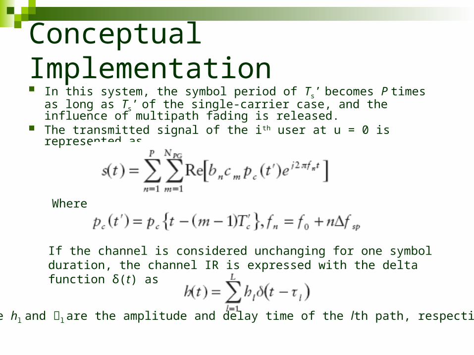
Conceptual Implementation In this system, the symbol period of Ts’ becomes P times as long as
Ts’ of the single-carrier case, and the influence of multipath fading is released.
The transmitted signal of the ith user at u = 0 is represented as
Where
If the channel is considered unchanging for one symbol duration, the channel IR is expressed with the delta function δ(t) as
where hl and ּזl are the amplitude and delay time of the lth path, respectively.
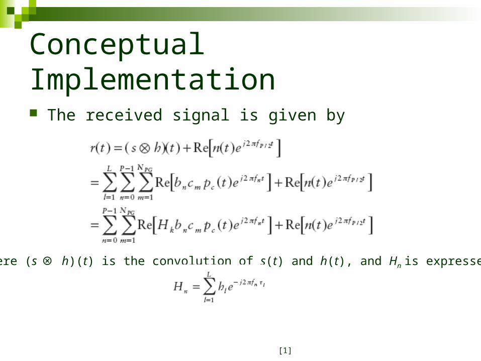
Conceptual Implementation
The received signal is given by
where (s ⊗ h)(t) is the convolution of s(t) and h(t), and Hn is expressed by
[1]
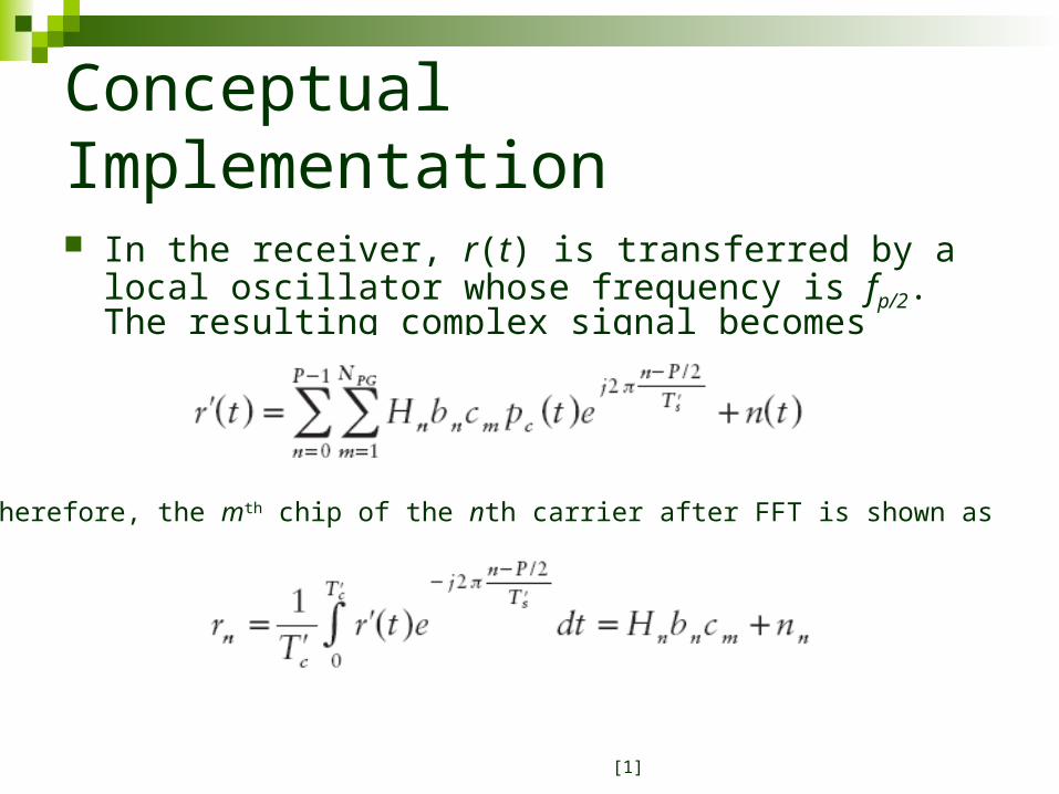
Conceptual Implementation
In the receiver, r(t) is transferred by a local oscillator whose frequency is fp/2. The resulting complex signal becomes
Therefore, the mth chip of the nth carrier after FFT is shown as
[1]
Coding Two new channel coding schemes for OFDM-CDMA are
Orthogonal convolutional coding Super orthogonal convolutional coding.
Orthogonal convolutional coding Consists of two shift registers of length K in which the parallel outputs of
the first shift registers are connected to the second through a connecting block.
The second shift consists of modulo 2 adders and switches. The output of the second shift register is the coder output The switch toggles at 1,2,4 etc. Code Rate R = 1 / 2k
With this coder spreading and coding are combined resulting in bandwidth expansion of 1.
Two different schemes can be adopted – one is different connector assignment for each user, the other is same connector assignment but the coder output is multiplied by separate spreading sequence.
[2]
Coding
Super orthogonal convolutional coding Extension of orthogonal convolutional coder. Code rate R = 1 / 2k-2
Hence larger constraint length is achieved for a given code rate.
Multiple access schemes are obtained in the same way as orthogonal coder.
Convolutional coding and Punctured Convolutional coding are also used in OFDM-CDMA systems.
[2]
PAPR in OFDM-CDMA Systems
All OFDM systems show high PAPR. Many PAPR Reduction techniques available for OFDM Most of these PAPR reduction can be applied to OFDM-
CDMA Added advantage - careful selection of spreading code
and moderate amplifier back-off reduces PAPR further more in OFDM-CDMA
Orthogonal spreading codes can be used for PAPR reduction.
Generate the signals based on several predetermined vectors, and choose the signal with the smallest PAPR
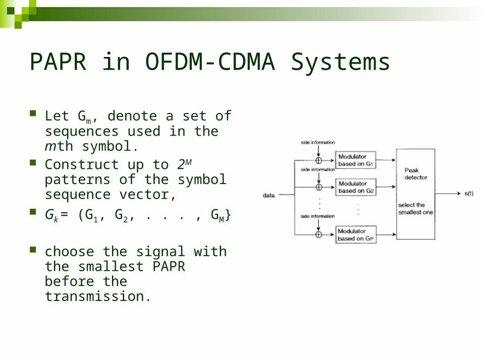
PAPR in OFDM-CDMA Systems
Let Gm, denote a set of sequences used in the mth symbol.
Construct up to 2M patterns of the symbol sequence vector,
Gk = (G1, G2, . . . , GM}
choose the signal with the smallest PAPR before the transmission.
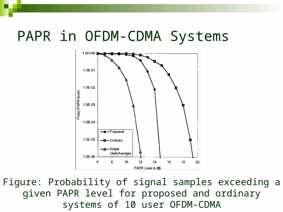
PAPR in OFDM-CDMA Systems
Figure: Probability of signal samples exceeding a given PAPR level for proposed and ordinary systems of 10 user OFDM-CDMA
Multi-antenna OFDM-CDMA
OFDM-CDMA system can be extended to a MIMO and MISO architectures using a space time processing.
Simple STBC based OFDM-CDMA can be very appealing due to high data rate and capacity gain.
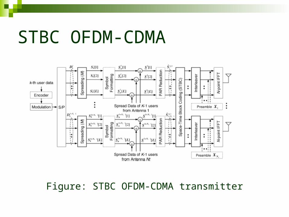
STBC OFDM-CDMA
Figure: STBC OFDM-CDMA transmitter
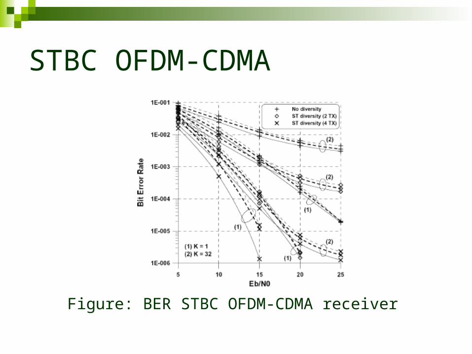
STBC OFDM-CDMA
Figure: BER STBC OFDM-CDMA receiver
Comparison with Other Technologies
To compare the performances of the OFDM-CDMA with MC-CDMA and MC-DS-CDMA systems, assuming:
Equal bandwidth, information rate, and power No narrow-band interference or Doppler spread No additional error-correction coding Perfect channel estimation Maximal-ratio combining Waveform shaping (raised-cosine filter)
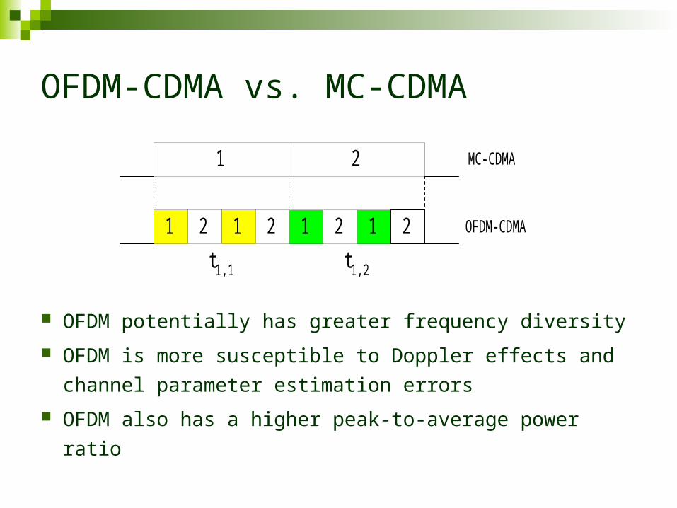
OFDM-CDMA vs. MC-CDMA
OFDM potentially has greater frequency diversity
OFDM is more susceptible to Doppler effects and
channel parameter estimation errors
OFDM also has a higher peak-to-average power ratio
21
1 2 1 2 1 2 1 2
t1,1 t1,2
MC-CDMA
OFDM-CDMA

OFDM-CDMA vs. MC-CDMA
MC-CDMA system:
Order of diversity = R1
Average SNR per channel: OFDM-CDMA system:
Order of diversity = Average SNR per channel:
For a given value of N (Processing gain), the order of diversity for the OFDM-CDMA system is always greater than or equal to the order of diversity for the MC-CDMA system.
2
2
2 cc
EN
22 2
sc
E
M
N
N
RM 22
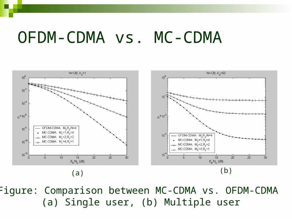
OFDM-CDMA vs. MC-CDMA
Figure: Comparison between MC-CDMA vs. OFDM-CDMA (a) Single user, (b) Multiple user
(a) (b)
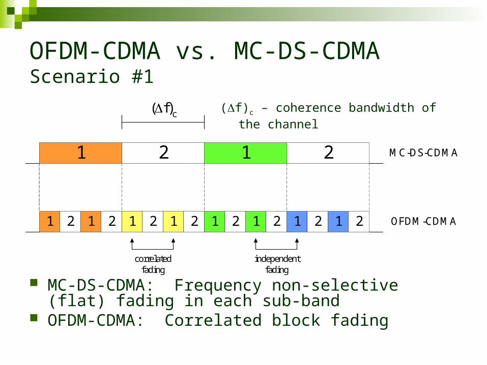
OFDM-CDMA vs. MC-DS-CDMA Scenario #1
MC-DS-CDMA: Frequency non-selective (flat) fading in each sub-band
OFDM-CDMA: Correlated block fading
21
1 2
MC-DS-CDMA
OFDM-CDMA1 1 1 1 1 12 2 2 2 2 2 21
1 2
(f)c
correlatedfading
independentfading
(f)c – coherence bandwidth of the channel

OFDM-CDMA vs. MC-DS-CDMA Scenario #1
MC-DS-CDMA:
OFDM-CDMA (worst-case, perfect correlation):
1 diversity freq. R
11
2
diversity freq.
RMRN
MR
MC-DS-CDMAeCDMAOFDMe PP , ,

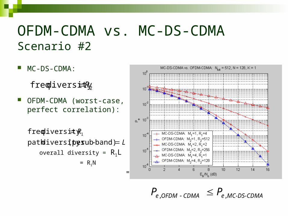
OFDM-CDMA vs. MC-DS-CDMA Scenario #2
MC-DS-CDMA: Frequency selective fading in each sub-band (# of resolvable paths = L = N)
OFDM-CDMA: Frequency non-selective (flat) fading in each sub-band
(f)c – coherence bandwidth of the channel
21
1 2
MC-DS-CDMA
OFDM-CDMA1 1 1 1 1 12 2 2 2 2 2 21
1 2(f)c
OFDM-CDMA vs. MC-DS-CDMA Scenario #2
MC-DS-CDMA:
OFDM-CDMA (worst-case, perfect correlation):
overall diversity = R1L = R1N
= R2
MC-DS-CDMAeCDMAOFDMe PP , ,
2 diversity freq. R
L
R
band)-sub(per diversity path
diversity freq. 1
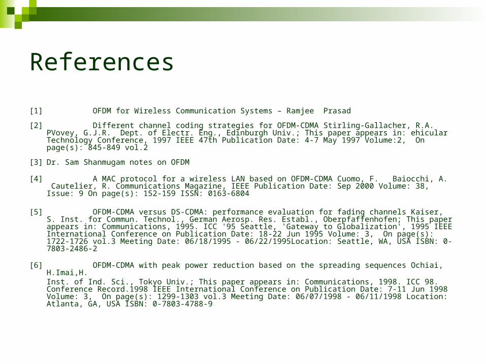
References
[1] OFDM for Wireless Communication Systems – Ramjee Prasad
[2] Different channel coding strategies for OFDM-CDMA Stirling-Gallacher, R.A. PVovey, G.J.R. Dept. of Electr. Eng., Edinburgh Univ.; This paper appears in: ehicular Technology Conference, 1997 IEEE 47th Publication Date: 4-7 May 1997 Volume:2, On page(s): 845-849 vol.2
[3] Dr. Sam Shanmugam notes on OFDM
[4] A MAC protocol for a wireless LAN based on OFDM-CDMA Cuomo, F. Baiocchi, A. Cautelier, R. Communications Magazine, IEEE Publication Date: Sep 2000 Volume: 38, Issue: 9 On page(s): 152-159 ISSN: 0163-6804
[5] OFDM-CDMA versus DS-CDMA: performance evaluation for fading channels Kaiser, S. Inst. for Commun. Technol., German Aerosp. Res. Establ., Oberpfaffenhofen; This paper appears in: Communications, 1995. ICC '95 Seattle, 'Gateway to Globalization', 1995 IEEE International Conference on Publication Date: 18-22 Jun 1995 Volume: 3, On page(s): 1722-1726 vol.3 Meeting Date: 06/18/1995 - 06/22/1995Location: Seattle, WA, USA ISBN: 0-7803-2486-2
[6] OFDM-CDMA with peak power reduction based on the spreading sequences Ochiai, H.Imai,H. Inst. of Ind. Sci., Tokyo Univ.; This paper appears in: Communications, 1998. ICC 98. Conference Record.1998 IEEE International Conference on Publication Date: 7-11 Jun 1998 Volume: 3, On page(s): 1299-1303 vol.3 Meeting Date: 06/07/1998 - 06/11/1998 Location: Atlanta, GA, USA ISBN: 0-7803-4788-9

Questions and Comments