catalogue of products - borimaborima.com/documents/borima_catalogue_products_english.pdf“borima”...
TRANSCRIPT
e-mail:“BORIMA”-EAD; tel. 359//670//6 40 71; fax 359//670//6 29 95; [email protected]
CATALOGUE OF PRODUCTS

“BORIMA”-EAD; tel. 359//670//6 40 71; fax 359//670//6 29 95; [email protected]:
It is a modern technology ,which enables cable connections to function inside thetelecommunication networks by pressing in single - core cables.
The QC ( quick connecting modules ) provide:
Quick connection of copper wires;Solid electric connection;Reliable mechanical contact;Direct work without advance preparation of the wires;Wires with a plastic insulation coating are with diameter from Ø 0.32 to Ø 0.8 mm and diameter of a
insulation coating to Ø 1.47 mm.
QC - MODULES ( QUICK CONNECTING MODULES ) AND ACCESSORIES

“BORIMA” - EAD; tel.359//670//6 40 71; fax 359//670//6 29 95; e-mail: [email protected]
QC - MODULES ( QUICK CONNECTING MODULES ) AND ACCESSORIES
QC DISCONNECTION MODULEModule QC - Disconnection module is used for connecting of cables in Main and Intermediate Distribution frames , Distribution Cabinets and Distribution End Boxes. It can disconnect the circuit and enable themeasurements over the cable network.The module consists of:• Base and Body - made of polycarbonate - incombustible ( fire resistant );• Working lamella - made of phosphoric bronze and galvanized with silver with a thickness of 8 μm;• Pressing lamella - made of phosphoric bronze.
DISCONNECTION MODULE WITH PROTECTION CARTRIDGEIn the base of disconnection module is built-in protection cartridge for arresters of voltage protection. In the cartridge are mounted high voltage arresters, which protected eight and ten telephone pairs.Additional elements:• Contact lamella and grounding comb – made of phosphoric bronze and galvanized with silver with a thickness of 8μm;• Protection cover - made of polycarbonate - incombustible ( fire - resistant )
CONNECTION MODULEModule QC - Connection module is used for connecting of cables in Main and Intermediate Distribution frames , Distribution Cabinets and Distribution End Boxes. It gives a possibility for measuring the cable network.The module consists of:• Base and Body – made of polycarbonate - incombustible ( fire resistant );• Working lamella – made of phosphoric bronze and galvanized with silver with thickness of 8 μm.
QC – GROUNDING MODULEModule QC - grounding is used for derivation of control wires with a perforation plastic insulation to Main or Intermediate Distribution frame, Distribution Cabinet or Terminal Distribution Box.It is the same construction as connection module, but it has only 4 pcs working lamellas.

“BORIMA” - EAD; tel.359//670//6 40 71; fax 359//670//6 29 95; e-mail: [email protected]
QC - MODULES ( QUICK CONNECTING MODULES ) AND ACCESSORIES
PROTECTION CARTRIDGE FOR DISCONNECTION MODULE
Protection cartridge for disconnection module is an independent module, which is mounted on disconnection module and allows multiple mounting and dismounting. It is used for voltage protection for 8 or 10 telephone pairs. In the cartridge are mounted high voltage arresters.It consists of:• Body, cartridge “02” - made of polycarbonate - incombustible• Cover - labeling plate - made of polycarbonate - incombustible, transparent.• Contact lamella, grounding comb - made of phosphoric bronze and galvanized with tin - bismuth ( SuBs ) with thickness 10 μm.
PROTECTION CARTRIDGE FOR CONNECTION MODULE
Protection cartridge for connection module has the same construction and function as the protection cartridge for disconnection module, and the contact lamellas are suitable for mounting on connection module .
PROTECTION CARTRIDGE FOR ONE PAIR
Protection cartridge for one pair is an independent module which is mounted on disconnection module. It used for voltage and current protection for one pair. It allows multiple mounting and dismounting. On one disconnection module can be mounted simultaneously 10 ( 8 ) protection cartridges for one pair.It consists of:• Body - made of polycarbonate – incombustible ( fire resistant );• PCB for voltage and current protection; • Grounding comb - made of phosphoric bronze and galvanized with tin -bismuth (SuBs) with thickness 10 μm.
“BORIMA” - EAD; tel.359//670//6 40 71; fax 359//670//6 29 95; e-mail: [email protected]
QC - MODULES ( QUICK CONNECTING MODULES )AND ACCESSORIES
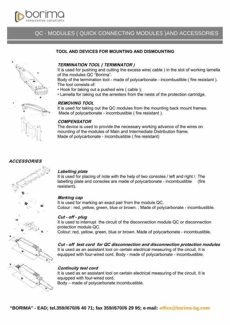
TOOL AND DEVICES FOR MOUNTING AND DISMOUNTING
TERMINATION TOOL ( TERMINATOR )It is used for pushing and cutting the excess wire( cable ) in the slot of working lamella of the modules QC “Borima”. Body of the termination tool - made of polycarbonate - incombustible ( fire resistant ).The tool consists of:• Hook for taking out a pushed wire ( cable );• Lamella for taking out the arresters from the nests of the protection cartridge.
REMOVING TOOLIt is used for taking out the QC modules from the mounting back mount frames.Made of polycarbonate - incombustible ( fire resistant ).
COMPENSATORThe device is used to provide the necessary working advance of the wires on mounting of the modules of Main and Intermediate Distribution frame. Made of polycarbonate - incombustible ( fire resistant)
ACCESSORIES
Labelling plateIt is used for placing of note with the help of two consoles / left and right /. The labelling plate and consoles are made of polycarbonate - incombustible (fire resistant).
Marking capIt is used for marking an exact pair from the module QC.Colour : red, yellow, green, blue or brown. . Made of polycarbonate - incombustible.
Cut - off - plugIt is used to interrupt the circuit of the disconnection module QC or disconnection protection module QC.Colour: red, yellow, green, blue or brown. Made of polycarbonate - incombustible.
Cut - off test cord for QC disconnection and disconnection protection modulesIt is used as an assistant tool on certain electrical measuring of the circuit. It is equipped with four-wired cord. Body - made of polycarbonate - incombustible.
Continuity test cordIt is used as an assistant tool on certain electrical measuring of the circuit. It is equipped with four-wired cord.Body – made of polycarbonate incombustible.
“BORIMA” - EAD; tel.359//670//6 40 71; fax 359//670//6 29 95; e-mail: [email protected]
QC - MODULES ( QUICK CONNECTING MODULES ) AND ACCESSORIES
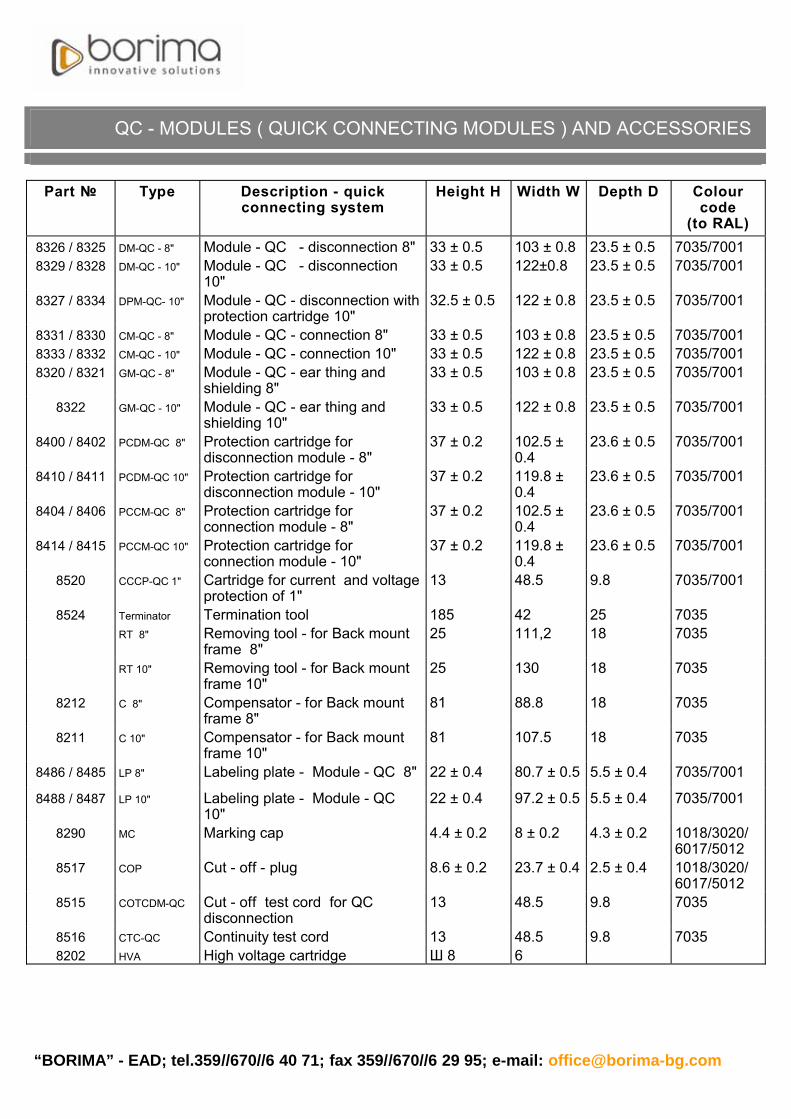
Part Type Description - quick connecting system
Height H Width W Depth D Colour code
(to RAL)8326 / 8325 DM-QC - 8" Module - QC - disconnection 8" 33 ± 0.5 103 ± 0.8 23.5 ± 0.5 7035/70018329 / 8328 DM-QC - 10" Module - QC - disconnection
10"33 ± 0.5 122±0.8 23.5 ± 0.5 7035/7001
8327 / 8334 DPM-QC- 10" Module - QC - disconnection with protection cartridge 10"
32.5 ± 0.5 122 ± 0.8 23.5 ± 0.5 7035/7001
8331 / 8330 CM-QC - 8" Module - QC - connection 8" 33 ± 0.5 103 ± 0.8 23.5 ± 0.5 7035/70018333 / 8332 CM-QC - 10" Module - QC - connection 10" 33 ± 0.5 122 ± 0.8 23.5 ± 0.5 7035/70018320 / 8321 GM-QC - 8" Module - QC - ear thing and
shielding 8"33 ± 0.5 103 ± 0.8 23.5 ± 0.5 7035/7001
8322 GM-QC - 10" Module - QC - ear thing and shielding 10"
33 ± 0.5 122 ± 0.8 23.5 ± 0.5 7035/7001
8400 / 8402 PCDM-QC 8" Protection cartridge for disconnection module - 8"
37 ± 0.2 102.5 ± 0.4
23.6 ± 0.5 7035/7001
8410 / 8411 PCDM-QC 10" Protection cartridge for disconnection module - 10"
37 ± 0.2 119.8 ± 0.4
23.6 ± 0.5 7035/7001
8404 / 8406 PCCM-QC 8" Protection cartridge for connection module - 8"
37 ± 0.2 102.5 ± 0.4
23.6 ± 0.5 7035/7001
8414 / 8415 PCCM-QC 10" Protection cartridge for connection module - 10"
37 ± 0.2 119.8 ± 0.4
23.6 ± 0.5 7035/7001
8520 CCCP-QC 1" Cartridge for current and voltage protection of 1"
13 48.5 9.8 7035/7001
8524 Terminator Termination tool 185 42 25 7035RT 8" Removing tool - for Back mount
frame 8"25 111,2 18 7035
RT 10" Removing tool - for Back mount frame 10"
25 130 18 7035
8212 C 8" Compensator - for Back mount frame 8"
81 88.8 18 7035
8211 C 10" Compensator - for Back mount frame 10"
81 107.5 18 7035
8486 / 8485 LP 8" Labeling plate - Module - QC 8" 22 ± 0.4 80.7 ± 0.5 5.5 ± 0.4 7035/7001
8488 / 8487 LP 10" Labeling plate - Module - QC 10"
22 ± 0.4 97.2 ± 0.5 5.5 ± 0.4 7035/7001
8290 MC Marking cap 4.4 ± 0.2 8 ± 0.2 4.3 ± 0.2 1018/3020/6017/5012
8517 COP Cut - off - plug 8.6 ± 0.2 23.7 ± 0.4 2.5 ± 0.4 1018/3020/6017/5012
8515 COTCDM-QC Cut - off test cord for QC disconnection
13 48.5 9.8 7035
8516 CTC-QC Continuity test cord 13 48.5 9.8 70358202 HVA High voltage cartridge Ø 8 6

“BORIMA” - EAD; tel.359//670//6 40 71; fax 359//670//6 29 95; e-mail: [email protected]
Colour code ( to AL ) Colour7035 light - grey7001 dark - grey3020 red1018 yellow6017 green5012 blue8001 brown
Technical Data
Flammability class VO to UL 94Environment temperature -50°C to +60°CRelative humidity to 80%For modules QCContact resistance in zone of pressing wires < 25 mDrilling voltage between two next lamellas to frequency 50Hz per 1 min
2000 Veff
Using cables for wires with plastic insulation coating with diameter 0.32 mm to 0.8 mm and insulation coating to 1.47 mm
Weight:Module QC - connection, disconnection - 8" 40.4 ± 1 gModule QC - connection, disconnection - 10" 46.5 ± 1 gModule QC - disconnection with protection cartridge -10”( with arresters )
88.0 ± 1 g
Protection cartridge for connection, disconnection module QC for 8” ( with arresters)
67.0 ± 1 g
Protection cartridge for connection, disconnection module QC for 10” ( with arresters)
78.8 ± 1 g
ELECTRICAL PARAMETERS AND GEOMETRIC DIMENSIONS OF USING ARRESTERS
A. Electrical parameters B. Geometric parameter- spark over voltage of the arrester (100 V/s) 230 V ± 20% - body - cylindrical- impulse spark over voltage (1 kV/μs) < 750 V - base diameter - 8 mm- voltage extinction (R = 600 ; RC = 150 /100 nF) > 100 V - height - 6.06 mm ± 0.15 - insulation resistance (100 V=) > 1 G- capacity (for 1 MHz) 5 pF- AC discharge current (10 times; 1 s; 50 Hz) 5 A- discharge current (8/20 �s; 10 times) 5 kA
QC - MODULES ( QUICK CONNECTING MODULES )AND ACCESSORIES

“BORIMA”-EAD; tel. 359//670//6 40 71; fax 359//670//6 29 95; [email protected]:
The Joint closure for telephone networks non pressurized - XAGA 550
XAGA 550
BOKT - 5
XAGA550
is a heat shrinkable closure,used for protection of the cable connections in the telephone networks non pressurized.
It is used for installation of local, underground and pipe cables with a lead or plastic coating.It uses the Raychem - technology of composite materials; the closure guarantees an excellentmechanical stability during and after installation.
The closure includes heat shrinkable sleeve, which isolates, forms and clamps the connection beam andthe metal canister, which forms the internal volume of the closure. Each end of the closure can branch up to3 cables, and a three finger clamp with thermo- melting adhesive is used. The three finger clamp ( clip ) is apart from the branched kit .One branched kit is designed for max. 2 cables branched in the one end only.The heat - shrinkable sleeve is:- CWST - reinforced with integrated metal coating;- WRGT - non-reinforced.
The closures are with capacity to 800’’.1
JOINT CLOSURE FOR TELEPHONE NETWORK NON PRESSURIZEDXAGA 550

“BORIMA” - EAD; tel.359//670//6 40 71; fax 359//670//6 29 95; e-mail: [email protected]
DIMENSIONS
Dimensions in mm
Part Type Number of pairs
Max.dia.over
liner D max
Min.cable dia. d min
Max. jacket opening L
Max. sleeve
length SClamp
CWST Reinforced closure8376 XAGA 550 43/8 150 5 50 43 8 150 350 S8377 XAGA 550 43/8-190 10-70 43 8 180 390 S8378 XAGA 550 43/8-250 10-100 43 8 240 450 S8379 XAGA 550 43/8-370 70-150 43 8 340 570 S8380 XAGA 550 55/12-180 70-200 55 12 180 380 S8381 XAGA 550 55/12-400 70-200 55 12 340 680 S8385 XAGA 550 75/15-260 200-300 75 15 210 450 S8386 XAGA 550 75/15-340 200-300 75 15 340 570 S8387 XAGA 550 75/15-450 200-300 75 15 460 680 S8382 XAGA 550 100/25-590 300-500 100 25 560 900 M8383 XAGA 550 125/30-560 500-800 125 30 560 900 M8384 XAGA 550 164/42-500 1200-1800 164 42 500 920 M
XAGA 550
XAGA 550 kit consists of:Heat-shrinkable sleeve;Metal canister; flexible channels and under clip;Aluminum foils;Emery tissue;Silica gel;Aluminum cable foils;Installation procedure;Shield continuity wire assembly.
BOKT KIT -5 consists of:Three finger clamp (clip) with thermo-melt adhesive;Shield continuity wire assembly;Aluminum foils.
Description BOKT -5- BOKT -5 S-branched kit with small clamp;- BOKT -5 M-branched kit with middle clamp;- BOKT -5 L-branched kit with large clamp.

e-mail:“BORIMA”-EAD; tel. 359//670//6 40 71; fax 359//670//6 29 95; [email protected]
The back mount frames are an universal equipment, used for attaching and mounting of modules QC.
The back mount frames are designed for the following modules:Modules QC, produced by “BORIMA” -EAD.;Modules “KRONE” - series LSA+.
The capacity of the back mount frame: from 10” to 500” for 10” module; from 8” to 400” for 8” module.Material: chrome nickel steel.
Hardness, HB 30 192Electrical conductivity , s 0.85Heat conductivity, W / ( mK ) 14Magnetic conductivity, Wb /A 1.010
••
Physical and mechanical characteristics of the material
BACK MOUNT FRAMES FOR MOUNTING OF MODULES - QC

“BORIMA” - EAD; tel.359//670//6 40 71; fax 359//670//6 29 95; e-mail: [email protected]
BACK MOUNT FRAMES FOR MOUNTING OF MODULES - QC
DIMENSIONS Dimensions in mm
Modules QC “BORIMA”8" Modules QC”BORIMA” 10" KRONE 10" LSA +t W V T n t W V T n t W V T n
25 85 19.5 22 25 104 19.5 22 25 104 20.5 22
25 85 19.5 35 50 25 104 19.5 35 50 25 104 20.5 35 50
Part Type Description
8114 - 8127 T 22 - 8" Back mount frame for mounting of 8” module T 22
8004 - 8032 T 35 - 8" Back mount frame for mounting of 8” module T 35
8128 - 8164 T 22 - 10" Back mount frame for mounting of 10” module T 22
8045 - 8110 T 35 - 10" Back mount frame for mounting of 10” module T 35
According customer request T 22 - LSA Back mount frame for mounting of
10”LSA module T 22 According customer
request T 35 - LSABack mount frame for mounting of 10”LSA module T 35

“BORIMA”- EAD; tel. 359//670//6 40 71; fax 359//670//6 29 95; [email protected]:
The Multi - pair splicing connector MARK III
MARK III .MARK III
is used for connecting pair cables in the telecommunicationnetwork by pressing of conductors with copper wires.The connectors provide:
quick connection of copper wires ;solid electrical contact;reliable mechanical contact;direct work without advance preparation of the wires;different kinds of connections with a diameter of the wires from Ø 0.32 mm to Ø 0.8 mm and a plastic insulation
coating;Construction:
the body, consists of two plastic halves with built in working and cutting lamellas - made of shock - resistantpolycarbonate ;
cover ( upper and lower ) - made of shock - resistant polycarbonate .The built in working cutting lamellas are made of phosphoric bronze and a galvanized coating with tin - bismuth( SuBs ).
:10 pair - it is designed to connect 10 pairs of multi - pair cable with copper wires:25 pairs - it is designed to connect 25 pairs of multi - pair cable with copper wires.
:We offer you a kit of tools, production of AMP. to work with multi - pair splicing connector.
•••••
•
•
Production:
Tools
MULTI - PAIR SPLICING CONNECTOR MARK III

“BORIMA” - EAD; tel.359//670//6 40 71; fax 359//670//6 29 95; e-mail: [email protected]
MARK III
TECHNICAL DATA
Product MARK III - 10" MARK III - 25"Length D, mm 71.4 164Width W, mm 15.8 14.4Height H, mm 10.4 9.6Weight, g 9.68 15
MATERIAL AND COLOUR OF THE PRODUCT
Product MARK III - 10" MARK III - 25"
Material Colour Material ColourBase(1) polycarbonate
and/ PBTorange, RAL 1028
polycarbonate and/ PBT
orange, RAL 1028
Cover (2) polycarbonate and/ PBT
reseda, RAL 1032
polycarbonate and/ PBT
reseda, RAL 1032
Cover (3) polycarbonate and/ PBT
reseda, RAL 1032
polycarbonate and/ PBT
transparent
Part Type Description
8300 MARK III - 10" - jelli filled
Multi-pair connector for 10” – jelly filled half-tap
8301 MARK III - 10" - jelli filled
Multi-pair connector for 10” – jelly filled splicing
8302 MARK III - 10" - dry Multi-pair connector for10” – dry half-tap
8303 MARK III - 10" - dry Multi-pair connector for 10” – dry splicing
8305 MARK III - 25" - jelli filled
Multi-pair connector for 25” – jelly filled splicing
8306 MARK III - 25" - jelli filled
Multi-pair connector for 25” – jelly filled half-tap
8307 MARK III - 25" - dry Multi-pair connector for 25” – dry half-tap
8308 MARK III - 25" - dry Multi-pair connector for 25” – dry splicing

e-mail:“BORIMA”EAD; tel. 359//670//6 40 71; fax 359//670//6 29 95; [email protected]
The connectors are designed to enable the cable connections to function in telecommunicationnetwork by pressing of conductors with copper wires.The connectors provide:
quick connection of single copper wires;an auspicious mechanical contact;an auspicious electrical contact;no necessity of advance preparation of the wires;different kinds of connections with a diameter of the wires from 0.32 mm to 0.8 mm and a plastic
insulation coating;Construction:
Body and cover -made of incombustible polycarbonate ( fire - resistant );Contact lamella - made of phosphoric bronze and a galvanized tin-bismuth ( SuBs ) or tin-lead ( SuPv )
coating - 10 m;The internal space of the connectors ( chamber ) is filled with hydrophobic filler, which guarantees
protection of the contact from humidity and chemical exposures.
The pressing of the wires is made by special tongs.
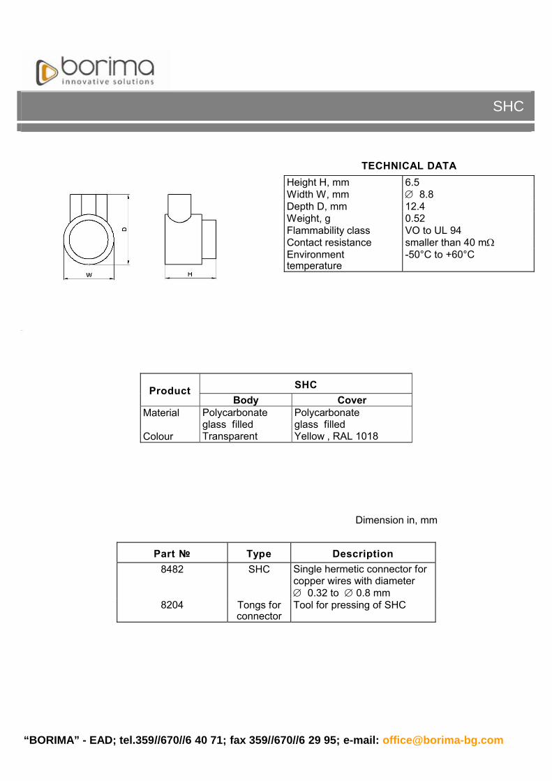
SHC
•••••
••
μ•
SINGLE HERMETIC CONNECTORS - SHC
“BORIMA” - EAD; tel.359//670//6 40 71; fax 359//670//6 29 95; e-mail: [email protected]
Dimension in, mm
SHC
TECHNICAL DATAHeight H, mm 6.5Width W, mm 8.8Depth D, mm 12.4Weight, g 0.52Flammability class VO to UL 94Contact resistance smaller than 40 mEnvironmenttemperature
-50°C to +60°C
SHCProductBody Cover
Material Polycarbonateglass filled
Polycarbonateglass filled
Colour Transparent Yellow , RAL 1018
Part Type Description8482 SHC Single hermetic connector for
copper wires with diameter 0.32 to 0.8 mm
8204 Tongs for connector
Tool for pressing of SHC

e-mail:“BORIMA”- EAD; tel. 359//670//6 40 71; fax 359//670//6 29 95; [email protected]
The main and the intermediate distribution frame ( MDF ),
The main and the intermediate distribution frame ( MDF )
Bilateral distribution frame “Borima”
Wall two - facade distribution frame “Borima”
Wall one - facade distribution frame “Borima”
Reconstruction of old type of distribution frame
is designed to connect thesubscriber lines connection lines of the cable telecommunication network and thestation equipment. Inside the distributor can be; arranged the connections, interruptedthe line; measured the stationary and linear part of the network; current and voltageprotected the station equipment and other necessary technical actions. It is designed touse modules QC.
has a cylindrical modularconstruction, which allows accomplishment of different kinds of combinations in heightand length.
Construction:base - supports the construction and is used for attaching to the floor. It includes a back
mount frame for a cable beam.It is made of sheet steel and coated with polyester against corrosion;
working part - includes a vertical support column, horizontal support elements, metaldetails , which form arranged construction, coated with polyester against corrosion,plastic support for back mount frames, made of chrome - nickel sheet - metal, which aredesigned to mount modules QC;upper part - is used for mounting the construction to the ceiling, it includes a cable
beam crib. It is made of steel coated with polyester against corrosion.
- If the designer decides and if there is enoughspace, the construction can be used as a main distributor of a bigger exchange (it isrecommended for more than 4000 telephone posts ).It is possible to work ( mounting andserves ) on the both sides. The location of the back mount frames is: on the face side -horizonta l, and on back side - vertical.
- It is mounted on the wall. Theposition of the back mount frames is : horizontal back mount frames for subscriber side -in the upper part of the construction; vertical back mount frame for network side - in thelower part of the construction.
- It is mounted on a wall. The positionof the back mount frames is: vertical back mount frames for subscriber and linear part ofthe telecommunication network.
- It is used to restore an existingbilateral construction with modules QC. It is done by a console for reconstruction ofMDF - a vertical part and a support element for reconstruction of a horizontal part.
•
•
•
Types:
MAIN AND INTERMEDIATE DISTRIBUTION FRAME ( )MDF

“BORIMA” - EAD; tel.359//670//6 40 71; fax 359//670//6 29 95; e-mail: [email protected]
MAIN AND INTERMEDIATE DISTRIBUTION FRAME (REPARTITOR)
TECHNICAL DATAHorizontal step Tw, mm 250Vertical step Tn, mm 250Depth D, mm - bilateral distribution frame
850
Depth D, mm - wall distribution frame
700
Colour Light - grey, to RAL7035Relative humidity, % 80Environment temperature to 50°C
Type MDF DescriptionTFDF “Borima”
Two facade distribution frame for modules - QC
WTFDF “Borima”
Wall two - facade distribution frame for modules - QC
WOFDF “Borima”
Wall one - facade distribution frame for modules - QC
RC-V Reconstruction Console of MDF - vertical part
RSE-H Reconstruction Support element of MDF - horizontal part
BMFH-H Back mount frames holder -horizontal part
BMFH-V Back mount frames holder -vertical part
CFR Cartridge for rosette of MDF

“BORIMA”-EAD.; tel. 359//670//6 40 71; fax 359//670//6 29 95; [email protected]:
The Cross connection cabinet CCC 300” - 00 “ P28 is an equipment,which connects the main and the distributing cables in thetelecommunication network. The cabinet gives the possibility to arrangethe connections, to interrupt the line and to measure the telecommunicationcable network.
The cabinet is adapted to outdoor use on a concrete fundament.
The body of the cabinet is made of glass filled polycarbonate, that isincombustible , UV protected, shock-proof, and high weather - resistant.
The base and the roof are made of incombustible polycarbonate.Hermetically the cabinet is isolated by PVC sealing profile, that keeps theworking parameters in a wide temperature scope/According to DIN 7863 /.Hermetically the openings of the incoming and theoutgoing cables are isolated by waterproof compounds and fillers . Thecabinet is equipped with back mount frames ( channels ) for modules QC “Borima”.
The EQUIPMENT consists of :modules QC - disconnecting, connecting and grounding modules;main frame / contour / - made of zinc galvanized steel and subsequently
coated with polyester paint.channels for installing modules QC “ Borima “ 4 pcs.; the length is
according to the capacity of the cables;4 entrances between the base and the body, that secure watertight
passage of all the cables / incoming and outgoing /;arranged rings;cable holders / incoming and outgoing / in the base and the body of the
cabinet;fundament bolts for easy installation and levelling ;4 pieces of grounding bolts ;a set of lock.A System for controlling and protecting the cabinet is made according to
an order.
••
•
•
••
•••
CROSS CONNECTION CABINET CCC 300” - 00” P28

“BORIMA” - EAD; tel.359//670//6 40 71; fax 359//670//6 29 95; e-mail: [email protected]
Type H W DCCC 300”P 955 700 335CCC 400"P 955 700 335CCC 600"P 1120 700 335CCC 800"P 1260 700 335CCC 900"P 1260 700 335CCC 1200"P 1460 700 335
CROSS CONNECTION CABINET CCC 300” – 1200”P
MATERIAL AND COLOUR OF THE PRODUCT
Base elements Material ColourBody polycarbonate glass - filled light - grey similar to RAL 7035
Base polycarbonate glass - filledmetal with organic coating
light - grey similar to RAL 7035black similar to RAL 9005
Roof polycarbonate glass - filledmetal with organic coating
light - grey similar to RAL 7035black similar to RAL 9005
Inputs and outputs of the back mount frames
4 pcs 90 mm each
Flammability class VO to UL 94Relative humidity to 100%Environment temperature
-40°C to +70°C
Part Type Description Equipment with modules QC
8500 CCC 300"PCross connection cabinet with 4 back mount frames by 9 modules - QC each
connection module - 16pcsdisconnection module - 16pcs grounding module - 4pcs
8501 CCC 400"PCross connection cabinet with 4 back mount frames by 11 modules - QC each
connection module - 20pcsdisconnection module - 20pcs grounding module - 4pcs
8502 CCC 600"PCross connection cabinet with 4 back mount frames by 16 modules - QC each
connection module - 30pcsdisconnection module - 30pcs grounding module - 4pcs
8503 CCC 800"PCross connection cabinet with 4 back mount frames by 21 modules - QC each
connection module - 40pcsdisconnection module - 40pcs grounding module - 4pcs
8504 CCC 900"PCross connection cabinet with 4 back mount framesby24 modules - QC each
connection module - 46 pcsdisconnection module - 46 pcsgrounding module - 4pcs
8505 CCC 1200"PCross connection cabinet with 4 back mount frames by 31 modules - QC each
connection module - 60pcsdisconnection module - 60pcsgrounding module - 4pcs

“BORIMA” - EAD; tel.: 359//670//6 40 71; fax: 359//670//6 29 95; e-mail: [email protected]
CROSS CONNECTION CABINET CCC 1400” – 2800”P
TECHNICAL DATA Dimension in mm
Type H W DCCC 1400” P 1260 1440 335CCC 1600” P 1260 1440 335CCC 1800” P 1260 1440 335CCC 2400" P 1460 1440 335CCC 2800" P 1460 1440 335
Inputs and outputs of the back mount frames
8 pcs 90 mm each
Flammability class V0 to UL94Relative humidity to 100%Environment temperature
-40°C to +70°C
MATERIAL AND COLOUR OF THE PRODUCTBase elements Material Colour
Body polycarbonate glass - filled light - grey similar to RAL 7035Base polycarbonate glass - filled light - grey similar to RAL 7035Roof polycarbonate glass - filled
metal with organic coatinglight - grey similar to RAL 7035light - grey similar to RAL 7035
Part No Type Description Equipment with modules QC
8506 CCC 1400” PCross connection cabinet with 8 back mount frames by 19 modules - QC each
connection module - 72 pcsdisconnection module-72 pcsgrounding module - 8pcs
8507 CCC 1600” PCross connection cabinet with 8 back mount frames by 21 modules - QC each
connection module - 80 pcsdisconnection module-80 pcsgrounding module - 8pcs
8508 CCC 1800” PCross connection cabinet with 8 back mount frames by 24 modules - QC each
connection module - 92 pcsdisconnection module-92 pcsgrounding module - 8pcs
8509 CCC 2400" PCross connection cabinet with 8 back mount frames by 31 modules - QC each
connection module - 120pcsdisconnection module - 120pcsgrounding module - 8pcs
8510 CCC 2800” PCross connection cabinet with 8 back mount frames by 36 modules - QC each
connection module - 140pcsdisconnection module - 140pcsgrounding module - 8pcs

“ BORIMA”- EAD; tel.359//670//6 40 71; fax 359//670//6 29 95; e-mail: [email protected]
The Terminal Distribution Box 8"- 10"M is used to connectterminal devices by the distributing telecommunication networkwith the exchange. It is designed to be used for outdoor (facades of buildings or poles ) and indoor mounting . The body (body and cover ) is made of incombustible polycarbonate .The box is equipped with a back mount frame ( channel ) to 2modules QC "Borima".
Each box TB 8" - 10"M is equipped with:modules QC;back mount frames ( channels ) for modules QC;grounding bridge with a clip and a cable shoe;rubber sealing with an input and output openings - 3 pcs;hermetic rubber sealing between the body and the cover;clamp for supporting the incoming cable - 2 pcs;a kit of screws, washers and pins for outdoor and indoor
mounting;a special bolt for closing the box.
•••••••
•
TERMINAL DISTRIBUTION BOX 8” - 10” M

“BORIMA” - EAD; tel.: 359//670//6 40 71; fax: 359//670//6 29 95; e-mail: [email protected]
TECHNICAL DATAHeight H, mm 173Width W, mm 131Depth D, mm 76Weight – 8”M; 10”M, kg 0.450; 0.470Inputs / Outputs:
3 rubber seal with possibility for:-2pcs input opening for 10” cable; -15 pcs output openings for one pair cable;- grounding cable
Material of the box polycarbonate glass - filledMaterial of the module polycarbonate glass - filledColour light - grey, RAL 7035Flammability class VO to UL 94Relative humidity to 100%Environmenttemperature
- 45 to +75 C
TDB 8” – 10” M
Part No Type Description Equipment
8265 TDB 8"M
Terminal distribution box for 8” with backmount frame for 2 modules
connection, disconnection - 1pcGrounding module - 1pc
8266 TDB 10"MTerminal distribution box for 10” with backmount frame for 2 modules
connection, disconnection - 1pc Grounding module - 1pc

; tel.359//670//6 40 71; fax 359//670//6 29 95; e-mail:“ BORIMA”- EAD [email protected]
The Terminal Distribution Box 30”- 50” M distributescables of the secondary cable network and subscriber cablesof the tertiary cable network. It is designed to be used formechanical and electrical indoor and outdoor installation(outer walls of buildings and poles).The body (body and cover) is made of incombustiblepolycarbonate .The box can be eqipped with a back mount frame up to 6modules QC (Quick Connecting System) “Borima”.
Each box DB 30”- 50” M is equipped with:modules- QC (disconnecting or connecting);back mount frame for mounting of modules QC;grounding bridge with a clip and a cable shoe;rubber sealing with 1 inlet and 1 outlet, according to the
capacity;cover sealing, made of an air-foamed rubber;supporting bracket of the incoming cable 1 pc;a kit of screws, washers and pins for outdoor and indoor
mounting;brackets- 2pcs for mounting on the pole
TERMINAL DISTRIBUTION BOX 30” - 50” M

“BORIMA” - EAD; tel.: 359//670//6 40 71; fax: 359//670//6 29 95; e-mail: [email protected]
TECHNICAL DATAHeight H, mm 325Height H1, mm 350Width W, mm 190Depth D, mm 85Weight 30”M; 50”M, kg 0.912 kg. ÷ 1.082 kg.Material of the box polycarbonate glass-filled Material of the modules polycarbonate glass-filledColour light grey, RAL 7035 Flammability class VO to UL 94Relative humidity to 100%Environment temperature - 45 to +75 C
NOTE: H – Height of the box without brackets (for mounting on the wall); H1 – Height of the box with brackets (for mounting on the pole).
TDB 30” – 50” M
Part No Description Specification Equipment with modules QC
8275
8277
TDB 30” M
TDB 50” M
Terminal Distribution Box with capacity from 30” up to 50” and back mount frame for modules
Connection, disconnection –according the capacity
Grounding module – 1pc.

“ BORIMA”- EAD; tel.359//670//6 40 71; fax 359//670//6 29 95; e-mail: [email protected]
The Terminal Distribution Box 70” 100” M distributes thecables of the secondary cable network and the subscribercables of the tertiary cable network. It is designed to be used formechanical and electrical indoor and outdoor installation.The body (body and cover) is made of incombustiblepolycarbonate.The box can be equippted with a back mount frame up to 11modules QC (Quick Connecting System) “Borima”Each box TB 70” 100” M is equipped with:
modules QC (disconnecting or connecting);back mount frame for mounting of modules QC;grounding bridge with a clip and a cable shoe;rubber sealing with 1 inlet and 2 outlets, according to the
capacity;cover sealing, made of air-foamed rubber;supporting bracket of the incoming cable 1 piece;a kit of screws, washers and pins for outdoor and indoor
mounting;a special bolt for shutting the box
TERMINAL DISTRIBUTION BOX 0” - 0” M7 10

“BORIMA” - EAD; tel.: 359//670//6 40 71; fax: 359//670//6 29 95; e-mail: [email protected]
TECHNICAL DATAHeight H, mm 410Height H1, mm 430Width W, mm 210Depth D, mm 100Weight 70”M; 100”M, kg 0.426 kg. ÷ 1.656 kg.Material of the box polycarbonate glass-filled Material of the modules polycarbonate glass-filledColour light grey, RAL 7035 Flammability class VO to UL 94Relative humidity to 100%Environment temperature - 45 to +75 C
NOTE: H – Height of the box without brackets (for mounting on the wall); H1 – Height of the box with brackets (for mounting on the pole).
TDB 70” – 100” M
Part No Description Specification Equipment with modules QC
8278
8282
TDB 70” M
TDB 100” M
Terminal Distribution Box with capacity from 70” up to 100” and back mount frame
for modules
Connection, disconnection –according the capacity
Grounding module – 1pc.

“BORIMA”- EAD; tel. 359//670//6 40 71; fax 359//670//6 29 95; [email protected]:
The Plastic chute of telecommunications cables is designed to be used for underground cable lines. Insidethe chute can be mounted mechanical, heat shrinkable or optical closures. It is used for storing of cablereserve too. They are suitable for mounting around an existing cable because of the need of a future repairor insurance of diversion without cutting the cable.
Construction:
Upper and lower shell with four entrances. There is a rubber sealing fixed on the lengthwise of the lowershell.
Universal adapters - 2 pcs. specially designed for mounting of HDPE pipe with a diameter of 32 mm and40 mm for optical cables;Closing entrance - 2 pcs. Conical deaf entrances are used for sealing of the unused entrances;Metal supporting frame
The Shells are mounted with stainless screwed connections.
PLASTIC TELECOMMUNICATION CABLE CHUTE

“BORIMA” - EAD; tel.: 359//670//6 40 71; fax: 359//670//6 29 95; e-mail: [email protected]
Part NoMaterial – upper and lower shellColour
They are made of polypropylene with 30% glassYellow, RAL 1018
Universal adapters PolypropyleneBolt connections Stainless steel
8443 Support frameColour
Steel with powder coatingGrey RAL 7035
Technical dataMechanical stability- Loading (5 min)- Hit (10 times)
- Hit (1 time)
-16 kN over the whole surface of the chute- 6 kg guillotine, falling from 90 cm. height to the center of the chute- 7 kg device with point hit, falling from 80 cm height, depth entering 20mm to the center of the chute
Tightness with universal adapters Average tightnessWeight Round 27 kg.
A complete set of a chuteNo Description Piece per set1 Upper shell 12 Lower shell 13 Metal support frame 1 according to the customer
request4 Universal adapters - set
- set of rubber seals- rubber entrance 32 and 40
2
5 Plug-up entrance 32 and 40 26 Protection gel 17 Cleaning tissue 28 Protective covers 1 kit9 Screwed connections 1 kit10 Seal rubber for replacement - 4 m and adhesive according to the customer
request
PLASTIC TELECOMMUNICATION CABLE CHUTE

“BORIMA”-EAD; tel. 359//670//6 40 71; fax 359//670//6 29 95; [email protected]:
Mechanical and fiber optic closures, serve for protection of connections in non-pressurized networks. Fitsdifferent types of cables:
Telecommunications- Plastic coated copper cables;- Fiber optic cables / for closure type MAM /.
Electric/power cables- Up to 1000 Volt
Benefits:Quick and easy installation;No special tools needed;For multiple use;For aerial and underground installations.
One closure kit consists of two symmetrical half-shells with a foamed rubber length seal fixed in the top shell/ excluding FDM1 and FDM2, where the design is type “Jar”/. Entry seals keep the closure absolutewatertight. The shells are screwed together with nuts and bolts, made of stainless steel.
MECHANICAL AND FIBER-OPTIC CLOSURES

“BORIMA” - EAD; tel.: 359//670//6 40 71; fax: 359//670//6 29 95; e-mail: [email protected]
One closure kit consists of:
Two symmetrical half-shells, made of material polypropylene - colour yellow (RAL1023);Foamed rubber length seal of the shell;Rubber seals between the two halves at closure installation;Bolt splices for mechanical connection of the shells;Cable holders
Types:In-Line mechanical closure MVM 23 / 200 - suitable for 2 pcs. of cable with diameter up
to 23 mm;
MECHANICAL IN – LINE CLOSURE FOR CONVENTIONAL COPPER CABLES TYPE MVM
Part No Type of the closure
Max. numberpair
Outer diameter of the cable
Splice opening length (mm)
Dimension of the closure
D x W x H
8360 MVM23/ 200 30 2 8 23 200 470 133 90

“BORIMA” - EAD; tel.: 359//670//6 40 71; fax: 359//670//6 29 95; e-mail: [email protected]
One closure kit is the same as the In-Line closure type MVMType MAM is with two entrances and with two outlets.Types:
Mechanical Branch-off closure type MAM 23 / 200 - suitable for 4 pcs of cable with diameter up to 23 mm
MECHANICAL BRANCH-OFF CLOSURE TYPE MAM FOR CONVENTIONAL COPPER CABLES AND OPTICAL FIBERS
Part No Type of the closure
Max. numberpair
Outer diameter of the cable
Splice opening length (mm)
Dimension of the closureD x W x H
8358 23/ 200 50 4 8 23 200 470 223 104

“BORIMA” - EAD; tel.: 359//670//6 40 71; fax: 359//670//6 29 95; e-mail: [email protected]
The closures type FDM are type “Jar” for making of In-Line and Branch-off connections
One closure kit consists of:Body - made of material polypropyleneCover - made of material polypropylene - black ( RAL 8022 );Rubber seal;Former (schablone) and keys (for FDM 2).
Types:Mechanical closure FDM 1 - suitable for 4 pcs of cable from 6 to 14 mmMechanical closure FDM 2 - suitable for 4 pcs of cable from 6 to 25 mm
Part No Type of the closure
Max. numberpair
Outer diameter of the cable (mm)
Splice opening length (mm)
Dimension of the closure
( x L)8362 FDM 1 30 4 x 6 - 14 230 75 x 170
8363 FDM 2 70 4 x 6 - 23 120 100 x 280
MECHANICAL CLOSURE TYPE FDM

“BORIMA” - EAD; tel.: 359//670//6 40 71; fax: 359//670//6 29 95; e-mail: [email protected]
The fiber optic closure is designed to connect optical cables with metal elements or dielectric in the following cases:
In–Line and In–Line–Branch–off closure - 1 : 1; 1 : 2; 1 : 3 at maximum 8 pcs of cassettes for organization of the welding;
End closure - 1 : 1 to 1 : 2;Branched-Transit closure - 1 : 1; 1 : 2 (without cutting-off the base cable).
The closure is designed for optical cables with outer diameters from 6 to 23 mm.
Installation:
At environment temperature -from - 5 C to +50 C and relative humidity to 98 % without condense humidity.
FIBER – OPTIC CLOSURE– 23 / 200 F
Part Nowith / without
heat shrinkable splice
protection
Type of the closure
Fiber opticsplice
cassette
Outer diameter of the cable
Splice opening length (mm)
Dimension of the closure
D x W x H
8353 / 8353 23/ 200 FO -12 fibers 2 4 8 23 200 470 223 104
8354 / 8354 23/ 200 FO -24 fibers 3 4 8 23 200 470 223 104
8355 / 8355 23/ 200 FO -48 fibers 5 4 8 23 200 470 223 104
8356 / 8356 23/ 200 FO -72 fibers 7 4 8 23 200 470 223 104

“BORIMA”-EAD; tel. 359//670//6 40 71; fax 359//670//6 29 95; [email protected]:
Distribution Metal Niche (Type Cabinet)The Distribution Metal Niche is designed to be used for indoor telephone installations, located inbuildings and it connects the incoming cable from the cable network with terminal devices.
The Distribution Metal Niche is made of metal sheets with thickness 1.5 mm;The Coating is powder painted with colour RAL 7035 or according to the request of the customer;Types:
with one doorwith two doors
They are equipped with safety locks with one and the same combination
- ;- ;
.
METAL NICHE TYPE CABINET

“BORIMA” - EAD; tel.: 359//670//6 40 71; fax: 359//670//6 29 95; e-mail: [email protected]
TECHNICAL DATA
Part No H, mm W, mm D, mm8390 350 350 100 8391 400 400 100 8392 500 500 100 8393 600 700 200 8394 800 700 200
• According to an order they can be produced with dimensions specified by the customer.• The Equipment – chrome-nickel back mount frames for modules type “Borima” or according to the
order of the customer.
METAL NICHE – TYPE CABINET
“BORIMA”-EAD; Tel.: 359//670//6 40 71; Fax: 359//670//6 29 95; e-mail: [email protected]
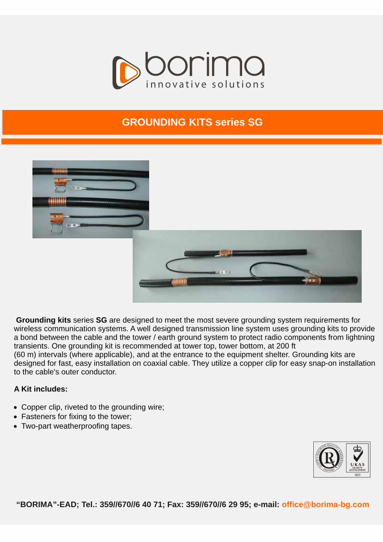
GROUNDING KITS series SG
.
Grounding kits SG
A Kit includes:
series are designed to meet the most severe grounding system requirements forwireless communication systems. A well designed transmission line system uses grounding kits to providea bond between the cable and the tower / earth ground system to protect radio components from lightningtransients. One grounding kit is recommended at tower top, tower bottom, at 200 ft(60 m) intervals (where applicable), and at the entrance to the equipment shelter. Grounding kits aredesigned for fast, easy installation on coaxial cable. They utilize a copper clip for easy snap-on installationto the cable's outer conductor.
Copper clip, riveted to the grounding wire;Fasteners for fixing to the tower;Two-part weatherproofing tapes
•••

“BORIMA” - EAD; tel.: 359//670//6 40 71; fax: 359//670//6 29 95; e-mail: [email protected]
* GROUNDING KIT series SG is supplied with weatherproofing material which must be installed properly to insure optimum performance in these conditions.
GROUNDING KITS series SG
Characteristics
Material
Clip Copper
Bail Stainless Steel
Rivets Copper
Cable shoes Tin Plated Copper
Bonding Conductor 7-Strand Copper Wire Cross-Sectional Area 16 2
Mechanical Part No
According customer request
SG 1/2" 15.37 mm to 16.83 mm
According customer request
SG 7/8" 26.7 mm to 28.7 mm
According customer request
SG 1 1/4" 38.4 mm to 40.1 mm
Fits cable diameters
8549 SG 1 5/8" 49.0 mm to 50.8 mmCable shoes clearance holes 3/8 – 16 or 10 screws
Bail closure force Maximum of 11 kg.
Environmental
Operating Temperature -45° to +85°Ñ
Storage Temperature -45° to +85°Ñ
Weather Resistant * Salt Spray, Rain, Ice, Wind, UV

.“BORIMA” - EAD; Tel : 359//670//6 40 71; Fax: 359//670//6 29 95; e-mail: [email protected]
FIXING CABLE CLAMPS
The fixing cable clamps
They give possibility for installation at:
are used for fixing and strengthening of cables and tubes with differentfunction.They are made of corrosion-proof metal elements and calibrated shells from polyamide, UVresistant.The protection of the cable or the tube against possible damage is ensured with the help of the strongpolyamide shells, combined with tightening bolt.An additional reliable catch achieved, using self-locking nut.
lat profiles with thickness maximum to 10 mm ( ig.1);ubes with diameter maximum to 18 mm ( ig.2);etal ropes with diameter maximum to 18 mm ( ig.3).
and ageing
ing
F FT FM F
•••

“BORIMA” - EAD; tel.: 359//670//6 40 71; fax: 359//670//6 29 95; e-mail: [email protected]
Fig.1 Fig.2 Fig.3
Types: The types are according to the dimensions of the outer diameter of the cable or the tube, which they fix.
The types are according to the number of cables or the number of tubes, which they fix.
FIXING CABLE CLAMPS
Material
Metal part of the clamp Stainless steel
Shells Polyamide, black
Connecting elements Stainless steel
Part NoSingle Double Triple
Fixing cable clamp 1 ” According customer request 8450 8548
Fixing cable clamp 1 ¼” According customer request 8493 8547
Fixing cable clamp “ According customer request 8452 8546
Fixing cable clamp ½” According customer request 8451 8545
Fixing cable clamp R 8 According customer request 8453 -
Single With two polyamide shells
Double With four polyamide shells
Triple With six polyamide shells
; : :“BORIMA” - EAD Tel. 359//670//6 40 71; Fax 359//670//6 29 95; e-mail: [email protected]
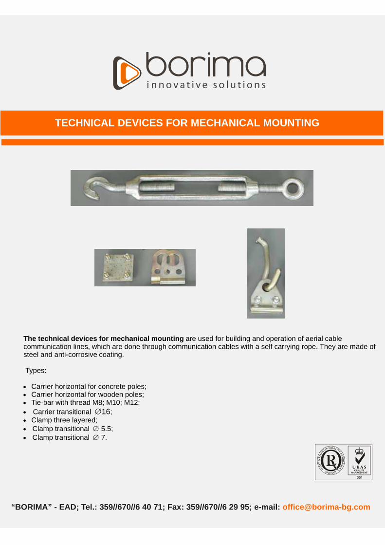
TECHNICAL DEVICES FOR MECHANICAL MOUNTING
The technical devices for mechanical mounting are used for building and operation of aerial cablecommunication lines, which are done through communication cables with a self carrying rope. They are made ofsteel and anti-corrosive coating.
Types:
Carrier horizontal for concrete poles;Carrier horizontal for wooden poles;Tie-bar with thread M8; M10; M12;Carrier transitional ;Clamp three layered;Clamp transitional ;5.5
••••••
16
• Clamp transitional 7.

“BORIMA” - EAD; tel.: 359//670//6 40 71; fax: 359//670//6 29 95; e-mail: [email protected]
The technical devices for mechanical mounting
TEHNICAL DEVICES FOR MECHANICAL MOUNTING
Carrier horizontal for concrete polesPart No - 8495
Carrier horizontal for wooden polesPart No - 8463
Carrier transitional 16
Part No L, mm N, mm8496 310 ±2 206 ±18497 400 ±2 305 ±1
Tie-bar with thread 8; 10; 12Part No – according customer request
8 10 12min 290 365 395L max 380 455 490
D 20 20 24 R 10 10 12
Clamp three layeredPart No - 8464
Clamp transitional 5.5Part No - 8465
Clamp transitional 7Part No - 8462

; : :“BORIMA” - EAD Tel. 359//670//6 40 71; Fax 359//670//6 29 95; e-mail: [email protected]
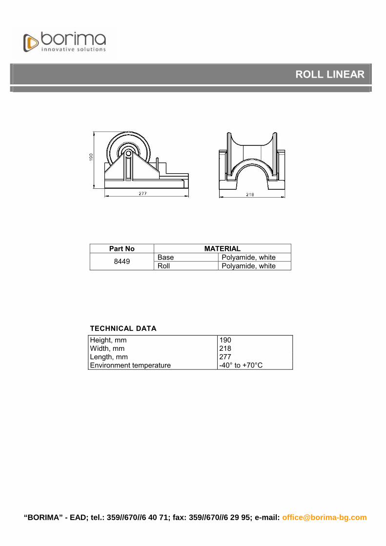
ROLL LINEAR
Roll linear
roll linear
is used for mechanical laying of the cables at building of cable traces. It assists the cables stringingfor getting of their maximum permissible length and the usage of minimum number of joint closures. It is made ofpolyamide.
The consists of:A base made of polyamide, on which there are four openings for fixing to a foundation.A roll fixed with a shaft and bearings to the base.
••
“BORIMA” - EAD; tel.: 359//670//6 40 71; fax: 359//670//6 29 95; e-mail: [email protected]
ROLL LINEAR
Part No MATERIALBase Polyamide, white8449 Roll Polyamide, white
TECHNICAL DATAHeight, mm 190Width, mm 218Length, mm 277Environment temperature -40° to +70°Ñ

; : :“BORIMA” - EAD Tel. 359//670//6 40 71; Fax 359//670//6 29 95; e-mail: [email protected]
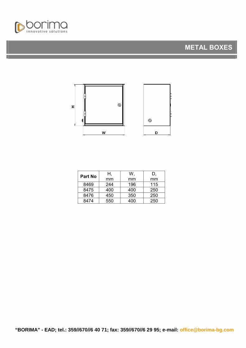
METAL BOXES
The metal boxes can be used according to the needs of the customers. They are made of sheet material withthickness from 1 to 1.5 mm.The thickness of the sheet material and overall dimensions of the boxes can be manufactured according tocustomers' request.The coating is made of powder painting with a colour in compliance with the customers' request.They are equipped with secret locks.
“BORIMA” - EAD; tel.: 359//670//6 40 71; fax: 359//670//6 29 95; e-mail: [email protected]
METAL BOXES
Part No H,mm
W,mm
D,mm
8469 244 196 1158475 400 400 2508476 450 350 2508474 550 400 250

e-mail:“BORIMA”-EAD; tel. 359//670//6 40 71; fax 359//670//6 29 95; [email protected]
TERMINAL FIBER OPTIC BOX
The serves to organize and protect the fiber optic cable joints from dust andmechanical damages.The design allows easy access to all joints and connections.It is made of metal sheets with 0.8 mm thickness.The coating is powder paint color is according to customer's request.
The is designed for four pieces of optical fibers.
consists of:Body ;Cover;
The can be made with or without equipment.The equipment includes:
Heat shrinkable protective sleeve Holder 1 piece;SC duplex adapter 2 pieces;Connectors 2 pieces;Heat shrinkable protective sleeves 4 pieces;
The dimensions and type of equipment can be made according tocustomer's request.
Terminal Fiber Optic Box
Terminal Fiber Optic Box
The Terminal Fiber Optic Box
Terminal Fiber Optic Box
Terminal Fiber Optic Box's
-
••
••••

“BORIMA” - EAD; tel.359//670//6 40 71; fax 359//670//6 29 95; e-mail: [email protected]
TERMINAL FIBER OPTIC BOX
Part No W,mm
W1,mm
H,mm
D,mm
8309 155 200 110 33

e-mail:“BORIMA”-EAD; tel. 359//670//6 40 71; fax 359//670//6 29 95; [email protected]
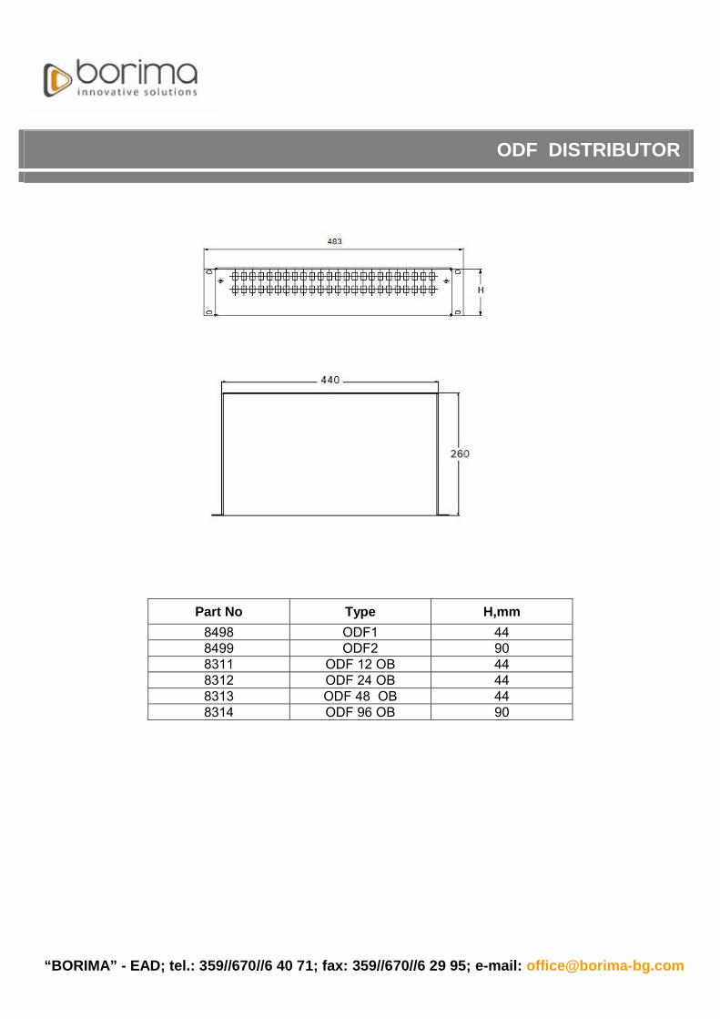
ODF DISTRIBUTOR
ODF Distributor
Types of ODF Distributors
ODF Distributor
ODF
The ODF
serves to organize and protect fiber optic connections from dust and mechanicaldamages.The design allows easy access to all connections and joints.It is made of metal sheets with 1 mm thickness.The coating is powder paint color is according to customer's request.
according to their capacity.For 12 optical fibers;For 24 optical fibers;For 48 optical fibers;For 96 optical fibers;
consists of :Body ;Cover;Locks 2 pieces - according to customer's request;Leads - according to customer's request.
can be made with or without equipment.The equipment includes:
Splice cassettes their number depend on the capacity;SC duplex adaptor - the number depends on the capacity;Connectors - the number depends on the capacity;Heat shrinkable protection sleeves the number depends on the capacity;
Distributor's dimensions and type of equipmentcan be made according to customer's request.
-
-
-
••••
••••
••••
-
“BORIMA” - EAD; tel.: 359//670//6 40 71; fax: 359//670//6 29 95; e-mail: [email protected]
ODF DISTRIBUTOR
Part No Type H,mm8498 ODF1 448499 ODF2 908311 ODF 12 448312 ODF 24 448313 ODF 48 448314 ODF 96 90

e-mail:“BORIMA”-EAD; tel. 359//670//6 40 71; fax 359//670//6 29 95; [email protected]
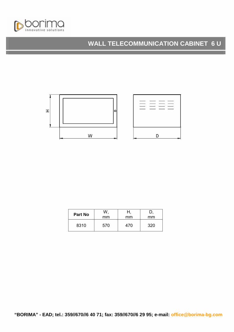
WALL TELECOMMUNICATION CABINET 6 U
The is designed for installation of 6 ODF distributors.
The consists of:Assembly Columns 1.2 mm sheet steel;Upper and Lower Panels 1.2 mm sheet steel;Side opening Panels 1.2 mm sheet steel;Rear Panel 1.2 mm sheet steel;Door metal frame made of lexiglas or sheet steel 1.2 mm ;19” mounting rail - two pieces, 1.2 sheet steel;Safety lock;
The coating is powder paint color is according to customer's request.
It is designed for indoor installation.There is a possibility for a fan to be mounted inside the Cabinet.The design allows easy access to all ODF distributors.
The can be made to 45 U according to customer's request.
Wall Telecommunication Cabinet 6U
Wall Telecommunication Cabinet 6U
Wall Telecommunication Cabinet
•••••••
--
--
p
and
“BORIMA” - EAD; tel.: 359//670//6 40 71; fax: 359//670//6 29 95; e-mail: [email protected]
WALL TELECOMMUNICATION CABINET 6 U
Part No W,mm
H,mm
D,mm
8310 570 470 320

e-mail:“BORIMA”-EAD; tel. 359//670//6 40 71; fax 359//670//6 29 95; [email protected]
FIBER OPTIC CLOSURE
The Fiber Optic Closure
:
ypes of Fiber Optic Closure :
Equipment:
is designed to provide protection for all types of joints of fiber optic cablesfrom mechanical effects and environment influences.The closure may be used in underground, buried, ground or aerial installation.
The fiber optic closure consists ofA Body made of polyamide;A Base with four round and one oval entry port made of polyamide;Closing clamp which is easy to work with when you open and lock the closure made of polyamide;
plice cassette of polyamide;Splice cassette and cover made of ABS ;Rubber sealing ring placed between the body and base;
according to their capacityFor 12 optical fibers;For 24 optical fibers;For 48 optical fibers;For 96 optical fibers;
Heat shrinkable protective sleeves their number depends on the capacity they serve to protect thejoint optical fibers;
Heat shrinkable sleeve 5 pieces, which seals the incoming cables;Branch-off clip 1 piece is used for branching cables;Aluminium foil;Spanner;Grounding cable;Pig tails;Metal Holder 1 piece is used for ground closure installation ;
••••••
••••
•
•••••••
--
-Holder for s - made
-
The are
- ,
--
-
t

“BORIMA” - EAD; tel.: 359//670//6 40 71; fax: 359//670//6 29 95; e-mail: [email protected]
The closure is designed for fiber optic cables with outer diameter up to 18 mm.The closure is made of black impact resistant polyamide and flammability class V0 in compliance with UL 94.
Installation:When the temperature of the environment is from - 5°C to +50°C and relative humidity is to 98 % condensed moisture.
Part No Type of Closure Number of cassettes for optical fibers
8315 For 12 optical fibers 18316 For 24 optical fibers 18317 For 48 optical fibers 28318 For 96 optical fibers 4
FIBER OPTIC CLOSURE

; : :“BORIMA” - EAD Tel. 359//670//6 40 71; Fax 359//670//6 29 95; e-mail: [email protected]
Branch off kits are designed for branching cables of heat shrinkable closures. The three types of Branchingkits (BOKT) cover all sizes of cables. Three-finger construction helps in perfect branching and reliable sealing,as the middle finger is coated with hot melt adhesive. It is supplied in kit form with all necessary components forbranching.One Branching kit (BOKT) is required for branching two cables at one end.
Branch off clipCleaning tissueAluminium cable foilShield continuity wireAbrasive strip
Two-finger clipThree-finger clip MediumThree-finger clip Small
•••••
•••
The KIT contains:
Types:
BRANCH OFF KIT FOR CABLE BRANCHING SYSTEM (BOKT)

“BORIMA” - EAD; tel.: 359//670//6 40 71; fax: 359//670//6 29 95; e-mail: [email protected]
Branch off kits Types
BRANCH OFF KIT FOR CABLE BRANCHING SYSTEM (BOKT)
The two-finger clip consists of two details with teeth in their joint parts. It is made of polyamide.Part No - 8202
Three-finger clip – Medium is made of aluminium alloy and it is with epoxy-polyester coating. The middle finger is coated with hot melt adhesive.Part No - 8206
Three-finger clip – Small is made of aluminium alloy and it is with epoxy-polyester coating. The middle finger is coated with hot melt adhesive.Part No - 8207

e-mail:“BORIMA”-EAD; tel. 359//670//6 40 71; fax 359//670//6 29 95; [email protected]
TELEPHONE BOOTH
facilityon
on
The Telephone Booth is designed for mounting telephones sets and as advertising .There is a possibility for setting two telephones left or right side, in accordance with the
requirements of the customer.On the Telephone Booth there is also an advertising part on which can easily be put and
respectively replace advertising posters. The advertising part is lit up by light-emitting diodes (LED).It is made of section steel with hot galvanized coating. It is painted in accordance with the
requirement of the customer.It is mounted reinforced concrete foundation.

“BORIMA” - EAD; tel.359//670//6 40 71; fax 359//670//6 29 95; e-mail: [email protected]
TELEPHONE BOOTH
Part No H,mm
W,mm
D,mm
8525 2450 1500 9555