catalogue 2019 catalogue - stewarts and lloyds irrigation
TRANSCRIPT

Catalogue 2019Catalogue

Catalogue 2019

Plasson’s innovative products revolutionized the way of connecting polyethylene pipes inthe 1960’s. We started with fittings for agricultural irrigation and later developed solutions forurban water distribution.
Nowadays, water delivery systems in many of the world’s great cities owe their excellence toPlasson’s innovative research and development.
Plasson ensures superior designs and products, the widest range of fittings and adaptors anda genuine commitment to quality, delivery and service.
Plasson continues to strive for the future environment. By using Plasson products, you help usto invest in our vision of a world where clean, pure water will be everyone’s birthright.
En los años sesenta Plasson revolucionó la forma de conectar tubos de polietileno. En el principio fueron conectores para uso agricola a partir de los cuales se desarrollaran, más tarde, productos para distribución de agua en sistemas municipales.
Hoy en día, algunas de las más grandes ciudades del mundo, deben la excelencia de sus sistemas de suministro de aguas a la investigación y desarrollo de Plasson.
Plasson no ha ahorrado esfuerzos para desarrollar, mediante excelente diseño, empleando los mejores materiales y con un total compromiso de calidad y servicio, la más amplia línea de conectores y adaptadores.
Nuestro compromiso con el medio ambiente es permanente. Comprando productos Plasson, usted está ayudándonos a seguir invirtiendo en nuestra visión de un mundo donde agua limpia y pura es un derecho natural de todos.

Content
Mechanical Fittings
ElectroFusion Fittings
Series 1 Fittings
Silver Line Fittings
6 - 87
90 - 178
182 - 212
214 - 231

4

5


8 MECHANICAL FITTINGS

9MECHANICAL FITTINGS
MEC
HA
NIC
AL
FITT
ING
SEL
ECTR
OFU
SIO
N F
ITTI
NG
SSE
RIES
1SI
LVER
LIN
E
Compression Fittings for PE pipe
Conversion & Adaptor Sets from PE to Copper / UPVC / PP / Lead / Galvanised Pipe
Pipe Conversion Chart
Accessories for Compression Fittings
Fittings for 160mm PE Pipe
Saddles
BSP Threaded Fittings
Valves
Technical Specifications
Installation Instructions for Compression Fittings
Installation Instructions for Pipe Adaptors Conversion Sets
Installation Instructions for Plass4 and Copper Pipe Adaptor (Universal Adaptor)
Content
MECHANICAL FITTINGS16 - 37
38 - 45
46
47 - 51
52 - 55
56 - 59
60 - 65
66 - 74
75 - 79
80 - 82
83 - 85
86 - 87
Accesorios Mecánicos
Juegos de conversio’n y adaptadores de PE a Cobre / PVC rígido/ PP / Plomo / Tubos galvanizados
Gráfico de conversiones para tuberias
Recambios y Accesorios
Accesorios para tuberias de PE 160mm
Collarines
Accesorios roscados (BSP)
Válvulas
Detalles técnicos
Instrucciones de montaje (para accesorios de pression)
Instrucciones de montaje (para adaptadores de tubos) Juegos de conversio’n
Instrucciones de montaje de Plass4 & tubo de cobre y adaptador Universal
MECHANICAL FITTING16 - 37
38 - 45
46
47 - 51
52 - 55
56 - 59
60 - 65
66 - 74
75 - 79
80 - 82
83 - 85
86 - 87

10 MECHANICAL FITTINGS
Technical catalogue 2019 | Content
07010
Page 16 CouplingEnlace recto
07610
Page 16 Repair CouplingEnlace recto de reparación
07110
Page 17 Reducing CouplingEnlace Recto Reductor
07020
Page 18 Male AdaptorEnlace mixto rosca macho
07720
Page 19 Male Integral Brass ThreadEnlace mixto rosca macho de laton
07030
Page 20 Female AdaptorEnlace mixto rosca hembra
0703GO
Page 20 Female Adaptor GEnlace mixto rosca hembra G
07320
Page 21 Shouldered AdaptorAdaptador minero
07120
Page 21 End PlugTapón final
07050
Page 22 90º ElbowCodo de 90º
07510
Page 22 90º Reducing ElbowCodo de 90º reductor
07850
Page 23 90º Elbow with Threaded Male OfftakeCodo de 90º compresión rosca macho
07770
Page 24 90º Elbow with Male Integral BrassCodo de 90º con macho integral de latón
07150
Page 25 90º Elbow with Threaded Female OfftakeCodo de 90º compresión rosca hembra
07060
Page 26 45º ElbowCodo de 45º
07450
Page 26 45º Elbow with Threaded Male OfftakeCodo de 45º compresión rosca macho
07350
Page 27 90º Elbow AdaptorCodo espiga
07750
Page 27 Wall Plate ElbowCodo de aplicación mural
Compression Fittings
11MECHANICAL FITTINGS
MEC
HA
NIC
AL
FITT
ING
SEL
ECTR
OFU
SIO
N F
ITTI
NG
SSE
RIES
1SI
LVER
LIN
E
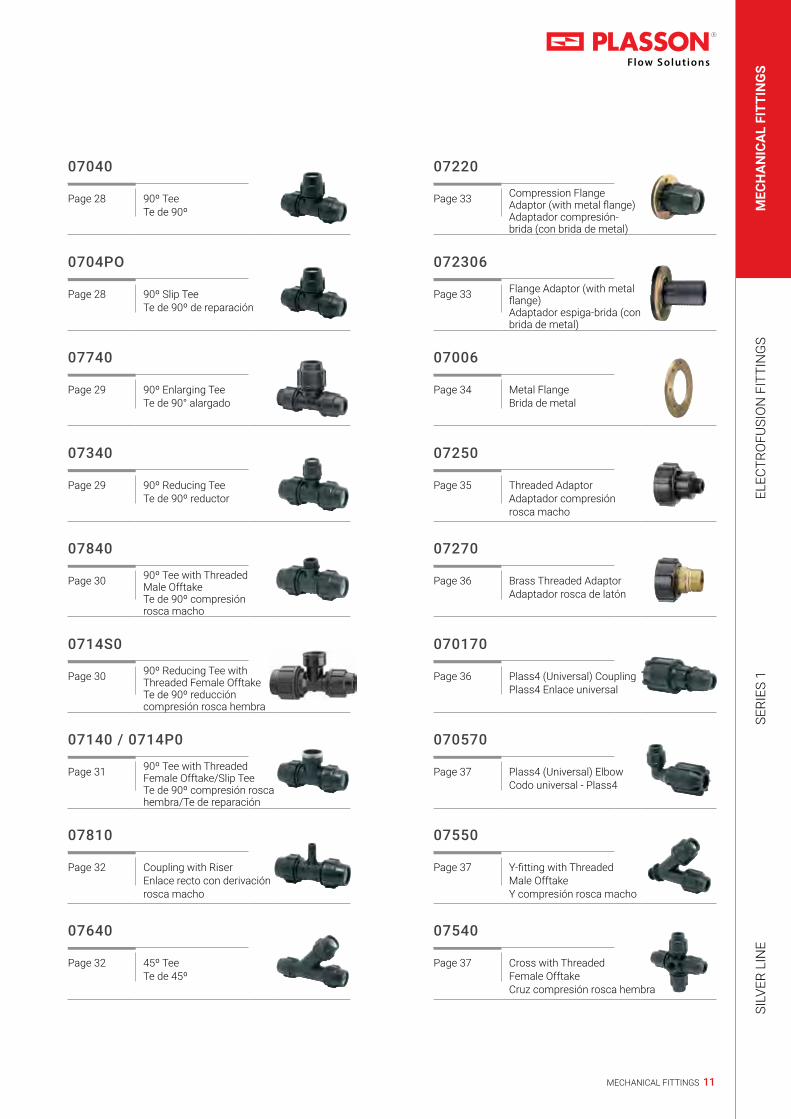
07040
Page 28 90º TeeTe de 90º
0704PO
Page 28 90º Slip TeeTe de 90º de reparación
07740
Page 29 90º Enlarging TeeTe de 90° alargado
07340
Page 29 90º Reducing TeeTe de 90º reductor
07840
Page 30 90º Tee with Threaded Male OfftakeTe de 90º compresión rosca macho
0714S0
Page 30 90º Reducing Tee with Threaded Female OfftakeTe de 90º reducción compresión rosca hembra
07140 / 0714P0
Page 31 90º Tee with Threaded Female Offtake/Slip TeeTe de 90º compresión rosca hembra/Te de reparación
07810
Page 32 Coupling with RiserEnlace recto con derivación rosca macho
07640
Page 32 45º TeeTe de 45º
07220
Page 33 Compression Flange Adaptor (with metal flange)Adaptador compresión-brida (con brida de metal)
072306
Page 33 Flange Adaptor (with metal flange)Adaptador espiga-brida (con brida de metal)
07006
Page 34 Metal FlangeBrida de metal
07250
Page 35 Threaded AdaptorAdaptador compresión rosca macho
07270
Page 36 Brass Threaded AdaptorAdaptador rosca de latón
070170
Page 36 Plass4 (Universal) CouplingPlass4 Enlace universal
070570
Page 37 Plass4 (Universal) ElbowCodo universal - Plass4
07550
Page 37 Y-fitting with Threaded Male OfftakeY compresión rosca macho
07540
Page 37 Cross with Threaded Female OfftakeCruz compresión rosca hembra

12 MECHANICAL FITTINGS
Technical catalogue 2019 | Content
17610
Page 39 Universal Slip Repair CouplerEnlace Universal de reparación y de transición
071209
Page 39 Plug AdaptorTapón ciego
07950
Page 40 Pipe Liner for PE SDR 11 PipeRefuerzo de tubos
07896
Page 40 Adaptor for Copper and Imperial UPVCAdaptador universal para tubos de cobre y UPVC imperial
07930
Page 41 Reducing SetJuego reductor
07003Q
Page 41 Split Ring for UPVC and PP pipes
07940
Page 42 Modular AdaptorAdaptador modular
0701C6
Page 42 Copper Pipe AdaptorAdaptador tudo de cobre
07970
Page 42 Grip Ring for UPVC and PP PipeCasquillo de apriete para tubos de UPVC y PP
074380
Page 43 Conversion Set for Copper PipeJuego adaptador para tubos de cobre
0701QQ
Page 43 Coupling for PVC PipeEnlace recto para tubo de PVC
077802
Page 44 Conversion Set for Lead PipeJuego adaptador para tubos de plomo
078908
Page 44 Converter Rubber Adaptor for Galvanised PipeConversor Adaptador de goma para tubos de acero galvanizado
078907
Page 45 Conversion Set Adaptor for Galvanised PipeJuego conversor de compresion para tubos de acero galvanizado
Accessories for Compression Fittings07004
Page 47 NutRacor
07002
Page 47-49 O - Ring / SealJunta tórica / sello
07003
Page 49-50 Split RingCasquillo de apriete
Conversion & Adaptor Sets

13MECHANICAL FITTINGS
MEC
HA
NIC
AL
FITT
ING
SEL
ECTR
OFU
SIO
N F
ITTI
NG
SSE
RIES
1SI
LVER
LIN
E
07005
Page 50 InsertInserto de PP
18960
Page 51 Chamfer Tool for PE PipesHerramienta para biselar
07990
Page 51 Plasson WrenchLlave Plasson
Fittings for 160mm Pipes070106
Page 52 CouplingEnlace recto
076106
Page 52 Repair CouplingEnlace recto de reparación
070406
Page 53 90º TeeTe de 90º
070506
Page 53 90º ElbowCodo de 90º
072206
Page 54 Compression Flange Adaptor (with metal flange)Adaptador compresión-brida (con brida de metal)
072306
Page 54 Flange Adaptor (with metal flange)Adaptador brida-espiga (con brida de metal)
073206
Page 55 Shouldered AdaptorAdaptador minero
17006
Page 55 Metal FlangeBrida Meta’lica
Threaded Outlet Saddles16076
Page 56 Saddle Single OutletCollarín simple
16176
Page 57 Saddle Double OutletCollarín doble
Tapping Saddles & Valves18680
Page 58 Mechanical Tapping ValveValvula Mecanica con salida rotatoria Tapper®
16540
Page 59 Tapper® - for PVC & PE PipesCollarin con salida rotatoria Tapper® para tubos de PVC y de PE

14 MECHANICAL FITTINGS
Technical catalogue 2019 | Content
050107
Page 60 Threaded SocketManguito rosca hembra x hembra
050207
Page 60 Threaded Reducing BushingManguito reductor hembra x macho
050407
Page 61 90º Threaded TeeTe de 90º rosca hembra
050507
Page 61 90º Threaded ElbowCodo de 90º rosca hembra
051507
Page 62 90º Threaded Elbow Male x FemaleCodo roscado-macho x hembra
050605
Page 62 Threaded Reducing NippleMachón doble reductor
050607
Page 63 Threaded NippleMachón doble
050707
Page 63 Threaded CapTapón rosca hembra
051107
Page 64 Threaded Reducing SocketManguito reductor rosca hembra - hembra
051607
Page 64 Threaded RiserEspiga roscada
051707
Page 65 Threaded PlugTapón rosca macho
Valves03703
Page 67 Ball ValveVálvula esférica
03405
Page 67 Threaded StoptapVálvula de línea rosca hembra
03406
Page 67 Compression StoptapVálvula de linea compresión
03048
Page 68 Angle Seat Valve Threaded x CompressionVálvula de asiento angular - compresión - rosca
03047
Page 68 Angle Seat Valve (seal NBR), Threaded Inlet & OutletVálvula de asiento angular (sello NBR), roscas macho
03049
Page 69 Angle Seat Valve (seal FPM), Threaded Inlet & OutletVálvula de asiento angular (sello FPM), roscas macho
BSP Threaded Fittings

15MECHANICAL FITTINGS
MEC
HA
NIC
AL
FITT
ING
SEL
ECTR
OFU
SIO
N F
ITTI
NG
SSE
RIES
1SI
LVER
LIN
E
03046
Page 69 Angle Seat Valve Compression Inlet & OutletVálvula de asiento angular compresión
03067
Page 70 Check Valve (seal EPDM), Threaded Inlet & OutletVálvula antirretorno (Juntas EPDM), roscas macho
033801
Page 70 Fixed Ratio Pressure Reducer
0220
Page 70 Pressure Regulator
03039
Page 71 Quick Coupling ValveVálvula de acople rápido
03139
Page 71 Key for Quick Coupling Valve 3039Conexión de acople rápido
03226 / 03227
Page 71 Check Valve InsertValvula de control
3589
Page 72 BSPT Record for Water MeterTubo y tuerca BSPT
03510
Page 72 Water Meter ManifoldSoporte para control de flujo de agua
036010
Page 72 Coupling
036020
Page 73 PP Ball Valve Male Adaptor
036030
Page 73 PP Ball Valve Female Adaptor
Quarter Turn Valves03010
Page 74 Male Threaded X CompressionRosca Macho-/Compresíon
03012
Page 74 Male Threaded X Female ThreadedRosca Macho-/Rosca Hembra
03017
Page 74 Compression X CompressionCompresíon
ISRAEL POLAND FRANCE AUSTRIA AUSTRIA ITALY
SWITZERLAND NETHERLANDS NETHERLANDS GERMANY GERMANY RUSSIA RUSSIA
AUSTRALIA

16 MECHANICAL FITTINGS
Technical catalogue 2019 | Compression Fittings
Coupling 07010
Enlace recto
H
dE
II
Product Code Size d x d E H I UB UC W
070106016 16 x 16 39 105 50 10 400 520701060200A 20 x 20 48 122 59 10 200 930701060250A 25 x 25 54 126 61 10 180 1160701060320A 32 x 32 64 145 71 5 100 1810701060400A 40 x 40 82 177 87 — 75 3100701060500A 50 x 50 96 201 98 — 45 4570701060630A 63 x 63 113 230 113 — 30 7410701060750A 75 x 75 134 278 138 — 16 11830701060900A 90 x 90 154 335 165 — 10 18980701061100A 110 x 110 181 393 194 — 5 31290701061250A 125 x 125 212 460 225 — 3 5347
Repair Coupling 07610
Enlace recto de reparación
H
dE
I
Product Code Size d x d E H I UB UC W
0761060200A 20 x 20 48 122 78 10 240 1410761060250A 25 x 25 54 136 90 10 150 1190761060320A 32 x 32 64 174 120 5 80 2020761060400A 40 x 40 82 215 148 — 55 3600761060500A 50 x 50 96 244 158 — 30 5360761060630A 63 x 63 113 270 170 — 24 8360761060750A 75 x 75 134 278 139 — 16 11780761060900A 90 x 90 154 335 168 — 10 18520761061100A 110 x 110 181 393 197 — 5 30980761061250A 125 x 125 212 460 265 — 3 5318

17MECHANICAL FITTINGS
MEC
HA
NIC
AL
FITT
ING
SEL
ECTR
OFU
SIO
N F
ITTI
NG
SSE
RIES
1SI
LVER
LIN
E
Reducing Coupling 07110
Enlace Recto Reductor
H
d EE1 d1
II1
Product Code Size d x d1 E E1 H I I1 UB UC W
0711060200160A 20 x 16 48 39 111 57 50 10 300 740711060250160A 25 x 16 54 39 113 58 50 10 220 880711060250200A 25 x 20 54 48 119 58 57 10 200 1000711060320200A 32 x 20 64 48 140 67 57 5 150 1420711060320250A 32 x 25 64 54 133 67 58 5 120 1430711060400250A 40 x 25 82 54 156 84 58 — 90 2190711060400320A 40 x 32 82 64 156 84 67 — 90 2450711060500250A 50 x 25 96 54 176 93 58 — 70 3050711060500320A 50 x 32 96 64 175 98 62 — 70 3320711060500400A 50 x 40 96 82 184 93 84 — 60 3810711060630250A 63 x 25 113 54 193 110 58 — 50 4610711060630320A 63 x 32 113 64 197 110 62 — 45 4860711060630400A 63 x 40 113 82 208 110 82 — 40 5460711060630500A 63 x 50 113 96 214 110 93 — 36 5740711060750500A 75 x 50 134 96 245 132 98 — 22 8460711060750630A 75 x 63 134 113 252 132 112 — 20 9600711060900630A 90 x 63 154 113 292 170 115 — 14 14150711060900750A 90 x 75 154 134 330 170 134 — 12 16090711061100900A 110 x 90 181 154 378 194 162 — 6 2643

18 MECHANICAL FITTINGS
Technical catalogue 2019 | Compression Fittings
Male Adaptor 07020
Enlace mixto rosca macho
H
dE R
I I2
Product Code Size d x R E H I I2 UB UC W
070206016003 16 x 3/8” 39 76 59 13 10 600 33070206016005 16 x 1/2” 39 79 59 16 10 500 34070206016007 16 x 3/4” 39 79 59 17 10 500 350702060200050A 20 x 1/2” 48 92 71 17 10 350 580702060200070A 20 x 3/4” 48 92 71 18 10 350 590702060200100A 20 x 1” 48 86 52 20 10 350 600702060250050A 25 x 1/2” 54 94 72 17 10 250 680702060250070A 25 x 3/4” 54 95 72 18 10 250 730702060250100A 25 x 1” 54 97 72 20 10 250 790702060320070A 32 x 3/4” 64 106 83 18 5 150 1130702060320100A 32 x 1” 64 107 83 20 5 150 1220702060320130A 32 x 1 1/4” 64 110 83 22 5 150 1140702060320150A 32 x 1 1/2” 64 110 83 22 5 140 1270702060400100A 40 x 1” 82 118 91 20 — 110 1840702060400130A 40 x 1 1/4” 82 117 90 22 — 110 1850702060400150A 40 x 1 1/2” 82 117 90 22 — 100 1850702060400200A 40 x 2” 82 123 91 26 — 100 2080702060500100A 50 x 1” 96 133 106 20 — 70 2660702060500130A 50 x 1 1/4” 96 136 106 22 — 70 2660702060500150A 50 x 1 1/2” 96 136 109 22 — 70 2770702060500200A 50 x 2” 96 140 109 26 — 65 2840702060630130A 63 x 1 1/4” 113 154 123 22 — 48 4430702060630150A 63 x 1 1/2” 113 154 123 22 — 48 4510702060630200A 63 x 2” 113 167 123 26 — 48 4610702060630250A 63 x 2 1/2” 113 160 123 29 — 45 4590702060750200A 75 x 2” 132 188 150 26 — 28 7100702060750250A 75 x 2 1/2” 132 191 150 29 — 28 7120702060750300A 75 x 3” 132 195 150 33 — 25 7180702060900200A 90 x 2” 152 227 170 26 — 16 11230702060900250A 90 x 2 1/2” 152 229 170 29 — 16 11420702060900300A 90 x 3” 152 232 170 33 — 16 11330702060900400A 90 x 4” 152 239 170 40 — 16 12260702061100200A 110 x 2” 181 261 213 26 — 10 18450702061100300A 110 x 3” 181 256 213 34 — 10 18500702061100400A 110 x 4” 181 265 213 42 — 8 1872

19MECHANICAL FITTINGS
MEC
HA
NIC
AL
FITT
ING
SEL
ECTR
OFU
SIO
N F
ITTI
NG
SSE
RIES
1SI
LVER
LIN
E
Male Integral Brass Thread 07720
Enlace mixto rosca macho de laton
H
dE R
I
I2
Product Code Size d x R E H I I2 UB UC W
0772060320070A 32 x 3/4” 64 139 83 18 1 100 2400772060320100A 32 x 1” 64 141 83 20 1 100 2760772060320130A 32 x 1 1/4” 64 142 83 22 1 75 3000772060320150A 32 x 1 1/2” 64 142 83 22 1 100 3300772060400070A 40 x 3/4” 82 149 91 18 1 65 4130772060400100A 40 x 1” 82 151 91 20 1 65 4130772060400130A 40 x 1 1/4” 82 154 91 22 1 65 4280772060400150A 40 x 1 1/2” 82 153 91 22 1 55 4280772060500100A 50 x 1” 96 169 106 20 1 45 5390772060500130A 50 x 1 1/4” 96 172 106 22 1 45 5630772060500150A 50 x 1 1/2” 96 172 106 22 1 45 5860772060630130A 63 x 1 1/4” 113 190 123 22 1 30 8420772060630150A 63 x 1 1/2” 113 190 123 22 1 30 8740772060630200A 63 x 2” 113 194 123 26 1 30 855

20 MECHANICAL FITTINGS
Technical catalogue 2019 | Compression Fittings
Female Adaptor 07030
Enlace mixto rosca hembra
H
dE Rp
I I2
Product Code Size d x Rp E H I I2 UB UC W
070306016005 16 x 1/2” 39 73 52 19 10 500 36070306016007 16 x 3/4” 39 75 53 19 10 500 360703060200050A 20 x 1/2” 48 82 60 19 10 350 600703060200070A 20 x 3/4” 48 82 60 19 10 350 580703060200100A 20 x 1” 48 92 57 21 10 300 680703060250070A 25 x 3/4” 54 88 63 21 10 250 830703060250100A 25 x 1” 54 88 63 21 10 250 780703060320070A 32 x 3/4” 64 94 73 19 5 150 1070703060320100A 32 x 1” 64 94 69 21 5 150 1150703060320130A 32 x 1 1/4” 64 96 67 25 5 140 1400703060400100A 40 x 1” 82 112 84 21 — 110 1780703060400130A 40 x 1 1/4” 82 114 84 25 — 110 2020703060400150A 40 x 1 1/2” 82 114 84 25 — 100 2250703060500130A 50 x 1 1/4” 96 123 93 25 — 75 2760703060500150A 50 x 1 1/2” 96 123 93 25 — 70 2770703060500200A 50 x 2” 96 128 93 30 — 70 2940703060630130A 63 x 1 1/4” 113 139 110 25 — 48 4170703060630150A 63 x 1 1/2” 113 139 110 25 — 48 4380703060630200A 63 x 2” 113 148 110 30 — 48 4430703060750200A 75 x 2” 132 175 132 30 — 28 6620703060750250A 75 x 2 1/2” 132 170 132 33 — 28 6830703060900200A 90 x 2” 154 213 183 30 — 16 11380703060900300A 90 x 3” 154 223 183 40 — 16 12040703060900400A 90 x 4” 154 243 183 52 — 12 14440703061100300A 110 x 3” 181 261 213 40 — 8 19190703061100400A 110 x 4” 181 271 213 50 — 8 2048
Female Adaptor G 0703G0*
Enlace mixto rosca hembra G
H
dE G
I I2
Product Code Size d x G E H I I2 UB UC W
0703G60250070A 25 x 3/4” 54 88 63 12 10 250 830703G60250100A 25 x 1” 54 88 63 14 10 250 780703G60320100A 32 x 1” 64 89 72 14 5 150 115
* For connecting parallel male thread | * Para conectar rosca macho paralelo

21MECHANICAL FITTINGS
MEC
HA
NIC
AL
FITT
ING
SEL
ECTR
OFU
SIO
N F
ITTI
NG
SSE
RIES
1SI
LVER
LIN
E
Shouldered Adaptor 07320
Adaptador minero
H
dE B
IL
Product Code Size d x DN (inch) E I L H B UB UC W
0732060500200A 50 x 50 (2”) 96 109 16 138 67 — 65 2930732060630200A 63 x 50 (2”) 113 123 16 156 67 — 45 4370732060900400A 90 x 100 (4”) 154 170 16 231 123 — 16 12130732061100400A 110 x 100 (4”) 181 213 16 255 123 — 8 1874
End Plug 07120
Tapón final
H
dE
I
Product Code Size d E I H UB UC W
0712060200A 20 48 74 79 10 350 570712060250A 25 54 77 82 10 250 720712060320A 32 64 87 92 5 180 1080712060400A 40 82 97 102 — 110 1860712060500A 50 96 114 121 — 75 2700712060630A 63 113 122 145 — 45 4480712060750A 75 134 155 172 — 28 7100712060900A 90 154 170 212 — 16 11390712061100A 110 181 213 231 — 10 1835

22 MECHANICAL FITTINGS
Technical catalogue 2019 | Compression Fittings
90º Elbow 07050
Codo de 90°
A
d E
I
Product Code Size d x d E I A UB UC W
070506016 16 x 16 39 50 63 10 350 570705060200A 20 x 20 48 56 73 10 200 950705060250A 25 x 25 54 58 79 10 150 1220705060320A 32 x 32 64 67 93 5 100 1870705060400A 40 x 40 82 82 108 — 60 3410705060500A 50 x 50 96 93 127 — 35 4970705060630A 63 x 63 113 110 151 — 24 8380705060750A 75 x 75 134 132 178 — 12 13040705060900A 90 x 90 154 162 217 — 8 21680705061100A 110 x 110 181 194 292 — 4 3810
90º Reducing Elbow 07510
Codo de 90° reductor
A1
E1d1
AI
I1
dE
Product Code Size d x D1 E E1 I I1 A A1 UB UC W
0751060250200A 25 x 20 54 48 58 57 90 75 10 180 114

23MECHANICAL FITTINGS
MEC
HA
NIC
AL
FITT
ING
SEL
ECTR
OFU
SIO
N F
ITTI
NG
SSE
RIES
1SI
LVER
LIN
E
90º Elbow with Threaded Male Offtake 07850
Codo de 90° compresión rosca macho
A
Ed
A1
I2
I
R
Product Code Size d x R E I I2 A A1 UB UC W
0785060200050A 20 x 1/2” 48 57 17 74 41 10 350 550785060200070A 20 x 3/4” 48 57 18 76 43 10 300 640785060250050A 25 x 1/2” 54 58 17 85 47 10 240 700785060250070A 25 x 3/4” 54 58 18 90 48 10 250 790785060250100A 25 x 1” 54 58 20 90 54 10 240 840785060320070A 32 x 3/4” 64 67 18 104 55 5 140 1160785060320100A 32 x 1” 64 67 20 104 55 5 140 1280785060320130A 32 x 1 1/4” 64 67 22 104 58 5 140 1350785060400100A 40 x 1” 82 84 20 124 60 — 90 1960785060400130A 40 x 1 1/4” 82 84 22 124 66 — 90 2050785060400150A 40 x 1 1/2” 82 84 22 124 66 — 80 2200785060500100A 50 x 1” 96 93 20 140 71 — 55 2940785060500130A 50 x 1 1/4” 96 93 22 144 74 — 55 3350785060500150A 50 x 1 1/2” 96 93 22 144 74 — 55 3210785060500200A 50 x 2” 96 93 26 144 76 — 55 3730785060630130A 63 x 1 1/4” 113 110 22 168 76 — 35 4510785060630150A 63 x 1 1/2” 113 110 22 168 76 — 35 4680785060630200A 63 x 2” 113 110 26 170 92 — 35 5180785060750250A 75 x 2 1/2” 134 132 30 202 105 — 18 8720785060750300A 75 x 3” 134 132 33 202 110 — 18 8920785060900300A 90 x 3” 154 165 35 233 110 — 12 13000785061100400A 110 x 4” 181 194 42 274 140 — 6 2258

24 MECHANICAL FITTINGS
Technical catalogue 2019 | Compression Fittings
90º Elbow with Male Integral Brass 07770
Code de 90°con macho integral de latón
A1
A
R
I2
Ed
Product Code Size d x R E I I2 A A1 UB UC W
0777060320070A 32 x 3/4” 64 67 18 104 79 1 75 2700777060320100A 32 x 1” 64 67 20 104 81 1 70 2860777060320130A 32 x 1 1/4” 64 67 22 104 82 1 70 3430777060320150A 32 x 1 1/2” 64 67 22 104 82 1 70 3600777060400070A 40 x 3/4” 82 84 18 124 86 1 55 4350777060400100A 40 x 1” 82 84 20 124 88 1 55 4350777060400130A 40 x 1 1/4” 82 84 22 124 90 1 55 4500777060400150A 40 x 1 1/2” 82 84 22 124 89 1 55 4600777060500100A 50 x 1” 96 93 20 144 94 1 40 5920777060500130A 50 x 1 1/4” 96 93 22 144 97 1 40 6130777060500150A 50 x 1 1/2” 96 93 22 144 97 1 40 6130777060630130A 63 x 1 1/4” 113 110 22 168 126 1 27 8950777060630150A 63 x 1 1/2” 113 110 22 168 126 1 27 9550777060630200A 63 x 2” 113 110 26 170 129 1 27 987

25MECHANICAL FITTINGS
MEC
HA
NIC
AL
FITT
ING
SEL
ECTR
OFU
SIO
N F
ITTI
NG
SSE
RIES
1SI
LVER
LIN
E
90º Elbow with Threaded Female Offtake 07150
Codo de 90° compresión rosca hembra
A
Ed
A1
I2
I
Rp
Product Code Size d x Rp E I I2 A A1 UB UC W
071506016005 16 x 1/2” 39 50 19 66 39 10 500 380715060200050A 20 x 1/2” 48 54 19 78 40 10 350 610715060200070A 20 x 3/4” 48 57 19 78 44 10 300 710715060250050A 25 x 1/2” 54 58 18 81 46 10 250 860715060250070A 25 x 3/4” 54 58 19 81 46 10 250 810715060250100A 25 x 1” 54 58 21 83 50 10 220 900715060320070A 32 x 3/4” 64 67 18 95 54 5 150 1430715060320100A 32 x 1” 64 67 21 95 54 5 150 1360715060320130A 32 x 1 1/4” 64 67 25 99 60 5 120 1670715060400100A 40 x 1” 82 84 21 119 52 — 100 2010715060400130A 40 x 1 1/4” 82 84 25 119 62 — 90 2460715060400150A 40 x 1 1/2” 82 84 25 119 62 — 80 2610715060400200A 40 x 2” 82 84 30 119 75 — 65 2930715060500100A 50 x 1” 96 93 21 133 57 — 70 2810715060500130A 50 x 1 1/4” 96 93 25 133 67 — 60 3130715060500150A 50 x 1 1/2” 96 93 25 135 66 — 60 3440715060500200A 50 x 2” 96 93 30 138 85 — 45 3870715060630130A 63 x 1 1/4” 113 110 25 162 65 — 35 4880715060630150A 63 x 1 1/2” 113 110 25 162 69 — 35 5040715060630200A 63 x 2” 113 110 30 160 90 — 35 5590715060750200A 75 x 2” 134 132 30 188 100 — 24 8100715060750250A 75 x 2 1/2” 134 132 36 191 105 — 20 9200715060750300A 75 x 3” 134 132 36 191 105 — 20 956
26 MECHANICAL FITTINGS
Technical catalogue 2019 | Compression Fittings
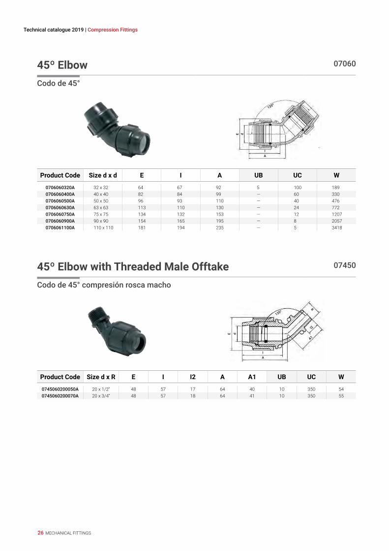
45º Elbow 07060
Codo de 45°
A
dE
I
135º
Product Code Size d x d E I A UB UC W
0706060320A 32 x 32 64 67 92 5 100 1890706060400A 40 x 40 82 84 99 — 60 3300706060500A 50 x 50 96 93 110 — 40 4760706060630A 63 x 63 113 110 130 — 24 7720706060750A 75 x 75 134 132 153 — 12 12070706060900A 90 x 90 154 165 195 — 8 20570706061100A 110 x 110 181 194 235 — 5 3418
45º Elbow with Threaded Male Offtake 07450
Codo de 45° compresión rosca macho
A
dE
I
135º
A1
I2
R
Product Code Size d x R E I I2 A A1 UB UC W
0745060200050A 20 x 1/2” 48 57 17 64 40 10 350 540745060200070A 20 x 3/4” 48 57 18 64 41 10 350 55

27MECHANICAL FITTINGS
MEC
HA
NIC
AL
FITT
ING
SEL
ECTR
OFU
SIO
N F
ITTI
NG
SSE
RIES
1SI
LVER
LIN
E
90º Elbow Adaptor 07350
Codo espiga
A
d E
A1
I
d1
Product Code Size d x d1 E I A A1 UB UC W
0735060400400A 40 x 40 82 84 118 106 — 80 3140735060400500A 40 x 50 82 84 118 120 — 70 2750735060500400A 50 x 40 96 93 136 106 — 60 3080735060500500A 50 x 50 96 93 136 120 — 55 3560735060630400A 63 x 40 113 110 161 106 — 40 4500735060630500A 63 x 50 113 110 161 120 — 35 511
Wall Plate Elbow 07750
Codo de aplicación mural
E
I2
A2 A1I
AH
Rp
d
Product Code Size d x Rp E I I2 A A1 A2 H UB UC W
077506016005 16 x 1/2” 39 50 18 76 40 38 110 1 150 980775060200050A 20 x 1/2” 48 57 18 78 40 38 110 1 150 920775060250070A 25 x 3/4” 54 58 19 81 40 38 120 1 100 115
28 MECHANICAL FITTINGS
Technical catalogue 2019 | Compression Fittings
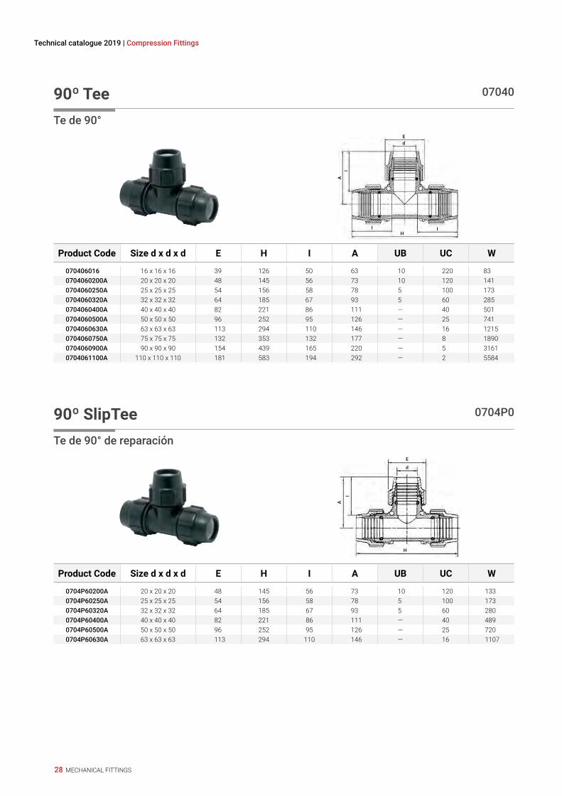
90º Tee 07040
Te de 90°
H
A
I
I
I
dE
Product Code Size d x d x d E H I A UB UC W
070406016 16 x 16 x 16 39 126 50 63 10 220 830704060200A 20 x 20 x 20 48 145 56 73 10 120 1410704060250A 25 x 25 x 25 54 156 58 78 5 100 1730704060320A 32 x 32 x 32 64 185 67 93 5 60 2850704060400A 40 x 40 x 40 82 221 86 111 — 40 5010704060500A 50 x 50 x 50 96 252 95 126 — 25 7410704060630A 63 x 63 x 63 113 294 110 146 — 16 12150704060750A 75 x 75 x 75 132 353 132 177 — 8 18900704060900A 90 x 90 x 90 154 439 165 220 — 5 31610704061100A 110 x 110 x 110 181 583 194 292 — 2 5584
90º SlipTee 0704P0
Te de 90° de reparación
H
A
I
d
E
Product Code Size d x d x d E H I A UB UC W
0704P60200A 20 x 20 x 20 48 145 56 73 10 120 1330704P60250A 25 x 25 x 25 54 156 58 78 5 100 1730704P60320A 32 x 32 x 32 64 185 67 93 5 60 2800704P60400A 40 x 40 x 40 82 221 86 111 — 40 4890704P60500A 50 x 50 x 50 96 252 95 126 — 25 7200704P60630A 63 x 63 x 63 113 294 110 146 — 16 1107

29MECHANICAL FITTINGS
MEC
HA
NIC
AL
FITT
ING
SEL
ECTR
OFU
SIO
N F
ITTI
NG
SSE
RIES
1SI
LVER
LIN
E
90º Enlarging Tee 07740
Te de alargado
H
E1d1
A
II
I1
d E
Product Code Size d x d1 x d E E1 H I I1 A UB UC W
0774060320250A 25 x 32 x 25 54 64 156 58 69 87 5 80 219
90º Reducing Tee 07340
Te de 90° reductor
H
E1d1
A
II
I1dE
Product Code Size d x d1 x d E E1 H I I1 A UB UC W
0734060200160A 20 x 16 x 20 48 39 137 57 50 70 10 150 1250734060250200A 25 x 20 x 25 54 48 150 58 57 74 5 100 1660734060320250A 32 x 25 x 32 64 54 173 67 58 63 5 70 2560734060400250A 40 x 25 x 40 82 54 205 84 58 84 — 45 4120734060400320A 40 x 32 x 40 82 64 207 82 67 97 — 40 4280734060500250A 50 x 25 x 50 96 54 228 93 76 105 — 30 5500734060500320A 50 x 32 x 50 96 64 230 93 67 117 — 30 5900734060500400A 50 x 40 x 50 96 82 236 93 82 114 — 30 6470734060630320A 63 x 32 x 63 113 64 268 113 62 118 — 20 8920734060630400A 63 x 40 x 63 113 82 268 113 84 139 — 20 9620734060630500A 63 x 50 x 63 113 96 275 110 93 132 — 18 10210734060750630A 75 x 63 x 75 132 113 353 132 109 153 — 10 1667

30 MECHANICAL FITTINGS
Technical catalogue 2019 | Compression Fittings
90º Tee with Threaded Male Offtake 07840
Te de 90° compresión rosca macho
H
E dA
I2
II
R
Product Code Size d x R x d E H I I2 A UB UC W
0784060200050A 20 x 1/2” x 20 48 138 56 17 46 10 180 1050784060200070A 20 x 3/4” x 20 48 144 56 18 46 10 180 1080784060250050A 25 x 1/2” x 25 54 146 58 17 48 5 140 1340784060250070A 25 x 3/4” x 25 54 146 58 18 50 5 140 1370784060320100A 32 x 1” x 32 64 170 67 20 58 5 80 2180784060400130A 40 x 1 1/4” x 40 82 205 84 22 71 — 50 3730784060400150A 40 x 1 1/2” x 40 82 205 84 22 71 — 50 3760784060500130A 50 x 1 1/4” x 50 96 230 93 22 77 — 36 5110784060500150A 50 x 1 1/2” x 50 96 230 93 22 77 — 36 5230784060500200A 50 x 2” x 50 96 230 93 26 82 — 36 5230784060630130A 63 x 1 1/4” x 63 113 268 113 22 79 — 20 8210784060630150A 63 x 1 1/2” x 63 113 268 113 22 83 — 20 8280784060630200A 63 x 2” x 63 113 272 110 26 92 — 20 877
90º Reducing Tee with Threaded Female Offtake 0714S0
Te de 90° reducción compresión rosca hembra
H
E d
AE1d1
I1
Rp
Product Code Size d x Rp x d E E1 H L I I1 I2 A UB UC W
0714S60200160A 20 x 3/4” x 16 48 39 132 69 52 50 19 42 10 180 860714S60250200A 25 x 3/4” x 20 54 48 139 70 53 52 22 42 5 140 1450714S60320250A 32 x 1” x 25 64 54 169 91 67 58 22 58 5 80 176

31MECHANICAL FITTINGS
MEC
HA
NIC
AL
FITT
ING
SEL
ECTR
OFU
SIO
N F
ITTI
NG
SSE
RIES
1SI
LVER
LIN
E
90º Tee with Threaded Female Offtake 07140
Te de 90° compresión rosca hembra
H
dA I2
II
Rp
Product Code Size d x Rp x d E H I I2 A UB UC W
0714060160050A 16 x 1/2” x 16 39 122 50 17 42 10 240 660714060160070A 16 x 3/4” x 16 39 122 50 19 41 10 240 650714060200050A 20 x 1/2” x 20 48 144 56 18 42 10 180 1040714060200070A 20 x 3/4” x 20 48 144 56 19 45 10 180 1100714060250050A 25 x 1/2” x 25 54 151 58 18 45 5 140 1310714060250070A 25 x 3/4” x 25 54 151 58 19 48 5 140 1400714060250100A 25 x 1” x 25 54 158 58 21 53 5 100 1400714060250130A 25 x 1 1/4” x 25 54 158 58 25 64 5 80 1940714060320070A 32 x 3/4” x 32 64 177 67 19 51 5 80 2100714060320100A 32 x 1” x 32 64 177 67 21 54 5 80 2130714060320130A 32 x 1 1/4” x 32 64 182 67 25 65 5 60 2530714060320150A 32 x 1 1/2” x 32 64 182 67 25 71 5 60 2680714060400100A 40 x 1” x 40 82 203 84 21 61 — 60 3570714060400130A 40 x 1 1/4” x 40 82 217 84 24 70 — 55 4030714060400150A 40 x 1 1/2” x 40 82 217 84 25 70 — 50 4130714060400200A 40 x 2” x 40 82 217 84 30 78 — 45 4350714060500150A 50 x 1 1/2” x 50 96 244 93 25 76 — 36 5750714060500200A 50 x 2” x 50 96 244 93 30 80 — 30 5900714060630130A 63 x 1 1/4” x 63 113 268 113 27 95 — 20 8860714060630150A 63 x 1 1/2” x 63 113 268 113 27 95 — 20 8980714060630200A 63 x 2” x 63 113 272 110 30 95 — 20 9030714060750200A 75 x 2” x 75 134 359 132 30 110 — 10 14560714060750250A 75 x 2 1/2” x 75 134 331 129 35 85 — 10 15020714060750300A 75 x 3” x 75 134 359 132 36 110 — 10 15530714060900300A 90 x 3” x 90 154 419 165 40 116 — 7 23540714061100400A 110 x 4” x 110 181 511 198 50 140 — 4 3957
90º Slip Tee with Threaded Female Offtake 0714P0
Te de 90° roscas hembra de reparación
H
E dA I2
II
Rp
Product Code Size d x Rp x d E H I I2 A UB UC W
0714P60400100A 40 x 1” x 40 82 203 84 21 61 — 60 3610714P60500150A 50 x 1 1/2” x 50 96 244 93 25 76 — 36 5870714P60630130A 63 x 1 1/4” x 63 113 268 113 27 95 — 20 860

32 MECHANICAL FITTINGS
Technical catalogue 2019 | Compression Fittings
Coupling with Riser 07810
Enlace recto con derivación rosca macho
H
R
A
II
I2
dE
Product Code Size d x R x d E I I2 H A UB UC W
0781060400070A 40 x 3/4” x 40 82 89 18 215 85 — 50 3660781060500070A 50 x 3/4” x 50 96 98 18 244 90 — 36 5120781060500100A 50 x 1” x 50 96 98 20 244 90 — 36 5510781060630070A 63 x 3/4” x 63 113 110 18 270 95 — 24 8220781060630100A 63 x 1” x 63 113 110 20 270 95 — 24 8200781060750070A 75 x 3/4” x 75 134 132 18 313 105 — 16 11230781060750100A 75 x 1” x 75 134 132 20 313 105 — 16 1240
45º Tee 07640
Te de 45°
H
A
I
I
I
dE
Product Code Size d x d x d E H I A UB UC W
0764060630A 63 x 63 x 63 113 374 110 207 — 10 14320764060750A 75 x 75 x 75 132 435 132 204 — 5 22660764060900A 90 x 90 x 90 152 520 165 233 — 4 36000764061100A 110 x 110 x 110 181 625 194 284 — 2 6000

33MECHANICAL FITTINGS
MEC
HA
NIC
AL
FITT
ING
SEL
ECTR
OFU
SIO
N F
ITTI
NG
SSE
RIES
1SI
LVER
LIN
E
Compression Flange Adaptor (with Metal Flange) 07220*
Adaptador compresión-brida (con brida de metal)
H
D Dp
S
Ed
I
Product Code Size d x DN (inch) E H I D Dp S No. of Holes Metal-Flange Size UC W
0722060400150A 40 x 40 (1 1/2”) 82 119 93 150 110 18 4 40 x 40 20 12000722060500150A 50 x 40 (1 1/2”) 96 128 93 150 110 18 4 50 x 40 15 15170722060500200A 50 x 50 (2”) 96 128 93 165 125 18 4 50 x 50 15 15630722060630200A 63 x 50 (2”) 113 145 110 165 125 18 4 63 / 75 x 50 12 20890722060750250A 75 x 65 (2 1/2”) 134 164 152 185 145 18 4 75 / 90 x 65 10 25330722060900300A 90 x 80 (3”) 154 195 183 200 160 18 8 90 / 110 x 80 8 31610722060900400A 90 x 100 (4”) 154 195 183 220 180 18 8 90 x 100 8 33220722061100400A 110 x 100 (4”) 181 235 222 220 180 18 8 110 x 100 4 55500722061250500A 125 x 125 (5”) 212 270 250 250 210 22 8 125 / 160 x 125 3 70370722061250600A 125 x 150 (6”) 212 270 250 285 240 22 8 125 / 160 x 150 3 7037
* 072210 - Compression Flange Adaptor without metal flange | * 072210 - Sin brida de metal
Flange Adaptor (with Metal Flange) 072306*
Adaptador espiga-brida (con brida de metal)
H
D Dp
S
d
Product Code Size d x DN (inch) H D Dp S No. of Holes Metal-Flange Size UC W
0723060500150A 50 x 40 (1 1/2”) 99 150 110 18 4 50 x 40 20 10640723060500200A 50 x 50 (2”) 99 165 125 18 4 50 x 50 20 10940723060630200A 63 x 50 (2”) 124 165 125 18 4 63 / 75 x 50 18 13110723060630250A 63 x 65 (2 1/2”) 124 185 145 18 4 63 x 65 15 18820723060750200A 75 x 50 (2”) 142 165 125 18 4 63 / 75 x 50 15 14020723060750250A 75 x 65 (2 1/2”) 142 185 145 18 4 75 / 90 x 65 15 15680723060750300A 75 x 80 (3”) 142 200 160 18 8 75 x 80 12 19810723060900250A 90 x 65 (2 1/2”) 175 185 145 18 4 75 / 90 x 65 12 18330723060900300A 90 x 80 (3”) 175 200 160 18 8 90 / 110 x 80 12 18580723060900400A 90 x 100 (4”) 175 220 180 18 8 90 x 100 10 21810723061100300A 110 x 80 (3”) 210 200 160 18 8 90 / 110 x 80 10 20200723061100400A 110 x 100 (4”) 210 220 180 18 8 100 x 100 8 22750723061100500A 110 x 125 (5”) 214 250 210 18 8 110 x 125 6 3988
* 072301 - Flange adaptor without metal flange | * 072301 - Sin brida de metal

34 MECHANICAL FITTINGS
Technical catalogue 2019 | Compression Fittings
Metal Flange 07006
Brida de metal
D
t
S
D1Dp
Product Code Size d x DN (inch) D Dp D1 S t Th* (mm) Th* (inch) No. of Holes UC W
070060050015P 50 x 40 (1 1/2”) 150 110 82 18 10 M16 37472 4 20 844070060050020P 50 x 50 (2”) 165 125 82 18 10 M16 37472 4 20 1141070060063025P 63 x 65 (2 1/2”) 185 145 96 18 10 M16 37472 4 20 1420070060075020P 75 x 50 (2”) 165 125 96 18 10 M16 37472 4 20 986070060075025P 75 / 90 x 65 (2 1/2”) 185 145 112 18 10 M16 37472 4 20 1350070060075030P 75 x 80 (3”) 200 160 112 18 10 M16 37472 8 15 1430070060090030P 90 / 110 x 80 (3”) 200 160 132 18 10 M16 37472 8 15 1215070060090040P 90 x 100 (4”) 220 180 132 18 10 M16 37472 8 15 1720070060110040P 110 x 100 (4”) 220 180 151 18 10 M16 37472 8 15 1416070060110050P 110 x 125 (5”) 250 210 151 18 10 M16 37472 8 15 2850
* Nominal diameter of bolts | * Diametro nominal del tornilloSpecial design for Plasson flange adaptors

35MECHANICAL FITTINGS
MEC
HA
NIC
AL
FITT
ING
SEL
ECTR
OFU
SIO
N F
ITTI
NG
SSE
RIES
1SI
LVER
LIN
E
Threaded Adaptor 07250*
Adaptador compresión rosca macho
H
E R
I2
Product Code Size d x R E H I2 UB UC W
0725060250050A 25 x 1/2” 54 79 17 1 200 360725060250070A 25 x 3/4” 54 80 18 1 200 360725060320050A 32 x 1/2” 64 85 17 1 180 660725060320070A 32 x 3/4” 64 86 18 1 180 650725060320100A 32 x 1” 64 87 20 1 180 680725060400100A 40 x 1” 82 99 20 1 130 1080725060400130A 40 x 1 1/4” 82 100 22 1 130 1120725060400150A 40 x 1 1/2” 82 100 22 1 130 1130725060500100A 50 x 1” 96 102 20 1 80 1470725060500130A 50 x 1 1/4” 96 104 24 1 80 1540725060500150A 50 x 1 1/2” 96 104 24 1 80 1560725060500200A 50 x 2” 96 107 27 1 80 1580725060630100A 63 x 1” 113 108 20 1 60 2280725060630130A 63 x 1 1/4” 113 111 22 1 60 2300725060630150A 63 x 1 1/2” 113 111 22 1 60 230
072506063020603A 63 x 2” 113 114 26 1 60 2580725060630250A 63 x 2 1/2” 113 116 29 1 60 2500725060750150A 75 x 1 1/2” 134 128 22 1 30 4040725060750200A 75 x 2” 134 132 26 1 30 4020725060750250A 75 x 2 1/2” 134 134 29 1 30 4120725060750300A 75 x 3” 134 137 33 1 30 430
* Threaded Adaptor Body Cat. No. 078901. Threaded Adaptor Nut - Cat. No. 078940* Cuerpo del adaptador roscado - Cat. No. 078901. Racor para el adaptador roscado - Cat. No. 078940

36 MECHANICAL FITTINGS
Technical catalogue 2019 | Compression Fittings
Brass Threaded Adaptor 07270
Adaptador rosca de latón
H
E R
I2
Product Code Size d x R G I2 H E UB UC W
072706032010 32 x 1” 33 19 77 64 1 50 279072706040010 40 x 1” 33 19 81 82 1 50 363072706040013 40 x 1 1/4” 41 21 90 82 1 50 487072706050013 50 x 1 1/4” 41 21 95 96 1 30 523072706050015 50 x 1 1/2” 47 21 97 96 1 30 554072706063013 63 x 1 1/4” 41 21 105 113 1 20 767072706063015 63 x 1 1/2” 47 21 107 113 1 20 762072706063020 63 x 2” 59 25 112 113 1 20 985
Plass4 Coupling (Universal) 070170
Plass4 Enlace (universal)
H
Edd1E1
II1
Product Code Size d x d1 E E1 I I1 H UB UC W
0701760200270A 20 x 20 - 27 48 71 57 85 169 1 80 2060701760250220A 25 x 15 - 22 54 64 58 80 165 1 90 1830701760250270A 25 x 20 - 27 54 71 58 85 170 1 80 2160701760250350A 25 x 27 - 35 54 83 58 90 180 1 60 2810701760320270A 32 x 20 - 27 64 71 67 85 180 1 70 2400701760320350A 32 x 27 - 35 64 83 67 90 195 1 60 3120701760500500A 50 x 35 - 50 96 121 93 125 270 1 20 901

37MECHANICAL FITTINGS
MEC
HA
NIC
AL
FITT
ING
SEL
ECTR
OFU
SIO
N F
ITTI
NG
SSE
RIES
1SI
LVER
LIN
E
Plass4 (Universal) 90º Elbow 070570
Plass4 - Codo de 90° (universal)
A1
E1d1
A
I1
I
dE
Product Code Size d x d1 E E1 I I1 A A1 UB UC W
0705760200270A 20 x 20 - 27 54 71 60 105 83 139 1 80 2920705760250220A 25 x 15 - 22 54 64 58 105 81 128 1 80 1980705760250270A 25 x 20 - 27 54 71 58 105 81 139 1 70 2380705760250350A 25 x 27 - 35 54 83 58 112 81 153 1 55 305
Y Fitting with Threaded Male Offtake 07550
Y compresión rosca macho
R
45º
A1I1
I2
E1dd
E
A
Product Code Size d x d x R E E1 I I1 I2 A A1 UB UC W
075506016007 16 x 16 x 3/4” 39 39 50 50 18 100 100 10 200 750755060200160A 20 x 16 x 3/4” 48 39 57 50 18 108 105 10 180 1030755060200070A 20 x 20 x 3/4” 48 48 57 57 18 114 114 10 120 130
Cross with Threaded Female Offtake 07540
Cruz compresión rosca hembra
H
A
II
I2
d E
Rp
Product Code Size d x d x d x d x Rp E I I2 H A UB UC W
0754060200070A 20 x 20 x 20 x 20 x 3/4” 48 57 21 149 35 5 80 204

38
Copper
Lead
PB, PP-R
PVC-U, ABS
PE, PP, PEX
Steel
UNIVERSAL SLIPREPAIR COUPLING
E-mail: [email protected] www.plasson.com
PN1619-22mm
0.75"-0.87"
PN1624-28mm
0.94"-1.1"
PN1631-35mm
1.22"-1.37"
PN1640-43mm
1.57"-1.69"
PN1648-51mm
1.89"-2.00"
PN1660-64mm
2.36"-2.52"
Pull-Out Resistant
• Suits a variety of plastic and metal pipe materials
• Each fitting designed to fit a wide range of diameters
• Zero force pipe insertion – can slide freely back and forth
• Thick o-ring seal – compensates for poor pipe quality
• Long sealing area – can bridge over damaged section or gap between pipes
*For further information regarding dimensions, suitable pipes and assembly instructions please scan the code.
NEW!
MECHANICAL FITTINGS
MEC
HA
NIC
AL
FITT
ING
SEL
ECTR
OFU
SIO
N F
ITTI
NG
SSE
RIES
1SI
LVER
LIN
E
39
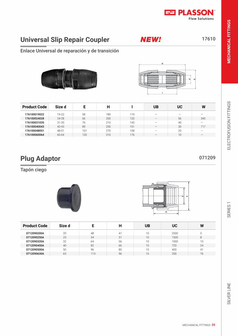
Universal Slip Repair Coupler NEW! 17610
Enlace Universal de reparación y de transición
Ed
l
H
Product Code Size d E H l UB UC W
176100019022 19-22 58 180 119 — — —176100024028 24-28 66 200 133 — 56 345176100031035 31-35 76 210 143 — 40 —176100040043 40-43 89 250 151 — 30 717176100048051 48-51 101 270 158 — 20 —176100060064 60-64 120 310 176 — 10 —
Plug Adaptor 071209
Tapón ciego
Ed
H
Product Code Size d E H UB UC W
0712090200A 20 48 47 10 2500 50712090250A 25 54 51 10 1500 80712090320A 32 64 56 10 1000 150712090400A 40 82 66 10 720 240712090500A 50 96 80 10 400 410712090630A 63 113 96 10 200 76

40 MECHANICAL FITTINGS
Technical catalogue 2019 | Conversion & Adaptor Sets
Pipe Liner for PE SDR 11 Pipe 07950
Refuerzo de tubos
d
H
Product Code Size d* H UB UC W
079500020 20 x 2.3 63 10 2520 5079500025 25 x 2.3 63 10 1680 10079500032 32 x 3.0 79 10 920 13079500040 40 x 3.7 97 10 480 25079500050 50 x 4.6 106 10 240 45079500063 63 x 5.8 125 5 110 72
* O.D. of pipe x wall thickness of pipe | * Diametro externo del tubo x espesor del tubo
Adaptor for Copper and Imperial UPVC 07896*
Adaptador para cobre y PVCU
Ed1d
I
Product Code Size d x d1 E I UB UC W
07896015P 20 x 15 48 66 25 1500 1507896022P 25 x 22 54 64 20 1200 1507896028P 32 x 28 64 74 20 700 2707896035P 40 x 35 82 92 10 240 5407896042P 50 x 42 96 105 10 160 111
* No Pull-Out Resistance | * Sin resistencia a la tracción

41MECHANICAL FITTINGS
MEC
HA
NIC
AL
FITT
ING
SEL
ECTR
OFU
SIO
N F
ITTI
NG
SSE
RIES
1SI
LVER
LIN
E
Reducing Set 07930
Juego reductor
Ed1d
I
Product Code Size d x d1 E I UB UC W
0793000250200A 25 x 20 54 56 — 300 220793000320200A 32 x 20 64 62 — 300 380793000320250A 32 x 25 64 60 — 250 350793000400200A 40 x 20 82 73 — 180 620793000400250A 40 x 25 82 69 — 180 810793000400320A 40 x 32 82 77 — 200 620793000500250A 50 x 25 96 85 — 120 1140793000500320A 50 x 32 96 87 — 120 1120793000500400A 50 x 40 96 85 — 120 970793000630250A 63 x 25 113 103 — 80 2170793000630320A 63 x 32 113 102 — 80 2140793000630400A 63 x 40 113 103 — 80 2010793000630500A 63 x 50 113 105 — 80 1870793001100630A 75 x 63 132 121 1 70 2200793001100630A 110 x 63* 181 131 — 24 7030793001100630A 110 x 75* 181 145 1 25 6550793001100630A 110 x 90* 181 154 1 20 671
* Reducer made of polypropylene | * Reductor de pp
Split Ring for UPVC and PP pipes 07003Q
Product Code Size d UB UC W
07003Q0075P 75 — — —07003Q0030P 90 1 — —07003Q0110P 110 1 — —07003Q0125P 125 — — —

42 MECHANICAL FITTINGS
Technical catalogue 2019 | Conversion & Adaptor Sets
Modular Adaptor 07940
Adaptador modulado
E d
H
I
Product Code Size d E H I UB UC W
0794060200A 20 48 80 10 — 300 500794060250A 25 54 80 10 — 250 610794060320A 32 64 93 10 — 180 1040794060400A 40 82 102 10 — 100 1730794060500A 50 93 107 10 5 70 2570794060630A 63 113 119 10 5 45 422
Copper Pipe Adaptor 0701C6
Adaptador para tubo de cobre
H
I1I
d d1E E1
Product Code Size d (PE) x d1 (Cu) E E1 H I I1 UB UC W
0701C6020015 20 x 15 48 39 115 56 54 — 200 1030701C6020015 25 x 15 54 39 124 55 54 — 180 860701C6025022 25 x 22 54 54 136 60 71 — 150 1320701C0032028 32 x 28 64 64 150 70 77 — 100 199
Grip Ring for UPVC and PP pipe 07970
Casquillo de apriete para tubos de UPVC y PP
d
Product Code Size d UB UC W
07970020 20 — 10000 107970025 25 — 10000 207970032 32 — 10000 307970040 40 — 1000 607970050 50 — 1000 1007970063 63 — 1000 17

43MECHANICAL FITTINGS
MEC
HA
NIC
AL
FITT
ING
SEL
ECTR
OFU
SIO
N F
ITTI
NG
SSE
RIES
1SI
LVER
LIN
E
Conversion Set for Copper Pipe 074380
Juego adaptador para tubos de cobre
Ed1d
I
Product Code Size d x d1 E I UB UC W
07438015 20 x 15 48 67 10 360 2007438016 25 x 15 54 69 10 360 2907438022 25 x 22 54 67 10 360 2507438028 32 x 28 64 77 10 300 2707438035 40 x 35 82 92 10 300 3807438042 50 x 42 96 105 10 250 6407438054 63 x 54 113 121 1 150 102
Conversion Set for CTS dimensions Copper PipeDimensiones CTS
Product Code Size d x d1 E I UB UC W
07439204 20 x 1/2” (O.D. 15.8mm) 48 67 10 600 2007438022 25 x 3/4” (O.D. 22.2mm) 54 69 10 500 33
Conversion Set for Australian dimensions Copper Pipe (AS 1432)Dimensiones Australianas (AS 1432)
Product Code Size d x d1 E I UB UC W
07439205 20 x 15 (1/2”) (O.D. 12.7mm) 48 67 1 300 4207439257 25 x 20 (3/4”) (O.D. 19.5mm) 54 69 1 250 5107439251 25 x 25 (1”) (O.D. 25.4mm) 54 69 1 250 34
Coupling for PVC Pipe 0701QQ
Enlace recto para tubo de PVC
H
dE
II
Product Code Size d x d E H I UB UC W
0701QQ075 75 x 75 134 278 138 — 16 11830701QQ090 90 x 90 154 335 165 — 10 18980701QQ110 110 x 110 181 393 194 — 5 31290701QQ125 125 x 125 212 460 225 — 3 5347

44 MECHANICAL FITTINGS
Technical catalogue 2019 | Conversion & Adaptor Sets
Conversion Set for Lead Pipe 077802
Juego adaptador para tubos de plomo
d
I
d1 E
Product Code Size d x d1 E I UB UC W
077802025003 25 x 3/8” 5 LB 54 67 5 1000 15077802025005 25 x 1/2” 7 LB 54 64 5 1500 8077802032005 32 x 1/2” 9 LB 64 77 5 500 24077802032007 32 x 3/4” 9 LB 64 76 5 1000 13077802040007 40 x 3/4” 11 LB 82 95 5 400 42077802050010 50 x 1” 16 LB 96 104 5 250 68
Converter Rubber Adaptor for Galvanised Pipe 078908*
Conversor de goma para tubos de acero galvanizado
d
Id1 E
Product Code Size d x d1 E I UB UC W
078908010 40 x 1” 82 89 5 200 60078908013 50 x 1 1/4” 96 98 5 150 89078908015 50 x 1 1/2” 96 90 5 150 35078908020 63 x 2” 113 108 5 120 71
* Without pullout resistance | * Extraccion sin resistencia

45MECHANICAL FITTINGS
MEC
HA
NIC
AL
FITT
ING
SEL
ECTR
OFU
SIO
N F
ITTI
NG
SSE
RIES
1SI
LVER
LIN
E
Conversion Set Adaptor for Galvanised Pipe 078907
Juego de conversion para tubos de acero galvanizado
d
I
d1 E
Product Code Size d x d1 E I UB UC W
078907010 40 x 1” 82 96 5 200 117078907013 50 x 1 1/4” 96 105 5 150 150078907015 50 x 1 1/2” 96 115 5 150 125078907020 63 x 2” 113 117 5 100 226

46 ELECTROFUSION FITTINGS
The basic fitting is a dedicated product for joining metric PE pipe. It will securely join the pipe without any additional components. The fittings can be easily converted for use with other materials simply by adding a conversion set. Plasson offers a full range of conversion sets to provide exceptional adaptability.
El accesorio básico es un producto dedicado a conectar tuberías de PE sin componentes adicionales, con la máxima seguridad. Los accesorios se pueden ser convertidos facilmente a cualquier tipo de tubería usando un juego de conversión. Plasson ofrece una gama que permite una adaptabilidad excepcional.
Copper (without pullout resistance)Cobre (sin resistencia a tracción)
Imperial U-PVC (without pullout resistance)U-PVC imperial (sin resistencia a tracción)
Galvanised steelAcero galvanizado
Lead pipePlomo
CopperCobre
Galvanised steel (without pullout resistance)Acero galvanizado (sin resistencia a tracción)
Metric PEPE métrico
Metric U-PVC & PPPVC - U y PP métrico
P i p e C o n v e r s i o n C h a r tMetric PE / Metric U-PVC / Metric PP / Galvanised Steel / Lead Pipe / Imperial U-PVC/Copper
PE métrico / PP y PVCU métrico / Acero galvanizado / Plomo / U-PVC imperial / Cobre...

47MECHANICAL FITTINGS
MEC
HA
NIC
AL
FITT
ING
SEL
ECTR
OFU
SIO
N F
ITTI
NG
SSE
RIES
1SI
LVER
LIN
E
Nut 07004
Racor
H
E d
I2
Product Code Size d x d1 E H I2 UB UC W
070046016P 16 39 40 23 — 1000 12070046020P 20 48 45 26 — 700 22070046025P 25 54 46 26 — 500 26070046032P 32 64 51 30 — 300 41070046040P 40 82 63 34 — 200 70070046050P 50 96 71 34 5 125 104070046063P 63 113 89 43 5 100 172070046075P 75 132 110 56 — 64 279070046090P 90 152 135 73 — 36 435070046110P 110 181 170 97 — 16 752070046125P 125 212 185 107 — 10 1135
O - Ring NBR 07002
Junta tórica (NBR)
E1
e
Product Code Size d E1 e UB UC W
070020016 16 15 3 — — —070020020 20 19 3 — — —070020025 25 24 4 — — —070020032 32 31 5 — — —070020040* 40 — — — — —070020050* 50 — — — — —070020063* 63 — — — — —070020075 75 74 8 — 1600 16070020090 90 89 8 — 1500 17070020110 110 108 9 — 900 27070020125 125 122 10 — — —
* Only for slip repair coupling and tee

48 MECHANICAL FITTINGS
Technical catalogue 2019 | Accessories for Compression Fittings
O - Ring EPDM (Blue Mark) 07002D0
Junta tórica EPDM, (marca azul)
Product Code Size d E1 e UB UC W
07002D016 16 15 3 100 30000 107002D020 20 19 3 100 16000 107002D025 25 24 4 100 16000 107002D032 32 31 5 100 8000 207002D040* 40 — — 20 4000 407002D050* 50 — — 20 2500 707002D063* 63 — — 20 2000 807002D075 75 74 8 10 1600 1607002D090 90 89 8 10 1400 1707002D110 110 108 9 10 900 27070020125 — — — — — —
* Only for slip repair coupling and tee
O - Ring Viton FPM (White Mark) 07002V0
Junta tórica FPM, (marca blanca)
Product Code Size d E1 e UB UC W
03050905 16 15 3 — — 207002V020 20 19 3 — 32000 207002V025 25 24 4 — 16000 207002V032 32 31 5 — 8000 407002V040* 40 39 6 — 4000 707002V050* 50 49 7 — 2500 1207002V063* 63 62 7 — 2000 1507002V075 75 74 8 — 1600 2307002V090 90 89 8 — 1400 2807002V110 110 108 9 — 900 43
* Only for slip repair coupling and tee
Seal - NBR 070029
Sello de NBR
E1
e
Product Code Size d E1 e UB UC W
070029040 40 38 8 50 2600 4070029050 50 49 9 50 1600 8070029063 63 62 9 50 1500 9

49MECHANICAL FITTINGS
MEC
HA
NIC
AL
FITT
ING
SEL
ECTR
OFU
SIO
N F
ITTI
NG
SSE
RIES
1SI
LVER
LIN
E
Seal EPDM (Blue Mark) 07002D9
Sello EPDM, (marca azul)
Product Code Size d E1 e UB UC W
07002D940 40 38 8 20 4000 407002D950 50 49 9 20 2500 707002D963 63 62 9 20 2000 9
Seal Viton FPM (White Mark) 07002V9
Sello de Viton FPM, (marca blanca)
Product Code Size d E1 e UB UC W
07002V940 40 38 8 — 4000 707002V950 50 49 9 — 2500 1207002V963 63 62 9 — 2000 14
Split Ring - Polyacetal 07003
Casquillo de apriete (acetal)
E d
H
Product Code Size d E H UB UC W
070030016P 16 23 12 — 12000 1070030020P 20 31 13 — 6500 3070030025P 25 36 13 — 4500 4070030032P 32 44 19 — 2000 7070030040P 40 55 24 — 1200 12070030050P 50 67 30 — 500 24070030063P 63 83 37 — 300 46070030065P 65.8 — — — 300 46070030075P 75 96 8 — 200 48070030090P 90 115 8 — 115 111070030110P 110 135 8 — 70 151070030125P 125 161 8 — 35 291

50 MECHANICAL FITTINGS
Technical catalogue 2019 | Accessories for Compression Fittings
Split Ring - CPVC 07003V
Casquilla de apriete (CPVC)
E d
H
Product Code Size d E H UB UC W
07003V016P 16 23 12 — 12000 307003V020P 20 31 13 — 6500 407003V025P 25 36 13 — 4500 507003V032P 32 44 19 — 1500 1107003V040P 40 55 24 — 1200 1907003V050P 50 67 30 — 500 3207003V063P 63 83 37 — 300 5307003V075P 75 96 37 — 200 7107003V090P 90 115 56 — 100 12607003V110P 110 135 56 — 70 150
Insert 07005
Inserto de PP
d D
H
Product Code Size d D H UB UC W
070050016P 16 17 12 — 8700 1070050020P 20 — — — 5000 1070050025P 25 — — — 4000 3070050032P 32 — — — 4000 6070050075P 75 94 23 — 300 31070050090P 90 116 32 — 160 56070050110P 110 138 36 — 100 81070050125P 125 Upper 164 48 — 80 153070051125P 125 Lower 142 18 — 160 204

51MECHANICAL FITTINGS
MEC
HA
NIC
AL
FITT
ING
SEL
ECTR
OFU
SIO
N F
ITTI
NG
SSE
RIES
1SI
LVER
LIN
E
Chamfer Tool for PE Pipes 18960
Herramienta para biselar
Product Code Size UB UC W
189600063020P 20 - 63 — 64 202
Plasson Wrench 07990
Llave Plasson
Product Code Size UB UC W
07990001 16 - 40 — 250 6507990005 40 - 75 — 75 29607990000 63 - 125 — 40 840

52 MECHANICAL FITTINGS
Technical catalogue 2019 | Fittings for 160mm Pipes
Coupling 070106
Racor
Ed
IIH
Product Code Size d x d E I H UB UC W
0701061600A 160 x 160 280 204 418 — 2 8888
Repair Coupling 076106
Enlace recto de reparación
Ed
IIH
Product Code Size d x d E I H UB UC W
0761061600A 160 x 160 280 — 418 — 2 8838

53MECHANICAL FITTINGS
MEC
HA
NIC
AL
FITT
ING
SEL
ECTR
OFU
SIO
N F
ITTI
NG
SSE
RIES
1SI
LVER
LIN
E
90º Tee 070406
Te de 90°
IA
II H
dE
Product Code Size d x d x d E I H A UB UC W
0704061600A 160 x 160 x 160 280 204 601 301 — 1 14660
90º Elbow 070506
Codo de 90°
Ed
IA
Product Code Size d x d E I A UB UC W
0705061600A 160 x 160 280 204 301 — 2 10028

54 MECHANICAL FITTINGS
Technical catalogue 2019 | Fittings for 160mm Pipes
Compression Flange Adaptor (with Metal Flange) 072206
Adaptador compresión-brida (con brida de metal)
H
D Dp
S
Ed
I
Product Code Size d x DN (inch) E H I D Dp S No. of Holes Metal-Flange Size UC W
0722061600500A 160 x 125 (5”) 280 304 204 250 210 18 8 125 / 160 x 125 3 77810722061600600A 160 x 150 (6”) 280 304 204 285 240 22 8 125 / 160 x 150 3 9188
Flange Adaptor (with Metal Flange) 072306
Adaptador brida (con brida de metal)
H
D Dp
S
d
Product Code Size d x DN (inch) H D Dp S No. of Holes Metal-Flange Size UC W
0723061600500A 160 x 125 (5”) 265 250 210 18 8 125 / 160 x 125 6 44090723061600600A 160 x 150 (6”) 265 285 240 22 8 125 / 160 x 150 5 5886

55MECHANICAL FITTINGS
MEC
HA
NIC
AL
FITT
ING
SEL
ECTR
OFU
SIO
N F
ITTI
NG
SSE
RIES
1SI
LVER
LIN
E
Shouldered Adaptor 073206
Adaptador minero
HI L
BdE
Product Code Size d x DN (inch) E H I L B UB UC W
0732061600600A 160 x 150 (6”) 280 304 204 18 175 — 4 5170
Half Metal Flange 070060160
Brida de metal
D
t
S D1Dp
Product Code Size d x DN (inch) D Dp D1 S t Th* (mm) Th* (inch) No. of Holes W
070060160050P 125 / 160 x 125 (5”) 250 210 170 18 12 M16 5/8 8 1100070060160060P 125 / 160 x 150 (6”) 250 240 170 22 12 M20 3/4 8 1800
* Nominal diameter of bolts | * Diametro nominal del tornillo

56 MECHANICAL FITTINGS
Technical catalogue 2019 | Threaded and Compression Outlet Saddles
Saddle Single Outlet with Reinforcing Ring Options 16076
Collarin simple con anillo de refuerzo 16086 - For saddle without reinforcing ring. For more details, see table on page 76, 77
BRp
L L1
A
d
Product Code Size d x Rp B L L1 A No. of Bolts UB UC W
160760020005 20 x 1/2" 10 70 45 33 2 — 400 63160760025005 25 x 1/2" 15 75 50 36 2 — 300 70160760025007 25 x 3/4" 15 75 50 37 2 — 300 73160760032005 32 x 1/2" 16 92 60 40 2 — 150 133160760032007 32 x 3/4" 19 92 60 41 2 — 150 135160760032010 32 x 1" 20 92 60 42 2 — 150 142160760040005 40 x 1/2" 16 92 60 45 2 — 150 141160760040007 40 x 3/4" 19 92 60 46 2 — 150 143160760040010 40 x 1" 25 92 60 49 2 — 150 151160760050005 50 x 1/2" 16 106 73 51 2 — 100 179160760050007 50 x 3/4" 21 106 73 52 2 — 100 180160760050010 50 x 1" 25 106 73 54 2 — 100 187160760050013 50 x 1 1/4" 25 106 73 58 2 — 100 212160760063005 63 x 1/2" 16 116 84 58 4 — 70 278160760063007 63 x 3/4" 20 116 84 59 4 — 70 279160760063010 63 x 1" 25 116 84 61 4 — 70 286160760063013 63 x 1 1/4" 32 116 84 66 4 — 70 308160760063015 63 x 1 1/2" 39 116 84 67 4 — 60 322160760075005 75 x 1/2" 16 122 98 64 4 — 60 369160760075007 75 x 3/4" 20 122 98 65 4 — 55 369160760075010 75 x 1" 25 122 98 67 4 — 55 376160760075013 75 x 1 1/4" 32 122 98 72 4 — 55 398160760075015 75 x 1 1/2" 40 122 98 73 4 — 50 411160760075020 75 x 2" 40 122 98 78 4 — 50 433160760090005 90 x 1/2" 16 141 105 72 4 — 45 453160760090007 90 x 3/4" 20 141 105 73 4 — 45 454160760090010 90 x 1" 25 141 105 75 4 — 45 460160760090013 90 x 1 1/4" 32 141 105 80 4 — 40 483160760090015 90 x 1 1/2" 40 141 105 81 4 — 40 467160760090020 90 x 2" 50 141 105 86 4 — 40 511160760110005 110 x 1/2" 16 165 116 83 4 — 45 561160760110007 110 x 3/4" 20 165 116 84 4 — 45 562160760110010 110 x 1" 25 165 116 87 4 — 36 567160760110013 110 x 1 1/4" 32 165 116 91 4 — 36 588160760110015 110 x 1 1/2" 40 165 116 92 4 — 36 600160760110020 110 x 2" 50 165 116 97 4 — 30 615160760125007 125 x 3/4" 20 184 124 91 6 — 30 749160760125010 125 x 1" 25 184 124 94 6 — 30 755160760125013 125 x 1 1/4" 32 184 124 98 6 — 30 778160760125015 125 x 1 1/2" 40 184 124 99 6 — 30 781160760125020 125 x 2" 50 184 124 104 6 — 25 796160760140010 140 x 1" 25 201 136 101 6 — 24 893160760140013 140 x 1 1/4" 32 201 136 106 6 — 24 912160760140015 140 x 1 1/2" 40 201 136 107 6 — 24 922160760140020 140 x 2" 50 201 136 112 6 — 20 938160760160010 160 x 1" 25 223 145 112 6 — 20 1039160760160013 160 x 1 1/4" 32 223 145 117 6 — 20 1061160760160015 160 x 1 1/2" 40 223 145 118 6 — 20 1071160760160020 160 x 2" 50 223 145 123 6 — 20 1080160760180010 180 x 1" 25 245 154 122 6 — 16 1300160760180013 180 x 1 1/4" 32 245 154 127 6 — 16 1319160760180015 180 x 1 1/2" 40 245 154 128 6 — 16 1349160760180020 180 x 2" 50 245 154 133 6 — 16 1334
* With coated steel bolts, Stainless steel bolts – optional

57MECHANICAL FITTINGS
MEC
HA
NIC
AL
FITT
ING
SEL
ECTR
OFU
SIO
N F
ITTI
NG
SSE
RIES
1SI
LVER
LIN
E
Saddle Double Outlet with Reinforcing Ring Options 16176
Collarin doble con anillo de refuerzo 16186 - For saddle without reinforcing ring. For more details, see table on page 76, 77
BRp
L L1
A (x
2)
d
Product Code Size d x Rp B L L1 A No. of Bolts UB UC W
161760020005 20 x 1/2" 10 70 45 66 2 — 300 73161760025005 25 x 1/2" 15 75 50 71 2 — 250 81161760025007 25 x 3/4" 15 75 50 73 2 — 250 86161760032005 32 x 1/2" 16 92 60 80 2 — 140 144161760032007 32 x 3/4" 19 92 60 82 2 — 140 148161760032010 32 x 1" 20 92 60 84 2 — 140 163161760040005 40 x 1/2" 16 92 60 89 2 — 120 153161760040007 40 x 3/4" 19 92 60 91 2 — 120 157161760040010 40 x 1" 25 92 60 98 2 — 120 174161760050005 50 x 1/2" 16 106 73 102 2 — 80 193161760050007 50 x 3/4" 21 106 73 104 2 — 80 196161760050010 50 x 1" 25 106 73 109 2 — 80 210161760050013 50 x 1 1/4" 25 106 73 117 2 — 80 260161760063005 63 x 1/2" 16 116 84 116 4 — 80 293161760063007 63 x 3/4" 20 116 84 118 4 — 80 296161760063010 63 x 1" 25 116 84 123 4 — 70 310161760063013 63 x 1 1/4" 32 116 84 132 4 — 70 354161760063015 63 x 1 1/2" 39 116 84 133 4 — 60 382161760075005 75 x 1/2" 16 122 98 128 4 — 60 382161760075007 75 x 3/4" 20 122 98 130 4 — 60 382161760075010 75 x 1" 25 122 98 135 4 — 50 397161760075013 75 x 1 1/4" 32 122 98 144 4 — 50 438161760075015 75 x 1 1/2" 40 122 98 145 4 — 50 465161760075020 75 x 2" 40 122 98 155 4 — 40 513161760090005 90 x 1/2" 16 141 105 143 4 — 45 467161760090007 90 x 3/4" 20 141 105 146 4 — 45 468161760090010 90 x 1" 25 141 105 151 4 — 45 482161760090013 90 x 1 1/4" 32 141 105 160 4 — 40 526161760090015 90 x 1 1/2" 40 141 105 162 4 — 40 546161760090020 90 x 2" 50 141 105 172 4 — 36 585161760110005 110 x 1/2" 16 165 116 166 4 — 40 575161760110007 110 x 3/4" 20 165 116 168 4 — 40 577161760110010 110 x 1" 25 165 116 173 4 — 36 586161760110013 110 x 1 1/4" 32 165 116 182 4 — 30 628161760110015 110 x 1 1/2" 40 165 116 187 4 — 30 653161760110020 110 x 2" 50 165 116 196 4 — 24 685161760125007 125 x 3/4" 20 184 124 182 6 — 20 814161760125010 125 x 1" 25 184 124 187 6 — 20 814161760125013 125 x 1 1/4" 32 184 124 196 6 — 20 814161760125015 125 x 1 1/2" 40 184 124 198 6 — 20 834161760125020 125 x 2" 50 184 124 208 6 — 20 861161760140010 140 x 1" 25 201 136 202 6 — 20 948161760140013 140 x 1 1/4" 32 201 136 212 6 — 20 947161760140015 140 x 1 1/2" 40 201 136 213 6 — 20 967161760140020 140 x 2" 50 201 136 223 6 — 20 1001161760160010 160 x 1" 25 223 145 223 6 — 16 1055161760160013 160 x 1 1/4" 32 223 145 233 6 — 16 1098161760160015 160 x 1 1/2" 40 223 145 235 6 — 16 1119161760160020 160 x 2" 50 223 145 245 6 — 16 1137161760180010 180 x 1" 25 245 154 243 6 — 16 1310161760180013 180 x 1 1/4" 32 245 154 253 6 — 16 1335161760180015 180 x 1 1/2" 40 245 154 255 6 — 16 1247161760180020 180 x 2" 50 245 154 265 6 — 16 1368
* With coated steel bolts, Stainless steel bolts – optional

58 MECHANICAL FITTINGS
Technical catalogue 2019 | Tapping Saddles & Valves
Mechanical Tapping Valve 18680
Valvula mecanica con salida rotatoria tapper
L
H
d1H
1
H2
E
d
Product Code Size d x D1 L L1* H H1 H2 E I UB UC W
186800063032 63 x 32 116 55 135 240 55 64 67 — 8 2090186800063063 63 x 63 116 60 200 240 60 113 110 — 8 2210186800075032 75 x 32 122 60 135 244 60 64 67 — 8 1840186800075063 75 x 63 122 65 200 244 65 113 110 — 8 2230186800090032 90 x 32 141 60 135 244 60 64 67 — 8 2150186800090063 90 x 63 141 65 200 244 65 113 110 — 8 2270186800110032 110 x 32 165 60 135 244 60 64 67 — 8 2270186800110063 110 x 63 165 65 200 244 65 113 110 — 8 2730186800125032 125 x 32 184 60 135 244 60 64 67 — 8 2280186800125063 125 x 63 184 65 200 244 65 113 110 — 8 2390186800140032 140 x 32 201 60 135 244 60 64 67 — 8 2290186800140063 140 x 63 201 65 200 244 65 113 110 — 6 2440186800160032 160 x 32 223 60 135 244 60 64 67 — 6 2490186800160063 160 x 63 223 65 200 244 65 113 110 — 6 2440186800180032 180 x 32 245 60 135 244 60 64 67 — 6 2550186800180063 180 x 63 245 65 200 244 65 113 110 — 4 2550
* L1 - Length along pipe | * L1 - longueur de la prise de branchement* With stainless steel bolts and nuts

59MECHANICAL FITTINGS
MEC
HA
NIC
AL
FITT
ING
SEL
ECTR
OFU
SIO
N F
ITTI
NG
SSE
RIES
1SI
LVER
LIN
E
Tapper - for PVC & PE Pipes 16540
Collarin con salida rotatoria Tapper® para tubos de PVC y de PE
d
H
H2
H1
d1
L
Product Code Size D x Dn H L L1* H1 H2 No. of Bolts UB UC W
165409063025 63 x 25 105 116 84 57 130 4 1 40 584165409063032 63 x 32 109 116 84 57 130 4 1 40 630165409075025 75 x 25 109 122 98 57 130 4 1 30 700165409075032 75 x 32 105 141 105 58 131 4 1 30 750165409090025 90 x 25 109 141 105 58 131 4 1 25 761165409090032 90 x 32 105 165 116 59 132 4 1 25 780165409110025 110 x 25 109 165 116 59 132 4 1 20 875165409110032 110 x 32 105 184 124 58 131 6 1 20 915165409125025 125 x 25 109 184 124 58 131 6 1 16 1080165409125032 125 x 32 105 201 136 59 132 6 1 16 1110165409140025 140 x 25 109 201 136 59 132 6 1 14 1228165409140032 140 x 32 105 223 145 59 132 6 1 14 1228165409160025 160 x 25 109 223 145 59 132 6 1 10 1370165409160032 160 x 32 105 245 154 60 133 6 1 10 1400165409177025 177 x 25 109 245 154 60 133 6 1 8 1618165409177032 177 x 32 — — — — — 6 1 8 1639165409180025 180 x 25 106 245 — 60 133 6 1 8 1812165409180032 180 x 32 111 245 — 60 133 6 1 8 1400
* L1 - Length along pipe | * L1 - longueur de la prise de branchement* With stainless steel bolts and nuts

60 MECHANICAL FITTINGS
Technical catalogue 2019 | BSP Threaded Fittings
Threaded Socket 050107*
Manguito rosca hembra x hembra
Rp RpE
I2I2
H
Product Code Size Rp x Rp H I2 E UB UC W
050107005 1/2” x 1/2” 39 17 30 10 1200 15050107007 3/4” x 3/4” 41 19 36 10 1000 19050107010 1” x 1” 45 21 46 10 600 31050107013 1 1/4” x 1 1/4” 54 25 60 10 250 65050107015 1 1/2” x 1 1/2” 54 25 65 10 250 76050107020 2” x 2” 66 31 75 5 150 92
* With reinforcing ring - Cat. No. 050117 | * Con anillo de refuerzo - Cat. No. 050117
Threaded Reducing Bushing 050207
Manguito reductor hembra x macho
Rp Rp1 E
I2
H
Product Code Size Rp x Rp1 H I2 E UB UC W
050207007005 3/4” x 1/2” 30 17 27 10 2000 6050207010005 1” x 1/2” 32 19 36 10 1200 16050207010007 1” x 3/4” 32 19 36 10 1000 11050207013005 1 1/4” x 1/2” 37 21 46 10 700 27050207013007 1 1/4” x 3/4” 37 21 46 10 700 28050207013010 1 1/4” x 1” 37 21 46 10 700 21050207015010 1 1/2” x 1” 37 21 50 10 500 32050207015013 1 1/2” x 1 1/4” 37 21 50 10 500 20050207020005 2” x 1/2” 41 25 63 5 350 60050207020007 2” x 3/4” 41 25 63 5 350 58050207020010 2” x 1” 41 26 63 5 300 61050207020013 2” x 1 1/4” 41 26 63 5 320 55050207020015 2” x 1 1/2” 41 26 63 5 320 44050207025020 2 1/2” x 2” 44 29 80 5 200 75050207030010 3” x 1” 48 32 90 2 150 117050207030013 3” x 1 1/4” 48 32 90 2 150 119050207030015 3” x 1 1/2” 48 32 90 2 150 118050207030020 3” x 2” 48 32 90 2 100 103050207030025 3” x 2 1/2” 48 32 90 2 150 75050207040020 4” x 2” 56 41 120 2 80 238050207040030 4” x 3” 56 41 120 2 80 222

61MECHANICAL FITTINGS
MEC
HA
NIC
AL
FITT
ING
SEL
ECTR
OFU
SIO
N F
ITTI
NG
SSE
RIES
1SI
LVER
LIN
E
90º Threaded Tee 050407*
Te de 90° rosca hembra
I2
RpRp
HI2
Rp
I2
Product Code Size Rp H I2 UB UC W
050407005 1/2” 64 18 10 700 28050407007 3/4” 68 19 10 500 39050407010 1” 81 21 10 260 61050407013 1 1/4” 96 25 5 140 114050407015 1 1/2” 108 25 5 90 157050407020 2” 130 30 5 60 205
* With reinforcing ring - Cat. No. 050417 | * Con anillo de refuerzo - Cat. No. 050417
90º Threaded Elbow 050507*
Codo de 90° rosca hembra
I2
Rp
A
I2Rp
Product Code Size Rp x Rp A I2 UB UC W
050507005 1/2” x 1/2” 32 17 10 1000 22050507007 3/4” x 3/4” 35 18 10 700 30050507010 1” x 1” 41 21 10 400 45050507013 1 1/4” x 1 1/4” 48 25 10 200 87050507015 1 1/2” x 1 1/2” 54 25 5 150 116050507020 2” x 2” 65 30 5 80 157
* With reinforcing ring - Cat. No. 050517 | * Con anillo de refuerzo - Cat. No. 050517

62 MECHANICAL FITTINGS
Technical catalogue 2019 | BSP Threaded Fittings
90º Threaded Elbow Male x Female 051507
Codo roscado-macho x hembraR
Rp
A
I
I1
A1
Product Code Size R x Rp A A1 I I1 UB UC W
051507005 1/2” x 1/2” 36 36 16 17 10 1000 17051507007 3/4” x 3/4” 40 40 17 18 10 700 25051507010 1” x 1” 45 47 19 21 10 400 40
Threaded Reducing Nipple 050605
Machón doble reductor
RE R
I1I
H
Product Code Size R x R A A1 I I1 UB UC W
050605007005 3/4” x 1/2” 47 17 17 16 10 1500 10050605010005 1” x 1/2” 49 19 19 16 10 800 17050605010007 1” x 3/4” 50 19 19 17 10 800 18050605013005 1 1/4” x 1/2” 53 21 21 16 10 500 28050605013007 1 1/4” x 3/4” 54 21 21 17 10 500 29050605013010 1 1/4” x 1” 56 21 21 19 10 500 31050605015005 1 1/2” x 1/2” 54 21 21 16 5 500 34050605015007 1 1/2” x 3/4” 55 21 21 17 5 500 34050605015010 1 1/2” x 1” 57 21 21 19 5 400 36050605015013 1 1/2” x 1 1/4” 59 21 21 21 5 400 39050605020005 2” x 1/2” 58 25 25 16 5 280 51050605020007 2” x 3/4” 59 25 25 17 5 260 52050605020010 2” x 1” 61 25 25 19 5 260 53050605020013 2” x 1 1/4” 63 25 25 21 5 240 57050605020015 2” x 1 1/2” 63 25 25 21 5 240 58

63MECHANICAL FITTINGS
MEC
HA
NIC
AL
FITT
ING
SEL
ECTR
OFU
SIO
N F
ITTI
NG
SSE
RIES
1SI
LVER
LIN
E
Threaded Nipple 050607
Machón doble
RE
I2
H
Product Code Size R x R H I2 E UB UC W
050607005 1/2” x 1/2” 47 17 22 10 2000 8050607007 3/4” x 3/4” 49 18 27 10 1500 11050607010 1” x 1” 55 20 36 10 800 23050607013 1 1/4” x 1 1/4” 60 22 46 10 400 35050607015 1 1/2” x 1 1/2” 61 22 50 5 300 48050607020 2” x 2” 71 26 65 5 180 78
Threaded Cap 050707
Machón doble
RpE
I2
H
Product Code Size Rp E H I2 UB UC W
050707005 1/2” 37 25 15 10 1600 13050707007 3/4” 42 26 16 10 1500 14050707010 1” 50 32 19 10 800 27050707013 1 1/4” 59 34 22 10 500 39050707015 1 1/2” 65 34 21 10 450 43050707020 2” 80 39 25 5 250 78

64 MECHANICAL FITTINGS
Technical catalogue 2019 | BSP Threaded Fittings
Threaded Reducing Socket 051107
Manguito reductor rosca hembra - hembra
Rp1
RpE
I1I
H
Product Code Size Rp x Rp1 H I I1 E UB UC W
051107007005 3/4” x 1/2” 50 20 19 36 10 800 25
Threaded Riser 051607
Espiga roscada
RR E
I2I2
H
Product Code Size R x R H I2 E UB UC W
051607005 1/2” x 1/2” 150 17 22 10 600 30051607007005 3/4” x 1/2” 113 18 27 10 500 26051607007 3/4” x 3/4” 150 18 27 10 400 43051607010 1” x 1” 150 19 36 5 250 65051607013 1 1/4” x 1 1/4” 150 21 46 5 150 93051607015013 1 1/2” x 1 1/4” 150 21 50 5 140 115051607015 1 1/2” x 1 1/2” 150 21 50 5 140 120

65MECHANICAL FITTINGS
MEC
HA
NIC
AL
FITT
ING
SEL
ECTR
OFU
SIO
N F
ITTI
NG
SSE
RIES
1SI
LVER
LIN
E
Threaded Plug 051707
Tapón rosca macho
R E
I2
H
Product Code Size R H I2 E UB UC W
051707003 3/8” 24 13 22 10 4500 4051707005 1/2” 29 16 27 10 2500 8051707007 3/4” 31 17 32 10 1500 12051707010 1” 34 19 36 10 1000 16051707013 1 1/4” 38 21 46 10 700 26051707015 1 1/2” 39 21 55 10 500 38051707020 2” 45 25 65 10 300 60

66
BALL VALVE 03703FULL BORE BALL VALVE
WITH A DRAIN PORT OPTION!
• Full bore design minimizing pressure loss
• Various drainage options
• Rated PN16/231 PSI
• Glass Reinforced Polyamide body
FEATURES AND BENEFITS
* Optional drain ports ISO 7-1 Rp thread
E-mail: [email protected] www.plasson.com
REMOVABLE TAMPER RESISTANT HANDLE
Easily identifiable drain port option:• Blue dot - no drain port• Black plug- optional drain port
PLASSON'S BALL VALVE is produced entirely of plastic, eliminating the risk of corrosive damage to the system
PLASSON'S BALL VALVE features an option for two drain ports or no drain ports. Ideally suited for draining or sampling of potable water systems and monitoring system pressure,Plasson's valves allow simple and direct connections to hoses without tampering with the system line.
TWO DRAIN PORT OPTION

MECHANICAL FITTINGS
MEC
HA
NIC
AL
FITT
ING
SEL
ECTR
OFU
SIO
N F
ITTI
NG
SSE
RIES
1SI
LVER
LIN
E
67
Ball Valve NEW! 03703
Válvula esférica
RcDN
A2
A1
HI B
E
Product Code Size Rc H E l B A1 A2 DN UC W
0370300007 3/4” 97 53 18 36 27 54 20 10 45000370300010 1” 116 64 21 46 33 64 25 10 45000370300013 1 1/4” 118 73 20 55 36 70 32 10 45000370300015 1 1/2” 144 91 24 65 45 87 40 10 45000370300020 2” 162 100 29 75 53 97 50 10 4500
* 037030F - with drain port
Threaded Stoptap (Seal NBR) 03405
Válvula de línea rosca hembra (juntas NBR)
H
A
Rp
I2I2
Product Code Size Rp x Rp H I2 A UB UC W
03405077 3/4” x 3/4” 78 18 95 5 140 11503405110 1” x 1” 82 20 95 5 120 129
Compression Stoptap (Seal NBR) 03406
Válvula de linea compresión (juntas NBR)
H
A
E d
I
Product Code Size d x d E H I A UB UC W
03406020 20 x 20 48 147 58 101 5 100 17103406025 25 x 25 54 157 60 91 5 80 19003406032 32 x 32 64 163 70 95 5 60 264

68 MECHANICAL FITTINGS
Technical catalogue 2019 | Valves
Angle Seat Valve (Seal NBR) Threaded x Compression 03048/03948
Válvula de asiento angular - compresión - rosca macho - juntas NBR
H
A
EdR
I2 I
Product Code Size d x R E H I I2 A UC W
030482050 20 x 1/2” 48 174 57 16 113 100 176030482570A 25 x 3/4” 54 187 60 18 121 80 238030483210A 32 x 1” 64 212 70 20 140 50 360039484080 40 x 1 1/4” 82 299 84 22 180 26 600039485050 50 x 1 1/2” 96 259 93 22 207 17 925039486320 63 x 2” 113 340 110 26 246 10 1518
Angle Seat Valve (Seal NBR) Threaded Inlet & Outlet 03047*
Válvula de asiento angular, (sello NBR) roscas macho
H
A
R
I2
Product Code Size R x R H I2 A UB UC W
03047055 1/2” x 1/2” 135 16 113 5 120 14203047077 3/4” x 3/4” 151 18 121 5 100 18603047110 1” x 1” 170 20 140 — 70 29103047188 1 1/4” x 1 1/4” 225 22 207 — 40 47403047155 1 1/2” x 1 1/2” 200 22 180 — 24 73303047220 2” x 2” 254 26 246 — 15 1191
* Available with NPT thread | * Disponible con rosca NPT

69MECHANICAL FITTINGS
MEC
HA
NIC
AL
FITT
ING
SEL
ECTR
OFU
SIO
N F
ITTI
NG
SSE
RIES
1SI
LVER
LIN
E
Angle Seat Valve (Seal FPM) Threaded Inlet & Outlet 03049*
Válvula de asiento angular, (sello FPM) roscas macho
H
A
R
I2
Product Code Size R x R H I2 A UB UC W
03049055 1/2” x 1/2” 135 16 113 5 120 13603049077 3/4” x 3/4” 151 18 121 5 100 19103049110 1” x 1” 170 20 140 — 70 29503049188 1 1/4” x 1 1/4” 200 22 180 — 40 47403049155 1 1/2” x 1 1/2” 225 22 207 — 24 73303049220 2” x 2” 254 26 246 — 15 1207
* Available with NPT thread | * Disponible con rosca NPT
Angle Seat Valve (Seal NBR) Compression Inlet & Outlet 03049*
Válvula de asiento angular, (sello NBR) compresión
H
A
Ed
II
Product Code Size d x d E H I A UB UC W
03046323 32 x 32 64 254 70 140 — 40 438

70 MECHANICAL FITTINGS
Technical catalogue 2019 | Valves
Check Valve (Seal EPDM) Threaded Inlet & Outlet 03067*
Válvula antirretorno, (sello EPDM) roscas macho
H
A
R
I2
Product Code Size R x R H I2 A UB UC W
03067077 3/4” x 3/4” 151 18 96 5 140 14103067110 1” x 1” 170 20 106 5 100 21003067188 1 1/4” x 1 1/4” 200 22 134 — 55 38203067155 1 1/2” x 1 1/2” 225 22 155 — 35 58603067220 2” x 2” 254 26 182 — 20 975
* Available with NPT thread | * Disponible con rosca NPT
Fix Ratio Pressure Reducing Valve 03801
L
D dProduct Code pressure reducing ratio Size d D L W
0380120630A 2:1 63* 150 450 30350380130630A 3:1 63* 150 450 3035
* For 2" male BSPT use threaded adaptor 0725060630200A
Universal Pressure Regulator UPR 550 0220
Product Code Inlet/Outlet Inlet Pressure Outlet Pressure
02206500 1" BSPT 0.5-16 bar 0.5-4.0 bar02205950 1" NPT 0.5-16 bar 0.5-4.0 bar

71MECHANICAL FITTINGS
MEC
HA
NIC
AL
FITT
ING
SEL
ECTR
OFU
SIO
N F
ITTI
NG
SSE
RIES
1SI
LVER
LIN
E
Quick Coupling Valve (Seal NBR) 03039
Válvula de acople rápido (juntas NBR)
R
I2
H
Product Code Size R H I2 UB UC W
03039037 3/4” 152 17 5 130 14603039030 1” 154 18 5 130 148
Key for Quick Coupling Valve 3039 03139
Conexión de acople rápido
RI2
H
Product Code Size R H I2 UB UC W
03139020 3/4” 173 18 5 250 66
Check Valve Insert 03226/03227
Válvula de antirretorno
dd1E
I
Flow direction
dd1E
I
Flow direction
Product Code Size d x d1 E I UB UC W
03226025 25 x 25 63 22 — 800 15

72 MECHANICAL FITTINGS
Technical catalogue 2019 | Valves
BSPT Record for Water Meter 3589
Tubo y tuerca BSPT
EGR
l2H
Product Code Size G x R E H l2 UB UC W
0358906005 3/4” x 1/2” 40 56 16 2 150 370358906007 1” x 3/4” 48 61 16 2 150 53
Water Meter Manifold 03510
Soporte para control de flujo de agua
d 15
AA
1
II1
G1
80 68
110
50
14
Product Code Size d x G1 x d I I1 A A1 UB UC W
03510000 15 x 1 1/2” x 15 178 49 67 20 — 80 100
PP Ball Valve- Compression X Compression 036010
HLpZLp
J
FdK
Product Code Size d dp* Z Lp H F J K UB UC W
036010020 20 15 41 55 151 48 67 52 — — 150036010025 25 20 50 55 160 60 78 60 — — 200036010032 32 25 62 62 186 70 80 78 — — 350

73MECHANICAL FITTINGS
MEC
HA
NIC
AL
FITT
ING
SEL
ECTR
OFU
SIO
N F
ITTI
NG
SSE
RIES
1SI
LVER
LIN
E
PP Ball Valve- Compression X Male Threaded 036020
HLpZLt
J
FdRK
Product Code Size d x R dp* Lt Z Lp H F J K UB UC W
036020020005 20 x 1/2” 15 17 41 55 113 48 67 52 — — 120036020020007 20 x 3/4” 15 18 41 55 114 48 67 52 — — 125036020025007 25 x 3/4” 20 18 50 62 123 60 78 60 — — 160036020025010 25 x 1” 20 20 50 55 125 60 78 60 — — 167036020032010 32 x 1” 25 20 62 55 144 70 80 78 — — 280036020032T10 32 x 1” 25 23 62 62 144 70 80 78 — — 290
PP Ball Valve- Compression X Female Threaded 036030
HLpZLt
J
FdRpK
Product Code Size d x Rp dp* Lt Z Lp H F J K UB UC W
036030020005 20 x 1/2” 15 17 41 55 113 48 67 52 — — 120036030025007 25 x 3/4” 20 18 50 55 123 60 78 60 — — 160036030032010 32 x 1” 25 20 62 62 144 70 80 78 — — 280036030032013 32 x 1.1/4” 25 23 62 62 144 70 80 78 — — 280

74 MECHANICAL FITTINGS
Technical catalogue 2019 | Quarter Turn Valves
Quarter Turn Valve Male Threaded x Compression 03010
Rosca Macho/ Compresíon
RA
d E
I2 IL
Product Code Size d x R L A E I I1 UB UC W
03010516 16 x 1/2” 98 49 34 17 15 10 450 6803010716 16 x 3/4” 99 49 34 17 17 10 400 74
Quarter Turn Valve Male Threaded x Female Threaded 03012
Rosca Macho-/Rosca Hembra
RRpA
I3 I2H
Product Code Size Rp x R H A I1 I2 UB UC W
03012055 1/2” x 1/2” 89 49 15 14 10 450 4603012077 3/4” x 3/4” 97 49 17 18 10 400 73
Quarter Turn Valve Compression x Compression 03017
Compresíon
A
dE
L
l
Product Code Size d x d L A E I UB UC W
03017016 16 x 16 105 49 34 17 10 350 70

75MECHANICAL FITTINGS
MEC
HA
NIC
AL
FITT
ING
SEL
ECTR
OFU
SIO
N F
ITTI
NG
SSE
RIES
1SI
LVER
LIN
E
Technical Specifications and Installation Instructions

76 MECHANICAL FITTINGS
Technical catalogue 2019 | Technical Specifications
ThreadsAll threads conform to ISO-7/1 (BSPT),BS 21 - 1973, DIN 2999, NEN 3258, AS 1722 Part 1 - 1975.
All internal (female) threads smaller than 3” are parallel (Rp). All other threads (male and female) are tapered (R).
FlangesFlange dimensions in accordance with: ISO 7005-1 (TABLE 11),BS 4504: 1989 (TABLE 11),DIN 2501 (PN 16 TABLE), AS/NZS 4331. Metal backing rings to be used with all flanges.
Legend
UB Units par bag
UC Units per carton
W Weight in grams
NoteBefore installation ensure that the end of the pipe to be inserted into the fitting is free of scratches and other imperfections and that both the pipe and the fitting itself are clean of sand, mud, stones etc.
Do not over tighten nut when closing. Never use wrenches or spanners with handle lengths longer than 46 cm - excessive torque during tightening can spread nut cone and result in pull outs.
If fittings are reused, ensure split ring is sharp and bites into pipe to avoid pull outs. Alternatively replace split ring.
Pull out resistance of Series 7 fittings combined with the UPVC/PP grip ring has been approved by pressure testing UPVC/PP pipe assemblies at 25 bar operating pressure for at least 1 hour.
Note: We strongly recommend the use of PTFE tape in threaded connections.
Technical Specifications
MaterialsCompression FittingsBody: Polypropylene, high-grade copolymer.Nut: Polypropylene, high-grade copolymer.Split Ring: Acetal POM (CPVC also available).Liner: Acetal (POM).Seal: Nitrile rubber NBR (EPDM, FPM also available).Reinforcing ring: Stainless steel on all female offtakes from 1¼” up to 4”.Bolts (160mm fittings): Plated steel.Nuts (160mm fittings): Stainless steel.
ValvesBody: Polypropylene, high-grade copolymer.O-Ring: See inside.Spring: (items 03067, 03039), Stainless steel.
SaddlesBody: Polypropylene, high-grade copolymer.Bolts and Nuts: Plated steel.(Stainless steel bolts and nuts also available)Reinforcing Rings: Stainless steel.Seal: Nitrile rubber (NBR).
Tappers + Body: Polypropylene, high-grade copolymer.Split Rings: Acetal (POM, CPVC also available).Bolts and Nuts: Stainless Steel.Seal: EPDM.
Threaded FittingsBody: Polypropylene, high-grade copolymer.Reinforcing Ring: Stainless Steel.
Operating TemperaturesThe fittings and valves are not to be used with hot water, although they withstand the same temperature as the polyethylene pipe itself. The fittings and valves will withstand sub-zero temperatures.
Chemical ResistancePlasson Fittings are supplied, as standard, with polyacetal split rings and NBR O-rings which are suitable for water. For aggressive chemical applications CPVC split rings and EPDM or FPM O-rings can be supplied to produce a better chemical resistance.
Operating Pressures and Quality CertificatesPlasson Fittings are tested and approved according to ISO 17885 (replaced ISO 14236), water and AS/NZ 4129. For detailed pressure classification see page 78.

77MECHANICAL FITTINGS
MEC
HA
NIC
AL
FITT
ING
SEL
ECTR
OFU
SIO
N F
ITTI
NG
SSE
RIES
1SI
LVER
LIN
E
Presiones de Funcionamiento y Certificados de CalidadTodos los accesorios de Plasson se someten a pruebas de aprobación, de conformidad con las normativas ISO 17885 – Agua ( Reemplaza a la ISO 14236) y AS/NZ 4129. Para ver una clasificación detallada de las presiones, consulte la página 79.
RoscasTodas las roscas responden a las normas ISO-7/1 (BSPT), BS 21,DIN 2999, NEN 3258, AS 1722Part 1 - 1975.
Solo las roscas hembra menores a 3” no son cónicas (RP).Todas las otras roscas macho y hembra son cónicas (R).
BridasLas dimensiones de las bridas responden a las normas ISO 7005-1 (TABLE 11),BS 4504:1989 (TABLE 11), DIN 2501 (PN 16 TABLE), AS/NZS 4331.Con todas las bridas debe ser utilizado como refuerzo una brida de metal.
Legend
UB Unidades por bolsa
UC Unidades por carton
W Peso en gramos
NotaAntes de la instalación asegure que:El extremo del tubo introducido no tenga imperfecciones o rayaduras Tanto el tubo como el accesorio no tenga sobre los mismos arena, barro o piedras,etc. No cierre el racor con extremada fuerza, nunca use llaves con manijas mas largas de 46 cm. Un excesivo momento de torsion durante el cierre puede dañar el cono del racor y como resultado del mismo no permitir su propio funcionamiento Si los accesorios son usados nuevamente despues de su desarmado, constate que los dientes del casquillo de apriete permanecen afilados y se hincan en el tubo impidiendo el escape del tubo. Si no es asi, cambie el casquillo de apriete.
La resistencia a tracción de accesorios de Serie 7 que combinan el uso de casquillo de apriete para tubos de UPVC / PP ha sido aprobada por medio de pruebas de presión para tubos UPVC / PP con una presión de operación de 25 bar durante al menos 1 hora.
Nota: Recomendamos utilizar cinta de PTFE para sellar todas las conecciones roscadas.
Especificaciones Técnicas
MaterialesAccesorios de compresiónCuerpo: Polipropileno, block copolímero de alta calidad.Racor: Polipropileno, block copolímero de alta calidad.Casquillo de apriete: Acetal (POM).Disponibles tambien en PVC-C.Refuerzo interno de tubos: Acetal (POM).Junta tórica: Nitrilo (NBR).disponibles tambien en EPDM y FPMAnillo de refuerzo: Acero inoxidable en todas las tomas roscadas hembra de 1¼” a 4”.Tornillos (Series 17): Acero niquelado.Tuercas: Acero inoxidable.
VálvulasCuerpo: Polipropileno, block copolímero de alta calidad.Junta tórica: Ver catálogo.Resorte: (03067, 03039), Acero inoxidable.
CollarinesCuerpo: Polipropileno, block copolímero de alta calidad.Tornillos y tuercas: Acero niquelado.(También se dispone de tornillos y tuercas de acero inoxidable)Anillo de refuerzo: Acero inoxidable.Juntas: NBR.
Tapper y Collarin de compresiónCuerpo: Polipropileno, block copolímero de alta calidad.Casquillo de apriete: Acetal (POM).disponibles tambien en PVC -CRacor: Polipropileno, block copolímero de alta calidad.Tornillos y tuercas: Acero inoxidable.Juntas: EPDM.
Accesorios roscadosCuerpo: Polipropileno, block copolímero de alta calidad.Anillo de refuerzo: Acero inoxidable.
Temperaturas de TrabajoLos accesorios y las válvulas no son recomendados para usar con agua caliente, aunque soportan las mismas temperaturas que las propias tuberías de polietileno.Sin embargo pueden resistir temperaturas inferiores a los cero grados centigrados.
Resistencia a las Sustancias QuímicasLos accesorios Plasson estan provistos, como estándar, con Casquillos de Apriete de resina acetálica y Juntas tóricas de NBR, recomendados para usar con agua potable. Para las aplicaciones de productos químicos agresivos se ofrecen Casquillos de Apriete de CPVC y Juntas tóricas de EPDM o FPM, que resisten mejor a las sustancias químicas.

78 MECHANICAL FITTINGS
Technical catalogue 2019 | Technical Specifications
Technical Specifications
Pressure Rating of Plasson Mechanical Fittings and Valves
Product Code Body Type Pressure Rating
Stainless Steel Reinforcement
Ring
From Pipe Diameter
To Pipe Diameter
From Thread To Thread From Outlet
SizeTo Outlet
Size
Starts with 07 All Fitting Types 16.0 Exceptions:Starts with 07 All 160 mm Fittings 10.0 Starts with 07 All Fittings with 3 inch Female Thread 10.0 Starts with 07 All Fittings with 4 inch Female Thread 6.0 0701070/ 0705070 Plass 4 (Universal) 10.0 50 50 35 500704P 90º Slip Tee 12.5 40 6307120 Plug Adaptor 12.5 20 6307220 Compression Flange Adaptor 12.5 125 12507250 Threaded Adaptor 12.5 75 75 1.1/2 307640 45º Tee 10.0 63 110
07930 Reducing Set 110X75, 110X90 10.003046/03047/03048/03049 Angle Seat Valve 8.003405 Threaded Stoptap 10.0 3/4 103407 Compression Stoptap 16.0 20 32
Starts with 05 Female Thread 10.0 NO 1/2 1Starts with 05 Female Thread 6.0 NO 1.1/4 2Starts with 05 Female Thread 10.0 YES 1.1/4 2050207/ 050707 Threaded Reducing Bushing/Threaded Cap 6.0 1.1/4 4050207/ 050707 Threaded Reducing Bushing/Threaded Cap 10.0 1/2 1050605/ 050607 Threaded Reducing Nipple/Threaded Nipple 10.0 1/2 2051607 Threaded Riser 10.0 1/2 1.1/2051707 Threaded Plug 10.0 1/2 2
160760 Saddle Single Outlet 12.5 YES 20 63 1/2 1.1/2160760 Saddle Single Outlet 12.5 YES 75 180 1/2 3/4160760 Saddle Single Outlet 10.0 YES 75 180 1 2160761 Saddle Single Outlet 16.0 YES 40 180 1 1160860 Saddle Single Outlet 6.0 NO 20 180 1.1/4 2160860 Saddle Single Outlet 10.0 NO 20 180 1/2 1161760 Saddle Double Outlet 12.5 YES 20 63 1/2 1.1/2161760 Saddle Double Outlet 12.5 YES 75 180 1/2 3/4161760 Saddle Double Outlet 10.0 YES 75 180 1 2161860 Saddle Double Outlet 6.0 NO 20 180 1.1/4 2161860 Saddle Double Outlet 10.0 NO 20 180 1/2 116279 Saddle Single Outlet 16.0 YES 63 180 1.1/2 1.1/216540 All Tappers - for PVC & PE Pipes 16.0 16820/16830/16860 All Compression Saddles 16.0

79MECHANICAL FITTINGS
MEC
HA
NIC
AL
FITT
ING
SEL
ECTR
OFU
SIO
N F
ITTI
NG
SSE
RIES
1SI
LVER
LIN
E
Especificaciones Técnicas
Presiones Nominales (PN) de Los Accesorios y Válvulas Mecánicos/de Compresión de Plasson
Product Code Tipo Presión Nominal
Anillo de Refuerzo de
Acero Inoxidable
Desde Diámetro
Hasta Diámetro
Desde Diámetro
Hasta Rosca
Desde Diámetro de
Salida
Hasta Diámetro de
Salida
Comienza con 07 Todos Los Accesorios 16.0Exepciones:Comienza con 07 Accesorios de160 mm 10.0 Comienza con 07 Accesorios con rosca Hembra de 3” 10.0 Comienza con 07 Accesorios con rosca Hembra de 4” 6.0 0701070/ 0705070 Plass 4 (Universal) 10.0 50 50 35 50 0704P Te de 90º de Reparación 12.5 40 6307120 Tapón Final 12.5 20 6307220 Adaptador Compresión-Brida 12.5 125 12507250 Adaptador Compresión Rosca Macho 12.5 75 75 1.1/2 3 07640 Te de 45º 10.0 63 110
07930 Juego reductor 110X75, 110X90 10.003046/03047/03048/03049 Válvula de Asiento Angular 8.003405 Válvula de Línea Rosca Hembra 10.0 3/4 1 03407 Válvula de Línea Compresión 16.0 20 32
Comienza con 05 Rosca Hembra 10.0 NO 1/2 1 Comienza con 05 Rosca Hembra 6.0 NO 1.1/4 2 Comienza con 05 Rosca Hembra 10.0 SI 1.1/4 2 050207/ 050707 Manguito Roscado/Tapón Rosca Hembra 6.0 1.1/4 4 050207/ 050707 Manguito Roscado/Tapón Rosca Hembra 10.0 1/2 1 050605/ 050607 Machón Doble Reductor/Machón Doble 10.0 1/2 2 051607 Espiga Roscada 10.0 1/2 1.1/2051707 Tapón Rosca Macho 10.0 1/2 2
160760 Collarín Simple 12.5 SI 20 63 1/2 1.1/2160760 Collarín Simple 12.5 SI 75 180 1/2 3/4160760 Collarín Simple 10.0 SI 75 180 1 2 160761 Collarín Simple 16.0 SI 40 180 1 1 160860 Collarín Simple 6.0 NO 20 180 1.1/4 2 160860 Collarín Simple 10.0 NO 20 180 1/2 1 161760 Collarín Doble 12.5 SI 20 63 1/2 1.1/2161760 Collarín Doble 12.5 SI 75 180 1/2 3/4161760 Collarín Doble 10.0 SI 75 180 1 2 161860 Collarín Doble 6.0 NO 20 180 1.1/4 2 161860 Collarín Doble 10.0 NO 20 180 1/2 1 16279 Collarín Doble 16.0 SI 63 180 1.1/2 1.1/216540 Todos los Collarínes con Tapper para Tubos PVC y PE 16.0 16820/16830/16860 Todos los collarínes de compresión 16.0

80 MECHANICAL FITTINGS
Technical catalogue 2019 | Installation Instructions
Installation Instructions for Compression Fittings
ASSEMBLY AS SIMPLE AS ABC...For Fittings 16mm - 63mm / Para accesorios de 16mm - 63mm
A
B
C
Cut the pipe square, remove burrs • Undo the nut to the last thread. Leave the nut on the fitting while inserting the pipe.
Twist the pipe into the fitting* through the split ring and rubber seal to the pipe stop • Tighten the nut firmly. Use a Plasson wrench (or similar tool) for final tightening of sizes 40 and above.
The nut should be closed tightly, however there is no need for the nut to actually meet the body shoulder.
* Lubrication and chamfering of the pipe end will ease insertion of the pipe (use silicone lubricant).
Corte el tubo al tamaño requerido y realice el biselado al final del tubo • Retire el racor hasta su última rosca dejandolo en el accesorio durante el próximo paso.
Introduzca el tubo con un movimiento circular dentro del accesorio pasando el casquillo de apriete y el sello hasta llegar al tope interno del accesorio • Gire firmamente el racor en direccion del cuerpo del accesorio, utilizando la llave Plasson (o similar) en los tamaños 40mm y mayores.
Cierre el racor firmemente, aunque no es necesario cerrarlo hasta el tope.
* A fin de facilitar la introduccion es conveniente lubricar y biselar el tubo (con un lubricante que conforma las normas de aprovación de calidad del agua).

81MECHANICAL FITTINGS
MEC
HA
NIC
AL
FITT
ING
SEL
ECTR
OFU
SIO
N F
ITTI
NG
SSE
RIES
1SI
LVER
LIN
E
Installation Instructions for Compression Fittings
Assembly InstructionsFor Fittings Sizes 75mm - 125mm
Push the pipe fully into the fitting body until stopped by the internal stop. Push the o-ring and plastic bush forward against the fitting. They will not enter the body of the fitting.
Cut the pipe, square. Remove the nut and split ring. Reposition nut, bush and o-ring on pipe 2 diameters back. Lubricate pipe and o-ring.
Firmly tighten with Plasson C spanner. Overtightening can cause blow outs.
Open split ring and place on pipe with lugs touching bush. Reuse split rings only twice, blunt rings will not bite into pipe.
Do not use a wrench with handle lengths longer than standard Plasson C spanners. For 63mm: max. handle length should be 22cms. For 75–125mm: max. handle length should be 46cms.
Fully unscrew nut and pull back along pipe.Tighten nut to push the bush and o-ring right into the fitting until the bush is flush with fitting mouth.
21
43
65
Not installed
yet
Not installed
yet
Not installed
yet
Not installed
yet

82 MECHANICAL FITTINGS
Technical catalogue 2019 | Installation Instructions
Instrucciones de instalación para Accesorios de Compresión
Instrucciones de instalación para accesorios de diámetros 75mm - 125mm
Empuje el tubo introduciéndolo completamente en el cuerpo del accesorio hasta llegar al tope interno del accesorio. Empuje la junta tórica y el inserto de PP hacia delante contra el accesorio. Manualmente, estos elementos no entrarán en el cuerpo.
Corte el tubo, perpendicularmente. Retire el racor, el casquillo de apriete, el inserto de PP y la junta tórica. Coloque el racor, el inserto de PP y junta tórica en la tubería a una distancia de aproximadamente el doble del diámetro del tubo. Lubricar tubería y junta tórica.
Apriete firmemente con la llave Plasson. El apriete excesivo puede causar el gripado de la rosca.
Abra el casquillo de apriete y colóquelo en la tubería con la parte más ancha tocando el inserto de PP. Reutilice el casquillo de apriete un máximo de dos veces.
Recomendamos utilizar la Llave Plasson. No use llaves de apriete con longitudes mayores a las recomendadas. Para 63 mm: la longitud máxima debe ser de 22 cm. Para 75-125 mm: la longitud máxima tiene que ser de 46 cm.
Desenrosque completamente el racor y retirarlo hacia atrás a lo largo de la tubería.
Apriete el racord para empujar el inserto de PP y la junta tórica para conseguir que éstos entren en el interior del accesorio hasta que lleguen al tope.
21
43
65
No instale todavía
No instale todavía
No instale todavía
No instale todavía
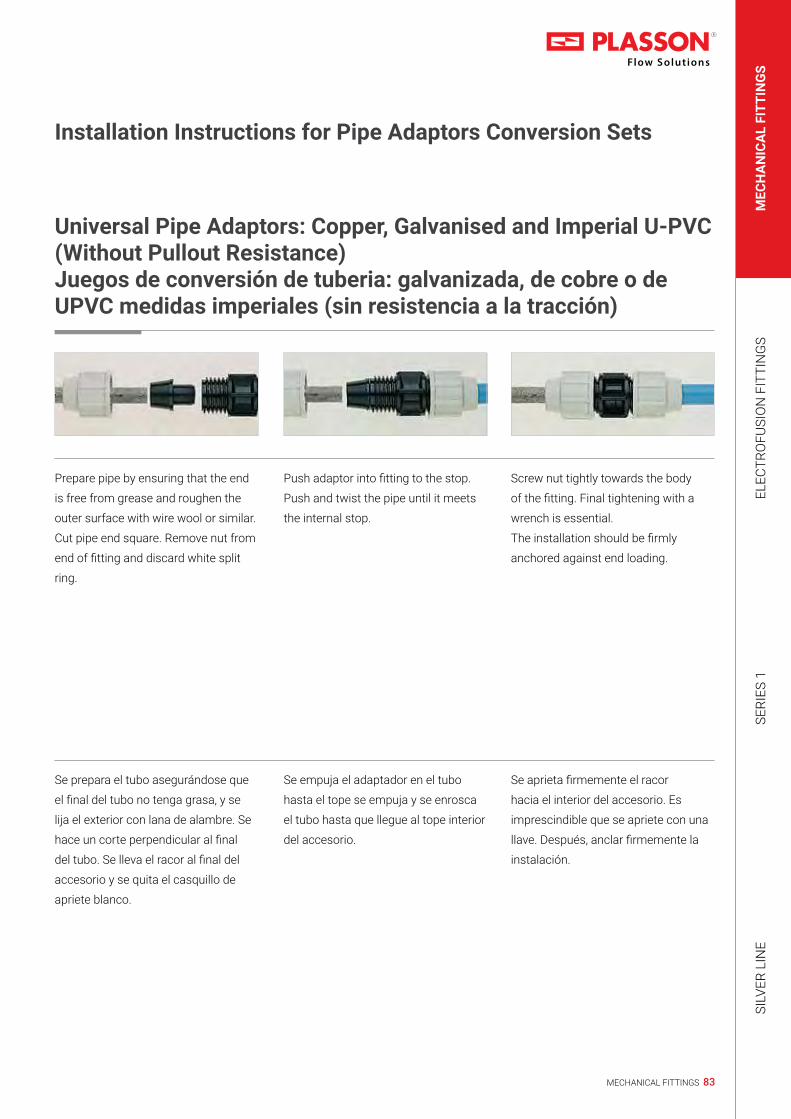
83MECHANICAL FITTINGS
MEC
HA
NIC
AL
FITT
ING
SEL
ECTR
OFU
SIO
N F
ITTI
NG
SSE
RIES
1SI
LVER
LIN
E
Installation Instructions for Pipe Adaptors Conversion Sets
Universal Pipe Adaptors: Copper, Galvanised and Imperial U-PVC (Without Pullout Resistance)Juegos de conversión de tuberia: galvanizada, de cobre o de UPVC medidas imperiales (sin resistencia a la tracción)
Prepare pipe by ensuring that the end
is free from grease and roughen the
outer surface with wire wool or similar.
Cut pipe end square. Remove nut from
end of fitting and discard white split
ring.
Push adaptor into fitting to the stop.
Push and twist the pipe until it meets
the internal stop.
Screw nut tightly towards the body
of the fitting. Final tightening with a
wrench is essential.
The installation should be firmly
anchored against end loading.
Se prepara el tubo asegurándose que
el final del tubo no tenga grasa, y se
lija el exterior con lana de alambre. Se
hace un corte perpendicular al final
del tubo. Se lleva el racor al final del
accesorio y se quita el casquillo de
apriete blanco.
Se empuja el adaptador en el tubo
hasta el tope se empuja y se enrosca
el tubo hasta que llegue al tope interior
del accesorio.
Se aprieta firmemente el racor
hacia el interior del accesorio. Es
imprescindible que se apriete con una
llave. Después, anclar firmemente la
instalación.

84 MECHANICAL FITTINGS
Technical catalogue 2019 | Installation Instructions
Installation Instructions for Pipe Adaptors Conversion Sets
Adaptor Set for Copper (With Pullout Resistance)Juego de adaptadores para cobre (con resistencia a traccion)
Cut pipe square. Remove burrs. Ensure
pipe is free of scratches, dents and
other imperfections. Remove nut
from fitting and discard white split
ring. Make a mark on the pipe to the
depth of the rubber insert. Assemble
nut, brown ring and stainless steel
ring onto pipe in that order. Ensure the
brown ring tapers towards the nut and
the stainless steel ring towards the
fitting body.
Push insert into fitting body fully up to
the flange.
Push pipe end into body of fitting.
Ensure to insert at least to the mark
you have made. Push both the rings
up to the insert flange and engage
nut. Use a Plasson wrench for final
tightening.
Corte el tubo a escuadra, limpie los
restos del corte. Asegure que el tubo
no este rayado, dentado, con virutas
o con otras imperfecciones. Se lleva
el racor hasta el final del accesorio y
se quita el casquillo de apriete blanco.
Se hace una marca en la superficie
del tubo que es la profundidad del
adaptador de goma. Se colocan el
racor, el anillo marrón y el anillo de
acero en el tubo, en este orden. Se
comprueba que el anillo marrón se
remata hacia la tuerca y el anillo de
acero hacia el interior del accesorio.
Introducir el adaptador en el interior
del accesorio hasta el final
Introducir el tubo en el interior
del accesorio. Comprobar que se
introduce por lo menos hasta la marca
hecha previamente. Se empujan
ambos anillos hasta el adaptador de
goma y se cierra firmemente el racor.
Para apretar firmemente se debe
utilizar la llave Plasson.

85MECHANICAL FITTINGS
MEC
HA
NIC
AL
FITT
ING
SEL
ECTR
OFU
SIO
N F
ITTI
NG
SSE
RIES
1SI
LVER
LIN
E
Installation Instructions for Pipe Adaptors Conversion Sets
Lead Pipe AdaptorAdaptadores para tuberias de plomo
Remove nut from fitting and discard
white split ring. Mount nut on pipe
followed by brown split ring and seal
ring.
Note for lead pipe adaptors: This product seals on the outside diameter of the pipe and it is therefore important that the lead
pipe is in good condition on the external part of the pipe where the seal is made. Variation in the lead piping sometimes results
in oversized pipes. In these circumstances it may be preferable to use the white split ring provided with the fitting.
Push both components onto the pipe
until the seal ring is 20mm from the
end of pipe and touching the split ring.
Enter pipe into fitting body and tighten
firmly with a wrench. (It is important
that the pipe is not pushed fully to the
stop in the fitting).
Nota: El sellado con este producto se realiza con el diámetro exterior del tubo, y por lo tanto es importante que el exterior de la
tubería de plomo esté en buen estado. Los variaciones en la tubería de plomo resultan a veces demasiado grandes. En estas
circunstancias es preferible usar el casquillo de apriete que está previsto con el accesorio.
Se empujan los dos componentes
hasta que el anillo de goma esté a
20mm del final del tubo, y tocando el
casquillo de apriete marrón.
Se lleva el racor al final del accesorio y
se quita el casquillo de apriete blanco.
Se monta el racor al tubo seguido por
el casquillo marrón y el anillo de goma.
Se introduce el tubo en el interior del
accesorio y se aprieta firmemente con
una llave (es importante que no se
empuje el racor completamente hasta
el final del accesorio).

86 MECHANICAL FITTINGS
Technical catalogue 2019 | Installation Instructions
Cut the pipe square and remove all burrs
and sharp edges.
Select correct fitting according to the
external diameter of the pipe.
Slide the PLASS4 fitting (universal side)
onto the pipe, until it reaches the internal
fins and a slight resistance is felt.
Do not force the pipe end past the fins.
Holding the PLASS4 body with a wrench,
tighten the PLASS4 universal nut firmly
with a wrench (size 35-50 tighten nut very
firmly to approx. 90 NM)
Assemble the metric PE joint as per the
standard fitting instructions.
Note: If reusing the fitting, ensure the metal
teeth are located in the grip ring and pipe
end does not pass the location fins in the
body.
Corte el tubo a escuadra y elimine todas
las virutas y cantos vivos.
Elija el accesorio apropiado de acuerdo con
el diámetro del tubo.
Introdusca el accesorio PLASS4 (del lado
Universal) en el tubo hasta que llegue al
tope s sienta una ligera resistencia.
No fuerce el tubo y no pase las aletas.
Agarrando el cuerpo del PLASS4 con una
llave apropiada, cierre firmamente el raccor
con una llave (en las medidas 35-50 su
raccor puede ser cerrado con un momento
de 90 Nm). Arme la union de PE como
en las instrucciones de los accesorios
normales.
IMPORTANTE: no fuerce el tubo y pase
el punto de resistencia. Puede danar el el
accesorio.
Comience apretar la tuerca al cuerpo. el
cierre final hagalo con una llave plasson
o similar. Ensamble la junta metrica
como las instrucciones de un accesorio
estandard.
Installation Instructions for Plass4 and Copper Pipe Adaptor (Universal Adaptor)
Installation Instructions for PLASS4 (Universal) FittingsInstrucciones para la instalacion de acsesorios plass4

87MECHANICAL FITTINGS
MEC
HA
NIC
AL
FITT
ING
SEL
ECTR
OFU
SIO
N F
ITTI
NG
SSE
RIES
1SI
LVER
LIN
E
Installation Instructions for Plass4 and Copper Pipe Adaptor (Universal Adaptor)
Cut the copper pipe square and remove all
burrs and sharp edges.
Twist the copper pipe into the fitting*
through the rubber o-ring to the pipe stop.
Tighten the nut firmly. Use a wrench for
final tightening. The nut should be closed
tightly, however there is no need for the nut
to actually meet the body shoulder.
Assemble the metric PE joint as per the
standard fitting instructions.
* Lubrication of the pipe end will ease the
insertion (use silicone lubricant).
Note: If reused, the metal grip ring must be
replaced with a new one.
Corte el tubo a escuadra y elimine todas
las virutas y cantos vivos.
Introduzca girando* el tubo de cobre junto
con el o-ring hasta el tope.
Apriete la tuerca firmemente. use una llave
para el apriete final. La tuerca debe estar
apretada hermeticamente. Sin embargo no
es necesario que llegue hasta el borde del
cuerpo.
Ensamble la junta metrica pe como un
accesorio estandard.
* Para facilitar la introduccion utilice un
lubricante a base de silicona.
NOTA: Si quiere reusar el accesorio debe
reemplazar el agarre de metal por uno
nuevo.
Installation Instructions for Copper Pipe AdaptorInstrucciones para la instalacion de adaptor tubo de cobre

88 MECHANICAL FITTINGS

89MECHANICAL FITTINGS
MEC
HA
NIC
AL
FITT
ING
SEL
ECTR
OFU
SIO
N F
ITTI
NG
SSE
RIES
1SI
LVER
LIN
E


92 ELECTROFUSION FITTINGS

93ELECTROFUSION FITTINGS
MEC
HAN
ICAL
FIT
TIN
GS
ELEC
TRO
FUSI
ON
FIT
TIN
GS
SERI
ES 1
SILV
ER L
INE
ElectroFusion System 94Table of Contents 96 - 101Fittings 102 - 144Wastewater Line 145 - 150Technical Specifications 151 - 153Controllers 154 - 157Installation Tools 168 - 176Minimum required Generator Output power 177Extension power cable size 178
PLASSON, a worldwide leader in fittings for polyethylene
pipes for over 40 years, now offers a complete line of
ElectroFusion products including: Plasson ElectroFusion
fittings, tools and control boxes.
Plasson ElectroFusion products combine to offer a reliable
smart-system solution featuring fully computerized control
and monitoring.
PLASSON’s customers benefit from the Company’s quality
products, expertise and worldwide first-rate service in
water, gas distribution, Waste-Water Systems, Geothermal
applications and industrial applications.
AustraliaPlasson Australia (PTY) Ltd.E-mail: [email protected]
BrasilPlasson Do BrasilE-mail: [email protected]
FrancePlasson France S.A.E-mail: [email protected]
GermanyPlasson GmbHE-mail: [email protected]
ItalyPlasson ItaliaE-mail: [email protected]
Sistema ElectroFusión 95Indice 96 - 101Accesorios 102 - 144Aguas residuales 145 - 150Especificaciones técnicas 151 - 153Soldadoras automáticas 158 - 167Herramientas de instalación 168 - 176Potencia mínima requerida de un generador de energía eléctrica, Potencia de salida
177
Cable alargador de alimentación 178
PLASSON, líder mundial en accesorios para tuberías de
polietileno desde hace más de 40 años, presenta ahora una
línea completa de productos de electrofusión, entre ellos:
conectores, herramientas y soldadoras automáticas de
ElectroFusión. La combinación de productos ElectroFusion
de Plasson ofrece una solución inteligente y confiable
que integra el control y la monitorización completamente
computarizados.
Los clientes de PLASSON se benefician de los productos
de calidad, la pericia y el excelente servicio mundial de la
compañía en instalaciones de distribución de agua y gas, y
aplicaciones industriales.
PolandPlasson Polska Sp.z o.o.E-mail: [email protected]
South AfricaPLASSON SA Pty Ltd, t/a PPAE-mail: [email protected]
SpainPlasson Spain S.L.E-mail: [email protected]
United KingdomPlasson UK Ltd.E-mail: [email protected]
USAPlasson USAE-mail: [email protected] www.plassonusa.com
IntroductionIntroducción
Subsidiary CompaniesSubsidiarias

94 ELECTROFUSION FITTINGS
Plasson ElectroFusion Fittings
Plasson fittings are specifically designed for reliable,
high performance pipe joining and long system life. This
automated system has been proven to be most economical
due to the low potential for operator error.
Tools and Control Box
Plasson offers quality tools and control boxes allowing
for easy installation. Plasson control boxes provide
computerized ElectroFusion with minimal potential for
operator error. The Plasson control boxes are the economical
solution for reliable ElectroFusion.
The Smart Fuse System - Plasson ElectroFusion
All Plasson products combine to form the latest state-of-
the-art high performance pipe joining solution. Plasson
ElectroFusion fittings are part of a complete ElectroFusion
Smart Fuse System. The entire ElectroFusion process is
executed and fully monitored by the computerized control
box. Everything is computer-controlled ensuring safe,
dependable connections.
Plasson ElectroFusion fittings can be used with Plasson’s
computerized Smart Fuse System control box or with
standard barcode systems. Each Plasson ElectroFusion
fitting comes complete with a barcode.
Advantages
Stronger pipe joining - Plasson ElectroFusion quality fittings
have long penetration depths and fusion zones which ensure
high quality joints.
Most Economical - Economic benefits are a result of
overall integrated system quality and innovation including
the computerized Smart Fuse System which reduces the
potential for operator error.
High Performance - Proven high performance in gas and
water distribution and industrial applications.
Superior Service - Plasson provides unmatched service
based on over 40 years in the field.
Plasson ElectroFusion Smart Fuse System Features
• Superior Fitting Design
increases joint integrity
• Automatic Controller
decreases potential operator error
• Computerized Data Retrieval
ensures quality control by Joint Data retrieval of
measurements and records
• Compatibility
between Plasson ElectroFusion and other ElectroFusion
systems through the computerized barcode system
• Easy Installation
using PLASSON’s simple, practical tools
• High Standards
are ensured by the latest product testing methods
Plasson ElectroFusion SystemThe Smart-System Solution You Can Depend On

95ELECTROFUSION FITTINGS
MEC
HAN
ICAL
FIT
TIN
GS
ELEC
TRO
FUSI
ON
FIT
TIN
GS
SERI
ES 1
SILV
ER L
INE
Accesorios ElectroFusion de Plasson
Los accesorios (“fittings”) de Plasson para tuberías han sido
especialmente diseñados para asegurar conexiones fiables, de
alto rendimiento y prolongada vida útil. Se ha comprobado que
este sistema automatizado es el más económico, gracias a la
escasa probabilidad de errores por parte del operador.
Herramientas y soldadora automática de ElectroFusión
Plasson ofrece herramientas de alta calidad y soldadoras
automáticas que se instalan fácilmente. Las soldadoras,
que proporcionan un proceso computarizado con mínima
probabilidad de error humano, son la solución más económica
para una electrofusión de máxima confianza.
ElectroFusion de Plasson - El sistema inteligente
Los productos de Plasson se combinan para ofrecer la solución
más avanzada y rendidora en la conexión de tuberías. Los
accesorios ElectroFusion de Plasson forman parte de un
sistema completo e inteligente. La soldadora automática de
ElectroFusión está a cargo de la ejecución y la monitorización
del proceso. El sistema controlado por computadora asegura
conexiones seguras y confiables.
Ventajas
Uniones más resistentes - Los accesorios de alta calidad
ElectroFusion de Plasson tienen grandes profundidades
de penetración y zonas de fusión que aseguran juntas muy
resistentes.
La solución más económica - El beneficio económico
es el resultado de la calidad y la innovación del sistema
computarizado totalmente integrado, que reduce la probabilidad
de error humano.
Alta performance - Elevado rendimiento comprobado en
instalaciones de distribución de gas y agua, y aplicaciones
industriales.
Excelente servicio - Plasson le brinda un servicio inigualado, con
su pericia y experiencia de más de 40 años en el terreno.
Características del sistema inteligente ElectroFusion de
Plasson
• Excelente diseño
asegura la integridad de la conexión
• Control automático
reduce la probabilidad de error humano
• Recuperación de datos
calidad asegurada mediante la recuperación de datos de
mediciones y registros
• Compatibilidad
con el sistema ElectroFusion de Plasson y otros sistemas de
códigos de barras
• Instalación sencilla
mediante las herramientas prácticas y simples de PLASSON
• Estándar elevado
asegurado por los métodos de prueba de productos de última
generación
Sistema ElectroFusion de PlassonLa solución inteligente de confianza

96 ELECTROFUSION FITTINGS
Technical catalogue 2019 | Content
490104/490103
Page 102 CouplerEnlace Recto
4901L4
Page 103 Long CouplerEnlace Largo
450104
Page 103 Coupler (PN 25)Enlace Recto (PN 25)
460104/460103
Page 104 LightFit Coupler (PN 10)Enlace LightFit (PN 10)
4601S3
Page 105 Super LightFit (PN 6.4)
491104
Page 105 Reducing CouplerEnlace Reductor
491107
Page 106 Spigot ReducerReductor Espiga
49009
Page 107 Flex Restraint
494204
Page 107 Monolithic End CapTapón Monolitico
491204
Page 108 End CapTapón
491207
Page 109 Spigot End PlugTapón Espiga
490404
Page 110 Tee 90°Enlace T 90°
492404
Page 110 Two Outlets Reducing TeeEnlace te Reductor con Salida Doble
491404
Page 111 Reducing TeeEnlace Reductor
499404
Page 112 Flanged TeeEnlace T Bridado
490504
Page 112 Elbow 90°Codo 90°
490604
Page 113 Elbow 45°Codo 45°
490804
Page 113 Elbow 22.5°Codo 22.5°
Fittings

97ELECTROFUSION FITTINGS
MEC
HAN
ICAL
FIT
TIN
GS
ELEC
TRO
FUSI
ON
FIT
TIN
GS
SERI
ES 1
SILV
ER L
INE
46060
Page 114 LightFit Elbow 45ºCodo LightFit 45°
46330
Page 114 LightFit Elbow 30ºCodo LightFit 30°
46370
Page 114 LightFit Elbow 15ºCodo LightFit 15°
490904
Page 115 Elbow 180°Codo 180°
491904
Page 115 Y ReducerY Reductor
491504
Page 116 Duckfoot Elbow 90°Codo 90° Empotrable
4915Q4
Page 116 Duckfoot Elbow 90° with OutletCodo 90° Empotrable con Toma de Servicio
4947C4
Page 117 Adjustable ElbowCodo Ajustable
4947D4
Page 117 Adjustable Elbow One SidedCodo Ajustable Enlace/Espiga
496804
Page 118 Balloon SaddleCollarín Globo
498304
Page 118 Monolithic Weld End Cap for Ballon SaddleTapón Monolítico Soldable para Collarín Globo
4958T
Page 119 Saddle BSPP Female OutletCollarín BSPP Rosca Hembra
495204
Page 119 Repair SaddleToma de Reparación
493804
Page 120 Transition SaddleCollarín de Transición
493803
Page 123 Sensor Adaptor with Brass Thread
495804
Page 124 Branch SaddleCollarín de Derivación
495804
Page 125 Branch SaddleCollarín de Derivación
495803
Page 126-127 XL&XXL Branch SaddleXL&XXL Collarín de Derivación

98 ELECTROFUSION FITTINGS
Technical catalogue 2019 | Content
4758W
Page 127 LightFit Branch SaddleCollarín de Derivación LightFit
495904
Page 128 Flange Branch SaddleCollarín bridado
495204
Page 129 Repair SaddleCollarín de reparación
496304
Page 129-130 Tapping SaddleToma de Servicio
4963P4
Page 131 Tapping Saddle Parallel OutletToma de Servicio Salida Parallel Outlet
498304
Page 132 Welding Cap for Tapping SaddleTapón Soldable para toma de Servicio
436207
Page 132 PE Ball ValveVálvula de Bola PE
495404/4954S4
Page 133-134 Tapping ValveToma de Servicio con Válvula
492104
Page 135 Male Transition CouplerEnlace de Transición Macho
493104
Page 135 Female Transition CouplerEnlace de Transición Hembra
492504
Page 136 Male Transition Elbow 90°Codo de Transición de 90° Macho
493504
Page 136 Female Transition Elbow 90°Codo de Transición de 90° Hembra
492604
Page 137 Male Transition Elbow 45°Codo de Transición de 45° Macho
493604
Page 137 Female Transition Elbow 45°Codo de Transición de 45° Hembra
494104
Page 138 Female Free Nut Transition CouplerEnlace de Transición Tuerca Libre Hembra
494504
Page 138 Female Transition Elbow 90°Codo de Transición de 90° Tuerca Libre, Hembra
494604
Page 139 Female Free Nut Transition Elbow 45°Codo de Transición de 45° Tuerca Libre Hembra
494404
Page 139 Female Union Free Nut Transition TeeEnlace T PE/Latón Tuerca Libre Hembra

99ELECTROFUSION FITTINGS
MEC
HAN
ICAL
FIT
TIN
GS
ELEC
TRO
FUSI
ON
FIT
TIN
GS
SERI
ES 1
SILV
ER L
INE
497104
Page 140 PE Male Transition CouplerEnlace de Transición PE Macho
497504
Page 140 PE Male Transition Elbow 90°Codo de Transición PE de 90° Macho
497604
Page 141 PE Male Transition Elbow 45°Codo de Transición PE de 45° Macho
497704
Page 141 PE Cast Iron Flange Transition CouplerEnlace de Transición Bridado - PE/Hierro Fundido
495704
Page 142 PE Cast Iron Spigot Transition CouplerEnlace de Transición Espiga - PE/Hierro Fundido
490209
Page 142 Full Face FlangeBrida de Cara Plana
490207
Page 143 Stub FlangeAdaptador de Brida
09903
Page 144 Flange Backing RingBrida Revestida
475804
Page 146 Wastewater Adjustable SaddleRamal para Aguas Residuales
4758A4
Page 146 Wastewater Saddle 45° Inlet 110Ramal 45° de Salida para Aguas Residuales
4758V4
Page 147 Wastewater Saddle PVC/PP Adaptor InletCollarin Lightfit de transicion para Aguas Residuales de PE A PP/PVC
4758S4
Page 147 Wastewater Saddle Spigot InletCollarín Lightfit para aguas residuales con salida espiga
4747D4
Page 148 Wastewater Adjustable Elbow One SidedCodo Ajustable para Aguas Residuales Enlace/Espiga
37020/477207
Page 148 Wastewater Manhole AdaptorAdaptador para Pozo de Aguas Residuales
4701V4
Page 149 Wastewater PE to PVC AdaptorAdaptador Para PE A PVC
4747V4
Page 149 Wastewater Adjustable Elbow PE to PVCCodo Ajustable de Transición de PE a PVC
470604
Page 150 Wastewater Elbow 45ºCodo 45º Para Aguas Residuales
Wastewater Line

100 ELECTROFUSION FITTINGS
Technical catalogue 2019 | Content
473304
Page 150 Wastewater Elbow 30ºCodo 30º Para Aguas Residuales
473704
Page 150 Wastewater Elbow 15ºCodo 15º Para Aguas Residuales
Controllers29143.0308S324
Page 155Page 159
PolyCode (USB + Bluetooth)PolyCode (USB)
29143.F0318V112
Page 155
Page 160-161
PolyControl Plus (USB + Bluetooth) V2.0PolyControl Plus (USB) V2.0
29143.0307.103
Page 156
Page 162-163
Polymatic Plus (USB + Bluetooth)Polymatic Plus (USB)
29143.0308T108
Page 156
Page 164-165
Tiny Data MF (USB + Bluetooth)Tiny Data MF (USB)
29143.0307.000
Page 157
Page 166-167
Monomatic Data (USB + Bluetooth)Monomatic Data (USB)
Page 168 Extension Key for Tapping ValveLlave de Extensión para Toma de Servicio Con Válvula
Page 168 Key for Tapping SaddleLlave para Toma de Servicio
Page 168 Hand ScrapersRaspatubos Manual
Page 168 Rotational Scraper ToolsRaspatubos Giratorios
Page 169 Plasson Scraper Tool for Pipe EndsRaspatubos Giratorio Plasson
Page 169 Pipe CutterCortadores de Tuberia
Page 169 Rotational Pipe Cutter (S-Type)Cortador de TuberÍa Giratorio (Tipo S)
Page 169 Rotational Pipe CuttersCortador de TuberÍa Giratorio
Page 170 Pipe Clamping ToolsHerramientas de Sujeción de Tubos
Installation Tools

101ELECTROFUSION FITTINGS
MEC
HAN
ICAL
FIT
TIN
GS
ELEC
TRO
FUSI
ON
FIT
TIN
GS
SERI
ES 1
SILV
ER L
INE
Page 170 Squeeze - Off ToolsPrensatubos
Page 171 Rounding RingsRedondeadores
Page 171 DetergentsDetergentes
Page 171 MarkersMarcadores
Page 172 Rounding ToolRedondeador hidráulico
Page 172 Tools for Wastewater SaddlesHerramientas para enlaces para aguas residuales
Page 173 Rotational Scraper ToolsRascador giratorio para tuberías de PEAD
Page 173 Electrical Saddle ScraperRascador eléctrico para tuberías de PEAD
Page 173 Core Drill Kit for Plasson-Saddle Outlet
Page 173 Drilling Machine
Page 173 Pressure Test Pump
Page 174 Hot Tapping Tool
Page 174 Saddle Pressing Tool
Page 174 Saddle Clamping Tool
Page 174 Saddle Clamping Tool
Page 175 Saddle Pressing and Clamping ToolsHerramientas necesarias para la instalación de Collarines de derivación y transición degran diámetro
Page 176 Core cutters- for each outlet sizeBrocas campana para cada diámetro
Page 176 Clamping Tool for Sensor Adaptor

102 ELECTROFUSION FITTINGS
Technical catalogue 2019 | Fittings
Coupler 490104
Enlace Recto
20mm up to 75mmL
L1
AdD
90mm up to 355mmL
L1
A
dD
Product Code Size d L L1 D A UC W
490104016 16 71 34 35 39 480 58490104020 20 76 37 31 34 440 50490104025 25 82 40 36 37 360 40490104032 32 88 42 44 42 256 64490104040 40 97 47 56 46 200 97490104050 50 101 49 67 51 132 147490104063 63 117 57 82 57 72 230490104075 75 126 61 98 64 60 340490104090 90 148 73 112 71 38 475490104110 110 163 80 135 81 23 718490104125 125 173 85 157 87 18 1075490104140 140 183 90 174 97 12 1295490104160N 160 195 93 194 105 6 1555490104180N 180 212 105 218 116 5 2112490104200N 200 223 109 242 126 4 2785490104225N 225 240 119 272 138 4 3900490104250 250 251 123 301 156 2 4461490104280 280 275 134 342 170 1 6440490104315 315 282 139 387 184 1 8845490104355 355 277 137 431 203 1 10200450103355 355 280 138 430 204 1 10438490103400 400 293 145 485 231 1 13800
490103
LL1
AdD
Product Code Size d L L1 D A UC* W
490103450 450 306 153 539 257 1 16000490103500 500 340 170 603 283 1 20200490103560 560 376 188 674 317 1 28000490103630 630 418 209 759 356 1 41100490103710 710 472 236 853 400 1 62000490103800 800 500 250 955 450 1 87000
* Due to product size, cannot be packed in standard carton | * Cantidad óptima para embalaje en dos pallets apilados

103ELECTROFUSION FITTINGS
MEC
HAN
ICAL
FIT
TIN
GS
ELEC
TRO
FUSI
ON
FIT
TIN
GS
SERI
ES 1
SILV
ER L
INE
Long Coupler 4901L4
Enlace Largo
L
L1
A
dD
Product Code Size d L L1 D A UC W
4901L4032 32 104 50 44 43 272 834901L4040 40 121 59 56 46 128 1354901L4050 50 139 68 68 51 96 2154901L4063 63 166 81 82 57 48 318
Coupler (PN 25) 450104
Enlace Recto (PN 25)
L
L1
AdD
LL1
A
dD
Product Code Size d L L1 D A UC W
450104050 50 100 49 68 52 132 147450104063 63 118 57 82 58 72 230450104075 75 126 62 97 65 60 339450104090 90 148 73 117 69 38 571450104110 110 163 80 140 79 23 835450104125 125 173 85 157 87 18 1075450104160 160 198 97 198 105 6 1780450104180 180 212 104 224 114 4 2449450104200 200 223 110 249 126 4 3295450104225 225 240 118 280 140 4 4366450104250 250 256 127 310 155 2 5507450104280 280 274 135 341 166 1 6369450104315 315 284 140 381 184 1 8884450103355 355 280 138 430 204 1 10438

104 ELECTROFUSION FITTINGS
Technical catalogue 2019 | Fittings
LightFit Coupler (PN10) 460104
Enlace LightFit (PN10)
LL1
A
dD
Product Code Size d L L1 D A UC W
460104040 40 90 43 56 47 200 96460104050 50 100 49 68 52 132 147460104063 63 118 57 77 57 112 158460104075 75 126 61 90 63 60 216460104090 90 148 72 108 69 44 360460104110 110 163 80 131 79 25 540460104125 125 173 85 149 87 20 740460104140 140 182 89 167 94 12 970460104160 160 198 97 193 104 6 1320460104180 180 212 104 215 114 5 1650460104200 200 232 114 235 127 4 2110460104225 225 240 118 264 141 4 2825460104250 250 256 126 293 155 2 3728460104280 280 275 135 332 166 1 4850460104315 315 284 140 374 184 1 6950460104355 355 280 138 421 204 1 7980460104400 400 296 146 474 227 1 12000
460103*
LL1
AdD
Product Code Size d L L1 D A UC* W
460103450 450** 310 155 518 255 1 11700460103450N 450 310 155 518 255 1 11700460103500 500** 340 170 576 283 1 16000460103560N 560 376 188 625 309 1 21510460103630N 630 400 200 706 347 1 27000460103710 710 472 236 817 400 1 43100460103800 800 500 250 913 450 1 57300460103900 900 500 250 1031 500 1 70000
* Due to product size, cannot be packed in standard carton | * Cantidad óptima para embalaje en dos pallets apilados** Without Straps | ** Sin correas

105ELECTROFUSION FITTINGS
MEC
HAN
ICAL
FIT
TIN
GS
ELEC
TRO
FUSI
ON
FIT
TIN
GS
SERI
ES 1
SILV
ER L
INE
Super LightFit (PN 6.4) 4601S3
Super LightFit (PN 6.4)
LL1
AdD
Product Code Size d L L1 D A UC W
4601S3500 500 300 150 550 272 1 118004601S3560 560 310 155 620 310 1 153004601S3630 630 320 160 693 346 1 182004601S3710 710 380 190 775 388 1 258004601S3800 800 400 200 876 438 1 347004601S31000 1000 440 220 1085 534 1 48000
Reducing Coupler 491104
Enlace Reductor
20x16mm up to 110x90mm
L
L2 L1
A1 A
dd1 DD1
125x90mm up to 180x125mm
L
L2 L1
AA1
dd1 DD1
Product Code Size dxd1 L A A1 L1 L2 D D1 UC W
491104020016 20 x 16 71 39 39 35 35 36 36 480 54491104025020 25 x 20 71 39 39 35 35 36 36 480 46491104032020 32 x 20 81 43 37 40 35 45 32 360 59491104032025 32 x 25 81 43 39 40 35 45 36 360 56491104040025 40 x 25 90 47 38 44 40 56 37 200 86491104040032 40 x 32 90 47 43 44 40 56 44 160 92491104050025 50 x 25 100 52 41 49 41 68 37 160 118491104050032 50 x 32 100 52 45 49 40 68 45 128 123491104050040 50 x 40 100 52 48 49 44 68 56 128 135491104063032 63 x 32 119 59 45 57 40 82 45 96 180491104063040 63 x 40 119 59 49 57 44 82 56 96 192491104063050 63 x 50 119 59 54 57 49 82 68 80 224491104075063 75 x 63 126 66 59 66 57 98 82 65 314491104090050 90 x 50 143 78 53 71 49 116 69 54 430491104090063 90 x 63 143 78 61 71 57 116 82 44 460491104090075 90 x 75 143 78 67 71 61 116 98 41 480491104110063 110 x 63 161 84 61 78 57 139 82 32 639491104110090 110 x 90 161 84 74 78 72 139 116 23 740491104125090 125 x 90 171 88 70 85 72 158 116 18 1019491104125110 125 x 110 171 88 80 85 78 158 141 18 1025491104160090 160 x 90 193 105 69 94 72 199 116 12 1440491104160110 160 x 110 193 105 80 94 81 199 141 12 1520491104160125 160 x 125 195 105 89 94 85 199 158 6 1570491104180125 180 x 125 212 116 87 103 85 222 158 6 2060

106 ELECTROFUSION FITTINGS
Technical catalogue 2019 | Fittings
Spigot Reducer 491107
Reductor Espiga
L
L2L1
dd1
Product Code Size dxd1 L L1 L2 UC W
491107032025 32 x 25 104 50 48 240 30491107040032 40 x 32 123 59 56 240 90491107050032 50 x 32 129 59 56 160 80491107050040 50 x 40 131 59 60 264 100491107063032 63 x 32 131 59 58 144 110491107063040 63 x 40 132 59 58 144 120491107063050 63 x 50 132 60 60 128 125491107075040 75 x 40 145 71 60 96 167491107075050 75 x 50 145 71 59 96 180491107075063 75 x 63 151 71 65 72 210491107090050 90 x 50 156 81 59 56 280491107090063 90 x 63 160 80 65 48 300491107090075 90 x 75 166 80 71 40 320491107110063 110 x 63 167 83 66 36 450491107110075 110 x 75 169 83 72 36 460491107110090 110 x 90 178 83 80 28 510491107125090 125 x 90 186 90 81 24 655491107125110 125 x 110 188 90 84 18 730491107140090 140 x 90 208 95 80 16 850491107140110 140 x 110 195 95 83 16 850491107140125 140 x 125 199 95 89 12 950491107160110 160 x 110 219 101 84 10 1150491107160125 160 x 125 206 101 88 16 1170491107160140 160 x 140 211 101 94 10 1270491107180125 180 x 125 221 107 89 10 1500491107180140 180 x 140 224 107 95 10 1600491107180160 180 x 160 225 107 100 8 1750491107200140 200 x 140 229 114 93 8 2200491107200160 200 x 160 233 115 100 6 2180491107200180 200 x 180 241 116 106 5 2350491107225160 225 x 160 295 132 123 — 3120491107225180 225 x 180 285 130 118 — 3320491107225200 225 x 200 272 126 120 — 3255491107250160 250 x 160 308 149 100 — 3705491107250180 250 x 180 316 151 105 — 4050491107250200 250 x 200 324 151 116 — 4380491107250225 250 x 225 330 155 122 — 4850491107280200 280 x 200 345 140 116 — 5850491107280225 280 x 225 335 142 122 — 6085491107280250 280 x 250 340 139 135 — 6540491107315225 315 x 225 365 150 125 — 7900491107315250 315 x 250 365 147 134 — 8100491107315280 315 x 280 365 150 145 — 8800491107355250 355 x 250 390 164 136 — 9100491107355280 355 x 280 390 164 139 — 9500491107355315 355 x 315 390 164 150 — 9890491107400280 400 x 280 415 179 139 — 10420491107400315 400 x 315 415 179 150 — 11130491107400355 400 x 355 420 179 164 — 11580
Maximum Pressure: PN 16 (cold water) | Presión Máxima: PN 16 (agua fria)Additional dimensions and pressure rated spigots are available upon requestLos tamaños y presiones no enunciados en la tabla están disponibles a pedido

107ELECTROFUSION FITTINGS
MEC
HAN
ICAL
FIT
TIN
GS
ELEC
TRO
FUSI
ON
FIT
TIN
GS
SERI
ES 1
SILV
ER L
INE
Flex Restraint 49009
Product Code Size L H B D1 D2 UC W
49009998 160-1600 237 60 65 13.5 11 — —
Flex Restraint 49009
Product Code Size L H B UC W
49009999 160-1600 202 40 65 60 300
Monolithic End Cap 494204
Tapón Monolítico
L
L1
A
d
D
Product Code Size d L L1 D A UC W
494204032 32 63 44 44 46 432 50494204040 40 70 48 55 51 256 75494204050 50 82 55 68 56 192 122494204063 63 95 62 81 62 96 182
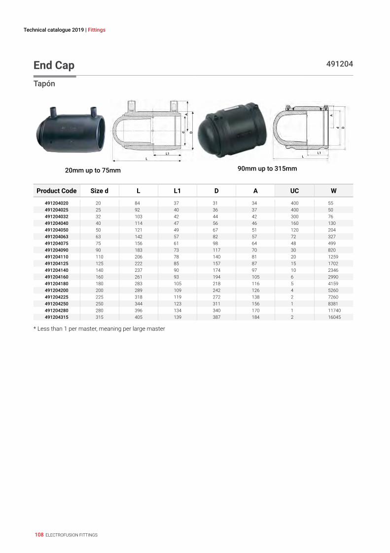
108 ELECTROFUSION FITTINGS
Technical catalogue 2019 | Fittings
End Cap 491204
Tapón
20mm up to 75mm
LL1
Ad D
90mm up to 315mm
LL1
A
d D
Product Code Size d L L1 D A UC W
491204020 20 84 37 31 34 400 55491204025 25 92 40 36 37 400 50491204032 32 103 42 44 42 300 76491204040 40 114 47 56 46 160 130491204050 50 121 49 67 51 120 204491204063 63 142 57 82 57 72 327491204075 75 156 61 98 64 48 499491204090 90 183 73 117 70 30 820491204110 110 206 78 140 81 20 1259491204125 125 222 85 157 87 15 1702491204140 140 237 90 174 97 10 2346491204160 160 261 93 194 105 6 2990491204180 180 283 105 218 116 5 4159491204200 200 289 109 242 126 4 5260491204225 225 318 119 272 138 2 7260491204250 250 344 123 311 156 1 8381491204280 280 396 134 340 170 1 11740491204315 315 405 139 387 184 2 16045
* Less than 1 per master, meaning per large master
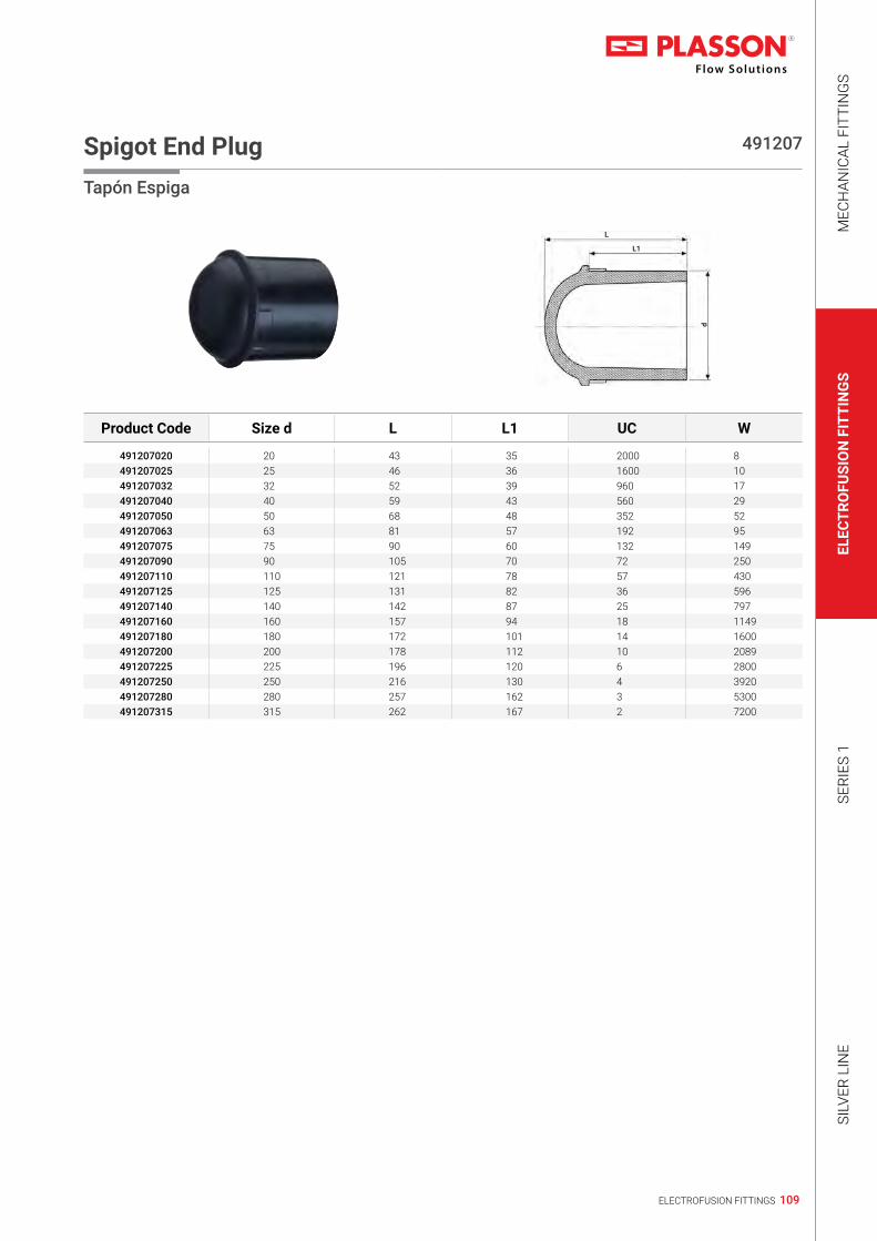
109ELECTROFUSION FITTINGS
MEC
HAN
ICAL
FIT
TIN
GS
ELEC
TRO
FUSI
ON
FIT
TIN
GS
SERI
ES 1
SILV
ER L
INE
Spigot End Plug 491207
Tapón Espiga
L
L1
d
Product Code Size d L L1 UC W
491207020 20 43 35 2000 8491207025 25 46 36 1600 10491207032 32 52 39 960 17491207040 40 59 43 560 29491207050 50 68 48 352 52491207063 63 81 57 192 95491207075 75 90 60 132 149491207090 90 105 70 72 250491207110 110 121 78 57 430491207125 125 131 82 36 596491207140 140 142 87 25 797491207160 160 157 94 18 1149491207180 180 172 101 14 1600491207200 200 178 112 10 2089491207225 225 196 120 6 2800491207250 250 216 130 4 3920491207280 280 257 162 3 5300491207315 315 262 167 2 7200

110 ELECTROFUSION FITTINGS
Technical catalogue 2019 | Fittings
Tee 90º 490404
Enlace T 90°
20mm up to 75mm
LL1
d1
H
d D
90mm up to 250mm
LL1
d1
H
d D
Product Code Size dxd1xd L L1 D H A UC W
490404020 20 x 20 x 20 96 37 33 60 39 260 61490404025 25 x 25 x 25 103 39 44 66 43 168 110490404032 32 x 32 x 32 104 39 44 74 43 144 97490404040 40 x 40 x 40 120 43 56 90 47 96 165490404050 50 x 50 x 50 139 48 68 102 52 56 257490404063 63 x 63 x 63 167 58 82 119 58 32 417490404075 75 x 75 x 75 196 63 96 129 62 26 639490404090 90 x 90 x 90 294 71 113 137 71 15 1090490404110 110 x 110 x 110 326 71 143 160 81 8 1955490404125 125 x 125 x 125 382 86 165 177 88 4 2950490404160 160 x 160 x 160 396 97 209 222 105 3 4758490404180 180 x 180 x 180 422 106 245 250 116 1 7200490404200 200 x 200 x 200 451 114 261 265 125 1 8650490404225 225 x 225 x 225 494 122 293 290 140 1 11860490404250 250 x 250 x 250 538 129 326 315 152 1 16250
Two Outlets Reducing Tee 492404
Enlace te Reductor con Salida Doble
L
L1
L2
d1
H
d D
Product Code Size dxd1 - d1xd L L1 L2 D H A UC W
492404040025 40 x 25 - 25 x 40 176 46 57 56 72 46 96 229492404040032 40 x 32 - 32 x 40 176 46 57 56 76 46 75 233492404050025 50 x 25 - 25 x 50 195 49 65 68 79 51 56 342492404050032 50 x 32 - 32 x 50 195 49 65 68 83 51 58 336492404050040 50 x 40 - 40 x 50 195 49 65 68 89 51 52 352492404063025 63 x 25 - 25 x 63 213 58 65 82 86 57 42 457492404063032 63 x 32 - 32 x 63 213 58 65 82 90 57 40 464492404063040 63 x 40 - 40 x 63 213 58 65 82 96 57 36 480

111ELECTROFUSION FITTINGS
MEC
HAN
ICAL
FIT
TIN
GS
ELEC
TRO
FUSI
ON
FIT
TIN
GS
SERI
ES 1
SILV
ER L
INE
Reducing Tee 491404
Enlace T Reductor
LL1
d1
H
d D
20mm up to 75mm 90mm up to 250mm
LL1
d1
H
d D
Product Code Size dxd1xd L L1 D H A UC W
491404025020 25 x 20 x 25 104 39 44 66 43 168 108491404025032 25 x 32 x 25* 104 39 44 74 43 168 116491404032020 32 x 20 x 32 104 39 44 66 43 144 89491404032025 32 x 25 x 32 104 39 44 66 43 144 91491404040020 40 x 20 x 40 120 43 56 72 47 96 151491404040025 40 x 25 x 40 120 43 56 72 47 96 150491404040032 40 x 32 x 40 120 43 56 75 47 96 152491404050020 50 x 20 x 50 139 48 68 78 52 64 224491404050025 50 x 25 x 50 139 48 68 78 52 64 225491404050032 50 x 32 x 50 139 48 68 86 52 64 228491404050040 50 x 40 x 50 139 48 68 90 52 64 237491404063020 63 x 20 x 63 167 49 82 85 58 40 348491404063032 63 x 32 x 63 167 58 82 93 58 32 353491404063040 63 x 40 x 63 167 58 82 104 58 32 365491404063050 63 x 50 x 63 167 58 82 109 58 32 381491404075063 75 x 63 x 75 196 63 96 122 62 26 607491404090063 90 x 63 x 90 294 68 113 124 71 15 1050491404110063 110 x 63 x 110 326 71 143 134 81 9 1715491404110090 110 x 90 x 110 326 71 143 147 81 8 1815491404125090 125 x 90 x 125 382 86 165 161 88 5 2805491404125110 125 x 110 x 125 382 86 165 173 88 5 2859491404160090 160 x 90 x 160 396 97 209 192 105 3 4185491404160110 160 x 110 x 160 440 86 208 193 106 3 4470491404160125 160 x 125 x 160 440 86 208 198 106 3 4470491404180090 180 x 90 x 180 422 106 245 200 116 2 6090491404180110 180 x 110 x 180 422 106 245 219 116 2 6270491404180125 180 x 125 x 180 422 106 245 225 116 2 6410491404180140 180 x 140 x 180 422 106 245 237 116 1 6610491404180160 180 x 160 x 180 422 106 245 250 116 1 6950491404200090 200 x 90 x 200 451 114 261 205 125 2 7140491404200110 200 x 110 x 200 451 114 261 210 125 2 7235491404225090 225 x 90 x 225 494 122 293 220 140 1 9900491404225110 225 x 110 x 225 494 122 293 225 140 1 10000491404250090 250 x 90 x 250 538 129 326 235 152 1 13350491404250110 250 x 110 x 250 538 129 326 240 152 1 13400
* This size enlarges | * Esta media agranda

112 ELECTROFUSION FITTINGS
Technical catalogue 2019 | Fittings
Flanged Tee 499404
Enlace T Bridado
L
DN
S
DP
L1
d1
D1
H
t
d D
Product Code Size d x DN x d L L1 D H A D1 t s d1 DP UC W
499404090080 90 x 80 x 90 294 71 113 165 71 200 20 8 x 18 138 160 8 2835499404110080 110 x 80 x 110 326 71 143 181 81 200 20 8 x 18 138 160 6 3560499404110100 110 x 100 x 110 326 71 143 181 81 220 22 8 x 18 158 180 6 4240499404125080 125 x 80 x 125 382 86 165 190 88 200 20 8 x 18 138 160 4 4550499404125100 125 x 100 x 125 382 86 165 190 88 220 22 8 x 18 158 180 3 5180499404160080 160 x 80 x 160 440 86 208 210 106 200 20 8 x 18 138 160 3 6245499404160100 160 x 100 x 160 440 86 208 210 106 220 22 8 x 18 158 180 3 6785499404180080 180 x 80 x 180 422 106 245 225 116 200 20 8 x 18 138 160 2 7745499404180100 180 x 100 x 180 422 106 245 225 116 220 22 8 x 18 158 180 1 8550499404200080 200 x 80 x 200 451 114 261 240 125 200 20 8 x 18 138 160 1 8530499404200100 200 x 100 x 200 451 114 261 245 125 220 22 8 x 18 158 180 1 9230499404225080 225 x 80 x 225 494 122 293 255 140 200 20 8 x 18 138 160 1 11240499404225100 225 x 100 x 225 494 122 293 260 140 220 22 8 x 18 158 180 1 11900499404250080 250 x 80 x 250 538 129 326 270 152 200 20 8 x 18 138 160 1 14750499404250100 250 x 100 x 250 538 129 326 275 152 220 22 8 x 18 158 180 1 15400
Elbow 90º 490504
Codo 90°
D
d
L1L
20mm up to 75mm D
d
L1
L
90mm up to 250mm
Product Code Size d L L1 D A UC W
490504020 20 66 35 36 38 320 65490504025 25 66 37 36 38 320 52490504032 32 83 40 44 43 192 85490504040 40 92 44 55 47 120 138490504050 50 108 48 68 52 72 211490504063 63 131 57 81 59 40 320490504075 75 158 69 97 62 33 527490504090 90 213 78 113 69 19 875490504110 110 243 79 143 79 9 1519490504125 125 271 100 165 89 7 2424490504140 140 309 93 183 94 4 3024490504160 160 323 87 209 106 3 3990490504180 180 412 105 244 115 2 7590490504200 200 449 112 262 124 1 8670490504225 225 498 121 295 140 1 12200490504250 250 550 130 327 152 1 13500

113ELECTROFUSION FITTINGS
MEC
HAN
ICAL
FIT
TIN
GS
ELEC
TRO
FUSI
ON
FIT
TIN
GS
SERI
ES 1
SILV
ER L
INE
Elbow 45º 490604
Codo 45°
D
dL1
L32mm up to 75mm 90mm up to 250mm
D
d
L1L
Product Code Size d L L1 D A UC W
490604032 32 95 39 45 43 240 75490604040 40 108 42 55 46 160 117490604050 50 125 49 68 51 96 181490604063 63 148 57 81 59 60 264490604075 75 180 71 96 62 40 426490604090 90 243 75 112 69 22 759490604110 110 271 81 143 78 12 1269490604125 125 304 86 165 88 8 2030490604140 140 342 92 182 95 5 2471490604160 160 350 95 209 105 4 3990490604180 180 434 105 244 114 2 6150490604200 200 472 112 261 125 1 7050490604225 225 520 120 294 140 1 9800490604250 250 571 129 326 151 1 13400
Elbow 22.5º 490804
Codo 22.5°
Dd
L1
L
Product Code Size d L L1 D A UC W
490804090 90 214 72 113 71 26 665490804110 110 232 71 143 81 14 1087490804125 125 274 86 165 88 8 1850490804160 160 302 86 209 106 5 2930490804180 180 391 105 244 115 2 5360

114 ELECTROFUSION FITTINGS
Technical catalogue 2019 | Fittings
LightFit Elbow 45º 46060
Codo LightFit 45°
D d
L1L
Product Code Size d L L1 D A UC W
460604160 160 323 98 193 106 4 1976
LightFit Elbow 30º 46330
Codo LightFit 30°D d
L1L
Product Code Size d L L1 D A UC W
463304160 160 300 98 193 106 4 1798
LightFit Elbow 15º 46370
Codo LightFit 15°
D d
L1L
Product Code Size d L L1 D A UC W
463704160 160 265 98 193 106 6 1728

115ELECTROFUSION FITTINGS
MEC
HAN
ICAL
FIT
TIN
GS
ELEC
TRO
FUSI
ON
FIT
TIN
GS
SERI
ES 1
SILV
ER L
INE
Elbow 180º 490904
Codo 180°
d
L1
H
LB
Product Code Size d L L1 H B UC W
490904025 25 38 38 99 72 216 169490904032 32 44 41 108 88 144 216490904040 40 53 48 123 106 80 323
Y Reducer 491904
Y ReductorL
AB
d1
d
L1
H
Product Code Size d x d1 x d1 L L1 B A H UC W
491904032025 32 x 25 x 25 36 40 70 38 119 200 97491904040032 40 x 32 x 32 45 43 87 42 133 120 151491904050040 50 x 40 x 40 56 46 108 46 151 72 242

116 ELECTROFUSION FITTINGS
Technical catalogue 2019 | Fittings
Duckfoot Elbow 90º 491504
Codo 90° Empotrable
L
A1
D d
L1
H
Product Code Size d L L1 D A A1 H UC W
491504090 90 261 69 112 71 115 146 5 2260
Duckfoot Elbow 90º With Outlet 4915Q4
Codo 90° Emportable con toma de servicio
L
A1
D d
L1
d1
H
Product Code Size d x d1 L L1 D A A1 H UC W
4915Q4090032 90 x 32 261 69 112 71 115 146 5 2265

117ELECTROFUSION FITTINGS
MEC
HAN
ICAL
FIT
TIN
GS
ELEC
TRO
FUSI
ON
FIT
TIN
GS
SERI
ES 1
SILV
ER L
INE
Adjustable Elbow 4947C4
Codo Ajustable
L (max, when straight)
A
L1
24ºM
AX.
Dd
Product Code Size d L L1 D A UC W
4947C4090 90 341 72 116 77 12 14504947C4110 110 362 80 140 83 8 20304947C4125 125 382 85 157 95 8 26304947C4160 160 453 97 215 106 3 45104947C4180 180 511 104 224 128 2 74904947C4200 200 512 104 250 125 2 97334947C4225 225 600 105 282 141 1 132304947C4250 250 644 123 312 156 1 16775
Adjustable Elbow One Sided 4947D4
Codo Ajustable Enlace/Espiga
L (max, when straight)
A
L1L2
D1
12ºMAX.
Dd
Product Code Size d x D1 L L1 L2 D A UC W
4947D4090 90 x 90 258 72 82 116 77 20 9404947D4110 110 x 110 276 85 85 140 83 12 12904947D4125 125 x 125 292 90 90 157 95 12 17404947D4160 160 x 160 341 97 100 215 106 4 31504947D4180 180 x 180 365 138 138 223 128 3 42104947D4200 200 x 200 370 104 116 250 125 2 61724947D4225 225 x 225 426 105 124 282 141 2 83404947D4250 250 x 250 455 123 134 312 156 1 10800

118 ELECTROFUSION FITTINGS
Technical catalogue 2019 | Fittings
Balloon Saddle 496804
Collarín Globo
L
D
G
ød
B
H1
H
Product Code Size d x G B H H1 D L UC W
496804090025 90 x 2.1/2" 142 105 70 90 176 10 1961496804110025 110 x 2.1/2" 160 105 70 90 176 10 1973496804125025 125 x 2.1/2" 169 105 70 90 176 10 1981496804140025 140 x 2.1/2" 174 105 70 90 176 10 2000496804160025 160 x 2.1/2" 176 105 70 90 176 10 1984496804180025 180 x 2.1/2" 182 105 70 90 176 10 1997496804200025 200 x 2.1/2" 202 105 70 90 176 10 1991496804225025 225 x 2.1/2" 227 105 70 90 176 10 2003496804250025 250 x 2.1/2" 252 105 70 90 176 10 2010
Monolithic Weld End Cap for Balloon Saddle 498304
Tapón Monolítico Soldable para collarín globo
LL1
d
A
D
Product Code Size d L L1 D A UC W
498304090 90 123 77 117 77 55 479
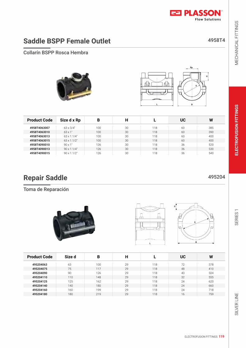
119ELECTROFUSION FITTINGS
MEC
HAN
ICAL
FIT
TIN
GS
ELEC
TRO
FUSI
ON
FIT
TIN
GS
SERI
ES 1
SILV
ER L
INE
Saddle BSPP Female Outlet 4958T4
Collarín BSPP Rosca Hembra
L B
Rp
d
H
Product Code Size d x Rp B H L UC W
4958T4063007 63 x 3/4" 100 30 118 60 3854958T4063010 63 x 1" 100 30 118 60 3904958T4063013 63 x 1.1/4" 100 30 118 60 4004958T4063015 63 x 1.1/2" 100 30 118 60 4004958T4090010 90 x 1" 126 30 118 36 5204958T4090013 90 x 1.1/4" 126 30 118 36 5304958T4090015 90 x 1.1/2" 126 30 118 36 540
Repair Saddle 495204
Toma de Reparación
L B
d
H
Product Code Size d B H L UC W
495204063 63 100 29 118 72 378495204075 75 117 29 118 48 410495204090 90 126 29 118 40 504495204110 110 148 29 118 32 555495204125 125 162 29 118 24 620495204140 140 180 29 118 24 660495204160 160 199 29 118 24 718495204180 180 219 29 118 16 759
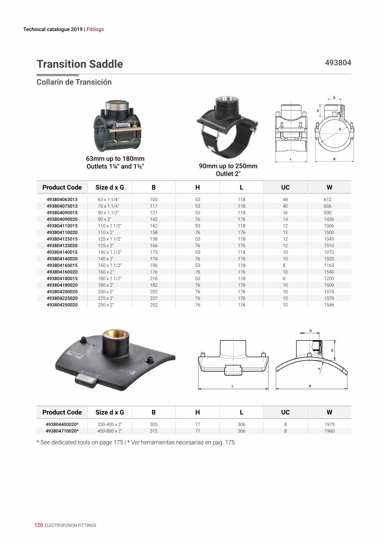
120 ELECTROFUSION FITTINGS
Technical catalogue 2019 | Fittings
Transition Saddle 493804
Collarín de Transición
63mm up to 180mmOutlets 1¼" and 1½" 90mm up to 250mm
Outlet 2"
L B
G
d
H
Product Code Size d x G B H L UC W
493804063013 63 x 1.1/4" 100 53 118 48 612493804075013 75 x 1.1/4" 117 53 118 40 656493804090015 90 x 1.1/2" 121 53 118 16 930493804090020 90 x 2" 142 76 176 14 1436493804110015 110 x 1.1/2" 142 53 118 12 1006493804110020 110 x 2" 158 76 176 12 1500493804125015 125 x 1.1/2" 158 53 118 12 1049493804125020 125 x 2" 166 76 176 12 1510493804140015 140 x 1.1/2" 175 53 118 10 1072493804140020 140 x 2" 174 76 176 10 1520493804160015 160 x 1.1/2" 196 53 118 8 1163493804160020 160 x 2" 176 76 176 10 1540493804180015 180 x 1.1/2" 216 53 118 6 1200493804180020 180 x 2" 182 76 176 10 1500493804200020 200 x 2" 202 76 176 10 1575493804225020 225 x 2" 227 76 176 10 1570493804250020 250 x 2" 252 76 176 10 1546
L B
G
d
H
Product Code Size d x G B H L UC W
493804400020* 250-400 x 2" 305 77 306 8 1975493804710020* 450-800 x 2" 315 77 306 8 1960
* See dedicated tools on page 175 | * Ver herramientas necesarias en pag. 175

PLASSON ALTERNATIVE
PLASSON ElectroFusion SaddlesFor Large Diameter PE Pipes
495804 | 5958B
4758W
495904
495803
495204
493804
NEW!
NEW!

PE has become well established in pipeline applications since its introduction in the 1950s.The numerous benefits of PE material include its flexibility, corrosion resistance and the option of fully welded systems, all leading to PE systems being used in a wide field of applications and increasingly larger diameters.Plasson, in keeping with latest market trends, continues to develop innovative fittings and installation tools, providing the end users all that is required in order to perform their task in the most convenient and professional way.Plasson Electrofusion fittings are designed for optimal performance using FEA (Final Element Analysis) software. The combination of engineering experience gained over 25 years, and use of leading PE 100 materials in the market provide for an estimated service life of over 100 years.
PLASSON Sensor AdaptorPlasson Sensor Adaptor provides a dedicated solution for connecting the sensor to the piping system, eliminating the need to apply leak-prone improvised connections. Plasson's Sensor adaptors enable quick and easy integration of various sensors onto a wide range of PE pipe diameters. Pressure rated Water PN16, Gas PE100 SDR11. Threaded brass/Stainless Steel Outlets according to ISO 7-1 (Female Rp thread), available in dimensions 1/2", 3/4" and 1".
Universal• Two Saddles cover extensive range of pipe diameters:• 110 (4" IPS ) – 400mm (16" IPS)• 450 (18" IPS ) – 1200mm (48" IPS)
Fast and simple installationThe Sensor Adaptor is designed to deal with the challenges of connecting to large PE pipes, such as ovality and deformation resulting from aging, handling and storage by obtaining full contact along the welding zone.Using one of the two unique yet simple clamping devise options (Strap or Bolt) ensures the correct welding of the Sensor Adaptor.• Correct tightening force indicator on strap mechanism
Specifications The fittings are tested and approved to meet the following standard requirements:ISO 4427, Part 3 (Water), ISO 4437, Part 3 (Gas)EN 12201, Part 3 (Water), EN 1555, Part 3 (Gas)AS/NZS 4129: 2008DVGW GW 335-B2
www.plasson.com
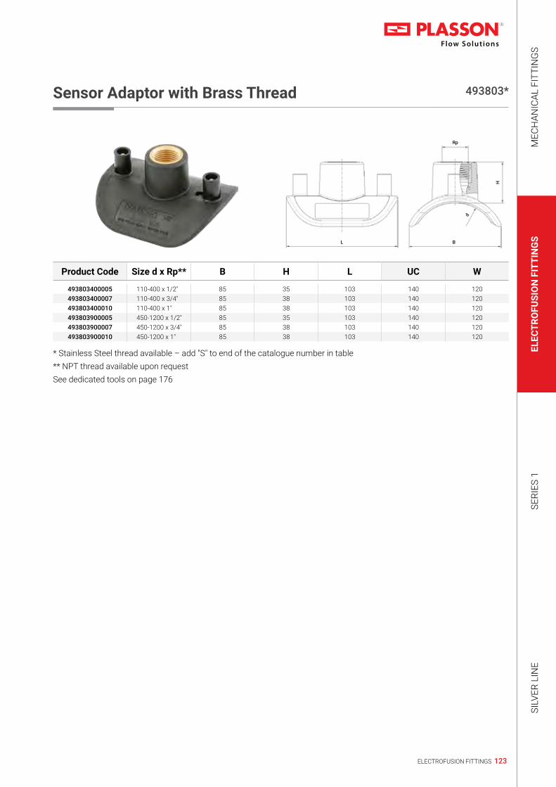
123ELECTROFUSION FITTINGS
MEC
HAN
ICAL
FIT
TIN
GS
ELEC
TRO
FUSI
ON
FIT
TIN
GS
SERI
ES 1
SILV
ER L
INE
Sensor Adaptor with Brass Thread 493803*
L B
Rp
d
H
Product Code Size d x Rp** B H L UC W
493803400005 110-400 x 1/2" 85 35 103 140 120493803400007 110-400 x 3/4" 85 38 103 140 120493803400010 110-400 x 1" 85 38 103 140 120493803900005 450-1200 x 1/2" 85 35 103 140 120493803900007 450-1200 x 3/4" 85 38 103 140 120493803900010 450-1200 x 1" 85 38 103 140 120
* Stainless Steel thread available – add "S" to end of the catalogue number in table** NPT thread available upon requestSee dedicated tools on page 176

124 ELECTROFUSION FITTINGS
Technical catalogue 2019 | Fittings
Branch Saddle 495804
Collarín de Derivación
200mm up to 315mmand all sizes with Outlet 90mm
63mm up to 180mmOutlets 32mm to 63mm
L B
d1
d
H1H
Product Code Size d x d1 B H H1 L Max Cutting Dia UC W
495804063032 63 x 32 100 59 49 118 23 56 394495804063040 63 x 40 100 78 66 118 29.5 40 400495804063050 63 x 50 100 93 82 118 37.5 40 430495804063063 63 x 63 100 94 85 118 45 40 462495804075032 75 x 32 117 59 49 118 23 48 431495804075040 75 x 40 117 78 66 118 29.5 36 451495804075050 75 x 50 117 93 82 118 37.5 32 465495804075063 75 x 63 117 94 85 118 45 32 522495804090032 90 x 32 126 59 49 118 23 32 519495804090040 90 x 40 126 78 68 118 29.5 32 529495804090050 90 x 50 126 93 82 118 37.5 32 550495804090063 90 x 63 126 94 85 118 45 24 608495804090090 90 x 90 139 105 90 176 66 15 934495804110032 110 x 32 148 59 49 118 23 24 585495804110040 110 x 40 148 78 68 118 29.5 24 598495804110050 110 x 50 148 93 82 118 37.5 20 629495804110063 110 x 63 148 94 85 118 45 20 658495804110090 110 x 90 162 105 90 176 68 18 949495804125032 125 x 32 162 59 49 118 23 24 634495804125040 125 x 40 162 78 68 118 29.5 20 644495804125050 125 x 50 162 93 82 118 37.5 20 670495804125063 125 x 63 162 94 85 118 45 16 703495804125090 125 x 90 169 105 90 176 68 18 953495804140032 140 x 32 180 59 49 118 23 24 661495804140040 140 x 40 180 78 68 118 29.5 16 677495804140050 140 x 50 180 93 82 118 37.5 16 705495804140063 140 x 63 180 94 85 118 45 16 740495804140090 140 x 90 174 105 90 176 68 16 965495804160032 160 x 32 200 59 49 118 23 16 744495804160040 160 x 40 200 78 68 118 29.5 16 757495804160050 160 x 50 200 93 82 118 37.5 16 778495804160063 160 x 63 200 94 85 118 45 16 804495804160090 160 x 90 176 105 90 176 68 16 961495804180032 180 x 32 219 59 49 118 23 16 800495804180040 180 x 40 219 78 68 118 29.5 12 800495804180050 180 x 50 219 93 82 118 37.5 12 828495804180063 180 x 63 219 94 85 118 45 12 886495804180090 180 x 90 182 105 90 176 68 15 962495804200063 200 x 63 202 102 85 176 47 15 862495804200090 200 x 90 202 105 90 176 68 15 900495804225063 225 x 63 227 102 85 176 47 15 882495804225090 225 x 90 227 105 90 176 68 15 983495804250063 250 x 63 252 102 85 176 47 15 970495804250090 250 x 90 252 105 90 176 68 15 1070495804280090 280 x 90 282 105 90 176 68 10 990495804315090 315 x 90 317 105 90 176 68 15 1005

125ELECTROFUSION FITTINGS
MEC
HAN
ICAL
FIT
TIN
GS
ELEC
TRO
FUSI
ON
FIT
TIN
GS
SERI
ES 1
SILV
ER L
INE
Branch Saddle* 495804
Collarín de Derivación*
L B
d1
D
d
H1H
Product Code Size d x d1 B H H1 L UC W
495804400090T 250 - 400 x 90 305 102 115 300 7 1510495804400110T 250 - 400 x 110 305 104 117 300 7 1650495804400125T 250 - 400 x 125 305 119 110 300 6 1760495804400160T 280 - 400 x 160 305 119 132 300 6 2167495804710090T 450 - 800 x 90 315 105 117 300 7 1598495804710110T 450 - 800 x 110 315 105 117 300 7 1601495804710125T 450 - 800 x 125 315 109 117 300 7 1739495804710160T 450 - 800 x 160 315 115 130 300 6 2017
** See dedicated tools on page 175 | ** Ver herramientas necesarias en pag. 175

126 ELECTROFUSION FITTINGS
Technical catalogue 2019 | Fittings
XL&XXL Branch Saddle** NEW! 495803
XL&XXL Collarín de Derivación**
Product Code d x d1 B L H H1 D UC W
495803355250T 315-355 x 250 390 420 140 200 16 1 7400495803400180T 400 x 180 386 470 135 169 16 1 —495803400200T 400 x 200 386 470 142 180 16 1 5700495803400225T 400 x 225 386 470 150 189 16 1 6000495803400250T 400 x 250 386 470 160 215 16 1 7900495803450180T 450 x 180 400 470 135 169 16 1 5000495803450200T 450 x 200 400 470 142 180 16 1 —495803450250T 450 x 250 400 470 160 195 16 1 7600495803450280T 450 x 280 450 530 169 225 16 1 —495803450315T 450 x 315 450 530 180 220 16 1 13000495803500180T 500 x 180 413 470 135 169 16 1 —495803500200T 500 x 200 413 470 142 180 16 1 5200495803500225T 500 x 225 413 470 150 189 16 1 6200495803500280T 500 x 280 465 530 169 225 16 1 —495803500315T 500 x 315 480 540 180 227 16 1 13500495803500355T 500 x 355 500 610 194 252 16 1 —495803630250T 500 - 630 x 250 400 420 203 225 16 1 6670495803560180T 560 x 180 421 470 135 169 16 1 —495803560200T 560 x 200 421 470 142 180 16 1 —495803560225T 560 x 225 421 470 150 189 16 1 6500495803560280T 560 x 280 477 530 169 225 16 1 —495803560315T 560 x 315 472 540 180 227 16 1 12800495803560355T 560 x 355 512 610 194 252 16 1 —495803560400T 560 x 400 505 620 209 258 16 1 20100495803630180T 630 x 180 425 470 135 169 16 1 —495803630200T 630 x 200 425 470 142 180 16 1 5900495803630225T 630 x 225 425 470 150 189 16 1 6200495803630280T 630 x 280 489 530 169 225 16 1 —495803630315T 630 x 315 481 540 180 227 16 1 12700495803630355T 630 x 355 522 610 194 252 16 1 —495803630400T 630 x 400 520 620 209 258 16 1 20400495803710180T 710 x 180 434 470 135 169 16 1 —495803710200T 710 x 200 434 470 142 180 16 1 5400495803710225T 710 x 225 434 470 150 187 16 1 6400495803710250T 710 x 250 434 470 160 195 16 1 7500495803710280T 710 x 280 498 530 169 225 16 1 —495803710315T 710 x 315 500 530 180 220 16 1 12600495803710355T 710 x 355 532 610 194 252 16 1 —495803710400T 710 x 400 530 610 209 250 16 1 19000495803800180T 800 x 180 439 470 135 169 16 1 —495803800200T 800 x 200 439 470 142 180 16 1 5500495803800225T 800 x 225 439 470 150 189 16 1 6200495803800250T 800 x 250 439 470 160 197 16 1 7500495803800280T 800 x 280 505 530 169 225 16 1 —495803800315T 800 x 315 510 530 180 220 16 1 12200495803800355T 800 x 355 543 610 194 252 16 1 —495803800400T 800 x 400 540 610 209 250 16 1 20000
* Water rating pressure PN10** See dedicated tools on page 175 | ** Ver herramientas necesarias en pag. 175

127ELECTROFUSION FITTINGS
MEC
HAN
ICAL
FIT
TIN
GS
ELEC
TRO
FUSI
ON
FIT
TIN
GS
SERI
ES 1
SILV
ER L
INE
XL&XXL Branch Saddle** NEW! 495803
XL&XXL Collarín de Derivación**
Product Code d x d1 B L H H1 D UC W
495803900110T 900 x 110 320 300 105 123 16 6 1900495803900125T 900 x 125* 320 300 110 130 16 6 2100495803900250T 900 x 250* 440 470 160 197 16 1 7000495803900160T 900 x 160* 295 300 113 131 16 6 2390495803900180T 900 x 180* 443 470 135 169 16 1 4600495803900200T 900 x 200* 443 470 142 180 16 1 —495803900225T 900 x 225* 443 470 150 189 16 1 —495803900280T 900 x 280* 511 530 169 225 16 1 —495803900315T 900 x 315* 510 530 180 220 16 1 12100495803900355T 900 x 355* 554 610 194 252 16 1 —495803900400T 900 x 400* 550 610 209 250 16 1 19130
4958031000110T 1000 x 110 320 300 105 123 16 6 —4958031000125T 1000 x 125 320 300 110 128 16 6 —4958031000160T 1000 x 160 320 300 120 138 16 6 —4958031000180T 1000 x 180* 443 470 166 184 16 1 —4958031000200T 1000 x 200* 443 470 176 198 16 1 —4958031000225T 1000 x 225* 443 470 181 203 16 1 —4958031000250T 1000 x 250* 443 470 190 213 16 1 —4958031000280T 1000 x 280* 516 530 169 225 16 1 —4958031000315T 1000 x 315* 516 530 211 236 16 1 —4958031000355T 1000 x 355* 563 610 194 252 16 1 168264958031000400T 1000 x 400* 563 610 240 267 16 1 —4958031200110T 1200 x 110 320 300 105 123 16 6 —4958031200125T 1200 x 125 320 300 110 128 16 6 —4958031200160T 1200 x 160 320 300 120 138 16 6 —4958031200180T 1200 x 180* 447 470 166 184 16 1 —4958031200200T 1200 x 200* 447 470 176 198 16 1 —4958031200225T 1200 x 225* 447 470 181 203 16 1 —4958031200250T 1200 x 250* 447 470 190 213 16 1 —4958031200280T 1200 x 280* 527 530 169 225 16 1 —4958031200315T 1200 x 315* 526 530 211 236 16 1 —4958031200355T 1200 x 355* 575 610 194 252 16 1 —4958031200400T 1200 x 400* 574 610 240 267 16 1 —
* Water rating pressure PN10** See dedicated tools on page 175 | ** Ver herramientas necesarias en pag. 175
LightFit Branch Saddle 4758W
Collarín de Derivación LightFit
Product Code d x DN B L H H1 UC W
4758W4450225 315 - 450 x 225 359 145 130 400 1 37004758W4630225 450 - 630 x 225 389 145 130 400 1 37404758W4800225 630 - 800 x 225 407 145 130 400 1 3835

128 ELECTROFUSION FITTINGS
Technical catalogue 2019 | Fittings
Flange Branch Saddle* 495904
Collarín bridado
BL
H1
D0
s
Dpd1DNdt
H
t di
d
Product Code d x DN Flange Type B L H H1 dt DO Dp di d1 t s No. Holes UC W
495904400080T 250 - 400 x 80 ISO/DIN PN 10/16 305 300 115 102 16 200 160 73 138 20 18 8 5 2930495904710080T 450 - 800 x 80 ISO/DIN PN 10/16 315 300 117 105 16 200 160 73 138 20 18 8 5 2960495904400100T 250 - 400 x 100 ISO/DIN PN 10/16 309 300 121 110 16 220 180 101 158 22 18 8 4 3525495904710100T 450 - 800 x 100 ISO/DIN PN 10/16 315 300 123 110 16 220 180 101 158 22 18 8 4 3530495904400150T 250 - 400 x 150 ISO/DIN PN 10/16 305 300 132 119 16 285 240 131 212 24 18 8 4 6330495904710150T 450 - 800 x 150 ISO/DIN PN 10/16 315 300 132 121 16 285 240 131 212 24 18 8 4 6300495903900150T 900 x 150 ISO/DIN PN 10/16 320 300 132 121 16 285 240 131 212 24 18 8 1 —495903400200T 400 x 200 ISO/DIN PN 16 377 470 275 250 16 344 295 159 268 28 22 12 1 —495903450200T 450 x 200 ISO/DIN PN 16 387 470 275 250 16 344 295 159 268 28 22 12 1 —495903500200T 500 x 200 ISO/DIN PN 16 398 470 275 250 16 344 295 159 268 28 22 12 1 —495903560200T 560 x 200 ISO/DIN PN 16 400 470 275 250 16 344 295 159 268 28 22 12 1 —495903630200T 630 x 200 ISO/DIN PN 16 405 470 275 250 16 344 295 159 268 28 22 12 1 —495903710200T 710 x 200 ISO/DIN PN 16 410 470 275 250 16 344 295 159 268 28 22 12 1 —495903800200T 800 x 200 ISO/DIN PN 16 410 470 275 250 16 344 295 159 268 28 22 12 1 —495903900200T 900 x 200 ISO/DIN PN 16 415 470 275 250 16 344 295 159 268 28 22 12 1 —495903400250T 400 x 250 ISO/DIN PN 16 400 470 275 250 16 410 355 159 320 33 26 12 1 16300495903450250T 450 x 250 ISO/DIN PN 16 405 470 275 250 16 410 355 199 320 33 26 12 1 —495903630250T 500 - 630 x 250 ISO/DIN PN 16 425 470 275 250 16 410 355 159 320 33 26 12 1 15400495903710250T 710 x 250 ISO/DIN PN 16 430 470 275 250 16 410 355 199 320 33 26 12 1 —495903800250T 800 x 250 ISO/DIN PN 16 430 470 275 250 16 410 355 199 320 33 26 12 1 —495903900250T 900 x 250 ISO/DIN PN 16 440 470 275 250 16 410 355 199 320 33 26 12 1 —495903450300T 450 x 300 ISO/DIN PN 16 450 530 275 250 16 467 410 251 370 40 26 12 1 —495903500300T 500 x 300 ISO/DIN PN 16 460 530 275 250 16 467 410 251 370 40 26 12 1 22700495903560300T 560 x 300 ISO/DIN PN 16 475 530 275 250 16 467 410 251 370 40 26 12 1 22750495903630300T 630 x 300 ISO/DIN PN 16 490 530 275 250 16 467 410 251 370 40 26 12 1 —495903710300T 710 x 300 ISO/DIN PN 16 500 530 275 250 16 467 410 251 370 40 26 12 1 —495903800300T 800 x 300 ISO/DIN PN 16 510 530 275 250 16 467 410 251 370 40 26 12 1 —495903900300T 900 x 300 ISO/DIN PN 16 530 530 275 250 16 467 410 251 370 40 26 12 1 —495903560400T 560 x 400 ISO/DIN PN 16 510 610 280 250 16 595 525 319 482 54 30 16 1 —495903630400T 630 x 400 ISO/DIN PN 16 520 610 280 250 16 595 525 319 482 54 30 16 1 —495903710400T 710 x 400 ISO/DIN PN 16 530 610 280 250 16 595 525 319 482 54 30 16 1 —495903800400T 800 x 400 ISO/DIN PN 16 540 610 280 250 16 595 525 319 482 54 30 16 1 —495903900400T 900 x 400 ISO/DIN PN 16 550 610 280 250 16 595 525 319 482 54 30 16 1 —
4959031000100T 1000 x 100 ISO/DIN PN 10/16 320 300 123 110 16 220 180 101 158 22 18 8 4 —4959031000150T 1000 x 150 ISO/DIN PN 10/16 320 300 132 121 16 285 240 131 212 24 18 8 — —4959031000200T 1000 x 200 ISO/DIN PN 16 443 470 275 250 16 344 295 159 268 28 22 12 — —4959031000250T 1000 x 250 ISO/DIN PN 16 443 470 275 250 16 410 355 199 320 33 26 12 — —4959031000300T 1000 x 300 ISO/DIN PN 16 516 530 275 250 16 467 410 251 370 40 26 12 — —4959031000400T 1000 x 400 ISO/DIN PN 16 563 610 280 250 16 595 525 319 482 54 30 16 — —4959031200100T 1200 x 100 ISO/DIN PN 10/16 320 300 123 110 16 220 180 101 158 22 18 8 4 —4959031200150T 1200 x 150 ISO/DIN PN 10/16 320 300 132 121 16 285 240 131 212 24 18 8 — —4959031200200T 1200 x 200 ISO/DIN PN 16 447 470 275 250 16 344 295 159 268 28 22 12 — —4959031200250T 1200 x 250 ISO/DIN PN 16 447 470 275 250 16 410 355 199 320 33 26 12 — —4959031200300T 1200 x 300 ISO/DIN PN 16 523 530 275 250 16 467 410 251 370 40 26 12 — —4959031200400T 1200 x 400 ISO/DIN PN 16 574 610 280 250 16 595 525 319 482 54 30 16 — —
* See dedicated tools on page 175 | * Ver herramientas necesarias en pag. 175

129ELECTROFUSION FITTINGS
MEC
HAN
ICAL
FIT
TIN
GS
ELEC
TRO
FUSI
ON
FIT
TIN
GS
SERI
ES 1
SILV
ER L
INE
Repair Saddle 495204
Collarín de reparación
LB
ØD
d
H
Product Code Size d B H L D UC W
495204900 250-900 305 30 300 70 12 1330
Tapping Saddle 496304
Toma de Servisio
L B
H
ød
d1
H1
H2
40mm up to 63mm 75mm up to 180mm 200mm up to 250mm
Product Code Type* Size d x d1 H B H1 H2 L Welding Cap Type UC W
496304040020 mb 40 x 20 107 66 7 94 100 Type C 52 290496304040025 mb 40 x 25 90 65 7 98 100 Type C 40 349496304040032 mb 40 x 32 121 66 11 94 100 Type C 52 370496304050020 mb 50 x 20 110 76 7 98 100 Type C 52 390496304050025 mb 50 x 25 91 76 10 98 100 Type C 50 390496304050032 mb 50 x 32 122 76 12 98 100 Type C 45 390496304063020N mb 63 x 20 90 100 10 90 118 Type C 40 362496304063025N mb 63 x 25 93 100 12 36 118 Type C 40 364496304063032N mb 63 x 32 99 100 12 90 118 Type C 40 369496304063040 63 x 40 142 100 64 177 118 Type A 16 1080496304063050 63 x 50 154 100 64 177 118 Type A 16 1099496304063063 63 x 63 175 100 64 177 118 Type A 16 962496304075020 75 x 20 125 117 50 177 118 Type A 16 1120496304075032 75 x 32 132 117 56 177 118 Type A 16 1091496304075040 75 x 40 142 117 60 177 118 Type A 16 1124496304075050 75 x 50 123 117 64 177 118 Type A 16 1140496304075063 75 x 63 175 117 64 177 118 Type A 16 1228496304090020 mb 90 x 20 117 126 16 114 118 Type B 20 900496304090025 mb 90 x 25 108 126 16 114 118 Type B 20 1120496304090032 mb 90 x 32 126 126 16 114 118 Type B 20 778496304090040 mb 90 x 40 134 126 21 114 118 Type B 20 1130496304090050 90 x 50 123 126 64 177 118 Type A 14 1220496304090063 90 x 63 175 126 64 177 118 Type A 14 1300
* Please note: mb = Mono Block | * Nota: mb = monobloque

130 ELECTROFUSION FITTINGS
Technical catalogue 2019 | Fittings
Tapping Saddle 496304
Toma de Servisio
L B
H
ød
d1
H1
H2
40mm up to 63mm 75mm up to 180mm 200mm up to 250mm
Product Code Type* Size d x d1 H B H1 H2 L Welding Cap Type UC W
496304110020 mb 110 x 20 119 148 16 114 118 Type B 20 964496304110025 mb 110 x 25 118 148 16 114 118 Type B 20 964496304110032 mb 110 x 32 127 148 16 114 118 Type B 20 970496304110040 mb 110 x 40 138 148 21 114 118 Type B 20 1000496304110050 110 x 50 123 148 64 177 118 Type A 12 1300496304110063 110 x 63 175 148 64 177 118 Type A 12 1383496304125020 mb 125 x 20 116 162 16 114 118 Type B 15 1220496304125025 mb 125 x 25 95 162 16 114 118 Type B 15 —496304125032 mb 125 x 32 131 162 16 114 118 Type B 15 899496304125040 mb 125 x 40 141 162 21 114 118 Type B 15 1280496304125050 125 x 50 123 162 64 177 118 Type A 12 1345496304125063 125 x 63 175 162 64 177 118 Type A 12 1426496304140020 140 x 20 125 180 50 177 118 Type A 12 1340496304140032 140 x 32 132 180 56 177 118 Type A 12 1330496304140040 140 x 40 142 180 60 177 118 Type A 12 1360496304140050 140 x 50 123 180 64 177 118 Type A 12 1382496304140063 140 x 63 175 180 64 177 118 Type A 12 1468496304160020 mb 160 x 20 118 199 21 138 118 Type A 10 1360496304160025 mb 160 x 25 — — — — — — — —496304160032 mb 160 x 32 144 199 16 138 118 Type A 10 1320496304160040 mb 160 x 40 157 199 21 138 118 Type A 10 1216496304160050 mb 160 x 50 175 199 24 138 118 Type A 10 1375496304160063 mb 160 x 63 197 199 20 138 118 Type A 10 1390496304180020 180 x 20 125 219 50 177 118 Type A 10 1550496304180025 mb 180 x 25 110 219 18 138 118 Type A 10 —496304180032 mb 180 x 32 144 219 18 138 118 Type A 10 1565496304180040 mb 180 x 40 155 219 21 138 118 Type A 10 1274496304180050 mb 180 x 50 174 219 24 138 118 Type A 10 1595496304180063 mb 180 x 63 197 219 20 138 118 Type A 10 1605496304200020 200 x 20 125 202 50 177 176 Type A 8 1425496304200032 200 x 32 132 202 56 177 176 Type A 8 1451496304200040 200 x 40 142 202 60 177 176 Type A 8 1471496304200050 200 x 50 123 202 64 177 176 Type A 8 1496496304200063 200 x 63 175 202 64 177 176 Type A 8 1579496304225020 225 x 20 125 227 50 177 176 Type A 8 1370496304225032 225 x 32 132 227 56 177 176 Type A 8 1450496304225040 225 x 40 142 227 60 177 176 Type A 8 1485496304225050 225 x 50 123 227 64 177 176 Type A 8 1506496304225063 225 x 63 175 227 64 177 176 Type A 8 1589496304250020 250 x 20 125 252 50 177 176 Type A 8 1455496304250032 250 x 32 132 252 56 177 176 Type A 8 1464496304250040 250 x 40 142 252 60 177 176 Type A 8 1582496304250050 250 x 50 123 252 64 177 176 Type A 8 1589496304250063 250 x 50 175 252 64 177 176 Type A 8 1386
* Please note: mb = Mono Block | * Nota: mb = monobloque

131ELECTROFUSION FITTINGS
MEC
HAN
ICAL
FIT
TIN
GS
ELEC
TRO
FUSI
ON
FIT
TIN
GS
SERI
ES 1
SILV
ER L
INE
Tapping Saddle Parallel Outlet 4963P4
Toma de Servisio salida Parallel Outlet
H
L B
d
d1
H1
H2
Product Code Size d x d1 H B H1 H2 L Welding Cap Type UC W
4963P4063020 63 x 20 125 100 50 177 118 Type A 16 10354963P4063032 63 x 32 132 100 56 177 118 Type A 16 10424963P4063040 63 x 40 142 100 60 177 118 Type A 16 10704963P4063050 63 x 50 123 100 64 177 118 Type A 16 9064963P4063063 63 x 63 175 100 64 177 118 Type A 16 11804963P4075020 75 x 20 125 117 50 177 118 Type A 16 11204963P4075032 75 x 32 132 117 56 177 118 Type A 16 11204963P4075040 75 x 40 142 117 60 177 118 Type A 16 11194963P4075050 75 x 50 123 117 64 177 118 Type A 16 11404963P4075063 75 x 63 175 117 64 177 118 Type A 16 12264963P4090020 90 x 20 125 126 50 177 118 Type A 14 11704963P4090032 90 x 32 132 126 56 177 118 Type A 14 11204963P4090040 90 x 40 142 126 60 177 118 Type A 14 11304963P4090050 90 x 50 123 126 64 177 118 Type A 14 12354963P4090063 90 x 63 175 126 64 177 118 Type A 14 12704963P4110020 110 x 20 125 148 50 177 118 Type A 12 12404963P4110032 110 x 32 132 148 56 177 118 Type A 12 11754963P4110040 110 x 40 142 148 60 177 118 Type A 12 11794963P4110050 110 x 50 123 148 64 177 118 Type A 12 12954963P4110063 110 x 63 175 148 64 177 118 Type A 12 12364963P4125020 125 x 20 125 162 50 177 118 Type A 10 12754963P4125032 125 x 32 132 162 56 177 118 Type A 10 12984963P4125040 125 x 40 142 162 60 177 118 Type A 10 13204963P4125050 125 x 50 123 162 64 177 118 Type A 10 13354963P4125063 125 x 63 175 162 64 177 118 Type A 10 14304963P4140020 140 x 20 125 180 50 177 118 Type A 10 13404963P4140032 140 x 32 132 180 56 177 118 Type A 10 13304963P4140040 140 x 40 142 180 60 177 118 Type A 10 13604963P4140050 140 x 50 123 180 64 177 118 Type A 10 13484963P4140063 140 x 63 175 180 64 177 118 Type A 10 14684963P4160020 160 x 20 125 199 50 177 118 Type A 10 13904963P4160032 160 x 32 132 199 56 177 118 Type A 10 13044963P4160040 160 x 40 142 199 60 177 118 Type A 10 13274963P4160050 160 x 50 123 199 64 177 118 Type A 10 13484963P4160063 160 x 63 175 199 64 177 118 Type A 10 13994963P4180020 180 x 20 125 219 50 177 118 Type A 8 15504963P4180032 180 x 32 132 219 56 177 118 Type A 8 13044963P4180040 180 x 40 142 219 60 177 118 Type A 8 14904963P4180050 180 x 50 123 219 64 177 118 Type A 8 15154963P4180063 180 x 63 175 219 64 177 118 Type A 8 13044963P4200020 200 x 20 125 202 50 177 176 Type A 8 13604963P4200032 200 x 32 132 202 56 177 176 Type A 8 14554963P4200040 200 x 40 142 202 60 177 176 Type A 8 14054963P4200050 200 x 50 123 202 64 177 176 Type A 8 14254963P4200063 200 x 63 175 202 64 177 176 Type A 8 15904963P4225020 225 x 20 125 227 50 177 176 Type A 8 13704963P4225032 225 x 32 132 227 56 177 176 Type A 8 14554963P4225040 225 x 40 142 227 60 177 176 Type A 8 14854963P4225050 225 x 50 123 227 64 177 176 Type A 8 15064963P4225063 225 x 63 175 227 64 177 176 Type A 8 14554963P4250020 250 x 20 125 252 50 177 176 Type A 8 13804963P4250032 250 x 32 132 252 56 177 176 Type A 8 14704963P4250040 250 x 40 142 252 60 177 176 Type A 8 15824963P4250050 250 x 50 123 252 64 177 176 Type A 8 15894963P4250063 250 x 63 175 252 64 177 176 Type A 8 1470

132 ELECTROFUSION FITTINGS
Technical catalogue 2019 | Fittings
Welding Cap for Tapping Saddle 498304
Tapón Soldable para toma de servicio
L
L1
H
AD
Product Code Type Size D A H L L1 UC W
498304057 Type A 57 74 59 74 63 36 128 157498304050 Type B 50 62 54 73 66 30 192 111498304040 Type C 40 51 49 63 55 26 256 73
PE Ball Valve 436207
Válvula de Bola PE
L
L1
B
E1
dp
h
H1
H
E ds
Product Code Size d dp s L L1 B E E1 H H1 h UC W
436207025 25* 19 3 300 103 65 80 70 94 50 40 12 705436207032 32* 24 3 300 103 65 80 70 94 50 40 12 855436207040 40 24 4 300 103 65 80 70 94 50 40 12 758436207050 50* 39 6 414 130 87 120 85 160 80 40 4 2091436207063 63* 48 6 414 130 87 120 85 160 80 40 4 2061436207075 75 48 8 414 130 87 120 85 160 80 40 4 2558436207090 90* 70 8 550 176 93 200 85 200 110 40 2 5865436207110 110* 86 10 550 178 93 200 85 200 110 40 2 5761436207125 125 86 12 550 182 93 200 85 200 110 40 2 6400436207160 160 86 16 550 182 93 200 85 200 110 40 2 7100
* Full Bore Dimensions | * Dimensiones de cavidad única

133ELECTROFUSION FITTINGS
MEC
HAN
ICAL
FIT
TIN
GS
ELEC
TRO
FUSI
ON
FIT
TIN
GS
SERI
ES 1
SILV
ER L
INE
Tapping Valve 495404
Toma de Servisio con Válvula
63mm up to 180mm 200mm up to 250mm
L
H
B
d
d1
H1
H2
Product Code Size d x d1 B H H1 H2 L UC W
495404063032 63 x 32 99 126 46 244 118 8 2090495404063040 63 x 40 99 137 46 244 118 8 2103495404063050 63 x 50 99 152 51 244 118 8 2140495404063063 63 x 63 99 186 51 244 118 8 2205495404075032 75 x 32 117 126 46 244 118 8 2100495404075040 75 x 40 117 137 46 244 118 8 2113495404075050 75 x 50 117 152 51 244 118 8 2150495404075063 75 x 63 117 186 51 244 118 8 2215495404090032 90 x 32 126 126 46 244 118 8 2150495404090040 90 x 40 126 137 46 244 118 8 2163495404090050 90 x 50 126 152 51 244 118 8 2200495404090063 90 x 63 126 186 51 244 118 8 2265495404110032 110 x 32 148 126 46 244 118 8 2267495404110040 110 x 40 148 137 46 244 118 8 2250495404110050 110 x 50 148 152 51 244 118 8 2280495404110063 110 x 63 148 186 51 244 118 8 2345495404125032 125 x 32 162 126 46 244 118 8 2277495404125040 125 x 40 162 137 46 244 118 8 2290495404125050 125 x 50 162 152 51 244 118 8 2327495404125063 125 x 63 162 186 51 244 118 8 2392495404140032 140 x 32 180 126 46 244 118 8 2285495404140040 140 x 40 180 137 46 244 118 8 2298495404140050 140 x 50 180 152 51 244 118 8 2335495404140063 140 x 63 180 186 51 244 118 8 2441495404160032 160 x 32 202 126 46 244 118 8 2377495404160040 160 x 40 202 137 46 244 118 8 2390495404160050 160 x 50 202 152 51 244 118 8 2427495404160063 160 x 63 202 186 51 244 118 8 2492495404180032 180 x 32 220 126 46 244 118 8 2440495404180040 180 x 40 220 137 46 244 118 8 2453495404180050 180 x 50 220 152 51 244 118 8 2490495404180063 180 x 63 220 186 51 244 118 8 2555495404200032 200 x 32 202 126 46 244 176 5 2431495404200040 200 x 40 202 137 46 244 176 5 2444495404200050 200 x 50 202 152 51 244 176 5 2481495404200063 200 x 63 202 186 51 244 176 5 2546495404225032 225 x 32 227 126 46 244 176 5 2448495404225040 225 x 40 227 137 46 244 176 5 2501495404225050 225 x 50 227 152 51 244 176 5 2538495404225063 225 x 63 227 186 51 244 176 5 2603495404250032 250 x 32 252 126 46 244 176 5 2504495404250040 250 x 40 252 137 46 244 176 5 2517495404250050 250 x 50 252 152 51 244 176 5 2554495404250063 250 x 63 252 186 51 244 176 5 2619

134 ELECTROFUSION FITTINGS
Technical catalogue 2019 | Fittings
Tapping Valve 4954S4*
Toma de Servisio con Válvula
63mm up to 180mm 200mm up to 250mm
L
H
B
d
d1
H1
H2
Product Code Size d x d1 B H H1 H2 L UC W
4954S4063032 63 x 32 103 126 46 244 118 8 21004954S4063040 63 x 40 103 137 46 244 118 8 21134954S4063050 63 x 50 103 152 51 244 118 8 21504954S4063063 63 x 63 103 186 51 244 118 8 22154954S4075032 75 x 32 117 126 46 244 118 8 21104954S4075040 75 x 40 117 137 46 244 118 8 21234954S4075050 75 x 50 117 152 51 244 118 8 21604954S4075063 75 x 63 117 186 51 244 118 8 22254954S4090032 90 x 32 124 126 46 244 118 8 21604954S4090040 90 x 40 124 137 46 244 118 8 21734954S4090050 90 x 50 124 152 51 244 118 8 22104954S4090063 90 x 63 124 186 51 244 118 8 22754954S4110032 110 x 32 145 126 46 244 118 8 22774954S4110040 110 x 40 145 137 46 244 118 8 22604954S4110050 110 x 50 145 152 51 244 118 8 22904954S4110063 110 x 63 145 186 51 244 118 8 23704954S4125032 125 x 32 162 126 46 244 118 8 22874954S4125040 125 x 40 162 137 46 244 118 8 23004954S4125050 125 x 50 162 152 51 244 118 8 23374954S4125063 125 x 63 162 186 51 244 118 8 24024954S4140032 140 x 32 178 126 46 244 118 8 22954954S4140040 140 x 40 178 137 46 244 118 8 23084954S4140050 140 x 50 178 152 51 244 118 8 23454954S4140063 140 x 63 178 186 51 244 118 8 24104954S4160032 160 x 32 199 126 46 244 118 8 23874954S4160040 160 x 40 199 137 46 244 118 8 24004954S4160050 160 x 50 199 152 51 244 118 8 24374954S4160063 160 x 63 199 186 51 244 118 8 25024954S4180032 180 x 32 219 126 46 244 118 8 24504954S4180040 180 x 40 219 137 46 244 118 8 24634954S4180050 180 x 50 219 152 51 244 118 8 25004954S4180063 180 x 63 219 186 51 244 118 8 25654954S4200032 200 x 32 202 126 46 244 176 5 24414954S4200040 200 x 40 202 137 46 244 176 5 24544954S4200050 200 x 50 202 152 51 244 176 5 24914954S4200063 200 x 63 202 186 51 244 176 5 25564954S4225032 225 x 32 227 126 46 244 176 5 24984954S4225040 225 x 40 227 137 46 244 176 5 25114954S4225050 225 x 50 227 152 51 244 176 5 25484954S4225063 225 x 63 227 186 51 244 176 5 26134954S4250032 250 x 32 252 126 46 244 176 5 25144954S4250040 250 x 40 252 137 46 244 176 5 25274954S4250050 250 x 50 252 152 51 244 176 5 25644954S4250063 250 x 63 252 186 51 244 176 5 2629
* Tapping Valve with serrated edge cutter.* Toma de servicio con bordes “dientes de sierra”.

135ELECTROFUSION FITTINGS
MEC
HAN
ICAL
FIT
TIN
GS
ELEC
TRO
FUSI
ON
FIT
TIN
GS
SERI
ES 1
SILV
ER L
INE
Male Transition Coupler 492104
Enlace de Transición Macho
L
L1L2
d
A
R D
Product Code Size d x R L L1 L2 D A UC W
492104020005 20 x 1/2" 105 37 29 14 34 200 129492104025007 25 x 3/4" 111 40 29 19 37 150 150492104032005 32 x 1/2 110 39 29 23 42 100 142492104032007 32 x 3/4 110 39 29 23 42 100 263492104032010 32 x 1" 122 42 34 23 42 100 285492104032013 32 x 1 1/4" 124 42 36 23 42 60 393492104032015 32 x 1 1/2" 124 42 36 23 42 60 404492104040010 40 x 1" 131 47 34 29 46 72 409492104040013 40 x 1 1/4" 133 47 36 29 46 54 470492104040015 40 x 1 1/2" 133 47 36 29 46 54 483492104040020 40 x 2" 160 44 41 29 59 36 500492104050010 50 x 1" 135 49 34 38 51 48 513492104050013 50 x 1 1/4" 137 49 36 38 51 48 569492104050015 50 x 1 1/2" 137 49 36 38 51 48 547492104050020 50 x 2" 160 49 41 38 59 30 752492104063013 63 x 1 1/4" 153 57 36 48 57 30 884492104063015 63 x 1 1/2" 153 57 36 48 57 30 845492104063020 63 x 2" 158 57 41 48 57 30 921492104075020 75 x 2" 167 61 41 59 64 16 1305492104075025 75 x 2 1/2 172 61 46 59 64 16 1512
Female Transition Coupler 493104
Enlace de Transición Hembra
L
L1L2
Rp D d
A
Product Code Size d x Rp L L1 L2 D A UC W
493104020005 20 x 1/2" 96 37 20 14 35 200 130493104025007 25 x 3/4" 105 40 23 19 38 150 145493104025010 25 x 1" 108 34 28 23 42 80 252493104032007 32 x 3/4" 124 39 23 19 42 100 159493104032010 32 x 1" 113 42 25 23 42 100 265493104032013 32 x 1 1/4" 118 39 28 29 47 54 507493104032015 32 x 1 1/2" 124 39 25 38 47 50 455493104040010 40 x 1" 122 47 25 29 46 54 507493104040013 40 x 1 1/4" 122 47 25 29 46 54 407493104040015 40 x 1 1/2" 122 47 25 29 46 48 419493104040020 40 x 2" 150 44 32 38 59 32 821493104050015 50 x 1 1/2" 126 49 25 38 51 48 491493104050020 50 x 2" 131 49 30 38 51 40 685493104063015 63 x 1 1/2" 145 59 26 38 59 24 558493104063020 63 x 2" 147 57 30 48 57 30 840

136 ELECTROFUSION FITTINGS
Technical catalogue 2019 | Fittings
Male Transition Elbow 90º 492504
Codo de Transición de 90º Macho
L
L1
L2
R D
d
Product Code Size d x R L L1 L2 D A UC W
492504020005 20 x 1/2" 95 35 29 14 38 150 153492504025007 25 x 3/4" 95 37 29 19 38 120 168492504032005 32 x 1/2" 112 40 29 23 43 84 294492504032007 32 x 3/4" 112 40 29 23 43 84 262492504032010 32 x 1" 117 40 34 23 43 84 300492504032013 32 x 1.1/4" 119 40 36 23 43 60 419492504032015 32 x 1.1/2" 119 40 36 23 43 60 436492504040010 40 x 1" 126 44 34 29 47 48 458492504040013 40 x 1.1/4" 128 44 36 29 47 48 500492504040015 40 x 1.1/2" 128 44 36 29 47 48 510492504040020 40 x 2" 133 44 41 29 47 48 725492504050010 50 x 1" 142 48 34 38 52 42 624492504050013 50 x 1.1/4" 144 48 36 38 52 36 679492504050015 50 x 1.1/2" 144 48 36 38 52 36 655492504050020 50 x 2" 149 48 41 38 52 30 806492504063013 63 x 1.1/4" 167 57 36 48 59 24 985492504063015 63 x 1.1/2" 167 57 36 48 59 24 1040492504063020 63 x 2" 172 57 41 48 59 24 1015492504075020 75 x 2" 199 69 41 59 62 16 1450492504075025 75 x 2.1/2" 204 69 46 59 62 16 1649
Female Transition Elbow 90º 493504
Codo de Transición de 90º Hembra
L
L1
L2
Rp D
d
Product Code Size d x Rp L L1 L2 D A UC W
493504020005 20 x 1/2" 86 35 20 14 38 160 142493504025007 25 x 3/4" 89 37 23 19 38 120 160493504032007 32 x 3/4" 108 40 25 23 43 96 280493504032010 32 x 1" 108 40 25 23 43 96 280493504032015 32 x 1.1/2" 108 40 25 23 43 96 360493504040010 40 x 1" 117 44 25 29 47 48 535493504040013 40 x 1.1/4" 117 44 25 29 47 48 432493504040015 40 x 1.1/2" 117 44 25 29 47 48 453493504050015 50 x 1.1/2" 133 48 25 38 52 48 560493504050020 50 x 2" 138 48 30 38 52 40 744493504063015 63 x 1.1/2" 161 57 30 48 59 24 1072493504063020 63 x 2" 161 57 30 48 59 24 959

137ELECTROFUSION FITTINGS
MEC
HAN
ICAL
FIT
TIN
GS
ELEC
TRO
FUSI
ON
FIT
TIN
GS
SERI
ES 1
SILV
ER L
INE
Male Transition Elbow 45º 492604
Codo de Transición de 45º Macho
L
L1
L2
R
D
d
Product Code Size d x R L L1 L2 D A UC W
492604032005 32 x 1/2 124 39 29 23 43 84 249492604032007 32 x 3/4 123 39 29 23 43 84 250492604032010 32 x 1" 129 39 34 23 43 72 375492604032013 32 x 1 1/4" 130 39 36 23 43 48 479492604032015 32 x 1 1/2" 130 39 36 23 43 48 488492604040010 40 x 1" 142 44 34 29 47 60 433492604040013 40 x 1 1/4" 144 44 36 29 47 60 485492604040015 40 x 1 1/2" 144 44 36 29 47 48 510492604040020 40 x 2" 149 44 41 29 47 40 685492604050010 50 x 1" 161 49 34 38 51 48 564492604050013 50 x 1 1/4" 161 49 36 38 51 48 610492604050015 50 x 1 1/2" 166 49 36 38 51 48 600492604050020 50 x 2" 165 49 41 38 51 30 778492604063013 63 x 1 1/4" 184 57 36 48 59 24 927492604063015 63 x 1 1/2" 184 57 36 48 59 24 893492604063020 63 x 2" 189 57 41 48 59 24 953492604075020 75 x 2" 221 71 41 59 62 16 1399492604075025 75 x 2 1/2 226 71 46 59 62 16 1600
Female Transition Elbow 45º 493604
Codo de Transición de 45º Hembra
L
L1
L2
Rp D
d
Product Code Size d x Rp L L1 L2 D A UC W
493604032007 32 x 3/4" 120 39 25 23 43 96 320493604032010 32 x 1" 120 39 25 23 43 72 342493604032015 32 x 1.1/2" 120 39 25 23 43 72 488493604040010 40 x 1" 133 44 25 29 47 48 510493604040013 40 x 1.1/4" 133 44 25 29 47 48 419493604040015 40 x 1.1/2" 133 44 25 29 47 48 479493604050015 50 x 1.1/2" 150 49 25 38 51 48 532493604050020 50 x 2" 155 49 30 38 51 36 702493604063015 63 x 1.1/2" 178 57 30 48 59 24 1019493604063020 63 x 2" 178 57 30 48 59 24 912

138 ELECTROFUSION FITTINGS
Technical catalogue 2019 | Fittings
Female Free Nut Transition Coupler* 494104
Enlace de Transición, Tuerca Libre, Hembra
L
L1L2
G D
dA
Product Code Size d x G L L1 L2 D A UC W
494104020007 20 x 3/4" 106 37 30 14 34 200 150494104025007 25 x 3/4 112 40 30 14 37 140 150494104025010 25 x 1" 115 40 33 19 37 140 200494104032007 32 x 3/4" 100 39 20 14 42 100 164494104032010 32 x 1" 124 42 36 19 42 100 260494104032013 32 x 1 1/4" 124 42 36 23 42 78 310494104040010 40 x 1" 115 44 25 19 47 100 278494104040013 40 x 1 1/4" 113 44 23 23 47 52 320494104040015 40 x 1 1/2" 135 47 38 29 45 52 444494104050010 50 x 1" 136 49 36 19 52 32 700494104050013 50 x 1" 120 49 23 23 52 70 371494104050015 50 x 1" 123 49 25 29 52 32 484494104050020 50 x 2" 141 49 41 38 52 32 709494104063020 63 x 2" 161 57 44 38 57 28 770494104063025 63 x 2 1/2" 166 57 49 48 57 20 1154
* May be converted into male free nut by addition of a threaded nipple.* Se puede convertir en la tuerca loca macho mediante la adición de un niple roscado.
Female Free Nut Transition Elbow 90º* 494504
Codo de Transición de 90º Tuerca Libre, Hembra
L
L1
L2
G D
d
Product Code Size d x G L L1 L2 D A UC W
494504020007 20 x 3/4" 96 35 30 14 38 140 164494504025007 25 x 3/4" 96 37 30 14 38 140 164494504025010 25 x 1" 99 37 33 19 38 105 164494504032010 32 x 1" 119 40 36 19 43 70 164494504032013 32 x 1.1/4" 119 40 36 23 43 70 324494504040015 40 x 1.1/2" 132 44 40 29 47 48 490494504050020 50 x 2" 149 48 41 38 52 30 779494504063020 63 x 2" 175 57 44 41 59 16 1024494504063025 63 x 2.1/2" 180 57 49 48 59 16 1245
* May be converted into male free nut by addition of a threaded nipple.* Se puede convertir en la tuerca loca macho mediante la adición de un niple roscado.

139ELECTROFUSION FITTINGS
MEC
HAN
ICAL
FIT
TIN
GS
ELEC
TRO
FUSI
ON
FIT
TIN
GS
SERI
ES 1
SILV
ER L
INE
Female Free Nut Transition Elbow 45º* 494604
Codo de Transición de 45º Tuerca Libre, Hembra
L
L1
L2
G D
d
Product Code Size d x G L L1 L2 D A UC W
494604032010 32 x 1" 131 39 36 19 43 70 164494604032013 32 x 1.1/4" 129 39 34 23 47 56 400494604040015 40 x 1.1/2" 146 44 38 29 47 48 469494604050020 50 x 2" 166 49 41 38 51 30 740494604063020 63 x 2" 189 57 41 38 59 24 164494604063025 63 x 2.1/2" 197 57 44 48 59 16 1184
* May be converted into male free nut by addition of a threaded nipple.* Se puede convertir en la tuerca loca macho mediante la adición de un niple roscado.
Female Union Free Nut Transition Tee 494404
Enlace T, PE/Latón, Tuerca Libre, Hembra
LL1
GDd
H
Product Code Size d x G L L1 D H A UC W
494404032010 32 x 1" 104 39 44 88 43 50 320

140 ELECTROFUSION FITTINGS
Technical catalogue 2019 | Fittings
PE Male Transition Coupler 497104
Enlace de Transición PE Macho
LL1
R D
Ad
Product Code Size d x R L L1 D A UC W
497104020005 20 x 1/2" 97 21 14 34 200 129497104025007 25 x 3/4" 113 31 18 37 200 61497104032010 32 x 1" 123 35 24 42 200 92497104040010 40 x 1" 134 37 30 46 128 146497104040013 40 x 1.1/4" 137 40 30 46 128 152497104040015 40 x 1.1/2" 137 40 30 46 128 159497104050015 50 x 1.1/2" 141 40 38 51 96 238497104063015 63 x 1.1/2" 161 44 48 57 40 371497104063020 63 x 2" 165 48 48 57 40 450
PE Male Transition Elbow 90º 497504
Codo de Transición PE de 90º Macho
LL1
R D
d
Product Code Size d x R L L1 D A UC W
497504020005 20 x 1/2" 87 35 14 38 160 78497504025007 25 x 3/4" 97 37 18 38 200 75497504032010 32 x 1" 118 40 24 43 96 120497504040010 40 x 1" 129 44 30 47 48 458497504040013 40 x 1.1/4" 132 44 30 47 48 202497504040015 40 x 1.1/2" 132 44 30 47 48 250497504050015 50 x 1.1/2" 148 48 38 52 48 296497504063015 63 x 1.1/2" 175 57 48 59 24 458497504063020 63 x 2" 179 57 48 59 24 1125

141ELECTROFUSION FITTINGS
MEC
HAN
ICAL
FIT
TIN
GS
ELEC
TRO
FUSI
ON
FIT
TIN
GS
SERI
ES 1
SILV
ER L
INE
PE Male Transition Elbow 45º 497604
Codo de Transición PE de 45º Macho
L
L1
R
D
d
Product Code Size d x R L L1 D UC W
497604032010 32 x 1" 141 39 24 96 150497604040010 40 x 1" 145 42 30 96 175497604040013 40 x 1.1/4" 148 42 30 96 185497604040015 40 x 1.1/2" 148 42 30 96 185497604050015 50 x 1.1/2" 165 49 38 48 271497604063015 63 x 1.1/2" 192 57 48 24 465497604063020 63 x 2" 196 57 48 24 470
PE Cast Iron Flange Transition Coupler 497704
Enlace de Transición Bridado - PE Hierro Fundido
L
L1L2
t
D Dp D1 DN
d1
d
A
S
Product Code Size d x DN A L L1 L2 D1 d1 D Dp s t No. of holes UC W
497704063 63 x 50 57 217 57 100 104 43 165 125 18 20 4 4 4200497704090 90 x 80 70 216 73 68 139 67 200 160 18 20 8 4 5779497704110 110 x 100 79 223 80 61 159 84 220 180 18 22 8 4 7280497704125 125 x 100 87 235 85 62 159 98 220 180 18 22 8 4 7759497704160 160 x 150 105 268 93 73 215 125 285 240 22 24 8 1 13400497704180 180 x 150 116 284 105 72 215 140 285 240 22 24 8 1 15246497704225 225 x 200 138 314 119 74 270 176 340 295 22 26 8 1 23919

142 ELECTROFUSION FITTINGS
Technical catalogue 2019 | Fittings
PE Cast Iron Spigot Transition Coupler 495704
Enlace de Transición Espiga - PE Hierro Fundido
L
H
L1L2
D DN
A
d
d1
Product Code Size d x DN A L L1 L2 D d1 H UC W
495704090080 90 x 80 69 254 73 106 98 67 94 8 2874495704110100 110 x 100 79 275 80 112 118 84 96 4 4170495704125100 125 x 100 87 280 85 107 118 98 91 4 4569495704160150 160 x 150 104 322 97 124 170 125 102 2 8105495704180150 180 x 150 114 339 104 127 170 140 103 2 10121495704225200 225 x 200 140 372 118 132 222 176 109 1 12284
Full Face Flange 490209
Brida de Cara PlanaL
a
L1
D D1 Dp
s
d
Product Code Size d L L1 D D1 a Dp s UC W
490209090 90 118 86 220 98 12 163 20 18 540

143ELECTROFUSION FITTINGS
MEC
HAN
ICAL
FIT
TIN
GS
ELEC
TRO
FUSI
ON
FIT
TIN
GS
SERI
ES 1
SILV
ER L
INE
Stub Flange 490207
Adaptador de Brida
L
aL1
DD1 d
Product Code Size d L L1 a D D1 UC W
490207020 20 85 45 7 45 26 160 26490207025 25 85 40 9 58 32 160 42490207032 32 85 60 10 68 40 160 57490207040 40 85 60 11 78 50 160 84490207050 50 104 75 12 88 61 144 104490207063 63 120 87 14 102 75 60 220490207075 75 130 92 16 122 89 48 322490207090 90 140 96 17 138 105 32 475490207110 110 160 110 18 158 125 20 643490207125 125 182 132 25 158 132 16 945490207140 140 180 130 25 188 155 12 1245490207160 160 180 130 25 212 175 8 1600490207180 180 198 140 30 212 187 4 1990490207200 200 200 135 32 268 232 4 3100490207225 225 200 135 32 268 235 4 3360490207250 250 215 145 35 320 285 3 5080490207280 280 228 160 35 320 291 2 5605490207315 315 238 160 35 370 335 1 7470490207355 355 255 175 40 430 373 1 10475490207400 400 286 195 45 482 427 1 14970

144 ELECTROFUSION FITTINGS
Technical catalogue 2019 | Fittings
Flange Backing Ring 09903
Brida Revestida
t
D D1Dp
s
Product Code Flange Type Flange (DN) D Dp D1 s t No. of Holes UC W
09903020 ISO/DIN PN 10/16 20 x 1/2" (DN15) 95 65 28 14 12 4 200 24009903025 ISO/DIN PN 10/16 25 x 3/4" (DN20) 105 75 34 14 14 4 180 30009903032 ISO/DIN PN 10/16 32 x 1" (DN25) 115 85 42 14 16 4 150 49509903040 ISO/DIN PN 10/16 40 x 1.1/4" (DN32) 140 100 51 18 18 4 120 68509903050 ISO/DIN PN 10/16 50 x 1.1/2" (DN40) 150 110 62 18 18 4 100 81209903063 ISO/DIN PN 10/16 63 x 2" (DN50) 165 125 78 18 17 4 20 111009903075 ISO/DIN PN 10/16 75 x 2.1/2" (DN65) 185 145 92 18 18 4 20 120509902095 ISO/DIN PN 10/16 90 x 2.1/2" (DN65) 185 145 102 18 20 8 — —09903090 ISO/DIN PN 10/16 90 x 3" (DN80) 200 160 108 18 20 8 20 140009903110 ISO/DIN PN 10/16 110 x 4" (DN100) 220 180 128 18 20 8 20 157009903125 ISO/DIN PN 10/16 125 x 4" (DN100) 220 180 135 18 20 8 40 147009903140 ISO/DIN PN 10/16 140 x 5" (DN125) 250 210 158 18 24 8 30 193009903160 ISO/DIN PN 10/16 160 x 6" (DN150) 285 240 178 22 24 8 6 362509903180 ISO/DIN PN 10/16 180 x 6" (DN150) 285 240 188 22 24 8 10 215009903200 ISO/DIN PN 10 200 x 8" (DN200) 340 295 236 22 24 8 4 360009903225 ISO/DIN PN 10 225 x 8" (DN200) 340 295 239 22 24 8 8 351009903250 ISO/DIN PN 10 250 x 10" (DN250) 395 350 288 22 30 12 8 520009901250 BS 10 Table D 250 x 10" BS 395 355 288 22 26 8 — —09903280 ISO/DIN PN 10 280 x 10" (DN250) 395 350 294 22 30 12 8 550009901280 BS 10 Table D 280 x 10" BS 395 355 294 22 26 8 — —09903315 ISO/DIN PN 10 315 x 12" (DN300) 445 400 338 22 34 12 3 835009901315 BS 10 Table D 315 x 12" BS 445 406 338 22 26 12 — —09903355 ISO/DIN PN 10 355 x 14" — 460 376 — 39 16 2 2000009901355 BS 10 Table D 355 x 14" BS 520 470 376 26 12 16 — —

145ELECTROFUSION FITTINGS
MEC
HAN
ICAL
FIT
TIN
GS
ELEC
TRO
FUSI
ON
FIT
TIN
GS
SERI
ES 1
SILV
ER L
INE
Wastewater System, We Make the Connection
Systemas de Aguas Residuales, Hacemos la Conexión
Polyethylene offers the ideal cost-effective and technically superior alternative to other materials, requiring minimal effort to install,
reducing the number of connections required and increasing the system lifespan.
The Plasson System constitutes an excellent investment for both public wastewater infrastructures and private wastewater systems
The Plasson wastewater system offers a strong, long-life and is resistent to axial loads through its special versatile products that can
be completely fused after being laid.
En comparación con otros materiales, el polietileno constituye la alternativa ideal en términos de costo-beneficio y superioridad
téchnica, ya que requiere un mínimo esfuerzo de instalación, con menos conexiones, y asegura una larga vida útil. El sistema de
Plasson es una inversión excelente, tanto para las infraestructuras públicas de aguas residuales como para los sistemas privados.
Los sistemas de Plasson para aguas residuales son muy duraderos y resistentes a las cargas axiales, gracias a la versatilidad de sus
productos que pueden fusionarse completamente después de la instalación.

146 ELECTROFUSION FITTINGS
Technical catalogue 2019 | Wastewater Line
Wastewater Adjustable Saddle* 475804
Ramal Para Aguas Residuales*
d1
B
A
H
d
Product Code Size d x d1 B H A L UC W
475804200160 200 x 160 208 202 105 290 4 2050475804250160 225-250 x 160 225 202 105 290 4 2060475804315160 280-315 x 160 247 202 105 290 4 2070475804560160 355-560 x 160 263 202 105 290 4 2080475804710160 560-710 x 160 277 202 105 290 4 2100
Wastewater Saddle 45º - Inlet 110* 4758A4
Ramal 45º de Salida Para Aguas Residuales*
B
d1
d
L
45º
H
Product Code Size d x d1 L B H UC W
4758A4160110 160-200 x 110 255 182 158 10 7104758A4250110 225-315 x 110 255 221 158 10 656
* See dedicated tools on page 172 | * Ver herramientas necesarias en pag. 172

147ELECTROFUSION FITTINGS
MEC
HAN
ICAL
FIT
TIN
GS
ELEC
TRO
FUSI
ON
FIT
TIN
GS
SERI
ES 1
SILV
ER L
INE
Wastewater Saddle PVC/PP Adaptor Inlet* 4758V4
Collarín lightfit de transición paraaguas residuales de PE A PP/PVC*
B
d1
D
L
L1
H
ød
Product Code Size d x d1 B H L L1 D UC W
4758V4200160 200 x 160 208 125 290 80 190 6 16604758V4250160 225-250 x 160 225 125 290 80 190 6 13094758V4315160 280-315 x 160 245 125 290 80 190 6 13264758V4560160 355-560 x 160 263 125 290 80 190 6 14304758V4710160 560-710 x 160 277 125 290 80 190 6 1527
Wastewater Saddle Spigot Inlet* 4758S4
Titulo*
ød
d1
LB
H
Product Code Size d x d1 B H L UC W
4758S4200160 200 x 160 208 125 290 6 10914758S4250160 225 - 250 x 160 225 125 290 6 12394758S4315160 280 - 315 x 160 247 125 290 6 12604758S4560160 355 - 560 x 160 263 125 290 6 13004758S4710160 560 - 710 x 160 277 125 290 6 1310
* See dedicated tools on page 172 | * Ver herramientas necesarias en pag. 172

148 ELECTROFUSION FITTINGS
Technical catalogue 2019 | Wastewater Line
Wastewater Adjustable Elbow One Sided 4747D4
Codo Ajustable Para Aguas Residuales
L (max, when straight)
A
D1 d1
L2
L1
D d
Product Code Size d SDR D D1 L L1 L2 A UC W
4747D4160 160 17 193 141 298 78 98 105 6 3030
Wastewater Manhole Adaptor 37020/477207*
Adaptador Para Pozo de Aguas Residuales
d1
d
D
H
L
Product Code Size d L d1 D H UC W
37020110 110 135 97 216 37 — 165037020125 125 135 111 235 39 — 180037020140 140 135 123 254 39 — 1950477207160 160* 135 141 280 39 6 252437020180 180 135 157 335 66 4 355037020200 200 135 176 355 56 2 3660477207225 225* 135 198 355 44 2 390237020250 250 135 220 400 54 2 3740477207280 280* 135 247 400 39 2 502737020315 315 135 278 450 46 2 513037020355 355 135 313 500 50 2 648037020400 400 135 353 560 59 1 826037020450 450 135 397 592 50 — 2235037020500 500 135 441 651 54 — 2360037020560 560 135 494 705 51 — 3450037020630 630 135 555 773 50 — 47370

149ELECTROFUSION FITTINGS
MEC
HAN
ICAL
FIT
TIN
GS
ELEC
TRO
FUSI
ON
FIT
TIN
GS
SERI
ES 1
SILV
ER L
INE
Wastewater PE to PVC Adaptor 4701V4
Adaptador Para PE A PVC
L
d D
A
L2 L1
Product Code Size d L L1 L2 D A UC W
4701V4160 160 187 90 77 193 106 6 1546
Wastewater Adjustable Elbow PE to PVC 4747V4
Codo Ajustable de Transicion de PE a PVC
L (max, when straight)
A 12º
d1 D1
L2
L1
D d
Product Code Size d x d1 D D1 L L1 L2 A UC W
4747V4160 160 x 160 193 180 253 78 80 105 6 2140

150 ELECTROFUSION FITTINGS
Technical catalogue 2019 | Wastewater Line
Wastewater Elbow 45º 470604
Codo 45º Para Aguas Residuales
D d
L1L
Product Code Size d L L1 D A UC W
470604160 160 325 98 193 106 4 2000
Wastewater Elbow 30º 473304
Codo 30º Para Aguas ResidualesD d
L1L
Product Code Size d L L1 D A UC W
473304160 160 302 98 193 106 5 1850
Wastewater Elbow 15º 473704
Codo 15º Para Aguas Residuales
D d
L1L
Product Code Size d L L1 D A UC W
473704160 160 267 98 193 106 5 1740

151ELECTROFUSION FITTINGS
MEC
HAN
ICAL
FIT
TIN
GS
ELEC
TRO
FUSI
ON
FIT
TIN
GS
SERI
ES 1
SILV
ER L
INE
Technical Specifications

152 ELECTROFUSION FITTINGS
Technical catalogue 2019 | Technical Specifications
Technical Specifications for Plasson ElectroFusion Fittings
Fitting Pressure Rating and Pipe CompatibilityPlasson Fittings are weldable to PE80, PE100, PE100-RC and PE-X pipes (most fittings)*.Check that the pipe SDR is compatible with the Plasson fittings.The range of compatible pipe SDR's for each specific fitting is defined on the fitting barcode label.For questions regarding pipe SDR compatibility refer to Plasson literature or contact your local Plasson representative.* Please consult your Plasson representative
The following is a general guideline for Plasson EF product pipeSDR compatibility (in any case of discrepancy between the figure below and the figure on the barcode label, always refer to the barcode data).
Plasson’s ElectroFusion Fittings:• PN 16 (Water)• PE100 SDR11 (Gas)• Up to 75mm (inclusive) are Weldable to Pipes SDR ≤ 11• Elbows and Tees of main diameter 40mm-75mm ≤ 17• 90mm & Up are Weldable to Pipes SDR ≤ 17• 63-75mm Tapping Saddles and Valves are suitable for SDR11
Note: for tapping SDR ≤ 11 pipes (size 63 and up), please consult your Plasson representative.
LightFit:• PN 10 (Water)• PE100 SDR17 (Gas)• 40mm - 75mm are Weldable to Pipes SDR ≤ 17• 90mm are Weldable to Pipes SDR ≤ 26• 110mm - 800mm are Weldable to Pipes SDR ≤ 33
Wastewater Saddle• PN 0.5 (Water)• 200mm & Up are Weldable to Pipes SDR ≤ 26
Whereas the products shown in this catalogue illustrate and describe the current state of their development, Plasson reserves the right at all times to make such technical alterations as it shall see fit to its products. Although every care has been taken in the preparation of the information, specifications and other data included in this catalogue, we cannot rule out inadvertent errors or omissions. Purchasers should take into account possible deviations or variations which will not substantially diminish the functionality or performance of the products, and, in many cases, are designed to improve the same.
Plasson® is the Registered Trademark of Plasson Ltd. or Plasson Maagan Michael Industries Ltd.Plasson’s products are protected by patents, trademark, design and copyright laws.
Wastewater Adjustable Elbow• PN 0.5 (Water)• 160mm is Weldable to Pipes SDR ≤ 17
Measure the pipe external diameter toward the pipe end using a Pi tape. The pipe external diameter must be within the tolerances defined in International standards such as ISO 4437-2, AS/NZS, 4130, EN 1555-2 and EN 12201-2.
MaterialAll Plasson ElectroFusion fittings are produced from material class PE100 which conform to international standards for potable water and natural or suitable manufactured gas systems.
StandardsPlasson ElectroFusion fittings are designed, tested and quality controlled according to Plasson’s internal standards. These standards are based on the following international standards:EN 1555EN 12201NF 136AS/NZS 4129WIS 4-32-14WIS 4-32-15
QualityPlasson has incorporated a quality assurance system in accordance with ISO 9001. Operating approval according to ISO 9001 was granted to Plasson by the Israeli Standard Institute. Operating according to the ISO 9001 quality assurance system imposes stringent standards of control throughout the manufacturing processes.
Abbreviations used on the product description pages of this catalog:
A, A1 Height of shroud from centerline L, L1, L2 Length
d, d1 Nominal diameter of fitting or outlet c Number of bolt holes in flanges
D, D1 Diameter s Diameter of bolt holes in flanges
DN Nominal bore corresponding approximately t Thickness of metal flange
to the inside diameter of the pipe W Weight in grams
Dp Pitch circle diameter of bolt holes in flanges UC Units per cartonG, R, Rp Threaded outlet diameter
H Height Fusion and cooling time are specified on the individual product.

153ELECTROFUSION FITTINGS
MEC
HAN
ICAL
FIT
TIN
GS
ELEC
TRO
FUSI
ON
FIT
TIN
GS
SERI
ES 1
SILV
ER L
INE
Especificaciones técnicas para los accesorios ElectroFusion de Plasson
Presiones nominales y compatibilidad con la tuberíaLos accesorios ElectroFusion de PLASSON se pueden soldar a tuberías de materiales PE80, PE100, PE100-RC, PE-X (la mayoría de los accesorios)*Por favor revise que el SDR de la tubería es compatible con el rango declarado en el código de barras del accesorio Plasson. Cada accesorio Plasson contiene esta información.
Nota: para obtener más información sobre SDR de tuberías vea la información del fabricante de la tubería a soldar y literatura de Plasson. Ante cualquier duda consulte a su representante de Plasson
A continuación una guía general sobre la compatibilidad de accesorios Plasson según el SDR del tubo a electrofusionar. (En caso de existir alguna discrepancia por favor proceda según indica la calcomanía del accesorio que contiene el código de barras).
Presiones nominalesLas presiones nominales de todos los accesorios ElectroFusionde PLASSON son las siguientes:• PN 16 (Agua)• MOP10 (Gas)
Accesorios de ElectroFusión de Plasson• Hasta 75mm (inclusive), soldables en tuberías SDR ≤ 11• Codos y Tes en diámetros 40mm – 75mm ≤ 17• De 90mm en adelante soldables en tuberías SDR ≤ 11• De 63-75mm Tomas en carga y Válvulas soldables en tuberías SDR 11
NOTA: Para tuberías SDR ≤ 11 (diámetro desde 63mm hacia arriba) consulte a su representante de Plasson.
LightFit:• PN10 (Agua)• PE100 SDR 17 (GAS)• 40mm - 75mm soldables en tuberías SDR ≤ 17• 90mm soldables en tuberías SDR ≤ 26• 110mm - 800mm soldables en tuberías SDR ≤ 33
Si bien en este catálogo se ilustran y describen los productos en el estado actual de su desarrollo, PLASSON se reserva el derecho de introducir en cualquier momento las modificaciones técnicas que considere convenientes.La preparación de la información, especificaciones y otros datos se ha hecho con el mayor cuidado, no obstante lo cual no podemos asegurar que estén libres de errores u omisiones involuntarios. El cliente debe tener en cuenta la posibilidad de desviaciones o variaciones que no afectarán significativamente el funcionamiento o rendimiento de los productos y que, en muchos casos, están destinadas a mejorarlos.
Plasson™ es la marca registrada de Plasson Ltd. o Plasson Maagan Michael Industries Ltd.Los productos de Plasson están protegidos por derechos de patente, marcas comerciales, diseño y leyes de copyright.
Ramales de ElectroFusión Plasson para aguas residuales• PN 0.5 (Agua)• De 200mm en adelante en tuberías SDR ≤ 26
Codos ajustables de ElectroFusión para aguas residuales• PN 0.5 (Agua)• De 160mm en adelante en tuberías SDR ≤ 17
Para medir el diámetro externo de una tubería utilice una cinta PI. El diámetro externo debe estar contemplado dentro de las tolerancias estipuladas en las normas internacionales ISO 4437-2, AS/NZS.
MaterialTodos los accesorios ElectroFusión de Plasson se fabrican con material de clase PE100, de conformidad con las normas internacionales para sistemas de agua potable y gas natural o procesado. Accesorios de PE80, disponibles a petición del cliente.
NormativaEl diseño, las pruebas y el control de calidad de los accesorios ElectroFusion de Plasson se llevan a cabo de acuerdo con las normas internas de Plasson, basadas en las siguientes normativas internacionales:EN 1555EN 12201NF 136AS/NZS 4129WIS 4-32-14WIS 4-32-15
Aseguramiento de CalidadPlasson utiliza el sistema de aseguramiento de calidad conforme a la normativa ISO 9001. La certificación de la empresa de acuerdo con ISO 9001 le fue otorgada a Plasson por el Instituto Israelí de Normas Industriales. La operación conforme a la normativa de aseguramiento de calidad ISO 9001 impone estrictos procedimientos de control durante todos los procesos de fabricación.
Abreviaturas utilizadas en la descripción de productos de este catálogo:
A, A1 Altura desde la línea central a la cubierta del resistor L, L1, L2 Longitud
d, d1 Diámetro nominal del accesorio o salida c Número de orificios en las bridas
D, D1 Diámetro s Diámetro de los orificios p/tornillos en las bridas
DN Diámento nominal interno, correspondiente t Grosor de la brida metálica
aproximadamente al diámetro interno del tubo W Peso en gramos
Dp Diámetro de los orificios en las bridas UC Cantidad por caja de cartónG, R, Rp Diámetro de la salida roscada
H Altura Los tiempos de soldadura y enfriamiento se indican en cada producto.

154 ELECTROFUSION FITTINGS
Technical catalogue 2019 | Controllers
ControllersThe Smart Fuse System - Plasson ElectroFusion
Plasson offers quality tools and control boxes ensuring easy installation and safe, dependable connections.
All Plasson products combine to form the latest state-of-the art high performance pipe joining solution.
Plasson fittings include an automatic recognition system which is part of the complete Smart Fuse System.
The entire ElectroFusion process is executed and fully monitored by the computerized control box.
Plasson ElectroFusion fittings can be used with Plasson’s computerized Smart Fuse System control box or
with standard barcode systems.
Each Plasson ElectroFusion fitting comes complete with a barcode.
Plasson provides superior products and unmatched service based on over 50 years in the field.
For our complete tooling range please ask your local Plasson representative.
• Automatic (Smart Fuse System) welding for PLASSON ElectroFusion couplings up to 12 IPS
• Ergonomic design
• Fusion process supervision system
• Fully monitored welding process
• 4 x 20 alphanumeric character display with backlight and adjustable contrast
• Easy end user oriented data input
• Highly flexible welding cable
• Reduced service expense by software controlled calibration
• Easy data transfer to PC printer or portable memory box
• All controllers are equipped with bluetooth feature
PLASSON Control Box product family includes the following features:

155ELECTROFUSION FITTINGS
MEC
HAN
ICAL
FIT
TIN
GS
ELEC
TRO
FUSI
ON
FIT
TIN
GS
SERI
ES 1
SILV
ER L
INE
Incorporates fan cooled electronic voltage converterFor continuous welding cycles of large fittings (no need for cool down)For all EF fittingsCompact and lightweight aluminum casing
Technical specificationsOutput current 85 A (110 A peak)Welding voltage 8-48 VPower supply 230 V (190-300 V) 16 AWeight 15.5 kgDimensions 20x32x44 cmWelding cable length 3 mData recording 1000 welding cycles, downloadable by USB memory stickDisplay 4 lines alphanumeric display, available in 26 languagesPackaging Flight case, size 50x42x39 cm, weight 8 kg
Welding data inputPlasson "SmartFuse" automatic welding data inputBarcode reading (including temperature compensation)Manual input of barcode digitsManual input of welding voltage and time
PolyControl Plus (USB + Bluetooth) V2.0 29143.F0318V112
High power control box
For all EF fittings up to 160mm*mounted in plastic suitcase
Technical specificationsOutput current 75 A (54 A peak current)Welding voltage 8-48 VPower supply 230 V (190-300 V) 16 AWeight 11 kgDimensions 47x18x37 cmWelding cable length 3 mData recording 1000 welding cycles, downloadable by USB memory stickDisplay 4 lines alphanumeric display, available in 26 languages
Welding data inputPlasson "SmartFuse" automatic welding data inputBarcode reading (including temperature compensation)Manual input of barcode digits
* At long welding cycles, cool down time equal to the welding time is required
PolyCode (USB + Bluetooth) 29143.0308S324
Control box for welding of small fittings

156 ELECTROFUSION FITTINGS
Technical catalogue 2019 | Controllers
For all EF fittings up to 400mm*Compact steel casing
Technical specificationsOutput current 56 A (110 A peak current)Welding voltage 8-48 VPower supply 230 V (190-300 V) 16 AWeight 16.5 kgDimensions 33x28x29 cmWelding cable length 4 mData recording 1000 welding cycles, downloadable by USB memory stickDisplay 4 lines alphanumeric display, available in 26 languagesPackaging Wooden box, size 39x32x34 cm, weight 5.5 kg
Welding data inputPlasson "SmartFuse" automatic welding data inputBarcode reading ( including temprature compensation)Manual input of barcode digitsManual input of welding voltage and time
* At long welding cycles , cool down time equal to the welding time is required
Tiny Data MF (USB + Bluetooth) 29143.0308T108
Compact control box
Incorporates fan cooled electronic voltage converterFor continuous welding cycles of large fittings (no need for cool down)For all EF fittingsCompact and lightweight aluminum casing
Technical specificationsOutput current 75 A (110 A peak)Welding voltage 8-48 VPower supply 230 V (190-300 V) 16 AWeight 18 kgDimensions 45x33x38 cmWelding cable length Detachable 5 mData recording 1000 welding cycles, downloadable by USB memory stickDisplay 4 lines alphanumeric display, available in 26 languagesPackaging Plastic case, size 47x44x38 cm, weight 4 kg
Welding data inputPlasson "SmartFuse" automatic welding data inputBarcode reading (including temprature compansation)Manual input of barcode digitsManual input of welding voltage and time
* At long welding cycles, cool down time equal to the welding time is required
Polymatic Plus (USB + Bluetooth) 29143.0307.103
Universal control box

157ELECTROFUSION FITTINGS
MEC
HAN
ICAL
FIT
TIN
GS
ELEC
TRO
FUSI
ON
FIT
TIN
GS
SERI
ES 1
SILV
ER L
INE
For Plasson "SmartFuse" fittings only, up to 400mm*Durable steel and plastic casing
Technical specificationsOutput current 56 A (110 A peak current)Welding voltage 40 VPower supply 230 V (190-300 V) 16 A, 50/60 Hz (40-70 Hz)Weight 18 kgDimensions 45x33x38 cmWelding cable length Detachable 5 mData recording 500 welding cycles, downloadable by USB memory stickDisplay 4 lines alphanumeric display, available in 26 languagesPackaging Plastic case, size 47x44x38 cm, weight 4 kg
Welding data inputPlasson "SmartFuse" automatic reading
* At long welding cycles , cool down time equal to the welding time is required
Monomatic Data (USB + Bluetooth) 29143.0307.000
Dedicated controller for “SmartFuse” system

158 ELECTROFUSION FITTINGS
Technical catalogue 2019 | Controllers
ESPAÑOLEl sistema inteligente ElectroFusion de Plasson
Plasson ofrece herramientas y soldadoras automáticas de electrofusión de la más alta calidad, para facilitar
la instalación y asegurar conexiones fiables.
Todos los productos de Plasson se combinan para brindar la solución más avanzada y eficiente de conexión
de tuberías. Los accesorios de Plasson contienen un sistema de reconocimiento automático que forma
parte de todo el sistema inteligente. La soldadora automática ejecuta y supervisa todo el proceso de
electrofusión.
Los accesorios ElectroFusion de Plasson pueden utilizarse con la soldadora automática de Plasson,
controlada por computadora, o con los sistemas estándar de código de barras.
Cada accesorio (“fitting”) ElectroFusion de Plasson se entrega completo, con su propio código de barras.
Plasson se enorgullece de suministrar productos de excelente calidad y un servicio incomparable,
respaldado por una experiencia de más de 50 años en el terreno.
Para obtener información sobre toda la línea de herramientas, consulte a su representante local de Plasson.
Soldadoras
• Soldadura automática para los enlaces ("cuplas") ElectroFusion de PLASSON hasta 12 IPS
• Diseño ergonómico
• Sistema de supervisión del proceso de electrofusión
• Soldadura totalmente monitorizada
• Pantalla de 4 x 20 caracteres alfanuméricos con iluminación de fondo y contraste ajustable
• Entrada de datos fácil y cómoda para el usuario
• Cable de soldadura altamente flexible
• Ahorro en costos de servicio gracias a la calibración controlada por software
• Facilidad en la transferencia de datos a PC, impresora o dispositivo de memoria portátil
La línea de soldadoras automáticas de PLASSON tiene las siguientes características:

159ELECTROFUSION FITTINGS
MEC
HAN
ICAL
FIT
TIN
GS
ELEC
TRO
FUSI
ON
FIT
TIN
GS
SERI
ES 1
SILV
ER L
INE
Máquina de Electrofusión Universal para accesorios hasta 160 mm
La máquina de electrofusión tipo PolyCode (USB) incorpora los siguientes procedimientos para
incorporar los parámetros de soldadura:
Soldadura modo código de barras ISO/TR 13950, TIPO 2/5i, 24 dígitos)El código de barras incorporado en la mayoría de los accesorios electrosoldables del mercado
contiene todos los datos necesarios para la realización de la soldadura por electrofusión. Después
de leer el código de barras con el dispositivo correcto, el proceso de recogida de datos es realizado
automáticamente por la máquina de electrofusión. El código de barras contiene principalmente
la siguiente información: Fabricante, tipo, diámetro, voltaje de fusión, tiempo de fusión (con la
compensación de Temperatura, si es necesario), resistencia y tolerancia de la resistencia.
Soldadura modo automático SmartFuseMediante la lectura de la resistencia de referencia colocada en el pin de los accesorios
electrosoldables SmartFuse, la unidad de control aplica automáticamente los datos de soldadura del
accesorio.
Entrada manual del código de barras (los dígitos)Si el código de barras del accesorio o el dispositivo de lectura tienen algún defecto, es posible entrar
los números del código de barras del accesorio (si son visibles) manual mente en la máquina de
electrofusión.
Especificaciones técnicasVoltaje salida (soldadura) 8 - 48 ACRango Voltaje (nominal) 230 V (190-300 V) 16 APeso de trasporte 11 KilosMedidas de embalaje 47x18x37 cmLongitud cable soldadura 3 metrosIngreso y lectura de datos de soldadura “Smart Fuse” de Plasson que incluye compensación de temperatura, lectura de
código barras con scanner, ingreso manual del código de barras (los dígitos)Memoria de datos Hasta 1,000 ciclos. Contiene puerto USB para bajar los datos registradosPantalla 4 líneas alfanuméricas en 26 idiomas
PolyCode (USB + Bluetooth) 29143.0308S324
Entrada parámetros de soldadura
160 ELECTROFUSION FITTINGS
Technical catalogue 2019 | Controllers
GeneralTensión de salida 8 a 48 DC [V]
Registro de datos Sí
Potencia (60% del tiempo ON) conformidad con ISO 12176-2 3600 W (100 A)
Rango de temperaturas -10 a +50 [°C]
Protección IP54
Clase de aplicación 1
Conformidad con CE
Clase ISO 12176-2 - clasificación P2 4 U S1 V AK D X
Entrada de parámetros de soldaduraCódigo de barras con lector (escaneo opcional) Sí
SmartFuse/(FUSAMATIC) Sí
Entrada manual del código del accesorio Sí
Entrada manual de parámetros de soldadura Sí, UOUT: 8 a 48 V, tWELD: 0 a 9999 s
Entrada manual de parámetros de soldadura No, UOUT: 48V (prefijado), tWELD: 0 a 9999 s
Entrada/Red eléctricaTensión AC
Tensión nominal 230 [V]
Rango de tensión nominal (tolerancia) 185 a 300 [V]
Frecuencia nominal 50 [Hz]
Rango de frecuencia nominal (Tolerancia) 40 a 70 [Hz]
Factor de potencia cos ρ 1 - PFC (EN 61000-3-3)
Corriente nominal 16 [A]
Consumo eléctrico 3600 [VA]
Longitud del cable 4.5 [m]
Tipo de enchufe Euro plug
PolyControl Plus (USB + Bluetooth) V2.0 29143.F0318V112
Soldadora universalRango de aplicaciónLas soldadoras de electrofusión del tipo PolyControl Plus (USB) V2.0 están exclusivamente destinadas a la soldadura de tubos termoplásticos (o sea de PE-HD, PE80, PE100 o PP) con accesorios de menos de 48V en su voltaje de entrada.Estos dispositivos cumplen las especificaciones de las normativas DVS 2208-1 e ISO-12176-2, de las cuales derivan las normas aplicables a los equipos de electrofusión.
Rango de dimensionesEl rango de dimensiones de los accesorios para los cuales puede utilizarse una soldadora depende en primer lugar del consumo de energía de los accesorios. Dado que el consumo no es uniforme para todos los fabricantes, no es posible generalizar, y en caso de duda, es preciso examinar cada accesorio por separado. Para las soldadoras del tipo PolyControl Plus (USB) V2.0, y suponiendo que todas las operaciones de soldadura se realizan en secuencia, es decir que la soldadora tiene tiempo para enfriarse mientras se prepara el accesorio siguiente, se podría emitir la siguiente declaración general:Utilizable sin limitaciones para todas las dimensiones de accesorios con hasta 85 A de consumo permanente de corriente. Todo lo dicho se refiere al trabajo con una temperatura ambiente de 20°C.Nota: Si el ventilador de la parte trasera de la soldadora no etá funcionando, el rango de tamaños se reduce a lo siguiente: hasta 250mm sin limitaciones, de 280 a 400mm con periodos de enfriamiento. No debe utilizarse la soldadora sin el ventilador para tamaños de más de 400mm a fin de evitar que el dispositivo resulte dañado.
3F0218V112 PolyControl Plus (USB) V2.0
Especificaciones técnicas
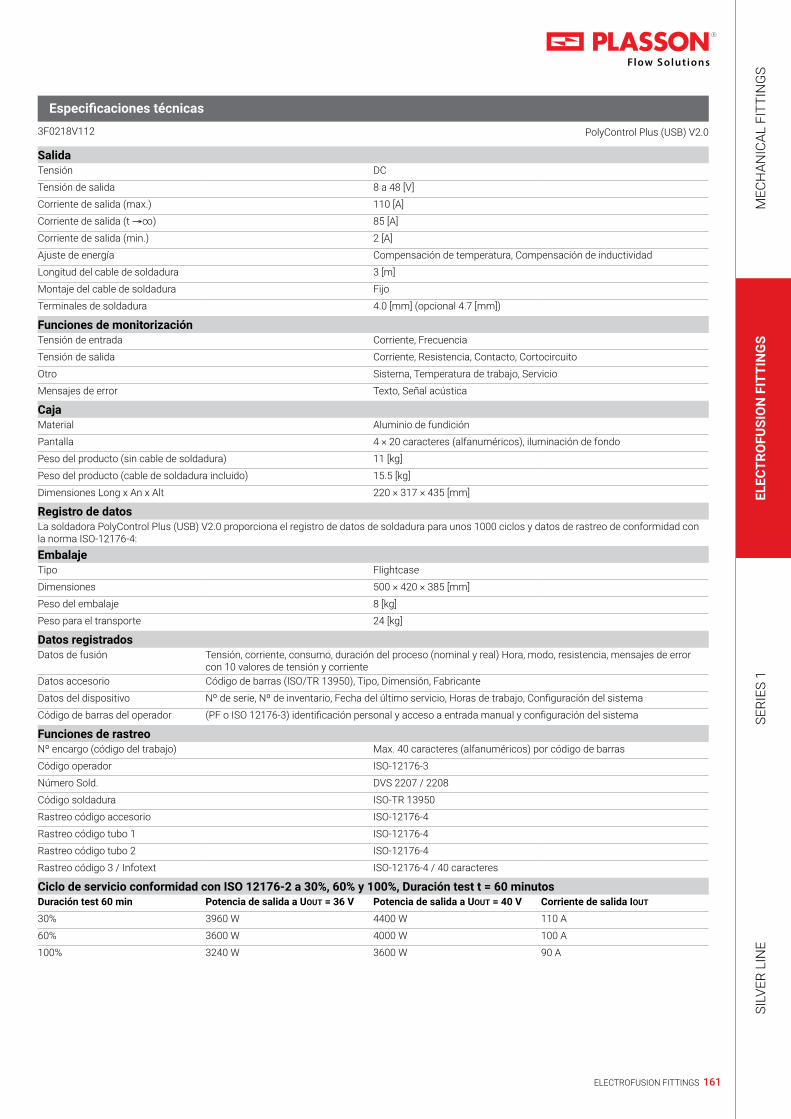
161ELECTROFUSION FITTINGS
MEC
HAN
ICAL
FIT
TIN
GS
ELEC
TRO
FUSI
ON
FIT
TIN
GS
SERI
ES 1
SILV
ER L
INE
SalidaTensión DC
Tensión de salida 8 a 48 [V]
Corriente de salida (max.) 110 [A]
Corriente de salida (t →∞) 85 [A]
Corriente de salida (min.) 2 [A]
Ajuste de energía Compensación de temperatura, Compensación de inductividad
Longitud del cable de soldadura 3 [m]
Montaje del cable de soldadura Fijo
Terminales de soldadura 4.0 [mm] (opcional 4.7 [mm])
Funciones de monitorizaciónTensión de entrada Corriente, Frecuencia
Tensión de salida Corriente, Resistencia, Contacto, Cortocircuito
Otro Sistema, Temperatura de trabajo, Servicio
Mensajes de error Texto, Señal acústica
CajaMaterial Aluminio de fundición
Pantalla 4 × 20 caracteres (alfanuméricos), iluminación de fondo
Peso del producto (sin cable de soldadura) 11 [kg]
Peso del producto (cable de soldadura incluido) 15.5 [kg]
Dimensiones Long x An x Alt 220 × 317 × 435 [mm]
Registro de datosLa soldadora PolyControl Plus (USB) V2.0 proporciona el registro de datos de soldadura para unos 1000 ciclos y datos de rastreo de conformidad con la norma ISO-12176-4:EmbalajeTipo Flightcase
Dimensiones 500 × 420 × 385 [mm]
Peso del embalaje 8 [kg]
Peso para el transporte 24 [kg]
Datos registradosDatos de fusión Tensión, corriente, consumo, duración del proceso (nominal y real) Hora, modo, resistencia, mensajes de error
con 10 valores de tensión y corrienteDatos accesorio Código de barras (ISO/TR 13950), Tipo, Dimensión, Fabricante
Datos del dispositivo Nº de serie, Nº de inventario, Fecha del último servicio, Horas de trabajo, Configuración del sistema
Código de barras del operador (PF o ISO 12176-3) identificación personal y acceso a entrada manual y configuración del sistema
Funciones de rastreoNº encargo (código del trabajo) Max. 40 caracteres (alfanuméricos) por código de barras
Código operador ISO-12176-3
Número Sold. DVS 2207 / 2208
Código soldadura ISO-TR 13950
Rastreo código accesorio ISO-12176-4
Rastreo código tubo 1 ISO-12176-4
Rastreo código tubo 2 ISO-12176-4
Rastreo código 3 / Infotext ISO-12176-4 / 40 caracteres
Ciclo de servicio conformidad con ISO 12176-2 a 30%, 60% y 100%, Duración test t = 60 minutosDuración test 60 min Potencia de salida a UOUT = 36 V Potencia de salida a UOUT = 40 V Corriente de salida IOUT
30% 3960 W 4400 W 110 A
60% 3600 W 4000 W 100 A
100% 3240 W 3600 W 90 A
3F0218V112 PolyControl Plus (USB) V2.0
Especificaciones técnicas

162 ELECTROFUSION FITTINGS
Technical catalogue 2019 | Controllers
GeneralTensión de salida 8 a 48 DC [V]
Registro de datos Sí
Potencia (60% del tiempo ON) conformidad con ISO 12176-2 2600 W (72.5 A)
Rango de temperaturas -10 a +50 [°C]
Protección IP54
Clase de aplicación 1
Conformidad con CE
Clase ISO 12176-2 - clasificación P2 4 U S1 V AK D X
Entrada de parámetros de soldaduraCódigo de barras con lector (escaneo opcional) Sí
SmartFuse/(FUSAMATIC) Sí
Entrada manual del código del accesorio Sí
Entrada manual de parámetros de soldadura Sí, UOUT: 8 a 48 V, tWELD: 0 a 9999 s
Entrada manual de parámetros de soldadura No, UOUT: 48V (prefijado), tWELD: 0 a 9999 s
Entrada/Red eléctricaTensión AC
Tensión nominal 230 [V]
Rango de tensión nominal (tolerancia) 185 a 300 [V]
Frecuencia nominal 50 [Hz]
Rango de frecuencia nominal (Tolerancia) 40 a 70 [Hz]
Factor de potencia cos ρ 0.6 a 0.9 (control de desfase)
Corriente nominal 16 [A]
Consumo eléctrico 3600 [VA]
Longitud del cable 4.5 [m]
Tipo de enchufe Euro plug
Polymatic Plus (USB + Bluetooth) 29143.0307.103
Rango de aplicaciónLas soldadoras de electrofusión del tipo Polymatic Plus (USB) están exclusivamente destinadas a la soldadura de tubos termoplásticos (o sea de PE-HD, PE80, PE100 o PP) con accesorios de menos de 48V en su voltaje de entrada.Estos dispositivos cumplen las especificaciones de las normativas DVS 2208-1 e ISO-12176-2, de las cuales derivan las normas aplicables a los equipos de electrofusión.
Rango de dimensionesEl rango de dimensiones de los accesorios para los cuales puede utilizarse una soldadora depende en primer lugar del consumo de energía de los accesorios. Dado que el consumo no es uniforme para todos los fabricantes, no es posible generalizar, y en caso de duda, es preciso examinar cada accesorio por separado. Para las soldadoras del tipo Polymatic Plus (USB), y suponiendo que todas las operaciones de soldadura se realizan en secuencia, es decir que la soldadora tiene tiempo para enfriarse mientras se prepara el accesorio siguiente, se podría emitir la siguiente declaración general:Sin limitaciones para el uso con accesorios de 20 a 630mm. Al trabajar con dimensiones a partir de los 630mm se requieren periodos más prolongados de enfriamiento, porque de otro modo podría aparecer el mensaje de error "Devicetoo hot" (Dispositivo recalentado). En tal caso será preciso dejar que el equipo se enfríe antes de volver a utilizarlo. Antes de procesar accesorios dentro de este rango de dimensiones es necesario comprobar que la demanda de corriente del accesorio no sobrepase constantemente la corriente de salida del dispositivo, y tener cuidado de no sobrepasar la corriente máxima de salida.Todo lo dicho se refiere al trabajo con una temperatura ambiente de 20°C.
3_0206_103 Polymatic Plus (USB)
Especificaciones técnicas

163ELECTROFUSION FITTINGS
MEC
HAN
ICAL
FIT
TIN
GS
ELEC
TRO
FUSI
ON
FIT
TIN
GS
SERI
ES 1
SILV
ER L
INE
SalidaTensión AC
Tensión de salida 8 a 48 [V]
Corriente de salida (max.) 110 [A]
Corriente de salida (t →∞) 40 [A]
Corriente de salida (min.) 2 [A]
Ajuste de energía Compensación de temperatura
Longitud del cable de soldadura 5 [m], otras longitudes a pedido
Montaje del cable de soldadura Fijo
Terminales de soldadura 4 [mm]
Adaptadores opcionales para terminales 4 to 4.7 [mm]
Funciones de monitorizaciónTensión de entrada Corriente, Frecuencia
Tensión de salida Corriente, Resistencia, Contacto, Cortocircuito
Otro Sistema, Temperatura de trabajo, Servicio
Mensajes de error Texto, Señal acústica
CajaMaterial Placa de acero con recubrimiento plástico
Pantalla 4 × 20 caracteres (alfanuméricos), iluminación de fondo
Peso del producto (sin cable de soldadura) 16 [kg]
Peso del producto (cable de soldadura incluido) 18 [kg]
Dimensiones Long x An x Alt 450 × 325 × 380 [mm]
Registro de datosLa soldadora Polymatic Plus (USB) proporciona el registro de datos de soldadura para 1000 ciclos.
EmbalajeTipo Flightcase
Dimensiones 500 × 420 × 385 [mm]
Peso del embalaje 8 [kg]
Peso para el transporte 24 [kg]
Datos registradosDatos generales Hora, fecha, número de informe, temperatura ambiente
Datos de fusión Tensión, corriente, consumo, duración del proceso (nominal y real), Hora, modo, resistencia, mensajes de error con 10 valores de tensión y corriente
Datos accesorio Código de barras (ISO/TR 13950), Tipo, Dimensión, Fabricante
Datos del dispositivo Nº de serie, Nº de inventario, Fecha del último servicio, Horas de trabajo, Configuración del sistema
Código operador (PF o ISO 12176-3) identificación personal y acceso a entrada manual y configuración del sistema
Funciones de rastreoCódigo Encargo y Nº (máximo 40 caracteres) ingreso por código de barras o manual
Código operador ISO-1276-3
Número Sold. DVS 2207 / 2208
Código soldadura ISO-TR 13950
Rastreo código accesorio ISO-12176-4
Rastreo código tubo 1 ISO-12176-4
Rastreo código tubo 2 ISO-12176-4
Rastreo código 3 / Infotext ISO-12176-4 / 40 caracteres
Ciclo de servicio conformidad con ISO 12176-2 a 30%, 60% y 100%, Duración test t = 60 minutosDuración test 60 min Potencia de salida a UOUT = 36 V Potencia de salida a UOUT = 40 V Corriente de salida IOUT
30% 3500 W 3900 W 97.3 A
60% 2600 W 2900 W 72.5 A
100% 2100 W 2350 W 58.4 A
3_0206_103 Polymatic Plus (USB)
Especificaciones técnicas

164 ELECTROFUSION FITTINGS
Technical catalogue 2019 | Controllers
GeneralTensión de salida 8 a 48 DC
Registro de datos Sí
Potencia (60% del tiempo ON) conformidad con ISO 12176-2 2050 W (55.9 A)
Rango de temperaturas -10 a +50 [°C]
Protección IP54
Clase de aplicación 1
Conformidad con CE
Clase ISO 12176-2 - clasificación P2 3 U S1 V AK D X
Entrada de parámetros de soldaduraCódigo de barras con lector (escaneo opcional) Sí
SmartFuse/(FUSAMATIC) Sí
Entrada manual del código del accesorio Sí
Entrada manual de parámetros de soldadura Sí, UOUT: 8 a 48 V, tWELD: 0 a 9999 s
Entrada manual de parámetros de soldadura No, UOUT: 48V (prefijado), tWELD: 0 a 9999 s
Entrada/Red eléctricaTensión AC
Tensión nominal 230 [V]
Rango de tensión nominal (tolerancia) 185 a 300 [V]
Frecuencia nominal 50 [Hz]
Rango de frecuencia nominal (Tolerancia) 40 a 70 [Hz]
Factor de potencia cos ρ 0.6 a 0.9 (control de desfase)
Corriente nominal 16 [A]
Consumo eléctrico 3200 [VA]
Longitud del cable 5 [m]
Tipo de enchufe Euro plug
Tiny Data MF (USB + Bluetooth) 29143.0308T108
Rango de aplicaciónLas soldadoras de electrofusión del tipo Tiny MF (USB) están exclusivamente destinadas a la soldadura de tubos termoplásticos (o sea de PE-HD, PE80, PE100 o PP) con accesorios de menos de 48V en su voltaje de entrada.Estos dispositivos cumplen las especificaciones de las normativas DVS 2208-1 e ISO-12176-2, de las cuales derivan las normas aplicables a los equipos de electrofusión.
Rango de dimensionesEl rango de dimensiones de los accesorios para los cuales puede utilizarse una soldadora depende en primer lugar del consumo de energía de los accesorios. Dado que el consumo no es uniforme para todos los fabricantes, no es posible generalizar, y en caso de duda, es preciso examinar cada accesorio por separado. Para las soldadoras del tipo Tiny MF (USB), y suponiendo que todas las operaciones de soldadura se realizan en secuencia, es decir que la soldadora tiene tiempo para enfriarse mientras se prepara el accesorio siguiente, se podría emitir la siguiente declaración general:Sin limitaciones para el uso con accesorios de 20 a 355mm. Al trabajar con dimensiones a partir de los 400mm se requieren periodos más prolongados de enfriamiento, porque de otro modo podría aparecer el mensaje de error "Devicetoo hot" (Dispositivo recalentado). En tal caso será preciso dejar que el equipo se enfríe antes de volver a utilizarlo. Antes de procesar accesorios dentro de este rango de dimensiones es necesario comprobar que la demanda de corriente del accesorio no sobrepase constantemente la corriente de salida del dispositivo, y tener cuidado de no sobrepasar la corriente máxima de salida.Todo lo dicho se refiere al trabajo con una temperatura ambiente de 20°C.
3_0208T108 Tiny Data MF (USB)
Especificaciones técnicas

165ELECTROFUSION FITTINGS
MEC
HAN
ICAL
FIT
TIN
GS
ELEC
TRO
FUSI
ON
FIT
TIN
GS
SERI
ES 1
SILV
ER L
INE
SalidaTensión AC
Tensión de salida 8 a 48 [V]
Corriente de salida (max.) 110 [A]
Corriente de salida (t →∞) 30 [A]
Corriente de salida (min.) 2 [A]
Ajuste de energía Compensación de temperatura
Longitud del cable de soldadura 4 [m], otras longitudes a pedido
Montaje del cable de soldadura Fijo
Terminales de soldadura 4.0 [mm] (opcional 4.7 [mm])
Funciones de monitorizaciónTensión de entrada Corriente, Frecuencia
Tensión de salida Corriente, Resistencia, Contacto, Cortocircuito
Otro Sistema, Temperatura de trabajo, Servicio
Mensajes de error Texto, Señal acústica
CajaMaterial Placa de acero
Pantalla 4 × 20 caracteres (alfanuméricos), iluminación de fondo
Peso del producto (sin cable de soldadura) 14 [kg]
Peso del producto (cable de soldadura incluido) 16.5 [kg]
Dimensiones Long x An x Alt 325 × 275 × 290 [mm]
Registro de datosLa soldadora Tiny Data MF (USB) proporciona el registro de datos de soldadura para unos 1000 ciclos.
EmbalajeTipo Flightcase
Dimensiones 500 × 420 × 385 [mm]
Peso del embalaje 8 [kg]
Peso para el transporte 24 [kg]
Datos registradosDatos generales Hora, fecha, número de informe, temperatura ambiente
Datos de fusión Tensión, corriente, consumo, duración del proceso (nominal y real), Hora, modo, resistencia, mensajes de error con 10 valores de tensión y corriente
Datos accesorio Código de barras (ISO/TR 13950), Tipo, Dimensión, Fabricante
Datos del dispositivo Nº de serie, Nº de inventario, Fecha del último servicio, Horas de trabajo, Configuración del sistema
Código operador (PF o ISO 12176-3) identificación personal y acceso a la configuración del sistema
Funciones de rastreoCódigo Encargo y Nº (máximo 40 caracteres) ingreso por código de barras o manual
Código operador ISO-1276-3
Número Sold. DVS 2207 / 2208
Código soldadura ISO-TR 13950
Rastreo código accesorio ISO-12176-4
Rastreo código tubo 1 ISO-12176-4
Rastreo código tubo 2 ISO-12176-4
Rastreo código 3 / Infotext ISO-12176-4 / 40 caracteres
Ciclo de servicio conformidad con ISO 12176-2 a 30%, 60% y 100%, Duración test t = 60 minutosDuración test 60 min Potencia de salida a UOUT = 36 V Potencia de salida a UOUT = 40 V Corriente de salida IOUT
30% 2700 W 3000 W 74.1 A
60% 2050 W 2250 W 55.9 A
100% 1600 W 1800 W 44.7 A
3_0208T108 Tiny Data MF (USB)
Especificaciones técnicas

166 ELECTROFUSION FITTINGS
Technical catalogue 2019 | Controllers
GeneralTensión de salida 40 AC [V]
Registro de datos Sí
Potencia (60% del tiempo ON) conformidad con ISO 12176-2 2050 W (55.9 A)
Rango de temperaturas -10 a +50 [°C]
Protección IP54
Clase de aplicación 1
Conformidad con CE
Clase ISO 12176-2 - clasificación P2 3 U S1 F A D M
Entrada de parámetros de soldaduraCódigo de barras con lector (escaneo opcional) No
SmartFuse/(FUSAMATIC) Sí
Entrada manual del código del accesorio No
Entrada manual de parámetros de soldadura No, UOUT: 8 a 48 V, tWELD: 0 a 9999 s
Entrada manual de parámetros de soldadura No, UOUT: 48V (prefijado), tWELD: 0 a 9999 s
Entrada/Red eléctricaTensión AC
Tensión nominal 230 [V]
Rango de tensión nominal (tolerancia) 185 a 300 [V]
Frecuencia nominal 50 [Hz]
Rango de frecuencia nominal (Tolerancia) 40 a 70 [Hz]
Factor de potencia cos ρ 0.6 a 0.9 (control de desfase)
Corriente nominal 16 [A]
Consumo eléctrico 3600 [VA]
Longitud del cable 4.5 [m]
Tipo de enchufe Euro plug
Monomatic Data (USB + Bluetooth) 29143.0307.000
Soldadora automática SmartFuseRango de aplicaciónLas soldadoras de electrofusión del tipo Monomatic Data (USB) están exclusivamente destinadas a la soldadura de tubos termoplásticos (o sea de PE-HD, PE80, PE100 o PP) con accesorios de menos de 48V en su voltaje de entrada.Estos dispositivos cumplen las especificaciones de las normativas DVS 2208-1 e ISO-12176-2, de las cuales derivan las normas aplicables a los equipos de electrofusión.
Rango de dimensionesEl rango de dimensiones de los accesorios para los cuales puede utilizarse una soldadora depende en primer lugar del consumo de energía de los accesorios. Dado que el consumo no es uniforme para todos los fabricantes, no es posible generalizar, y en caso de duda, es preciso examinar cada accesorio por separado. Para las soldadoras del tipo Monomatic Data (USB), y suponiendo que todas las operaciones de soldadura se realizan en secuencia, es decir que la soldadora tiene tiempo para enfriarse mientras se prepara el accesorio siguiente, se podría emitir la siguiente declaración general:Sin limitaciones para el uso con accesorios de 20 a 355mm. Al trabajar con dimensiones a partir de los 400mm se requieren periodos más prolongados de enfriamiento, porque de otro modo podría aparecer el mensaje de error "Devicetoo hot" (Dispositivo recalentado). En tal caso será preciso dejar que el equipo se enfríe antes de volver a utilizarlo. Antes de procesar accesorios dentro de este rango de dimensiones es necesario comprobar que la demanda de corriente del accesorio no sobrepase constantemente la corriente de salida del dispositivo, y tener cuidado de no sobrepasar la corriente máxima de salida.Todo lo dicho se refiere al trabajo con una temperatura ambiente de 20°C.
3_0206_000 Monomatic Data (USB)
Especificaciones técnicas

167ELECTROFUSION FITTINGS
MEC
HAN
ICAL
FIT
TIN
GS
ELEC
TRO
FUSI
ON
FIT
TIN
GS
SERI
ES 1
SILV
ER L
INE
SalidaTensión AC
Tensión de salida 40 [V]
Corriente de salida (max.) 110 [A]
Corriente de salida (t →∞) 30 [A]
Corriente de salida (min.) 2 [A]
Ajuste de energía Ninguno
Longitud del cable de soldadura 5 [m], otras longitudes a pedido
Montaje del cable de soldadura Fijo
Terminales de soldadura 4.0 [mm] (opcional 4.7 [mm])
Funciones de monitorizaciónTensión de entrada Corriente, Frecuencia
Tensión de salida Corriente, Resistencia, Contacto, Cortocircuito
Otro Otro sistema, Temperatura de trabajo, Servicio
Mensajes de error Texto, Señal acústica
CajaMaterial Placa de acero con recubrimiento plástico
Pantalla 4 × 20 caracteres (alfanuméricos), iluminación de fondo
Peso del producto (sin cable de soldadura) 16 [kg]
Peso del producto (cable de soldadura incluido) 18 [kg]
Dimensiones Long x An x Alt 450 × 325 × 380 [mm]
Registro de datosLa soldadora Monomatic Data (USB) proporciona el registro de datos de soldadura para 250 ciclos.
EmbalajeTipo Flightcase
Dimensiones 500 × 420 × 385 [mm]
Peso del embalaje 8 [kg]
Peso para el transporte 24 [kg]
Datos registradosDatos generales Hora, fecha, número de informe, temperatura ambiente
Datos de fusión Tensión, corriente, consumo, duración del proceso (nominal y real), Hora, modo, resistencia, mensajes de error con 10 valores de tensión y corriente
Datos del dispositivo Nº de serie, Nº de inventario, Fecha del último servicio Horas de trabajo, Configuración del sistema
Ciclo de servicio conformidad con ISO 12176-2 a 30%, 60% y 100%, duración test t = 60 minutosDuración test 60 min Potencia de salida a UOUT = 36 V Potencia de salida a UOUT = 40 V Corriente de salida IOUT
30% 2700 W 3000 W 74.1 A
60% 2050 W 2250 W 55.9 A
100% 1600 W 1800 W 44.7 A
3_0206_000 Monomatic Data (USB)
Especificaciones técnicas

168 ELECTROFUSION FITTINGS
Technical catalogue 2019 | Installation Tools
Extension Key for Tapping Valve
Hand Scrapers
Rotational Scraper Tools
Key for Tapping Saddle
Llave de Extensión para Toma de Servicio Con Válvula
Raspatubos Manual
Raspatubos Giratorios
Llave para Toma de Servicio
49546010 | 0.8 - 1.1mm49546020 | 1.0 - 1.4mm49546030 | 1.2 - 1.8mm
29145.3002.001 | 1.1/2”29145.3002.003 | 2.1/2”
29144.4200.001 | 20-63mm29144.4200.031 | 20-125mm29144.4200.032 | 63-225mm29144.4200.033 | 90-315mm
29170160 | 50-160mm29170315 | 75-315mm29170710 | 355-710mm
29144.4200.009 | 250-800mm
29202000 | 18cm

169ELECTROFUSION FITTINGS
MEC
HAN
ICAL
FIT
TIN
GS
ELEC
TRO
FUSI
ON
FIT
TIN
GS
SERI
ES 1
SILV
ER L
INE
Rotational Pipe Cutter (S-Type)Cortador de TuberÍa Giratorio (Tipo S)
29145.3001.004 | 20-75mm29145.3001.001 | 50-140mm29145.3001.002 | 90-160mm
Pipe CutterCortadores de Tuberia
29145.3000.005 | 42mm
29145.3000.007 | 63mm, One-Hand Operaion
29145.3000.001 | 63mm
Plasson Scraper Tool for Pipe Ends
Rotational Pipe Cutters
Raspatubos Giratorio Plasson
Cortador de TuberÍa Giratorio
29144.4200.015 | 63-200mm29144.4200.027 | 90-315mm29144.4200.016 | 180-400mm2912450800 | 450-800mm
29144.4400.006 | 32-125mm29144.4400.004 | 63-200mm29144.4400.005 | 90-315mm

170 ELECTROFUSION FITTINGS
Technical catalogue 2019 | Installation Tools
Pipe Clamping Tools
Squeeze - Off Tools
Herramientas de Sujeción de Tubos
Prensatubos
29144.4300.006 | 20-63mm
29144.4100.010 | 63mm SDR11, , SDR1729144.4100.003 | 75-200mm
29144.4300.021 | 250-630mm
29144.4300.001 | 32-110mm29144.4300.002 | 110-225mm
29363180 | 63-180mm29363110 | 63-110mm

171ELECTROFUSION FITTINGS
MEC
HAN
ICAL
FIT
TIN
GS
ELEC
TRO
FUSI
ON
FIT
TIN
GS
SERI
ES 1
SILV
ER L
INE
DetergentsDetergentes
29145.2000.001 | Tangit Detergent, 1 Liter
29145.2000.002 | 100 Cleaning Pads with Tangit
Pipe Clamping ToolsHerramientas de Sujeción de Tubos
29145.3006.063 | 63mm29145.3006.075 | 75mm29145.3006.090 | 90mm29145.3006.110 | 110mm29145.3006.125 | 125mm29145.3006.160 | 160mm29145.3006.180 | 180mm29145.3006.200 | 200mm29145.3006.225 | 225mm29600250 | 250mm
MarkersMarcadores
29145.3100.019 | Plasson Marking Pen, Silver, 10 pcs29600003 | Plasson Marking Pen, Silver, 10 pcs

172 ELECTROFUSION FITTINGS
Technical catalogue 2019 | Installation Tools
Rounding Tool
Tools for Wastewater Saddles (See Pages 138, 139)
Redondeador hidráulico
Herramientas para enlaces para aguas residuales (ver páginas 138 y 139)
29144.4702.000 | Rounding Tool 450-800 Hydraulic Redondeador hidráulico 450-800
29144.4700.001 | Drilling And Clamping Tools (set) for Wastewater Branch Saddle 160mm Juego de herramientas de perforación y sujeción para collarines de derivación para aguas residuales 160mm
29144.4703.001 | Cutting and Clamping Tools for 45º Wastewater Saddle 110mm Herramientas de corte y sujeción para collarines de 45º para aguas residuales 110mm

173ELECTROFUSION FITTINGS
MEC
HAN
ICAL
FIT
TIN
GS
ELEC
TRO
FUSI
ON
FIT
TIN
GS
SERI
ES 1
SILV
ER L
INE
Rotational Scraper Tools
Electrical Saddle Scraper
Core Drill Kit for Plasson-Saddle Outlet
Drilling Machine
Pressure Test Pump
Rascador giratorio para tuberías de PEAD
Rascador eléctrico para tuberías de PEAD
29144.4200.009 | 250-800mm29144.4200.012 | 800-1200mm
29144.4200.024 | 230V (Electrical Scraper)
29144.4702.999 | Drilling machine (Metabo BE75-X3/230V) with modified 225Nm gear including hexagon bit and adapter for core cutter for use up to 250mm
29144.4701.005 | Pressure test pump with adapter for plasson large bore saddles
29144.4702.002 | 2”female, 3”ips/ 4”ips/ 4”dips with sds-max-adapter+suitcase+ pilot drill, sds plus

174 ELECTROFUSION FITTINGS
Technical catalogue 2019 | Installation Tools
Hot Tapping Tool
Saddle Pressing Tool
Saddle Clamping Tool
29144.4705.001 | Hot tapping tool ISO Flange DN150 with 230V motor
29142.4701.066 | Pressing tool 225mm/SDR17 for LightFit Saddle
29142.4701.226 | Clamping plate 225mm/SDR17 splitable, for LightFit Saddle, PLASSON
Saddle Clamping Tool
29144.4701.315 | Saddle clamp 250-800mm splitable; Outlet 315mm; PLASSON; incl. pressing tool in suitcase

175ELECTROFUSION FITTINGS
MEC
HAN
ICAL
FIT
TIN
GS
ELEC
TRO
FUSI
ON
FIT
TIN
GS
SERI
ES 1
SILV
ER L
INE
29144.4701.003 | Split-able saddle clamp – complete kit including re-rounder, straps, ratchets, test tube cutter, clamping plates for outlets: 2" threaded transition/90/flange DN80, 110, 125/ flange DN100, 160/flange DN150 Juego completo de barras sujetadoras con bisagras incluye redondeador, 2 cinchas, 2 cremalleras de amarre, cortador de tubo de prueba de presión, plancha de barras sujetadores para collarines de salidas: 2" transición roscada, 90mm, 110mm, 125mm, 160mm y salidas bridadas respectivamente
29144.4701.004 | Large bore splitable saddle clamp 10 ips a 32 ips/ complete kit include outlets 3”ips, 4”ips y 4”dips
* Must be used in combination with tensioning tools set 29144.4701.009
29144.4701.009 | Tensioning tools set for large branch saddles, outlets 180 to 400, including 3 straps, 3 ratchets, torque wrench Juego completo de cinchas de amarre, cremalleras y tensión para collarines de derivación con salidas desde 180mm a 400mm, incluye: 3 cinchas, 3 cremalleras de amarre y llave de torque
29144.4701.250* | Split-able clamping plate for outlet 250/flange DN 250, including- re-rounding shell Juego completo de barras sujetadoras con bisagras para salidas de 250mm y bridado. Incluye redondeador metálico para la salida 250mm
29144.4701.400* | Split-able clamping plate for outlet 400/flange DN 400, including adaptor for center strap Juego completo de barras sujetadoras con bisagras para salidas de 400mm y bridado. Incluye cincha redondeadora y centralizadora para la salida 400mm y bridado
Saddle Pressing and Clamping ToolsHerramientas necesarias para la instalación de Collarines de derivación y transición de gran diámetro

176 ELECTROFUSION FITTINGS
Technical catalogue 2019 | Installation Tools
29144.4702.003 | Core cutters set including: SDS max core, SDS plus core, 13mm core, center pilot drill, cutters for outlets: 2" threaded transition, 90/flange DN80, 110, 125/ flange DN100, 160/flange DN150 Juego de brocas campana de corte. Incluye: SDS max core, SDS plus core, 13mm core, center pilot drill, Brocas para corte y perforación de salidas: broca 2" transición roscada, brocas campana para 90mm, 110mm, 125mm, 160mm y bridadas respectivamente
Core cutters- for each outlet size
Clamping Tool for Sensor Adaptor
Brocas campana para cada diámetro
29144.4702.199 | Core cutter for outlet 250/ flange DN 250 Broca campana para salida 250/ bridado DN 250
29142.4704.196 | Core cutter for PLASSON-Saddle outlet 225mm/SDR17; borehole: 196mm c/w SDS-MAX adapter
29142.4702.251 | Core cutter for PLASSON-Saddle outlet 315mm/SDR11; borehole: 251mm c/w SDS-MAX adapter, center drill and transport box
29144.4702.319 | Core cutter for outlet 400/ flange DN 400 Broca campana para salida 400/ bridado DN 400
29144.4706.000 | 110-1200mm29144.4706.001 | 110-1200mm (version without strap)

177ELECTROFUSION FITTINGS
MEC
HAN
ICAL
FIT
TIN
GS
ELEC
TRO
FUSI
ON
FIT
TIN
GS
SERI
ES 1
SILV
ER L
INE
Minimum required Generator Output powerPotencia mínima requerida de un generador de energía eléctrica, Potencia de salida
Voltage- 240 V, frequency- 50Hz, 1 phaseSynchronized, recommended - Mechanically regulated.
Fitting size Output powerMechanically controlled generator
Output powerElectronically controlled generator
20-75mm 2.0 KVA 2.0 KVA
90-160mm 3.2 KVA 3.2 KVA
180-500mm 4.5 KVA 5.0 KVA
500mm and up 6.5 KVA 7.5 KVA
When operating at high altitudes, rated generator power drops 10% for each 1000 meters. Use larger generator accordingly.
Sea level 1000m 2000m 3000m
3.2 KVA 3.5 KVA 4.0 KVA 4.2 KVA
4.5 KVA 5.0 KVA 5.5 KVA 6.5 KVA
6.5 KVA 7.5 KVA 8.0 KVA 8.5 KVA
Voltaje- 240 V, frecuencia- 50Hz, 1 faseGenerador sincronizado, recomendablemente de regulación mecánica.
Diámetro de accesorios Potencia de salida de regulación mecánica
Potencia de salida de regulación electrónica
20-75mm 2.0 KVA 2.0 KVA
90-160mm 3.2 KVA 3.2 KVA
180-500mm 4.5 KVA 5.0 KVA
500mm and up 6.5 KVA 7.5 KVA
Cuando trabaje en zonas altas o elevadas considere una caída de potencia del generador del orden del 10% cada 1,000 metros de altura. Calcular la potencia necesaria acorde a la altura en la que se llevara a cabo la obra.
Potencia: Reducción de potencia aproximada = 10% cada 1,000 metros sobre el nivel del mar. El operador debe considerar la potencia necesaria del generador de acuerdo a la altitud sobre el nivel del mar en la que va a trabajar.
Características de un generador a combustible:En Plasson para el uso con máquinas de electrofusión consideramos optimo min. 5.5kW para uso a nivel del mar.1,000 mts. sobre el nivel del mar : min 6.1kW2,000 mts. sobre el nivel del mar : min 6.9kW2,800 mts. sobre el nivel del mar : min. 7.6kW3,000 mts. sobre el nivel del mar : min. 7.9kWPower (on altitude) = 5.5kW / (1 - (altitude / 10000m)).

178 ELECTROFUSION FITTINGS
Technical catalogue 2019 | Generator Output Power
Extension power cable sizeCable alargador de alimentación
Cable length Minimum cross-section
Up to 20 meters 1.5mm²
20-50 meters 2.5mm²
50-100 meters 4.0mm²
Largo del cable Grosor mínimo
Hasta 20 metros 1.5mm²
20-50 metros 2.5mm²
50-100 metros 4.0mm²

179ELECTROFUSION FITTINGS
MEC
HAN
ICAL
FIT
TIN
GS
ELEC
TRO
FUSI
ON
FIT
TIN
GS
SERI
ES 1
SILV
ER L
INE

180 ELECTROFUSION FITTINGS

181ELECTROFUSION FITTINGS
MEC
HAN
ICAL
FIT
TIN
GS
ELEC
TRO
FUSI
ON
FIT
TIN
GS
SERI
ES 1
SILV
ER L
INE


184 SERIES 1
Technical catalogue 2019 | Series 1

185SERIES 1
MEC
HAN
ICAL
FIT
TIN
GS
ELEC
TRO
FUSI
ON
FIT
TIN
GS
SERI
ES 1
SILV
ER L
INE

186
Plasson Series 1
Plasson Series 1 - The new range of innovative fittings created by Plasson, market leader in
design and manufacture of reliable fittings for polyethylene pipe systems.
Plasson Series 1 - Fittings provide dedicated solutions for connecting PE pipe to various other
pipe materials, such as Copper, Polybutylene, PVC and PEX.
Plasson Series 1 - Push fittings are designed to withstand 16 bar pressure rating. Inserting the
pipe up to the fitting stop creates both the seal and the grip on the pipe.
Plasson Series 1 - Compact and attractive design makes this fitting ideal for the plumbing
market, where space is limited and appearance is crucial. Simplicity of assembly makes both the
professional and occasional user’s job easier while retaining the Plasson reliability.
The combination of Plasson’s current fitting range and the new Series 1 fulfill the requirements
of all markets for PE pipe connections and connections to other pipe materials.
• Aesthetically designed product - gives a professional finish to the job
• Assembly tools not required - simple push fit assembly
• Compact size - can be assembled in confined spaces
• Instant seal and integrity of joint - captive seal and no nuts to tighten
• Full end load performance - no need to restrain joints
• Transition from PE to internal plumbing systems - Copper, PB, PVC and PEX
accommodated in one fitting
• 50 year design life - provides total reliability
• Tamper resistant design - ensures system integrity
• Reduced stock shelf space
Plasson Series 1 features and benefits include:

187SERIES 1
MEC
HAN
ICAL
FIT
TIN
GS
ELEC
TRO
FUSI
ON
FIT
TIN
GS
SERI
ES 1
SILV
ER L
INE
Threads
All threads conform to ISO - 7/1, BS 21,
DIN 2999, NEN 3258, AS 1722 Part 1.
All external threads are tapered.
All internal threads are parallel.
Legend
UB Units par bag
UC Units per carton
W Weight in grams
The units per bag in this catalogue are the default figures,
other figures might be applicable to certain markets.
Note
Before installation, ensure that the end of the pipe to be
inserted into the fitting is free of scratches and other
imperfections and that both the pipe and the fitting itself are
free of sand, mud, stones, etc. If fittings are reused, ensure
that split ring and grip ring teeth are sharp and bite into the
pipe, to avoid pullouts. If uncertain, replace the split ring and
grip ring.
Pull out resistance of PVC Adaptors and Universal Adaptors
has been approved by pressure testing UPVC/PP pipe
assemblies at 25 bar operating pressure for at least 1 hour.
Note: We strongly recommend the use of PTFE tape in
threaded connections.
For diameters 40mm and above, chamfering and lubrication
of the pipe end will ease insertion
(use silicone lubricant).
Technical Specifications
Materials
Compression FittingsBody: Polypropylene, high grade copolymer
Nut: High Grade Polypropylene
Split Ring and Grip Ring: Acetal (POM)
Liner: Acetal (POM)
Seal: Nitrile rubber (NBR)
Reinforcing Ring: Stainless steel on all female offtakes from
1¼” up to 2”
Threaded FittingsBody: Polypropylene, high grade copolymer
Reinforcing Ring: Stainless steel
Brass Threads: CW617
Operating Temperatures
The fittings are not to be used with hot water, although they
withstand the same temperature as the polyethylene pipe
itself.
The fittings will withstand sub-zero temperatures.
Chemical Resistance
Plasson fittings are supplied, as standard, with polyacetal
split and grip rings and NBR seals which are suitable for
water.
Operating Pressures and Quality Certificates
Plasson fittings sizes 20-63 are tested and approved for
water according to ISO 17885 (replaced 14236) to PN16.

188 SERIES 1
Technical catalogue 2019 | Series 1
1001
Page 192 Coupler
17610
Page 192 Universal Slip Repair Coupler
07990
Page 192 Plasson WrenchLlave Plasson
17610/1761Q
Page 193 Slip Repair Coupler
1011
Page 193 Reducing Coupler
1012
Page 193 End Plug
1002
Page 194 Male Adaptor
1003
Page 194 Female Adaptor
1003G
Page 195 Female Adaptor G Thread
1001C
Page 195 Copper Pipe Adaptor
1002C
Page 195 Copper Pipe Male Adaptor
1003C
Page 196 Female Copper Adaptor
10017
Page 196 Universal Adaptor
1001Q
Page 196 PE to PVC Pipe Adaptor
1001QQ
Page 197 Coupling for PVC Pipe
1001M
Page 197 Coupler Metric to Imperial
1072
Page 198 Male Adaptor with Threaded Brass Offtake
1073
Page 199 Female Adaptor with Threaded Brass Offtake
Plasson Series 1

189SERIES 1
MEC
HAN
ICAL
FIT
TIN
GS
ELEC
TRO
FUSI
ON
FIT
TIN
GS
SERI
ES 1
SILV
ER L
INE
1073G
Page 199 Female Adaptor with Threaded G* Brass Offtake
1004
Page 200 90° Tee
1034
Page 200 90° Reducing Tee
1014
Page 201 90º Tee with Threaded Female Offtake
1005
Page 201 90° Elbow
1006
Page 202 45° Elbow
1075
Page 202 Wall Plate Elbow
1051
Page 203 90° Reducing Elbow
1005M
Page 203 90° Elbow Metric to Imperial
1085
Page 204 90° Elbow with Threaded Male Offtake
1015
Page 204 90° Elbow with Threaded Female Offtake
1077
Page 205 90° Elbow with Threaded Brass Male Offtake
1076
Page 205 90° Elbow with Threaded Brass Female Offtake
03410
Page 206 Compression Stoptap
0341C
Page 206 Stoptap - Copper Pipe Adaptor
0358916
Page 206 Free Nut Union for Water Meter
0358917
Page 207 Free Nut Adaptor with Check Valve
10990
Page 207 Plasson Series 1 Wrench

190 SERIES 1
Technical catalogue 2019 | Series 1
18960
Page 207 Chamfer Tool for PE PipesHerramienta para biselar
10004
Page 208 Nut
10002
Page 208 NBR O-Ring
10002D
Page 208 EPDM O-Ring
100029
Page 209 NBR Shaped Seal
10002D
Page 209 EPDM Shaped Seal
10003
Page 209 Split Ring
10008
Page 210 Grip Ring
1091Q
Page 210 PVC Pipe Adaptor Kit
Page 211 Installation Instructions
Page 211 Disassembly
Page 212 Assembly Instructions PVC Pipe Kit
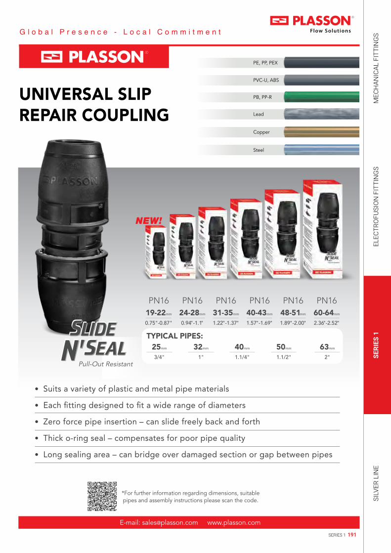
191SERIES 1
MEC
HAN
ICAL
FIT
TIN
GS
ELEC
TRO
FUSI
ON
FIT
TIN
GS
SERI
ES 1
SILV
ER L
INE
Copper
Lead
PB, PP-R
PVC-U, ABS
PE, PP, PEX
Steel
UNIVERSAL SLIPREPAIR COUPLING
E-mail: [email protected] www.plasson.com
25mm
3/4"
TYPICAL PIPES:32mm
1"
40mm
1.1/4"
50mm
1.1/2"
63mm
2"Pull-Out Resistant
• Suits a variety of plastic and metal pipe materials
• Each fitting designed to fit a wide range of diameters
• Zero force pipe insertion – can slide freely back and forth
• Thick o-ring seal – compensates for poor pipe quality
• Long sealing area – can bridge over damaged section or gap between pipes
*For further information regarding dimensions, suitable pipes and assembly instructions please scan the code.
PN1619-22mm
0.75"-0.87"
PN1624-28mm
0.94"-1.1"
PN1631-35mm
1.22"-1.37"
PN1640-43mm
1.57"-1.69"
PN1648-51mm
1.89"-2.00"
PN1660-64mm
2.36"-2.52"
NEW!

192 SERIES 1
Technical catalogue 2019 | Series 1
Coupler 1001
Ed
l
H
Product Code Size d E H l UB UC W
100100020 20 41 92 45 1 260 64100100025 25 47 98 48 1 200 80100100032 32 58 108 53 1 120 126100100040 40 70 142 70 1 90 256100100050 50 85 158 78 1 55 369100100063 63 103 183 90 1 30 620
Universal Slip Repair Coupler NEW! 17610
Ed
l
H
Product Code Size d E H l UB UC W
176100019022 19-22 58 180 119 — — —176100024028 24-28 66 200 133 1 56 345176100031035 31-35 76 210 143 1 40 467176100040043 40-43 89 250 151 1 30 717176100048051 48-51 101 270 158 1 20 968176100060064 60-64 120 310 176 1 10 1517
Plasson Wrench 07990
Llave Plasson
Product Code Size UB UC W
07990001 16 - 40 — 250 6507990005 40 - 75 — 75 296

193SERIES 1
MEC
HAN
ICAL
FIT
TIN
GS
ELEC
TRO
FUSI
ON
FIT
TIN
GS
SERI
ES 1
SILV
ER L
INE
Slip Repair Coupler 17610/1761Q*
Ed
l
H
Product Code Size d E H l UB UC W
1761Q0025 25 60 150 94 1 100 1821761Q0032 32 68 160 96 1 80 238
* Split ring with metal teeth for wide range of plastic pipes
Reducing Coupler 1011
EE1 dd1
ll1
H
Product Code Size d x d1 E H l l1 E1 UB UC W
101100025020 25 x 20 47 100 48 45 41 1 200 75101100032020 32 x 20 58 106 54 45 41 1 160 95101100032025 32 x 25 58 110 54 48 47 1 160 109101100040032 40 x 32 70 139 71 55 58 1 100 196101100050025 50 x 25 85 151 79 46 47 1 80 262101100050032 50 x 32 85 151 79 55 58 1 75 285101100050040 50 x 40 85 165 77 53 58 1 65 326101100063032 63 x 32 103 170 91 55 58 1 45 446101100063040 63 x 40 103 184 91 72 70 1 40 485101100063050 63 x 50 103 187 91 81 85 1 35 542
End Plug 1012
Ed
l
H
Product Code Size d E H l UB UC W
101200020 20 41 56 45 1 360 39101200025 25 47 60 48 1 300 50101200032 32 58 68 53 1 220 82101200040 40 70 90 71 1 150 146101200050 50 85 102 79 1 100 229101200063 63 103 117 91 1 55 379

194 SERIES 1
Technical catalogue 2019 | Series 1
Male Adaptor 1002
EdR
ll2
H
Product Code Size d x R E H l l2 UB UC W
100200020005 20 x ½” 41 70 45 16 1 340 41100200020007 20 x ¾” 41 71 45 17 1 300 41100200025005 25 x ½” 47 75 48 16 1 300 52100200025007 25 x ¾” 47 76 48 17 1 280 52100200025010 25 x 1” 47 78 48 19 1 260 55100200032007 32 x ¾” 58 82 55 17 1 200 83100200032010 32 x 1” 58 84 55 19 1 200 86100200032013 32 x 1¼” 58 86 55 21 1 200 90100200032015 32 x 1½” 58 86 55 21 1 200 94100200032020 32 x 2” 58 97 55 25 1 140 138100200040010 40 x 1” 70 104 73 19 1 140 145100200040013 40 x 1¼” 70 106 73 21 1 135 149100200040015 40 x 1½” 70 106 73 21 1 130 152100200040020 40 x 2” 70 110 73 25 1 130 161100200050010 50 x 1” 85 125 78 19 1 90 238100200050013 50 x 1¼” 85 122 78 21 1 90 231100200050015 50 x 1½” 85 114 81 21 1 90 226100200050020 50 x 2” 85 118 81 25 1 85 232100200063015 63 x 1½” 103 125 92 19 1 50 377100200063020 63 x 2” 103 129 92 25 1 50 367
Female Adaptor 1003EdRp
ll2
H
Product Code Size d x Rp E H l l2 UB UC W
100300020005 20 x ½” 41 67 45 17 1 340 43100300020007 20 x ¾” 41 71 45 18 1 320 45100300025005 25 x ½” 47 70 48 17 1 300 52100300025007 25 x ¾” 47 71 48 18 1 280 52100300025010 25 x 1” 47 80 48 21 1 280 60100300032007 32 x ¾” 58 77 54 18 1 200 78100300032010 32 x 1” 58 79 54 21 1 200 81100300032013 32 x 1¼” 58 90 54 24 1 160 112100300040010 40 x 1” 70 97 70 21 1 140 153100300040013 40 x 1¼” 70 100 70 24 1 135 171100300040015 40 x 1½” 70 103 70 24 1 130 171100300050013 50 x 1¼” 85 110 78 24 1 90 241100300050015 50 x 1½” 85 110 78 24 1 90 247100300050020 50 x 2” 85 118 78 29 1 80 252100300063015 63 x 1½” 103 125 90 24 1 50 378100300063020 63 x 2” 103 129 90 29 1 45 379

195SERIES 1
MEC
HAN
ICAL
FIT
TIN
GS
ELEC
TRO
FUSI
ON
FIT
TIN
GS
SERI
ES 1
SILV
ER L
INE
Female Adaptor G Thread 1003G
l2 l
H
G d E
Product Code Size d x G E H l l2 UB UC W
1003G0025007 25 x ¾" 47 71 48 12 1 280 501003G0025010 25 x 1" 47 80 48 14 1 260 601003G0032007 32 x ¾" 58 76 54 12 1 200 801003G0032010 32 x 1" 58 79 54 14 1 200 801003G0032013 32 x 1¼” 58 90 64 19 — — —1003G0032015 32 x 1½” 64 95 67 19 — — —1003G0040013 40 x 1¼” 70 100 74 19 — 135 1401003G0040015 40 x 1½" 70 103 70 19 1 130 1701003G0050015 50 x 1½" 85 110 78 19 — 90 2501003G0063015 63 x 1½" 103 125 90 19 — 50 3801003G0063020 63 x 2" 103 129 95 23 — 50 380
Copper Pipe Adaptor 1001C
EE1 dd1
ll1
H
Product Code Size d x d1 E H l l1 E1 UB UC W
1001C0020015 20 x 15 41 92 45 45 41 1 260 681001C0025015 25 x 15 47 100 48 46 41 1 200 781001C0025022 25 x 22 47 98 48 48 47 1 180 811001C0032028 32 x 28 58 108 53 53 58 1 120 1311001C0040028 40 x 28 70 139 71 55 58 1 120 203
Copper Pipe Male Adaptor 1002C
EdR
l
l2
H
Product Code Size d x R E H I I2 UB UC W
1002C7015007 15 x ¾” 41 71 45 17 1 350 441002C7015007 22 x ¾” 47 76 48 17 1 300 511002C7015007 28 x 1” 58 84 55 19 1 150 90

196 SERIES 1
Technical catalogue 2019 | Series 1
Female Copper Adaptor 1003C
E d Rp
l l2
H
Product Code Size d x Rp E H l l2 UB UC W
1003C7015007 15 x ¾” 41 71 45 18 1 300 481003C7022007 22 x ¾” 47 71 48 18 1 280 55
Universal Adaptor 10017
Ed d1
l l1
H
Product Code Size d x d1 E H l l1 UB UC W
100170025018 25 x 14-18 54 117-137 48 47 1 180 130100170025022 25 x 19-22 57 119-130 48 47 1 150 141100170025028 25 x 24-28 66 130-142 48 55 1 120 180
PE to PVC Pipe Adaptor 1001Q
E d1d
l1l
H
Product Code Size d x d1* E H l l1 UB UC W
1001Q0025 25 x 25 47 100 48 50 1 160 851001Q0032 32 x 32 58 110 53 55 1 100 1331001Q0040 40 x 40 70 145 70 73 1 100 2491001Q0050 50 x 50 85 158 78 — 1 — 3701001Q0063 63 x 63 103 188 90 95 1 30 652
* d1 - PVC connection

197SERIES 1
MEC
HAN
ICAL
FIT
TIN
GS
ELEC
TRO
FUSI
ON
FIT
TIN
GS
SERI
ES 1
SILV
ER L
INE
Coupling for PVC Pipe 1001QQ
Ed
l
H
Product Code Size d E H l UB UC W
1001QQ025 25 47 101 50 1 160 951001QQ032 32 70 112 55 1 100 1441001QQ040 40 70 148 73 1 80 2621001QQ050 50 85 158 78 1 — 3751001QQ063 63 103 193 95 1 30 683
Coupler Metric to Imperial (IPS) 1001M
Edd1
l
H
Product Code Size d x d1 E H l UB UC W
1001M6020005 20 x ½” 41 92 45 1 400 621001M6025005 25 x ½” 47 100 48 1 240 761001M6025007 25 x ¾” 47 98 48 1 300 801001M6032010 32 x 1” 58 108 53 1 120 130

198 SERIES 1
Technical catalogue 2019 | Series 1
Male Adaptor with Threaded Brass Offtake 1072
E d R
l
l2
H
Product Code Size d x R E H I I2 UB UC W
107200020005 20 x ½” 41 76 45 13 1 340 72107200020007 20 x ¾” 41 77 45 15 1 300 82107200025005 25 x ½” 47 79 48 13 1 280 82107200025007 25 x ¾” 47 80 48 15 1 280 92107200025010 25 x 1” 47 85 48 17 1 240 126107200032007 32 x ¾” 58 88 55 15 1 200 120107200032010 32 x 1” 58 92 55 17 1 160 153107200032013 32 x 1¼” 58 100 55 19 1 140 200107200032015 32 x 1½” 58 101 55 19 1 140 239107200040010 40 x 1” 70 110 73 17 1 130 216107200040013 40 x 1¼” 70 113 73 19 1 110 260107200040015 40 x 1½” 70 113 73 19 1 100 290107200050010 50 x 1” 85 127 81 17 1 90 300107200050013 50 x 1¼” 85 127 81 19 1 80 340107200050015 50 x 1½” 85 120 81 19 1 80 366107200050020 50 x 2” 85 127 81 23 1 65 449107200063015 63 x 1½” 103 132 92 19 1 50 500107200063020 63 x 2” 103 139 92 23 1 50 580

199SERIES 1
MEC
HAN
ICAL
FIT
TIN
GS
ELEC
TRO
FUSI
ON
FIT
TIN
GS
SERI
ES 1
SILV
ER L
INE
Female Adaptor with Threaded Brass Offtake 1073
E d Rp
ll2
H
Product Code Size d x Rp E H I I2 UB UC W
107300020005 20 x ½” 41 73 20 15 1 300 80107300020007 20 x ¾” 41 80 20 16 1 280 100107300025005 25 x ½” 47 76 25 15 1 280 91107300025007 25 x ¾” 47 78 25 16 1 280 104107300025010 25 x 1” 47 89 25 19 1 200 136107300032007 32 x ¾” 58 86 32 16 1 180 131107300032010 32 x 1” 58 88 32 19 1 160 156107300032013 32 x 1¼” 58 98 32 21 1 120 214107300040007 40 x ¾” 70 109 40 16 1 130 196107300040010 40 x 1” 70 106 40 19 1 130 226107300040013 40 x 1¼” 70 109 40 21 1 110 273107300040015 40 x 1½” 70 113 40 21 1 100 299107300050010 50 x 1” 85 113 50 19 1 80 313107300050013 50 x 1¼” 85 124 50 21 1 80 350107300050015 50 x 1½” 85 118 50 21 1 80 367107300050020 50 x 2” 85 127 50 26 1 65 457107300063015 63 x 1½” 103 128 63 21 1 50 515107300063020 63 x 2” 103 133 63 26 1 50 586
Female Adaptor with Threaded G* Brass Offtake 1073G
E d G
ll2
H
Product Code Size d x G E H l l2 UB UC W
1073G0025007 25 x ¾" 47 78 48 12 1 240 981073G0025010 25 x 1" 47 89 48 14 1 200 1361073G0032007 32 x ¾" 58 86 56 12 1 200 1351073G0032010 32 x 1" 58 88 56 14 1 160 1551073G0040013 40 x 1¼" 70 109 73 19 1 90 262
* For connecting parallel male thread

200 SERIES 1
Technical catalogue 2019 | Series 1
90° Tee 1004
Ed
l
A
H
Product Code Size d E H l A UB UC W
100400020 20 41 123 45 71 1 140 103100400025 25 47 134 48 78 1 100 137100400032 32 58 152 54 84 1 60 221100400040 40 70 192 70 108 1 45 429100400050 50 85 214 78 124 1 30 667100400063 63 103 262 90 147 1 14 1157
90° Reducing Tee 1034
Ed
A
l
l1
H
E1
d1
Product Code Size d x d1 x d E H l l1 A E1 UB UC W
103400025020 25 x 20 x 25 47 134 48 46 73 41 1 120 127103400032020 32 x 20 x 32 58 152 54 46 75 41 1 80 185103400032025 32 x 25 x 32 58 152 54 49 81 47 1 80 195103400040025 40 x 25 x 40 70 192 70 49 86 47 1 55 325103400040032 40 x 32 x 40 70 192 70 54 93 58 1 55 356103400050025 50 x 25 x 50 85 214 78 49 90 47 1 35 500103400050032 50 x 32 x 50 85 214 78 54 98 58 1 35 530103400063025 63 x 25 x 63 103 262 90 49 96 47 1 24 848103400063032 63 x 32 x 63 103 262 90 54 100 58 1 20 871

201SERIES 1
MEC
HAN
ICAL
FIT
TIN
GS
ELEC
TRO
FUSI
ON
FIT
TIN
GS
SERI
ES 1
SILV
ER L
INE
90º Tee with Threaded Female Offtake 1014
Ed
A
l
l2
H
Rp
Product Code Size d x Rp E H l l2 A UB UC W
101400020005 20 x ½” 41 123 45 17 43 1 200 84101400020007 20 x ¾” 41 123 45 18 46 1 180 88101400020010 20 x 1” 41 123 45 21 52 1 180 99101400025005 25 x ½” 47 134 48 17 46 1 140 105101400025007 25 x ¾” 47 134 48 18 46 1 140 107101400025010 25 x 1” 47 134 48 21 54 1 140 114101400032007 32 x ¾” 58 152 54 18 52 1 80 172101400032010 32 x 1” 58 152 54 24 63 1 60 215101400032013 32 x 1¼” 58 152 54 21 55 1 80 183
90° Elbow 1005
Ed
l
A
Product Code Size d E l A UB UC W
100500020 20 41 45 67 1 200 75100500025 25 47 48 73 1 160 96100500032 32 58 54 81 1 100 157100500040 40 70 70 106 1 65 291100500050 50 85 78 119 1 40 462100500063 63 103 90 141 1 25 799

202 SERIES 1
Technical catalogue 2019 | Series 1
45° Elbow 1006
Ed
l
A
135º
Product Code Size d E l A UB UC W
100600032 32 58 54 67 1 120 147100600040 40 70 71 88 1 80 263100600050 50 85 79 100 1 40 428100600063 63 103 90 118 1 25 719
Wall Plate Elbow 1075
Rp
l
H
A
d
E
l2
L
A1A2
Product Code Size d x Rp E H l l2 A A1 A2 L UB UC W
107500020005 20 x ½” 41 95 45 17 67 39 28 73 1 160 92107500020007 20 x ¾” 41 95 45 18 67 43 28 73 1 160 96107500025005 25 x ½” 47 98 48 17 74 40 28 78 1 140 110107500025007 25 x ¾” 47 98 48 18 74 43 28 78 1 140 116
l
H
A
d
E
L
A2
Product Code Size d x d E H l A A2 L UB UC W
107500025 25 x 25 47 98 48 74 28 78 1 125 138

203SERIES 1
MEC
HAN
ICAL
FIT
TIN
GS
ELEC
TRO
FUSI
ON
FIT
TIN
GS
SERI
ES 1
SILV
ER L
INE
90° Reducing Elbow 1051
l
l1
A1
d
E
d1
A
E1
Product Code Size d x d1 E l l1 A A1 E1 UB UC W
105100025020 25 x 20 47 48 46 74 68 41 1 160 90
90° Elbow Metric to Imperial (IPS) 1005M
l
l1
A1
d
E
d1
A
E1
Product Code Size d x d1 E l l1 A A1 E1 UB UC W
1005M6025005 25 x ½" 47 48 46 74 68 46 1 180 891005M6025007 25 x ¾" 47 48 48 73 73 48 1 160 101

204 SERIES 1
Technical catalogue 2019 | Series 1
90° Elbow with Threaded Male Offtake 1085
l
l2
A1
d E
R
A
Product Code Size d x R E l l2 A A1 UB UC W
108500020005 20 x ½" 41 45 16 66 41 1 300 47108500020007 20 x ¾" 41 45 17 66 42 1 300 52108500025005 25 x ½" 47 48 16 74 44 1 290 57108500025007 25 x ¾" 47 48 17 74 45 1 250 64108500025010 25 x 1" 47 48 19 74 47 1 220 65108500032007 32 x ¾" 58 53 17 81 51 1 190 90108500032010 32 x 1" 58 53 19 81 53 1 180 92108500032013 32 x 1¼" 58 53 21 81 54 1 150 114108500040010 40 x 1" 70 71 19 107 57 1 110 173108500040013 40 x 1¼" 70 71 21 107 58 1 100 189108500040015 40 x 1½" 70 71 21 107 60 1 100 194108500050013 50 x 1¼" 85 79 22 122 68 1 60 275108500050015 50 x 1½" 85 79 21 122 68 1 65 290108500063013 63 x 1¼" 103 90 22 143 76 1 40 445108500063015 63 x 1½" 103 90 21 143 78 1 40 458108500063020 63 x 2" 103 90 25 143 81 1 40 492
90° Elbow with Threaded Female Offtake 1015
l
l2
A1
dE
Rp
A
Product Code Size d x Rp E l l2 A A1 UB UC W
101500020005 20 x ½” 41 45 17 67 39 1 240 51101500020007 20 x ¾” 41 45 18 67 43 1 240 55101500020010 20 x 1” 41 45 21 67 49 1 240 64101500025005 25 x ½” 47 48 17 74 40 1 220 63101500025007 25 x ¾” 47 48 18 74 43 1 200 70101500025010 25 x 1” 47 48 21 74 50 1 180 82101500032007 32 x ¾” 58 54 18 83 45 1 180 95101500032010 32 x 1” 58 54 21 83 49 1 160 111101500032013 32 x 1¼” 58 54 24 83 60 1 120 145101500040010 40 x 1” 70 72 21 107 51 1 110 179101500040013 40 x 1¼” 70 72 24 107 61 1 100 226101500040015 40 x 1½” 70 72 24 107 65 1 90 244101500050015 50 x 1½” 85 79 24 119 63 1 60 330101500050020 50 x 2” 85 79 29 119 75 1 55 349101500063020 63 x 2” 103 79 29 141 70 1 35 534

205SERIES 1
MEC
HAN
ICAL
FIT
TIN
GS
ELEC
TRO
FUSI
ON
FIT
TIN
GS
SERI
ES 1
SILV
ER L
INE
90° Elbow with Threaded Brass Male Offtake 1077
l l2
A1
dE
R
A
Product Code Size d x R E l l2 A A1 UB UC W
107700032007 32 x ¾” 58 53 15 81 80 1 120 239107700032010 32 x 1” 58 53 17 81 83 1 120 172107700032013 32 x 1¼” 58 53 19 81 83 1 120 284107700032015 32 x 1½” 58 53 19 81 83 1 120 305107700040010 40 x 1” 70 59 17 104 71 1 90 239107700040013 40 x 1¼” 70 59 19 104 71 1 90 295107700040015 40 x 1½” 70 59 19 104 71 1 85 341107700050010 50 x 1” 85 79 19 116 62 1 70 337107700050013 50 x 1¼” 85 79 21 116 68 1 70 384107700050015 50 x 1½” 85 79 21 116 73 1 50 431107700050020 50 x 2” 85 79 23 116 85 1 50 549107700063013 63 x 1¼” 103 90 21 143 74 1 30 559107700063015 63 x 1½” 103 90 21 143 74 1 40 588107700063020 63 x 2” 103 90 26 143 85 1 40 726
90° Elbow with Threaded Brass Female Offtake 1076
l
l2
A1
dE
Rp
A
Product Code Size d x Rp E l l2 A A1 UB UC W
107600032010 32 x 1" 58 53 19 73 60 1 140 187107600040007 40 x ¾" 70 72 16 107 51 1 120 219107600040010 40 x 1" 70 72 19 107 60 1 90 252107600040013 40 x 1¼" 70 72 21 107 67 1 90 313107600040015 40 x 1½” 70 72 21 107 70 1 85 355107600050010 50 x 1" 85 79 19 122 60 1 70 349107600050013 50 x 1¼” 85 79 21 122 67 1 60 403107600050015 50 x 1½" 85 79 21 122 73 1 60 455107600050020 50 x 2” 85 79 26 122 84 1 50 558107600063013 63 x 1¼" 103 90 21 143 68 1 40 575107600063015 63 x 1½" 103 90 21 143 72 1 40 621107600063020 63 x 2” 103 90 26 143 82 1 35 747

206 SERIES 1
Technical catalogue 2019 | Series 1
Compression Stoptap 03410
ll1
A
d E
H
E1
Product Code Size d x d E H l l1 A E1 UB UC W
034100020 20 x 20 41 123 45 — 89 — 1 100 145034100025 25 x 25 47 134 48 — 89 — 1 100 167034100025020 25 x 20 47 129 48 45 89 42 1 100 161034100032 32 x 32 58 152 54 — 89 — 1 80 225
Stoptap - Copper Pipe Adaptor 0341C
ll1
A
d EH
E1 d1
Product Code Size d x d1 E H l l1 A E1 UB UC W
0341C0020015 20 x 15 41 123 45 45 89 41 1 100 1490341C0025015 25 x 15 47 129 48 46 89 42 1 100 1650341C0025022 25 x 22 47 134 48 48 89 47 1 100 1710341C0032028 32 x 28 58 159 54 54 89 58 1 80 223
Free Nut Union for Water Meter 0358916
d E
H
G
Product Code Size d x G E H UB UC W
0358916020 20 x ¾” 42 86 1 150 370358916025 25 x 1” 50 90 1 150 53

207SERIES 1
MEC
HAN
ICAL
FIT
TIN
GS
ELEC
TRO
FUSI
ON
FIT
TIN
GS
SERI
ES 1
SILV
ER L
INE
Free Nut Adaptor with Check Valve 0358917
H
EGd
Product Code Size d x G E H UB UC W
0358917020 20 x ¾” 44 86 1 300 370358917025 25 x 1” 50 90 1 300 53
Plasson Series 1 Wrench 10990
Product Code Size UB UC W
10990004P 20-32 — 300 7210990002P 40-63 — 100 285
Chamfer Tool for PE Pipes 18960
Herramienta para biselar
Product Code Size UB UC W
189600063020P 20 - 63 — 64 202
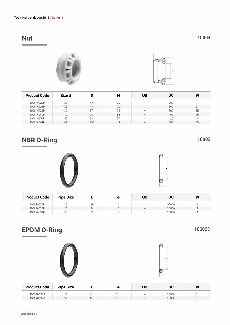
208 SERIES 1
Technical catalogue 2019 | Series 1
Nut 10004
D
H
d
Product Code Size d D H UB UC W
100040020P 20 40 22 — 700 7100040025P 25 45 22 — 500 8100040032P 32 57 24 — 300 15100040040P 40 68 33 — 400 29100040050P 50 83 37 — 125 44100040063P 63 100 43 — 100 60
NBR O-Ring 10002
e
E
Product Code Pipe Size E e UB UC W
100020020P 20 19 4 — 32000 1100020025P 25 24 5 — 16000 2100020032P 32 31 6 — 10000 4
EPDM O-Ring 10002D
e
E
Product Code Pipe Size E e UB UC W
10002D025P 25 24 5 — 16000 210002D032P 32 31 6 — 10000 4

209SERIES 1
MEC
HAN
ICAL
FIT
TIN
GS
ELEC
TRO
FUSI
ON
FIT
TIN
GS
SERI
ES 1
SILV
ER L
INE
NBR Shaped Seal 100029
e
E
Product Code Pipe Size E e UB UC W
100029040P 40 38 10 — 4000 8100029050P 50 48.6 10.5 — 2500 11100029063P 63 60.6 11.2 — 2000 15
EPDM Shaped Seal 10002D
e
E
Product Code Pipe Size E e UB UC W
10002D940P 40 38 10 — 4000 810002D950P 50 48.6 10.5 — 2500 1110002D963P 63 60.6 11.2 — 2000 15
Split Ring 10003
H
dD
Product Code Size d D H UB UC W
100030020P 20 27 9 — 6000 2100030025P 25 33 9 — 4500 3100030032P 32 42 11 — 2000 4100030040P 40 52 14 — 1600 14100030050P 50 64 17 — 500 14100030063P 63 81 21 — 500 27

210 SERIES 1
Technical catalogue 2019 | Series 1
Grip Ring 10008
H
h
d D
Product Code Size d D H h UB UC W
100080020P 20 27 3.8 1.8 — 7000 1100080025P 25 33 3.7 1.7 — 5500 1100080032P 32 42 3.7 1.7 — 3000 1100080040P 40 52 4.0 2.2 — 2500 2100080050P 50 64 4.3 2.5 — 1000 3100080063P 63 80 4.8 3.0 — 1000 6
PVC Pipe Adaptor Kit 1091Q
I
d E
Product Code Size d E I UB UC W
1091Q0025 25 47 50 1 500 261091Q0032 32 58 55 1 400 311091Q0040 40 70 72 1 300 561091Q0050 50 85 78 1 250 701091Q0063 63 103 95 1 100 134

211SERIES 1
MEC
HAN
ICAL
FIT
TIN
GS
ELEC
TRO
FUSI
ON
FIT
TIN
GS
SERI
ES 1
SILV
ER L
INE
Installation Instructions
1
2
3
Disassembly
1
2

212 SERIES 1
Technical catalogue 2019 | Series 1
Assembly Instructions PVC Pipe Kit
1
2 NEW

213SERIES 1
MEC
HAN
ICAL
FIT
TIN
GS
ELEC
TRO
FUSI
ON
FIT
TIN
GS
SERI
ES 1
SILV
ER L
INE


216 SILVER LINE
Technical catalogue 2019 | Silver Line
140100
Page 218 CouplingEnlace Recto
140200
Page 218 Male AdaptorEnlace Mixto Rosca Macho
140300
Page 219 Female AdaptorEnlace Mixto Rosca Hembra
141200
Page 219 End PlugTapón Final
140400
Page 220 90º TeeTe de 90º
141400
Page 220 90º Tee with Threaded Female OfftakeTe de 90º Compresión Rosca Hembra
148400
Page 221 90º Tee with Threaded Male OfftakeTe de 90º Compresión Rosca Macho
143400
Page 221 90º Reducing Tee with Irrift OutletTe de 90º Reductor
140500
Page 222 90º ElbowCodo de 90º
141500
Page 222 90º Elbow with Threaded Female OfftakeCodo de 90º Compresión Rosca Hembra
148500
Page 223 90º Elbow with Threaded Male OfftakeCodo de 90º Compresión Rosca Macho
146500
Page 223 Corner ElbowCodo de Esquina
149300
Page 224 Reducing SetJuego Reductor
1401 M0
Page 224 Coupler Union AdaptorEnlace Recto Con Racor
1498M0
Page 225 Union AdaptorAdaptador A Rosca Macho
078901
Page 225 Threaded Male AdaptorAdaptador Compresión Rosca Macho
Silver Line

217SILVER LINE
MEC
HAN
ICAL
FIT
TIN
GS
ELEC
TRO
FUSI
ON
FIT
TIN
GS
SERI
ES 1
SILV
ER L
INE
148940
Page 226 Nut Threaded AdaptorTuerca para Adaptador de Compresión
140040
Page 226 NutRacor
140030
Page 227 Split Ring - PolyacetalCasquillo de Apriete (acetal)
070020
Page 227 O-RingJunta Tórica/Seiil
140050
Page 228 InsertInserto de PP

218 SILVER LINE
Technical catalogue 2019 | Silver Line
Coupling 140100
Enlace Recto
H
dE
I I
Product Code Size d x d E H I UB UC W
140100016 16 x 16 39 105 50 10 400 48140100020 20 x 20 42 90 44 10 500 35140100025 25 x 25 50 98 48 10 300 56140100032 32 x 32 61 114 56 10 160 100140100040 40 x 40 73 127 62 5 100 150140100050 50 x 50 92 146 71 5 60 245140100063 63 x 63 106 167 82 2 40 400
Male Adaptor 140200
Enlace Mixto Rosca Macho
H
d ER
I2 I
Product Code Size d x R E H I I2 UB UC W
140200016003 16 x 3/8" 32 73 59 13 10 500 32140200016005 16 x 1/2" 39 79 59 16 10 500 32140200016007 16 x 3/4" 39 80 59 17 10 500 33140200020005 20 x 1/2" 42 71 50 17 10 600 23140200020007 20 x 3/4" 42 71 50 18 10 600 24140200025005 25 x 1/2" 50 75 54 17 10 480 34140200025007 25 x 3/4" 50 75 54 17 10 480 35140200025010 25 x 1" 50 77 50 18 10 480 37140200032007 32 x 3/4" 61 82 66 20 10 280 58140200032010 32 x 1" 61 84 60 18 10 280 58140200032013 32 x 1 1/4" 61 86 58 20 10 280 65140200040010 40 x 1" 73 97 73 22 5 150 90140200040013 40 x 1 1/4" 73 99 73 20 5 150 94140200040015 40 x 1 1/2" 73 98 73 22 5 150 95140200050015 50 x 1 1/2" 92 107 80 22 5 100 147140200050020 50 x 2" 92 110 90 26 5 100 152140200063020 63 x 2" 106 120 99 26 2 60 273

219SILVER LINE
MEC
HAN
ICAL
FIT
TIN
GS
ELEC
TRO
FUSI
ON
FIT
TIN
GS
SERI
ES 1
SILV
ER L
INE
Female Adaptor 140300
Enlace Mixto Rosca Hembra
H
d EG
I2 I
Product Code Size d x G E H I I2 UB UC W
140300016005 16 x 1/2" 39 77 55 19 10 500 37140300016007 16 x 3/4" 39 79 56 19 10 500 35140300020005 20 x 1/2" 42 71 51 18 10 600 26140300020007 20 x 3/4" 42 72 51 19 10 600 29140300025007 25 x 3/4" 50 75 54 19 10 400 38140300025010 25 x 1" 50 80 54 21 10 400 42140300032007 32 x 3/4" 61 82 61 19 10 280 63140300032010 32 x 1" 61 84 61 21 10 230 62140300040010 40 x 1" 73 97 73 21 5 150 97140300040013 40 x 1 1/4" 73 101 73 25 5 150 112140300040015 40 x 1 1/2" 73 101 73 25 5 150 122140300050015 50 x 1 1/2" 92 107 82 25 5 90 173140300050020 50 x 2" 92 112 82 30 5 90 192140300063020 63 x 2" 106 119 86 30 2 60 262
End Plug 141200
Tapón Final
H
d E
I
Product Code Size d E H I UB UC W
141200025 25 50 59 48 10 520 30141200032 32 61 67 54 10 330 53141200040 40 73 80 67 10 180 84141200050 50 92 93 71 5 100 54141200063 63 105 112 80 2 60 86

220 SILVER LINE
Technical catalogue 2019 | Silver Line
90º Tee 140400
Te de 90º
H
dE
AI
II
Product Code Size d x d x d E H I A UB UC W
140400016 16 x 16 x 16 39 126 50 63 10 200 79140400020 20 x 20 x 20 42 113 43 57 10 250 77140400025 25 x 25 x 25 50 124 47 60 10 170 85140400032 32 x 32 x 32 61 150 56 75 5 100 148140400040 40 x 40 x 40 73 173 62 86 5 60 244140400050 50 x 50 x 50 92 207 74 104 2 32 394140400063 63 x 63 x 63 106 239 82 119 2 20 643
90º Tee with Threaded Female Offtake 141400
Te de 90º Compresión Rosca Hembra
H
d E
A
G
I2
II
Product Code Size d x G x d E H I I2 A UB UC W
141400016005 16 x 1/2" x 16 39 124 51 19 30 10 240 66141400016007 16 x 3/4" x 16 39 122 50 19 30 10 240 59141400020005 20 x 1/2" x 20 42 113 44 18 43 10 320 48141400020007 20 x 3/4" x 20 42 113 44 19 45 10 320 50141400025005 25 x 1/2" x 25 50 123 48 18 45 10 200 71141400025007 25 x 3/4" x 25 50 123 48 19 48 10 200 71141400025010 25 x 1" x 25 50 123 48 21 50 10 200 75141400032005 32 x 1/2" x 32 61 150 56 18 49 5 120 120141400032007 32 x 3/4" x 32 61 150 56 19 52 5 120 118141400032010 32 x 1" x 32 61 150 56 21 55 5 120 123141400040010 40 x 1" x 40 73 173 62 21 63 5 70 188141400040013 40 x 1 1/4" x 40 73 173 62 25 67 5 70 207141400040015 40 x 1 1/2" x 40 73 173 62 25 68 5 60 204141400050015 50 x 1 1/2" x 50 92 200 72 25 73 2 40 323141400050020 50 x 2" x 50 92 200 72 30 79 2 40 348141400063020 63 x 2" x 63 106 239 82 30 86 2 20 522

221SILVER LINE
MEC
HAN
ICAL
FIT
TIN
GS
ELEC
TRO
FUSI
ON
FIT
TIN
GS
SERI
ES 1
SILV
ER L
INE
90º Tee with Threaded Male Offtake 148400
Te de 90º Compresión Rosca Macho
H
d E
A
R
I2
II
Product Code Size d x R x d E H I I2 A UB UC W
148400016005 16 x 1/2" x 16 42 113 44 17 44 10 300 33148400020005 20 x 1/2" x 20 42 113 44 17 44 10 300 44148400025005 25 x 1/2" x 25 50 124 48 17 45 10 220 63148400025007 25 x 3/4" x 25 50 124 48 18 47 10 220 67148400032007 32 x 3/4" x 32 61 150 56 18 49 5 120 112148400032010 32 x 1" x 32 61 150 56 20 53 5 120 114148400040010 40 x 1" x 40 73 173 62 20 65 5 70 182148400040013 40 x 1 1/4" x 40 73 173 62 22 68 5 70 189148400040015 40 x 1 1/2" x 40 73 173 62 22 69 5 70 192148400050015 50 x 1 1/2" x 50 92 207 72 22 73 2 40 308148400050020 50 x 2" x 50 92 207 72 26 77 2 40 316148400063020 63 x 2" x 63 106 239 82 26 84 2 24 486
90º Reducing Tee with Irrifit Outlet 143400
Te de 90º ReductorA
dE
E1
H
d1
I
Product Code Size d x d1 x d E H I E1 A UB UC W
143400020016 20 x 16 x 20 42 113 44 34 48 10 300 56143400025016 25 x 16 x 25 50 124 48 34 50 10 200 70143400032016 32 x 16 x 32 61 150 56 34 54 5 100 117
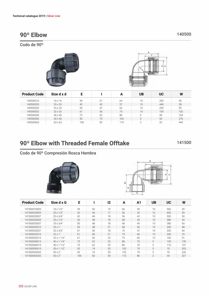
222 SILVER LINE
Technical catalogue 2019 | Silver Line
90º Elbow 140500
Codo de 90º
d E
AI
Product Code Size d x d E I A UB UC W
140500016 16 x 16 39 51 64 10 350 50140500020 20 x 20 42 43 57 10 440 38140500025 25 x 25 50 47 62 10 250 59140500032 32 x 32 61 56 75 10 150 102140500040 40 x 40 73 62 86 5 90 164140500050 50 x 50 92 74 104 5 50 276140500063 63 x 63 106 82 119 2 32 442
90º Elbow with Threaded Female Offtake 141500
Codo de 90º Compresión Rosca Hembra
A
d E
A1
G
I2
I
Product Code Size d x G E I I2 A A1 UB UC W
141500016005 16 x 1/2" 39 50 19 66 39 10 500 39141500020005 20 x 1/2" 42 44 17 56 42 10 600 29141500020007 20 x 3/4" 42 44 18 56 42 10 500 30141500025005 25 x 1/2" 50 48 18 68 45 10 380 44141500025007 25 x 3/4" 50 48 18 68 45 10 380 43141500025010 25 x 1" 50 48 21 68 50 10 340 48141500032007 32 x 3/4" 61 56 18 75 47 10 220 64141500032010 32 x 1" 61 56 21 75 60 10 200 70141500032013 32 x 1 1/4" 61 56 25 75 66 10 160 91141500040013 40 x 1 1/4" 73 62 25 86 70 5 120 130141500040015 40 x 1 1/2" 73 62 25 86 70 5 110 141141500050015 50 x 1 1/2" 92 74 25 102 79 5 70 203141500050020 50 x 2" 92 74 30 102 79 5 70 226141500063020 63 x 2" 106 82 30 115 86 2 44 327

223SILVER LINE
MEC
HAN
ICAL
FIT
TIN
GS
ELEC
TRO
FUSI
ON
FIT
TIN
GS
SERI
ES 1
SILV
ER L
INE
90º Elbow with Threaded Male Offtake 148500
Codo de 90º Compresión Rosca MachoA
d E
A1
R
I2
I
Product Code Size d x R E I I2 A A1 UB UC W
148500016005 16 x 1/2" 39 58 17 70 44 10 600 28148500016007 16 x 3/4" 39 58 18 70 45 10 600 28148500020005 20 x 1/2" 42 43 17 57 44 10 600 26148500020007 20 x 3/4" 42 43 18 57 45 10 600 29148500025005 25 x 1/2" 50 47 17 62 45 10 400 36148500025007 25 x 3/4" 50 47 18 62 47 10 400 39148500025010 25 x 1" 50 47 19 62 49 10 400 39148500032005 32 x 1/2" 61 56 17 75 49 10 240 65148500032007 32 x 3/4" 61 56 18 75 49 10 240 62148500032010 32 x 1" 61 56 20 75 53 10 240 66148500040010 40 x 1" 73 62 20 86 65 5 120 103148500040013 40 x 1 1/4" 73 62 22 86 68 5 120 114148500040015 40 x 1 1/2" 73 62 22 86 69 5 120 121148500050015 50 x 1 1/2" 92 74 22 104 73 5 70 176148500050020 50 x 2" 92 74 26 104 77 5 70 192148500063020 63 x 2" 106 82 26 119 84 2 48 248
Corner Elbow 146500
Codo de Esquina
A
dE
A1
G
I2
I
Product Code Size d x G E I I2 A A1 UB UC W
146500020005 20 x 1/2" 42 39 17 58 30 10 350 50146500025005 25 x 1/2" 50 44 17 62 30 10 250 70146500025007 25 x 3/4" 50 44 17 62 30 10 250 60
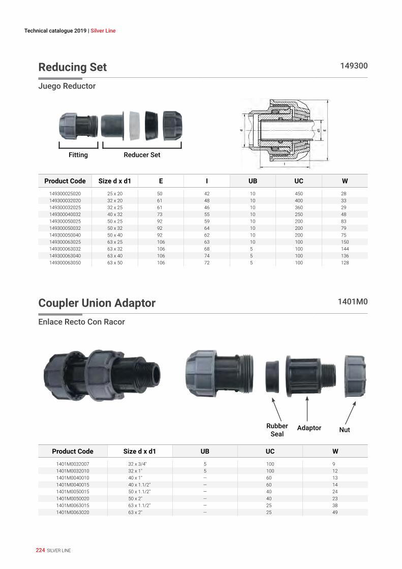
224 SILVER LINE
Technical catalogue 2019 | Silver Line
Reducing Set 149300
Juego Reductor
Reducer SetFitting
d1d E
I
Product Code Size d x d1 E I UB UC W
149300025020 25 x 20 50 42 10 450 28149300032020 32 x 20 61 48 10 400 33149300032025 32 x 25 61 46 10 360 29149300040032 40 x 32 73 55 10 250 48149300050025 50 x 25 92 59 10 200 83149300050032 50 x 32 92 64 10 200 79149300050040 50 x 40 92 62 10 200 75149300063025 63 x 25 106 63 10 100 150149300063032 63 x 32 106 68 5 100 144149300063040 63 x 40 106 74 5 100 136149300063050 63 x 50 106 72 5 100 128
Coupler Union Adaptor 1401M0
Enlace Recto Con Racor
NutRubber Seal
Adaptor
Product Code Size d x d1 UB UC W
1401M0032007 32 x 3/4" 5 100 91401M0032010 32 x 1" 5 100 121401M0040010 40 x 1" — 60 131401M0040015 40 x 1.1/2" — 60 141401M0050015 50 x 1.1/2" — 40 241401M0050020 50 x 2" — 40 231401M0063015 63 x 1.1/2" — 25 381401M0063020 63 x 2" — 25 49

225SILVER LINE
MEC
HAN
ICAL
FIT
TIN
GS
ELEC
TRO
FUSI
ON
FIT
TIN
GS
SERI
ES 1
SILV
ER L
INE
Union Adaptor 1498M0
Adaptador A Rosca Macho
Rd E
I2
I3I
Product Code Size d x R E I I2 I3 UB UC W
1498M0032007 32 x 3/4" 61 68 18 1 1 180 771498M0032010 32 x 1" 61 69 20 1 1 180 551498M0040010 40 x 1" 73 70 20 1 1 130 1421498M0040015 40 x 1.1/2" 73 71 22 1 1 130 891498M0050015 50 x 1.1/2" 92 73 24 1 1 80 1261498M0050020 50 x 2" 92 79 27 1 1 80 1331498M0063015 63 x 1.1/2" 106 75 22 1 1 60 —1498M0063020 63 x 2" 106 77 26 1 1 60 306
Threaded Male Adaptor 078901
Adaptador Compresión Rosca Macho
I1 I2L
D G
Product Code Size d x G L I1 I2 UB UC W
078901025005P 25 x 1/2" — — — 10 500 16.9078901025007P 25 x 3/4" — — — 10 500 19.4078901032005P 32 x 1/2" — — — 10 400 34.1078901032007P 32 x 3/4" — — — 10 400 35078901032010P 32 x 1" — — — 10 400 36.8078901040010P 40 x 1" — — — 10 220 53.7078901040013P 40 x 1.1/4" — — — — 220 56.8078901040015P 40 x 1.1/2" — — — 10 220 61078901050010P 50 x 1" — — — 5 140 80.6078901050013P 50 x 1.1/4" — — — — 140 83.9078901050015P 50 x 1.1/2" — — — 5 140 83.5078901050020P 50 x 2" — — — 5 140 91.1078901063010P 63 x 1" — — — — 80 137.6078901063013P 63 x 1.1/4" — — — — — 139.5078901063015P 63 x 1.1/2" — — — 5 80 139.7078901063020P 63 x 2" — — — 5 80 145.5078901063025P 63 x 2.1/2" — — — 5 80 158.2

226 SILVER LINE
Technical catalogue 2019 | Silver Line
Nut for Threaded Adaptor 148940
Tuerca para Adaptador de Compresión
Product Code Size d UB UC W
148940032P 32 10 400 15148940040P 40 10 200 23148940050P 50 10 140 37148940063P 63 — — 61
Nut 140040
Racor
Product Code Size d UB UC W
140040016P 16 — — 11140040020P 20 10 1600 8.1140040025P 25 10 1000 12140040032P 32 10 500 20.6140040040P 40 — 330 34140040050P 50 — 180 68140040063P 63 — 100 110

227SILVER LINE
MEC
HAN
ICAL
FIT
TIN
GS
ELEC
TRO
FUSI
ON
FIT
TIN
GS
SERI
ES 1
SILV
ER L
INE
Split Ring - Polyacetal 140030
Casquillo de Apriete (acetal)
Product Code Size d UB UC W
070030016P 16 100 12000 1140030020P 20 100 12000 2140030025P 25 100 7000 3140030032P 32 — 4200 4140030040P 40 — 2000 8140030050P 50 — 1200 12140030063P 63 — 600 24
O-Ring 070020
Junta Tórica/Seiil
Product Code Size d E1 e UB UC W
070020016 16 15 3 100 30000 1070020020 20 19 3 100 32000 1070020025 25 24 4 100 12000 1070020032 32 31 5 100 10000 2070020040 40 39 6 50 4000 5070020050 50 49 7 50 2500 8070020063 63 62 7 50 2000 10
228 SILVER LINE
Technical catalogue 2019 | Silver Line
Insert 140050
Inserto de PP
Product Code Size d UB UC W
070050016P 16 100 8700 1140050020P 20 100 10000 1.3140050025P 25 — 5500 2.4140050032P 32 50 3000 4.4140050040P 40 — 2000 5.6140050050P 50 — 1000 8.9140050063P 63 — 500 15.4

229SILVER LINE
MEC
HAN
ICAL
FIT
TIN
GS
ELEC
TRO
FUSI
ON
FIT
TIN
GS
SERI
ES 1
SILV
ER L
INE
Technical Specifications

230 SILVER LINE
Technical catalogue 2019 | Silver Line
Technical SpecificationsPlasson Silver Line - These fittings have been specially designed for joining polyethylene pipes used with a working pressure up to 10 bar. They are designed according to ISO standards and are available in sizes 16 - 63mm.
Features• Perfectly watertight• Extremely simple to use• Easy and fast to reuse• Designed with a captive O-ring• Frost proof• Suitable for outdoor use in direct sunlight• Highly impact resistant
MaterialsBody: Polypropylene, high-grade copolymerNut: Polypropylene, high-grade copolymerSplit Ring: Polyacetal (POM)Seal: Nitrile rubber (EPDM)
Operating TemperaturesThe fittings are not to be used with hot water, although they withstand the same temperature as the polyethylene pipe itself. The fittings and valves will withstand sub-zero temperatures.
ThreadsAll threads conform to ISO-7/1, BS 21 - 1973, DIN 2999, NEN 3258, AS 1722 Part 1 - 1975.
Technical Specifications
Installation Instructions For Fittings16mm - 63mm• Cut the pipe square, chamfer the end of the pipe• Undo the nut to the last thread. Leave the nut on the fitting
while inserting the pipe.• Twist the pipe into the fitting* through the split ring and
rubber seal to the pipe stop Tighten the nut firmly. Use a Plasson wrench (or similar tool) for final tightening of sizes 40 and above.
• The nut should be closed tightly, however there is no need for the nut to actually meet the body shoulder.
* Lubrication and chamfering of the pipe end will ease insertion of the pipe (use silicone lubricant).
NoteBefore installation ensure that the end of the pipe to be inserted into the fitting is free of scratches and other imperfections and that both the pipe and the fitting itself are clean of sand, mud, stones etc.
Do not over tighten nut when closing. Never use wrenches or spanners with handle lengths longer than 46 cm - excessive torque during tightening can spread nut cone and result in pull outs.
If fittings are reused, ensure split ring is sharp and bites into pipe to avoid pull outs. Alternatively replace split ring.
We strongly recommend the use of PTFE tape in threaded connections.
Legend
UB Units par bag
UC Units per carton
W Weight in grams

231SILVER LINE
MEC
HAN
ICAL
FIT
TIN
GS
ELEC
TRO
FUSI
ON
FIT
TIN
GS
SERI
ES 1
SILV
ER L
INE
Especificaciones TécnicasLos accesorios de la Línea Silver de Plasson han sido diseñados para la unión de tuberías de polietileno de alta densidad usados con una presión de trabajo de hasta 10 bar. Están diseñados de acuerdo a las normas ISO y están disponibles en diámetros de 16 - 63mm.
Características• Estanqueidad completa• Fácil instalación• Rápida reutilización• Diseñada con una junta tórica cautiva• Resistencia a bajas temperaturas• Frost Proof• Resistentes para instalación a la intemperie• Alta resistencia a golpes o impactos
MaterialesCuerpo: Polipropileno, block copolímero de alta calidadRacor: Polipropileno, block copolímero de alta calidadCasquillo de apriete: Polyacetal (POM)Junta tórica: Nitrilo (EPDM)
Temperaturas de TrabajoLos accesorios no son recomendados para usar con agua caliente, aunque soportan las mismas temperaturas que las propias tuberías de polietileno.Sin embargo pueden resistir temperaturas inferiores a los cero grados centigrados.
RoscasTodas las roscas responden a las normas ISO-7/1, BS 21,DIN 2999, NEN 3258, AS 1722 Part 1 - 1975.
Especificaciones Técnicas
Installation Instructions Para accesorios de16mm - 63mm• Corte el tubo al tamaño requerido y realice el biselado al
final del tubo• Retire el racor hasta su última rosca dejandolo en el
accesorio durante el próximo paso.• Introduzca el tubo con un movimiento circular dentro del
accesorio pasando el casquillo de apriete y el sello hasta llegar al tope interno del accesorio
• Gire firmamente el racor en direccion del cuerpo del accesorio, utilizando la llave Plasson (o similar) en los tamaños 40mm y mayores.
• Cierre el racor firmemente, aunque no es necesario cerrarlo hasta el tope.
* A fin de facilitar la introduccion es conveniente lubricar y biselar el tubo (con un lubricante que conforma las normas de aprovación de calidad del agua).
NotaAntes de la instalación asegure que:El extremo del tubo introducido no tenga imperfecciones o rayaduras Tanto el tubo como el accesorio no tenga sobre los mismos arena, barro o piedras,etc. No cierre el racor con extremada fuerza, nunca use llaves con manijas mas largas de 46 cm.
Un excesivo momento de torsion durante el cierre puede dañar el cono del racor y como resultado del mismo no permitir su propio funcionamiento Si los accesorios son usados nuevamente despues de su desarmado, constate que los dientes del casquillo de apriete permanecen afilados y se hincan en el tubo impidiendo el escape del tubo. Si no es asi, cambie el casquillo de apriete.
Recomendamos utilizar cinta de PTFE para sellar todas las conecciones roscadas.
Legend
UB Unidades por bolsa
UC Unidades por carton
W Peso en gramos

232 SILVER LINE
Technical catalogue 2019 | Silver Line

Catalogue 2019
w w w. p l a s s o n . c o m
GLOBAL PRESENCE - LOCAL COMMITMENT
08020210B_19
14073 12.18