carburator zenith 28rxz - cfiamerica.comcfiamerica.com/images/pdf/carburettor zenith 28rxz .pdf ·...
TRANSCRIPT
1
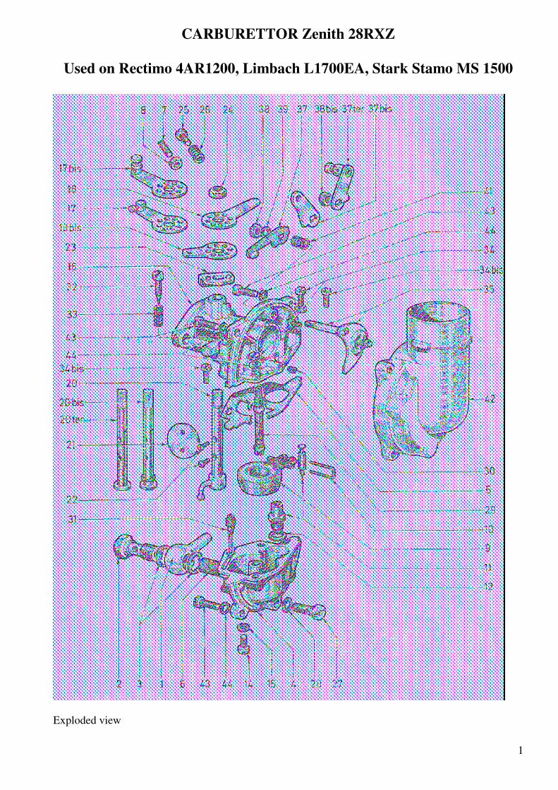
CARBURETTOR Zenith 28RXZ
Used on Rectimo 4AR1200, Limbach L1700EA, Stark Stamo MS 1500
Exploded view

2

3
The Zenith carburettor is designed for use with industrial and agricultural engines.
The carburettor’s main jet is in the centre of the base of a circular float bowl. The float and float bowl
are annular, so both the carburettor and engine will continue to operate correctly at high angles of pitch
and roll without the fuel level or operation being adversely affected.
The cast metal air inlet elbow (plenum) is completely sealed and fitted with an air filter to prevent the
entry of dust into the main venturi, the jets or the float bowl vent.
DESCRIPTION
The carburettor is composed of a main body (1), a float bowl (23) and an air inlet elbow (plenum) (10).
The main body incorporates the throttle butterfly, the choke and the atomiser (emulsion tube).
The float bowl incorporates the float and needle (float) valve mechanism.
The inlet elbow (plenum) has no moving parts.
METHOD OF OPERATION
Fuel flows through the fuel pipe banjo fitting (19), through the filter (18) and through the needle valve
jet (20) into the float bowl.
The float (22) is connected to the needle valve pin, and this maintains a constant level of fuel in the
float bowl.
NORMAL OPERATION
Fuel passes through the main jet (12) and flows up inside the emulsion tube (14). Air is introduced
through the air jet (11), into the emulsion tube through its side holes (13) into the atomizer. The
resulting air/fuel emulsion is sucked into the main venturi. The layout and size of the holes (13)
automatically ensure the proper mixture for correct functioning of the engine.

4
IDLING (slow running)
During slow running, fuel is sucked through the idle jet (16). This fuel is drawn into the idle mixture
gallery (17) where it combines with air drawn through the slow-running mixture adjusting screw (6), to
form an emulsion which is sucked into the venturi beside the throttle butterfly the at the idle (3) port.
A further opening (4) ensures the right amount and quality of fuel/air mixture during the first few
degrees of opening of the throttle butterfly during acceleration or under load.
COLD STARTING
For cold starting the fuel/air mixture must be richer than during normal running with a warm engine.
This enrichment is achieved using a choke plate (8)incorporating a relief valve (9), which opens
automatically under the influence of increased intake suction in the venturi.
After starting, the choke (8) should be gradually opened by operating the lever (7). When the engine has
reached its optimum temperature, the choke should be in its fully open position.
ADJUSTMENT AND MAINTENANCE
Each carburettor is supplied with the proper settings for the engine for which it is intended, so no
adjustment should be necessary.
The correct idling mixture can be adjusted by setting the idling air screw. Any adjustment should be
made when the engine is warm.
Loosening this screw (6) causes a weaker mixture, while tightening causes enrichment.
The throttle stop screw (5) on the throttle lever bar controls the engine’s idle speed.
In principle, the carburettor should not need any maintenance, only a regular cleaning of the float bowl
to remove any impurities that may occur over time.
AIR FILTER
Engine life is influenced by good air filtration. The ZENITH Company has therefore developed
specifically for their 28RXZ carburettor a paper filter element FA50 P20 with a large filtration surface.
MISCELLANEOUS DATA (figures are metric)
Choke ............................................................................................................................... .22
Main jet (27) on Rectimo 4AR 1200, Sauer-Rectimo 1400, Stark Stamo 1500 .................... 1.25
Main air bleed (30) ....................................................................................................... 1.00
Slow running jet (31) ....................................................................................................... .60
Level ............................ 9 mm below top face of float chamber under a head of 30 cm fuel
Needle valve (float) on fuel pump feed engines (Limbach and Stamo) ………………………… 1.5
Needle valve (float) on engines without fuel pump (Rectimo) …………………………………. 2.5