canuck - pcmuseum.tripod.com
TRANSCRIPT
OWNER’S HANDBOOK
AIRCRAFT 025 ONSPARE PARTS
SPECIAL MAINTENANCEINSTRUCTIONS
6-23-46
CANUCK
FLEET AIRCRAFT ... FORT ERIE, CANADA
SPECIAL MAINTENANCE INSTRUCTIONS
Fuel System
The fuel injector pump circulates gasoline continuously from the tank through the injector andback to the tank, providing an ample flow of gasoline to the engine, but aloso preventing dirt in thesystem from settling out, and increasing the possibilities of leakage.Strainers should be cleaned regularly. If leaks cannot be stopped by tightening the sleeve nuts to 112inch pounds, the parts should be replaced. Do not use sealing compounds.
The gasoline return line to the tank enters the bottom of the tank, through a tube inside the tank,to empty near the top of the tank. A flow of gasoline from the return line when disconnected indicates acrack in the tube inside the tank, which should be repaired on overhaul.
Landing Gear
The wheels are magnesium alloy, which corrodes easily if the finish is damaged, Worn spots,cracks, scratches and chips must be refinished, using zinc chromate primer, or aluminium pigment pastein lacquer thinner (10 pounds to 3 gallons.)
Bleeding brakes is accomplished by filling the pedal cylinders, removing the bleed screw at thewheel. As the level in the cylinder goes down, replace the screw and refill. Repeat until no air bubblesappear. It is difficult to add fluid continuously during bleeding without introducing air into the cylinders.
The brakes have no adjustment, and require no adjustment.
To replace brake linings, remove the wheel. Slide the brake ring clear and the limings can beslipped cut and replaced.DO NOT DISSASSEMBLE THE CYLINDER. If the cylinder must be taken apart, it can be done witha small arbour press, but the rubber sealing rings will be damaged and will require replacement on re-assembly.
To replace Aero Rings, jack wheel clear of ground. Remove center floor panel - this will savetime, as it is difficult to replace the rings from the bottom, and it will make it easier to install the ringswithout damaging them. Slip ring on the front fitting first, then use a large screwdriver to pry over therear fitting. Run succeeding rings in the centre of those already on.
ENGINE MAINTENANCE
For engine maintenance, refer to the Continental Operators Handbook, included with thishandbook.
FUEL INJECTION
The fuel injector is an Excello Model A41. All rotating parts of the pump are lubricated by oiltaken from the engine pressure lubricating system.
Clean sediment bowl regularly.
Except for the engine idle speed adjusting screw at the bottom of the air throttle valve, no adjust-ments to the injector or linkage should be attempted except by licensed mechanics or experiencedoperators. Adjustment of the linkage will most likely be necessary after the engine has been oeperated40 or 50 hours, or if the aircraft is operated under much different atmospheric conditions, or if thepropellor is changed, or if a new pump is installed. In case of unsatisfactory engine perormance it isadvisable to check spark plugs, fuel pressure, magnetos and injection nozzles before adjusting theinjector linkage.
The linkage between the air valve and the injector valve is adjusted until the engine will respondimmediately and smoothly when the throttle is opened quickly. Lock the nuts on the linkage. Set the idleair adjustment stop screw for approximately 650 R.P.M. Adjust idle adjustment screw at the bottom ofthe air throttle valve to obtain smoothest engine operation - not highest speed. Reset idle air adjustmentstop screw for approximately 650 R.P.M. Set full throttle stop screw at top R.P.M.
Increasing length of link is enriching mixture.
NOZZLES
Clean outside of nozzle in gasoline and dry with air. Remove snap ring and valve. Clean, oil andreplace nozzle in valve, using a wooden stick to move valve back and forth in nozzle. Remove again,clean, and replace. If valve is still sticky in operation, the nozzle must be replaced.
If air can be sucked thru the nozzle from either end it should be replaced.
TROUBLE SHOOTING
Leaking nozzles will cause poor acceleration and missing after a long glide.
Sticking nozzles will cause missing and rough running at engine speeds up to 1500 R.P.M.,clearing up higher R.P.M. Sticking nozzles also cause hard starting.
Leakage at the injection line connections will cause rough running and missing.
Incorrect linkage adjustment results in too lean or too rich mixture and poor acceleration, roughrunning and overheating.
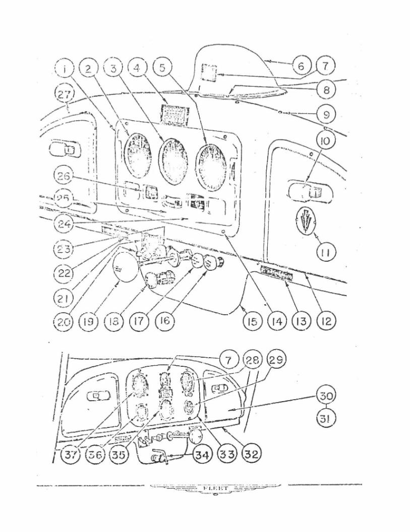
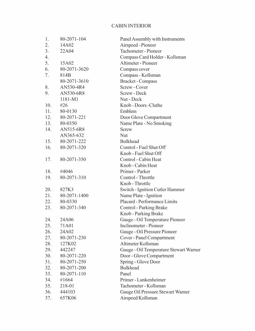
CABIN INTERIOR
1. 80-2071-104 Panel Assembly with Instruments2. 14A02 Airspeed - Pioneer3. 22A04 Tachometer - Pioneer4. Compass Card Holder - Kollsman5. 15A02 Altimeter - Pioneer6. 80-2071-3620 Compass cover7. 814B Compass - Kollsman
80-2071-3610 Bracket - Compass8. AN530-4R4 Screw - Cover9. AN530-6R8 Screw - Deck
1181-M1 Nut - Deck10. #26 Knob - Doors -Cluthe11. 80-0130 Emblem12. 80-2071-221 Door Glove Compartment13. 80-0350 Name Plate - No Smoking14. AN515-6R8 Screw
AN365-632 Nut15. 80-2071-222 Bulkhead16. 80-2071-320 Control - Fuel Shut Off
Knob - Fuel Shut Off17. 80-2071-350 Control - Cabin Heat
Knob - Cabin Heat18. #4046 Primer - Parker19. 80-2071-310 Control - Throttle
Knob - Throttle20. 827K3 Switch - Ignition Cutler Hammer21. 80-2071-1400 Name Plate - Ignition22. 80-0330 Placard - Performance Limits23. 80-2071-340 Control - Parking Brake
Knob - Parking Brake24. 24A06 Gauge - Oil Temperature Pioneer25. 71A01 Inclinometer - Pioneer26. 24A02 Gauge - Oil Pressure Pioneer27. 80-2071-230 Cover - Panel Compartment28. 127K02 Altimeter Kollsman29. 442247 Gauge - Oil Temperature Stewart Warner30. 80-2071-220 Door - Glove Compartment31. 80-2071-250 Spring - Glove Door32. 80-2071-200 Bulkhead33. 80-2071-110 Panel34. #1664 Primer - Lunkenheimer35. 218-01 Tachometer - Kollsman36. 444103 Gauge Oil Pressure Stewart Warner37. 657K06 Airspeed Kollsman
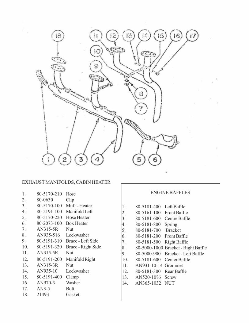
EXHAUST MANIFOLDS, CABIN HEATER
1. 80-5170-210 Hose2. 80-0630 Clip3. 80-5170-100 Muff - Heater4. 80-5191-100 Manifold Left5. 80-5170-220 Hose Heater6. 80-2073-100 Box Heater7. AN315-5R Nut8. AN935-516 Lockwasher9. 80-5191-310 Brace - Left Side10. 80-5191-320 Brace - Right Side11. AN315-5R Nut12. 80-5191-200 Manifold Right13. AN315-3R Nut14. AN935-10 Lockwasher15. 80-5191-400 Clamp16. AN970-3 Washer17. AN3-5 Bolt18. 21493 Gasket
ENGINE BAFFLES
1. 80-5181-400 Left Baffle 2. 80-5161-100 Front Baffle 3. 80-5181-600 Centre Baffle 4. 80-5181-800 Spring 5. 80-5181-700 Bracket 6. 80-5181-200 Front Baffle 7. 80-5181-500 Right Baffle 8. 80-5000-1000 Bracket - Right Baffle 9. 80-5000-900 Bracket - Left Baffle 10. 80-5181-600 Center Baffle 11. AN931-10-14 Grommet 12. 80-5181-300 Rear Baffle 13. AN520-10?6 Screw 14. AN365-1032 NUT
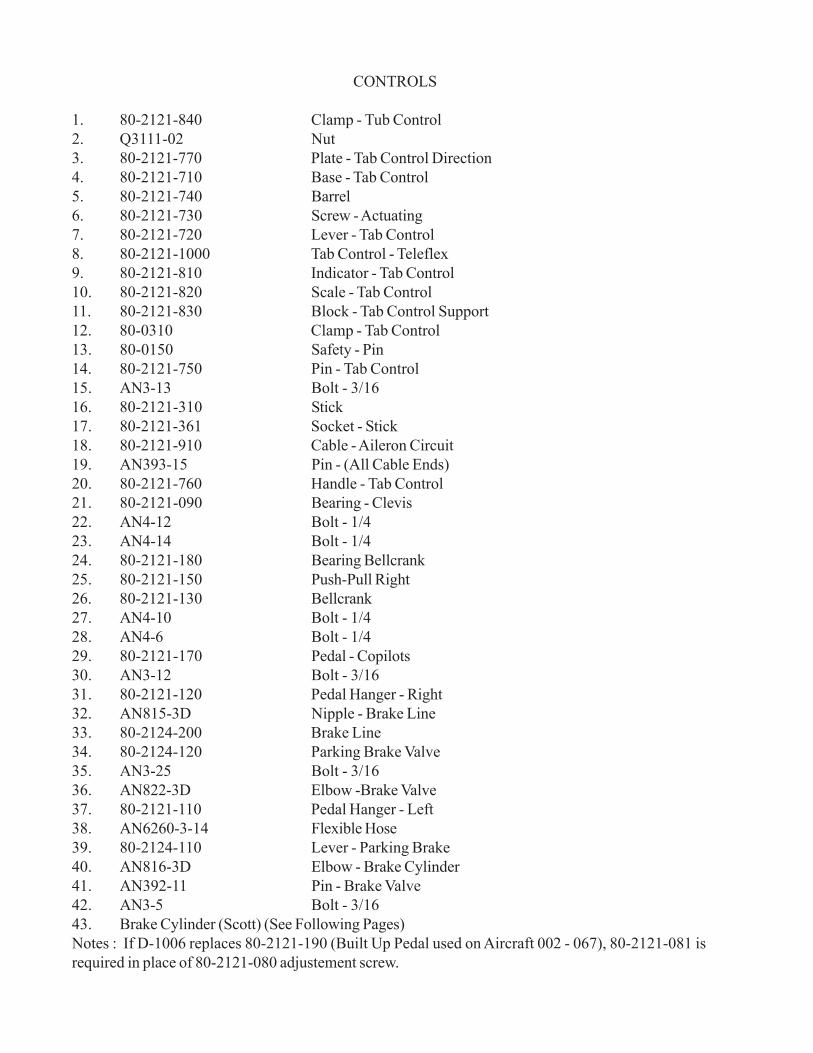
CONTROLS
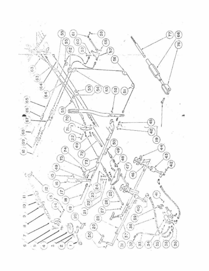
1. 80-2121-840 Clamp - Tub Control2. Q3111-02 Nut3. 80-2121-770 Plate - Tab Control Direction4. 80-2121-710 Base - Tab Control5. 80-2121-740 Barrel6. 80-2121-730 Screw - Actuating7. 80-2121-720 Lever - Tab Control8. 80-2121-1000 Tab Control - Teleflex9. 80-2121-810 Indicator - Tab Control10. 80-2121-820 Scale - Tab Control11. 80-2121-830 Block - Tab Control Support12. 80-0310 Clamp - Tab Control13. 80-0150 Safety - Pin14. 80-2121-750 Pin - Tab Control15. AN3-13 Bolt - 3/1616. 80-2121-310 Stick17. 80-2121-361 Socket - Stick18. 80-2121-910 Cable - Aileron Circuit19. AN393-15 Pin - (All Cable Ends)20. 80-2121-760 Handle - Tab Control21. 80-2121-090 Bearing - Clevis22. AN4-12 Bolt - 1/423. AN4-14 Bolt - 1/424. 80-2121-180 Bearing Bellcrank25. 80-2121-150 Push-Pull Right26. 80-2121-130 Bellcrank27. AN4-10 Bolt - 1/428. AN4-6 Bolt - 1/429. 80-2121-170 Pedal - Copilots30. AN3-12 Bolt - 3/1631. 80-2121-120 Pedal Hanger - Right32. AN815-3D Nipple - Brake Line33. 80-2124-200 Brake Line34. 80-2124-120 Parking Brake Valve35. AN3-25 Bolt - 3/1636. AN822-3D Elbow -Brake Valve37. 80-2121-110 Pedal Hanger - Left38. AN6260-3-14 Flexible Hose39. 80-2124-110 Lever - Parking Brake40. AN816-3D Elbow - Brake Cylinder41. AN392-11 Pin - Brake Valve42. AN3-5 Bolt - 3/1643. Brake Cylinder (Scott) (See Following Pages)Notes : If D-1006 replaces 80-2121-190 (Built Up Pedal used on Aircraft 002 - 067), 80-2121-081 isrequired in place of 80-2121-080 adjustement screw.
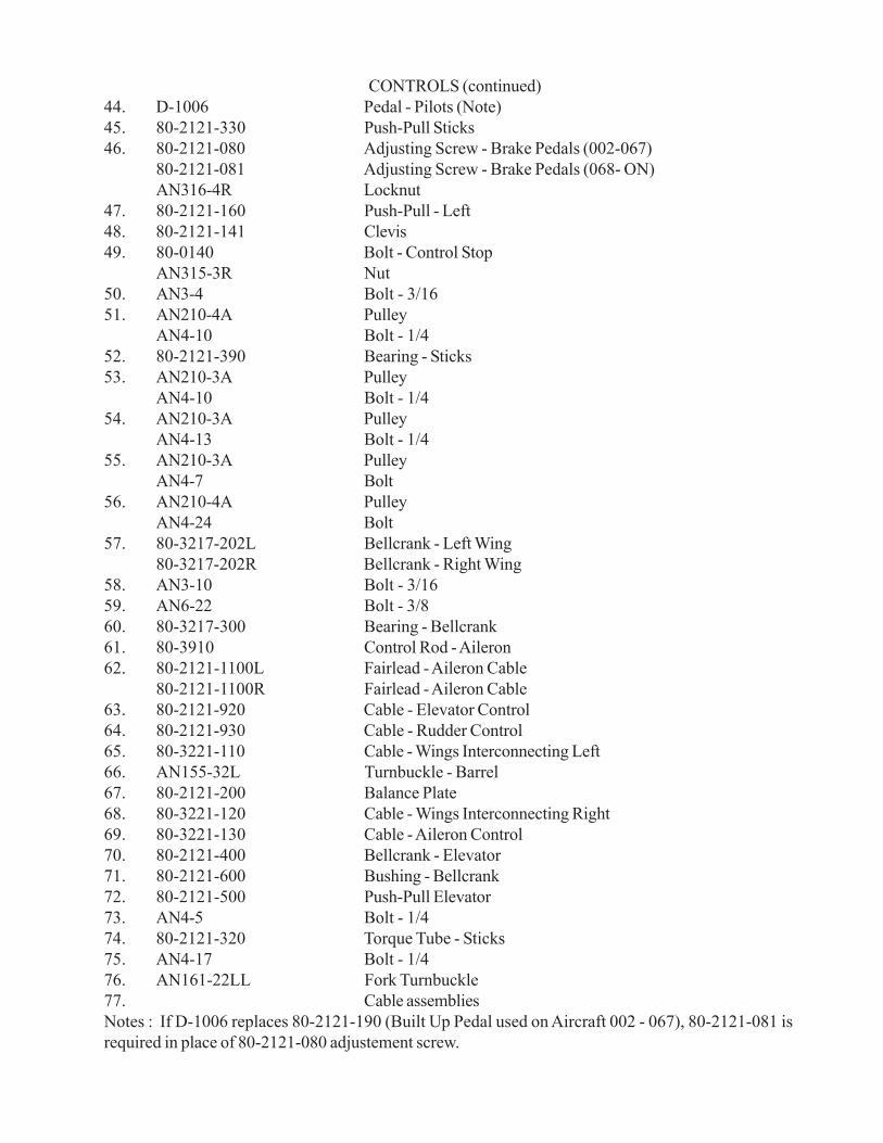
CONTROLS (continued)44. D-1006 Pedal - Pilots (Note)45. 80-2121-330 Push-Pull Sticks46. 80-2121-080 Adjusting Screw - Brake Pedals (002-067)
80-2121-081 Adjusting Screw - Brake Pedals (068- ON)AN316-4R Locknut
47. 80-2121-160 Push-Pull - Left48. 80-2121-141 Clevis49. 80-0140 Bolt - Control Stop
AN315-3R Nut50. AN3-4 Bolt - 3/1651. AN210-4A Pulley
AN4-10 Bolt - 1/452. 80-2121-390 Bearing - Sticks53. AN210-3A Pulley
AN4-10 Bolt - 1/454. AN210-3A Pulley
AN4-13 Bolt - 1/455. AN210-3A Pulley
AN4-7 Bolt56. AN210-4A Pulley
AN4-24 Bolt57. 80-3217-202L Bellcrank - Left Wing
80-3217-202R Bellcrank - Right Wing58. AN3-10 Bolt - 3/1659. AN6-22 Bolt - 3/860. 80-3217-300 Bearing - Bellcrank61. 80-3910 Control Rod - Aileron62. 80-2121-1100L Fairlead - Aileron Cable
80-2121-1100R Fairlead - Aileron Cable63. 80-2121-920 Cable - Elevator Control64. 80-2121-930 Cable - Rudder Control65. 80-3221-110 Cable - Wings Interconnecting Left66. AN155-32L Turnbuckle - Barrel67. 80-2121-200 Balance Plate68. 80-3221-120 Cable - Wings Interconnecting Right69. 80-3221-130 Cable - Aileron Control70. 80-2121-400 Bellcrank - Elevator71. 80-2121-600 Bushing - Bellcrank72. 80-2121-500 Push-Pull Elevator73. AN4-5 Bolt - 1/474. 80-2121-320 Torque Tube - Sticks75. AN4-17 Bolt - 1/476. AN161-22LL Fork Turnbuckle77. Cable assembliesNotes : If D-1006 replaces 80-2121-190 (Built Up Pedal used on Aircraft 002 - 067), 80-2121-081 isrequired in place of 80-2121-080 adjustement screw.
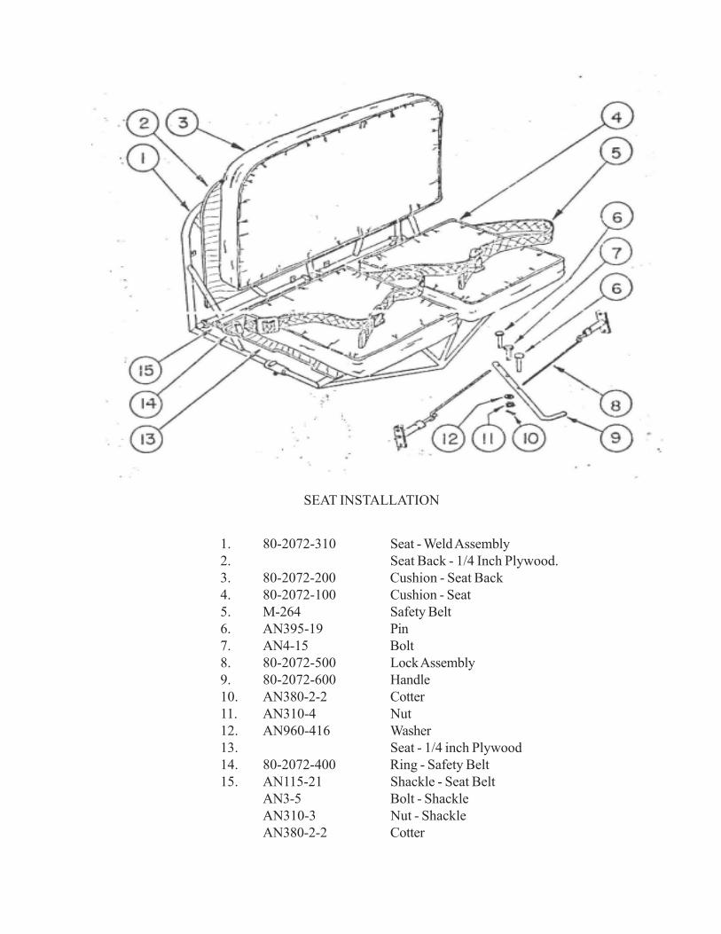
1. 80-2072-310 Seat - Weld Assembly2. Seat Back - 1/4 Inch Plywood.3. 80-2072-200 Cushion - Seat Back4. 80-2072-100 Cushion - Seat5. M-264 Safety Belt6. AN395-19 Pin7. AN4-15 Bolt8. 80-2072-500 Lock Assembly9. 80-2072-600 Handle10. AN380-2-2 Cotter11. AN310-4 Nut12. AN960-416 Washer13. Seat - 1/4 inch Plywood14. 80-2072-400 Ring - Safety Belt15. AN115-21 Shackle - Seat Belt
AN3-5 Bolt - ShackleAN310-3 Nut - ShackleAN380-2-2 Cotter
SEAT INSTALLATION
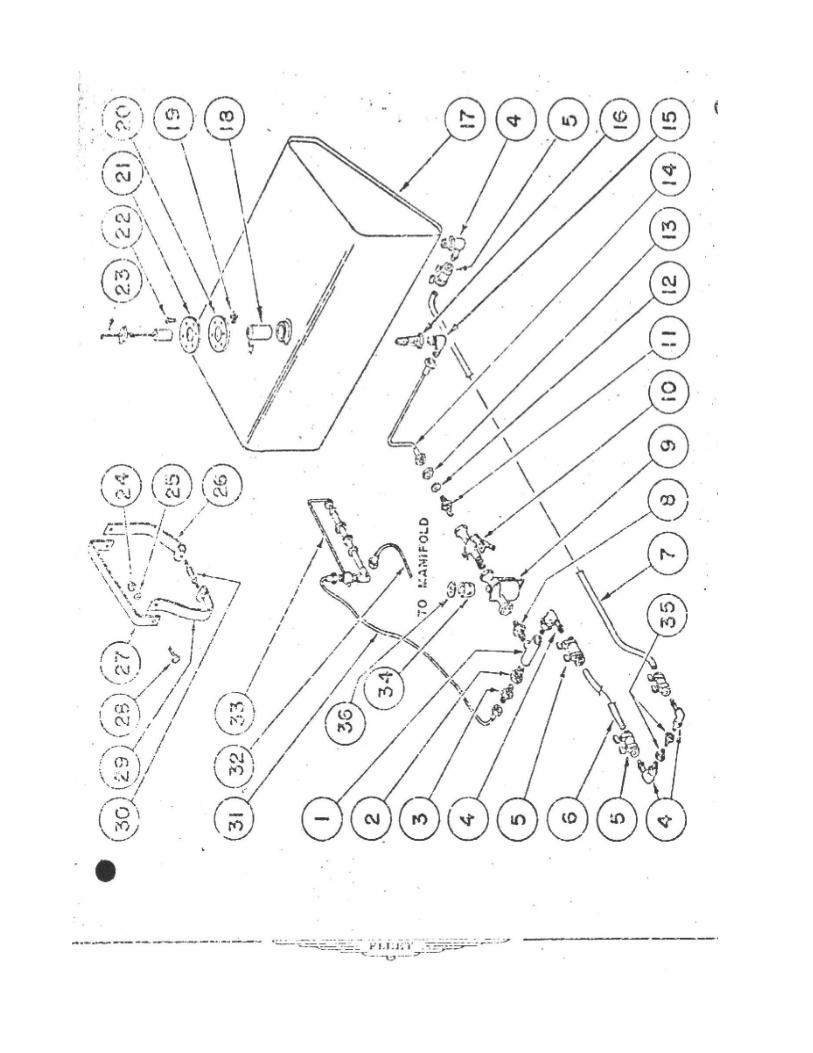
FUEL SYSTEM
1. AN917-2D Tee2. AN912-1D Reducer3. AN780-2 Nipple4. AN842-6D Adaptor5. AN884-6-24 Hose
F B C - 4 Clamp6. 80-5000-1 Tube7. 80-5000-2 Tube8. AN911-2D Nipple9. 446S Carter Filter
23A16 Carter GasketCarter Bowl
10. 80-2131-1101 Shut Off Valve11. 80-2131-600 Nipple12. AN960-01016 Washer13. AN924-6D Locknut14. 80-21310500 Tube15. AN822-6D Elbow16. 80-2131-800 Strainer17. 80-2131-100 Tank (With Neck, Cap, Gauge)18. 80-2131-110 Filler Neck19. 6052-6Z Speednut20. 80-2131-700 Gasket21. 80-2131-900 Ring22. AN530-6R6 Screw23. 80-2131-140 Cap
80-2131-130 Gauge24. AN365-1032 Stopnut25. AN960-10 Washer26. 80-2131-210R Strap27. 80-2131-220 Strap28. AN3-3A Bolt29. 80-2131-210L Strap30. 80-2131-230 Turnbuckle31. 80-2131-1510 Tube32. 80-2131-1520 Tube33. 4046 Primer - Parker34. 23-27 Ceramic Filter35. 3204x4 Nipple - Injector -Weatherhead36. 23A16 Gasket - Filter
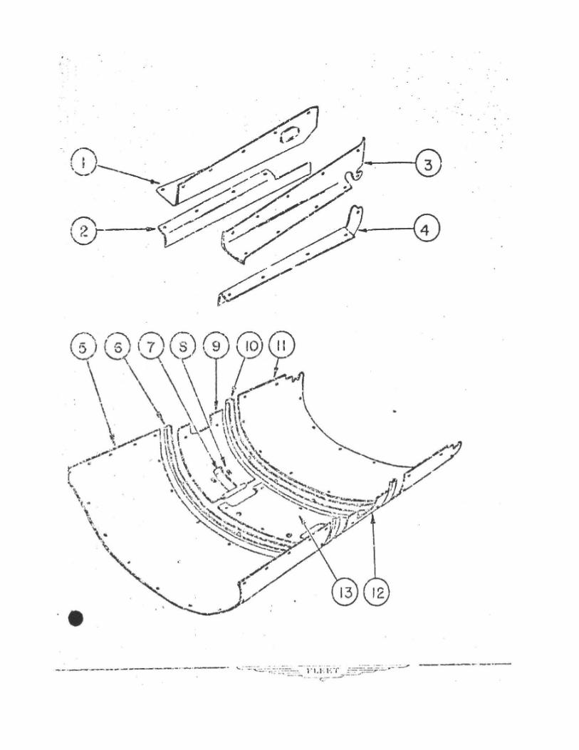
FAIRINGS
1. 80-2021-301 Fairing - Tail Upper - R.H.2. 80-2021-401 Fairing - Tail Lower - R.H.3. 80-2021-601 Fairing - Tail Upper - L.H.4. 80-2021-501 Fairing - Tail Lower - L.H.5. 80-2015-000 Cowl - Bottom Front6. 80-2012-620 Bulkhead - Fuselage Fairing7. 80-2023-000 Cover - Landing Gear Center8. #8 x 3/8 Z-S P.K. Screw9. 80-2022-000R Cowl - Landing Gear Side Right10. 80-2012-630 Bulkhead - Fuselage Fairing11. 80-2016-001 Cowl - Bottom Rear12. 80-2022-000L Cowl - Landing Gear Side Left13. 80-2021-000 Cowl - Landing Gear Center
Bottom cowling panels are supplied undrilled and oversize to allow for trimming on assembly.
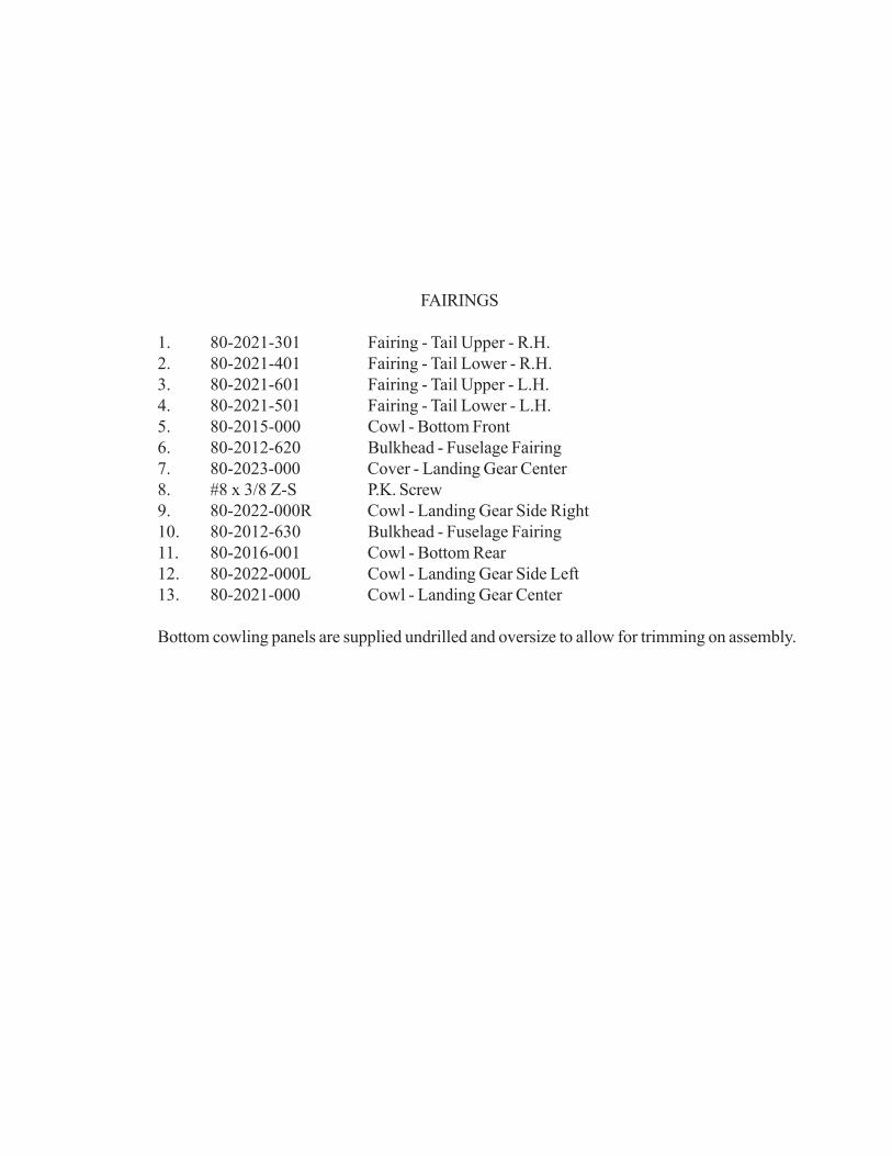
WINGSWhen wings or main struts are replaced, the wing incidence at the strut is checked to the same
angle as the root rib, which is fixed by the fuselage.In removing the wing or struts, do not disconnect the pitot head from the pitot lines.
The coupling is a compression type and semi permanent. Pitot lines are drained by disconnecting theunion under the instrument panel and blowing thru. Do not blow thru the instruments.
Aileron Travel up 23deg. Down 14deg. (Measured from drooped position) Droop is 1/2 inch attrailing edge.1. 80-9202L Wing - Wired (Less Lights, Less Aileron, With Cables) Left.
80-9202R Wing - Wired (Less Lights, Less Aileron, With Cables) Right.AN6-20 Bolt - Wing Foot Front.AN960-616 WasherAN310-6 NutAN380-3-3 CotterAN5-16 Bolt -Wing Foot rearAN960-516 WasherAN310-5 NutAN380-2-2 Cotter
2. 80-3300L Aileron Left80-3300R Aileron RightAN4-12 Bolt - Aileron Inboard HingeAN960-416L WasherAN960-416 Washer (Between Hinge)AN310-4 NutAN380-2-2 CotterAN345 Bolt Outboard & Center HingeAN960-10 WasherAN310-3 NutAN380-2-2 Cotter
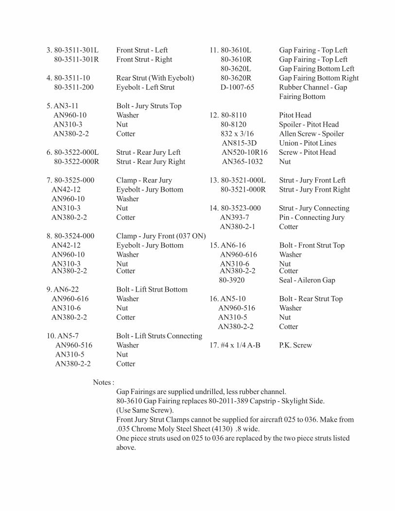
3. 80-3511-301L Front Strut - Left 11. 80-3610L Gap Fairing - Top Left 80-3511-301R Front Strut - Right 80-3610R Gap Fairing - Top Left
80-3620L Gap Fairing Bottom Left4. 80-3511-10 Rear Strut (With Eyebolt) 80-3620R Gap Fairing Bottom Right 80-3511-200 Eyebolt - Left Strut D-1007-65 Rubber Channel - Gap
Fairing Bottom5. AN3-11 Bolt - Jury Struts Top AN960-10 Washer 12. 80-8110 Pitot Head AN310-3 Nut 80-8120 Spoiler - Pitot Head AN380-2-2 Cotter 832 x 3/16 Allen Screw - Spoiler
AN815-3D Union - Pitot Lines6. 80-3522-000L Strut - Rear Jury Left AN520-10R16 Screw - Pitot Head 80-3522-000R Strut - Rear Jury Right AN365-1032 Nut
7. 80-3525-000 Clamp - Rear Jury 13. 80-3521-000L Strut - Jury Front Left AN42-12 Eyebolt - Jury Bottom 80-3521-000R Strut - Jury Front Right AN960-10 Washer AN310-3 Nut 14. 80-3523-000 Strut - Jury Connecting AN380-2-2 Cotter AN393-7 Pin - Connecting Jury
AN380-2-1 Cotter8. 80-3524-000 Clamp - Jury Front (037 ON) AN42-12 Eyebolt - Jury Bottom 15. AN6-16 Bolt - Front Strut Top AN960-10 Washer AN960-616 Washer AN310-3 Nut AN310-6 Nut AN380-2-2 Cotter AN380-2-2 Cotter
80-3920 Seal - Aileron Gap9. AN6-22 Bolt - Lift Strut Bottom AN960-616 Washer 16. AN5-10 Bolt - Rear Strut Top AN310-6 Nut AN960-516 Washer AN380-2-2 Cotter AN310-5 Nut
AN380-2-2 Cotter10. AN5-7 Bolt - Lift Struts Connecting AN960-516 Washer 17. #4 x 1/4 A-B P.K. Screw AN310-5 Nut AN380-2-2 Cotter
Notes :Gap Fairings are supplied undrilled, less rubber channel.80-3610 Gap Fairing replaces 80-2011-389 Capstrip - Skylight Side.(Use Same Screw).Front Jury Strut Clamps cannot be supplied for aircraft 025 to 036. Make from.035 Chrome Moly Steel Sheet (4130) .8 wide.One piece struts used on 025 to 036 are replaced by the two piece struts listedabove.
EMPENAGE
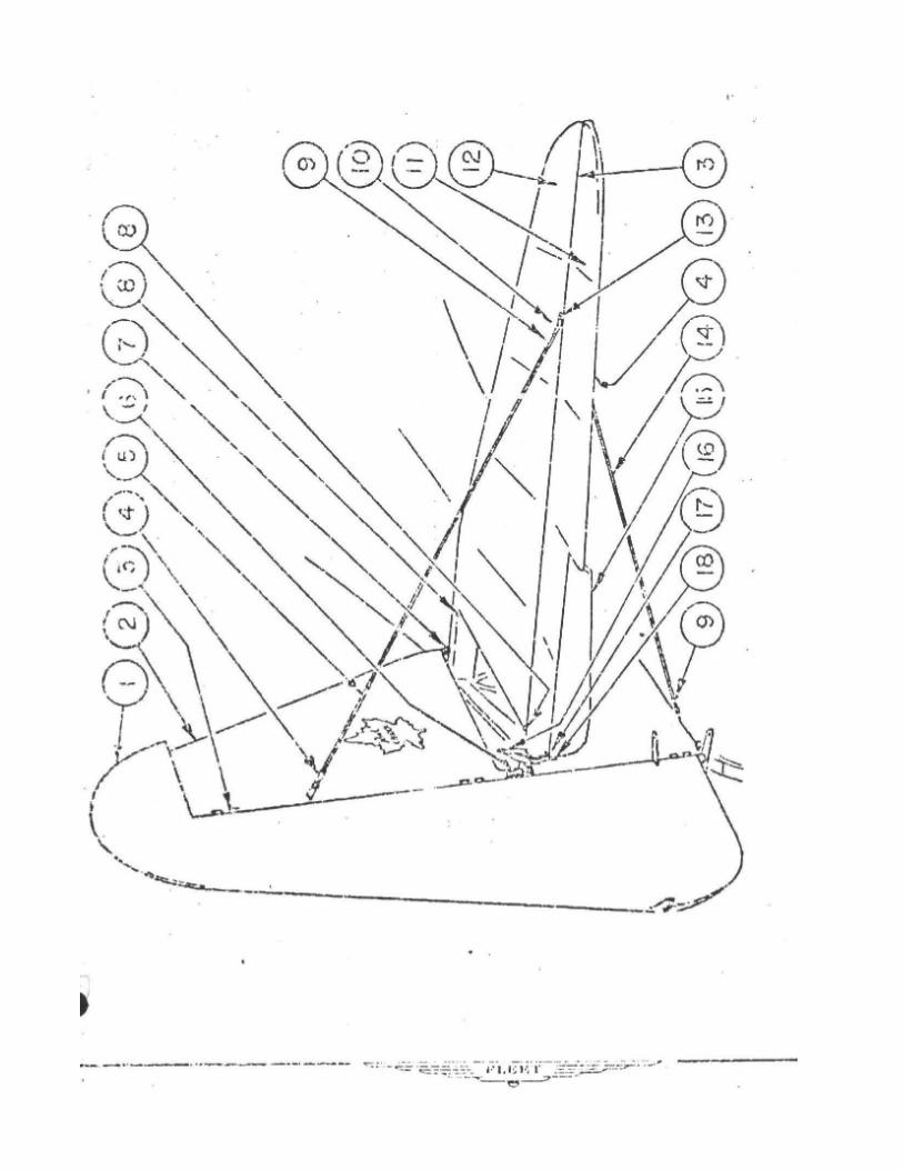
1. 80-4400 Rudder (Covered, with Navigation Light Bracket)2. 80-4201 Fin3. AN394-61 Pin
AN960-416L WasherAN380-2-2 Cotter
4. AN393-9 PinAN380-2-2 CotterAN665-10L TerminalAN315-640L Nut
5. AN671-4500 Tie Wire6. AN3-12 Bolt - Fin Rear7. AN3-7 Bolt - Fin Front8. AN4-13 Bolt - Stabilizer Attachements9. AN393-9 Pin
AN380-2-2 CotterAN315-640R NutAN665-10R Terminal
10. 80-4910 Bracket - Top80-4920 Bracket - Bottom
11. 80-4310L Elevator - Left80-4310R Elevator - Right (Less Tab)
12. 80-4100 Stabilizer13. AN4-13 Bolt14. AN671-4200 Tie Wire15. 80-4320 Tab16. AN3-3 Bolt - Elevators Connecting17. 80-4330 Bracket - Tab
AN3-7 Bolt - Tab Bracket18. 4SP4-B4 Cross Pin - Tab Control
AN380-2-1 CotterAN960-10L Washer
Rudder Travel Left 30deg. Right 30deg. +1.5deg.-1.5deg.
Elevator Travel Up 30deg. Down 20deg. +1.5deg.-1.5deg.
Tab Travel Up 20deg. Down 20deg. +5deg.-5deg.
Lock nuts on tie wires must not be tightened over 9 inch pounds, (3 pounds pressure on a 3 inch wrench)Wires can be easily strained by overtightening lock nuts.
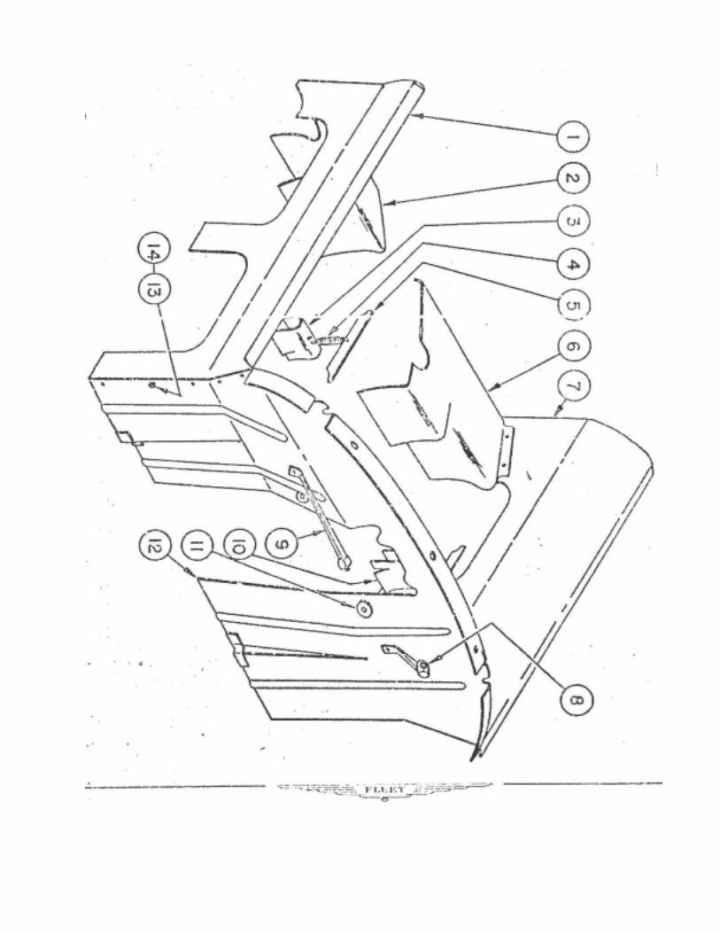
CABIN STRUCTURE
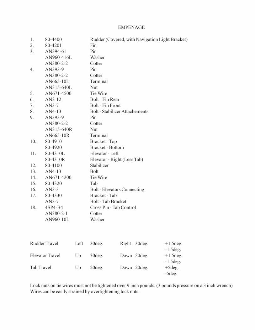
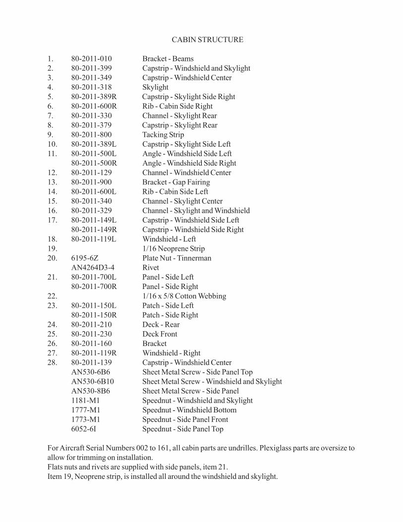
1. 80-2011-010 Bracket - Beams2. 80-2011-399 Capstrip - Windshield and Skylight3. 80-2011-349 Capstrip - Windshield Center4. 80-2011-318 Skylight5. 80-2011-389R Capstrip - Skylight Side Right6. 80-2011-600R Rib - Cabin Side Right7. 80-2011-330 Channel - Skylight Rear8. 80-2011-379 Capstrip - Skylight Rear9. 80-2011-800 Tacking Strip10. 80-2011-389L Capstrip - Skylight Side Left11. 80-2011-500L Angle - Windshield Side Left
80-2011-500R Angle - Windshield Side Right12. 80-2011-129 Channel - Windshield Center13. 80-2011-900 Bracket - Gap Fairing14. 80-2011-600L Rib - Cabin Side Left15. 80-2011-340 Channel - Skylight Center16. 80-2011-329 Channel - Skylight and Windshield17. 80-2011-149L Capstrip - Windshield Side Left
80-2011-149R Capstrip - Windshield Side Right18. 80-2011-119L Windshield - Left19. 1/16 Neoprene Strip20. 6195-6Z Plate Nut - Tinnerman
AN4264D3-4 Rivet21. 80-2011-700L Panel - Side Left
80-2011-700R Panel - Side Right22. 1/16 x 5/8 Cotton Webbing23. 80-2011-150L Patch - Side Left
80-2011-150R Patch - Side Right24. 80-2011-210 Deck - Rear25. 80-2011-230 Deck Front26. 80-2011-160 Bracket27. 80-2011-119R Windshield - Right28. 80-2011-139 Capstrip - Windshield Center
AN530-6B6 Sheet Metal Screw - Side Panel TopAN530-6B10 Sheet Metal Screw - Windshield and SkylightAN530-8B6 Sheet Metal Screw - Side Panel1181-M1 Speednut - Windshield and Skylight1777-M1 Speednut - Windshield Bottom1773-M1 Speednut - Side Panel Front6052-6I Speednut - Side Panel Top
For Aircraft Serial Numbers 002 to 161, all cabin parts are undrilles. Plexiglass parts are oversize toallow for trimming on installation.Flats nuts and rivets are supplied with side panels, item 21.Item 19, Neoprene strip, is installed all around the windshield and skylight.
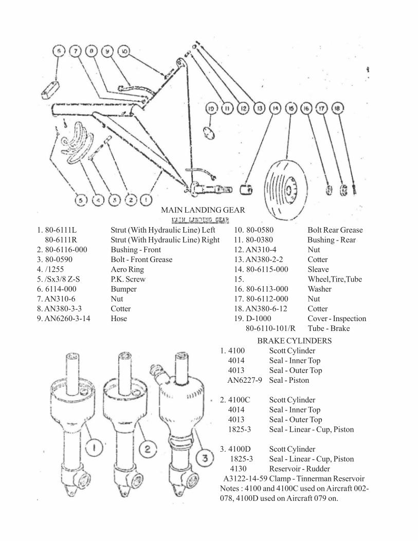
MAIN LANDING GEAR
1. 80-6111L Strut (With Hydraulic Line) Left 10. 80-0580 Bolt Rear Grease 80-6111R Strut (With Hydraulic Line) Right 11. 80-0380 Bushing - Rear2. 80-6116-000 Bushing - Front 12. AN310-4 Nut3. 80-0590 Bolt - Front Grease 13. AN380-2-2 Cotter4. /1255 Aero Ring 14. 80-6115-000 Sleave5. /Sx3/8 Z-S P.K. Screw 15. Wheel,Tire,Tube6. 6114-000 Bumper 16. 80-6113-000 Washer7. AN310-6 Nut 17. 80-6112-000 Nut8. AN380-3-3 Cotter 18. AN380-6-12 Cotter9. AN6260-3-14 Hose 19. D-1000 Cover - Inspection
80-6110-101/R Tube - BrakeBRAKE CYLINDERS
1. 4100 Scott Cylinder 4014 Seal - Inner Top 4013 Seal - Outer Top AN6227-9 Seal - Piston
2. 4100C Scott Cylinder 4014 Seal - Inner Top 4013 Seal - Outer Top 1825-3 Seal - Linear - Cup, Piston
3. 4100D Scott Cylinder 1825-3 Seal - Linear - Cup, Piston 4130 Reservoir - Rudder A3122-14-59 Clamp - Tinnerman ReservoirNotes : 4100 and 4100C used on Aircraft 002-078, 4100D used on Aircraft 079 on.

1. 510614 Ring - Bearing Retainer Goodyear 17. 510717-30 Brake Lining - Outer Goddyear2. 13889 Cone - Bearing - Timken 18. 511565-1 Pessure Plate - Goodyear3. 511430-N Wheel Half - Outboard Goodyear 19. AN6227-29 Seal4. 511475-M Wheel Half - Inboard Goodyear 20. 511563-M Piston - Goodyear5. 6-32x1/4 Type 1 Screw - Shakeproof 21. 9510253 Cylinder Head - Goodyear6. 3028-6 Lock Terminal - Shakeproof 22. NAS50-200 Lock Ring7. AN4-47A Bolt - 1/4 23. 511846-4 Washer - Aluminium Goodyear8. AN365-428 Nut 24. 10-24x5/16 Screw, Round Head9. AN960-416L Washer NC210. 530732-M Housing -Brake Goodyear 9520297 Brake Assembly (Less11. AN920-4D Union Disc)(Goodyear)12. AN902-4 Gasket 511413-M-1 Wheel Assembly (Less13. AN4-10 Bolt Hub Cap) (Goodyear)14. 510717-31 Brake Lining - Inner Goodyear 510612 Hub Cap - Goodyear15. 511918-1 Clip - Anti Rattle Goodyear AN515-6-4 Screw - Hub Cap16. 531058-1 Disc Goodyear AN936-A6 Lockwasher - Hub Cap
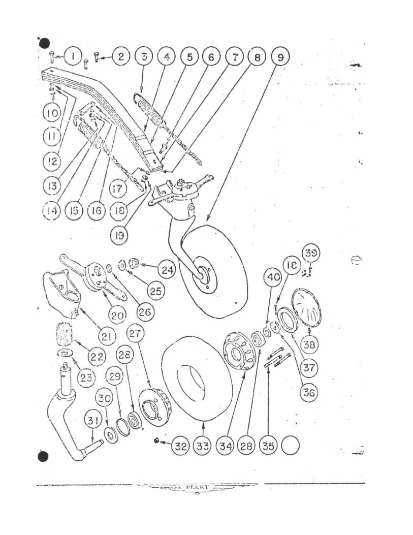
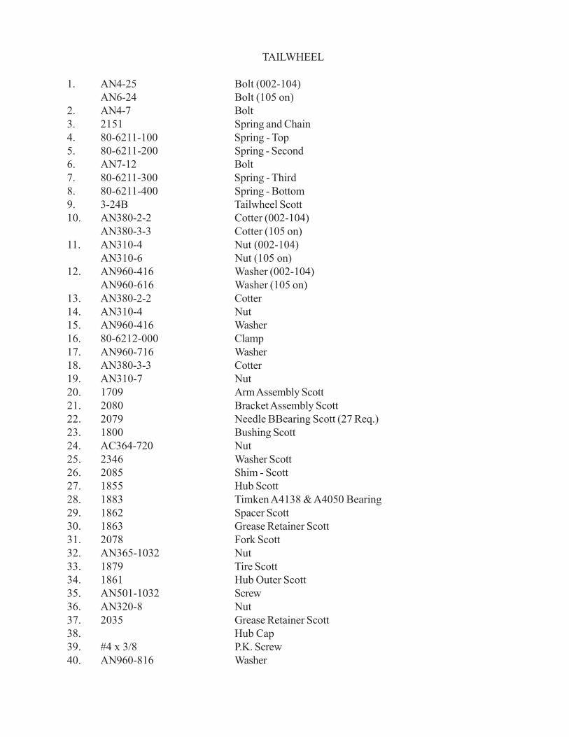
TAILWHEEL
1. AN4-25 Bolt (002-104)AN6-24 Bolt (105 on)
2. AN4-7 Bolt3. 2151 Spring and Chain4. 80-6211-100 Spring - Top5. 80-6211-200 Spring - Second6. AN7-12 Bolt7. 80-6211-300 Spring - Third8. 80-6211-400 Spring - Bottom9. 3-24B Tailwheel Scott10. AN380-2-2 Cotter (002-104)
AN380-3-3 Cotter (105 on)11. AN310-4 Nut (002-104)
AN310-6 Nut (105 on)12. AN960-416 Washer (002-104)
AN960-616 Washer (105 on)13. AN380-2-2 Cotter14. AN310-4 Nut15. AN960-416 Washer16. 80-6212-000 Clamp17. AN960-716 Washer18. AN380-3-3 Cotter19. AN310-7 Nut20. 1709 Arm Assembly Scott21. 2080 Bracket Assembly Scott22. 2079 Needle BBearing Scott (27 Req.)23. 1800 Bushing Scott24. AC364-720 Nut25. 2346 Washer Scott26. 2085 Shim - Scott27. 1855 Hub Scott28. 1883 Timken A4138 & A4050 Bearing29. 1862 Spacer Scott30. 1863 Grease Retainer Scott31. 2078 Fork Scott32. AN365-1032 Nut33. 1879 Tire Scott34. 1861 Hub Outer Scott35. AN501-1032 Screw36. AN320-8 Nut37. 2035 Grease Retainer Scott38. Hub Cap39. #4 x 3/8 P.K. Screw40. AN960-816 Washer
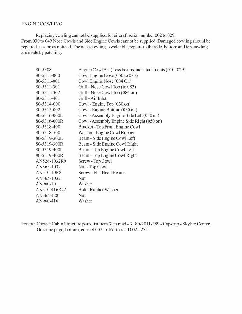
ENGINE COWLING
Replacing cowling cannot be supplied for aircraft serial number 002 to 029.From 030 to 049 Nose Cowls and Side Engine Cowls cannot be supplied. Damaged cowling should berepaired as soon as noticed. The nose cowling is weldable, repairs to the side, bottom and top cowlingare made by patching.
80-5308 Engine Cowl Set (Less beams and attachments (010 -029)80-5311-000 Cowl Engine Nose (050 to 083)80-5311-001 Cowl Engine Nose (084 On)80-5311-301 Grill - Nose Cowl Top (to 083)80-5311-302 Grill - Nose Cowl Top (084 on)80-5311-401 Grill - Air Inlet80-5314-000 Cowl - Engine Top (030 on)80-5315-002 Cowl - Engine Bottom (030 on)80-5316-000L Cowl - Assembly Engine Side Left (050 on)80-5316-000R Cowl - Assembly Engine Side Right (050 on)80-5318-400 Bracket - Top Front Engine Cowl80-5318-500 Washer - Engine Cowl Rubber80-5319-300L Beam - Side Engine Cowl Left80-5319-300R Beam - Side Engine Cowl Right80-5319-400L Beam - Top Engine Cowl Left80-5319-400R Beam - Top Engine Cowl RightAN526-1032R9 Screw - Top CowlAN365-1032 Nut - Top CowlAN510-10R8 Screw - Flat Head BeamsAN365-1032 NutAN960-10 WasherAN510-416R22 Bolt - Rubber WasherAN365-428 NutAN960-416 Washer
Errata : Correct Cabin Structure parts list Item 3, to read - 3. 80-2011-389 - Capstrip - Skylite Center. On same page, bottom, correct 002 to 161 to read 002 - 252.