cameron um bop ram
TRANSCRIPT

UM Blowout Preventer
Operation and Maintenance Manual
TC1542

All the information contained in this manual is the exclusive property ofCooper Cameron Corporation, Cameron Division. Any reproduction or useof the calculations, drawings, photographs, procedures or instructions,either expressed or implied, is forbidden without the written permission ofCameron or its authorized agent.
Initial Release A1
August 2002
Copyright © 2002 all rights reservedBy
Cooper Cameron CorporationCameron Division
TC1542 2

PREFACE
The procedures included in this book are to be performed in conjunction withthe requirements and recommendations outlined in API Specifications. Any re-pairs to the equipment covered by this book should be done by an authorizedCameron service representative. Cameron will not be responsible for loss or ex-pense resulting from any failure of equipment or any damage to any property orinjury or death to any person resulting in whole or in part from repairs per-formed by other than authorized Cameron personnel. Such unauthorized re-pairs shall also serve to terminate any contractual or other warranty, if any, onthe equipment and may also result in equipment no longer meeting applicablerequirements.
File copies of this manual are maintained. Revisions and/or additions will bemade as deemed necessary by Cameron. The drawings in this book are notdrawn to scale, but the dimensions shown are accurate.
This book covers Cameron UM Blowout Preventers, which are products ofCooper Cameron Corporation.
Cooper Cameron CorporationCameron DivisionP.O. Box 1212Houston, Texas 77251-1212713-939-2211http://www.coopercameron.com
TC1542 3

TC1542 4

Contents
Single Open-Face Flange or Studded UM BOP Dimensions . . . . . . . . 6
Double Open-Face Flange or Studded UM BOP Dimensions . . . . . . . 8
Single with Tandem Booster Dimensions . . . . . . . . . . . . . . . . . 10
Part Numbers . . . . . . . . . . . . . . . . . . . . . . . . . . . . . . . . 12
Tandem Boosters . . . . . . . . . . . . . . . . . . . . . . . . . . . . . . 18
Hydraulic Control System . . . . . . . . . . . . . . . . . . . . . . . . . . 20
Specifications and Accessories . . . . . . . . . . . . . . . . . . . . . . . 22
Ram Hang-Off Weights and Shear Requirements . . . . . . . . . . . . . 23
Pipe Rams . . . . . . . . . . . . . . . . . . . . . . . . . . . . . . . . . . 24
Shearing Blind Rams . . . . . . . . . . . . . . . . . . . . . . . . . . . . 28
Flexpackers . . . . . . . . . . . . . . . . . . . . . . . . . . . . . . . . . 31
CAMRAM™ 350 Packers and Top Seals . . . . . . . . . . . . . . . . . . 32
Bonnet Seals and Connecting Rod Seals . . . . . . . . . . . . . . . . . . 33
UM BOP Operation and Maintenance (T-275 ) . . . . . . . . . . . . . . 34
Bonnet Bolt Torque Requirements . . . . . . . . . . . . . . . . . . . . . 50
Recommended Torque for B-7 Cap Screws (EB 701D) . . . . . . . . . . . 51
TC1542 5

The capital letters in the following designations refer to the UM BOP dimensional views below and dimensional charts shown on thefollowing page.
A-1 Length - bonnets closed, locking screws lockedA-2 Length - bonnets opened, locking screws unlockedB-1 Height - flangedB-2 Height - studdedC Width - no side outletsD Centerline of preventer to outlet flange or hub face. This distance is variable and must be determined per individual specifications.E Centerline of side outlet to bottom flange faceF Top of ram to top flange faceG Height of ram
TC1542 6
UM BOP Assembly, Single
SD 034559
A
C
B
G
FE
D

TC1542 7
Single Open-Face Flange or Studded UM BOP Dimensions*
Size Pressure Rating(psi)
Vertical Bore(in) A-1 A-2 B-1 B-2 C E F G
Approx.Weight
(lb.)FlgXFlg
Approx.Weight
(lb.)StdXStd
7-1/16” 3000 7-1/16 78.250” 116.500” 24.062” 17” 20.250” 8.750” 7.844” 5.50” 2600 2477
7-1/16” 5000 7-1/16 78.250” 116.500” 27.500” 16.75” 20.250” 10.406” 9.625” 5.50” 2652 2477
7-1/16” 10,000 7-1/16 78.250” 116.500” 30.562” 15.50” 20.625” 11.062” 12.031” 5.50” 3275 2825
7-1/16” 15,000 7-1/16 78.250” 116.500” 31.812” 15.50” 20.625” 11.688” 12.656” 5.50” 3525 2825
11” 10,000 11 96.250” 146.875” 35.688” 16.63” 25.750” 13.125” 13.844” 6.75” 6400 9650
13-5/8” 10,000 13-5/8 134.500” 201.000” 41.688” 20.26” 30.250” 15.125” 17.094” 7.50” 10,300 10,300
Size Pressure Rating(psi)
Vertical Bore(cm)
A-1(cm)
A-2(cm)
B-1(cm)
B-2(cm)
C(cm)
E(cm)
F(cm)
G(cm)
Approx.Weight
(kg)FlgXFlg
Approx.Weight
(kg)StdXStd
7-1/16” 3000 17.9 199 296 61 43 51 22 20 14 1179 1124
7-1/16” 5000 17.9 199 296 70 43 51 26 24 14 1203 1124
7-1/16” 10,000 17.9 199 296 78 39 53 28 31 14 1486 1281
7-1/16” 15,000 17.9 199 296 81 39 53 30 32 14 1599 1281
11” 10,000 27.9 244 373 91 42 65 33 35 17 2903 2903
13-5/8” 10,000 34.6 342 511 106 51 77 38 43 19 4672 4377
*Available with Stud X Flange Connections.

The capital letters in the following designations refer to the UM BOP dimensional views below and dimensional charts shown on thefollowing page.
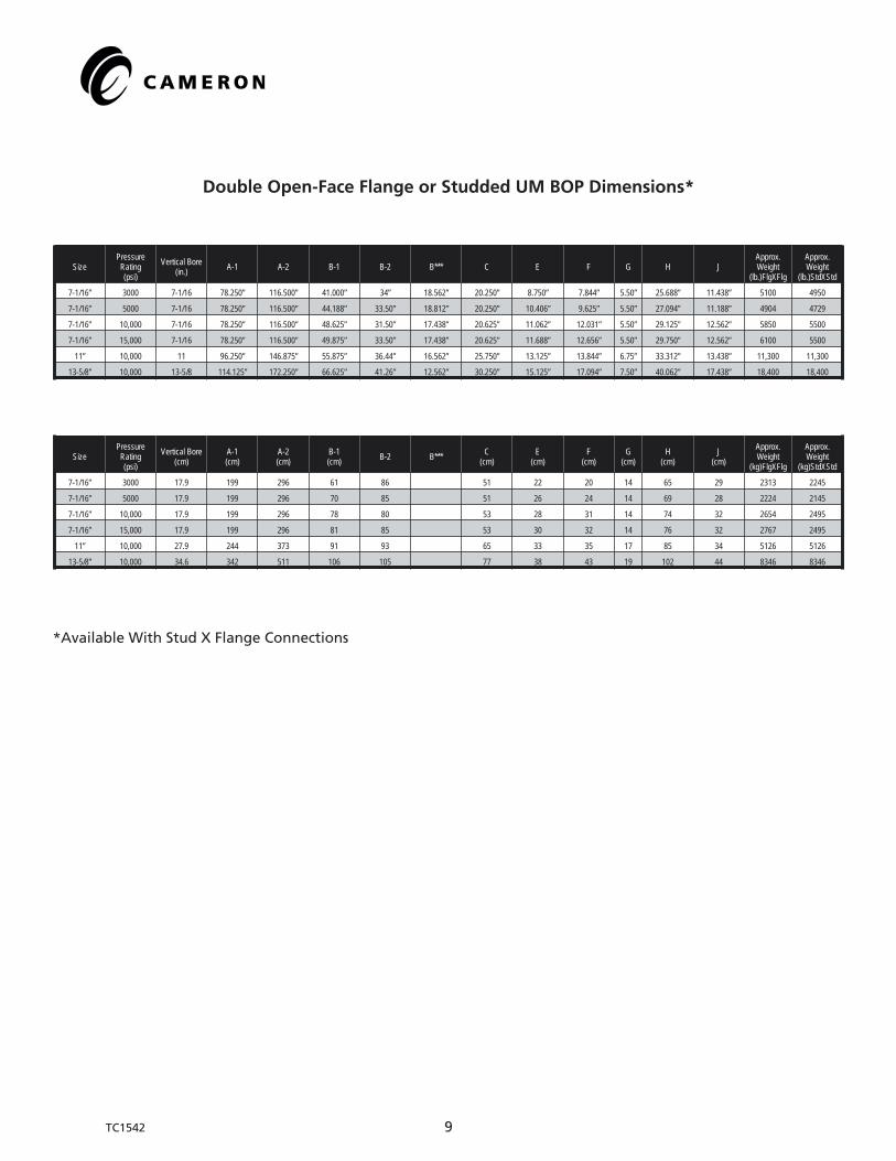
A-1 Length - bonnets closed, locking screws lockedA-2 Length - bonnets opened, locking screws unlockedB-1 Height - flangedB-2 Height - studdedB*** Height - with 30” spacerC Width - no side outletsD Centerline of preventer to outlet flange or hub face. This distance is variable and must be determined per individual specifications.E Centerline of side outlet below rams to bottom flange faceF Top of upper ram to top flange faceG Height of ramH Centerline of side outlet between rams to bottom flange faceJ Top of lower ram to bottom of upper ram
UM BOP Assembly, Double
SD 034560
C
B
G
J
EHF
D
A
TC1542 8
TC1542 9
Double Open-Face Flange or Studded UM BOP Dimensions*
SizePressureRating(psi)
Vertical Bore(in.) A-1 A-2 B-1 B-2 B*** C E F G H J
Approx.Weight
(lb.)FlgXFlg
Approx.Weight
(lb.)StdXStd
7-1/16” 3000 7-1/16 78.250” 116.500” 41.000” 34” 18.562” 20.250” 8.750” 7.844” 5.50” 25.688” 11.438” 5100 4950
7-1/16” 5000 7-1/16 78.250” 116.500” 44.188” 33.50” 18.812” 20.250” 10.406” 9.625” 5.50” 27.094” 11.188” 4904 4729
7-1/16” 10,000 7-1/16 78.250” 116.500” 48.625” 31.50” 17.438” 20.625” 11.062” 12.031” 5.50” 29.125” 12.562” 5850 5500
7-1/16” 15,000 7-1/16 78.250” 116.500” 49.875” 33.50” 17.438” 20.625” 11.688” 12.656” 5.50” 29.750” 12.562” 6100 5500
11” 10,000 11 96.250” 146.875” 55.875” 36.44” 16.562” 25.750” 13.125” 13.844” 6.75” 33.312” 13.438” 11,300 11,300
13-5/8” 10,000 13-5/8 114.125” 172.250” 66.625” 41.26” 12.562” 30.250” 15.125” 17.094” 7.50” 40.062” 17.438” 18,400 18,400
SizePressureRating(psi)
Vertical Bore(cm)
A-1(cm)
A-2(cm)
B-1(cm) B-2 B*** C
(cm)E
(cm)F
(cm)G
(cm)H
(cm)J
(cm)
Approx.Weight
(kg)FlgXFlg
Approx.Weight
(kg)StdXStd
7-1/16” 3000 17.9 199 296 61 86 51 22 20 14 65 29 2313 2245
7-1/16” 5000 17.9 199 296 70 85 51 26 24 14 69 28 2224 2145
7-1/16” 10,000 17.9 199 296 78 80 53 28 31 14 74 32 2654 2495
7-1/16” 15,000 17.9 199 296 81 85 53 30 32 14 76 32 2767 2495
11” 10,000 27.9 244 373 91 93 65 33 35 17 85 34 5126 5126
13-5/8” 10,000 34.6 342 511 106 105 77 38 43 19 102 44 8346 8346
*Available With Stud X Flange Connections

The capital letters in the following designations refer to the UM BOP dimensional views below and dimensional charts shown on thefollowing page.
A-1 Length - bonnets closed, locking screws lockedA-2 Length - bonnets opened, locking screws unlockedB-1 Height - flangedB-2 Height - studdedC Width - no side outletsD Centerline of preventer to outlet flange or hub face. This distance is variable and must be determined per individual specifications.E Centerline of side outlet to bottom flange faceF Top of ram to top flange faceG Height of ram
UM BOP Assembly, Single with Tandem Boosters
SD 034566
A
C
B
EF
G
D
TC1542 10
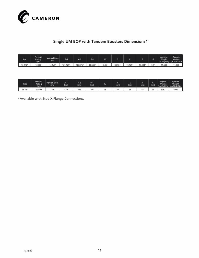
Single UM BOP with Tandem Boosters Dimensions*
SizePressureRating(psi)
Vertical Bore(in)
A-1 A-2 B-1 B-2 C E F GApprox.Weight
(lb.)FlgXFlg
Approx.Weight
(lb.)StdXStd
13-5/8” 10,000 13-5/8” 169.125” 235.875” 41.688” 30.88” 30.50” 15.125” 17.094” 7.5” 11,600 11,000
SizePressureRating(psi)
Vertical Bore(cm)
A-1(cm)
A-2(cm)
B-1(cm)
B-2 C(cm)
E(cm)
F(cm)
G(cm)
Approx.Weight
(kg)FlgXFlg
Approx.Weight
(kg)StdXStd
13-5/8” 10,000 34.6 430 599 106 78 77 38 43 19 5262 4990
*Available with Stud X Flange Connections.
TC1542 11

TC1542 12
UM BOP, 7-1/16”
SD 034510
3123
3143
36
3537
533
3440
2622
3920
3824
25
36
50
2
1918
1621
54
55
1
44 1213 11 10
51
2728
29
3433
437
635
53
52
67
56
1514 17
66

TC1542 13
7-1/16” UM Blowout Preventer Part Numbers
Item No. Description Qty - Single Qty - Double7-1/16”5000 psiModel II
7-1/16”10,000 psiModel II
7-1/16”15,000 psiModel II
1 Body 1 1 ---- ---- ----
2 Bonnet 2 4 2010585-01 2010584-01 2010515-03
3 Operating Piston 2 4 2010559-02 2010559-01 2010559-01
4 Ram Change Piston, Open 2 4 2011075-01 2011075-01 2011075-01
5 Ram Change Piston, Close 2 4 2011073-01 2011073-01 2011073-01
6 Ram Change Cylinder 4 8 2011074-01 2011074-01 2011074-01
10 Pin, Ram Guide 4 8 030313-02 030313-02 030313-02
11 Check Valve 2 4 M517988 M517988 M517988
12 Screw, Socket Head Set 2 4 005940-09 005940-09 005940-09
13 Pipe Plug, Heavy Hex Head 2 4 005930-05-10 005930-05-10 005930-05-10
14 Retainer Ring, Plastic Packing 2 4 2010178-01 2010178-01 2010178-01
15 Energizing RIng 2 4 018586-12 018586-12 018586-12
16 Lip Seal 2 4 212741-37 212741-37 212741-37
17 O-Ring 2 4 018492-92 018492-92 018492-92
18 Retainer, Lip Seal 2 4 689523-04 689523-04 689523-04
19 Retaining Ring, Spirolox 2 4 018572-83 018572-83 018572-83
20 Locking Screw 2 4 2010519-01 2010519-01 2010519-01
21 Ring Gasket 4 8 ---- 021792-21 ----
22 Locking Screw Housing 2 4 2010530-01 2010530-01 2010530-01
23 Operating Cylinder 2 4 2010529-02 2010529-02 2010529-02
24 Cylinder Head Weldment 2 4 2011328-01 2011328-01 2011328-01
25 Stud, Double Ended 8 16 2010189-19 2010189-19 2010189-19
26 Nut, Heavy Hex 8 16 2709000-13-01 2709000-13-01 2709000-13-01
27 Seal Ring 2 4 2708749-01 2708749-01 2708749-01
28 Retainer Ring, Tail Rod 2 4 2010527-01 2010527-01 2010527-01
29 Retaining Ring, Spirolox 2 4 041008-02-93-32 041008-02-93-32 041008-02-93-32
30 Seal RIng 2 4 2710280 2710280 2710280
31 O-Ring 4 8 702645-37-61 702645-37-61 702645-37-61
32 O-Ring 2 4 702645-26-91 702645-26-91 702645-26-91
33 Seal RIng 4 8 2724047 2724047 2724047
34 Wear Ring, Ram Change Piston 4 8 049223-28 049223-28 049223-28
35 O-Ring 8 16 702645-33-71 702645-33-71 702645-33-71
36 O-Ring 4 8 702645-32-81 702645-32-81 702645-32-81
37 O-Ring 8 16 702645-32-41 702645-32-41 702645-32-41
38 Stud, Double Ended 16 32 ---- 219065-08-03-61 219065-08-03-61
39 Nut, Heavy Hex 16 32 ---- 2709000-08-01 2709000-08-01
40 Lifting Eye 4 8 011849 011849 011849
41 Split Retainer Ring 2 4 2010599-01 2010599-01 2010599-01
42 Concentric Booster Ring 2 4 2010600-01 2010600-01 2010600-01
43 Seal Ring 2 4 710541 710541 710541
44 Plastic Packing 10 20 007650-08 007650-08 007650-08
46 Blind Plug 4 8 017454-09 ---- 017454-09
47 Pipe Plug 4 8 002504-04 ---- 002504-04
48 Tubing Gland 4 8 017454-08 ---- 017454-08
66 Name Plate 1 1 2032175-03 2032175-01 ----
67 Name Plate 1 ---- 025950 025950 ----
50 Bonnet Bolt 8 16 2010514-02 2010514-03 ----
51 Bonnet Seal (Carrier Type) 4 8 ---- ---- ----
51A Bonnet Seal (Face Type) 2 4 644197-01-00-01 644197-01-00-01 644197-01-00-01
52 Stud, Double Ended 12 ---- ---- 219067-14-07-41 ----
53 Nut, Heavy Hex 12 ---- ---- 2709000-14-01 ----
54 Stud, Double Ended 16 ---- ---- 219067-08-03-61 ----
55 Nut, Heavy Hex 16 ---- ---- 2709000-08-01 ----
56 Name Plate 1 1 ---- 236606-01 ----
66 Name Plate 1 1 2032175-03 2032175-01 ----
67 Name Plate 1 ---- 025950 025950 ----
Accessory Items
Ram Change Piston Cover 2 4 645046-17 645046-17 645046-17
Standard Accessory Items 1 1 697149-01 697149-02 697149-02
Locking Screw Accessory Items 2 4 ---- 697150-01 697150-01
Expendable Items
Ring Gasket 2 4 702002-03-52 702003-15-22 702003-15-22
Ring Gasket 2 4 702002-04-62 702003-15-62 702003-15-62

TC1542 14
UM BOP, 11”
SD 034498
2123
216
3335
30
3228
435
633
528
3238
2622
313
17
2436
2037
25 40 42 278
1062
1514
17
86 87
34
5274 41 29
12 13
11
1918
1643
1

11” UM Blowout Preventer Part Numbers
Item No. Description Qty - Single Qty - Double 11”3000 psi
11”5000 psi
11”10,000 psi
11”15,000 psi
1 Body 1 1 ---- ---- ---- ----
2 Bonnet (Seal Carrier) 2 4 ---- ---- ---- ----
2A Bonnet (Face Seal) 2 4 ---- 2011152-01 2164126-01 ----
3 Piston Subassembly 2 4 ---- 2011173-01 2011173-01 ----
4 Ram Change Piston - Open 2 4 ---- 2011155-01 2011155-01 ----
4A Ram Change Piston - Open, Special ---- ---- ---- ---- ---- ----
5 Ram Change Piston - Close 2 4 ---- 2011144-01 2011144-01 ----
5A Ram Change Piston - Close, Special ---- ---- ---- ---- ---- ----
6 Ram Change Cylinder 4 8 ---- 2011154-01 2011154-01 ----
8 O-Ring ---- ---- ---- ---- ---- ----
9 Ram Change Piston Cap ---- ---- ---- ---- ---- ----
10 Ram Guide Pin 4 8 ---- 030313-03 030313-03 ----
11 Check Valve 2 4 ---- M517988 M517988 ----
12 Set Screw, Socket Head 2 4 ---- 005940-09 005940-09 ----
13 Pipe Plug 2 4 ---- 005930-05-10 005930-05-10 ----
14 O-Ring 2 4 ---- 2010178-02 2010178-02 ----
15 Energizing Ring 2 4 ---- 018586-13 018586-13 ----
16 Lip Seal 2 4 ---- 212741-38-00-01 212741-38-00-01 ----
17 O-Ring 6 12 ---- 018492-91 018492-91 ----
18 Retainer, Lip Seal 2 4 ---- 689523-05 689523-05 ----
19 Retaining Ring, Spirolox 2 4 ---- 018572-84 018572-84 ----
20 Locking Screw 2 4 ---- 046628-01 046628-01 ----
21 O-Ring 4 8 ---- 702645-38-21 702645-38-21 ----
22 Locking Screw Housing 2 4 ---- 2011168-01 2011168-01 ----
23 Operating Cylinder 2 4 ---- 2011172-01 2011172-01 ----
24 Cylinder Head Weldment 2 4 ---- 2011167-01 2011167-01 ----
25 Stud, Double Ended 8 16 ---- 219065-17-20-01 219065-17-20-01 ----
26 Nut 8 16 ---- 2164777-01 2164777-01 ----
28 O-Ring 4 8 ---- 702645-33-31 702645-33-31 ----
29 Plastic Packing 10 20 ---- 007650-25 007650-25 ----
30 Seal Ring 2 4 ---- 2724061 2724061 ----
31 Wear Ring 2 4 ---- 049223-31 049223-31 ----
32 Wear Ring 4 8 ---- 049223-32 049233-32 ----
33 O-Ring 8 16 ---- 702645-33-91 702645-33-91 ----
34 O-Ring 4 8 ---- 702645-33-01 702645-33-01 ----
35 O-Ring 8 16 ---- 702645-32-61 702645-32-61 ----
36 Stud, Double Ended 16 32 ---- 219065-12-05-01 219065-12-05-01 ----
37 Nut 16 32 ---- 2709000-12-01 2709000-12-01 ----
38 Lifting Eye 2 4 ---- 011849 011849 ----
40 Blind Plug 4 8 ---- 017454-09 017454-09 ----
41 Plug, Pipe, Threaded 4 8 ---- 002504-04 002504-04 ----
42 Tubing Gland 4 8 ---- 017454-08 017454-08 ----
43 Ring Gasket 4 8 ---- 021792-22 021792-22 ----
52 Bonnet Bolt 8 16 ---- 2010962-01 2164128-01 ----
62 Bonnet Seal 4 8 ---- ---- ---- ----
62A Bonnet Seal (Face Type) 2 4 ---- 644197-02-00-01 644197-02-00-01 ----
74 O-Ring 8 16 ---- 702645-22-91 702645-22-91 ----
78 Lifting Eye 2 2 ---- 011849 011849 ----
96 Name Plate 1 1 ---- 2032175-03 2032175-03 ----
97 Name Plate 1 1 ---- 025950 025950 ----
Accessory Items
Standard Accessories 1 1 ---- 697149-02 697149-02 ----
Locking Screw Accessories 2 4 ---- 697150-02 697150-02 ----
Cover, Ram Change Pistons 2 2 ---- 645046-18 645046-18 ----
Expendable Items
Ring Gaskets (Top & Bottom Conn.) 2 2 ---- 702002-05-42 702003-15-82 ----
TC1542 15

TC1542 16
UM BOP, 13-5/8”
SD034538
39
29
12
2632
1112
4312
14
43
1443
2442
4111
25
1443
4340
1619
1718
513
2827
1412
11
330
5033
1143
402
4241
75
1
66
65
64
71
70
74
76
1078
22
2045
98
355
4
3736
636
3123
3138
15
See Detail“A”
Detail “A”

13-5/8” UM Blowout Preventer Part Numbers
Item No. Description Qty - Single Qty - Double 13-5/8”5000 psi
13-5/8”10,000 psi
13-5/8”15,000 psi
1 Body 1 1 ---- ---- ----2 Bonnet (Seal Carrier) 2 4 ---- 2164340-01(02) ----2A Bonnet (Face Seal) 2 4 ---- 2164343-01(02) ----3 Piston Subassembly (2) (4) ---- 2164345-01 ----4 Ram Change Piston - Open 2 4 ---- 2164433-02 ----4A Ram Change Piston - Open, Special 2 4 ---- 2164433-01 ----5 Ram Change Piston - Close 2 4 ---- 2164434-02 ----5A Ram Change Piston - Close, Special 2 4 ---- 2164434-01 ----6 Ram Change Cylinder 4 8 ---- 2164347-02 ----6A Ram Change Cylinder, Special 4 8 ---- 2164347-01 ----8 O-Ring 4 8 ---- 702645-35-71 ----9 Ram Change Piston Cap 4 8 ---- 2164342-02 ----9A Ram Change Piston Cap, Special 4 8 ---- 2164342-01 ----10 Ram Guide Pin 4 8 ---- 030313-01 ----11 Retainer Ring, Spirolox, Operating Piston 8 16 ---- 708758 ----12 Retainer, Polypak 8 16 ---- 689523-06 ----14 Seal Polypak 8 16 ---- 2724613-01 ----15 Wear Ring, Ram Change Piston 4 8 ---- 2164449-01 ----16 Check Valve 2 4 ---- M517988 ----17 Screw, Socket Head 2 4 ---- 005940-09 ----18 Pipe Plug 2 4 ---- 005930-05-10 ----19 Packing, Plastic 2 4 ---- 007650-25 ----20* Locking Screw 2 4 ---- 695234 ----22* Locking Screw Housing 2 4 ---- 2164346-01 ----23 Operating Cylinder 2 4 ---- 2164348-02 ----23 Operating Cylinder, Special 2 4 ---- 2164348-01 ----24 Cylinder Head 2 4 ---- 2164341-02 ----24 Cylinder Head, Special 2 4 ---- 2164341-01 ----25 Cylinder Stud 24 48 ---- 2164361-01 ----26 Nut, Cylinder 24 48 ---- 2709000-12-22 ----27 Retainer Ring, Plastic Packing 2 4 ---- 012469-24 ----28 Energizing Ring 2 4 ---- 018586-01 ----29 Wear Ring, Operating Piston 2 4 ---- 049223-31 ----30 Seal Ring 2 4 ---- 2724061 ----31 O-Ring 4 8 ---- 702645-38-21 ----32 Washer, Cylinder Stud 24 48 ---- K220607 ----33 Washer, Bonnet Bolt 8 16 ---- 2164450-01 ----35 O-Ring 4 8 ---- 702645-33-81 ----36 O-Ring 8 16 ---- 702645-34-61 ----37 O-RIng 8 16 ---- 702645-32-41 ----37A O-RIng, Special for V Threaded Ram Change Piston 8 16 ---- 702645-32-81 ----38 O-Ring 4 8 ---- 702645-33-31 ----39* Screw 16 32 ---- 702585-25-00-30 ----40 Lifting Eye 4 8 ---- 011849 ----41 Tubing Gland 4 8 ---- 017454-08 ----42 Blind Plug 4 8 ---- 017454-09 ----43 Pipe Plug, Pressure 12 24 ---- 002504-14 ----45 Pipe Plug, Threaded 4 8 ---- 203682 ----50 Bonnet Bolt 8 16 ---- 2164362-01 ----51 O-Ring 8 16 ---- 2164718-01 ----64 Name Plate 1 1 ---- 025950 ----65 Name Plate 1 1 ---- 2032175-03 ----66 Name Plate 1 1 ---- 236606-01 ----70 Lifting Lug 2 2 ---- 2164420-01 ----71 Screw, Cap 8 8 ---- 702546-31-00-34 ----74 Stud, Top End Connection 20 20 ---- 219065-17-10-71 ----75 Nut, Top End Connection 20 20 ---- 2709000-17-01 ----76 Pipe Plug 2 4 ---- 201019 ----77 Bonnet Seal Carrier 2 4 ---- 645507-01-00-01 ----78 Bonnet Seal (for Carrier) 4 8 ---- 645509-01-00-01 ----78A Bonnet Seal (Face Type) (2) (4) ---- 644197-03-00-01 ----79 O-Ring 2 4 ---- 702645-56-91 ----
80** Tandem Booster Assembly (Qty. 1 for 2 Bonnets) 1 1 ---- 2164649-01 ----Accessory Items
Standard Accessories 1 1 ---- 697149-12 ----Locking Screw Accessories 2 4 ---- 697150-02 ----Spanner Wrench 1 1 ---- 2164429-01 ----
Expendable ItemsRing Gaskets (Top & Bottom Connection) 2 2 ---- 702003-15-92 ----Eyebolt 2 2 ---- 700734 ----Paste 1 1 ---- 705444 ----Loctite Adhesive 1 1 ---- 708740 ----Thread Sealant 1 1 ---- 711706 ----
*Not Required When Using Wedgelocks or Tandem Boosters
**Optional Tandem Boosters
TC1542 17

TC1542 18
Tandem Booster Assembly
SD 034536
16
1
7
17
5
13
12
6
15
14
3
11
10
9
2423
4
29
25
29
28
30
8
26
27

Tandem Boosters for UM BOPs
A BOP equipped with tandem boosters can deliver increased shearing force while not in-creasing the wear and tear on the packers. Tandem boosters approximately double theforce available to shear pipe. Since the tailrod of the tandem booster has the same strokeas the BOP’s operating piston, the standard shear locking mechanism can be installed onthe outside end of the booster. For information on lock screws and the required spacers,see page 17.
For information concerning applications where a tandem booster is required, consultyour Cameron representative.
Item Number Description Qty. Part Number13-5/8” 10,000 psi WP
1 Adapter 2 2164650-01
3 Cylinder 2 2010884-01
4 Cylinder Head 2 2010882-02
5 Tail Rod 2 2010880-01
6 Piston 2 645172-03
7 Screw, 12 Pt Cap 16 702585-25-00-30
8 Screw, 12 Pt Cap 12 702585-34-01-54
9 O-Ring 2 702645-33-71
10 Seal, Lip 2 011741-34
11 O-Ring 2 702645-38-12
12 Seal Ring 2 710418
13 Wear Ring 2 645215-01
14 Wear Ring 2 049223-01
15 Seal Ring 2 704772
16 Filter, Muffler, Quiet Flow 2 2724042
17 Stud, Continuous Thread 2 702533-09-10-22
23 Gland, Tubing 2 017454-08
24 Blind Plug 2 017454-09
25 Plug, Pipe-Threaded Hex Socket 2 002504-28
26 Tubing, Hydraulic 2 2711865-12-11
27 Bushing, Pipe 2 K194489
28 Bushing, Pipe 2 203098
29 Connector, Tubing, Male 4 204887-08-05-17
30 Elbow, 90 Degree, Male 2 204890-08-05-17
TC1542 19

SD 034582
PipeBonnet
ShearBonnet
ClosePressure
TandemStandard
OpenPressure
UM BOP Open and Close Hydraulics(13-5/8” 10,000 Shown)
PipeBonnet
ShearBonnet
ClosePressure
OpenPressure
TC1542 20

UM BOP Operating Data and Fluid Requirements
Bore Size andWorking Pressure
Gals to Open Pipe Rams(1 set)
Gals to Close Pipe Rams(1 set)
Gals to Close Shear Rams(1 set)
Closing Area(Sq. inches)
Locking Screw Turns(Each End)
ClosingRatio
OpeningRatio
7-1/16” All WP 2.2 2.3 2.4 67.3 18 11.7:1 3.8:1
11” Except15,000 psi 6.2 6.2 7.4 113.8 27 13.7:1 3.7:1
11” 15,000 psi - - - - - - -
13-5/8” Except15,000 psi 7.5 7.5 8.8 110.15 32 8.7:1 2.3:1
13-5/8” 15,000 psiModel B - - - - - - -
Bore Size andWorking Pressure
Liters to Open Pipe Rams(1 set)
Liters to Close Pipe Rams(1 set)
Liters to Close Shear Rams(1 set)
Closing Area(Sq. cm)
Locking Screw Turns(Each End)
ClosingRatio
OpeningRatio
7-1/16” All WP 8.3 8.7 9.1 434 18 11.7:1 3.8:1
11” Except15,000 psi 23.5 23.5 28.0 734 27 13.7:1 3.7:1
11” 15,000 psi - - - - - - -
13-5/8” Except15,000 psi 28.4 28.4 33.3 711 32 8.7:1 2.3:1
13-5/8” 15,000 psiModel B - - - - - - -
UM BOP Tandem Booster Operating Data and Fluid Requirements*
Bore Size andWorking Pressure
Gals to Open Pipe Rams(1 set)
Gals to Close Pipe Rams(1 set)
Closing Area(Sq. inches)
Locking Screw Turns(Each End)
Closing Ratio Opening Ratio
7-1/16” All WP - - - - - 3.8:1
11” Except15,000 psi 6.2 13.1 201.8 27 24.3:1 3.7:1
11” 15,000 psi - - - - - -
13-5/8” Except15,000 psi 7.5 10.4 198 32 15.6:1 2.3:1
13-5/8” 15,000 psiModel B - - - - - -
*All volumes based on shear ram configuration
Bore Size andWorking Pressure
Liters to Open Pipe Rams(1 set)
Liters to Close Pipe Rams(1 set)
Closing Area(Sq. cm)
Locking Screw Turns(Each End)
Closing Ratio Opening Ratio
7-1/16” All WP - - - - - 3.8:1
11” Except15,000 psi 23.5 49.6 1302 27 24.3:1 3.7:1
11” 15,000 psi - - - - - -
13-5/8” Except15,000 psi 28.4 39.4 1277 32 15.6:1 2.3:1
13-5/8” 15,000 psiModel B - - - - - -
*All volumes based on shear ram configuration
TC1542 21

UM BOP Specifications and Accessories
The following specifications apply to typical Cameron UM type BOPs. Your Cameron rep-resentative can provide information on non-standard BOP assemblies.
• Side outlets to 4-1/16” can be provided beneath each set of rams on either or bothsides of UM BOPs. Side outlets can be studded, open-face flange or clamp hub withthe same pressure rating as the vertical run connections.
• Flanges conform to API standard 6A and/or 16A. Hubs conform to API 16A orapplicable standards. Type 6BX flanges are standard for 10,000 and 15,000 psiworking pressures and for 5000 psi for 13-5/8” BOPs.
• Hydraulic control connections for operation of rams and bonnets are 1” NPT. Thereare two connections for each set of rams.
UM BOP Standard Accessories
Size and Working Pressure Ram Lube* Cameron Box Wrench* Allen Wrench* PackingScrew Handwheel** Universal Joint** Extension Wrench*
7-1/16” 3000 psi 713878 713114-08 8721-01 5457 6018-01 5652
7-1/16” 5000 psi 713878 7957-06 8721-01 5457 6018-01 5652
7-1/16” 10,000 and 15,000 psi 713878 713114-10 8721-01 5457 6018-01 5652
11” 3000, 5000 and 10,000 psi 713878 713114-10 8721-01 5298 6018-03 5526
11” 15,000 psi 713878 713114-13 8721-01 5298 6018-03 5526
13-5/8” 3000 and 5000 psi 713878 7959-08 8721-01 5298 6018-03 5526
13-5/8” 10,000 psi 713878 713114-10 8721-01 5298 6018-03 5526
13-5/8” 15,000 psi 713878 *** 8721-01 5298 6018-03 5526
*One required. **Two required for single preventer, four for double preventer. ***Commercially available sockets are recommended.
TC1542 22

UM BOP Ram Hang-Off Weights andShear Requirements
Hang-Off Weights
Hang-off weights are estimated capacities with hardened top corners of the hang-offrams. This enables the rams to dig into the tool joint and provide superior hang-off capac-ity while still meeting NACE requirements.
For variable bore rams (VBRs) and FLEXPACKER rams, hang-off weights up to 300,000lb (136,078 kg) on hang-off rams for the lower pipe size in the range, 600,000 lb (272,155kg) for the larger pipe size in the range.
Drill Pipe Shearing Requirements
The minimum shearing configurations needed for each size UM BOP to meet the require-ments of the second edition of API 16A are listed in the following chart. Each shearingconfiguration is capable of shearing the corresponding pipe at a closing pressure equal toor less than 2800 psi. For further information on shearing requirements for different pipesizes and grades, contact your Cameron representative.
Minimum Shearing Configurations for the UM BOP
API Designated Size Ram Type Pressure Rating (psi) Pipe OD (In.) Pipe lb/ft Pipe Grade Shearing Configuration
7-1/16” SBR All 3-1/2 13.3 S Shear Bonnets with Tandem Boosters
11” SBR 10,000 and Lower 5 19.5 E Shear Bonnets with Tandem Boosters
11” DS 10,000 and Lower 5 19.5 E Large Bore Shear Bonnets
11” SBR 15,000 and Higher 5 19.5 G Large Bore Shear Bonnets
13-5/8” SBR 10,000 and Lower 5 19.5 G Shear Bonnets with Tandem Boosters
13-5/8” DS 10,000 and Lower 5 19.5 G Large Bore Shear Bonnets
13-5/8” SBR 15,000 and Higher 5 19.5 S Large Bore Shear Bonnets
Note: See page 19 for a complete list of part numbers for the ltandem boosters.
TC1542 23
TC1542 24
SD 017508
Top Seal
Ram Packer
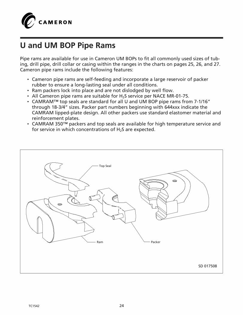
U and UM BOP Pipe Rams
Pipe rams are available for use in Cameron UM BOPs to fit all commonly used sizes of tub-ing, drill pipe, drill collar or casing within the ranges in the charts on pages 25, 26, and 27.Cameron pipe rams include the following features:
• Cameron pipe rams are self-feeding and incorporate a large reservoir of packerrubber to ensure a long-lasting seal under all conditions.
• Ram packers lock into place and are not dislodged by well flow.• All Cameron pipe rams are suitable for H2S service per NACE MR-01-75.• CAMRAM™ top seals are standard for all U and UM BOP pipe rams from 7-1/16”
through 18-3/4” sizes. Packer part numbers beginning with 644xxx indicate theCAMRAM lipped-plate design. All other packers use standard elastomer material andreinforcement plates.
• CAMRAM 350™ packers and top seals are available for high temperature service andfor service in which concentrations of H2S are expected.

U and UM BOP Pipe Ram Part Numbers
Pipe Size(in.)
7-1/16”3000, 5000, 10,000, and 15,000 psi WP
Top Seal 644214-01-00-01
11”3000, 5000, and 10,000 psi WP
Top Seal 644217-01-00-01
11”15,000 psi WP
Top Seal 2010453-01
13-5/8”3000, 5000, and 10,000 psi WP
Top Seal 644223-01-00-01
Assembly Ram Packer Assembly Ram Packer Assembly Ram Packer Assembly Ram Packer
Blind 644504-01 644500-01-00-02 644215-01-00-01 644219-01 044118-01 644218-01-00-01 644222-01 044121-01 644221-01 644225-01 044147-01-00-01 644224-01-00-01
1.050 644504-02 644501-01 644215-02 - - - - - - - - -
1.315 644504-03 644501-02 644215-03 044233-25 044118-07 019243-08 - - - 644225-02 044148-06 644224-02
1.660 644504-04 644501-03 644215-04-00-01 044233-02 044118-02 019243-06 644222-02 044121-02 644221-02 644225-03 044148-05 644224-03
1.900 644504-05 644501-04 644215-05-00-01 044233-03 044118-03 019243-05 644222-03 044121-03 644221-03 644225-04 044148-07 644224-04
2.062 644504-06 644501-05 644215-06 044233-04 044118-04 019243-04 644222-04 044121-04 644221-04 644225-05 044148-03 644224-05
2.375 644504-07 644501-06 644215-07-00-01 644219-06 044118-05 644218-06-00-01 644222-05 044121-05 2010454-05 644225-06 044148-01-00-01 644224-06-00-01
2.875 644504-08 644501-07 644215-08-00-01 644219-07 044118-06 644218-07-00-01 644222-06 044121-06 2010454-06 644225-07 044148-02-00-01 644224-07-00-01
3.500 644504-09 644502-01-00-01 644215-09-00-01 644219-08 644835-01-00-02 644218-08-00-01 644222-07 644753-01 2010454-07 644225-08 644738-01-00-01 644224-08-00-01
4.000 644504-11 644503-02 644215-11-00-01 644219-10 044119-02 644218-10-00-01 044234-10 044122-04 644218-13 644225-10 044149-02 644224-10-00-01
4.500 644504-12 644503-03 644215-12-00-01 644219-11 644835-02 644218-11-00-01 644222-09 644753-02 2010454-09 644225-11 644738-02 644224-11-00-01
4.750 - - - 044233-12 044119-04 644218-13 - - - 644225-13 044150-01 644224-13
5.000 644504-14 644503-05 644215-14-00-01 644219-14 644835-03-00-01 644218-14-00-01 644222-10 644753-03 2010454-10 644225-14 644738-03-00-01 644224-14-00-01
5.500 644504-15 644503-06 644215-15-00-01 644219-16 044120-01 644218-16-00-01 044234-13 044123-01 2010454-11 644225-16 044150-03 644224-16-00-01
5.750 - - - 044233-23 044120-10 644218-17 - - - - - -
5.875 - - - - - - - - - 644225-30 644738-06-00-01 644224-29-00-01
6.000 - - - 044233-16 044120-02 644218-18-00-01 044234-14 044123-02 690808-13 044244-13 044150-04 644224-17
6.625 - - - 044233-17 644835-04 644218-19-00-01 044234-15 044123-03 690808-14 644225-18 644738-04-00-02 644224-18-00-01
7.000 - - - 044233-18 044120-04 644218-20-00-01 044234-16 044124-01 2010454-14 644225-19 044151-01-00-01 644224-19-00-01
7.625 - - - 044233-19 044120-05 644210-21-00-01 044234-17 044124-02 690808-16 644225-20 044151-02 644224-20-00-01
7.750 - - - 044233-22 044120-09 644218-22-00-01 - - - 044244-25 044151-06 644224-21
8.625 - - - 044233-20 044120-06 644218-23-00-01 - - - 044244-16 044151-03 644224-22
9.000 - - - - - - - - - 044244-24 044151-04 019506-06
9.625 - - - - - - - - - 644225-24 044151-05-00-01 644224-24-00-01
10.750 - - - - - - - - - 644225-25 044152-01 644224-25-00-01
11.750 - - - - - - - - - 044244-26 614208-01 644224-26-00-01
3.500Aluminum 644504-10 644503-01 644215-10 044233-08 044119-06 644218-09 - - - 044244-20 044149-04 644224-09
4.500Aluminum 644504-13 644503-04 644215-13 044233-11 044119-07 644218-12 - - - 044244-10 044149-05 031215-17
5.000Aluminum - - - 044233-24 044119-08 644218-15 - - - 044244-32 044150-08 031215-27
TC1542 25
SD 017508
Top Seal
Ram Packer

SD 017508
Top Seal
Ram Packer
U and UM BOP Pipe Ram Part Numbers
Pipe Size(in.)
13-5/8”15,000 psi
Top Seal 644226-01-00-01
16-3/4”3000, 5000, and 10,000 psiTop Seal 644229-01-00-01
18-3/4”10,000 psi
Top Seal 644232-01-00-01
21-1/4”5000 and 10,000 psiTop Seal 2010939-01
Assembly Ram Packer Assembly Ram Packer Assembly Ram Packer Assembly Ram Packer
Blind 644228-01 044143-01 644227-01-00-01 644231-01 044179-01 644230-01-00-01 644234-01 044184-01 644233-01 044262-01 044214-01 2010851-19
1.050 - - - - - - - - - - - -
1.315 - - - - - - - - - - - -
1.660 - - - - - - - - - - - -
1.900 - - - 644231-02 044180-03 644230-02-00-01 - - - - - -
2.062 044243-02 044144-03 040910-20 - - - - - - - - -
2.375 644228-03 044144-01 644227-03-00-01 644231-03 044180-01 644260-03 044254-02 044185-01 644233-02 044262-02 044215-01 2010851-01
2.875 644228-04 044144-02 644227-04-00-01 644231-04 044180-02 644230-04 044254-03 044185-02 644233-03 044262-03 044215-02 2010851-02
3.500 644228-05 644739-01 644227-05-00-01 644231-05 644740-01 644230-05-00-01 644234-04 644741-01 644233-04-00-01 44262-04 644743-01 2010851-03
4.000 644228-07 044144-06 644227-07 644231-06 044181-02 644230-06 044254-06 044185-05 644233-06 044262-06 044215-05 040962-04
4.500 644228-08 644739-02 644227-08-00-01 644231-07 644740-02 644230-07-00-01 044254-07 644741-02 644233-07 044262-07 644743-02 2010851-05
4.750 044243-10 044145-01 040910-07 644231-08 044181-04 644230-08-00-01 044254-09 044185-08 041856-06 044262-09 044215-08 040962-06
5.000 644228-11 644739-03 644227-11-00-01 644231-09 644740-03 644230-09-00-01 644234-10 644741-03 644233-10-00-01 044262-10 644743-03 2010851-07
5.500 044243-12 044145-03 644227-12-00-01 644231-10 044181-06 644230-10-00-01 044254-11 044185-10 644233-11 044262-11 044215-10 2010851-08
5.750 - - - - - - - - - - - -
5.875 2164172-07 2724029-06 644227-24-00-01 644231-22 2724030-06 644230-23 644234-21 2724031-06 644233-21-00-01 044262-32 2724033-06 2010851-29
6.000 044243-14 044145-04 040910-09 644231-11 049291-01 644230-11 044254-13 044185-12 041856-09 044262-13 044215-12 040962-09
6.625 044243-15 644739-04 644227-14 644231-12 049291-02 644230-12 044254-14 044185-13 644233-13 044262-14 044215-13 2010851-10
7.000 044243-16 044146-01 644227-15-00-01 644231-13 049291-03 644230-13 044254-15 044185-14 644233-14 044262-15 044215-14 2010851-11
7.625 044243-17 044146-02 644227-16-00-01 644231-14 049291-04 644230-14 044254-16 044185-15 041856-12 044262-16 044215-15 040962-12
7.750 044243-22 044146-07 644227-17 - - - - - - - - -
8.625 044243-18 044146-03 040910-13 644231-15 049291-06 644230-15-00-01 044254-17 044185-16 041856-13 044262-17 044215-16 040962-13
9.000 044243-19 044146-04 040910-14 644231-16 049291-07 644230-16-00-01 044254-18 044185-17 041856-14 044262-18 044215-17 040962-14
9.625 044243-20 044146-05 644227-20-00-01 644231-17 049292-01 644230-17-00-01 044254-19 044185-18 644233-18 044626-19 044215-18 040962-15
10.750 044243-21 044146-06 644227-21-00-01 644231-18 049292-02 644230-18-00-01 044254-21 044185-21 644233-19 044262-20 044216-01 040962-20
11.750 - - - 644231-19 049292-03 644230-19-00-01 - - - 044262-21 044216-02 2010851-20
13.375 - - - 644231-20 049292-04 644230-20-00-01 044254-22 044185-20 644233-20 044262-22 044216-03 2010851-22
13.625 - - - - - - - - 044262-24 044216-05 040962-24
13.750 - - - - - - - - - - - -
16.000 - - - - - - - - - 044262-23 044216-04 2010851-23
3.500Aluminum 044243-06 044144-05 644227-06 - - - 044254-05 044185-04 041856-16 044262-05 044215-04 040962-16
4.500Aluminum 044243-08 044144-08 040910-05 - - - 044254-08 044185-07 041856-17 044262-08 044215-07 040962-17
5.000Aluminum - - - - - - - - - - - -
TC1542 26

U and UM BOP Pipe Ram Part Numbers
Pipe Size(in.)
21-1/4” Bore 2000 psi20-3/4” Bore 3000 psiTop Seal 2163621-01
26-3/4” Bore2000 and 3000 psi
Top Seal 2163566-01
Assembly Ram Packer Assembly Ram Packer
Blind 044256-01 044149-01 2163612-01 044260-01 044209-01 2163561-01
1.050 - - - - - -
1.315 - - - - - -
1.660 - - - - - -
1.900 - - - - - -
2.062 - - - - - -
2.375 - - - 044260-02 614017-01 2163559-01
2.875 - - - 044260-03 614017-02 2163559-02
3.500 044256-02 645328-01 2163613-03 044260-04 614018-01 2163599-03
4.000 044256-03 044192-02 031228-04 044260-05 614018-02 2163599-04
4.500 044256-04 645328-02 2010583-05 044260-06 614018-03 2163599-05
4.750 044256-05 044192-04 031228-06 - - -
5.000 044256-06 645328-03-00-01 2163613-06 044260-07 614018-04 2163599-06
5.500 044256-07 044193-02 2163613-07 044260-08 614018-05 2163599-07
5.750 - - - - - -
5.875 044256-32-00-01 645328-05-00-01 2163613-18 - - -
6.000 044256-08 044193-03 031228-09 044260-09 614019-01 2163559-08
6.625 044256-09 645328-04 2010583-10-01 044260-10 614019-02 2163559-09
7.000 044256-10 044193-05 031228-11 044260-11 614019-03 2163559-10
7.625 044256-11 044193-06 031228-12 044260-12 614019-04 2163559-01
7.750 - - - - - -
8.625 044256-13 044193-08 031228-14 - - -
9.000 044256-14 044193-09 031228-15 044260-14 614019-06 2163599-13
9.625 044256-15 044193-10 031228-16 044260-15 614020-01 2163599-14
10.750 044256-16 044194-01 2010583-17 044260-16 614020-02 2163599-15
11.750 044256-17 044194-02 031228-18 044260-17 614020-03 2163599-16
13.375 044256-18 044194-03 2163613-15 044260-18 614020-04 2163599-17
13.625 044256-21 044194-05 031228-24 - - -
13.750 044256-19 044194-04 031228-19 - - -
16.000 044256-20 044195-01 2010583-21 044260-19 614021-01 2163559-18
18.625 044256-22 614459-01 031228-25 - - -
20.000 - - - 044260-20 614021-02 2163559-21
TC1542 27
SD 017508
Top Seal
Ram Packer

U and UM BOP Shearing Blind Rams
Cameron shearing blind rams shear the pipe in the hole, then bend the lower section ofsheared pipe to allow the rams to close and seal. Shearing blind rams can be used as blindrams during normal drilling operations.
The DS shearing blind ram can cut larger diameter tubulars or multiple tubing stringsregardless of their orientation to the centerline of the ram. A blade seal between the up-per and lower faces eliminates the need for moving pipe after shearing.
Features of shearing blind rams and DS rams include:
• Large frontal area on the blade face seal reduces pressure on the rubber andincreases service life.
• Cameron SBRs can cut pipe numerous times without damage to the cutting edge.
• The single-piece body incorporates an integrated cutting edge.
• CAMRAM™ top seals are standard for all U and UM BOP shearing blind ramsthrough 18-3/4”. Part numbers beginning with 644xxx indicate CAMRAM. All othertop seals are standard elastomer material.
• H2S SBRs are available for critical service applications and include a blade material ofhardened high alloy suitable for H2S service.
• The Cameron shearing blind ram has a single-piece body with an integrated cuttingedge.
TC1542 28

U and UM BOP H2S Shearing Blind Ram Part Numbers
Severe Service
BOP Bore Size andWorking Pressure (psi)
1Upper Ram
Subassembly
2Ram
3Blade Packer
4Packer
5Packer
6Top Seal
7Blade Insert
8Set Screw
13-5/8” 5000 and 10,000 644781-03-00-01 644780-01-00-01 644834-01-00-01 645427-01-00-01 645428-01-00-01 644707-01-00-01 644581-01-00-01 644582-01
13-5/8” 15,000 2163019-01-02 2163017-01-01 644834-01-00-01 644832-01-00-01 644833-01-00-01 644709-01-00-01 2164281-01 644582-01
BOP Bore Size andWorking Pressure (psi)
9Lower Ram
Subassembly
10Ram
11Packer
12Packer
13Top Seal
14Blade Insert
15Pin
13-5/8” 5000 and 10,000 644781-04-00-01 644780-02-00-01 645427-01-00-01 645428-01-00-01 644707-01-00-01 644581-02-00-01 200231
13-5/8” 15,000 2163019-02-02 2163018-01-01 644832-01-00-01 644833-01-00-01 644709-01-00-01 644581-02-00-01 200231
Standard Service
BOP Bore Size andWorking Pressure (psi)
1Upper Ram
Subassembly
2Ram
3Blade Packer
4Packer
5Packer
6Top Seal
7Blade Insert
8Set Screw
11” 5000 and 10,000 645011-03-00-01 645009-01-00-01 046910-04-00-01 046751-04-00-01 046752-04-00-01 644217-01-00-01 645010-01-00-01 644582-01
13-5/8” 5000 and 10,000 644781-01-00-01 644780-01-00-01 644435-01-00-01 046751-01-00-02 046752-01-00-02 644223-01-00-01 644581-01-00-01 644582-01
13-5/8” 15,000 2163019-01-01 2163017-01-01 644435-01-00-01 046751-05-00-01 046752-05-00-01 644226-01-00-01 2164281-01 644582-01
18-3/4” 10,000 2010186-01 2010187-01 2010192-01 2010191-01 2010190-01 2010193-01 2010182-01 644524-01
BOP Bore Size andWorking Pressure (psi)
9Lower Ram
Subassembly
10Ram
11Packer
12Packer
13Top Seal
14Blade Insert
15Pin
11” 5000 and 10,000 645011-04-00-01 645009-02-00-01 046751-04-00-01 046752-04-00-01 644217-01-00-01 645010-02-00-01 200231
13-5/8” 5000 and 10,000 644781-02-00-01 644780-02-00-01 046751-01-00-02 046752-01-00-02 644223-01-00-01 644581-02-00-01 200231
13-5/8” 15,000 2163019-02-01 2163018-01-01 046751-05-00-01 046752-05-00-01 644226-01-00-01 644581-02-00-01 200231
18-3/4” 10,000 2010186-02 2010188-01 2010191-01 2010190-01 2010193-01 2010183-01 200231
SD 017509
1310
1215 5
7
8
6
2
1
3
41411
9
TC1542 29

TC1542 30
SD 017513
6
21
4
7
53
U and UM BOP Shearing Blind Ram Part Numbers
BOP BoreSize andWorkingPressure
(psi)
Description and Item Number
Upper RamSubassy.
Body*Blade
Packer*Side
Packer*Side
Packer*Blade
Insert***Set Screw(2 Req.)***
Lower RamSubassy.**
Body Side Packer Side PackerTop Seal(2 Req.)
Blade Insert***Spirol Pin(2 Req.)
***
7-1/16”5000,10,000 and15,000
046792-01-00-03 046210-01-00-04 ---- 2010873-02 2010873-01 ---- ---- 046792-02-00-03 046212-01-00-04 2010872-01 ---- 644214-01-00-01 ---- ----
11” 5000and 10,000
645011-03-00-01 645009-01-00-01 046910-04-00-01 046751-04-00-01 046752-04-00-01 645010-01-00-01 644582-01 645011-04-00-01 645009-02-00-01 046751-04-00-01 046752-04-00-01 644217-01-00-01 645010-02-00-01 200231
11” 15,000 2010458-01 2010459-10 046910-04-00-01 2010460-07 2040461-07 ---- ---- 2010458-02 2010459-02 2010460-07 2010461-07 2010453-01 ---- ----
13-5/8” 5000and 10,000
644781-01-00-01 644780-01-00-01 644435-01-00-01 046751-01-00-02 046752-01-00-02 644581-01-00-01 644582-01 644781-02-00-01 644780-02-00-01 046751-01-00-02 046752-01-00-02 644223-01-00-01 644581-02-00-01 200231
13-5/8”15,000
2163019-01-01 2163017-01-01 644435-01-00-01 046751-05-00-01 046752-05-00-01 2164281-01 644582-01 2163019-02-01 2010292-01 046751-05-00-01 046752-05-00-01 644226-01-00-01 644581-02-00-01 200231
16-3/4” 5000 046766-01-00-01 049006-01-00-01 046910-03-00-01 046751-03-00-01 046752-03-00-01 ---- ---- 046766-02-00-01 049007-01-00-01 046751-03-00-01 046752-03-00-01 644229-01-00-01 ---- ----
16-3/4”10,000
046773-01-00-01 046774-01-00-01 046910-03-00-01 046751-03-00-01 046752-03-00-01 ---- ---- 046773-02-00-01 046775-01-00-01 046751-03-00-01 046752-03-00-01 644229-01-00-01 ---- ----
18-3/4”10,000
2010186-01 2010187-01 2010192-01 2010191-01 2010190-01 2010182-01 644524-01 2010186-02 2010188-01 2010191-01 2010190-01 2010193-01 2010183-01 200231
20-3/4” 3000 046783-01-00-02 046784-01-00-02 ---- 615235-01-00-01 ---- ---- ---- 046783-02-00-02 046785-01-00-02 615247-01-00-01 615247-02-00-01 2163621-01 ---- ----
21-1/4” 2000 046783-01-00-02 046784-01-00-02 ---- 615235-01-00-01 ---- ---- ---- 046783-02-00-02 046785-01-00-02 615247-01-00-01 615247-02-00-01 2163621-01 ---- ----
21-1/4” 5000 049983-01 049981-01 046910-05-00-01 046751-06-00-01 046752-06-00-01 ---- ---- 049983-02 049982-01 046751-06-00-01 046752-06-00-01 645478-01-00-01 ---- ----
21-1/4” 7500and 10,000
046788-01 049012-01 046910-05-00-01 046751-06-00-01 046752-06-00-01 ---- ---- 046788-02 049011-01 046751-06-00-01 046752-06-00-01 645478-01-00-01 ---- ----
* Part of Upper Ram Subassembly.***H2S SBR’s

Flexpackers for U and UM BOPs
The Cameron FLEXPACKER ram is designed to close and seal around several diameters oftubing and pipe. These packers can be used in existing Cameron BOPs. Features include:
• Stacks of metal inserts bonded into the elastomer move radially in the elastomer asthe BOP rams are closed.
As rams are energized, the proper set of metal inserts is forced against the pipe. The topplate of the packer fits the largest diameter of pipe.
FLEXPACKER Sizes and Part Numbers
BOP Size and Working Pressure Pipe Size Range Part Number
11” 3000, 5000 and 10,000 psi, Type U and UM 2-3/8” x 3-1/2” 2011740-01
11” 3000, 5000 and 10,000 psi, Type U and UM 3-1/2” x 5” 2163445-01
13-5/8” 3000, 5000 and 10,000 psi, Type U and UM 2-3/8” x 3-1/2” 2011716-01
13-5/8” 3000, 5000 and 10,000 psi, Type U and UM 3-1/2” x 5” 2011673-01
13-5/8” 3000, 5000 and 10,000 psi, Type U and UM 5” x 6-5/8” 2011688-01
TC1542 31
SD 10315

TC1542 32
CAMRAM 350 Packers and Top Seals forU and UM BOPs
CAMRAM 350 UM BOP pipe ram packers and top seals are available for applications whichrequire high temperature capabilities and greater H2S resistance than standard CAMRAMpackers and top seals.
CAMRAM 350 is available in all U and UM BOP sizes in which standard CAMRAM packersand top seals are offered. At present, only pipe sizes (up to 5-1/2”) are manufactured.
Pipe Size(in.)
7-1/16”3000 - 15,000 psi
Top Seal 644701-01
11”3000 - 10,000 psi
Top Seal 644703-01
11”15,000 psi
Top Seal 644705-01
13-5/8”3000 - 10,000 psi
Top Seal 644707-01
13-5/8”15,000 psi
Top Seal 644709-01
Packer Packer Packer Packer Packer
Blind 644700-01 644702-01 644704-01 644706-01-00-01 644708-01
2.375 644700-07 644702-06 644704-05 644706-06 644708-03
2.875 644700-08 644702-07 644704-06 644706-07-00-01 644708-04
3.500 644700-09 644702-08 644704-07 644706-08-00-01 644708-05-00-01
4.000 - 644702-10 644704-08 644706-10-00-01 644708-07-00-01
4.500 644700-12 644702-11 644704-09 644706-11-00-01 -
5.000 - 644702-14 644704-10 644706-14-00-01 644708-11
5.500 - 644702-16-00-01 - 644706-16 644708-12
5.875 ---- ---- ---- 644706-29-00-01 ----
6.625 644706-18
7.000 644702-20 644706-19-00-01
7.625 644702-21 644706-20
9.625 644706-24-00-01
SD 017514
Camram 350Packer
Camram 350Top Seal

Bonnet Seals and Connecting Rod Seals
For applications where only bonnet and/or connecting rod seals are required, Cameron of-fers individually packaged components. Connecting rod seals are nitrile rubber. Bonnetseals beginning with 644197 are the newest design.
When high temperature and/or high concentrations of H2S are expected, Cameron rec-ommends the used of CAMLAST bonnet and connecting rod seals along with CAMRAM350 packers and top seals.
U and UM BOP CAMLAST Bonnet and Connecting Rod Seals
BOP
Size(In.)
Pressure Rating
(psi)
Nitrile CAMLAST
Bonnet Seal Connecting Rod Seal Bonnet SealConnecting Rod
Seal
7-1/16 3000, 5000, 10,000, and 15,000 644197-01-00-01 212741-37-00-01 644573-01-00-01 645077-37-00-01
11 3000, 5000, and 10,000 644197-02-00-01 212741-38-00-01 644573-02-00-01 645077-38-00-01
11 15,000 Model 79 049272-03 212741-38-00-01 644898-01 645077-38-00-01
13-5/8 3000, 5000, and 10,000 644197-03-00-01 212741-36-00-01 644573-03-00-01 645077-36-00-01
13-5/8 15,000 644196-01-00-01 212741-36-00-01 644898-02-00-01 645077-36-00-01
Inserted Packer Sizes and Part Numbers
BOP Size Pipe SizePacker Assembly
Part NumberInsert
Part NumberModified Packer
Part Number
7-1/16” 15,000 psi WP 2-3/8” 2010833-04 2010771-04 2010813-04
7-1/16” 15,000 psi WP 2-7/8” 2010833-05 2010771-05 2010813-05
7-1/16” 15,000 psi WP 3-1/2” 2010833-06 2010771-06 2010813-06
7-1/16” 15,000 psi WP 4-1/2” 2010833-07 2010771-07 2010813-07
11” 10,000 psi WP 2-3/8” 2010952-01 2010938-01 2010937-01
11” 10,000 psi WP 2-7/8” 2010952-02 2010938-02 2010937-02
11” 10,000 psi WP 3-1/2” 2010952-03 2010938-03 2010937-03
11” 10,000 psi WP 4-1/2” 2010952-04 2010938-04 2010937-04
11” 10,000 psi WP 5” 2010952-05 2010938-05 2010937-05
TC1542 33

UM BOP Operation and Maintenance (T-275, 7-02)
I. Physical Data
A. Lubricants
1. Ram lubricant, P/N 705725 (CHEMLOA #681 BOP oil) or a water resistant nonpetroleum base grease.
2. Thread lubricant - which meets the requirements of the latest revision of APIBulletin 5A or Moly #503, (P/N 705444, 4 lb can)
3. Multi-purpose lubricant or grease.
4. Multi-purpose lubricant or grease for cold weather operation.
5. Hydraulic operating system:
a. Storage - P/N 718100 (Marston Bentley Preservation Fluid.)
b. Standard operation - Use a fresh water lubricant that forms a true solu-tion rather than an emulsion when mixed with water and/or antifreeze.
6. Seals and sealing surfaces - Hydraulic Oil (10-15 wt) P/N 203497.
B. Dimensional Drawings
1. SD-034559, Single UM BOP.
2. SD-034560, Double UM BOP.
3. SD-034566, Single UM BOP with Tandem Boosters
C. Drawings with Bills of Material
1. SD-034510, Single UM BOP, 7-1/16”.
2. SD-034498, Single UM BOP, 11”.
3. SD-034538, Single UM BOP, 13-5/8”
4. SD-034536, Tandem Booster Assembly.
5. SD-017508, Pipe Ram.
6. SD-017509, H2S Shearing Blind Ram.
TC1542 34

7. SD-017513, Shearing Blind Ram.
8. SD-10315, Flexpacker.
9. SD-017514, CAMRAM™ 350 Packer and Top Seal
D. Weights
Refer to pages 7, 9 and 11.
E. Lifting and Handling
1. Lift BOP assemblies only with slings appropriately rated for the maximunweight of the BOP.
2. Lift ram assemblies by installing a lifting eye, P/N 011849, in the threadedpreparation in the ram.
3. Handle all other subassemblies using appropriately rated slings.
F. External Thread Connections
Description Size Location
Open Port 1” NPT BOP Body, Right Side
Close Port 1” NPT BOP Body, Left Side
G. Hydraulic Operating System Requirements
1. Use a fresh water lubricant in the hydraulic system that forms a true solutionrather than an emulsion when mixed with water and/or antifreeze.
2. Refer to page 21 for fluid requirements.
3. Normal pressure for the hydraulic operating system is 1500 psi (103 Bars).
4. Maximum pressure to shear drill pipe is 2800 psi (193 Bars).
5. The maximum hydraulic operating pressure limit is 3000 psi (207 Bars) to op-erate rams.
TC1542 35

H. API 16A Drift Diameter
Size and Working Presure API Drift
7-1/16” 3000 psi 7.032” (179 mm)
7-1/16” 5000 psi 7.032” (179 mm)
7-1/16” 10,000 & 15,000 psi 7.032” (179 mm)
11” 3000, 5000 & 10,000 psi 10.970” (279 mm)
11” 15,000 psi 10.970” (279 mm)
13-5/8” 3000 & 5000 psi 13.595” (345 mm)
13-5/8” 10,000 psi 13.595” (345 mm)
13-5/8” 15,000 psi 13.595” (345 mm)
II. Applicable Operating Characteristics
A. Subasemblies
1. Pipe ram operating characteristics.
a. Seals around drill pipe or casing.
2. Flexpacker rams.
a. Seals and holds low or high pressure on drill pipe.
b. It is not recommended to hang off on Flexpacker rams.
3. Shear rams
a. Shearing capabilities are dependent upon the size and working pressureof the BOP and the shearing configuration associated with that BOP.
4. Bonnet
a. Houses the BOP hydraulic operating system.
b. Provides access to the rams.
c. Provides mounting for the wedgelock assembly.
TC1542 36

III. Disassembly Procedure
A. Part Preparation Prior To Disassembly
The work area should be clean and well lighted.
B. BOP Disassembly
Reference pages 12, 14 and 16.
1. Use an air wrench to break and unscrew the bonnet bolts (Item 50) on bothsides of the BOP.
2. Apply hydraulic closing pressure to the rams CLOSE connection on the BOP toopen the bonnet assembly.
3. Screw the lifting eye (Item 40) into the top of the ram.
4. Use a hoist to lift up on the ram to remove it from the operating piston rod.
5. Remove the seal (Item 51) that resides in the seal bore of the BOP body.
6. With a spanner wrench and a hammer, break loose the locking screw hous-ing nuts. (Item 39).
7. Remove the nuts, the locking screw housing (Item 22), and the locking screw(Item 20).
8. Remove the locking screw housing studs (Item 38) with a small pipe wrench.
9. From the bonnet, remove the plastic packing screw (Item 13), set screw (Item12) and packing.
10. Unscrew the plastic packing check valve (Item 11).
11. Remove the bonnet bolts from the bonnet asembly.
12. Insert the lifting eye (Item 38) into the intermediate flange or into the bon-net.
13. Attach a hoisting cable to the lifting eye and apply tension to the cable tohold up the bonnet asembly.
14. Using a crescent wrench, loosen the ram change pistons (Item 4) and (Item 5)on the flats provided.
15. Once the ram change pistons are completely loose, move the assembly to theside away from the main body of the BOP.
TC1542 37

C. Bonnet Disassembly
1. 7-1/16” UM BOP Bonnet Disassembly
Reference page 12.
a. Remove the lock screw housing nuts (Item 39) and detach the lock screwhousing assembly (Items 22 and 20) from the bonnet.
b. Remove the cylinder housing nuts (Item 26) and remove the cylinder head(Item 24) from the bonnet assembly.
c. Remove the ram change pistons (Items 4 and 5).
d. Remove the ram change cylinders (Item 6).
e. Remove the piston subassembly (Item 3).
f. Remove the operating cylinder studs (Item 25).
g. Remove the operating cylinder (Item 23).
h. Inspect all seals and replace as necessary.
2. 11” UM BOP Bonnet Disassembly
Reference page 14.
a. Remove the nuts (Item 37) and detach the lock screw housing assembly(Items 37 and 20) from the bonnet.
b. Remove the cylinder housing nuts (Item 26) and remove the cylinder head(Item 24) from the bonnet assembly.
c. Remove the ram change pistons (Items 4 and 5).
d. Remove the ram change cylinders (Item 6).
e. Remove the piston subassembly (Item 3).
f. Remove the operating cylinder studs (Item 25).
g. Remove the operating cylinder (Item 23).
h. Inspect all seals and replace as necessary.
3. 13-5/8” UM BOP Bonnet Disassembly
Reference page 16.
a. Detach the lock screw housing subassembly from the bonnet assemblywith the 12 point (ferry head) cap screws. (Item 39).
TC1542 38

b. Remove the ram change piston caps (Item 9) from the cylinder head (Item24).
c. Remove the ram change pistons (Items 4 and 5).
d. Remove the ram change cylinders (Item 6).
e. Remove the piston subassembly (Item 3).
f. Remove the operating cylinder studs (Item 25).
g. Remove the operating cylinder (Item 23).
h. Inspect all seals and replace as necessary.
IV. Assembly Procedure
A. Part Preparation Prior to Assembly
The work area should be clean and well lighted.
1. Remove all dirt, grit, oil, and contaminates from the ram bore, ram changepiston holes, bonnet stud holes, all fluid passageways in the body, and inter-mediate flange. Clean water and detergent should be used for cleaning.High pressure air may also be used if it is dry air.
2. Clean all internal surfaces of bonnets using clean water and detergent. Lubri-cate internal sealing surfaces.
3. Clean pistons, cylinders, and intermediate flanges, using clean water and de-tergent. Lubricate areas that will come in contact with other parts.
4. Lubricate sealing surfaces behind the threads in the bonnet stud holes in theBOP body after cleaning this area.
5. Sealed elastomer containers should not be opened until they are required forassembly. This is to prevent contamination and damage to the seal.
B. Bonnet Assembly
1. 7-1/16” UM BOP Bonnet Assembly
Reference page 12.
a. Install the lip seal (Item 16), lip seal retainer (Item 18), retaining rings(Item 19), ring gaskets (Item 21), energizing ring (Item 15), plastic packingretainer ring (Item 14), and O-rings (Item 17) into the bonnet (Item 2).
b. Lay down the bonnet (Item 2) with the cylinder side up, situated on blocksor a pallet of sufficient height to allow the ram shaft and ram change pis-tons to extend past the body face at least six inches.
TC1542 39

c. Install the cylinder studs (Item 25) onto the bonnet (Item 2).
d. Install the O-rings (Item 31) onto the operating cylinder (Item 23), then in-stall the operating cylinder (Item 23) onto the bonnet (Item 2).
e. Install the concentric booster ring (Item 42), split retainer ring (Item 41),seal rings (Item 30) and O-ring (Item 31) onto the piston subassembly(Item 3) and then install the piston subassembly (Item 3) into the bonnet.
Note: This piston can be installed in two positions, depending on whether the order is forshear rams or pipe rams. The piston is shown in the shear position in SD-034510.Reverse the piston position for standard pipe ram use.
f. Install the O-rings (Item 35) onto the ram change cylinders (Item 6) andthen install the ram change cylinders onto the bonnet (Item 2).
Note: It is highly recommended that the ram change pistons be installed one time in thepreventer body prior to installation in the bonnet. This is to ensure that all threadsare formed correctly and no debris is left in the threads that will make subsequentbonnet installation difficult.
g. Install the O-rings (Item 35), wear ring (Item 34), and seal ring (Item 33)onto the ram change pistons (Items 4 and 5). On some versions there aretwo O-ring grooves near the threaded end. O-rings should be installed inboth grooves. Install the ram change pistons into the ram change cylin-ders (Item 6). The bonnet may be assembled as either a left or right handbonnet. The left-hand configuration is shown in SD-034510. Reverse thelocation of the open and close pistons for a right-hand bonnet assembly.
h. Install the seal ring (Item 27) and retaining rings (Items 28 and 29) ontothe cylinder head (Item 24) and install this subassembly on the assembledbonnet components. Install the nuts (Item 26) onto the cylinder studs(Item 25). Torque the nuts (Item 26) per Cameron Engineering BulletinEB701D.
i. Install the locking screw (Item 20) into the lock screw housing (Item 22).
Note: The lock screw must be installed in the fully extended position.
j. Install the studs (Item 38) on the cylinder head (Item 24).
k. Attach the lock screw housing subassembly to the bonnet assembly andinstall the nuts (Item 39). The housing should be oriented so that one ofthe three support ribs is aligned with the top of the bonnet. This is tohelp deflect falling objects from the lock screw and tail rod. Torque to thevalue listed in Cameron Engineering Bulletin EB701D.
l. Install the check valve (Item 11), plastic packing (Item 44), socket head setscrew (Item 12) and pipe plug (Item 13).
TC1542 40

m. Install the lifting eyes (Item 40) onto the cylinder head (Item 24).
n. Lift the bonnet assembly and set it down with the piston in the horizontalposition. Install the ram guides (Item 10) into the bonnet. Using a smallpipe wrench or strap wrench tighten these until they bottom out in thebonnet.
o. Insert the bonnet bolts (Item 50) into the bonnet (Item 2).
2. 11” UM BOP Bonnet Assembly
Reference page 14.
a. Install the lip seal (Item 16), lip seal retainer (Item 18), retaining rings(Item 19), ring gasket (Item 43), energizing ring (Item 15), and O-rings(Items 14 and 17) into the bonnet (Item 2).
b. Lay down the bonnet (Item 2) with the cylinder side up, situated on blocksor a pallet of sufficient height to allow the ram shaft and ram change pis-tons to extend past the body face at least six inches.
c. Install the cylinder studs (Item 25) onto the bonnet (Item 2).
d. Install the blind plug (Item 40), pipe plug (Item 41), and tubing gland(Item 42) onto the bonnet (Item 2).
e. Install the O-rings (Item 21) onto the operating cylinder (Item 23), then in-stall the operating cylinder (Item 23) onto the bonnet (Item 2).
f. Install the seal ring (Item 30) and wear ring (Item 31) onto the piston sub-assembly (Item 3) and then install the piston subassembly (Item 3) into thebonnet.
Note: This piston can be installed in two positions, depending on whether the order is forshear rams or pipe rams. The piston is shown in the shear position in SD-034498.Reverse the piston position for standard pipe ram use.
g. Install the O-rings (Item 33) onto the ram change cylinders (Item 6) andthen install the ram change cylinders onto the bonnet (Item 2).
Note: It is highly recommended that the ram change pistons be installed one time in thepreventer body prior to installation in the bonnet. This is to ensure that all threadsare formed correctly and no debris is left in the threads that will make subsequentbonnet installation difficult.
h. Install the O-rings (Items 28 and 35) and wear ring (Item 32) onto the ramchange pistons (Items 4 and 5). On some versions there are two O-ringgrooves near the threaded end. O-rings should be installed in bothgrooves. Install the ram change pistons into the ram change cylinders(Item 6). The bonnet may be assembled as either a left or right hand bon-
TC1542 41

net. The left-hand configuration is shown in SD-034498. Reverse the loca-tion of the open and close pistons for a right-hand bonnet assembly.
i. Install the O-rings (Item 17) onto the cylinder head (Item 24) and installthis subassembly on the assembled bonnet components. Install the nuts(Item 26) onto the cylinder studs (Item 25). Torque the nuts (Item 26) perCameron Engineering Bulletin EB701D.
j. Install the locking screw (Item 20) into the lock screw housing (Item 22).
Note: The lock screw must be installed in the fully extended position.
k. Install the studs (Item 36) on the cylinder head (Item 24).
l. Attach the lock screw housing subassembly to the bonnet assembly andinstall the nuts (Item 37). The housing should be oriented so that one ofthe three support ribs is aligned with the top of the bonnet. This is tohelp deflect falling objects from the lock screw and tail rod. Torque to thevalue listed in Cameron Engineering Bulletin EB701D.
m. Install the check valve (Item 11), plastic packing (Item 29), socket head setscrew (Item 12) and pipe plug (Item 13).
n. Install the lifting eye (Item 78) onto the bonnet (Item 2).
o. Lift the bonnet assembly and set it down with the piston in the horizontalposition. Install the ram guides (Item 10) into the bonnet. Using a smallpipe wrench or strap wrench tighten these until they bottom out in thebonnet.
p. Insert the bonnet bolts (Item 52) with the O-rings (Item 74) into the bon-net (Item 2).
3. 13-5/8” UM BOP Assembly
Reference page 16.
a. Install the polypaks (Item 14), retainers (Item 12), retaining rings (Item 11),energizing ring (Item 28) and plastic packing ring (Item 27) into the bon-net (Item 2) as shown in Detail A of SD-034538.
b. Install the O-rings (Item 38) and wear ring (Item 15) into the bonnet (Item2).
c. Lay down the bonnet (Item 2) with the cylinder side up, situated on blocksor a pallet of sufficient height to allow the ram shaft and ram change pis-tons to extend past the body face at least six inches.
d. Install the cylinder studs (Item 25) onto the bonnet (Item 2).
TC1542 42

Note: Be sure to install the studs with end stamped ‘3A Bonnet End’ into the bonnet. Theend marked ‘2A’ is for the nuts. This assists in having the nuts being capable of be-ing loosened without causing the studs to unthread from the bonnet.
e. Install the O-rings (Item 31) onto the operating cylinder (Item 23), then in-stall the operating cylinder (Item 23) onto the bonnet (Item 2).
f. Install the seal ring (Item 30) and wear ring (Item 29) onto the piston sub-assembly (Item 3) and then install the piston subassembly (Item 3) into thebonnet.
Note: This piston can be installed in two positions, depending on whether the order is forshear rams or pipe rams. The piston is shown in the shear position in SD-034538.Reverse the piston position for standard pipe ram use.
g. Install the O-rings (Item 36) onto the ram change cylinders (Item 6) andthen install the ram change cylinders onto the bonnet (Item 2).
Note: It is highly recommended that the ram change pistons be installed one time in thepreventer body prior to installation in the bonnet. This is to ensure that all threadsare formed correctly and no debris is left in the threads that will make subsequentbonnet installation difficult.
h. Install the O-rings (Items 35 and 37) onto the ram change pistons (Items 4and 5). On some versions there are two O-ring grooves near the threadedend. O-rings should be installed in both grooves. Install the ram changepistons into the ram change cylinders (Item 6). The bonnet may be assem-bled as either a left or right hand bonnet. The left-hand configuration isshown in SD-034538. Reverse the location of the open and close pistonsfor a right-hand bonnet assembly.
i. Install the polypaks (Item 14), retainers (Item 12), and retaining rings(Item 11), as shown in Detail A of SD-034538 onto the cylinder head (Item24) and install this subassembly on the assembled bonnet components. In-stall the washers (Item 32) and nuts (Item 26) onto the cylinder studs (Item25). Torque the nuts (Item 26) per Cameron Engineering Bulletin EB701D.
j. Install the O-rings (Item 8) onto the ram change piston caps (Item 9) andassemble onto the cylinder head (Item 24). There is no specific torque re-quirement as these make up solid into the cylinder head. Use PN2164429-01 spanner wrench to make up the caps into the cylinder head.
k. Install the locking screw (Item 20) into the lock screw housing (Item 22).
Note: The lock screw must be installed in the fully extended position.
l. Attach the lock screw housing subassembly to the bonnet assembly withthe 12 point (ferry head) cap screws (Item 39). The housing should be ori-ented so that one of the three support ribs is aligned with the top of the
TC1542 43

bonnet. This is to help deflect falling objects from the lock screw and tailrod. Torque to the value listed in Cameron Engineering Bulletin EB701D.
m. Install the check valve (Item 16), plastic packing (Item 19), socket head setscrew (Item 17) and pipe plug (Item 18).
n. Install the pipe plugs (Item 45) onto the ram change piston caps (Item 9).
o. Install the Autoclave tubing nut and gland (Item 42) with the blind plug(Item 41) onto the bonnet (Item 2) and cylinder head (Item 24).
p. Install the hex socket pipe plugs (Item 43) onto the bonnet (Item 2) andcylinder head (Item 24).
q. Install the lifting eyes (Item 40) onto the bonnet (Item 2).
r. Lift the bonnet assembly and set it down with the piston in the horizontalposition. Install the ram guides (Item 10) into the bonnet. Using a smallpipe wrench or strap wrench tighten these until they bottom out in thebonnet.
s. Insert the bonnet bolts (Item 50) with the washers (Item 33) and O-rings(Item 51) into the bonnet (Item 2).
V. Operation and Installation Procedures
A. Preparation
Prior to the installation of the preventer, ensure that the following requirementsare met:
1. The capacity and the pressure rating of the accumulators and the pressurepumps must comply with the API RP53 recommendations or appropriate reg-ulatory agency requirements.
2. Ensure that the ring gaskets are correct for the preventer flange, the hubsize, and the pressure rating.
B. Installation
1. Install the preventer, ensuring that the preventer is right-side-up (outlets arebelow the center of the preventer).
2. Inspect the preventer, the ram subassemblies, and all rubber parts during in-stallation.
3. Remove the external mechanical protectors.
4. Lift the BOP with slings installed around the body of the BOP.
TC1542 44

5. Install the BOP on a test stump/fixture.
6. Drain the fluid from the operating system.
7. Remove the 1” ball valves or pipe plugs from the inlet and outlet connec-tions.
8. Connect the hydraulic control lines, and flush the operating system withclean fluid.
9. Test for leaks in the operating system (refer to Part VII, TESTING.)
10. Install the rams in accordance with the assembly procedure described in PartIV, ASSEMBLY.
11. While installing the rams, inspect the ram bore and bonnet.
a. Inspect the vertical bore for key seating.
b. Inspect the intersection between the vertical bore and the ram bore.Grind out any raised metal surfaces. Do not remove any metal below theoriginal surface.
VI. Maintenance Procedures
A. Routine Maintenance
1. If more than 500 psi (34.5 Bars) hydraulic pressure is required to operate theram subassemblies when there is no pressure in the well bore, determine thecause and correct any irregularities.
Caution: To avoid damage to the packers, close pipe and variable bore rams only whenpipe is in the preventer.
2. Pressure test and operate the preventer once a week per API RP53 “PeriodicField Testing” or appropriate regulatory agency requirement.
B. Periodic Maintenance
1. Once a year, or every six months in cold weather conditions, completely dis-assemble the preventer.
Note: For detailed description of disassembly, see Part III, DISASSEMBLY.
a. Clean all parts. Do not use a wire brush on sealing areas.
b. Replace all rubber seals, gaskets, and O-rings.
c. Replace ram packing according to its physical condition.
TC1542 45

d. Repair or replace damaged metal parts.
2. Reassemble the preventer.
Note: For a detailed description of assembly, see Part IV, ASSEMBLY.
a. After reassembling the preventer, test the rams and operating system. Re-fer to Part VII, TESTING for the correct procedure.
VII. Testing
A. Hydraulic Operating System
1. Test the hydraulic operating system after installation.
a. Flush the hydraulic operating system with clean operating fluid.
b. Test for proper stroking of the rams and operating system.
1) Apply a maximum of 300 psi (20.7 Bars) hydraulic pressure to the OPENport.
2) Ensure that the rams open.
3) Reduce hydraulic pressure to zero psi.
4) Apply a maximum of 300 psi (20.7 Bars) hydraulic pressure to the CLOSEport.
5) Ensure the rams close.
6) Reduce hydraulic pressure to zero psi.
c. Test for leaks in the operating system.
1) Remove the hydraulic line from the OPEN port.
Note: If testing pipe, casing, flex packers, or variable bore rams, be sure that an appropri-ate size test mandrel is installed into the preventer. DO NOT close the rams on anopen hole unless closing pressure is less than 300 psi (20.7 Bars). Flex Packers andVBRs should be tested with the largest pipe size for that packer.
2) Apply 300 psi (20.7 Bars) hydraulic pressure to the CLOSE port, and ob-serve the OPEN port for leaks.
3) Increase the pressure to 3000 psi (207 Bars) and observe the OPEN portfor leaks.
4) Inspect for leaks between the intermediate flange, the bonnet, and theBOP body. Bleed all pressure from the BOP closing line.
TC1542 46

5) Replace the hydraulic line to the OPEN port.
6) Remove the hydraulic line from the CLOSE port.
7) Apply 300 psi (20.7 Bars) hydraulic pressure to the OPEN port, and ob-serve the CLOSE port for leaks.
8) Increase the pressure to 3000 psi (207 Bars) and observe the CLOSE portfor leaks.
9) Inspect for leaks between the intermediate flange, body, and bonnet.Bleed all pressure from the BOP opening line.
10) Replace the hydraulic line to the CLOSE port.
11) Replace the seals if leaks were observed and repeat the test with newseals.
12) Repeat the procedure for each preventer.
B. Ram Test
(After installation and as required by API RP53 or appropriate regulatoryagency.)
1. Hydraulically test ram packers with water using the following procedure:
a. Install the BOP stack on a prepared test stump or install a test plug belowthe BOP if on the wellhead.
b. Inspect for ram packer leaks at low pressure by closing rams on an appro-priate size test mandrel (none if blinds or shears are used) with 1500 psi(103 Bars) operating pressure, and apply 200 psi (13.8 Bars) pressure underthe rams. Hold pressure for 3 minutes. Maximum pressure drop is 10 psi(.7 Bars) in 3 minutes.
c. Increase pressure slowly to the rated working pressure of the preventer.Hold pressure for 3 minutes. Maximum pressure drop is 100 psi (6.9 Bars)in 3 minutes.
d. If rams leak at low pressure or at working pressure, inspect for worn rampackers and replace if necessary.
e. Repeat the above procedure for each set of casing, pipe and shear rams.
VIII. Storage
A. Preventer
1. Open the bonnets and remove the ram subassemblies.
TC1542 47

2. Remove the top seals and packers, then wash the ram subasemblies.
3. Lubricate the ram bodies, covering them with a heavy grease.
Caution: DO NOT lubricate the top seals or packers.
4. Do not store the ram subassemblies inside the preventer.
Note: Rubber products that have been put into service and that are subsequently stored,will have an unpredictable shelf-life. This is attributable to their varied physical con-dition when returned to storage, due to the inability to completely removeelastomeric solvents (hydrocarbon contaminates, etc.) and storage in a containerfilled with air (chemically active gases).
5. Clean the inside and outside machined surfaces of the preventer.
6. Dry with an air blaster until no moisture is left inside or outside thepreventer.
7. Inspect the ram bores and the vertical bores for burrs.
8. Remove burrs by touching the surface lightly with a grinder using 36 to 60grit paper.
9. Lubricate the ram bore with a heavy grease.
10. Lubricate the end and outlet connection faces with a heavy grease, and coverthem with flange protectors.
11. Flush the operating system using clean operating fluid.
12. Fill the operating system with preservation fluid Cameron P/N 718100.
13. Install the 1” NPT pipe plugs into the OPEN and CLOSE connections.
Caution: DO NOT use the bonnet lifting eyes to lift a preventer.
14. To lift the preventer, use appropriately rated slings around the ends of thebody.
B. Elastomers
1. Store rubber products inside a cool, dark, and dry storage area.
a. The preferred storage temperature range for rubber goods is from 40°F to80°F (4.4°C to 26.7°C).
b. Rubber goods should be wrapped or otherwise protected from direct ex-posure to sunlight or artificial light with a high ultraviolet content (suchas fluorescent lighting). Do not store in direct sunlight even if wrapped, asoverheating will result.
TC1542 48

c. Store rubber parts in a relaxed position. Do not stretch or hang O-ringsand seals. Labels should not be attached to seals with string, wire, or tape,as these items may deform the sealing surface.
2. Use airtight containers when possible to protect against circulating air.
3. Ozone is extremely harmful to rubber. Ensure that there is no equipment inthe storage area which may generate ozone, such as mercury vapor lamps,high-voltage electrical equipment, electric motors, or any electric apparatuswhich produces arcing.
4. Keep the rubber products clean and free of solvents, oil, greases, or anyother semi-solid or liquid materials during storage. Rubber goods should spe-cifically be protected against direct contact with: manganese, copper, copperalloys (including brass), polyvinyl chloride (PVC), creosote-impregnated tim-ber, other rubber goods of different rubber compounds, sulphur, and coppernapthenate.
5. When cleaning is necessary, rubber goods may be cleaned with either soapand water or methyl alcohol. After cleaning, the rubber goods should bedried at room temperature.
6. Examine the part before installation.
Important: Rubber goods taken from storage must ALWAYS be inspected before installa-tion. Rubber goods should not be flexed at temperatures below 40°F (4.4°C).Rubber goods in storage should be inspected every 12 months to ensure thatthey are still serviceable.
a. Ensure that the part does not have a tacky surface or noticeable softeningor hardening of the surface.
b. Flex the part and inspect with a magnifying glass to ensure that there areno cracks.
c. Replace items which show any of the aging signs mentioned above.
TC1542 49

Bonnet Bolt Torque Requirements for Seal Carrier UM BOP Bonnets
Bore SizeW.P. (psi)
BonnetBoltP/N
Thread8-UN
HexAcrossFlats
CameronWrench
*
Torque MinMoly Lub**
Torque MaxMoly Lub**
ft-lb N•m ft-lb N•m
7-1/16” 3000 - 1-3/4” 2-3/8” 713114-08 393 533 589 799
7-1/16” 5000 2010514-02 2” 2-3/8” 713114-08 707 959 892 1210
7-1/16” 10,000 2010514-03 2-1/2” 2-3/4” 713114-10 957 1299 1234 1675
7-1/16” 15,000 2010514-01 2-7/8” 2-3/4” 713114-10 1101 1494 1417 1923
11” 3000 - 2-1/4” 2-3/4” 713114-10 1279 1734 1918 2603
11” 5000 2010962-01 2-1/2” 2-3/4” 713114-10 1360 1846 1754 2380
11” 10,000 2164128-01 3-1/8” 2-3/4” 713114-10 1676 2272 2514 3411
11” 15,000 - 3-3/4” 3-1/2” 713114-13 2198 2980 3297 4474
13-5/8” 3000 - 2-3/4” 2-3/4” 713114-10 1088 1475 1632 2215
13-5/8” 5000 - 2-7/8” 2-3/4” 713114-10 1121 1520 1681 2281
13-5/8” 10,000 2164362-01 3-3/4” 3-1/2” 713114-13 1534 2080 2300 3121
13-5/8” 15,000 - 4-1/2” 4-5/8” - 4953 6715 7430 10,083
**Where no wrench part number is listed, a commercially available socket is recommended.**Moly Lub means a molybdenum disulfide lubricant similar to NSW #503 and FEL-PRO #670.
Bonnet Bolt Torque Requirements for UM BOPs
without Seal Carriers
Bore SizeW.P. (psi)
BonnetBoltP/N
Thread8-UN
HexAcrossFlats
CameronWrench
*
TorqueAPI 5A Lub
TorqueMoly Lub**
ft-lb N•m ft-lb N•m
7-1/16” 3000 30312-06 1-3/4” 2-3/8” 713114-08 1428 1938 711 965
7-1/16” 5000 30312-02 2” 2-3/8” 713114-08 2281 3095 1123 1524
7-1/16” 10,000 30312-07 2-1/2” 2-3/4” 713114-10 5334 7238 2603 3532
7-1/16” 15,000 30312-01 2-7/8” 2-3/4” 713114-10 8279 11,235 4011 5443
11” 3000 30312-04 2-1/4” 2-3/4” 713114-10 3922 5322 1923 2610
11” 5000 30312-03 2-1/2” 2-3/4” 713114-10 5334 7238 2603 3532
11” 10,000 30312-05 3-1/8” 2-3/4” 713114-10 10,369 14,071 5013 6803
11” 15,000 30312-12 3-3/4” 3-1/2” 713114-13 18,739 25,429 8982 12,189
13-5/8” 3000 30312-09 2-3/4” 2-3/4” 713114-10 7311 9921 3548 4815
13-5/8” 5000 30312-01 2-7/8” 2-3/4” 713114-10 8279 11,235 4011 5443
13-5/8” 10,000 30312-12 3-3/4” 3-1/2” 713114-13 18,739 25,429 8982 12,189
13-5/8” 15,000 30312-18 4-1/2” 4-5/8” - 33,086 44,898 15,758 21,384
**Where no wrench part number is listed, a commercially available socket is recommended.**Moly Lub means a molybdenum disulfide lubricant similar to NSW #503 and FEL-PRO #670.
TC1542 50

TC1542 51

TC1542 52

TC1542 53

TC1542 54

P.O. Box 1212
Houston, TX 77251-1212
Ph: 713-939-2211
Fax: 713-939-2620
http://www.coopercameron.com
© Cooper Cameron Corporation, Cameron Division, Printed in USA 8/02 TC1542