fabritech model r1® ram bop user manual
TRANSCRIPT
USER’S MANUAL F-198 R1â Ram BOP REV.2 Page 1 of 74
www.Fabritechms.com [email protected]
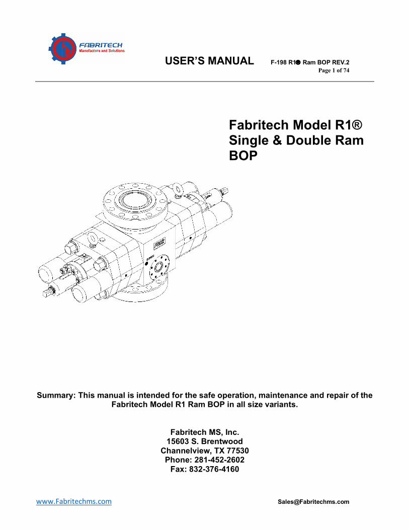
Fabritech Model R1® Single & Double Ram BOP
Summary: This manual is intended for the safe operation, maintenance and repair of the
Fabritech Model R1 Ram BOP in all size variants.
Fabritech MS, Inc. 15603 S. Brentwood
Channelview, TX 77530 Phone: 281-452-2602
Fax: 832-376-4160
USER’S MANUAL F-198 R1â Ram BOP REV.2 Page 2 of 74
www.Fabritechms.com [email protected]
REV. Description of Change: Date: Author: Approval: MOC#
1 Revised to include new data, more figures, tables, and part numbers. 3/28/20 J.S. J.G. N/A
2 Added part numbers and descriptions. 8/13/20 J.S. J.G. N/A
USER’S MANUAL F-198 R1â Ram BOP REV.2 Page 3 of 74
www.Fabritechms.com [email protected]
Section A: General Info…………………………………………………………………Pg.6 Usage Agreement Info, Cautions, & Warnings Depictions Safety Requirements Training of Personnel Recommendation of Tools General Safety Practices Replacing Components Maintenance at Intervals Proper Use of Equipment Section B: Introduction…………………………………………………………………Pg.9 Features Safety Precautions Section C: Installation & Operation………………………..…………………………Pg.13 Preliminary Inspection MODEL R1® RAM BOP Installation, Hook-up, and Preparation Bonnet Bolt Closure Lifting the Model R1 Ram BOP Hydraulic Connections Hydraulic Hookup Hydraulic System Model R1 Ram BOP Disassembly & Assembly Ram Block Assembly Ram Block Installation Operation and BOP Installation Procedure Ram Blocks Operational Characteristics Section D: Maintenance………………………………………..………………………Pg.51 Weekly Preventive Maintenance Monthly Preventive Maintenance Yearly Preventive Maintenance Three Year Preventive Maintenance Cleaning & Lubricating Recommendations Troubleshooting Storage of BOP Assembly Storage of Elastomers Section E: Spec. & Parts List…………………………………………………….……Pg.57 Dimensional Data Weights Volumetric Data Part Numbers
Table of Contents
USER’S MANUAL F-198 R1â Ram BOP REV.2 Page 4 of 74
www.Fabritechms.com [email protected]
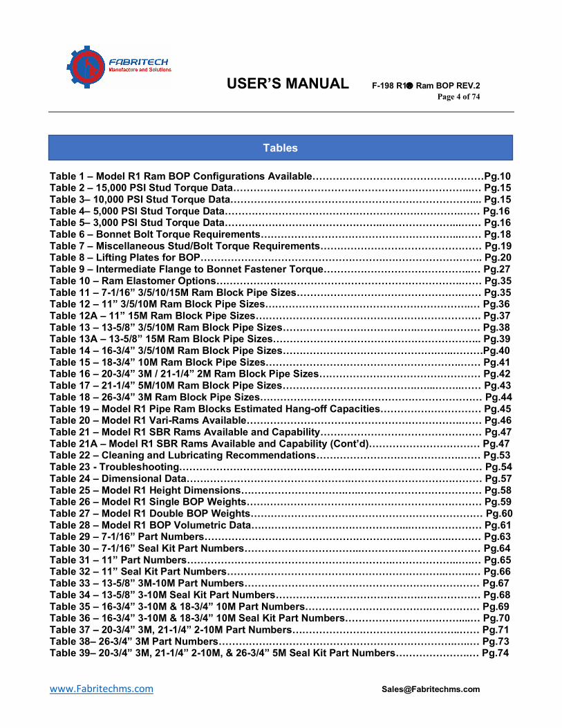
Table 1 – Model R1 Ram BOP Configurations Available……………………………………………Pg.10 Table 2 – 15,000 PSI Stud Torque Data……………………………………………………………..… Pg.15 Table 3– 10,000 PSI Stud Torque Data………………………………………………………………... Pg.15 Table 4– 5,000 PSI Stud Torque Data…………………………………………………………….…… Pg.16 Table 5– 3,000 PSI Stud Torque Data………………………………………..…………………...…… Pg.16 Table 6 – Bonnet Bolt Torque Requirements…………………………………………………...…… Pg.18 Table 7 – Miscellaneous Stud/Bolt Torque Requirements………………………………………… Pg.19 Table 8 – Lifting Plates for BOP……………………………………………….……………………….. Pg.20 Table 9 – Intermediate Flange to Bonnet Fastener Torque……………………………………..… Pg.27 Table 10 – Ram Elastomer Options……………………………………………………………….…… Pg.35 Table 11 – 7-1/16” 3/5/10/15M Ram Block Pipe Sizes………………………………………….…… Pg.35 Table 12 – 11” 3/5/10M Ram Block Pipe Sizes…………………………………………………….… Pg.36 Table 12A – 11” 15M Ram Block Pipe Sizes…………………………………………………………. Pg.37 Table 13 – 13-5/8” 3/5/10M Ram Block Pipe Sizes………………………………….……….……… Pg.38 Table 13A – 13-5/8” 15M Ram Block Pipe Sizes…………………………………………………….. Pg.39 Table 14 – 16-3/4” 3/5/10M Ram Block Pipe Sizes……………………………………….…..………Pg.40 Table 15 – 18-3/4” 10M Ram Block Pipe Sizes………………………………………………….…… Pg.41 Table 16 – 20-3/4” 3M / 21-1/4” 2M Ram Block Pipe Sizes………………………………………… Pg.42 Table 17 – 21-1/4” 5M/10M Ram Block Pipe Sizes………………………………….…...……..…… Pg.43 Table 18 – 26-3/4” 3M Ram Block Pipe Sizes………………………………………………………… Pg.44 Table 19 – Model R1 Pipe Ram Blocks Estimated Hang-off Capacities………………………… Pg.45 Table 20 – Model R1 Vari-Rams Available……………………………………………………….…… Pg.46 Table 21 – Model R1 SBR Rams Available and Capability………………………………………… Pg.47 Table 21A – Model R1 SBR Rams Available and Capability (Cont’d)…………………………… Pg.47 Table 22 – Cleaning and Lubricating Recommendations…………………………………….…… Pg.53 Table 23 - Troubleshooting……………………………………………………………………………… Pg.54 Table 24 – Dimensional Data………………………………………….………………………………… Pg.57 Table 25 – Model R1 Height Dimensions………………………….…..……………………………… Pg.58 Table 26 – Model R1 Single BOP Weights……………………………….…………………………… Pg.59 Table 27 – Model R1 Double BOP Weights…………………………………………………………… Pg.60 Table 28 – Model R1 BOP Volumetric Data………………………………………...………………… Pg.61 Table 29 – 7-1/16” Part Numbers…………………………………………………..……….…..……… Pg.63 Table 30 – 7-1/16” Seal Kit Part Numbers……………………………..…………..….……………… Pg.64 Table 31 – 11” Part Numbers…………………………………………………….………………..….… Pg.65 Table 32 – 11” Seal Kit Part Numbers………………………………………………………..……..… Pg.66 Table 33 – 13-5/8” 3M-10M Part Numbers……………………………………………….…………… Pg.67 Table 34 – 13-5/8” 3-10M Seal Kit Part Numbers…………………………………….……………… Pg.68 Table 35 – 16-3/4” 3-10M & 18-3/4” 10M Part Numbers……………………………….…………… Pg.69 Table 36 – 16-3/4” 3-10M & 18-3/4” 10M Seal Kit Part Numbers…………………….………....… Pg.70 Table 37 – 20-3/4” 3M, 21-1/4” 2-10M Part Numbers…………………………………………..…… Pg.71 Table 38– 26-3/4” 3M Part Numbers…………………………………………………………….…..… Pg.73 Table 39– 20-3/4” 3M, 21-1/4” 2-10M, & 26-3/4” 5M Seal Kit Part Numbers………………….… Pg.74
Tables
USER’S MANUAL F-198 R1â Ram BOP REV.2 Page 5 of 74
www.Fabritechms.com [email protected]
Figure 1 – Model R1 Ram Single Ram BOP…………………………………….………………….… Pg.9 Figure 2 - End Connection Examples…………………………………….…………………………… Pg.14 Figure 3 - Torque Pattern for API Connections……………………………………….,,……………… Pg.14 Figure 4 – Bonnet Torque Pattern…………………………………….………………….…,………… Pg.17 Figure 5 - MODEL R1® RAM BOP Hydraulic System Open Port………………….……………… Pg.21 Figure 6 - MODEL R1® RAM BOP Hydraulic System Close Port………………………………… Pg.22 Figure 7 – Typical Model R1 Pipe Ram…………………………………….…………………….…… Pg.34 Figure 8 – Typical Model R1 SBR Ram…………………………………….…………….…………… Pg.48 Figure 9 – Exploded View of Model R1 Ram BOP…………………………….…….……………… Pg.62
Figures
USER’S MANUAL F-198 R1â Ram BOP REV.2 Page 6 of 74
www.Fabritechms.com [email protected]
Section A: General Info Usage Agreement
This User’s Manual was designed to be used by personnel responsible for Installation, operation, and repair of the Model R1 Ram BOP. Fabritech Manufacture and Solutions, Inc. will not be held liable for errors in this literature, or from human error and/or misuse of equipment.
Info, Caution, & Warnings
Info, Caution, & Warnings are to be seen as points of specific action to be taken in
order to prevent and protect responsible personnel from potential injury or lethal conditions. They will also be informative to provide the reader/user of preventive actions concerning the equipment. Be aware of the following:
INFO:
The Info symbol above indicates that there is additional information concerning the specific
topic
CAUTION:
The caution symbol above indicates that there is a possibility of damage or injury to equipment
and or equipment. Extreme care shall be taken when performing these operations or procedures
WARNING:
The warning symbol above indicates a high risk of damage or danger to equipment and or
personnel. Failure to follow safe work procedures could result in serious fatal injury to personnel, as well as equipment damage.
USER’S MANUAL F-198 R1â Ram BOP REV.2 Page 7 of 74
www.Fabritechms.com [email protected]
Depictions
Figures and graphical illustrations are provided throughout this manual as an aid for identifying parts and becoming familiar with the different components. The depictions are solely for reference and are not to be considered to scale.
Safety Requirements
Proper maintenance is important for safe and reliable operation. All procedures, notes, and precautionary advice are recommended for optimal performance.
Take precaution by observing the safety requirements set forth in this section, as well as procedures Training of Personnel
All personnel responsible for operation, installation, repair, and or maintenance should be trained on rig safety, tool operation, and maintenance to ensure their safety.
Personnel involved with this equipment in any manner shall wear protective gear Recommendation of Tools
Some service operations may require the use of specific tools and it is recommended to only be used as stated. Personnel safety should be the priority.
General Safety Practices
The equipment may require or contain utilities such as electrical, hydraulic, pneumatic, or water cooling.
Read and follow guidelines below prior to installation or maintenance of equipment.
• Isolate energy sources prior to commencing work • Do not perform maintenance or repairs while operation • Wear protective gear throughout installation, maintenance, & repair
USER’S MANUAL F-198 R1â Ram BOP REV.2 Page 8 of 74
www.Fabritechms.com [email protected]
Replacing Components
• Verify all components are tagged and labeled during assembly/disassembly to ensure the components maintain traceability as well as correct installation.
• Replace failed or damaged components with original replacement parts. Failure to do so could result in equipment damage and or personnel.
Maintenance at Intervals Equipment must be maintained on a continual basis. Please refer to specific service manuals for recommendations.
Read and follow guidelines below prior to installation or maintenance of equipment.
Proper Use of Equipment This equipment is to be used ONLY for its intended and designed purpose.
USER’S MANUAL F-198 R1â Ram BOP REV.2 Page 9 of 74
www.Fabritechms.com [email protected]
Section B: Introduction
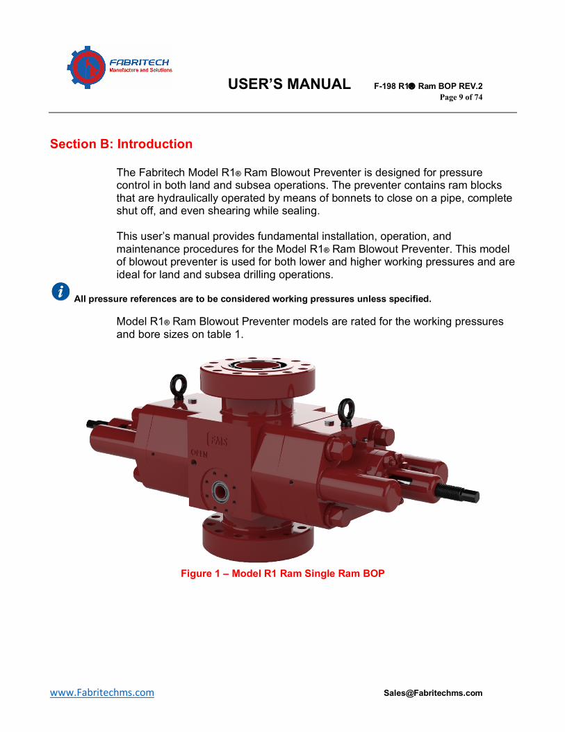
The Fabritech Model R1® Ram Blowout Preventer is designed for pressure control in both land and subsea operations. The preventer contains ram blocks that are hydraulically operated by means of bonnets to close on a pipe, complete shut off, and even shearing while sealing.
This user’s manual provides fundamental installation, operation, and
maintenance procedures for the Model R1® Ram Blowout Preventer. This model of blowout preventer is used for both lower and higher working pressures and are ideal for land and subsea drilling operations.
All pressure references are to be considered working pressures unless specified.
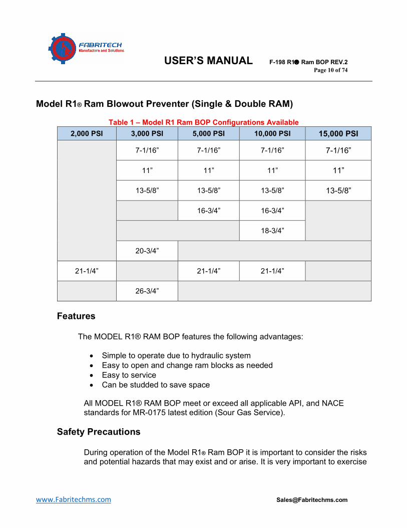
Model R1® Ram Blowout Preventer models are rated for the working pressures and bore sizes on table 1.
Figure 1 – Model R1 Ram Single Ram BOP
USER’S MANUAL F-198 R1â Ram BOP REV.2 Page 10 of 74
www.Fabritechms.com [email protected]
Model R1® Ram Blowout Preventer (Single & Double RAM)
Table 1 – Model R1 Ram BOP Configurations Available 2,000 PSI 3,000 PSI 5,000 PSI 10,000 PSI 15,000 PSI
7-1/16” 7-1/16” 7-1/16” 7-1/16”
11” 11” 11” 11”
13-5/8” 13-5/8” 13-5/8” 13-5/8”
16-3/4” 16-3/4”
18-3/4”
20-3/4”
21-1/4” 21-1/4” 21-1/4”
26-3/4”
Features
The MODEL R1® RAM BOP features the following advantages:
• Simple to operate due to hydraulic system • Easy to open and change ram blocks as needed • Easy to service • Can be studded to save space
All MODEL R1® RAM BOP meet or exceed all applicable API, and NACE standards for MR-0175 latest edition (Sour Gas Service).
Safety Precautions During operation of the Model R1® Ram BOP it is important to consider the risks and potential hazards that may exist and or arise. It is very important to exercise
USER’S MANUAL F-198 R1â Ram BOP REV.2 Page 11 of 74
www.Fabritechms.com [email protected]
and apply standard safety precautions in order to avoid or mitigate any potential injuries or fatalities that could result from error.
Pneumatic System Precautions The hydraulic systems that supply the Model R1® Ram BOP should be considered as potentially dangerous, and precautions should be taken.
• Control line that operates opening port • Supply correct pressures and volume to ensure correct function of
equipment • Use filters in air supply to prevent debris from entering the pneumatic
system • Avoid contact with air leaks or streams if occurring • Shut off and vent any pneumatic source prior to servicing
Hydraulic System Precautions
The hydraulic systems that supply the Model R1® Ram BOP should be considered as potentially dangerous, and precautions should be taken.
• Use recommended hydraulic fluid to ensure correct function of equipment
• Use filters for the hydraulic fluid to prevent debris from entering the hydraulic system
• Prior to operating the Model R1® Ram BOP, ensure that pressure relief valves are in working condition, and set to designated pressures
• Avoid contact with pressure or hydraulic fluid leaks if occurring • Shut off and vent any electrical and pneumatic sources prior to
servicing. • Use only Nitrogen Gas when pre-charging accumulators in order to
prevent failure or explosion. Cables & Hoses Precautions
All cables and hoses should be taken care of in order to prevent injury and or damage to equipment.
• Ensure all cables and hoses are protected from cutting, scraping, pinching, and other physical damage
• Make sure to consider routing cables and hoses outside and away from mechanical equipment
USER’S MANUAL F-198 R1â Ram BOP REV.2 Page 12 of 74
www.Fabritechms.com [email protected]
• Make sure to comply with all recommended bend radius for cable and hose manufacturers
Welding & Cutting Precautions
• Avoid welding or using acetylene cutting torches near unprotected
cables or hoses • Use precaution to prevent weld slag or spatter from entering the
hydraulic system
Work Area Safety & Precautions • Avoid and or remove any hazardous or flammable materials as
quickly as possible from the work area in order to prevent any injury to personnel
Flammable materials may also include kerosene, gasoline, oxygen tanks, acetylene tanks or any combustible gas.
Compatible Replacement Parts
It is important to use only parts manufactured from Fabritech, in order to maintain proper compatibility, usability, as well as to ensure safe equipment operation. See the end of this document for part numbers. Contact an FMS representative for replacement parts.
USER’S MANUAL F-198 R1â Ram BOP REV.2 Page 13 of 74
www.Fabritechms.com [email protected]
Section C: Installation & Operation
Preliminary Inspection
Prior to installation and or each new well, perform the following preliminary inspections as a preventive measure
1. Clean the Model R1® Ram BOP per recommendations outlined in this document.
2. Inspect the MODEL R1® RAM BOP components for physical damage and or abnormal wear.
3. Perform a visual inspection on the thru bore for abnormal wear. Check ram blocks for abnormal wear and replace as needed. Ensure the bore is no larger than 1/8” oversize at any point around the bore
Following the above preliminary inspection steps can help reduce upcoming installation time due to unexpected errors.
Prior to Installation
The procedures outlined in this document are indispensable in regards to installing MODEL R1® RAM BOP to flanged, studded connections. Refer to table(s) 2,3,4, and 5 for proper torqueing of API studs.
Torque data is reflected from API 5A2 recommended lubricant which should be applied to threads and nut face.
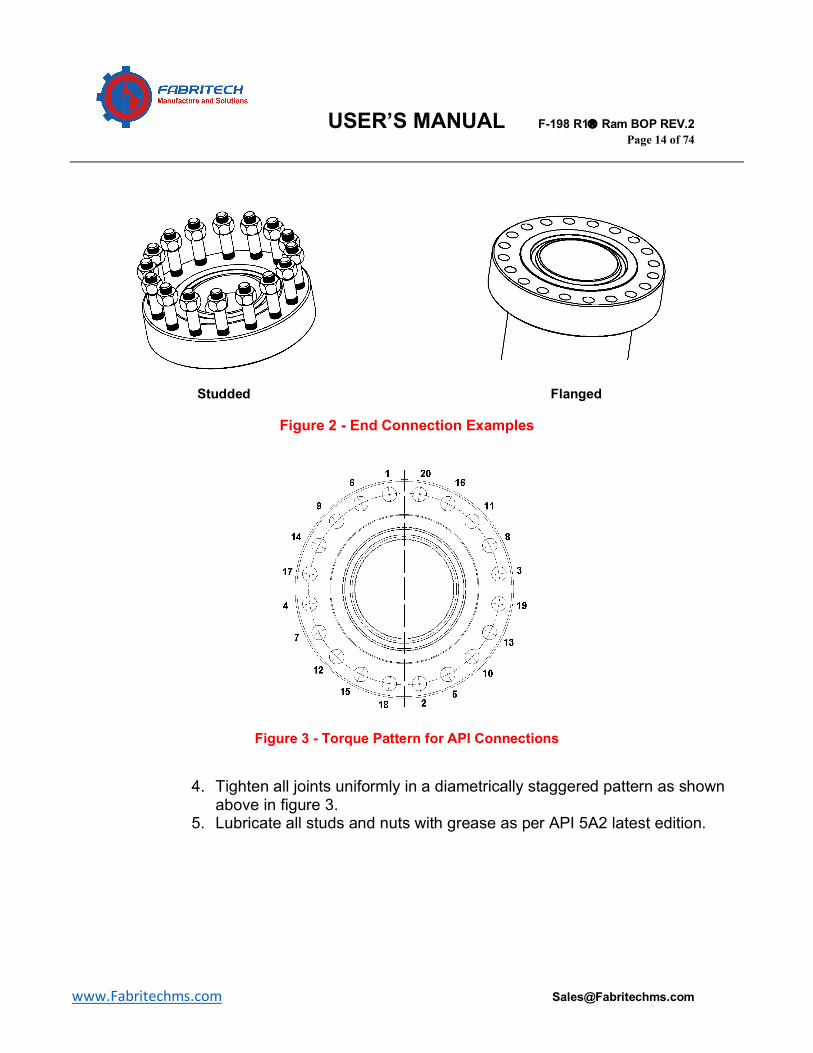
Flanged & Studded Connections Please refer to figures 2 and 3.
1. Install ring gasket 2. Install the MODEL R1® RAM BOP on mating flange 3. Install studs and or nuts
Follow extreme caution and care when removing and installing tap end studs. Inspect threads and stud holes for damage. Do not over torque studs when installing. Use specified lubricants.
USER’S MANUAL F-198 R1â Ram BOP REV.2 Page 14 of 74
www.Fabritechms.com [email protected]
Studded Flanged
Figure 2 - End Connection Examples
Figure 3 - Torque Pattern for API Connections
4. Tighten all joints uniformly in a diametrically staggered pattern as shown
above in figure 3. 5. Lubricate all studs and nuts with grease as per API 5A2 latest edition.
USER’S MANUAL F-198 R1â Ram BOP REV.2 Page 15 of 74
www.Fabritechms.com [email protected]
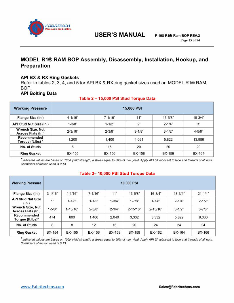
MODEL R1® RAM BOP Assembly, Disassembly, Installation, Hookup, and Preparation API BX & RX Ring Gaskets Refer to tables 2, 3, 4, and 5 for API BX & RX ring gasket sizes used on MODEL R1® RAM BOP. API Bolting Data
Table 2 – 15,000 PSI Stud Torque Data
*Indicated values are based on 105K yield strength, a stress equal to 50% of min. yield. Apply API 5A lubricant to face and threads of all nuts. Coefficient of friction used is 0.13.
Table 3– 10,000 PSI Stud Torque Data
Working Pressure 10,000 PSI
Flange Size (In.) 3-1/16” 4-1/16” 7-1/16” 11” 13-5/8” 16-3/4” 18-3/4” 21-1/4” API Stud Nut Size
(In.) 1” 1-1/8” 1-1/2” 1-3/4” 1-7/8” 1-7/8” 2-1/4” 2-1/2”
Wrench Size, Nut Across Flats (In.) 1-5/8” 1-13/16” 2-3/8” 2-3/4” 2-15/16” 2-15/16” 3-1/2” 3-7/8”
Recommended Torque (ft.lbs)* 474 600 1,400 2,040 3,332 3,332 5,822 8,030
No. of Studs 8 8 12 16 20 24 24 24
Ring Gasket BX-154 BX-155 BX-156 BX-158 BX-159 BX-162 BX-164 BX-166
*Indicated values are based on 105K yield strength, a stress equal to 50% of min. yield. Apply API 5A lubricant to face and threads of all nuts. Coefficient of friction used is 0.13.
Working Pressure 15,000 PSI
Flange Size (In.) 4-1/16” 7-1/16” 11” 13-5/8” 18-3/4”
API Stud Nut Size (In.) 1-3/8” 1-1/2” 2” 2-1/4” 3” Wrench Size, Nut Across Flats (In.) 2-3/16” 2-3/8” 3-1/8” 3-1/2” 4-5/8”
Recommended Torque (ft.lbs) * 1,200 1,400 4,061 5,822 13,986
No. of Studs 8 16 20 20 20
Ring Gasket BX-155 BX-156 BX-158 BX-159 BX-164
USER’S MANUAL F-198 R1â Ram BOP REV.2 Page 16 of 74
www.Fabritechms.com [email protected]
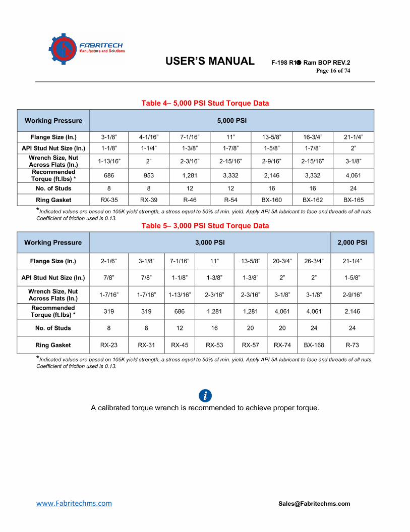
Table 4– 5,000 PSI Stud Torque Data
*Indicated values are based on 105K yield strength, a stress equal to 50% of min. yield. Apply API 5A lubricant to face and threads of all nuts. Coefficient of friction used is 0.13.
Table 5– 3,000 PSI Stud Torque Data
*Indicated values are based on 105K yield strength, a stress equal to 50% of min. yield. Apply API 5A lubricant to face and threads of all nuts. Coefficient of friction used is 0.13.
A calibrated torque wrench is recommended to achieve proper torque.
Working Pressure 5,000 PSI
Flange Size (In.) 3-1/8” 4-1/16” 7-1/16” 11” 13-5/8” 16-3/4” 21-1/4”
API Stud Nut Size (In.) 1-1/8” 1-1/4” 1-3/8” 1-7/8” 1-5/8” 1-7/8” 2” Wrench Size, Nut Across Flats (In.) 1-13/16” 2” 2-3/16” 2-15/16” 2-9/16” 2-15/16” 3-1/8”
Recommended Torque (ft.lbs) * 686 953 1,281 3,332 2,146 3,332 4,061
No. of Studs 8 8 12 12 16 16 24
Ring Gasket RX-35 RX-39 R-46 R-54 BX-160 BX-162 BX-165
Working Pressure 3,000 PSI 2,000 PSI
Flange Size (In.) 2-1/6” 3-1/8” 7-1/16” 11” 13-5/8” 20-3/4” 26-3/4” 21-1/4”
API Stud Nut Size (In.) 7/8” 7/8” 1-1/8” 1-3/8” 1-3/8” 2” 2” 1-5/8”
Wrench Size, Nut Across Flats (In.) 1-7/16” 1-7/16” 1-13/16” 2-3/16” 2-3/16” 3-1/8” 3-1/8” 2-9/16”
Recommended Torque (ft.lbs) * 319 319 686 1,281 1,281 4,061 4,061 2,146
No. of Studs 8 8 12 16 20 20 24 24
Ring Gasket RX-23 RX-31 RX-45 RX-53 RX-57 RX-74 BX-168 R-73
USER’S MANUAL F-198 R1â Ram BOP REV.2 Page 17 of 74
www.Fabritechms.com [email protected]
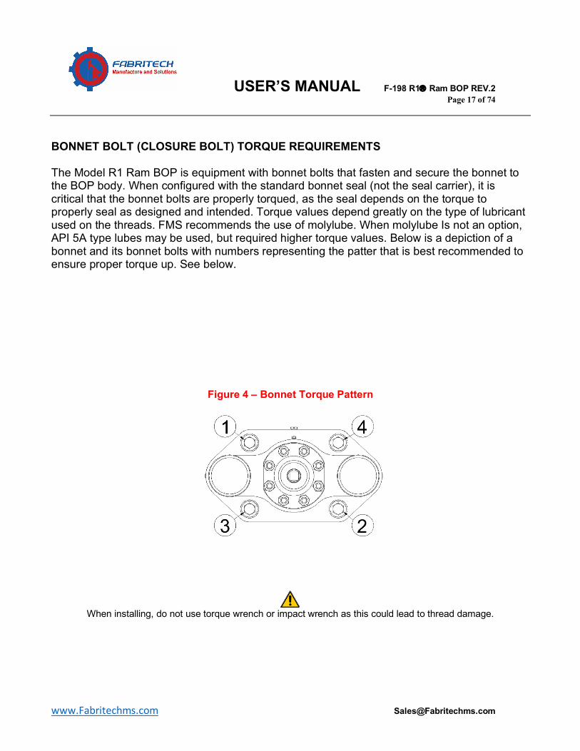
BONNET BOLT (CLOSURE BOLT) TORQUE REQUIREMENTS The Model R1 Ram BOP is equipment with bonnet bolts that fasten and secure the bonnet to the BOP body. When configured with the standard bonnet seal (not the seal carrier), it is critical that the bonnet bolts are properly torqued, as the seal depends on the torque to properly seal as designed and intended. Torque values depend greatly on the type of lubricant used on the threads. FMS recommends the use of molylube. When molylube Is not an option, API 5A type lubes may be used, but required higher torque values. Below is a depiction of a bonnet and its bonnet bolts with numbers representing the patter that is best recommended to ensure proper torque up. See below.
Figure 4 – Bonnet Torque Pattern
When installing, do not use torque wrench or impact wrench as this could lead to thread damage.
USER’S MANUAL F-198 R1â Ram BOP REV.2 Page 18 of 74
www.Fabritechms.com [email protected]
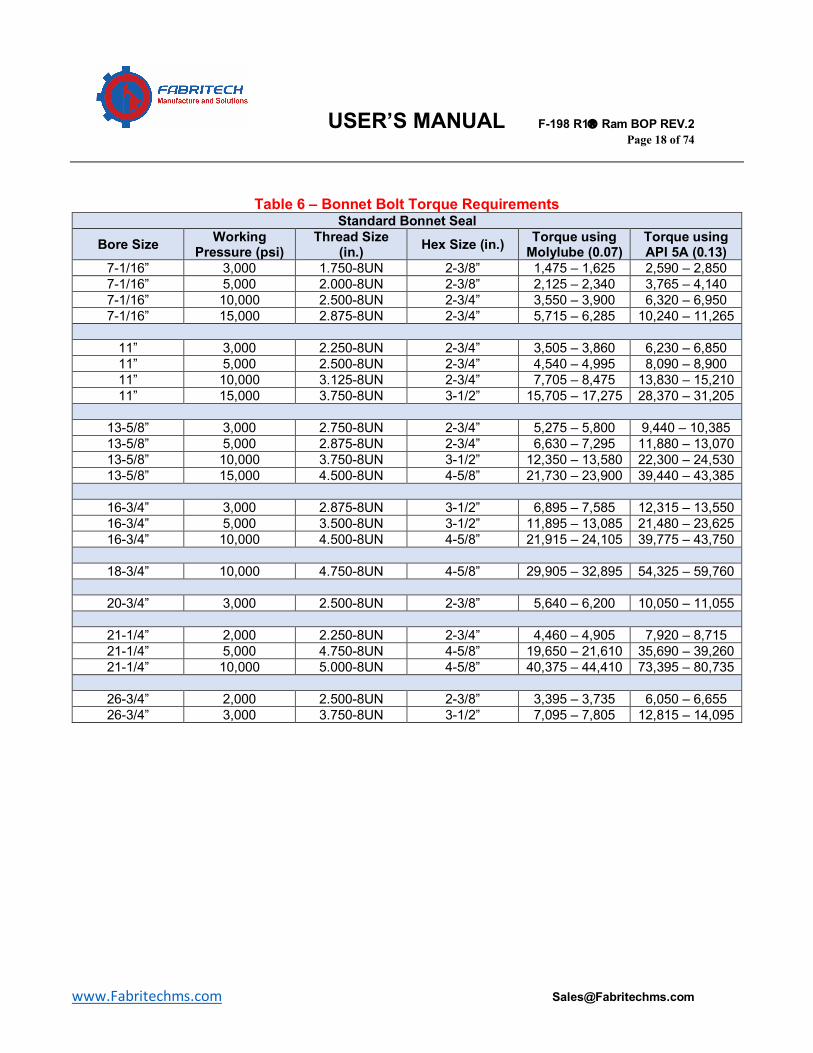
Table 6 – Bonnet Bolt Torque Requirements Standard Bonnet Seal
Bore Size Working Pressure (psi)
Thread Size (in.) Hex Size (in.) Torque using
Molylube (0.07) Torque using API 5A (0.13)
7-1/16” 3,000 1.750-8UN 2-3/8” 1,475 – 1,625 2,590 – 2,850 7-1/16” 5,000 2.000-8UN 2-3/8” 2,125 – 2,340 3,765 – 4,140 7-1/16” 10,000 2.500-8UN 2-3/4” 3,550 – 3,900 6,320 – 6,950 7-1/16” 15,000 2.875-8UN 2-3/4” 5,715 – 6,285 10,240 – 11,265
11” 3,000 2.250-8UN 2-3/4” 3,505 – 3,860 6,230 – 6,850 11” 5,000 2.500-8UN 2-3/4” 4,540 – 4,995 8,090 – 8,900 11” 10,000 3.125-8UN 2-3/4” 7,705 – 8,475 13,830 – 15,210 11” 15,000 3.750-8UN 3-1/2” 15,705 – 17,275 28,370 – 31,205
13-5/8” 3,000 2.750-8UN 2-3/4” 5,275 – 5,800 9,440 – 10,385 13-5/8” 5,000 2.875-8UN 2-3/4” 6,630 – 7,295 11,880 – 13,070 13-5/8” 10,000 3.750-8UN 3-1/2” 12,350 – 13,580 22,300 – 24,530 13-5/8” 15,000 4.500-8UN 4-5/8” 21,730 – 23,900 39,440 – 43,385
16-3/4” 3,000 2.875-8UN 3-1/2” 6,895 – 7,585 12,315 – 13,550 16-3/4” 5,000 3.500-8UN 3-1/2” 11,895 – 13,085 21,480 – 23,625 16-3/4” 10,000 4.500-8UN 4-5/8” 21,915 – 24,105 39,775 – 43,750
18-3/4” 10,000 4.750-8UN 4-5/8” 29,905 – 32,895 54,325 – 59,760
20-3/4” 3,000 2.500-8UN 2-3/8” 5,640 – 6,200 10,050 – 11,055
21-1/4” 2,000 2.250-8UN 2-3/4” 4,460 – 4,905 7,920 – 8,715 21-1/4” 5,000 4.750-8UN 4-5/8” 19,650 – 21,610 35,690 – 39,260 21-1/4” 10,000 5.000-8UN 4-5/8” 40,375 – 44,410 73,395 – 80,735
26-3/4” 2,000 2.500-8UN 2-3/8” 3,395 – 3,735 6,050 – 6,655 26-3/4” 3,000 3.750-8UN 3-1/2” 7,095 – 7,805 12,815 – 14,095
USER’S MANUAL F-198 R1â Ram BOP REV.2 Page 19 of 74
www.Fabritechms.com [email protected]
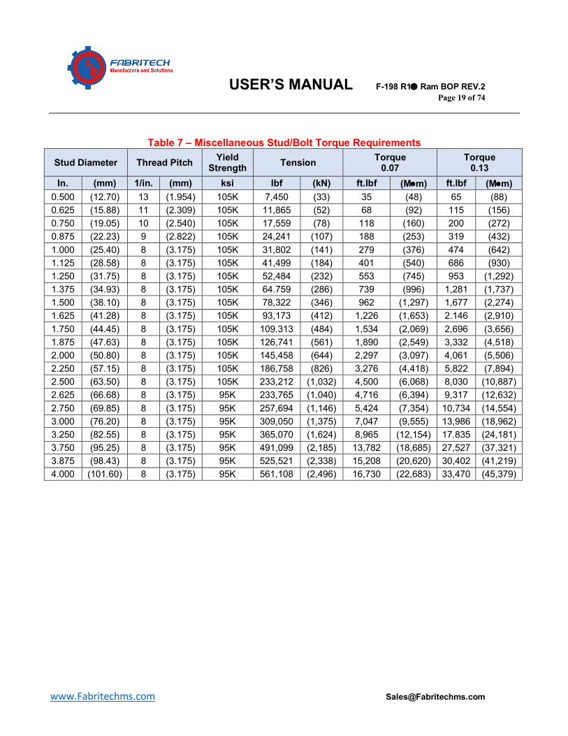
Table 7 – Miscellaneous Stud/Bolt Torque Requirements
Stud Diameter Thread Pitch Yield Strength Tension Torque
0.07 Torque
0.13 In. (mm) 1/in. (mm) ksi lbf (kN) ft.lbf (M•m) ft.lbf (M•m)
0.500 (12.70) 13 (1.954) 105K 7,450 (33) 35 (48) 65 (88) 0.625 (15.88) 11 (2.309) 105K 11,865 (52) 68 (92) 115 (156) 0.750 (19.05) 10 (2.540) 105K 17,559 (78) 118 (160) 200 (272) 0.875 (22.23) 9 (2.822) 105K 24,241 (107) 188 (253) 319 (432) 1.000 (25.40) 8 (3.175) 105K 31,802 (141) 279 (376) 474 (642) 1.125 (28.58) 8 (3.175) 105K 41,499 (184) 401 (540) 686 (930) 1.250 (31.75) 8 (3.175) 105K 52,484 (232) 553 (745) 953 (1,292) 1.375 (34.93) 8 (3.175) 105K 64.759 (286) 739 (996) 1,281 (1,737) 1.500 (38.10) 8 (3.175) 105K 78,322 (346) 962 (1,297) 1,677 (2,274) 1.625 (41.28) 8 (3.175) 105K 93,173 (412) 1,226 (1,653) 2.146 (2,910) 1.750 (44.45) 8 (3.175) 105K 109.313 (484) 1,534 (2,069) 2,696 (3,656) 1.875 (47.63) 8 (3.175) 105K 126,741 (561) 1,890 (2,549) 3,332 (4,518) 2.000 (50.80) 8 (3.175) 105K 145,458 (644) 2,297 (3,097) 4,061 (5,506) 2.250 (57.15) 8 (3.175) 105K 186,758 (826) 3,276 (4,418) 5,822 (7,894) 2.500 (63.50) 8 (3.175) 105K 233,212 (1,032) 4,500 (6,068) 8,030 (10,887) 2.625 (66.68) 8 (3.175) 95K 233,765 (1,040) 4,716 (6,394) 9,317 (12,632) 2.750 (69.85) 8 (3.175) 95K 257,694 (1,146) 5,424 (7,354) 10,734 (14,554) 3.000 (76.20) 8 (3.175) 95K 309,050 (1,375) 7,047 (9,555) 13,986 (18,962) 3.250 (82.55) 8 (3.175) 95K 365,070 (1,624) 8,965 (12,154) 17.835 (24,181) 3.750 (95.25) 8 (3.175) 95K 491,099 (2,185) 13,782 (18,685) 27,527 (37,321) 3.875 (98.43) 8 (3.175) 95K 525,521 (2,338) 15,208 (20,620) 30,402 (41,219) 4.000 (101.60) 8 (3.175) 95K 561,108 (2,496) 16,730 (22,683) 33,470 (45,379)
USER’S MANUAL F-198 R1â Ram BOP REV.2 Page 20 of 74
www.Fabritechms.com [email protected]
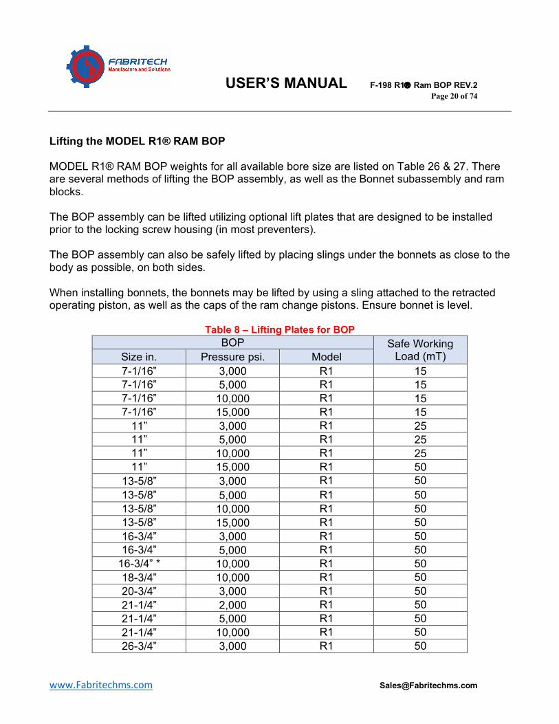
Lifting the MODEL R1® RAM BOP MODEL R1® RAM BOP weights for all available bore size are listed on Table 26 & 27. There are several methods of lifting the BOP assembly, as well as the Bonnet subassembly and ram blocks. The BOP assembly can be lifted utilizing optional lift plates that are designed to be installed prior to the locking screw housing (in most preventers). The BOP assembly can also be safely lifted by placing slings under the bonnets as close to the body as possible, on both sides. When installing bonnets, the bonnets may be lifted by using a sling attached to the retracted operating piston, as well as the caps of the ram change pistons. Ensure bonnet is level.
Table 8 – Lifting Plates for BOP BOP Safe Working
Load (mT) Size in. Pressure psi. Model 7-1/16” 3,000 R1 15 7-1/16” 5,000 R1 15 7-1/16” 10,000 R1 15 7-1/16” 15,000 R1 15
11” 3,000 R1 25 11” 5,000 R1 25 11” 10,000 R1 25 11” 15,000 R1 50
13-5/8” 3,000 R1 50 13-5/8” 5,000 R1 50 13-5/8” 10,000 R1 50 13-5/8” 15,000 R1 50 16-3/4” 3,000 R1 50 16-3/4” 5,000 R1 50
16-3/4” * 10,000 R1 50 18-3/4” 10,000 R1 50 20-3/4” 3,000 R1 50 21-1/4” 2,000 R1 50 21-1/4” 5,000 R1 50 21-1/4” 10,000 R1 50 26-3/4” 3,000 R1 50
USER’S MANUAL F-198 R1â Ram BOP REV.2 Page 21 of 74
www.Fabritechms.com [email protected]
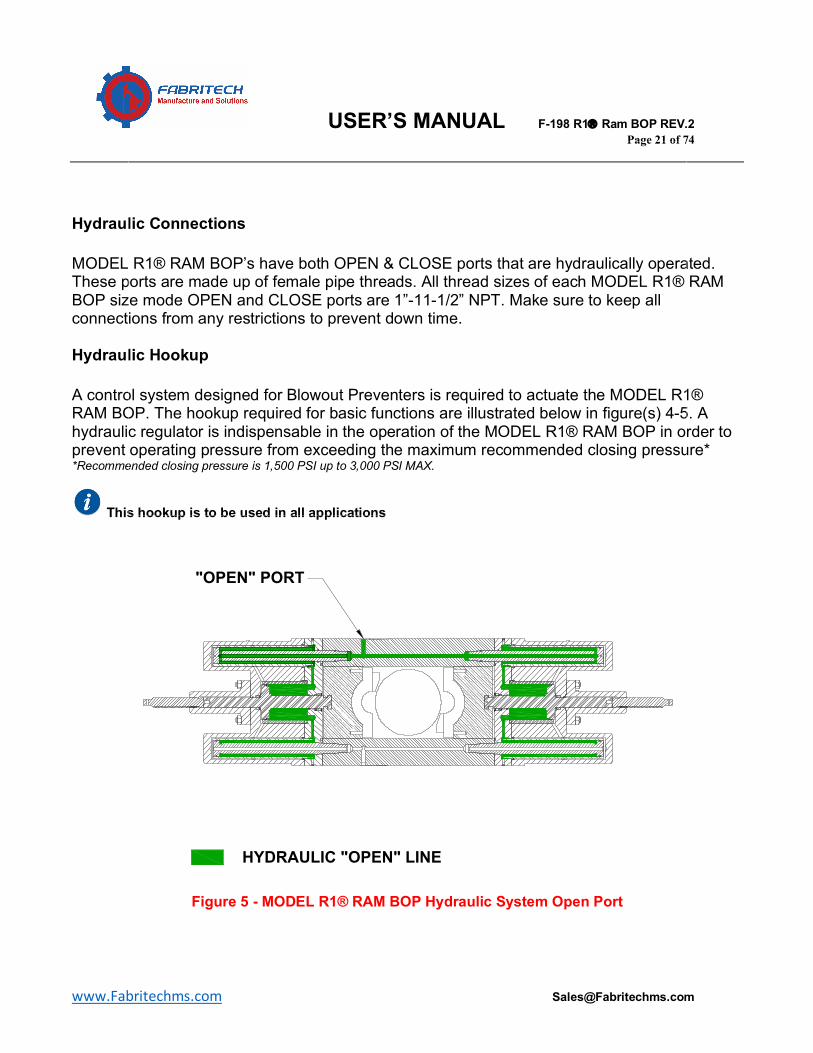
Hydraulic Connections MODEL R1® RAM BOP’s have both OPEN & CLOSE ports that are hydraulically operated. These ports are made up of female pipe threads. All thread sizes of each MODEL R1® RAM BOP size mode OPEN and CLOSE ports are 1”-11-1/2” NPT. Make sure to keep all connections from any restrictions to prevent down time. Hydraulic Hookup A control system designed for Blowout Preventers is required to actuate the MODEL R1® RAM BOP. The hookup required for basic functions are illustrated below in figure(s) 4-5. A hydraulic regulator is indispensable in the operation of the MODEL R1® RAM BOP in order to prevent operating pressure from exceeding the maximum recommended closing pressure* *Recommended closing pressure is 1,500 PSI up to 3,000 PSI MAX.
This hookup is to be used in all applications
Figure 5 - MODEL R1® RAM BOP Hydraulic System Open Port
4EKI���SJ����
*HQHUDO�2SHUDWLRQ�DQG�0DLQWHQDQFH�0DQXDO�
0RGHO�5��7\SH�8�%23
)RUP��������02'(/�5��7\SH�8�%23�2SHUDWLRQ��0DLQWHQDQFH�0DQXDO�5(9���-XO\�����
),*85(�����+<'5$8/,&�35(6685(�3$7+���5$06�&/26('��%211(76�23(1
),*85(�����+<'5$8/,&�35(6685(�3$7+���5$06�23(1��%211(76�&/26('
�23(1��3257
+<'5$8/,&��23(1��/,1(
+<'5$8/,&�&/26(�/,1(�&/26(��3257
USER’S MANUAL F-198 R1â Ram BOP REV.2 Page 22 of 74
www.Fabritechms.com [email protected]
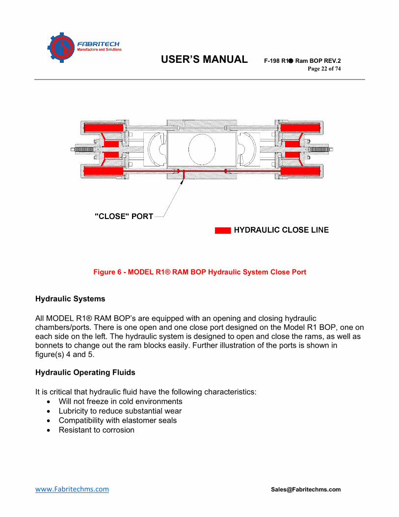
Figure 6 - MODEL R1® RAM BOP Hydraulic System Close Port Hydraulic Systems All MODEL R1® RAM BOP’s are equipped with an opening and closing hydraulic chambers/ports. There is one open and one close port designed on the Model R1 BOP, one on each side on the left. The hydraulic system is designed to open and close the rams, as well as bonnets to change out the ram blocks easily. Further illustration of the ports is shown in figure(s) 4 and 5. Hydraulic Operating Fluids It is critical that hydraulic fluid have the following characteristics:
• Will not freeze in cold environments • Lubricity to reduce substantial wear • Compatibility with elastomer seals • Resistant to corrosion
USER’S MANUAL F-198 R1â Ram BOP REV.2 Page 23 of 74
www.Fabritechms.com [email protected]
Recommended Hydraulic Fluids The following hydraulic fluids are listed in order of preference:
• Hydraulic oil with viscosity between 200-300 SSU at 100°F • Water with water soluble oil • Ready Mix BOP fluid
Emergency Fluid Recommendations The following fluids can be used as a substitute in emergency situations:
• If originally using hydraulic oil o Add SAE 10W or heavier motor oil o Use water if motor oil not readily available. Flush hydraulic system afterwards
• If originally using water/water soluble oil mixture, then add more water. Replace original mixture after emergency
Diesel, kerosene, and other flammable fluids cause elastomers to swell and deteriorate.
USER’S MANUAL F-198 R1â Ram BOP REV.2 Page 24 of 74
www.Fabritechms.com [email protected]
MODEL R1® RAM BOP DISSASSEMBLY & ASSEMBLY RECOMMENDED DISSASSEMBLY PROCEDURE
Prior to beginning, ensure all handling equipment is properly functioning, personal protective gear is being utilized, and all personnel are properly trained to these procedures prior to handling BOP’s. Failure to follow procedure and safety protocol may lead to injury and or death. Ensure all equipment has no wellbore pressure prior to opening. BOP DISSASSEMBLY
1. Ensure the rams are in the completely open position prior to disassembly. 2. Using a hydraulic torque wrench (recommended), break and unscrew all bonnet
bolts on both sides of the BOP Bonnets from the body. If a hydraulic torque wrench is not available, an impact wrench may be used but may cause damage.
3. Apply approximately 500 psi to the hydraulic close port to open the bonnets. (slight delay from one bonnet to the other is completely normal)
4. Install a lifting eye to the top of each ram block, and lift to remove from the operating piston rod using a hoist.
5. Remove seal carrier or bonnet seal from seal bore or intermediate flange respectively.
6. Using a hydraulic torque wrench or spanner wrench and hammer, break and unscrew locking screw housing nuts, and remove locking screw housing assembly or wedge lock assembly.
a. Manual lock screw housing assembly can be disassembled by removing the lock screw from the lock screw housing.
7. Remove locking screw housing assembly studs from bonnet using a small pipe wrench. (avoid gripping threads)
8. Remove bleeder gland and plug from the intermediate flange, as well as the NPT plug and plastic packing.
9. Unscrew plastic packing check valve. 10. Remove the O-ring from each bonnet bolt, and remove the bonnet bolts from
each bonnet. 11. Install lifting eyes to the top of each bonnet and attach a sling or cables to hoist. 12. Apply slight tension to the sling or cables in order to hold up the bonnet and
avoid bending due to hanging weight. 13. Using a crescent wrench, loosen the ram change pistons on the flats provided
close to the connection to the body. 14. Once the ram change pistons have come loose, move the bonnet assembly
away from the body in anticipation of disassembling the bonnet assembly.
USER’S MANUAL F-198 R1â Ram BOP REV.2 Page 25 of 74
www.Fabritechms.com [email protected]
BONNET DISSASSEMBLY
1. Position each bonnet with the intermediate flange facing up, on pallets or on stands.
2. Remove the ram guide pins from the intermediate flanges. 3. Remove the cap screws from the intermediate flanges and remove the
intermediate flanges from the bonnets. 4. Remove the ram change pistons from the ram change cylinders, and remove the
O-rings and wear rings. 5. Remove the operating pistons from the bonnets, and remove the operating
piston seal rings and wear rings from the operating pistons. 6. Remove the ram change cylinder O-rings from the cylinders, and remove the
cylinders from the bonnets. 7. Remove the operating cylinder O-rings from the operating cylinder, and remove
the cylinder from the bonnet. (These are for standard bonnets only) 8. Remove the remainder of the seals from the bonnet bore including wiper O-ring
and lip seal. 9. Remove the following from the intermediate flange: retaining ring, lip seal
retainer, connecting rod lip seal, backup ring, energizing ring, plastic packing ring, operating piston rod O-ring, and if applicable the wear pad.
TANDEM BOOSTER DISSASSEMBLY
1. After removing locking screw housing and locking screw, remove the bleeder gland and bleeder plug from on top of the cylinder head.
2. Remove any nuts, washers, studs and or screws, and disassemble the subassembly cylinder booster from the adapter plate.
3. Position the subassembly cylinder on stand with cylinder head facing down. 4. Break and remove cap screws and remove the adapter plate. 5. Loosen tail rod and stud. 6. Unscrew nuts, remove adapter plate, and O-ring. 7. Remove piston, leap seals, and wear ring. 8. Remove studs, and disassemble operating cylinder and O-ring. 9. Remove seal ring, and O-ring from cylinder head.
USER’S MANUAL F-198 R1â Ram BOP REV.2 Page 26 of 74
www.Fabritechms.com [email protected]
RECOMMENDED ASSEMBLY PROCEDURE BONNET ASSEMBLY
1. Position bonnet on assembly table or on pallet with the piston bore facing up. Install O-ring in the small diameter groove of the center bore in the bonnet. Install seal ring on the large diameter groove in the center bore in the bonnet with the lips of the seal ring facing up toward the interior of the bonnet.
2. Install O-rings in the two grooves on the exterior of the operating cylinder. Insert the operating cylinder with the small diameter first into the center bore of the bonnet. Applying small pressure, push until each one is seated. If necessary, use a rubber mallet to seat the cylinder in the bonnet.
3. Install O-rings on the ram change cylinders, and insert the cylinders into the bonnet, starting with the end opposite to the O-rings. Gently push until seated. If necessary, use a rubber mallet to seat the cylinder into the bonnet.
4. Install the O-rings or 4 lobe rings and wear bands on ram change piston heads. Insert the ram change pistons head first into the ram change cylinders ensuring the correct one is installed on each side (Open or Close).
5. The second bonnet assembly for the same ram bore cavity must have the open ram change piston on the opposite side.
6. Install the wear ring and lip seal on the operating piston, with the lip of the seal facing the connecting rod end. Insert the operating piston into the assembled bonnet and operating cylinder with the connecting rod end of the operating piston facing up.
7. Place the intermediate flange on the assembly table or pallet with the edge containing single tapped hole in the upright position and the oval groove facing towards the installation personnel.
8. Install O-rings or four lobe rings in ram change piston rod bores. Install wear ring in corresponding groove (only for 13-5/8” 15M, 16-3/4” 5/10M, 18-3/4” 10M, 21-1/4” 5M, and 26-3/4” 3M). Install O-ring in operating piston rod bore. Install plastic packing ring and energizing ring in operating piston rod bore.
9. Install connecting rod lip seal in the operating piston rod bore with lips facing away from the intermediate flange. Install lip seal retainer and retaining ring.
10. Using the two lifting holes located on the sides of the intermediate flanges, turn the intermediate flange over with the oval bonnet seal groove facing upwards. Using a sling, lift the intermediate flange and position it over the bonnet assembly. The plastic packing hole with the 1” NPT thread in the intermediate flange must be on the same side as the 1-1/8”-8UN threaded hole on the bonnet. Carefully lower the intermediate flange over the connecting rod end of the operating piston. Continue to lower the intermediate flange over the ram change
USER’S MANUAL F-198 R1â Ram BOP REV.2 Page 27 of 74
www.Fabritechms.com [email protected]
pistons. Ensure the operating cylinder and the ram change cylinders have started to enter their respective bores in the intermediate flange.
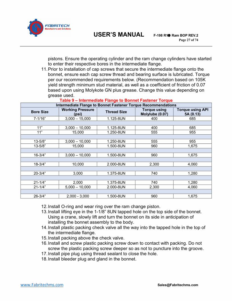
11. Prior to installation of cap screws that secure the intermediate flange onto the bonnet, ensure each cap screw thread and bearing surface is lubricated. Torque per our recommended requirements below. (Recommendation based on 105K yield strength minimum stud material, as well as a coefficient of friction of 0.07 based upon using Molykote GN plus grease. Change this value depending on grease used.
Table 9 – Intermediate Flange to Bonnet Fastener Torque Intermediate Flange to Bonnet Fastener Torque Recommendations
Bore Size Working Pressure (psi) Thread Size Torque using
Molylube (0.07) Torque using API
5A (0.13) 7-1/16” 3,000 – 15,000 1.125-8UN 400 685
11” 3,000 – 10,000 1.125-8UN 400 685 11” 15,000 1.250-8UN 555 955
13-5/8” 3,000 – 10,000 1.250-8UN 555 955 13-5/8” 15,000 1.500-8UN 960 1,675
16-3/4” 3,000 – 10,000 1.500-8UN 960 1,675
18-3/4” 10,000 2.000-8UN 2,300 4,060
20-3/4” 3,000 1.375-8UN 740 1,280
21-1/4” 2,000 1.375-8UN 740 1,280 21-1/4” 5,000 – 10,000 2.000-8UN 2,300 4,060
26-3/4” 2,000 - 3,000 1.500-8UN 960 1,675
12. Install O-ring and wear ring over the ram change piston. 13. Install lifting eye in the 1-1/8” 8UN tapped hole on the top side of the bonnet.
Using a crane, slowly lift and turn the bonnet on its side in anticipation of installing the bonnet assembly to the body.
14. Install plastic packing check valve all the way into the tapped hole in the top of the intermediate flange.
15. Install packing above the check valve. 16. Install and screw plastic packing screw down to contact with packing. Do not
screw the plastic packing screw deeper so as not to puncture into the groove. 17. Install pipe plug using thread sealant to close the hole. 18. Install bleeder plug and gland in the bonnet.
USER’S MANUAL F-198 R1â Ram BOP REV.2 Page 28 of 74
www.Fabritechms.com [email protected]
MANUAL LOCKING ASSEMBLY
1. Clean the lock screw and locking screw housing, and apply grease to the threads.
2. Thread the lock screw into the housing with the square end first, until the head of the screw bottoms in the inside of the housing.
TANDEM BOOSTER ASSEMBLY
1. Install lip seal and O-ring into bore of cylinder head and apply seal lubricant to the seal.
2. Install O-ring into cylinder and apply seal lubricant to the seal. 3. Install studs on cylinder head and torque to 100-200 ft-lb. 4. Install cylinder onto cylinder head. 5. Install seal ring and wear ring onto OD of piston. 6. Install seal ring and wear ring onto ID of piston. 7. Apply seal lubricant on seals and wear rings and insert piston onto tail rod and
into cylinder. Install stud on tail rod. 8. Install adapter spacer onto cylinder. Align eyes with studs. 9. Install nuts and torque to 100-200 ft.lb. 10. Install socket head cap screws on adapter. 11. Return the cylinder assembly booster. Coat the face with light oil and install onto
adapter. 12. Coat the threads of the studs or screws with thread lubricant. Install short thread
ends of studs into adapter. 13. Install studs or screws and torque per above table 9.
Tandem boosters are optional, and may be installed when deemed necessary for different pipe.
USER’S MANUAL F-198 R1â Ram BOP REV.2 Page 29 of 74
www.Fabritechms.com [email protected]
RECOMMENDED INSTALLATION PROCEDURE BONNET INSTALLATION
1. Install the ram guide pins into the intermediate flange. Tighten each pin using a small pipe wrench. When possible, torque per recommended values per table 9 below.
2. Insert the bonnet bolts through the bonnet and intermediate flange and slip the O-ring over bonnet bolt threads and onto the undercut area.
3. Connect hydraulic system to the open and close ram change pistons (1/2” NPT) and apply 500 psi to the close ram change piston to extend the ram change pistons.
4. Once the ram change pistons are fully extended, remove the pressure and disconnect the hoses from the pistons.
5. Using a rubber mallet, slightly hit both ram change piston ends to re-enter them by ½” in the bonnet. This process will prevent the piston head from rubbing against the bonnet.
6. Grease each piston thread in anticipation of installation to BOP body. 7. Lift the bonnet subassembly using operating piston (in the retracted position) and
bonnet caps (exterior of where the ram change pistons are housed). 8. Gently engage the threads of the ram change pistons into the BOP body preps. 9. Ensure the bonnet is centered, leveled, and stable. 10. Continue to engage the ram change pistons simultaneously with a wrench
utilizing the flats on the pistons, until the pistons bottom out against the body. BONNET CLOSING
1. Install hydraulic lines to BOP boy open and close ports. 2. Remove bleeder plugs from the top of the bonnets and apply 300-500 psi to both
open and close ports alternately to expel air from the hydraulic operating system. 3. After all air has been bled from the system, tighten the bleed plugs. 4. Lubricate the seal areas for the bonnet seal in both the body and the
intermediate flange. 5. Lubricate the seal with grease to stick the seal into the groove and install it in the
intermediate flange. 6. Once the bonnet seals are securely installed in their grooves, slowly close the
bonnet assembly with about 300-500 psi operating pressure applied to the open port.
7. Ensure closing operation is smooth, and that all seals remained intact as the bonnets fully close.
8. Increasing the pressure to 1,500 psi, maintain this pressure and tighten bonnet bolts per requirements on Table 6.
USER’S MANUAL F-198 R1â Ram BOP REV.2 Page 30 of 74
www.Fabritechms.com [email protected]
TANDEM BOOSTER INSTALLATION
1. If standard locking screw assembly is present, remove at this time. 2. Remove studs or screws and disassemble adapter plate from assembly cylinder
booster. 3. Coat face with light oil and install adapter using socket head cap screws on the
bonnet and apply torque per Table 9. 4. Remove tail rod from tandem booster cartridge, and screw tandem booster tail
rod into operating piston tail rod. Torque to approximately 100-200 ft.lbs. Ensure correct contact face of the rods.
5. Coat adapter and tail rod face with light oil. 6. Install tandem booster cartridge into adapter. 7. Install studs or screws and apply torque per Table 8. 8. Spray or apply anticorrosive oil directly inside open chamber. 9. Install muffler filter into adapter spacer (When and if applicable). 10. Install plumbing from end cap of bonnet to tandem booster.
MANUAL LOCKING SCREW INSTALLATION
1. Clean tail rod female thread and apply thread locker. 2. Install tap end studs into bonnet (short thread screws into bonnet) and tighten
with wrench. 3. Using a sling, lift the locking screw assembly to be in line with the tail rod of the
operating piston. 4. Position the assembly over the studs, and secure with nuts.
USER’S MANUAL F-198 R1â Ram BOP REV.2 Page 31 of 74
www.Fabritechms.com [email protected]
RAM BLOCK ASSEMBLY TOP SEAL AND PACKER INSTALLATION (BLIND, PIPE, AND VBR)
1. The Model R1 Blind, Pipe, and Variable Bore Ram blocks require a top seal and a packer.
2. Prior to installation of the packer, ensure the packer area on the ram block is free from damage. Lubricate the packer and the area where the packer will sit in the ram with light grease.
3. Install packer by pushing into the packer area of the ram block. 4. Prior to installation of top seal, ensure the top seal area is clean and free from
damage. 5. Lubricate the top seal and its mounting pins and the top seal groove on the ram
block using light oil grease. 6. Push the top seal into the groove, ensuring the pins intersect the pins of the
packer. If needed, use a soft hammer or mallet to pound the top seal into place.
SHEAR BLIND RAM ELASTOMER INSTALLATION
1. The shear blind rams (SBR’s) are slightly different than the typical blind, pipe, and VBR rams. SBR’s are comprised of one Upper ram and one Lower ram, each of which plays its role in the shear blade mating mechanism.
2. At the moment, FMS has designed several SBR’s that has characteristics particular to the end user.
a. Standard SBR’s b. SBR’s for H2S service c. Dual String SBR’s (ask for more information)
3. Top seals typically stay the same throughout different types of SBR’s, but the
blade seals and side packers change. 4. Model R1 SBR
a. Ensuring both upper and lower rams are clean and free from damage, lubricate side packers, blade packer, mounting pins, and all surfaces of the ram blocks that will be in contact with elastomers with light grease.
b. Install left and right-side packers in the upper ram, and ensure the correct side is installed, as they are not interchangeable.
c. Install the blade packer in the lower ram. Push the packer into the ram block recess in the face.
d. Lubricate top seal including pins, and seal groove. e. Push top seal into the groove, ensuring the pins are inserted properly. If
needed, use a soft hammer or mallet to pound the top seal into place.
USER’S MANUAL F-198 R1â Ram BOP REV.2 Page 32 of 74
www.Fabritechms.com [email protected]
RAM BLOCK INSTALLATION
1. With the bonnet assemblies installed on the BOP body, apply hydraulic pressure to the close port (approx. 300-500 psi) to open the bonnets and extend the operating rod toward the body.
2. Clean and inspect connecting rod and ram change piston shafts. Apply light oil. 3. Clean, inspect, and polish any burr or dents that may be present in the ram
cavity. 4. Apply grease to the cavity and the ram blocks 5. Lift the ram block with a lifting eye on the top of the ram, and position it to
engage the bottom slot of the ram to the end of the connecting rod. 6. Apply pressure on the close port (approx. 300-500 psi). 7. At this point, inspect and or change bonnet seal if necessary. 8. Clean, inspect, and chase any issues witnessed on bonnet bolts or bolt holes. 9. Apply grease to bonnet bolts and bolt holes. 10. Apply open pressure slowly, and ensure smooth operation of the ram and bonnet
closure. 11. After bonnet has been closed, apply constant pressure of 1,500 psi and tighten
all bonnet bolts per Table 6. OPERATION AND BOP INSTALLATION PROCEDURE PREPARATION
1. Before anticipation installation of BOP, ensure the following is met: a. Ensure all pressure ratings and capacities of accumulators and pressure
pumps meet or exceed regulatory requirements. b. Ensure all equipment has been tested and or maintained per STD 53
recommendations. c. Ensure all hydraulic and pneumatic connections at the site are free from
damage. d. Ensure proper torqueing equipment is available on site. e. Ensure all ring gaskets are available for all equipment.
USER’S MANUAL F-198 R1â Ram BOP REV.2 Page 33 of 74
www.Fabritechms.com [email protected]
INSTALLATION
1. Ensure the BOP is properly oriented. Typically, there will be an indicator on the BOP that helps orient the equipment.
2. Inspect the BOP, its ram blocks, and elastomers during the installation. 3. Remove any flange protectors at this time. 4. Install the BOP on a test stump. 5. Drain any fluid that is in the hydraulic system, as this fluid is for preservation
only. 6. Connect hydraulic lines to open and close ports, and flush with new clean fluid. 7. Test to ensure there are no leaks. (typically tested at 2,250 psi) 8. Install the rams intended for use in the operation. 9. During installation of rams at all times, it is imperative that the ram bore and
bonnet be inspected for any abnormal wear. Grind out any folded metal surfaces at the intersection of the bore and the ram cavity if possible.
10. At this point, the BOP is ready for service.

USER’S MANUAL F-198 R1â Ram BOP REV.2 Page 34 of 74
www.Fabritechms.com [email protected]
RAM BLOCKS Fabritech manufactures a variety of ram blocks that can be used during different drilling operations in the Model R1 Ram BOP. Nomenclature:
• Pipe Rams o Pipe rams are the standard rams that are designed with a specific bore. Pipe
rams are able to close on the designated pipe size only. • Blind Rams
o Blind rams are rams that are designed for complete shut off of the well. Blind rams are used when there is no pipe or casing in the well.
• VBR Rams o VBR rams are Variable Bore Rams that offer closure and seal on a range of pipe
sizes. VBR rams are used to avoid having to open the BOP to change out rams. • SBR Rams
o SBR rams are Shear Blind Rams that offer shear of pipe and complete shut off of the well.
Figure 7 – Typical Model R1 Pipe Ram
Above is a depiction of a Model R1 Pipe Ram block set without top seals or packers.
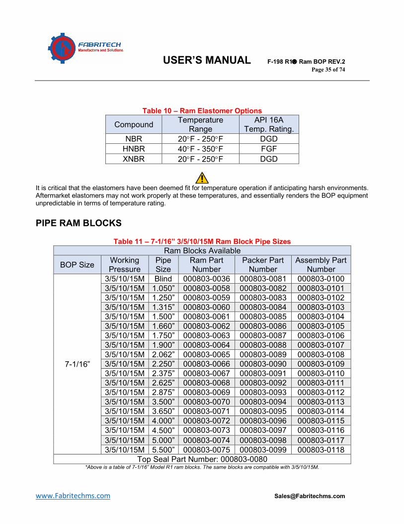
Technical Information: Model R1 ram blocks require top seals and a packers prior to installation in the preventer. Standard NBR top seals and packers are designed to operate between 20°F - 250°F. High temperature HNBR top seals and packers are available through special order that are designed to operate between 40°F - 350°F. See table below for reference.
USER’S MANUAL F-198 R1â Ram BOP REV.2 Page 35 of 74
www.Fabritechms.com [email protected]
Table 10 – Ram Elastomer Options
Compound Temperature Range
API 16A Temp. Rating.
NBR 20°F - 250°F DGD HNBR 40°F - 350°F FGF XNBR 20°F - 250°F DGD
It is critical that the elastomers have been deemed fit for temperature operation if anticipating harsh environments. Aftermarket elastomers may not work properly at these temperatures, and essentially renders the BOP equipment unpredictable in terms of temperature rating. PIPE RAM BLOCKS
Table 11 – 7-1/16” 3/5/10/15M Ram Block Pipe Sizes Ram Blocks Available
BOP Size Working Pressure
Pipe Size
Ram Part Number
Packer Part Number
Assembly Part Number
7-1/16”
3/5/10/15M Blind 000803-0036 000803-0081 000803-0100 3/5/10/15M 1.050” 000803-0058 000803-0082 000803-0101 3/5/10/15M 1.250” 000803-0059 000803-0083 000803-0102 3/5/10/15M 1.315” 000803-0060 000803-0084 000803-0103 3/5/10/15M 1.500” 000803-0061 000803-0085 000803-0104 3/5/10/15M 1.660” 000803-0062 000803-0086 000803-0105 3/5/10/15M 1.750” 000803-0063 000803-0087 000803-0106 3/5/10/15M 1.900” 000803-0064 000803-0088 000803-0107 3/5/10/15M 2.062” 000803-0065 000803-0089 000803-0108 3/5/10/15M 2.250” 000803-0066 000803-0090 000803-0109 3/5/10/15M 2.375” 000803-0067 000803-0091 000803-0110 3/5/10/15M 2.625” 000803-0068 000803-0092 000803-0111 3/5/10/15M 2.875” 000803-0069 000803-0093 000803-0112 3/5/10/15M 3.500” 000803-0070 000803-0094 000803-0113 3/5/10/15M 3.650” 000803-0071 000803-0095 000803-0114 3/5/10/15M 4.000” 000803-0072 000803-0096 000803-0115 3/5/10/15M 4.500” 000803-0073 000803-0097 000803-0116 3/5/10/15M 5.000” 000803-0074 000803-0098 000803-0117 3/5/10/15M 5.500” 000803-0075 000803-0099 000803-0118
Top Seal Part Number: 000803-0080 *Above is a table of 7-1/16” Model R1 ram blocks. The same blocks are compatible with 3/5/10/15M.
USER’S MANUAL F-198 R1â Ram BOP REV.2 Page 36 of 74
www.Fabritechms.com [email protected]
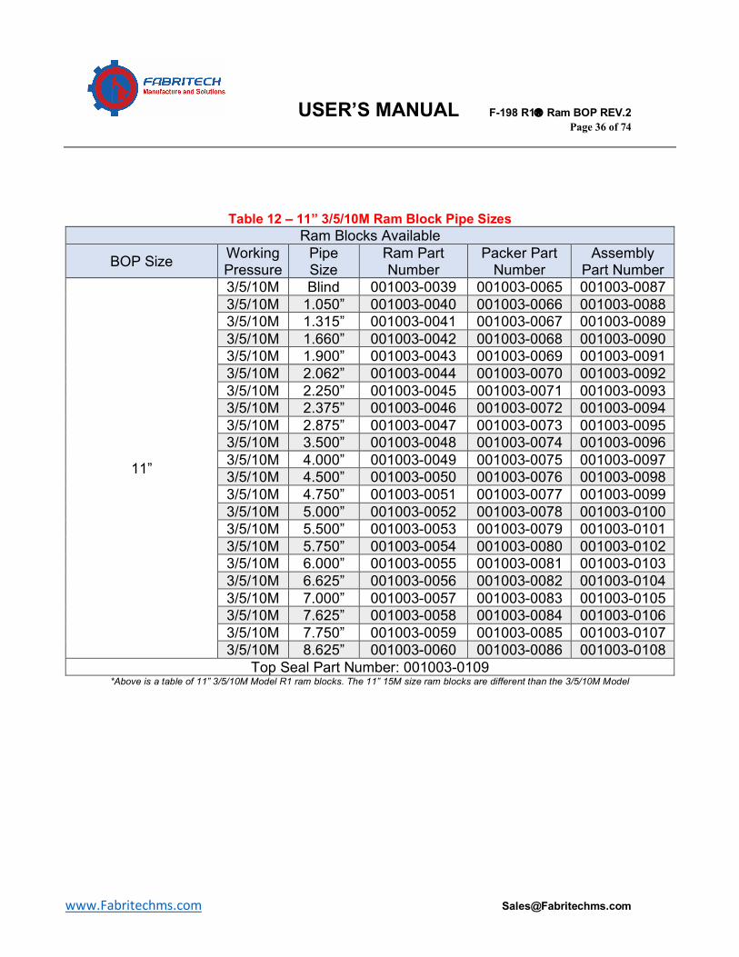
Table 12 – 11” 3/5/10M Ram Block Pipe Sizes Ram Blocks Available
BOP Size Working Pressure
Pipe Size
Ram Part Number
Packer Part Number
Assembly Part Number
11”
3/5/10M Blind 001003-0039 001003-0065 001003-0087 3/5/10M 1.050” 001003-0040 001003-0066 001003-0088 3/5/10M 1.315” 001003-0041 001003-0067 001003-0089 3/5/10M 1.660” 001003-0042 001003-0068 001003-0090 3/5/10M 1.900” 001003-0043 001003-0069 001003-0091 3/5/10M 2.062” 001003-0044 001003-0070 001003-0092 3/5/10M 2.250” 001003-0045 001003-0071 001003-0093 3/5/10M 2.375” 001003-0046 001003-0072 001003-0094 3/5/10M 2.875” 001003-0047 001003-0073 001003-0095 3/5/10M 3.500” 001003-0048 001003-0074 001003-0096 3/5/10M 4.000” 001003-0049 001003-0075 001003-0097 3/5/10M 4.500” 001003-0050 001003-0076 001003-0098 3/5/10M 4.750” 001003-0051 001003-0077 001003-0099 3/5/10M 5.000” 001003-0052 001003-0078 001003-0100 3/5/10M 5.500” 001003-0053 001003-0079 001003-0101 3/5/10M 5.750” 001003-0054 001003-0080 001003-0102 3/5/10M 6.000” 001003-0055 001003-0081 001003-0103 3/5/10M 6.625” 001003-0056 001003-0082 001003-0104 3/5/10M 7.000” 001003-0057 001003-0083 001003-0105 3/5/10M 7.625” 001003-0058 001003-0084 001003-0106 3/5/10M 7.750” 001003-0059 001003-0085 001003-0107 3/5/10M 8.625” 001003-0060 001003-0086 001003-0108
Top Seal Part Number: 001003-0109 *Above is a table of 11” 3/5/10M Model R1 ram blocks. The 11” 15M size ram blocks are different than the 3/5/10M Model
USER’S MANUAL F-198 R1â Ram BOP REV.2 Page 37 of 74
www.Fabritechms.com [email protected]
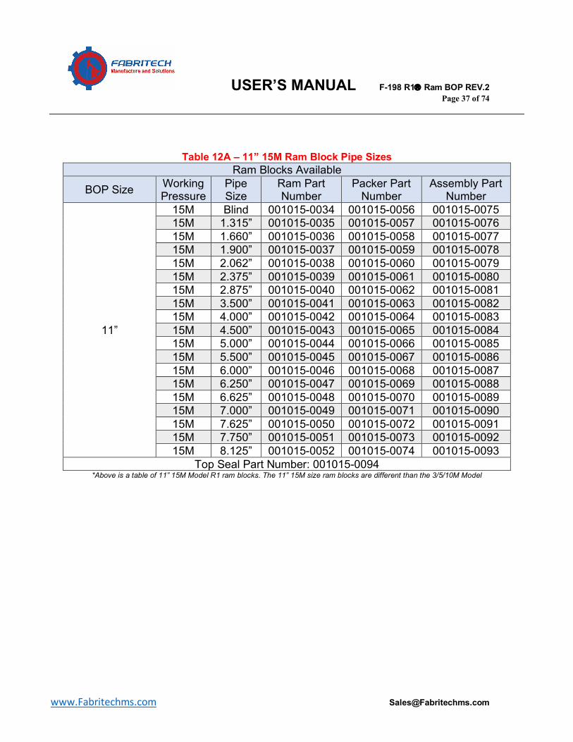
Table 12A – 11” 15M Ram Block Pipe Sizes
Ram Blocks Available
BOP Size Working Pressure
Pipe Size
Ram Part Number
Packer Part Number
Assembly Part Number
11”
15M Blind 001015-0034 001015-0056 001015-0075 15M 1.315” 001015-0035 001015-0057 001015-0076 15M 1.660” 001015-0036 001015-0058 001015-0077 15M 1.900” 001015-0037 001015-0059 001015-0078 15M 2.062” 001015-0038 001015-0060 001015-0079 15M 2.375” 001015-0039 001015-0061 001015-0080 15M 2.875” 001015-0040 001015-0062 001015-0081 15M 3.500” 001015-0041 001015-0063 001015-0082 15M 4.000” 001015-0042 001015-0064 001015-0083 15M 4.500” 001015-0043 001015-0065 001015-0084 15M 5.000” 001015-0044 001015-0066 001015-0085 15M 5.500” 001015-0045 001015-0067 001015-0086 15M 6.000” 001015-0046 001015-0068 001015-0087 15M 6.250” 001015-0047 001015-0069 001015-0088 15M 6.625” 001015-0048 001015-0070 001015-0089 15M 7.000” 001015-0049 001015-0071 001015-0090 15M 7.625” 001015-0050 001015-0072 001015-0091 15M 7.750” 001015-0051 001015-0073 001015-0092 15M 8.125” 001015-0052 001015-0074 001015-0093
Top Seal Part Number: 001015-0094 *Above is a table of 11” 15M Model R1 ram blocks. The 11” 15M size ram blocks are different than the 3/5/10M Model
USER’S MANUAL F-198 R1â Ram BOP REV.2 Page 38 of 74
www.Fabritechms.com [email protected]
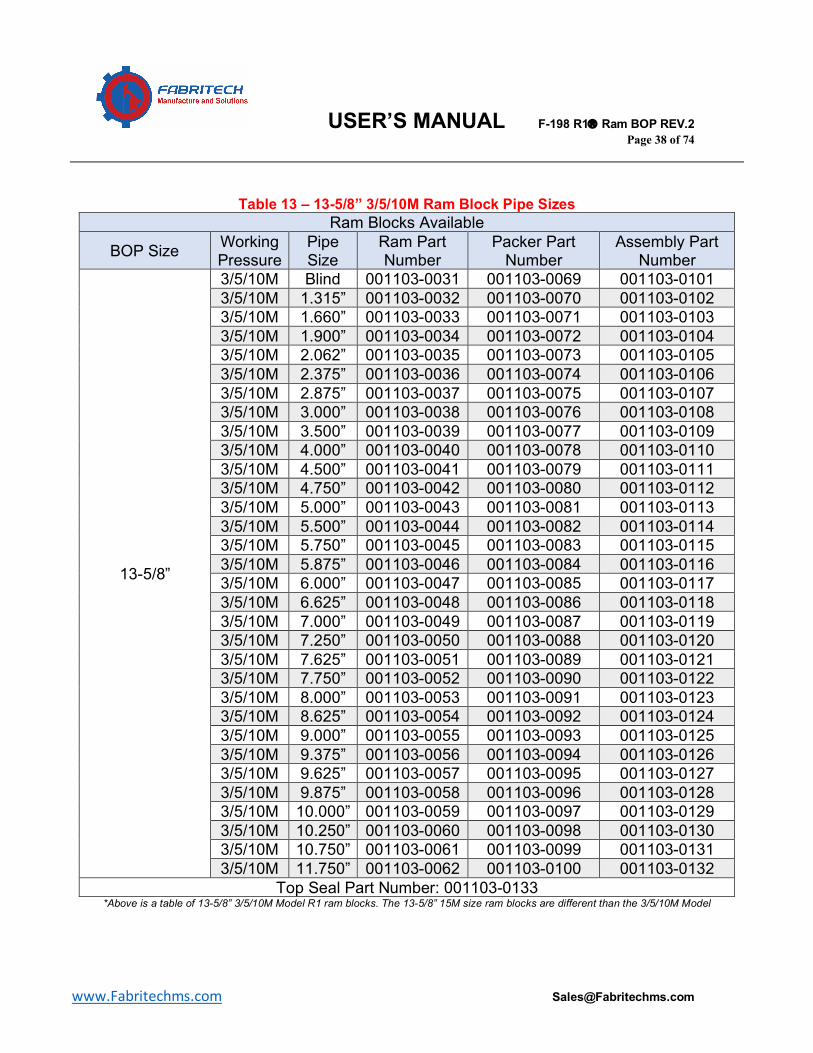
Table 13 – 13-5/8” 3/5/10M Ram Block Pipe Sizes Ram Blocks Available
BOP Size Working Pressure
Pipe Size
Ram Part Number
Packer Part Number
Assembly Part Number
13-5/8”
3/5/10M Blind 001103-0031 001103-0069 001103-0101 3/5/10M 1.315” 001103-0032 001103-0070 001103-0102 3/5/10M 1.660” 001103-0033 001103-0071 001103-0103 3/5/10M 1.900” 001103-0034 001103-0072 001103-0104 3/5/10M 2.062” 001103-0035 001103-0073 001103-0105 3/5/10M 2.375” 001103-0036 001103-0074 001103-0106 3/5/10M 2.875” 001103-0037 001103-0075 001103-0107 3/5/10M 3.000” 001103-0038 001103-0076 001103-0108 3/5/10M 3.500” 001103-0039 001103-0077 001103-0109 3/5/10M 4.000” 001103-0040 001103-0078 001103-0110 3/5/10M 4.500” 001103-0041 001103-0079 001103-0111 3/5/10M 4.750” 001103-0042 001103-0080 001103-0112 3/5/10M 5.000” 001103-0043 001103-0081 001103-0113 3/5/10M 5.500” 001103-0044 001103-0082 001103-0114 3/5/10M 5.750” 001103-0045 001103-0083 001103-0115 3/5/10M 5.875” 001103-0046 001103-0084 001103-0116 3/5/10M 6.000” 001103-0047 001103-0085 001103-0117 3/5/10M 6.625” 001103-0048 001103-0086 001103-0118 3/5/10M 7.000” 001103-0049 001103-0087 001103-0119 3/5/10M 7.250” 001103-0050 001103-0088 001103-0120 3/5/10M 7.625” 001103-0051 001103-0089 001103-0121 3/5/10M 7.750” 001103-0052 001103-0090 001103-0122 3/5/10M 8.000” 001103-0053 001103-0091 001103-0123 3/5/10M 8.625” 001103-0054 001103-0092 001103-0124 3/5/10M 9.000” 001103-0055 001103-0093 001103-0125 3/5/10M 9.375” 001103-0056 001103-0094 001103-0126 3/5/10M 9.625” 001103-0057 001103-0095 001103-0127 3/5/10M 9.875” 001103-0058 001103-0096 001103-0128 3/5/10M 10.000” 001103-0059 001103-0097 001103-0129 3/5/10M 10.250” 001103-0060 001103-0098 001103-0130 3/5/10M 10.750” 001103-0061 001103-0099 001103-0131 3/5/10M 11.750” 001103-0062 001103-0100 001103-0132
Top Seal Part Number: 001103-0133 *Above is a table of 13-5/8” 3/5/10M Model R1 ram blocks. The 13-5/8” 15M size ram blocks are different than the 3/5/10M Model
USER’S MANUAL F-198 R1â Ram BOP REV.2 Page 39 of 74
www.Fabritechms.com [email protected]
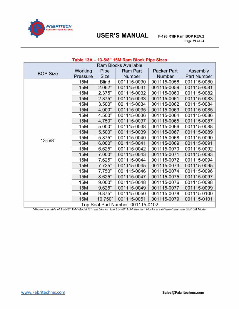
Table 13A – 13-5/8” 15M Ram Block Pipe Sizes Ram Blocks Available
BOP Size Working Pressure
Pipe Size
Ram Part Number
Packer Part Number
Assembly Part Number
13-5/8”
15M Blind 001115-0030 001115-0058 001115-0080 15M 2.062” 001115-0031 001115-0059 001115-0081 15M 2.375” 001115-0032 001115-0060 001115-0082 15M 2.875” 001115-0033 001115-0061 001115-0083 15M 3.500” 001115-0034 001115-0062 001115-0084 15M 4.000” 001115-0035 001115-0063 001115-0085 15M 4.500” 001115-0036 001115-0064 001115-0086 15M 4.750” 001115-0037 001115-0065 001115-0087 15M 5.000” 001115-0038 001115-0066 001115-0088 15M 5.500” 001115-0039 001115-0067 001115-0089 15M 5.875” 001115-0040 001115-0068 001115-0090 15M 6.000” 001115-0041 001115-0069 001115-0091 15M 6.625” 001115-0042 001115-0070 001115-0092 15M 7.000” 001115-0043 001115-0071 001115-0093 15M 7.625” 001115-0044 001115-0072 001115-0094 15M 7.725” 001115-0045 001115-0073 001115-0095 15M 7.750” 001115-0046 001115-0074 001115-0096 15M 8.625” 001115-0047 001115-0075 001115-0097 15M 9.000” 001115-0048 001115-0076 001115-0098 15M 9.625” 001115-0049 001115-0077 001115-0099 15M 9.875” 001115-0050 001115-0078 001115-0100 15M 10.750” 001115-0051 001115-0079 001115-0101 Top Seal Part Number: 001115-0102
*Above is a table of 13-5/8” 15M Model R1 ram blocks. The 13-5/8” 15M size ram blocks are different than the 3/5/10M Model
USER’S MANUAL F-198 R1â Ram BOP REV.2 Page 40 of 74
www.Fabritechms.com [email protected]
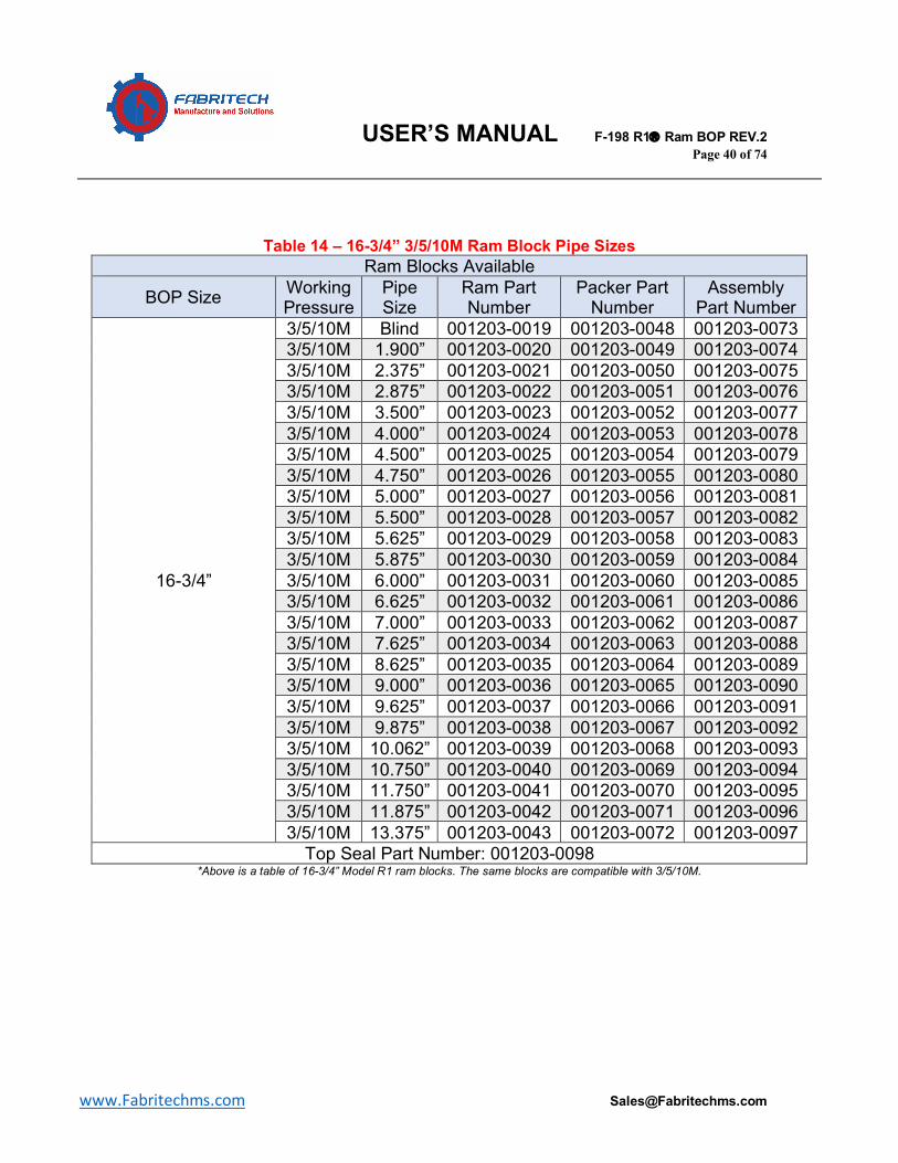
Table 14 – 16-3/4” 3/5/10M Ram Block Pipe Sizes
Ram Blocks Available
BOP Size Working Pressure
Pipe Size
Ram Part Number
Packer Part Number
Assembly Part Number
16-3/4”
3/5/10M Blind 001203-0019 001203-0048 001203-0073 3/5/10M 1.900” 001203-0020 001203-0049 001203-0074 3/5/10M 2.375” 001203-0021 001203-0050 001203-0075 3/5/10M 2.875” 001203-0022 001203-0051 001203-0076 3/5/10M 3.500” 001203-0023 001203-0052 001203-0077 3/5/10M 4.000” 001203-0024 001203-0053 001203-0078 3/5/10M 4.500” 001203-0025 001203-0054 001203-0079 3/5/10M 4.750” 001203-0026 001203-0055 001203-0080 3/5/10M 5.000” 001203-0027 001203-0056 001203-0081 3/5/10M 5.500” 001203-0028 001203-0057 001203-0082 3/5/10M 5.625” 001203-0029 001203-0058 001203-0083 3/5/10M 5.875” 001203-0030 001203-0059 001203-0084 3/5/10M 6.000” 001203-0031 001203-0060 001203-0085 3/5/10M 6.625” 001203-0032 001203-0061 001203-0086 3/5/10M 7.000” 001203-0033 001203-0062 001203-0087 3/5/10M 7.625” 001203-0034 001203-0063 001203-0088 3/5/10M 8.625” 001203-0035 001203-0064 001203-0089 3/5/10M 9.000” 001203-0036 001203-0065 001203-0090 3/5/10M 9.625” 001203-0037 001203-0066 001203-0091 3/5/10M 9.875” 001203-0038 001203-0067 001203-0092 3/5/10M 10.062” 001203-0039 001203-0068 001203-0093 3/5/10M 10.750” 001203-0040 001203-0069 001203-0094 3/5/10M 11.750” 001203-0041 001203-0070 001203-0095 3/5/10M 11.875” 001203-0042 001203-0071 001203-0096 3/5/10M 13.375” 001203-0043 001203-0072 001203-0097
Top Seal Part Number: 001203-0098 *Above is a table of 16-3/4” Model R1 ram blocks. The same blocks are compatible with 3/5/10M.
USER’S MANUAL F-198 R1â Ram BOP REV.2 Page 41 of 74
www.Fabritechms.com [email protected]
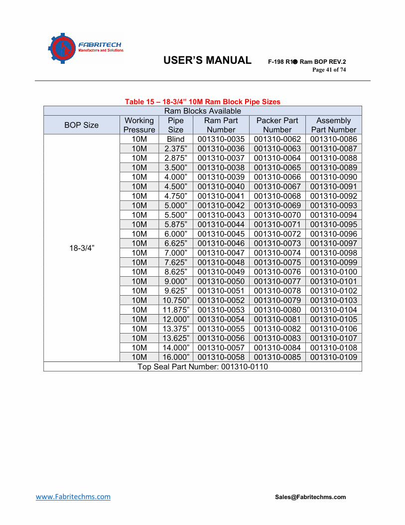
Table 15 – 18-3/4” 10M Ram Block Pipe Sizes Ram Blocks Available
BOP Size Working Pressure
Pipe Size
Ram Part Number
Packer Part Number
Assembly Part Number
18-3/4”
10M Blind 001310-0035 001310-0062 001310-0086 10M 2.375” 001310-0036 001310-0063 001310-0087 10M 2.875” 001310-0037 001310-0064 001310-0088 10M 3.500” 001310-0038 001310-0065 001310-0089 10M 4.000” 001310-0039 001310-0066 001310-0090 10M 4.500” 001310-0040 001310-0067 001310-0091 10M 4.750” 001310-0041 001310-0068 001310-0092 10M 5.000” 001310-0042 001310-0069 001310-0093 10M 5.500” 001310-0043 001310-0070 001310-0094 10M 5.875” 001310-0044 001310-0071 001310-0095 10M 6.000” 001310-0045 001310-0072 001310-0096 10M 6.625” 001310-0046 001310-0073 001310-0097 10M 7.000” 001310-0047 001310-0074 001310-0098 10M 7.625” 001310-0048 001310-0075 001310-0099 10M 8.625” 001310-0049 001310-0076 001310-0100 10M 9.000” 001310-0050 001310-0077 001310-0101 10M 9.625” 001310-0051 001310-0078 001310-0102 10M 10.750” 001310-0052 001310-0079 001310-0103 10M 11.875” 001310-0053 001310-0080 001310-0104 10M 12.000” 001310-0054 001310-0081 001310-0105 10M 13.375” 001310-0055 001310-0082 001310-0106 10M 13.625” 001310-0056 001310-0083 001310-0107 10M 14.000” 001310-0057 001310-0084 001310-0108 10M 16.000” 001310-0058 001310-0085 001310-0109
Top Seal Part Number: 001310-0110
USER’S MANUAL F-198 R1â Ram BOP REV.2 Page 42 of 74
www.Fabritechms.com [email protected]
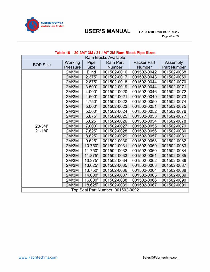
Table 16 – 20-3/4” 3M / 21-1/4” 2M Ram Block Pipe Sizes Ram Blocks Available
BOP Size Working Pressure
Pipe Size
Ram Part Number
Packer Part Number
Assembly Part Number
20-3/4” 21-1/4”
2M/3M Blind 001502-0016 001502-0042 001502-0068 2M/3M 2.375” 001502-0017 001502-0043 001502-0069 2M/3M 2.875” 001502-0018 001502-0044 001502-0070 2M/3M 3.500” 001502-0019 001502-0044 001502-0071 2M/3M 4.000” 001502-0020 001502-0046 001502-0072 2M/3M 4.500” 001502-0021 001502-0049 001502-0073 2M/3M 4.750” 001502-0022 001502-0050 001502-0074 2M/3M 5.000” 001502-0023 001502-0051 001502-0075 2M/3M 5.500” 001502-0024 001502-0052 001502-0076 2M/3M 5.875” 001502-0025 001502-0053 001502-0077 2M/3M 6.625” 001502-0026 001502-0054 001502-0078 2M/3M 7.000” 001502-0027 001502-0055 001502-0079 2M/3M 7.625” 001502-0028 001502-0056 001502-0080 2M/3M 8.625” 001502-0029 001502-0057 001502-0081 2M/3M 9.625” 001502-0030 001502-0058 001502-0082 2M/3M 10.750” 001502-0031 001502-0059 001502-0083 2M/3M 11.750” 001502-0032 001502-0060 001502-0084 2M/3M 11.875” 001502-0033 001502-0061 001502-0085 2M/3M 13.375” 001502-0034 001502-0062 001502-0086 2M/3M 13.625” 001502-0035 001502-0063 001502-0087 2M/3M 13.750” 001502-0036 001502-0064 001502-0088 2M/3M 14.000” 001502-0037 001502-0065 001502-0089 2M/3M 16.000” 001502-0038 001502-0066 001502-0090 2M/3M 18.625” 001502-0039 001502-0067 001502-0091
Top Seal Part Number: 001502-0092
USER’S MANUAL F-198 R1â Ram BOP REV.2 Page 43 of 74
www.Fabritechms.com [email protected]
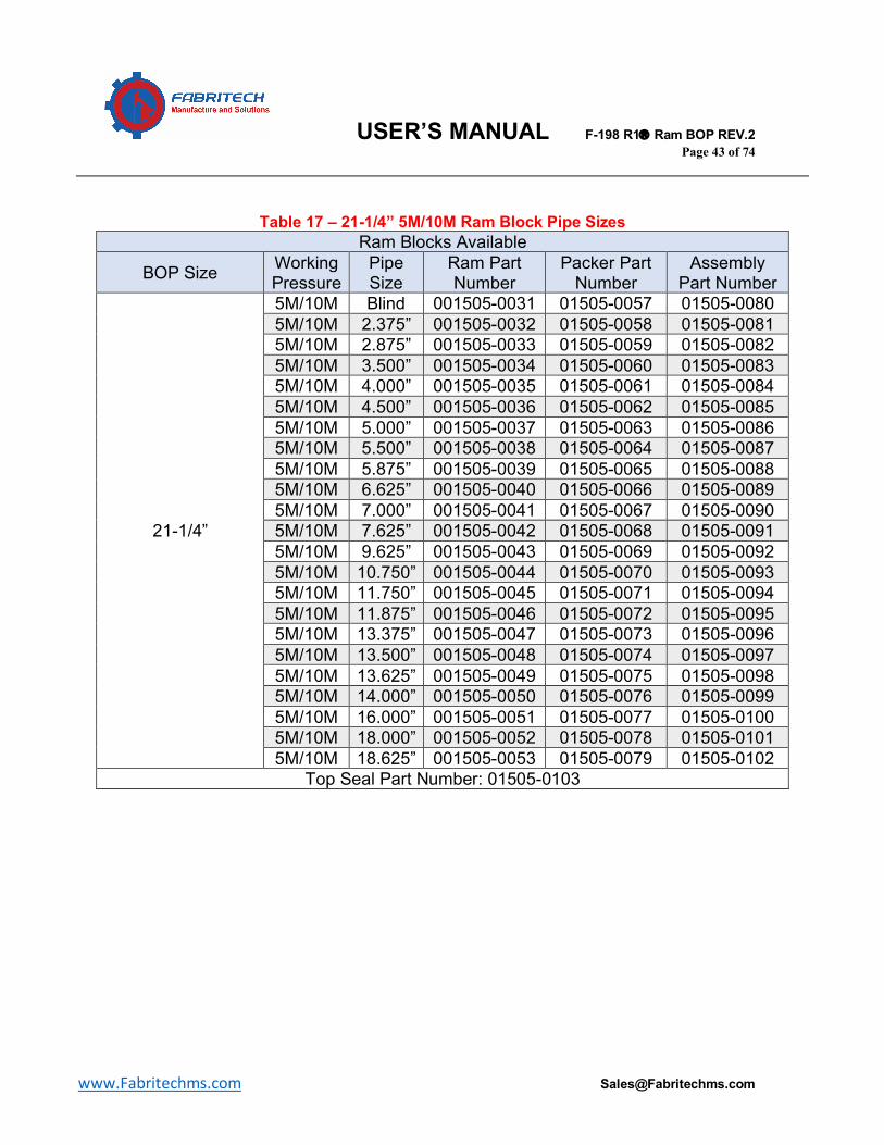
Table 17 – 21-1/4” 5M/10M Ram Block Pipe Sizes Ram Blocks Available
BOP Size Working Pressure
Pipe Size
Ram Part Number
Packer Part Number
Assembly Part Number
21-1/4”
5M/10M Blind 001505-0031 01505-0057 01505-0080 5M/10M 2.375” 001505-0032 01505-0058 01505-0081 5M/10M 2.875” 001505-0033 01505-0059 01505-0082 5M/10M 3.500” 001505-0034 01505-0060 01505-0083 5M/10M 4.000” 001505-0035 01505-0061 01505-0084 5M/10M 4.500” 001505-0036 01505-0062 01505-0085 5M/10M 5.000” 001505-0037 01505-0063 01505-0086 5M/10M 5.500” 001505-0038 01505-0064 01505-0087 5M/10M 5.875” 001505-0039 01505-0065 01505-0088 5M/10M 6.625” 001505-0040 01505-0066 01505-0089 5M/10M 7.000” 001505-0041 01505-0067 01505-0090 5M/10M 7.625” 001505-0042 01505-0068 01505-0091 5M/10M 9.625” 001505-0043 01505-0069 01505-0092 5M/10M 10.750” 001505-0044 01505-0070 01505-0093 5M/10M 11.750” 001505-0045 01505-0071 01505-0094 5M/10M 11.875” 001505-0046 01505-0072 01505-0095 5M/10M 13.375” 001505-0047 01505-0073 01505-0096 5M/10M 13.500” 001505-0048 01505-0074 01505-0097 5M/10M 13.625” 001505-0049 01505-0075 01505-0098 5M/10M 14.000” 001505-0050 01505-0076 01505-0099 5M/10M 16.000” 001505-0051 01505-0077 01505-0100 5M/10M 18.000” 001505-0052 01505-0078 01505-0101 5M/10M 18.625” 001505-0053 01505-0079 01505-0102
Top Seal Part Number: 01505-0103
USER’S MANUAL F-198 R1â Ram BOP REV.2 Page 44 of 74
www.Fabritechms.com [email protected]
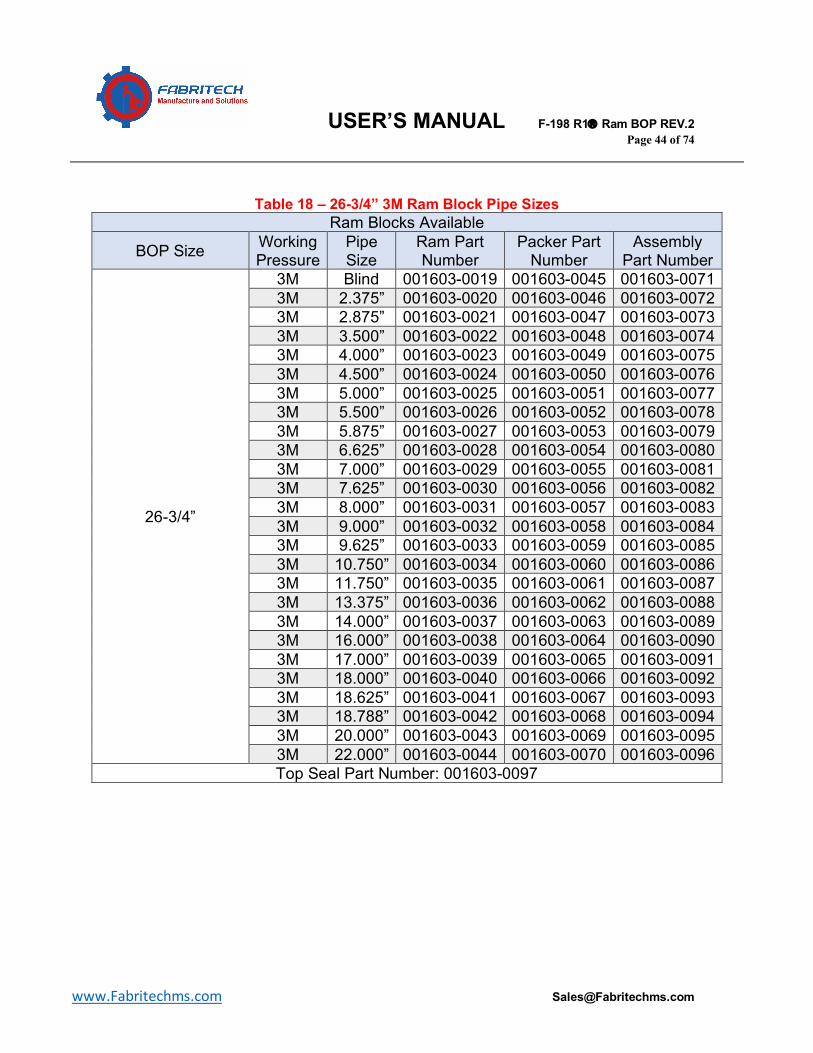
Table 18 – 26-3/4” 3M Ram Block Pipe Sizes Ram Blocks Available
BOP Size Working Pressure
Pipe Size
Ram Part Number
Packer Part Number
Assembly Part Number
26-3/4”
3M Blind 001603-0019 001603-0045 001603-0071 3M 2.375” 001603-0020 001603-0046 001603-0072 3M 2.875” 001603-0021 001603-0047 001603-0073 3M 3.500” 001603-0022 001603-0048 001603-0074 3M 4.000” 001603-0023 001603-0049 001603-0075 3M 4.500” 001603-0024 001603-0050 001603-0076 3M 5.000” 001603-0025 001603-0051 001603-0077 3M 5.500” 001603-0026 001603-0052 001603-0078 3M 5.875” 001603-0027 001603-0053 001603-0079 3M 6.625” 001603-0028 001603-0054 001603-0080 3M 7.000” 001603-0029 001603-0055 001603-0081 3M 7.625” 001603-0030 001603-0056 001603-0082 3M 8.000” 001603-0031 001603-0057 001603-0083 3M 9.000” 001603-0032 001603-0058 001603-0084 3M 9.625” 001603-0033 001603-0059 001603-0085 3M 10.750” 001603-0034 001603-0060 001603-0086 3M 11.750” 001603-0035 001603-0061 001603-0087 3M 13.375” 001603-0036 001603-0062 001603-0088 3M 14.000” 001603-0037 001603-0063 001603-0089 3M 16.000” 001603-0038 001603-0064 001603-0090 3M 17.000” 001603-0039 001603-0065 001603-0091 3M 18.000” 001603-0040 001603-0066 001603-0092 3M 18.625” 001603-0041 001603-0067 001603-0093 3M 18.788” 001603-0042 001603-0068 001603-0094 3M 20.000” 001603-0043 001603-0069 001603-0095 3M 22.000” 001603-0044 001603-0070 001603-0096 Top Seal Part Number: 001603-0097
USER’S MANUAL F-198 R1â Ram BOP REV.2 Page 45 of 74
www.Fabritechms.com [email protected]
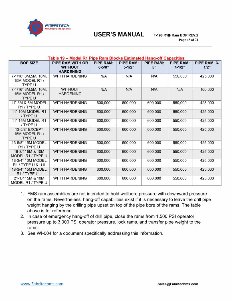
Table 19 – Model R1 Pipe Ram Blocks Estimated Hang-off Capacities BOP SIZE PIPE RAM WITH OR
WITHOUT HARDENING
PIPE RAM: 6-5/8”
PIPE RAM: 5-1/2”
PIPE RAM: 5”
PIPE RAM: 4-1/2”
PIPE RAM: 3-1/2”
7-1/16” 3M,5M, 10M, 15M MODEL R1 /
TYPE U
WITH HARDENING N/A N/A N/A 550,000 425,000
7-1/16” 3M,5M, 10M, 15M MODEL R1 /
TYPE U
WITHOUT HARDENING
N/A N/A N/A N/A 100,000
11” 3M & 5M MODEL R1 / TYPE U
WITH HARDENING 600,000 600,000 600,000 550,000 425,000
11” 10M MODEL R1 / TYPE U
WITH HARDENING 600,000 600,000 600,000 550,000 425,000
11” 15M MODEL R1 / TYPE U
WITH HARDENING 600,000 600,000 600,000 550,000 425,000
13-5/8” EXCEPT 15M MODEL R1 /
TYPE U
WITH HARDENING 600,000 600,000 600,000 550,000 425,000
13-5/8” 15M MODEL R1 / TYPE U
WITH HARDENING 600,000 600,000 600,000 550,000 425,000
16-3/4” 5M & 10M MODEL R1 / TYPE U
WITH HARDENING 600,000 600,000 600,000 550,000 425,000
18-3/4” 10M MODEL R1 / TYPE U & U II
WITH HARDENING 600,000 600,000 600,000 550,000 425,000
18-3/4” 15M MODEL R1 / TYPE U II
WITH HARDENING 600,000 600,000 600,000 550,000 425,000
21-1/4” 5M & 10M MODEL R1 / TYPE U
WITH HARDENING 600,000 600,000 600,000 550,000 425,000
1. FMS ram assemblies are not intended to hold wellbore pressure with downward pressure
on the rams. Nevertheless, hang-off capabilities exist if it is necessary to leave the drill pipe weight hanging by the drilling pipe upset on top of the pipe bore of the rams. The table above is for reference.
2. In case of emergency hang-off of drill pipe, close the rams from 1,500 PSI operator pressure up to 3,000 PSI operator pressure, lock rams, and transfer pipe weight to the rams.
3. See WI-004 for a document specifically addressing this information.
USER’S MANUAL F-198 R1â Ram BOP REV.2 Page 46 of 74
www.Fabritechms.com [email protected]
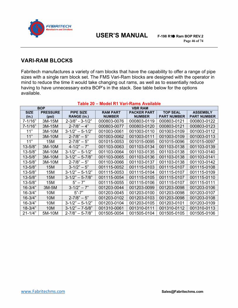
VARI-RAM BLOCKS Fabritech manufactures a variety of ram blocks that have the capability to offer a range of pipe sizes with a single ram block set. The FMS Vari-Ram blocks are designed with the operator in mind to reduce the time it would take changing out rams, as well as to essentially reduce having to have unnecessary extra BOP’s in the stack. See table below for the options available.
Table 20 – Model R1 Vari-Rams Available BOP VBR RAM
SIZE (in.)
PRESSURE (psi)
PIPE SIZE RANGE (in.)
RAM PART NUMBER
PACKER PART NUMBER
TOP SEAL PART NUMBER
ASSEMBLY PART NUMBER
7-1/16” 3M-15M 2-3/8” - 3-1/2” 000803-0076 000803-0119 000803-0121 000803-0122 7-1/16” 3M-15M 2-7/8” – 4” 000803-0077 000803-0120 000803-0121 000803-0123
11” 3M-10M 3-1/2” – 5-1/2” 001003-0061 001003-0110 001003-0109 001003-0112 11” 3M-10M 2-7/8” – 5” 001003-0062 001003-0111 001003-0109 001003-0113 11” 15M 2-7/8” – 5” 001015-0053 001015-0095 001015-0096 001015-0097
13-5/8” 3M-10M 4-1/2” – 7” 001103-0063 001103-0134 001103-0138 001103-0139 13-5/8” 3M-10M 3-1/2” – 5-1/2” 001103-0064 001103-0135 001103-0138 001103-0140 13-5/8” 3M-10M 3-1/2” – 5-7/8” 001103-0065 001103-0136 001103-0138 001103-0141 13-5/8” 3M-10M 2-7/8” – 5” 001103-0066 001103-0137 001103-0138 001103-0142 13-5/8” 15M 3-1/2” – 5” 001115-0052 001115-0103 001115-0107 001115-0108 13-5/8” 15M 3-1/2” – 5-1/2” 001115-0053 001115-0104 001115-0107 001115-0109 13-5/8” 15M 3-1/2” – 5-7/8” 001115-0054 001115-0105 001115-0107 001115-0110 13-5/8” 15M 5” – 7” 001115-0055 001115-0106 001115-0107 001115-0111 16-3/4” 3M-5M 3-1/2” – 7” 001203-0044 001203-0099 001203-0098 001203-0106 16-3/4” 10M 5”-7” 001203-0045 001203-0100 001203-0098 001203-0107 16-3/4” 10M 2-7/8” – 5” 001203-0102 001203-0103 001203-0098 001203-0108 16-3/4” 10M 3-1/2” – 5-1/2” 001203-0104 001203-0105 001203-0101 001203-0109 18-3/4” 10M 3-1/2” – 7-5/8” 001310-0061 001310-0111 001310-0112 001310-0113 21-1/4” 5M-10M 2-7/8” – 5-7/8” 001505-0054 001505-0104 001505-0105 001505-0106
USER’S MANUAL F-198 R1â Ram BOP REV.2 Page 47 of 74
www.Fabritechms.com [email protected]
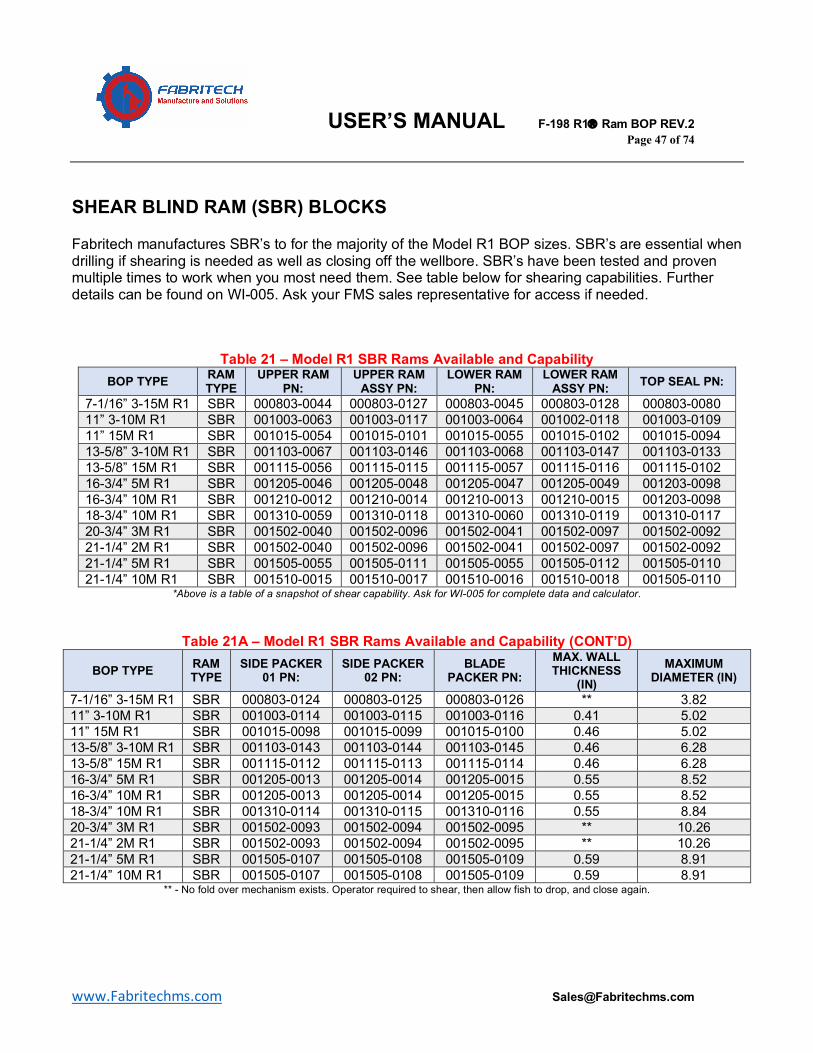
SHEAR BLIND RAM (SBR) BLOCKS Fabritech manufactures SBR’s to for the majority of the Model R1 BOP sizes. SBR’s are essential when drilling if shearing is needed as well as closing off the wellbore. SBR’s have been tested and proven multiple times to work when you most need them. See table below for shearing capabilities. Further details can be found on WI-005. Ask your FMS sales representative for access if needed.
Table 21 – Model R1 SBR Rams Available and Capability BOP TYPE RAM
TYPE UPPER RAM
PN: UPPER RAM
ASSY PN: LOWER RAM
PN: LOWER RAM
ASSY PN: TOP SEAL PN:
7-1/16” 3-15M R1 SBR 000803-0044 000803-0127 000803-0045 000803-0128 000803-0080 11” 3-10M R1 SBR 001003-0063 001003-0117 001003-0064 001002-0118 001003-0109 11” 15M R1 SBR 001015-0054 001015-0101 001015-0055 001015-0102 001015-0094 13-5/8” 3-10M R1 SBR 001103-0067 001103-0146 001103-0068 001103-0147 001103-0133 13-5/8” 15M R1 SBR 001115-0056 001115-0115 001115-0057 001115-0116 001115-0102 16-3/4” 5M R1 SBR 001205-0046 001205-0048 001205-0047 001205-0049 001203-0098 16-3/4” 10M R1 SBR 001210-0012 001210-0014 001210-0013 001210-0015 001203-0098 18-3/4” 10M R1 SBR 001310-0059 001310-0118 001310-0060 001310-0119 001310-0117 20-3/4” 3M R1 SBR 001502-0040 001502-0096 001502-0041 001502-0097 001502-0092 21-1/4” 2M R1 SBR 001502-0040 001502-0096 001502-0041 001502-0097 001502-0092 21-1/4” 5M R1 SBR 001505-0055 001505-0111 001505-0055 001505-0112 001505-0110 21-1/4” 10M R1 SBR 001510-0015 001510-0017 001510-0016 001510-0018 001505-0110
*Above is a table of a snapshot of shear capability. Ask for WI-005 for complete data and calculator.
Table 21A – Model R1 SBR Rams Available and Capability (CONT’D)
BOP TYPE RAM TYPE
SIDE PACKER 01 PN:
SIDE PACKER 02 PN:
BLADE PACKER PN:
MAX. WALL THICKNESS
(IN) MAXIMUM
DIAMETER (IN)
7-1/16” 3-15M R1 SBR 000803-0124 000803-0125 000803-0126 ** 3.82 11” 3-10M R1 SBR 001003-0114 001003-0115 001003-0116 0.41 5.02 11” 15M R1 SBR 001015-0098 001015-0099 001015-0100 0.46 5.02 13-5/8” 3-10M R1 SBR 001103-0143 001103-0144 001103-0145 0.46 6.28 13-5/8” 15M R1 SBR 001115-0112 001115-0113 001115-0114 0.46 6.28 16-3/4” 5M R1 SBR 001205-0013 001205-0014 001205-0015 0.55 8.52 16-3/4” 10M R1 SBR 001205-0013 001205-0014 001205-0015 0.55 8.52 18-3/4” 10M R1 SBR 001310-0114 001310-0115 001310-0116 0.55 8.84 20-3/4” 3M R1 SBR 001502-0093 001502-0094 001502-0095 ** 10.26 21-1/4” 2M R1 SBR 001502-0093 001502-0094 001502-0095 ** 10.26 21-1/4” 5M R1 SBR 001505-0107 001505-0108 001505-0109 0.59 8.91 21-1/4” 10M R1 SBR 001505-0107 001505-0108 001505-0109 0.59 8.91
** - No fold over mechanism exists. Operator required to shear, then allow fish to drop, and close again.
USER’S MANUAL F-198 R1â Ram BOP REV.2 Page 48 of 74
www.Fabritechms.com [email protected]
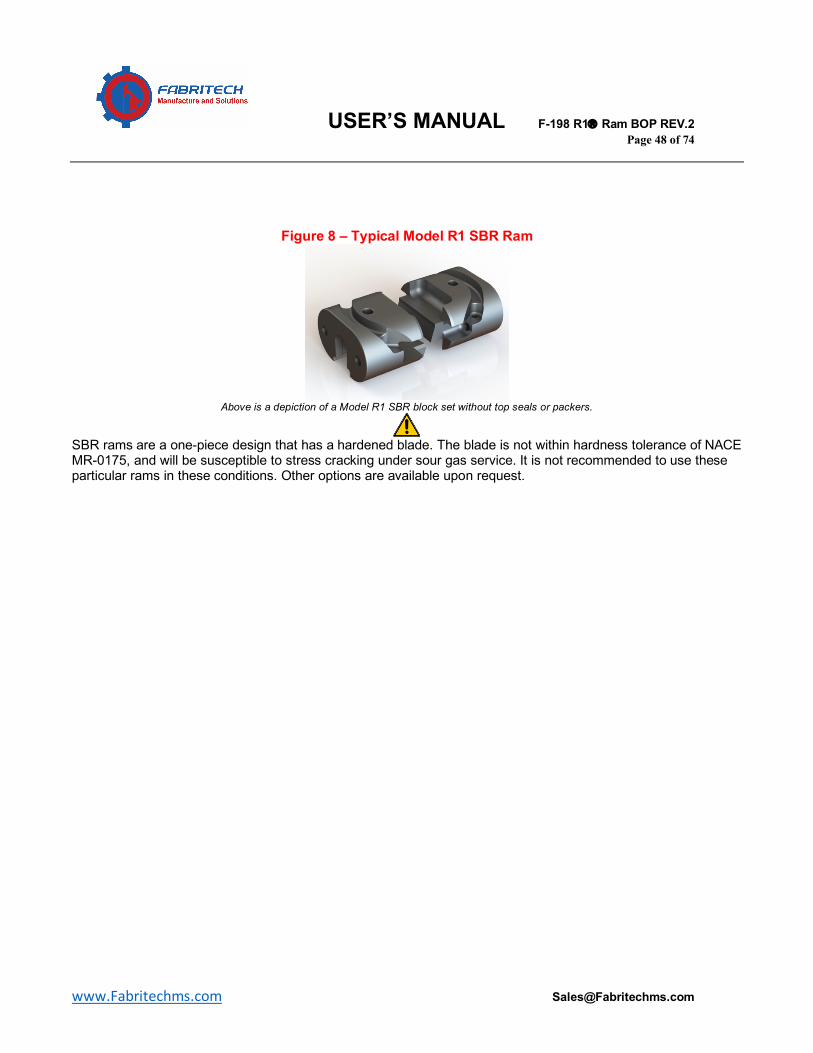
Figure 8 – Typical Model R1 SBR Ram
Above is a depiction of a Model R1 SBR block set without top seals or packers.
SBR rams are a one-piece design that has a hardened blade. The blade is not within hardness tolerance of NACE MR-0175, and will be susceptible to stress cracking under sour gas service. It is not recommended to use these particular rams in these conditions. Other options are available upon request.
USER’S MANUAL F-198 R1â Ram BOP REV.2 Page 49 of 74
www.Fabritechms.com [email protected]
Operational Characteristics This section is intended to outline the operational characteristics of the Model R1 Ram BOP. All data in this section is derived from testing performed on prototypes, and may vary depending on the actual condition the BOP is experiencing. It is the end user’s responsibility to monitor and document wear as well as determine when to service the BOP. Sealing Characteristics Test The Model R1 BOP was utilized with a set of 3.5” pipe bore rams. This test proved that 98 psi was required to prevent a leak at 0 psi wellbore pressure. It was also discovered that a minimum of 300 psi operating pressure is required to effect a seal at rated working pressure. Fatigue Test The Model R1 BOP was utilized with a set of 3.5” pipe bore rams for the fatigue test. This test proved that pipe ram, packers, top seals, and bonnets successfully completed the fatigue testing with 574 high- and low-pressure tests, 82 fatigue cycles, and 11 ram locking tests. Stripping Test The Model R1 BOP and a set of 3.5” pipe bore rams were utilized to perform the stripping test. A 3.5” X 32’ test mandrel was reciprocated to simulate stripping. This test accomplished approximately 6,382 ft. of pipe stripped. Hang-Off Test Hang-off testing has not been physically performed, but has been calculated using computer software, as well as historical performance of similar designs. Testing can be performed if required by customer. Ram Locking Device Test Ram locking device test has proven 200 cycles without failure. Ram Access Test Testing was performed and ram access testing performed successfully without failure 200 cycles and 10 wellbore pressure tests.

USER’S MANUAL F-198 R1â Ram BOP REV.2 Page 50 of 74
www.Fabritechms.com [email protected]
BOP Temperature Rating The BOP can be temperature rated at many different temperature ratings. The particular BOP that was used in prototype testing is temperature rated at T50/250. Ram Assembly Temperature Testing The ram assemblies can be temperature rated at many different temperature ratings. The particular Ram Assembly that was used in prototype testing is temperature rated at T75/250.
USER’S MANUAL F-198 R1â Ram BOP REV.2 Page 51 of 74
www.Fabritechms.com [email protected]
Section D: Maintenance A preventive maintenance program is designed to keep equipment running optimally and safely when the equipment functionality is crucial for mitigating emergency situations. It is important to follow the recommendations set forth, as well as those outlined by API STD 53 latest edition.
§ Weekly • Function and pressure test Model R1 Ram BOP per weekly, and or per API STD
53 latest edition prescribed frequencies. § Monthly
• All BOP’s should be inspected for anomalies and accumulation of medium deposits on a regular basis as per below by rig personnel.
o Function and pressure test Model R1 Ram BOP per API STD 53 latest edition frequencies.
o Avoid mud, oil, and or other mediums from setting by rinsing the BOP with water and performing several function tests. If water alone will not suffice, remove ram blocks and wash interior.
o Check all nuts and studs for damaged threads by visual inspection STD 53. o Visually inspect any readily visible BOP components for excess wear (Min.
1/8” in. wear for bore) o Visually inspect the packers for cracks, chunking, or splitting. o Replace packers as deemed necessary. o Perform every time prior to putting into operational service on the wellhead
STD 53. § Yearly
• All BOP’s should be inspected yearly in anticipation for the 3-year maintenance. The yearly inspection goes deeper in scope than the monthly maintenance and is to be performed by rig personnel or at
o Clean all ring grooves and visually inspect for dings and major scratches. It is recommended to perform a penetrant test of ring grooves. Document all findings.
o Check all nuts and studs for damaged threads by visual inspection STD 53.
USER’S MANUAL F-198 R1â Ram BOP REV.2 Page 52 of 74
www.Fabritechms.com [email protected]
o Remove ram blocks and clean all bore and cavity areas thoroughly with water. Emery cloth use is recommended for cleaning light corrosion and scratches.
o Replace all rubber seals, gaskets, and O-rings. o Inspect all bore and cavity areas for any deep scratches or dings. Inspect
ram blocks for any dings and scratches, and clean or replace if needed. Ram packers may be replaced if deemed necessary. Document all findings.
o Perform hydraulic pressure test and wellbore pressure test of low and high pressure at a minimum of 5 minutes. Document findings STD 53.
§ Three Years (Or approximately 800 operating cycles) • All BOP’s are to be scheduled a three-year maintenance program where Fabritech
completely disassembles the BOP, cleans, and inspects the BOP. All elastomers/seals and packers are replaced, and parts are replaced or fixed as necessary. Dimensional inspection of the entire BOP components is performed, as well as hydraulic and wellbore pressure tests prior to factory acceptance and certification. Studs and nuts are replaced STD 53.
USER’S MANUAL F-198 R1â Ram BOP REV.2 Page 53 of 74
www.Fabritechms.com [email protected]
CLEANING & LUBRICATING RECOMMENDATIONS
Table 22 – Cleaning and Lubricating Recommendations PART METHOD LUBRICANT
MODEL R1® RAM BOP – Exterior Surface
Steam or High-Pressure Water
N/A
MODEL R1® RAM BOP – Ram Cavities
Steam or High-Pressure Water
Grease or Ram Lube
MODEL R1® RAM Blocks Steam or High-Pressure Water
Grease or Ram Lube
Bonnet Bolts/Studs/Nuts Wire Brush or Water Grease Ring Grooves Emery Cloth Grease for preservation All other parts internal surfaces (no sealing areas)
Steam or High-Pressure Water
Grease
All other parts internal surfaces (Sealing Areas)
Emery Cloth SAE-10W Hydraulic Oil
Lifting Eye Threads Wire Brush or Water Grease for preservation Seals (Non-Metallic) Damp Cloth SAE-10W Hydraulic Oil Ram Packers/Top Seals High-Pressure Water Grease Wear Band Grooves Cleaning Solvent SAE-10W Hydraulic Oil

USER’S MANUAL F-198 R1â Ram BOP REV.2 Page 54 of 74
www.Fabritechms.com [email protected]
TROUBLESHOOTING Table 23 - Troubleshooting
Issue Possible Cause Corrective Action
Wellbore fluid leaks from top or bottom outlet
Bolts not fastened enough. Tighten bolts to recommended torque.
Improper seal from gasket or flange face.
Clean or replace gasket, and or clean ring groove.
Worn ring gasket. Replace ring gasket
Wellbore fluid leaking through ram packers when rams are
closed
Hydraulic pressure not at required pressure.
Increase hydraulic pressure, not exceeding 3,000 psi.
Ram packers need replacing. Replace ram packers.
Hydraulic fluid leaking out of weep hole on the bottom of the
intermediate flange
Connecting rod O-ring needs replacing. Replace O-ring.
Wellbore fluid leaking between intermediate flange and body
Bonnet bolts not tight enough. Tighten bolts to recommended torque.
Bonnet seal is not functioning properly.
Open bonnet, remove and clean bonnet seal. Reinstall bonnet
seal. Bonnet seal needs replacement. Replace bonnet seal.
Hydraulic fluid leaking between intermediate flange and bonnet
Operating cylinder and or ram change cylinder seals need
replacement.
Replace operating cylinder and or ram change cylinder seals.
Hydraulic fluid leaking around the locking screw housing
O-ring and seal between bonnet and lock screw housing need
replacement.
Replace O-ring and seal between bonnet and lock screw
housing.
Fluid leaks from pipe plug
Pipe plug is not tight enough. Properly torque pipe plug.
Thread sealing tape has failed. Replace thread sealing tape on cleaned threads.
USER’S MANUAL F-198 R1â Ram BOP REV.2 Page 55 of 74
www.Fabritechms.com [email protected]
STORAGE OF BOP ASSEMBLY When anticipating storage, it is imperative that the preventer be prepared for storage depending on the time frame that the preventer will be in storage. See below for suitable recommendations. MEDIUM-TERM (LESS THAN 3 MONTHS)
1. Open the bonnets and remove the ram blocks. 2. Remove packers and top seals from ram blocks and wash/clean ram block
subassemblies. 3. Apply heavy grease to ram block bodies. (not recommended to store inside BOP) 4. Clean both inside and outside machine finished surfaces of the BOP, ensuring
there is no moisture left. 5. Inspect ram cavities and through-bore for any nicks, removing any burrs with 60
grit paper. 6. Apply heavy grease to ram bore cavities. 7. Apply heavy grease to end and outlet connection sealing faces, and cover with
flange protectors. 8. Flush the hydraulic system using clean operating fluid. 9. Partially fill hydraulic system with corrosion inhibiting fluid, preferably with vapor
phase inhibitor. 10. Leave operating piston in the open position. 11. Log date placed in storage.
LONG-TERM (MORE THAN 3 MONTHS)
1. Open the bonnets and remove the ram blocks. 2. Remove packers and top seals from ram blocks and wash/clean ram block
subassemblies. 3. Apply heavy grease to ram block bodies. (not recommended to store inside BOP) 4. Clean both inside and outside machine finished surfaces of the BOP, ensuring
there is no moisture left. 5. Inspect ram cavities and through-bore for any nicks, removing any burrs with 60
grit paper. 6. Apply heavy grease to ram bore cavities. 7. Apply heavy grease to end and outlet connection sealing faces, and cover with
flange protectors. 8. Flush the hydraulic system using clean operating fluid. 9. Fill hydraulic system with corrosion inhibiting fluid, preferably with vapor phase
inhibitor. 10. Leave operating piston in the open position. 11. Log date placed in storage.
USER’S MANUAL F-198 R1â Ram BOP REV.2 Page 56 of 74
www.Fabritechms.com [email protected]
STORAGE OF ELASTOMERS When anticipating storage of elastomers, it is important to plan a storage space that is free from ultraviolet light, contaminants, as well as extreme temperatures. RECOMMENDATIONS
1. Fresh, dark, and dry areas. 2. Ideally, the storage area should be 40° - 80° F. 3. Avoid any sunlight, or artificial fluorescent lights. 4. Store elastomers in relaxed conditions. 5. Avoid placing elastomers around ozone. 6. Keep elastomers clean and free of solvents, oils, and greases. 7. Ensure elastomers are not tacky or cracked prior to installation, and replace
those that show these properties. 8. Keep a visual inspection log and ensure yearly inspection at minimum.
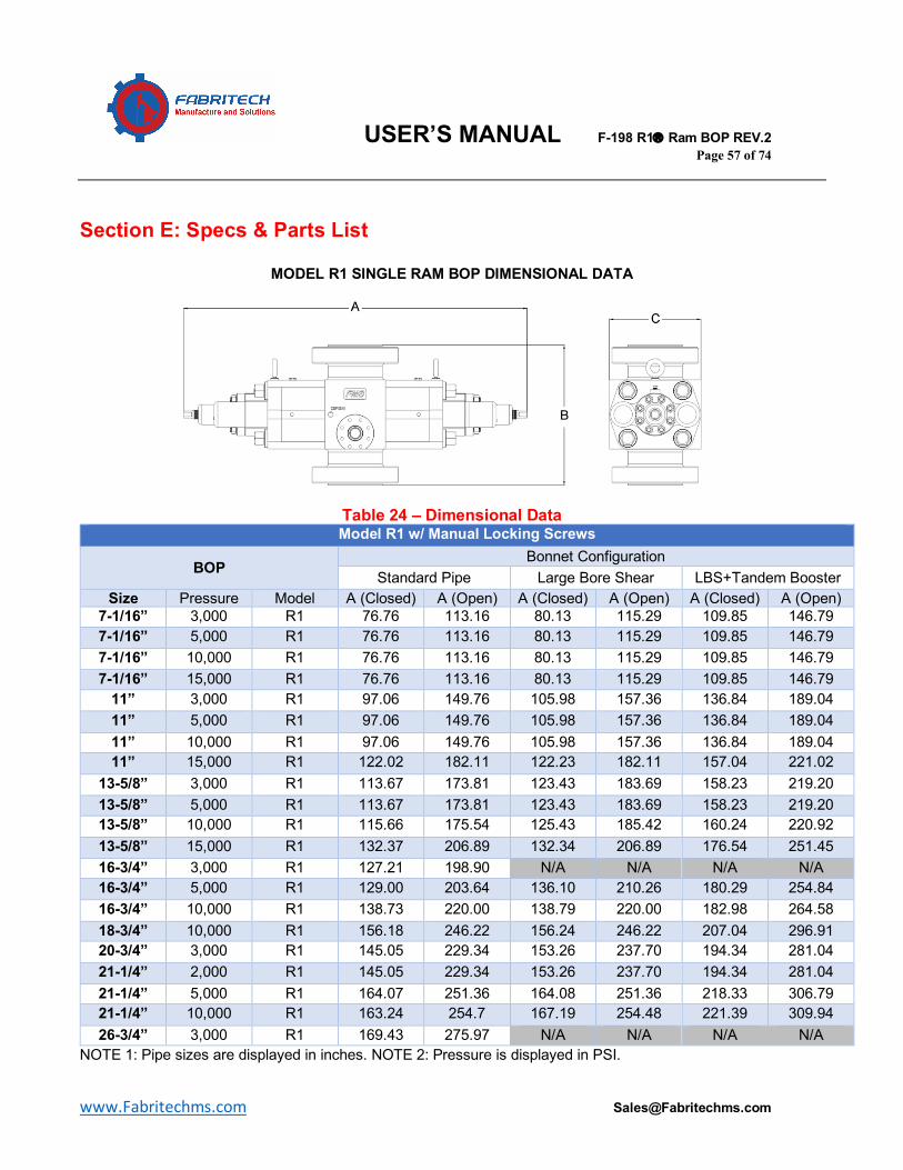
USER’S MANUAL F-198 R1â Ram BOP REV.2 Page 57 of 74
www.Fabritechms.com [email protected]
Section E: Specs & Parts List
MODEL R1 SINGLE RAM BOP DIMENSIONAL DATA
Table 24 – Dimensional Data Model R1 w/ Manual Locking Screws
BOP Bonnet Configuration
Standard Pipe Large Bore Shear LBS+Tandem Booster Size Pressure Model A (Closed) A (Open) A (Closed) A (Open) A (Closed) A (Open)
7-1/16” 3,000 R1 76.76 113.16 80.13 115.29 109.85 146.79 7-1/16” 5,000 R1 76.76 113.16 80.13 115.29 109.85 146.79 7-1/16” 10,000 R1 76.76 113.16 80.13 115.29 109.85 146.79 7-1/16” 15,000 R1 76.76 113.16 80.13 115.29 109.85 146.79
11” 3,000 R1 97.06 149.76 105.98 157.36 136.84 189.04 11” 5,000 R1 97.06 149.76 105.98 157.36 136.84 189.04 11” 10,000 R1 97.06 149.76 105.98 157.36 136.84 189.04 11” 15,000 R1 122.02 182.11 122.23 182.11 157.04 221.02
13-5/8” 3,000 R1 113.67 173.81 123.43 183.69 158.23 219.20 13-5/8” 5,000 R1 113.67 173.81 123.43 183.69 158.23 219.20 13-5/8” 10,000 R1 115.66 175.54 125.43 185.42 160.24 220.92 13-5/8” 15,000 R1 132.37 206.89 132.34 206.89 176.54 251.45 16-3/4” 3,000 R1 127.21 198.90 N/A N/A N/A N/A 16-3/4” 5,000 R1 129.00 203.64 136.10 210.26 180.29 254.84 16-3/4” 10,000 R1 138.73 220.00 138.79 220.00 182.98 264.58 18-3/4” 10,000 R1 156.18 246.22 156.24 246.22 207.04 296.91 20-3/4” 3,000 R1 145.05 229.34 153.26 237.70 194.34 281.04 21-1/4” 2,000 R1 145.05 229.34 153.26 237.70 194.34 281.04 21-1/4” 5,000 R1 164.07 251.36 164.08 251.36 218.33 306.79 21-1/4” 10,000 R1 163.24 254.7 167.19 254.48 221.39 309.94 26-3/4” 3,000 R1 169.43 275.97 N/A N/A N/A N/A
NOTE 1: Pipe sizes are displayed in inches. NOTE 2: Pressure is displayed in PSI.
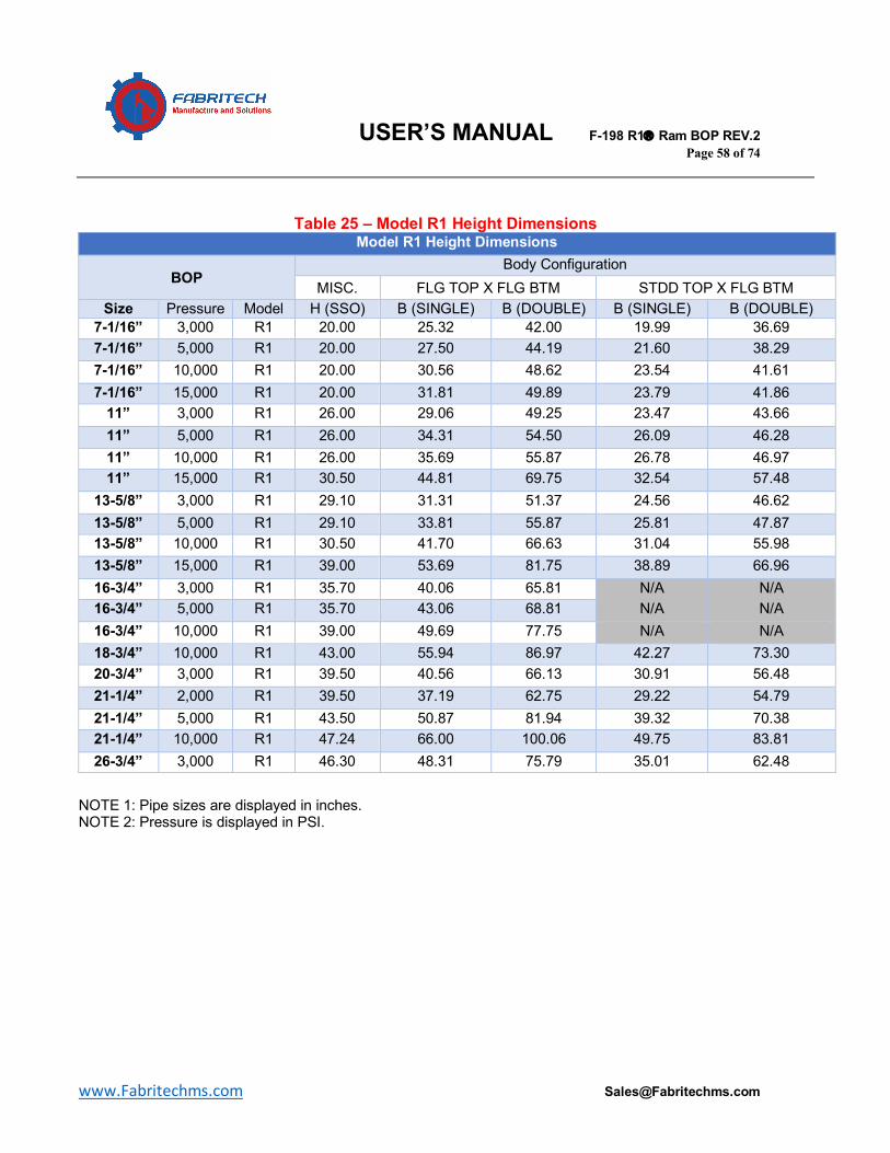
USER’S MANUAL F-198 R1â Ram BOP REV.2 Page 58 of 74
www.Fabritechms.com [email protected]
Table 25 – Model R1 Height Dimensions Model R1 Height Dimensions
BOP Body Configuration
MISC. FLG TOP X FLG BTM STDD TOP X FLG BTM Size Pressure Model H (SSO) B (SINGLE) B (DOUBLE) B (SINGLE) B (DOUBLE)
7-1/16” 3,000 R1 20.00 25.32 42.00 19.99 36.69 7-1/16” 5,000 R1 20.00 27.50 44.19 21.60 38.29 7-1/16” 10,000 R1 20.00 30.56 48.62 23.54 41.61 7-1/16” 15,000 R1 20.00 31.81 49.89 23.79 41.86
11” 3,000 R1 26.00 29.06 49.25 23.47 43.66 11” 5,000 R1 26.00 34.31 54.50 26.09 46.28 11” 10,000 R1 26.00 35.69 55.87 26.78 46.97 11” 15,000 R1 30.50 44.81 69.75 32.54 57.48
13-5/8” 3,000 R1 29.10 31.31 51.37 24.56 46.62 13-5/8” 5,000 R1 29.10 33.81 55.87 25.81 47.87 13-5/8” 10,000 R1 30.50 41.70 66.63 31.04 55.98 13-5/8” 15,000 R1 39.00 53.69 81.75 38.89 66.96 16-3/4” 3,000 R1 35.70 40.06 65.81 N/A N/A 16-3/4” 5,000 R1 35.70 43.06 68.81 N/A N/A 16-3/4” 10,000 R1 39.00 49.69 77.75 N/A N/A 18-3/4” 10,000 R1 43.00 55.94 86.97 42.27 73.30 20-3/4” 3,000 R1 39.50 40.56 66.13 30.91 56.48 21-1/4” 2,000 R1 39.50 37.19 62.75 29.22 54.79 21-1/4” 5,000 R1 43.50 50.87 81.94 39.32 70.38 21-1/4” 10,000 R1 47.24 66.00 100.06 49.75 83.81 26-3/4” 3,000 R1 46.30 48.31 75.79 35.01 62.48
NOTE 1: Pipe sizes are displayed in inches. NOTE 2: Pressure is displayed in PSI.
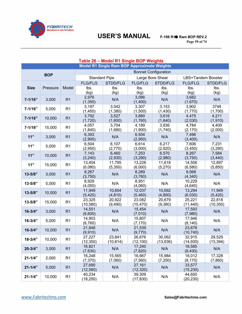
USER’S MANUAL F-198 R1â Ram BOP REV.2 Page 59 of 74
www.Fabritechms.com [email protected]
Table 26 – Model R1 Single BOP Weights Model R1 Single Ram BOP Approximate Weights
BOP Bonnet Configuration
Standard Pipe Large Bore Shear LBS+Tandem Booster
Size Pressure Model FLG/FLG STDD/FLG FLG/FLG STDD/FLG FLG/FLG STDD/FLG
lbs. (kg)
lbs. (kg)
lbs. (kg)
lbs. (kg)
lbs. (kg)
lbs. (kg)
7-1/16” 3,000 R1 2,976 (1,350) N/A 3,086
(1,400) N/A 3,682 (1,670) N/A
7-1/16” 5,000 R1 3,197 (1,450)
3,042 (1,380)
3,307 (1,500)
3,153 (1,430)
3,902 (1,770)
3748 (1,700)
7-1/16” 10,000 R1 3,792 (1,720)
3,527 (1,600)
3,880 (1,760)
3,616 (1,640)
4,475 (2,030)
4,211 (1,910)
7-1/16” 15,000 R1 4,057 (1,840)
3,704 (1,680)
4,189 (1,900)
3,836 (1,740)
4,784 (2,170)
4,409 (2,000)
11” 3,000 R1 6,393 (2,900) N/A 6,504
(2,950) N/A 7,496 (3,400) N/A
11” 5,000 R1 6,504 (2,950)
6,107 (2,770)
6,614 (3,000)
6,217 (2,820)
7,606 (3,450)
7,231 (3,280)
11” 10,000 R1 7,143 (3,240)
6,460 (2,930)
7,253 (3,290)
6,570 (2,980)
8,267 (3,750)
7,584 (3,440)
11” 15,000 R1 13,404 (6,080)
11,795 (5,350)
13,228 (6,000)
11,618 (5,270)
14,506 (6,580)
12,897 (5,850)
13-5/8” 3,000 R1 8,267 (3,750) N/A 8,289
(3,760) N/A 9,568 (4,340) N/A
13-5/8” 5,000 R1 8,929 (4,050) N/A 8,951
(4,060) N/A 10,229 (4,640) N/A
13-5/8” 10,000 R1 11,949 (5,420)
10,604 (4,810)
12,037 (5,460)
10,692 (4,850)
13,294 (6,030)
11,949 (5,420)
13-5/8” 15,000 R1 23,325 (10,580)
20,922 (9,490)
23,082 (10,470)
20,679 (9,380)
25,221 (11,440)
22,818 (10,350)
16-3/4” 3,000 R1 14,551 (6,600) N/A 15,454
(7,010) N/A 17,593 (7,980) N/A
16-3/4” 5,000 R1 14,903 (6,760) N/A 15,807
(7,170) N/A 17,946 (8,140) N/A
16-3/4” 10,000 R1 21,848 (9,910) N/A 21,539
(9,770) N/A 23,678 (10,740) N/A
18-3/4” 10,000 R1 27,227 (12,350)
23,841 (10,814)
26,676 (12,100)
30,062 (13,636)
32,915 (14,930)
29,529 (13,394)
20-3/4” 3,000 R1 16,821 (7,630) N/A 17,240
(7,820) N/A 18,585 (8,430) N/A
21-1/4” 2,000 R1 16,248 (7,370)
15,565 (7,060)
16,667 (7,560)
15,984 (7,250)
18,012 (8,170)
17,328 (7,860)
21-1/4” 5,000 R1 27,690 (12,560) N/A 27,161
(12,320) N/A 33,577 (15,230) N/A
21-1/4” 10,000 R1 40,234 (18,250) N/A 39,309
(17,830) N/A 44,600 (20,230) N/A
USER’S MANUAL F-198 R1â Ram BOP REV.2 Page 60 of 74
www.Fabritechms.com [email protected]
26-3/4” 3,000 R1 27,183 (12,330)
24,846 (11,270) N/A N/A N/A N/A
Table 27 – Model R1 Double BOP Weights Model R1 Double Ram BOP Approximate Weights
BOP Bonnet Configuration
Standard Pipe Large Bore Shear LBS+Tandem Booster
Size Pressure Model FLG/FLG STDD/FLG FLG/FLG STDD/FLG FLG/FLG STDD/FLG
lbs. (kg)
lbs. (kg)
lbs. (kg)
lbs. (kg)
lbs. (kg)
lbs. (kg)
7-1/16” 3,000 R1 6,283 (2,850) N/A 6,371
(2,890) N/A 6,967 (3,160) N/A
7-1/16” 5,000 R1 6,504 (2,950)
6,327 (2,870)
6,592 (2,990)
6,415 (2,910)
7,187 (3,260)
7,011 (3,180)
7-1/16” 10,000 R1 7,341 (3,330)
7,099 (3,220)
7,430 (3,370)
7,187 (3,260)
8,025 (3,640)
7,782 (3,530)
7-1/16” 15,000 R1 7,826 (3,550)
7,452 (3,380)
7,871 (3,570)
7,496 (1,740)
8,466 (3,840)
8,091 (3,670)
11” 3,000 R1 12,434 (5,640) N/A 12,610
(5,720) N/A 13,603 (6,170) N/A
11” 5,000 R1 12,677 (5,750)
12,302 (5,580)
12,809 (5,810)
12,423 (5,635)
13,801 (6,260)
13,426 (6,090)
11” 10,000 R1 13,448 (6,100)
12,765 (5,790)
13,558 (6,150)
12,875 (5,840)
14,573 (6,610)
13,889 (6,300)
11” 15,000 R1 24,670 (11,190)
22,807 (10,345)
24,504 (11,115)
22,642 (10,270)
25,772 (11,690)
23,909 (10,845)
13-5/8” 3,000 R1 17,395 (7,890) N/A 17,439
(7,910) N/A 18,717 (8,490) N/A
13-5/8” 5,000 R1 18,034 (8,180) N/A 18,078
(8,200) N/A 19,357 (8,780) N/A
13-5/8” 10,000 R1 22,465 (10,190)
21,253 (9,640)
22,553 (10,230)
21,341 (9,680)
23,810 (10,800)
22,597 (10,250)
13-5/8” 15,000 R1 44,886 (20,360)
42,638 (19,340)
44,655 (20,255)
42,406 (19,235)
46,782 (21,220)
44,534 (20,200)
16-3/4” 3,000 R1 29,300 (13,290) N/A 30,181
(13,690) N/A 32,320 (14,660) N/A
16-3/4” 5,000 R1 29,652 (13,450) N/A 30,534
(13,850) N/A 32,673 (14,820) N/A
16-3/4” 10,000 R1 43,409 (19,690) N/A N/A N/A N/A N/A
18-3/4” 10,000 R1 54,190 (24,580)
50,795 (23,040)
53,639 (24,330)
50,244 (22,790)
59,878 (27,160)
56,483 (25,620)
20-3/4” 3,000 R1 34,172 (15,500) N/A 34,602
(15,695) N/A 35,935 (16,300) N/A
21-1/4” 2,000 R1 33,510 (15,200)
32,937 (14,940)
33,929 (15,390)
33,356 (15,130)
35,274 (16,000)
34,701 (15,740)
21-1/4” 5,000 R1 53,285 N/A 52,911 N/A 59,327 N/A
USER’S MANUAL F-198 R1â Ram BOP REV.2 Page 61 of 74
www.Fabritechms.com [email protected]
(24,170) (24,000) (26,910)
21-1/4” 10,000 R1 73,502 (33,340) N/A 72,576
(32,920) N/A 79,102 (35,880) N/A
26-3/4” 3,000 R1 54,058 (24,520)
51,721 (23,460) N/A N/A N/A N/A
Table 28 – Model R1 BOP Volumetric Data
Model R1 Ram BOP Volumetric Data
BOP Close Area
Open Area
Ram Close
Volume
Ram Open
Volume
Bonnet Close
Volume
Bonnet Open
Volume Close Ratio
Open Ratio
Locking Screw Max
Turns to Lock*
Size WP Model In2 In2 Gal / (L) Gal / (L) lbs. (kg)
lbs. (kg)
7-1/16” 3-15M R1 37.3 35.9 1.4 / (5.3) 1.3 / (4.9) 2.0 / (7.6) 2.7 / (10.2) 6.9 2.9 19.5
11” 3-10M R1 65.0 62.0 3.5 / (13.2) 3.4 / (12.9) 4.6 / (17.4) 6.0 / (22.7) 7.3 3.7 29.4
11” 15M R1 88.0 86.1 5.8 / (22.0) 5.7 / (21.6) 7.5 / (28.4) 9.4 / (35.6) 9.9 3.0 34
13-5/8” 3-5M R1 88.0 82.5 5.9 / (22.3) 5.6 / (21.2) 7.3 / (27.6) 9.5 / (36.0) 7.0 3.6 33.7
13-5/8” 10M R1 88.0 82.5 5.8 / (22.0) 5.5 / (20.8) 7.2 / (27.3) 9.4 / (35.6) 7.0 3.6 33.6
13-5/8” 15M R1 132.9 130.6 10.6 / (40.1) 10.4 / (39.4) 13.7 / (51.9) 17.3 / (51.9) 10.6 4.4 41.7
16-3/4” 3-5M R1 132.9 123.6 11.0 / (41.6) 10.3 / (39.0) 13.5 / (51.1) 17.6 / (66.6) 6.8 2.9 41.9
16-3/4” 10M R1 132.9 123.6 12.9 / (48.8) 12.0 / (45.4) 15.5 (58.7) 20.0 / (75.7) 6.8 2.9 48.7
18-3/4” 10M R1 228.1 210.0 23.1 / (87.4) 21.3 / (80.6) 25.0 / (94.6) 33.3 / (126.1) 7.4 3.6 59.0
20-3/4” 3M R1 88.0 82.5 8.8 / (33.3) 8.2 / (31.0) 13.4 / (50.7) 19.0 / (71.9) 7.0 2.2 47.9
21-1/4” 2M R1 88.0 82.5 8.8 / (33.3) 8.2 / (31.0) 13.4 / (50.7) 19.0 / (71.9) 7.0 2.2 47.9
21-1/4” 5M R1 256.3 233.1 30.3 / (114.7) 27.6 / (104.5) 31.7 / (120.0) 43.4 / (164.3) 7.2 3.8 57.2
21-1/4” 10M R1 256.3 233.1 27.0 / (102.2) 24.6 / (93.1) 29.0 / (109.8) 40.8 / (154.4) 7.2 3.8 58.6
26-3/4” 3M R1 88.0 82.5 10.9 / (41.3) 10.2 / (38.6) 15.4 / (58.3) 26.6 / (100.7) 7.0 1.6 59.7
USER’S MANUAL F-198 R1â Ram BOP REV.2 Page 62 of 74
www.Fabritechms.com [email protected]
Figure 9 – Exploded View of Model R1 Ram BOP
USER’S MANUAL F-198 R1â Ram BOP REV.2 Page 63 of 74
www.Fabritechms.com [email protected]
Table 29 – 7-1/16” Part Numbers Item Description Qty.
SGL Qty. DBL 7-1/16” 3M R1 7-1/16” 5M R1 7-1/16” 10M R1 7-1/16” 15M R1
1 BODY SINGLE 1 --- 000803-0048 000805-0000 000810-0000 000815-0000 1A BODY DOUBLE --- 1 000803-0049 000805-0002 000810-0012 000815-0001 2 INTERMEDIATE FLANGE 2 4 000803-0050 000803-0050 000810-0001 000810-0001
2A INTERMEDIATE FLANGE/LBS --- --- 000803-0051 000803-0051 000810-0007 000810-0007
3 BONNET HOUSING 2 4 000803-0052 000805-0003 000810-0002 000815-0002 4 RAM BLOCK 2 4 --- --- --- --- 5 OPERATING PISTON 2 4 000803-0000 000803-0000 000803-0000 000803-0000
5A OPERATING PISTON, SHEAR --- --- 000803-0043 000803-0043 000803-0043 000803-0043
6 OPERATING CYLINDER 2 4 000803-0001 000803-0001 000803-0001 000803-0001 6A OPERTING CYLINDER,
SHEAR --- --- --- --- --- ---
7 LOCKING SCREW HOUSING 2 4 000803-0002 000803-0002 000803-0002 000803-0002
8 LOCKING SCREW 2 4 000803-0003 000803-0003 000803-0003 000803-0003 8A LOCKING SCREW,
SHEAR --- --- --- --- --- ---
9 RAM CHANGE PISTON, OPEN 2 4 000803-0004 000803-0004 000803-0004 000803-0004
10 RAM CHANGE PISTON, CLOSE 2 4 000803-0005 000803-0005 000803-0005 000803-0005
11 RAM CHANGE CYLINDER 4 8 000803-0006 000803-0006 000803-0006 000803-0006
12 BONNET BOLT 8 16 000803-0054 000805-0014 000810-0003 000815-0014 12A BONNET BOLT, SHEAR --- --- 000803-0055 000805-0001 000810-0008 000815-0015 13 STUD, LOCKING
SCREW HOUSING 16 32 000803-0007 000803-0007 000803-0007 000803-0007
13A STUD, LOCKING SCREW HOUSING, SHEAR
--- --- 000803-0056 000803-0056 000803-0056 000803-0056
14 HEX NUT, LOCKING SCREW HOUSING 16 32 000803-0008 000803-0008 000803-0008 000803-0008
15 CHECK VALVE 2 4 000803-0009 000803-0009 000803-0009 000803-0009 16 SET SCREW 2 4 000803-0010 000803-0010 000803-0010 000803-0010 17 PIPE PLUG 2 4 000803-0011 000803-0011 000803-0011 000803-0011 18 PACKING RING 2 4 000803-0012 000803-0012 000803-0012 000803-0012 19 ENERGIZING RING 2 4 000803-0013 000803-0013 000803-0013 000803-0013 20 CONNECTING ROD
SEAL RING 2 4 000803-0014 000803-0014 000803-0014 000803-0014 21 RING BACK-UP 2 4 --- --- 000803-0015 000803-0015 22 BONNET SEAL 2 4 000803-0016 000803-0016 000803-0016 000803-0016 23 RAM GUIDE PIN 4 8 000803-0017 000803-0017 000803-0017 000803-0017 24 O-RING, OPERATING
CYLINDER 2 4 000803-0018 000803-0018 000803-0018 000803-0018
25 O-RING, OPERATING PISTON ROD TO INT FLG
2 4 000803-0019 000803-0019 000803-0019 000803-0019
26 OPERATING PISTON LIP SEAL 2 4 000803-0020 000803-0020 000803-0020 000803-0020
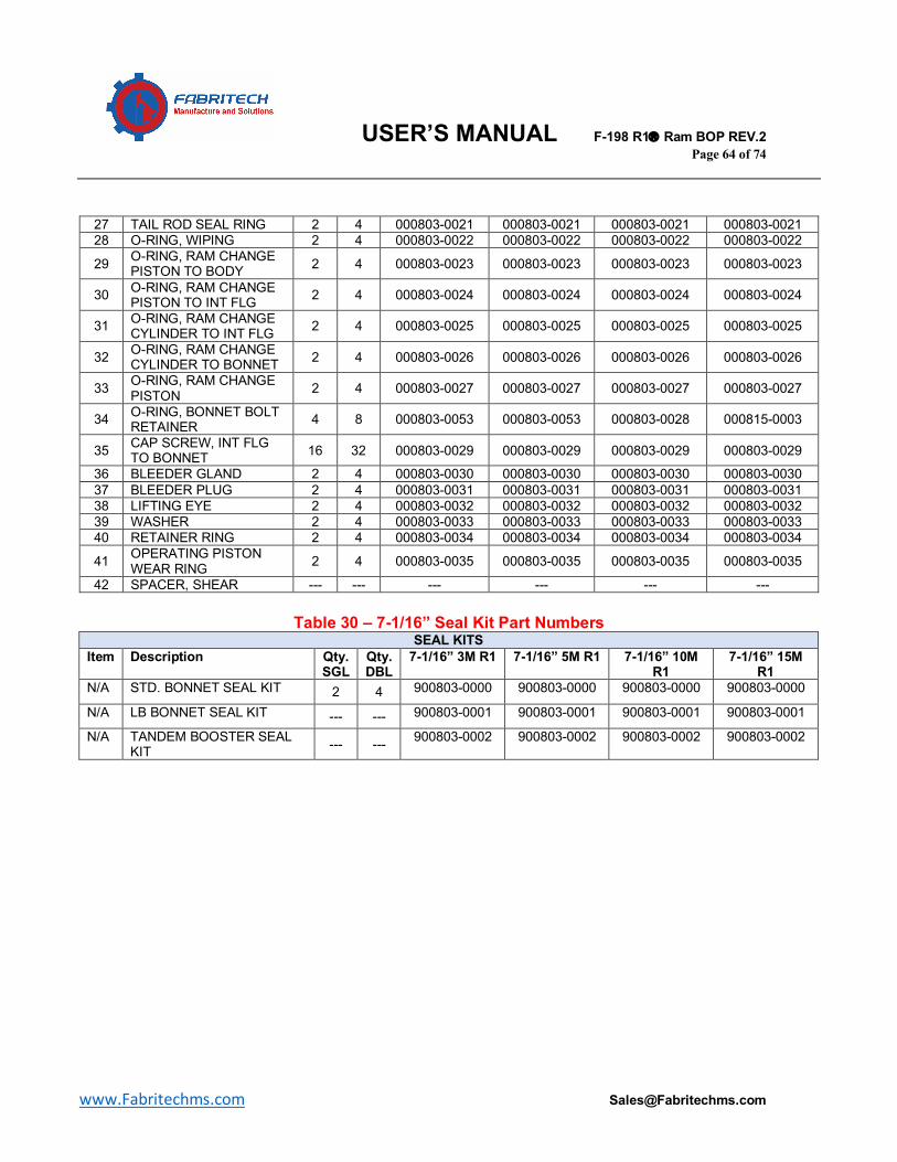
USER’S MANUAL F-198 R1â Ram BOP REV.2 Page 64 of 74
www.Fabritechms.com [email protected]
27 TAIL ROD SEAL RING 2 4 000803-0021 000803-0021 000803-0021 000803-0021 28 O-RING, WIPING 2 4 000803-0022 000803-0022 000803-0022 000803-0022 29 O-RING, RAM CHANGE
PISTON TO BODY 2 4 000803-0023 000803-0023 000803-0023 000803-0023
30 O-RING, RAM CHANGE PISTON TO INT FLG 2 4 000803-0024 000803-0024 000803-0024 000803-0024
31 O-RING, RAM CHANGE CYLINDER TO INT FLG 2 4 000803-0025 000803-0025 000803-0025 000803-0025
32 O-RING, RAM CHANGE CYLINDER TO BONNET 2 4 000803-0026 000803-0026 000803-0026 000803-0026
33 O-RING, RAM CHANGE PISTON 2 4 000803-0027 000803-0027 000803-0027 000803-0027
34 O-RING, BONNET BOLT RETAINER 4 8 000803-0053 000803-0053 000803-0028 000815-0003
35 CAP SCREW, INT FLG TO BONNET 16 32 000803-0029 000803-0029 000803-0029 000803-0029
36 BLEEDER GLAND 2 4 000803-0030 000803-0030 000803-0030 000803-0030 37 BLEEDER PLUG 2 4 000803-0031 000803-0031 000803-0031 000803-0031 38 LIFTING EYE 2 4 000803-0032 000803-0032 000803-0032 000803-0032 39 WASHER 2 4 000803-0033 000803-0033 000803-0033 000803-0033 40 RETAINER RING 2 4 000803-0034 000803-0034 000803-0034 000803-0034 41 OPERATING PISTON
WEAR RING 2 4 000803-0035 000803-0035 000803-0035 000803-0035 42 SPACER, SHEAR --- --- --- --- --- ---
Table 30 – 7-1/16” Seal Kit Part Numbers
SEAL KITS Item Description Qty.
SGL Qty. DBL
7-1/16” 3M R1 7-1/16” 5M R1 7-1/16” 10M R1
7-1/16” 15M R1
N/A STD. BONNET SEAL KIT 2 4 900803-0000 900803-0000 900803-0000 900803-0000 N/A LB BONNET SEAL KIT --- --- 900803-0001 900803-0001 900803-0001 900803-0001 N/A TANDEM BOOSTER SEAL
KIT --- --- 900803-0002 900803-0002 900803-0002 900803-0002
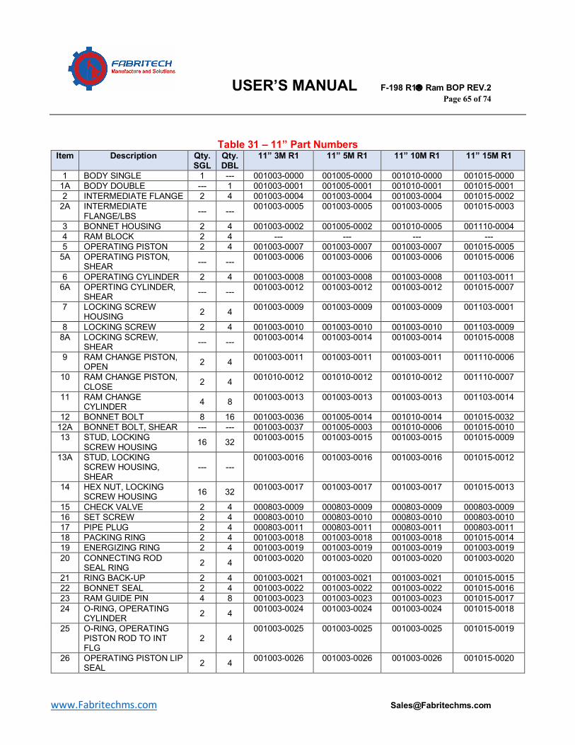
USER’S MANUAL F-198 R1â Ram BOP REV.2 Page 65 of 74
www.Fabritechms.com [email protected]
Table 31 – 11” Part Numbers Item Description Qty.
SGL Qty. DBL
11” 3M R1 11” 5M R1 11” 10M R1 11” 15M R1
1 BODY SINGLE 1 --- 001003-0000 001005-0000 001010-0000 001015-0000 1A BODY DOUBLE --- 1 001003-0001 001005-0001 001010-0001 001015-0001 2 INTERMEDIATE FLANGE 2 4 001003-0004 001003-0004 001003-0004 001015-0002
2A INTERMEDIATE FLANGE/LBS --- --- 001003-0005 001003-0005 001003-0005 001015-0003
3 BONNET HOUSING 2 4 001003-0002 001005-0002 001010-0005 001110-0004 4 RAM BLOCK 2 4 --- --- --- --- 5 OPERATING PISTON 2 4 001003-0007 001003-0007 001003-0007 001015-0005
5A OPERATING PISTON, SHEAR --- --- 001003-0006 001003-0006 001003-0006 001015-0006
6 OPERATING CYLINDER 2 4 001003-0008 001003-0008 001003-0008 001103-0011 6A OPERTING CYLINDER,
SHEAR --- --- 001003-0012 001003-0012 001003-0012 001015-0007
7 LOCKING SCREW HOUSING 2 4 001003-0009 001003-0009 001003-0009 001103-0001
8 LOCKING SCREW 2 4 001003-0010 001003-0010 001003-0010 001103-0009 8A LOCKING SCREW,
SHEAR --- --- 001003-0014 001003-0014 001003-0014 001015-0008
9 RAM CHANGE PISTON, OPEN 2 4 001003-0011 001003-0011 001003-0011 001110-0006
10 RAM CHANGE PISTON, CLOSE 2 4 001010-0012 001010-0012 001010-0012 001110-0007
11 RAM CHANGE CYLINDER 4 8 001003-0013 001003-0013 001003-0013 001103-0014
12 BONNET BOLT 8 16 001003-0036 001005-0014 001010-0014 001015-0032 12A BONNET BOLT, SHEAR --- --- 001003-0037 001005-0003 001010-0006 001015-0010 13 STUD, LOCKING
SCREW HOUSING 16 32 001003-0015 001003-0015 001003-0015 001015-0009
13A STUD, LOCKING SCREW HOUSING, SHEAR
--- --- 001003-0016 001003-0016 001003-0016 001015-0012
14 HEX NUT, LOCKING SCREW HOUSING 16 32 001003-0017 001003-0017 001003-0017 001015-0013
15 CHECK VALVE 2 4 000803-0009 000803-0009 000803-0009 000803-0009 16 SET SCREW 2 4 000803-0010 000803-0010 000803-0010 000803-0010 17 PIPE PLUG 2 4 000803-0011 000803-0011 000803-0011 000803-0011 18 PACKING RING 2 4 001003-0018 001003-0018 001003-0018 001015-0014 19 ENERGIZING RING 2 4 001003-0019 001003-0019 001003-0019 001003-0019 20 CONNECTING ROD
SEAL RING 2 4 001003-0020 001003-0020 001003-0020 001003-0020
21 RING BACK-UP 2 4 001003-0021 001003-0021 001003-0021 001015-0015 22 BONNET SEAL 2 4 001003-0022 001003-0022 001003-0022 001015-0016 23 RAM GUIDE PIN 4 8 001003-0023 001003-0023 001003-0023 001015-0017 24 O-RING, OPERATING
CYLINDER 2 4 001003-0024 001003-0024 001003-0024 001015-0018
25 O-RING, OPERATING PISTON ROD TO INT FLG
2 4 001003-0025 001003-0025 001003-0025 001015-0019
26 OPERATING PISTON LIP SEAL 2 4 001003-0026 001003-0026 001003-0026 001015-0020
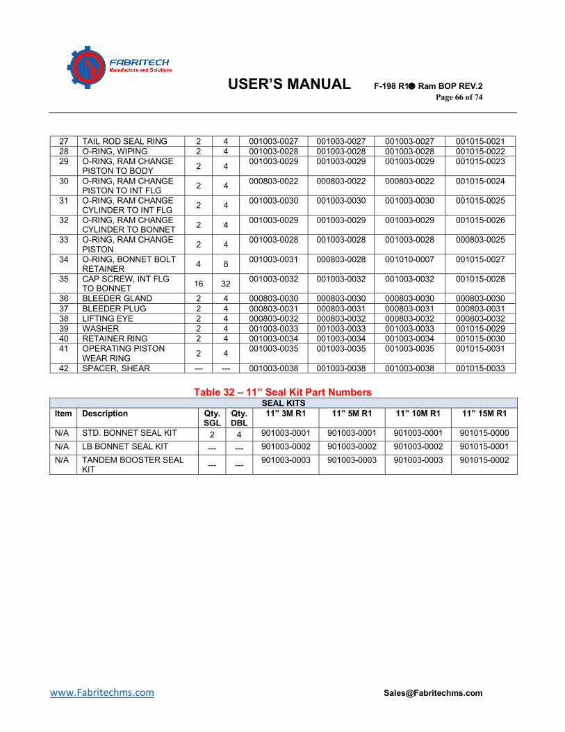
USER’S MANUAL F-198 R1â Ram BOP REV.2 Page 66 of 74
www.Fabritechms.com [email protected]
27 TAIL ROD SEAL RING 2 4 001003-0027 001003-0027 001003-0027 001015-0021 28 O-RING, WIPING 2 4 001003-0028 001003-0028 001003-0028 001015-0022 29 O-RING, RAM CHANGE
PISTON TO BODY 2 4 001003-0029 001003-0029 001003-0029 001015-0023
30 O-RING, RAM CHANGE PISTON TO INT FLG 2 4 000803-0022 000803-0022 000803-0022 001015-0024
31 O-RING, RAM CHANGE CYLINDER TO INT FLG 2 4 001003-0030 001003-0030 001003-0030 001015-0025
32 O-RING, RAM CHANGE CYLINDER TO BONNET 2 4 001003-0029 001003-0029 001003-0029 001015-0026
33 O-RING, RAM CHANGE PISTON 2 4 001003-0028 001003-0028 001003-0028 000803-0025
34 O-RING, BONNET BOLT RETAINER 4 8 001003-0031 000803-0028 001010-0007 001015-0027
35 CAP SCREW, INT FLG TO BONNET 16 32 001003-0032 001003-0032 001003-0032 001015-0028
36 BLEEDER GLAND 2 4 000803-0030 000803-0030 000803-0030 000803-0030 37 BLEEDER PLUG 2 4 000803-0031 000803-0031 000803-0031 000803-0031 38 LIFTING EYE 2 4 000803-0032 000803-0032 000803-0032 000803-0032 39 WASHER 2 4 001003-0033 001003-0033 001003-0033 001015-0029 40 RETAINER RING 2 4 001003-0034 001003-0034 001003-0034 001015-0030 41 OPERATING PISTON
WEAR RING 2 4 001003-0035 001003-0035 001003-0035 001015-0031
42 SPACER, SHEAR --- --- 001003-0038 001003-0038 001003-0038 001015-0033
Table 32 – 11” Seal Kit Part Numbers SEAL KITS
Item Description Qty. SGL
Qty. DBL
11” 3M R1 11” 5M R1 11” 10M R1 11” 15M R1
N/A STD. BONNET SEAL KIT 2 4 901003-0001 901003-0001 901003-0001 901015-0000 N/A LB BONNET SEAL KIT --- --- 901003-0002 901003-0002 901003-0002 901015-0001 N/A TANDEM BOOSTER SEAL
KIT --- --- 901003-0003 901003-0003 901003-0003 901015-0002
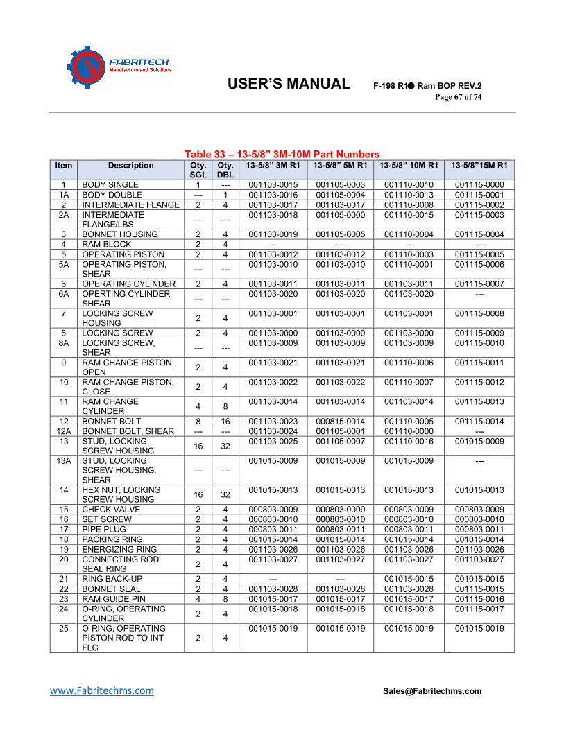
USER’S MANUAL F-198 R1â Ram BOP REV.2 Page 67 of 74
www.Fabritechms.com [email protected]
Table 33 – 13-5/8” 3M-10M Part Numbers
Item Description Qty. SGL
Qty. DBL
13-5/8” 3M R1 13-5/8” 5M R1 13-5/8” 10M R1 13-5/8”15M R1
1 BODY SINGLE 1 --- 001103-0015 001105-0003 001110-0010 001115-0000 1A BODY DOUBLE --- 1 001103-0016 001105-0004 001110-0013 001115-0001 2 INTERMEDIATE FLANGE 2 4 001103-0017 001103-0017 001110-0008 001115-0002
2A INTERMEDIATE FLANGE/LBS --- --- 001103-0018 001105-0000 001110-0015 001115-0003
3 BONNET HOUSING 2 4 001103-0019 001105-0005 001110-0004 001115-0004 4 RAM BLOCK 2 4 --- --- --- --- 5 OPERATING PISTON 2 4 001103-0012 001103-0012 001110-0003 001115-0005
5A OPERATING PISTON, SHEAR --- --- 001103-0010 001103-0010 001110-0001 001115-0006
6 OPERATING CYLINDER 2 4 001103-0011 001103-0011 001103-0011 001115-0007 6A OPERTING CYLINDER,
SHEAR --- --- 001103-0020 001103-0020 001103-0020 ---
7 LOCKING SCREW HOUSING 2 4 001103-0001 001103-0001 001103-0001 001115-0008
8 LOCKING SCREW 2 4 001103-0000 001103-0000 001103-0000 001115-0009 8A LOCKING SCREW,
SHEAR --- --- 001103-0009 001103-0009 001103-0009 001115-0010
9 RAM CHANGE PISTON, OPEN 2 4 001103-0021 001103-0021 001110-0006 001115-0011
10 RAM CHANGE PISTON, CLOSE 2 4 001103-0022 001103-0022 001110-0007 001115-0012
11 RAM CHANGE CYLINDER 4 8 001103-0014 001103-0014 001103-0014 001115-0013
12 BONNET BOLT 8 16 001103-0023 000815-0014 001110-0005 001115-0014 12A BONNET BOLT, SHEAR --- --- 001103-0024 001105-0001 001110-0000 --- 13 STUD, LOCKING
SCREW HOUSING 16 32 001103-0025 001105-0007 001110-0016 001015-0009
13A STUD, LOCKING SCREW HOUSING, SHEAR
--- --- 001015-0009 001015-0009 001015-0009 ---
14 HEX NUT, LOCKING SCREW HOUSING 16 32 001015-0013 001015-0013 001015-0013 001015-0013
15 CHECK VALVE 2 4 000803-0009 000803-0009 000803-0009 000803-0009 16 SET SCREW 2 4 000803-0010 000803-0010 000803-0010 000803-0010 17 PIPE PLUG 2 4 000803-0011 000803-0011 000803-0011 000803-0011 18 PACKING RING 2 4 001015-0014 001015-0014 001015-0014 001015-0014 19 ENERGIZING RING 2 4 001103-0026 001103-0026 001103-0026 001103-0026 20 CONNECTING ROD
SEAL RING 2 4 001103-0027 001103-0027 001103-0027 001103-0027
21 RING BACK-UP 2 4 --- --- 001015-0015 001015-0015 22 BONNET SEAL 2 4 001103-0028 001103-0028 001103-0028 001115-0015 23 RAM GUIDE PIN 4 8 001015-0017 001015-0017 001015-0017 001115-0016 24 O-RING, OPERATING
CYLINDER 2 4 001015-0018 001015-0018 001015-0018 001115-0017
25 O-RING, OPERATING PISTON ROD TO INT FLG
2 4 001015-0019 001015-0019 001015-0019 001015-0019
USER’S MANUAL F-198 R1â Ram BOP REV.2 Page 68 of 74
www.Fabritechms.com [email protected]
26 OPERATING PISTON LIP SEAL 2 4 001015-0020 001015-0020 001015-0020 001115-0018
27 TAIL ROD SEAL RING 2 4 001015-0021 001015-0021 001015-0021 001115-0019 28 O-RING, WIPING 2 4 001015-0022 001015-0022 001015-0022 001115-0020 29 O-RING, RAM CHANGE
PISTON TO BODY 2 4 001015-0023 001015-0023 001015-0023 001115-0021
30 O-RING, RAM CHANGE PISTON TO INT FLG 2 4 001015-0024 001015-0024 001015-0024 001115-0022
31 O-RING, RAM CHANGE CYLINDER TO INT FLG 2 4 001015-0025 001015-0025 001015-0025 001115-0023
32 O-RING, RAM CHANGE CYLINDER TO BONNET 2 4 001015-0026 001015-0026 001015-0026 001115-0024
33 O-RING, RAM CHANGE PISTON 2 4 000803-0025 000803-0025 000803-0025 001115-0025
34 O-RING, BONNET BOLT RETAINER 4 8 001103-0029 000815-0003 001015-0027 001115-0026
35 CAP SCREW, INT FLG TO BONNET 16 32 001103-0030 001105-0009 001015-0028 001115-0027
36 BLEEDER GLAND 2 4 000803-0030 000803-0030 000803-0030 000803-0030 37 BLEEDER PLUG 2 4 000803-0031 000803-0031 000803-0031 000803-0031 38 LIFTING EYE 2 4 000803-0032 000803-0032 000803-0032 000803-0032 39 WASHER 2 4 001015-0029 001015-0029 001015-0029 001015-0029 40 RETAINER RING 2 4 001015-0030 001015-0030 001015-0030 001015-0030 41 OPERATING PISTON
WEAR RING 2 4 001015-0031 001015-0031 001015-0031 001115-0028
42 SPACER, SHEAR --- --- 001015-0033 001015-0033 001015-0033 001115-0029
Table 34 – 13-5/8” 3-10M Seal Kit Part Numbers SEAL KITS
Item Description Qty. SGL
Qty. DBL
13-5/8” 3M R1 13-5/8” 5M R1 13-5/8” 10M R1
13-5/8”15M R1
N/A STD. BONNET SEAL KIT 2 4 901103-0000 901103-0000 901103-0000 901115-0002 N/A LB BONNET SEAL KIT --- --- 901103-0001 901103-0001 901103-0001 901115-0003 N/A TANDEM BOOSTER SEAL
KIT --- --- 901103-0002 901103-0002 901103-0002 901115-0004
USER’S MANUAL F-198 R1â Ram BOP REV.2 Page 69 of 74
www.Fabritechms.com [email protected]
Table 35 – 16-3/4” 3-10M & 18-3/4” 10M Part Numbers
Item Description Qty. SGL
Qty. DBL
16-3/4” 3M R1 16-3/4” 5M R1 16-3/4” 10M R1 18-3/4”10M R1
1 BODY SINGLE 1 --- 001203-0000 001205-0000 001210-0000 001310-0000 1A BODY DOUBLE --- 1 001203-0001 001205-0001 001210-0001 001310-0001 2 INTERMEDIATE FLANGE 2 4 001203-0002 001205-0002 001210-0002 001310-0002
2A INTERMEDIATE FLANGE/LBS --- --- --- 001205-0003 --- ---
3 BONNET HOUSING 2 4 001203-0003 001205-0004 001115-0004 001310-0003 4 RAM BLOCK 2 4 --- --- --- --- 5 OPERATING PISTON 2 4 001203-0004 001205-0005 001210-0003 001310-0004
5A OPERATING PISTON, SHEAR --- --- --- 001205-0006 001210-0004 ---
6 OPERATING CYLINDER 2 4 001115-0007 001115-0007 001205-0007 001310-0005 6A OPERTING CYLINDER,
SHEAR --- --- --- 001205-0007 --- ---
7 LOCKING SCREW HOUSING 2 4 001115-0008 001115-0008 001115-0008 001310-0006
8 LOCKING SCREW 2 4 001203-0005 001203-0005 001115-0009 001310-0007 8A LOCKING SCREW,
SHEAR --- --- --- 001115-0009 --- ---
9 RAM CHANGE PISTON, OPEN 2 4 001203-0006 001115-0011 001210-0005 001310-0008
10 RAM CHANGE PISTON, CLOSE 2 4 001203-0007 001115-0012 001210-0006 001310-0009
11 RAM CHANGE CYLINDER 4 8 001203-0008 001115-0013 001210-0007 001310-0010
12 BONNET BOLT 8 16 001203-0009 001205-0008 001210-0008 001310-0014 12A BONNET BOLT, SHEAR --- --- --- 001205-0009 --- --- 13 STUD, LOCKING
SCREW HOUSING 16 32 001203-0010 001205-0010 001210-0009 001310-0015
13A STUD, LOCKING SCREW HOUSING, SHEAR
--- --- --- 001205-0011 --- ---
14 HEX NUT, LOCKING SCREW HOUSING 16 32 001015-0013 001015-0013 001015-0013 001310-0016
15 CHECK VALVE 2 4 000803-0009 000803-0009 000803-0009 000803-0009 16 SET SCREW 2 4 000803-0010 000803-0010 000803-0010 000803-0010 17 PIPE PLUG 2 4 000803-0011 000803-0011 000803-0011 000803-0011 18 PACKING RING 2 4 001203-0011 001203-0011 001203-0011 001310-0017 19 ENERGIZING RING 2 4 001203-0012 001203-0012 001203-0012 001310-0018 20 CONNECTING ROD
SEAL RING 2 4 001203-0013 001203-0013 001203-0013 001310-0019
21 RING BACK-UP 2 4 --- --- 001210-0010 001310-0020 22 BONNET SEAL 2 4 001203-0014 001203-0014 001203-0014 001310-0021 23 RAM GUIDE PIN 4 8 001203-0015 001203-0015 001203-0015 001310-0022 24 O-RING, OPERATING
CYLINDER 2 4 001115-0017 001115-0017 001115-0017 001310-0035
25 O-RING, OPERATING PISTON ROD TO INT FLG
2 4 001203-0016 001203-0016 001203-0016 001310-0023
USER’S MANUAL F-198 R1â Ram BOP REV.2 Page 70 of 74
www.Fabritechms.com [email protected]
26 OPERATING PISTON LIP SEAL 2 4 001115-0018 001115-0018 001115-0018 001310-0024
27 TAIL ROD SEAL RING 2 4 001115-0019 001115-0019 001115-0019 001103-0027 28 O-RING, WIPING 2 4 001115-0020 001115-0020 001115-0020 001310-0025 29 O-RING, RAM CHANGE
PISTON TO BODY 2 4 001115-0021 001115-0021 001115-0021 001310-0026
30 O-RING, RAM CHANGE PISTON TO INT FLG 2 4 001115-0022 001115-0022 001115-0022 001003-0029
31 O-RING, RAM CHANGE CYLINDER TO INT FLG 2 4 001115-0023 001115-0023 001115-0023 001310-0027
32 O-RING, RAM CHANGE CYLINDER TO BONNET 2 4 001115-0024 001115-0024 001115-0024 001310-0028
33 O-RING, RAM CHANGE PISTON 2 4 001115-0025 001115-0025 001115-0025 001310-0029
34 O-RING, BONNET BOLT RETAINER 4 8 000815-0003 001205-0012 001115-0026 001310-0030
35 CAP SCREW, INT FLG TO BONNET 16 32 001203-0017 001115-0027 001210-0011 001310-0031
36 BLEEDER GLAND 2 4 000803-0030 000803-0030 000803-0030 000803-0030 37 BLEEDER PLUG 2 4 000803-0031 000803-0031 000803-0031 000803-0031 38 LIFTING EYE 2 4 000803-0032 000803-0032 000803-0032 000803-0032 39 WASHER 2 4 001203-0018 001203-0018 001203-0018 001310-0032 40 RETAINER RING 2 4 001203-0019 001203-0019 001210-0012 001310-0033 41 OPERATING PISTON
WEAR RING 2 4 001115-0028 001115-0028 001115-0028 001310-0034
42 SPACER, SHEAR --- --- --- 001115-0029 001115-0029 ---
Table 36 – 16-3/4” 3-10M & 18-3/4” 10M Seal Kit Part Numbers SEAL KITS
Item Description Qty. SGL
Qty. DBL
16-3/4” 3M R1 16-3/4” 5M R1 16-3/4” 10M R1
18-3/4”10M R1
N/A STD. BONNET SEAL KIT 2 4 901203-0000 901203-0000 901203-0000 901310-0000 N/A LB BONNET SEAL KIT --- --- --- 901203-0001 901203-0001 901310-0001 N/A TANDEM BOOSTER SEAL
KIT --- --- --- 901205-0002 901205-0002 ---
USER’S MANUAL F-198 R1â Ram BOP REV.2 Page 71 of 74
www.Fabritechms.com [email protected]
Table 37 – 20-3/4” 3M, 21-1/4” 2-10M Part Numbers Item Description Qty.
SGL Qty. DBL
20-3/4” 3M R1 21-1/4” 2M R1 21-1/4” 5M R1 21-1/4”10M R1
1 BODY SINGLE 1 --- 001403-0000 001502-0000 001505-0000 001510-0000 1A BODY DOUBLE --- 1 001403-0001 001502-0001 001505-0001 001510-0001 2 INTERMEDIATE FLANGE 2 4 001403-0002 001502-0002 --- 001510-0002
2A INTERMEDIATE FLANGE/LBS
--- --- 001403-0003 001403-0003 001505-0003 001510-0003
3 BONNET HOUSING 2 4 001403-0004 001502-0004 001505-0004 001510-0004 4 RAM BLOCK 2 4 --- --- --- --- 5 OPERATING PISTON 2 4 001403-0005 001502-0005 001505-0005 001510-0005
5A OPERATING PISTON, SHEAR
--- --- 001403-0006 001403-0006 --- 001510-0006
6 OPERATING CYLINDER 2 4 001403-0007 001403-0007 001505-0007 001505-0007 6A OPERTING CYLINDER,
SHEAR --- --- 001403-0008 001403-0008 --- 001510-0008
7 LOCKING SCREW HOUSING
2 4 001403-0009 001403-0009 001505-0008 001505-0008
8 LOCKING SCREW 2 4 001103-0009 001103-0009 001310-0007 001310-0007 8A LOCKING SCREW,
SHEAR --- --- 001403-0010 001403-0010 --- ---
9 RAM CHANGE PISTON, OPEN
2 4 001403-0011 001403-0011 001505-0011 001505-0011
10 RAM CHANGE PISTON, CLOSE
2 4 001403-0012 001403-0012 001505-0012 001505-0012
11 RAM CHANGE CYLINDER
4 8 001403-0013 001403-0013 001505-0013 001505-0013
12 BONNET BOLT 8 16 001403-0014 001502-0014 001505-0014 001510-0014 12A BONNET BOLT, SHEAR --- --- 001403-0015 001502-0015 --- 001510-0009 13 STUD, LOCKING
SCREW HOUSING 16 32 001210-0009 001210-0009 001310-0015 001310-0015
13A STUD, LOCKING SCREW HOUSING, SHEAR
--- --- 001015-0009 001015-0009 --- ---
14 HEX NUT, LOCKING SCREW HOUSING
16 32 001015-0013 001015-0013 001310-0016 001310-0016
15 CHECK VALVE 2 4 000803-0009 000803-0009 000803-0009 000803-0009 16 SET SCREW 2 4 000803-0010 000803-0010 000803-0010 000803-0010 17 PIPE PLUG 2 4 000803-0011 000803-0011 000803-0011 000803-0011 18 PACKING RING 2 4 001015-0014 001015-0014 001505-0015 001505-0015 19 ENERGIZING RING 2 4 001103-0026 001103-0026 001505-0016 001505-0016 20 CONNECTING ROD
SEAL RING 2 4 001103-0027 001103-0027 001505-0017 001505-0017
21 RING BACK-UP 2 4 --- --- 001505-0018 001505-0018 22 BONNET SEAL 2 4 001403-0016 001403-0016 001505-0019 001505-0019 23 RAM GUIDE PIN 4 8 001403-0017 001403-0017 001310-0022 001310-0022 24 O-RING, OPERATING
CYLINDER 2 4 001015-0018 001015-0018 001310-0035 001310-0035
25 O-RING, OPERATING PISTON ROD TO INT FLG
2 4 001015-0019 001015-0019 001505-0020 001505-0020
26 OPERATING PISTON LIP SEAL
2 4 001015-0020 001015-0020 001505-0021 001505-0021
USER’S MANUAL F-198 R1â Ram BOP REV.2 Page 72 of 74
www.Fabritechms.com [email protected]
27 TAIL ROD SEAL RING 2 4 001015-0021 001015-0021 001103-0027 001103-0027 28 O-RING, WIPING 2 4 001015-0022 001015-0022 001310-0025 001310-0025 29 O-RING, RAM CHANGE
PISTON TO BODY 2 4 001403-0018 001403-0018 001505-0022 001505-0022
30 O-RING, RAM CHANGE PISTON TO INT FLG
2 4 001403-0019 001403-0019 001505-0023 001505-0023
31 O-RING, RAM CHANGE CYLINDER TO INT FLG
2 4 001403-0020 001403-0020 001505-0024 001505-0024
32 O-RING, RAM CHANGE CYLINDER TO BONNET
2 4 001403-0021 001403-0021 001505-0025 001505-0025
33 O-RING, RAM CHANGE PISTON
2 4 001015-0026 001015-0026 001505-0026 001505-0026
34 O-RING, BONNET BOLT RETAINER
4 8 000803-0028 001003-0031 001310-0030 001510-0010
35 CAP SCREW, INT FLG TO BONNET
16 32 001403-0022 001403-0022 001505-0027 001505-0027
36 BLEEDER GLAND 2 4 000803-0030 000803-0030 000803-0030 000803-0030 37 BLEEDER PLUG 2 4 000803-0031 000803-0031 000803-0031 000803-0031 38 LIFTING EYE 2 4 000803-0032 000803-0032 000803-0032 000803-0032 39 WASHER 2 4 001015-0029 001015-0029 001505-0028 001505-0028 40 RETAINER RING 2 4 001015-0030 001015-0030 001505-0029 001505-0029 41 OPERATING PISTON
WEAR RING 2 4 001403-0023 001403-0023 001505-0030 001510-0011
42 SPACER, SHEAR --- --- 001015-0033 001015-0033 --- ---
USER’S MANUAL F-198 R1â Ram BOP REV.2 Page 73 of 74
www.Fabritechms.com [email protected]
Table 38– 26-3/4” 3M Part Numbers Item Description Qty. SGL Qty. DBL 26-3/4” 3M R1
1 BODY SINGLE 1 --- 001603-0000 1A BODY DOUBLE --- 1 001603-0001 2 INTERMEDIATE FLANGE 2 4 ---
2A INTERMEDIATE FLANGE/LBS --- --- 001603-0003 3 BONNET HOUSING 2 4 001603-0004 4 RAM BLOCK 2 4 --- 5 OPERATING PISTON 2 4 001603-0005
5A OPERATING PISTON, SHEAR --- --- --- 6 OPERATING CYLINDER 2 4 001603-0007
6A OPERTING CYLINDER, SHEAR --- --- --- 7 LOCKING SCREW HOUSING 2 4 001603-0008 8 LOCKING SCREW 2 4 001403-0010
8A LOCKING SCREW, SHEAR --- --- --- 9 RAM CHANGE PISTON, OPEN 2 4 001603-0009
10 RAM CHANGE PISTON, CLOSE 2 4 001603-0010 11 RAM CHANGE CYLINDER 4 8 001603-0011 12 BONNET BOLT 8 16 001603-0014
12A BONNET BOLT, SHEAR --- --- --- 13 STUD, LOCKING SCREW HOUSING 16 32 001210-0009
13A STUD, LOCKING SCREW HOUSING, SHEAR --- --- --- 14 HEX NUT, LOCKING SCREW HOUSING 16 32 001015-0013 15 CHECK VALVE 2 4 000803-0009 16 SET SCREW 2 4 000803-0010 17 PIPE PLUG 2 4 000803-0011 18 PACKING RING 2 4 001015-0014 19 ENERGIZING RING 2 4 001103-0026 20 CONNECTING ROD SEAL RING 2 4 001103-0027 21 RING BACK-UP 2 4 --- 22 BONNET SEAL 2 4 001603-0012 23 RAM GUIDE PIN 4 8 001603-0013 24 O-RING, OPERATING CYLINDER 2 4 001015-0018 25 O-RING, OPERATING PISTON ROD TO INT FLG 2 4 001015-0019 26 OPERATING PISTON LIP SEAL 2 4 001015-0020 27 TAIL ROD SEAL RING 2 4 001015-0021 28 O-RING, WIPING 2 4 001015-0022 29 O-RING, RAM CHANGE PISTON TO BODY 2 4 001115-0025 30 O-RING, RAM CHANGE PISTON TO INT FLG 2 4 001603-0015 31 O-RING, RAM CHANGE CYLINDER TO INT FLG 2 4 001403-0021 32 O-RING, RAM CHANGE CYLINDER TO BONNET 2 4 001603-0016 33 O-RING, RAM CHANGE PISTON 2 4 001603-0017 34 O-RING, BONNET BOLT RETAINER 4 8 001015-0027 35 CAP SCREW, INT FLG TO BONNET 16 32 001603-0018 36 BLEEDER GLAND 2 4 000803-0030 37 BLEEDER PLUG 2 4 000803-0031 38 LIFTING EYE 2 4 000803-0032 39 WASHER 2 4 001015-0029 40 RETAINER RING 2 4 001015-0030
USER’S MANUAL F-198 R1â Ram BOP REV.2 Page 74 of 74
www.Fabritechms.com [email protected]
41 OPERATING PISTON WEAR RING 2 4 001403-0023 42 SPACER, SHEAR --- --- ---
Table 39– 20-3/4” 3M, 21-1/4” 2-10M, & 26-3/4” 5M Seal Kit Part Numbers SEAL KITS
Item Description Qty. SGL
Qty. DBL
20-3/4” 3M R1
21-1/4” 2M R1
21-1/4” 5M R1
21-1/4”10M R1
26-3/4” 3M R1
N/A STD. BONNET SEAL KIT 2 4 901403-0000
901403-0000
901505-0002
901510-0001
901603-0000
N/A LB BONNET SEAL KIT --- --- 901403-0001
901403-0001
901505-0003
901510-0002
---
N/A TANDEM BOOSTER SEAL KIT --- --- 901403-
0002 901403-0002
901505-0004
901510-0003
---