cable handling equipment brochure - thomson rail and pages/cable handling brochure.pdf · 2...
TRANSCRIPT

Copyright: Th omson Engineering Design Ltd 2013 all rights reservedDocument Number: CE-013-01 Issue: 01 Date: March 2013
Thomson Engineering Design LtdCable Handling Equipment
A Technical Guide to the Range of Cable Handling Equipment Available 2013 and an overview of our
bespoke product development capability

2
Introduction
Th omson Engineering Design Ltd has been designing, refurbishing and manufacturing cable handling equipment since 2004. Th is document gives technical details of the existing equipment range and a short introduction to our bespoke design and build service.
Our range of equipment goes from the simple cable thimble - used for threading and manipulating cables - to bespoke cable pulling machines capable of dragging and installing cables up to 60 tonnes in weight.
All our equipment is designed and built at our factory in the West of England and all our processes and procedures are covered by ISO 9001 certifi cation including our in-house CE marking system.
More than 60% of our business involves the design and construction of bespoke equipment for industry and we are proud of our customer base which includes most of the key players in the rail and plant hire industries.

3
Part 1: Established Cable Handling Products
On the following pages you will fi nd details of products already proven within industry for the handling, storage and laying of cables.
All of these may be modifi ed to suit special requirements and we will be pleased to discuss this in more detail.

4
Trailer Based Drum Carrier
The Thomson Cable Drum Carrier is designed for use on rail trailers
to provide a high strength, low rolling resistance support for cable drums up to 8,000 kg .
The special adapter cones, which can be used with drum sha holes from 90mm to 200mm, sit on ball bearing rollers making it excep onally easy to load and unload drums.
Because of the low rolling resistance of this arrangement our Drum Carrier is frequently specifi ed for delicate cables such as fi bre op cs.
Specifi cations given may be subject to change due to our policy of continuous improvement
Specifications
Weight (Complete with shaft) 480 kgShaft Diameter 80 mmDrum shaft hole 90 mm to 200 mmWLL (Safe Working Load) 8,000 kgProof Load (Factory test) 12,000 kgMechanism Low Resistance Roller
Features
• Simple to load and unload• Adaptable to a wide range of drum sizes• Braked and powered versions available • Very low rolling resistance for delicate
cables• Full Factory Parts Backup• CE Marked
A VERSATILE AND EASY TO USE CABLE DRUM STAND FOR TRAILER AND WAGON APPLICATIONS
Benefits
Low rolling resistance
8,000kg capacity
Wide range of drum sizes
Colour 08E51 Yellow
Documentation
Operator’s / Maintenance ManualLOLER Test Certificate

5
Technical Details
Th is product is designed to be mounted on an RRV trailer. Up to 3 units may be placed on a standard 6m trailer.
Th e base frame, which is lashed down on to the trailer deck, supports a carriage frame. Th e carriage frame can be rotated on the centre point of the base frame so that the drum shaft can be angled up to 35 degrees in either direction.
Two drum support frames are mounted on the carriage frame. Th ese can be rolled across the carriage frame to adjust for diff erent drum widths and to allow the drum to be off set to either side of the trailer.
Th e upper part of the drum support frames can be raised and lowered to cope with the largest drums. Integrated into this section are two rollers mounted on sealed ball bearings. Th ese rollers are used to support the drum shaft and give it a very low friction rolling function.
Cable drums are pre-fi tted into the drum shaft and secured with specially designed grooved cones. Using a lift ing beam which can also be supplied by Th omson Engineering Design the shaft is lift ed into the drum supports and placed so that the groove in each cone is placed on the rollers.
A simple cross pin is then inserted above the grooved cones to secure the drum and shaft for transport.
Accessories supplied for this device include:
• Sha braking
• Drum braking
• Powered drum drive system
• Drum li ing beam
For further details please contact Th omson Engineering Design Ltd on 01594 82 66 11

6
Cable Thimbles
Thomson Cable Thimbles are designed to be suspended from
the lifting hook of an excavator crane to guide the cable off the drum.
A so polyurethane roller running on low fric on bearings ensures that the cable is carefully handled.
To disconnect the thimble without cu ng the cable the roller can be easily removed from the frame.
Single, twin and mul ple roller versions are available to order.
Specifi cations given may be subject to change due to our policy of continuous improvement
Specifications
Weight (Single) 11 kgWeight (Twin) 14 kgWLL (Safe Working Load /cable) 30 kgProof Load (Factory test) 45 kg
Features
• Strong and Light• Designed to protect cable• Soft urethane rollers• 45kg Proof Load• Full Factory Parts Backup• CE Marked
A SIMPLE WAY TO REDUCE THE HARD WORK OF CABLE INSTALLATION
Benefits
Fully certifi cated and tested.
Simple to use.
Light weight.
Low rolling resistance.
Signal HeadsJunction IndicatorsPost platform rails
Documentation
Operator’s / Maintenance ManualLOLER Test Certificate

7
Technical Details
Typically fi tted to the lift ing point on the boom of an RRV, our cable thimbles are frequently used in conjunction with our trailer mounted drum carrier to help prevent the cable dragging on the ground.
Cable thimbles consist of a fabricated steel frame and polyurethane rollers. Th e rollers have oil impregnated bronze bushes running on a smooth steel shaft so that they turn easily.
Th is combination supports the cable and minimises the risk of damage to the cable outer sheath.
Th e shaft can be quickly and easily removed to allow the rollers to be removed to release the cable.
Single roller, twin roller and triple roller designs are available.

8
Cable Handling Trailer
The Thomson Cable Trailer is an ideal solution for laying cable in
restricted working locations such as tunnels.Manually operated hydraulic li arms mean that this trailer is totally self-contained.
The Cable Trailer can load itself with drums placed in the four-foot and it incorporates the same low rolling resistance drum sha supports as our other drum handlers making it ideal for delicate cables as well as heavy power lines.
Automa c, fail-safe brakes are fi ed as standard.
Specifi cations given may be subject to change due to our policy of continuous improvement
Specifications
Weight 1,900 kgBrakes Fail-safe on 2 wheelsShaft Size 80mm diam..Safe Working Load 3,000 kgProof Load (Factory test) 4,500 kg
Features
• Self Loading• Precision Height Control• Low Rolling Resistance Shaft• Powered and braked versions available• 3,000 kg WLL• 4,500 kg Proof Load• Full Factory Parts Backup• CE Marked
A FAST AND EASY WAY TO LAY CABLES IN RESTRICTED AREAS
Benefits
Precision drum control
Low rolling resistance for delicate cables
Fail-safe brakes
System Hyd.. Pressure 210 Bar
Body Colour 08E51 YellowMoving Parts Signal Red
Documentation
Operator’s ManualParts ManualMaintenance PlanLOLER Test Certificate

9
Technical Details
For single drums up to 3,000kg the Cable Handling Trailer provides a rapid handling and delivery solution.
Drums are lift ed into the four-foot by a crane and fi tted with the specially designed drum shaft . Th e trailer is then moved into position and the hand pump used to raise the arms, picking up the drum shaft in low rolling friction roller supports.
Th e trailer is then quickly towed to the work site and cable laying off can begin immediately.
Th ese units were built exclusively for use on the extension to London Underground lines into Terminal 5 at Heathrow where precise control of the drum height was required to avoid collision with temporary ventilation and power systems.
For use elsewhere Vehicle Acceptance would be required but this can be arranged during manufacture through our close association with Atkins Rail Vehicle Acceptance.
A wide range of accessories including lighting systems, powered drum and braked drum systems as well as a variety of service and parking braking systems can be specifi ed.

10
Cable Handling Yoke
The Thomson Cable Handling Yoke is the most effi cient way to
handle cable drums and to lay cable using an excavator crane.By withdrawing two retaining pins the drum sha is released from the Yoke.
Fit the drum sha to the cable drum and pick it up with the Yoke. Lock the retaining pins and you are ready to lay the cable.
The Yoke can even be fi ed with a hydraulic rotator to help posi on the drum when used just for drum handling. Can be made to suit any range of drum sizes and weights.
Specifi cations given may be subject to change due to our policy of continuous improvement
Specifications (std.)
Weight (typical) 145 kgShaft Diameter 80 mmMax drum width 1,200 mmSafe Working Load 3,000 kgProof Load (Factory test) 6,000 kg
Features
• Strong and Robust• Very quick and simple to use• All Steel Welded Construction• High Resistance to Dynamic Loads• High Resistance to Abuse• Versions for any range of drum sizes and
weights can be supplied• 6,000 kg Proof Load• Full Factory Parts Backup• CE Marked
A REALLY EASY TO USE AND QUICK SOLUTION TO CABLE LAYING
Benefits
Minimises handling time
Maximises productivity
High reliability through robust construction
Rotator VersionMax. Hyd.. Pressure 210 BarMin. Hyd.. Pressure 50 Bar
Body Colour 08E51 Yellow
Documentation
Operator’s ManualParts ManualMaintenance PlanLOLER Test Certificate

11
Technical Details
Using the Cable Yoke minimises handling time and gives the most effi cient solution to laying cable from drums up to 3,000kg.
Simply suspended from the lift ing point of a RRV or excavator crane the yoke is fi tted with the same low rolling friction cable shaft support used on our heavy duty trailer mounted drum carriers.
Th is device can also be mounted on a hydraulic rotator giving the machine operator complete control on the angle of the cable drum during laying off .
Th e Cable Handling Yoke can be built to any required size compatible with the lift ing capacity of the host crane.
12
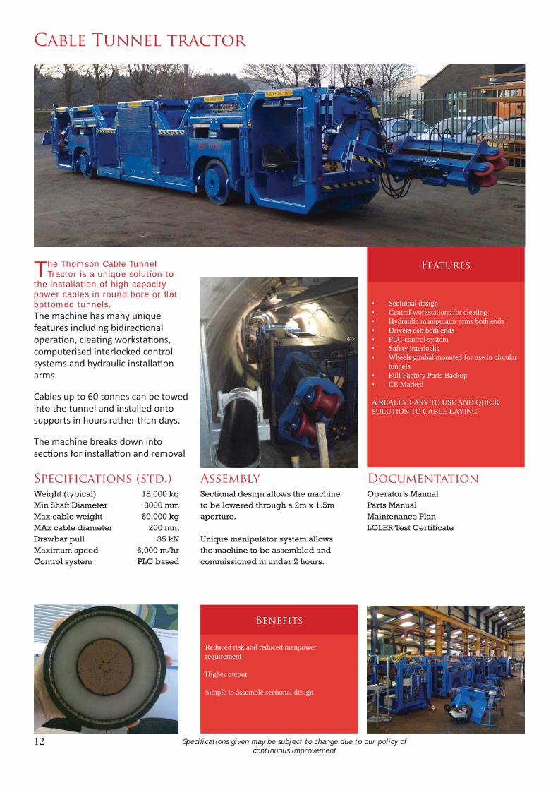
Cable Tunnel tractor
The Thomson Cable Tunnel Tractor is a unique solution to
the installation of high capacity power cables in round bore or fl at bottomed tunnels.The machine has many unique features including bidirec onal opera on, clea ng worksta ons, computerised interlocked control systems and hydraulic installa on arms.
Cables up to 60 tonnes can be towed into the tunnel and installed onto supports in hours rather than days.
The machine breaks down into sec ons for installa on and removal
Specifi cations given may be subject to change due to our policy of continuous improvement
Specifications (std.)
Weight (typical) 18,000 kgMin Shaft Diameter 3000 mmMax cable weight 60,000 kgMAx cable diameter 200 mmDrawbar pull 35 kNMaximum speed 6,000 m/hrControl system PLC based
Features
• Sectional design• Central workstations for cleating• Hydraulic manipulator arms both ends• Drivers cab both ends• PLC control system• Safety interlocks• Wheels gimbal mounted for use in circular
tunnels• Full Factory Parts Backup• CE Marked
A REALLY EASY TO USE AND QUICK SOLUTION TO CABLE LAYING
Benefits
Reduced risk and reduced manpower requirement
Higher output
Simple to assemble sectional design
Assembly
Sectional design allows the machine to be lowered through a 2m x 1.5m aperture.
Unique manipulator system allows the machine to be assembled and commissioned in under 2 hours.
Documentation
Operator’s ManualParts ManualMaintenance PlanLOLER Test Certificate

13
Technical Details
Heavy power cables have traditionally been installed by using winches to pull the cable into position and then manually lift ing them onto cable support brackets.
Th is is a slow and dangerous process which can be radically improved by the use of our cable tractor.
To begin the cable tractor is lowered into a tunnel shaft in fi ve sections. Th ese sections are quickly and easily joined and connected using a specially designed
powered manipulation system. Typically it takes less than two hours to complete this entire process and have the tractor ready to work.
Th e tractor can be driven from either end and manipulator arms used to lift and install the cable.
A team of just four men is all that is required and a 1,000m cable weighing up to 60 tonnes can be towed 10km and installed in just a few hours.
Power comes from a low emission diesel engine controlled by a PLC system to minimise engine speed, maximise effi ciency and monitor all control stations to ensure that the machine cannot be moved until all personnel are in a position of safety.

14
Client List
Th omson Engineering Design Ltd works with some of the main players in the rail and construction industries including these:
All our products are proudly designed and built in the United Kingdom

15
Part 2: Concept and Bespoke Designs
Th e majority of our designs come from customer requests but others come from our own observations of working practices. A typical example of this is the Troughing Cable Installer shown overleaf.
We work with our clients to ensure that their precise requirements are understood and realised in the fi nished design.
Our processes and procedures are monitored by TUV and our ISO 9001 approval scope expands year by year.

16
Troughing Cable Installer
The Thomson Cable Installer is designed for the automated
installation of cables into concrete troughing routes.
The machine li s and relays the troughing lids, automa cally feeding the cable into place, in one con nuous ac on.
Hydraulically powered for smooth, powerful opera on the cable installer drives itself along the top edges of the troughing.
Lids are handled carefully by the special mechanism to ensure that no damage is done.
Specifi cations given may be subject to change due to our policy of continuous improvement
Specifications
Weight (machine only) 110 kgWeight (power pack) 50 kgOutput up to 30 troughs/min.Trough Width 200mm - 600mmMax Cable Size 50 mm
Features
• Powered lid removal and re-fi tting• Semi-automatic operation• Soft contact with trough and lids• Infi nitely variable speed • Trough cleaning option available• Full Factory Parts Backup• CE Marked
A FAST AND EASY WAY TO INSTALL CABLES IN CONCRETE TROUGHING
Benefits
Reduced manpower
Higher output
Reduced fatigue
Single pass operation
System Hyd.. Pressure 120 Bar
Body Colour Customer LiveryMoving Parts Signal Red
Documentation
Operator’s ManualParts ManualMaintenance PlanFactory Test Certificate

17
Concept Design Details
Th e Troughing Cable Installer is a concept design for the semi-automatic installation of cables into concrete troughing.
Th e device design uses toothed rubber belts to lift the troughing lids and pass them over the body of the machine to replace them behind. Th e belts are driven by a small hydraulic motor controlled and powered by a hydraulic pack remotely mounted on a standard P-way trolley.
Th e same trolley would carry the cable drum on a roller stand.
Th e belts will ‘dip’ slightly into the top of the troughing and the concept may not be suitable where troughing is fully packed with cables.
Polyurethane rollers fi tted to the corners of the machine chassis run along the top edge of the troughs to guide the machine but it is the belts which drive it along as the troughing lids are replaced pushing against the fi nished lids to drive the machine forwards.
A variable width chassis allows the machine to be used on diff erent trough sections.
Current stage of development
A great deal of work was done on proving the feasibility and eff ectiveness of the various element of the design and we are extremely confi dent that a working machine can be built within a ten to twelve-week time frame.
We are looking for a client who will commit to buying a working machine so that we can commit the required development funding.
Like all our products it would be CE marked and we will provide full documentation, including maintenance documentation, and training can also be given at our Cinderford premises.
18
19
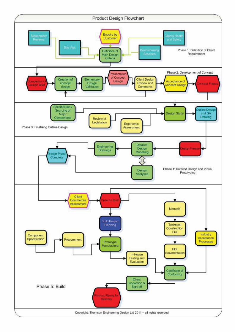
Bespoke Product Design System
Our system for the design and development of new products - like the Troughing Cable Installer - is approved by TUV to ISO 9001:2008 and is encapsulated in the fl ow chart opposite.
Th e key to any product development is the development of a realistic design brief which captures all the necessary and all the desirable features of the proposed product. Changes to the design brief during development are costly and time consuming so it is vital that the specifi cation is carefully though out.
To do this we usually start with a kick-off meeting with all the stakeholders - not just the client’s engineers, managers and purchasing authority but the personnel who will end up using the product daily.
Nothing gets people talking and thinking like a picture so we spend a lot of time in the early stages developing photo-realistic concept images of new products to ensure that everybody is in agreement about the key features of the proposed design.
Many products which we have designed are manufactured by our clients and to ensure that this is achieved with the minimum of diffi culty all engineering drawings and technical documentation is produced by a qualifi ed and experienced engineer.
In this way we have successfully brought more than sixty products successfully into the workplace in the last eight years.
Th omson Engineering Design LtdValley RoadCinderfordGloucestershireGL14 2NZTel: 01594 82 66 11Fax: 01594 82 55 60Email: [email protected]

Th omson Engineering Design Ltd. Valley Road, Cinderford, Gloucestershire. GL14 2NZTel: +44 (0) 1594 82 66 11 Fax: +44 (0) 1594 82 55 60 Email: [email protected]