c-lube linear way ml linear way l - ikont.co.jp · Ⅱ̶3 Ⅱ̶4 c-lube linear way ml linear way l...
TRANSCRIPT

Ⅱ̶3 Ⅱ̶4
C-Lube Linear Way MLLinear Way L
英_Ⅱ_003-022特長L.indd 3-4 11.6.2 10:22:29 AM

LWLLinear Way L
ML Aquamarine endplate for identification of C-Lube Linear Way
C-Lube maintenance free series
C-Lube Linear Way ML
Slide unit
Casing
C-Lube
Steel balls
Endplate
End seal
Ball retaining band
Oil hole
Track rail
Ⅱ̶6
S
1N=0.102kgf=0.2248lbs.1mm=0.03937inchⅡ̶5
Identifi cation number and specifi cation The specifications of ML(F) series and LWL(F) series are indicated by the identifi cation number, consisting of a model code, a size, a part code, a preload symbol, a classifi cation symbol and any supplemental codes.
Interchangeable pecifi cation 1 2 4 5 6 3 7 8 9 10 11Slide unit only ML C 12 C1 T1 P S1 /U
Track rail only(1) LWL 12 R200 B P S1
Assembled set ML C 12 C1 R200 T1 P S1 /U
Non interchangeable specifi cation
Assembled set ML C 12 C1 R200 B T1 P /U
Series1Length of slide unit2
Model
codeOn page Ⅱ̶7
Ball Retaining3
Size4Size On page Ⅱ̶7
Number of slide units5Part
codeOn page Ⅱ̶7
Length of track rail6
Material7Material
symbolOn page Ⅱ̶7
Preload amount8Preload
symbolOn page Ⅱ̶13
Accuracy class9Classifi cation
symbolOn page Ⅱ̶14
Interchangeable10Interchangeable
codeOn page Ⅱ̶15
Special specifi cation11Supplemental
codeOn page Ⅱ̶15
Note(1): For the model code of track rail of interchangeable specifi cation, indicate “LWL…B” or “LWLF…B” regardless of the slide unit type to
be combined.
Features
Simple structure of smallest size
A micro miniature linear motion rolling guide is produced by the simple structure of two-row and four-point contact and original small sizing technology. The smallest size, LWL1 is truck rail width of only 1mm.
Wide variation corresponding to needs
Two shapes of track rail, standard type and wide type are lined up with four variations in length of slide unit. Wide type track rail is suitable for use of mono rail. Moreover, tapped type track rail, which has machined female threads, are available for optimal products to fi t for requirement of machine and equipment.
Stainless Steel
The metal components are manufactured from corrosion resistant stainless steel. So this series is most suitable for use in clean rooms and also for applications where the use of lubricants and rust preventive oil should be avoided or kept to a minimum.
Ball retained type
The slide unit incorporates ball retaining bands, which prevent steel balls from dropping when the slide unit is separated from the track rail. So handling is easy.
Variety specifi cation for special environment
Special Environment C-Lube Linear Way ML is serialized. High speed and low noise specification with silicon nitrified ceramic ball.
英_Ⅱ_003-022特長L.indd 5-6 11.6.2 10:22:30 AM

Ⅱ̶7
S
Ⅱ̶8
S
1N=0.102kgf=0.2248lbs.1mm=0.03937inch
-Number of slide unit・Length of track rail・Material-Identifi cation number and specifi cation -Series・Length of slide unit・Ball Retaining・Size-
C-Lube Linear Way L(ML(F) Series)
Standard typeWide type
:ML:MLF
Linear Way L(1)(LWL(F) Series)
Standard typeWide type
:LWL:LWLF
Applicable size and shape of slide unit are shown in Table 2.1 and 2.2.The specifi cation of C-Lube Linear Way ML is indicated by the identifi cation number, consist-ing of a model code, a size, a part code, a preload symbol, a classifi cation symbol and any supplemental codes. For details of each specifi cation, see page 78.
Note(1): For the model code of a single track rail of interchangeable specifi cation, indicate “LWL…B” or “LWLF…B” regardless of the slide unit type to be combined.
ShortStandardHigh rigidity longExtra high rigidity long
:C:No symbol:G: L
Applicable size and shape of slide unit are shown in Table 2.1 and 2.2.
Applicable size and shape of slide unit are shown in Table 2.1 and 2.2.
Standard type 1, 2, 3, 5, 7, 9, 12, 15, 20, 25
Wide type 4, 6, 10, 14, 18, 24, 30, 42
Applicable size and shape of slide unit are shown in Table 2.1 and 2.2.
:C○ For an assembled set, indicate the number of slide units assembled on one track rail. For a slide unit, only “C1” can be indicated.
:R○ Indicate the length of track rail in mm. For standard and maximum lengths, see “Track rail length” in Table 3.1, Table 3.2 and Table 3.3.
Stainless steelHigh carbon steel
:No symbol:CS
Applicable size and shape of slide unit are shown in Table 2.1 and 2.2.
Series1
Length of slide unit2
Ball Retaining3 Table 1.1 Structure of ML and LWL
Series Shape and size of track rail Ball Retaining
ML Standard track rail Ball retained type: No symbol
LWL
Standard track rail Ball retained type: B
Tapped track railMounting from bottom
Size 2, 3 Ball non-retained type: No symbolSize 5, 7, 9 Ball retained type: N
Mounting from lateral Size 1 Ball non-retained type: YNon-mounting hole type track rail Size 1 Ball non-retained type: No symbol
Table 1.1 Structure of MLF and LWLF
Series Shape of track rail Ball Retaining
MLF Standard track rail Ball retained type: No symbol
LWLFStandard track rail
Size 4, 6 Ball non-retained type: No symbolSize 10 to 42 Ball retained type: B
Tapped track railSize 6 Ball non-retained type
: NSize 10 to 18 Ball retained type
Size4
Number of slide unit5
Length of track rail6
Material7
Table 2.1 Models and sizes of ML(F) and LWL(F) series
Shape of track rail Material Length of slide unit Ball Retaining SeriesSize
1 2 3 5 7 9 12 15 20 25
Sta
inle
ss s
teel
mad
e
Ball retained type
MLC - - - ○ ○ ○ ○ ○ ○ ○
LWLC…B - - - ○ ○ ○ ○ ○ ○ ○
ML - - - ○ ○ ○ ○ ○ ○ ○
LWL…B - - - ○ ○ ○ ○ ○ ○ ○
MLG - - - - ○ ○ ○ ○ ○ ○
LWLG…B - - - - ○ ○ ○ ○ ○ ○
High
car
bon
stee
l mad
e
MLL - - - - - ○ ○ ○ - -
LWL…BCS - - - - - ○ ○ ○ ○ -
Sta
inle
ss s
teel
mad
e
Ball non-retained type
LWLC - - ○ - - - - - - -
Ball retained type
LWLC…N - - - ○ ○ ○ - - - -
Ball non-retained type
LWL - ○ ○ - - - - - - -
Ball retained type
LWL…N - - - ○ ○ ○ - - - -
Ball retained type
LWLG…N - - - - ○ ○ - - - -
Ball non-retained type
LWL…Y ○ - - - - - - - - -
Ball non-retained type
LWL ○ - - - - - - - - -
Remark : The mark indicates that interchangeable specifi cation is available.
Standard track rail
Short
Standard
High rigidity long
Extra high rigidity long
Standard
Tapped track rail
Short
Standard
High rigidity long
Tapped track rail(Lateral)
Standard
Non-mounting holetype track rail
Standard
英_Ⅱ_003-022特長L.indd 7-8 11.6.2 10:22:50 AM
Ⅱ̶9
S
Ⅱ̶10
S
1N=0.102kgf=0.2248lbs.1mm=0.03937inch
-Series・Length of slide unit・Ball Retaining・Size ・Material- -Track rail length-
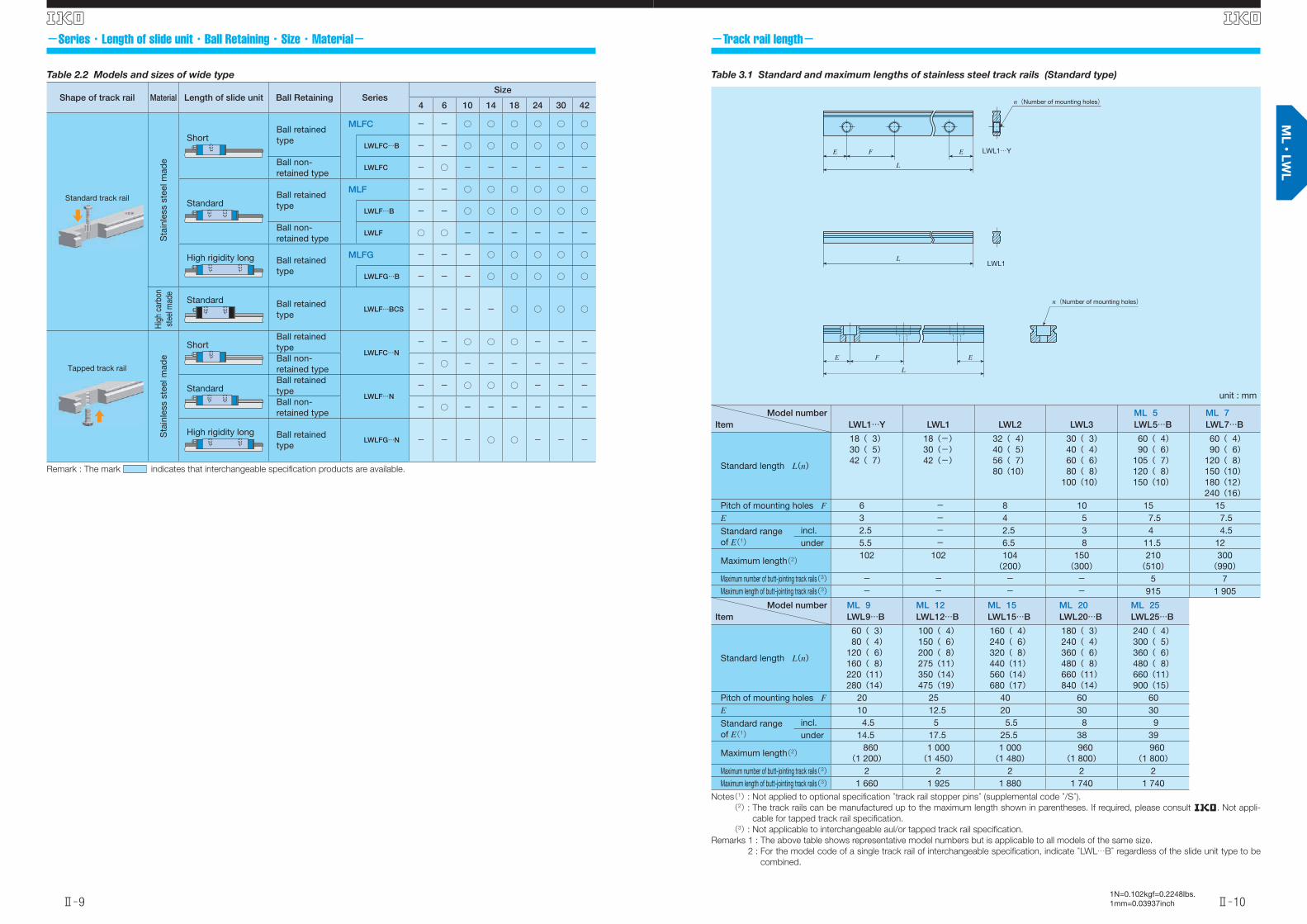
Table 3.1 Standard and maximum lengths of stainless steel track rails (Standard type)
unit : mm
Model numberItem LWL1…Y LWL1 LWL2 LWL3
ML 5LWL 5…B
ML 7LWL 7…B
Standard length L(n)
18( 3)30( 5)42( 7)
18(-)30(-)42(-)
32( 4)40( 5)56( 7)80(10)
30( 3)40( 4)60( 6)80( 8)
100(10)
60( 4)90( 6)
105( 7)120( 8)150(10)
60( 4)90( 6)
120( 8)150(10)180(12)240(16)
Pitch of mounting holes F 6 - 8 10 15 15E 3 - 4 5 7.5 7.5
Standard rangeof E(1)
incl. 2.5 - 2.5 3 4 4.5under 5.5 - 6.5 8 11.5 12
Maximum length(2) 102 102 104(200)
150(300)
210(510)
300(990)
Maximum number of butt-jointing track rails(3) - - - - 5 7Maximum length of butt-jointing track rails(3) - - - - 915 1 905
Model numberItem
ML 9LWL 9…B
ML 12LWL 12…B
ML 15LWL 15…B
ML 20LWL 20…B
ML 25LWL 25…B
Standard length L(n)
60( 3)80( 4)
120( 6)160( 8)220(11)280(14)
100( 4)150( 6)200( 8)275(11)350(14)475(19)
160( 4)240( 6)320( 8)440(11)560(14)680(17)
180( 3)240( 4)360( 6)480( 8)660(11)840(14)
240( 4)300( 5)360( 6)480( 8)660(11)900(15)
Pitch of mounting holes F 20 25 40 60 60E 10 12.5 20 30 30
Standard rangeof E(1)
incl. 4.5 5 5.5 8 9under 14.5 17.5 25.5 38 39
Maximum length(2) 860(1 200)
1 000(1 450)
1 000(1 480)
960(1 800)
960(1 800)
Maximum number of butt-jointing track rails(3) 2 2 2 2 2Maximum length of butt-jointing track rails(3) 1 660 1 925 1 880 1 740 1 740
Notes(1) : Not applied to optional specifi cation “track rail stopper pins” (supplemental code “/S”).(2) : The track rails can be manufactured up to the maximum length shown in parentheses. If required, please consult R. Not appli-
cable for tapped track rail specifi cation.
(3) : Not applicable to interchangeable aul/or tapped track rail specifi cation.
Remarks 1 : The above table shows representative model numbers but is applicable to all models of the same size.
2 : For the model code of a single track rail of interchangeable specifi cation, indicate “LWL…B” regardless of the slide unit type to be
combined.
L
E EF
LWL1…Y
LWL1
n(Number of mounting holes)
n(Number of mounting holes)
E F
L
E
L
Table 2.2 Models and sizes of wide type
Shape of track rail Material Length of slide unit Ball Retaining SeriesSize
4 6 10 14 18 24 30 42
Sta
inle
ss s
teel
mad
e
Ball retained type
MLFC - - ○ ○ ○ ○ ○ ○
LWLFC…B - - ○ ○ ○ ○ ○ ○
Ball non-retained type
LWLFC - ○ - - - - - -
Ball retained type
MLF - - ○ ○ ○ ○ ○ ○
LWLF…B - - ○ ○ ○ ○ ○ ○
Ball non-retained type
LWLF ○ ○ - - - - - -
Ball retained type
MLFG - - - ○ ○ ○ ○ ○
LWLFG…B - - - ○ ○ ○ ○ ○
High
car
bon
stee
l mad
e
Ball retained type
LWLF…BCS - - - - ○ ○ ○ ○
Sta
inle
ss s
teel
mad
e
Ball retained type
LWLFC…N- - ○ ○ ○ - - -
Ball non-retained type
- ○ - - - - - -
Ball retained type
LWLF…N- - ○ ○ ○ - - -
Ball non-retained type
- ○ - - - - - -
Ball retained type
LWLFG…N - - - ○ ○ - - -
Remark : The mark indicates that interchangeable specifi cation products are available.
Standard track rail
Short
Standard
High rigidity long
Standard
Tapped track rail
Short
Standard
High rigidity long
英_Ⅱ_003-022特長L.indd 9-10 11.6.2 10:22:53 AM

Ⅱ̶11
S
Ⅱ̶12
S
1N=0.102kgf=0.2248lbs.1mm=0.03937inch
-Track rail length--Track rail length-
Table 3.3 Standard and maximum lengths of high carbon steel track rails (Standard type, Wide rail type)
unit : mm
Model numberItem
LWL 9…BCS LWL12…BCS LWL15…BCS LWL20…BCS
Standard length L(n)
80( 4)160( 8)220(11)280(14)380(19)500(25)600(30)
100( 4)200( 8)275(11)350(14)475(19)600(24)700(28)
160( 4)320( 8)440(11)560(14)680(17)800(20)920(23)
180( 3)240( 4)360( 6)480( 8)660(11)900(15)
1 020(17)Pitch of mounting holes F 20 25 40 60E 10 12.5 20 30
Standard rangeof E(1)
incl. 4.5 5 5.5 8under 14.5 17.5 25.5 38
Maximum length 1 000 1 500 1 520 1 560
Model numberItem
LWLF18…BCS LWLF24…BCS LWLF30…BCS LWLF42…BCS
Standard length L(n)
90( 3)180( 6)240( 8)300(10)420(14)510(17)600(20)
120( 3)240( 6)320( 8)400(10)600(15)720(18)800(20)
160( 4)320( 8)440(11)560(14)680(17)800(20)920(23)
160( 4)320( 8)440(11)560(14)680(17)800(20)920(23)
Pitch of mounting holes F 30 40 40 40E 15 20 20 20
Standard rangeof E(1)
incl. 5.5 6.5 6.5 6.5under 20.5 26.5 26.5 26.5
Maximum length 1 500 1 520 1 600 1 600
Note(1) : Not applied to optional specifi cation “track rail stopper pins” (supplemental code “/S”).Remark : The above table shows representative model numbers but is applicable to all models of the same size.
n(Number of mounting holes)
L
E EF
LWLF 42…BCSLWLF…BCSLWL…BCS
n(Number of mounting holes)
2×n(Number of mounting holes)
Table 3.2 Standard and maximum lengths of stainless steel track rails (Wide rail type)
unit : mm
Model numberItem LWLF4 LWLF6
MLF 10LWLF 10…B
MLF 14LWLF 14…B
Standard length L(n)
40( 4)60( 6)70( 7)80( 8)
100(10)
60( 4)90( 6)
105( 7)120( 8)150(10)
60( 3)80( 4)
120( 6)160( 8)220(11)280(14)
90( 3)120( 4)150( 5)180( 6)240( 8)300(10)
Pitch of mounting holes F 10 15 20 30E 5 7.5 10 15
Standard rangeof E(1)
incl. 3.5 4.5 4.5 5.5under 8.5 12 14.5 20.5
Maximum length(2) 180(300)
240(300)
300(500)
300(990)
Maximum number of butt-jointing track rails(3) - - 7 8Maximum length of butt-jointing track rails(3) - - 1 840 1 950
Model numberItem
MLF 18LWLF 18…B
MLF 24LWLF 24…B
MLF 30LWLF 30…B
MLF 42LWLF 42…B
Standard length L(n)
90( 3)120( 4)150( 5)180( 6)240( 8)300(10)
120( 3)160( 4)240( 6)320( 8)400(10)480(12)
160( 4)240( 6)320( 8)440(11)560(14)680(17)
160( 4)240( 6)320( 8)440(11)560(14)680(17)
Pitch of mounting holes F 30 40 40 40E 15 20 20 20
Standard rangeof E(1)
incl. 5.5 6.5 6.5 6.5under 20.5 26.5 26.5 26.5
Maximum length(2) 690(1 860)
680(1 960)
680(2 000)
680(2 000)
Maximum number of butt-jointing track rails(3) 3 3 3 3Maximum length of butt-jointing track rails(3) 1 920 1 840 1 840 1 840
Notes(1) : Not applied to optional specifi cation “track rail stopper pins” (supplemental code “/S”).(2) : The track rails can be manufactured up to the maximum length shown in parentheses. If required, please consult R. Not appli-
cable for tapped track rail specifi cation.
(3) : Not applicable to interchangeable aul/or tapped track rail specifi cation.
Remarks 1 : The above table shows representative model numbers but is applicable to all models of the same size.
2 : For the model code of track rail of interchangeable specifi cation, indicate “LWL…B” regardless of the slide unit type to be com-
bined.
LWLF 42…B
n(Number of mounting holes)
2×n(Number of mounting holes)
L
E EF
英_Ⅱ_003-022特長L.indd 11-12 11.6.2 10:22:56 AM

Ⅱ̶13
S
Ⅱ̶14
S
1N=0.102kgf=0.2248lbs.1mm=0.03937inch
-Accuracy--Preload amount-
High classPrecision class
:H:P
In interchangeable specifi cation, please combine same accuracy codes on both slide unit and track rail. For detail of accuracy, see Table 6.1 and 6.2.Accuracy class is not applicable to size 1.
Accuracy class9ClearanceStandardLight preload
:T0
:No symbol:T1
Specify this items for an assembled set or an inter-changeable single slide unit. Applicable preload and size are shown in Table 4. For detail of preload amount, see Table 5.1 and 5.2.
Preload amount8
Table 4 Preload amount
Item
Preload typeSymbol
Preload amount
NApplication
Clearance T0 0(1) ・ Very smooth motionStandard (No symbol) 0(2) ・ Smooth and precise motion
Light preload T1 0.02 C0
・Minimum vibration・ Load is evenly balanced・ Smooth and precise motion
Notes(1) : Zero or minimal amount of clearance.
(2) : Zero or minimal amount of preload.
Remark : C0 means the basic static load rating.
Table 5.1 Applicable preload (standard type)
Size
Preload and symbol
Clearance Standard Light preload(T0) (No symbol) (T1)
1 ○ - -2 ○ - -3 ○ - -5 ○ ○ -7 ○(1) ○ ○(1)9 ○(1) ○ ○(1)
12 ○(1) ○ ○(1)15 ○(1) ○ ○(1)20 ○ ○ ○25 ○ ○ ○
Note(1) : Not applicable to /HB (ceramic ball) specifi cation.
Remark : The mark indicates that interchangeable specifi ca-
tion products are available.
Table 5.2 Applicable preload (Wide type)
Size
Preload and symbol
Clearance Standard Light preload(T0) (No symbol) (T1)
4 ○ - -6 ○ - -
10 ○ ○ -14 ○ ○ ○18 ○ ○ ○24 ○ ○ ○30 ○ ○ ○42 ○ ○ ○
Remark : The mark indicates that interchangeable specifi ca-
tion products are available.
Table 6.1 Accuracy for LWL 1
unit : mm
Item Tolerance
Dim. H tolerance ±0.020
Dim. N1 and N2 tolerance ±0.025
H
N1 N2
C
A
BD1 D2
Fig. 1 Parallelism in operation for Size 2 or larger
Length of track rail L mm
Par
alle
lism μ
m
0
10
20
30
0 500 15001000 2000
Precision(P)
High(H)
Table 6.2 Accuracy for size 2 or larger
unit : mm
Classifi cation(Symbol)
Item
High Precision
(H) (P)
Dim. H tolerance ±0.020 ±0.010Dim. N tolerance ±0.025 ±0.015Dim. variation of H(1) 0.015 0.007Dim. variation of N(1) 0.020 0.010Dim. variation of H for multiple assembled sets(2) 0.030 0.020Parallelism in operationof C to A
See Fig. 1
Parallelism in operationof D to B
See Fig. 1
Notes(1) : It means the size variation between slide units mounted on
the same track rail.
(2) : It applies to the interchangeable specifi cation.
N
C
D B
H
A
英_Ⅱ_003-022特長L.indd 13-14 11.6.2 10:22:57 AM

Ⅱ̶15
S
Ⅱ̶16
S
1N=0.102kgf=0.2248lbs.1mm=0.03937inch
-Special specifi cations--Interchangeable・Special specifi cations-
Interchangeable
Non-interchangeable
:S1:S2:No symbol
Specity this code for the interchangeable specifi cation products. Assemble track rails and slide units with the same interchangeable code.For applicalble models and sizes, see Table 2.1 and 2.2.
For applicable special specifications, see Table 7.1, 7.2, 7.3 and 7.4. When several special speci-fi cations are required, see Table 8. Special specifi -cations are not applicable to size 1.For details of special specifi cations, see page Ⅲ̶28.
Interchangeable10
Special specifi cations11
Table 7.1 Applicable specifi cations(Interchangeable specifi cation, single slide unit)
Specifi cationsSupplemental
code
Size
1 2 3 5 7 9 12 15 20 25
- 4 6 10 14 18 24 30 42 -
No rubber end seals /N - - - ○ ○ ○ ○ ○ ○ ○C-Lube plates(1) /Q - - - ○ ○ ○ ○ ○ ○ ○Under seals /U - - - × × ○ ○ ○ ○ ○
Note(1) : Applicable to LWL(F) series.
Table 7.2 Applicable specifi cations(Interchangeable specifi cation, track rail)
Specifi cationsSupplemental
code
Size
1 2 3 5 7 9 12 15 20 25
- 4 6 10 14 18 24 30 42 -
Specifi ed rail mounting hole positions /E - - - ○ ○ ○ ○ ○ ○ ○Without track rail mounting bolts /MN - - - ○ ○ ○ ○ ○ ○ ○
Table 7.3 Applicable specifi cations(Interchangeable specifi cation, assembled set)
Specifi cationsSupplemental
code
Size
1 2 3 5 7 9 12 15 20 25
- 4 6 10 14 18 24 30 42 -
Opposite reference surfaces arrangement /D - - - ○ ○ ○ ○ ○ ○ ○Specifi ed rail mounting hole positions /E - - - ○ ○ ○ ○ ○ ○ ○Without track rail mounting bolts(1) /MN - - - ○ ○ ○ ○ ○ ○ ○No rubber end seals /N - - - ○ ○ ○ ○ ○ ○ ○C-Lube plates(2) /Q - - - ○ ○ ○ ○ ○ ○ ○Under seals /U - - - × × ○ ○ ○ ○ ○
Notes(1) : Not applicable to tapped track rail specifi cation.
(2) : Applicable to LWL(F) series.
Table 7.4 Applicable specifi cations(Non-interchangeable specifi cation)
Specifi cationsSupplemental
code
Size
1 2 3 5 7 9 12 15 20 25
- 4 6 10 14 18 24 30 42 -
Butt jointing track rail(1)(2) /A × × × ○ ○ ○ ○ ○ ○ ○Stainless steel end plates(3) /BS × ○(4) ○(4) ○ ○ ○ ○ ○ ○ ×Opposite reference surfaces arrangement /D × ○ ○ ○ ○ ○ ○ ○ ○ ○Specifi ed rail mounting hole positions /E × ○ ○ ○ ○ ○ ○ ○ ○ ○Ceramic ball specifi cation(5) /HB × × × × ○(5) ○(5) ○(5) ○(5) × ×Appending inspection sheet /11 × ○ ○ ○ ○ ○ ○ ○ ○ ○Black chrome surface treatment(track rail) /LR × × × × ○ ○ ○ ○ ○ ○Without track rail mounting bolts(2) /MN × ○(6) ○(6) ○ ○ ○ ○ ○ ○ ○No rubber end seals /N × × × ○ ○ ○ ○ ○ ○ ○C-Lube plates(3) /Q × × × ○ ○ ○ ○ ○ ○ ○Seals for special environment(3) /RE × × × ○ ○ ○ ○ ○ ○ ×Track rail with stopper pins /S × × × ○ ○ ○ ○ ○ ○ ○Under seals /U × × × × × ○ ○ ○ ○ ○Matched sets to be used as an assembled group /W○ × ○ ○ ○ ○ ○ ○ ○ ○ ○Specifi ed grease(3) /Y○ × ○(7) ○ ○ ○ ○ ○ ○ ○ ○
Notes(1) : Not applicable to high carbon steel type.
(2) : Not applicable to tapped rail specifi cation products.
(3) : Applicable to LWL(F) series.
(4) : Not applicable to size 4 and 6 models.
(5) : Applicable to size 7, 9, 12 and 15 of ML series.
(6) : Not applicable to size 2 and 3 models.
(7) : Only applicable to / YNG.
Table 8 Combination of special specifi cations
BS ○D ○ ○E - ○ -
HB ○ - ○ ○11 ○ ○ ○ ○ ○LR - ○ ○ ○ ○ ○MN ○ ○ ○ ○ ○ ○ ○N ○ ○ ○ ○ ○ ○ ○ ○Q ○ ○ ○ ○ - ○ ○ ○ ○
RE ○ ○ ○ ○ - ○ ○ ○ - ○S ○ ○ ○ ○ ○ ○ ○ ○ ○ ○ ○U ○ ○ ○ ○ ○ ○ ○ ○ - ○ - ○W ○ ○ ○ - ○ ○ ○ ○ ○ ○ ○ ○ ○Y ○ ○ ○ ○ - ○ ○ ○ ○ - ○ ○ ○ ○
A BS D E HB 1 LR MN N Q RE S U W
Remarks 1 : In the table, the mark ○ indicates that this combina-
tion can be made.
2 : When a combination of several special specifi cations
is required, arrange their supplemental codes in al-
phabetical order.
英_Ⅱ_003-022特長L.indd 15-16 11.6.2 10:22:58 AM

Ⅱ̶17
S
Ⅱ̶18
S
1N=0.102kgf=0.2248lbs.1mm=0.03937inch
Lubrication -Special specifi cations- Dust protection In ML(F) and LWL(F) series, lithium soap base grease (MULTEMP PS No.2, KYODO YUSHI) is pre-packed. Addi-tion to ML(F) series, self lubrication system C-Lube is as-sembled and it extends to re-lubrication interval longer.In ML(F) and LWL(F) series, grease nipple and oil holes are prepared as shown in Table 13 and Table 14. Supply nozzles fi t to each shapes of grease nipple and miniature greasers fi t to oil holes are also available. For these parts for lubrication, refer to Table 14 and Table 15.1 on page Ⅲ̶22, and Table 16 on page 23 if required. In models of size 1 to 6, put grease directly to their raceway of track rail because oil hole is not prepared.
The slide units of ML(F) and LWL(F) series are provided with special rubber seals for dust protection. However, if a large amount of file contaminants are present, or if large particles of foreign matter may fall on the track rail, it is rec-ommended to provide bellows and other protective covers by customer. Especially in models of size 1 to 6, end seals are not prepared.
Table 9 Slide unit with C-Lube plates (Supplemental code /Q)
unit : mm
Model number L1 L4 Model number L1 L4
LWLC 5…B 22 - LWLFC 10…B 26.5 -LWL 5…B 25 - LWLF 10…B 30.5 -LWLC 7…B 27 - LWLFC 14…B 30.5 -LWL 7…B 31.5 - LWLF 14…B 39.5 -LWLG 7…B 39 - LWLFG 14…B 50 -LWLC 9…B 30 - LWLFC 18…B 34.5 -LWL 9…B 39 - LWLF 18…B 46.5 -LWLG 9…B 49 - LWLFG 18…B 58.5 -LWLC 12…B 33 - LWLFC 24…B 38.5 -LWL 12…B 42 - LWLF 24…B 52 -LWLG 12…B 52 - LWLFG 24…B 67 -LWLC 15…B 42 47 LWLFC 30…B 45.5 50LWL 15…B 52 57 LWLF 30…B 59.5 64LWLG 15…B 67 72 LWLFG 30…B 78.5 83LWLC 20…B 48 53 LWLFC 42…B 51.5 56LWL 20…B 60 65 LWLF 42…B 65 70LWLG 20…B 78 83 LWLFG 42…B 84.5 89LWLC 25…B 63.5 74LWL 25…B 87.5 98LWLG 25…B 107.5 117
Remarks 1 : The values are the slide unit lengths with C-Lube plates
at both ends.
2 : The above table shows representative model numbers
but is applicable to all models.
C-Lube plate C-Lube plate(L1)
(L4)
Table 11 Track rail with stopper pins (Supplemental code /S)
unit : mm
Size a b c
5 - 2 2 1.67 -
2.5
2.52
9 - 3- 10 2 1.612 -
3
2
- 1415 - 4- 18 320 - 5- 24 325 - 3.5 5- 30
2.54
- 42 5
a
c
b
Table 10 Rated load and moment for C-Lube Linear Way Ceramic Ball Specifi cation(Supplemental code /HB)
Model numberC C0 T0 TX(1) TY(1)N N N・m N・m N・m
MLC 7…/HB 937 965 3.5 1.612.6
1.310.6
ML 7…/HB 1 330 1 610 5.9 4.023.9
3.320.1
MLG 7…/HB 1 690 2 250 8.2 7.543.1
6.336.2
MLC 9…/HB 1 180 1 260 5.9 2.418.2
2.115.3
ML 9…/HB 1 810 2 340 10.9 7.743.4
6.536.4
MLG 9…/HB 2 370 3 420 15.9 15.983.6
13.470.1
MLL 9…/HB 2 870 4 500 20.9 27.1134
22.7112
MLC 12…/HB 2 210 2 030 12.6 4.535.5
3.829.8
ML 12…/HB 3 330 3 650 22.6 13.179.2
11.066.4
MLG 12…/HB 4 310 5 270 32.7 26.0143
21.9120
MLL 12…/HB 5 820 8 110 50.3 59.3288
49.8242
MLC 15…/HB 3 490 3 310 25.5 9.971.8
8.360.3
ML 15…/HB 4 980 5 520 42.5 25.3146
21.2122
MLG 15…/HB 6 620 8 280 63.7 54.3288
45.5241
MLL 15…/HB 8 370 11 600 89.2 104497
86.9417
Note(1) : The upper values in the TX and TY columns apply to one
slide unit, and the lower values apply to two slide units in
close contact.
Table 12 H1 dimension of slide unit with under seals (Supplemental code /U)
unit : mm
Size H1
9 - 112 - 215 - 3- 18 220 - 4- 24 225 - 5(1)- 30 2- 42 3
Note(1) : This dimension is the same as that without under seals.
H1
Table 13 Oil hole
unit : mm
Size d1 d2
5 10
0.5
1.17 14 1.29 18 1.5
12 24 2
d 1
d 2
End seal
Rubber part of end seal End plate
Casing
Table 14 Parts for lubrication
Size Grease nipple(1) Applicable supply nozzle type Nominal size of female threals for piping
5, 7, 9, 12 10, 14, 18, 24 Oil hole Miniature greaser-
15, 20 30, 42 A-M3A-5120V A-5240VB-5120V B-5240V
25 - B-M4A-8120VB-8120V
M4
Note(1) : In grease nipple specifi cation please see Table 15.1 on page Ⅲ̶22.
英_Ⅱ_003-022特長L.indd 17-18 11.6.2 10:23:00 AM

Ⅱ̶19
S
Ⅱ̶20
S
1N=0.102kgf=0.2248lbs.1mm=0.03937inch
Precautions for Use ❶ Mounting surface, reference mounting surface, and gen-
eral mounting structureTo mount ML(F) and LWL(F) series, correctly fi t the refer-ence mounting surfaces B and D (D1 or D2) of the slide unit and track rail to the reference mounting surfaces of the table and the bed, and then fi x them tightly. (See Fig.2) In size 1, reference surfaces are available to both side of slide unit. (D1 and D2)Track rail of LWL1…Y can be mounted in lateral direction.Two kinds of mounting methods can be chosen. (See Fig.3.1 and 3.2)The reference mounting surfaces B and D (D1 and D2) and the mounting surfaces A and C of ML(F) and LWL(F) series are accurately fi nished by grinding. Stable and high accura-cy liner motion can be obtained by finishing the mating mounting surfaces of machines or equipment with high ac-curacy and correctly mounting the guide on these surfaces.Reference mounting surfaces of slide unit and track rail are shown in Fig. 5.2.
Fig. 2 Reference mounting surface and generalmounting structure
C
D2
B
A
Fig. 3.1 Reference mounting surface and generalmounting structure ① of LWL1… Y
D
C
A
B
Fig. 3.2 Reference mounting surface and generalmounting structure ② of LWL1… Y
D
C
A
B
Fig. 4 Reference mounting surface and general mounting structure of LWL 2, 3, 4 and 6.
Track rail Slide unitReference mounting
surface
mark
BD1
D2
Fig. 5.1 Reference mounting surface of LWL1
Fig. 5.2 Reference mounting surface and generalmounting structure of LWL2 or larger
D1
C
A
B
Track rail Slide unit
mark mark
Reference mounting surface
BD
❷ Female threads for mounting the slide unit and track rail are through holes
In the slide unit, mounting holes are through the slide unit. For mounting slide unit, insertion depth shown in dimension table must be kept. Too deep insertion depth causes inter-ference to the track rail and it leads trouble for running ac-curacy, frictional resistance and lifetime.In the size of 1, crossed recessed head screw for precision equipment (head diameter 1.8mm or smaller) is recom-mended.
❸The mounting bolts for track rail are not appendedIn the size of 2 and 3 of lateral mounting type, track rail mounting bolts are not appended. Prepare mounting bolts which insertion depth must be less than H4 in dimension when mounting.
❹ Corner radius and shoulder height of reference mount-ing surfaces
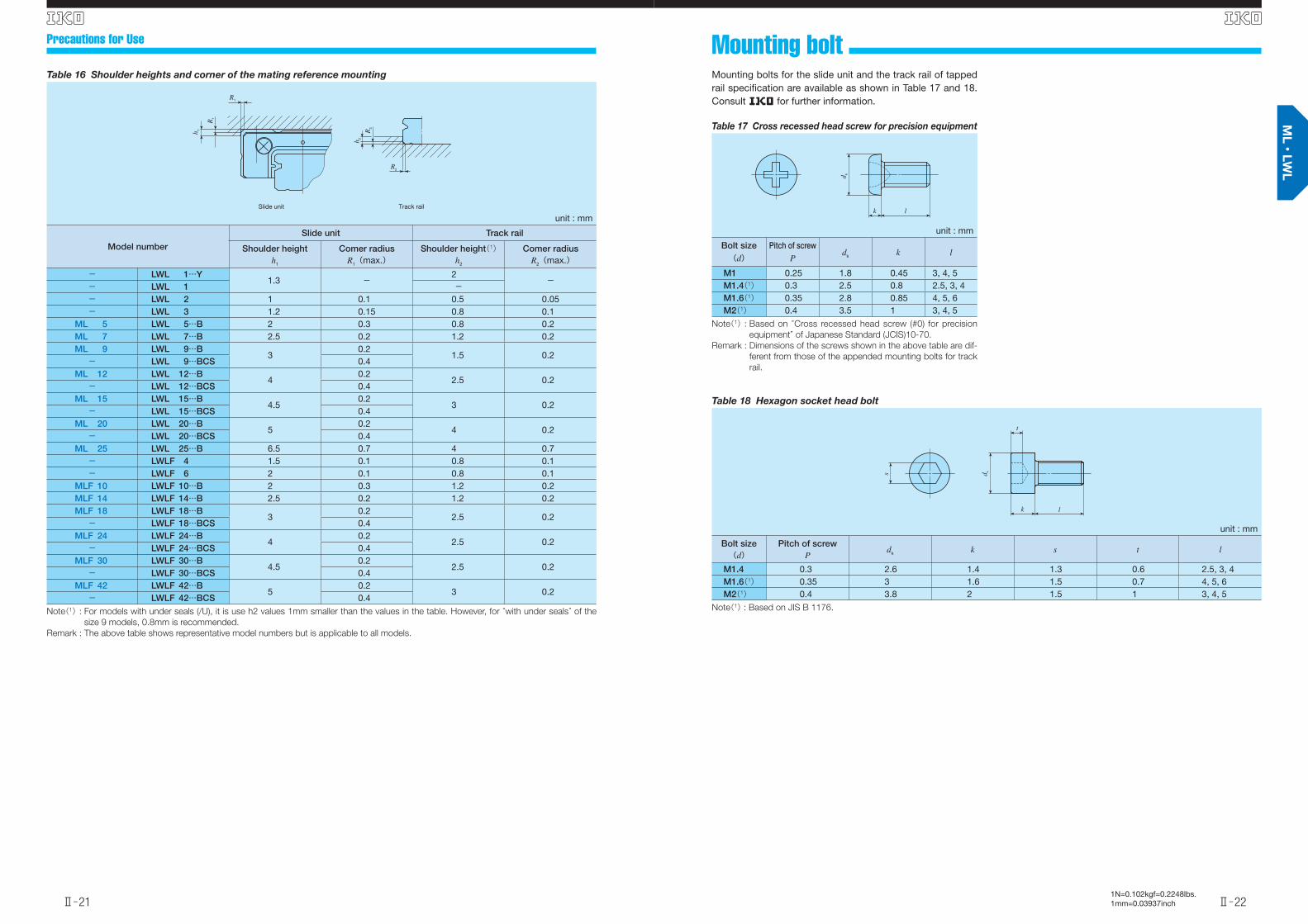
It is recommended to make relieved fillet at the corner of mating reference mounting surfaces as shown in Fig.6. Ta-ble 16 shows recommended shoulder heights corner radii of the mating surfaces.
Fig. 6 Relieved fi llet at the corner of the mating reference mounting surfaces
❺Tightening torque of mounting boltsThe standard torque values for ML(F) and LWL(F) series mounting bolts are shown in Table 15. When machines or equipment are subjected to serve vibration, shock, large fl uctuating load, or moment load, the bolts should be tight-ened with a torque 1.2 to 1.5 times higher than the standard torque values shown. When the mating member material is cast iron or aluminum, tightening torque should be lowered in accordance with strength characteristics of the material.
Table 15 Tightening torque of mounting bolts
Bolt sizeTightening torque N・m
Stainless steel bolt Carbon steel bolt
M1 ×0.25 0.04 -M1.4×0.3 0.10 -M1.6×0.35 0.15 -M2 ×0.4 0.31 -M2.5×0.45 0.62 -M3 ×0.5 1.1 1.2M4 ×0.7 2.5 2.8M5 ×0.8 5.0 5.6M6 ×1 8.5 -
Remarks 1 : The values are calculated by bolt strength division 8.8.
as a basis.
2 : In the size of 1, it is recommended to be 70 to 80% of
the values in the table.
英_Ⅱ_003-022特長L.indd 19-20 11.6.2 10:23:01 AM
Ⅱ̶21
S
Ⅱ̶22
S
1N=0.102kgf=0.2248lbs.1mm=0.03937inch
Mounting bolt Precautions for Use
Mounting bolts for the slide unit and the track rail of tapped rail specifi cation are available as shown in Table 17 and 18. Consult R for further information.
Table 17 Cross recessed head screw for precision equipment
unit : mm
Bolt size Pitch of screwdk k l(d) P
M1 0.25 1.8 0.45 3, 4, 5M1.4(1) 0.3 2.5 0.8 2.5, 3, 4M1.6(1) 0.35 2.8 0.85 4, 5, 6M2(1) 0.4 3.5 1 3, 4, 5
Note(1) : Based on “Cross recessed head screw (#0) for precision
equipment” of Japanese Standard (JCIS)10-70.
Remark : Dimensions of the screws shown in the above table are dif-
ferent from those of the appended mounting bolts for track
rail.
lk
d k
Table 16 Shoulder heights and corner of the mating reference mounting
unit : mm
Model number
Slide unit Track rail
Shoulder height Comer radius Shoulder height(1) Comer radiush1 R1(max.) h2 R2(max.)
- LWL 1…Y1.3 -
2-
- LWL 1 -- LWL 2 1 0.1 0.5 0.05- LWL 3 1.2 0.15 0.8 0.1
ML 5 LWL 5…B 2 0.3 0.8 0.2ML 7 LWL 7…B 2.5 0.2 1.2 0.2ML 9 LWL 9…B
30.2
1.5 0.2- LWL 9…BCS 0.4
ML 12 LWL 12…B4
0.22.5 0.2
- LWL 12…BCS 0.4ML 15 LWL 15…B
4.50.2
3 0.2- LWL 15…BCS 0.4
ML 20 LWL 20…B5
0.24 0.2
- LWL 20…BCS 0.4ML 25 LWL 25…B 6.5 0.7 4 0.7- LWLF 4 1.5 0.1 0.8 0.1- LWLF 6 2 0.1 0.8 0.1
MLF 10 LWLF 10…B 2 0.3 1.2 0.2MLF 14 LWLF 14…B 2.5 0.2 1.2 0.2MLF 18 LWLF 18…B
30.2
2.5 0.2- LWLF 18…BCS 0.4
MLF 24 LWLF 24…B4
0.22.5 0.2
- LWLF 24…BCS 0.4MLF 30 LWLF 30…B
4.50.2
2.5 0.2- LWLF 30…BCS 0.4
MLF 42 LWLF 42…B5
0.23 0.2
- LWLF 42…BCS 0.4
Note(1) : For models with under seals (/U), it is use h2 values 1mm smaller than the values in the table. However, for “with under seals” of the
size 9 models, 0.8mm is recommended.
Remark : The above table shows representative model numbers but is applicable to all models.
R2
R1
R2
h 2
h 1
R1
Slide unit Track rail
Table 18 Hexagon socket head bolt
unit : mm
Bolt size Pitch of screwdk k s t l(d) P
M1.4 0.3 2.6 1.4 1.3 0.6 2.5, 3, 4M1.6(1) 0.35 3 1.6 1.5 0.7 4, 5, 6M2(1) 0.4 3.8 2 1.5 1 3, 4, 5
Note(1) : Based on JIS B 1176.
lk
d k
t
s
英_Ⅱ_003-022特長L.indd 21-22 11.6.2 10:23:03 AM

C-Lube Linear Way ML
Ⅱ̶24
1N=0.102kgf=0.2248lbs.1mm=0.03937inchⅡ̶23
S S
Model number
Inte
rcha
ngea
ble Mass (Reference)
gDimension of
assemblymm
Dimension of slide unitmm
Dimension of track railmm
Appended mounting bolt for track rail(2)
mm
Basic dynamic load rating(5)
Basic static load rating(5)
Static moment rating(5)
MLLWL
(Non C-Lube)
Slideunit Track rail
(per 100mm) H H1 N W2 L1 L2 L3 M1×depth H2 W H4 H5 M2 d3 E F Bolt size x lengthC
N
C0
N
T0
N・m
TX
N・m
TY
N・m
- LWL 1 …Y -0.16
2.1 4.2 2.21.5 4 6.5 2 3.9 M1 ×0.9 1.2 1
3.1 1.1 M1.4Through 1.1 3 6 M1×Ror M1.4×R(3)
66.8 113 0.06 0.070.47
0.090.56
- LWL 1 - 1.0 2.5 0.5 1.4 - - - - - -
- LWL 2 - 0.9 2.8 3.2 0.7 2 6 12.5 4 8.8 M1.4×1.1 - 2 2 - M1Through - 4 8 M1 ×R(4) 211 381 0.42 0.54
2.90.643.4
- LWLC 3 - 1.05.3 4 1 2.5 8
11.5 3.5 6.7 M1.6×1.3- 3 2.6 - M1.6
Through - 5 10 M1.6×R(4)251 361 0.58 0.39
2.90.473.4
- LWL 3 - 1.6 15.5 5.5 10.7 M2 ×1.3 353 587 0.94 0.985.9
1.27.0
Notes(1) : Track rail lengths are shown in Table 3.1 on page Ⅱ̶10.
(2) : Track rail mounting bolts are not appended.
(3) : Prepare track rail mounting bolts according to mounting structure.
(4) : Fixing thread depth of bolt Rmust be less than H4.
(5) : The direction of basic dynamic load rating(C), basic static load rating(C0)and static moment rating(T0, TX, TY)are shown in the
sketches below. The upper values in the TX and TY columns apply to one slide unit, and the lower values apply to two slide units in
close contact.
Remarks 1 : Metal parts are made of stainless steel.
2 : Do not disassemble a slide unit from the track rail because steel balls are not retained. No end seal is attached.
3 : The specifi cation of small size mounting bolts(M2 and less)are show on page Ⅱ̶22. Consult R if required.
Example of identification number for assembled set
Model code
LWLSize Part code
R80C22
LWL
Series
Standard typeLWL…Y
Preload amount Class symbol Supplemental code
T0 /SPModel code
1 12 76543 8
Number of slide unit(two units)4
Size1, 2, 3
Length of track rail(80mm)5
Special specificationBS, D, E, , MN, W, Y
No symbol Standard
2
C Short H
Accuracy class
P Precision
High
No symbol Ordinary
Preload amountT0
8
7
61 3
Clearance
Length of slide unit
Standard type
Shape
Size1 7532
252015129
LWL
C C0TXT0
TY
W2
W2
M2
N
N
W
W
d 3
H
H
H1
H1
H2
H2
H4
H4
H5
E EF
L(1)
L(1)
(L1)
L3
L2
(L1)
L3
L2
2-M1×depth
2-M1×depth
LWL 1…Y
LWL 1
W2
N W
H
H1
H4
E EF
L(1)
(L1)
L3
M2
L2
2-M1×depth
LWL 2LWLC 3LWL 3
英_Ⅱ-023-038寸法ML.indd 23-24 11.6.2 5:02:51 PM

Ⅱ̶25
C-Lube Linear Way ML
Ⅱ̶26
1N=0.102kgf=0.2248lbs.1mm=0.03937inch
S S
Model number
Inte
rcha
ngea
ble Mass (Reference)
gDimension of
assemblymm
Dimension of slide unitmm
Dimension of track railmm
Appended mounting bolt for track rail(2)
mm
Basic dynamic load rating(4)
Basic static load rating(4)
Static moment rating(4)
MLLWL
(Non C-Lube)
Slideunit Track rail
(per 100mm) H H1 N W2 W3 W4 L1 L2 L3 M1×depth H3 W H4 M2 d3 d4 h E F Bolt size x lengthC
N
C0
N
T0
N・m
TX
N・m
TY
N・m
MLC 5 LWLC 5…B ○3.4
12
6 1 3.5 12 8 2
16
-
9.6
M2×1.5 1.2 5 3.7
- 2.4 3.6 0.8
7.5 15
Cross-recessed head cap screw for precision equipmentM2×6
562 841 2.2 1.48.5
1.27.2
- LWLC 5…N* - 13 M2.5Through - - - M2.5×R(3)
(Not appended)
ML 5 ○ 4.312
19 12.6- 2.4 3.6 0.8 Cross-recessed head cap screw for precision equipment
M2×6676 1 090 2.9 2.3
12.81.9
10.8LWL 5…B ○
4.4- LWL 5…N* - 13 M2.5
Through - - - M2.5×R(3)(Not appended)
MLC 7 ○ 6.722
8 1.5 5 17 12 2.5
19 - 9.6
M2×2.5 1.5 7 5
- 2.4 4.2 2.3
7.5 15
Hexagon socket head boltM2×6
937 1 140 4.1 1.814.9
1.512.5
LWLC 7…B ○7.1
- LWLC 7…N* - 24 M3Through - - - M3×R(3)
(Not appended)
ML 7 ○ 9.122
23.5 8 14.3- 2.4 4.2 2.3 Hexagon socket head bolt
M2×61 330 1 890 6.9 4.7
28.23.9
23.6LWL 7…B ○
10- LWL 7…N* - 24 M3
Through - - - M3×R(3)(Not appended)
MLG 7 ○ 1322
31 12 21.6- 2.4 4.2 2.3 Hexagon socket head bolt
M2×61 690 2 650 9.7 8.8
50.77.4
42.5LWLG 7…B ○
14- LWLG 7…N* - 24 M3
Through - - - M3×R(3)(Not appended)
Notes(1) : Track rail lengths are shown in Table 3.1 on page Ⅱ̶10.
(2) : The appended track rail mounting bolts are hexagon socket head bolts of JIS B 1176 or equivalent. In stainless steel model, stainless
steel made bolts are appemded.
(3) : Fixing thread depth of bolt Rmust be less than H4
(4) : The direction of basic dynamic load rating(C), basic static load rating(C0)and static moment rating(T0, TX, TY)are shown in the
sketches below. The upper values in the TX and TY columns apply to one slide unit, and the lower values apply to two slide units in
close contact.
In MLC7, ML7, and MLG7 of ceramic ball specifi cation(“/HB”), see Table 12 on page Ⅱ̶17.
Remarks 1 : The specifi cation of oil hole is shown in Table13 on page Ⅱ̶18.
2 : Model numbers marked * are semi-standard items.
Example of identification number for assembled set
Model code
MLSize Part code
R120C27C
ML
Standard typeLWL…B
Preload amount Preload amount Supplemental code
T1 /SPInterchangeable
S1Model code
1 12 87654 109
S1
S2 Interchangeable specification
Interchangeable specification
No symbol Non interchangeable specification
T0
No symbol Standard
Clearance
T1 Light preload
A, BS, D, E, HB, , LR
MN, N, Q, RE, S, W, Y
LWL…N
No symbol Standard
G High rigidity long
C Short
P Precision
H High
Series1
Number of slide unit(two units)5
5, 7
4 Size
Length of track rail(120mm)6
Length of slide unit2
Interchangeable code9Preload amount7
Special specification10Accuracy class8
Standard type
Shape
Size1 7532
252015129
ML ・ LWL
C C0TXT0
TY
Tapped rail specificationLWL…N
N
W4 W3
W2
W
H
H3
H1
Oil hole
M2
MLC, ML 5LWLC…B, LWL 5…BLWLC…N, LWL 5…NE F
L(1)
d3
d4
(L1) (L1)
L3
L2
E
L3
H4
h
2-M1×depth 4-M1×depth
英_Ⅱ-023-038寸法ML.indd 25-26 11.6.2 5:02:52 PM
Ⅱ̶27
C-Lube Linear Way ML
Ⅱ̶28
1N=0.102kgf=0.2248lbs.1mm=0.03937inch
S S
Model number
Inte
rcha
ngea
ble Mass (Reference)
gDimension of
assemblymm
Dimension of slide unitmm
Dimension of track railmm
Appended mounting bolt for track rail(2)
mm
Basic dynamic load rating(4)
Basic static load rating(4)
Static moment rating(4)
MLLWL
(Non C-Lube)
Slideunit Track rail
(per 100mm) H H1 N W2 W3 W4 L1 L2 L3 M1×depth H3 W H4 M2 d3 d4 h E F Bolt size x lengthC
N
C0
N
T0
N・m
TX
N・m
TY
N・m
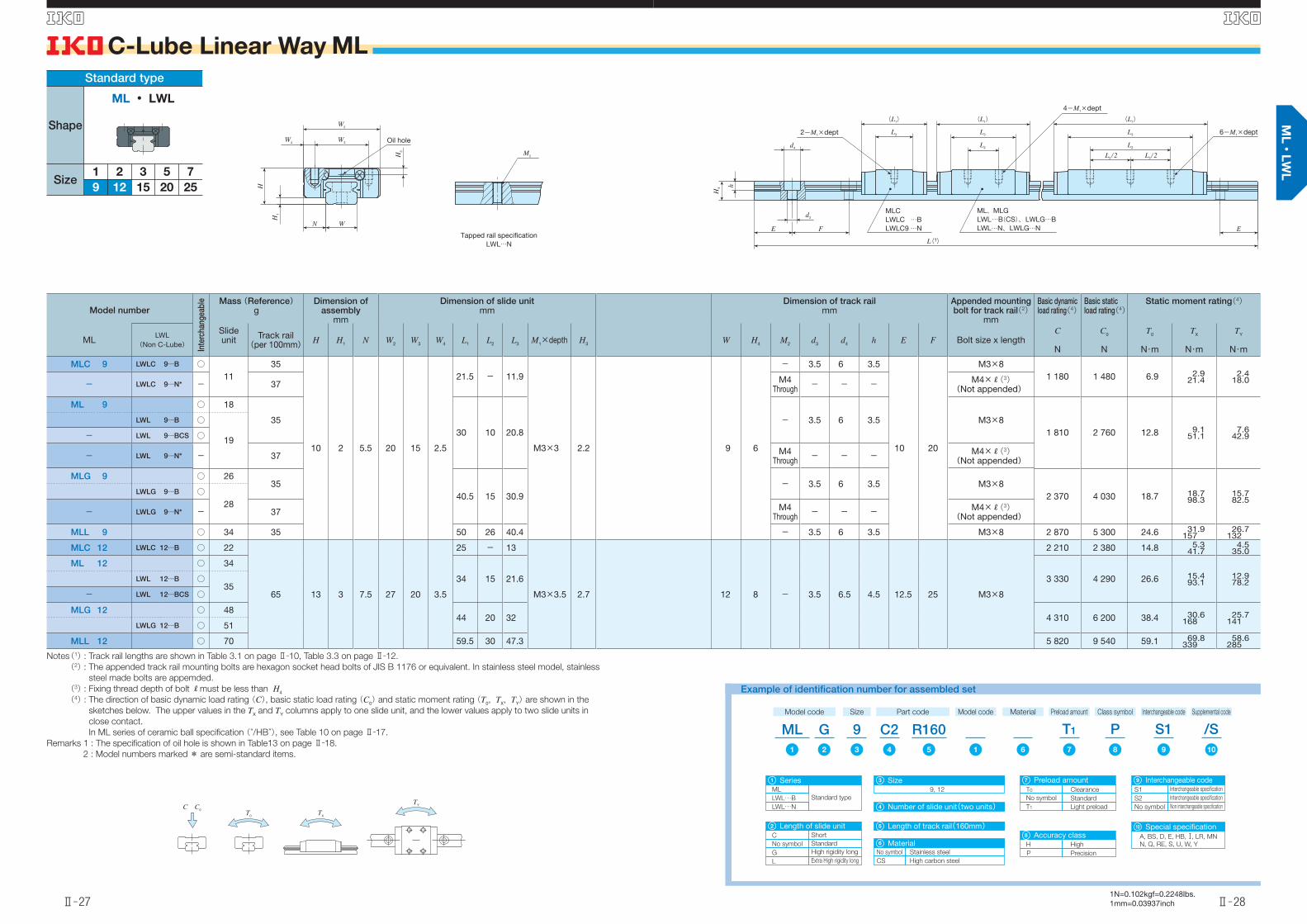
MLC 9 LWLC 9…B ○11
35
10 2 5.5 20 15 2.5
21.5 - 11.9
M3×3 2.2 9 6
- 3.5 6 3.5
10 20
M3×81 180 1 480 6.9 2.9
21.42.4
18.0- LWLC 9…N* - 37 M4Through - - - M4×R(3)
(Not appended)
ML 9 ○ 18
3530 10 20.8
- 3.5 6 3.5 M3×81 810 2 760 12.8 9.1
51.17.6
42.9
LWL 9…B ○
19- LWL 9…BCS ○
- LWL 9…N* - 37 M4Through - - - M4×R(3)
(Not appended)
MLG 9 ○ 2635
40.5 15 30.9- 3.5 6 3.5 M3×8
2 370 4 030 18.7 18.798.3
15.782.5
LWLG 9…B ○28
- LWLG 9…N* - 37 M4Through - - - M4×R(3)
(Not appended)
MLL 9 ○ 34 35 50 26 40.4 - 3.5 6 3.5 M3×8 2 870 5 300 24.6 31.9157
26.7132
MLC 12 LWLC 12…B ○ 22
65 13 3 7.5 27 20 3.5
25 - 13
M3×3.5 2.7 12 8 - 3.5 6.5 4.5 12.5 25 M3×8
2 210 2 380 14.8 5.341.7
4.535.0
ML 12 ○ 34
34 15 21.6 3 330 4 290 26.6 15.493.1
12.978.2LWL 12…B ○
35- LWL 12…BCS ○
MLG 12 ○ 4844 20 32 4 310 6 200 38.4 30.6
16825.7
141LWLG 12…B ○ 51
MLL 12 ○ 70 59.5 30 47.3 5 820 9 540 59.1 69.8339
58.6285
Notes(1) : Track rail lengths are shown in Table 3.1 on page Ⅱ̶10, Table 3.3 on page Ⅱ̶12.
(2) : The appended track rail mounting bolts are hexagon socket head bolts of JIS B 1176 or equivalent. In stainless steel model, stainless
steel made bolts are appemded.
(3) : Fixing thread depth of bolt Rmust be less than H4
(4) : The direction of basic dynamic load rating(C), basic static load rating(C0)and static moment rating(T0, TX, TY)are shown in the
sketches below. The upper values in the TX and TY columns apply to one slide unit, and the lower values apply to two slide units in
close contact.
In ML series of ceramic ball specifi cation(“/HB”), see Table 10 on page Ⅱ̶17.
Remarks 1 : The specifi cation of oil hole is shown in Table13 on page Ⅱ̶18.
2 : Model numbers marked * are semi-standard items.
Example of identification number for assembled set
Model code
MLSize Part code
R160C29G
ML
Standard typeLWL…B
Preload amount Class symbol Supplemental code
T1 /SPInterchangeable code
S1Model code
1 12 87543 109
1
Number of slide unit(two units)4
Size9, 12
3
Length of track rail(160mm)5
S1
Interchangeable code
S2 Interchangeable specification
Interchangeable specification
No symbol Non interchangeable specification
Special specificationA, BS, D, E, HB, , LR, MN
N, Q, RE, S, U, W, Y
Material
6
LWL…N
No symbol Standard
G High rigidity long
L Extra High rigidity long
2
C Short
No symbol
Material
CS High carbon steel
Stainless steel
6
T0
No symbol Standard
Clearance
T1 Light preload
P Precision
H High
Preload amount
Accuracy class
97
8
10
Series
Length of slide unit
Standard type
Shape
Size1 7532
252015129
ML ・ LWL
C C0TXT0
TY
N
W4 W3
W2
W
H
H3
H1
Oil hole
Tapped rail specificationLWL…N
M2
ML、MLGLWL…B(CS)、LWLG…BLWL…N、LWLG…N
MLCLWLC …BLWLC9…N
L(1)
(L1)
L3
(L1)
L3
L2
(L1)
L3
L2
L2/2L2/2
E
2-M1×dept
4-M1×dept
6-M1×dept
d4
d3
E F
H4 h
英_Ⅱ-023-038寸法ML.indd 27-28 11.6.2 5:02:54 PM

Ⅱ̶29
C-Lube Linear Way ML
Ⅱ̶30
1N=0.102kgf=0.2248lbs.1mm=0.03937inch
S S
Model number
Inte
rcha
ngea
ble Mass (Reference)
gDimension of
assemblymm
Dimension of slide unitmm
Dimension of track railmm
Appended mounting bolt for track rail(2)
mm
Basic dynamic load rating(3)
Basic static load rating(3)
Static moment rating(3)
MLLWL
(Non C-Lube)
Slideunit Track rail
(per 100mm) H H1 N W2 W3 W4 L1 L2 L3 L4 M1×depth H3 W H4 d3 d4 h E F Bolt size x lengthC
N
C0
N
T0
N・m
TX
N・m
TY
N・m
MLC 15 ○ 43
107 16 4 8.5 32 25 3.5
32 -17.8
37
M3×4 3.1 15 10 3.5 6.5 4.5 20 40 M3×10
3 490 3 890 30.0 11.784.5
9.870.9LWLC 15…B ○ 42 17.7
ML 15 ○ 63
42 20
27.9
47 4 980 6 490 50.0 29.7172
24.9144LWL 15…B ○
64 27.8- LWL 15…BCS ○
MLG 15 ○ 9357 25
42.862 6 620 9 740 75.0 63.9
33853.6
284LWLG 15…B ○ 95 42.7
MLL 15 ○ 122 72 40 57.7 76 8 370 13 600 105 122585
102491
MLC 20 LWLC 20…B ○ 89
156 20 5 10 40 30 5
38 - 22.3 43
M4×6 4.2 20 11 6 9.5 5.5 30 60 M5×14
4 580 5 300 54.0 19.4134
16.3112
ML 20 ○ 130
50 25 34.6 55 6 650 9 080 92.6 52.7280
44.2235LWL 20…B ○
133- LWL 20…BCS ○
MLG 20 ○ 18968 30 52.3 73 8 510 12 900 131 102
52985.7
444LWLG 20…B ○ 196
MLC 25 ○ 189
243 25 5 12.5 48 35 6.5
54.5 - 31.9 64
M6×7 5 23 15 7 11.0 9.0 30 60 M6×16
9 120 10 600 128 57.4380
48.1319LWLC 25…B ○ 190
ML 25 ○ 30578 35 55.7 88 13 500 18 500 223 163
887137744LWL 25…B ○ 310
MLG 25 ○ 40598 40 75.5 108 16 700 25 200 303 293
1 480246
1 240LWLG 25…B ○ 413
Notes(1) : Track rail lengths are shown in Table 3.1 on page Ⅱ̶10, Table 3.3 on page Ⅱ̶12.
(2) : The appended track rail mounting bolts are hexagon socket head bolts of JIS B 1176 or equivalent. In stainless steel model, stainless
steel made bolts are appemded.
(3) : The direction of basic dynamic load rating(C), basic static load rating(C0)and static moment rating(T0, TX, TY)are shown in the
sketches below. The upper values in the TX and TY columns apply to one slide unit, and the lower values apply to two slide units in
close contact.
In MLC15, ML15, MLG15, and MLL15 of ceramic ball specifi cation(“/HB”), see Table 10 on page Ⅱ̶17.
(4) : The specifi cations of grease nipple are shown in Table 14 on page Ⅱ̶18.
/SP S187 109
T1ML R320C215G1 12 543
Example of identification number for assembled set
Model code Size Part code
MLStandard type
LWL…B
Preload amount Class symbol Supplemental codeInterchangeable codeModel code
Number of slide unit(two units)4
15, 20, 25
Length of track rail(320mm)5
S1
S2 Interchangeable specification
Interchangeable specification
No symbol Non interchangeable specification
A, BS, D, E, HB, , LR, MN
N, Q, RE, S, U, W, Y
6
No symbol Standard
G High rigidity long
L Extra High rigidity long
C Short
No symbol
CS High carbon steel
Stainless steel
T0
No symbol Standard
Clearance
T1 Light preload
P Precision
H High
Series1 Size3 Interchangeable code9
Special specification10Length of slide unit2
Length of track rail6
Preload amount7
Accuracy class8
Material
Standard type
Shape
Size1 7532
252015129
ML ・ LWL
C C0TXT0
TY
N
W4 W3
Grease nipple(4)W2
W
H
H3
H1
MLCLWLC…B
ML、MLGLWL…B(CS)、LWLG…B
L(1)
E
2-M1×depth 6-M1×depth
4-M1×depth
L2/2 L2/2
(L4)
(L1)
E F
d3
d4
H4
h
L3
(L4)
(L1)
L3
L2
(L4)
(L1)
L3
L2
英_Ⅱ-023-038寸法ML.indd 29-30 11.6.2 5:02:56 PM

Ⅱ̶31
C-Lube Linear Way ML
Ⅱ̶32
1N=0.102kgf=0.2248lbs.1mm=0.03937inch
S S
Model number
Inte
rcha
ngea
ble Mass (Reference)
gDimension of
assemblymm
Dimension of slide unitmm
Dimension of track railmm
Appended mounting bolt for track rail(3)
mm
Basic dynamic load rating(5)
Basic static load rating(5)
Static moment rating(5)
MLFLWLF
(Non C-Lube)
Slideunit Track rail
(per 100mm) H H1 N W2 W3 W4 L1 L2 L3 M1×depth H3 W H4 M2 d3 d4 h E F Bolt size x lengthC
N
C0
N
T0
N・m
TX
N・m
TY
N・m
- LWLF 4(2) - 2.1 6.8 4 1 3 10 - 5 17 6.5 11.9 M2 × 1.3 - 4 2.6 - 1.8 2.8 0.75 5 10 Cross-recessed head cap screw for precision equipmentM1.6×5 390 677 1.4 1.3
7.11.58.4
- LWLFC 6(2) -2.4
13
4.5 1 3 12 - 6
15 4.5 9.8
M2 × 1.6 - 6 2.8
- 2.4 4 1.5
7.5 15
Cross-recessed head cap screw for precision equipmentM2×4
334 542 1.7 0.845.1
1.06.1
- LWLFC 6…N(2)* - 12 M3Through - - - M3×R(4)
(Not appended)
- LWLF 6(2) -3.4
1320 8 14.6
- 2.4 4 1.5 Cross-recessed head cap screw for precision equipmentM2×4
443 813 2.5 1.89.9
2.211.8
- LWLF 6…N(2)* - 12 M3Through - - - M3×R(4)
(Not appended)
MLFC 10 ○ 6.128
6.5 1.5 3.5 17 13 2
20.5
-
13.6
M2.5×1.5 1.3 10 4
- 2.9 4.8 1.6
10 20
Cross-recessed head cap screw for precision equipmentM2.5×7
712 1 180 6.1 2.614.9
2.212.5
LWLFC 10…B ○5.9
- LWLFC 10…N* - 29 M3Through - - - M3×R(4)
(Not appended)
MLF 10 ○ 7.628
24.5 17.6- 2.9 4.8 1.6 Cross-recessed head cap screw for precision equipment
M2.5×7849 1 510 7.8 4.2
22.43.5
18.8LWLF 10…B ○
7.5- LWLF 10…N* - 29 M3
Through - - - M3×R(4)(Not appended)
Notes(1) : Track rail lengths are shown in Table 3.2 on page Ⅱ̶11.
(2) : Size 4 and 6 are ball non-retained type. They are provided without end seals.
(3) : The appended track rail mounting bolts are hexagon socket head bolts of JIS B 1176 or equivalent. In stainless steel model, stainless
steel made bolts are appemded.
(4) : Fixing thread depth of bolt Rmust be less than H4
(5) : The direction of basic dynamic load rating(C), basic static load rating(C0)and static moment rating(T0, TX, TY)are shown in the
sketches below. The upper values in the TX and TY columns apply to one slide unit, and the lower values apply to two slide units in
close contact.
(6) : No oil hole is prepared for size 4 and 6.
The specifi cation of oil hole size 10 is shown in Table13 on page Ⅱ̶18.
Remark : Model numbers marked * are semi-standard items.
Example of identification number for assembled setExample of identification number for assembled set
Model code
MLFSize Part code
R120C210
MLF
Series
Wide typeLWLF(…B)
Preload amount Class symbol Supplemental code
T0 /SPModel code
1 12 76543 9
1
Number of slide unit(two units)4
Size4, 6, 10
3
Length of track rail(120mm)5
No symbol
Length of slide unit
Standard
2
C Short
LWLF…N
CInterchangeable code
S18
S1
Interchangeable code
S2 Interchangeable specification
Interchangeable specification
No symbol Non interchangeable specification
8
T0
Preload amount
No symbol Standard
Clearance
6
P
Accuracy class
Precision
7
H High
Special specificationA, BS, D, E, , MN, N, Q
RE, S, W, Y
9
Wide type
Shape
Size4 14106
302418 42
MLF ・ LWLF
C C0
TXT0
TY
W2
W3W4
WN
H3
H
H1
Oil hole(6)
Tapped rail specificationLWLF…N
M2
(L1)
L3
(L1)
L3
FE
L2
MLFC 10、MLF10LWLFC10…B、LWLF10…BLWLFC10…N、LWLF10…N E
2-M1×depth
L(1)
d4
d4
H4 h
2-M1×depth
英_Ⅱ-023-038寸法ML.indd 31-32 11.6.2 5:02:57 PM

Ⅱ̶33
C-Lube Linear Way ML
Ⅱ̶34
1N=0.102kgf=0.2248lbs.1mm=0.03937inch
S S
Model number
Inte
rcha
ngea
ble Mass (Reference)
gDimension of
assemblymm
Dimension of slide unitmm
Dimension of track railmm
Appended mounting bolt for track rail(2)
mm
Basic dynamic load rating(4)
Basic static load rating(4)
Static moment rating(4)
MLFLWLF
(Non C-Lube)
Slideunit Track rail
(per 100mm) H H1 N W2 W3 W4 L1 L2 L3 M1×depth H3 W H4 M2 d3 d4 h E F Bolt size x lengthC
N
C0
N
T0
N・m
TX
N・m
TY
N・m
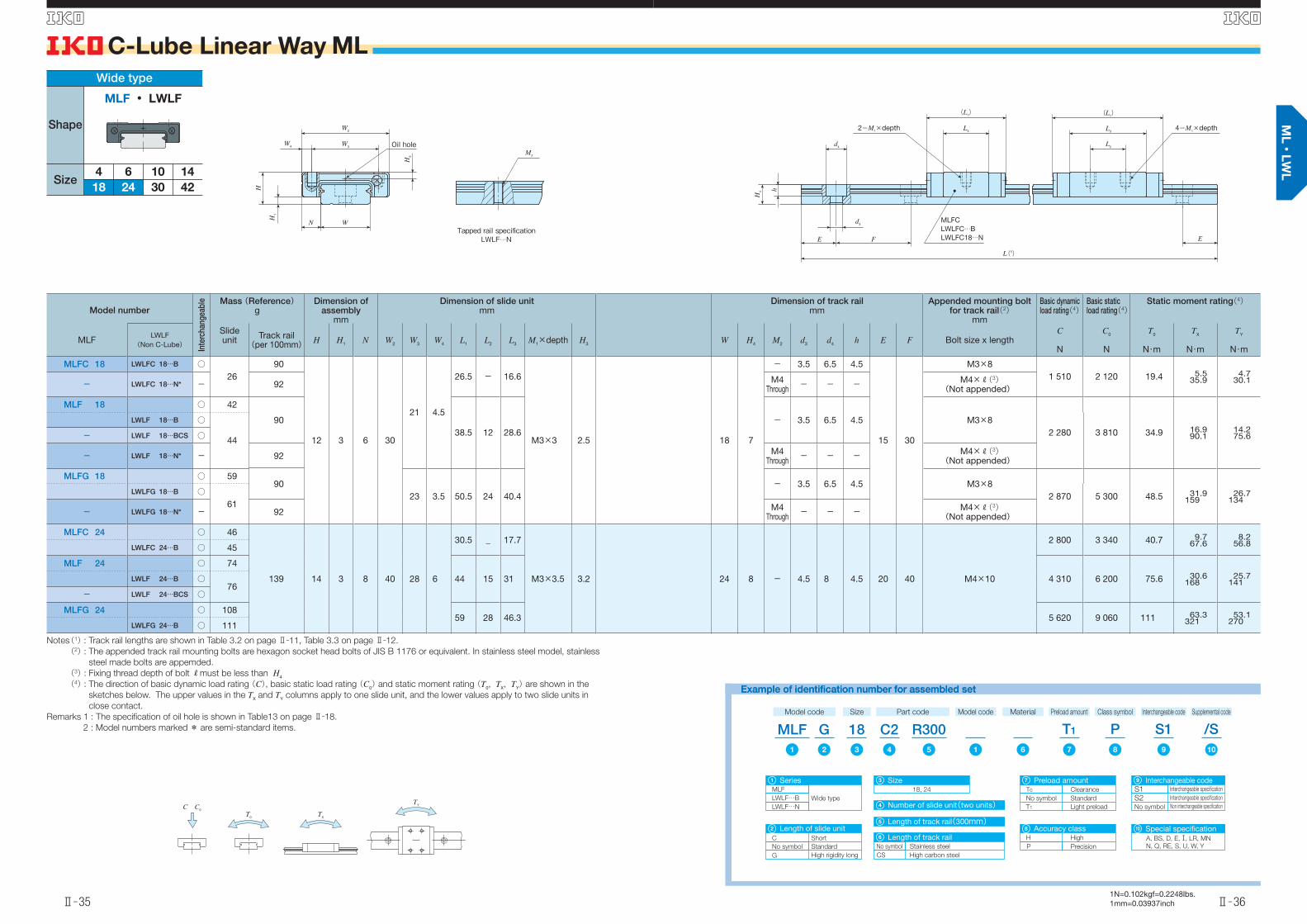
MLFC 14 LWLFC 14…B ○13
54
9 2 5.5 25 19 3
22.5 - 13
M3×3 1.7 14 5.5
- 3.5 6 3.2
15 30
M3×81 240 1 700 12.2 3.8
24.63.2
20.7- LWLFC 14…N* - 56 M4Through - - - M4×R(3)
(Not appended)
MLF 14 ○ 2054
31.5 10 22- 3.5 6 3.2 M3×8
1 770 2 840 20.3 10.154.7
8.445.9
LWLF 14…B ○21
- LWLF 14…N* - 56 M4Through - - - M4×R(3)
(Not appended)
MLFG 14 ○ 2954
42 19 32.5- 3.5 6 3.2 M3×8
2 320 4 160 29.8 21.0104
17.687.6
LWLFG 14…B ○31
- LWLFG 14…N* - 56 M4Through - - - M4×R(3)
(Not appended)
Notes(1) : Track rail lengths are shown in Table 3.2 on page Ⅱ̶11.
(2) : The appended track rail mounting bolts are hexagon socket head bolts of JIS B 1176 or equivalent. In stainless steel model, stainless
steel made bolts are appemded.
(3) : Fixing thread depth of bolt Rmust be less than H4
(4) : The direction of basic dynamic load rating(C), basic static load rating(C0)and static moment rating(T0, TX, TY)are shown in the
sketches below. The upper values in the TX and TY columns apply to one slide unit, and the lower values apply to two slide units in
close contact.
Remarks 1 : The specifi cation of oil hole is shown in Table13 on page Ⅱ̶18.
2 : Model numbers marked * are semi-standard items.
Example of identification number for assembled setExample of identification number for assembled set
Model code
MLFSize Part code
R240C214
MLF
Series
Wide typeLWLF…B
Preload amount Class symbol Supplemental code
T1 /SPModel code
1 12 76543 9
1
Number of slide unit(two units)4
Size14
3
Length of track rail(240mm)5
LWLF…N
GInterchangeable code
S18
S1
Interchangeable code
S2 Interchangeable specification
Interchangeable specification
No symbol Non interchangeable specification
8
T0
Preload amount
No symbol Standard
Clearance
T1 Light preload
6
P
Accuracy class
Precision
7
H High
Special specificationA, BS, D, E, , LR, MN
N, Q, RE, S, W, Y
9
No symbol
Length of slide unit
Standard
G High rigidity long
2
C Short
Wide type
Shape
Size4 14106
302418 42
MLF ・ LWLF
C C0
TXT0
TY
W2
W3W4
WN
H3
H
H1
Oil hole
Tapped rail specificationLWLF…N
M2
(L1)
L3
(L1)
L3
FE
L2
MLFC14LWLFC14…BLWLFC14…N E
4-M1×depth
L(1)
d4
d3
H4 h
2-M1×depth
英_Ⅱ-023-038寸法ML.indd 33-34 11.6.2 5:02:59 PM
Ⅱ̶35
C-Lube Linear Way ML
Ⅱ̶36
1N=0.102kgf=0.2248lbs.1mm=0.03937inch
S S
Model number
Inte
rcha
ngea
ble Mass (Reference)
gDimension of
assemblymm
Dimension of slide unitmm
Dimension of track railmm
Appended mounting bolt for track rail(2)
mm
Basic dynamic load rating(4)
Basic static load rating(4)
Static moment rating(4)
MLFLWLF
(Non C-Lube)
Slideunit Track rail
(per 100mm) H H1 N W2 W3 W4 L1 L2 L3 M1×depth H3 W H4 M2 d3 d4 h E F Bolt size x lengthC
N
C0
N
T0
N・m
TX
N・m
TY
N・m
MLFC 18 LWLFC 18…B ○26
90
12 3 6 30
21 4.5
26.5 - 16.6
M3×3 2.5 18 7
- 3.5 6.5 4.5
15 30
M3×81 510 2 120 19.4 5.5
35.94.7
30.1- LWLFC 18…N* - 92 M4Through - - - M4×R(3)
(Not appended)
MLF 18 ○ 42
9038.5 12 28.6
- 3.5 6.5 4.5 M3×82 280 3 810 34.9 16.9
90.114.275.6
LWLF 18…B ○
44- LWLF 18…BCS ○
- LWLF 18…N* - 92 M4Through - - - M4×R(3)
(Not appended)
MLFG 18 ○ 5990
23 3.5 50.5 24 40.4- 3.5 6.5 4.5 M3×8
2 870 5 300 48.5 31.9159
26.7134
LWLFG 18…B ○61
- LWLFG 18…N* - 92 M4Through - - - M4×R(3)
(Not appended)
MLFC 24 ○ 46
139 14 3 8 40 28 6
30.5 _ 17.7
M3×3.5 3.2 24 8 - 4.5 8 4.5 20 40 M4×10
2 800 3 340 40.7 9.767.6
8.256.8LWLFC 24…B ○ 45
MLF 24 ○ 74
44 15 31 4 310 6 200 75.6 30.6168
25.7141LWLF 24…B ○
76- LWLF 24…BCS ○
MLFG 24 ○ 10859 28 46.3 5 620 9 060 111 63.3
32153.1
270LWLFG 24…B ○ 111
Notes(1) : Track rail lengths are shown in Table 3.2 on page Ⅱ̶11, Table 3.3 on page Ⅱ̶12.
(2) : The appended track rail mounting bolts are hexagon socket head bolts of JIS B 1176 or equivalent. In stainless steel model, stainless
steel made bolts are appemded.
(3) : Fixing thread depth of bolt Rmust be less than H4
(4) : The direction of basic dynamic load rating(C), basic static load rating(C0)and static moment rating(T0, TX, TY)are shown in the
sketches below. The upper values in the TX and TY columns apply to one slide unit, and the lower values apply to two slide units in
close contact.
Remarks 1 : The specifi cation of oil hole is shown in Table13 on page Ⅱ̶18.
2 : Model numbers marked * are semi-standard items.
Example of identification number for assembled setExample of identification number for assembled set
Model code
MLFSize Part code
R300C218GPreload amount Class symbol Supplemental code
T1 /SPInterchangeable code
S1Model code
1 12 87543 109
Material
6
MLF
Series
Wide typeLWLF…B
1
Number of slide unit(two units)4
Size18, 24
3
Length of track rail(300mm)5
LWLF…N
S1
Interchangeable code
S2 Interchangeable specification
Interchangeable specification
No symbol Non interchangeable specification
9
T0
Preload amount
No symbol Standard
Clearance
T1 Light preload
7
P
Accuracy class
Precision
8
H High
Special specificationA, BS, D, E, , LR, MN
N, Q, RE, S, U, W, Y
10
No symbol
Length of slide unit
Standard
G High rigidity long
2
C Short
No symbol
Length of track rail
CS High carbon steel
Stainless steel
6
Wide type
Shape
Size4 14106
302418 42
MLF ・ LWLF
C C0
TXT0
TY
W2
W3W4
WN
H3
H
H1
Oil hole
Tapped rail specificationLWLF…N
M2
(L1)
L3
(L1)
L3
FE
L2
MLFCLWLFC…BLWLFC18…N E
4-M1×depth
L(1)
d4
d3
H4 h
2-M1×depth
英_Ⅱ-023-038寸法ML.indd 35-36 11.6.2 5:03:00 PM

Ⅱ̶37
C-Lube Linear Way ML
Ⅱ̶38
1N=0.102kgf=0.2248lbs.1mm=0.03937inch
S S
Model number
Inte
rcha
ngea
ble Mass (Reference)
gDimension of
assemblymm
Dimension of slide unitmm
Dimension of track railmm
Appended mounting bolt for track rail(2)
mm
Basic dynamic load rating(3)
Basic static load rating(3)
Static moment rating(3)
MLFLWLF
(Non C-Lube)
Slideunit Track rail
(per 100mm) H H1 N W2 W3 W4 L1 L2 L3 L4 M1×depth H3 W H4 W5 W6 d3 d4 h E F Bolt size x lengthC
N
C0
N
T0
N・m
TX
N・m
TY
N・m
MLFC 30 LWLFC 30…B ○ 70
198 15 3 10 50 35 7.5
35.5 - 20.5 40
M4×4.5 3.1 30 9 - - 4.5 8 4.5 20 40 M4×12
3 890 4 540 69.1 15.4107
13.089.9
MLF 30 ○ 111
49.5 18 34.8 54 5 970 8 440 128 48.7259
40.8217
LWLF 30…B ○112
- LWLF 30…BCS ○
MLFG 30 ○ 16768.5 35 53.8 73 7 810 12 300 187 100
50884.3
426LWLFG 30…B ○ 170
MLFC 42 ○95
294 16 4 9 60 45 7.5
41.5 -25.7
46
M4×4.5 3.2 42 10 23 9.5 4.5 8 4.5 20 40 M4×12
5 440 6 810 144 30.8180
25.8151
LWLFC 42…B ○ 25.3 5 030 6 050 128 24.8164
20.8137
MLF 42 ○ 138
55 20
39.4
60 7 050 9 840 209 61.3333
51.4280
LWLF 42…B ○140 39
- LWLF 42…BCS ○
MLFG 42 ○ 20074.5 35
58.779
9 520 15 100 321 140674
117565
LWLFG 42…B ○ 204 58.3 9 200 14 400 305 126644
106541
Notes(1) : Track rail lengths are shown in Table 3.2 on page Ⅱ̶11, Table 3.3 on page Ⅱ̶12.
(2) : The appended track rail mounting bolts are hexagon socket head bolts of JIS B 1176 or equivalent. In stainless steel model, stainless
steel made bolts are appemded.
(3) : The direction of basic dynamic load rating(C), basic static load rating(C0)and static moment rating(T0, TX, TY)are shown in the
sketches below. The upper values in the TX and TY columns apply to one slide unit, and the lower values apply to two slide units in
close contact.
Remark : The specifi cations of grease nipple are shown in Table14 on page Ⅱ̶18.
Example of identification number for assembled set
Model code
MLFSize Part code
R320C242GPreload amount Class symbol Supplemental code
T1 /SPInterchangeable code
S1Model code
1 12 87543 109
Material
6
MLF
Series
Wide typeLWLF…B
1
Number of slide unit(two units)4
Size30, 42
3
Length of track rail(320mm)5
S1
Interchangeable code
S2 Interchangeable specification
Interchangeable specification
No symbol Non interchangeable specification
9
T0
Preload amount
No symbol Standard
Clearance
T1 Light preload
7
P
Accuracy class
Precision
8
H High
Special specificationA, BS, D, E, , LR, MN
N, Q, RE, S, U, W, Y
10
No symbol
Length of slide unit
Standard
G High rigidity long
2
C Short
No symbol
Length of track rail
CS High carbon steel
Stainless steel
6
Wide type
Shape
Size4 14106
302418 42
MLF ・ LWLF
C C0
TXT0
TY
MLFC 42, LWLFC 42…BMLF 42, LWLF 42…B(CS)MLFG 42, LWLFG 42…B
W2
W3
W5W6
W2
WN
W4W3
WN
W4
H
H1
H3
H3
H
H1
L3 L3
L2
EE F
H4
L(1)
(L1)
(L4)
(L1)
(L4)
d4
d3
h
2-M1×depth 4-M1×depth
MLFCLWLFC…B
Grease nipple Grease nipple
英_Ⅱ-023-038寸法ML.indd 37-38 11.6.2 5:03:02 PM