burndy products substation - eversavetech.net20l...throughout the catalog you will notice blue...
TRANSCRIPT

BURNDY® Products Substation — Bolted
US: 1-800-346-4175 www.burndy.com Canada: 1-800-387-6487
Throughout the catalog you will notice blue highlighted items. These are the most frequently ordered BURNDY® Products.
L-1
COPPER SUBSTATIONIntroduction . . . . . . . . . . . . . . . L-3
Type NTTube to Tube . . . . . . . . . . . . . . L-4
Type NSNT/NHNTTube to Cable . . . . . . . . . . . . . L-5
Type NSNT/NHNTCable to Cable . . . . . . . . . . . . L-6
Type VTCable to Cable . . . . . . . . . . . . L-7
Type NSTube to Tube . . . . . . . . . . . . . . L-7
Type XPTube to Tube . . . . . . . . . . . . . . L-8
Type BFlexible Braid Jumper. . L-8 - L-11
Type B Assembly ComponentsExpansion Coupler . . . . . . . . L-12
Type HFBWBar Clamp . . . . . . . . . . . . . . . L-13
Type HFB-P1Bar Clamp . . . . . . . . . . . . . . . L-14
Type HFB-NTap Pad Adapter . . . . . . . . . . L-15
Type NATube to Flat . . . . . . . . . . . . . . L-16
Type XATube to Flat, Expandable. . . . L-16
Type NAS/NAHCable to Flat (Terminal) . . . . . L-17
Type N2AHTwo Cables to Flat . . . . . . . . . L-18
Type VA, VVACable to Flat (Terminal) . . . . . L-19
Type UHBus Support, Tube. . . . . . . . . L-20
TABLE OF CONTENTS
W
H
J L
T
B
U

Substation — Bolted BURNDY® Products
Canada: 1-800-387-6487 www.burndy.com US: 1-800-346-4175
Throughout the catalog you will notice blue highlighted items. These are the most frequently ordered BURNDY® Products.
L-2
Type UHRBus Support, Tube or Cable . L-20
Types LH, LHRBus Support, Tube or Cable . L-21
Type NDRStud Connector, Cable, Tube, Flat Bar. . . . . . . . . . . . L-22
Type FDStud Connector, Stud to Flat Bar. . . . . . . . . . . . . . . . . L-23
Type QGFLBar Tap, Cable to Flat . . . . . . L-24
Type FCBTransformer Tap Adapter . . . . L-24
Type E-C-GTransformer Tap Adapter . . . . L-25
Type FN . . . . . . . . . . . . . . . . L-25
ALUMINUM SUBSTATIONIntroduction . . . . . . . . . . . . . . L-26
Type NNT-ATube to Tube . . . . . . . . . . . . . L-27
Type NNTR-ATube to Cable, Cable to Cable... . . . . . . . . . . . . L-27 - L-28
Type NS-ATube to Tube . . . . . . . . . . . . . L-28
Type NA-ATube to Flat . . . . . . . . . . . . . . L-29
Type XA-ATube to Flat . . . . . . . . . . . . . . L-29
Type NBC-ATube to Flat . . . . . . . . . . . . . . L-30
Type NAR-ACable to Flat . . . . . . . . . . . . . L-31
Type UHG-ABus Support, Tube. . . . . . . . . L-32
Type UHKR-ABus Support, Tube or Cable . L-32
Type LB-AEnd Cap, Aluminum Tube . . . L-33
Type WAS-ATerminal Connector . . . . . . . . L-34
Type WASC-A-NCenterformed Terminal . . . . . L-35
Type WG-AWeldment Ground Stud . . . . . L-36
TABLE OF CONTENTS (Continued)

BURNDY® Products Substation — Bolted
US: 1-800-346-4175 www.burndy.com Canada: 1-800-387-6487
Throughout the catalog you will notice blue highlighted items. These are the most frequently ordered BURNDY® Products.
L-3
COPPERSUBSTATION CONNECTORS
INTRODUCTION
BURNDY® electrical connectors aredesigned to be installed with a minimum ofeffort, to run cooler than the conductorsbeing joined and to provide optimum per-formance under all operating conditions.
To achieve this type of performance, exten-sive research and development time is spentby BURNDY® engineers and scientists toimprove manufacturing techniques, materialsand designs. As these improvements becomeavailable, they are incorporated into bothexisting and new product lines. This continu-ous program of product innovation andimprovement insures that, as new and morecritical applications evolve, high quality con-nectors from BURNDY® will be available to meet the need.
Flat pad connectors used to join cable or tubing terminals to equipment studs.
A variety of bus supports are also availablefor tube or cable. Some can be adjusted foreither a rigid or slide-fit by rotating theclamping cap 180°.
Expansion connectors are used to absorbthe stress imposed on the bus by settlingground, thermal expansion and shocks, as incircuit breaker operations. The flexible ele-ments are flat-tinned, copper braid, with suf-ficient cross sectional area to carry the ratedcurrent of the conductors being joined.
N-Line connectors are two-piece copperalloy castings assembled with DURIUM™(silicon bronze) hex bolts, nuts and washers.They are available for connecting tube orcable.
The Variline incorporates a modified V-bolt asthe clamping element for heavy-duty appli-cations. This line is particularly suited for usewith flexible and extra flexible cables.

Substation — Bolted BURNDY® Products
Canada: 1-800-387-6487 www.burndy.com US: 1-800-346-4175
Throughout the catalog you will notice blue highlighted items. These are the most frequently ordered BURNDY® Products.
L-4
TYPE NT
T-CONNECTOR
FOR COPPER TUBE TO TUBE
High copper alloy T-Connector for tubing runand tap. Slots between bolts provide inde-pendent high-pressure areas of contact. One-wrench installation.
Catalog ConductorNumber Run ‘A’ Tap ‘AA’ B H J LNT1414 3/4 3/4 2 4-1/8NT1514 1 3/4 4-3/8NT1515 1 1 2 2-1/8 3/8 4-1/2NT1614 3/4NT1615 1-1/4 1
2-1/2 4-3/4
NT1616 1-1/4 2-3/4 2-5/8 1/2 5-3/4NT1714 3/4 2 3/8 5-1/8NT1717
1-1/21-1/2 2-3/4
2-3/46-1/8
NT1818 2 2 3-1/8 3-3/8 1/2 6-3/4NT2020 3 3 4-3/8 4-5/8 8-5/8NT2222 4 4 5-1/2 5-3/4 5/8 9-7/8

BURNDY® Products Substation — Bolted
US: 1-800-346-4175 www.burndy.com Canada: 1-800-387-6487
Throughout the catalog you will notice blue highlighted items. These are the most frequently ordered BURNDY® Products.
L-5
TYPE NSNT/NHNT
T-CONNECTOR
FOR COPPER TUBETO CABLE
High copper alloy T-Connector for joiningcopper tubing run to a wide range of coppertap cable. Tap utilizes reversible cap toachieve large conductor range and the con-nector is designed for one-wrench installa-tion.
① Complete cable range may be accommodated by reversingcap.
Run Commercial Copper Cable RangeIPS Complete ➀ Small Large
Catalog or Tap Cable Tap Tap “J”Number EHPS A Range AA Groove Groove B B-B H Dia. L W YNSNT1329 6 Sol. (.162 Dia.) to 6 Sol. (.162 Dia.) to 2/0 Str. (.420 Dia.) to 2.00 2.38 2.00 3/8�-16 5.08 1.96 3.89NHNT1329
1/2� (.840 Dia.)250 kcmil (.575 Dia.) 1/0 Str. (.372 Dia.) 250 kcmil (.575 Dia.) 2.25 2.62 2.32 1/2�-13 5.82 2.44 4.38
NSNT1429 6 Sol. (.162 Dia.) to 6 Sol. (.162 Dia.) to 2/0 Str. (.420 Dia.) to 2.00 2.38 2.00 3/8�-16 5.08 1.96 3.89NHNT1429 250 kcmil (.575 Dia.) 1/0 Str. (.372 Dia.) 250 kcmil (.575 Dia.) 2.25 2.62 2.32 1/2�-13 5.82 2.44 4.38NSNT1434
3/4� (1.050 Dia.)1/0 Sol. (.325 Dia.) to 1/0 Sol. (.325 Dia.) to 250 kcmil (.575 Dia.) to 2.00 2.38 2.10 3/8�-16 5.08 2.20 3.89
NHNT1434 500 kcmil (.813 Dia.) 4/0 Str. (.529 Dia.) 500 kcmil (.813 Dia.) 2.25 2.62 2.42 1/2�-13 5.82 2.56 4.38NSNT1529 6 Sol. (.162 Dia.) to 6 Sol. (.162 Dia.) to 2/0 Str. (.420 Dia.) to 2.00 2.38 2.00 3/8�-16 5.34 1.96 4.02NHNT1529 250 kcmil (.575 Dia.) 1/0 Str. (.372 Dia.) 250 kcmil (.575 Dia.) 2.57 2.44
1/0 Sol. (.325 Dia.) to 1/0 Sol. (.325 Dia.) to 250 kcmil (.575 Dia.) to 5.92NHNT1534 1� (1.315 Dia.)
500 kcmil (.813 Dia.) 4/0 Str. (.529 Dia.) 500 kcmil (.813 Dia.) 2.25 2.622.57
1/2�-132.56
4.432/0 Str. (.420 Dia.) to 2/0 Str. (.420 Dia.) to 500 kcmil (.813 Dia.) to
NHNT1540800 kcmil (1.031 Dia.) 500 kcmil (.813 Dia.) 800 kcmil (1.03 Dia.)
2.60 — 2.78
NSNT1629 6 Sol. (1.62 Dia.) to 6 Sol (.162 Dia.) to 2/0 Str. (.420 Dia.) to 2.00 2.38 2.37 3/8�-16 5.78 1.96 4.24NHNT1629 250 kcmil (.575 Dia.) to 1/0 Str. (.372 Dia.) 250 kcmil (.575 Dia.) 2.57 2.44
1/0 Sol. (.325 Dia.) to 1/0 Sol. (.325 Dia.) to 250 kcmil (.575 Dia.) toNHNT1634
500 kcmil (.813 Dia.) 4/0 Str. (.529 Dia.) 500 kcmil (.813 Dia.) 2.622.60
6.322.56
4.631-1/4� (1.660 Dia.)
2/0 Str. (.420 Dia.) to 2/0 Str. (.420 Dia.) to 500 kcmil (.813 Dia.) to 2.69NHNT1640
800 kcmil (1.031 Dia.) 500 kcmil (.813 Dia.) 800 kcmil (1.031 Dia.)2.68 2.78
4/0 Str. (.529 Dia.) to 4/0 Str. (.529 Dia.) to 750 kcmil (.998 Dia.) toNHNT1644
1000 kcmil (1.152 Dia.) 750 kcmil (.998 Dia.) 1000 kcmil (1.152 Dia.)2.88 2.69 6.58 2.90 4.89
6 Sol. (.162 Dia.) to 6 Sol. (.162 Dia.) to 210 Str. (.420 Dia.) toNHNT1729
250 kcmil (.575 Dia.) 1/0 Str. (.372 Dia.) 250 kcmil (.575 Dia.)2.70 2.44
1/0 Sol. (.325 Dia.) to 1/0 Sol. (.325 Dia.) to 250 kcmil (.575 Dia.) toNHNT1734
500 kcmil (.813 Dia.) 4/0 Str. (.529 Dia.) 500 kcmil (.813 Dia.)2.62 2.70 6.76 2.56 4.85
1-1/2� (1.900 Dia.)2/0 Str. (.420 Dia.) to 2/0 Str. (.420 Dia.) to 500 kcmil (.813 Dia.) to
2.69NHNT1740
800 kcmil (1.031 Dia.) 500 kcmil (.813 Dia.) 800 kcmil (1.031 Dia.)2.78 2.78
4/0 Str. (.529 Dia.) to 4/0 Str. (.529 Dia.) to 750 kcmil (.998 Dia.) toNHNT1744
1000 kcmil (1.152 Dia.) 750 kcmil (.998 Dia.) 1000 kcmil (1.152 Dia.)2.88 2.80 7.02 2.90 5.11
6 Sol. (.162 Dia.) to 6 Sol. (.162 Dia.) to 2/0 Str. (.420 Dia.) toNHNT1829
250 kcmil (.575 Dia.) 1/0 Str. (.372 Dia.) 250 kcmil (.575 Dia.)2.44
1/0 Sol. (.325 Dia.) to 1/0 Sol. (.325 Dia.) to 250 kcmil (.575 Dia.) toNHNT1834
500 kcmil (.813 Dia.) 4/0 Str. (.529 Dia.) 500 kcmil (.813 Dia.)2.62 3.06
1/2�-137.44 2.56 5.19
2/0 Str. (.420 Dia.) to 2/0 Str. (.420 Dia.) to 500 kcmil (.813 Dia.)NHNT1840 2� (2.375 Dia.)
800 kcmil (1.031 Dia.) 500 kcmil (.813 Dia.) 800 kcmil (1.031 Dia.)2.69 2.78
4/0 Str. (.529 Dia.) to 4/0 Str. (.529 Dia.) to 750 kcmil (.998 Dia.) toNHNT1844
1000 kcmil (1.152 Dia.) 750 kcmil (.998 Dia.) 1000 kcmil (1.152 Dia.)2.88 3.06 7.70 2.90 5.45
1000 kcmil (1.152 Dia.) to 1000 kcmil (1.152 Dia.) toNHNT1846
1500 kcmil (1.412 Dia.)—
1500 kcmil (1.412 Dia.)3.06 3.23 7.88 3.16 5.63
6 Sol. (.162 Dia.) to 6 Sol. (.162 Dia.) to 2/0 Str. (.420 Dia.) toNHNT1929
250 kcmil (.575 Dia.) 1/0 Str. (.372 Dia.) 250 kcmil (.575 Dia.)2.44
1/0 Sol. (.325 Dia.) to 1/0 Sol. (.325 Dia.) to 250 kcmil (.575 Dia.) toNHNT1934
500 kcmil (.813 Dia.) 4/0 Str. (.529 Dia.) 500 kcmil (.813 Dia.)2.62 8.06 2.56 5.50
2/0 Str. (.420 Dia.) to 2/0 Str. (.420 Dia.) to 500 kcmil (.813 Dia.) toNHNT1940 2-1/2� (2.875 Dia.)
800 kcmil (1.031 Dia.) 500 kcmil (.813 Dia.) 800 kcmil (1.031 Dia.)3.64 2.78
4/0 Str. (.529 Dia.) to 4/0 Str. (.529 Dia.) to 750 kcmil (.998 Dia.) to2.69
NHNT19441000 kcmil (1.152 Dia.) 750 kcmil (.998 Dia.) 1000 kcmil (1.152 Dia.)
2.88 8.32 2.90 5.76
1000 kcmil (1.152 Dia.) to 1000 kcmil (1.152 Dia.) toNHNT1946
1500 kcmil (1.412 Dia.)—
1500 kcmil (1.412 Dia.)3.06 8.50 3.16 5.94
4/0 Str. (.529 Dia.) to 4/0 Str. (.529 Dia.) to 750 kcmil (.998 Dia.) toNHNT2044 3� (3.500 Dia.) 1000 kcmil (1.152 Dia.) 750 kcmil (.998 Dia.) 1000 kcmil (1.152 Dia.)
5.75 4.26 8.95 2.90 6.07

Substation — Bolted BURNDY® Products
Canada: 1-800-387-6487 www.burndy.com US: 1-800-346-4175
L-6
TYPE NSNT/NHNT
T-CONNECTOR
FOR COPPER CABLE TO CABLE
High copper alloy reversible T-Connector forjoining a wide range of run and tap cables.Connector is designed for one-wrench instal-lation. “S” standard 3/8� hardware and “H” heavy duty 1/2� hardware.
CatalogNumber B B-B H “J” DIA. L W YNSNT2929 2.38 2.38 1.75 3/8�-16 4.60 1.96 3.62NHNT2929 2.62 2.62 2.07 1/2�-13 5.32 2.44 4.10NSNT3429 2.38 2.38 2.00 3/8�-16 4.84 1.96 3.74NHNT3429 2.62 2.62 2.32 1/2�-13 5.44 2.44 4.16NSNT3434 2.38 2.38 2.00 3/8�-16 4.84 2.20 3.74NHNT3434 2.62 2.62 2.32 5.38 2.56 4.10NHNT4429 2.44NHNT4434 2.62 5.78 2.56 4.33NHNT4440
2.88 2.572.78
NHNT4444 2.88 6.03 2.90 4.58NHNT4834
1/2�-132.56
NHNT4840 2.626.26
2.784.57
NHNT4844 3.25 2.88 3.07 6.51 2.90 4.82NHNT4846 3.06 6.76 3.16 5.07NHNT4848 3.25 6.94 3.38 5.25
Commercial Copper Cable RangeComplete CompleteRun Cable Small Large Tap Cable Small Large
Catalog Range Run Run Range Tap TapNumber A ➀ Groove Groove AA ➀ Groove Groove
6 Sol. (.162 Dia.) 6 Sol. (.162 Dia.) 2/0 Str. (.420 Dia.)NSNT2929to 250 kcmil to 1/0 Str. to 250 kcmil
6 Sol. (.162 Dia.) 6 Sol. (.162 Dia.) 2/0 Str. (.420 Dia.)
NHNT2929 (.575 Dia.) (.372 Dia.) (.575 Dia.)to 250 kcmil to 1/0 Str. to 250 kcmil
NSNT3429 1/0 Sol. 1/0 Sol. 250 kcmil(.575 Dia.) (.372 Dia.) (.575 Dia.)
NHNT3429 (.325 Dia.) (.325 Dia.) (.575 Dia.) 1/0 Sol. (.325 Dia.) 1/0 Sol. (.325 Dia.) 250 kcmil (.575 Dia.)NSNT3434 to 500 kcmil to 4/0 Str. to 500 kcmil to 500 kcmil to 4/0 Str. to 500 kcmilNHNT3434 (.813 Dia.) (.529 Dia.) (.813 Dia.) (.813 Dia.) (.529 Dia.) (.813 Dia.)
6 Sol. (.162 Dia.) 6 Sol. (.162 Dia.) 2/0 Str. (.420 Dia.)NHNT4429 to 250 kcmil to 1/0 Str. to 250 kcmil
(.575 Dia.) (.372 Dia.) (.575 Dia.)1/0 Sol. (.325 Dia.) 1/0 Sol. (.325 Dia.) 250 kcmil (.575 Dia.)
NHNT4434 4/0 Str. 4/0 Str. 750 kcmil to 500 kcmil to 4/0 Str. to 500 kcmil(.529 Dia.) (.529 Dia.) (.998 Dia.) (.813 Dia.) (.529 Dia.) (.813 Dia.)
to 1000 kcmil to 750 kcmil to 1000 kcmil 2/0 Str. (.420 Dia.) 2/0 Str. (.420 Dia.) 500 kcmil (.813 Dia.)NHNT4440 (1.152 Dia.) (.998 Dia.) (1.152 Dia.) to 800 kcmil to 500 kcmil to 800 kcmil
(1.031 Dia.) (.813 Dia.) (1.031 Dia.)4/0 Str. (.529 Dia.) 4/0 Str. (.529 Dia.) 750 kcmil (.998 Dia.)
NHNT4444 to 1000 kcmil to 750 kcmil to 1000 kcmil(1.152 Dia.) (.998 Dia.) (1.152 Dia.)
1/0 Sol. (.325 Dia.) 1/0 sol. (.325 Dia.) 250 kcmil (.575 Dia.)NHNT4834 to 500 kcmil to 4/0 Str. to 500 kcmil
(.813 Dia.) (.529 Dia.) (.813 Dia.)2/0 Str. (.420 Dia.) 2/0 Str. (.420 Dia.) 500 kcmil (.813 Dia.)
NHNT4840 to 800 kcmil to 500 kcmil to 800 kcmil(1.031 Dia.) (.813 Dia.) (1.031 Dia.)
500 kcmil 500 kcmil 1500 kcmil4/0 Str. (.529 Dia.) 4/0 Str. (.529 Dia.) 750 kcmil (.998 Dia.)
NHNT4844(.813 Dia.) (.813 Dia.) (1.412 Dia.)
to 1000 kcmil to 750 kcmil to 1000 kcmilto 2000 kcmil to 1500 kcmil to 2000 kcmil
(1.152 Dia.) (.998 Dia.) (1.152 Dia.)(1.632 Dia.) (1.412 Dia.) (1.632 Dia.)
1000 kcmil (1.152 Dia.) 1000 kcmil (1.152 Dia.)NHNT4846 to 1500 kcmil — to 1500 kcmil
(1.412 Dia.) (1.412 Dia.)500 kcmil (.813 Dia.) 500 kcmil (.813 Dia.) 1500 kcmil (1.412 Dia.)
NHNT4848 to 2000 kcmil to 1500 kcmil to 2000 kcmil(1.632 Dia.) (1.412 Dia.) (1.632 Dia.)
① Complete cable range may be accommodated by reversing cap.

BURNDY® Products Substation — Bolted
US: 1-800-346-4175 www.burndy.com Canada: 1-800-387-6487
Throughout the catalog you will notice blue highlighted items. These are the most frequently ordered BURNDY® Products.
L-7
TYPE VT
T-CONNECTOR
FOR COPPER CABLE TO CABLE
High copper alloy T-Connector for cable run,cable tap, V-bolt clamping elements accom-modate large range of cable and are particu-larly suited for extra flexible cable. One-wrench installation.
TYPE NS
COUPLER
FOR COPPER TUBE TO TUBE
High copper alloy coupler for joining equalsizes of tube end to end. Slots between boltsprovide independent high pressure areas ofcontact. One-wrench installation. Fig. 1
Fig. 2
Catalog ConductorNumber Run - A Tap - AA H L WVT2C2C 8 Sol. - 2 Str. 8 Sol. - 2 Str. 1-3/8 2-3/8 1VT2525 6 Sol. - 1/0 Str. 6 Sol. - 1/0 Str. 2-5/8VT2825 1/0 Str. - 4/0 Str. 6 Sol. - 1/0 Str. 1-5/8
1-1/4
VT2828 1/0 Str. - 4/0 Str. 1/0 Str. - 4/0 Str.3-1/8
1-3/4VT3025 1/0 Str. - 300 6 Sol. - 1/0 Str. 1-1/8VT3030 1/0 Str. - 300 1/0 Str. - 300
1-7/8 3-3/82
VT3425 300 - 500 6 Sol. - 1/0 Str. 3-3/4 1-1/4VT3428 300 - 500 1/0 Str. - 4/0 Str. 3-1/2 1-3/4VT3430 300 - 500 1/0 Str. - 300
2-3/83-5/8 2
VT3434 300 - 500 300 - 500 3-3/4 2-1/4VT4040 500 - 800 500 - 800 2-5/8 4-1/2 2-5/8VT4425 750 - 1000 6 Sol. - 1/0 Str. 4-3/8 1-1/4VT4428 750 - 1000 1/0 Str. - 4/0 Str.
2-7/84-1/8 1-3/4
VT4834 1500 - 2000 300 - 500 4-1/4 5-1/4 2-1/4
Catalog Fig.Number Conductor - A Conductor - B J L No.NS1313 1/2 1/2 3-1/4NS1414HC 3/4 3/4 3/8 4
1
NS1515 1 1 4-1/4NS1616HC 1-1/4 1-1/4NS1717 1-1/2 1-1/2NS1818 2 2
1/2 5-3/4
NS1919 2-1/2 2-1/22
NS2020 3 3 7-1/4NS2121 3-1/2 3-1/2 5/8 8NS2222 4 4 8-1/2

Substation — Bolted BURNDY® Products
Canada: 1-800-387-6487 www.burndy.com US: 1-800-346-4175
Throughout the catalog you will notice blue highlighted items. These are the most frequently ordered BURNDY® Products.
L-8
TYPE XP
EXPANSION COUPLER
FOR COPPER TUBE TO TUBE
High alloy copper expansion coupler for join-ing equal size tube on end. Extra flexibletinned copper braid allows longitudinalmovement of the tube. Type XP has align-ment guide. One-wrench installation.
TYPE B
FLEXIBLE COPPER BRAID JUMPER
Flexible copper braid jumpers designed totake up linear expansion and contraction,compensate for misalignment and absorbvibratory movement of electrical equipmentand devices.
Made of flat, extra flexible, tinned, purecopper braid, with unplated, seamless, purecopper ferrules formed into a rectangularshape on each end.
Last two numbers in catalog number indicatetotal length of braid in inches, e.g., BD12N orBD12 is standard 12� long braid jumper. Allbraids are available in 12�, 18�, and 24�
lengths.
Other lengths, plating and drilling are avail-able. Refer to factory.
Catalog NumberStandard IPSWith Guide Conductor H J L
XP1818 2 7 1/2 12XP2222 4 9-1/8 5/8 13-5/8

BURNDY® Products Substation — Bolted
US: 1-800-346-4175 www.burndy.com Canada: 1-800-387-6487
Throughout the catalog you will notice blue highlighted items. These are the most frequently ordered BURNDY® Products.
L-9
FLEXIBLE COPPER BRAID JUMPER
Copper braid is made of tinned, pure copperwire woven and flattened into a rectangularshape for greater flexibility. Seamless, purecopper ferrules are formed and assembled on each end to provide appropriate contact surfaces.
Braid is used extensively to compensate forexpansion and contraction of moving partsand for thermal movement of rigid devices;to prevent breakage of insulators or bushingsor equipment because of misalignment dur-ing settling of substation foundations; toabsorb shock and vibration of operatingequipment; and to provide flexible currentcarrying leads between moving parts ofheavy machinery or equipment.
CURRENT CARRYING CAPACITY
Flexible copper braid has generally betterheat dissipation properties than flat bar,cable or other conductors, and therefore canbe expected to have a greater current carry-ing capacity for a given cross-sectional area.This is due to its greater surface area result-ing from the woven construction of finestrands. However, ventilation, due to the ver-tical convection current of air, is appreciablybetter when the long axis of the braid is ver-tical rather than horizontal, so that the longsides of the braid, rather than the edges, areexposed to the moving air. This is particular-ly true when spaced braids are used in multiple as can be seen by comparingFigures 1 and 2.
To take full advantage of ventilation, thecooling convection current of air should bepermitted to flow freely between the braids.Therefore, if possible, the braids should bespaced apart, rather than bunched together,as illustrated in Figure 3. The effectiveness ofspacing is, or course, greater when thebraids are in a vertical position.
BULK BRAID
Bulk braid can be ordered with a minimumorder quantity of 10 feet. Specify feet in num-ber of inches.
Example: 10 feet of 190 ampere braid isCatalog No. BB077L120.
INDOOR EQUIV APPROXRATING CIRCULAR CAT WEIGHTAMPS AREA NO. PER* FT190 77,184 BB077L .24340 153,700 BB154L .49360 231,552 BB226L .76415 300,000 BB300L 1.06
Fig. 1
Fig. 2
Fig. 3
Cooling Due to Convection Currents MuchMore Effective with Spaced Braid
Substation — Bolted BURNDY® Products
Canada: 1-800-387-6487 www.burndy.com US: 1-800-346-4175
L-10
FLEXIBLE COPPER BRAID
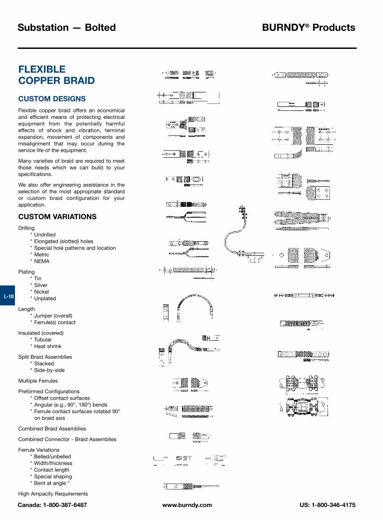
CUSTOM DESIGNS
Flexible copper braid offers an economicaland efficient means of protecting electricalequipment from the potentially harmfuleffects of shock and vibration, terminalexpansion, movement of components andmisalignment that may occur during the service life of the equipment.
Many varieties of braid are required to meetthose needs which we can build to your specifications.
We also offer engineering assistance in theselection of the most appropriate standard or custom braid configuration for your application.
CUSTOM VARIATIONSDrilling
* Undrilled* Elongated (slotted) holes* Special hole patterns and location* Metric* NEMA
Plating* Tin* Silver* Nickel* Unplated
Length* Jumper (overall)* Ferrule(s) contact
Insulated (covered)* Tubular* Heat shrink
Split Braid Assemblies* Stacked* Side-by-side
Multiple Ferrules
Preformed Configurations* Offset contact surfaces* Angular (e.g., 90°, 180°) bends* Ferrule contact surfaces rotated 90°
on braid axis
Combined Braid Assemblies
Combined Connector - Braid Assemblies
Ferrule Variations* Belled/unbelled* Width/thickness* Contact length* Special shaping* Bent at angle °
High Ampacity Requirements

BURNDY® Products Substation — Bolted
US: 1-800-346-4175 www.burndy.com Canada: 1-800-387-6487
Throughout the catalog you will notice blue highlighted items. These are the most frequently ordered BURNDY® Products.
L-11
TYPE B
FLEXIBLE COPPER BRAID JUMPER
* This rating may vary with ambient conditions, orientationof the braid and other service conditions.
** Tongue drilled per NEMA Standard - 9/16� diameter for1/2� diameter bolts on 13/4 C to C.
Number of ApproximateCatalog Braids in Ampere Rating*Number Ferrules C D E K L N T Indoor OutdoorBD12 † 2.50 1.25 .44 12BD12N** † 3.00 1.75 .56 12BD18 † 2.50 1.25 .44 18BD18N** †
1 .943.00 1.75 .56 18
.62 .13 190 225
BD24 † 2.50 1.25 .44 24BD24N** † 3.00 1.75 .56 24BE12 † 1.50 .44 12 .75BE12N** † 1.75 .56 12 .62BE18 † 1.50 .44 18 .75BE18N** †
1 1.50 3.001.75 .56 18 .62
.17 340 405
BE24 † 1.50 .44 24 .75BE24N** † 1.75 .56 24 .62BF12 † 1.50 .44 12 .75BF12N** † 1.75 .56 12 .62BF18 † 1.50 .44 18 .75BF18N** †
1 1.19 3.001.75 .56 18 .62
.25 360 430
BF24 † 1.50 .44 24 .75BF24N** † 1.75 .56 24 .62BG12 1.50 .44 12 .75BG12N** 1.75 .56 12 .62BG18 1.50 .44 18 .75BG18N**
1 1.50 3.001.75 .56 18 .62
.25 415 495
BG24 1.50 .44 24 .75BG24N** 1.75 .56 24 .62B2D12 † 2.50 1.25 .44 12 .62B2D12N** †
.943.00 1.75 .56 12 .62
.25 380 455
B2E12 3.00 1.50 .44 12 .75B2E12N** 2
1.623.00 1.75 .56 12 .62
.25 530 635
B2F12 3.00 1.50 .44 12 .75B2F12N**
1.383.00 1.75 .56 12 .62
.38 600 720
B2G12N** 1.50 3.00 1.75 .56 12 .62 .50 700 840B3D12 † 2.50 1.25 .44 12 .62B3D12N** †
1.193.00 1.75 .56 12 .62
.25 470 560
B3E12 3.00 1.50 .44 12 .75B3E12N**
1.643.00 1.75 .56 12 .62
.31 700 840
B3F123
3.00 1.50 .44 12 .75B3F12N**
1.443.00 1.75 .56 12 .62
.56 820 980
B3G12 3.00 1.50 .44 12 .75B3G12N**
1.693.00 1.75 .56 12 .62
.69 960 1150
B4D12 2.50 1.25 .44 12 .62B4D12N**
1.193.00 1.75 .56 12 .62
.32 600 720
B4E12 3.00 1.50 .44 12 .75B4E12N** 4
1.643.00 1.75 .56 12 .62
.38 850 1020
B4F12 3.00 1.50 .44 12 .75B4F12N**
1.503.00 1.75 .56 12 .62
.78 1000 1200
B4G12N** 1.69 3.00 1.75 .56 12 .62 .94 1200 1440
Note: All sizes are listed to UL467 and specific sizes (†) arecertified to CSA C22.2, No. 41 Grounding and BondingEquipment Standards. Equivalent sizes may be designatedby suffix letters representing variations in length, mount-ing configurations, pad size and finish. Contact factory fordetails.

Substation — Bolted BURNDY® Products
Canada: 1-800-387-6487 www.burndy.com US: 1-800-346-4175
Throughout the catalog you will notice blue highlighted items. These are the most frequently ordered BURNDY® Products.
L-12
TYPE B
EXPANSION COUPLERASSEMBLY COMPONENTS
FOR COPPER BAR
To build your own expansion coupler assem-bly for single or multiple flat bar(s), usingextra flexible tinned copper braid (shown onpage 9) and clamping hardware, the follow-ing table has been provided. The assemblytakes up longitudinal and lateral motion.
Fig. 1
Fig. 2Fig. 3
① Components ordered separately from BURNDY®.② See page 11 for flexible copper braid jumper dimensions
and drilling.③ Bars listed are 1/4� thick. Multiple bars are spaced1/4�.④ For two hole NEMA drilling in each ferrule add suffix letter “N”
to catalog number of braid jumper as shown on page 11.EXAMPLE: B2E12 drilling is .44 dia. holes on 1.50�
centers.B2E12N drilling is .56 dia. holes on 1.75�centers.When specifying NEMA drilling bolt diameterin table must be changed from 38 to 50(length is not changed).
NOTE: Minimum length of each ferrule with NEMA drillingis 3.00�.
⑤ Braid jumper ferrule (pad) thickness is larger than 1/4�requiring assembly to outer contact surface(s) of multiple(1/4� spaced ) bars.
➅ These ratings may vary with ambient conditions, orienta-tion of the braid and other service conditions.
⑦ For other combinations and configurations of flat barcontact BURNDY®.
8. For UL/CSA listing see page 11.
Expansion Coupler Assembly Components ➀Conductor ⑥ Flexible Silicon Bronze Clamping HardwareCopper Bar Approximate ➃ Copper ➁ Split
Width ➁ Ampere Rating Braid Jumper Bolts Nuts Lockwasher Flat Washer Fig.Number ➂ Indoor Outdoor Qty. Cat. No. Qty. Cat. No. Qty. Cat. No. Qty. Cat. No. Qty. Cat. No. No.
1 700 840 2 38X125HEB2 1100 1320 3
B2E1238X175HEB
2 3 1600 1920 4 BG12 4 38X225HEB 4 4 8 13 B2E12
4 1800 21601 B3E12 ➄
38X250HEB
1 1000 1200 4 BG12 38X125HEB2 1650 1980 6 B2E12 38X175HEB
33 2000 2400 8 BG12
838X225HEB
8 8 16
4 2200 2640 8 BG12 38X250HEB1 1350 1620 4 B2E12 38X125HEB 22 2250 2700 2 B2E12 38X225HEB 38CHEN 38SW 38FW
43 2700 3240 6 BG12
838X250HEB
8 8 16
4 3000 3600 6 BG12 38X325HEB1 1600 1920 4 B3E12 8 38X125HEB 8 8 162 2650 3180 9 B2E12 38X175HEB
53 3200 3840 12 BG12 12 38X225HEB 12 12 244 3500 4200 15 BG12 38X275HEB1 1900 2280 6 B2E12 38X125HEB
3 B2E123
62 3150 3780
6 B3E12 1238X175HEB
12 12 243 3800 4560 9 BG12 38X250HEB4 4200 5040 9 BG12 38X325HEB

BURNDY® Products Substation — Bolted
US: 1-800-346-4175 www.burndy.com Canada: 1-800-387-6487
Throughout the catalog you will notice blue highlighted items. These are the most frequently ordered BURNDY® Products.
L-13
TYPE HFBW
BAR CLAMP
FOR COPPER BAR
The clamp assembly eliminates the need fordrilling the flat bar and is used in indoor andoutdoor applications.
The open web design provides a uniformclamping pressure while minimizing theweight of the connector.
FEATURES
• Web design cast copper body.• Fully threaded yellow galvanized bolts with
split-lockwashers and nuts included.• Flat bar accommodation molded into
body.
BENEFITS
• Increased tortional resistance.• Reduced weight.• Simple installation.• Easy identification.
Total NumberStandard of Flat
Catalog Conductor Figure Maximum ‘Z’ Bars (Standard DimensionsNumber * Run Tap Number Dimension 1/4� Thick) Bolt Size W LHFBW86T20CG1 8.0 6.0 2 5.00 20 5/8”-11 8.13 10.13HFBW66T16CG1 6.0 6.0 2 4.00 16 1/2”-13 7.75 7.75HFBW64T17CG1 6.0 4.0 2 4.25 17 1/2”-13 5.75 7.75HFBW44T17CG1 4.0 4.0 2 4.25 17 1/2”-13 5.68 5.68HFBW43T10CG1 4.0 3.0 2 2.50 10 3/8”-16 4.42 5.42HFBW42T10CG1 4.0 2.0 1 2.50 10 3/8”-16 3.54 5.55
* Catalog number based on standard maximum “Z”dimension. Refer to your FCI representative for non-standard “Z” dimensions.
Add TN suffix for tin plating (example: HFBW86T20CG1TN).All dimensions in inches.
Fig. 1 Fig. 2

Substation — Bolted BURNDY® Products
Canada: 1-800-387-6487 www.burndy.com US: 1-800-346-4175
Throughout the catalog you will notice blue highlighted items. These are the most frequently ordered BURNDY® Products.
L-14
TYPE HFB-P1
BAR CLAMP ASSEMBLYCOMPONENTS
FOR COPPER BAR
To build your own high strength clampassembly for multiple flat bar using typeHFB-P1 bar clamps & clamping hardware,the following tables have been provided. Theclamp assembly eliminates the need fordrilling the flat bar and is used in indoor andoutdoor applications.
† Ordered separately from BURNDY®.* Z = Space between the bar clamp contact surfaces.
* *See table below when ordering assembly clamping boltsto specify correct bolt length in Cat. #.
Position for assembly
Bar ClampAssembly
(2) Req’d for assembly
One Clamp HalfBar Clamp Bus Bar “J”
Catalog Run Tap BoltNumber ‘A’ ‘AA’ Dia. L WHFB33P1 3.00 3.00 3/8 4.38 4.38HFB44P1 4.00 4.00 1/2 5.75 5.75HFB63P1 6.00 3.00 1/2 7.75 4.75HFB66P1 6.00 6.00 5/8 8.12 8.12HFB88P1 8.00 8.00 3/4 10.50 10.50
Copper Bar Clamp Assembly Components †Bus Bar Silicon Bronze Clamping Hardware
Width (Inches) Bar Clamp Bolts** Nuts Split LockwashersRun-A Tap-AA Qty. Cat. No. Qty. Cat. No. Qty. Cat. No. Qty. Cat. No.
3 3 2 HFB33P1 4 38 X (*) HEB 4 38CHEN 4 38SW4 4 2 HFB44P1 4 50 X (*) HEB 4 50CHEN 4 50SW6 3 2 HFB63P1 4 50 X (*) HEB 4 50CHEN 4 50SW6 6 2 HFB66P1 4 62 X (*) HEB 4 62CHEN 4 62SW8 8 2 HFB88P1 4 75 X (*) HEB 4 75CHEN 4 75SW
Bolt Length**Clamp ‘J’ When When When When When When When WhenNumber Bolt Dia. Z=1.25* Z=1.50* Z=1.75* Z=2.00* Z=2.25* Z=2.50* Z=2.75* Z=3.00*HFB33P1 3/8�(-16) 3.00 3.25 3.50 4.00 4.00 4.50 4.50 5.00HFB44P1 1/2�(-13) 3.25 3.50 3.75 4.00 4.50 4.50 5.00 5.00HFB63P1 1/2�(-13) 3.25 3.50 3.75 4.00 4.50 4.50 5.00 5.00HFB66P1 5/8�(-11) 3.50 4.00 4.00 4.50 4.50 5.00 5.00 6.00HFB88P1 3/4�(-10) 3.75 4.00 4.50 4.50 5.00 5.00 5.50 5.50

BURNDY® Products Substation — Bolted
US: 1-800-346-4175 www.burndy.com Canada: 1-800-387-6487
Throughout the catalog you will notice blue highlighted items. These are the most frequently ordered BURNDY® Products.
L-15
TYPE HFB-N
BAR CLAMP TAP PADADAPTER
FOR COPPER BAR
High conductivity copper, tap pad adapterprovides a NEMA drilled contact pad whenassembled to the HFB-P1 clamps. Tap con-nections can be made from copper busbar(s) without drilling by bolting standardmechanical or compression terminal padsdirectly to the pre-drilled tap pad adapter.
❶ ‘H’ Clamp (two required per assembly) and hardware (as shown) not included with bar clamp tap pad, orderseparately.
Fig. 1
Fig. 2
Catalog Fig. ❶ Use With ‘H’Number No. A-C E & F L N Clamp Cat. No.HFB33-4N 1 3.00 1.75 7.00 .62 HFB33P1HFB44-4N 1 4.00 1.75 9.12 1.12 HFB44P1HFB66-6N 2 6.00 1.75 11.31 1.12 HFB66P1

Substation — Bolted BURNDY® Products
Canada: 1-800-387-6487 www.burndy.com US: 1-800-346-4175
Throughout the catalog you will notice blue highlighted items. These are the most frequently ordered BURNDY® Products.
L-16
TYPE NA
TERMINAL
FOR COPPER TUBE TO FLAT
High copper alloy terminal for joining coppertube to a flat pad. Letter “N” on end of cata-log number indicates pad drilled to NEMAstandards. One-wrench installation.
TYPE XA
EXPANSION TERMINAL
FOR COPPER TUBE TO FLAT
High copper alloy expansion terminal fortube to flat. Provides for longitudinal move-ment of tubing. Extra flexible braid carries fullload of joint. One-wrench installation.
* Conforms to NEMA Standards
No. ofCatalog HolesNumber Conductor in Pad C D E & F H J K L N TNA13-2N 1/2 2 1-1/2 1-3/4 3/8 3/8NA14-2N 3/4 2 1-5/8 2 3/8 3/8NA15-2N 1 2 1-7/8 2-1/8 3/8
5-1/43/8
NA15-4N 1 4 3 2-1/8 3/8 3/8NA16-2N 1-1/4 2 2-1/4 2-5/8 1/2 1/2NA16-4N 1-1/4 4 3 3 1-3/4 2-5/8 1/2 9/16 5/8 1/2NA17-2N 1-1/2 2 2-1/2 2-3/4 1/2 1/2NA17-4N 1-1/2 4 3 2-3/4 1/2
61/2
NA18-4N 2 4 3-1/8 3-1/ 1/2 1/2NA19-4N 2-1/2 4 3-1/4 3-3/4 1/2 3/4NA21-4N 3-1/2 4 4-3/8 5 5/8 6-5/8 7/8
Catalog Number NumberStandard I.P.S. of Holes
With Guide Conductor in Pad* C H J L TXA18-4N 2 4 3 7 1/2 15-1/4 1/2

BURNDY® Products Substation — Bolted
US: 1-800-346-4175 www.burndy.com Canada: 1-800-387-6487
Throughout the catalog you will notice blue highlighted items. These are the most frequently ordered BURNDY® Products.
L-17
Copper Cable RangeCatalog Fig. Complete Small LargeNumber No. Cable Range Groove Groove B H J Dia. L T WNAS29-N 1B 3.58NAS29-2N 1D 6 Sol. (.162 Dia.) to 6 Sol. (.162 Dia.) to 2/0 Str. (.419 Dia.) to
2.38 1.80 3/8�-165.62
2.00
NAH29-2N 1D 250 kcmil (.575 Dia.) 1/0 Str. (.373 Dia.) 250 kcmil (.575 Dia.) 2.62 2.12 1/2�-13 5.88 .25 2.44NAS29-34N 1E 1.80 5.62 2.00NAS34-N 1C 2.38 3/8�-16 4.12NAS34-2N 1A
2.055.62
2.20
NAH34-2N 1A1/0 Sol. (.325 Dia.) to 1/0 Sol. (.325 Dia.) to 250 kcmil (.575 Dia.) to
2.62 2.38 1/2�-13 5.88.31
2.56NAS34-34N 1E
500 kcmil (.813 Dia.) 4/0 Str. (.529 Dia.) 500 kcmil (.813 Dia.)2.38 2.05 3/8�-16 5.62 2.20
NAH34-34N 1E 2.30 1/2�-13 .25NAS40-2N 1A 2.30 3/8�-16
2.56
2.44NAH40-2N 1A
2/0 Sol. (.365 Dia.) to 2/0 Sol. (.365 Dia.) to 500 kcmil (.813 Dia.) to 2.622.62 1/2�-13 5.88 .38
2.81NAS40-34N 1E 800 kcmil (1.031 Dia.) 500 kcmil (.813 Dia.) 800 kcmil (1.031 Dia.) 2.30 3/8�-16NAH40-34N 1E 2.62 1/2�-13
2.44
NAH40-44N 1 .31 2.44NAH44-2N 1A 6.88NAH44-34N 1E
4/0 Str. (.528 Dia.) to 4/0 Str. (.528 Dia.) to 750 kcmil (.998 Dia.) to2.88
2.62 2.81
NAH44-44N 11000 kcmil (1.152 Dia.) 750 kcmil (.998 Dia.) 1000 kcmil (1.152 Dia.)
.44NAH46-2N 1A
6.12.38 2.88
1000 kcmil (1.152 Dia.) 1000 kcmil (1.152 Dia.)7.12 .31
NAH46-34N 1E to 1500 kcmil — to 1500 kcmil 3.06 2.88 1/2�-13.50
NAH46-44N 1(1.412 Dia.) (1.412 Dia.) 6.31
.413.19
NAH48-2N 1A 7.31 .38500 kcmil (.813 Dia.) to 500 kcmil (.813 Dia.) to 1500 kcmil (1.412 Dia.) to .69
NAH48-34N 1E2000 kcmil (1.632 Dia.) 1500 kcmil (1.412 Dia.) 2000 kcmil (1.632 Dia.)
3.25 3.12 6.50.50
3.38
NAH48-44N 1 7.50 .44
TYPE NAS/NAH
TERMINAL
FOR COPPER CABLE
High copper alloy reversible cap terminal forjoining a wide range of cable to equipmentpads. Tongue is side formed to provideadequate clearance and terminal is designedfor one-wrench installation.
Fig. 1
Fig. “A” Fig. “B” Fig. “C”
Fig. “D” Fig. “E”

Substation — Bolted BURNDY® Products
Canada: 1-800-387-6487 www.burndy.com US: 1-800-346-4175
Throughout the catalog you will notice blue highlighted items. These are the most frequently ordered BURNDY® Products.
L-18
TYPE N2AH
TERMINAL
FOR TWO COPPER CABLES TO FLAT
High copper alloy, reversible cap terminal forjoining a wide range of two copper cables toequipment pads. Tongue is side formed toprovide adequate clearance and terminal isdesigned for one-wrench installation.
W
H
J L
T
B
U
Fig. 1 Fig. 2
Copper Cable RangeCatalog Fig. Complete Small Large Dimensions Inches/[mm]Number No. Cable Range Groove Groove B H U J Dia. L T W
1/0 Str. (.325) to 1/0 Sol. (.325) to 250 kcmil (.575) to 2.63 2.30 2.88 6.13 .31 3.88N2AH34-34N 1
500 kcmil (.813) 4/0 Str. (.529) 500 kcmil (.813) [67] [58] [156] [8] [99]2/0 Str. (.420) to 2/0 Str. (.420) to 500 kcmil (.813) to 2.63 2.62 2.92 5.88 .31 5.70
N2AH40-34N 1800 kcmil (1.031) 500 kcmil (.813) 800 kcmil (1.031) [67] [67] [149] [8] [145]4/0 Str. (.529) to 4/0 Str. (.529) to 750 kcmil (.998) to 2.88 2.62 3.12 6.38 .50 4.69
N2AH44-34N 11000 kcmil (1.152) 750 kcmil (.998) 1000 kcmil (1.152) [73] [67]
1/2 - 13[175] [13] [119]
4/0 Str. (.529) to 4/0 Sol. (.529) to 750 kcmil (.998) to 2.88 2.25 3.12 7.32 .50 6.12N2AH44-44N 2
1000 kcmil (1.152) 750 kcmil (.998) 1000 kcmil (1.152) [73] [57] [186] [13] [155]1000 kcmil (1.152) to 3.07 2.50 3.36 7.46 .75 6.50
N2AH46-44N 21500 kcmil (1.411)
— —[78] [64] [189] [19] [165]

BURNDY® Products Substation — Bolted
US: 1-800-346-4175 www.burndy.com Canada: 1-800-387-6487
Throughout the catalog you will notice blue highlighted items. These are the most frequently ordered BURNDY® Products.
L-19
TYPE VA, VVA
VARILUG
FOR COPPER CABLE
High copper alloy terminal for joining a widerange of cable to equipment pads or bar.Particularly suitable for use on extra flexiblecable. One-wrench installation. Type VVA,twin elements secure joint against vibrationand flexing. Particularly recommended foruse on extra flexible cables. One-wrenchinstallation.
* “N” indicates NEMA standard stud holes.
Type VA
Type VVA
No. ofCatalog Number* Holes
Type VA Type VVA Conductor in Pad C D E & F H K L LL N TVA2C — 8 Sol. - 2 Str. 13/16 1-1/4 — 1-1/2 2-3/4 4-1/8 3/8VA25 — 6 Sol. - 1/0 Str.
17/8 1-3/8 — 1-7/8
7/162-1/8 4-3/8 1/2
1/4
VA28 VVA28 1 1-1/2 — 7/16 2-5/8 4-1/8 1/2VA28-2N VVA28-2N
1/0 Str. - 4/0 Str.2 NEMA
1-1/163-1/2 1-3/4
1-7/89/16 5 6-1/4 5/8
VA30 VVA30 1 1-5/8 — 7/16 3-1/4 4-5/8 5/85/16
VA30-2N VVA30-2N1/0 Str. - 300
2 NEMA1-1/8
3-5/8 1-3/42-1/4
9/16 5-1/4 6-5/8 5/8VA34 VVA34 1 2 — 9/16 3-7/8 5-3/8 7/8VA34-2N VVA34-2N 300 - 500 2 NEMA
1-3/83-5/8 1-3/4
2-5/89/16 5-3/8 6-1/8 5/8
— VVA34-4N 4 NEMA 3 3-1/16 1-3/4 2-9/16 9/16 5-3/8 6-7/8 5/8VA40 VVA40 1 2-3/8 — 11/16 4-1/2 6-3/8 1
3/8
VA40-2N VVA40-2N 500 - 800 2 NEMA1-5/8
3-5/8 1-3/4 2-1/8 9/16 5-7/8 7-3/4 5/8VA40-4N VVA40-4N 4 NEMA 3 2-5/8 1-3/4 9/16 5-7/8 7-3/4 5/8

Substation — Bolted BURNDY® Products
Canada: 1-800-387-6487 www.burndy.com US: 1-800-346-4175
Throughout the catalog you will notice blue highlighted items. These are the most frequently ordered BURNDY® Products.
L-20
TYPE UH
BUS SUPPORT
FOR COPPER TUBE
High copper alloy bus support for mountingtube on a post or pedestal type insulator.Single bolt allows rotation to any angle.Rotate cap 180° for slip or rigid fit. One-wrench installation. Supplied with hardwarefor mounting to cap of insulator. Specify basemounting hardware, if required, by addingsuffix “B” to Catalog No.
TYPE UHR
BUS SUPPORT
FOR COPPER CABLE OR TUBE
High copper alloy bus support clamp formounting a wide range of cable or tube onpost or pedestal type insulators. Single boltallows rotation to any angle. Supplied withhardware for mounting to cap of insulator.Specify base mounting hardware, if required,by adding suffix “-B” to Catalog No.
* With maximum conductor in place.
CopperCatalog Conductor BoltNumber IPS “A” Circle B G H J K WUH14-3 3/4 3 2 2-7/8 9/16 2-5/8UH15-3 3 2-1/2 2 3 3/8 9/16UH15-5
15 3-1/4 11/16
2-7/8
UH16-3 32-1/4
3-1/2 9/16UH16-5
1-1/45
2-11/162-3/8 3-5/8 11/16
3-1/2
UH17-3 3 9/16UH17-5
1-1/25
2-1/2 3-7/811/16
4
UH18-3 31/2
9/16UH18-5
25
3 2-3/4 4-3/811/16
4-5/8
UH19-3 3 9/16UH19-5
2-1/25
3-1/8 511/16
5-1/4
UH20-3 3 9/16UH20-5
35 3-1/4
3-5/8 5-7/85/8 11/16
6-1/4
UH22-5 4 5 4-1/2 7-1/4 11/16 7-1/2
Catalog Copper Conductor “A” BoltNumber Cable Tube Circle B G* H J K WUHR13-3 3 1-3/4 3 9/16UHR13-5
6 Str. - 500 1/8 - 1/25
3-5/82-1/8 3-3/8 11/16
2-1/4
UHR15-3 3 2 3-1/23/8
9/16UHR15-5
4/0 Str. - 1250 1/4 - 15
3-3/42-1/4 3-3/4 11/16
2-3/4
UHR17-3 3 9/16UHR17-5
750 - 2500 3/4 - 1-1/25
2-7/8 2-1/2 4-1/4 1/211/16
4

BURNDY® Products Substation — Bolted
US: 1-800-346-4175 www.burndy.com Canada: 1-800-387-6487
Throughout the catalog you will notice blue highlighted items. These are the most frequently ordered BURNDY® Products.
L-21NOTES:1 Material:
Connector: Cast copper alloyClamping Hardware: Silicon bronzeMounting Hardware: Galvanized steel
2 Dimensions in brackets [ ] are in millimeters.
➂ Complete range may be accommodated by reversingthe cap.
➃ Dimension with maximum conductor in place.
TYPES LH, LHR
BUS SUPPORT
FOR COPPER CABLE OR TUBE
High copper alloy, light duty bus support formounting a wide range of cable or tube onpost or pedestal type insulators. One-wrenchinstallation. Supplied with hardware formounting to cap of insulator. Specify basemounting hardware, if required, by addingsuffix “-B” to Catalog No.
➄ Cap mounting hardware is supplied as standard. 3.00Dia. bolt circle furnished with four 1/2 -13 � 1.00 longgalvanized steel hex head bolts and split lockwashers.5.00 Dia. bolt circle furnished as above except bolts are.625 � 1.75.
➅ If base mounting is desired, add “-B” to the CatalogNumber and the following hardware will be supplied:3.00 Dia. bolt circle furnished 1/2 -13 � 1-1/2 long gal-vanized steel hex head bolt, hex nuts, and 5.00 Dia. boltcircle furnished as above except bolts are .625 � 1.75.
Copper Cable Range Tubing ➄ Bolt ➅ Catalog Dimensions Inches/[mm]Complete Range Schedule 40/80 Circle Number B G ➃ H ➃ J K W
1.69 1.25 2.62 .56 4.256 Sol. - 4/0 Str. — 3� LH28-3
[43] [32] [66.5] [14] [108]1.00 1.23 2.03 .56 4.25
➂ #8 - 250 kcmil 1/8 - 1/4 3� LHR29-3[25] [31] [52]
3/8 - 16[14] [108]
1.38 1.38 2.50 .56 4.252/0 Str. - 500 kcmil 1/4 - 1/2 3� LH34-3
[35] [35] [63.5] [14] [108]

Substation — Bolted BURNDY® Products
Canada: 1-800-387-6487 www.burndy.com US: 1-800-346-4175
Throughout the catalog you will notice blue highlighted items. These are the most frequently ordered BURNDY® Products.
L-22
TYPE NDR
STUD CONNECTOR
FOR COPPER CABLE, TUBE, FLAT BAR
High copper alloy reversible and rotatablecap stud connector joins cable, tube and flatbar in-line or at right angles to equipmentstuds. Accommodates a wide range ofcables or tubes. One-wrench installation.
Fig. 1
Fig. 2
Catalog Stud Complete Range AA Fig. X XX Z ZZNumber A Cable Tube I.P.S. No. Groove Groove Groove Groove E H J JJ LNDR6328T13 1/2-13 6 Sol. - 4/0 Str. — 6 Sol. - 1 Str. 2/0 Sol. - 4/0 Str.NDR6428T16 6 Sol. - 4/0 Str. —
16 Sol. - 1 Str. 2/0 Sol. - 4/0 Str.
1-1/16 1-3/43/8
3-5/8
NDR6434T16 3/4-16 6 Sol. - 500 3/8 - 1/2 250 - 350 400 - 500 6 Sol. - 2 Str. 1/0 Sol. - 4/0 Str. 1-7/16 2-1/4 4-1/8NDR6444T16 2 Sol. - 1000 3/8 - 3/4
2550 - 700 750 - 1000 2 Sol. - 250 300 - 500 1-7/8 2-7/8 1/2 4-5/8
NDR6528T14 6 Sol. - 4/0 Str. — 1 6 Sol. - 1 Str. 2/0 Sol. - 4/0 Str. 1-1/16 1-3/4 4-1/8NDR6534T14 1-14 6 Sol. - 500 3/8 - 1/2 250 - 350 400 - 500 6 Sol. - 2 Str. 1/0 Sol. - 4/0 Str. 1-7/16 2-1/4 3/8
3/84
NDR6544T14 2 Sol. - 1000 3/8 - 3/42
550 - 700 750 - 1000 2 Sol. - 250 300 - 500 1-7/8 2-7/8 1/2 4-3/4NDR65528T12 6 Sol. - 4/0 Str. — 1 6 Sol. - 1 Str. 2/0 Sol. - 4/0 Str. 1-1/16 1-3/4 4-1/8NDR65534T12 1-1/8-12 6 Sol. - 500 3/8 - 1/2 250 - 350 400 - 500 6 Sol. - 2 Str. 1/0 Sol. - 4/0 Str. 1-7/16 2-1/4
3/84
NDR65544T12 2 Sol. - 1000 3/8 - 3/4 2 550 - 700 750 - 1000 2 Sol. - 250 300 - 500 1-7/8 2-7/8 4-5/8NDR6644T12 1-1/4-12 2 Sol. - 1000 3/8 - 3/4 550 - 700 750 - 1000 2 Sol. - 250 300 - 500 1-7/8 2-7/8
1/24-5/8
NDR6728T12 6 Sol. - 4/0 Str. — 1 6 Sol. - 1 Str. 2/0 Sol. - 4/0 Str. 1-1/16 2-1/4 4-3/4NDR6734T12 6 Sol. - 500 3/8 - 1/2 250 - 350 400 - 500 6 Sol. - 2 Str. 1/0 Sol. - 4/0 Str. 1-7/16 2-3/8
3/85
NDR6744T121-1/2-12
2 Sol. - 1000 3/8 - 3/4 550 - 700 750 - 1000 2 Sol. - 250 300 - 500 1-7/8 2-7/8 5-1/8NDR6748T12 4/0 Str. - 2000 3/8-1-1/4 2 1250 - 1600 1700 - 2000 4/0 Str. - 600 650 - 1200 2-3/8 3-1/4
1/25-3/4
NDR6844T12 2 Sol. - 1000 3/8 - 3/4 550 - 700 750 - 1000 2 Sol. - 250 300 - 500 1-7/81/2
6-1/8NDR6848T12
2-124/0 Str. - 2000 3/8-1-1/4 1250 - 1600 1700 - 2000 4/0 Str. - 600 650 - 1200 2-3/8
2-7/86-5/8

BURNDY® Products Substation — Bolted
US: 1-800-346-4175 www.burndy.com Canada: 1-800-387-6487
Throughout the catalog you will notice blue highlighted items. These are the most frequently ordered BURNDY® Products.
L-23
TYPE FD
STUD CONNECTOR
FOR STUD TO FLAT BAR
High copper alloy stud connector allowsbolting cable and tubing terminals to equip-ment studs. Hex head captured bolts provideone-wrench installation. One pad contactsurface is on centerline of stud. Pad is fin-ished on both sides. All pads are four hole NEMA drilled.
NOTES:➀ Indoor Rating2. Contact factory for other variations in drilling, plating, etc.
NominalCatalog Stud AmpereNumber A Rating ➀ B C D J L N TFD64C5T16 3/4� -16 1000 3.00 3.00 5.72 .62 .31FD65C6T14 1�-14 1075 3.00 3.00 5.72 .62 .38FD655C6 1075 3.00 3.00 5.80 .62 .38FD655D6
1-1/8�-121300
1.754.00 4.00
3/8�-166.86 1.12 .38
FD66C6 1075 3.00 3.00 5.78 .62 .38FD66D6
1-1/4�-121300 4.00 4.00 6.84 1.12 .38
FD67C6 1075 3.00 3.00 6.23 .62 .38FD67D8
1-1/2�-121450 4.00 4.00 7.30 1.12 .50
FD675C8 1220 3.00 3.00 6.32 .62 .50FD675D8
1-3/4�-121450 2.18 4.00 4.00 7.39 1.12 .50
FD68C8 1220 3.00 3.00 6.35 .62 .50FD68D8 2�-12 1450 4.00 4.00 7.42 1.12 .50FD68D12 2100 4.00 4.00 1/2�-13 7.42 1.12 .75FD685C8 1220 3.00 3.00 6.71 .62 .50FD685D8 2-1/4�-12 1450 4.00 4.00 7.77 1.12 .50FD685D12 2100 4.00 4.00 7.77 1.12 .75FD69C8 1220
2.503.00 3.00 6.77 .62 .50
FD69D8 2-1/2�-12 1450 4.00 4.00 8.03 1.12 .50FD69D12 2100 4.00 4.00 8.03 1.12 .75FD70D12 2100 4.00 4.00 8.26 1.12 .75FD70D16
3�-123000
2.884.00 4.00
5/8�-118.24 1.12 1.00
Substation — Bolted BURNDY® Products
Canada: 1-800-387-6487 www.burndy.com US: 1-800-346-4175
Throughout the catalog you will notice blue highlighted items. These are the most frequently ordered BURNDY® Products.
L-24
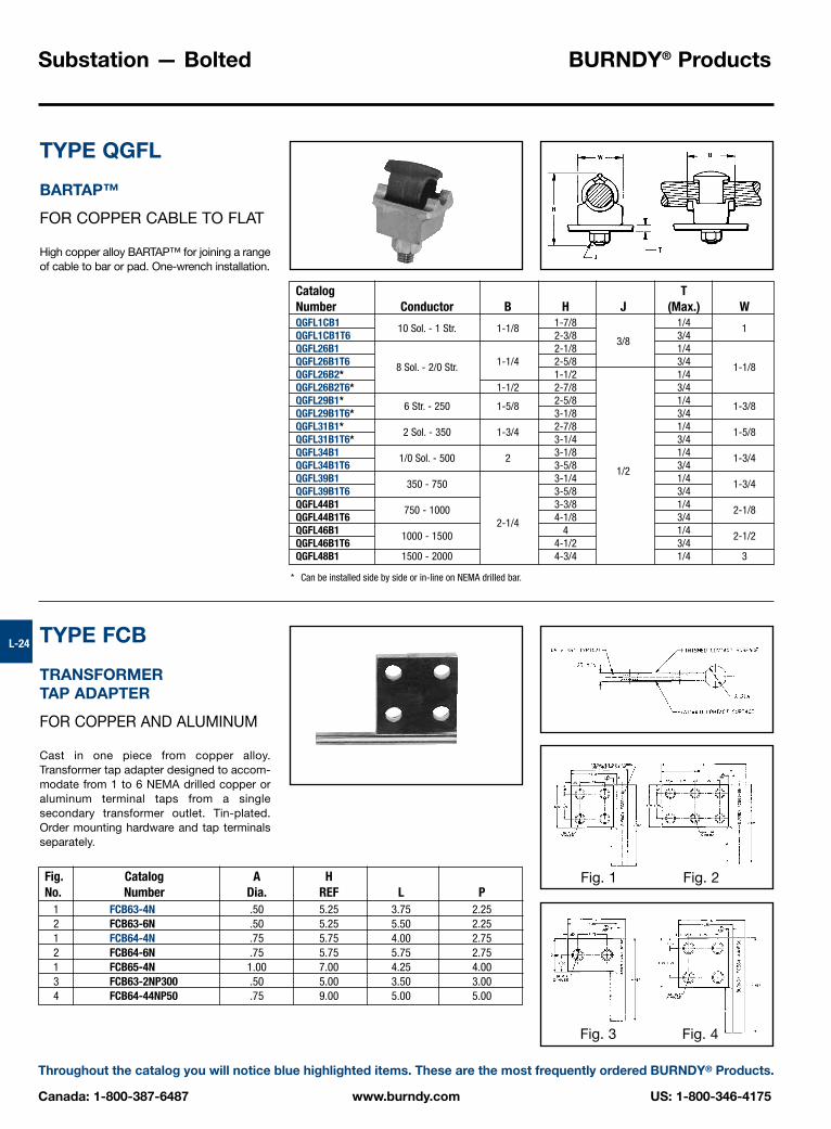
TYPE QGFL
BARTAP™
FOR COPPER CABLE TO FLAT
High copper alloy BARTAP™ for joining a rangeof cable to bar or pad. One-wrench installation.
TYPE FCB
TRANSFORMER TAP ADAPTER
FOR COPPER AND ALUMINUM
Cast in one piece from copper alloy.Transformer tap adapter designed to accom-modate from 1 to 6 NEMA drilled copper oraluminum terminal taps from a single secondary transformer outlet. Tin-plated. Order mounting hardware and tap terminalsseparately.
* Can be installed side by side or in-line on NEMA drilled bar.
Fig. 1 Fig. 2
Fig. 3 Fig. 4
Catalog TNumber Conductor B H J (Max.) WQGFL1CB1 1-7/8 1/4QGFL1CB1T6
10 Sol. - 1 Str. 1-1/82-3/8 3/4
1
QGFL26B1 2-1/83/8
1/4QGFL26B1T6 1-1/4 2-5/8 3/4QGFL26B2*
8 Sol. - 2/0 Str.1-1/2 1/4
1-1/8
QGFL26B2T6* 1-1/2 2-7/8 3/4QGFL29B1* 2-5/8 1/4QGFL29B1T6*
6 Str. - 250 1-5/83-1/8 3/4
1-3/8
QGFL31B1* 2-7/8 1/4QGFL31B1T6*
2 Sol. - 350 1-3/43-1/4 3/4
1-5/8
QGFL34B1 3-1/8 1/4QGFL34B1T6
1/0 Sol. - 500 23-5/8 3/4
1-3/4
QGFL39B1 3-1/41/2
1/4QGFL39B1T6
350 - 7503-5/8 3/4
1-3/4
QGFL44B1 3-3/8 1/4QGFL44B1T6
750 - 10004-1/8 3/4
2-1/8
QGFL46B12-1/4
4 1/4QGFL46B1T6
1000 - 15004-1/2 3/4
2-1/2
QGFL48B1 1500 - 2000 4-3/4 1/4 3
Fig. Catalog A HNo. Number Dia. REF L P
1 FCB63-4N .50 5.25 3.75 2.252 FCB63-6N .50 5.25 5.50 2.251 FCB64-4N .75 5.75 4.00 2.752 FCB64-6N .75 5.75 5.75 2.751 FCB65-4N 1.00 7.00 4.25 4.003 FCB63-2NP300 .50 5.00 3.50 3.004 FCB64-44NP50 .75 9.00 5.00 5.00

BURNDY® Products Substation — Bolted
US: 1-800-346-4175 www.burndy.com Canada: 1-800-387-6487
Throughout the catalog you will notice blue highlighted items. These are the most frequently ordered BURNDY® Products.
L-25
TYPE E-C-G
TRANSFORMER TAP ADAPTER
FOR COPPER CABLE
Multi-tap, range-taking cast copper alloyconnector designed to take 2, 3, or 4 con-ductors from a single secondary transformeroutlet.
TYPE FN
CONTACT NUT
FLAT TO STUD
High copper alloy contact nut for joining baror terminal pads to studs. Designed to carryfull current load from flat to stud.
Catalog Number of ANumber Conductors Conductor Size Dia. D H J L WE2C34G1 2 3-1/2E3C34G1 3 1/0 Sol. to 500 .78 3-3/4 3-7/8 1/2-13 6-1/4 5-1/4E4C34G1 4 6-7/8
Catalog Number Stud Dia. and CFType FN Threads per Inch (Cross Flats) H T WFN62T16 3/8 - 16 3/4 3/8 5/16 7/8FN63T13 1/2 - 13 1 15/32 3/8 1-1/4FN64T16 3/4 - 16 1-1/4 3/4 9/16 1-1/2FN655T12 1-1/8 - 12 1-3/4 1 3/4 2-1/8FN66T14 1-1/4 - 14 2 2-3/8FN67T12 1-1/2 - 12 2-3/8
1-1/8 7/82-3/4

Substation — Bolted BURNDY® Products
Canada: 1-800-387-6487 www.burndy.com US: 1-800-346-4175
Throughout the catalog you will notice blue highlighted items. These are the most frequently ordered BURNDY® Products.
L-26
CONNECTORS FOR ALUMINUM CONDUCTORS
Bolted aluminum connectors are cast of alu-minum alloy and assembled with aluminumalloy bolts, nuts and galvanized steelwashers. The hex head bolts are captured forone-wrench installation. The connectorsaccommodate aluminum or copper conduc-tor. The “mass anode” design pioneered byBURNDY® minimizes the effect of galvaniccorrosion on aluminum (anode+) connectorswhen used with copper (cathode –) conduc-tor (Reference Fig. 1).
Joint deterioration caused by relaxation or“cold flow” of the aluminum is eliminated bythe massive design. Generous contact areasdistribute clamping forces evenly over theconductor, eliminating points of high stressthat cause “cold flow.” These contact areasare factory treated to remove surface oxidesand coated with an oxide inhibitor to preventtheir reformation. Large radiating surfacesallow the connectors to run cooler than thecopper conductor compensating for the factthat aluminum has a higher coefficient ofthermal expansion. Connector and conduc-tor expand and contract together during loadcycles, eliminating stresses on the aluminumbody that can cause relaxation of the joint.
CONNECTOR SELECTION
Generally, copper connectors are recom-mended for copper conductor and aluminumconnectors for aluminum conductor. Wherealuminum connectors are recommended foruse on both aluminum and copper conduc-tors, the copper must be positioned parallelto or below the aluminum to prevent contam-ination of the aluminum by copper saltswashed down by rain.
Except where indicated, all rigid connectorsaccept standard or extra heavy I.P.S. and allflexible connectors standard I.P.S. If extraheavy I.P.S. is to be used with a flexible joint,it must be spelled out at the time of orderingso that the proper cross sectional area of theflexible element may be supplied for theincreased conductor rating.
CONDUCTOR PREPARATION
To obtain optimum performance from anyconnector, the conductor surface must bethoroughly cleaned before installation. Thesurface oxides that form on all conductorsact as insulation. Failure to remove them can result in high resistance joint and, ulti-mately, failure.
Conductor contact surfaces should bescratch brushed until bright and shiny.Aluminum conductor (new or old) should becoated with BURNDY® PENETROX™ afterscratch brushing. PENETROX™ is a jointcompound that aids in the establishment oflow resistance joints and prevents aluminumoxides from reforming.
ALUMINUM INTRODUCTION
Fig. 1
Many aluminum ionsremoved by current flow
Few aluminum ionsremoved by current flow
Copper Cathode
Aluminum Anode
Aluminum Anode
Copper Cathode
BURNDY® Products Substation — Bolted
US: 1-800-346-4175 www.burndy.com Canada: 1-800-387-6487
Throughout the catalog you will notice blue highlighted items. These are the most frequently ordered BURNDY® Products.
L-27
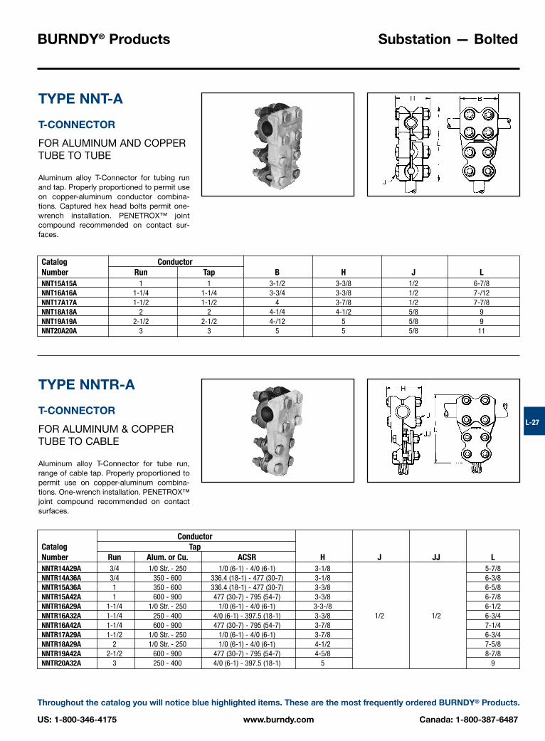
TYPE NNT-A
T-CONNECTOR
FOR ALUMINUM AND COPPERTUBE TO TUBE
Aluminum alloy T-Connector for tubing runand tap. Properly proportioned to permit useon copper-aluminum conductor combina-tions. Captured hex head bolts permit one-wrench installation. PENETROX™ jointcompound recommended on contact sur-faces.
TYPE NNTR-A
T-CONNECTOR
FOR ALUMINUM & COPPERTUBE TO CABLE
Aluminum alloy T-Connector for tube run,range of cable tap. Properly proportioned topermit use on copper-aluminum combina-tions. One-wrench installation. PENETROX™joint compound recommended on contactsurfaces.
Catalog ConductorNumber Run Tap B H J LNNT15A15A 1 1 3-1/2 3-3/8 1/2 6-7/8NNT16A16A 1-1/4 1-1/4 3-3/4 3-3/8 1/2 7-/12NNT17A17A 1-1/2 1-1/2 4 3-7/8 1/2 7-7/8NNT18A18A 2 2 4-1/4 4-1/2 5/8 9NNT19A19A 2-1/2 2-1/2 4-/12 5 5/8 9NNT20A20A 3 3 5 5 5/8 11
ConductorCatalog TapNumber Run Alum. or Cu. ACSR H J JJ LNNTR14A29A 3/4 1/0 Str. - 250 1/0 (6-1) - 4/0 (6-1) 3-1/8 5-7/8NNTR14A36A 3/4 350 - 600 336.4 (18-1) - 477 (30-7) 3-1/8 6-3/8NNTR15A36A 1 350 - 600 336.4 (18-1) - 477 (30-7) 3-3/8 6-5/8NNTR15A42A 1 600 - 900 477 (30-7) - 795 (54-7) 3-3/8 6-7/8NNTR16A29A 1-1/4 1/0 Str. - 250 1/0 (6-1) - 4/0 (6-1) 3-3-/8 6-1/2NNTR16A32A 1-1/4 250 - 400 4/0 (6-1) - 397.5 (18-1) 3-3/8 1/2 1/2 6-3/4NNTR16A42A 1-1/4 600 - 900 477 (30-7) - 795 (54-7) 3-7/8 7-1/4NNTR17A29A 1-1/2 1/0 Str. - 250 1/0 (6-1) - 4/0 (6-1) 3-7/8 6-3/4NNTR18A29A 2 1/0 Str. - 250 1/0 (6-1) - 4/0 (6-1) 4-1/2 7-5/8NNTR19A42A 2-1/2 600 - 900 477 (30-7) - 795 (54-7) 4-5/8 8-7/8NNTR20A32A 3 250 - 400 4/0 (6-1) - 397.5 (18-1) 5 9

Substation — Bolted BURNDY® Products
Canada: 1-800-387-6487 www.burndy.com US: 1-800-346-4175
Throughout the catalog you will notice blue highlighted items. These are the most frequently ordered BURNDY® Products.
L-28
TYPE NNTR-A
T-CONNECTOR
FOR ALUMINUM AND COPPERCABLE TO CABLE
Aluminum alloy T-Connector for a range ofcopper, aluminum and ACSR cable on runand tap. Properly proportioned to permit useon copper-aluminum conductor com-binations. One-wrench installation. PENE-TROX™ joint compound recommended oncontact surfaces.
TYPE NS-A
COUPLER
FOR ALUMINUM AND COPPERTUBE TO TUBE
Aluminum alloy coupler for joining equalsizes of tube end to end. Properly propor-tioned to permit use on aluminum-copperconductor combinations. One-wrench instal-lation. PENETROX™ joint compound recom-mended on contact surfaces.
Fig. 1
Fig. 2
Fig. 1 Fig. 2
ConductorRun Tap
Catalog Alum. or Alum. or Fig.Number Copper ACSR Copper ACSR No. B H J LNNTR29A29A 1/0 Str. - 250 1/0 (6-1) - 4/0 (6-1) 1/0 Str. - 250 1/0 (6-1) - 4/0 (6-1) 2 2-3/4 2-5/8 5-5/8NNTR32A25A 250 - 400 4/0 (6-1) - 397.5 (18.1) 4 Str. - 1/0 Str. 4 (6-1) - 1/0 (6-1) 1 1-7/8 2-5/8 4-7/8NNTR32A32A 250 - 400 4/0 (6-1) - 397.5 (18-1) 250 - 400 4/0 (6-1) - 397.5 (18-1) 2 3 2-5/8 6NNTR36A29A 350 - 600 336.4 (18-1) - 477 (30-7) 1/0 Str. - 250 1/0 (6-1) - 4/0 (6-1) 2 3-1/4 2-5/8 5-7/8NNTR36A36A 350 - 600 336.4 (18-1) - 477 (30-7) 350 - 600 336.4 (18-1) - 477 (30-7) 2 3-1/4 2-5/8 6-3/8NNTR42A32A 600 - 900 477 (30-7) - 795 (54-7) 250 - 400 4/0 (6-1) - 397.5 (18-1) 2 3-1/2 3-1/8
1/26-3/8
NNTR42A36A 600 - 900 477 (30-7) - 795 (54-7) 350 - 600 336.4 (18-1) - 477 (30-7) 2 3-1/2 3-1/8 6-5/8NNTR42A42A 600 - 900 477 (30-7) - 795 (54-7) 600 - 900 477 (30-7) - 795 (54-7) 2 3-1/2 3-1/8 6-7/8NNTR45A45A 900 - 1250 715.5 (30-19) - 1113 (54-19) 900 - 1250 715.5 (30-19) - 1113 (54-19) 2 3-3/4 3-1/4 7-3/8NNTR46A42A 1250 - 1600 1113 (54-19) - 1431 (45-7) 600 - 900 477 (30-7) - 795 (54-7) 2 3-3/4 3-1/2 7-1/4NNTR46A46A 1250 - 1600 1113 (54-19) - 1431 (45-7) 1250 - 1600 1113 (54-19) - 1431 (45-7) 2 4-3/8 3-3/4 5/8 8-3/8NNTR48A48A 1500 - 2000 1272 (54-19) - 1780 (84-19) 1500 - 2000 1272 (54-19) - 1780 (84-19) 2 4-3/8 3-7/8 5/8 8-5/8
Catalog Conductor Fig.Number I.P.S. No. J LNS14A14A 3/4 6-3/4NS15A15A 1 1/2 7-1/4NS17A17A 1-1/2 8-1/4NS18A18A 2 8-3/4NS19A19A 2-1/2
19-1/4
NS20A20A 3 10-1/4NS21A21A 3-1/2
5/811-1/4
NS22A22A 4 12-1/4NS24A24A 5 2 14-1/4

BURNDY® Products Substation — Bolted
US: 1-800-346-4175 www.burndy.com Canada: 1-800-387-6487
Throughout the catalog you will notice blue highlighted items. These are the most frequently ordered BURNDY® Products.
L-29
TYPE NA-A
TERMINAL
FOR ALUMINUM AND COPPERTUBE TO FLAT
Aluminum alloy terminal for joining copper oraluminum tube to copper or aluminum pad.Properly proportioned to minimize conductorcorrosion due to galvanic action. Drilling inpad conforms to NEMA standards. One-wrench installation. PENETROX™ joint com-pound recommended on contact surfaces.
TYPE XA-A
EXPANSION TERMINAL
FOR ALUMINUM AND COPPERTUBE TO FLAT
Aluminum alloy expansion connector for join-ing tube to copper or aluminum bar or equip-ment pads. Flexible aluminum straps allowlongitudinal or lateral movement and carriesfull current load of the joint. PENETROX™joint compound recommended on contactsurfaces. Pad contact surface is on center-line of conductor.
* Conforms to 4-hole NEMA mounting standards.
Fig. 1Fig. 2
Catalog Fig.Number Conductor No. B C G H J L T WNA15A-2N 1 2 3-1/2 1-7/8 1.50 3-3/8 1/2 6-3/4 3/8 3-1/16NA15A-4N 1 1 3-1/2 3 1.50 3-3/8 1/2 6-3/4 3/8 3-1/16NA16A-4N 1-1/4 1 3-3/4 3 1.60 3-3/8 1/2 7 1/2 3-7/16NA17A-2N 1-1/2 2 4 2-1/2 1.76 3-7/8 1/2 7-1/2 1/2 3-11/16NA17A-4N 1-1/2 1 4 3 1.76 3-7/8 1/2 7-1/2 1/2 3-11/16NA18A-2N 2 2 4-1/4 2-3/4 2.05 4-1/2 5/8 7-1/2 1/2 4-1/2NA18A-4N 2 1 4-1/4 3-1/8 2.05 4-1/2 5/8 7-1/2 1/2 4-1/2NA19A-4N 2-1/2 1 4-1/2 3-3/4 2.19 5 5/8 7-3/4 3/4 5NA20A-4N 3 1 5 4-3/8 2.43 5-1/2 5/8 8-3/8 3/4 5-5/8
Catalog Number*Standard I.P.S.
(Schedule 40) With Guide Conductor C J L TXA15A-4N 1 3 12-3/4 3/8XA16A-4N 1-1/4 3
1/213-5/8 1/2
XA18A-4N 2 3 15-1/2 1/2XA19A-4N 2-1/2 3-3/4 17 5/8XA20A-4N 3 4-3/8 18-5/8 5/8XA21A-4N 3-1/2 4-3/4
5/820 7/8
XA22A-4N 4 5-1/4 21 7/8XA24A-4N 5 6-1/2 24-1/8 7/8

Substation — Bolted BURNDY® Products
Canada: 1-800-387-6487 www.burndy.com US: 1-800-346-4175
Throughout the catalog you will notice blue highlighted items. These are the most frequently ordered BURNDY® Products.
L-30
NOTES:1. Materials:
Connector: Cast Aluminum AlloyHardware: Aluminum Alloy
TYPE NBC-A
BARTAP™
Aluminum alloy bolted type terminal for join-ing aluminum tube to copper or aluminumpads. Drilling in pad conforms to NEMAStandards. PENETROX™ joint compound recommended on contact surfaces.
Fig. 1 Fig. 2 Fig. 3
ConductorAluminum Catalog Fig. Dimensions Inches [mm]
IPS/EHPS A Number No. B H J L T Y1.32 NBC15A-2N 1 3.50 3.00 6.81 .38 5.28
1�[33] NBC15A-34N 2 [89] [76]
1/2 - 13[173] [10] [134]
1.66 3.75 3.25 7.15 .38 5.451-1/4�
[42]NBC16A-2N 1
[95] [76]1/2 - 13
[182] [10] [138]4.00 3.50 7.39 .38 5.57
NBC17A-2N 1[102] [89]
1/2 - 13[188] [10] [141]
1.90 4.00 3.50 7.39 .38 5.571-1/2�
[48]NBC17A-34N 2
[102] [89]1/2 - 13
[188] [10] [141]4.00 3.50 8.39 .38 6.57
NBC17A-44N 3[102] [89]
1/2 - 13[213] [10] [167]
4.25 4.00 8.25 .38 6.00NBC18A-2N 1
[108] [76]5/8 - 11
[210] [10] [152]2.38 4.25 4.00 8.25 .38 6.00
2�[42]
NBC18A-34N 2[108] [76]
5/8 - 11[210] [10] [152]
4.25 4.00 9.25 .38 7.00NBC18A-44N 3
[108] [76]5/8 - 11
[135] [10] [178]4.50 4.50 8.75 .50 6.25
2.88NBC19A-34N 2
[114] [114]5/8 - 11
[222] [13] [159]2-1/2�
[73] 4.50 4.50 9.75 .50 7.25NBC19A-44N 3
[114] [114]5/8 - 11
[248] [13] [184]3.50 5.00 4.50 10.37 .50 7.56
3�[76]
NBC20A-44N 3[127] [114]
5/8 - 11[263] [13] [192]
6.00 5.50 10.37 .62 7.064.50
NBC22A-34N 2[152] [140]
5/8 - 11[263] [16] [179]
4�[114] 6.00 5.50 11.37 .62 8.06
NBC22A-44N 3[152] [140]
5/8 - 11[289] [16] [205]
5.56 7.00 6.00 12.45 .62 8.605�
[141]NBC24A-34N 2
[178] [152]5/8 - 11
[316] [16] [218]
2. Scratch brush connector contact, surface dry then apply anoxide inhibitor, “PENETROX™ A”. “PENETROX™ A” can bepurchased from BURNDY® Corporation in can or plasticsqueeze bottles.
3. Recommended Tightening Torque:1/2-13 300 Inch Pounds5/8-11 480 Inch Pounds
4. All dimensions in brackets [ ] are in millimeters.

BURNDY® Products Substation — Bolted
US: 1-800-346-4175 www.burndy.com Canada: 1-800-387-6487
Throughout the catalog you will notice blue highlighted items. These are the most frequently ordered BURNDY® Products.
L-31
TYPE NAR-A
TERMINAL
FOR ALUMINUM AND COPPERCABLE TO FLAT
Aluminum alloy terminal for joining a widerange of copper or aluminum cable to copperor aluminum pad. Properly proportioned tominimize conductor corrosion due to galvan-ic action. Drilling in pad conforms to NEMAstandards. One-wrench installation. PENE-TROX™ A joint compound recommended oncontact surfaces.
* Available with 90 degree pad as shown (example: NAR36A-4N90).
** Available with 45 degree pad as shown (example: NAR42A-2N45).
Fig. 1 Fig. 2 Fig. 2A
Catalog Conductor No. of Holes Fig.Number Alum. or Copper ACSR in Pad No. C H J L TNAR25A-2N 4 Str. - 1/0 Str. 4 (6-1) - 1/0 (6-1) 1 1-1/4 2-3/8 5-1/4NAR29A-2N*
2 NEMA2 1-5/8 2-7/8 5/16
NAR29A-4N*1/0 Str. - 250 1.0 (6-1) - 4/0 (6-1)
4 NEMA 2A 3 2-3/46-1/8
NAR32A-2N 2 NEMA 2 1-5/8NAR32A-4N
250 - 400 4/0 (6-1) - 397.5 (18-1)4 NEMA 2A 3
6-3/8
NAR36A-2N 2 NEMA 2 1-3/42-7/8
1/23/8
NAR36A-4N*350 - 600 336.4 (18-1) - 477 (30-7)
4 NEMA 2A 36-5/8
NAR42A-2N** 2 NEMA 2 2NAR42A-4N*
600 - 900 477 (30-7) - 795 (54-7)4 NEMA 2A 3
6-7/8
NAR45A-2N 2 NEMA 2 2-5/83-3/8 1/2
NAR45A-4N900 - 1250 715 (30-19) - 1113 (54-19)
4 NEMA 2A 37-1/8
NAR46A-2N 2 NEMA 2 2-3/4NAR46A-4N*
1250 - 1600 1113 (54-19) - 1431 (54-7)4 NEMA 2A 3
3-3/4 7-3/4 5/8
NAR48A-2N 2 NEMA 2 2-3/45/8
NAR48A-4N1500 - 2000 1272 (54-19) - 1780 (84-19)
4 NEMA 2A 34 7-7/8 3/4

Substation — Bolted BURNDY® Products
Canada: 1-800-387-6487 www.burndy.com US: 1-800-346-4175
Throughout the catalog you will notice blue highlighted items. These are the most frequently ordered BURNDY® Products.
L-32
TYPE UHG-A
BUS SUPPORT
FOR ALUMINUM AND COPPER TUBE
Aluminum alloy bus support for mountingtube on post or pedestal insulators. Properlyproportioned to minimize conductor corro-sion due to galvanic action. Rotate caps 180°for slip or rigid fit. One-wrench installation.Supplied with hardware for mounting to cap of insulator. Specify base mounting
TYPE UHKR-A
BUS SUPPORT
FOR ALUMINUM CABLE OR TUBE
Aluminum alloy bus support for mounting awide range of cable or tube on post orpedestal type insulators. Supplied with hard-ware for mounting to cap of insulator. Specifybase mounting hardware, if required, byadding suffix “-B” to Catalog Number.
* With maximum conductor in place.
Catalog BoltNumber Conductor Circle G H J K L WUHG14A-3 3/4 3 2 3-1/2 9/16 7-1/2 3UHG15A-3 3 2 9/16 7-1/2UHG15A-5
15 2-1/4
3-5/811/16 9-7/8
3-1/8
UHG17A-3 3 9/16 7-3/4UHG17A-5
1-1/25
2-1/2 4-1/8 1/211/16 10-1/8
3-3/4
UHG18A-3 3 5-1/4 9/16 7-3/4UHG18A-5
25
2-3/44-5/8 11/16 10-1/8
4-1/8
UHG19A-3 2-1/2 3 3-1/8 5-1/4 9/16 7-3/4 4-5/8UHG20A-3 3 9/16 8-1/4UHG20A-5
35
3-5/8 6-1/811/16 10-5/8
5-5/8
UHG21A-3 3-1/2 3 4 6-3/4 9/16 8-1/4 6-1/4UHG22A-5 4 5 4-1/2 7-1/2
5/811/16 10-5/8 6-5/8
UHG24A-3 3 9/16 8-3/4UHG24A-5
55
5-1/4 8-7/811/16 11-5/8
7-3/4
hardware, if required, by adding suffix “-B” to Catalog Number. For static clips add “-CH” to Catalog Number.
ConductorCatalog Cable Tube BoltNumber Aluminum ACSR Sch. 40/80 Circle G * H J K LUHKR11A-3 3 9/16 7-5/8UHKR11A-5
4 Sol. - 4/0 Str. 6 (6-1) - 4/0 (6-1) 1/45
1-1/8 2-5/811/16 9-1/2
UHKR13A-3 3 9/16 7-5/8UHKR13A-5
250 - 550 266.8 (6-7) - 477 (30-7) 3/8 - 1/25
1-3/8 2-7/8 1/211/16 8-7/8
UHKR14A-3 3 1-3/4 3-5/8 9/16 7-5/8UHKR14A-5
600 - 1113 556.5 (26-7) - 1033.5 (54-7) 3/45 1-1/2 3-3/8 11/16 9-1/8
UHKR16A-3 3 1-31/32 4-1/16 9/16 7-9/16UHKR16A-5
1000 - 2000 1113 (54-19) - 1780 (84-19) 1 - 1-1/45 1-13/16 3-7/8
1/211/16 9-1/4

BURNDY® Products Substation — Bolted
US: 1-800-346-4175 www.burndy.com Canada: 1-800-387-6487
Throughout the catalog you will notice blue highlighted items. These are the most frequently ordered BURNDY® Products.
L-33
TYPE LB-A
END CAP
Aluminum alloy end cap for aluminum tube.Driven into place for a secure fit. Seals outmoisture, reduces electrostatic loss andeliminates hazards created by nesting birds.
NOTES:1. Material: Cast Aluminum Alloy.2. Dimensions in brackets [ ] are in millimeters.
ConductorAluminum Dimensions Inches/[mm] Catalog NumberPipe Size A C L Schedule 40 Schedule 80
.84 .38 1.251/2�
[21] [9.7] [32]LB13A —
1.05 .50 1.373/4�
[27] [13] [35]LB14A —
1.32 .50 1.431�
[34] [13] [36]LB15A —
1.66 .50 1.431-1/4�
[42] [13] [36]LB16A —
1.90 .50 1.451-1/2�
[48] [13] [37]LB17A —
2.38 .88 1.852�
[60] [22] [47]LB18A —
2.88 .88 2.012-1/2�
[73] [22] [51]LB19A —
3.50 .88 2.103�
[89] [22] [53]LB20A —
4.00 .88 2.153-1/2�
[102] [22] [55]LB21A LB91A
4.50 .88 2.224�
[114] [22] [56]LB22A —
5.56 .88 2.345�
[141] [22] [59]LB24A —
6.63 .88 2.466�
[168] [22] [62]LB86A —
Substation — Bolted BURNDY® Products
Canada: 1-800-387-6487 www.burndy.com US: 1-800-346-4175
Throughout the catalog you will notice blue highlighted items. These are the most frequently ordered BURNDY® Products.
L-34
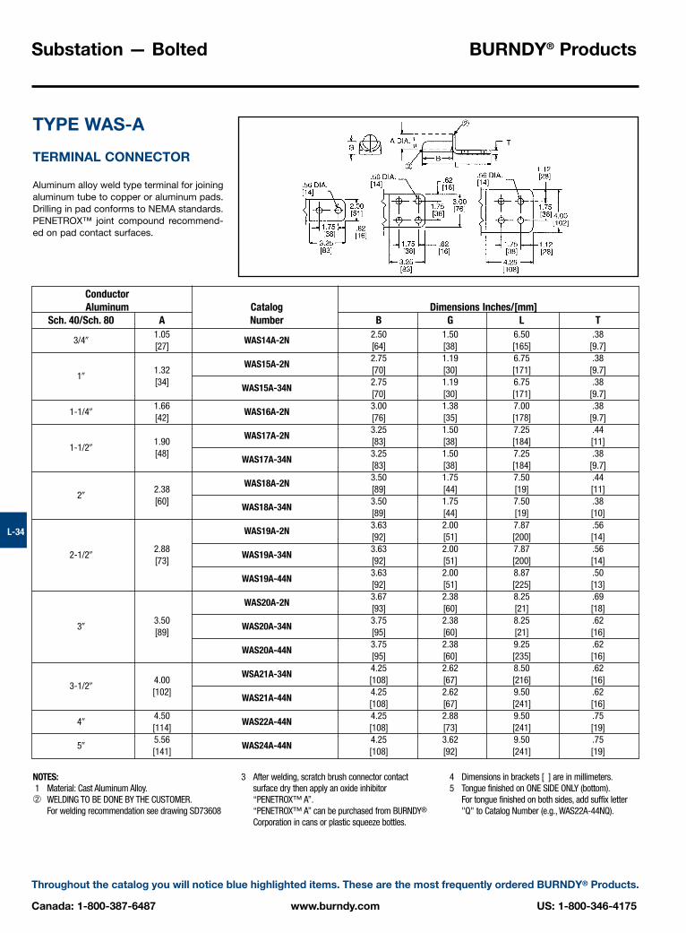
TYPE WAS-A
TERMINAL CONNECTOR
Aluminum alloy weld type terminal for joiningaluminum tube to copper or aluminum pads.Drilling in pad conforms to NEMA standards.PENETROX™ joint compound recommend-ed on pad contact surfaces.
NOTES:1 Material: Cast Aluminum Alloy.➁ WELDING TO BE DONE BY THE CUSTOMER.
For welding recommendation see drawing SD73608
3 After welding, scratch brush connector contactsurface dry then apply an oxide inhibitor“PENETROX™ A”.“PENETROX™ A” can be purchased from BURNDY®
Corporation in cans or plastic squeeze bottles.
ConductorAluminum Catalog Dimensions Inches/[mm]
Sch. 40/Sch. 80 A Number B G L T1.05 2.50 1.50 6.50 .38
3/4�[27]
WAS14A-2N[64] [38] [165] [9.7]2.75 1.19 6.75 .38
1.32WAS15A-2N
[70] [30] [171] [9.7]1�
[34] 2.75 1.19 6.75 .38WAS15A-34N
[70] [30] [171] [9.7]1.66 3.00 1.38 7.00 .38
1-1/4�[42]
WAS16A-2N[76] [35] [178] [9.7]3.25 1.50 7.25 .44
1.90WAS17A-2N
[83] [38] [184] [11]1-1/2�
[48] 3.25 1.50 7.25 .38WAS17A-34N
[83] [38] [184] [9.7]3.50 1.75 7.50 .44
2.38WAS18A-2N
[89] [44] [19] [11]2�
[60] 3.50 1.75 7.50 .38WAS18A-34N
[89] [44] [19] [10]3.63 2.00 7.87 .56
WAS19A-2N[92] [51] [200] [14]
2.88 3.63 2.00 7.87 .562-1/2�
[73]WAS19A-34N
[92] [51] [200] [14]3.63 2.00 8.87 .50
WAS19A-44N[92] [51] [225] [13]3.67 2.38 8.25 .69
WAS20A-2N[93] [60] [21] [18]
3.50 3.75 2.38 8.25 .623�
[89]WAS20A-34N
[95] [60] [21] [16]3.75 2.38 9.25 .62
WAS20A-44N[95] [60] [235] [16]4.25 2.62 8.50 .62
4.00WSA21A-34N
[108] [67] [216] [16]3-1/2�
[102] 4.25 2.62 9.50 .62WAS21A-44N
[108] [67] [241] [16]4.50 4.25 2.88 9.50 .75
4�[114]
WAS22A-44N[108] [73] [241] [19]
5.56 4.25 3.62 9.50 .755�
[141]WAS24A-44N
[108] [92] [241] [19]
4 Dimensions in brackets [ ] are in millimeters.5 Tongue finished on ONE SIDE ONLY (bottom).
For tongue finished on both sides, add suffix letter"Q" to Catalog Number (e.g., WAS22A-44NQ).

BURNDY® Products Substation — Bolted
US: 1-800-346-4175 www.burndy.com Canada: 1-800-387-6487
Throughout the catalog you will notice blue highlighted items. These are the most frequently ordered BURNDY® Products.
L-35
TYPE WASC-A-N
CENTERFORMED WELDMENT TERMINAL
Aluminum alloy weldment terminal. TypeWASC-A-N has one contact surface on thecenter line of the tube. Holes are NEMAspaced for terminating aluminum or coppermating pads. PENETROX™ joint compoundrecommended for use on contact surfaces.
For tongue finished on both sides add suffix letter "Q" toCatalog Number (e.g., WASC14A2NQ).
Fig. 1 Fig. 2 Fig. 3
Catalog Aluminum Conductor Fig. Dimensioins Inches/[mm]Number Schedule 40/80 A [mm] No. B L TWASC14A2N 3/4� 1.05 [27] 1 2.50 [64] 6.44 [164] .22 [6]WASC15A2N 1WASC15A34N
1� 1.32 [33]2
2.75 [70] 6.69 [170] .38 [10]
WASC16A2N 1WASC16A34N
1-1/4� 1.66 [42]2
3.00 [76] 7.00 [178] .38 [10]
WASC17A34N 1-1/2� 1.90 [48] 2 3.25 [83] 7.31 [186] .44 [11]WASC18A34N 2 7.56 [192]WASC18A44N
2� 2.38 [60]3
3.50 [90]8.56 [217]
.50 [13]
WASC19A2N 1WASC19A34N 2-1/2� 2.88 [73] 2 3.75 [95]
7.88 [200].56 [14]
WASC19A44N 3 8.88 [226]WASC20A2N 1WASC20A34N 3� 3.50 [89] 2 4.00 [102]
8.13 [207]
WASC20A44N 3 9.13 [232]WASC21A2N 1
.62 [16]
WASC21A34N 3-1/2� 4.00 [102] 2 4.25 [108]8.38 [213]
WASC21A44N 3 9.38 [238]WASC22A2N 1WASC22A34N 4� 4.50 [114] 2 4.25 [108]
8.38 [213].75 [19]
WASC22A44N 3 9.38 [238]WASC24A34N 2 8.50 [216]WASC24A44N
5� 5.56 [141]3
4.25 [108]9.50 [241]
.75 [19]
WASC86A44N 6� 6.63 [168] 3 4.25 [108] 9.50 [241] 1.00 [25]

Substation — Bolted BURNDY® Products
Canada: 1-800-387-6487 www.burndy.com US: 1-800-346-4175
Throughout the catalog you will notice blue highlighted items. These are the most frequently ordered BURNDY® Products.
L-36
“A” DIA.
6.00[152]
Y
1.50 DIA. [38]
.75 DIA.[19]
W
B
TYPE WG-A
WELDMENT GROUND STUD
Range-taking weldment stud for groundingAluminum tube.
Dimensions in brackets [ ] are in millimeters
Dimensioins Inches/[mm]Catalog Number Aluminum IPS A B W Y
1.315 - 2.88 3.00 1.32 8.19WG19A 1� - 2-1/2�
[33] - [73] [76] [34] [208]3.50 - 6.62 2.00 3.06 10.31
WG86A 3� - 6�[89] - [168] [51] [78] [262]