burndy grounding table of contents€¦ · burndy ® grounding us: 1-800-346-4175 canada:...
TRANSCRIPT

BURNDY® Grounding
US: 1-800-346-4175 www.burndy.com Canada: 1-800-387-6487
Blue highlighted items are industry standard and most frequently ordered.
E-1
TABLE OF CONTENTSHYGROUND® IRREVERSIBLE COMPRESSION GROUNDING
AND INSTALLATION TOOLING
Type YGIB . . . . . . . . . . E-20 - E-21
Type GSTUD-HY . . . . . . . . . . . E-22
Types YGT & YTTAG . . . . . . . . E-23
Type YG-B . . . . . . . . . . . . . . . . E-24
MECHANICAL GROUNDING
Types KC, K2C . . . . . . . . . . . . E-25
Types KC22J12T13, EQC632C, KS-DB . . . . . . . . . E-26
Types KS, GKA,KPB, CL50-1 . . . . . . . . E-26 - E-27
Type GAR . . . . . . . . . . . E-28 - E-29
Types GAR-BU & GAR 3900 Series & GAR-RB . . . . E-30
Type GAR-TC . . . . . . . . . . . . . E-31
HYGROUND® Features and Benefits . . . . . . . . . E-5 - E-6
Type YGL-C . . . . . . . . . . . . . . . . E-7
Type YGLR-C . . . . . . . . . . . . . . . E-8
Type YGHP-C . . . . . . . . . . . . . . E-9
Type YGHP-C . . . . . . . . . . . . . E-10
Type YGHC-C . . . . . . . . . . . . . E-11
Type YGC . . . . . . . . . . . . . . . . . E-12
Type YSHG . . . . . . . . . . . . . . . . E-13
Type YGHR-C . . . . . . . . . . . . . E-14
Type YGHR-C . . . . . . . . . . . . . E-15
Type YGHA . . . . . . . . . . . . . . . E-16
Type YGHS . . . . . . . . . . . . . . . E-16
Type YGA . . . . . . . . . . . . . . . . . E-17
Type YGS . . . . . . . . . . . . . . . . . E-18
Type YGF . . . . . . . . . . . . . . . . . E-19
LIGHTNING PROTECTION INFO.Basic rules for selection are:1. Must be like material to the conductor.2. Two bolts to ground rod –– minimum, for mechanical.3. Cable to cable connections can be installed with – one
bolt, two bolt, or compression.4. Cable to steel structure must have 8 in.2 contact with steel.5. Heavy duty stacks –– mechanical only.6. On all connectors with heavy duty stack rating, we must
offer 1/16� thick lead plating as an option. Reason is clos-est 25 ft. to stack opening must use lead coated product.
7. UL 96 Listing.

Grounding BURNDY®
Canada: 1-800-387-6487 www.burndy.com US: 1-800-346-4175
Blue highlighted items are industry standard and most frequently ordered.
E-2
TABLE OF CONTENTSMECHANICAL GROUNDING (Continued)
Types GC, GCM . . . . . . . . . . . . E-48
Type GL . . . . . . . . . . . . . . . . . . E-49
Type GZ . . . . . . . . . . . . . . . . . . E-49
Type GC-CT . . . . . . . . . . . . . . . E-50
Type GTC1AC34RA . . . . . . . . . E-51
Type GIE-G . . . . . . . . . . . . . . . E-52
Rail Connector . . . . . . . . . . . . . E-53
Type QGFL . . . . . . . . . . . . . . . . E-54
Type GA-H . . . . . . . . . . . . . . . . E-54
Type GRF . . . . . . . . . . . . . . . . . E-55Raised Floor Grounding
Types GP-G1, GPRT. . . . . . . . . E-56Raised Floor Grounding
Type BBB. . . . . . . . . . . . E-57 - E-58Copper BusBar
Type GD . . . . . . . . . . . . . . . . . . E-32
Type GP . . . . . . . . . . . . . . . . . . E-33
Type GK . . . . . . . . . . . . . . . . . . E-33
Type BDT BONDIT™ . . . . . . . . E-34
Water Pipe Grounding . . E-35 - E-40
Type GC-A . . . . . . . . . . . . . . . . E-41
Type GG . . . . . . . . . . . . . . . . . . E-42
Type GQ . . . . . . . . . . . . . . . . . . E-43
Type GX . . . . . . . . . . . . . . . . . . E-44
Types GRC, GRL, GCRT1/0 . . E-45
Type B . . . . . . . . . . . . . . E-46 - E-47
Types GB, GBM . . . . . . . . . . . . E-48

BURNDY® Grounding
US: 1-800-346-4175 www.burndy.com Canada: 1-800-387-6487
Blue highlighted items are industry standard and most frequently ordered.
E-3
TABLE OF CONTENTSBURNDYWeld®
BURNDYWeld®
Introduction. . . . . . . . . . . . . . . . E-60
Making a BURNDYWeld®
Connection . . . . . . . . . . . . . E-61
WELD METAL . . . . . . . . . . . . . E-62
Type BCC-1 . . . . . . . . . . . . . . . E-63
Type BCC-2 . . . . . . . . . . . . . . . E-64
Type BCC-4 . . . . . . . . . . . . . . . E-65
Type BCC-11 . . . . . . . . . . . . . . E-66
Type BCC-6 . . . . . . . . . . . . . . . E-67
Type BCC-14 . . . . . . . . . . . . . . E-67
Type BCC-7 . . . . . . . . . . . . . . . E-68
Type BCR-1 . . . . . . . . . . . . . . . E-69
Type BCR-2 . . . . . . . . . . . . . . . E-70
Type BCR-3 . . . . . . . . . . . . . . E-71
Type BCR-17 . . . . . . . . . . . . . . E-72
Type BCR-24 . . . . . . . . . . . . . . E-73
Type BCS-1 . . . . . . . . . . . . . . . E-75
Type BCS-8 . . . . . . . . . . . . . . . E-75
Type BCS-2 . . . . . . . . . . . . . . . E-76
Type BCS-9 . . . . . . . . . . . . . . . E-76
Type BCS-3 . . . . . . . . . . . . . . . E-77
Type BCS-23 . . . . . . . . . . . . . . E-78
Type BCS-4 . . . . . . . . . . . . . . . E-79
Type BCS-6 . . . . . . . . . . . . . . . E-79
Type BCS-7. . . . . . . . . . . . . . . . E-80
Type BCS-18 . . . . . . . . . . . . . . E-80
Type BCS-5 . . . . . . . . . . . . . . . E-81
Type BCRE-1 . . . . . . . . . . . . . . E-82
Type BCRE-2 . . . . . . . . . . . . . . E-83

Grounding BURNDY®
Canada: 1-800-387-6487 www.burndy.com US: 1-800-346-4175
E-4
TABLE OF CONTENTSBURNDYWeld® (Continued)
Type BCRE-3 . . . . . . . . . . . . . . E-84
Type BCRE-4 . . . . . . . . . . . . . . E-85
Type BCRE-6 . . . . . . . . . . . . . . E-86
BURNDY®
GROUNDMAX™ . . . . . E-87 - E-88
BURNDY GRIDMAX™ . . . . . . E-89
Types B-106 & B-107Handle Clamps . . . . . . . . . . E-90
B40-0106-75 Handle Attachment . . . . . . . E-90
Mold Support Clamp . . . . . . . . E-90
Vertical MagneticClamps . . . . . . . . . . . . . . . . . E-91
Horizontal & VerticalChain Clamps . . . . . . . . . . . E-91
SINGLE SHOT MOLDS
Type BCR-1 . . . . . . . . . . . . . . . E-74
Type BCR-2 . . . . . . . . . . . . . . . E-74
Type BCR-24 . . . . . . . . . . . . . . E-74
Type BCR-25 . . . . . . . . . . . . . . E-74
ACCESSORIES
B38-0330-00 Cable Clamp . . . E-92
Cable Cleaning Brush . . . . . . . E-92
Card Cloth Brush . . . . . . . . . . . E-92
Mold Cleaning Brush . . . . . . . . E-92
Mold Cleaners . . . . . . . . . . . . . E-92
Packing Material . . . . . . . . . . . E-92
BURNDYWeld™ Tool Kit . . . . E-93
BURNDYWeld™ Tools . . . . . . E-93
B38-0101-00 Rasp . . . . . . . . . E-93
B38-0309-00 Flint Ignitor . . . . E-93
Ground Rod Driving Sleeves . . . . . . . . . . E-94
Shim Stock and Adapter Sleeves . . . . . . . . . . E-94
Tips. . . . . . . . . . . . . . . . . E-95 - D96

BURNDY® GroundingHYGROUND® Compression
US: 1-800-346-4175 www.burndy.com Canada: 1-800-387-6487
Blue highlighted items are industry standard and most frequently ordered.
E-5
THE HYGROUND®
IRREVERSIBLE COMPRESSION SYSTEM
BURNDY® has developed an irreversiblecompression ground system which meetsthe most stringent safety and performancerequirements, including those of OSHA andnuclear power plant design. Performanceexcellence and long life expectancy are thesystem’s basic design guidelines. It is a com-plete system which consists of connectorsfor grid cross connections, taps, splices,cable to ground rod, ground plates and ter-minations.
Our irreversible compression ground con-nectors employ well-proven design princi-ples and technology that have been in exis-tence for over 60 years.
Connectors are just one component of ourIrreversible Compression Ground System.Installation tooling is also an integral part ofthis system. BURNDY® pioneered the com-pression connector principle and continuestoday to be the leader in compression tech-nology. Our tooling package is the mostextensive in the industry and affords the usermany options.

Canada: 1-800-387-6487 www.burndy.com US: 1-800-346-4175
Blue highlighted items are industry standard and most frequently ordered.
E-6
Grounding BURNDY®
HYGROUND® Compression
THE HYGROUND®
IRREVERSIBLE COMPRESSION SYSTEM(Continued)
Features and Benefits
• Irreversible compression.�Meets 1999 NEC code, section 250-50
and 250-64.• Material-pure wrought copper extrusions,
rod and seamless tubing––identical material to the conductor.�Completely eliminates the possibility of
corrosion due to dissimilar metals.• Heavy duty connector design.
�All connectors will carry the equivalent or greater current carrying capacity of the conductor while maintaining high mechanical strength and electrical integrity.
• Range taking design––minimum number ofconnector combinations required to installa conductor range of #6 solid to 500 kcmilplus 1/2�, 5/8�, 3/4�, and 1� ground rodsand rebar.� Inventories are kept to a minimum and
product selection is simplified.• System engineered tooling.
�Each tooling recommendation has been designed to ensure reliability of the connection.
• Irreversible compression connectors can be installed in all kinds of weather.�Eliminates costly construction delays
and enables the installer to better schedule his job.
• May be installed without special training or special tools. Y750 crimps entire range.�Low installed cost.�Simplified installation.
• Each connection can be made in less than3 minutes.�Low installed cost.�Simplified installation.
• Each connector is clearly marked with catalog number, conductor size and installation die information.�Easy and accurate identification.
• Inspection ports are provided to assureproper insertion of the conductor.�Built-in quality assurance.
• The die index number is embossed on theconnector after completion of the crimp.�Facilitates speedy inspection of
installed connectors to insure consis-tently reliable and sound connections.
• Most HYGROUND® irreversible compres-sion elements are prefilled with PENETROX™ and individually sealed in clear polyethylene sheet.�Ensures that all contact surfaces are in
the proper condition for installation.�Ensures the electrical integrity of the
finished connection by inhibiting mois-ture and contaminates from entering the contact area.
• All HYGROUND® irreversible compressionconnectors are Listed in conformance withUnderwriters Laboratories StandardUL467 and conform to applicable sectionsof the National Electrical Code.�May be used in direct burial or concrete
embedded grounding applications.• All HYGROUND® irreversible connectors
(with the exception of type YGA and YGS)have been tested successfully according to requirements of Standard IEEE 837.�Meets tough industry performance
requirements.�UPRECRIMP dies give added mechani-
cal strength. UPRECRIMP 34 for 3/4�
rod, UPRECRIMP 12 for 1/2� rod, andUPRECRIMP 58 for 5/8� rod (now includes undersized U.S. marketplace rods).
• Allows connection to most sizes of structural steel with no drilling, tapping, or welding.�Safely installed at low cost. Hot work
permits are not required to install in hazardous areas

US: 1-800-346-4175 www.burndy.com Canada: 1-800-387-6487
Blue highlighted items are industry standard and most frequently ordered.
E-7
BURNDY® GroundingHYGROUND® Compression
TYPE YGL-C
HYGRID CROSS CONNECTOR
An irreversable compression ground gridcross connector which allows adjustment ofthe compression elements prior to installa-tion. Only six connectors and four dies arerequired to install all combinations from #6solid through 500 kcmil. UL467 Listed.Acceptable for direct burial in earth and con-crete. Prefilled with PENETROX™ compoundand strip sealed.
NOTES:• Before crimping, both connector elements can
be turned on rod diameter “D” to any desiredposition.
• Clean rust and/or protective coatings from rebarprior to installation.
• When attaching connector to ground rod,ground rod must be embossed with appropriatePRECRIMP™ die. For connections that mustmeet IEEE 837 requirements UPRECRIMP - typePRE crimp dies must be used for maximumclamping retention.
ORDERING INFORMATION
1. Where a “U” or “PU” die is recommended with Y45HYPRESS™, a PT6515 adapter must be used.
2. Where a “U” or “PU” die is recommended with the Y46HYPRESS™, a PUADP-1 adapter must be used.
 Polarized die for the PAT750-18V.
UL96 Listed for Lightning Protection.
467 96
Catalog Cable to Cable Cable to Ground Rod To RebarNumber Element “A” Element “B” Element “A” Element “B” Element “A”
YGL2C2#6 Sol. (.162) – #2 Str. (.292)
{59500} – {59500} #6 Sol. (.162) – #2 Str. (.292)
YGL29C2#1 Str. (.332) – 250 kcmil (.575) {59500} – {59500}
#6 Sol. (.162) – #2 Str. (.292) 3/8� – 1/2�{98500} – {131500}
1/2� – 5/8� RodYGL29C29
#2 Str. (.292) – 250 kcmil (.575) #2 Str. (.292) – 250 kcmil (.575)#2 Str. (.292) – 250 kcmil (.575) #3 – 4 Rebar
{65500} – {131500} {65500} – {131500}YGL34C2 #6 Sol. (.162) – #2 Str. (.292) #6 Sol. (.162) – #2 Str. (.292)
5/8� – 3/4�YGL34C29 250 kcmil (.575) – 500 kcmil (.813) #2 Str. (.292) – 250 kcmil (.575) 5/8� – 3/4� Rod #2 Str. (.292) – 250 kcmil (.575)YGL34C34 250 kcmil (.575) – 500 kcmil (.813) 250 kcmil (.575) – 500 kcmil (.813)
#5 – 6 Rebar
Dimensions in brackets { } represent lightning protection conductors.
* These connectors can only be installed using the Y750,Y45, or Y46 HYPRESS™ with the recommended dies.These connectors CANNOT be installed with the Y35 andY39 HYPRESS™.
Installation Tools, Die Set Catalog Number (Number of Crimps)Catalog Y750/Y35/Y39 HYPRESS™ PAT750-18V Y45 HYPRESS™ Y46 HYPRESS™Number Element “A” Element “B” Element “A” Element “B” Element “A” Element “B” Element “A” Element “B”YGL2C2 U-0 (1) U-0 (1) U-0 (1) U-0 (1) U-0 (1) U-0 (1) U-0 (1) U-0 (1)YGL29C2 U997 (1) U-0 (1) Â U997P (1) U-0 (1) U997 (1) U-0 (1) U997 (1) U-0 (1)YGL29C29 U997 (1) U997 (1) Â U997P (1) Â U997P (1) U997 (1) U997 (1) U997 (1) U997 (1)
S998 or P998 orYGL34C2* PU998 (1) U-0 (1) PU998 (1) U-0 (1)
PU998 (1)U-0 (1)
PU998 (1)U-0 (1)
S998 or PU998 orYGL34C29* PU998 (1) U997 (1) PU998 (1) Â U997P (1)
PU998 (1)U997 (1)
PU998 (1)U997 (1)
YGL34C34* U1011 (3) U1011 (3) U1011 (3) U1011 (3) S1011 (3) S1011 (3) P1011 (3) P1011 (3)
CatalogNumber B B-B C C-C D L RYGL2C2 1.09YGL29C2
1.09 .313 .31
YGL29C29 .75 .751.66
1.66 .500 .50YGL34C2 1.09 .313
2.50.31
YGL34C292.09
1.66 .500 .50YGL34C34 1.10 1.10 2.28 2.28 .750 .75
Ground RodDia. PRECRIMP Dies1/2� UPRECRIMP 125/8� UPRECRIMP 58 U2CABT3/4� UPRECRIMP 34
IEEE-837
Grounding BURNDY®
HYGROUND® Compression
Canada: 1-800-387-6487 www.burndy.com US: 1-800-346-4175
Blue highlighted items are industry standard and most frequently ordered.
E-8
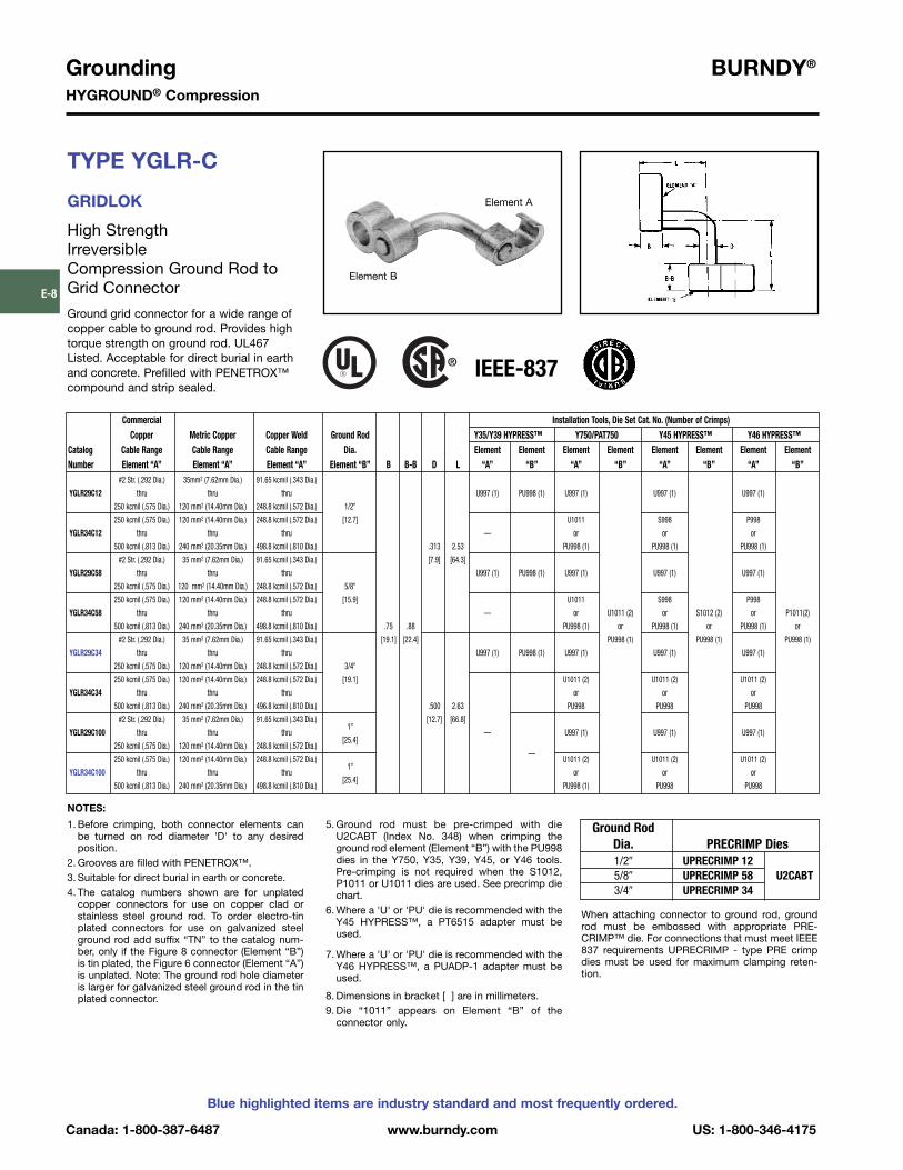
TYPE YGLR-C
GRIDLOK
High Strength Irreversible Compression Ground Rod toGrid Connector
Ground grid connector for a wide range ofcopper cable to ground rod. Provides hightorque strength on ground rod. UL467 Listed. Acceptable for direct burial in earthand concrete. Prefilled with PENETROX™compound and strip sealed.
When attaching connector to ground rod, groundrod must be embossed with appropriate PRE-CRIMP™ die. For connections that must meet IEEE837 requirements UPRECRIMP - type PRE crimpdies must be used for maximum clamping reten-tion.
NOTES:
1. Before crimping, both connector elements canbe turned on rod diameter 'D' to any desiredposition.
2. Grooves are filled with PENETROX™.3. Suitable for direct burial in earth or concrete.4. The catalog numbers shown are for unplated
copper connectors for use on copper clad orstainless steel ground rod. To order electro-tinplated connectors for use on galvanized steelground rod add suffix “TN” to the catalog num-ber, only if the Figure 8 connector (Element “B”)is tin plated, the Figure 6 connector (Element “A”)is unplated. Note: The ground rod hole diameteris larger for galvanized steel ground rod in the tinplated connector.
Element B
Element A
5. Ground rod must be pre-crimped with dieU2CABT (Index No. 348) when crimping theground rod element (Element “B”) with the PU998dies in the Y750, Y35, Y39, Y45, or Y46 tools.Pre-crimping is not required when the S1012,P1011 or U1011 dies are used. See precrimp diechart.
6. Where a 'U' or 'PU' die is recommended with theY45 HYPRESS™, a PT6515 adapter must beused.
7. Where a 'U' or 'PU' die is recommended with theY46 HYPRESS™, a PUADP-1 adapter must beused.
8. Dimensions in bracket [ ] are in millimeters.9. Die “1011” appears on Element “B” of the
connector only.
Ground RodDia. PRECRIMP Dies1/2� UPRECRIMP 125/8� UPRECRIMP 58 U2CABT3/4� UPRECRIMP 34
Commercial Installation Tools, Die Set Cat. No. (Number of Crimps)Copper Metric Copper Copper Weld Ground Rod Y35/Y39 HYPRESS™ Y750/PAT750 Y45 HYPRESS™ Y46 HYPRESS™
Catalog Cable Range Cable Range Cable Range Dia. Element Element Element Element Element Element Element ElementNumber Element “A” Element “A” Element “A” Element “B” B B-B D L “A” “B” “A” “B” “A” “B” “A” “B”
#2 Str. (.292 Dia.) 35mm2 (7.62mm Dia.) 91.65 kcmil (.343 Dia.)
YGLR29C12 thru thru thru U997 (1) PU998 (1) U997 (1) U997 (1) U997 (1)
250 kcmil (.575 Dia.) 120 mm2 (14.40mm Dia.) 248.8 kcmil (.572 Dia.) 1/2�
250 kcmil (.575 Dia.) 120 mm2 (14.40mm Dia.) 248.8 kcmil (.572 Dia.) [12.7] U1011 S998 P998
YGLR34C12 thru thru thru — or or or
500 kcmil (.813 Dia.) 240 mm2 (20.35mm Dia.) 498.8 kcmil (.810 Dia.) .313 2.53 PU998 (1) PU998 (1) PU998 (1)
#2 Str. (.292 Dia.) 35 mm2 (7.62mm Dia.) 91.65 kcmil (.343 Dia.) [7.9] [64.3]
YGLR29C58 thru thru thru U997 (1) PU998 (1) U997 (1) U997 (1) U997 (1)
250 kcmil (.575 Dia.) 120 mm2 (14.40mm Dia.) 248.8 kcmil (.572 Dia.) 5/8�
250 kcmil (.575 Dia.) 120 mm2 (14.40mm Dia.) 248.8 kcmil (.572 Dia.) [15.9] U1011 S998 P998
YGLR34C58 thru thru thru — or U1011 (2) or S1012 (2) or P1011(2)
500 kcmil (.813 Dia.) 240 mm2 (20.35mm Dia.) 498.8 kcmil (.810 Dia.) .75 .88 PU998 (1) or PU998 (1) or PU998 (1) or
#2 Str. (.292 Dia.) 35 mm2 (7.62mm Dia.) 91.65 kcmil (.343 Dia.) [19.1] [22.4] PU998 (1) PU998 (1) PU998 (1)
YGLR29C34 thru thru thru U997 (1) PU998 (1) U997 (1) U997 (1) U997 (1)
250 kcmil (.575 Dia.) 120 mm2 (14.40mm Dia.) 248.8 kcmil (.572 Dia.) 3/4�
250 kcmil (.575 Dia.) 120 mm2 (14.40mm Dia.) 248.8 kcmil (.572 Dia.) [19.1] U1011 (2) U1011 (2) U1011 (2)
YGLR34C34 thru thru thru or or or
500 kcmil (.813 Dia.) 240 mm2 (20.35mm Dia.) 496.8 kcmil (.810 Dia.) .500 2.63 PU998 PU998 PU998
#2 Str. (.292 Dia.) 35 mm2 (7.62mm Dia.) 91.65 kcmil (.343 Dia.) [12.7] [66.8]
YGLR29C100 thru thru thru1�
— U997 (1) U997 (1) U997 (1)
250 kcmil (.575 Dia.) 120 mm2 (14.40mm Dia.) 248.8 kcmil (.572 Dia.)[25.4]
250 kcmil (.575 Dia.) 120 mm2 (14.40mm Dia.) 248.8 kcmil (.572 Dia.)—
U1011 (2) U1011 (2) U1011 (2)
YGLR34C100 thru thru thru1�
or or or
500 kcmil (.813 Dia.) 240 mm2 (20.35mm Dia.) 498.8 kcmil (.810 Dia.)[25.4]
PU998 (1) PU998 PU998
IEEE-837

BURNDY® GroundingHYGROUND® Compression
US: 1-800-346-4175 www.burndy.com Canada: 1-800-387-6487
Blue highlighted items are industry standard and most frequently ordered.
E-9
TYPE YGHP-C
HYTAP™ CONNECTOR
Irreversible compression ground tap figure 6can be used as a tap connector or as a tapsplice connector. Four die sets and eight con-nectors can accommodate a conductorrange from #8 solid through 500 kcmil plus1/2�, 5/8�, and 3/4� copper bonded groundrods. UL467 Listed. Acceptable for directburial in earth and concrete. Prefilled withPENE TROX™ compound and strip sealed.
NOTES:
À When using #6 Sol. in tap, fold conductor double toimprove fill in YGHP2C2.
Á For YGHP29C29 when using 3/0 in tap, minimum run conductor is 2/0 Str.
 Where a 'U' or 'PU' die is recommended with the Y45HYPRESS™, a PT6515 adapter must be used.
à Where a 'U' or 'PU' die is recommended with the Y45HYPRESS™, a P-UADP-1 adapter must be used.
For increased rotational resistance on ground rods,pre-crimp ground rod with U2CABT die Index 348or uprecrimp dies may be used for even greaterrotation and vibration resistance on ground rods.
CABLE TO GROUND RODCABLE TO REBARCABLE TO CABLEFOR CONCRETE ENCASEDELECTRODE GROUNDINGAPPLICATIONS
Fig. 1 Fig. 2
UL96 Listed for Lightning Protection.
Installation DataÄ Die Y750/Y35 Â Ã
Catalog Fig. Accommodates Cable To Rebar Index Y39 Y45 Y46 No. ofNumber No. Run Tap Run Tap B No. HYPRESS™ PAT750-18V HYPRESS™ HYPRESS™ Crimps
YGHP2C2 1#6 Sol. (0.162) {59500} – À #6 Sol. (0.162) {#2 Str.} –
— —#2 Str. (0.292) {59500} #2 Str. (0.292) {#2 Str.}
0 U0 U0 U0 U0 1YGHP2C6W6WÇ 2
#6 Sol. (0.162) – #8 Sol. (0.128) –— —
#2 Str. (0.292) 6 Str. (0.184) Qty. 2
YGHP29C6W6WÇ 2#8 Sol. (0.128) –
#8 Sol. – 6 Str.6 Str. (0.184) Qtr. 2 #3 Rebar
YGHP29C2 1 1/0 Str. (0.372) {98500} –#4 Sol. (0.204) {#4 Sol.} – 3/8
#2 Str.250 kcmil (0.575) {131500}
#2 Str. (0.292) {#2 Str.}997 U997 Æ U997P U997 U997 1
YGHP29C26 1 1/2� – 5/8� Rod1/0 Str. (0.372) {98500} –
thr0ugh1/0 Str. – 2/0 Str.
.752/0 Str. (0.419) {98500} 1/2 [19]
YGHP29C29 Á 13/0 Str. (0.470) {131500} – #4 Rebar
3/0 Str. – 250 kcmil250 kcmil (0.575) {211500}
YGHP34C2 Å 1#4 Sol. (0.204) –
#5 Rebar —#2 Str. (0.292)
5/8YGHP34C26 Å 1
250 kcmil (0.575) {250 kcmil} –1/0 Str. (0.372) {98500} –
1/0 Str. – 2/0 Str. 998 PU998 PU998PU998 or PU998 or
1500 kcmil (0.813) {500 kcmil}2/0 Str. (0.419) {98500} S998 P998
YGHP34C29 Å 15/8� – 3/4� Rod
3/0 Str. (0.470) {131500} –through
3/0 Str. – 250 kcmil250 kcmil (0.575) {211500}
250 kcmil (0.575) –350 kcmil (0.681) –
3/41.10
YGHP34C34 Å 1 500 kcmil (0.813) #6 Rebar 350 kcmil – 500 kcmil 1011 ÅU1011 U1011 S1011 P1011 35/8� – 3/4� Rod
500 kcmil (0.843) [28]
Dimensions in brackets { } represent lightning protection conductors.
467 96
Ä Clean rust and protective coatings from rebar before con-nector installation to provide a proper ground connection.Precrimping is not required.
Å These connectors can only be installed using the Y750,Y45 or Y46 HYPRESS™ with the recommended dies.These connectors can not be installed with the Y35 andY39 HYPRESS™.
Æ Polarized die for the PAT750-18V.
Ç Not UL96/CSA.
Ground RodDia. PRECRIMP Dies1/2� UPRECRIMP 125/8� UPRECRIMP 58 U2CABT3/4� UPRECRIMP 34
IEEE-837

Grounding BURNDY®
HYGROUND® Compression
Canada: 1-800-387-6487 www.burndy.com US: 1-800-346-4175
Blue highlighted items are industry standard and most frequently ordered.
E-10
TYPE YGHP-C
HYTAP™ CONNECTOR
High Strength Copper IrreversibleCompression
Ground Rod Tap Connector
Type YGHP-C irreversible compressionground tap figure 6 can be used as a groundrod tap connector for both continuous run andtapping applications. An open groove allowsground rod to be connected to a continuousrun or tap. The second groove is for a tap only.Prefilled with PENETROX™ E and stripsealed. UL467 Listed for direct burial in earth or concrete.
Features and Benefits
• Tap (A) accepts a continuous run on tap conductorTap (B) accepts a tap conductor only.�One connector style can be used for
many applications, reducing number of connectors in inventory.
• Material is high conductivity wrought copper extrusion, identical material to the conductor.�High-conductivity copper minimizes
resistance and voltage drop. Eliminatesthe possibility of corrosion due to dissimiliar metals.
• System engineered tooling.�The tooling recommendation has been
designed to ensure a reliable, depend-able connection every time.
• The die index number is embossed onconductor after completion of crimp.�Faciliates speedy inspection of installed
connectors to insure consistently reli-able and dependable connections.
NOTE: A 12� bend radius is recommended for the conductor.• Use PUADP-1 with ‘U’-dies in Y46.s See tooling section in Master Catalog for complete tool
and die listing.+ Either tap position may be left void when fewer than (2)
conductors are used.
SINGLE TAP CONTINUOUS RUN CONTINUOUS RUN AND TAP
PATENTEDTAP (A)
TAP (B)
PREFILLED WITHPENETROX™ E
DIE INDEX AND CONDUCTORINFORMATION
“THIRD HAND”
• Prefilled with PENETROX™ E and individ-ually sealed in clear polyethylene sheet.�Ensures the electrical integrity of the
finished connection by inhibiting mois-ture and contaminates from entering the contact area. Maintains long-term high-conductivity.
• UL467 Listed.�May be used in direct burial or concrete
embedded grounding applications.Provides quality assurance to recog-nized industry NEC standards from an independent party.
• “Third Hand” constrains conductors whileinstaller completes crimp. Included witheach connector.�Simplifies installation, reducing
installed cost.
n Ground rod must be precrimped with die U2CABT (IndexNo. 348).For even greater rotational resistance use UPRECRIMPdie.For Galvanized Steel Rods order YGHP58C2W-2TN.
s Installation ToolingY35/Y750/PAT750 Y46 •
Catalog Ground Dimensions Die No. of Die No. of DieNumber Rod Dia. n Tap Conductor + H B W No. Crimps No. Crimps IndexYGHP58C2W-2 #2 Sol. - #6 Sol. Copper
1/2� - 5/8� (1) Continuous run and (1) Tap or 1.90� .75� .94� U997 (1) U997 (1) 997YGHP58C2W-2TN
up to (2) taps may be connected.
IEEE-837

BURNDY® GroundingHYGROUND® Compression
US: 1-800-346-4175 www.burndy.com Canada: 1-800-387-6487
Blue highlighted items are industry standard and most frequently ordered.
E-11
Commercial Copper Cable Range/ Installation DataGround Rod Ç Stranded Copper Die Y750/Y35/ À Á No.
Catalog to Copper Cable Cable Range Index PAT750/Y39 Y45 Y46 ofNumber Run Tap Run Tap A B No. HYPRESS™ HYPRESS™ HYPRESS™ Crimps
#6 Sol. (0.162)YGHC2C2 #2 Str. (0.292)
#6 Sol. (0.162) 10 mm2 (4.12 mm) 10 mm2 (4.12 mm) 1.16 0.75C U-C U-C U-C 1
1/4� Rod Æ#2 Str. (0.292) 35 mm2 (7.62 mm) 35 mm2 (7.62 mm) [30] [19]
1 Str. (0.328){98500}
#6 Sol. (0.162)
YGHC26C2 2/0 Str. (0.419){#6 Sol.} 35 mm2 (7.62 mm) 10 mm2 (4.12 mm) 1.41 0.75
0 U-O U-O U-O 1{98500}
#2 Str. (0.292) 70 mm2 (10.9 mm) 35 mm2 (7.62 mm) [36] [19]
3/8� Rod Æ{#2 Str.}
1 Str. (0.328){98500}
1 Str. (0.328)
YGHC26C26 2/0 Str. (0.419){98500} 35 mm2 (7.62 mm) 35 mm2 (7.62 mm) 1.54 0.75
0 U-O U-O U-O 1{98500}
2/0 Str. (0.419) 70 mm2 (10.9 mm) 70 mm2 (10.9 mm) [39] [19]
3/8� Rod Æ{98500}
3/0 Str. (0.470){3/0 Str.}
6 Sol. (0.162)
YGHC29C26 250 kcmil (0.575){59500} 95 mm2 (12.5 mm) 10 mm2 (4.12 mm) 1.97 0.75
997 U997 U997 U997 1{250 kcmil}
2/0 Str. (0.419) 120 mm2 (14.4 mm) 70 mm2 (10.9 mm) [50] [19]
1/2� or 5/8� Rod Æ{98500}
3/0 Str. (0.470)YGHC29C29 250 kcmil (0.575)
3/0 Str. (0.470) 95 mm2 (12.5 mm) 95 mm2 (12.5 mm) 2.06 0.88997 U997 U997 U997 1
1/2� or 5/8� Rod Æ250 kcmil (0.575) 120 mm2 (14.4 mm) 120 mm2 (14.4 mm) [52] [22]
300 kcmil (0.630){300 kcmil}
#6 Sol. (0.162)
YGHC34C26 Å 500 kcmil (0.813){59500} 150 mm2 (16 mm) 10 mm2 (4.12 mm) 2.42 0.88
1011 U1011 S1011 P1011 2{500 kcmil}
2/0 Str. (0.419) 240 mm2 (20.35 mm) 70 mm2 (10.9 mm) [62] [22]
3/4� Rod Æ{98500}
300 kcmil (0.630) 3/0 Str. (0.470) 150 mm2 (16 mm) 95 mm2 (12.5 mm) 2.67 0.88YGHC34C29 Å
500 kcmil (0.813) 250 kcmil (0.575) 240 mm2 (20.35 mm) 120 mm2 (14.4 mm) [66] [22]1011 U1011 S1011 P1011 2
300 kcmil (0.630) 300 kcmil (0.630) 150 mm2 (16 mm) 150 mm2 (16 mm) 2.91 1.1YGHC34C34 Å
500 kcmil (0.813) 500 kcmil (0.813) 240 mm2 (20.35 mm) 240 mm2 (20.35 mm) [74] [28]1011 U1011 S1011 P1011 3
TYPE YGHC-C
HYTAP™ CONNECTOR
Irreversible compression ground tap figure“C” connectors. Accommodates all cable combinations from #6 solid through 500kcmil. “C”- shaped opening permits placingtwo continuous parallel cables into conduc-tor groove. UL 467 Listed. Acceptable fordirect burial in earth or concrete. Prefilledwith PENE TROX™ compound and stripsealed. Certain sizes are also UL467 Listedand CSA Certified for wire to ground rod.
NOTES:À Where a “U” or “PU” die is recommended with
the Y45 HYPRESS™, PT6515 adapter must beused.
Á Where a “U” or “PU” die is recommended withthe Y46 HYPRESS™, a PUADP-1 adaptermust be used.
3. Listed under UL486A for copper wire connec-tors
4. Dimensions in brackets [ ] are in millimeters.
UL96 Listed for Lightning Protection. 467 96
Dimensions in brackets { } represent lightning protection conductors.
5. In referencing connectors without PENETROX™oxide inhibitor add suffix “NP” to the end of theCatalog Number.
Å These connectors can only be installed usingthe Y750, Y45 or Y46 HYPRESS™ with the rec-om mended dies.These connectors cannot be installed with theY35 and Y39 HYPRESS™.
Æ Ground rod to copper cable is UL 467 Listedfor direct burial in earth and concrete.
IEEE-837
Ç For ground rod to wire applications, ground rodmust be precrimped, see above table forappropriate precrimp dies.
Ground RodDia. PRECRIMP Dies1/2� UPRECRIMP 125/8� UPRECRIMP 58 U2CABT3/4� UPRECRIMP 34
New!
Ground Rod to W
ire
UL467 Listed and
CSA Certified
for Dire
ct Buria
l
Grounding BURNDY®
HYGROUND® Compression
Canada: 1-800-387-6487 www.burndy.com US: 1-800-346-4175
Blue highlighted items are industry standard and most frequently ordered.
E-12
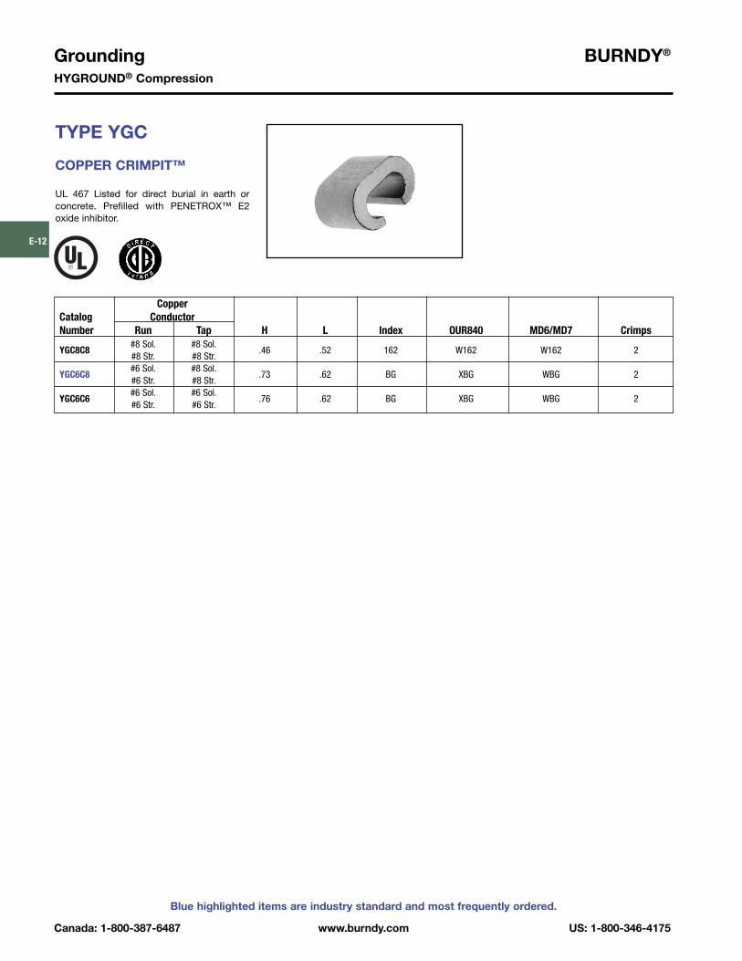
TYPE YGC
COPPER CRIMPIT™
UL 467 Listed for direct burial in earth or concrete. Prefilled with PENETROX™ E2 oxide inhibitor.
CopperCatalog ConductorNumber Run Tap H L Index OUR840 MD6/MD7 Crimps
#8 Sol. #8 Sol.YGC8C8
#8 Str. #8 Str..46 .52 162 W162 W162 2
#6 Sol. #8 Sol.YGC6C8
#6 Str. #8 Str..73 .62 BG XBG WBG 2
#6 Sol. #6 Sol.YGC6C6
#6 Str. #6 Str..76 .62 BG XBG WBG 2

BURNDY® GroundingHYGROUND® Compression
US: 1-800-346-4175 www.burndy.com Canada: 1-800-387-6487
Blue highlighted items are industry standard and most frequently ordered.
E-13
TYPE YSHG
HIGH STRENGTH COPPER IRREVERSIBLECOMPRESSION
Double H-Tap Connector
Type YSHG Double H-Tap grounding seriesis comprised of five connectors designed toaccommodate wire range sizes #14 through500 kcmil, including ground rod sizes: 3/4�,1�, and rebar sizes: #6, #8 and #9. Prefilledwith PENETROX™ E2 and strip sealed. Features and Benefits
• UL467 Listed.�Suitable for direct burial in earth
or concrete.• Material is high conductivity
copper extrusion.�Minimizes resistance, eliminates
corrosion due to dissimilar metals.
* NOTE: Not for use on 1� steel ground rod.† Use PUADP-1 adapter.
Fig. 1 Fig. 2 Fig. 3
• Grooves are prefilled with PENETROX™ E2oxide inhibitor and individually sealed.� Inhibits moisture and contaminants
ensuring electrical integrity.
Tooling IndexCatalog Fig. Conductor Sizes (number of crimps) Emboss- W T LNumber No. Main Tap 1 Tap 2 Tap 3 PAT750/Y750 Y46 ment �.06 �.04 �.06
#9 & #8 Rebar, 1� [25] Ground 3.22 1.70 2.44YSHG4429 3
Rod250 - 2 PYFR (2) K-R
[82] [43] [62]#6 Rebar, 1� [25] Cu Clad
* YSHG3931 2 Ground Rod, 3/4� Ground Rod 4/0 - 1/0 1 - 6 2 - 14 PYFR (2) K-R2.97 1.50 2.34
500 - 350 kcmil Copper[75] [38] [59]
#6 Rebar, 3/4� [19] Ground Rod P1104 (2) 2.43 1.15 2.44YSHG3434 1
400 - 250 kcmil Copper 400 - 4/0 U1104 (4)
†U1104 (4)1104
[62] [29] [62]#6 Rebar, 3/4� [19] Ground Rod P1104 (2) 2.23 1.31 2.44
YSHG3429 2400 - 4/0 kcmil Copper
3/0 - 1/0 1 - 4 8 - 14 U1104 (4)†U1104 (4)
1104[57] [33] [62]

Grounding BURNDY®
HYGROUND® Compression
Canada: 1-800-387-6487 www.burndy.com US: 1-800-346-4175
Blue highlighted items are industry standard and most frequently ordered.
E-14
TYPE YGHR-C
HYTAIL™
High Strength Irreversible Compression Ground Rod Tap Connectors
High torque strength ground rod connectors.Accommodates a wide range of copper conductors to ground rod. UL467 Listed.Acceptable for direct burial in earth or con-crete. Prefilled with PENETROX™ compoundand strip sealed.
NOTES:• The catalog numbers shown are for unplated copper
connectors for use on copper clad or stainless steelground rod. To order electro-tin plated connectors for useon galvanized steel ground rod add suffix “TN” to the cat-alog number. Note: The ground rod hole diameter is largerfor galvanized steel ground rod in the tin plated connector.
¬ Ground rod must be pre-crimped with die U2CABT (IndexNo. 348) when the PU998 dies are used in the Y750, Y35,Y39, Y45, or Y46 tools. Pre-crimping is not required whenthe P1011, S1011, S1012 or U1011 dies are used. UPRE-CRIMP dies may be used for additional mechanical resist-ance on ground rods.
Á Where a PU998 die is recommended with the Y45HYPRESS™, a PT6515 adapter must be used.
 Where a PU998 die is recommended with the Y46HYPRESS™, a PUADP-1 adapter must be used.
à These die numbers do not appear on the connector.* These connectors can only be installed using the Y750,
Y45 or the Y46 HYPRESS™ with the recommended dies.These connectors CAN NOT be installed with the Y35 andY39 HYPRESS™. When attaching connector to ground rod,ground rod must be embossed with appropriate PRE-CRIMP™ die. For connections that must meet IEEE 837requirements UPRECRIMP - type PRE crimp dies must beused for maximum clamping retention.
CatalogNumber H BYGHR26C12 1.94� [49.3]YGHR26C58 1.97� [50.0]YGHR26C34 2.19� [55.6]YGHR26C100 2.55� [56.2]YGHR29C12 1.94� [49.3]
.88�YGHR29C58 2.14� [54.4]YGHR29C34 2.19� [55.6]
[22.4]
YGHR29C100 2.45� [62.2]YGHR34C58 2.14� [54.4]YGHR34C34 2.44� [62.0]YGHR34C100 2.70� [68.6]
Catalog Commercial Copper Nominal Ground Installation Tools, Die Set Catalog Number (Number of Crimps)Number Cable Range Rod Dia. PAT750/Y750/Y35/Y39 ¬ Y45 HYPRESS ¬ Y46 HYPRESS ¬YGHR26C12 1/2� [12.7] S1012 (2)YGHR26C58 #2 Str. (.292 Dia.) 5/8� [15.9] Ã
YGHR26C34 through 3/4� [19.0] PU998 (1) 2/0 Str. (.419 Dia.) S1011 (2) S1012 (2)
YGHR26C100* 1� [25.4]PU998 (1)
YGHR29C12 1/2� [12.7] U1011 (2) S1012 (2) P1011 (2)YGHR29C58 #4/0 Str. (.528 Dia.) 5/8� [15.9] Ã Ã Ã
YGHR29C34 through 3/4� [19.0] PU998 (1) PU998 (1) PU998 (1)250 kcmil (.575 Dia.) S1011 (2) S1012 (2) ®
YGHR29C100* 1� [25.4]Ã PU998 (1)
YGHR34C58 300 kcmil (.630 Dia.) 5/8� [15.9] S1012 (2)YGHR34C34* through 3/4� [19.0]
ÃPU998 (1)
YGHR34C100* 500 kcmil (.813 Dia.) 1� [25.4] S1011 (2) P1011 (2)
IEEE-837

BURNDY® GroundingHYGROUND® Compression
US: 1-800-346-4175 www.burndy.com Canada: 1-800-387-6487
Blue highlighted items are industry standard and most frequently ordered.
E-15
TYPE YGHR-C
HYTAIL™
High Strength Irreversible Compression Ground Rod Tap Connectors
Type YGHR-C irreversible compressiongrounding connector is engineered specifical-ly for the Telecommunications Industry for (1, 2 or 3) #2 solid, tinned or bare conductortaps. UL467 Listed. Acceptable for direct bur-ial in earth or concrete. BURNDY® hasdesigned this connector to meet the stringentrequirements of OSHA, the National ElectricCode (NEC), UL, and the TelecommunicationsIndustry. Performance and long life are thisconnector’s basic design guidelines.
Features and Benefits
• Tap side 1, 2 or 3 conductors.�One connector style can be used for
many applications.• Material is high conductivity wrought
copper extrusion, identical material tothe conductor.�High-conductivity copper minimizes
resistance and voltage drop. Eliminatesthe possibility of corrosion due to dissimilar metals.
• System engineered tooling.�Each tooling recommendation has
been designed to provide a reliable,dependable connection.
• Contact BURNDY® for other ground rod diameters.* PU998 and U1011 die sets require PUADP-1 adapter for
use in the Y46 HYPRESS™.Tap positions may be left void when fewer than (3) con-ductors are used.
+ To order electro-tin plated connector for use on galvanizedsteel ground rod add suffix -”TN” to the catalog number.
NOTE: The ground rod hole diameter is larger for galvanizedsteel ground rod in the tin plated connector.
TAPTAPRUN RUN
AND
• The die index number is embossed onconnector after completion of crimp.�Facilitates speedy inspection of installed
connectors to ensure consistently reliable and dependable connections.
• Prefilled with PENETROX™ and individuallysealed in clear polyethylene sheet.�Ensures the electrical integrity of the
finished connection by inhibiting mois-ture and contaminates from entering the contact area. Maintains long-term high-conductivity.
• UL 467 Listed. Acceptable for direct burial.�May be used in direct burial or concrete
embedded grounding applications.Provides quality assurance to recog-nized industry NEC standards from an independent party.
† Ground rod must be precrimped with die U2CABT (IndexNo. 348) when PU998 die set is used in the Y35, Y750 orY46.
s HYPRESS™ tools. For even greater mechanical resistanceuse UPRECRIMP 58 dies.
** The Y750 utilizes PU dies and the U1011 die. The Y35only uses PU998 die set.
NOTE: A 12� bend radius is recommended for the conductor.
Installation ToolingPAT750/Y35/Y750** Y46*
Catalog Ground Rod Die No. of Die No. of DieNumber + Diameter • Tap Conductor s No. Crimps No. Crimps Index
PU998† (1)#2 Sol. Copper 1, 2, or 3
PU998† (1)U1011 (2) 998 or
YGHR58C2W-3 5/8�may be connected P998 (1) 1011
U1011 (2)P1011 (2)

Grounding BURNDY®
HYGROUND® Compression
Canada: 1-800-387-6487 www.burndy.com US: 1-800-346-4175
Blue highlighted items are industry standard and most frequently ordered.
E-16
TYPE YGHA
HYLUG™
Heavy Duty IrreversibleCompression Terminals
Heavy duty HYLUG™ irreversible compres-sion terminals designed not only to carryshort circuit load, but to also withstand highmechanical stress. Each conductor elementhas an inspection probe hole to ensure proper cable insertion. UL467 Listed.Acceptable for direct burial in earth or con-crete. UL486A Listed. Prefilled with PENE -TROX™ compound and strip sealed.
TYPE YGHS
HYLINK™
Heavy Duty IrreversibleCompression Terminals
Heavy duty HYLINK™ ground splicedesigned not only to carry short circuit load,but to also withstand high mechanical stress.Each conductor element has an inspectionprobe hole and a center stop to ensure proper cable insertion. UL467 Listed.Acceptable for direct burial in earth or concrete. UL486A Listed. Prefilled with PENETROX™ compound and strip sealed.
¬ Where a “U” or “PU” die is recommended with the Y45HYPRESS™, a PT6515 adapter must be used.
¬ Where a “U” or “PU” die is recommended with the Y45HYPRESS™, a PT6515 adapter must be used.
INSPECTION PROBE HOLESFOR CABLE STOP
KNURLEDRINGS
IEEE-837
IEEE-837
Installation Tools, Die Set Catalog Number,Catalog and (Number of Crimps)Number Copper Conductor Size HYPRESS™ Y35/Y39/Y45 ¬ /Y46 /Y750 /PAT750 B C L TYGHA2C-2N 2 str. U1CRT (1) .75 .97 4.21 .26YGHA25-2N 1/0 str. U27RT (1) .83 .91 4.60 .19YGHA26-2N 2/0 str. U28RT (1) .83 .97 4.38 .26YGHA27-2N 3/0 str. U29RT (1) 1.18 1.08 4.94 .29YGHA28-2N 4/0 str. U30RT (2) 1.18 1.22 4.94 .30YGHA29-2N 250 kcmil U31RT (2) 1.18 1.28 4.94 .34YGHA31-2N 350 kcmil U34RT (2) 1.18 1.62 5.00 .43YGHA34-2N 500 kcmil U36RT (3) 1.48 1.72 5.42 .40
Installation Tools, Die Set Catalog Number,Catalog and (Number of Crimps)Number Copper Conductor Size HYPRESS™ Y35/Y39/Y45 ¬ /Y46 /Y750 /PAT750 B LYGHS2C 2 str. U1CRT (1) .75 1.73YGHS25 1/0 str. U27RT (1) .83 1.89YGHS26 2/0 str. U28RT (1) .83 1.89YGHS27 3/0 str. U29RT (1) 1.18 2.59YGHS28 4/0 str. U30RT (2) 1.18 2.59YGHS29 250 kcmil U31RT (2) 1.18 2.59YGHS31 350 kcmil U34RT (2) 1.18 2.59YGHS34 500 kcmil U36RT (3) 1.48 3.19
Á Where a “U” or “PU” die is recommended with the Y46HYPRESS™, a PUADP-1 adapter must be used.
Á Where a “U” or “PU” die is recommended with the Y46HYPRESS™, a PUADP-1 adapter must be used.

BURNDY® GroundingHYGROUND® Compression
US: 1-800-346-4175 www.burndy.com Canada: 1-800-387-6487
Blue highlighted items are industry standard and most frequently ordered.
E-17
TYPE YGA
HYLUG™
Grounding IrreversibleCompression Terminals
Irreversible compression HYLUG™ Groundterminal specifically designed for groundingapplications. Each connector has an inspec-tion probe hole to ensure proper cable inser-tion. UL467 Listed. Acceptable for direct burial in earth or concrete. UL486A Listed. Prefilled with PENETROX™ compound and strip sealed.
¬ Where a “U” or “PU” die is recommended with the Y45HYPRESS™, a PT6515 adapter must be used.
Fig. 1 Fig. 2
Installation Tools, Die Set Cat. No., and(number of crimps)
Mechanical HydraulicY35/Y39/Y45/PAT750 ¬
Copper Y2MR MD7-34R OUR840 /Y46 /Y750Catalog Fig. Conductor Die # (# of Die # (# of Die # (# of Die # (# of StudNumber No. Size crimps) crimps) crimps) crimps) Size B C L T E
W8CVT (2)YGA8C-TC10 2 8 sol./8 str. Red (4)
X8CRT (2)U8CRT (2) #10 .81 .41 1.57 .08 —
W8CVT (2)YGA8C-TC14 2 8 sol./8 str. Red (4)
X8CRT (2)U8CRT (2) 1/4 .81 .44 1.69 .08 —
W8CVT (2)YGA8C-TC516 2 8 sol./8 str. Red (4)
X8CRT (2)U8CRT (2) 5/16 .81 .51 1.75 .06 —
W8CVT (2)YGA8C-2N 1 8 sol./8 str. Red (4)
X8CRT (2)U8CRT (2) 1/2 .81 .71 4.09 .05 1.75
W5CVT (2)YGA6C-TC10 2 6 sol./6 str. Blue (4)
X5CRT (2)U5CRT (2) #10 1.12 .42 1.89 .09 —
W5CVT (2)YGA6C-TC14 2 6 sol./6 str. Blue (4)
X5CRT (2)U5CRT (2) 1/4 1.12 .45 2.02 .08 —
W5CVT (2)YGA6C-TC516 2 6 sol./6 str. Blue (4)
X5CRT (2)U5CRT (2) 5/16 1.12 .51 2.08 .07 —
W5CVT (2)YGA6C-2TC38E2G1 1 6 sol./6 str. Blue (4)
X5CRT (2)U5CRT (2) 3/8 1.12 .58 3.42 .06 .75
W5CVT (2)YGA6C-2N 1 6 sol./6 str. Blue (4)
X5CRT (2)U5CRT (2) 1/2 1.12 .83 4.40 .12 1.75
W2CVT (2)YGA2C-2TC38 1 2 sol./2 str. Brown (4)
X2CRT (2)U2CRT (2) 3/8 1.25 .60 3.48 .12 1.00
W2CVT (2)YGA2C-2N 1 2 str. Brown (4)
X2CRT (2)U2CRT (2) 1/2 1.22 .81 4.71 .12 1.75
W25VT (4)YGA25-2N 1 1/0 str. —
X25RT (4)U25RT (2) 1/2 1.35 .81 4.91 .12 1.75
W26VT (4)YGA26-2N 1 2/0 str. —
X26RT (4)U26RT (2) 1/2 1.45 .81 4.89 .12 1.75
W28VT (4)YGA28-2N 1 4/0 str. —
X28RT (4)U28RT (2) 1/2 1.57 1.00 5.06 .14 1.75
YGA29-2N 1 250 kcmil — W29VT (4) U29RT (2) 1/2 1.57 1.09 5.16 .16 1.75YGA34-2N 1 500 kcmil — W34VT (4) U34RT (4) 1/2 2.20 1.52 5.94 .23 1.75
Á Where a “U” or “PU” die is recommended with the Y46HYPRESS™, a PUADP-1 adapter must be used.

Grounding BURNDY®
HYGROUND® Compression
Canada: 1-800-387-6487 www.burndy.com US: 1-800-346-4175
Blue highlighted items are industry standard and most frequently ordered.
E-18
TYPE YGS
HYLINK™
Grounding IrreversibleCompression Splices
Irreversible compression HYLINK™ groundsplices specifically designed for groundingapplications. Each conductor element has aninspection probe hole and a center stop toensure proper cable insertion. UL467 Listed.Acceptable for direct burial in earth or concrete. UL486A Listed. Prefilled with PENETROX™ compound and strip sealed.
¬ Where a “U” or “PU” die is recommended with the Y45HYPRESS™, a PT6515 adapter must be used.
Á Where a “U” or “PU” die is recommended with the Y46HYPRESS™, a PUADP-1 adapter must be used.
® Use “X” with OUR840, “W” with MD6/MD7.
Installation Tools, Die Set Catalog Number, and(Number of Crimps)
Mechanical HydraulicCopper Y2MR MD7-34R OUR840 Y35/Y39/Y45¬
Catalog Conductor Die # (# of Die # (# of Die # (# of /Y46 /Y750/PAT750Number Size Crimps) Crimps) Crimps) Die # (# of Crimps) B LYGS8C #8 sol./str. — X8CRT, W8CRT, W8CVT Â U8CRT (2) .78 1.75YGS6C #6 sol./str. — X5CRT, W5CRT, W5CVT Â U5CRT (2) 1.09 2.38
W2CVT (2)YGS2C 2 str. Brown (4)
X2CRT (2)U2CRT (2) 1.22 2.67
W25VT (4)YGS25 1/0 str. —
X25RT (4)U25RT (2) 1.35 2.97
W26VT (4)YGS26 2/0 str. —
X26RT (4)U26RT (2) 1.45 3.13
W28VT (4)YGS28 4/0 str. —
X28RT (4)U28RT (2) 1.57 3.37
YGS29 250 kcmil — W29VT (4) U29RT (2) 1.57 3.37YGS34 500 kcmil — W34VT (4) — U34RT (4) 2.20 4.63

BURNDY® GroundingHYGROUND® Compression
US: 1-800-346-4175 www.burndy.com Canada: 1-800-387-6487
Blue highlighted items are industry standard and most frequently ordered.
E-19
TYPE YGF
GROUNDING PLATE
The irreversible compression ground plate isdesigned to withstand the rigors of concreteconstruction. The ground plates are made ofhigh strength, high-conductivity cast copperalloy body with a pure wrought copper compression element. In addition to thetapped NEMA size holes and spacing on theface, the plate comes with a tapped hole onthe underside for ease of positioning prior topouring the concrete. UL467 Listed.Acceptable for direct burial in earth or concrete. Prefilled with PENETROX™ compound and strip sealed.
NOTES:¬ This tapped hole may be used to position the grounding
plate on a threaded rod prior to placement of the concrete.
ORDERING INFORMATION¬ Where a “U” or “PU” die is recommended
with the Y45 HYPRESS™, a PT6515adapter must be used.
Fig. 1
Fig. 2
IEEE-837
¬ 3/8-16 thread with 1.00 EFF. Thread is standard. If otherthread is required, add appropriate Code No. to CatalogNo. for desired thread.-50 (1/2 -13, .94 EFF. Thread), -62 (5/8 -11, .94 EFF.Thread) and -75 (3/4 -10, .81 EFF. Thread)Example: YGF34-4N-50 is YGF34-4N with 1/2 -13 Thread
Plastic plugs are provided to keep dirt out of the threadedholes until the attachment of grounding terminals.
CatalogNumber Fig. No. C D H L T YYGF29-2N 1 2.00 3.25 3.62 5.78 1.31 2.00YGF29-4N 2 3.25 3.25 3.62 5.78 1.31 2.00YGF34-2N 1 2.00 3.25 4.62 5.40 1.31 2.19YGF34-4N 2 3.75 3.75 4.62 5.90 1.31 2.19
Installation Tools,Die Set Cat. No., and(number of crimps)
Catalog Copper Tapped Holes HYPRESS™Number Conductor Range Size Hole Centers PAT750/Y750/Y35/Y39 Y45 ¬ Y46 YGF29-2N 2 - 250 kcmil 1/2 - 13 1-3/4 U997 (1) U997 (1) U997 (1)YGF29-4N 2 - 250 kcmil 1/2 - 13 1-3/4 U997 (1) U997 (1) U997 (1)YGF34-2N* 250 - 500 kcmil 1/2 - 13 1-3/4 U1011 (3) S1011 (2) P1011 (2)YGF34-4N* 250 - 500 kcmil 1/2 - 13 1-3/4 U1011 (3) S1011 (2) P1011 (2)
Á Where a “U” or “PU” die is recommendedwith the Y46 HYPRESS™, a PUADP-1adapter must be used.
* These connectors can only be installedusing the Y750, Y45 or Y46 HYPRESS™with recommended dies. These connec-tors CAN NOT be installed with the Y35 orY39 HYPRESS™.

Grounding BURNDY®
HYGROUND® Compression
Canada: 1-800-387-6487 www.burndy.com US: 1-800-346-4175
Blue highlighted items are industry standard and most frequently ordered.
E-20
NOTES:1. Terminal conector to be ordered separately. When I-
beam connector is used with type “YGHA” terminal, theconnection meets IEEE 837-1989 requirements. YGA-2N,YA-2N and other BURNDY® 2-hole NEMA copper termi-nals are suitable.
2. Order “TMHG” Terminal Mounting Hardware Kit sepa-rately. Kit consists of 2 studs, 2 flat washers, 2 lock-washers and 2 hex nuts.
3. Using the 1/4 hex key wrench, screw the stud into theconnector until stud bottoms out in connector. Install a“YGHA” terminal, flat washer, lockwasher and hex nutonto stud. Tighten and torque to 480 pound-inches.
TYPE YGIB
GROUNDLINK™ CONNECTOR
An irreversible compression ground connec-tion which allows attachment to a structuralsteel standard (angled) or wide flange (para llel) beam. Installed with a required5-piece die set, Catalog PIBEAMKIT orUIBEAMKIT. Die index 1105. GROUNDLINK™connectors are made of high-conductivitywrought copper and come pre-filled withPENETROX™ E compound and strip sealed.Order terminal mounting hardware separately.
NOTE: Use TMHG-92 to double stack lugs.
Fig. 1
Fig. 2
Connector shipped with thread protection studs only. OrderTMHG kits separately.
1.84 In. Minimum flange depth.3.06 In. Minimum flange width.
Standard Beams (Flange Angled) use YGIBS
Wide Flange Beams (Flange Parallel) use YGIBW
TERMINAL MOUNTING HARDWARE“T” Ref. Maximum Terminal Pad Thickness
Y46 Seriesuse PIBEAMKIT
Y750 Seriesuse UIBEAMKIT
2 Hole NEMASpacing
à Ã
IEEE-837
à Dimensions shown reflect the minimum dimensionsrequired on a beam to properly install the I-beam connector.
5. To correctly determine the appropriate YGIB connector touse based on flange thickness, order either YGIBGAUGE1or YGIBKIT1 (KIT1 contains wiremike).
Catalog Number “T”
TMHG-42 .42
TMHG-92 .92

BURNDY® GroundingHYGROUND® Compression
US: 1-800-346-4175 www.burndy.com Canada: 1-800-387-6487
Blue highlighted items are industry standard and most frequently ordered.
E-21
TYPE YGIB(Continued)
GROUNDLINK™ CONNECTOR
Copper i-BeamConductor Fig. Flange Suggested Terminals
Range Catalog Number No. “L” “J” Thickness Copper Conductor Terminal “T” Ref.#2 Str. AWG YGHA2C-2N .26
YGIBS28-338-2N 1 3.001/0 Str. AWG YGHA25-2N .19
2 - 4/0 AWG .250�2/0 Str. AWG YGHA26-2N .26
YGIBW28-338-2N 2 3.00 to4/0 Str. AWG YGHA28-2N .30
YGIBS34-338-2N 1.338�
250 kcmil YGHA29-2N .34250 - 500 kcmil
YGIBW34-338-2N 26.00
500 kcmil YGHA34-2N .40#2 Str. AWG YGHA2C-2N .26
YGIBS28-400-2N 1 3.001/0 Str. AWG YGHA25-2N .19
2 - 4/0 AWG .338�2/0 Str. AWG YGHA26-2N .26
YGIBW28-400-2N 2 3.00 to4/0 Str. AWG YGHA28-2N .30
YGIBS34-400-2N 1.400�
250 kcmil YGHA29-2N .34250 - 500 kcmil
YGIBW34-400-2N 26.00
500 kcmil YGHA34-2N .40#2 Str. AWG YGHA2C-2N .26
YGIBS28-462-2N 1 3.001/0 Str. AWG YGHA25-2N .19
2 - 4/0 AWG.400�
2/0 Str. AWG YGHA26-2N .26YGIBW28-462-2N 2 3.00 to
4/0 Str. AWG YGHA28-2N .30YGIBS34-462-2N 1 1/2 - 13
.462�250 kcmil YGHA29-2N .34
250 - 500 kcmilYGIBW34-462-2N 2
6.00500 kcmil YGHA34-2N .40
#2 Str. AWG YGHA2C-2N .26YGIBS28-550-2N 1 3.00
1/0 Str. AWG YGHA25-2N .192 - 4/0 AWG 4.62�
2/0 Str. AWG YGHA26-2N .26YGIBW28-550-2N 2 3.00 to
4/0 Str. AWG YGHA28-2N .30YGIBS34-550-2N 1
.550�250 kcmil YGHA29-2N .34
250 - 500 kcmilYGIBW34-550-2N 2
6.00500 kcmil YGHA34-2N .40
#2 Str. AWG YGHA2C-2N .26YGIBS28-613-2N 1 3.00
1/0 Str. AWG YGHA25-2N .192 - 4/0 AWG .550�
2/0 Str. AWG YGHA26-2N .26YGIBW28-613-2N 2 3.00 to
4/0 Str. AWG YGHA28-2N .30250 - 500 kcmil YGIBW34-613-2N 2 6.00 500 kcmil YGHA34-2N .40
#2 Str. AWG YGHA2C-2N .26YGIBS28-675-2N 1 3.00
1/0 Str. AWG YGHA25-2N .192 - 4/0 AWG .613�
2/0 Str. AWG YGHA26-2N .26YGIBW28-675-2N 2 3.00 to
4/0 Str. AWG YGHA28-2N .30YGIBS34-675-2N 1
.675�250 kcmil YGHA29-2N .34
250 - 500 kcmilYGIBW34-675-2N 2
6.00500 kcmil YGHA34-2N .40

Grounding BURNDY®
HYGROUND® Compression
Canada: 1-800-387-6487 www.burndy.com US: 1-800-346-4175
Blue highlighted items are industry standard and most frequently ordered.
E-22
TYPE GSTUD-HY
VERSITAIL™
Structural Steel GroundingConnector
INSTALLATION
1. Weld the VERSITAIL™ to the steel member.
2. Select the proper connector for your specific application.
a. FOR COMPRESSION CONNECTORSSelect the proper BURNDY® “YGHP,”connector. Clean the conductor, join theVERSITAIL™ and the grounding con-ductor together with the recommendedtool and die set, then crimp the connec-tor over the knurled area of the VERSI-TAIL™.
b. FOR MECHANICAL CONNECTORSSelect the properly sized BURNDY®
connector. Clean the conductor, thenapply PENETROX™ E oxide inhibitingcompound on the contact area forincreased effectiveness and service life.Put the connector over the knurled areaof the VERSITAIL™ and apply the rec-om mended torque value for correctinstal lation.
SPECIFICATIONS
• Low Carbon, hot rolled steel.• Pure copper plated finish.
FEATURES
• The VERSITAIL™ may be welded to steelsurfaces quickly and easily with normal construction equipment.
• The VERSITAIL™ eliminates costly diskgrinding and the need to expose virginmetal. The welding process burns throughthe oxidation and “scale” to establish excellent electrical grounding continuity.
• The VERSITAIL™ may be installed by thewelder in the field or at the steel fabricatorbased on customer preference.
• The VERSITAIL™ pure copper coating overlow carbon, hot rolled steel is compatiblewith standard welding processes. No toxic gasses are generated.
• The VERSITAIL™ knurled surface is copper plated and specifically designed toensure excellent mechanical gripping andelectrical integrity for BURNDY® compres-sion and mechanical connectors in all grounding applications.
• The VERSITAIL™ may be installed duringadverse weather conditions thus eliminat-ing costly construction delays.
BENEFITS
Low installation cost.• No drilling . . . No cleaning . . .• No special preparation
* This is the equivalent rating for continuous service. Largerconductors may be connected using both compression andbolted connectors in potential ground fault applications.
A (STOCKDia.)
KNURLEDEND
B (Dia. OVER KNURL)
T
(FLATTENINGRESULTANT)
1.25[32]
TYPICALLETTERING
2.19[56]
L
45°
ElectricalEquivalent
Nom. Dimensions CopperCatalog Rod A B L T Conductor SizeNumber Size In. [mm] In. [mm] In. [mm] In. [mm] (AWG)*GSTUD14HY 1/4� .25 [6.3] .26 [6.6] 4.81 [122.2] .19 [4.8] #6GSTUD38HY 3/8� .38 [9.7] .39 [9.9] 5.81 [147.6] .25 [6.4] #3GSTUD916HY 5/8� .56 [14.2] .57 [14.5] 5.68 [144.3] .38 [9.7] 1/0GSTUD34HY 3/4� .75 [19.0] .76 [19.3] 5.81 [147.6] .51 [13.0] 4/0

BURNDY® GroundingHYGROUND® Compression
US: 1-800-346-4175 www.burndy.com Canada: 1-800-387-6487
Blue highlighted items are industry standard and most frequently ordered.
E-23
TYPES YGT & YTTAG
STATIC GROUNDING RECEPTACLE
Type YGT static grounding receptacles aredesigned for static grounding of equipment.The receptacle is connected to the groundgrid with HYGROUND® compression connectors and finished flush with surface toprovide a permanent corrosion proofgrounding point.
* When using U or PU dies with Y46 HYPRESS™, a PUADP-1adapter is required.
NOTES:1. Ground rod must be pre-crimped with U2CABT die set
when PU998 die is used or for even higher mechanicalresistance use special UPRECRIMP dies on ground rods.
2. Pre-crimping of ground is not necessary when P1011 dieis used. Install YGHR or YGLR on hub Y. Hub Z is insertedinto 1/2” rigid conduit. The conduit is driven into earth toprovide support and provide correct level of receptacleprior to cement pour.
Type YTTAG CombinationStatic Grounding Receptacleand Aircraft Tie Down Bar
Type YGT StaticGrounding Receptaclewith Cover
Fig. 1 Fig. 2
Catalog Figure DimensionsNumber Number * HYGROUND® Connector H D Y Dia. Z Dia. TD
YGT275 1 Select suitable YGHR or 5.5 2.75 .75 .56 —YGLR for 3/4� ground rod and
YTTAG388 2 sized to ground conductor. 6.5 4.75 .75 .56 4.3

Grounding BURNDY®
HYGROUND® Compression
Canada: 1-800-387-6487 www.burndy.com US: 1-800-346-4175
Blue highlighted items are industry standard and most frequently ordered.
E-24
TYPE YG-B
BUS BAR CONNECTOR
BURNDY’s YG14B2TC2C6C CompressionBus Bar Connector is ideally suited for cellu-lar tower applicatons and is easier to usethan exothermic connections. This high con-duc tivity wrought copper connector allowsattachment of the ground conductor to theground bus with just one crimp using theBURNDY® Y750 HYPRESS™ HydraulicCompression tool and the U1105 die set.This exclusive patent pending design allowsthe user to attach #2 AWG sol./str. and/or #6sol./str. copper conductor to 1/4� thick cop-per bus bar. This connection is suitable using(1) or (2) conductors for power, groundingand bonding applictions. UL Listed to bothUL486 and UL467 (suitable for direct burial)ensures that this connector will meet the rig-ors of either application. Prefilled with PENE -TROX™ E compound and strip sealed.
Ground Bar Bus Bar InstallationCatalog Number Fig No. Thickness Tap Conductors Tooling Die No. No. of Crimps
YG14B2TC2C6C 1 1/4” #2 Sol./and/or Str. Copper#6 Sol./and/or Str. Copper
PAT750, Y750 U1105 1
YG14B2TC2C2C* 2 1/4” #2#2
PAT750, Y750 U1105 1
4/0 AWG Str. to 1/0YG14BTC28 3 1/4”
AWG Str. CopperPAT750, Y750 U1105 1
NOTE: Suitable for use with either (1) or (2) conductors(excluding YG14BTC26 and YG14BTC28).
* For continuous uncut conductor applications.
Fig. 1 Fig. 2
Fig. 3

BURNDY® GroundingMechanical
US: 1-800-346-4175 www.burndy.com Canada: 1-800-387-6487
Blue highlighted items are industry standard and most frequently ordered.
E-25
MECHANICALGROUNDING CONNECTORSMore than 60 years of technological innova-tion has made BURNDY® mechanical ground-ing connectors one of the most widely used,highly respected lines in the industry. There isvirtually no grounding application problemthat this diversified line cannot help solve.
TYPES KC, K2C
SERVIT POST™
For Copper Cable to Flat
SERVIT POST™ used to ground one or twocables to steel structures, fence posts, trans-formers. Also used to tap one or two cablesfrom bus bar. One-wrench installation.
KC K2C
All BURNDY® mechanical grounding con-nectors have been designed for easy instal-lation and for outstanding durability. Only thefinest high copper alloys are used in theirmanufacture, ensuring top performanceunder the most extreme environmental con-ditions.
† For 1 conductor.‡ For 1 or 2 conductors.Add “NSP” suffix to have connector supplied w/split lock-washer and nut.
UL467 Listed for direct burial applications inearth or concrete.
Catalog Number Conductor StudType KC † Type K2C ‡ Stranded Solid Diameter B CFx CFy D H HHKC15 K2C15 3/8 1/2KC15B1 K2C15B1
12 - 9 12 - 8 1/4 - 207/8
1/2 3/81
5/8 7/8
KC17 K2C17 3/8 1/2KC17B1 K2C17B1
10 - 7 10 - 6 1/4 - 207/8
5/8 7/161
7/8 1
KC20 K2C20 13/32 5/8KC20B1 K2C20B1
10 - 5 10 - 4 5/16 - 1827/32
11/16 1/21
7/8 1-1/8
KC22 K2C22 15/32 5/8KC22B1 K2C22B1
10 - 3 10 - 2 3/8 - 1631/32
3/4 5/81-1/8
1 1-1/4
KC23 K2C23 15/32 5/8KC23B1 K2C23B1
8 - 2 10 - 1 3/8 - 1631/32
13/16 5/81-1/8
1 1-3/8
KC25 K2C25 9/16 3/4KC25B1 K2C25B1
2 - 1/0 2 - 2/0 1/2 - 131-1/16
15/16 3/41-1/4
1-1/8 1-5/8
KC26 K2C26 17/32 3/4KC26B1 K2C26B1
2 - 2/0 2 - 3/0 1/2 - 131-1/16
1 7/81-1/4
1-3/8 1-7/8
KC28 K2C28 3/4 1KC28B1 K2C28B1
1 - 4/0 1 - 4/0 5/8 - 111-1/4
1-1/2 1-3/161-1/2
1-3/4 2-1/4
KC31 K2C31 3/4 1KC31B1 K2C31B1
1 - 350 — 5/8 - 111-1/4
1-11/16 1-3/81-1/2
2-1/4 2-7/8
KC34 K2C34 1 1-1/4KC34B1 K2C34B1
3/0 - 500 — 3/4 - 101-1/2
2 1-5/81-3/4
2-3/8 3-1/4

Grounding BURNDY®
Mechanical
Canada: 1-800-387-6487 www.burndy.com US: 1-800-346-4175
Blue highlighted items are industry standard and most frequently ordered.
E-26
TYPE KS
SERVIT®
For Copper
UL467 Listed for direct burial applications inearth or concrete. Compact, high-strength,high copper alloy SERVIT® split-bolt hasfree-running threads and easy to grip wrenchflats. Highly resistant to cracking and corrosion.
TYPES KC22J12T13,EQC632C
TRANSFORMER GROUNDCONNECTORS
For Copper
Fits all standard EEI NEMA distribution transformers as a tank grounding terminal.
Both, one-wrench installation.
Type EQC632C Type KC22J12T13Stud Size = 1⁄2� - 13
.6
Catalog Number RangesKC22J12T13 8 Sol. - 2 Sol.KC26 2 Sol. - 2/0 Str.KC34J12T13 3/0 - 500 Str.EQC632C 8 Sol. - 2 Str.
Catalog Copper Conductor Range Rebar w/ (1) RecommendedNumber Cross Flats L W (Sol. - Str.) No. 8 Sol. Cu Torque (In. Lb.)KS15 .50 .85 .38 12 AWG - 8 AWG N/A 80KS17 .63 1.14 .45 8 AWG - 6 AWG N/A 165KS20 .69 1.20 .51 8 AWG - 4 AWG N/A 165KS22 .75 1.50 .60 6 AWG - 3 AWG N/A 275KS23 .82 1.54 .62 6 AWG - 2 AWG N/A 275KS25 .94 1.77 .73 4 AWG - 1/0 N/A 385
2 AWG - 2/0 #3KS26 1.05 1.94 .82
6 AWG - 8 AWG Str./Sol. (3/8�)385
KS27 1.36 1.86 1.17 1 AWG - 3/0 N/A 5001 AWG - 250 kcmil #4
KS29 1.36 2.07 1.176 AWG - 8 AWG Str./Sol. (1/2�)
650
1/0 AWG - 350 kcmil #5KS31 1.70 2.51 1.41
6 AWG - 8 AWG Str./Sol. (5/8�)650
2/0 AWG - 500 kcmil #6KS34 1.82 2.79 1.48
6 AWG - 8 AWG Str./Sol. (3/4�)825

BURNDY® GroundingMechanical
US: 1-800-346-4175 www.burndy.com Canada: 1-800-387-6487
Blue highlighted items are industry standard and most frequently ordered.
E-27
TYPE GKAFor Copper
UL467 Listed for direct burial applications inearth or concrete. One-piece forged bodyconstruction insures mechanical integrity inan underground environment. Supplied witha stainless steel headless screw.
TYPE KPBFor Copper
UL467 Listed for direct burial in earth or con-crete. UL486 listed. This exclusiveBURNDY® design accommodates #10 - #4copper where continuous conductor runs are preferable.
1. To be assembled with TMH322 stainless steel hardware kit.Ordered separately.
TYPE CL50-1
COPPER LAY-IN QIKLUG™
For Copper
The Lay-In QIKLUG™ is manufactured fromhigh strength pure electrolytic copper toensure maximum strength and conductivity.UL467 Listed for direct burial in earth or con-crete. The open-faced design allows for fastlay-in of the conductor without the need forcutting or breaking.
CatalogNumber Range Stud HoleKPB4CG1 #10 - #4 CU #10 1
1. To be assembled with TMH322SS stainless steel hardwarekit. Ordered separately.
Catalog Number Cable Range B C H J K LGKA8C 1 #10 Sol. - #8 Str. .31 .38 .58 #10 - 32 .21 .81GKA4C 2 #14 Sol. - #4 Str. .46 .54 .71 5/16 - 24 .28 1.13
2. To be assembled with TMH 323 stainless steel hardwarekit. Ordered separately.
Stainless Steel Screw
Catalog Wire RangeNumber Copper Stud HoleCL50-1 #14 - #4 CU #10CL50-1TN* #14 - #4 CU #10
*-TN Version is tin plated. Commonly used for solar panelgrounding.

Grounding BURNDY®
Mechanical
Canada: 1-800-387-6487 www.burndy.com US: 1-800-346-4175
Blue highlighted items are industry standard and most frequently ordered.
E-28
TYPE GAR
• Wire to Rebar• Fence Post Grounding
Connector• Wire to Pipe
For Parallel or 90° Copper Cable Connectionto Rod or Pipe with the Same Connector
High copper alloy ground connector for join-ing a range of cable, parallel or at rightangles to rod or tube. Especially good forfence posts. High copper alloy cast bodywith DURIUM™ U-bolts, nuts and lockwash-ers, permit entire connection to be buried inground or concrete without danger of corrosion.• One-wrench installation.• UL467 Listed.• Acceptable for direct burial.
Catalog ConductorNumber Tube I.P.S. Rod Size or O.D. Range Rebar Size Cable H J WGAR114C 8 Sol. - 4 Str.GAR1126 1/4 1/2 — 4 Sol. - 2/0 Str. 2-1/2 1-7/8GAR1129 2/0 Sol. - 250GAR644C 8 Sol. - 4 Str.
3/8
GAR6426 #5 (5/8�) - 4 Sol. - 2/0 Str. 2-7/8 2-1/8GAR6429
3/8 5/8 - 3/4#6 (3/4�) 2/0 Sol. - 250
GAR6434 300 - 500 3-1/2 1/2 2-1/2GAR144C 8 Sol. - 4 Str. 2-3/4GAR1426 #7 (7/8�) - 4 Sol. - 2/0 Str. 3/8 2-3/8GAR1429
1/2 - 3/4 7/8 - 1#8 (1�) 2/0 Sol. - 250
3
GAR1434 300 - 500 3-3/4 1/2 2-3/4GAR154C 8 Sol. - 4 Str.GAR1526 #9 (1-1/8�) - 4 Sol. - 2/0 Str.
2-7/83/8 2-5/8
GAR15291 1-1/8 - 1-1/4
#10 (1-1/4�) 2/0 Sol. - 250 3-3/8GAR1534 300 - 500 4-1/2 1/2GAR164C 8 Sol. - 4 Str.GAR1626 4 Sol. - 2/0 Str. 3-1/2 3/8 3GAR1629
1-1/4 1-3/8 - 1-1/2 #11 (1-3/8�)2/0 Sol. - 250
GAR1634 300 - 500 4-1/4 1/2 3-3/8GAR174C 8 Sol. - 4 Str.GAR1726 4 Sol. - 2/0 Str. 4 3/8 3-1/4GAR1729
1-1/2 1-5/8 - 1-7/8 —2/0 Sol. - 250
GAR1734 300 - 500 4-5/8 1/2 2-5/8GAR184C 8 Sol. - 4 Str.GAR1826 4 Sol. - 2/0 Str.
4-1/43/8 3-3/4
GAR18292 2 - 2-3/8 —
2/0 Sol. - 250 4-1/2GAR1834 300 - 500 5-1/4 1/2 4-1/8GAR194C 8 Sol. - 4 Str.GAR1926 4 Sol. - 2/0 Str. 5 3/8 4-1/4GAR1929
2-1/2 2-1/2 - 2-7/8 —2/0 Sol. - 250
GAR1934 300 - 500 5-5/8 1/2 4-5/8
New!
Rebar to W
ire
UL Listed and
CSA Certified
for Dire
ct Buria
l
Wire to Rebar
Wire Parallel to PipeWire at Right Angle to Pipe

BURNDY® GroundingMechanical
US: 1-800-346-4175 www.burndy.com Canada: 1-800-387-6487
Blue highlighted items are industry standard and most frequently ordered.
E-29
TYPE GAR(Continued)
FENCE POST GROUNDING CONNECTOR
Contact BURNDY® for additional pipe and wire size combinations not shown.
Catalog ConductorNumber Tube I.P.S. Rod Size or O.D. Range Cable H J WGAR204C 8 Sol. - 4 Str.GAR2026 4 Sol. - 2/0 Str. 5-5/8 3/8 4-3/4GAR2029
3 3 - 3-1/22/0 Sol. - 250
GAR2034 300 - 500 6-3/8 1/2 5-1/4GAR214C 8 Sol. - 4 Str.GAR2126 4 Sol. - 2/0 Str. 6-1/4 3/8 5-3/8GAR2129
3-1/2 3-1/2 - 42/0 Sol. - 250
GAR2134 300 - 500 6-3/4 1/2 5-3/4GAR224C 8 Sol. - 4 Str.GAR2226 4 Sol. - 2/0 Str. 6-3/8 3/8 5-7/8GAR2229
4 4 - 4-1/22/0 Sol. - 250
GAR2234 300 - 500 6-7/8 1/2 6-1/4GAR244C 8 Sol. - 4 Str.GAR2426 4 Sol. - 2/0 Str. 7-3/4
3/8 6-7/8
GAR24295 —
2/0 Sol. - 250GAR2434 300 - 500 8-5/8
1/2 7-1/4
GAR8629 6 — 2/0 Sol. - 250 8-13/16 1/2 8-3/8

Grounding BURNDY®
Mechanical
Canada: 1-800-387-6487 www.burndy.com US: 1-800-346-4175
Blue highlighted items are industry standard and most frequently ordered.
E-30
TYPES GAR-BU AND GAR3902 SERIES
GROUND CONNECTORS
Type GAR-BU is a high-conductivity copperground connector for connecting a small tomedium range copper ground conductor towater pipe as well as structural and reinforc-ing rod shapes. Universal acceptance of several sizes of cylindrical shapes makes thissuitable for industrial construction and main-tenance work as well as cathodic protection.Cable clamp swivels to permit parallelgrounding of one pipe or 90° degree cablerun for grounding several parallel pipes.Single wrench installation. UL467 Listed and CSA certified.
TYPE GAR-RBFor Reinforcement Bar
* Type GAR-BU is supplied with DURIUM™ silicon bronzehardware and is listed for direct burial.
UL467 listed for direct burial in earth or concrete.
Features and Benefits
• Cable clamp swivels at 90°.�Permits parallel grounding of one pipe
or a 90° cable run for grounding severalparallel pipes.
• One-wrench installation.�Simplified installation.
• DURIUM™ silicon bronze hardware (-BUSeries)*.�Long lasting corrosion resistance and
acceptable for direct burial in earth or concrete.
• UL467 Listed.�Provides quality assurance to recog-
nized industry NEC standards from an independent party.
*
Catalog RecommendedNumber * Cable Range IPS Size O.D. Range H J W Tightening TorqueGAR3902-BU 1/2� - 1� .840 - 1.32 3.50 3.25GAR3903-BU 1-1/4� - 2� 1.66 - 2.38 4.00 4.25GAR3904-BU 2-1/2� - 3-1/2� 2.88 - 4.00 6.50 6.00GAR3905-BU 4� - 5� 4.50 - 5.56 7.50 7.50GAR3906-BU
#4 - 4/0 AWG6� 6.62 8.50
3/8� - 168.62
240 in. - lbs.
GAR3907-BU 8� 8.62 10.00 10.62GAR3908-BU 10� 10.75 12.00 12.75GAR3909-BU 12� 12.75 14.00 14.75GAR3902 1/2� - 1� .840 - 1.32 3.50 3.25GAR3903 1-1/4� - 2� 1.66 - 2.38 4.00 4.25GAR3904 2-1/2� - 3-1/2� 2.88 - 4.00 6.50 6.00GAR3905 4� - 5� 4.50 - 5.56 7.50 7.50GAR3906
#4 - 4/0 AWG6� 6.62 8.50
3/8� - 168.62
240 in. - lbs.
GAR3907 8� 8.62 10.00 10.62GAR3908 10� 10.75 12.00 12.75GAR3909 12� 12.75 14.00 14.75
Catalog Copper ConductorNumber Rebar IPS Size O.D. Range Rod Min. Max.GAR644C-RB #3 - 6 (.375 - .750) 3/8 .625 - .75 5/8 - 3/4 8 Sol. 4 Str.

BURNDY® GroundingMechanical
US: 1-800-346-4175 www.burndy.com Canada: 1-800-387-6487
Blue highlighted items are industry standard and most frequently ordered.
E-31
TYPE GAR-TC
WATER PIPE GROUND CONNECTOR
Type GAR-TC is a high-conductivity copperground connector that features a pre-drilledpad, allowing a 2-hole compression terminalto be directly connected to water pipe as wellas structural and reinforcing rod shapes.Universal acceptance of several sizes ofcylindrical shapes makes this suitable forindustrial construction and maintenancework as well as telecommunications ground-ing. Terminal may be mounted parallel, 45° or90° degrees to the pipe. Acceptable fordirect burial.
Features and Benefits
• Large, smooth connector contact areabetween pipe and ground clamp�Provides large surface contact area
to maximize contact area between connector and pipe.
• The GAR-TC mounting pad permits parallel, 45° or 90° angle connections to the pipe.�Provides maximum flexibility for
field installation.• Pre-drilled pad for (2) 3/8� bolts on
1� centers.�Allows direct mounting of (2) hole
compression terminals up to 750 kcmil to pipe.
¬ Add suffix “-TNET” for electro-tin plated connector andelectro-tin plated DURIUM™ silicon bronze hardware. Tinplated catalog number includes mounting hardware forsecond bolt hole.
TMH-289 includes (1) 38 x 125 HEB, (1) 38 CHEN, (1) 38SW and (2) 38 FW. Order separately.
Fig. 1
Fig. 2
PATENTED
MOUNTING PADFOR (2) 3/8�BOLTS - 1� L
J MOUNTING PADDURIUM 3/8�SILICON BRONZEHARDWARE
• DURIUM™ silicon bronze hardware.�Provide long lasting corrosion resist-
ance acceptable for direct burial inearth or concrete.
• One-wrench installation.�Simplified installation.
• UL467 Listed.�Provides quality assurance to recog-
nized industry NEC standards from an independent party. Type GAR-TC isacceptable for direct burial
PIPE Dia.
CAST HIGH COPPER ALLOY SADDLECOMPRESSION LUG WITH PADFOR (2) 3/8� Dia. BOLTSON 1� CENTERS. 750 KCMIL MAX.
Catalog Fig. Accommodates RecomendedNumber No. I.P.S. O.D. Size H J W Tightening TorqueGAR3902TC 1 1/2� - 1� .840 - 1.32 3.50 3.75GAR3903TC 1 1-1/4� - 2� 1.66 - 2.38 4.00 4.75GAR3904TC 1 2-1/2� - 3-1/2� 2.88 - 4.00 6.50 3/8� - 16 6.50 240 in.-lbs.GAR3905TC 1 4� - 5� 4.50 - 5.56 7.50 8.00GAR3906TC 1 6� 6.62 8.50 9.12GAR3907TC 2 8� 8.62 10.00 11.25GAR3908TC 2 10� 10.75 12.00 3/8� - 16 13.25 240 in.-lbs.GAR3909TC 2 12� 12.75 14.00 15.25
NOTE: Clean pipe surface beneath saddle until virgin metalis exposed, install GAR-TC ground connector and formaximum conductivity, apply PENETROX® E oxideinhibiting compound around perimeter of the saddle.

Grounding BURNDY®
Mechanical
Canada: 1-800-387-6487 www.burndy.com US: 1-800-346-4175
Blue highlighted items are industry standard and most frequently ordered.
E-32
TYPE GD
CABLE TO ROD/TUBEGROUND CONNECTOR
For Two Copper Cables to Rod or Tube
High copper alloy ground connector for join-ing a range of two parallel cables to rod orpipe. Especially good for grounding fenceposts. High copper alloy cast body with DURIUM™ U-bolts, nuts, and lockwashersmake the GD suitable for burial in ground orconcrete. One-wrench installation. UL467Listed. Acceptable for direct burial in earth or concrete.
Complies with NFPA 78-86 HEAVY DUTY stacks.(Order: LD for lead plating for HEAVY DUTY stack applications.)
Catalog ConductorNumber Tube I.P.S. Rod Size or O.D. Range Cable H J WGD1526 4 Sol. - 2/0 Str.GD1529
1 1-1/8 - 1-1/42/0 Sol. - 250
3-3/8 2-5/8
GD1626 4 Sol. - 2/0 Str. 3GD1629
1-1/4 1-3/8 - 1-1/22/0 Sol. - 250
3-1/23/8
GD174C 8 Sol. - 4 Str.GD1726 4 Sol. - 2/0 Str. 4
3-1/4
GD17291-1/2 1-5/8 - 1-7/8
2/0 Sol. - 250GD1734 300 - 500 4-5/8 1/2 3-5/8GD184C 8 Sol. - 4 Str.GD1826 4 Sol. - 2/0 Str. 4-3/8 3/8 3-3/4GD1829
2 2 - 2-3/82/0 Sol. - 250
GD1834 300 - 500 5-3/8 1/2 4-1/8GD194C 8 Sol. - 4 Str.GD1926 4 Sol. - 2/0 Str. 3/8 4-1/4GD1929
2-1/2 2-1/2 - 2-7/82/0 Sol. - 250
5
GD1934 300 - 500 1/2 4-5/8GD204C 8 Sol. - 4 Str.GD2026 4 Sol. - 2/0 Str. 5-5/8 3/8 4-7/8GD2029
3 3 - 3-1/22/0 Sol. - 250
GD2034 300 - 500 6-3/8 1/2 5-1/4GD214C 8 Sol. - 4 Str.GD2126 4 Sol. - 2/0 Str. 6-1/4 3/8 5-3/8GD2129
3-1/2 3-1/2 - 42/0 Sol. - 250
GD2134 300 - 500 6-7/8 1/2 5-3/4GD224C 8 Sol. - 4 Str.GD2226 4 Sol. - 2/0 Str. 6-3/8 3/8 5-7/8GD2229
4 4 - 4-1/22/0 Sol. - 250
GD2234 300 - 500 6-7/8 1/2 6-1/4

BURNDY® GroundingMechanical
US: 1-800-346-4175 www.burndy.com Canada: 1-800-387-6487
Blue highlighted items are industry standard and most frequently ordered.
E-33
TYPE GP
GROUND CONNECTOR
For Two Copper Cables to Rod or Pipe
High copper alloy ground connector for join-ing a range of parallel cables perpendicular torod, pipe or column. Also used with onegroove for run, the other for tap to equipment.High copper alloy cast body and DURIUM™ U-bolts, nuts, and lockwashers make the GPsuitable for direct burial in the ground or concrete. One-wrench installation. UL467Listed. Acceptable for direct burial in earth or concrete.
TYPE GK
GROUND CONNECTOR
For Three Copper Cables to Rod or Pipe
High copper alloy ground connector for join-ing three equal cables to rod or tube. Cablegrooves take a wide range of cable. High copper alloy cast body and DURIUM™ U-bolts, nuts, and lockwashers make the GKsuitable for direct burial in soil or concrete.One-wrench installation. UL467 Listed.Acceptable for direct burial in earth or concrete.
Catalog ConductorNumber Tube I.P.S. Rod Size or O.D. Range Cable H J WGP114C 8 Sol. - 4 Str.GP1126 1/4 1/2 4 Sol. - 2/0 Str. 1-7/8GP1129 2/0 Sol. - 250 2-1/2GP644C 8 Sol. - 4 Str.
3/8
GP6426 4 Sol. - 2/0 Str. 2-1/8GP6429
3/8 5/8 - 3/42/0 Sol. - 250 2-7/8
GP6434 300 - 500 3-1/2 1/2 2-1/2GP144C 8 Sol. - 4 Str. 2-3/4GP1426 4 Sol. - 2/0 Str. 38 2-3/8GP1429
1/2 - 3/4 7/8 - 13/0 Sol. - 250
3
GP1434 300 - 500 3-3/4 1/2 2-3/4GP164C 8 Sol. - 4 Str.GP1629
1-1/4 1-5/82/0 Sol. - 250
3-1/2 3
GP1726 1-1/2 1-7/8 4 Sol. - 2/0 Str. 4 3-1/4GP184C 8 Sol. - 4 Str. 4-1/8 3/8GP1826
2 2-3/84 Sol. - 2/0 Str. 4-3/8
3-11/16
GP2026 3 3-1/2 4 Sol. - 2/0 Str. 5-1/2 4-13/16GP2226 4 4-1/2 4 Sol. - 2/0 Str. 6-3/8 5-13/16
Catalog ConductorNumber Tube I.P.S. Rod Size or O.D. Range Cable H J WGK114C 8 Sol. - 4 Str. 2-1/2GK1126 1/4 1/2 4 Sol. - 2/0 Str. 2-1/2
3/82-3/4
GK1129 2/0 Sol. - 250 1/2 3-3/8GK644C 8 Sol. - 4 Str. 2-5/8GK6426 4 Sol. - 2/0 Str. 2-7/8
3/83
GK64293/8 5/8 - 3/4
2/0 Sol. - 250 3-1/2GK6434 300 - 500 3-1/2
1/24
GK1426 4 Sol. - 2/0 Str. 2-3/4 38 3-1/4GK1429 1/2 - 3/4 7/8 - 1 2 Sol. - 250 3-7/8GK1434 300 - 500
3-3/4 1/24-3/8
GK1526 4 Sol. - 2/0 Str. 3-3/8 3/8 3-1/2GK1529
1 1-1/8 - 1-1/42/0 Sol. - 250 3-3/4 1/2 4-1/8
GK1626 4 Sol. - 2/0 Str. 3-1/2 3/8 3-7/8GK1629
1-1/4 1-3/8 - 1-1/22/0 Sol. - 250 4-1/4 1/2 4-1/2
GK1726 4 Sol. - 2/0 Str. 4 3/8 4-1/8GK1729
1-1/2 1-5/8 - 1-7/82/0 Sol. - 250 4-5/8 1/2 4-3/4
GK1826 4 Sol. - 2/0 Str. 4-1/4 3/8 4-5/8GK1829
2 2 - 2-3/82/0 Sol. - 250 4-3/8 1/2 5-1/8
GK1926 4 Sol. - 2/0 Str. 5 3/8 5-1/8GK1929
2-1/2 2-1/2 - 2-7/82/0 Sol. - 250 5 1/2 5-5/8

Grounding BURNDY®
Mechanical
Canada: 1-800-387-6487 www.burndy.com US: 1-800-346-4175
Blue highlighted items are industry standard and most frequently ordered.
E-34
TYPE BDT
BONDIT™ INTERSYSTEMBONDING CONNECTOR
House Mounted or Meter Socket Mounted
Designed to meet the requirements of 2008NEC Article 250.94 “Bonding for OtherSystems.” Corrosion-resistant stainless steelset screws. Accepts main ground wire (#2-#8)and up to 4 intersystem wires (#6-#14). Samedesign can be mounted directly to the metersocket or mounted to the house. Innovativedesign does not damage meter socket andwill not void warranty.
Catalog Number: BDT1
Features & Benefits
• Made in the USA!• Meets Intersystem Bonding Requirements:
NEC2008 250.94• One connector does it all• House mount or meter socket mount• Incorporates proven BURNDY® SERVIT
POST™ design• Stainless steel set screws• Accepts main ground wire (#2-#8), up to 4
intersystem wires (#6-#14)
• Easily mounts to meter box during newinstallation or can be wall mounted
• Easy to follow instructions included• Does not damage meter socket; no worries
about damaging the paint or voiding war-ranties
• Easily installed with a wrench and screw-driver
• Open design prevents buildup of hornets,bees, spiders
CONFIGURATION 1 — MOUNTED TO ENCLOSURE1. Punch out a 1/2� or 3/4� knock out on the electrical enclosure.2. Begin assembly by installing the ground electrode conductor in
the SERVIT POST™ inside the electrical enclosure. Torque onSERVIT® nut: 275 in-lb max.
3. Install the rest of the connector as shown in figure 1 below, it is notnecessary for the bus bar to be aligned parallel with the enclosure.(Note: the split washer is not used in this configuration.)
4. Tighten the intersystem ground wires with set screws in the busbar to a maximum torque of 35 in-lb.
5. Adhere the BONDIT™ location sticker to the front of the electricalenclosure.
CONFIGURATION 2 — MOUNTED TO EXTERIOR WALL1. Begin by assembling the connector as shown in figure 2 below. Be
sure SERVIT POST™ is as tight as it can be while its groove isaligned with the ground electrode conductor. (Note: the flat wash-er is not used in this configuration.)
2. Use two mounting screws (not included) to secure the connectorto the exterior wall so that the set screws in the bus bar facedownward.
3. Install the ground electrode conductor into the SERVIT POST™while turning the nut/pressure bar assembly to a maximum torqueof 275 in-lb. (use 2 wrenches if necessary).
4. Tighten the intersystem ground wires with the set screws in thebus bar to a maximum torque of 35 in-lb.
5. If hidden from view, use the BONDIT™ location sticker to indicatethe location.
Flatwasher
Plasticdisk
Set screw
Bus bar
SERVITPOST™
Electricalenclosure(cut away)
BONDIT™locatonsticker
Groundelectrodeconductor
Intersystemground wire
Split lock-washer
Nut & PressureBar Assembly
SERVITPOST™
Set screw
Exteriorwall
Mountingscrews (notincluded)
Intersystemground wire
Ground electrodeconductor

BURNDY® GroundingMechanical
US: 1-800-346-4175 www.burndy.com Canada: 1-800-387-6487
Blue highlighted items are industry standard and most frequently ordered.
E-35
CAST BRONZECLAMPS FOR CONDUITPressure bar type conduit hub adjusts for1/2�, 3/4� EMT or 1/2� rigid conduit. Hubswings 360° for easy alignment. Zinc platedhardware.
CAST BRONZEGROUND CLAMPSFor connecting grounding conductor towater pipe or copper tube. “D” indicatesUL467 Listed for direct burial in earth andconcrete and are supplied with silicon bronzehardware. “B” indicates brass hardware.
BUDGET PRICE CAST BRONZEGROUND CLAMPSimilar to above but lighter duty.
RecommendedAccommodates Reference Screw Torque
Conductor Range Dimensions (Inch Pounds)Catalog Water Hub Pipe WireNumber Pipe Ground Size H L W Clamp Clamp
1/2 - 1 2.07 3.19C-11JPT
[13 - 25] [53] [81]1-1/4 - 2 10 - 6 1/2 2.70 3.83 2.70
C-22JPT[32 - 51] Sol. [13] [69] [97] [69]
50 in.-lb. 50 in.-lb.
2-1/2 - 4 4.39 5.15C-4JPT
[64 - 102] [112] [131]
RecommendedAccommodates Screw Torque
Conductor Range (Inch Pounds)Catalog Water Reference Dimensions Pipe WireNumber Pipe Rebar Ground H L W C Clamp ClampC-11N —C-11D
1/2 - 1#4 - #8
10 - 2 1.81 2.25 .63 .63
C-11B[13 - 25] Str. [46] [56] [16] [16]
C-22 * 1-1/4 - 2 10 - 2 2.38 3.63 .75 1.00C-22D [32 - 51] Str. [60] [92] [19] [25] 50 in.-lb. 50 in.-lb.
2-1/2 - 4—
10 - 2 4.13 6.25 .96 1.88C-4 *
[64 - 114] Str. [105] [159] [24] [48]4-1/2 - 6 10 - 2 4.29 8.34 1.25 1.88
C-8 *[114 - 165] Str. [109] [212] [32] [48]
RecommendedAccommodates Screw Torque
Conductor Range (Inch Pounds)Catalog Water Reference Dimensions Pipe WireNumber Pipe Rebar Ground H L W C Clamp ClampC-5 1/2 - 1 10 - 2 1.56 2.25 .56 .50(JUNIOR) [13 - 25]
—Str. [40] [56] [14] [13]
50 in.-lb. 50 in.-lb.
* Catalog numbers C-22, C-4, and C-8 are supplied with zincplated steel hardware.

Grounding BURNDY®
Mechanical
Canada: 1-800-387-6487 www.burndy.com US: 1-800-346-4175
Blue highlighted items are industry standard and most frequently ordered.
E-36
CAST BRONZEGROUND CLAMPS
With Lay-in Feature
For connecting grounding conductor towater pipe, copper tube, ground rod or rebar.The open face design allows for fast lay-in ofthe tap conductor without the need for cut-ting. Simply reverse bottom clamp for small-er size rebar or rod. Connectors are providedwith Silicon Bronze hardware.
AccommodatesConductor RangeMain Tap Reference Recommended
Catalog Water Ground Dimensions Screw TorqueNumber Fig. # Pipe Rebar Rod Ground H L W (Inch Pounds)C11K16D Fig. 1 1/2� - 1� #10 - #2C11K17D Fig. 2 [13 - 25]
#4 - #6 3/8� - 1�Str.
1.64� 2.28� 0.66� 50 in.-lbs.
Fig. 2
DIE CAST CLAMPSDie cast zinc with zinc plated screws.
RecommendedAccommodates Screw Torque
Conductor Range (Inch Pounds)Catalog Water Reference Dimensions Pipe WireNumber Pipe Ground H L W C Clamp Clamp
1/2� - 1� 10 - 2 1.56� 2.25� .56� .50�CZ-11
[13 - 25] Str. [40] [56] [14] [13]50 in.-lb. 50 in.-lb.
Fig. 1

BURNDY® GroundingMechanical
US: 1-800-346-4175 www.burndy.com Canada: 1-800-387-6487
Blue highlighted items are industry standard and most frequently ordered.
E-37
CAST BRONZEGROUND CLAMPS
For connecting grounding conductor, EMT orrigid conduit to water pipe, copper tube,ground rod or rebar. Hub swings 360° foreasy alignment. Simply reverse bottom clampfor smaller size rebar or rod. Connectors areprovided with Silicon Bronze hardware.
AccommodatesConductor RangeMain Tap Reference Recommended
Catalog Water Ground Dimensions Screw TorqueNumber Pipe Rebar Rod Ground H L W (Inch Pounds)
1/2� - 1� #8 - 4/0C11HD4/0DB
[13 - 25]#4 - #6 3/8� - 1�
AWG2.25 2.65 1.56 50 in.-lbs.
1-1/4� - 2� #8 - 4/0C22HD4/0DB
[32 - 51]— —
AWG2.70 3.60 1.56 50 in.-lbs.
CAST BRONZECLAMPSTo connect armored cable to water pipe. Zincplated screws. Pressure bar grips armor orouter cable insulation. 360° swing hub foreasy alignment.
RecommendedAccommodates Reference Screw Torque
Conductor Range Dimensions (Inch Pounds)Catalog Water Armored Pipe WireNumber Pipe Conductor H L W Clamp Clamp
1/2 - 1 1.38 3.05C-11JA
[13 - 25] [35] [77]1-1/4 - 2 10 - 6 2.60 3.69 1.41
C-22JA [32 - 51] Sol. [66] [94] [36] 50 in.-lb. 50 in.-lb.
2-1/2 - 4 4.29 5.01C-4JA [64 - 102] [109] [128]

Grounding BURNDY®
Mechanical
Canada: 1-800-387-6487 www.burndy.com US: 1-800-346-4175
Blue highlighted items are industry standard and most frequently ordered.
E-38
CAST BRONZECLAMPSFor connecting armored cable to water pipe.Zinc plated screws. “D” indicates UL467 fordirect burial in earth and concrete, suppliedwith silicon bronze hardware.
RecommendedAccommodates Screw Torque
Conductor Range (Inch Pounds)Catalog Water Ground Reference Dimensions Pipe WireNumber Pipe Ground Clamp H L W C Clamp Clamp
C-6 1/2 - 1 10 - 2 Bare Armored 1.60 2.34 1.06 .63[13 - 25] Str. Unarmored [41] [59] [27] [16]
C-6D Wire Cables 50 in.-lb. 50 in.-lb.
1-1/4 - 2 10 - 2 or Cords 2.38 3.62 .94 1.00C-7 [32 - 51] Str. [60] [92] [24] [25]

BURNDY® GroundingMechanical
US: 1-800-346-4175 www.burndy.com Canada: 1-800-387-6487
Blue highlighted items are industry standard and most frequently ordered.
E-39
CAST BRONZECLAMP FOR RIGID CONDUITFor grounding rigid conduit systems. Zinc plated screws.
CAST BRONZECLAMPS FOR CONDUITFor grounding rigid conduit systems.Continuity from rigid conduit systems toground provided by cast bronze threadedconduit hub. Zinc plated screws.
RecommendedAccommodates Screw Torque
Conductor Range (Inch Pounds)Catalog Water Hub Reference Dimensions Pipe WireNumber Pipe Ground Size H L W C Clamp Clamp
1/2 - 1 2.07 2.34 1.34 1.06C-61 [13 - 25] #6 Sol. 1/2 [53] [59] [34] [27]
1-1/4 - 2 Max. [13] 2.69 3.62 1.34 1.4050 in.-lb. 50 in.-lb.
C-66 [32 - 51] [68] [92] [34] [36]
RecommendedAccommodates Screw Torque
Conductor Range (Inch Pounds)Catalog Water Hub Reference Dimensions Pipe WireNumber Pipe Ground Size H L W C Clamp Clamp
1/2 - 1 2.25 3.23 .97C-11LH-1 [13 - 25] [57] [83] [25]
1-1/4 - 2 10 Str. - 1/2 2.88 3.50 .69 1.34C-22LH-1 [32 - 51] 6 Sol. [13] [73] [89] [18] [34]
2-1/2 - 4 4.56 4.82 2.44C-4LH-1 [54 - 102] [116] [122] [62]
1/2 - 1 2.56 2.86 1.13C-11LH-2 [13 - 25] [65] [73] [29]
1-1/4 - 2 2/0 - 10 3/4 3.19 3.50 1.00 1.50C-22LH-2 [32 - 51] Str. [19] [65] [89] [25] [38]
50 in.-lb. 50 in.-lb.
2-1/2 - 4 4.88 4.82 2.38C-4LH-2 [64 - 102] [124] [122] [60]
1/2 - 1 2.69 2.86 1.19C-11LH-3 [13 - 25] [68] [73] [30]
1-1/4 - 2 3/0 - 10 1 3.32 3.50 1.13 1.56C-22LH-3 [32 - 51] Str. [25] [59] [89] [29] [40]
2-1/2 - 4 5.01 4.82 2.44C-4LH-3 [63 - 102] [127] [122] [62]
-2, -3 Versions*
* C-LH parts ending in “-1” have one screw and a washer,not shown. C-LH parts ending in “-2” or “-3” have twoscrews as shown.

Grounding BURNDY®
Mechanical
Canada: 1-800-387-6487 www.burndy.com US: 1-800-346-4175
Blue highlighted items are industry standard and most frequently ordered.
E-40
CAST BRONZECLAMP WITH COPPER STRAPFor grounding rigid conduit systems. Straphelps protect conduit system from water system vibrations. Zinc plated screws. Strap ETP copper.
RecommendedAccommodates Screw Torque
Conductor Range (Inch Pounds)Catalog Water Hub Reference Dimensions Pipe WireNumber Fig. # Pipe Ground Size H L W C D Clamp Clamp
6 Sol. 1/2 1.06 1.06C-11CSH-1 Fig. 1
Max. [13] [27] [27]3/4 1.25 1.50
C-11CSH-2 Fig. 11/2 - 1 4/0 Str. [19] 1.75 8.50 [32] [38] 6.12 50 in.-lb.
[13 - 25] Max. 1 [44] [216] 1.50 1.75 [155]50 in.-lb.
C-11CSH-3 Fig. 1[25] [38] [44]
#10 - 2/0 1/2 1.18 1.06C11CSLH12 Fig. 2
AWG [13] [27]45 in.-lb.
Fig. 1 Fig. 2

BURNDY® GroundingMechanical
US: 1-800-346-4175 www.burndy.com Canada: 1-800-387-6487
Blue highlighted items are industry standard and most frequently ordered.
E-41
TYPE GC-A
DUAL RATED GROUND CLAMP
For Copper and Aluminum Cable
GC-A ground clamps are UL Listed for usewith either copper or aluminum conductorsto copper water pipe, galvanized pipe orsteel conduit. All clamps are constructedfrom tin plated high-strength extruded alu-minum alloy. PENETROX™ oxide inhibitingjoint compounds are recommended for allaluminum applications. Features and Benefits
• Clamps are dual rated for both copper and aluminum conductors.�Maximum flexibility of application.
• All connectors are tin plated.�Provide low contact resistance and
prevents galvanic corrosion.• All clamps are range taking.
�Only 3 catalog numbers covers com-plete range of applications from 1/2 - 4inches.
Catalog Conduit, Pipe, or Wire Screw HexNumber Water Tube Size Range Type W L SizeGC15A 1/2 - 3/4 - 1 1/0 - 14 Slotted 11/16 2-1/4 SGC18A 1-1/4 - 1-1/2 - 2 250 kcmil - 6 Hex Socket 13/16 3-3/4 5/16GC22A 2-1/2 - 3 - 3-1/2 - 4 250 kcmil - 6 Hex Socket 1 6-5/16 5/16

Grounding BURNDY®
Mechanical
Canada: 1-800-387-6487 www.burndy.com US: 1-800-346-4175
Blue highlighted items are industry standard and most frequently ordered.
E-42
TYPE GG
GROUND CONNECTOR
For Copper Bar, Strap, Braid orCable to Rod or Tube
High copper alloy ground connector for join-ing bar, strap, braid or cable to rod or tube.High copper alloy cast body, DURIUM™ U-bolts, nuts and lockwashers make the GGparticularly effective for use with braid forground rods, switch handles, fence postsand gates. One-wrench installation.
Catalog ConductorNumber Tube I.P.S. Rod A H J WGG15-1 1 1-1/8 - 1-1/4 3-3/8 2-5/8GG16-1 1-1/4 1-3/8 - 1-1/2 1 3GG17-1 3-1/2GG17-15
1-1/2 1-5/8 - 1-7/81-1/2
3/8 3-1/4
GG18-1 1GG18-15 2 2 - 2-3/8 1-1/2
4-1/4 3-3/4
GG18-2 4-3/8 4-1/8GG19-2
2
GG19-252-1/2 2-1/2 - 2-7/8
2-1/25 4-5/8
GG20-2 2GG20-25 3 3 - 3-1/2 2-1/2 6-3/8 5-1/4GG20-3 3GG21-2 2GG21-25 2-1/2 1/2GG21-3
3-1/2 3-1/2 - 43
5-7/8 5-3/4
GG21-35 3-1/2GG22-2 2GG22-25 2-1/2GG22-3
4 4 - 4-1/23
6-1/2 6-1/4
GG22-4 4GG24-2 5 — 2 7-5/8 7-1/4
See note page E-1
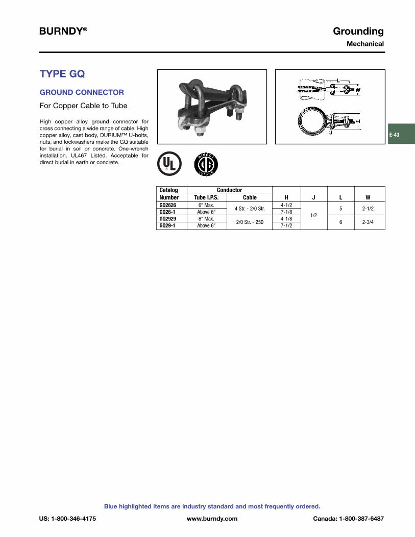
BURNDY® GroundingMechanical
US: 1-800-346-4175 www.burndy.com Canada: 1-800-387-6487
Blue highlighted items are industry standard and most frequently ordered.
E-43
TYPE GQ
GROUND CONNECTOR
For Copper Cable to Tube
High copper alloy ground connector forcross connecting a wide range of cable. High copper alloy, cast body, DURIUM™ U-bolts,nuts, and lockwashers make the GQ suitablefor burial in soil or concrete. One-wrenchinstallation. UL467 Listed. Acceptable fordirect burial in earth or concrete.
Catalog ConductorNumber Tube I.P.S. Cable H J L WGQ2626 6� Max. 4-1/2GQ26-1 Above 6�
4 Str. - 2/0 Str.7-1/8
5 2-1/2
GQ2929 6� Max. 4-1/81/2
GQ29-1 Above 6�2/0 Str. - 250
7-1/26 2-3/4

Grounding BURNDY®
Mechanical
Canada: 1-800-387-6487 www.burndy.com US: 1-800-346-4175
Blue highlighted items are industry standard and most frequently ordered.
E-44
TYPE GX
GROUND CONNECTOR
For Copper Cables
High copper alloy ground connector for crossconnecting a wide range of cable. The highcopper alloy cast body, DURIUM™ U-bolts,nuts, and lockwashers make the GX suitablefor burial in soil or concrete. One-wrenchinstallation. UL467 Listed. Acceptable fordirect burial in earth or concrete.
Catalog ConductorNumber Groove A Groove B H J L WGX4C4C 8 Sol. - 4 Str. 8 Sol. - 4 Str. 1-7/8 1-5/8 1-5/8GX264C 8 Sol. - 4 Str.GX2626
4 Sol. - 2/0 Str.4 Sol. - 2/0 Str.
2-1/2 1-3/4 1-3/4
GX294C 8 Sol. - 4 Str.GX2926 2/0 Sol. - 250 4 Sol. - 2/0 Str. 3/8 1-7/8GX2929 2/0 Sol. - 250GX344C 8 Sol. - 4 Str.
2-3/4 1-7/8
GX3426 4 Sol. - 2/0 Str. 2-1/8GX3429
300 - 5002/0 Sol. - 250
GX3434 300 - 500 4-1/4 1/2 2-5/8 2-5/8

BURNDY® GroundingMechanical
US: 1-800-346-4175 www.burndy.com Canada: 1-800-387-6487
Blue highlighted items are industry standard and most frequently ordered.
E-45
TYPE GRC
HIGH STRENGTH GROUND ROD CLAMP
For Copper Cable to Rod
High copper alloy ground connector for joining a range of cable to copper clad, gal vanized steel, and stainless steel groundrods. Slips over end of rod, one-wrench installation. UL467 Listed for direct burial inearth and concrete.
REA LISTED
Catalog Drive Conductor RangeNumber Rod Min. Max. H W L JGRC12 1/2 2 Str. 2.00 .89 .63GRC58 5/8
10 Sol.1 Str. 2.19 .95 .63 3/8
GRC34 3/4 8 Sol. 1/0 Str. 2.47 1.09 .65
TYPE GRL
LIGHT DUTYECONOMICAL GROUND RODCLAMP
UL467 Listed. Acceptable for direct burial.
Conductor RangeCatalog Number Rod Size Minimum Maximum
GRL3* 3/8 10 AWG 4 AWGGRL4 1/2 10 AWG 2 AWGGRL5 5/8 10 AWG 2 AWGGRL6 3/4 10 AWG 2 AWG
* GRL3 not UL Listed.
TYPE GCRT1/0GROUNDCONNECTORS
GROUND CLAMP RANGE TAKING, UP TO 1/0
The GCRT1/0 is a range taking ground rodclamp offering another choice from theBURNDY® family of connectors. TheGCRT1/0 works on 1/2�, 5/8� and 3/4� groundrods with a wire range of #8 through 1/0! Theclamp is UL467 Listed for direct burial in earthand concrete. Catalog number GCRT1/0.
Features and Benefits
• Range taking design helps reduce inventory.
• UL Listed and CSA Certified.• UL467 Listed for direct burial in earth and
concrete.
NEW!

Grounding BURNDY®
Mechanical
Canada: 1-800-387-6487 www.burndy.com US: 1-800-346-4175
Blue highlighted items are industry standard and most frequently ordered.
E-46
TYPE B
FLEXIBLE COPPER BRAID
Flexible copper braid jumpers designed totake up linear expansion and contraction,compensate for misalignment and absorbvibratory movement of electrical equipmentand devices.
Made of flat extra flexible, tinned, pure copper braid, with unplated, seamless, purecopper ferrules formed into a rectangularshape on each end.
Last two numbers in catalog number indicatetotal length of braid in inches (e.g., BD12N orBD12 is 12� long braid jumper).
Other lengths, plating and drilling areavailable. Refer to factory.
* This rating may vary with ambient conditions, orientationof the braid and other service conditions.
** Tongue drilled per (2) hole NEMA standard.
Number of ApproximateCatalog Braids in Ampere RatingNumber Ferrules C D E K L N T Indoor OutdoorBD12 † 2.50 1.25 .44 12BD12N** † 3.00 1.75 .56 12BD18 † 2.50 1.25 .44 18BD18N** †
1 .943.00 1.75 .56 18
.62 .13 190 225
BD24 † 2.50 1.25 .44 24BD24N** † 3.00 1.75 .56 24BE12 † 1.50 .44 12 .75BE12N** † 1.75 .56 12 .62BE18 † 1.50 .44 18 .75BE18N** †
1 1.50 3.001.75 .56 18 .62
.17 340 405
BE24 † 1.50 .44 24 .75BE24N** † 1.75 .56 24 .62BF12 † 1.50 .44 12 .75BF12N** † 1.75 .56 12 .62BF18 † 1.50 .44 18 .75BF18N** †
1 1.19 3.001.75 .56 18 .62
.25 360 430
BF24 † 1.50 .44 24 .75BF24N** † 1.75 .56 24 .62BG12 1.50 .44 12 .75BG12N** 1.75 .56 12 .62BG18 1.50 .44 18 .75BG18N**
1 1.50 3.001.75 .56 18 .62
.25 415 495
BG24 1.50 .44 24 .75BG24N** 1.75 .56 24 .62
Note: All sizes are listed to UL467 and specific sizes (†) arecertified to CSA C22.2, No. 41 Grounding and BondingEquipment Standards. Equivalent sizes may be designatedby suffix letters representing variations in length, mountingconfigurations, pad size and finish. Contact factory fordetails.

BURNDY® GroundingMechanical
US: 1-800-346-4175 www.burndy.com Canada: 1-800-387-6487
Blue highlighted items are industry standard and most frequently ordered.
E-47Number of ApproximateCatalog Braids in Ampere RatingNumber Ferrules C D E K L N T Indoor OutdoorB2D12 † 2.50 1.25 .44 12 .62B2D12N** †
.943.00 1.75 .56 12 .62
.25 380 455
B2E12 3.00 1.50 .44 12 .75B2E12N** 2
1.623.00 1.75 .56 12 .62
.25 530 635
B2F12 3.00 1.50 .44 12 .75B2F12N**
1.383.00 1.75 .56 12 .62
.38 600 720
B2G12N** 1.50 3.00 1.75 .56 12 .62 .50 700 840B3D12 † 2.50 1.25 .44 12 .62B3D12N** †
1.193.00 1.75 .56 12 .62
.25 470 560
B3E12 3.00 1.50 .44 12 .75B3E12N**
1.643.00 1.75 .56 12 .62
.31 700 840
B3F123
3.00 1.50 .44 12 .75B3F12N**
1.443.00 1.75 .56 12 .62
.56 820 980
B3G12 3.00 1.50 .44 12 .75B3G12N**
1.693.00 1.75 .56 12 .62
.69 960 1150
B4D12 2.50 1.25 .44 12 .62B4D12N**
1.193.00 1.75 .56 12 .62
.32 600 720
B4E12 3.00 1.50 .44 12 .75B4E12N** 4
1.643.00 1.75 .56 12 .62
.36 850 1020
B4F12 3.00 1.50 .44 12 .75B4F12N**
1.503.00 1.75 .56 12 .62
.78 1000 1200
B4G12N** 1.69 3.00 1.75 .56 12 .62 .94 1200 1440
TYPE B
FLEXIBLE COPPER BRAID(Continued)
* This rating may vary with ambient conditions, orientationof the braid and other service conditions.
** Tongue drilled per (2) hole NEMA standard.
Note: All sizes are listed to UL467 and specific sizes (†) arecertified to CSA C22.2, No. 41 Grounding and BondingEquipment Standards. Equivalent sizes may be designatedby suffix letters representing variations in length, mountingconfigurations, pad size and finish. Contact factory fordetails.

Grounding BURNDY®
Mechanical
Canada: 1-800-387-6487 www.burndy.com US: 1-800-346-4175
Blue highlighted items are industry standard and most frequently ordered.
E-48
TYPES GB, GBM
GROUND CONNECTOR
For Copper Cable to Bar
High copper alloy ground connector for joining a range of cable to 1/4� thick bar.*Type GB separates cable from bar, GBMclamps cable directly on bar surface. One-wrench installation. UL467 Listed. Thehigh copper alloy cast body and DURIUM™bolts, nuts, and lockwashers make the GBand GBM suitable for direct burial in con-crete or ground.
TYPES GC, GCM
GROUND CONNECTOR
For Two Copper Cables to Bar
High copper alloy ground connector for joining a wide range of two parallel cables to1/4� thick bar.* Type GC separates cable frombar, GCM clamps cable to bar surface. One-wrench installation. UL467 Listed. Thehigh copper alloy cast body and DURIUM™bolts, nuts, and lockwashers make the GCand GCM suitable for direct burial in concrete or ground.
+ GBL30 is not UL listed.Add “GS” suffix for galvanized steel hardware.* For other bar thicknesses see note at bottom of page E-48.
Smooth oval-shank bolts are available upon request for cable-tray applications (example: GC30G3). Also refer to type GC-CT. Add “GS” suffix for galavanized steel hardware.* For other bar thicknesses see note at bottom of page E-48.
Type GC
Type GCM
Type GB
Type GBMType
GBMType GB
Type GC
Type GCM
H H W WCatalog Number Type Type Type Type
Type GB Type GBM Conductor GB/GBL GBM J GB/GBL GBMGB4C GBM4C 8 Sol. - 4 Str. 1-1/2 1-1/4 1-1/4GB26 GBM26 4 Sol. - 2/0 Str.
1-1/2 3/81-1/2 1-1/2
+GBL30 4 Sol. - 300 2 7/8 0GB29 GBM29 2/0 Sol. - 250 2 1/2 2 2GB34 GBM34 300 - 500 3 2-1/4 2-3/8 2-3/8
H H W WCatalog Number Type Type Type Type
Type GC Type GCM Conductor GC/GCL GCM J GC/GCL GCMGC4C4C GCM4C 8 Sol. - 4 Str. 1-1/2 1-3/8 1GC2626 GCM26 4 Sol. - 2/0 Str. 2
1-1/2 3/81-3/4 1-3/8
GCL30 GCM30 4 Str. - 300 2 — — 1 —GC2929 GCM29 2/0 Sol. - 250 2-1/4 2 — 2-1/4 2GC3434 GCM34 300 - 500 2-7/8 2-1/4 1/2 2-7/8 2-5/8

BURNDY® GroundingMechanical
US: 1-800-346-4175 www.burndy.com Canada: 1-800-387-6487
Blue highlighted items are industry standard and most frequently ordered.
E-49
TYPE GL
GROUND CONNECTOR
For Two Copper Cables to Bar
High copper alloy ground connector for join-ing a wide range of two parallel cables to 1/4�
thick bar.* Two-bolt design, separates cablefrom bar. One-wrench installation. UL467Listed. The high copper alloy cast body andDURIUM™ bolts, nuts, and lockwashersmake them suitable for direct burial in concrete or ground.
TYPE GZ
GROUND CONNECTOR
For Copper Cable to Bar
High copper alloy ground connector for joining a wide range of cable to 1/4� thickbar*. Cable is gripped by curving it aroundthe clamping bolt in connector groove.UL467 Listed. The high copper alloy castbody and DURIUM™ bolts, nuts, and lock-washers make them suitable for direct burialin concrete or ground.
* For other bar thicknesses see note at bottom of page.
NOTE:* The GB, GBM, GC, GCM, GL and GZ are all
used for joining a range of cable to bar. The catalog numbers in each table accommodatethe indicated cable range and up to 1/4� thickbar. Optional bolt lengths are available toaccommodate up to 1� thick bar. For bar thick-nesses from 1/4� to 1/2�, add the suffix “T4” tothe catalog number in the table. For bar thick-nesses from 1/2� to 1�, add the suffix “T8” to thecatalog number in the table.
CatalogNumber* Conductor H J WGL4C4C 8 Sol. - 4 Str. 1-1/2 1-3/8GL2626 4 Sol. - 2/0 Str. 2
3/81-3/4
GL2929 2/0 Sol. - 250 2-1/4 2-1/4GL3434 300 - 500 2-7/8
1/22-7/8
CatalogNumber* Conductor H J WGZ4C-38 1-1/2 3/8 1-1/8GZ4C-12 8 Str. - 4 Str. 1-7/8 1/2GZ4C-58 5/8
1-3/4
GZ26-382
3/8 1-5/8GZ26-12 3 Str. - 2/0 Str. 2-1/8 1/2GZ26-58 5/8
1-3/4
GZ29-382-1/4
3/8GZ29-12 3/0 Str. - 250 2-3/8 1/2 2-1/4GZ29-58 2-1/2 5/8

Grounding BURNDY®
Mechanical
Canada: 1-800-387-6487 www.burndy.com US: 1-800-346-4175
Blue highlighted items are industry standard and most frequently ordered.
E-50
TYPE GC-CT
CABLETRAY GROUND CLAMP
This unique connector incorporates featureswhich are unmatched. Made of tin-platedcast copper alloy, it accommodates eitherone or two conductors, copper or aluminumcable. In addition to a low profile head with adeep Phillips recess, the galvanized steelbolt has a ribbed neck which prevents rota-tion during installation when installed in a .44diameter hole. When used on aluminum con-ductor, the cable must be scratch brushedand PENETROX™ A joint compound mustbe used on cable and connector.
UL467 Listed for copper conductor only.Suitable for direct burial in concrete or earth.
NOTE:The bolt head is mounted on the inside wall of cabletray toavoid damage to the cable insulation.May be used with aluminum or galvanized steel cable tray.
Accommodates Copper orCatalog Alunimum ConductorNumber in Either Groove B CF H J W
#6 Sol. (.162 Dia.) - GC2525CT
1/0 Str. (.372 Dia.)1.12 .56 1.95 3/8” - 16 1.45
#2 Sol. (.258 Dia.) - GC2626CT
2/0 Str. (.419 Dia.)1.12 .56 1.95 3/8” - 16 1.70
2/0 Str. (.414 Dia.) - GC2929CT
250 kcmil (.575 Dia.)1.12 .56 2.20 3/8” - 16 1.98

BURNDY® GroundingMechanical
US: 1-800-346-4175 www.burndy.com Canada: 1-800-387-6487
Blue highlighted items are industry standard and most frequently ordered.
E-51
TYPE GTC1AC34RA
PROTECTIVE GROUNDINGCLAMP
For Pad Mounted Equipment
A newly designed Protective GroundingClamp for making secure connections wheninstalling Protective Grounding Sets on PadMounted Equipment.
Features a 90° right angle side entry for fer-rule. Cable connection will now exit clampparralel with grounding bar allowing cable setto remain within the cabinet. Closing the cabi-net doors will now be easier and will notrequire infringing on the safety clearance zone.
Eliminates awkward hotstick mounting andtightening of clamp jaws from elevatedangles. Improves safety thanks to easierrespect of minimum approach distance.
The clamp is used as a base for new ground-ing sets or can be retrofit on most groundingsets for pad mounted equipment.
Designed and manufactured in the U.S.A.
Catalog Number: GTC1AC34RA
Features
• ASTM classification (F855-04):– Grade 3 (27kA for 15 cycles)– Class A/Type I/C-shape– Brass alloy– Weight: 1.85 Lbs.
• Jaw range: round section conductor 3/8�
to 3/4� diameter.
3.63[92]
5.15[131]
5.14[128]
.32[8]
1.75[44]
Conductor groove will accept a decimal range of 3/8� to 3/4�
.645 diameter plain hole to receive standard 5/8 - 11 UNC threaded ferrules
Single phase configuration(using standard hardware)Triple phase configuration(using a 4-way connector)
Possible base for a Grounding Set:

Grounding BURNDY®
Mechanical
Canada: 1-800-387-6487 www.burndy.com US: 1-800-346-4175
Blue highlighted items are industry standard and most frequently ordered.
E-52
TYPE GIE-G
GROUND CONNECTOR
For Vehicle Grounding Heavy Duty Construction
High-strength copper alloy ground clampsfor grounding gasoline trucks, tank cars, air-craft and other vehicles where danger ofexplosion due to static electricity exists.Corrosion resistant and supplied with non-sparking, adjustable, replaceable contactgrip screws. Automatic safety release dis-connects should a vehicle unexpectedlymove from the grounded area.Accommodates 4 Str. flexible copper cable.
1.2�
MAX.OPENING
TYPE GIE-G
GROUND CONNECTOR
Accommodates flexible rubber sheath cableranging from #6 to #2 conductor.
Catalog Number: GIE2CG3
8 1⁄8�
Replaceable Contact Grip ScrewsCatalog Number Catalog Number Material Point Configuration
GIE4CG3P5 Cone PointGIE4CG3
GIE4CG3P7Beryllium Copper
Cup PointGIE4CG4P5 Cone Point
GIE4CG4GIE4CG4P7
Stainless SteelCup Point

BURNDY® GroundingMechanical
US: 1-800-346-4175 www.burndy.com Canada: 1-800-387-6487
Blue highlighted items are industry standard and most frequently ordered.
E-53
RAIL CONNECTORMechanical clamp connectors designed foruse in power, contact or running rail appli -cations. Connectors are cast of a high conductivity copper alloy, tin-plated, and assembled with high-strength DURIUM™hardware. Connectors designed for extend-ed service life.
* Tin-plated.
Fig. 1 Fig. 2
Fig. 3 Fig. 4
Catalog Fig.Number No. Accommodates B H HH L W
J278 1 100 Lbs. A.R.E.A. Running Rail 1.81 1.88 1.72 7.50 .88J279 1 75 or 90 Lbs. Running Rail 1.81 1.71 1.55 7.50 .88J280 1 150 Lbs. Contact Rail 2.12 2.08 1.92 7.00 1.25J295 2 150 Lbs. Third Rail 2.62 3.50 3.50 7.75 3.00
150 Lbs. NMC Contact Rail and RGC44G1* 3
(1) 800-1000 kcmil CU Cable1.75 2.82 2.25 10.00 1.75
115 Lbs. Contact or Running Rail and RGC39G1* 4
(1) 500-750 kcmil CU Cable2.75 2.00 4.78 8.32 1.25

Grounding BURNDY®
Mechanical
Canada: 1-800-387-6487 www.burndy.com US: 1-800-346-4175
Blue highlighted items are industry standard and most frequently ordered.
E-54
TYPE QGFL
BARTAP™
For Copper Cable to Flat Bar or Pad
High copper alloy BARTAP™ for joining arange of cable to bar or pad. One-wrenchinstal lation. DURIUM™ nut and lockwasher.
TYPE GA-H
GROUND CONNECTOR
For Copper Cable to “H” Beam
High copper alloy ground connector for join-ing a wide range of cable parallel to “H”beams or square tube. Hardware is made from DURIUM™ for superior corrosionprotection.
* Can be installed side by side or in line on NEMA drilled bar.
Catalog TNumber Conductor B H J (Max.) WQGFL1CB1 1-7/8 1/4QGFL1CB1T6
10 Sol. - 1 Str. 1-1/82-3/8 3/4
1
QGFL26B1 2-1/83/8
1/4QGFL26B1T6 1-1/4 2-5/8 3/4QGFL26B2*
8 Sol. - 2/0 Str.1-1/2 1/4
1-1/8
QGFL26B2T6* 1-1/2 2-7/8 3/4QGFL29B1* 2-5/8 1/4QGFL29B1T6*
6 Str. - 250 1-5/83-1/8 3/4
1-3/8
QGFL31B1* 2-7/8 1/4QGFL31B1T6*
2 Sol. - 350 1-3/43-1/4 3/4
1-5/8
QGFL34B1 3-1/8 1/4QGFL34B1T6
1/0 Sol. - 500 23-5/8 3/4
1-3/4
QGFL39B1 3-1/41/2
1/4QGFL39B1T6
350 - 7503-5/8 3/4
1-3/4
QGFL44B1 3-3/8 1/4QGFL44B1T6
750 - 10004-1/8 3/4
2-1/8
QGFL46B12-1/4
4 1/4QGFL46B1T6
1000 - 15004-1/2 3/4
2-1/2
QGFL48B1 1500 - 2000 4-3/4 1/4 3
Catalog ConductorNumber “H” Beam Cable H J WGA25H26 1-7/8� � 1-7/8� - 2-1/2� � 2-1/2� 4 Sol. - 2/0 Str. 4-3/4 3/8 4

BURNDY® GroundingMechanical
US: 1-800-346-4175 www.burndy.com Canada: 1-800-387-6487
Blue highlighted items are industry standard and most frequently ordered.
E-55
TYPE GRF
UNIGROUND™ RAISEDFLOOR GROUNDING CONNECTOR
The BURNDY® UNIGROUND™ is a universalgrounding clamp, specifically designed for allraised flooring systems. It can be installed onround or square pedestals and can accommodate one or two grounding wires tomake an efficient grid. The underfloor signalreference grid provides the low impedanceground path that attenuates high frequencystatic and 60 Hz transient noise for cleanerdata output. UL467 Listed.
Features and Benefits
• One connector fits all applications.�Ease of specification and installation.
• Single bolt design.�Ease of installation:
— No need to disassemble.— Single wrench installation.
• Accepts 1 or 2 ground conductors.�Requires less connectors to install
signal reference grid.• Tin plated cast bronze construction.
�Resists corrosion and provides extend-ed life ground connection.
• Grounds all pedestals (round or square).Will handle up to 7/8� square and 1� round.�Ease of installation. One connector
does it all• Serves 3 needs:
1. Signal Reference Grid.2. Static Ground.3. Fault Current Ground.
�UNIGROUND™ solves all possiblegrounding problems found in computerapplications today.
Catalog Number of Conductor Pedestal TypeNumber Conductors Size Sol. & Str. Round Square B H J WGRF4C-3 1 or 2 #8 - #2 Up to 1� Up to 7/8� 1.96 3.14 3/8� 1.76GRF4C-4 1 or 2 #8 - #2 Up to 3/4� Up to 5/8� 1.79 3.13 3/8� 1.40

Grounding BURNDY®
Mechanical
Canada: 1-800-387-6487 www.burndy.com US: 1-800-346-4175
Blue highlighted items are industry standard and most frequently ordered.
E-56
TYPES GP-G1, GP-RT
RAISED FLOOR GROUNDING CLAMPS
High copper alloy ground connector forraised floor computer grounding applica-tions. These connectors can be installed onround and square pedestal applications andwill accommodate one or two groundingwires to make an efficient grid. The under-floor signal reference grid provides the lowimpedance ground path that attenuates highfrequency static and 60 Hz transient noise forcleaner data output. UL467 Listed.
In addition we offer the GP1726RT, which isespecially designed for penetrating epoxypaint on pedestals. This patented connectoroffers a low impedance, time saving connec-tion between conductors and the Pedestal.
Features and Benefits
• Accepts 1 or 2 Ground Conductors�Requires less connectors to install sig-
nal reference grid.• Made of copper alloy.• DURIUM™ U-Bolts, nuts and lockwashers.
�Provides a low impedance ground pathfor maximum performance.
• Grounds all pedestals (round or square).• Will handle from 3⁄4� to 1� round or square.
�Ease of installation.• Serves 3 needs.
1. Signal Reference Grid.2. Static Ground.3. Fault Current Ground.
�Connectors solves all possible grounding problems found in computerapplications today.
GP1726RT
Catalog Number of Conductor Pedestal TypeNumber Conductors Size Sol. & Str. Round or Square B J L WGP654CG1 1 or 2 #8 Sol. - 4 Str. 3/4� - 1� Round 1.5 3/8� 1.31 2.38GP64526G1 1 or 2 #4 Sol. - 2/0 Str. 3/4� - 7/8� Square 1.5 3/8� 1.69 2.38GP1526G1 1 or 2 #4 Sol. - 2/0 Str. 1-1/4� Round 1.75 3/8� 1.69 2.62GP1726RT 1 or 2 #6 Sol. - 2/0 Str. 2� Round 2.12 3/8� 1.50 3.22GP1726G1 1 or 2 #6 Sol. - 2/0 Str. 2� Round 2.12 3/8� 1.50 3.22

BURNDY® GroundingMechanical
US: 1-800-346-4175 www.burndy.com Canada: 1-800-387-6487
Blue highlighted items are industry standard and most frequently ordered.
E-57
TYPE BBB
BURNDY® BusBar
Copper BusBar
Bare copper BusBar, UL Listed for grounding.Available in many sizes and hole patterns.Brackets and insulators included with moststyles. Also available in undrilled, horizontaland vertical versions.
BusBar is used in a variety of applications.Can be used as a common ground point and“power” applications as well.
3.75[95]
“T”.25[6]
“T”.25[6]
3.75[95]
Catalog Fig. Insulator & T - Bar W - Bar L - Bar No. ofNumber No. Bracket Thickness Width Length E1 E2 E3 F1 F2 Holes KBBB14210A 1 A 1/4� 2� 10� .63 — — 1.00 — 16 .28BBB14224B 2 A 1/4� 2� 24� .625 .75 — 1.00 1.00 36 .28
6 6-32BBB14410C 3 A 1/4� 4� 10� .75 1.00 — 1.25 —
16 .286 6-32
BBB14410D 4 A 1/4� 4� 10� 1.25 1.00 — 1.13 1.1316 .28
BBB14412E 5 A 1/4� 4� 12� .75 — — 2.00 1.25 18 .4412 .44
BBB14412F 6 A 1/4� 4� 12� 1.00 .75 — 2.00 1.2512 .28
BBB14416G 7 B 1/4� 4� 16� .75 1.00 — 1.69 — 24 .4416 .44
BBB14416H 8 B 1/4� 4� 16� 1.00 1.00 .75 1.69 —16 .2534 .44
BBB14420J 9 B 1/4� 4� 20� 1.00 1.00 .75 1.00 —34 .25
BBB412UD N/A A 1/4� 4� 12� N/A N/A N/A N/A N/A N/A N/ABBB424UD N/A B 1/4� 4� 24� N/A N/A N/A N/A N/A N/A N/ABBBHR19* N/A N/A 3/16� 3/4� 19� .38BBBVR36* N/A N/A 1/4� 5/8� 36� .32
Contact Factory for Dimensions
* Not UL Listed.
Bracket/Insulator A Bracket/Insulator B
“W”2.00[51]
Ø.44[11]
“E1”.63[16]
4.00[102]
“F”1.00[25]
(7 Plcs)
“K”Ø.28[7]
(16 Plcs)
8.50[216]
“L”10.00[254]
“W”2.00[51]
“E2”.75[19]
“K”Ø.28[7]
(36 Plcs)
“E1”.625[15.9]
Ø.44[11]
4.00[102]
“L”24.00[610]
22.00[559]
“F1”1.00[25]
(8 Plcs)
“F2”1.00[25]
(8 Plcs)
Figure 1 Figure 2
(Figures continued on next page)

Grounding BURNDY®
Mechanical
Canada: 1-800-387-6487 www.burndy.com US: 1-800-346-4175
Blue highlighted items are industry standard and most frequently ordered.
E-58
TYPE BBB
BURNDY® BusBar
Copper BusBar (Continued)
Ø.44[11]
9.00[229]
6 - 32 Tapped Holes(6 Plcs)“F”
1.25[32] (5 Plcs)
“L”10.00[254]
“K2”Ø.28 [7] (16 Plcs)
“W”4.00[102]
“E2”1.00[25]
“E1”.75[19]
Figure 3
“K1”6 - 32 Tapped Holes
(6 Plcs)
“F1”1.13[29]
(5 Plcs)
“E1”1.25[32]
“W”4.00[102]
“E2”1.00[25]
Ø.44[11]“L”
10.00[254]
“F2”1.13[29]
(5 Plcs)
“K2”Ø.28[7]
(16 Plcs)8.50[216]
Figure 4
“L”12.00[305]
11.25[286]
Ø.44[11]
“K”Ø.44[11]
(18 Plcs)
“F2”1.25[32]
(2 Plcs)
“F1”2.00[51]
(3 Plcs)
“E1”.75[19]
“E2”1.00[25]
Figure 5
“K1”Ø.44[11]
(12 Plcs)
“F1”2.00[51]
(3 Plcs)“E1”1.00[25] 1.00
[25]
“E2”.75[19]
“L”12.00[305]
“F2”1.25[32]
(2 Plcs)
“K2”Ø.25[7]
(12 Plcs)
Figure 6
“K”Ø.44[11]
(24 Plcs)
“L”16.00[406]
“F”1.69[43]
(7 Plcs)
“E2”1.00[25]
“E1”.75[19]
Figure 7
“L”16.00[406]
“K2”Ø.13[3]
(16 Plcs)
“K1”Ø.44[11]
(16 Plcs)
“F”1.69[43]
(7 Plcs)“E1”1.00[25]
“E2”1.00[25]“E3”
.75[19]
Figure 8
“L”20.00[508]
“K”Ø.44[11]
(34 Plcs)
“K2”Ø.25[6]
(34 Plcs)
“E3”.75[19]
“E2”1.00[25]
“E1”1.00[25]
“F”1.00[25]
(16 Plcs)
Figure 9

BURNDY® GroundingBURNDYWeld® Exothermic
US: 1-800-346-4175 www.burndy.com Canada: 1-800-387-6487
Blue highlighted items are industry standard and most frequently ordered.
E-59
TABLE OF CONTENTSBURNDYWeld®
BURNDYWeld®
Introduction. . . . . . . . . . . . . . . . E-60
Making a BURNDYWeld®
Connection . . . . . . . . . . . . . E-61
WELD METAL . . . . . . . . . . . . . E-62
Type BCC-1 . . . . . . . . . . . . . . . E-63
Type BCC-2 . . . . . . . . . . . . . . . E-64
Type BCC-4 . . . . . . . . . . . . . . . E-65
Type BCC-11 . . . . . . . . . . . . . . E-66
Type BCC-6 . . . . . . . . . . . . . . . E-67
Type BCC-14 . . . . . . . . . . . . . . E-67
Type BCC-7 . . . . . . . . . . . . . . . E-68
Type BCR-1 . . . . . . . . . . . . . . . E-69RUS Accepted
Type BCR-2 . . . . . . . . . . . . . . E-70
Type BCR-3 . . . . . . . . . . . . . . E-71
Type BCR-17 . . . . . . . . . . . . . . E-72
Type BCR-24 . . . . . . . . . . . . . . E-73
Single Shot Molds . . . . . . . . . E-74
Type BCS-1 . . . . . . . . . . . . . . . E-75
Type BCS-8 . . . . . . . . . . . . . . . E-75
Type BCS-2 . . . . . . . . . . . . . . . E-76
Type BCS-9 . . . . . . . . . . . . . . . E-76
Type BCS-3 . . . . . . . . . . . . . . . E-77
Type BCS-23 . . . . . . . . . . . . . . E-78
Type BCS-4 . . . . . . . . . . . . . . . E-79
Type BCS-6 . . . . . . . . . . . . . . . E-79
Type BCS-7. . . . . . . . . . . . . . . . E-80
Type BCS-18 . . . . . . . . . . . . . . E-80
BURNDY®
GROUNDMAX™ . . . . E-87 - E-88
BURNDY® GRIDMAX™ . . . . . . E-89
For mold types or BURNDYWeld® items not shown, please contact factory.

Grounding BURNDY®
BURNDYWeld® Exothermic
Canada: 1-800-387-6487 www.burndy.com US: 1-800-346-4175
Blue highlighted items are industry standard and most frequently ordered.
E-60
BURNDYWeld®
The BURNDYWeld® connection process is asimple, efficient method of welding copper tocopper or copper to steel. One advantage isthat NO outside power is required whenusing the BURNDYWeld® exothermicprocess. The BURNDYWeld® process useshigh temperature reaction of powdered cop-per oxide and aluminum. The reaction takesplace in a semi-permanent graphite mold.These molds will last for fifty or more welds ifproper care is given. The reaction takesplace very rapidly, therefore the total amountof heat applied to the conductors or surfacesis considerably less than that of brazing orsoldering. It is important to remember thiswhen welding to insulated cable or thin wallpipe.
This system is very field friendly, since it islight and portable and requires no outsidepower source. It requires very little time orskill to obtain an efficient, maintenance freeconnection when using the BURNDYWeld®
process.
For more information visit our website atwww.burndy.com.
The BURNDYWeld® process has been usedto weld materials other than copper for elec-trical purposes. Materials welded include:
Stainless Steel Columbium BrassCopperweld® Plain Steel BronzeNichrome V Everdur® NiobiumGalvanized Steel Kama ChromaxSilcone Bronze Steel Rail Cast IronCopper Clad Steel Cor-Ten® Monel
When welding to galvanized steel it is recom-mended to resurface exposed bare steel.
The BURNDYWeld® connection is a molecu-lar weld. The weld metal has the same melting point as copper. These factors alongwith the increased cross section of the connection, BURNDYWeld® connections:
1. Will not be affected by a high currentsurge. Tests have shown that the electri-cal conductor will melt before theBURNDYWeld® connection when sub-jected to high short circuit current.Consult IEEE Standard 837-1989.
2. Will not loosen or corrode at the point ofweld. There are no contact surfaces ormechanical pressures involved. ABURNDYWeld® connection becomes anintegral part of the conductor.
3. Have a current-carrying capacity equal toor greater than that of the conductors.
Lid
Graphite Mold
Weld Cavity
Ground Rod
Cable
Tap Hole
Weld Metal
Starting Powder
For mold types or BURNDYWeld® items not shown, please contact factory.
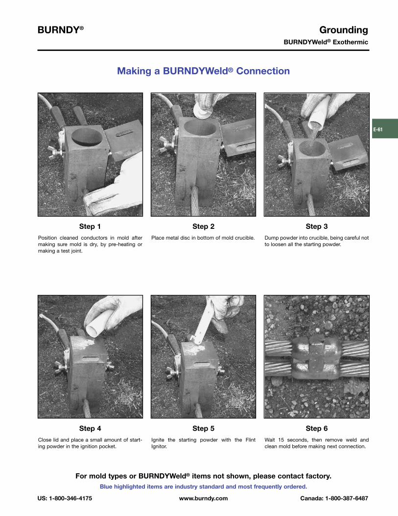
BURNDY® GroundingBURNDYWeld® Exothermic
US: 1-800-346-4175 www.burndy.com Canada: 1-800-387-6487
Blue highlighted items are industry standard and most frequently ordered.
E-61
Making a BURNDYWeld® Connection
Step 1
Position cleaned conductors in mold aftermaking sure mold is dry, by pre-heating ormaking a test joint.
Step 2
Place metal disc in bottom of mold crucible.
Step 3
Dump powder into crucible, being careful notto loosen all the starting powder.
Step 4
Close lid and place a small amount of start-ing powder in the ignition pocket.
Step 6
Wait 15 seconds, then remove weld andclean mold before making next connection.
Step 5
Ignite the starting powder with the FlintIgnitor.
For mold types or BURNDYWeld® items not shown, please contact factory.
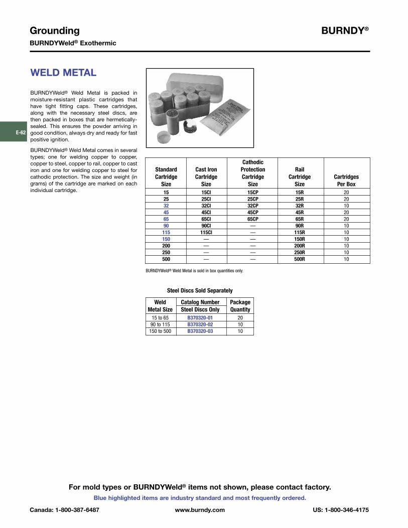
Grounding BURNDY®
BURNDYWeld® Exothermic
Canada: 1-800-387-6487 www.burndy.com US: 1-800-346-4175
Blue highlighted items are industry standard and most frequently ordered.
E-62
For mold types or BURNDYWeld® items not shown, please contact factory.
WELD METAL
BURNDYWeld® Weld Metal is packed inmoisture-resistant plastic cartridges thathave tight fitting caps. These cartridges,along with the necessary steel discs, arethen packed in boxes that are hermetically-sealed. This ensures the powder arriving ingood condition, always dry and ready for fastpositive ignition.
BURNDYWeld® Weld Metal comes in severaltypes; one for welding copper to copper,copper to steel, copper to rail, copper to castiron and one for welding copper to steel forcathodic protection. The size and weight (ingrams) of the cartridge are marked on eachindividual cartridge.
CathodicStandard Cast Iron Protection RailCartridge Cartridge Cartridge Cartridge Cartridges
Size Size Size Size Per Box15 15Cl 15CP 15R 2025 25Cl 25CP 25R 2032 32Cl 32CP 32R 1045 45Cl 45CP 45R 2065 65Cl 65CP 65R 2090 90Cl — 90R 10
115 115Cl — 115R 10150 — — 150R 10200 — — 200R 10250 — — 250R 10500 — — 500R 10
BURNDYWeld® Weld Metal is sold in box quantities only.
Weld Catalog Number PackageMetal Size Steel Discs Only Quantity
15 to 65 B370320-01 2090 to 115 B370320-02 10150 to 500 B370320-03 10
Steel Discs Sold Separately

BURNDY® GroundingBURNDYWeld® Exothermic
US: 1-800-346-4175 www.burndy.com Canada: 1-800-387-6487
Blue highlighted items are industry standard and most frequently ordered.
E-63
BCC-1 TYPE MOLDS
Horizontal End to End
BCC-1 Type Molds are used for horizontalend to end cable connections.
Size range is #6 through 1000 kcmil solid orconcentric stranded copper conductors.
Contact BURNDY® for information on moldsfor conductors not listed below.
Price Weld HandleCable Mold Number Key Metal Clamps
#8 Use Type BCC-14 on Page E-67 — — —#6 Use Type BCC-14 on Page E-67 — — —#4 B-5623 18 † * 25 N/A#3 B-5624 18 † * 32 N/A#2 B-5625 18 † * 32 N/A#1 B-5626 18 † * 32 N/A1/0 B-205 4 45 B-1062/0 B-206 4 65 B-1063/0 B-207 4 90 B-1064/0 B-208 4 90 B-106
250 kcmil B-209 4 115 B-106300 kcmil B-210 4 115 B-106350 kcmil B-211 4 150 B106500 kcmil B-213 4 200 B-107750 kcmil B-214 5 2-150 B-1071000 kcmil B-215 5 2-200 B-107
• For sizes not listed, contact BURNDY®.• Molds listed are for concentric stranded cable. Add suffix
“-S” to mold number for solid conductors.• For heavy duty molds, molds with wear plates or molds
for Copperweld® cable, contact BURNDY®.• For expedited service, contact BURNDY®.
Required Tools:Handle Clamps (see chart for correct handles)† Sold complete with handles* B38-0309-00 Flint Ignitor (included)
Other recommended accessories:B38-3922-00 Mold Cleaning Brush (pg E-92)B38-0135-00 Cable Cleaning Brush (pg E-92)B38-0330-00 Cable Clamp (pg E-92)
For mold types or BURNDYWeld® items not shown, please contact factory.

Grounding BURNDY®
BURNDYWeld® Exothermic
Canada: 1-800-387-6487 www.burndy.com US: 1-800-346-4175
Blue highlighted items are industry standard and most frequently ordered.
E-64
For mold types or BURNDYWeld® items not shown, please contact factory.
TYPE BCC-2 MOLDS
Horizontal Cable Tap toHorizontal Cable Run
Type BCC-2 Molds are used to join horizon-tal cable tap to a horizontal run cable.
Size range is #6 through 750 kcmil solid orconcentric stranded copper conductors.
Contact BURNDY® for information on moldsfor conductors not listed below.
Cable Price Weld HandleRun Tap Mold Number Key Metal Clamps#6 #6 Use Type BCC-14 on Page E-67 — — —#4 #4 B-221 4 32 B-106
#2 B-223 4 45 B-106#2
#4 B-224 4 45 B-106#1 B-225 4 45 B-106
#1 #2 B-226 4 45 B-106#4 B-227 4 45 B-1061/0 B-228 4 90 B-106#1 B-229 4 45 B-106
1/0#2 B-230 4 45 B-106#4 B-231 4 45 B-1062/0 B-232 4 90 B-1061/0 B-233 4 90 B-106
2/0 #1 B-234 4 45 B-106#2 B-235 4 45 B-106#4 B-5475 4 45 B-1063/0 B-236 4 115 B-1062/0 B-237 4 90 B-1061/0 B-238 4 90 B-106
3/0#1 B-239 4 45 B-106#2 B-240 4 45 B-106#4 B-5574 4 45 B-1064/0 B-241 4 150 B-1063/0 B-242 4 115 B-1062/0 B-243 4 90 B-106
4/0 1/0 B-244 4 90 B-106#1 B-245 4 90 B-106#2 B-246 4 90 B-106#4 B-5021 4 90 B-106
250 kcmil B-247 4 150 B-1064/0 B-248 4 150 B-1063/0 B-249 4 150 B-106
250 kcmil 2/0 B-250 4 90 B-1061/0 B-251 4 90 B-106#1 B-252 4 90 B-106#2 B-253 4 90 B-106
Cable Price Weld HandleRun Tap Mold Number Key Metal Clamps
300 kcmil B-254 4 200 B-106250 kcmil B-255 4 150 B-106
4/0 B-256 4 150 B-1063/0 B-257 4 150 B-106
300 kcmil2/0 B-258 4 90 B-1061/0 B-259 4 90 B-106#1 B-260 4 90 B-106#2 B-261 4 90 B-106
350 kcmil B-262 4 200 B-106300 kcmil B-263 4 200 B-106250 kcmil B-264 4 200 B-106
4/0 B-265 4 150 B-106350 kcmil 3/0 B-266 4 150 B-106
2/0 B-267 4 90 B-1061/0 B-268 4 90 B106#1 B-269 4 90 B-106#2 B-270 4 90 B-106
500 kcmil B-280 4 2-150 B-106350 kcmil B-282 4 200 B-106300 kcmil B-283 4 200 B-106250 kcmil B-284 4 200 B-106
500 kcmil 4/0 B-285 4 150 B-1062/0 B-286 4 90 B-1061/0 B-287 4 90 B-106#1 B-288 4 90 B-106#2 B-289 4 90 B-106
750 kcmil B-290 5 500 B-107500 kcmil B-291 5 2-200 B-107350 kcmil B-293 4 250 B-106300 kcmil B-294 4 200 B-106
750 kcmil250 kcmil B-295 4 200 B-106
4/0 B-296 4 150 B-1062/0 B-297 4 150 B-1061/0 B-298 4 150 B-106
• For sizes not listed, contact BURNDY®.• Molds listed are for concentric stranded cable. Add suffix “-S” to mold number for solid
conductors.• For heavy duty molds, molds with wear plates or molds for Copperweld® cable, contact
BURNDY®.• For expedited service, contact BURNDY®.
Required Tools: Handle Clamps (see chart for correct handles)B38-0309-00 Flint Ignitor
Other recommended accessories:B40-0319-01 Mold Cleaner for cartridge sizes #15-#65 (pg E-92)B40-0319-03 Mold Cleaner for cartridge sizes #90-#500 (pg E-92)B38-3922-00 Mold Cleaning Brush (pg E-92)B38-0135-00 Cable Cleaning Brush (pg E-92)B38-0330-00 Cable Clamp (pg E-92)

BURNDY® GroundingBURNDYWeld® Exothermic
US: 1-800-346-4175 www.burndy.com Canada: 1-800-387-6487
Blue highlighted items are industry standard and most frequently ordered.
E-65
For mold types or BURNDYWeld® items not shown, please contact factory.
TYPE BCC-4 MOLDS
Horizontal to Horizontal Cable Cross
Type BCC-4 Molds are used to join two hor-izontal cables at right angles. One cable iscut and the other is a through run.
Size range is #6 through 500 kcmil solid orconcentric stranded copper conductors.
Contact BURNDY® for information on moldsfor conductors not listed below.
Cable Price Weld HandleRun Tap Mold Number Key Metal Clamps#6 #6 Use Type BCC-11 on Page E-66#4 #4 B-423 4 45 B-106#3 #3 B-424 4 45 B-106
#2 B-425 4 65 B-106#2
#4 B-426 4 65 B-106#1 B-427 4 65 B-106
#1 #2 B-428 4 65 B-106#4 B-429 4 65 B-1061/0 B-430 4 90 B-106#1 B-431 4 90 B-106
1/0#2 B-432 4 90 B-106#4 B-433 4 90 B-1062/0 B-434 4 115 B-1061/0 B-435 4 115 B-106
2/0#1 B-436 4 115 B-106#2 B-437 4 115 B-1063/0 B-438 4 150 B-1062/0 B-439 4 150 B-106
3/0 1/0 B-440 4 115 B-106#1 B-441 4 115 B-106#2 B-442 4 115 B-1064/0 B-443 4 200 B-1063/0 B-444 4 200 B-1062/0 B-445 4 150 B-106
4/01/0 B-442 4 150 B-106#1 B-447 4 115 B-106#2 B-448 4 115 B-106
250 kcmil B-449 4 200 B-1064/0 B-450 4 200 B-1063/0 B-451 4 200 B-106
250 kcmil 2/0 B-452 4 150 B-1061/0 B-453 4 150 B-106#1 B-454 4 115 B-106#2 B-455 4 115 B-106
Cable Price Weld HandleRun Tap Mold Number Key Metal Clamps
300 kcmil B-456 4 250 B-106250 kcmil B-457 4 250 B-106
4/0 B-458 4 200 B-1063/0 B-459 4 200 B-106
300 kcmil2/0 B-460 4 150 B-1061/0 B-461 4 150 B-106#1 B-462 4 115 B-106#2 B-463 4 115 B-106
350 kcmil B-464 4 250 B-106300 kcmil B-465 4 250 B-106250 kcmil B-466 4 250 B-106
4/0 B-467 4 200 B-106350 kcmil 3/0 B-468 4 200 B-106
2/0 B-469 4 200 B-1061/0 B-470 4 200 B-106#1 B-471 4 150 B-106#2 B-472 4 150 B-106
500 kcmil B-483 5 500 B-107350 kcmil B-485 5 2-200 B-107300 kcmil B-486 5 2-200 B-107250 kcmil B-487 5 2-150 B-107
4/0 B-488 5 2-150 B-107500 kcmil
3/0 B-489 5 2-150 B-1072/0 B-490 4 250 B-1061/0 B-491 4 250 B-106#1 B-492 4 200 B-106#2 B-493 4 200 B-106
• For sizes not listed, contact BURNDY®.• Molds listed are for concentric stranded cable. Add suffix “-S” to mold number for solid
conductors.• For heavy duty molds, molds with wear plates or molds for Copperweld® cable, contact
BURNDY®.• For expedited service, contact BURNDY®.
Required Tools:Handle Clamps (see chart for correct handles)B38-0309-00 Flint Ignitor
Other recommended accessories:B40-0319-01 Mold Cleaner for cartridge sizes #15-#65 (pg E-92)B40-0319-03 Mold Cleaner for cartridge sizes #90-#500 (pg E-92)B38-3922-00 Mold Cleaning Brush (pg E-92)B38-0135-00 Cable Cleaning Brush (pg E-92)B38-0330-00 Cable Clamp (pg E-92)

Grounding BURNDY®
BURNDYWeld® Exothermic
Canada: 1-800-387-6487 www.burndy.com US: 1-800-346-4175
Blue highlighted items are industry standard and most frequently ordered.
E-66
For mold types or BURNDYWeld® items not shown, please contact factory.
TYPE BCC-11 MOLDS
Horizontal to Horizontal Cable Cross
Type BCC-11 Molds are used to join uncuthorizontal cables at right angles to eachother.
Size range is #6 through 500 kcmil solid orconcentric stranded copper conductors.
Contact BURNDY® for information on moldsfor conductors not listed below.
Cable Price Weld HandleRun Tap Mold Number Key Metal Clamps#6 #6 B-5432 191* 45 N/A#4 #4 B-2687 4 65 B-106
#2 B-2689 4 90 B-106#2
#4 B-2690 4 65 B-106#1 B-2691 4 115 B-106
#1 #2 B-2692 4 90 B-106#4 B-2693 4 90 B-1061/0 B-2694 22 150 B-106#1 B-2695 22 150 B-106
1/0#2 B-2696 22 115 B-106#4 B-2697 22 115 B-1062/0 B-2698 22 200 B-1061/0 B-2699 22 200 B-106
2/0#1 B-2700 22 150 B-106#2 B-2701 22 150 B-1063/0 B-2702 22 250 B-1062/0 B-2703 22 200 B-106
3/0 1/0 B-2704 22 200 B-106#1 B-2705 22 150 B-106#2 B-2706 22 150 B-106
Cable Price Weld HandleRun Tap Mold Number Key Metal Clamps
4/0 B-2707 22 250 B-1063/0 B-2708 22 250 B-1062/0 B-2709 22 200 B-106
4/01/0 B-2710 22 200 B-106#1 B-2711 22 150 B-106#2 B-2712 22 150 B-106
250 kcmil B-2713 22 2-150 B-1064/0 B-2714 22 2-150 B-1063/0 B-2715 22 2-150 B-106
250 kcmil 2/0 B-2716 22 250 B-1061/0 B-2717 22 150 B-106#1 B-2718 22 200 B-106#2 B-2719 22 150 B-106
500 kcmil B-2747 23 3-250 B-107250 kcmil B-2751 23 500 B-107
4/0 B-2752 23 500 B-1073/0 B-2753 23 500 B-107
500 kcmil2/0 B-2754 23 2-200 B-1071/0 B-2755 22 2-150 B-106#1 B-2756 22 250 B-106#2 B-2757 22 250 B-106
• For sizes not listed, contact BURNDY®.• Molds listed are for concentric stranded cable. Add suffix “-S” to mold number for solid
conductors.• For heavy duty molds, molds with wear plates or molds for Copperweld® cable, contact
BURNDY®.• For expedited service, contact BURNDY®.
Required Tools:Handle Clamps (see chart for correct handles)† Sold complete with handles* B38-0309-00 Flint Ignitor
Other recommended accessories:B40-0319-01 Mold Cleaner for cartridge sizes #15-#65 (pg E-92)B40-0319-03 Mold Cleaner for cartridge sizes #90-#500 (pg E-92)B38-3922-00 Mold Cleaning Brush (pg E-92)B38-0135-00 Cable Cleaning Brush (pg E-92)B38-0330-00 Cable Clamp (pg E-92)

BURNDY® GroundingBURNDYWeld® Exothermic
US: 1-800-346-4175 www.burndy.com Canada: 1-800-387-6487
Blue highlighted items are industry standard and most frequently ordered.
E-67
For mold types or BURNDYWeld® items not shown, please contact factory.
BCC-6 TYPE MOLDS
Horizontal Parallel Tap
BCC-6 Type Molds are used to join horizon-tal parallel tap to run connections. The tapcable is over the run cable.
Size range is #6 through 4/0 solid or concen-tric stranded copper conductors.
Contact BURNDY® for information on moldsfor conductors not listed below.
Cable Price Weld HandleRun Tap Mold Number Key Metal Clamps
#6 Sol #6 Sol B-1270 4 25 B-106#6 #6 B-1271 4 25 B-106
#4 B-1272 4 32 B-106#6 B-1273 4 32 B-106
#4#6 Sol B-1274 4 32 B-106#8 Sol B-1275 4 32 B-106
#2 B-1276 4 65 B-106#4 B-1277 4 45 B-106
#2 #6 B-1278 4 32 B-106#6 Sol B-1279 4 32 B-106#8 Sol B-1280 4 32 B-106
#1 B-1281 4 65 B-106#2 B-1282 4 65 B-106#4 B-1283 4 45 B-106
#1#6 B-1284 4 45 B-106
#6 Sol B-1285 4 45 B-106#8 Sol B-1286 4 45 B-106
Cable Price Weld HandleRun Tap Mold Number Key Metal Clamps
1/0 B-1287 4 90 B-106#1 B-1288 4 90 B-106#2 B-1289 4 65 B-106
1/0 #4 B-1290 4 65 B-106#6 B-1291 4 45 B-106
#6 Sol B-1292 4 45 B-106#8 Sol B-1293 4 45 B-106
2/0 B-1294 4 115 B-1061/0 B-1295 4 115 B-106#1 B-1296 4 90 B-106#2 B-1297 4 90 B-106
2/0#4 B-1298 4 65 B-106#6 B-1299 4 65 B-106
#6 Sol B-1300 4 65 B-106#8 Sol B-1301 4 65 B-106
4/0 B-1302 4 150 B-1062/0 B-1303 4 115 B-1061/0 B-1304 4 115 B-106#1 B-1305 4 115 B-106
4/0 #2 B-1306 4 115 B-106#4 B-1307 4 90 B-106#6 B-1308 4 90 B-106
#6 Sol B-1309 4 90 B-106#8 Sol B-1310 4 90 B-106
• For sizes not listed, contact BURNDY®.• Molds listed are for concentric stranded cable. Add suffix “-S” to mold number for solid
conductors.• For heavy duty molds, molds with wear plates or molds for Copperweld® cable, contact
BURNDY®.• For expedited service, contact BURNDY®.Required Tools:
Handle Clamps (see chart for correct handles)Sold complete with handlesB38-0309-00 Flint Ignitor
Other recommended accessories:B38-3922-00 Mold Cleaning Brush (pg E-92)B38-0135-00 Cable Cleaning Brush (pg E-92)B38-0330-00 Cable Clamp (pg E-92)
BCC-14 TYPE MOLDS
Horizontal Parallel throughCables
BCC-14 Type Molds are used to join horizon-tal parallel through run cables. Cables runside by side in the mold.
Size range is #8 through #6 solid or concen-tric stranded copper conductors.
Contact BURNDY® for information on moldsfor conductors not listed.
Cable Price Weld HandleRun Tap Mold Number Key Metal Clamps#8 #8 B-5709 18+ 15 N/A#6 #6 B-5618 18+ 25 N/A

Grounding BURNDY®
BURNDYWeld® Exothermic
Canada: 1-800-387-6487 www.burndy.com US: 1-800-346-4175
Blue highlighted items are industry standard and most frequently ordered.
E-68
For mold types or BURNDYWeld® items not shown, please contact factory.
BCC-7 TYPE MOLDS
Horizontal Parallel throughCables
BCC-7 Type Molds are used to join horizon-tal parallel through run cables. One cableruns above the other cable in the mold.
Size range is #6 through 4/0 solid or concen-tric stranded copper conductors.
Contact BURNDY® for information on moldsfor conductors not listed below.
Cable Price Weld HandleRun Tap Mold Number Key Metal Clamps#6 #6 Use Type BCC-14 on Page E-67 — — —
#4 B-1311 4 32 B-106#6 B-5627 4 32 B-106
#4 #6 Sol B-8882 4 32 B-106#8 B-5629 4 32 B-106
#8 Sol B-5630 4 32 B-106#2 B-1313 4 65 B-106#4 B-1314 4 65 B-106#6 B-5631 4 45 B-106
#2#6 Sol B-5632 4 45 B-106
#8 B-5634 4 45 B-106#8 Sol B-5635 4 45 B-106
#1 B-1315 4 65 B-106#2 B-1316 4 65 B-106#4 B-1317 4 65 B-106
#1 #6 B-5636 4 65 B-106#6 Sol B-5637 4 65 B-106
#8 B-5638 4 45 B-106#8 Sol B-5639 4 45 B-106
1/0 B-1318 4 90 B-106#1 B-1319 4 65 B-106#2 B-1320 4 65 B-106#4 B-1321 4 65 B-106
1/0#6 B-5642 4 65 B-106
#6 Sol B-1208 4 65 B-106#8 B-5644 4 65 B-106
#8 Sol B-5645 4 65 B-106
Cable Price Weld HandleRun Tap Mold Number Key Metal Clamps
2/0 B-1322 4 115 B-1061/0 B-1323 4 115 B-106#1 B-1324 4 90 B-106#2 B-1325 4 90 B-106
2/0#4 B-5659 4 90 B-106#6 B-5342 4 90 B-106
#6 Sol B-5652 4 90 B-106#8 B-5668 4 65 B-106
#8 Sol B-5943 4 65 B-1063/0 B-1326 4 150 B-1062/0 B-1327 4 150 B-1061/0 B-1328 4 115 B-106#1 B-1329 4 115 B-106
3/0 #2 B-1330 4 115 B-106#4 B-6046 4 115 B-106#6 B-5676 4 90 B-106
#6 Sol B-5679 4 90 B-106#8 B-5680 4 90 B-106
#8 Sol B-5682 4 90 B-1064/0 B-1331 4 200 B-1063/0 B-1332 4 200 B-1062/0 B-1333 4 150 B-1061/0 B-1334 4 150 B-106#1 B-1335 4 150 B-106
4/0 #2 B-1336 4 150 B-106#4 B-5340 4 150 B-106#6 B-5684 4 90 B-106
#6 Sol B-6552 4 90 B-106#8 B-5686 4 90 B-106
#8 Sol B-5688 4 90 B-106• For sizes not listed, contact BURNDY®.• Molds listed are for concentric stranded cable. Add suffix “-S” to mold number for solid
conductors.• For heavy duty molds, molds with wear plates or molds for Copperweld® cable, contact
BURNDY®.• For expedited service, contact BURNDY®.
Required Tools:Handle Clamps (see chart for correct handles)B38-0309-00 Flint Ignitor
Other recommended accessories:B38-3922-00 Mold Cleaning Brush (pg E-92)B38-0135-00 Cable Cleaning Brush (pg E-92)B38-0330-00 Cable Clamp (pg E-92)

BURNDY® GroundingBURNDYWeld® Exothermic
US: 1-800-346-4175 www.burndy.com Canada: 1-800-387-6487
Blue highlighted items are industry standard and most frequently ordered.
E-69
For mold types or BURNDYWeld® items not shown, please contact factory.
TYPE BCR-1 MOLDS
Horizontal Cable Terminal toGround Rod
Type BCR-1 Molds are used to terminatehorizontal copper cable at the top of a verti-cal ground rod.
Size range is #6 through 1000 kcmil solid orconcentric stranded copper conductors; 1/2�
through 1� for the ground rod.
Contact BURNDY® for information on moldsfor conductors not listed below.
Cable Price Weld HandleGrd Rod Tap Mold Number Key Metal Clamps
#6 B-8402 18†* 25 N/A#4 B-8403 18†* 25 N/A#2 B-495 4 65 B-106#1 B-496 4 65 B-1061/0 B-497 4 90 B-106
1/2�2/0 B-498 4 90 B-1063/0 B-499 4 90 B-1064/0 B-500 4 90 B-106
250 kcmil B-501 4 90 B-106300 kcmil B-502 4 90 B-106
#6 B-8414 18† 32 N/A#4 B-8415 18† 32 N/A#2 B-503 4 65 B-106#1 B-504 4 65 B-1061/0 B-505 4 90 B-106
5/8� 2/0 B-506 4 90 B-1063/0 B-507 4 90 B-1064/0 B-508 4 90 B-106
250 kcmil B-509 4 90 B-106300 kcmil B-510 4 115 B-106350 kcmil B-511 4 115 B-106500 kcmil B-513 4 150 B-106
Cable Price Weld HandleGrd Rod Tap Mold Number Key Metal Clamps
#6 B-8422 181* 32 N/A#4 B-8426 191* 45 N/A#2 B-5781 4 90 B-106#1 B-514 4 90 B-1061/0 B-515 4 90 B-1062/0 B-516 4 90 B-106
3/4� 3/0 B-517 4 90 B-1064/0 B-518 4 90 B-106
250 kcmil B-519 4 90 B-106300 kcmil B-520 4 115 B-106350 kcmil B-521 4 115 B-106500 kcmil B-523 4 150 B-106750 kcmil B-524 4 250 B-106
1/0 B-525 4 150 B-1062/0 B-526 4 150 B-1063/0 B-527 4 150 B-1064/0 B-528 4 150 B-106
250 kcmil B-529 4 150 B-1061�
300 kcmil B-530 4 200 B-106350 kcmil B-531 4 200 B-106500 kcmil B-533 4 200 B-106750 kcmil B-534 4 250 B-1061000 kcmil B-535 5 2-150 B-106
• For sizes not listed, contact BURNDY®.• Molds listed are for concentric stranded cable. Add suffix “-S” to mold number for solid
conductors.• Molds listed are for copperclad ground rods. For welding to steel, stainless steel or galva-
nized steel ground rods add suffix “-N” to mold number.• For heavy duty molds, molds with wear plates or molds for Copperweld® cable, contact
BURNDY®.• For expedited service, contact BURNDY®.
Required Tools:Handle Clamps (see chart for correct handles)† Sold complete with handles* B38-0309-00 Flint Ignitor (included)
Other recommended accessories:B38-3922-00 Mold Cleaning Brush (pg E-92)B38-0135-00 Cable Cleaning Brush (pg E-92)B38-0304-00 File (pg E-93)B38-0330-00 Cable Clamp (pg E-92)

Grounding BURNDY®
BURNDYWeld® Exothermic
Canada: 1-800-387-6487 www.burndy.com US: 1-800-346-4175
Blue highlighted items are industry standard and most frequently ordered.
E-70
For mold types or BURNDYWeld® items not shown, please contact factory.
TYPE BCR-2 MOLDS
Horizontal Cable to Ground Rod
Type BCR-2 Molds are used to join horizon-tal through copper cable to the top of a ver-tical ground rod.
Size range is #6 through 1000 kcmil solid orconcentric stranded copper conductors; 1/2�
through 1� for the ground rod.
Contact BURNDY® for information on moldsfor conductors not listed below.
Cable Price Weld HandleGrd Rod Tap Mold Number Key Metal Clamps
#6 B-8434 181†* 32 N/A#4 B-8435 18†* 32 N/A#2 B-537 4 90 B-106#1 B-538 4 90 B-1061/0 B-539 4 90 B-106
1/2�2/0 B-540 4 90 B-1063/0 B-541 4 115 B-1064/0 B-542 4 115 B-106
250 kcmil B-543 4 150 B-106300 kcmil B-544 4 200 B-106
#6 B-8441 18†* 32 N/A#4 B-8442 18†* 32 N/A#2 B-545 4 90 B-106#1 B-546 4 90 B-1061/0 B-547 4 90 B-1062/0 B-548 4 115 B-106
5/8�3/0 B-549 4 115 B-1064/0 B-550 4 115 B-106
250 kcmil B-551 4 150 B-106300 kcmil B-532 4 200 B-106350 kcmil B-553 4 200 B-106500 kcmil B-555 4 250 B-106
Cable Price Weld HandleGrd Rod Tap Mold Number Key Metal Clamps
#6 B-8452 19†* 45 N/A#4 B-8454 19†* 65 N/A#2 B-556 4 90 B-106#1 B-557 4 90 B-1061/0 B-558 4 115 B-1062/0 B-559 4 115 B-106
3/4�3/0 B-560 4 115 B-1064/0 B-561 4 115 B-106
250 kcmil B-562 4 150 B-106300 kcmil B-563 4 200 B-106350 kcmil B-564 4 200 B-106500 kcmil B-566 4 250 B-106750 kcmil B-567 5 2-200 B-107
1/0 B-569 4 150 B-1062/0 B-570 4 150 B-1063/0 B-571 4 150 B-1064/0 B-572 4 150 B-106
250 kcmil B-573 4 200 B-1061�
300 kcmil B-574 4 200 B-106350 kcmil B-575 4 200 B-106500 kcmil B-577 4 250 B-106750 kcmil B-578 5 2-200 B-1071000 kcmil B-579 5 500 B-107
• For sizes not listed, contact BURNDY®.• Molds listed are for concentric stranded cable. Add suffix “-S” to mold number for solid
conductors.• Molds listed are for copperclad ground rods. For welding to steel, stainless steel or
galvanized steel ground rods add suffix “-N” to mold number.• For heavy duty molds, molds with wear plates or molds for Copperweld® cable, contact
BURNDY®.• For expedited service, contact BURNDY®.
Required Tools:Handle Clamps (see chart for correct handles)† Sold complete with handles*B38-0309-00 Flint Ignitor (included)
Other recommended accessories:B38-3922-00 Mold Cleaning Brush (pg E-92)B38-0135-00 Cable Cleaning Brush (pg E-92)B38-0304-00 File (pg E-93)B38-0330-00 Cable Clamp (pg E-92)

BURNDY® GroundingBURNDYWeld® Exothermic
US: 1-800-346-4175 www.burndy.com Canada: 1-800-387-6487
Blue highlighted items are industry standard and most frequently ordered.
E-71
For mold types or BURNDYWeld® items not shown, please contact factory.
TYPE BCR-3 MOLDS
Horizontal Through Cable toGround Rod
Type BCR-3 Molds are used to join horizon-tal through run cable to the side of a verticalground rod.
Size range is #6 through 1000 kcmil solid orconcentric stranded copper conductors; 1/2�
through 1� for the ground rod.
Contact BURNDY® for information on moldsfor conductors not listed below.
Cable Price Weld HandleGrd Rod Tap Mold Number Key Metal Clamps
#6 B-5321 24 65 B-106#4 B-2154 24 90 B-106#2 B-2155 24 90 B-106
1/2� #1 B-2156 24 115 B-1061/0 B-1581 24 115 B-1062/0 B-1582 24 115 B-1064/0 B-1583 24 150 B-106
250 kcmil B-1584 24 150 B-106#6 B-5660 24 65 B-106#4 B-2157 24 90 B-106#2 B-2158 24 90 B-106#1 B-2159 24 115 B-106
5/8� 1/0 B-1586 24 115 B-1062/0 B-1587 24 115 B-1064/0 B-1588 24 150 B-106
250 kcmil B-1589 24 150 B-106500 kcmil B-1593 13 2-200 B-107
Cable Price Weld HandleGrd Rod Tap Mold Number Key Metal Clamps
#6 B-6630 24 65 B-106#4 B-2160 24 90 B-106#2 B-2161 24 90 B-106#1 B-2162 24 115 B-1061/0 B-1594 24 115 B-106
3/4� 2/0 B-1595 24 115 B-1064/0 B-1596 24 150 B-106
250 kcmil B-1597 24 200 B-106500 kcmil B-1601 13 500 B-107750 kcmil B-1602 13 3-250 B-107
#6 B-6906 24 90 B-106#4 B-2163 24 90 B-106#2 B-2164 24 90 B-106#1 B-2165 24 115 B-106
1� 1/0 B-1603 24 15 B-1062/0 B-1604 24 115 B-1064/0 B-1605 24 150 B-106
250 kcmil B-1606 24 200 B-106500 kcmil B-1610 13 500 B-107750 kcmil B-1611 13 3-250 B-107
• For sizes not listed, contact BURNDY®.• Molds listed are for concentric stranded cable. Add suffix “-S” to mold number for solid
conductors.• Molds listed are for copperclad ground rods. For welding to steel, stainless steel or
galvanized steel ground rods add suffix “-N” to mold number.• For heavy duty molds, molds with wear plates or molds for Copperweld® cable, contact
BURNDY®.• For expedited service, contact BURNDY®.
Required Tools:Handle Clamps (see chart for correct handles)B38-0309-00 Flint Ignitor
Other recommended accessories:B38-3922-00 Mold Cleaning Brush (pg E-92)B38-0135-00 Cable Cleaning Brush (pg E-92)B38-0330-00 Cable Clamp (pg E-92)B38-0304-00 File (pg E-93)

Grounding BURNDY®
BURNDYWeld® Exothermic
Canada: 1-800-387-6487 www.burndy.com US: 1-800-346-4175
Blue highlighted items are industry standard and most frequently ordered.
E-72
For mold types or BURNDYWeld® items not shown, please contact factory.
TYPE BCR-17 MOLDS
Horizontal Run and TapCables to Ground Rod
Type BCR-17 Molds are used to join horizon-tal run and tap cables to the top of a verticalground rod.
Size range is #4 through 750 kcmil solid orconcentric stranded copper conductors; 1/2�
through 1� for the ground rod.
Contact BURNDY® for information on moldsfor conductors not listed below.
Cable Price Weld HandleGrd Rod Tap Mold Number Key Metal Clamps
#4 B-5416 4 90 B-106#2 B-6165 4 90 B-106#1 B-5830 4 90 B-106
1/2� 1/0 B-5940 4 115 B-1062/0 B-5850 4 150 B-1063/0 B-5833 4 200 B-1064/0 B-5380 4 200 B-106#4 B-5972 4 90 B-106#2 B-5935 4 115 B-106#1 B-5699 4 115 B-1061/0 B-5746 4 150 B-106
5/8�2/0 B-5963 4 200 B-1063/0 B-5734 4 250 B-1064/0 B-5732 4 250 B-106
250 kcmil B-5722 5 2-150 B-107
Cable Price Weld HandleGrd Rod Tap Mold Number Key Metal Clamps
#4 B-5698 4 90 B-106#2 B-5294 4 115 B-106#1 B-5390 4 115 B-1061/0 B-6025 4 150 B-1062/0 B-5738 4 200 B-106
3/4�3/0 B-6003 4 250 B-1064/0 B-2566 4 250 B-106
250 kcmil B-5904 5 2-150 B-107300 kcmil B-5857 5 2-200 B-107350 kcmil B-5777 5 2-200 B-107500 kcmil B-5961 5 3-200 B-106
#4 B-5556 4 115 B-106#2 B-5555 4 150 B-106#1 B-6048 4 150 B-1061/0 B-5992 4 200 B-1062/0 B-5877 4 250 B-1063/0 B-5821 5 2-150 B-107
1�4/0 B-5820 5 2-150 B-107
250 kcmil B-5804 5 2-200 B-107300 kcmil B-5803 5 500 B-107350 kcmil B-5561 5 500 B-107500 kcmil B-5515 6 3-250 B-107750 kcmil B-5513 6 2-500 B-107
• For sizes not listed, contact BURNDY®.• Molds listed are for concentric stranded cable. Add suffix “-S” to mold number for solid
conductors.• Molds listed are for copperclad ground rods. For welding to steel, stainless steel or
galvanized steel ground rods add suffix “-N” to mold number.• For heavy duty molds, molds with wear plates or molds for Copperweld® cable, contact
BURNDY®.• For expedited service, contact BURNDY®.
Required Tools:Handle Clamps (see chart for correct handles)B38-0309-00 Flint Ignitor
Other recommended accessories:B38-3922-00 Mold Cleaning Brush (pg E-92)B38-0135-00 Cable Cleaning Brush (pg E-92)B38-0330-00 Cable Clamp (pg E-92)B38-0304-00 File (pg E-93)

BURNDY® GroundingBURNDYWeld® Exothermic
US: 1-800-346-4175 www.burndy.com Canada: 1-800-387-6487
Blue highlighted items are industry standard and most frequently ordered.
E-73
For mold types or BURNDYWeld® items not shown, please contact factory.
TYPE BCR-24 MOLDS
Horizontal Parallel RunCables to Ground Rod
Type BCR-24 Molds are used to join horizon-tal parallel cables to the top of a verticalground rod.
Size range is #4 through 750 kcmil solid orconcentric stranded copper conductors; 1/2�
through 1� for the ground rod.
Contact BURNDY® for information on moldsfor conductors not listed below.
Cable Price Weld HandleGrd Rod Tap Mold Number Key Metal Clamps
#4 B-5640 4 115 B-106#2 B-5667 4 115 B-106#1 B-6002 4 115 B-106
1/2� 1/0 B-5767 4 150 B-1062/0 B-5604 4 200 B-1063/0 B-5560 4 250 B-1064/0 B-6766 4 250 B-106#4 B-6208 4 115 B-106#2 B-5702 4 150 B-106#1 B-5517 4 150 B-1061/0 B-5573 4 200 B-1062/0 B-8451 4 250 B-106
5/8� 3/0 B-2510 5 2-150 B-1074/0 B-5428 5 2-150 B-107
250 kcmil B-1212 5 2-200 B-107300 kcmil B-2084 5 500 B-107350 kcmil B-2558 5 500 B-107500 kcmil B-2450 5 3-250 B-107
Cable Price Weld HandleGrd Rod Tap Mold Number Key Metal Clamps
#4 B-8011 4 115 B-106#2 B-2320 4 150 B-106#1 B-2235 4 150 B-1061/0 B-6051 4 200 B-1062/0 B-8802 4 250 B-1063/0 B-8726 5 2-150 B-107
3/4�4/0 B-5677 5 2-150 B-107
250 kcmil B-8461 5 2-200 B-107300 kcmil B-8428 5 500 B-107350 kcmil B-6294 5 500 B-107500 kcmil B-8214 5 3-250 B-107750 kcmil B-8027 6 2-500 B-107
#4 B-5330 4 150 B-106#2 B-5332 4 200 B-106#1 B-5333 4 200 B-1061/0 B-5334 4 250 B-1062/0 B-5335 5 2-150 B-1073/0 B-5336 5 2-200 B-107
1�4/0 B-5337 5 2-200 B-107
250 kcmil B-5338 5 500 B-107300 kcmil B-5341 5 3-200 B-107350 kcmil B-5351 5 3-200 B-107500 kcmil B-5352 6 2-500 B-107750 kcmil B-5353 64 5-250 B-107
• For sizes not listed, contact BURNDY®.• Molds listed are for concentric stranded cable. Add suffix “-S” to mold number for solid
conductors.• Molds listed are for copperclad ground rods. For welding to steel, stainless steel or
galvanized steel ground rods add suffix “-N” to mold number.• For heavy duty molds, molds with wear plates or molds for Copperweld® cable, contact
BURNDY®.• For expedited service, contact BURNDY®.
Required Tools:Handle Clamps (see chart for correct handles)B38-0309-00 Flint Ignitor‡ Crucible B-181 required
Other recommended accessories:B38-3922-00 Mold Cleaning Brush (pg E-92)B38-0135-00 Cable Cleaning Brush (pg E-92)B38-0330-00 Cable Clamp (pg E-92)B38-0304-00 File (pg E-93)
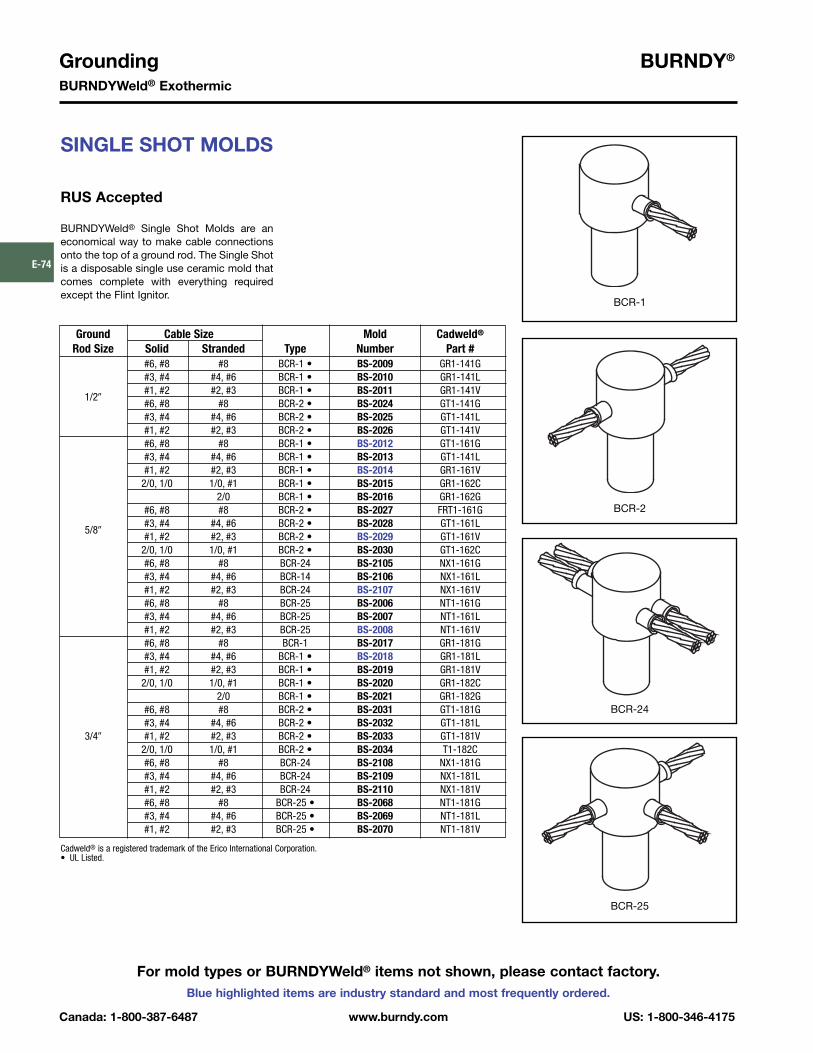
Grounding BURNDY®
BURNDYWeld® Exothermic
Canada: 1-800-387-6487 www.burndy.com US: 1-800-346-4175
Blue highlighted items are industry standard and most frequently ordered.
E-74
For mold types or BURNDYWeld® items not shown, please contact factory.
SINGLE SHOT MOLDS
RUS Accepted
BURNDYWeld® Single Shot Molds are aneconomical way to make cable connectionsonto the top of a ground rod. The Single Shotis a disposable single use ceramic mold thatcomes complete with everything requiredexcept the Flint Ignitor.
Ground Cable Size Mold Cadweld®
Rod Size Solid Stranded Type Number Part ##6, #8 #8 BCR-1 • BS-2009 GR1-141G#3, #4 #4, #6 BCR-1 • BS-2010 GR1-141L#1, #2 #2, #3 BCR-1 • BS-2011 GR1-141V
1/2�#6, #8 #8 BCR-2 • BS-2024 GT1-141G#3, #4 #4, #6 BCR-2 • BS-2025 GT1-141L#1, #2 #2, #3 BCR-2 • BS-2026 GT1-141V#6, #8 #8 BCR-1 • BS-2012 GT1-161G#3, #4 #4, #6 BCR-1 • BS-2013 GT1-141L#1, #2 #2, #3 BCR-1 • BS-2014 GR1-161V
2/0, 1/0 1/0, #1 BCR-1 • BS-2015 GR1-162C2/0 BCR-1 • BS-2016 GR1-162G
#6, #8 #8 BCR-2 • BS-2027 FRT1-161G#3, #4 #4, #6 BCR-2 • BS-2028 GT1-161L
5/8�#1, #2 #2, #3 BCR-2 • BS-2029 GT1-161V
2/0, 1/0 1/0, #1 BCR-2 • BS-2030 GT1-162C#6, #8 #8 BCR-24 BS-2105 NX1-161G#3, #4 #4, #6 BCR-14 BS-2106 NX1-161L#1, #2 #2, #3 BCR-24 BS-2107 NX1-161V#6, #8 #8 BCR-25 BS-2006 NT1-161G#3, #4 #4, #6 BCR-25 BS-2007 NT1-161L#1, #2 #2, #3 BCR-25 BS-2008 NT1-161V#6, #8 #8 BCR-1 BS-2017 GR1-181G#3, #4 #4, #6 BCR-1 • BS-2018 GR1-181L#1, #2 #2, #3 BCR-1 • BS-2019 GR1-181V
2/0, 1/0 1/0, #1 BCR-1 • BS-2020 GR1-182C2/0 BCR-1 • BS-2021 GR1-182G
#6, #8 #8 BCR-2 • BS-2031 GT1-181G#3, #4 #4, #6 BCR-2 • BS-2032 GT1-181L
3/4� #1, #2 #2, #3 BCR-2 • BS-2033 GT1-181V2/0, 1/0 1/0, #1 BCR-2 • BS-2034 T1-182C#6, #8 #8 BCR-24 BS-2108 NX1-181G#3, #4 #4, #6 BCR-24 BS-2109 NX1-181L#1, #2 #2, #3 BCR-24 BS-2110 NX1-181V#6, #8 #8 BCR-25 • BS-2068 NT1-181G#3, #4 #4, #6 BCR-25 • BS-2069 NT1-181L#1, #2 #2, #3 BCR-25 • BS-2070 NT1-181V
BCR-1
BCR-2
BCR-24
BCR-25
Cadweld® is a registered trademark of the Erico International Corporation.• UL Listed.

BURNDY® GroundingBURNDYWeld® Exothermic
US: 1-800-346-4175 www.burndy.com Canada: 1-800-387-6487
Blue highlighted items are industry standard and most frequently ordered.
E-75
For mold types or BURNDYWeld® items notshown, please contact factory.
TYPE BCS-1 MOLDS
Horizontal Cable to HorizontalSteel Surface
Type BCS-1 Molds are used to terminate a hor-izontal copper cable to any horizontal steel sur-face. Note that the cable is OFF the surface.
Size range is 1/0 through 1000 kcmil solid orconcentric stranded copper conductors.
Contact BURNDY® for information on moldsfor conductors not listed below.
Price Weld HandleCable Size Mold Number Key Metal Clamps
1/0 B-644 4 90 B-1062/0 B-645 4 90 B-1063/0 B-646 4 115 B-1064/0 B-647 4 115 B-106
250 kcmil B-648 4 115 B-106300 kcmil B-649 4 150 B-106350 kcmil B-650 4 200 B-106500 kcmil B-652 4 200 B-106750 kcmil B-653 5 2-150 B-1061000 kcmil B-654 5 2-200 B-107
Price Weld HandleCable Size Mold Number Key Metal Clamps
#6 B-628 3†** 45 N/A#4 B-629 3†* 45 N/A#2 B-630 3†* 45 N/A#1 B-631 3†* 65 N/A1/0 B-7146 4 90 B-1062/0 B-7075 4 90 B-1063/0 B-2199 4 115 B-1064/0 B-6114 4 115 B-106
250 kcmil B-2200 4 115 B-106300 kcmil B-2506 4 150 B-106350 kcmil B-2507 4 200 B-106500 kcmil B-2509 4 200 B-106750 kcmil B-2542 5 2-150 B-1071000 kcmil B-2511 5 2-200 B-107
• For sizes not listed, contact BURNDY®.• Molds listed are for concentric stranded cable. Add suffix “-S” to mold number for solid
conductors.• For heavy duty molds, molds with wear plates or molds for Copperweld® cable, contact
BURNDY®.• For expedited service, contact BURNDY®.Required Tools:
Handle Clamps (see chart for correct handles)B38-0309-00 Flint Ignitor
Other recommended accessories:B38-3922-00 Mold Cleaning Brush (pg E-92)B38-0135-00 Cable Cleaning Brush (pg E-92)B38-0330-00 Cable Clamp (pg E-92)B38-0101-00 Rasp (pg E-93)
• For sizes not listed, contact BURNDY®.• Molds listed are for concentric stranded cable. Add suffix “-S” to mold number for solid
conductors.• For heavy duty molds, molds with wear plates or molds for Copperweld® cable, contact
BURNDY®.• For expedited service, contact BURNDY®.Required Tools:
Handle Clamps (see chart for correct handles)† Sold complete with frame* B38-0309-00 Flint Ignitor (included)
Other recommended accessories:B38-3922-00 Mold Cleaning Brush (pg E-92)B38-0135-00 Cable Cleaning Brush (pg E-92)B38-0330-00 Cable Clamp (pg E-92)B38-0101-00 Rasp (pg E-93)
TYPE BCS-8 MOLDS
Horizontal Cable to HorizontalSteel Surface
Type BCS-8 Molds are used to terminate ahorizontal copper cable to any horizontalsteel surface. Note that the cable is ON thesurface.
Size range is #6 through 1000 kcmil solid orconcentric stranded copper conductors.
Contact BURNDY® for information on moldsfor conductors not listed below.

Grounding BURNDY®
BURNDYWeld® Exothermic
Canada: 1-800-387-6487 www.burndy.com US: 1-800-346-4175
Blue highlighted items are industry standard and most frequently ordered.
E-76
For mold types or BURNDYWeld® items notshown, please contact factory.
TYPE BCS-2 MOLDS
Horizontal Through Cable toHorizontal Steel Surface
Type BCS-2 Molds are used to join horizontalthrough copper cable to any horizontal steelsurface. Note the cable is OFF the surface.
Size range is 1/0 through 1000 kcmil solid orconcentric stranded copper conductors.
Contact BURNDY® for information on moldsfor conductors not listed below.
Price Weld HandleCable Size Mold Number Key Metal Clamps
1/0 B-616 4 90 B-1062/0 B-617 4 115 B-1063/0 B-618 4 115 B-1064/0 B-619 4 150 B-106
250 kcmil B-620 4 150 B-106300 kcmil B-621 4 200 B-106350 kcmil B-622 4 250 B-106500 kcmil B-624 5 2-150 B-107750 kcmil B-625-H 5 3-250 B-1071000 kcmil B-626-H 5 2-500 B-107
Price Weld HandleCable Size Mold Number Key Metal Clamps
#6 B-602 3†* 45 N/A#4 B-603 3†* 45 N/A#2 B-604 3†* 45 N/A#1 B-605 3†* 65 N/A1/0 B-8379 4 90 B-1062/0 B-5331 4 115 B-1063/0 B-8381 4 115 B-1064/0 B-7192 4 150 B-106
250 kcmil B-8413 4 150 B-106300 kcmil B-8423 4 200 B-106350 kcmil B-8410 4 250 B-106500 kcmil B-5065 5 2-150 B-107
• For sizes not listed, contact BURNDY®.• Molds listed are for concentric stranded cable. Add suffix “-S” to mold number for solid
conductors.• For heavy duty molds, molds with wear plates or molds for Copperweld® cable, contact
BURNDY®.• For expedited service, contact BURNDY®.Required Tools:
Handle Clamps (see above for correct handles)B38-0309-00 Flint Ignitor
Other recommended accessories:B38-3922-00 Mold Cleaning Brush (pg E-92)B38-0135-00 Cable Cleaning Brush (pg E-92)B38-0101-00 Rasp (pg E-93)
• For sizes not listed, contact BURNDY®.• Molds listed are for concentric stranded cable. Add suffix “-S” to mold number for solid
conductors.• For heavy duty molds, molds with wear plates or molds for Copperweld® cable, contact
BURNDY®.• For expedited service, contact BURNDY®.Required Tools:
Handle Clamps (see chart for correct handles)† Sold complete with handle frame* B38-0309-00 Flint Ignitor (included)
Other recommended accessories:B40-0319-01 Mold Cleaner for cartridge sizes #15-#65 (pg E-92)B40-0319-03 Mold Cleaner for cartridge sizes #90-#500 (pg E-92)B38-3922-00 Mold Cleaning Brush (pg E-92)B38-0135-00 Cable Cleaning Brush (pg E-92)B38-0101-00 Rasp (pg E-93)
TYPE BCS-9 MOLDS
Horizontal Through Cable toHorizontal Steel Surface
Type BCS-9 Molds are used to join horizontalthrough copper cable to any horizontal steelsurface. Note the cable is ON the surface.
Size range is #6 through 500 kcmil solid orconcentric stranded copper conductors.
Contact BURNDY® Products for informationon molds for conductors not listed below.

BURNDY® GroundingBURNDYWeld® Exothermic
US: 1-800-346-4175 www.burndy.com Canada: 1-800-387-6487
Blue highlighted items are industry standard and most frequently ordered.
E-77
TYPE BCS-3 MOLDS
Angular Cable Drop to VerticalSteel Surface
Type BCS-3 Molds are used to join the end ofa copper cable at a 45˚ angle to a verticalsteel surface.
Size range is #6 through 1000 kcmil solid orconcentric stranded copper conductors.
Contact BURNDY® for information on moldsfor conductors not listed below.
Price Weld HandleCable Size Mold Number Key Metal Clamps
#6 B-585 4 45 B-106#4 B-586 4 45 B-106#3 B-587 4 45 B-106#2 B-588 4 45 B-106#1 B-589 4 65 B-1061/0 B-590 4 90 B-1062/0 B-591 4 90 B-1063/0 B-592 4 115 B-1064/0 B-593 4 115 B-106
250 kcmil B-594 4 115 B-106300 kcmil B-595 4 150 B-106350 kcmil B-596 4 200 B-106500 kcmil B-598 4 200 B-106750 kcmil B-599 5 2-150 B-1071000 kcmil B-600 5 2-200 B-107
Cable Pipe Mold Price Weld HandleSize Size Number Key Metal Clamps
1-1/4� to 4� B-2476 4 45 B-1064� to 6� B-2477 4 45 B-106
#46� to 10� B-2478 4 45 B-10612� & up B-586 ‡ 4 45 B-106
1-1/4� to 4� B-9233-S 4 45 B-1064� to 6� B-2480-S 4 45 B-106
#2 Sol6� to 10� B-2583-S 4 45 B-10612� & up B-588-S ‡ 4 45 B-106
1-1/4� to 4� B-9233 4 45 B-1064� to 6� B-2480 4 45 B-106
#26� to 10� B-2583 4 45 B-10612� & up B-588 ‡ 4 45 B-106
1-1/4� to 4� B-2482 4 65 B-1064� to 6� B-2483 4 65 B-106
#16� to 10� B-2484 4 65 B-10612� & up B-589 ‡ 4 65 B-106
1-1/4� to 4� B-2486 4 90 B-1064� to 6� B-2487 4 90 B-106
1/06� to 10� B-2488 4 90 B-10612� & up B-590 ‡ 4 90 B-106
1-1/4� to 4� B-8833 4 90 B-1064� to 6� B-2490 4 90 B-106
2/06� to 10� B-2491 4 90 B-10612� & up� B-591 ‡ 4 90 B-106
1-1/4� to 4� B-2493 4 115 B-1064� to 6� B-2494 4 115 B-106
3/06� to 10� B-2495 4 115 B-10612� & up B-592 ‡ 4 115 B-106
1-1/4� to 4� B-9021 4 115 B-1064� to 6� B-2497 4 115 B-106
4/06� to 10� B-2498 4 115 B-10612� & up B-593 ‡ 4 115 B-106
• For sizes not listed, contact BURNDY®.• Molds listed are for concentric stranded cable. Add suffix “-S” to mold number for solid
conductors.• For heavy duty molds, molds with wear plates or molds for Copperweld® cable, contact
BURNDY®.• For expedited service, contact BURNDY®.Required Tools:
Handle Clamps (see chart for correct handles)B38-0309-00 Flint Ignitor
Other recommended accessories:Magnetic Clamps to hold molds against vertical steel (pg E-89)B38-3922-00 Mold Cleaning Brush (pg E-92)B38-0135-00 Cable Cleaning Brush (pg E-92)B38-0101-00 Rasp (pg E-93)
• For sizes not listed, contact BURNDY®.• Molds listed are for concentric stranded cable. Add suffix “-S” to mold number for solid
conductors.• For heavy duty molds, molds with wear plates or molds for Copperweld® cable, contact
BURNDY®.• For expedited service, contact BURNDY®.Required Tools:
Handle Clamps (see chart for correct handles)B38-0309-00 Flint Ignitor
Other recommended accessories:B106-32 Vertical Chain Clamp w/ B-106 Handles for 4� Pipe & smallerB40-0106-27 20� Chain Extension for 4� to 10� Pipe
Use (2) 20� Chain Extensions for pipe sizes between 10� and 16�B38-3922-00 Mold Cleaning Brush (pg E-92)B38-0135-00 Cable Cleaning Brush (pg E-92)B38-0101-00 Rasp (pg E-93)
‡ Flat Surface Mold
Cable to Flat Steel Cable to Pipe
Cable to Flat Steel Cable to Pipe
For mold types or BURNDYWeld® items notshown, please contact factory.

Grounding BURNDY®
BURNDYWeld® Exothermic
Canada: 1-800-387-6487 www.burndy.com US: 1-800-346-4175
Blue highlighted items are industry standard and most frequently ordered.
E-78
For mold types or BURNDYWeld® items not shown, please contact factory.
TYPE BCS-23 MOLDS
Vertical Cable Drop to Vertical Steel Surface
Type BCS-23 Molds are used to join verticalcable down to a vertical steel surface. Notethat the cable is OFF the surface.
Size range is #6 through 500 kcmil solid orconcentric stranded copper conductors.
Contact BURNDY® for information on moldsfor conductors not listed below.
Price Weld HandleCable Size Mold Number Key Metal Clamps
#6 B-5389 4 45 B-106#4 B-5359 4 65 B-106#2 B-2781 4 65 B-106#1 B-5361 4 90 B-1061/0 B-2189 4 115 B-1062/0 B-2540 4 115 B-1063/0 B-5362 4 150 B-1064/0 B-8718 4 150 B-106
250 kcmil B-8165 4 200 B-106300 kcmil B-5363 4 200 B-106350 kcmil B-9029 4 250 B-106500 kcmil B-8512 17 2-150 B-106
• For sizes not listed, contact BURNDY®.• Molds listed are for concentric stranded cable. Add suffix “-S” to mold number for solid
conductors.• For heavy duty molds, molds with wear plates or molds for Copperweld® cable, contact
BURNDY®.• For expedited service, contact BURNDY®.Required Tools:
Handle Clamps (see chart for correct handles)B38-0309-00 Flint Ignitor
Other recommended accessories:Magnetic Clamps to hold molds against vertical steelB38-3922-00 Mold Cleaning Brush (pg E-92)B38-0135-00 Cable Cleaning Brush (pg E-92)B38-0101-00 Rasp (pg E-93)

BURNDY® GroundingBURNDYWeld® Exothermic
US: 1-800-346-4175 www.burndy.com Canada: 1-800-387-6487
Blue highlighted items are industry standard and most frequently ordered.
E-79
For mold types or BURNDYWeld® items not shown, please contact factory.
TYPE BCS-4 MOLDS
Vertical Through Cable toVertical Steel Surface
Type BCS-4 Molds are used to join a verticalthrough copper cable to a vertical steel sur-face. Note that the cable is OFF the surface.For molds with the cable on the surface, con-tact BURNDY® Products.
Size range is #6 through 500 kcmil solid orconcentric stranded copper conductors.
Contact BURNDY® for information on moldsfor conductors not listed below.
Price Weld HandleCable Size Mold Number Key Metal Clamps
#6 B-1215 4 90 B-106#4 B-1216 4 90 B-106#2 B-1218 4 115 B-106#1 B-1219 4 115 B-1061/0 B-1220 17 200 B-1062/0 B-1221 17 200 B-1063/0 B-1222 17 250 B-1064/0 B-1223 17 250 B-106
250 kcmil B-1224 17 250 B-106300 kcmil B-1225-H 6 500 B-107350 kcmil B-1226-H 6 3-200 B-107500 kcmil B-1228-H 6 3-250 B-107
Price Weld HandleCable Size Mold Number Key Metal Clamps
#6 B-1626 4 65 B-106#4 B-1627 4 65 B-106#2 B-1628 4 65 B-106#1 B-1629 4 90 B-1061/0 B-1630 4 115 B-1062/0 B-1631 4 115 B-1063/0 B-1632 4 150 B-1064/0 B-1633 4 150 B-106
250 kcmil B-1634 4 150 B-106
• For sizes not listed, contact BURNDY®.• Molds listed are for concentric stranded cable. Add suffix “-S” to mold number for solid
conductors.• For heavy duty molds, molds with wear plates or molds for Copperweld® cable, contact
BURNDY®.• For expedited service, contact BURNDY®.Required Tools:
Handle Clamps (see chart for correct handles)B38-0309-00 Flint Ignitor
Other recommended accessories:Magnetic Clamps to hold molds against vertical steelB38-3922-00 Mold Cleaning Brush (pg E-92)B38-0135-00 Cable Cleaning Brush (pg E-92)B38-0101-00 Rasp (pg E-93)
• For sizes not listed, contact BURNDY®.• Molds listed are for concentric stranded cable. Add suffix “-S” to mold number for solid
conductors.• For heavy duty molds, molds with wear plates or molds for Copperweld® cable, contact
BURNDY®.• For expedited service, contact BURNDY®.Required Tools:
Handle Clamps (see chart for correct handles)B38-0309-00 Flint Ignitor
Other recommended accessories:B40-0319-01 Mold Cleaner for cartridge sizes #15-#65 (pg E-92)B40-0319-03 Mold Cleaner for cartridge sizes #90-#500 (pg E-92)B38-3922-00 Mold Cleaning Brush (pg E-92)B38-0135-00 Cable Cleaning Brush (pg E-92)B38-0101-00 Rasp (pg E-93)
TYPE BCS-6 MOLDS
Horizontal Through Cable toVertical Steel Surface
Type BCS-6 Molds are used to join horizontalthrough copper cable to a vertical steel sur-face. Note that the cable is OFF the surface.
Size range is #6 through 250 kcmil solid orconcentric stranded copper conductors.
Contact BURNDY® for information on moldsfor conductors not listed below.

Grounding BURNDY®
BURNDYWeld® Exothermic
Canada: 1-800-387-6487 www.burndy.com US: 1-800-346-4175
Blue highlighted items are industry standard and most frequently ordered.
E-80
TYPE BCS-7 MOLDS
Overhead Vertical Tap Cableto Vertical Steel Surface
Type BCS-7 Molds are used to join an over-head vertical copper conductor drop tap to avertical steel surface.
Size range is #6 through 1000 kcmil solid orconcentric stranded copper conductors.
Contact BURNDY® for information on moldsfor conductors not listed below.
Price Weld HandleCable Size Mold Number Key Metal Clamps
#6 B-1635 4 65 B-106#4 B-1636 4 65 B-106#3 B-1637 4 65 B-106#2 B-1638 4 65 B-106#1 B-1639 4 90 B-1061/0 B-1640 4 150 B-1062/0 B-1641 4 150 B-1063/0 B-1642 17 200 B-1064/0 B-1643 17 200 B-106
250 kcmil B-1644 17 200 B-106300 kcmil B-1645 17 250 B-106350 kcmil B-1646 6 2-150 B-107500 kcmil B-1648 6 2-200 B-107750 kcmil B-1649 6 500 B-1071000 kcmil B-1650 6 3-200 B-107
Price Weld HandleCable Size Mold Number Key Metal Clamps
#6 B-5910 4 45 B-106#4 B-2761 4 45 B-106#2 B-2569 4 45 B-106#1 B-6060 4 65 B-1061/0 B-5419 4 90 B-1062/0 B-2567 4 90 B-1063/0 B-6072 4 115 B-1064/0 B-9253 4 115 B-106
250 kcmil B-2568 4 115 B-106300 kcmil B-6061 4 150 B-106350 kcmil B-6067 4 200 B-106500 kcmil B-8359 4 200 B-106
• For sizes not listed, contact BURNDY®.• Molds listed are for concentric stranded cable. Add suffix “-S” to mold number for solid
conductors.• For heavy duty molds, molds with wear plates or molds for Copperweld® cable, contact
BURNDY®.• For expedited service, contact BURNDY®.Required Tools:
Handle Clamps (see chart for correct handles)B38-0309-00 Flint Ignitor
Other recommended accessories:Magnetic Clamps to hold molds against vertical steelB38-3922-00 Mold Cleaning Brush (pg E-92)B38-0135-00 Cable Cleaning Brush (pg E-92)B38-0101-00 Rasp (pg E-93)
NOTE: Add (-R) to mold number for right hand mold or (-L) for left hand mold. Right hand (-R)mold will be furnished if not specified.
• For sizes not listed, contact BURNDY®.• Molds listed are for concentric stranded cable. Add suffix “-S” to mold number for solid
conductors.• For heavy duty molds, molds with wear plates or molds for Copperweld® cable, contact
BURNDY®.• For expedited service, contact BURNDY®.Required Tools:
Handle Clamps (see chart for correct handles)B38-0309-00 Flint Ignitor
Other recommended accessories:Vertical Chain ClampsB38-3922-00 Mold Cleaning Brush (pg E-92)B38-0135-00 Cable Cleaning Brush (pg E-92)B38-0101-00 Rasp (pg E-93)
TYPE BCS-18 MOLDS
Horizontal Tap Cable toVertical Steel Surface
Type BCS-18 Molds are used to connect ahorizontal conductor to a vertical steel sur-face. Note that the cable is ON the surface.
Size range is #6 through 500 kcmil solid orconcentric stranded copper conductors.
Contact BURNDY® for information on moldsfor conductors not listed below.
For mold types or BURNDYWeld® items notshown, please contact factory.

BURNDY® GroundingBURNDYWeld® Exothermic
US: 1-800-346-4175 www.burndy.com Canada: 1-800-387-6487
Blue highlighted items are industry standard and most frequently ordered.
E-81
TYPE BCS-5 MOLDS
Horizontal Cable Tap toHorizontal Cast Iron Surface
Type BCS-5 Molds are used to join horizon-tal cable taps to horizontal cast iron surfaces.Note that the cable is ON the surface.
Size range is #6 through #1 solid or concen-tric stranded copper conductors.
Contact BURNDY® for information on moldsfor conductors not listed below.
Price Weld HandleCable Size Mold Number Key Metal Clamps
#6 Sol B-1613 3+ 2SCI N/A#6 B-1614 3+ 25CI N/A
#4 Sol B-1615 3+ 45CI N/A#4 B-1616 3+ 45CI N/A
#2 Sol B-1617 3+ 45CI N/A#2 B-1618 3+ 45CI N/A
#1 Sol B-1619 3+ 65CI N/A#1 B-1620 3+ 65CI N/A
• For sizes not listed, contact BURNDY®.• Molds listed are for concentric stranded cable. Add suffix “-S” to mold number for solid
conductors.• For heavy duty molds, molds with wear plates or molds for Copperweld® cable, contact
BURNDY®.• For expedited service, contact BURNDY®.Required Tools:
† Sold complete with frameB38-0309-00 Flint Ignitor (included)
Other recommended accessories:B38-3922-00 Mold Cleaning Brush (pg E-92)B38-0135-00 Cable Cleaning Brush (pg E-92)B38-0101-00 Rasp (pg E-93)
DO NOT use Type BCS-5 molds on Soil Pipe (ASTM A74-82). Atest weld should be made on a section of the pipe being usedto determine the possibility of detrimental metallurgical effects.
For mold types or BURNDYWeld® items not shown, please contact factory.

Grounding BURNDY®
BURNDYWeld® Exothermic
Canada: 1-800-387-6487 www.burndy.com US: 1-800-346-4175
Blue highlighted items are industry standard and most frequently ordered.
E-82
For mold types or BURNDYWeld® items not shown, please contact factory.
TYPE BCRE-1 MOLDS
Horizontal Parallel Tap to Rebar
Type BCRE-1 Molds are recommended forparallel, horizontal connections for solid orconcentric stranded conductors #6 through4/0 joined to reinforcing bars #3 through #6and larger. The high copper content joint hasa higher current carrying capacity than theconductors being joined and is impervious tovibration and moisture.
Contact BURNDY® for information on moldsfor conductors not listed below.
Rebar Cable Mold Packing Price Weld HandleSize Size Number Material ‡ Key Metal Clamps
#6 B-7500 B38032900 4 25 B-106#4 B-7501 B38032900 4 32 B-106#2 B-7502 B38032900 4 45 B-106#1 B-7503 B38032900 4 65 B-106
#31/0 B-7504 B38032900 4 90 B-1062/0 B-7505 B38032900 4 90 B-1063/0 B-7506 B38032900 4 115 B-1064/0 B-7507 B38032900 4 115 B-106#6 B-7508 B38406100 3+ 25 N/A
#4#4 B-7509 B38406100 3+ 32 N/A
 B-7510 B38406100 3+ 45 N/A
Larger#1 B-7511 B38406100 3+ 65 N/A1/0 B-7512 B38032900 4 90 B-1062/0 B-7513 B38032900 4 90 B-106
#43/0 B-7514 B38032900 4 115 B-1064/0 B-7515 B38032900 4 115 B-1061/0 B-7520 B38032900 4 90 B-1062/0 B-7521 B38032900 4 90 B-106
#53/0 B-7522 B38032900 4 115 B-1064/0 B-7523 B38032900 4 115 B-1061/0 B-7528 B38406200 14+ 90 N/A
#62/0 B-7529 B38406200 14+ 90 N/A
&3/0 B-7530 B38406200 14+ 115 N/A
Larger4/0 B-7531 B38406200 14+ 115 N/A
• For sizes not listed, contact BURNDY®.• Molds listed are for concentric stranded cable. Add suffix “-S” to mold number for solid
conductors.• For heavy duty molds, molds with wear plates or molds for Copperweld® cable, contact
BURNDY®.• For expedited service, contact BURNDY®.Required Tools:
Handle Clamps (see chart for correct handles)† Sold complete with frameB38-0309-00 Flint Ignitor
Other recommended accessories:B38-3922-00 Mold Cleaning Brush (pg E-92)B38-0135-00 Cable Cleaning Brush (pg E-92)B38-0304-00 File (pg E-93)
‡ PACKING MATERIAL NOTE
A packing pad is necessary when mak-ing BURNDYWeld® connections torebar. Packing material B38032900 iscopper shim stock. Packing materialnumbers B38406100, B38406200 andB38406300 are a ceramic fiber materialand can be used for one connectiononly. Be sure to specify packing materi-al catalog number when ordering moldand weld metal.

BURNDY® GroundingBURNDYWeld® Exothermic
US: 1-800-346-4175 www.burndy.com Canada: 1-800-387-6487
Blue highlighted items are industry standard and most frequently ordered.
E-83
TYPE BCRE-2 MOLDS
Horizontal Cable Tap toHorizontal Rebar Run
Type BCRE-2 Molds are recommended forright angle, horizontal connections for solidor concentric stranded conductors #6through 4/0 joined to reinforcing bars #3through #6. The high copper content jointhas a higher current carrying capacity thanthe conductors being joined and is impervi-ous to vibration and moisture.
Rebar Cable Mold Packing Price Weld HandleSize Size Number Material ‡ Key Metal Clamps
#6 B-7588 B38032900 4 45 B-106#4 B-7589 B38032900 4 45 B-106#2 B-7590 B38032900 4 65 B-106#1 B-7591 B38032900 4 65 B-106
#31/0 B-7592 B38032900 4 90 B-1062/0 B-7593 B38032900 4 90 B-1063/0 B-7594 B38032900 4 115 B-1064/0 B-7595 B38032900 4 115 B-106#6 B-7596 B38032900 4 45 B-106#4 B-7597 B38032900 4 45 B-106#2 B-7598 B38032900 4 65 B-106#1 B-7599 B38032900 4 65 B-106
#41/0 B-7600 B38032900 4 90 B-1062/0 B-7601 B38032900 4 90 B-1063/0 B-7602 B38032900 4 115 B-1064/0 B-7603 B38032900 4 115 B-106#6 B-7604 B38032900 4 90 B-106#4 B-7605 B38032900 4 90 B-106#2 B-7606 B38032900 4 90 B-106#1 B-7607 B38032900 4 90 B-106
#51/0 B-7608 B38032900 4 115 B-1062/0 B-7609 B38032900 4 115 B-1063/0 B-7610 B38032900 4 150 B-1064/0 B-7611 B38032900 4 150 B-106#6 B-7612 B38032900 4 90 B-106#4 B-7613 B38032900 4 90 B-106#2 B-7614 B38032900 4 90 B-106#1 B-7615 B38032900 4 90 B-106
#61/0 B-7616 B38032900 4 115 B-1062/0 B-7617 B38032900 4 115 B-1063/0 B-7618 B38032900 4 150 B-1064/0 B-7619 B38032900 4 150 B-106
• For sizes not listed, contact BURNDY®.• Molds listed are for concentric stranded cable. Add suffix
“-S” to mold number for solid conductors.• For heavy duty molds, molds with wear plates or molds
for Copperweld® cable, contact BURNDY®.• For expedited service, contact BURNDY®.Required Tools:
Handle Clamps (see chart for correct handles)B38-0309-00 Flint Ignitor
‡ PACKING MATERIAL NOTE
A packing pad is necessary when mak-ing BURNDYWeld® connections torebar. Packing material B38032900 iscopper shim stock. Packing materialnumbers B38406100, B38406200 andB38406300 are a ceramic fiber materialand can be used for one connectiononly. Be sure to specify packing materi-al catalog number when ordering moldand weld metal.
For mold types or BURNDYWeld® items not shown, please contact factory.
Contact BURNDY® for information on moldsfor conductors not listed below.
Other recommended accessoriesB40-0319-01 Mold Cleaner for cartridge sizes #15-#65(pg E-92)B40-0319-03 Mold Cleaner for cartridge sizes #90-#500(pg E-92)B38-3922-00 Mold Cleaning Brush (pg E-92)B38-0135-00 Cable Cleaning Brush (pg E-92)B38-0304-00 File (pg E-93)

Grounding BURNDY®
BURNDYWeld® Exothermic
Canada: 1-800-387-6487 www.burndy.com US: 1-800-346-4175
Blue highlighted items are industry standard and most frequently ordered.
E-84
TYPE BCRE-3 MOLDS
Horizontal through Cable toVertical Rebar
Type BCRE-3 Molds are recommended forhorizontal conductors to vertical rebar con-nections for solid or concentric stranded con-ductors #6 through 4/0 joined to reinforcingbars #3 through #7 & larger. The high coppercontent joint has a higher current carryingcapacity than the conductors being joinedand is impervious to vibration and moisture.
Contact BURNDY® for information on moldsfor conductors not listed below.
Rebar Cable Mold Packing Price Weld HandleSize Size Number Material ‡ Key Metal Clamps
#6 B-7620 B38032900 24 90 B-106#4 B-7621 B38032900 24 90 B-106#2 B-7622 B38032900 24 90 B-106#1 B-7623 B38032900 24 115 B-106
#31/0 B-7624 B38032900 24 115 B-1062/0 B-7625 B38032900 24 115 B-1063/0 B-7626 B38032900 24 150 B-1064/0 B-7627 B38032900 24 150 B-106#6 B-7628 B38032900 24 90 B-106#4 B-7629 B38032900 24 90 B-106#2 B-7630 B38032900 24 90 B-106#1 B-7631 B38032900 24 115 B-106
#41/0 B-7632 B38032900 24 115 B-1062/0 B-7633 B38032900 24 115 B-1063/0 B-7634 B38032900 24 150 B-1064/0 B-7635 B38032900 24 150 B-106#6 B-7636 B38032900 24 90 B-106#4 B-7637 B38032900 24 90 B-106#2 B-7638 B38032900 24 90 B-106#1 B-7639 B38032900 24 115 B-106
#51/0 B-7640 B38032900 24 115 B-1062/0 B-7641 B38032900 24 115 B-106v3/0 B-7642 B38032900 24 150 B-1064/0 B-7643 B38032900 24 150 B-106#6 B-7644 B38032900 24 90 B-106#4 B-7645 B38032900 24 90 B-106#2 B-7646 B38032900 24 90 B-106#1 B-7647 B38032900 24 115 B-106
#61/0 B-7648 B38032900 24 115 B-1062/0 B-7649 B38032900 24 115 B-1063/0 B-7650 B38032900 24 150 B-1064/0 B-7651 B38032900 24 150 B-106#6 B-7652 B38406300 4+ 90 B-106-41#4 B-7653 B38406300 4+ 90 B-106-41#2 B-7654 B38406300 4+ 90 B-106-41
#7#1 B-7655 B38406300 4+ 115 B-106-41
&1/0 B-7656 B38406300 4+ 115 B-106-41
Larger2/0 B-7657 B38406300 4+ 115 B-106-413/0 B-7658 B38406300 4+ 150 B-106-414/0 B-7659 B38406300 4+ 150 B-106-41
• For sizes not listed, contact BURNDY®.• Molds listed are for concentric stranded cable. Add suffix
“-S” to mold number for solid conductors.• For heavy duty molds, molds with wear plates or molds
for Copperweld® cable, contact BURNDY®.• For expedited service, contact BURNDY®.Required Tools:
Handle Clamps (see chart for correct handles)B38-0309-00 Flint Ignitor
Other recommended accessories:Vertical Chain Clamps† B40-0319-03 Mold Cleaner for cartridge sizes #90-#500 (pg E-92)B38-3922-00 Mold Cleaning Brush (pg E-92)B38-0135-00 Cable Cleaning Brush (pg E-92)B38-0304-00 File (pg E-93)
‡ PACKING MATERIAL NOTE
A packing pad is necessary when mak-ing BURNDYWeld® connections torebar. Packing material B38032900 iscopper shim stock. Packing materialnumbers B38406100, B38406200 andB38406300 are a ceramic fiber materialand can be used for one connectiononly. Be sure to specify packing materi-al catalog number when ordering moldand weld metal.
For mold types or BURNDYWeld® items not shown, please contact factory.

BURNDY® GroundingBURNDYWeld® Exothermic
US: 1-800-346-4175 www.burndy.com Canada: 1-800-387-6487
Blue highlighted items are industry standard and most frequently ordered.
E-85
TYPE BCRE-4 MOLDS
Horizontal through Cable toHorizontal Rebar
Type BCRE-4 Molds are recommended forhorizontal through conductors to horizontalrebar at right angle connections for solid orconcentric stranded conductors #6 through4/0 joined to reinforcing bars #3 through #6 &larger. The high copper content joint has ahigher current carrying capacity than theconductors being joined and is impervious tovibration and moisture.
Contact BURNDY® for information on moldsfor conductors not listed below.
Rebar Cable Mold Packing Price Weld HandleSize Size Number Material ‡ Key Metal Clamps
#6 B-7708 B38032900 4 90 B-106#4 B-7709 B38032900 4 90 B-106#2 B-7710 B38032900 4 90 B-106#1 B-7711 B38032900 4 115 B-106
#31/0 B-7712 B38032900 22 115 B-1062/0 B-7713 B38032900 22 115 B-1063/0 B-7714 B38032900 22 150 B-1064/0 B-7715 B38032900 22 150 B-106#6 B-7716 B38032900 4 90 B-106#4 B-7717 B38032900 4 90 B-106#2 B-7718 B38032900 4 90 B-106#1 B-7719 B38032900 22 115 B-106
#41/0 B-7720 B38032900 22 115 B-1062/0 B-7721 B38032900 22 115 B-1063/0 B-7722 B38032900 22 150 B-1064/0 B-7723 B38032900 22 150 B-106#6 B-7724 B38032900 4 90 B-106#4 B-7725 B38032900 4 90 B-106#2 B-7726 B38032900 4 90 B-106#1 B-7727 B38032900 22 115 B-106
#51/0 B-7728 B38032900 22 115 B-1062/0 B-7729 B38032900 22 115 B-1063/0 B-7730 B38032900 22 150 B-1064/0 B-7731 B38032900 22 150 B-106#6 B-7732 B38406100 14+ 90 N/A#4 B-7733 B38406100 14+ 90 N/A#2 B-7734 B38406100 14+ 90 N/A
#6#1 B-7735 B38406100 14+ 115 N/A
&1/0 B-7736 B38406200 14+ 115 N/A
Larger2/0 B-7737 B38406200 14+ 115 N/A3/0 B-7738 B38406200 14+ 150 N/A4/0 B-7739 B38406200 14+ 150 N/A
• For sizes not listed, contact BURNDY®.• Molds listed are for concentric stranded cable. Add suffix
“-S” to mold number for solid conductors.• For heavy duty molds, molds with wear plates or molds
for Copperweld® cable, contact BURNDY®.• For expedited service, contact BURNDY®.Required Tools:
Handle Clamps (see chart for correct handles)† Sold complete with frameB38-0309-00 Flint Ignitor
‡ PACKING MATERIAL NOTE
A packing pad is necessary when mak-ing BURNDYWeld® connections torebar. Packing material B38032900 iscopper shim stock. Packing materialnumbers B38406100, B38406200 andB38406300 are a ceramic fiber materialand can be used for one connectiononly. Be sure to specify packing materi-al catalog number when ordering moldand weld metal.
For mold types or BURNDYWeld® items not shown, please contact factory.
Other recommended accessories:B40-0319-03 Mold Cleaner for cartridge sizes #90-#500(pg E-92)B38-3922-00 Mold Cleaning Brush (pg E-92)B38-0135-00 Cable Cleaning Brush (pg E-92)B38-0304-00 File (pg E-93)

Grounding BURNDY®
BURNDYWeld® Exothermic
Canada: 1-800-387-6487 www.burndy.com US: 1-800-346-4175
Blue highlighted items are industry standard and most frequently ordered.
E-86
For mold types or BURNDYWeld® items not shown, please contact factory.
TYPE BCRE-6 MOLDS
Horizontal Cable Tap toVertical Rebar
Type BCRE-6 Molds are recommended forhorizontal conductors terminating at rightangles to vertical rebar connections for solidor concentric stranded conductors #6through 4/0 joined to reinforcing bars #3through #7 and larger. The high copper con-tent joint has a higher current carryingcapacity than the conductors being joinedand is impervious to vibration and moisture.
Contact BURNDY® for information on moldsfor conductors not listed below.
Rebar Cable Mold Packing Price Weld HandleSize Size Number Material ‡ Key Metal Clamps
#6 B-7884 B38032900 4 90 B-106#4 B-7885 B38032900 4 90 B-106#2 B-7886 B38032900 4 90 B-106#1 B-7887 B38032900 4 115 B-106
#31/0 B-7888 B38032900 4 115 B-1062/0 B-7889 B38032900 4 115 B-1063/0 B-7890 B38032900 4 150 B-1064/0 B-7891 B38032900 4 150 B-106#6 B-7892 B38032900 4 90 B-106#4 B-7893 B38032900 4 90 B-106#2 B-7894 B38032900 4 90 B-106#1 B-7895 B38032900 4 115 B-106
#41/0 B-7896 B38032900 4 115 B-1062/0 B-7897 B38032900 4 115 B-1063/0 B-7898 B38032900 4 150 B-1064/0 B-7899 B38032900 4 150 B-106#6 B-7900 B38032900 4 90 B-106#4 B-7901 B38032900 4 90 B-106#2 B-7902 B38032900 4 90 B-106#1 B-7903 B38032900 4 115 B-106
#51/0 B-7904 B38032900 4 115 B-1062/0 B-7905 B38032900 4 115 B-1063/0 B-7906 B38032900 4 150 B-1064/0 B-7907 B38032900 4 150 B-106#6 B-7908 B38032900 4 90 B-106#4 B-7909 B38032900 4 90 B-106#2 B-7910 B38032900 4 90 B-106#1 B-7911 B38032900 4 115 B-106
#61/0 B-7912 B38032900 4 115 B-1062/0 B-7913 B38032900 4 115 B-1063/0 B-7914 B38032900 4 150 B-1064/0 B-7915 B38032900 4 150 B-106#6 B-7916 B38406300 4 90 B-106-32#4 B-7917 B38406300 4 90 B-106-32#2 B-7918 B38406300 4 90 B-106-32
#7#1 B-7919 B38406300 4 115 B-106-32
&1/0 B-7920 B38406300 4 115 B-106-32
Larger2/0 B-7921 B38406300 4 115 B-106-323/0 B-7922 B38406300 4 150 B-106-324/0 B-7923 B38406300 4 150 B-106-32
• For sizes not listed, contact BURNDY®.• Molds listed are for concentric stranded cable. Add suffix
“-S” to mold number for solid conductors.• For heavy duty molds, molds with wear plates or molds
for Copperweld® cable, contact BURNDY®.• For expedited service, contact BURNDY®.Required Tools:
Handle Clamps (see chart for correct handles)B38-0309-00 Flint Ignitor
Other recommended accessories:B38-3922-00 Mold Cleaning Brush (pg E-92)B38-0135-00 Cable Cleaning Brush (pg E-92)B38-0304-00 File (pg E-93)
‡ PACKING MATERIAL NOTE
A packing pad is necessary when mak-ing BURNDYWeld® connections torebar. Packing material B38032900 iscopper shim stock. Packing materialnumbers B38406100, B38406200 andB38406300 are a ceramic fiber materialand can be used for one connectiononly. Be sure to specify packing materi-al catalog number when ordering moldand weld metal.
*The B106-32 comes complete with a B-106 handle clampand B40-0106-76 vertical chain clamp. Although good foruse on all sizes of rebar, vertical chain clamps are stronglyrecommended on large size rebar as they hold the mold tothe rebar securely. If you already have a B-106 handleclamp, you can purchase the vertical chain clamps separate-ly. See page E-91 for a variety of options.

BURNDY® GroundingBURNDYWeld® Exothermic
US: 1-800-346-4175 www.burndy.com Canada: 1-800-387-6487
Blue highlighted items are industry standard and most frequently ordered.
E-87
For mold types or BURNDYWeld® items not shown, please contact factory.
BURNDY®
GROUNDMAX™BURNDY® GROUNDMAX™ is an economi-cal solution for areas with very difficultgrounding issues. BURNDY® GROUND-MAX™ is highly conductive in a wet or dryapplication and does not require moisture tolower the resistance of your grounding sys-tem. BURNDY® GROUNDMAX™ contains acorrosion inhibitor which forms a film on cop-per, creating a barrier against corrosion.
BURNDY® GROUNDMAX™ can be pouredin dry or pumped in slurry form. No tampingrequired. It is very contractor friendly. Nospecial tools required.
BURNDY® GROUNDMAX™Advantages:
• Easy to install.• Electrically conductive.• Environmentally friendly.• Will not leach into the ground.• Positive low resistance, electrical connec-
tion to earth.• Does not contain any hazardous chemicals.• Compatible with all copper grounding
systems.• Contains a corrosion inhibitor to protect
copper.• Will not expand or shrink.• Not affected by freezing.• Excellent shelf life.• Typical resistivity <10 Ohm-cm
Material Required Per Linear Foot of TrenchWidth of Trench (Inches)
4 6 8 10 12 14 16 18 20 22 242 4.1 6.2 8.1 10.1 12.1 14.1 16.2 18.2 20.2 22.2 24.23 6.2 9.3 12.1 15.2 18.2 21.2 24.2 27.3 30.3 33.3 36.44 8.2 12.3 16.2 20.2 24.2 28.3 32.3 36.4 40.4 44.5 48.55 10.3 15.4 20.2 25.3 30.3 35.4 40.4 45.5 50.5 55.6 60.66 12.3 18.5 24.2 30.3 36.4 42.4 48.5 54.6 60.6 66.7 72.77 14.4 21.6 28.3 35.4 42.4 49.5 56.6 63.7 70.7 77.8 84.98 16.4 24.7 32.3 40.4 48.5 56.0 64.7 72.7 80.8 88.9 97.09 18.5 27.8 36.4 45.5 54.6 63.7 72.7 81.8 90.9 100.0 109.1
10 20.6 30.8 40.4 50.5 60.6 70.7 80.8 90.9 101.0 111.1 121.2
Thickness ofBURNDY® GROUNDMAX™
(Inches)
To calculate the lbs. of material required to fill a trench:• Determine desired thickness.• Move to the right until you are under the known width of the trench. This number will be the
weight of the material in lbs./linear ft.• Take this number and multiply by the length of the trench in feet. Your answer will be the
amount of BURNDY® GROUNDMAX™ material required to fill the trench to the desired levelin lbs.
Example:
Thickness: = 6 inchesWidth = 18 inches
54.6 lbs. per linear ft. (from the table above)Answer = 54.6 lbs. per linear ft. x 25 ft. trench = 1,365 lbs. of BURNDY®
GROUNDMAX™= 28 (50 lb.) bags of BURNDY® GROUNDMAX™

Grounding BURNDY®
BURNDYWeld® Exothermic
Canada: 1-800-387-6487 www.burndy.com US: 1-800-346-4175
Blue highlighted items are industry standard and most frequently ordered.
E-88
BURNDY®
GROUNDMAX™
Application Information
Vertical Installation
Drill or bore a hole the desired diameter anddepth. Suspend ground electrode in centerof hole to be filled. Pour BURNDY®
GROUNDMAX™ until desired level isobtained. No tamping is required.
Dry Volume of Ground ResistanceBURNDY® GROUNDMAX™ Comparison of
vs. Hole Size Bare Rod vs.Lbs. of Hole Size with Percent Resistance
Hole BURNDY® GROUNDMAX™ 5/8� x 10� Rod in Compared to RodSize Per Ft. Center of 15� Hole Only (100%)
4� 6.5 4� 52%6� 14.5 6� 47%8� 25.8 8� 44%
10� 40.4 10� 42%12� 58.1 12� 40%
Steady State Leakage Resistance‡ Using 4/0 Copper Wire vs. BURNDY® GROUNDMAX™Percentage of Resistance with .475�
Wire Plus BURNDY® GROUNDMAX™ inVarious Diameters Compared
.475� Diameter to Wire Only (100%)Length Wire Only 2� 3� 4� 6�
25� 100% 83% 78% 74% 69%50� 100% 85% 81% 77% 73%75� 100% 86% 82% 79% 75%
100� 100% 87% 83% 80% 77%150� 100% 88% 84% 82% 78%200� 100% 88% 85% 83% 79%250� 100% 89% 85% 83% 80%300� 100% 89% 86% 84% 80%
Horizontal or GridConstruction†
Pour into horizontal trench until level ofground wire is reached. Place ground wire.Pour in additional BURNDY® GROUND-MAX™ until wire is covered to desiredheight. Cover with fill. No tamping required.
For grid construction, pour BURNDY®
GROUNDMAX™ and spread over groundgrid until desired thickness is achieved.Cover with fill.
† Entire grounding system should be surroundedby BURNDY® GROUNDMAX™. Conductorsshould be insulated as they exit BURNDY®
GROUNDMAX™ column.
‡ The use of BURNDY® GROUNDMAX™ aroundthe grounding system will also reduce surgeimpedance by increasing the effective contactarea of the electrode to soil.
Horizontal Construction
BURNDY® GROUNDMAX™
Copper Wire
Earth or Fill
Earth or Fill
BURNDY®
GROUNDMAX™
Copper Wire
Grid Construction
For mold types or BURNDYWeld® items not shown, please contact factory.

BURNDY® GroundingBURNDYWeld® Exothermic
US: 1-800-346-4175 www.burndy.com Canada: 1-800-387-6487
Blue highlighted items are industry standard and most frequently ordered.
E-89
BURNDY® GRIDMAX™
PREFABRICATED WIRE MESH
Grounding, Personnel SafetyMats, Equipotential Bonding,Pool and Spa Grounding
Features and Benefits
• Manufactured from bare solid copper.• Spaced on 4�, 6� or 12� centers.• Copper to copper weld with 6% silver.• Furnished in sections with lengths from 4�
to 100�.• Easily and economically installed using
BURNDYWeld® HYGROUND® or ourMechanical connectors.
• Sizes made specifically for the Pool andSpa market 3� � 100� and 3� � 50�. Butcan be used where any large area groundsare required.
DimensionsCatalog G L WNumber Conductor (spacing) (length) (width)BGM3100 8 AWG 12� 100� 3�
BGM3050 8 AWG 12� 50� 3�
BGM640044 6 AWG 4� 4� 4�
BGM640068 6 AWG 8� 6� 4�
BGM64006 6 AWG 12� 6� 4�
BGM640066 6 AWG 6� 6� 4�
Example:GRIDMAX™3� wide in pool area
GRIDMAX™Personnel Safety Mat
For mold types or BURNDYWeld® items not shown, please contact factory.

Grounding BURNDY®
BURNDYWeld® Exothermic
Canada: 1-800-387-6487 www.burndy.com US: 1-800-346-4175
Blue highlighted items are industry standard and most frequently ordered.
E-90
B-106 & B-107 HANDLE CLAMPS
BURNDYWeld® Handle Clamps make possi-ble the use of many different sizes and typesof molds with only two different clamps. Thetwo handle clamps are catalog numbers B-106 and B-107. These will fit 95% of allstandard BURNDYWeld® molds.
1. Use B-106 clamps for all molds having aprice key 4, 7, 17, 22 or 24. These moldsare a nominal 3 1/8� � 3 1/8� square.
2 Use B-107 clamps for all molds having aprice key 5, 6, 8 or 23. These molds are anominal 4� � 4� square.
3. All molds having a price key 2, 3, 9, 10,11, 12, 14, 15 or 16 have an attachedframe; separate handles are not required.
B40-0106-75 HANDLEATTACHMENT
This Handle Attachment is used to hold PriceKey-14 molds in position. It easily attachesto the B-106 Handle Clamp. This HandleAttachment can be used with weld typesBCRE-1 and BCRE-4.
Catalog Number B40-0106-75
MOLD SUPPORTCLAMP
The Mold Support Clamp is used to hold amold in position on a vertical steel column orangle. It is easily attached to the HandleClamps. The Mold Support Clamp can beused with weld types BCS-3, BCS-18, BCS-23 and BCS-27.
Catalog Number B40-3657-00
B40-0106-75
B40-0106-75 Shown Attachedto B-106 Handle Clamps
For mold types or BURNDYWeld® items not shown, please contact factory.

BURNDY® GroundingBURNDYWeld® Exothermic
US: 1-800-346-4175 www.burndy.com Canada: 1-800-387-6487
Blue highlighted items are industry standard and most frequently ordered.
E-91
Chain Clamp Only (Handle Clamps Not Included)Catalog Fits Handle For Use WithNumber Clamp Weld Types Pipe PositionB40-0106-76 B-106 & B-107 BCS-3, 4, 7, 23 & BCRE-6 VerticalB40-0106-78 B-106 & B-107 BCS-1, 2, 5, 8 & 9 HorizontalB40-0106-77 B-106 & B-107 BCS-6, 18 & BCRE-3 Vertical
VERTICAL MAGNETICCLAMPS
Magnetic Clamps are used to hold a mold inposition on a vertical steel surface. The mag-netic clamp can be purchased complete withB-106 Handle Clamps or if you already havea set of handle clamps, you can order justthe magnetic mounting assembly. Themounting assembly can easily be mountedon the prongs of your existing B-106 handleclamps. A minimum of 10� is required.
Magnetic Clamps With B106 HandleCatalog Fits Molds For Use WithNumber W/Price Key Weld TypesB404431-00 4 & 17 BCS-3, 4, 7 & 23
Chain ClampsCatalog Fits Molds For Use WithNumber W/Price Key Weld Types Pipe PositionB106-32 4, 17, 22 & 24 BCS-3, 4, 7, 23 & BCRE-6 VerticalB107-32 5, 6 & 23 BCS-3, 4, 7 & 23 VerticalB106-37 4, 17, 22 & 24 BCS-1, 2, 5, 8 & 9 HorizontalB107-37 5, 6 & 23 BCS-1, 2, 5, 8 & 9 HorizontalB106-41 4, 17 BCS-6, 18 & BCRE-3 Vertical
HORIZONTAL & VERTICAL CHAIN CLAMPS
Chain Clamps are used to hold a mold in posi-tion on horizontal or vertical pipe up to 4� indiameter. For larger pipe a 20� chain extensionis available to allow the chain clamps to beused on pipe up to 10� in diameter. The chainclamp can be purchased complete with B-106or B-107 Handle Clamps or if you alreadyhave a set of handle clamps, you can orderjust the chain clamp and mounting assembly.The mounting assembly can easily attachedto your existing handle clamps. 20� ChainExtension catalog number: B40-0106-27.
B40-4431-00 B40-4431-01
Magnetic Clamp OnlyCatalog Fits Handle For Use WithNumber Clamps Weld TypesB40-4431-01 B-106 & B-107 BCS-3, 4, 7 & 23
B106-32/B107-32 B40-0106-76
B40-0106-78 B40-0106-77
B106-41/B107-41
For mold types or BURNDYWeld® items not shown, please contact factory.

Grounding BURNDY®
BURNDYWeld® Exothermic
Canada: 1-800-387-6487 www.burndy.com US: 1-800-346-4175
Blue highlighted items are industry standard and most frequently ordered.
E-92
BURNDYWeld® ACCESSORIES
CABLE CLEANING AND CARDCLOTH BRUSH
The Cable Cleaning Brush is recommendedfor cleaning heavily oxidized cables. The V-shape brushes permit their use over a widerange of cable sizes. Brush assembly con-sists of a handle with two stiff wire bristlebrushes that are rotatable, for longer life andare replaceable.
The Card Cloth Brush is used for cleaninglarge conductors and bus bar. It has shortstiff bristles. These brushes are for cleaningcable only, not molds.
The Mold Cleaning Brush B38-3922-00 isused to clean the graphite mold withoutscratching the mold.
MOLD CLEANERS
Mold Cleaners are used to clean the slagfrom molds that are not split through the crucible.
B40-0319-01 for cartridge sizes #15through #65
B40-0319-03 for cartridge sizes #90through #500
B38-0330-00 CABLE CLAMP
The BURNDYWeld® Cable Clamp is recom-mended for holding a wide range of cablesproperly in place in molds when weldingcables that are under tension. This preventsthe cables from pulling out of the mold whenthe weld is made.
B38-0135-00 B38-0306-00
B38-3922-00
PACKING MATERIAL
Packing material is used to prevent themolten weld metal from leaking out of themold. When the cable opening becomesworn from heavy use, the packing materialmay be used to prolong mold use. It is alsoused around 7 strand cable to prevent leak-ing. Packing material comes in a 1 lb. or 5 lb. package.
Catalog Number DescriptionB38412900 1 lb. packageB38412905 5 lb. package
Cable Cleaning Brush B38-0135-00Replacement Brush B38-0135-01Card Cloth Brush B38-0306-00Mold Cleaning Brush B38-3922-00
For mold types or BURNDYWeld® items not shown, please contact factory.

BURNDY® GroundingBURNDYWeld® Exothermic
US: 1-800-346-4175 www.burndy.com Canada: 1-800-387-6487
Blue highlighted items are industry standard and most frequently ordered.
E-93
BURNDYWeld® ACCESSORIES
BURNDYWeld® TOOL KIT
B38-0302-00 Tool Kit with Tools Shownexcept Rasp
B38-0302-02 Tool Kit with Tools Shownand Rasp
B38-0303-00 Tool Box only
B38-0309-00 FLINT IGNITOR
The B38-0309-00 Flint Ignitor is used toignite the starting powder. Each mold that issold with a frame has a Flint Ignitor included.For added safety a Flint Ignitor extension isavailable, catalog number B38-0904-00, thatattaches to the B38-0309-00 Flint Ignitor.This allows installers to stay approximately36� away from the mold.
To order replacement flints, specify part number B38-0309-01.
BURNDYWeld® TOOLS
B38-0309-00 Flint IgnitorB38-0304-00 8� FileB38-0307-00 Crimping ToolB38-3922-00 Mold Cleaning BrushB38-0308-00 6� ScrewdriverB38-0305-00 Wire BrushB38-0101-00 RaspB38-0306-00 Card Cloth Brush
B38-0101-00 RASP
This tempered steel, curved rasp is recom-mended for removing rust and mill scale fromsteel and cast iron surfaces. The blade isreplaceable. To order replacement raspblade, specify catalog number B38-0101-01.
Not recommended for use on galvanized surfaces.
For mold types or BURNDYWeld® items not shown, please contact factory.
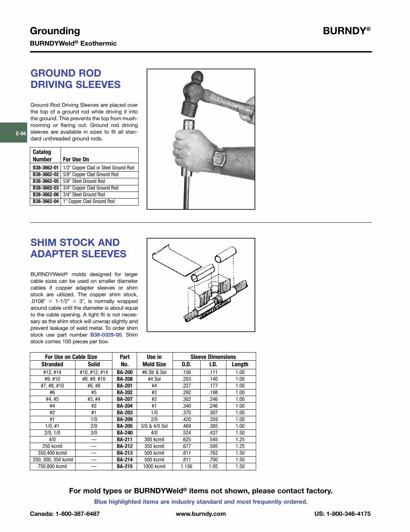
Grounding BURNDY®
BURNDYWeld® Exothermic
Canada: 1-800-387-6487 www.burndy.com US: 1-800-346-4175
Blue highlighted items are industry standard and most frequently ordered.
E-94
GROUND ROD DRIVING SLEEVES
Ground Rod Driving Sleeves are placed overthe top of a ground rod while driving it intothe ground. This prevents the top from mush-rooming or flaring out. Ground rod drivingsleeves are available in sizes to fit all stan-dard unthreaded ground rods.
CatalogNumber For Use OnB38-3662-01 1/2� Copper Clad or Steel Ground RodB38-3662-02 5/8� Copper Clad Ground RodB38-3662-05 5/8� Steel Ground RodB38-3662-03 3/4� Copper Clad Ground RodB38-3662-06 3/4� Steel Ground RodB38-3662-04 1� Copper Clad Ground Rod
For Use on Cable Size Part Use in Sleeve DimensionsStranded Solid No. Mold Size O.D. I.D. Length#12, #14 #10, #12, #14 BA-200 #6 Str & Sol .156 .111 1.00#9. #10 #8. #9. #10 BA-208 #4 Sol .203 .140 1.00
#7, #8, #10 #6, #8 BA-201 #4 .227 .177 1.00#6 #5 BA-202 #2 .292 .198 1.00
#4, #5 #3, #4 BA-207 #2 .302 .246 1.00#4 #2 BA-204 #1 .340 .246 1.00#2 #1 BA-203 1/0 .370 .307 1.00#1 1/0 BA-209 2/0 .420 .359 1.00
1/0, #1 2/0 BA-205 3/0 & 4/0 Sol .469 .385 1.002/0, 1/0 3/0 BA-240 4/0 .524 .437 1.50
4/0 — BA-211 300 kcmil .625 .545 1.25250 kcmil — BA-212 350 kcmil .677 .595 1.25
350,400 kcmil — BA-213 500 kcmil .811 .762 1.50250, 300, 350 kcmil — BA-214 500 kcmil .811 .700 1.50
750,800 kcmil — BA-215 1000 kcmil 1.156 1.05 1.50
SHIM STOCK ANDADAPTER SLEEVES
BURNDYWeld® molds designed for largercable sizes can be used on smaller diametercables if copper adapter sleeves or shimstock are utilized. The copper shim stock,.0108� � 1-1/2� � 3�, is normally wrappedaround cable until the diameter is about equalto the cable opening. A tight fit is not neces-sary as the shim stock will unwrap slightly andprevent leakage of weld metal. To order shimstock use part number B38-0329-00. Shimstock comes 100 pieces per box.
For mold types or BURNDYWeld® items not shown, please contact factory.

BURNDY® GroundingBURNDYWeld® Exothermic
US: 1-800-346-4175 www.burndy.com Canada: 1-800-387-6487
Blue highlighted items are industry standard and most frequently ordered.
E-95
PROBLEM PROBABLE CAUSE CORRECTION TO MAKE
Insufficient metal to Worn mold resulting in Replace mold. If only worn around conductor opening, make weld. leaking weld metal. use duct seal around conductor. Do not get duct seal
into mold cavity.
Wrong size cartridge for mold. Check ID plate for mold and compare with number on bottom of cartridge.
Too much spillage when Carefully open lid while holding over crucible and dump.dumping powder.
Wrong mold for conductor Replace with correct mold. In some applications, shim being used. stock or adapter sleeves can be used to enlarge cable
to fit mold.
Mold does not close tightly Handle clamps not properly adjusted. Remove cotter pin between the handles of the mold and causing weld metal to leak out. adjust handle tension by backing out the eye bolt.
Dirt or slag stuck in parting Clean mold thoroughly between connections.line of mold.
Bent or out-of-round cable. Straighten or cut out bad section of cable.
Handle clamps will not lock Handle clamps not properly adjusted. Remove cotter pin between the handles of the mold and closed. adjust handle tension by backing out the eye bolt.
Excessively high weld, bubbly or Moisture in mold. Pre-heat mold to above 220° F with a propane torch, gassy appearance, poor weld. or ignite a sacrificial shot in mold with pieces of
scrap conductor in it. If it is a horizontally split mold, shoot 3/4 of the recommended cartridge to make sure you do not lock up mold.
Oil, grease, moisture or foreign Pre-heat conductors with propane torch then use a clean material on conductors. wire brush on conductor to remove any residue left on
conductors. If welding to cast iron or steel surface, weld area must be cleaned down to bright metal.
Duct seal in weld cavity. Take special precautions to keep duct seal out of weld cavity.
Weld powder has gotten wet. Replace with fresh, dry weld powder.
Weld metal blows out top of mold. Mold worn or chipped around disc Replace mold.seal allowing powder to leak into mold cavity.
Forgot to use steel disc or did not Make sure disc is seated at bottom of crucibleseat it properly at bottom of crucible. before pouring the powder into crucible.
TROUBLE SHOOTING TIPS

Grounding BURNDY®
BURNDYWeld® Exothermic
Canada: 1-800-387-6487 www.burndy.com US: 1-800-346-4175
Blue highlighted items are industry standard and most frequently ordered.
E-96
TROUBLE SHOOTING TIPS(Continued)
PROBLEM PROBABLE CAUSE CORRECTION TO MAKE
Cannot ignite powder. Insufficient starting powder Place at least half of starting powder in ignition pocket of in ignition pocket on mold lid. mold lid. Use all starting powder for each connection.
Flint ignitor not shooting Clean flint ignitor according to directions on box or replace enough spark. flint ignitor.
Starting powder lumped together. Break up starting powder on lid with edge of powder tube.
Starting powder has gotten wet. Remove shot from mold and replace with a dry cartridge.
Mold wearing out too fast. Improper cleaning of mold. Use mold cleaner, soft natural bristle brush or clean rag to clean mold between shots. Do not use wire brush or screwdriver on molds.
Bent or out of round cable causes Use caution when closing mold. Do not force mold shut chipping and premature wear of around bent, twisted or out of round conductors.the mold.
Poor weld to ground rod. Weight of mold not supported Use locking pliers on ground rod under mold to support during reaction causing mold to the weight of the mold during the reaction.slip when cable melts.
Moisture or contaminant on Pre-heat conductors with propane torch then use a cable or ground rod. clean wire brush on conductors to remove any residue
left on conductors.
Weld will not stick to steel surface. Improperly cleaned area on steel. An area larger than the weld area should be cleaned downto bright clean metal.
Moisture or contaminant on cable Pre-heat conductors with propane torch then use a or ground rod. clean wire brush on conductors to remove any residue
left on conductors.
Cable is improperly positioned in Position cable in mold in accordance with directions for mold, blocking the flow of weld metal. mold. If directions are not available, position top of cable
in the center of where the liquid weld metal hits the steel.
Weld will not stick to cast iron All of the causes listed undersurface. welding to steel surface also
apply to this section.
Not using CI (Cast Iron) powder. Specify “CI” behind cartridge when ordering powder (i.e., 25 CI).
Cable pulls out of mold when Cables are either twisted or Use B38-0330-00 cable clamp or other method to remove it is fired. under tension. tension. Cut out severely twisted cable.