building rural roads - international labour · pdf filewith extensive experience from...
TRANSCRIPT


BUILDING RURAL ROADS

Copyright © International Labour Organization 2008
First published 2008
Publications of the International Labour Office enjoy copyright under Protocol 2 of the Universal
Copyright Convention. Nevertheless, short excerpts from them may be reproduced without authorization,
on condition that the source is indicated. For rights of reproduction or translation, application should be
made to ILO Publications (Rights and Permissions), International Labour Office, CH-1211 Geneva 22,
Switzerland, or by email: [email protected]. The International Labour Office welcomes such applications.
Libraries, institutions and other users registered with reproduction rights organizations may make
copies in accordance with the licences issued to them for this purpose. Visit www.ifrro.org to find the
reproduction rights organization in your country.
Johannessen, Bjørn
Building rural roads / Bjørn Johannessen. - Bangkok: ILO, 2008
466 p.
ISBN: 9789221209775; 9789221209782 (web pdf)
International Labour Organization; ILO Regional Office for Asia and the Pacific; ILO ASIST Asia Pacific
road construction / rural public works / labour intensive employment / rural employment / poverty alleviation
10.05.6
ILO Cataloguing in Publication Data
The designations employed in ILO publications, which are in conformity with United Nations practice,
and the presentation of material therein do not imply the expression of any opinion whatsoever on the
part of the International Labour Office concerning the legal status of any country, area or territory or of its
authorities, or concerning the delimitation of its frontiers.
The responsibility for opinions expressed in signed articles, studies and other contributions rests solely
with their authors, and publication does not constitute an endorsement by the International Labour Office
of the opinions expressed in them.
Reference to names of firms and commercial products and processes does not imply their endorsement
by the International Labour Office, and any failure to mention a particular firm, commercial product or
process is not a sign of disapproval.
ILO publications can be obtained through major booksellers or ILO local offices in many countries, or direct
from ILO Publications, International Labour Office, CH-1211 Geneva 22, Switzerland. Catalogues or lists of
new publications are available free of charge from the above address, or by email: [email protected]
Visit our website: www.ilo.org/publns and www.ilo.org/eiip
Layout by Sync Design Co. Ltd. Thailand
Printed in Thailand
CTP 173

REFERENCES
ACKNOWLEDGEMENTS ............................................................................................................7
INTRODUCTION ........................................................................................................................8
CHAPTER 1 PLANNING AND PREPARATION OF WORKS ................................................9
1.1 Planning Framework .......................................................................10
1.2 Key Features of a Plan ....................................................................18
1.3 Road Selection ..............................................................................19
1.4 Selection Criteria ...........................................................................22
1.5 Design Standards ...........................................................................28
1.6 Technology Choice .........................................................................36
1.7 Road Inventories ............................................................................38
1.8 Planning and Estimating Works .......................................................42
1.9 Design Process ..............................................................................43
1.10 Road Alignments ............................................................................45
1.11 Quantity Surveying .........................................................................49
1.12 Time Management Planning ............................................................51
1.13 Cost Estimating .............................................................................60
1.14 Tendering Stage .............................................................................70
1.15 Works Implementation ....................................................................72
CHAPTER 2 SURVEYING AND SETTING OUT ...............................................................75
2.1 Selecting the Road Alignment .........................................................76
2.2 Tools for Surveying and Setting Out .................................................81
2.3 Horizontal Alignment ..................................................................... 90
2.4 Vertical Alignment ..........................................................................98
2.5 Setting Out Cross Sections ............................................................105
CHAPTER 3 TOOLS AND EQUIPMENT .......................................................................115
3.1 Importance of Tools and Equipment ...............................................116
3.2 Quality of Tools ............................................................................117
3.3 Characteristics of Suitable Hand Tools ...........................................118
3.4 Maintenance and Repair of Hand Tools ..........................................130
3.5 Construction Equipment ..............................................................134
3.6 Maintenance of Equipment ...........................................................142
CHAPTER 4 CLEARING ............................................................................................145
4.1 Site Clearing ................................................................................146
4.2 Bush Clearing ..............................................................................148
4.3 Tree and Stump Removal ..............................................................149
4.4 Grubbing .....................................................................................151
4.5 Boulder Removal ..........................................................................152

CHAPTER 5 EARTHWORKS ......................................................................................155
5.1 Definition ...................................................................................156
5.2 Construction Principles .................................................................159
5.3 Calculating Volumes .....................................................................165
5.4 Organising the Excavation Works ...................................................169
5.5 Embankment Construction ............................................................172
5.6 Side Drain and Camber Construction .............................................180
5.7 Transporting Materials ..................................................................184
5.8 Rock Excavation ...........................................................................187
5.9 Slope Stabilisation .......................................................................190
CHAPTER 6 GABION WORKS ....................................................................................199
6.1 Introduction ................................................................................ 200
6.2 Size and Specifications .................................................................202
6.3 Assembling the Cages ................................................................. 204
6.4 Common Layouts for Structures Using Gabions .............................. 208
6.5 Drainage Structures ......................................................................210
6.6 Bank Protection ...........................................................................211
CHAPTER 7 DRAINAGE ............................................................................................213
7.1 Overview .....................................................................................214
7.2 Road Surface Drainage .................................................................217
7.3 Side Drains ..................................................................................226
7.4 Mitre Drains .................................................................................230
7.5 Scour Checks ............................................................................. 233
7.6 Catch-water Drains .......................................................................235
7.7 Culverts ......................................................................................237
7.8 Drifts ..........................................................................................237
7.9 Vented Fords ...............................................................................244
CHAPTER 8 CULVERTS ............................................................................................249
8.1 Introduction .................................................................................250
8.2 Culvert Location ...........................................................................255
8.3 Setting Out ..................................................................................256
8.4 Setting Out Procedures .................................................................257
8.5 Construction Operations ...............................................................267
8.6 Constructing Headwalls, Wing Walls and Aprons .............................270
8.7 Culvert Approaches ......................................................................275
8.8 Concrete Pipe Manufacture ...........................................................275
8.9 Corrugated Steel Pipes .................................................................280

CHAPTER 9 PAVEMENT ............................................................................................281
9.1 Function and Composition of Road Pavements ................................282
9.2 Pavement Design .........................................................................285
9.3 Pavement Types ...........................................................................293
9.4 Earth Roads ............................................................................... 294
9.5 Gravel Roads .............................................................................. 298
9.6 Soil Mixing ..................................................................................315
9.7 Chemically Stabilized Soils ............................................................317
9.8 Macadam Type Pavements ............................................................318
9.9 Bituminous Pavements .................................................................321
9.10 Surface Dressings ........................................................................327
9.11 Otta Seals ...................................................................................331
9.12 Stone Pavements ........................................................................ 336
9.13 Concrete Surfaces ........................................................................341
CHAPTER 10 SOIL MECHANICS ................................................................................ 345
10.1 Introduction ................................................................................ 346
10.2 Definitions ...................................................................................347
10.3 Distinguishing Soils ......................................................................351
10.4 Simple Field Tests ....................................................................... 353
10.5 Soil Sampling ..............................................................................357
10.6 Laboratory Testing ....................................................................... 360
10.7 Applying Compaction to Various Soil Types .....................................370
CHAPTER 11 COMPACTION ........................................................................................373
11.1 Purpose ......................................................................................374
11.2 Fundamentals of Compaction ........................................................375
11.3 Compaction Methods ................................................................... 380
11.4 Compaction Procedures ............................................................... 384
11.5 Quality Standards ........................................................................ 385
CHAPTER 12 CONCRETE WORKS ...............................................................................387
12.1 Basic Features ............................................................................ 388
12.2 Materials and Storage ...................................................................391
12.3 Proportion of Components ............................................................393
12.4 Water to Cement Ratio ..................................................................394
12.5 Mixing Concrete ...........................................................................395
12.6 Formwork ....................................................................................398
12.7 Transport of Concrete ...................................................................401
12.8 Pouring Concrete ........................................................................ 403
12.9 Curing ........................................................................................ 405
12.10 Quality Testing .............................................................................407

CHAPTER 13 SETTING UP AND ADMINISTERING A SITE ............................................ 409
13.1 Introduction .................................................................................410
13.2 Setting Up a Camp .......................................................................410
13.3 Quarries and Borrow Pits ..............................................................413
13.4 Administrative and Financial Routines ............................................414
13.5 Site Stores .................................................................................. 417
13.6 Personnel Management ................................................................421
13.7 Site Meetings ..............................................................................425
13.8 Work Safety .................................................................................425
CHAPTER 14 WORK ORGANISATION ..........................................................................427
14.1 Introduction .................................................................................428
14.2 Work Programming ...................................................................... 430
14.3 Incentives ................................................................................... 433
14.4 Setting Task Rates ...................................................................... 438
14.5 Managing the Workforce .............................................................. 440
14.6 Organising Subcontractors ........................................................... 443
14.7 Traffic on Site ............................................................................. 444
CHAPTER 15 REPORTING AND CONTROL .................................................................. 445
15.1 Overview .................................................................................... 446
15.2 Monitoring Works .........................................................................449
15.3 Drawings and Work Specifications .................................................452
15.4 Inspection of Works ..................................................................... 453
15.5 Quality Control ............................................................................ 454
15.6 Quality Assurance ........................................................................456
15.7 Measurement of Works ................................................................ 458
15.8 Records and Reports ................................................................... 458
REFERENCES ....... ......... ...................................................................................................... 464

ACKNOWLEDGEMENTS
For the past 30 years the ILO has been involved in capacity development and training for the effective provision of rural infrastructure. Through ASIST in Asia and the Pacific, the ILO promotes the use of local resource based technology as a means of improving the capacity of local government institutions to effectively deliver rural infrastructure services in developing countries. This manual has been produced as part of this programme.
The use of local resource based technology has been established in a number of countries, and is efficiently being applied in a large number of rural road development programmes. Its success, in terms of emphasising the use of locally available resources such as labour, tools and light equipment, combined with good workmanship and high quality standards, has given this technology its due recognition. The active support and promotion of such technology is not limited to national governments but also includes a number of international organisations and international development banks.
Although the principal approach remains the same, the exact definition of the technology varies from one country to another, depending on the prevailing site conditions, design standards, local building practices and the actual availability of local resources. For this reason, the technology differs quite significantly from one programme to another. Despite this, there are certain best practices that are commonly applied across the range.
This manual attempts to present a set of technical solutions and work methods commonly applied in a number of countries where the use of local resources is given serious consideration when building rural roads. It describes a set of work methods and procedures which have demonstrated in practice that they are effective both in terms of cost and quality. To achieve this, the development of this document has drawn on the best practices that have been identified in several rural road building programmes. In addition, it is based on an in-depth review of existing literature from such programmes.
As part of the acknowledgements, it is therefore important to recognise the importance of all the innovative work that has taken place in the various completed and ongoing rural road development programmes. This includes the manuals and training material produced for these programmes. It is only with this work as a basis, that it has been possible to present the technology in a more generic version.
The contents of this manual have been developed with valuable inputs from engineers with extensive experience from managing rural road construction works in a number of countries. In this respect, particular acknowledgement is hereby given to the technical inputs provided by Pen Sonath, Pisit Tusanasorn and Geoff Edmonds.
00
7B
UILD
ING
RU
RA
L RO
AD
S

INTRODUCTION
Rural roads are the last link of the transport network, however, they often form the most important connection in terms of providing access for the rural population. The permanent or seasonal absence of road access is a constraining factor in terms of providing rural communities with essential services such as education, primary health care, water supply, local markets as well as economic opportunities. The availability of such services and opportunities are difficult to sustain without a good quality and well-maintained rural road network, which provides regular and efficient transport access throughout the year.
Building good quality rural roads is a particular skill in itself, requiring proper p l a nn ing , e xper ienc ed supervision, good workmanship and the selection of the correct technology and work methods.
Rural roads provide a critical link in a road transport network, facilitating access to and development of the rural areas. While these roads form the
majority portion of the road network, they often carry low volumes of traffic. Despite this, their design and construction need to cater for the common type of vehicle loads and allow access throughout the year and in all kinds of weather conditions.
These features place specific challenges to the road agencies in charge. On the one hand, there is a need to find good engineering solutions addressing the functional requirements relating to maintaining all-weather access. On the other hand, due to the size and extensive distribution of rural roads, road agencies are under pressure to find low cost solutions that allow authorities to build and maintain an extensive network of roads.
The purpose of this manual is to provide technical staff ranging from site supervisors to engineers with a technical reference which in detail explains and describes commonly used work methods and best practices for constructing rural roads.
It describes all phases of works management from the initial stages of identification and preliminary design through technical planning, work organisation, works implementation methods and procedures, site administration to reporting and control. The topics cover the skills required from technical staff responsible for carrying out rural road construction and rehabilitation works.
BU
ILDIN
G R
UR
AL R
OA
DS
00
8

P L A N N I N G A N D
P R E P A R A T I O N O F W O R K S
CHAPTER 1
P1.1 Planning Framework
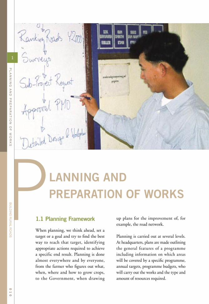
When planning, we think ahead, set a target or a goal and try to find the best way to reach that target, identifying appropriate actions required to achieve a specific end result. Planning is done almost everywhere and by everyone, from the farmer who figures out what, when, where and how to grow crops, to the Government, when drawing
LANNING ANDPREPARATION OF WORKS
up plans for the improvement of, for example, the road network.
Planning is carried out at several levels. At headquarters, plans are made outlining the general features of a programme including information on which areas will be covered by a specific programme, annual targets, programme budgets, who will carry out the works and the type and amount of resources required.
1
PL
AN
NIN
G A
ND
PR
EP
AR
AT
ION
OF
WO
RK
S
BU
ILDIN
G R
UR
AL R
OA
DS
01
0

At the other end, at site level, plans are more specific and describe in detail how work is distributed over the next few weeks or months and what progress is to be achieved utilising specif ic resources such as a particular group of people and equipment carrying out a series of related work activities.
There are many different types of plans and many different names for them, but usually they are called after the level at which they are to be used and/or their duration, e.g. overall programme plans, site plans, monthly work plans and weekly/daily work plans.
National PlansThe various types and levels of planning carried out in the road sector are normally organised within a framework of general policy documents, guidelines and procedure s . Physica l work s planning start with comprehensive plans covering the nation as a whole. In nat iona l deve lopment plans , governments specify their intentions in each sector by defining functional goals as well as formulating strategies describing how to reach such targets. Targets for the road sector are often related to levels of mobility and access. National targets for rural road networks are commonly formulated as the extent to which all-weather access is provided to communities of a certain size or providing all-weather roads within a defined proximity of where people live. Goals and targets for each sector can be very ambitious and may take several years to reach.
In order to be able to measure progress
and to what degree the government is successful in moving towards its ultimate goals, development plans will include a time schedule during which specific targets or milestones are to be reached. As part of this exercise, the authorities may establish specia l development programmes to increase the speed at which the goals can be reached. Centrally based technical agencies, such as planning ministries and technical departments play an important role in terms of scheduling and estimating the overall resources required to reach intermittent milestones in a programme.
Transport Sector PlansIn line with the contents of national deve lopment plans , each sec tor commonly prepares a set of long-term planning documents, often referred to as sector studies, implementation strategies or strategic plans. The sector plans relating to transport usually contain an analysis of the current situation in terms of existing infrastructure assets, current transport pat terns , on-going development programmes, levels of recurrent budgets and improvement budgets. On this basis, projections are made re l a t ing to f utu re dema nd s for development, funding needs and possible funding sources, and suggesting
1
PL
AN
NIN
G A
ND
PR
EP
AR
AT
ION
OF
WO
RK
S
BU
ILDIN
G R
UR
AL R
OA
DS
01
1

a strategy for reaching the formulated targets. Transport sector studies present the government's long-term strategies and plans for the sector, commonly with a time span of 5 to 10 years. Although the government will make every effort to achieve the goals contained in these sector plans, it is important to note that these plans and strategies are not directly linked to any specific budget allocations. The extent to which these plans are realised depends on the annual budgeting and work programmes approved by the political bodies.
Annual Programmes and BudgetsAnnual budgets are the f irst set of concrete plans for which specif ic resources are dedicated. The annual work programmes and budgets for the road sector form an integral part of the annual programme and budget prepared by the central government for all sectors. The planning and preparatory work behind the annual work programmes normally commence a year in advance of its announcement, thereby securing the inputs of a l l stakeholders and also allowing for the assembly of the necessary data to support the cost projections in the budget.
Traditionally, this exercise was very much an undertaking by headquarters, however, with the decentralisation of government in recent years this exercise has become an integral part of local planning processes. In addition to the central government budget procedure, local government institutions carry out a simi la r exercise of annua l programming and budgeting. As rural roads are often under the jurisdiction of
local government administrations, the local technical agency in charge of rural road works needs to be fully involved in this annual planning process.
Local PlansIn addit ion to the annua l work programmes, rural road works agencies will need to develop long-term plans for the development and maintenance of the road network under their respective jurisdictions. Annual budgets do not meet the requirements of all requests for improvements, so a long-term strategy describing when and where developments can take place will need to be developed based on the priorities of local political bodies. Some development projects require a construction period longer than the standard budget year. Equally, the timing and contents of maintenance works wil l vary from one year to another. For these reasons, it is useful for the road agency to carry out periodic plans covering a period of 3 to 5 years.
Project PlansProject plans commonly relate to specific development projects, normally involving the construction or improvement of one particular road section. Project plans provide details on the basis of which approval and funding decisions are made. Equally, these plans form the basis for the detailed engineering plans and in the next step the contract doc u ment s u s e d du r i n g work s implementation.
Detailed PlansDe t a i l e d p l a n s a r e t he work i n g documents which the technical staff
1
PL
AN
NIN
G A
ND
PR
EP
AR
AT
ION
OF
WO
RK
S
BU
ILDIN
G R
UR
AL R
OA
DS
01
2

refer to in relation to the scheduling of individual work activities, supply of equipment and materials and hiring of staff and labour. Detailed plans are prepared for various time horizons, ranging from the entire duration of the project, to monthly, weekly and daily work plans. The main purpose of the detailed plans is to secure proper management of all resources used as inputs to produce the planned outputs. These plans are normally combined with a comprehensive repor t ing and monitoring system, a l lowing management to compare ac tua l achievements with the planned targets.
Maintenance PlansPlanning is often associated with new development initiatives, however, a substantial part of planning carried out by any road works agency relates to the optimal and most effective ways of utilising available resources to maintain already existing infrastructure assets. The preparation of effective road
maintenance plans is by far the most important part of the planning activities carried out by the authorities in charge of the road network. As mentioned above, maintenance planning needs to be carried out on a periodic basis and well as on an annual basis.
An important feature of all infrastructure works planning is the need to make adequate provisions for the upkeep of the existing assets and installations which have been developed in the past. Although this issue is often neglected, it would seem obvious that the first priority in any works programme would be to protect already existing infrastructure investments, before spending money on building new developments. For this reason, government budgets normally consists of a recurrent budget to deal with the upkeep of already existing installations and an investment budget for the purpose of improving the level of services. When building new roads or upgrading existing roads to higher standards, funds are normally sourced from investment budgets.
Legal FrameworkMost rural road works form part of the public services provided by the government. The investments made in the development and maintenance of road a sset s a re norma l ly made from government funding, and as a consequence the created (and maintained) assets are regarded as the property of the government. Ownership issues such as who is in charge of the operation of these infrastructure assets are defined in legal provisions, often consisting of national legislation combined with
1
PL
AN
NIN
G A
ND
PR
EP
AR
AT
ION
OF
WO
RK
S
BU
ILDIN
G R
UR
AL R
OA
DS
01
3

specific regulations following the general provisions in national laws.
Who is in charge of operating and maintaining different segments of the public road network is normally defined in national legislation such as a Road Act. Equally, if the authority for rural roads has been delegated to local government, this decision is often ref lected in the laws and provisions defining the role and responsibilities of local government authorities.
Regulating BodiesThe implementation of a road works programme is regulated by a series of procedures and guidelines. These procedures commonly cover subjects such as the planning process, programming and budget ing, procurement and contracting arrangements, technical standards and works specif ications, and finally monitoring and reporting. There may also be regulations relating to social and environmental aspects which need to be observed in relation to civil works projects. In addition, the institution providing the funding may insist on certain conditions under which the resources are utilised.
Regulating bodies may consist of both government organisations as well as private sector organisations. Any public works programme will be prepared following the general planning procedures pertaining to the source of the funds and the specific sector under which the programme of works belong. Development plans are commonly produced at national level as well as by local government
authorities (i.e. district development plans). Plans at the various levels in the government hierarchy, not only need to adopt certain standard formats, they also have specific approval procedures thereby incorporating basic democratic principles and securing a certain process of consultation with the population who will be affected by the proposed development initiatives.
Setting realistic goals and targets for any type of public services requires good knowledge relating to the costs and amount of resources required to reach these goals. For the purpose of consistency and to ensure that all parties are adhering to the same planning and implementation strategies, the national agencies often develop a set of standard work practices, which include items such as standard designs and work arrangements, catering for the various conditions in which the infrastructure services are expected to operate.
Road Classification Planning in the road sector is organised according the divisions of responsibility for the road network. Highways and other roads of national importance are often covered by a national road works agency, while roads providing access to and for local communities is often under the jurisdiction of local government authorit ies. In order to dist inguish between the main components of the public road network, roads are classified in groups according to their purpose, such as main or national roads, provincial, district and basic access roads.
1
PL
AN
NIN
G A
ND
PR
EP
AR
AT
ION
OF
WO
RK
S
BU
ILDIN
G R
UR
AL R
OA
DS
01
4

1
PL
AN
NIN
G A
ND
PR
EP
AR
AT
ION
OF
WO
RK
S
BU
ILDIN
G R
UR
AL R
OA
DS
01
5

The development and maintenance of each of these road classes is normally assigned to dif ferent government agencies. Works related to national roads and highways are commonly assigned to a national road agency or a centrally based works ministry. The provision of provincial and district roads is often part of the responsibilities of local government authorities.
Other roads, such as forest roads, roads to national monuments and roads built for military purposes, are maintained by the respective departments in charge of the activities for which these roads serve. The provision of urban roads and streets is the responsibility of city administrations or municipalities.
All these government authorities may not necessarily have the technical capacity to manage and supervise road works, and for this reason may decide to delegate this management task to an agency which carries the necessary capacity.
Within local government administrations, there would normally be a dedicated technical department in charge of the maintenance and development of the local road network. On the basis of the priorities set by local political bodies and assemblies, the local government road works units prepare periodic plans and annual works programmes, which include plans, detailing (i) how local roads will be maintained and (ii) if additional resources are available, any improvements to the network.
Setting Work StandardsFor each of the road classes in the public road network, the government develops a set of design guidelines. These design guidelines includes general directions on the geometric features of the roads, such as appropriate dimensions of the road cross-section and curvature, surfacing options, drainage solutions, road reserves, etc. These guidelines are normally based on input parameters such as prevailing and expected traffic volumes and terrain conditions.
In addition to the road design standards, most governments issue standard specif ications relating to how civil works should be carried out. Work specifications are essential in the process of securing that the construction works meet genera l ly accepted industry quality standards. Work specifications forms part of the guidelines to be applied when carrying out any civil works relating to public infrastructure. The speci f icat ions a re norma l ly developed by a technical unit in a civil works department or alternatively by a professional society representing technical staff from the respective engineering sectors, (i.e. association of road and bridge engineers).
Other Standard ProceduresAll public expenditure is governed by a comprehensive set of procedures and directives detailing how funds are to be used and accounted for. These procedures include budgeting and accounting procedures as well as detailed regulations on the contracting a rrangements. Most government administrations employ dedicated staff
1
PL
AN
NIN
G A
ND
PR
EP
AR
AT
ION
OF
WO
RK
S
BU
ILDIN
G R
UR
AL R
OA
DS
01
6

to deal with budgeting and accounting, however, these tasks also form an integral part of the responsibilities of the technical staff in charge of civil works activities.
In addition, roads works programmes need to meet a number of social and environmental impact considerations. In order to secure this, the government develops a set of procedures and guidelines to ensure that such consideration are part of the planning process.
Finally, it is worth mentioning that the government provides specif ic regulations on employment conditions and occupational safety and health which need to be observed during works implementation. Equally, the contracting arrangements will normally be integrated into a legal framework, which spells out some of the basic principles of contracting, covering issues such as resolution of conflicts, liability, employers responsibilities, legal status of contracts, etc.
From Plans to ImplementationThe planning process forms the basis for all budgeting and resource scheduling required in civil works projects. Periodic and long-term plans provide estimates for long-term budget projections, while detailed plans are important for the budgeting carried out on an annual and project basis. The detailed plans a lso contain essentia l information which forms the backbone of the civil works contracts issued during works implementation. Data pertaining to the amount and location of work constitutes the most important part of most civil works contracts.
The timely completion of works according to a plan is also a key determinant in measuring progress of works and assessing the efficiency of a civil works programme. In order to obtain an objective picture of the progress in a civil works programme, a comprehensive monitoring system is installed in which the achieved work outputs are measured and compared against the originally planned work schedule.
1
PL
AN
NIN
G A
ND
PR
EP
AR
AT
ION
OF
WO
RK
S
BU
ILDIN
G R
UR
AL R
OA
DS
01
7

1.2 Key Features of a Plan
All plans need to contain certain key information in order to serve the purpose of providing the guidance and targets for which they are intended. When preparing a road development programme, the planning works rely on basic principles applied when carrying out any planning.
For the sake of clarity and in order to remain focussed on the task at hand, it is useful to clearly define the purpose or objective of the plan. Equally, it is essential that the justif ication for carrying out any programmed
activities is clear to all parties involved. As part of the justification, a key issue is to identify the beneficiaries of the project.
A civil works plan defines key outputs the achievement of which justifies the expenditure. The plan will also specify the exact location of the work and when it is planned to commence, its duration and when it is expected to be complete. When preparing budgets, the outputs are often the key data against which the project is appraised and evaluated.
The planned activities are linked to each of the outputs in the plan. In order to achieve a specif ic output, certain activities need to take place in a particular sequence or schedule of events. Some activities are linked to others, requiring the completion of
PLANNING consists of setting specific targets and goals and specifying in detail the necessary resources and actions to reach those targets.
1
PL
AN
NIN
G A
ND
PR
EP
AR
AT
ION
OF
WO
RK
S
BU
ILDIN
G R
UR
AL R
OA
DS
01
8

certain outputs before the next work activities can commence.
The sequence in which the activities need to take place can be presented in f low charts as part of the time management planning process. With good estimates of the production rates and measured quantities, it is then possible to establish the exact duration of each work activity. A full work programme with start dates, milestones and completion dates can then be established.
The inputs to a works project or programme consist of all the resources required in order to create the defined outputs. In civil works, these are essentially labour, materials, tools and equipment. Tools and materials are mostly consumable items which when estimated to the correct quantity will be used in their entirety for the purpose of the individual project. Labour and equipment are time bound inputs and their usage and costs need to be estimated on the basis of a unit rate and for how long they will be required.
Based on the consumption of materials and usage of equipment and labour, it is possible to estimate the cost of each of the individual activities. Some cost items are directly linked to the amount of quantity of outputs produced while other cost items are linked to the time duration during which a certain activity will take place. The total cost of all envisaged activities will constitute the project budget estimate.
1.3 Road Selection
The ProcessRoads to be constructed, improved or maintained under a particular prog ra mme a re not s e le c ted in an arbitrary manner. While each programme will have its own tailor-made identif ication and selection procedures, the process will in most cases consist of a number of distinct stages:
Initial IdentificationThe initial identification step is the preparation of a l ist of proposed roads to be improved or maintained. This initial list will, in most cases, be prepared with the involvement of local communities or their political representation. Generally, the proposed roads must meet pre-determined criteria set by the programme management in collaboration with the planning and funding authorities.
The proposed roads that meet the programme criteria are then forwarded through the local authorities (i.e. district and provincial development committees) for further discussion in terms of priorities and coordination
1
PL
AN
NIN
G A
ND
PR
EP
AR
AT
ION
OF
WO
RK
S
BU
ILDIN
G R
UR
AL R
OA
DS
01
9

with other local development activities. Afterwards, the list with the proposed roads is forwarded to the implementing agency for screening.
ScreeningThe technical agency usually carries out the screening of identified roads in order to disqualify those projects that do not meet certain criteria, are not technically or economically feasible, or are not likely to have the expected impact. These assessments are usually carried out on the basis of rough estimates of costs and benefits of the proposed works, such as the size of population and number of communities served. The screening may also include an initial assessment of social and environmental impacts.
Ideally, the technical agency will only provide information as regards to costs and feasibility of a certain project, and on this basis determine whether the project meets established selection criteria. The f inal decision whether to still appraise a project in detail
should be taken by the appropriate development committee.
AppraisalAppraisal is a more detailed assessment for supporting an investment in a certain road. Often, a cost benef it analysis is carried out as part of an appraisal. This implies that construction costs need to be estimated and socio-economic data assembled (population densities, agricultural potential, traffic volumes, etc.).
RankingA programme may not be able to absorb all selected roads which have passed the screening and appraisal stages. In addition, some roads will be of higher importance than others for various reasons. An overall ranking of the selected roads, on the basis of overall weights of some important evaluation factors, will be necessary in order to decide which roads should receive priority and in what order. The criteria used for ranking may be simple, e.g. the road with the lowest cost per
1
PL
AN
NIN
G A
ND
PR
EP
AR
AT
ION
OF
WO
RK
S
BU
ILDIN
G R
UR
AL R
OA
DS
02
0

head of population served could be improved first. At this stage other social criteria may also be introduced.
ApprovalAs a f inal step, the roads selected according to this process will need to be approved by the relevant authorities. The approval may need to come from provincial or central authorities, and in some cases from a funding agency. The technical line departments or planning authorities may need to be consulted to ensure that the individual projects fit into larger comprehensive plans to avoid any duplication of efforts and to make sure that all individual projects are contributing to overall development objectives in a coordinated manner. No work can start before such approval has been given and funding has been secured.
This process of identif ication and selection of sub-projects in an overall works programme is a time consuming
process. From initial identification to f inally securing formal approval of the plan and receiving the budgeted funds may take one to two years. For this reason, it is common practice to establish a schedule for this process in which specific deadlines are set for the completion of each of the main events described above.
Equally, this process will require a team of technical staff who can carry out the identification, costing and technical screening. Finally, the political bodies in charge of taking the final decisions will need to be assembled to secure the necessary approvals before the work programme is official.
When all the approvals have been secured, the technical authorities will commence the detailed planning and the preparation of detailed designs and estimates for each of the individual projects, and f inally commence the preparation of contract documents.
1
PL
AN
NIN
G A
ND
PR
EP
AR
AT
ION
OF
WO
RK
S
BU
ILDIN
G R
UR
AL R
OA
DS
02
1

1.4 Selection Criteria
As in all infrastructure works, there are essentially three main criteria which needs to be considered when proposing a new rural road development project:
(i) technical feasibility,(ii) economic justification and (iii) social considerations.
Technical FeasibilityThe technical feasibility starts out with a rapid assessment of whether it is possible to carry out the project from a technical point of view. Some aspects of rural road construction may not be obvious to everybody involved in the decision making process. It is therefore useful to secure some guidance at an early stage from technical staff to ensure that a particular proposal is technically feasible.By doing so, it is possible to rule out impracticable projects such as proposals with very large bridge crossings, alignments through very diff icult terrain or through areas where land cannot be made available for road building purposes. Other important technical considerations are:
• The road should connect to a well-maintained road, thereby adding on to the existing functional road network in the area.
• When considering a new project it is important to make a rapid assessment of the future road alignment, investigating the need for expensive structures such as bridges, heavy earth works through rocky and steep
terrain, difficult soil types, etc.• Building materials such as gravel,
aggregate and water should be available at a reasonable distance from the work sites.
• A local authority to take charge of future maintenance requirements.
• There should be sufficient funds available to provide periodic and routine maintenance.
• If the use of labour-based work methods is a prerequisite (e.g. on Food for Work programmes or other rura l employment generation schemes), then a minimum of 100 persons should be available and interested in working for the project under the terms and conditions offered.
Economic JustificationVarious investment models are available to carry out the economic analysis. The benefits normally considered in economic evaluations are:
• direct savings in the cost of operating vehicles,
1
PL
AN
NIN
G A
ND
PR
EP
AR
AT
ION
OF
WO
RK
S
BU
ILDIN
G R
UR
AL R
OA
DS
02
2

• time savings by travellers and freight,
• economies in road maintenance costs,
• reductions in road accidents (although these often increase on improved roads), and
• wider effects on the economic development of the region.
Investment models are available to estimate the total transport costs associated with different road designs including vehicle operating costs, maintenance costs and renewal costs under a variety of traffic, climatic and maintenance conditions.
A choice of higher design standards may st i l l achieve the established thresholds of rate of return, however, not necessarily giving the best value for money. In a number of developing countries, finance is usually scarce and it is therefore equally important to utilise minimum effective designs and thereby releasing savings to be used for
other road works activities.
Rural roads, however, represent the grass roots of the road network, feeding traffic into the secondary and primary roads and opening access to the rural areas. Rural roads often have low traffic volumes and are generally constructed using simple designs which essentially secure all-year round access. For these roads, the economic justification for the investment rests mainly on the expected impact on social and agricultural development. Both these outputs are time related and may have a large element of uncertainty.
The extent to which the local economy adjacent to the proposed road will benefit from the investment depends on a series of economic parameters such as availability of land, irrigation facilities, pricing mechanisms on farm products, labour and transportation costs and several others. To forecast an increase in agricultural production
1
PL
AN
NIN
G A
ND
PR
EP
AR
AT
ION
OF
WO
RK
S
BU
ILDIN
G R
UR
AL R
OA
DS
02
3

1
PL
AN
NIN
G A
ND
PR
EP
AR
AT
ION
OF
WO
RK
S
BU
ILDIN
G R
UR
AL R
OA
DS
02
4
and producer benefits can be a complex and difficult task. The effect of rural road improvement works on the local economy is equally difficult to predict and virtually impossible to model, and any assessment made will have a high element of uncertainty and rely on a series of assumptions.
The cost of detailed socio-economic evaluation using sophisticated modelling techniques ahs to be put into the context of the selection of low cost, low volume roads. Fortunately in recent years simple techniques have been developed and have won general acceptance.In terms of maintenance economics, there are, however, clear principles which can be applied. A basic rule for any road works programme is to protect previous investments and therefore to allocate available funds according in the following order:
(i) First, provide regular and timely maintenance to the sections of the network which are in a good and maintainable condition. "Good" condition is when the road section requires a minimum of routine maintenance, which c a n b e prov ide d t h rou g h a r r a ngement s such a s t he lengthman system.
(ii) S e c o n d l y , p r o v i d e s p o t improvements and periodic m a i n t e n a n c e t o h a l t t h e deterioration of road sections in fair condition, thereby upgrading t h e m t o a m a i n t a i n a b l e condition and thus keeping the entire road passable.
(iii) Thirdly, rehabilitate existing
road sections which have fallen into total disrepair.
(iv) Once the three activities above have been secured, including regular maintenance for newly upgraded road sections, one should be looking into new construction and expanding the road network. Once again, new projects should only be accepted when suff icient maintenance resources are available or can be secured for the new roads being added to the network.
Social CriteriaInvestments related to the development and improvement of major highways and trunk roads are justified on the basis of optimising the economics of transport. By providing roads with higher capacity, the overall transport costs can be reduced. Rural roads often have low traff ic volumes and investments in their development can be hard to justify on a purely economic basis. Instead, social benefits can also be included on the basis of facilitating the provision of basic access to social services. The following are amongst the social criteria that may be used for ranking rural road rehabilitation projects:
• The area influenced by the road. The larger the area of influence, the higher the priority. The correct determination of the area served is important but can be difficult to identify. Watersheds, rivers or the proximity to adjacent roads generally dictates the limits to this area.
1
PL
AN
NIN
G A
ND
PR
EP
AR
AT
ION
OF
WO
RK
S
BU
ILDIN
G R
UR
AL R
OA
DS
02
5

• The inhabitants served. The greater the number of inhabitants to be served, the higher the priority.
• Present condition of the road. Communities without any access should be given high priority. The better the existing access, the lower the priority.
• The availability of all weather access. Communities without access during some parts of the year should be given higher priority.
• Present transportation costs per km. Road transport costs are related to the road condition. The higher the present costs, the more these costs will decrease through road improvements.
• The area of cultivable land within the area of influence. A rural road programme should benef it a s many farmers as possible. Roads leading to fewer
farms and households should be given lower priority.
• Increased area of cultivable land. By improving access, the inhabitants may be encouraged to cultivate more land within the area of influence of the road.
• T he potent i a l i nc re a s e i n marketable production. Increased production is related to road conditions, because improved access to markets will encourage the inhabitants to produce more goods to sell.
• The availability of socia l and e c o n o m i c s e r v i c e s . M o s t of the soc ia l and economic services (health, education, and agricultural extension services) end where the trafficable road ends and go no further. Improved access can extend these services to isolated communities.
1
PL
AN
NIN
G A
ND
PR
EP
AR
AT
ION
OF
WO
RK
S
BU
ILDIN
G R
UR
AL R
OA
DS
02
6

Integrated Rural Accessibility Planning - IRAP
As opposed to appraising the economic rate of return for investments in improvement of a single road in isolation from the rest of the transport network, IRAP follows an approach in which all transport patterns and transport needs in a given area are assessed before making decisions on road investment priorities. Rather than looking at road improvements from a pure economic perspective in terms of reducing transport costs on one specific road section, IRAP looks at the entire network in an area and prioritises links base on a cost benefit approach, where the benefits are expressed as improvements in access per person.
The planning tools seek to reduce travel time to basic services such as health, education and other public services as well as improve transport of goods and services to and from the rural communities. The planning process starts by mapping existing travel patterns and on this basis tries to identify existing constraints in the transport system. As the process links travel to other public services (and economic activities) the approach provides a multi-sector planning tool, which with very simple methods analyses how the transport needs are linked to other sectors.
The prioritisation of roads is based on a simple cost per person served augmented by a weighting system based on the expressed demand of the local population for access to different types of services such as health, education or markets.
The system is designed to rely on a high degree of community involvement for both data assembly and compilation. It also includes effective procedures for consultation with the future users of the infrastructure as well as providing local government planners with clear guidelines on how to present and justify the final development plan.
The final outcome from this planning process is a comprehensive local transport master plan, which not only lists a series of road improvement projects, but also provides a proper rationale behind the selected development priorities, essentially describing where people live and where they need to travel.
From the above, it is clear that a certain amount of data needs to be collected before an effective ranking can be established. Furthermore, it is also evident that some of the criteria may be in conflict with each other (i.e. maintenance economics versus areas without road access). It is therefore important that the potential users and political bodies in the rural areas are fully involved in the final weighting of the criteria and final selection of
projects to be included in the road works programmes.
In this respect, the process of Integrated Rural Accessibility Planning (IRAP) has proven useful, both in terms of an appropriate methodology for data collection as well as establishing local transport patterns and road works priorities in the context of an overall rural infrastructure development plan.1
1 Ref: Improving Access in Rural Areas, Guidelines for Integrated Rural Accessibility Planning, Chris Donnges, International Labour Organization, 2003
1
PL
AN
NIN
G A
ND
PR
EP
AR
AT
ION
OF
WO
RK
S
BU
ILDIN
G R
UR
AL R
OA
DS
02
7
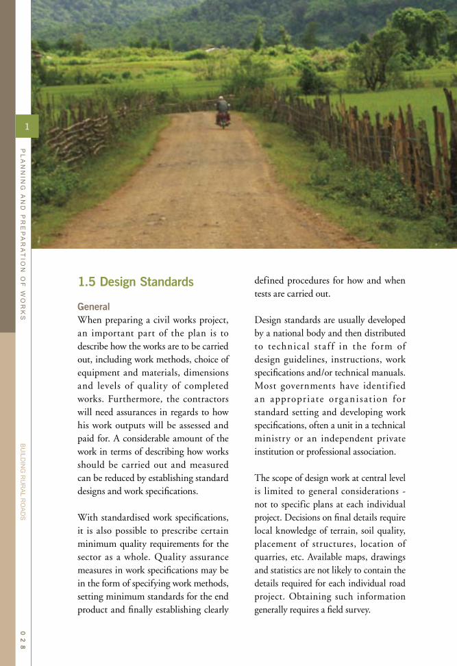
1.5 Design Standards
GeneralWhen preparing a civil works project, an important part of the plan is to describe how the works are to be carried out, including work methods, choice of equipment and materials, dimensions and levels of quality of completed works. Furthermore, the contractors will need assurances in regards to how his work outputs will be assessed and paid for. A considerable amount of the work in terms of describing how works should be carried out and measured can be reduced by establishing standard designs and work specifications.
With standardised work specifications, it is also possible to prescribe certain minimum quality requirements for the sector as a whole. Quality assurance measures in work specifications may be in the form of specifying work methods, setting minimum standards for the end product and finally establishing clearly
defined procedures for how and when tests are carried out.
Design standards are usually developed by a national body and then distributed to technica l sta f f in the form of design guidelines, instructions, work specifications and/or technical manuals. Most governments have identif ied an appropr iate organ i sat ion for standard setting and developing work specifications, often a unit in a technical ministry or an independent private institution or professional association.
The scope of design work at central level is limited to general considerations - not to specific plans at each individual project. Decisions on final details require local knowledge of terrain, soil quality, placement of structures, location of quarries, etc. Available maps, drawings and statistics are not likely to contain the details required for each individual road project. Obtaining such information generally requires a field survey.
1
PL
AN
NIN
G A
ND
PR
EP
AR
AT
ION
OF
WO
RK
S
BU
ILDIN
G R
UR
AL R
OA
DS
02
8

Technical design aspects to be dealt with at headquarters are the standard parameters for typical work items. The standards essentially encompass a range of values within which works are allowed to operate. Design standards normally provide general guidelines relating to the following items:
• Alignment requirements: Instructions for setting out
vertical and horizontal curves of the road and how this fits with the terrain.
• Technical performance: Specif ications of maximum
gradients, minimum horizontal and vertical curvature, sight distances, super-elevation, cross-fall, etc.
• Pavement solutions: Guidelines for design of base
course and surface treatment depending on road function and traffic volume.
• Material requirements: Specifications on the ingredients
and quality of common building materials such as gravel, concrete, surface materials, how they are
used and tests to be performed.• Structures: Design guidelines for bridges,
culverts and road protection works and recommendations on the use of local building materials such as stone and timber.
L oc at ion a nd a l i gnment a re of particular importance when designing new road development projects. The final design solutions are based on a number of considerations, many of which are dependent on the specific local conditions. For example, high alignment standards aiming to reduce the number of curves and soft gradients require considerable earth movements, particularly in hilly or mountainous terrain.
This has a detrimental impact on the surrounding environment such a s i nc re a s ed dema nd s for l a nd expropriation, increasing the risk of landslides and erosion as well as higher costs of construction and maintenance. Furthermore such designs are difficult to carry out ef fect ively applying labour-based work methods. Design engineers therefore need to recognise t he impor t a nce of s e lec t ing a n alignment, which at the same time as catering for the technical performance requirements of the road, also address other important aspects such as social and environmental concerns.
The selection of design standards is related to road function, traffic volume and terrain. In this respect the design process deals with the following main steps:
1
PL
AN
NIN
G A
ND
PR
EP
AR
AT
ION
OF
WO
RK
S
BU
ILDIN
G R
UR
AL R
OA
DS
02
9
• Establish the road function,• Assess the design traffic, • Assess other factors affecting the
design (terrain, type and strength of sub-grade, availability and cost of construction materials, etc.),
• Select a geometric design standard (road cross-section, design speed and speed related standards),
• Select an appropriate pavement design (thickness, thickness and type of materials for each pavement layer),
• Assess the need for road structures (bridges, culverts, retaining walls, etc),
• Assess the availability of labour in the vicinity of the road work sites,
• Assess the availability and skills of local contractors.
Like any other type of infrastructure, design standards for rural roads are developed to meet the functional requirements dictated by the users of such facilities. Rural roads are often characterised by their dispersed geographical coverage in order to reach all communities, thereby providing all-weather access to the entire population living in the rural areas. While this feature creates a demand for an extensive network of local roads connecting rural communities to the main roads and highways, each individual road carries limited traff ic as each road serves only one or a small cluster of rural communities.
In order to create an affordable road network it is therefore important to find
cost-effective solutions which still meet essential performance requirements and essentially keep the roads open and accessible throughout the year in all types of weather.
Equally important is the need to arrive at technically sound design solutions that keeps future maintenance costs at a minimum. This implies that the roads need to be properly designed and built to withstand the prevailing weather conditions as well as being able to cater for the expected type and volumes of traffic.
The selected design should be justified economically and the optimum choice of design depends on the total life cycle cost, including both the costs of construction and ensuing maintenance.
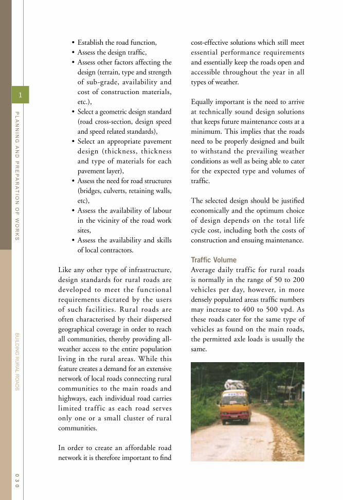
Traffic VolumeAverage daily traffic for rural roads is normally in the range of 50 to 200 vehicles per day, however, in more densely populated areas traffic numbers may increase to 400 to 500 vpd. As these roads cater for the same type of vehicles as found on the main roads, the permitted axle loads is usually the same.
1
PL
AN
NIN
G A
ND
PR
EP
AR
AT
ION
OF
WO
RK
S
BU
ILDIN
G R
UR
AL R
OA
DS
03
0

Cross-sectionsRoad widths essentially determine the size of the road and all its components. To limit construction and future maintenance costs, the width of the road should be kept at minimum dimensions that still allow sufficient space for the traff ic to operate. For access roads with low volumes of traffic, a single lane, 3 to 3.5 metres wide, is sufficient. In remote regions with very limited traffic or in mountainous terrain where it is difficult (or expensive) to establish a full carriageway width, it is common to consider a narrower road width of 3 – 3.5 metres.
This road width will cater for the largest vehicles expected on a rural road. A typical double axle truck has an overall width of 2.2 - 2.5 metres. Meeting vehicles can pass each other at designated meeting places or by using the road shoulders.
On roads with increased traffic, passing manoeuvres increase and it is worthwhile to increase the pavement width to cater for the operation of two vehicles next to each other. Still, with moderate traffic, a 4.5 to 5 metres wide road is sufficient to deal with the meeting vehicles. Vehicles would need to slow down when passing, however, if the traffic is moderate, this will have limited impact on travelling time. Shoulders on each side of the paved road width will facilitate the manoeuvring of meeting traffic as well as any vehicles parked on or next to the road.
In populated areas with higher levels of traffic, an increase in pavement width is
Types of Terrain
Geometric design standards are dependent on the topo-graphical features of terrain through which the road passes. Road engineers commonly classify the terrain as flat, rolling or mountainous, depending on the average ground slope.
Areas with flat terrain obviously offer most options in terms of choosing the road alignment. In rolling terrain, it is essential to align the road parallel to the contour lines of the terrain, while in mountainous the task is to find the "easiest" way through.
Road construction in mountainous te r rain p rovides the la rges t engineering challenges and is the most expensive place to build roads. For this reason, the geometrical standards are often reduced on road sections through mountainous terrain.
Road construction in flat terrain can also be costly as such areas may be prone to flooding. Due to the flooding of the terrain, the road levels need to be elevated to a safe level above prevailing flood levels, often involving extensive earth fills.
The easiest type of terrain for road construction is essentially through gently rolling terrain with moderate slopes. Rural roads through such areas can follow the contours of the terrain, with excavation works limited to small amounts of cut and fill. This type of terrain has good drainage features with less occurrence of soil erosion. With a well-designed alignment, roads through this type of terrain will perform well with a minimum of maintenance.
1
PL
AN
NIN
G A
ND
PR
EP
AR
AT
ION
OF
WO
RK
S
BU
ILDIN
G R
UR
AL R
OA
DS
03
1

justified. A running surface of 5.5 to 6 metres will allow most vehicles to pass each other without having to slow down.
Shoulders are commonly installed on roads for the purpose of providing additional manoeuvring space for traffic to meet and also for parking and stopping purposes without impeding passing traff ic. Shoulders are also often used for non-motorised traffic. Shoulders are commonly left unpaved, however, in areas where soils are prone to erosion, it is more effective to extend the pavement to protect the shoulders.
Design SpeedDesign speeds are normally low on rural roads. This allows the road curvature to be f itted gently into the existing terrain thereby reducing the amount of excavation works. Most rural roads have a limited length so the design speed is not as important as for highways. The most important function of these roads is to provide basic all-year access.
Savings in travelling time due to higher design speeds and resulting straighter curvature is of less importance.
Road GradientsFour-wheel drive vehicles can climb gradients up to 20 percent while two wheel drive trucks can successfully negotiate gradients of 15 percent, expect when heavily loaded. Steep gradients will severely limit the performance of animal drawn carts.
Maximum gradients on rural roads are mainly justified from a maintenance perspect ive, a s roads with steep longitudinal gradients are diff icult to maintain. For this reason it is recommended that the gradient is kept below 8 percent on gravel or earth roads. If, however, it is necessary to use a steeper gradient, it should be limited to a short section. In addition, it would then be useful to consider using a stronger pavement, and also installing preventive measures to limit the erosive effect of run-off water both on the road surface as well as in the drains.
CamberWhen applying concrete or bitumen based road surfaces, a 3 to 4 percent cross fall is suff icient. However for gravel or earth surfaces, it is necessary to increase this gradient to at least 6 percent. On gravel roads with a double sloping camber, it would be preferable to install an 8% cross fall, while on a single sloping camber (often applied on the narrower roads), one would prefer a 6% slope. To secure these camber gradients, the surface is often set out at a gradient 1 or 2 percent higher during
1
PL
AN
NIN
G A
ND
PR
EP
AR
AT
ION
OF
WO
RK
S
BU
ILDIN
G R
UR
AL R
OA
DS
03
2

construction in order to reach the correct levels after compaction.
SurfaceMost rural roads are either earth roads or provided with a gravel surface. On roads with limited traffic numbers, the most important components of the road are those related to drainage. Equally, the main maintenance tasks on such roads are related to managing surface water and taking preventive action to reduce its detrimental effect on the road. Where traffic numbers are higher, it is necessary to consider more durable
surfacing options, such as bitumen or concrete based surface treatments. The old rule of thumb was to use gravel surfacing for roads with traffic numbers less than 100 vpd, however, this threshold depends on a number of local factors such as hauling distance to materials, cost of works, weather conditions, availability of alternative materials, etc.
It is also useful to apply a bitumen-based surface on short sections with
steep gradients, to contain future maintenance requirements on these sections. Equally, bitumen based surfaces are recommended on roads with low traffic levels when passing through villages, for environmental reasons - mainly relating to dust control.
Maximum Axle LoadsAn important role of rural roads is to facilitate the transport of agricultural goods from farms to markets. This is often carried out by merchants travelling to the villages to buy the produce. The transport is normally organised through the use of trucks, which can carry considerable axle loads.A properly engineered road, despite its narrow dimensions, can still cater for this kind of traffic. Equally, with the limited numbers of vehicles passing on these roads, they will also be able to carry this type of traffic over time. It is believed that with current designs, and provided that quality building materials and workmanship are secured, these roads are able to cater for the prevailing axle load limitations.
StructuresDue to the limited traff ic on rural
1
PL
AN
NIN
G A
ND
PR
EP
AR
AT
ION
OF
WO
RK
S
BU
ILDIN
G R
UR
AL R
OA
DS
03
3

roads and the need for extensive networks of such roads in order to reach all communities, design standards emphasise technical solutions which are low cost but at the same time provide the required all weather access. Appropriate solutions are also chosen for river crossings and other structures that can limit the total costs.
Therefore, the design guidelines for structures on rural roads are made simple so that they can be designed, built and maintained relying on locally available skills.For small bridges and other drainage structures, there is a great potential for utilising local contractors if the design
standards take into consideration locally available skills and materials.
Culvert pipe production can be organised as a local industry, mainly requiring some skilled labour and limited amounts of equipment. If the local industry receives suff icient advance notice on future requirements, the supply and installation of pipes can be organised through loca l manufacturers and bui lding entrepreneurs.
Locally available stone can be used in abutments, piers, wing walls and retaining walls. The supply of stone can be awarded to petty contractors and farmers in the vicinity of the work site.
1
PL
AN
NIN
G A
ND
PR
EP
AR
AT
ION
OF
WO
RK
S
BU
ILDIN
G R
UR
AL R
OA
DS
03
4

The direction of the centre line of the road.The portion of the side drain from the ditch invert to the intersection with the natural terrain.That portion of the roadway intended for the movement of vehicles (excluding shoulders).The carriageway camber consists of a straight line cross-fall from the centre line to the shoulders. In super-elevated curves the camber is replaced with a single cross-fall across the entire carriageway.
The layer above the sub-grade in its final shape, often consisting of the excavated soil from the side drains. The camber formation is the layer on which the gravel course is placed.A theoretical line along its longitudinal axis dividing the road equally in two parts.The highest point of the road, located on the centre line when the surface is shaped with a camber.The cross-section profile of the side drain from the side slope to the back slope.The top layer of a gravel road. Also referred to as a surface course or gravel wearing course.The surface of the sub-grade in its final form after completion of the earthworks. The cleared portion of land where the road and all its components will be built.The area normally used by the traffic, consisting of the carriageway and shoulders.The point at which the side slope of the ditch and the carriageway intersect. The drainage channel along the shoulders of the road which collects run-off water from the carriageway and which prevents water from the surrounding terrain from reaching the road surface.The portion of the side drain from the shoulder break point to the ditch invert. The existing natural soils on which the road pavement is placed.
A drainage structure allowing water to pass under the road pavement to be discharged on the lower side of the road.A basket made of wire and filled with stone.A structure which allows water to cross the road, and which at the same time provides a firm surface for vehicles to pass through the water course.The rate of rise or fall in relation to the horizontal along the length of the road or other structure (e.g. a drain).A drainage channel used for leading water away from the side drains into the surrounding, lower terrain, also referred to as a turn-out drain.A construction across a drainage ditch with the purpose of reducing the gradient of the channel in order to slow down the speed of water.
A drainage channel running parallel to the road which collects water from the surrounding higher lying terrain before it reaches the road
Alignment:Back slope:
Carriageway:Camber:
Camberformation:
Centre line:Crown:
Ditch invert:Gravel course:Road formation:Road reserve:Roadway: Shoulders: Side drain:
Side slope:Sub-grade:DrainageCulvert:
Gabion:Drift:
Gradient:
Mitre drain:
Scour check:
Catchwater drain:
Terms and Definitions
1
PL
AN
NIN
G A
ND
PR
EP
AR
AT
ION
OF
WO
RK
S
BU
ILDIN
G R
UR
AL R
OA
DS
03
5

1.6 Technology Choice
Rural infrastructure works can be carried out using a wide variety of work methods and types of equipment. In developing countries, labour wages are often low so the use of manual labour to carry out a number of civil works activities still remains more cost-effective than using heavy construction equipment.
There are several categories of rural infrastructure improvement programmes that use large numbers of unskilled labour:
• Relief Programmes responding to natural or man-made catastrophes, (i.e. droughts, severe floods, war, etc). in which the prime objective is to provide food and income to the affected individuals. Although such progra mmes may a l so improve infrastructure, this is considered as a secondary effect.
• E m p l o y m e n t G e n e r a t i o n Programmes - These projects often give limited attention to cost and quality effectiveness since the asset creation is a secondary objective.
• Asset-Creation Programmes - These programmes have as their primary objective to improve infrastructure at competitive costs, mainta ining accepted design and quality standards and applying the most appropriate technology. Simultaneously, they supply employment opportunities in the rura l areas, providing supplementary cash income.
To avoid a common misconception, it is important to distinguish between labour-based methods and labour-intensive methods. In contrast to labour-based technology, a labour-intensive approach seeks to maximise the use of labour with minimum use of mechanised equipment, often at the expense of cost and quality efficiency.
Labour-based technology can be defined as the construction technology which, while maintaining cost competitiveness and acceptable engineering quality standards, maximises opportunities for the employment of labour (skilled and unskilled) together with the support of light equipment and with the utilisation of locally available materials and other resources.
Work MethodsAs mentioned earlier, labour-based methods do not exclude the use of equipment. The way labour-based works technology has been adapted to the functional requirements of the completed roads implies that a considerable amount of equipment is still required. For comparison, the table below shows the most common equipment used for building rural roads,
1
PL
AN
NIN
G A
ND
PR
EP
AR
AT
ION
OF
WO
RK
S
BU
ILDIN
G R
UR
AL R
OA
DS
03
6

either applying labour-based works technology or relying on conventional equipment intensive methods.
The construction of common structures such as culverts, bridges and retaining walls generally rely on an appropriate mix of skilled and unskilled labour and some equipment. In terms of choosing the most appropriate technology for this type of works, it is more important to select materials which are locally available and to the extent possible reduce the amount of materials which needs to be imported from far away.
For both the road works and the structural works, it is important that the designs are developed in a manner which, to the extent possible, allows for works to be executed relying on locally available resources. This applies not only to the choice of materials but also relates to the choice of technology. Rural roads essentially consist of simple engineering structures and do not require any complicated technology, equipment or work methods. For this type of civil works it is possible to rely on mainstream engineering technology, and by keeping it simple it may be possible to use local builders and contracting firms to carry out the works.
A s long a s the technolog y choice remains simple, it should have very limited impact on the ensuing works implementation arrangements. The works can then still be carried out using local contractors or if required by force account. When applying labour-based methods, the main difference is that the works rely on the effective organisation and supervision of a large labour force. This may be a new experience for the technical staff, requiring some initial training in order to reach the full potential of labour-based works technology.
The use of labour-based work methods also allow for an increased participation of local communities in the works. This can either be organised through the employment of local inhabitants as part of the labour force or by contracting out parts of the works to community groups. Equally, local villagers can be involved through the provision of locally available building materials.
The technology choice is normally specified in the works specifications. S i n c e m o s t s t a n d a r d t e c h n i c a l specif ications describe both methods and performance requirements of the end product, it is necessary to modify these documents in order to reflect the technology choice.
1
PL
AN
NIN
G A
ND
PR
EP
AR
AT
ION
OF
WO
RK
S
BU
ILDIN
G R
UR
AL R
OA
DS
03
7
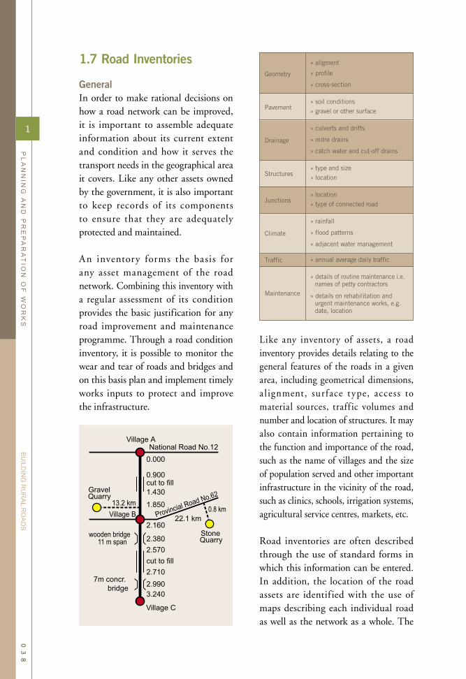
1.7 Road Inventories
GeneralIn order to make rational decisions on how a road network can be improved, it is important to assemble adequate information about its current extent and condition and how it serves the transport needs in the geographical area it covers. Like any other assets owned by the government, it is also important to keep records of its components to ensure that they are adequately protected and maintained.
An inventory forms the basis for any asset management of the road network. Combining this inventory with a regular assessment of its condition provides the basic justification for any road improvement and maintenance programme. Through a road condition inventory, it is possible to monitor the wear and tear of roads and bridges and on this basis plan and implement timely works inputs to protect and improve the infrastructure.
Like any inventory of assets, a road inventory provides details relating to the general features of the roads in a given area, including geometrical dimensions, a l ignment, surface type, access to material sources, traff ic volumes and number and location of structures. It may also contain information pertaining to the function and importance of the road, such as the name of villages and the size of population served and other important infrastructure in the vicinity of the road, such as clinics, schools, irrigation systems, agricultural service centres, markets, etc.
Road inventories are often described through the use of standard forms in which this information can be entered. In addition, the location of the road assets are identified with the use of maps describing each individual road as well as the network as a whole. The
1
PL
AN
NIN
G A
ND
PR
EP
AR
AT
ION
OF
WO
RK
S
BU
ILDIN
G R
UR
AL R
OA
DS
03
8

maps range from simple hand drawn strip maps to advanced computerised graphical information systems (GIS) in which all the data is linked to a digitalised map. Although modern GI systems are impressive and allow for an efficient management of data, it should be stressed that these systems are not essential for the effective management of information relating to a rural road network. Experience clearly shows that even a simple system of manually prepared strip maps can be an effective planning tool for the development and maintenance of rural roads.
Maps and Graphical PresentationsMaps form an important basis for the planning of any type of infrastructure. They prov ide a good g raph ic a l presentation of the transport needs and patterns in a given area, and together with data relating to the location of villages, economic activities and social services, it is possible to establish a good overview of the transport situation.
The use of maps for infrastructure planning is carried out at two levels, (i) for the overall planning of development works in a given area, and (ii) for the specific
1
PL
AN
NIN
G A
ND
PR
EP
AR
AT
ION
OF
WO
RK
S
BU
ILDIN
G R
UR
AL R
OA
DS
03
9

required in order to maintain and improve the condition of the road network. Maps are therefore used for specifying works in detail and are often included as part of project designs and contract documents. Together with information on the condition of the network, they provide a good overview of the network as a whole.
As mentioned earlier, maps can be produced using various methods. With the increasing application of GIS for rural development purposes, it is often possible to obtain good and up to date digital maps. If these are not available, the alternative is to produce simple road maps from old topographical maps or aerial photographs. Even without such basic information, simple strip maps can always be produced based on the actual travelling distance measured during road surveys.
Road Condition SurveysIn order to assess the needs for and to plan future improvement and maintenance works, it is necessary to maintain an intimate and up-to-date knowledge of the condition of the road
purpose of planning individual road maintenance and improvements works.
A basic feature of maps is that they provide a good overview of where people live and how communities are connected together through various means of transport such as roads, tracks, railways, rivers, etc. For development planning purposes, information on economic activities and social services can be added to the map and used during discussions relating to the overall development of a specific region. With the inclusion of such information, it is possible to obtain a good overview of how various sectors interact with each other. From the point of view of establishing an effective road network, the information relating to other sectors can improve the understanding of how the roads provide the necessary transport links required in other sectors (access to schools, clinics, markets, local government head-quarters, etc.).
For engineers and technicians in charge of the management of a road network, the use of maps is more specifically related to locating where works are
1
PL
AN
NIN
G A
ND
PR
EP
AR
AT
ION
OF
WO
RK
S
BU
ILDIN
G R
UR
AL R
OA
DS
04
0

network. For this reason, it is common practice to carry out regular road condition surveys. These surveys form the basis for future work programmes and funding requirements so they need to be carried out well in advance of the next budget approval process. Road condition surveys allow the road authority to:
• become thoroughly familiar with the road network and its maintenance problems and as a result make objective and quantif ied assessments of the conditions of each road,
• rev iew the e f fec t iveness of maintenance activities carried out since the previous inspection, and
• programme improvement and maintenance works to be carried out in the next construction season.
A road works unit is normally in charge of an extensive road network and with the limited resources and time available, it is necessary to assess the condition of the roads in an accurate and timesaving manner as possible. Therefore, it is useful to concentrate on the identification of defects using a few well-def ined key indicators describing the roads. Such indicators must be defined for each programme and will depend on local conditions and requirements. However, there are some features that need attention on all roads:
• overall performance of road (i.e. providing all-year access),
• drainage features,
• performance of cross-drainage structures such as bridges and culverts
• quality and performance of pavement,
• extent to which current design is effective in terms of dealing with weather and traffic without causing excessive maintenance demands,
• containing possible environmental problems such as landslides and soil erosion,
• road safety problem spots.
Road authorities will normally establish clear procedures for preparing road condition inventories to be applied during various stages of planning of construction and maintenance works. This information should be stored and later updated when future improvement works are carried out.
1
PL
AN
NIN
G A
ND
PR
EP
AR
AT
ION
OF
WO
RK
S
BU
ILDIN
G R
UR
AL R
OA
DS
04
1

The survey work is a continuous process carried out on a regular basis to monitor the performance and condition of the road network. Equally, the budget preparations are normally carried out a year in advance and therefore based on earlier preliminary assessments of the road condition and required improvement works. When specif ic road improvement or new construction project are proposed, it is necessary to carry out a detailed survey specifically for this purpose.
When the work budgets have been secured, detailed designs and work plans are prepared for each road works project. With the detailed plans completed, it is possible to commence the tendering process. Once the contracts have been awarded, the detailed work plans need to be updated to (i) reflect the actual time at which the contractor can commence works and (ii) to reflect the specific arrangements of resources which the contractor intends to make. The plans of individual work projects are finally compiled into an overall programme describing all works under the supervision of the road works agency.
This planning and programming exercise not only applies for construction works but also provides the basis for planning of road maintenance. The planning process should therefore result in two sets of plans, one for the annual maintenance programme and another for road improvement works.
Preparatory ActivitiesThere are several stages of preparations before a civil works programme can commence. These preparatory activities will need staff resources and logistical support in order to be carried out in a timely fashion. For this reason, a schedule of events defining when survey works, design, preparation of bidding documents and the tendering of works will take place is prepared. The figure below outlines the sequence of preparatory activities required in order to secure that the road works take place at the right time.
This time schedule should cover the entire period starting from when the initia l surveys will take place unt i l contract award and work s implementation. This will ensure that the preparatory works are completed at the correct time before the necessary budgets are available and works are intended to start. It also allows for the necessary supervision staff to be mobilised when works are ready to commence.
The first step among the preparatory activities is to establish in detail the composit ion of the actua l works requirements. All works planning is based on field surveys where the actual condition of the road is established in detail. Based on what is observed in the field, it is possible to make specific suggestions on how to improve the road and on this basis calculate quantities of work and estimate costs.
1.8 Planning and Estimating Works
1
PL
AN
NIN
G A
ND
PR
EP
AR
AT
ION
OF
WO
RK
S
BU
ILDIN
G R
UR
AL R
OA
DS
04
2

1.9 The Design Process
The process of design and cost estimating follows a series of distinctive steps as illustrated in the f igure below. The first result of this exercise may warrant some reassessment of the inputs to the estimates, before submitting the results for final approval and funding. Although some of the activities need to be carried out in detail only once, it is important that all parties involved carefully study the drawings and other technical documents in order to arrive at a common understanding of the contents of the works. The client, or the consultants engaged by the owner of the infrastructure, is responsible for preparing the designs. The process of cost estimating however needs to be carried out by both the client as well as the contractor.
The first step in the process is to survey and record the conditions in which the works wil l be carried out. In the case of the construction of new roads, a road alignment needs to be determined during the field surveys. With rehabilitation works, it is common practice to remain a long existing alignments to avoid the need to acquire
1
PL
AN
NIN
G A
ND
PR
EP
AR
AT
ION
OF
WO
RK
S
BU
ILDIN
G R
UR
AL R
OA
DS
04
3

additional land. Civil works related to structures will also require a thorough field survey to establish topography, soil conditions, drainage patterns, access to site, etc.
Design standards provide guidance in terms of how the works are to be carried out. Based on the functional requirements, the designer will propose the appropriate design solut ions according to prevailing government guidelines. The selected designs will then be adapted to the specif ic site conditions. On the basis of the detailed designs and how these are adjusted to the prevailing site conditions, it is then possible to calculate the exact quantities of work. The type and amount of work is then presented with the use of drawings, works specifications and finally a bill of quantities.
Although the overall construction methods are often defined in the work specifications, the designers still need to take a number of detailed decisions related to work methods, choice of equipment, type of materials, etc. These decisions form the basis for the
calculation of production rates, which in the next turn will determine the duration of each of the work activities.
Finally when a work schedule has been assembled on the basis of the above information, and when current prices have been collected on labour, materials and equipment, it is possible to estimate the costs of each of the work activities and f inally produce a detailed cost estimate for the entire project.
This exercise is often carried out for several alternatives, using various types of materials, work methods and designs. Finally, when satisfactory results have been achieved, the estimates need to be approved and the funding released.
Planning the Design StageAll the above activities needs to be planned in an organised manner, with staff assigned to various job responsibilit ies which need to be completed before agreed deadlines. The time available for the design stage is often limited since the client will be eager to commence works as soon as possible. The allocated budgets
1
PL
AN
NIN
G A
ND
PR
EP
AR
AT
ION
OF
WO
RK
S
BU
ILDIN
G R
UR
AL R
OA
DS
04
4

may have to be spent before a certain deadline, and once funding has been identified, all parties involved will start looking forward to the completion of the works. For these reasons, it is useful to prepare a time schedule, indicating when the outputs of the various preparatory activities will be complete. Knowing how much time is required for the design work will provide an indication of when the tendering stage can commence and f inally when a contractor can start the works.
In some cases it is useful to explore severa l design a lternatives before making a f inal choice. When still exploring the options, it is important to limit the amount of detailed design works. A full and detailed design and work plan should only be prepared when there is sol id commitment in terms of funding and executive agreement supporting the decision to carry out the project in the immediate future (such as in the coming budget year).
The detailed design of a civil works project involves a substantial amount of work and will require considerable staff resources either from in-house technical units or from external consultants. Equally, detailed designs have a certain shelf life before they become obsolete and need to be updated (involving additional resource intensive surveys and redesign work).
1.10 Road Alignments
Once a road connection has been given suff icient priority in order to allocate funding for its construction or improvement, the exact alignment is established. This is the stage at which the physical conditions in the area are assessed in detail, including topography, soil conditions, optimal river crossings and other general features influencing the cost of the project.
The initia l step in identifying an appropriate alignment is carried out by reviewing ava i lable maps and aerial photographs. This provides the designers with an overall picture of the role and function of the road in relation to the population and travel patterns in the area, and also gives some indication of how the road needs to be adapted into the terrain.
When the approximate alignment has been identified on a map, a detailed survey needs to be carried out in order to establish the exact location of the road and all its components. Only then will it be possible to estimate the precise quantities and costs of the work.
1
PL
AN
NIN
G A
ND
PR
EP
AR
AT
ION
OF
WO
RK
S
BU
ILDIN
G R
UR
AL R
OA
DS
04
5

For major roads and highways, survey and design works are carried out to very high levels of accuracy, often relying on advanced methods of surveying and data processing. On highways, such work is often carried out using digitised maps and computer-assisted design tools, either by an "in-house"
design unit or by engaging external consultants. Rural roads require a lower level of detail. Survey and design is often under the responsibility of local government agencies which do not possess these sophisticated design tools. As shown in later sections in this manual, the detailed design of rural road alignments can be carried out using simplified work methods relying on simple and inexpensive setting out equipment, and still achieve sufficient levels of accuracy and detail. As a result, the costs of the design works can be limited and the works can be carried out by the local government road unit.
Alignments for rural roads commonly fol low exist ing tracks and tra i ls. When roads are reconstructed or rehabilitated there would normally be limited changes to the alignment as there may still be some residual value in the existing facilities such as embankments, side cuts, culverts, and bridge structures. Following existing alignments will also minimise the need for land expropriation.
When constructing new roads with completely new alignments it is however important to adjust the route in line with the above mentioned guidelines. As a first step, it is useful to sketch the route on a topographic map or an aerial photograph. This will provide an improved picture why a particular alignment has been chosen, showing the key factors which have influenced the process. The final route selection would of course need to be verified with site inspections and surveys. Based on the field surveys, a map with the exact
Good Road Alignments
The determination of a good alignment is more dependent on experience and good judgement by the designer than the availability of advanced surveying and processing equipment.
By selecting an alignment which follows the terrain and minimises earthworks, both initial construction costs as well as future maintenance requirements can be reduced. This includes design principles such as:
• Crossing ridges at their lowest point or through the lowest pass;
• Circumventing hills rather than going straight over;
• Avoiding deep cuts, thereby reducing earthworks and avoiding to destabilise side slopes;
• Avoiding excessive fills by realigning the road, preferably to locations where a cut-to-fill is sufficient;
• Finding the highest lying ground when passing through flood-prone terrain;
• Avoiding steep road gradients;• Avoiding rocky terrain or areas
with difficult soils; • Locating good river crossings
where there are limited risks of future scouring and erosion.
When determining the optimal road alignment it is important to assess how each road section will perform in terms of future maintenance requirements. The most effective preventive maintenance measure lies in the actual design of the road.
1
PL
AN
NIN
G A
ND
PR
EP
AR
AT
ION
OF
WO
RK
S
BU
ILDIN
G R
UR
AL R
OA
DS
04
6

location of the road alignment can then be prepared, including information relating to road levels, location of structures and other key features in the vicinity of the road.
When collecting information regarding the site conditions, it is important that it is recorded in an organised manner which can easily be referred to at any
time during the duration of the road works project. For this purpose, it is helpful to use a standardised form where the details of the envisaged works are recorded.
Once the initial road alignment has been determined, the Engineer can carry out a survey of the road to estimate the amount and location of construction
1
PL
AN
NIN
G A
ND
PR
EP
AR
AT
ION
OF
WO
RK
S
BU
ILDIN
G R
UR
AL R
OA
DS
04
7

works. Information about road curvature, earthworks (cut to fill, embankments, etc.) and drainage structures (bridges, culverts, mitre drains, scour checks, etc.) is then plotted in the road alignment drawings at its exact chainage along the road alignment.
Surveying new alignments is a resource-intensive activity. It requires skilled technical staff for a considerable time in order to complete the works in a professional manner. For this reason, it is useful to schedule this type of work to periods of the year when the staff is less involved in supervision of on-going works, such as during the rainy season. Survey work also requires good logistical support as the staff needs to travel to the field on a daily basis. Where the future road is passing through dense forest, it may also be necessary to hire a small group of workers for bush clearing thereby providing the necessary sight lines for the surveyors.
For ex i st ing roads on which no major changes are envisaged to the road alignment, the proposed road improvement works can be recorded in a table briefly recording the assessment of the current road condition together with the proposed improvement where deficiencies are observed. Using such a form, information can be quickly recorded for any given section of a road.
Roadside DevelopmentRural roads are meant to serve the people living alongside it or in the villages in the vicinity of the road. As a result they will be entering the road at any point and will be establishing simple connections
between their access roads and the rural roads. Equally, people in the rural areas will choose to establish their new houses or business premises close to the rehabilitated or improved roads.
In this process, it is important that the authorities in charge of the roads make sure that the road and all its components are not compromised in any manner as a result of the connections made or the new building activities taking place close to the road. Particular attention needs to be given to maintaining the established drainage system of the road, ensuring that any connections made to the road do not block or constrict the side drains. Equally, the building activities in the vicinity of the road should be held at a safe distance, maintaining the clearance provided in the road reserve.
Roadside development may also cause new safety concerns. A lthough it may be difficult to avoid people and businesses establishing themselves along the roadside, the road alignment can always be directed away from the existing settlements. Rather than directing the road straight through the centre of villages, it is always a safer solution to find an alignment in which the road passes by at the outskirts of the communities. Similarly, it is strongly recommended to keep the road alignment away from places where people congregate, such as health centres, schools and town centres and market places. Instead it is better to provide a short access road between the main road and these facilities, allowing long-distance traffic to pass by at a safe distance.
1
PL
AN
NIN
G A
ND
PR
EP
AR
AT
ION
OF
WO
RK
S
BU
ILDIN
G R
UR
AL R
OA
DS
04
8
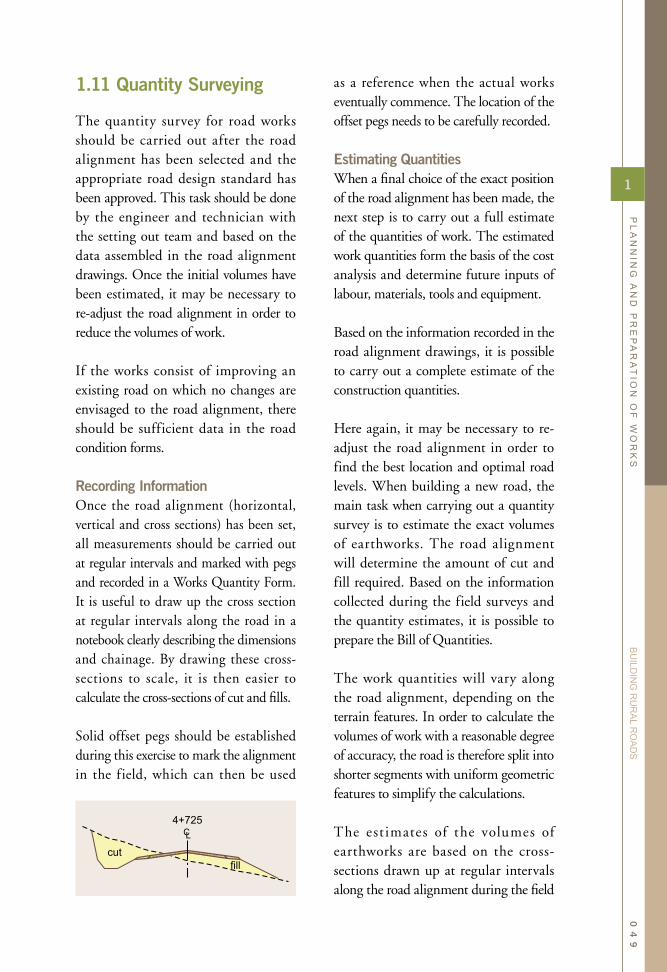
1.11 Quantity Surveying
The quantity survey for road works should be carried out after the road alignment has been selected and the appropriate road design standard has been approved. This task should be done by the engineer and technician with the setting out team and based on the data assembled in the road alignment drawings. Once the initial volumes have been estimated, it may be necessary to re-adjust the road alignment in order to reduce the volumes of work.
If the works consist of improving an existing road on which no changes are envisaged to the road alignment, there should be sufficient data in the road condition forms.
Recording InformationOnce the road alignment (horizontal, vertical and cross sections) has been set, all measurements should be carried out at regular intervals and marked with pegs and recorded in a Works Quantity Form. It is useful to draw up the cross section at regular intervals along the road in a notebook clearly describing the dimensions and chainage. By drawing these cross-sections to scale, it is then easier to calculate the cross-sections of cut and fills.
Solid offset pegs should be established during this exercise to mark the alignment in the field, which can then be used
as a reference when the actual works eventually commence. The location of the offset pegs needs to be carefully recorded.
Estimating QuantitiesWhen a final choice of the exact position of the road alignment has been made, the next step is to carry out a full estimate of the quantities of work. The estimated work quantities form the basis of the cost analysis and determine future inputs of labour, materials, tools and equipment.
Based on the information recorded in the road alignment drawings, it is possible to carry out a complete estimate of the construction quantities.
Here again, it may be necessary to re-adjust the road alignment in order to find the best location and optimal road levels. When building a new road, the main task when carrying out a quantity survey is to estimate the exact volumes of earthworks. The road alignment will determine the amount of cut and fill required. Based on the information collected during the field surveys and the quantity estimates, it is possible to prepare the Bill of Quantities.
The work quantities will vary along the road alignment, depending on the terrain features. In order to calculate the volumes of work with a reasonable degree of accuracy, the road is therefore split into shorter segments with uniform geometric features to simplify the calculations.
The est imates of the volumes of earthworks are based on the cross-sections drawn up at regular intervals along the road alignment during the field
1
PL
AN
NIN
G A
ND
PR
EP
AR
AT
ION
OF
WO
RK
S
BU
ILDIN
G R
UR
AL R
OA
DS
04
9

survey. Based on the chosen road levels, it is then possible to first estimate the areas of the cut and fill in the cross-sections and thereafter calculate the volume between the cross-sections.
One way to do this is as follows:
(i) The alignment is set out with pegs every 10 to 25 metres. The level of the new road is marked on the pegs.
(ii) At each section the height and width of excavation (or fill) is estimated and noted. Alternatively, the cross fall gradient can be measured using a line level and ranging rods.
(iii) The average cut height and width is calculated for each section.
(iv) The quantities of other work
activities are included. (v) The sum of these quantities
represents the total volumes of work for the road project.
It is also possible to prepare a strategy for how the work is to be carried out, making decisions on appropriate work methods, t ype and quant it ie s of equipment required, packaging of contracts, etc.
With the work quantities established, a time plan and cost estimates can be prepared for the project based on the resources available and their respective unit cost rates (i.e. labour, materials, tools and equipment).
1
PL
AN
NIN
G A
ND
PR
EP
AR
AT
ION
OF
WO
RK
S
BU
ILDIN
G R
UR
AL R
OA
DS
05
0

Preparing a Work ScheduleThe preparat ion of a project work schedule is useful for a number of reasons. A works programme is necessary in order to estimate the duration of equipment and labour inputs. A lso, the work schedule will determine when the funding of the works needs to be made available. If the project duration is more than one year, the required funding needs to be distributed over several budget years. Equally important, is the wish to carry out the works within a certain timeframe. Therefore, a work schedule is required in order to determine the appropriate start and completion dates of the works and thereby indicate when the services of a contractor will be required.
Finally, a specif ic project may be a component of a larger works programme. It is therefore important that the work schedule of each individual project is well established in order to coordinate all programme components.
If the client decides to award separate contracts for some of the operations, i.e. separate contracts for structures and gravelling, it is important to know the exact schedule of all activities so that the start of the various works contracts can be properly coordinated.
Work scheduling is equally important for the contractors. In order for the contractor to allocate resources such as workers, equipment and materials, it is vital that the start and duration of all work activities have been properly programmed. This will allow the contractor to make all necessary preparations in order to provide these inputs on time.
Equipment may need to be serviced before being sent to the site. Some equipment may need to be hired, which requires some lead-time in terms of canvassing the market and negotiating acceptable prices. Equally, material suppliers need to be identified and prices need to be canvassed. Labour needs prior
1.12 Time Management Planning
1
PL
AN
NIN
G A
ND
PR
EP
AR
AT
ION
OF
WO
RK
S
BU
ILDIN
G R
UR
AL R
OA
DS
05
1

notice so that they can make appropriate arrangements so their time can be released for work on the project site.
A work schedule is also necessary in order to enable the contractor to establish realistic cost estimates which form the basis of a bid proposal. Costs of certain activities are directly related to the duration of the works. The work schedule describes the exact duration of the works and thereby provides the contractor with essential information required for bid preparation.
Once works commence, the contractor needs a work programme against which progress can be measured. With the work plan, it is possible to identify insufficient works progress at an early stage and take remedial action to improve the performance of certain activities.
Most contracts require the contractor to submit a work programme shortly after the signing of the contract agreement. This work programme will need to be approved by the supervising engineer, before the contractor commences work. Through regular reviews of work progress and during the site meetings, this plan is updated and adjusted to meet any changes of work and unforeseen site conditions.
Inputs to a Work ScheduleA tentative work plan is prepared before the tendering of the works. Once a works contract has been awarded, the contractor is expected to prepare an updated work plan in consultation with management. The estimates of work quantities and the contractors bid
proposal provide the basis for preparing the work schedule. Generally, the work plan will contain the following information:
• type and amount of work by works location,
• workdays and equipment-days (targets) for each work activity,
• starting and finishing date for each works activity,
• material schedules,• temporary traffic management
arrangements, • summary totals.
In order to prepare this plan of works, there are certain t ypes of informat ion the planner needs to access. When starting the preparation of a work plan, it is important to make an assessment of the required level of detail in the plan. If the project is still in its preliminary stages, there is still no need for detailed planning. It is important to bear in mind that a high level of detail will require more time to prepare the plan and also require more basic information as inputs to the plan.
First of all, it is important to establish the
Mobilising and starting up includes:
• Establishing the site camp,• Recruitment of workers, mobilising
equipment and purchasing materials, and
• Initial surveying and setting out works.
1
PL
AN
NIN
G A
ND
PR
EP
AR
AT
ION
OF
WO
RK
S
BU
ILDIN
G R
UR
AL R
OA
DS
05
2

overall period in which the works can take place, i.e. when it can commence and when all works need to be completed. The particular work, covered by the work plan, may form part of an overall programme, and therefore needs to be carefully coordinated with other works not part of this particular project.
W hen ca lcu lat ing the t imes for construction, the planner must also allow for mobilising and starting up activities, and final completion and clearance of the sites.
Construction works need to start in a logical and staggered way. Some activities will have to start first before other activities can follow. Labour is employed as needed according to the increase of activities at site level.
Completion work includes the final clearing up of the work site, the
dismantling of the camp buildings and, finally, a formal opening ceremony.
The next step is to establish the appropriate rates at which each of the activities should be carried out. Production rates are closely related to the amount of inputs invested into an activity. Increasing the amount of equipment and labour normally achieves a higher production rate. The planner needs to decide on the level of inputs required in order to achieve appropriate level of progress.
Furthermore, the planner needs to take into consideration project specific conditions (i.e. soil types, prevailing weather, availability of labour and equipment, etc.), which may affect production outputs.
Once the outputs have been established, the production rates determine the
Planning the Workforce
For labour-based works, the prevalent task rates determine the overall production rates. Often, the works can then be quantified in terms of how many workdays are required. As an example, the excavation and building of an embankment may require a total of 100 workdays. In order to determine the exact duration of this work, the next step required is to allocate the appropriate number of labourers to this task.
As a starting point, the contractor is interested in completing the work as soon as possible, however, the number of workers recruited needs to be based on several considerations:
• Obviously, there is a limit to how many
persons can physically fit into the area where the task should be carried out without becoming overcrowded;
• There may be a limit to how many workers are available. Equally, the project should maintain a fairly constant size of the work force, rather than hiring and firing people on a regular basis;
• The works need to progress at a certain pace which is in tune with other activities on site.
Where the activity requires some equipment, the total outputs of the workforce need to be in balance with the production capacity of the equipment.
1
PL
AN
NIN
G A
ND
PR
EP
AR
AT
ION
OF
WO
RK
S
BU
ILDIN
G R
UR
AL R
OA
DS
05
3

duration of each of the activities. After sorting out the order of each of the activities, this information combined with start dates and production rates will produce the duration and completion dates for each activity and the works as a whole.
The plan of operation is presented with diagrams such as bar charts and time-location charts. They are distributed to all management levels so that the supervisory staff at each level can prepare for their own responsibilities in carrying out the work on time within the overall plan.
Bar ChartsBar charts or Gantt diagrams are the most common graphical presentation of a work schedule. Since they are easy to prepare, most projects are first described through the use of a bar chart. These charts are not only useful for the programming of physical works, but are also commonly used for the preparatory stages such as planning and identification of works, preparation of contract documents and the bidding process.
The example below shows an overall bar chart describing a project from its
initial planning stages through to the completion of the construction works.
Work plans are prepared to various degrees of detail, depending on the audience and purpose of the planning. The adjacent bar chart outlines the overall schedule of a project. This plan will need further detailed planning of each activity before works commence.
The example on the next page shows a more detailed plan for the execution of the physical works. The same level of detail can also be applied to the preparatory stages by splitting them into more detailed activities.
The work schedule can be broken down into more detailed sub-activities. For example, the bridge works can be described in detail by specifying the start and duration of excavation works for the foundations, construction of abutments, form works for the bridge slab, pouring of concrete, curing, diversion of water and traffic, etc.
Bar charts do not indicate the progress during the course of a specific activity - they only indicate when an activity starts and when it ends. For this reason,
1
PL
AN
NIN
G A
ND
PR
EP
AR
AT
ION
OF
WO
RK
S
BU
ILDIN
G R
UR
AL R
OA
DS
05
4

it may be useful to complement the chart with information related to the specific progress expected. Using the sample shown above, one could add the monthly production outputs for each of the activities presented in the chart.
Once works actually commence, the actual construction outputs can be entered into the work plan, thereby enabling easy comparison with the originally planned progress. In the f igure above, the actual production outputs have been entered up to the month of May. The planned production is indicated as completed kilometres above each bar and the actual outputs underneath the bars.
In this sample, the figures show the production for each month. As an alternative method, it may be more usefu l to record the cumulat ive production outputs.
Time Location ChartsRoad construction works has the very unique feature that its progress can be measured on the basis of its location along the road section which has been
selected for improvements. This implies that when the construction works is taking place at the start of the road, this often indicates that the works have just started. Equally, if the work is taking place towards the end of a road section, this would imply that a majority of the works have already been completed. Although it is perfectly feasible to start the works at any given location along the road alignment, the actual progress of works is reflected in the portion of the road length that has been completed. For this reason, the progress can be described as a function of the completed length of road. This relationship is therefore presented as a time-location graph in which the one axis describes the location to which works have been completed plotted against another axis depicting the time or date.
Both planned as well as actual work progress can be described with the use of time-location diagrams. Since the road works activities normally start at one or at most two locations, and advances in a linear fashion along the road line, it is possible to forecast the progress of works at any given time as a
1
PL
AN
NIN
G A
ND
PR
EP
AR
AT
ION
OF
WO
RK
S
BU
ILDIN
G R
UR
AL R
OA
DS
05
5

function of linear metres completed. By plotting the planned works as a simple line graph, it is easy to determine when works are complete at any given location along the road.
The simplest use of a time-location chart is shown in the figure below. This chart describes the planned progress of a road rehabilitation project of 15 km, expected to be completed within a duration of 10 months.
From the graph, it is possible to read the following information. The works will commence in December at the start of the road, and will be completed by the end of September the following year. From the gradient of the line graph, it is possible to calculate the production rate during a certain month. A steep gradient implies that the rate of progress is high, while a slower increase would describe a lower monthly production output (as seen from the month of July onwards). Finally, the graph describes the cumulative progress at any time during the duration of the works. For example,
by the end of February, it is expected that 5 km will be completed.
The client may wish to complete the works over a shorter time and therefore plans that two work teams are engaged, each team starting from separate ends of the road working towards each other. If the output rate of each team is equivalent to the original plan where only one team was utilised, the time location diagram would look like the graph shown in the figure on the next page. From this time location chart, it can be seen that the works will then be completed by the middle of May.
Time location charts can also be broken down into more specif ic activities. For road rehabilitation works, it is normal practice to plan each of the main operations in detail, i.e. clearing, earthworks, surfacing works and installation of cross-drainage structures. The following time location chart describes a project, in which the planned progress for each of the main work operations is described separately.
1
PL
AN
NIN
G A
ND
PR
EP
AR
AT
ION
OF
WO
RK
S
BU
ILDIN
G R
UR
AL R
OA
DS
05
6

operations. As shown in the chart be low, the g rave l l ing operat ion will take place at a faster pace than the earthworks. This is easily seen, since the gradient of the line curve representing the gravelling operation is a steeper than the line representing the earthworks. Actually, the distance between the two work teams carrying out these operations can be measured from the chart as shown below.
From this chart, it is possible to see that the cross-drainage structures are completed after the clearing works have been carried out, but before the earthworks and gravelling operations take place. Since the cross-drainage works are not of a linear type, they are simply described as a bar chart, extending over a certain duration of time at the same location (chainage).
The time location chart also clearly specif ies the spacing of the various
1
PL
AN
NIN
G A
ND
PR
EP
AR
AT
ION
OF
WO
RK
S
BU
ILDIN
G R
UR
AL R
OA
DS
05
7

Resource InputsThere are various other types of information that can be added to a time location chart. An important type of information is the scheduling of equipment and manpower. In the diagram below, information on labour requirements has been added to the time location chart. The labour requirement is important information for recruitment purposes. With this forecasting exercise, it is possible to provide advance notice about the exact need for workers.
Time-location charts are helpful for both planning and monitoring work progress. The physical progress can be entered into the same chart as the originally planned progress. At a glance, it is then possible to see whether the works are ahead or behind schedule. The figure on the next page describes the same time-location chart after work has commenced. From
the chart, it is possible to read that progress up to the end of May consists of completing 11 km of earthworks, roughly according to schedule. Furthermore, the gravelling operation just started during the same month with an output of 2 km compared to a planned output of 3 km.
By extending the line graph describing actual outputs, using the same gradients as achieved during the last month, it is possible to forecast when the works will be completed. In this example the earthworks seems to be following the planned schedule, however, the gravelling operation needs to pick up more speed in order to meet the planned completion date.
Choice of Planning MethodThere are a number of planning methods currently in use in the construction industry. Each method has its strengths and weaknesses and it is therefore important
1
PL
AN
NIN
G A
ND
PR
EP
AR
AT
ION
OF
WO
RK
S
BU
ILDIN
G R
UR
AL R
OA
DS
05
8

that the choice of planning method is relevant to the type of works involved.
For simple projects with a limited number of activities, the bar charts will adequately meet the demands of the user. Bar charts can also be used for a number of different purposes, not only describing construction works, but a lso activities related to planning and preparation of civil works. Finally, since bar charts are the most common method of presenting work schedules, they are easily understood.
The time location diagrams however provide more detailed information which is difficult to present in a bar chart. The time location charts are efficient in terms of monitoring production rates and for this reason they are very useful also for monitoring progress when works are distributed in a linear form.
In order to get the best of both methods, bar and time location diagrams can be combined into the same chart as shown in the sample below.
Monthly Physical Progress
1
PL
AN
NIN
G A
ND
PR
EP
AR
AT
ION
OF
WO
RK
S
BU
ILDIN
G R
UR
AL R
OA
DS
05
9
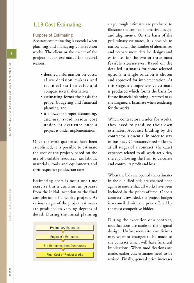
1.13 Cost Estimating
Purpose of EstimatingAccurate cost estimating is essential when planning and managing construction works. The client or the owner of the project needs estimates for severa l reasons:
• detailed information on costs, a l low decision makers and technical staf f to value and compare several alternatives,
• estimating forms the basis for proper budgeting and financial planning, and
• it allows for proper accounting, and may avoid serious cost under- or over-runs once a project is under implementation.
Once the work quantities have been established, it is possible to estimate the cost of the project, based on the use of available resources (i.e. labour, materials, tools and equipment) and their respective production rates.
Estimating costs is not a one-time exercise but a continuous process from the initial inception to the final completion of a works project. At various stages of the project, estimates are produced to varying degrees of detail. During the initial planning
stage, rough estimates are produced to illustrate the costs of alternative designs and alignments. On the basis of the preliminary estimates, it is possible to narrow down the number of alternatives and prepare more detailed designs and estimates for the two or three most feasible alternatives. Based on the detailed estimates for some selected options, a single solution is chosen and approved for implementation. At this stage, a comprehensive estimate is produced which forms the basis for future financial planning - referred to as the Engineer's Estimate when tendering for the works.
When contractors tender for works, they need to produce their own estimates. Accurate bidding by the contractor is essential in order to stay in business. Contractors need to know at all stages of a contract, the exact expenses related to all work activities, thereby allowing the firm to calculate and control its profit and loss.
When the bids are opened the estimates in the qualified bids are checked once again to ensure that all works have been included in the prices offered. Once a contract is awarded, the project budget is reconciled with the price offered by the most competitive bidder.
During the execution of a contract, modifications are made to the original design. Unforeseen site conditions may warrant changes to be made to the contract which will have financial implications. When modifications are made, earlier cost estimates need to be revised. Finally, general price increases
1
PL
AN
NIN
G A
ND
PR
EP
AR
AT
ION
OF
WO
RK
S
BU
ILDIN
G R
UR
AL R
OA
DS
06
0

on materials, wages and services may lead to increased construction costs during works implementation.
During project implementation all the expenses incurred are monitored thereby allowing planners to update their cost f igures in order to secure accurate estimating in the future.
Staying CompetitiveNo contracting firm wants is to find itself working on a project where works cost more than what can be recovered from the contract. When tendering for a job, the first step is to calculate the true costs of carrying out a job as described in a contract. Only when this has been completed can the contractor start speculating on an appropriate bid price. The two most essential questions for a contractor when establishing his/her final bid price are:
• What is the client willing to pay for the job?
• At what price level does the bid price remain competitive?
The road authority prepares a cost estimate for the works before inviting bids. This is commonly referred to as the Engineer's Estimate. If all bids received during a tender exercise are substantia l ly higher than the engineer's estimate, the client needs to establish why there is such a significant difference, and whether to accept the offers received or to ask for new tenders.
A contractor needs to provide bids that are more attractive than the prices offered by competing firms. The most
difficult part of a bid competition, is to predict the prices of other bidders.
As a general rule, the above speculations in different price levels should at all
Costs versus Prices
When dealing with contracts, it is useful to differentiate between the meaning of costs and price.
When referring to a cost, this usually implies the true expenses related to a certain activity or service, based on the prevailing costs of materials, equipment and labour - as opposed to a price which describes the amount quoted by an entrepreneur or supplier for rendering a service or carrying out a business transaction based on the prevailing market situation. Entrepreneurs will normally make considerations relating to what the buyer is prepared to pay for the goods and services before setting the final price.
When preparing an Engineer 's Estimate, the total amount normally reflects the true cost of the works. When a contractor submits a bid, a price is offered for the same works, however this amount includes market considerations and attempts to maximise the profits while still being competitive. As compared to the project cost, the contractor also has to include provisions for future possible cost increases, risk assumptions and profits - items which are not directly linked to true expenses which may occur during the construction period.
If there is a lack of competition in the market, the price of certain works may be substantially higher than what constitute the true costs. Equally, when work is hard to come by, some contractors may underbid on contracts, effectively offering prices lower than the real costs.
1
PL
AN
NIN
G A
ND
PR
EP
AR
AT
ION
OF
WO
RK
S
BU
ILDIN
G R
UR
AL R
OA
DS
06
1

times remain above or equal to the actual real costs of the works.
If the competition in the market is such that a bid price lower than the estimated costs needs to be offered, then the contractor needs to seriously reconsider his/her position. In such an event, it is important for the contractor to assess whether (i) it is important to remain in the market and (ii) whether it is possible to recuperate losses from likely additional works.
Cost CalculationsThe cost of the construction works consists of (i) the direct costs of the works, and (ii) the indirect costs related to preparing and managing the works. Both direct and indirect costs are in principle expenses that will occur as a result of carrying out the works.
There are various methods of presenting these costs. The most common method of presenting the costs of a civi l works project is by preparing a Bill of Quantities in which each of the main work activities are quantified and then
priced, based on a cost per unit. So-called ad-measure contracts are the most common method of estimating and agreeing on the price of a civil works project.
The activities listed in the Bill of Quantities will often only present the direct works activities that take place on site. At best, the BoQ only includes some very few indirect cost items such as site mobilisation, insurances and final demobilisation.
For this reason, any other costs, which are not itemised, need to be added to the activities listed in the BoQ. It is therefore common practice to add expenses such as supervision, management, insurances and other overheads as a percentage overhead to the direct costs. This is commonly referred to as all-inclusive unit costs.
Indirect CostsThe indirect costs are essentially all the expenses incurred by the contractor in relation to a specific works project, which are not explicitly identified in
1
PL
AN
NIN
G A
ND
PR
EP
AR
AT
ION
OF
WO
RK
S
BU
ILDIN
G R
UR
AL R
OA
DS
06
2
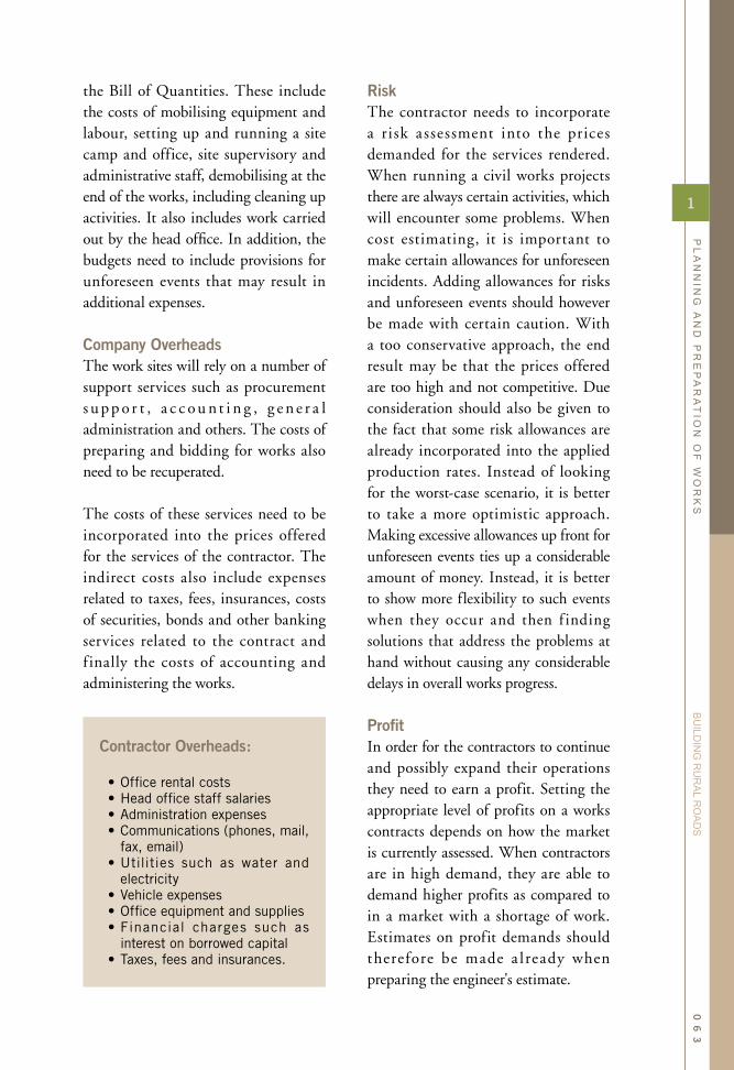
the Bill of Quantities. These include the costs of mobilising equipment and labour, setting up and running a site camp and office, site supervisory and administrative staff, demobilising at the end of the works, including cleaning up activities. It also includes work carried out by the head office. In addition, the budgets need to include provisions for unforeseen events that may result in additional expenses.
Company OverheadsThe work sites will rely on a number of support services such as procurement s u p p o r t , a c c o u n t i n g , g e n e r a l administration and others. The costs of preparing and bidding for works also need to be recuperated.
The costs of these services need to be incorporated into the prices offered for the services of the contractor. The indirect costs also include expenses related to taxes, fees, insurances, costs of securities, bonds and other banking services related to the contract and f inally the costs of accounting and administering the works.
RiskThe contractor needs to incorporate a risk assessment into the prices demanded for the services rendered. When running a civil works projects there are always certain activities, which will encounter some problems. When cost estimating, it is important to make certain allowances for unforeseen incidents. Adding allowances for risks and unforeseen events should however be made with certain caution. With a too conservative approach, the end result may be that the prices offered are too high and not competitive. Due consideration should also be given to the fact that some risk allowances are already incorporated into the applied production rates. Instead of looking for the worst-case scenario, it is better to take a more optimistic approach. Making excessive allowances up front for unforeseen events ties up a considerable amount of money. Instead, it is better to show more flexibility to such events when they occur and then f inding solutions that address the problems at hand without causing any considerable delays in overall works progress.
ProfitIn order for the contractors to continue and possibly expand their operations they need to earn a profit. Setting the appropriate level of profits on a works contracts depends on how the market is currently assessed. When contractors are in high demand, they are able to demand higher profits as compared to in a market with a shortage of work. Estimates on profit demands should therefore be made a lready when preparing the engineer's estimate.
Contractor Overheads:
• Office rental costs• Head office staff salaries• Administration expenses• Communications (phones, mail,
fax, email)• Utilities such as water and
electricity • Vehicle expenses• Office equipment and supplies• Financial charges such as
interest on borrowed capital• Taxes, fees and insurances.
1
PL
AN
NIN
G A
ND
PR
EP
AR
AT
ION
OF
WO
RK
S
BU
ILDIN
G R
UR
AL R
OA
DS
06
3

Calculating Direct CostsThe direct costs are essentially the cost of the construction works, consisting of the cost of labour, materials and equipment required to carry out the work activities. For any considerable amount of works, the direct costs items are normally specified in a Bill of Quantities. The standard estimating procedures for most civil works projects, is that the client first produces a set of estimated quantities of works, to which a estimated cost is calculated. When prices are collected from potential contractors, the contractors need to produce their own cost estimates on the basis of the calculated quantities.
The calculation of direct costs is based on the costs incurred by employing labour, operating or renting equipment and buying the necessary materials. Alternatively, if part of the work is carried out through sub-contractors, it is necessary to estimate the likely costs of relying on such services.
For most civil works, the inputs of materials and equipment usage constitute the majority of the costs. For labour-
based works, the wage component of unit rates also constitutes a significant component of the cost. It is important that the unit rates established when estimating costs are at levels which:
(i) cover all costs relating to materials inputs, use of equipment and labour costs,
(ii) are sufficient to provide for current labour wages, attractive enough to secure the required recruitment of labour and provide the incentives necessary to achieve good work outputs,
(iii) cost a re ba sed on rea l i s t ic production rates and equipment availability (or down-time),
(iv) for material costs, have been confirmed by suppliers for the prescribed quality specifications.
Works specifications specify how works are carried out. When estimating costs, it is common practice to split the works into detailed activities following the same divisions as found in the standard work specifications. The costs of the construction works will vary according to the methods applied and the level of
1
PL
AN
NIN
G A
ND
PR
EP
AR
AT
ION
OF
WO
RK
S
BU
ILDIN
G R
UR
AL R
OA
DS
06
4

quality required. In order to be clear as to what the estimated costs covers, it is useful to refer to the methods and quality specified in the standard work specifications.
Production RatesEquipment costs are calculated on the basis of usage time or cost per produced unit. When estimating and tendering for works, it is important to differentiate between average production rates and task rates. A production rate is the average performance measured over a longer period of time, preferably over several work projects, including losses of production due to faulty works, disruptions due to bad weather,
equipment failure, etc. Such rates represent an average of the efficiency of sites which have been well organised as well as sites where the work organisation falls short of expectations. In some cases, the average production rates for the purpose of estimating would be 30 to 40 percent lower than the actual task rates set for a specific activity or given to the individual workers.
It is also important to bear in mind the variations of the site conditions depending on when the works takes place. With moderate amounts of rain, task rates can be increased as compared to excavating hard soils in the dry season. During the peak of the rainy season most civil works
1
PL
AN
NIN
G A
ND
PR
EP
AR
AT
ION
OF
WO
RK
S
BU
ILDIN
G R
UR
AL R
OA
DS
06
5
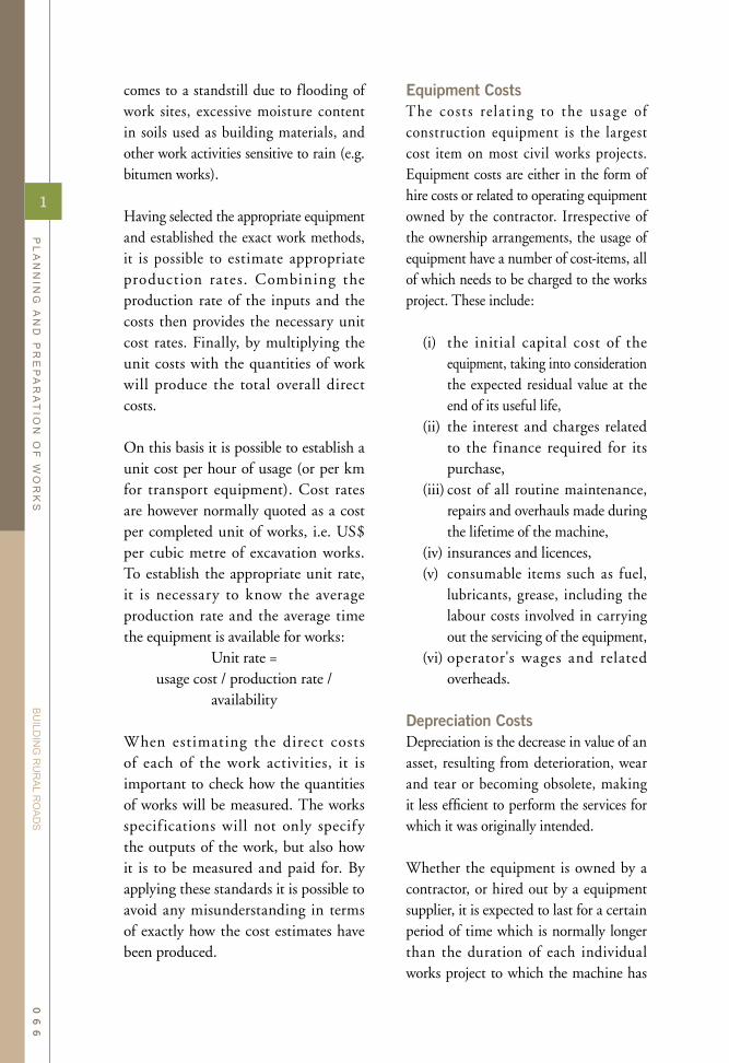
comes to a standstill due to flooding of work sites, excessive moisture content in soils used as building materials, and other work activities sensitive to rain (e.g. bitumen works).
Having selected the appropriate equipment and established the exact work methods, it is possible to estimate appropriate production rates. Combining the production rate of the inputs and the costs then provides the necessary unit cost rates. Finally, by multiplying the unit costs with the quantities of work will produce the total overall direct costs.
On this basis it is possible to establish a unit cost per hour of usage (or per km for transport equipment). Cost rates are however normally quoted as a cost per completed unit of works, i.e. US$ per cubic metre of excavation works. To establish the appropriate unit rate, it is necessary to know the average production rate and the average time the equipment is available for works:
Unit rate = usage cost / production rate /
availability
When estimating the direct costs of each of the work activities, it is important to check how the quantities of works will be measured. The works specif ications will not only specify the outputs of the work, but also how it is to be measured and paid for. By applying these standards it is possible to avoid any misunderstanding in terms of exactly how the cost estimates have been produced.
Equipment CostsThe cost s re lat ing to the usage of construction equipment is the largest cost item on most civil works projects. Equipment costs are either in the form of hire costs or related to operating equipment owned by the contractor. Irrespective of the ownership arrangements, the usage of equipment have a number of cost-items, all of which needs to be charged to the works project. These include:
(i) the initial capital cost of the equipment, taking into consideration the expected residual value at the end of its useful life,
(ii) the interest and charges related to the finance required for its purchase,
(iii) cost of all routine maintenance, repairs and overhauls made during the lifetime of the machine,
(iv) insurances and licences,(v) consumable items such as fuel,
lubricants, grease, including the labour costs involved in carrying out the servicing of the equipment,
(vi) operator's wages and related overheads.
Depreciation CostsDepreciation is the decrease in value of an asset, resulting from deterioration, wear and tear or becoming obsolete, making it less efficient to perform the services for which it was originally intended.
Whether the equipment is owned by a contractor, or hired out by a equipment supplier, it is expected to last for a certain period of time which is normally longer than the duration of each individual works project to which the machine has
1
PL
AN
NIN
G A
ND
PR
EP
AR
AT
ION
OF
WO
RK
S
BU
ILDIN
G R
UR
AL R
OA
DS
06
6

been assigned. The cost of purchasing the equipment therefore needs to be distributed to the various projects where it is used. By the time the equipment is worn out, the owner needs to have recuperated the expenses of not only operating the equipment but also the initial purchase amount.
All equipment has a f ixed lifetime
during which it can be effectively used for carrying out civil works. Eventually it wears out and at a certain point of time it becomes too old or obsolete and needs to be replaced. Depreciation of its value is a method of distributing the costs of the equipment investments to the various projects where it is being utilised during its useful life.
Equipment Depreciation
FThe simplest method is to distribute the depreciation costs evenly over the lifetime of the equipment. This implies that the value of the equipment decreases in time at a uniform rate. The annual depreciation can then be found by dividing the purchase cost, less the salvage value, by the estimated life of the equipment. For example, if a roller, costing US$8,000 is estimated to last 5 years at which time the scrap value is around US$ 500:-, the annual depreciation would be 1,500:-. Assuming that the roller will be operating 150 days per year and will effectively be available 5 hours each day, the hourly depreciation cost will be 1,500 / 150 / 5 = 2.00 US$/hour.
For less costly equipment, this quick method of calculating depreciation costs may be sufficient. For more expensive equipment, and par ticula r ly fo r equipment with considerable repair costs it may be more appropriate to increase the rate of depreciation during the early years. Ideally, the rate of depreciation should be adjusted so that it is possible to achieve a constant operating cost for the use of the equipment during its entire lifetime. This can be achieved if the rate of depreciation can be reduced when the equipment gets older and the costs of maintenance and repairs increase.
In order to achieve this, it is however, necessary to have a good picture of the maintenance and repair costs. As this is
not always the case, equipment owners will still want to write off a considerable portion of the equipment value during its early years as the increase in repair costs are inevitable. A common method of doing this is by applying the sum-of-the-years-digits method. For a piece of equipment with an estimated life of 5 years, the sum of the digits would be 1+2+3+4+5=15. During the first year the equipment will then be depreciated by 5/15 of its purchase value, the second year by 4/15, the third by 3/15 and so on. In effect this leads to a 33 percent depreciation in the first year, 27 percent in the second year, 20 percent in the third year and eventually only 7 percent in the final year.
There are more sophisticated models available, however, considering the variations in all the variables and parameters involved, the general approach of frontloading the depreciation to the extent possible without overcharging for the equipment is a common approach used in construction industry.
1
PL
AN
NIN
G A
ND
PR
EP
AR
AT
ION
OF
WO
RK
S
BU
ILDIN
G R
UR
AL R
OA
DS
06
7

There a re a number of methods that can be used to ca lculate the depreciation costs of equipment. The chosen method is often dictated by external factors and the purpose of the calculations. Depreciation of assets forms an essential part of company accounting and tax authorities will have clear rules on how this is carried out. When attempting to estimate the real costs of the use of equipment, it may be necessary to use different models.
InterestInterest on equipment investments is essentially the opportunity cost of investing in equipment rather than placing the money in an interest accruing account. This may sound r a t her t heore t ic a l , however, in equipment leasing schemes this item appears as a real cost, in the form of the charges for the leasing services.
Repairs and Maintenance CostsRegular repair and maintenance is necessary in order to secure a decent availability rate and performance from the equipment. The repair costs will increase over time. Eventually these repairs become so frequent and expensive that it is no longer worthwhile keeping the equipment. This time is referred to as the end of the useful life of the equipment.
The equipment will need regular supply of fuel and lubricants. Finally, it is common practice to include the costs of employing a driver for the equipment as part of the total equipment costs.
MaterialsMaterials are a major cost item on building works, including structures in road works projects. The main material items in relation to road works are the inputs used for concrete and masonry structures, such as cement, reinforcement steel and aggregate. In addit ion, materials costs occur in a significant manner when the road is provided with a bitumen-based pavement.
The amount of materials required is calculated from the technical drawings. Volumes of concrete are obtained from the physical dimensions of the structures. Reinforcement steel can be summed up from the structural designs. The proportions of cement and aggregate in the concrete provide the necessary basis for calculating the amount of each ingredient. Similarly, the prescribed composition of the pavements will indicate the volumes of bitumen and aggregate.
When assembling prices on materials it is important to clarify whether the rates given include the costs of transport to site. Building materials are heavy and bulky and therefore the costs of delivery may be significant.
Equally, the estimates need to include costs of form works and scaffolding. Finally, it is important to factor in a certain amount of spillage in the material quantities.
When estimating material costs, it may also be necessary to consider possible price increases of materials and wages during the course of the contract. Some
1
PL
AN
NIN
G A
ND
PR
EP
AR
AT
ION
OF
WO
RK
S
BU
ILDIN
G R
UR
AL R
OA
DS
06
8

contracts have separate clauses that spells out how such additional costs can be added to a project. At the early stages of estimating a new project, it may be useful to add some provisions for cost increases. If the project is expected to start in the immediate future and is of a short duration, such provisions are not included.
LabourThe cost of labour is often a minor factor in conventional building and civil works projects. When applying labour-based works methods, however, it is possible to substitute some of the equipment usage with labour. For rural road construction or improvement works, the labour costs component can then be increased to roughly a third of the total costs (with
the remaining two thirds distributed on equipment and materials).
Assembling the Price DataProducing a reliable cost estimate requires the involvement of a number of key players and resource persons. Information relat ing to prices on materials, equipment and services need to be up to date. To achieve this, it is necessary to consult the right technical staff, material suppliers and contractors. Large contracting firms have dedicated staff dealing with estimating and pricing of works. Equally, central road works agencies often prepare cost norms used for preparing estimates of new works projects. Still, the best reference source for costing new projects is the costs incurred on recent or on-going works.
1
PL
AN
NIN
G A
ND
PR
EP
AR
AT
ION
OF
WO
RK
S
BU
ILDIN
G R
UR
AL R
OA
DS
06
9

1.14 Tendering Stage
The purpose of this stage is to identify and engage the best suitable contracting firm(s) to carry out the planned works. The selection of contractors needs to be carried out according to the procurement rules and regulations set by the government. In addition, it also needs to be perceived by the competing firms as fair and transparent, providing all qualif ied participants with equal opportunity when competing for the job.
Similar to the design stage, the bidding stage needs to be carefully planned. Producing a detailed procurement schedule is useful for all participants involved in the bidding process.
As mentioned earlier, the client is always eager to commence construction works as soon as possible, so the various bidding activities need to be scheduled in detail clearly indicating when each individual involved will need to be available and when their inputs need to be completed.
Decision to BidFor all contractors the most important issue determining whether to participate in a bid competition is the potential for profit on a particular works project. Preparing and submitting bid proposals costs money so the contractor needs to be selective in terms of choosing the right projects where there is a good chance of winning a tender and thereafter making a profit on carrying out the works. There is obviously a close relationship between the mark-up and the chance of winning a bid. Increasing the mark-up will reduce the success rate.
In addition to assessing the chances of winning the tender, there are other issues which need careful consideration. A central issue at the very start of the tendering process relates to knowledge of the actors in the construction industry. Contractors want to carry out the bulk of their works with reliable clients, with which they have already established good working relationships. Commencing works for new clients always bears certain uncertainties. These can be questions relating to
1
PL
AN
NIN
G A
ND
PR
EP
AR
AT
ION
OF
WO
RK
S
BU
ILDIN
G R
UR
AL R
OA
DS
07
0

the timeliness of payments, quality of supervision, quality control measures, etc. Equally, the source of funding may indicate the ability of the client to pay for the works on time.
From the client's point of view, it is also preferable to work with known contractors with a past record of timeliness and good quality work. These comfortable relationships also need to be weighed up against the need for securing competitive prices for the works. Attracting new contractors to participate in the tenders allows for more competition and possibly better prices. Providing market access to new contractors may also stimulate growth in the industry thereby improving the implementation capacity.
Type, Size and Location of WorkThe project location has a major impact on who will bid for works and will in most cases favour the local contractors already established in the vicinity of the works. For smaller works, there is also the issue of whether the mobilisation costs become too high in comparison to the overall size of the works. These are important issues when the works are packaged into contracts. Offering larger contract packages may attract
bidders from far away, however, it may disqualify some of the local small firms.
The decision whether to attract local or outside f irms is also determined by the contents of the works and the prof iciency and experience of local contractors. If the required skills and experience are not available among local contractors, efforts are necessary to secure the interest of firms from far away to come and work in the area where the works are located. Organising the contracts into larger packages will encourage bidders from far away to tender for the works.
Contractors need a steady supply of work in order to sustain their operations. For this reason the decision to bid wil l be determined by the envisaged workload at the time when the works commence. Even with full order books, the contractor may still want to tender for the works, relying on sub-contractors and rented equipment. This however, involves more risks as the increased works may stretch the capacity of the overall management of the firm. Equally, by relying on hired equipment and the performance of sub-contractors will add more uncertainties to the works.
1
PL
AN
NIN
G A
ND
PR
EP
AR
AT
ION
OF
WO
RK
S
BU
ILDIN
G R
UR
AL R
OA
DS
07
1

1.15 Works Implementation
Short Term PlansShort-term plans are used for the systematic planning of physical works activities at site level. A central part of this exercise is to establish short-term targets for all major work activities with the resources available on site.
Although planned targets are not always met, it is still the aim of the project management to achieve the long-term goals and deadlines. This means changes and adjustments are made to the short term plans when necessary. To enable managers to put progress back on target if production slips, it is important that there is accurate monitoring of progress and the flexibility to take new decisions when and as required.
The construction supervisors have to plan in detail how the workforce and equipment is to be organised in order to reach the set targets. This planning is called daily work planning.
Daily Work PlanningThe Daily Work Plan is the most detailed of the plans. It outlines which activities will be executed, how many workers and machines allocated to each activity and the quantity of work resulting from these inputs.
The supervisors must always plan ahead by at least one day. At the end of the workday, the supervisor records the outputs achieved on each of the activities. Based on the production achieved and the plan outputs, a plan
for the following day is prepared, s e t t i n g n e w daily production targets for each of the planned activities.
To prepare these work plans properly, the supervisor needs to know what has happened on the site before. Without information such as the resources that were needed to produce a given output, why certain targets were not met, etc., proper planning is impossible. To get the right information on time, a well functioning reporting system is required.
The basis for the daily work plan is:
(i) the measured quantities of work for the major construction activities,
(ii) estimated productivity (task) rates,(iii) the resources (labour, equipment
and materials) available and allocated to each activity.
The planned and achieved outputs are recorded together with the inputs of labour and equipment on a daily basis. Using a standardised form as shown below allows for the comparison of results between several sites. At the end of each week and month the results are compiled and plotted against the overall project plan.
Taking Remedial ActionVe r y o f t e n , p l a n s h a v e t o b e changed, before or during the works implementation, due to such factors as changes in the number of workers available, equipment breakdown, bad
1
PL
AN
NIN
G A
ND
PR
EP
AR
AT
ION
OF
WO
RK
S
BU
ILDIN
G R
UR
AL R
OA
DS
07
2

of management involved in the monitoring process:
• at site level, targets are monitored in detail for each individual activity. In addition, it is common practice to maintain detailed records of all labour, material and equipment inputs,
• a district or sub-district office w i l l n o r m a l l y c o m p i l e a summary of planned outputs and compare these to actual progress,
• at provincial level, targets per district would be established and monitored, and
• at headquarters, the national and overall programme targets are set and monitored.
To be able to set targets, the following information must be known:
• the technical standards to be achieved,
• the quality standards to be achieved,
weather or unforeseen difficulties such as bad soils or hidden rock. This means that the supervisor must be alert and anticipate such changes to the best of his/her ability and adapt the plans accordingly.
It is important to note why certain changes in the plan had to be made. When, for example, the work had to be re-planned because of insufficient tools or materials, this means that the stocking of the site store is inadequate and needs to be improved.
Construction TargetsThe set t ing of construct ion and productivity targets is essential for project monitoring. The comparison between planned targets and actual achievement allows for a realistic judgement of the performance of a work unit or site. Targets must not only be set for outputs in terms of quantities, but also in terms of quality.
The degree of details in targeted outputs varies according to the level
1
PL
AN
NIN
G A
ND
PR
EP
AR
AT
ION
OF
WO
RK
S
BU
ILDIN
G R
UR
AL R
OA
DS
07
3

• the quantity and difficulty of the work,
• current task and productivity rates, and
• resources required and available (labour, materials and equipment, etc.).
However, there are other factors that influence productivity and operational plans. Some of these are beyond the control of the management, but must be allowed for, such as adverse weather conditions, unforeseen soil conditions, disruptions in supplies of goods and materials.
Once targets have been established, the planners can calculate the cost ceilings and prepare budgets. Work plans may also have to be revised in line with availability of funds. Most programmes will have an overall plan, describing how to achieve f ina l programme objectives, and annual plans to plan the work over a financial year.
1
PL
AN
NIN
G A
ND
PR
EP
AR
AT
ION
OF
WO
RK
S
BU
ILDIN
G R
UR
AL R
OA
DS
07
4

S U R V E Y I N G A N D S E T T I N G O U T
CHAPTER 2

SURVEYING
When planning the construction of a new road, there are always several pos s ible choice s of a l ignment s . Although the shortest connection between two points is a straight line, the road alignment is seldom entirely straight. There are a number of reasons for this:
(i) a straight and short alignment would cut through villages, farms or other public or private property. In most cases, this is not acceptable, as it would destroy crops, buildings and public facilities;
(ii) in hilly or mountainous terrain, the resulting gradients on a st ra ight a l ignment become too steep and the required earthworks will be excessive;
(iii) a straight alignment may pass through difficult terrain such as rocks, swamps, dense forest, etc., which should be avoided to minimize construction costs;
(iv) if a river or other obstacle has to be crossed, it is necessary to establish an alignment which provides a crossing at the most suitable location;
(v) by choosing a slightly longer a l ignment, the road can be constructed on soils more suitable for road building purposes;
(vi) A more circuitous route may allow the road to provide access to a greater number of people
(vii) Finally, the choice of alignment may be influenced by the location of suitable sources of water and the location of gravel deposits.
2.1 Selecting the Road Alignment
AND SETTING OUT2
SU
RV
EY
ING
AN
D S
ET
TIN
G O
UT
BU
ILDIN
G R
UR
AL R
OA
DS
07
6

Rural roads are built to improve access and will usually not have stringent requirements in regards to road curvature. Prior to the construction of the road, the community has most probably been relying on a track or a trail. Following the alignment of existing tracks will in most cases have the least effect on the surrounding environment. Often, the alignment of existing tracks also provides the best solution in terms of reducing the amount of earthworks.
It is sensible to make sure that all interested parties agree on the route and places to be linked by a new or improved road. During the early planning stages, it is therefore useful to carry out a process of consultation with the communities and beneficiaries of the road works project.
Factors Affecting Choice of RouteAn alignment with steep gradients may initially be cheaper than selecting a longer route avoiding steep sections and thereby reducing the road gradient.
Road sections with steep gradients however require more maintenance and are therefore more expensive to operate in the long run as compared with roads with gentle gradients.
Costs to future traff ic are greater when the road is designed with steep gradients. More energy is used to climb and descend steep hills, causing more wear to the vehicles. More powerful means of transport are required for steep curvatures. Animal drawn carts will only be able carry reduce loads on such roads.
Vertical alignments requiring excessive cuts and fills along the road line should be avoided. By adjusting the horizontal a lignment to the existing terrain, there is a large potential for reducing earthworks. Avoiding large side cuts also reduces the risk of soil erosion and landslides.
Equally, steep side-sloping ground should be avoided even if the existing road or track is cut into it. If possible, relocate the line lower down the hillside where the ground is flatter.
The higher construction costs of a longer alignment may also be justified if the road can provide additional access to public facilities such as schools, clinics and community centres. While close proximity to the road is regarded as an advantage, road safety concerns may argue for a road alignment at a safe distance from residential areas, schools and other public facilities.
The road planning team also needs
Check List
• Locate the best sites for river crossings,
• Avoid rocky areas• Avoid areas with heavy bush
clearing• Try to avoid areas requiring
complicated drainage solutions• Follow existing alignments • Avoid steep gradients (max
10%)• Keep earth moving to a minimum• Be considerate with existing
farming activities in the area• Avoid triggering soil erosion
2
SU
RV
EY
ING
AN
D S
ET
TIN
G O
UT
BU
ILDIN
G R
UR
AL R
OA
DS
07
7

2
SU
RV
EY
ING
AN
D S
ET
TIN
G O
UT
BU
ILDIN
G R
UR
AL R
OA
DS
07
8

to consider existing land use and to whom the land belongs. Although compensation arrangements can be made, careful consideration of all possible alternatives at the design stage may avoid such issues or at least reduce encroachment on private property to a level at which it does not cause serious impact on the livelihood of local residents.
Cross drainage structures are expensive and can to a certain extent be avoided when the road follows the line of the watershed. High ground such as watershed borders has natural drainage and if the road is located in such terrain, the amount of drainage works is significantly reduced.
Initial SurveyThe objective of the preliminary survey is to obtain a general idea of the future location and dimensions of the road and to assess how this alignment integrates into the surrounding environment. This relates particularly to the existing terrain as well as the impact of the road on local residents and their economic activit ies. By considering severa l alternative alignments, it is possible to arrive at a final solution that to the extent possible takes all these aspects into consideration. The survey methods used at this stage can therefore be simplified without prejudicing the level of accuracy desired.
The centre l ine of a new road is e s t ab l i shed we l l i n adva nc e of commencing construction works. This allows the authorities sufficient lead-time to resolve any right-of-
way issues with local residents and to ensure that no new economic activities commence inside the road reserve, i.e. new buildings erected, planting new crops, etc. It also allows local residents reasonable time to terminate on-going farming or other economic activities within the road reserve before the road works commence.
The initial survey is an essential input for the preliminary cost estimates and budget allocations. From the survey, rough quantit ies of work can be derived, soil conditions observed and productivity norms and costs assumed. This survey also provides an overview of potential social and environmental impacts caused by the new road alignment. The line established by the surveyor is clearly defined and marked properly so that it can be retraced during the detailed design.
It is important to stress that during this survey the subsequent end product must be borne in mind. When building a new road for local traffic, expected to
2
SU
RV
EY
ING
AN
D S
ET
TIN
G O
UT
BU
ILDIN
G R
UR
AL R
OA
DS
07
9

carry limited traffic volumes, the choice of alignment should reflect this. A high-speed alignment and design is expensive and irrelevant to a low volume rural road. Undulating vertical curvature and comparatively sharp curves are more compatible with local roads with limited traffic.
Detailed SurveyPreceding road construction and the bidding process, a supplementary survey is undertaken. The purpose of the detailed survey is to establish all the details of the chosen alignment such as the exact location, width and levels of the road and drainage arrangements. On this basis, the precise quantities of works are estimated and used as the basis for further planning and preparation of works.
Setting Out WorksSurveying activities are carried out at various stages of a civi l works project, starting at the planning stage,
throughout the construction stage and once more during the final stage of measurement of completed work for payments. For this reason, it is useful to establish a dedicated setting out team, which deals with all surveying activities throughout the duration of the project.
Setting out works is a daily activity on which all other works operations rely in order to achieve good quality outputs. Equipment operators and work gangs need directions on where, and to which dimensions works are to be carried out. Supervisors need to ensure that individual work tasks have been properly defined in order to organise the works efficiently.
In order to meet these daily requirements in terms of def ining work s, it i s important to establish efficient setting out work methods and procedures, which at the same time provide the prescribed level of accuracy.
2
SU
RV
EY
ING
AN
D S
ET
TIN
G O
UT
BU
ILDIN
G R
UR
AL R
OA
DS
08
0

There are a number of appropriate methods for setting out a road alignment. The choice of surveying equipment is based on the required level of accuracy and the applied setting out methods. When survey ing rura l roads, it i s important to bear in mind the required level of accuracy for the works. Obviously, the level of detail for a rural road is not the same as for major highways or city streets.
Bearing this in mind, the following section describes some low-cost and easy to use but still sufficiently accurate methods of surveying and setting out rural road work.
Reference pegs are used to mark the alignment and road levels. They are invariably of wood, tree branches or stakes cut to length, ideally 40 cm long and 5 cm diameter or 5
cm x 5 cm square. It is useful to paint them white or yellow to improve their visibility. The chainage is painted on a prepared surface on the peg. To avoid loss or damage, these pegs are placed outside the road width, hammered deep into the ground to avoid pilferage and placed in a prominent location.
Survey pegs are used for locating the various parts of the road, such as the centre line, road shoulders, side drains, culvert trenches, etc. Pegs are also used for marking the daily task work of each individual worker. The pegs are sharpened sticks 30 cm long, manufactured on site. Together with a string line, they are also used for defining vertical levels when carrying out earth fills or levelling works.
Tape measures are available in a large variety of shapes and lengths. The most common lengths used for setting out are 30m and 5m. The tapes are made
2.2 Tools for Surveying and Setting Out
2
SU
RV
EY
ING
AN
D S
ET
TIN
G O
UT
BU
ILDIN
G R
UR
AL R
OA
DS
08
1

of steel or linen. Although the former is stronger, the numbers and marking on the tape becomes unreadable after a period of use. Tapes are vital for setting out lengths and widths as well as setting
tasks and measuring completed works.The smaller tapes, 2m, 3m or 5m in length, are useful for small construction elements, such as profiles of ditches, cambers, trenches, etc. It is important to keep them clean and avoid dirt entering the case.
Profile Boards are used to determine the vertical alignment of a road section. The profile board is designed in such a
way that it can be attached to a ranging rod. It has a screw mechanism that enables the profile board to slide up and down the ranging rod and be fixed at any desired level by tightening the screw.
A long-lasting profile board is made from thin steel plate welded to a short length of metal tubing that can slide up and down and be clamped to the ranging rod. A useful size for the metal profile board has been found to be 40cm by 12cm. It is painted red to make it easy to see.
Ranging Rods are used to set out stra ight and curved l ines and to support profile boards when setting out the vertical alignment of the road. Ranging rods can be made from hollow metal tubes, such as 20 - 25mm diameter galvanized water pipes, with a pointed end made from sharpened reinforcement steel. They are normally 2 metres long, and are painted red and white to make them easy to see during setting out.
Both profile boards and ranging rods are inexpensive and can easily be manufactured by a local metal work business.
Before commencing setting out works, make sure that a suff icient amount of ranging rods and profile boards is
2
SU
RV
EY
ING
AN
D S
ET
TIN
G O
UT
BU
ILDIN
G R
UR
AL R
OA
DS
08
2

available. A supply of 20 rods and profile boards is regarded as a minimum to effectively carry out the job.
In very compact, or rocky ground, it may be necessary to first make a hole for the ranging rod by hammering down a metal spike made of high tensile reinforcement steel. Crowbars can also be used for this purpose.
A useful additional tool is a sliding hammer with a weighted head that fits over the ranging rod and can be used to drive the ranging rod into the ground.
Line LevelsThe level of the profile boards can be controlled by using a line level. The line level is a short spirit level (about 100 mm long) with a hook at each end to hang it from a nylon string.
This instrument needs two persons to operate - one at the end of the line, and
the second to watch the spirit level. The line operator moves the string up or down until the bubble is centred in the middle between the spirit level marks. The string line will then indicate the horizontal line.
For this purpose a clear nylon fishing line should be used. This makes it easy to move the level along the line to the required position.
The line level has a range of up to about 50 metres. It is easy to carry around, and with care it can be used for setting out levels and slopes not less than 1 in 300.
Points to remember when using a line level:
• The line level should be placed ha l f way bet ween the t wo ranging rods. Use a measuring tape to f ind the exact middle point.
• Keep the string tight - do not let it sag.
transfer the exact level from one profile board to another profile, thereby ensuring that both are at the same level,
measure up or down from a known horizontal level, and set a new level, and
find the slope between two fixed profile boards, and determine which one is higher.
The line level can be used to:
2
SU
RV
EY
ING
AN
D S
ET
TIN
G O
UT
BU
ILDIN
G R
UR
AL R
OA
DS
08
3

• The l ine level i s a del icate instrument, look after it - do not throw it around and treat it roughly.
• Check the accuracy of the line level regularly.
Checking the Line LevelLike all surveying equipment, the line level needs to be checked for its accuracy on a regular basis. This can be done by carrying out the following procedure:
• Place two ranging rods 10 metres apart. Fix a line on the one metre mark on one rod, transfer this level to the other rod and mark it.
• While keeping the string in the same position on the first rod, take the line level and turn it around on the string.
• Adjust the string on the second rod until the bubble is in the middle again and mark the new level.
• Check to see if the two marks are at the same place. If not, measure the difference between the two marks.
• If the difference between the
two marks is less than 10cm, the correct level is exactly in the middle of the two marks. If the difference is more than 10cm, the line level is no longer accurate enough and should be replaced.
It is always useful to turn the line level around every time it is used, and take the middle of the two marks as the horizontal level.
Boning rods are generally manufactured on site from wooden laths to a " T " profile and of uniform height. A simple stand can also be manufactured. This version is also referred to as a traveller.
They are used to establish additional levels between f ixed levels (inter-polation) or beyond (extra-polation).
2
SU
RV
EY
ING
AN
D S
ET
TIN
G O
UT
BU
ILDIN
G R
UR
AL R
OA
DS
08
4

They are particularly useful to check gradients of ditches and culverts. In the figure below, it can be seen that the ground level at point 3 is lower than at the locations 1 and 2. By raising the middle boning rod, the bottom end of this rod will indicate the required level in order to achieve a continuous gradient between points 1 and 2.
The same exercise can be carried out using profile boards. Often, a single boning rod is then used to check the surface levels between profile boards. This exercise is commonly applied to secure the correct levels of earthworks layers when building up fills or when spreading gravel.
TrianglesTriangle sets can be manufactured by a carpenter and are used for various purposes:
• to set out a right angle to the centre line (necessary when cross-sections are set out), or
• to c ont ro l or e s t i mate t he steepness of gradients - in this case a spirit level or a plumb line is also required.
The steepness of gradients is described as a ratio. For example, a gradient of 1 : 2 means that over a horizontal stretch of two metres, the terrain will rise one metre vertically. Alternatively, the gradient can be expressed as a
2
SU
RV
EY
ING
AN
D S
ET
TIN
G O
UT
BU
ILDIN
G R
UR
AL R
OA
DS
08
5

percentage increase in elevation. A 6 percent gradient would describe a 6m rise over a 100m horizontal stretch.
When measuring existing gradients using a triangle, a spirit level is required to secure the horizontal line. The joints of the triangle are then adjustable with pinned joints rather than fixed.
The most common use of the triangle is to quickly establish a right angle to the road centre line.
Optical SquareThe optical square is a small instrument using either mirrors or a prism to establish a right angle, as illustrated in the figure below.
Whilst holding the optical square, the observer can see both point B, through a narrow opening in the optical square, and point C through a mirror or prism. When ranging rods are placed at positions B and C, the observer will see ranging rod B directly and ranging rod C reflected as illustrated in the figure above.
When points A and B on the survey line are known and point C has to be found, as shown in the figure below, the person holding ranging rod C
moves forwards or backwards until the observer sees the reflection of rod C in one line with the direct view of rod B. At this point, the angle CAB, is at a right angle.
Straight EdgeThe straight edge is a simple beam, usua l ly made of wood, which in combination with a spirit level and tape measure, can be used to establish a gradient or road camber.
The straight edge is usually 3 metres long and set horizonta l ly with a spirit level. This method is used for
2
SU
RV
EY
ING
AN
D S
ET
TIN
G O
UT
BU
ILDIN
G R
UR
AL R
OA
DS
08
6

the measurement of gradients which continue only for short distances, e.g. culvert beds, drain slopes and road camber. The figure above shows how a gradient of 1:15 is measured.
Tube Water LevelThe use of a "tube water level" is a very accurate and simple method for measuring the level differences of two points.
This level consists of a length of clear plastic hose attached at each end to a wooden levelling staff, as shown in the figure below. The two levelling staffs should be of the same length, about 1.5 m long. A graduated tape is attached to each staff, with the zero level at the top
end of the staff. The tube is filled with water until the level is about one metre high from the ground. Both ends of the tube are fitted with rubber stoppers to prevent loss of water. The total length of the tube, which defines the range of the instrument, is variable, but is usually limited to about 15 m by the difficulty of moving the level around.
The two ends of the pipe are brought together at the starting point, the stoppers removed and the readings taken level with the bottom of each meniscus. The readings should be the same (e.g. reading A = 50 cm, reading B = 50 cm). The surveyor takes the pipe to the point being measured and takes another reading. The difference between the two readings is the
2
SU
RV
EY
ING
AN
D S
ET
TIN
G O
UT
BU
ILDIN
G R
UR
AL R
OA
DS
08
7

difference in level (e.g. if reading A = 30 cm and reading B = 70 cm, the difference in level is then 70 – 30 = 40 cm).
The range is l imited only by the convenience of being able to carry the hose. The two points where the difference in level is being measured do not need to be in sight of one another. The level gives accurate results and can be used for setting level lines or slopes not less than 1 in 1,000.
Dumpy LevelThe dumpy level is a survey instrument c on s i s t i n g o f a telescope fixed to a horizontally rotating table and a spirit level. Mounted on a tripod, it is used to measure height differences, used in combination with a levelling staff. The dumpy level is the classic instrument used for setting out levels in road works projects. Levels can be transferred from a benchmark and new levels can be established
very accurately over distances up to 100 meters. There are several types of dumpy levels on the market, each with its own design.
Camber BoardsA camber board can be used to check the cross slope of the road. Its length is usually the same as the distance from the centre line to the shoulder of the road. In cases where the shoulders have the same gradient as the running surface, the length of the camber board can be extended to include the shoulder.
The figure below shows a 2.5 metre long camber board showing a gradient of 5 percent (1:20). The camber board is built with a length and gradient that suits the required profile. The camber board is used in combination with a spirit level as shown below.
Camber boards are useful for checking
2
SU
RV
EY
ING
AN
D S
ET
TIN
G O
UT
BU
ILDIN
G R
UR
AL R
OA
DS
08
8

the cross-slope on exist ing roads however it should not be used when building a new camber. The use of prof ile boards and a line level will provide more accurate results.
Ditch TemplatesThe ditch template is basica l ly a trapezoid, constructed of timber laths or plywood to check the prof ile of ditches, mitre drains, back slopes, etc. The template is constructed to the same shape and measurements as the drain, to provide a quick and easy method for checking excavation works.
Choice of ToolsThe f inal choice of surveying and s e t t i n g ou t t o o l s i s v e r y muc h dependent on the task at hand and the personal preferences of the technical staff in charge of the work site. Various methods of setting out do, however, have different degrees of accuracy. A particular setting out method should only be chosen if it meets the accuracy requirements for the particular work activity.
The table below shows the appropriate quantities of tools required for carrying out the regular setting out activities relating to rural road construction works. As demonstrated in the following sections, surveying and setting out for rural road works can be carried out using fairly simple and inexpensive equ ipment . These quant it ie s a re adequate for a work site involving 300 workers.
Description Quantity
ranging rods 20
profile boards 20
traveller 1
line levels 5
measuring tapes 30m 3
measuring tapes 5m 6
club hammers 2
chisels / metal spikes 3
axes 6
string 200m
pegs 300
2
SU
RV
EY
ING
AN
D S
ET
TIN
G O
UT
BU
ILDIN
G R
UR
AL R
OA
DS
08
9

2.3 Horizontal Alignment
Prior to construction, the exact location of the road needs to be established through a detailed survey. The position of the road centre line provides the main reference for the setting out of all other key positions relating to the various components and structures that form part of the road. While surveying work s for h ighway construct ion normally relies on triangulation and polygon networks and up-to-date maps, surveying for rural road works is normally carried out without such aids. A common approach used to establish the alignment for a rural road is by finding a suitable alignment in the terrain, using simple tools such as ranging rods, profile boards and a line level.
When surveying the alignment, the exact location of the road is established by marking the centre line with pegs located every 20 metres on straight sections and every 5 to 10 metres along curves. A mark is also placed on each of these stakes defining the distance (up or down) to the finished formation level of the road surface.
Setting Out a Straight LineSetting out straight lines is the easiest part of surveying. The straight line can be established by placing ranging rods every 50m to 100m, and by sighting along the rods to ensure that they are placed in line. Between these ranging rods, intermediate points are set out at every 10m. Normally, sections of not more than 50 to 100m are set out at the time. In mountainous terrain, sections of less than 50m may be necessary.
In hilly or rolling terrain, the line of sight between two fixed points may be obscured. The following method can then be used to set out a continuous straight line.
The solution is to find two locations on the hill which meet the following conditions:
• From point A, ranging rods placed at points B and C should be visible, and
• From point D, ranging rods set at points C and B must be visible.
From point A, set out points B and C in a straight line which is roughly heading
2
SU
RV
EY
ING
AN
D S
ET
TIN
G O
UT
BU
ILDIN
G R
UR
AL R
OA
DS
09
0

towards point D. Repeat the exercise from position D and ensure that point C is in line between points D and B. Then go back to position A and move the ranging rod at point B so it is in line between the point A and C. Repeat this procedure until A-B-C and D-C-B are straight lines without the need for further adjustments.
Setting Out CurvesAt f irst, the centre line is def ined by means of a series of straight lines meeting at points of intersection (PI). To avoid abrupt changes of direction in the road alignment, these straights are joined by curves thus creating a more
smooth curvature.
The distance between the intersection points can easily be measured and used as a first estimate of the length of the road to be constructed.
There are various methods to set out curves. With rural roads designed for low traffic volumes, it is usually suff icient to follow existing tracks and to improve existing curves where necessary. Some simple methods to set out curves using a tape measure, ranging rods, pegs and strings are described on the following pages.
B
B
DA
C 2
SU
RV
EY
ING
AN
D S
ET
TIN
G O
UT
BU
ILDIN
G R
UR
AL R
OA
DS
09
1
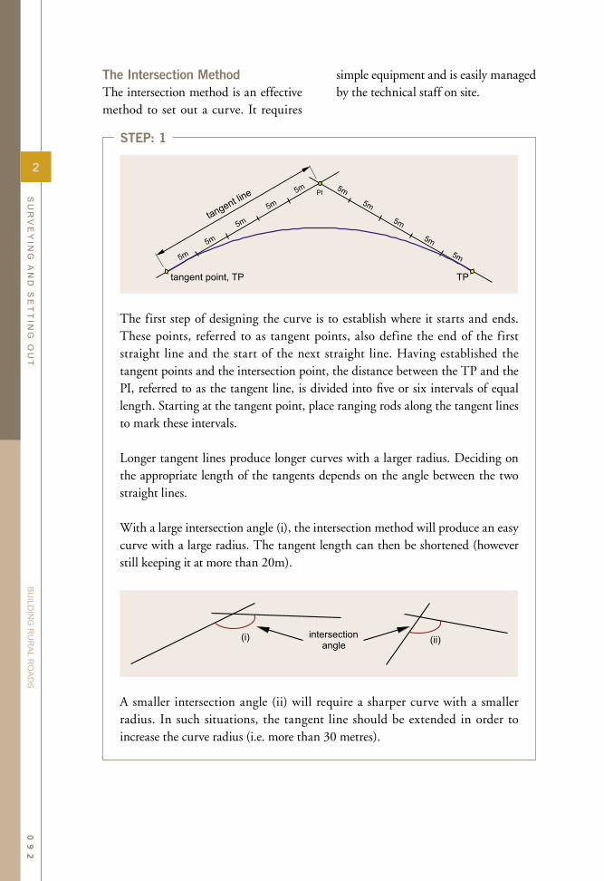
The Intersection MethodThe intersection method is an effective method to set out a curve. It requires
simple equipment and is easily managed by the technical staff on site.
The first step of designing the curve is to establish where it starts and ends. These points, referred to as tangent points, also define the end of the first straight line and the start of the next straight line. Having established the tangent points and the intersection point, the distance between the TP and the PI, referred to as the tangent line, is divided into five or six intervals of equal length. Starting at the tangent point, place ranging rods along the tangent lines to mark these intervals.
Longer tangent lines produce longer curves with a larger radius. Deciding on the appropriate length of the tangents depends on the angle between the two straight lines.
With a large intersection angle (i), the intersection method will produce an easy curve with a large radius. The tangent length can then be shortened (however still keeping it at more than 20m).
A smaller intersection angle (ii) will require a sharper curve with a smaller radius. In such situations, the tangent line should be extended in order to increase the curve radius (i.e. more than 30 metres).
STEP: 1
2
SU
RV
EY
ING
AN
D S
ET
TIN
G O
UT
BU
ILDIN
G R
UR
AL R
OA
DS
09
2

A string line is stretched from the ranging rods in positions a on each of the tangent lines. Another string line is pulled between positions b on both the tangent lines. The point of intersection between each of these string lines will mark the first point defining the curve between the tangent lines.
With practice, the determination of this curve point can be done without the string lines. Sight along line a - a while an assistant holds a ranging rod in your sight line. A second assistant stands at point b and sights along the line b - b. Direct the first assistant along line a - a until he/she also stands on the line b - b. Mark this spot with a ranging rod and a peg.
Now repeat this exercise by sighting along b - b while an assistant is sighting along the line c - c to find the next curve point. Once again the curve point is marked with a peg.
STEP: 2
STEP: 3
2
SU
RV
EY
ING
AN
D S
ET
TIN
G O
UT
BU
ILDIN
G R
UR
AL R
OA
DS
09
3

Adjusting the Position of the CurveIf the length of the tangent lines is increased, the f inal curve will move further away from the intersection point, PI. By manipulating the length of the tangent lines, it is possible to avoid obstacles such as trees, buildings, boulders, etc. when setting out the curve.
There will always be one curve point less than the number of segments into which the tangent length is divided. For example, 6 segments will produce 5 curve points.
Even numbers of segments on the tangent line will give uneven numbers of curve points, and provide a middle curve
point opposite the intersection point, PI. Where the two middle lines intersect is the middle point of the curve (as above with c-c & d-d, and B-b & C-c).
Setting Out Curves "by Eye"When following an existing alignment, it is often sufficient to adjust the centre line pegs "by eye" until they appear to follow a smooth curve. A quick way to control and adjust the setting out of a curve is to line up the first and third peg and measure the off-set of the second peg to this line. Then repeat this exercise by lining up the second and fourth pegs and measuring the off-set to the third peg to this line. The process
Complete the exercise for the remaining lines c - c, d - d, until reaching the intersection point. Finally, use these curve points to set out pegs at intermediate points along the curve at 5 m intervals. Inspect the curve and make sure that all the pegs provide a smooth line.
STEP: 4
2
SU
RV
EY
ING
AN
D S
ET
TIN
G O
UT
BU
ILDIN
G R
UR
AL R
OA
DS
09
4
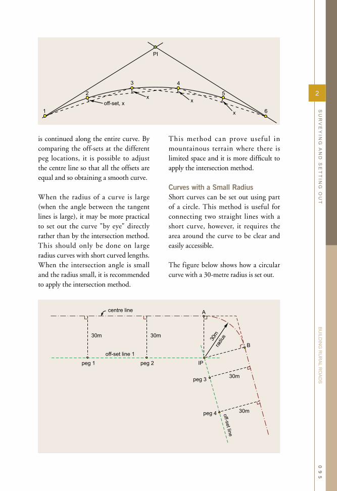
is continued along the entire curve. By comparing the off-sets at the different peg locations, it is possible to adjust the centre line so that all the offsets are equal and so obtaining a smooth curve.
When the radius of a curve is large (when the angle between the tangent lines is large), it may be more practical to set out the curve "by eye" directly rather than by the intersection method. This should only be done on large radius curves with short curved lengths. When the intersection angle is small and the radius small, it is recommended to apply the intersection method.
This method can prove useful in mountainous terrain where there is limited space and it is more difficult to apply the intersection method.
Curves with a Small RadiusShort curves can be set out using part of a circle. This method is useful for connecting two straight lines with a short curve, however, it requires the area around the curve to be clear and easily accessible.
The figure below shows how a circular curve with a 30-metre radius is set out.
2
SU
RV
EY
ING
AN
D S
ET
TIN
G O
UT
BU
ILDIN
G R
UR
AL R
OA
DS
09
5
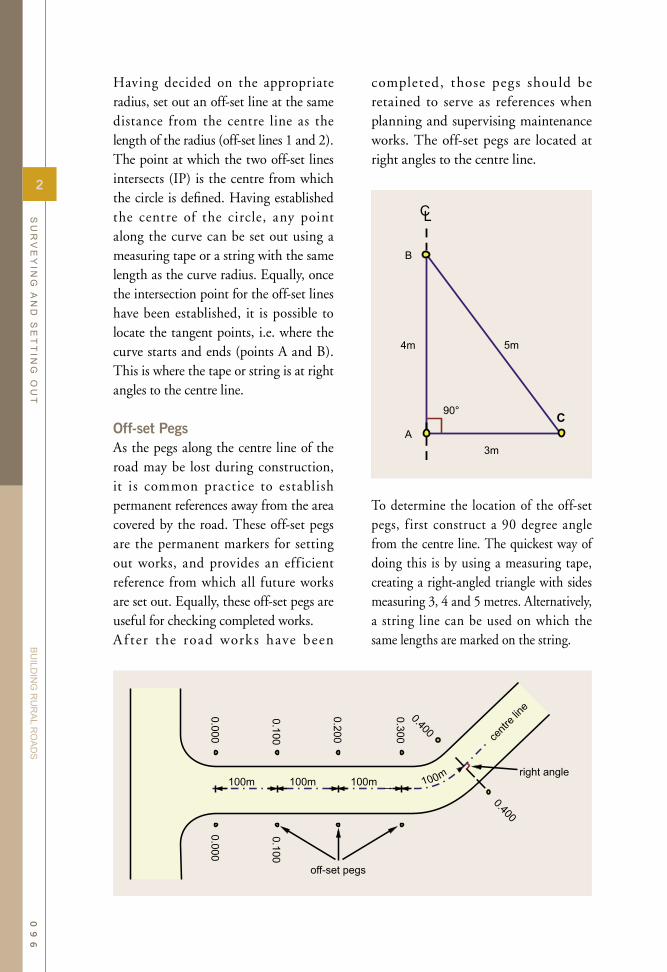
Having decided on the appropriate radius, set out an off-set line at the same distance from the centre line as the length of the radius (off-set lines 1 and 2). The point at which the two off-set lines intersects (IP) is the centre from which the circle is defined. Having established the centre of the circle, any point along the curve can be set out using a measuring tape or a string with the same length as the curve radius. Equally, once the intersection point for the off-set lines have been established, it is possible to locate the tangent points, i.e. where the curve starts and ends (points A and B). This is where the tape or string is at right angles to the centre line.
Off-set PegsAs the pegs along the centre line of the road may be lost during construction, it is common practice to establish permanent references away from the area covered by the road. These off-set pegs are the permanent markers for setting out works, and provides an eff icient reference from which all future works are set out. Equally, these off-set pegs are useful for checking completed works. A f ter the road work s have been
completed, those pegs should be retained to serve as references when planning and supervising maintenance works. The off-set pegs are located at right angles to the centre line.
To determine the location of the off-set pegs, f irst construct a 90 degree angle from the centre line. The quickest way of doing this is by using a measuring tape, creating a right-angled triangle with sides measuring 3, 4 and 5 metres. Alternatively, a string line can be used on which the same lengths are marked on the string.
2
SU
RV
EY
ING
AN
D S
ET
TIN
G O
UT
BU
ILDIN
G R
UR
AL R
OA
DS
09
6
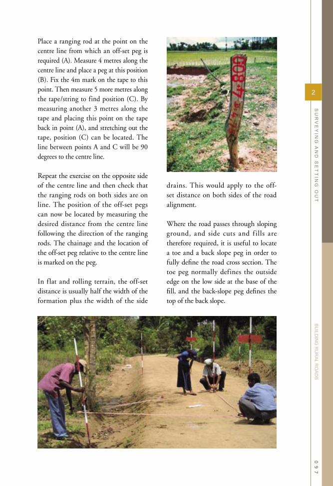
Place a ranging rod at the point on the centre line from which an off-set peg is required (A). Measure 4 metres along the centre line and place a peg at this position (B). Fix the 4m mark on the tape to this point. Then measure 5 more metres along the tape/string to find position (C). By measuring another 3 metres along the tape and placing this point on the tape back in point (A), and stretching out the tape, position (C) can be located. The line between points A and C will be 90 degrees to the centre line.
Repeat the exercise on the opposite side of the centre line and then check that the ranging rods on both sides are on line. The position of the off-set pegs can now be located by measuring the desired distance from the centre line following the direction of the ranging rods. The chainage and the location of the off-set peg relative to the centre line is marked on the peg.
In flat and rolling terrain, the off-set distance is usually half the width of the formation plus the width of the side
drains. This would apply to the off-set distance on both sides of the road alignment.
Where the road passes through sloping ground, and side cuts and f ills are therefore required, it is useful to locate a toe and a back slope peg in order to fully define the road cross section. The toe peg normally defines the outside edge on the low side at the base of the fill, and the back-slope peg defines the top of the back slope.
2
SU
RV
EY
ING
AN
D S
ET
TIN
G O
UT
BU
ILDIN
G R
UR
AL R
OA
DS
09
7

final quality of the road alignment is dependent on a thorough field survey and having made a careful assessment of the various alternatives available.
In f lat or slightly rolling terrain, the design of the vertical alignment is fairly straightforward. The main concern in this type of terrain is to ensure that water is efficiently drained away from the road and that potential floodwater remains well below the road surface levels.
2.4 Vertical Alignment
GeneralThe vertical alignment defines the exact level of the road and how the road is placed in relation to the surrounding ter r a in . A s w it h t he hor i zonta l alignment, most road works agencies have developed appropriate standards for how the vertical alignment is designed. Rules concerning the allowed curvature and gradients greatly inf luence the alignment of the road and the amount of earthworks required. Sti l l, the
2
SU
RV
EY
ING
AN
D S
ET
TIN
G O
UT
BU
ILDIN
G R
UR
AL R
OA
DS
09
8

When the road passes through hilly or mountainous terrain, the choice of alignment is more critical in terms of arriving at a durable design, which stands up to the environment in which it needs to perform. In order to reduce future maintenance works, it is important that the road follows the shape of the existing terrain, avoiding steep gradients and large cuts and fills. Heavy earthworks will often have a detrimental effect on the stability of slopes, and can easily trigger landslides. Side cuts and fills are also more prone to erosion, with the eroded material often falling into the drainage system or causing damage to surrounding areas. It is therefore always recommended to minimise the earthworks by trying to follow the contours of the terrain.
This can often be done in the case of rural roads since the geometrical standards allow for smaller radiuses on the horizontal alignment for such roads. The main purpose of rural roads is to provide basic access. As compared with highways, for which design speeds are a more important design parameter, the main emphasis of rural roads is to maintain all-weather access throughout the year to the rural communities.
Ma x i mu m a l lowable g r ad ient s should not be exceeded except in very exceptional circumstances. Roads with steep longitudinal gradients are exposed to increased erosion from surface water. Experience clearly shows that roads with gradients above 8 percent are difficult to maintain unless a durable pavement is installed on the road surface as well as in the side drains.
Therefore, the option of alternative hor i zonta l a l ignment shou ld be explored to avoid excessive amounts of earthworks and steep gradients. Although this may result in longer alignments, such choices will most probably provide better design solutions as the risk of major damages to the road during the rainy season is reduced.
Several methods can be used for setting out the vertical alignment of rural roads. Similar to the setting out of the horizontal alignment, the methods described in this section rely on the use of string line levels and profile boards.
The Profile Board MethodA commonly used setting out procedure for rural road works is based on the use of a series of profile boards and a string line level. Profile boards are commonly used on all road works projects in order to establish the correct levels for the civil
2
SU
RV
EY
ING
AN
D S
ET
TIN
G O
UT
BU
ILDIN
G R
UR
AL R
OA
DS
09
9

works. The use of a line level provides a simple method of transferring levels from one profile board to another and also measuring the gradient between two profiles. The line level is used as an alternative to a levelling instrument. The method is simple and when used correctly provides sufficient accuracy for rural road works.
This method can be effectively used for setting out most levels on a rural road, including the levels of excavation works and f ills, surface layers and drains. Using profile boards and a line level is also a quick and effective method of establishing the quantities works in the
initial surveys during the planning stage.The basic principle is to place a series of profile boards that show the exact level one metre above the completed construction levels. The method is best described by imagining the excavation of a ditch from point A to point B at the level of the dotted line as shown in the figure below.
To ensure a correct and uniform level of the ditch, ranging rods are placed at positions A and B. Profile boards are
2
SU
RV
EY
ING
AN
D S
ET
TIN
G O
UT
BU
ILDIN
G R
UR
AL R
OA
DS
10
0

mounted on the rods one metre above the level of the excavated ditch.
A third profile board with a fixed height is used for controlling earthworks levels between the two profile boards. It is known as the travelling profile or traveller. A boning rod is effectively used as a traveller. During excavation along the line from points A to B, the traveller can be used to control that the correct levels have been achieved. By placing the traveller in the sight line between A and B, it is easy to determine whether the excavation has been carried out to correct levels.
When the top of the traveller is below the sight line between the two fixed prof ile boards, the ditch has been excavated to a too low level. If the traveller sticks up above the sight line, the ditch needs to be dug deeper.
To provide good guidance, it is useful to dig slots at regular intervals of 4 to 5 metres along the sight line. With
sufficient slots, the workers can start excavating the ditch by removing the soils between the excavated slots. The traveller is then used once again to control that the finished work is to the correct level and that there are no high or low spots.
I f there i s no boning rod readily available, a temporary t ravel ler i s easily made from a ranging road and a profile board by measuring the length needed from the blunt end of a ranging rod to the further edge of the profile. For guiding drainage work, it is, however, more appropriate to use a boning rod with a permanent length, since the profile on a temporary traveller can become loose and thereby indicate an incorrect length.
A traveller is also useful for establishing levels beyond the sightline between to profile boards, as shown in the figure below.
2
SU
RV
EY
ING
AN
D S
ET
TIN
G O
UT
BU
ILDIN
G R
UR
AL R
OA
DS
10
1

When the correct levels have been set out with profile boards, the traveller will give an indication of the finished construction levels anywhere along the sight line.
This is useful for the site supervisor when setting out. The most frequent use of a traveller is to mark levels on setting out pegs. In addition, it can be used for activities, such as:
• to guide and check excavation below earthwork levels (e.g. for excavation works during construction of foundations for structures),
• to find out whether solid rock or large boulders are above or below the level of the road before deciding on the f inal vertical alignment,
• to estimate the amount of fill needed if the level of the road is "lifted", or when the road crosses low areas - this will assist in estimating the quantities of work involved and help decide on the optimal road levels,
• to locate the end of drains and approaches, and
• to provide a quick check on excavated or filled levels.
Vertical LevelsWhen designing the horizontal alignment, it is important to check the gradients along the road. Ideally, the longitudinal gradient should be somewhere between two and eight percent, preferably staying at the low side of the range. In the field, the slope of any surface can easily be established with a line level and two ranging rods. By transferring the level of one profile board to the next ranging rod, the level difference can be determined. The s lope or the grad ient i s then calculated as follows:
If the difference of levels is 0.5m between two profiles with a distance of 20m between them, the gradient is:
This procedure is useful in order to identify low spots along the road line. It is also a useful method for ensuring that the slope of the side drains has the correct gradient and there is no risk of erosion or silting. If the road gradient is found to be unsuitable, the road alignment should be adjusted to produce
2
SU
RV
EY
ING
AN
D S
ET
TIN
G O
UT
BU
ILDIN
G R
UR
AL R
OA
DS
10
2
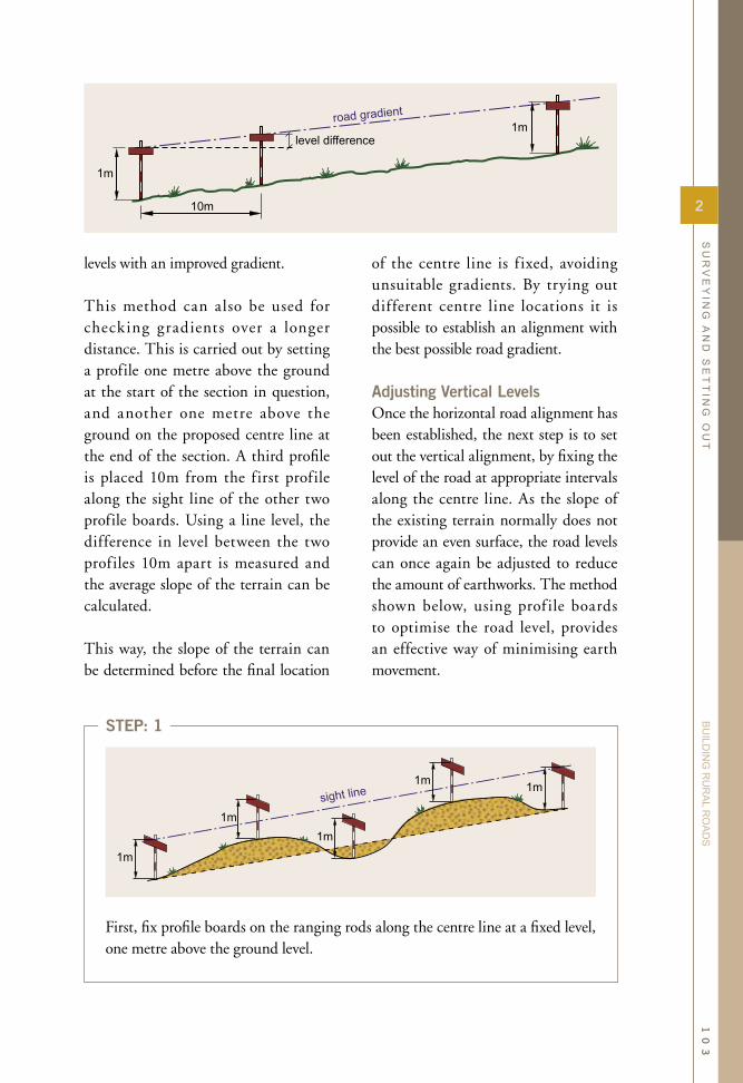
levels with an improved gradient.
This method can also be used for checking gradients over a longer distance. This is carried out by setting a profile one metre above the ground at the start of the section in question, and another one metre above the ground on the proposed centre line at the end of the section. A third profile is placed 10m from the first profile along the sight line of the other two profile boards. Using a line level, the difference in level between the two profiles 10m apart is measured and the average slope of the terrain can be calculated.
This way, the slope of the terrain can be determined before the final location
of the centre line is f ixed, avoiding unsuitable gradients. By trying out different centre line locations it is possible to establish an alignment with the best possible road gradient. Adjusting Vertical LevelsOnce the horizontal road alignment has been established, the next step is to set out the vertical alignment, by fixing the level of the road at appropriate intervals along the centre line. As the slope of the existing terrain normally does not provide an even surface, the road levels can once again be adjusted to reduce the amount of earthworks. The method shown below, using prof ile boards to optimise the road level, provides an effective way of minimising earth movement.
First, fix profile boards on the ranging rods along the centre line at a fixed level, one metre above the ground level.
STEP: 1
2
SU
RV
EY
ING
AN
D S
ET
TIN
G O
UT
BU
ILDIN
G R
UR
AL R
OA
DS
10
3

Then sight along the profile boards. Get an assistant to adjust the level of each of the intermediate profile boards so they are all on line with the first and the last profile. All the profile boards will then be one metre above the completed level of the road.
Where the level of the centre line cuts too deep into the terrain, this will involve excessive excavation work. The profile boards can then be adjusted up or down to reduce the earthworks and also achieving an improved balance between thevolumes of excavation and fill.
Finally, make sure that the profile boards along the centre line have been correctly placed. All other levels for the road structure will be set out based on the profiles along the centre line.
STEP: 2
STEP: 3
STEP: 4
2
SU
RV
EY
ING
AN
D S
ET
TIN
G O
UT
BU
ILDIN
G R
UR
AL R
OA
DS
10
4

• the exact location and amount of excavation works,
• detailed measurements of fills and embankments,
• all road levels including shape of road camber,
• location and shapes of the drainage system, including side and mitre drains, cut-off drains, drifts and culverts, and
• exact location and dimensions of any other structures.
As with the surveying of the road alignment, the setting out of the road cross-section can effectively be carried out using the same surveying tools and methods. The results are marked with pegs, indicating the key locations such as extent and depths of fills and excavations, location and depth of drains, etc.
Setting Out the Road CamberWith the position and levels of the centre line already established, it is possible to set out the camber and side drains. The road camber is usually constructed at the same time as the side drains. The cross section is set out at a right angle to the centre line.
2.5 Setting Out Cross Sections
General ObservationsOnce the position and level of the centre line has been established, the next step is to install the entire road including its drainage system. This work is normally carried out in two stages. A preliminary survey is done when preparing the detailed design drawings, which form part of the bidding documents. This survey exercise is essential for estimating the exact quantities of work.
A second surveying exercise is carried out at the time when civil works commence. At this stage, the setting out of the road cross section provides the detailed directions for civil works activities such as clearing, excavation and fill works, and drainage construction. A similar exercise is carried out when works on a road section have been completed, for the purpose of reporting and payment of the actual quantities of work carried out.
Using the established centre line for the road, this setting out exercise will result in details relating to:
2
SU
RV
EY
ING
AN
D S
ET
TIN
G O
UT
BU
ILDIN
G R
UR
AL R
OA
DS
10
5

Using the previously established centre line, set out ranging rods at 10m intervals along the centre line for a section of 50 to 100 metres.
By placing ranging rods at the start and end of the road section, intermediate ranging rods are sighted in along the centre line. The distance between the ranging rods is measured out using a tape or a piece of string with a fixed length. Place a wooden peg next to each of the intermediate ranging rods.
On the centre line of the road, fix the first profile board. This profile may already be in position as the last profile from the previous set out section. If not, measure one metre up from the existing ground level, and mark this level by fixing a profile board so that the top edge of the profile board measures one metre above the ground.
When designing the camber and side drains, it is important once again to keep the excavation works to a minimum by following the existing level of the terrain along the road line. By carefully assessing the road levels along the centre line, the resulting quantities of earthworks can be kept at a minimum.
The procedure described below is an efficient way of setting out the road levels, achieving a well-placed road with good drainage and which does not involve extensive excavation or fill works.
STEP: 2
STEP: 1
2
SU
RV
EY
ING
AN
D S
ET
TIN
G O
UT
BU
ILDIN
G R
UR
AL R
OA
DS
10
6

Go to the centre line ranging rod at the other end of the road section and repeat the procedure, measuring up one metre from the ground level.
By sighting in the intermediate profiles from one end, fix profile boards on the intermediate ranging rods along the centre line so that they are all at the same level.
Check the height of each profile board above the ground level. If the height is approximately one metre, there is no need to adjust the levels.
On the other hand, if the height of the profile boards is significantly greater or less than one metre (by more than 10cm), the levels may need to be adjusted. There are normally humps or depressions along the line and in most cases, the set out line will smooth out such minor variations. However, it may be that the centre line passes a hill or a dip in the terrain. In such cases, it is necessary to adjust the profiles to avoid excessive excavation works.
If this is the case, raise the profile at position D so that it is one metre above the ground and then lift the profiles at B, C and E so they are in line with the levels of the profiles at A to D and D to F. This measure will reduce the amount of excavation works.
STEP: 4
STEP: 5
STEP: 3
2
SU
RV
EY
ING
AN
D S
ET
TIN
G O
UT
BU
ILDIN
G R
UR
AL R
OA
DS
10
7

At the start of the section, measure out the position of the road shoulders and the outer end of the side drains from the centre line. Mark the road shoulders and side drains with ranging rods. Repeat this exercise at the other end of the section. Once the key positions of the cross section have been set out at the start and the end of the road section, sight in intermediate ranging rods at every 10m along the road shoulders and side drains. Place a wooden peg next to each of the intermediate ranging rods.
When adjusting the final levels of the centre line, there are some general rules, which are useful to follow:
(i) Try to match the road levels to the existing terrain.(ii) It is better to lift the profiles than to drop them. Getting the final level of the
road, up and above the surrounding terrain improves its drainage features.(iii) Try to keep lifts and drops less than 10cm. Larger variations may result
in an uneven or bumpy vertical alignment.(iv) Use the profiles in a conscious manner to get a good picture of the
vertical alignment.
As a final control measure, make sure that the chosen gradient still allows for the side drains to be emptied. It is important to spend time on this aspect before continuing the next steps, because all other levels will be set out based on the profiles along the centre line of the road.
STEP: 6
STEP: 7
2
SU
RV
EY
ING
AN
D S
ET
TIN
G O
UT
BU
ILDIN
G R
UR
AL R
OA
DS
10
8

Transfer the levels to the ranging rods at the outer end of the side drains. Start with the beginning of the road section. Using a string and a line level, transfer the level of the profile board at the centre line to the ditches on both sides of the road. Once the levels are set out with profile boards, mark the levels on pegs next to each ranging rod.
Repeat this procedure for the same two ranging rods at the other end of the road section and for any intermediate profile along the centre line that was lifted or lowered to reduce excavation works. Then, sight in the intermediate side drain levels.
As can been seen in the figure above, the height of the profile on the low side of the centre line is more than one metre when the road is passing through terrain with a cross-slope. If there is good natural drainage on the lower side of the road, it may not be necessary to install a drain on this side.
Mark the levels for the centre line on pegs placed next to the ranging rods along the centre line. Now, use the centre line profile boards to set out intermediate pegs, placed at every 5 m along the centre line. This is easily carried out with a one metre tall traveller. Mark these pegs at the point where the bottom of the traveller touches the peg, when lined up with the profiles. On all the centre line pegs, mark the level of the crest of the camber.
Levels are usually indicated as three-digit numbers, showing the required cut or fill in metres (e.g. +0.20 means that a fill of 20 centimetres is required). When the level is indicated, always measure from the top of the peg.
STEP: 8
STEP: 9
2
SU
RV
EY
ING
AN
D S
ET
TIN
G O
UT
BU
ILDIN
G R
UR
AL R
OA
DS
10
9

Place the levels of the shoulders along the road. For this, it is one again useful to have a traveller. Line up the traveller along the line between two side drain profiles, and the bottom of the traveller will show the correct level of the shoulder.
Place pegs every 5m along the edge of the shoulder. Using a traveller, mark these pegs at the point where the bottom of the traveller ends when it lines up with the profiles.
Locate and set out the mitre drains. Make sure that the mitre drains are set out before commencing the excavation works for the side drains and camber.
Set out with string line the side drains that need to be excavated. Remember to leave out the mitre drain block-offs
STEP: 11
STEP: 12
STEP: 10
2
SU
RV
EY
ING
AN
D S
ET
TIN
G O
UT
BU
ILDIN
G R
UR
AL R
OA
DS
11
0

Typical Cross-sections
Flat terrain In flat terrain, the cross section is essentially designed to a level ensuring that there is a balance between materials excavated from the side drains and the material required for building the road camber. The side drains are designed sufficiently large to provide the enough materials for the road camber. As a result, the road shoulders are then at the same level as the surrounding terrain. In this case, the survey pegs serve to mark the centre line as well as the road level. When it is necessary to cut or fill to reach the required level, this is shown on the peg.
Side CutSide cuts are normally excavated to level and thereafter the camber is constructed using the materials excavated from the side drain and back slope. Side cuts only needs a drain on the hill side of the road. Water draining towards the downhill side of the road is left to disperse on the natural slope below the road.
This cross section provides a stable foundation as the entire road formation is situated on naturally compacted soils. The drawback is that it leaves the road builder with a considerable amount of surplus material from the cut, which needs to be safely deposited somewhere without creating any harm to the environment. The ideal solution is to deposit surplus soils at sections of the road where fills are required. Dumping excess soil on the lower side of the road is not recommended as these soils may erode and cause silting problems further downstream.
2
SU
RV
EY
ING
AN
D S
ET
TIN
G O
UT
BU
ILDIN
G R
UR
AL R
OA
DS
11
1
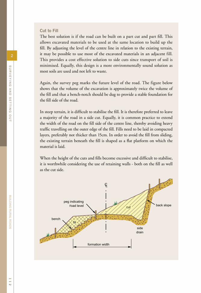
Cut to FillThe best solution is if the road can be built on a part cut and part fill. This allows excavated materials to be used at the same location to build up the fill. By adjusting the level of the centre line in relation to the existing terrain, it may be possible to use most of the excavated materials in an adjacent fill. This provides a cost effective solution to side cuts since transport of soil is minimised. Equally, this design is a more environmentally sound solution as most soils are used and not left to waste.
Again, the survey peg marks the future level of the road. The figure below shows that the volume of the excavation is approximately twice the volume of the fill and that a bench-notch should be dug to provide a stable foundation for the fill side of the road. In steep terrain, it is difficult to stabilise the fill. It is therefore preferred to leave a majority of the road in a side cut. Equally, it is common practice to extend the width of the road on the fill side of the centre line, thereby avoiding heavy traffic travelling on the outer edge of the fill. Fills need to be laid in compacted layers, preferably not thicker than 15cm. In order to avoid the fill from sliding, the existing terrain beneath the fill is shaped as a flat platform on which the material is laid.
When the height of the cuts and fills become excessive and difficult to stabilise, it is worthwhile considering the use of retaining walls - both on the fill as well as the cut side.
2
SU
RV
EY
ING
AN
D S
ET
TIN
G O
UT
BU
ILDIN
G R
UR
AL R
OA
DS
11
2

Embankments and FillsIn mountainous and hilly terrain, fills are essentially a result of providing a smooth vertical curvature across depressions in the terrain. Fills are normally required for the approaches to cross drainage structures such as bridges and culverts. Fills can also be used to lift the alignment above rocky or difficult soil conditions.
The most common use of fills is however, for the purpose of protecting the road and its pavement from any surface water during floods. By lifting the road pavement above prevalent flood levels, the pavement remains dry and its bearing capacity is maintained. If the road is submerged, it will obviously become impassable. If the flood waters are passing across the road, this will cause erosion of the pavement. Equally, a submerged pavement will be soaked in water and as a result have a compromised bearing capacity
Soils used for fills are normally similar to those found in the sub-grade of the road. With few exceptions a large variety of natural soils can be used for building road fills as long as they are placed in layers and compacted according to established quality standards.
Materials for building a fill need to be borrowed from nearby areas, preferably not too far away in order to limit the cost of transport. The ideal situation is of course if the soils can be supplied from a road section where a substantial cut is required. This is a common solution in hilly terrain where side cuts are commonplace.
In f lat f lood prone terrain, however, there will be a consistent demand for additional soils in order to lift the road onto an embankment. In such cases, the soils are obtained from borrow pits in close vicinity to the road. Side slopes on embankments and fills need careful attention. Slope gradients need to be carefully assessed based on the cohesive features of the soil. The slope gradients together with the embankment height will have a major impact on the total width of the road.
The survey pegs on both sides of the road show the height to be filled. The height is marked on the peg and measured from the top of the peg. In addition to setting out the road fill, there will also be a demand for setting out the necessary excavation work in the borrow pit.
2
SU
RV
EY
ING
AN
D S
ET
TIN
G O
UT
BU
ILDIN
G R
UR
AL R
OA
DS
11
3
