building a floor mounted joystick for flight simulator a floor mounted joystick for flight simulator...
TRANSCRIPT

Building a Floor mounted Joystick for Flight Simulator
An old Microsoft Sidewinder joystick was carefully dismantled and modified to make a “proper” floor mounted joystick. This is much more satisfying when flying those old stick and rudder aircraft such as the Chipmunk and Tiger Moth. The frame was made out of two shaped pieces of 1mm thick aluminium sheet which were originally my first attempt to build a rack for my Goflight units. It could be made out of aluminium angle just as well, but it needs to be strong. The diagonal brace was essential to provide lateral rigidity.

The finished structure ready for a first test flight. The side panels are 13” high, 2.5 “ wide at the top and 8” wide at the base. Only the 13” height measurement is critical. The distance apart of the two side frames is 6.75” so that the Sidewinder is a snug fit between them. The base is of a size to just fit in the desk kneehole with the rudder pedals butting up against the board, which puts them just in the right place. The feet of the pilot’s chair actually sit on the rear of the baseboard, holding it down with the pilot’s weight. The fulcrum of the long stick is 8” from the bottom, and connects directly to the 2.75” long shaft of the Sidewinder joystick. This gives 8” full deflection at the top of the new stick, which is just nice, with no need to move ones knees while turning. In fact in normal straight and level flight, stick movement is barely visible, you can just feel the pressure against the springs. The original springs in the Sidewinder are easily strong enough to centre the new stick positively.

The base of the Sidewinder was removed and screwed to a 5/8” chipboard baseboard (an old wardrobe shelf, actually) with 7 screws in a slightly smaller pitch circle than the original Sidewinder screws. 3/8” diameter holes were drilled in the Sidewinder fixing screw positions, so that the base of the Sidewinder could be again attached to its body through these holes with the original screws. This secured the Sidewinder firmly to the baseboard so that it should remain attached even during the most enthusiastic aerobatics!
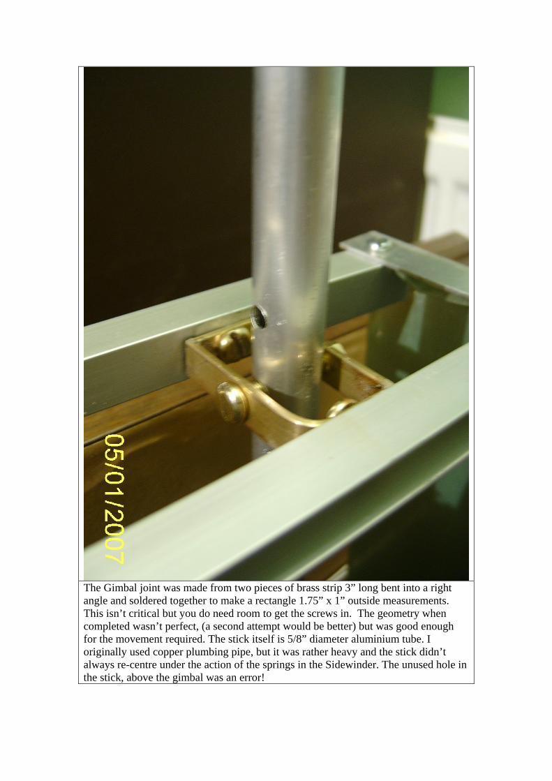
The Gimbal joint was made from two pieces of brass strip 3” long bent into a right angle and soldered together to make a rectangle 1.75” x 1” outside measurements. This isn’t critical but you do need room to get the screws in. The geometry when completed wasn’t perfect, (a second attempt would be better) but was good enough for the movement required. The stick itself is 5/8” diameter aluminium tube. I originally used copper plumbing pipe, but it was rather heavy and the stick didn’t always re-centre under the action of the springs in the Sidewinder. The unused hole in the stick, above the gimbal was an error!

The original 5-core cable was cut to leave just over 2 inches sticking out of the top of the Sidewinder stick when the handle was removed. I joined it to a length of 8 core twisted pair Ethernet cable, with the spare three wires trimmed back. The sleeves are short lengths of the insulation stripped from conventional 2.5mm twin and earth electrical cable and slid onto one side before soldering the wires.
The other end of the Ethernet cable I soldered directly to the small circuit board which fits in the handle, after removing the original short length of cable. I carefully wrote down the wire colours before removing them, and the corresponding colours of the Ethernet cabnle I had used at the other end. The holes in the top of the stick register with the original plastic dowels moulded in the handle to ensure it doesn’t twist on the shaft.
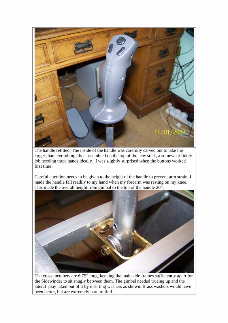
The handle refitted. The inside of the handle was carefully carved out to take the larger diameter tubing, then assembled on the top of the new stick, a somewhat fiddly job needing three hands ideally. I was slightly surprised when the buttons worked first time! Careful attention needs to be given to the height of the handle to prevent arm strain. I made the handle fall readily to my hand when my forearm was resting on my knee. This made the overall height from gimbal to the top of the handle 20”.
The cross members are 6.75” long, keeping the main side frames sufficiently apart for the Sidewinder to sit snugly between them. The gimbal needed trueing up and the lateral play taken out of it by inserting washers as shown. Brass washers would have been better, but are extremely hard to find.

The means of connecting the two sticks together was a bit of a headache for a while, as it needed to accommodate movement in 3 dimensions. The funnel idea worked perfectly first time. It is seen here in the central, neutral position, the two sticks almost touching. The funnel is a medium size one made of nylon, fairly rigid, and originally about 4” across the top, bought from a small ironmonger’s (what a rarity these days, and what a wonderful shop it is!) near my home. It was cut down to about 2.5” diameter, and the spout shortened and heated gently with a blowlamp and pushed onto the aluminium tube while hot. It didn’t need any other fixing.

Here it is seen with full left stick. Note the vertical gap between the two sticks which the funnel deals with perfectly. Note also that full left stick gives full right movement to the Sidewinder. But the Sidewinder is turned through 180o from its conventional position, so in fact it is passing a full left stick command to the aircraft.

After the first successful flight with the wiring completed. The whole will now be covered – probably in leathercloth with a gaiter around the gimbal. I shall probably use Velcro to fasten it, so that I can easily remove it for repairs and adjustments.