build your own inexpensive wind tunnel - … · build your own inexpensive wind tunnel continued...
TRANSCRIPT

I S S U E 2 5 2 J A N U A R Y 1 2 , 2 0 1 0
Apogee Components, Inc. — Your Source For Rocket Supplies That Will Take You To The “Peak-of-Flight”3355 Fillmore Ridge Heights
Colorado Springs, Colorado 80907-9024 USAwww.ApogeeRockets.com e-mail: [email protected]
Build Your OwnInexpensive Wind Tunnel
Feature Article:
Cover Photo: Apogee’s NEM-SAR rocket lifts off on a great fl ight. Get your’s today at:
www.ApogeeRockets.com/Nemsar.asp
Page 2 I S S U E 2 5 2 J A N U A R Y 1 0 , 2 0 1 0
You can subscribe to receive this e-zine FREE at the Apogee Components web site (www.ApogeeRockets.com), or by sending an e-mail to: [email protected] with “SUB-SCRIBE” as the subject line of the message.
About this Newsletter Newsletter Staff
Writer: Tim Van MilliganLayout / Cover Artist: Tim Van MilliganProofreader: Michelle Mason
By Tim Van Milligan
Continued on page 3
Build Your Own Inexpensive Wind Tunnel
This past December I was asked to present a work-shop on “rocket stability” for a group of 4H members here in Colorado Springs. This put me in a little bit of a quandary, because I was trying to think of a way to demonstrate the CP of a rocket. These young 4H club members were in the ages of about 8 to 13 years old, so I didn’t want to hit them with a lot of arm-waving and technical jargon that might go right over their heads.
I figured that a demonstration of balanced forces in a wind tunnel would be the best way to get the concept across to them about what is really the CP of a rocket.
ity.” To find this single point, we simply balance the rocket on our finger. When it lays level on our finger, we know that the force of gravity pulling down on the rocket on one side of our finger is equal to the force of gravity on the other side of the rocket.
Finding the place where the drag and lift forces are said to be concentrated (called the Center-of-Pres-sure) is harder to do. This is where a wind tunnel comes in.
What we can do with a wind tunnel is hold the rocket in the airflow (using a simple caliper device), and try to balance the rocket to where the nose doesn’t want to either point into the airflow, nor does it want to tilt away from the airflow direction.
That makes sense, right?
If it doesn’t make sense to you, imagine this scenario. You position the caliper near the nose cone, so that most of the rocket is behind the caliper, and you stick it into the airflow of the wind tunnel. As the air flows over the rocket, the forces behind the pivot point are greater than the ones in front of it, so the rocket will rotate to a position where the nose is pointed directly into the air flow.
Now move the pivot point so you’re holding the rocket by the end of the tail. Because most of the forces are now in front of the pivot point, the rocket will rotate so that the fins appear to be flying back-end-first into the airflow.
To find the point on the rocket where the forces in front of the pivot point equal the forces behind the pivot point, you need to slide the pivot to a position where the rocket doesn’t rotate at all. In other words, it sort of flys sideways
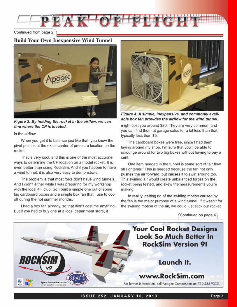
As a short review, when air flows over the rocket (or a rocket flies through the air), there are lift and drag forces that are created on various parts of the rocket. For exam-ple, as shown in Figure 2, there are lift and drag forces cre-ated on the nose, on the tube, and on the fins. The forces are all over the rocket, not just in one place.
Engineers like to simplify things, so we try to find a single (but equivalent) force, and the location where that force is said to act.
An example of this is the force of gravity. The gravity force acts on the various parts of the rocket, but to make things simple, we say that it is all concentrated at a single point on the rocket. That point we call the “center-of-grav-
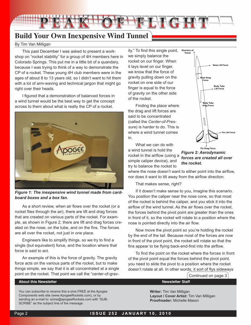
Figure 1: The inexpensive wind tunnel made from card-board boxes and a box fan.
Direction of Travel
Nose Lift Force
Nose Drag Force
Body Tube Lift Force
Body Tube Drag Force
Fin Lift Force
Fin Drag Force
Figure 2: Aerodynamic forces are created all over the rocket.
Page 3I S S U E 2 5 2 J A N U A R Y 1 0 , 2 0 1 0
Build Your Own Inexpensive Wind TunnelContinued from page 2
Continued on page 4
in the airflow.
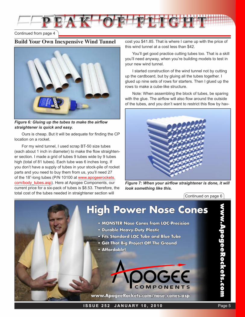
When you get it to balance just like that, you know the pivot point is at the exact center of pressure location on the rocket.
That is very cool, and this is one of the most accurate ways to determine the CP location on a model rocket. It is even better than using RockSim. And if you happen to have a wind tunnel, it is also very easy to demonstrate.
The problem is that most folks don’t have wind tunnels. And I didn’t either while I was preparing for my workshop with the local 4H club. So I built a simple one out of some big cardboard boxes and a simple box fan that I use to cool off during the hot summer months.
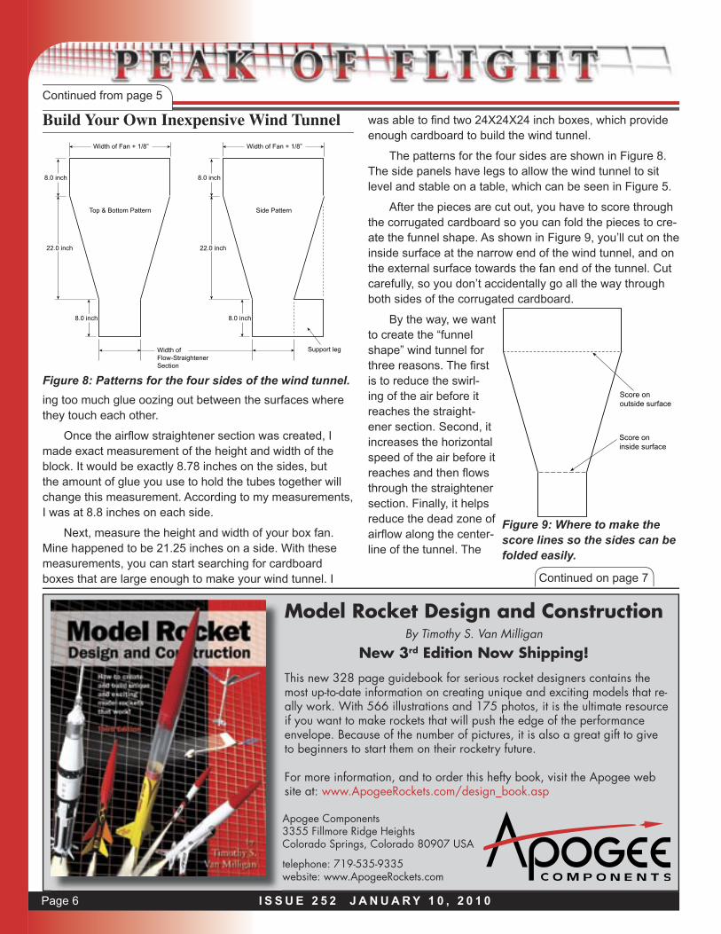
I had a box fan already, so that didn’t cost me anything. But if you had to buy one at a local department store, it
might cost you around $20. They are very common, and you can find them at garage sales for a lot less than that; typically less than $5.
The cardboard boxes were free, since I had them laying around my shop. I’m sure that you’ll be able to scrounge around for two big boxes without having to pay a cent.
One item needed in the tunnel is some sort of “air flow straightener.” This is needed because the fan not only pushes the air forward, but causes it to swirl around too. This swirling air would create unbalanced forces on the rocket being tested, and skew the measurements you’re making.
In reality, getting rid of the swirling motion caused by the fan is the major purpose of a wind tunnel. If it wasn’t for the swirling motion of the air, we could just stick our rocket
Space Foundation certified as an excellent teaching aid. For further information, call Apogee Components at: 719-535-9335.
www.RockSim.comv9
Your Cool Rocket Designs Look So Much Better In
RockSim Version 9!
Launch It.
Figure 3: By holding the rocket in the airflow, we can find where the CP is located.
Figure 4: A simple, inexpensive, and commonly avail-able box fan provides the airflow for the wind tunnel.

Page 4 I S S U E 2 5 2 J A N U A R Y 1 0 , 2 0 1 0
Build Your Own Inexpensive Wind TunnelContinued from page 3
in front of the fan to make the CP measurement. But the swirling motion is so bad for taking measurements that we have to do something to get rid of it.
The flow straightener section is one solution. Basically, what it does is to take the area of airflow in front of the fan, and break it up into smaller sections. A simple grid-like structure works great. We’ll force the air to flow through a section comprised of long tubes. As the air comes out of the fan and hits the front of the tubes, it has to stop swirling in a giant circle, and change direction into a linear one to get through the tubes. As it exits out of the tubes, it should be mostly “laminar” (which means it is flowing in a nice smooth and straight line).
The smaller the tubes in the grid, the straighter the air will be coming out of the tubes, where it will be flowing over the rocket. Some of the best wind tunnels used by real engineers use tubes the size of 1/8-inch diameter launch lugs. The disadvantage of these small-diameter tubes is that it takes a lot of tubes, which makes it more expensive to construct a wind tunnel.
The other disadvantage is that the edges of the small tubes block off a lot of surface area and it will slow down the airflow coming out of the tubes. So if you want more airflow, you’ll need a more powerful fan to ram the air
through the small tubes. Unfortunately, a more powerful fan will create a lot more swirling action in the air that you need to straighten out. It is a crazy balancing act, but one of the challenges that makes engineering so much fun. That is why a good wind tunnel with high air speed and very smooth airflow is very expensive.
Continued on page 5
ww
w.A
pogeeRock
ets.co
m
www.ApogeeRockets.com/All_rocket_kits.asp
Looking For A Fun Rocket Kit?Roam In Our Forest of Over 170 Different Types
• Unique and exotic kits from over 20 different manufacturers
• Skill Levels range from “easy” to “fiendish”
• Sizes from 1/4A motor to level-2-high-power
• We build & fly them to find out what they’re like, saving you grief
• More new ones arriv-ing all the time
• Educational bulk packs available too
Figure 5: The lattice structure of tubes is to make sure the air flows out nice and straight.
Page 5I S S U E 2 5 2 J A N U A R Y 1 0 , 2 0 1 0
Build Your Own Inexpensive Wind TunnelContinued from page 4
Ours is cheap. But it will be adequate for finding the CP location on a rocket.
For my wind tunnel, I used scrap BT-50 size tubes (each about 1 inch in diameter) to make the flow straighten-er section. I made a grid of tubes 9 tubes wide by 9 tubes high (total of 81 tubes). Each tube was 6 inches long. If you don’t have a supply of tubes in your stock-pile of rocket parts and you need to buy them from us, you’ll need 27 of the 18”-long tubes (P/N 10100 at www.apogeerockets.com/body_tubes.asp). Here at Apogee Components, our current price for a six-pack of tubes is $8.53. Therefore, the total cost of the tubes needed in straightener section will
cost you $41.85. That is where I came up with the price of this wind tunnel at a cost less than $42.
You’ll get good practice cutting tubes too. That is a skill you’ll need anyway, when you’re building models to test in your new wind tunnel.
I started construction of the wind tunnel not by cutting up the cardboard, but by gluing all the tubes together. I glued up nine sets of rows for starters. Then I glued up the rows to make a cube-like structure.
Note: When assembling the block of tubes, be sparing with the glue. The airflow will also flow around the outside of the tubes, and you don’t want to restrict this flow by hav-
High Power Nose Cones
ww
w.A
pogeeRock
ets.co
m
• MONSTER Nose Cones from LOC-Precision• Durable Heavy-Duty Plastic• Fits Standard LOC Tube and Blue Tube• Get That Big Project Off The Ground• Affordable!
www.ApogeeRockets.com/nose_cones.asp
Figure 6: Gluing up the tubes to make the airflow straightener is quick and easy.
Continued on page 6
Figure 7: When your airflow straightener is done, it will look something like this.
Page 6 I S S U E 2 5 2 J A N U A R Y 1 0 , 2 0 1 0
Continued on page 7
Model Rocket Design and ConstructionBy Timothy S. Van Milligan
New 3rd Edition Now Shipping!
Apogee Components3355 Fillmore Ridge HeightsColorado Springs, Colorado 80907 USA
telephone: 719-535-9335website: www.ApogeeRockets.com
This new 328 page guidebook for serious rocket designers contains the most up-to-date information on creating unique and exciting models that re-ally work. With 566 illustrations and 175 photos, it is the ultimate resource if you want to make rockets that will push the edge of the performance envelope. Because of the number of pictures, it is also a great gift to give to beginners to start them on their rocketry future.
For more information, and to order this hefty book, visit the Apogee web site at: www.ApogeeRockets.com/design_book.asp
Build Your Own Inexpensive Wind TunnelContinued from page 5
Width of Flow-StraightenerSection
8.0 inch
Width of Fan + 1/8”
8.0 inch
22.0 inch
8.0 inch
Width of Fan + 1/8”
8.0 inch
22.0 inch
Top & Bottom Pattern Side Pattern
Support leg
ing too much glue oozing out between the surfaces where they touch each other.
Once the airfl ow straightener section was created, I made exact measurement of the height and width of the block. It would be exactly 8.78 inches on the sides, but the amount of glue you use to hold the tubes together will change this measurement. According to my measurements, I was at 8.8 inches on each side.
Next, measure the height and width of your box fan. Mine happened to be 21.25 inches on a side. With these measurements, you can start searching for cardboard boxes that are large enough to make your wind tunnel. I
Figure 8: Patterns for the four sides of the wind tunnel.
was able to fi nd two 24X24X24 inch boxes, which provide enough cardboard to build the wind tunnel.
The patterns for the four sides are shown in Figure 8. The side panels have legs to allow the wind tunnel to sit level and stable on a table, which can be seen in Figure 5.
After the pieces are cut out, you have to score through the corrugated cardboard so you can fold the pieces to cre-ate the funnel shape. As shown in Figure 9, you’ll cut on the inside surface at the narrow end of the wind tunnel, and on the external surface towards the fan end of the tunnel. Cut carefully, so you don’t accidentally go all the way through both sides of the corrugated cardboard.
By the way, we want to create the “funnel shape” wind tunnel for three reasons. The fi rst is to reduce the swirl-ing of the air before it reaches the straight-ener section. Second, it increases the horizontal speed of the air before it reaches and then fl ows through the straightener section. Finally, it helps reduce the dead zone of airfl ow along the center-line of the tunnel. The
Score onoutside surface
Score oninside surface
Figure 9: Where to make the score lines so the sides can be folded easily.
Page 7I S S U E 2 5 2 J A N U A R Y 1 0 , 2 0 1 0
Continued on page 8
Want A Scale Model?
ww
w.A
pogeeRock
ets.co
m
• It’s Your Passion On Desktop Display• Choose From 45 Different Rockets• Peanut Scale To Giant Scale• Easy to Very Challenging• Affordable!
www.ApogeeRockets.com/Scale_Rocket_Kits.asp
Build Your Own Inexpensive Wind TunnelContinued from page 6
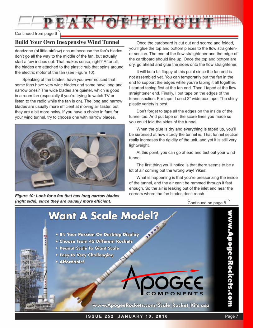
deadzone (of little airflow) occurs because the fan’s blades don’t go all the way to the middle of the fan, but actually start a few inches out. That makes sense, right? After all, the blades are attached to the plastic hub that spins around the electric motor of the fan (see Figure 10).
Speaking of fan blades, have you ever noticed that some fans have very wide blades and some have long and narrow ones? The wide blades are quieter, which is good in a room fan (especially if you’re trying to watch TV or listen to the radio while the fan is on). The long and narrow blades are usually more efficient at moving air faster, but they are a bit more noisy. If you have a choice in fans for your wind tunnel, try to choose one with narrow blades.
Figure 10: Look for a fan that has long narrow blades (right side), since they are usually more efficient.
Once the cardboard is cut out and scored and folded, you’ll glue the top and bottom pieces to the flow straighten-er section. The end of the flow straightener and the edge of the cardboard should line up. Once the top and bottom are dry, go ahead and glue the sides onto the flow straightener.
It will be a bit floppy at this point since the fan end is not assembled yet. You can temporarily put the fan in the end to support the edges while you’re taping it all together. I started taping first at the fan end. Then I taped at the flow straightener end. Finally, I put tape on the edges of the funnel section. For tape, I used 2” wide box tape. The shiny plastic variety is best.
Don’t forget to tape all the edges on the inside of the tunnel too. And put tape on the score lines you made so you could fold the sides of the tunnel.
When the glue is dry and everything is taped up, you’ll be surprised at how sturdy the tunnel is. That funnel section really increases the rigidity of the unit, and yet it is still very lightweight.
At this point, you can go ahead and test out your wind tunnel.
The first thing you’ll notice is that there seems to be a lot of air coming out the wrong way! Yikes!
What is happening is that you’re pressurizing the inside of the tunnel, and the air can’t be rammed through it fast enough. So the air is leaking out of the inlet end near the corners where the fan blades don’t reach.
Page 8 I S S U E 2 5 2 J A N U A R Y 1 0 , 2 0 1 0
Continued on page 9
High Power Tubes & Couplers ww
w.A
pogeeRock
ets.co
m
• Won’t Shatter Like Brittle Phenolic Tubes!• Super Smooth Surface With Tight Spirals• Standard LOC Diameters Up To 6 inches
• Cut and Slot With Standard Tools• No Fiberglass Wrap Needed
• Sands and Paints Easily• Cheaper than Fiber-
glass
www.ApogeeRockets.com/blue_tubes.asp
Blue Tube FromAlways ReadyRocketry
Build Your Own Inexpensive Wind TunnelContinued from page 7
How To Increase The Flow Of Air Through The Wind Tunnel
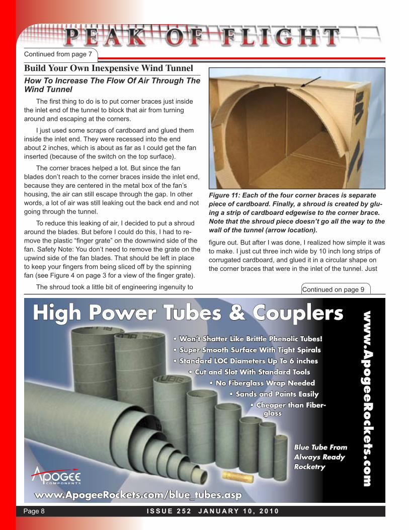
The first thing to do is to put corner braces just inside the inlet end of the tunnel to block that air from turning around and escaping at the corners.
I just used some scraps of cardboard and glued them inside the inlet end. They were recessed into the end about 2 inches, which is about as far as I could get the fan inserted (because of the switch on the top surface).
The corner braces helped a lot. But since the fan blades don’t reach to the corner braces inside the inlet end, because they are centered in the metal box of the fan’s housing, the air can still escape through the gap. In other words, a lot of air was still leaking out the back end and not going through the tunnel.
To reduce this leaking of air, I decided to put a shroud around the blades. But before I could do this, I had to re-move the plastic “finger grate” on the downwind side of the fan. Safety Note: You don’t need to remove the grate on the upwind side of the fan blades. That should be left in place to keep your fingers from being sliced off by the spinning fan (see Figure 4 on page 3 for a view of the finger grate).
The shroud took a little bit of engineering ingenuity to
Figure 11: Each of the four corner braces is separate piece of cardboard. Finally, a shroud is created by glu-ing a strip of cardboard edgewise to the corner brace. Note that the shroud piece doesn’t go all the way to the wall of the tunnel (arrow location).
figure out. But after I was done, I realized how simple it was to make. I just cut three inch wide by 10 inch long strips of corrugated cardboard, and glued it in a circular shape on the corner braces that were in the inlet of the tunnel. Just
Page 9I S S U E 2 5 2 J A N U A R Y 1 0 , 2 0 1 0
Continued on page 10
Build Your Own Inexpensive Wind TunnelContinued from page 8
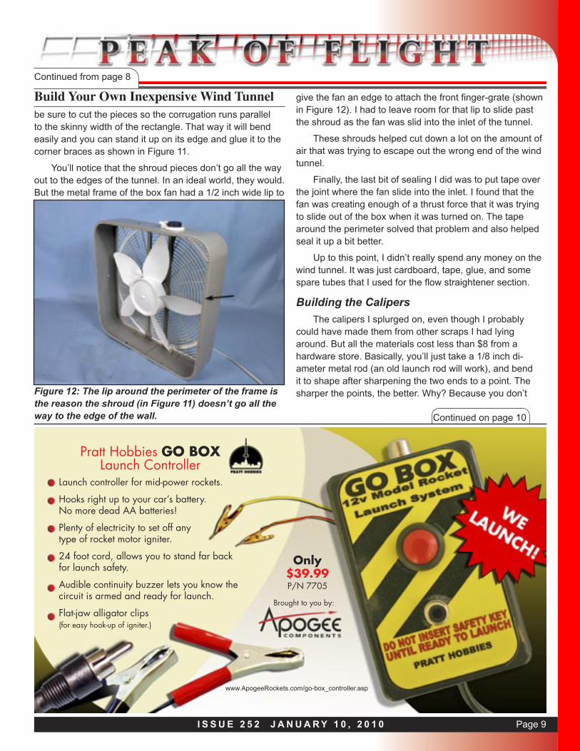
be sure to cut the pieces so the corrugation runs parallel to the skinny width of the rectangle. That way it will bend easily and you can stand it up on its edge and glue it to the corner braces as shown in Figure 11.
You’ll notice that the shroud pieces don’t go all the way out to the edges of the tunnel. In an ideal world, they would. But the metal frame of the box fan had a 1/2 inch wide lip to
Figure 12: The lip around the perimeter of the frame is the reason the shroud (in Figure 11) doesn’t go all the way to the edge of the wall.
give the fan an edge to attach the front finger-grate (shown in Figure 12). I had to leave room for that lip to slide past the shroud as the fan was slid into the inlet of the tunnel.
These shrouds helped cut down a lot on the amount of air that was trying to escape out the wrong end of the wind tunnel.
Finally, the last bit of sealing I did was to put tape over the joint where the fan slide into the inlet. I found that the fan was creating enough of a thrust force that it was trying to slide out of the box when it was turned on. The tape around the perimeter solved that problem and also helped seal it up a bit better.
Up to this point, I didn’t really spend any money on the wind tunnel. It was just cardboard, tape, glue, and some spare tubes that I used for the flow straightener section.
Building the Calipers
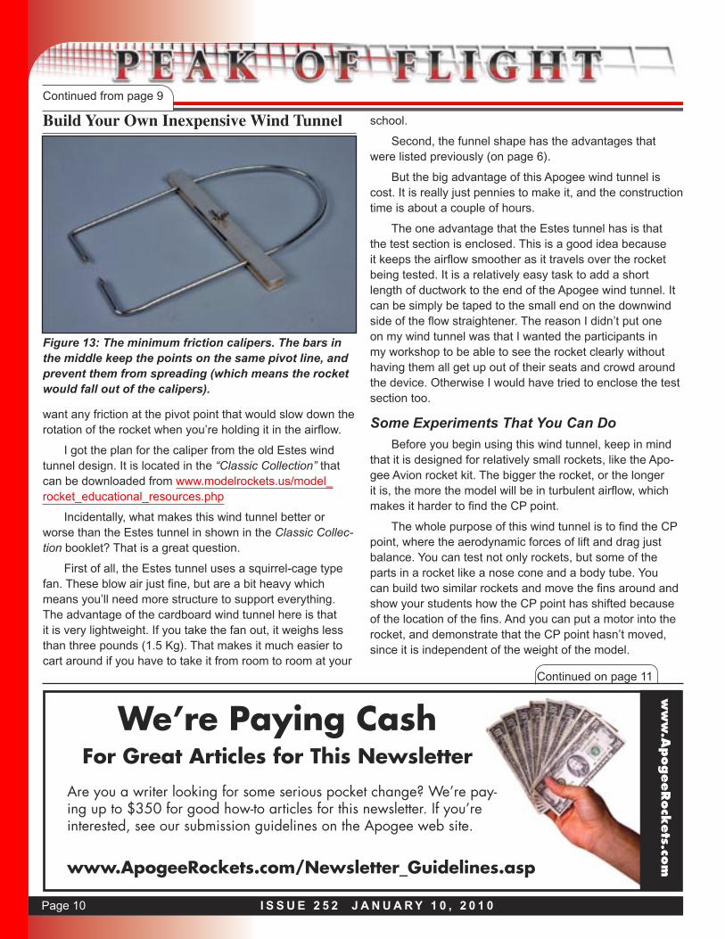
The calipers I splurged on, even though I probably could have made them from other scraps I had lying around. But all the materials cost less than $8 from a hardware store. Basically, you’ll just take a 1/8 inch di-ameter metal rod (an old launch rod will work), and bend it to shape after sharpening the two ends to a point. The sharper the points, the better. Why? Because you don’t
Launch controller for mid-power rockets.
Hooks right up to your car’s battery.No more dead AA batteries!
Plenty of electricity to set off any type of rocket motor igniter.
24 foot cord, allows you to stand far backfor launch safety.
Audible continuity buzzer lets you know the circuit is armed and ready for launch.
Flat-jaw alligator clips(for easy hook-up of igniter.)
Pratt Hobbies GO BOX Launch Controller
Brought to you by:
Only $39.99P/N 7705
www.ApogeeRockets.com/go-box_controller.asp
Page 10 I S S U E 2 5 2 J A N U A R Y 1 0 , 2 0 1 0
Build Your Own Inexpensive Wind TunnelContinued from page 9
want any friction at the pivot point that would slow down the rotation of the rocket when you’re holding it in the airflow.
I got the plan for the caliper from the old Estes wind tunnel design. It is located in the “Classic Collection” that can be downloaded from www.modelrockets.us/model_rocket_educational_resources.php
Incidentally, what makes this wind tunnel better or worse than the Estes tunnel in shown in the Classic Collec-tion booklet? That is a great question.
First of all, the Estes tunnel uses a squirrel-cage type fan. These blow air just fine, but are a bit heavy which means you’ll need more structure to support everything. The advantage of the cardboard wind tunnel here is that it is very lightweight. If you take the fan out, it weighs less than three pounds (1.5 Kg). That makes it much easier to cart around if you have to take it from room to room at your
school.
Second, the funnel shape has the advantages that were listed previously (on page 6).
But the big advantage of this Apogee wind tunnel is cost. It is really just pennies to make it, and the construction time is about a couple of hours.
The one advantage that the Estes tunnel has is that the test section is enclosed. This is a good idea because it keeps the airflow smoother as it travels over the rocket being tested. It is a relatively easy task to add a short length of ductwork to the end of the Apogee wind tunnel. It can be simply be taped to the small end on the downwind side of the flow straightener. The reason I didn’t put one on my wind tunnel was that I wanted the participants in my workshop to be able to see the rocket clearly without having them all get up out of their seats and crowd around the device. Otherwise I would have tried to enclose the test section too.
Some Experiments That You Can Do
Before you begin using this wind tunnel, keep in mind that it is designed for relatively small rockets, like the Apo-gee Avion rocket kit. The bigger the rocket, or the longer it is, the more the model will be in turbulent airflow, which makes it harder to find the CP point.
The whole purpose of this wind tunnel is to find the CP point, where the aerodynamic forces of lift and drag just balance. You can test not only rockets, but some of the parts in a rocket like a nose cone and a body tube. You can build two similar rockets and move the fins around and show your students how the CP point has shifted because of the location of the fins. And you can put a motor into the rocket, and demonstrate that the CP point hasn’t moved, since it is independent of the weight of the model.
Continued on page 11
Figure 13: The minimum friction calipers. The bars in the middle keep the points on the same pivot line, and prevent them from spreading (which means the rocket would fall out of the calipers).
ww
w.A
pogeeRock
ets.co
m
We’re Paying CashFor Great Articles for This Newsletter
Are you a writer looking for some serious pocket change? We’re pay-ing up to $350 for good how-to articles for this newsletter. If you’re interested, see our submission guidelines on the Apogee web site.
www.ApogeeRockets.com/Newsletter_Guidelines.asp
Page 11I S S U E 2 5 2 J A N U A R Y 1 0 , 2 0 1 0
Build Your Own Inexpensive Wind TunnelContinued from page 10
Unfortunately, without a balance, measuring the actual forces on the rocket is not possible. You’ll only be able to find the CP location. But it should be fairly accurate for that task (and it is something that a swing test can’t do)
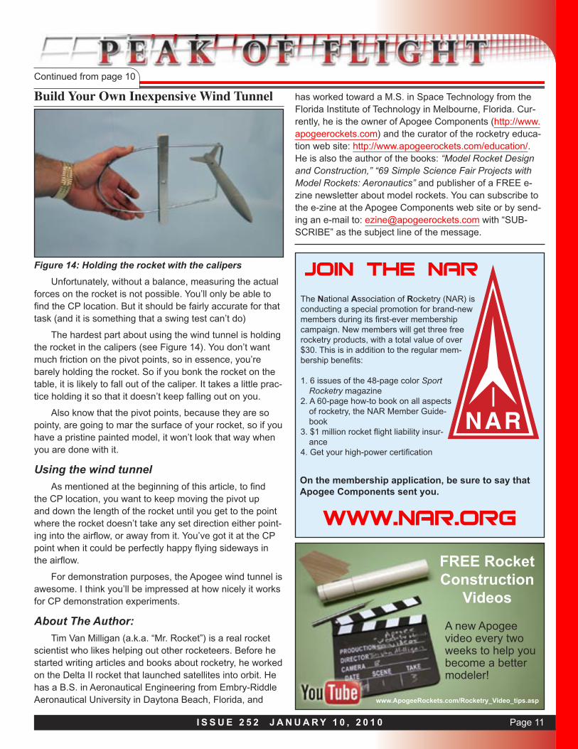
The hardest part about using the wind tunnel is holding the rocket in the calipers (see Figure 14). You don’t want much friction on the pivot points, so in essence, you’re barely holding the rocket. So if you bonk the rocket on the table, it is likely to fall out of the caliper. It takes a little prac-tice holding it so that it doesn’t keep falling out on you.
Also know that the pivot points, because they are so pointy, are going to mar the surface of your rocket, so if you have a pristine painted model, it won’t look that way when you are done with it.
Using the wind tunnel
As mentioned at the beginning of this article, to find the CP location, you want to keep moving the pivot up and down the length of the rocket until you get to the point where the rocket doesn’t take any set direction either point-ing into the airflow, or away from it. You’ve got it at the CP point when it could be perfectly happy flying sideways in the airflow.
For demonstration purposes, the Apogee wind tunnel is awesome. I think you’ll be impressed at how nicely it works for CP demonstration experiments.
About The Author:
Tim Van Milligan (a.k.a. “Mr. Rocket”) is a real rocket scientist who likes helping out other rocketeers. Before he started writing articles and books about rocketry, he worked on the Delta II rocket that launched satellites into orbit. He has a B.S. in Aeronautical Engineering from Embry-Riddle Aeronautical University in Daytona Beach, Florida, and
has worked toward a M.S. in Space Technology from the Florida Institute of Technology in Melbourne, Florida. Cur-rently, he is the owner of Apogee Components (http://www.apogeerockets.com) and the curator of the rocketry educa-tion web site: http://www.apogeerockets.com/education/. He is also the author of the books: “Model Rocket Design and Construction,” “69 Simple Science Fair Projects with Model Rockets: Aeronautics” and publisher of a FREE e-zine newsletter about model rockets. You can subscribe to the e-zine at the Apogee Components web site or by send-ing an e-mail to: [email protected] with “SUB-SCRIBE” as the subject line of the message.
Figure 14: Holding the rocket with the calipers
FREE RocketConstruction
Videos
A new Apogee video every two weeks to help you become a better modeler!
www.ApogeeRockets.com/Rocketry_Video_tips.asp
Join The NAR
The National Association of Rocketry (NAR) is conducting a special promotion for brand-new members during its first-ever membership campaign. New members will get three free rocketry products, with a total value of over $30. This is in addition to the regular mem-bership benefits:
1. 6 issues of the 48-page color Sport Rocketry magazine
2. A 60-page how-to book on all aspects of rocketry, the NAR Member Guide-book
3. $1 million rocket flight liability insur-ance
4. Get your high-power certification
On the membership application, be sure to say that Apogee Components sent you.
www.NAR.org