build your own clone classic brit 45 kit instructionsbyocelectronics.com/brit45instructions.pdf ·...
TRANSCRIPT

1
Build Your Own Clone Classic Brit 45
Kit Instructions (Revision 1.0)
WARNING!!! HIGH VOLTAGE!!!! Tube amplifiers contain high voltage that can cause injury and even death. Please use extreme caution and common sense when building this kit. Do not attempt to do anything to your amp while it is plugged in other than take voltage readings as necessary or actually playing an instrument through it as it was intended. Don't just turn the power off!!! Always unplug the power cord from the socket before working on your amp!!! The mains supply can still electrocute you AND the power filter capacitors can still retain a charge powerful enough to kill you. Always unplug the power cord from the socket before working on your amp.
2
DISCLAIMER Build at your own risk!!! BYOC, Inc. is not liable or responsible for any damages, injuries, or deaths that may incur from or while building this kit. It is your own responsibility to follow proper safety precautions. Never attempt to build, modify, repair, or perform any sort of maintenance on your amplifier while the power cord is plugged into an AC power source. This kit contains only the amplifier chassis. It is intended to be housed in a non-conductive, electrically insulated cabinet or enclosure. This kit does not come with any such cabinet or enclosure and is not intended to be used without one. It is your responsibility to house this amplifier kit in a proper cabinet or enclosure before attempting to use it. Warranty: BYOC, Inc. guarantees that your kit will be complete and that all parts and components will arrive as described, functioning and free of defect. Soldering, clipping, cutting, stripping, or using any of the components in anyway voids this guarantee. BYOC, Inc. guarantees that the instructions for your kit will be free of any majors errors that would cause you to permanently damage any components in your kit, but does not guarantee that the instructions will be free of typos or minor errors. BYOC, Inc. does not warranty the completed kit as a whole functioning unit, nor do we warranty any of the individual parts once they have been used. If you have a component that is used, but feel it was defective prior to you using it, we reserve the right to determine whether or not the component was faulty upon arrival. Please direct all warranty issues to: [email protected] This would include any missing parts issues. Return: BYOC, Inc. accepts returns and exchanges on all products for any reason, as long as they are unused. We do not accept partial kit returns. Returns and exchanges are for the full purchase price less the cost of shipping and/or any promotional pricing. Return shipping is the customer’s responsibility. This responsibility not only includes the cost of shipping, but accountability of deliver as well. Please contact [email protected] to receive a return authorization before mailing. Tech Support: BYOC, Inc. makes no promises or guarantees that you will successfully complete your kit in a satisfactory manor. Nor does BYOC,

3
Inc. promise or guarantee that you will receive any technical support. Purchasing a product from BYOC, Inc. does not entitle you to any amount of technical support. BYOC, Inc. does not promise or guarantee that any technical support you may receive will be able to resolve any or all issues you may be experiencing. That being said, we will do our best to help you as much as we can. Our philosophy at BYOC is that we will help you only as much as you are willing to help yourself. We have a wonderful and friendly DIY discussion forum with an entire section devoted to the technical support and modifications of BYOC kits. www.byocelectronics.com/board When posting a tech support thread on the BYOC forum, please post it in the correct lounge, and please title your thread appropriately. If everyone titles their threads “HELP!”, it makes it impossible for the people who are helping you to keep track of your progress. A very brief description of your specific problem will do. It will also make it easier to see if someone else is having or has had the same problem as you. The question you are about to ask may already be answered. Here is a list of things that you should include in the body of your tech support thread: 1. A detailed explanation of what the problem is. (Not just, “It doesn’t work, help”) 2. Photo that clearly shows your circuit board. 3. Photo that clearly shows the tube-side of inside of the chassis. 4. Photo that clearly shows the inside of the front of the chassis. 5. Photo that clearly shows your wiring going from the circuit board to the pots and any other switches (only if your kit has non-PC mounted pots and switches). 6. Does the indicator light come on? Also, please only post photos that are in focus. You're only wasting both parties' time if you post out of focus, low-resolution photos from your cell phone. Credits: Written by: N.W. Kenning & K. Vonderhulls Artwork & Photography by: N.W. Kenning & K. Vonderhulls Quality Control by: R. Matthews Revision Notes: None All material in this document is copyrighted 2015 by BYOC, Inc.

4
CLASSIC BRIT 45 KIT INSTRUCTION INDEX
Parts Checklist…………………………………………………page 5 - 8 Chassis Assembly………….………...…………………….…...page 9 - 20 Wiring (Power Section)…………….………………………….page 21 - 53 Populating the Circuit Board……………..…………………..page 54 - 68 Wiring (Tube Side)…………………………………………….page 69 - 77 Wiring (Potentiometer Side)………..…………………………page 78 – 90 Wiring Layouts/Diagrams……………………………………..page 91 - 92 Turning Your Amp on for the First Time……………………page 93 – 95 Biasing…………………………………………………….…….page 96 Operating Overview……………………………………….…...page 97 -98 Diagrams and Schematic………………………………….…...page 99 - 102

5
Parts Checklist for Classic Brit 45 Kit
Resistors: 1/2watt (4th color band will either be silver or gold): 1 – 470 ohm (Yellow/Purple/Brown) 2 – 820 ohm (Gray/Red/Brown) 1 – 10K (Brown/Black/Orange) 1 – 15K (Brown/Green/Orange) 1 – 27K (Red/Purple/Orange) 2 – 56K (Green/Blue/Orange) 4 – 68K (Blue/Gray/Orange) 1 – 82K (Gray/Red/Orange) 5 – 100K (Brown/Black/Yellow) 1 – 180K (Brown/Gray/Yellow) 2 – 220K (Red/Red/Yellow) 2 – 270K (Red/Purple/Yellow) 4 – 1M (Brown/Black/Green) 1watt: 2 – 1 Ohm (Brown/Black.Black.Silver/Brown) 1 – 10K (Brown/Black/Black/Red/Brown 2watt: 2 – 470Ohm (Yellow/Purple/Black/Black/Brown) 1 – 8.2K (Gray/Red/Black/Brown/Brown) 3watt: 1 – 1K (Brown/Black/Black/Brown/Brown or just say “1k” on them)

6
Diode: 1 – 1n4007 Capacitors: 1 – 47pF (Red with ‘47’ on the body) 1 – 100pF (Red with ‘100’ on the body) 1 – 250pF (Red with ‘250’ on the body) 1 – 500pF (Red with ‘500’ on the body) 4 – 0.1uF axial leaded polyester film 5 – 0.022uF axial leaded polyester film 2 – 10uF/150V Electrolytic 1 – 16uF/450V Electrolytic 1 – 220uF/25V (or 50V) Electrolytic 1 – 16+16 Electrolytic (Really big with three terminals) 1 – 32+32 Electrolytic (Really big with three terminals) Potentiometers: 3 – A1M (Bass, Loudness 1, and Loudness 2) 1 – B5K (Presence) 1 – B25K (Middle) 1 – B250K (Treble) Hardware: 1 - Chassis 1 - Circuit board 3 - Circuit board hex standoffs 1 – Rotary Switch 2 – ON/OFF SPST Toggle switch 3 - 8 pin tube sockets 3 – Octal Tube Retainer Clips

7
3 - 9 pin tube socket w/shield 6 – ¼” Shorting Mono Jacks 1 - Indicator Lamp 1 - 6' 3-conductor power cord 1 - Power cord socket 2 – black screws for power cord socket 1 - Panel mounted fuse holder 1 - Flat-Mount Fuse Holder 1 - Mains Fuse (3A Slow-Blow for 120V, 2A Slow-Blow for 220V or 240V) 1 - HT Fuse (500mA) 3 - Rubber Grommets 25 – M3 screws 12 – M3 nuts 6 - #4 lock washer 4 - Wire nuts 6 – M4 screws 6 – M4 nuts 6 – M4 flat washers 6 - #8 internal lock washers (for the M4 screws/nuts) 4 - #10 nut 4 - #10 flat washer 2 - #10 internal lock washer 2 – lock washer w/solder terminal Wire: 3’ – Green 20AWG 4' - White 20AWG 3' - Black 20AWG 4' - Yellow 20AWG 4' - Brown 20AWG 2' - Red 20AWG

8
3.5' - Bare Bus Save the wire you clip from the transformers as well. This will provide you with more than enough wire to complete your kit. Tubes: 3 – ECC83 2 – KT66 1 – GZ34 Transformers: 1 – Power Transformer (Classic Tone 40-18033) 1 – Output Transformer (Classic Tone 40-18039) 1 – Choke (Classic Tone 40-18058)

9
Chassis Assembly
Step 1: Add grommets

10
Step 2: Mount the transformers. Orient the power transformer so that the side with the green wires is towards the “tube side” of the chassis. Orient the output transformer so that the side with the orange/blue/yellow/green wires is towards the “tube side” of the
chassis. Orient the choke so that the side with the wires is over the grommet hole. The power transformer will already have mounting screws attached. Use #10 nuts and flat washers for the power transformer. Use the two #10 lock washers for the screws closer to the outside of the chassis. Use the two lockwashers with solder terminals on the screws closer to the inside of the chassis. Use the M4
11
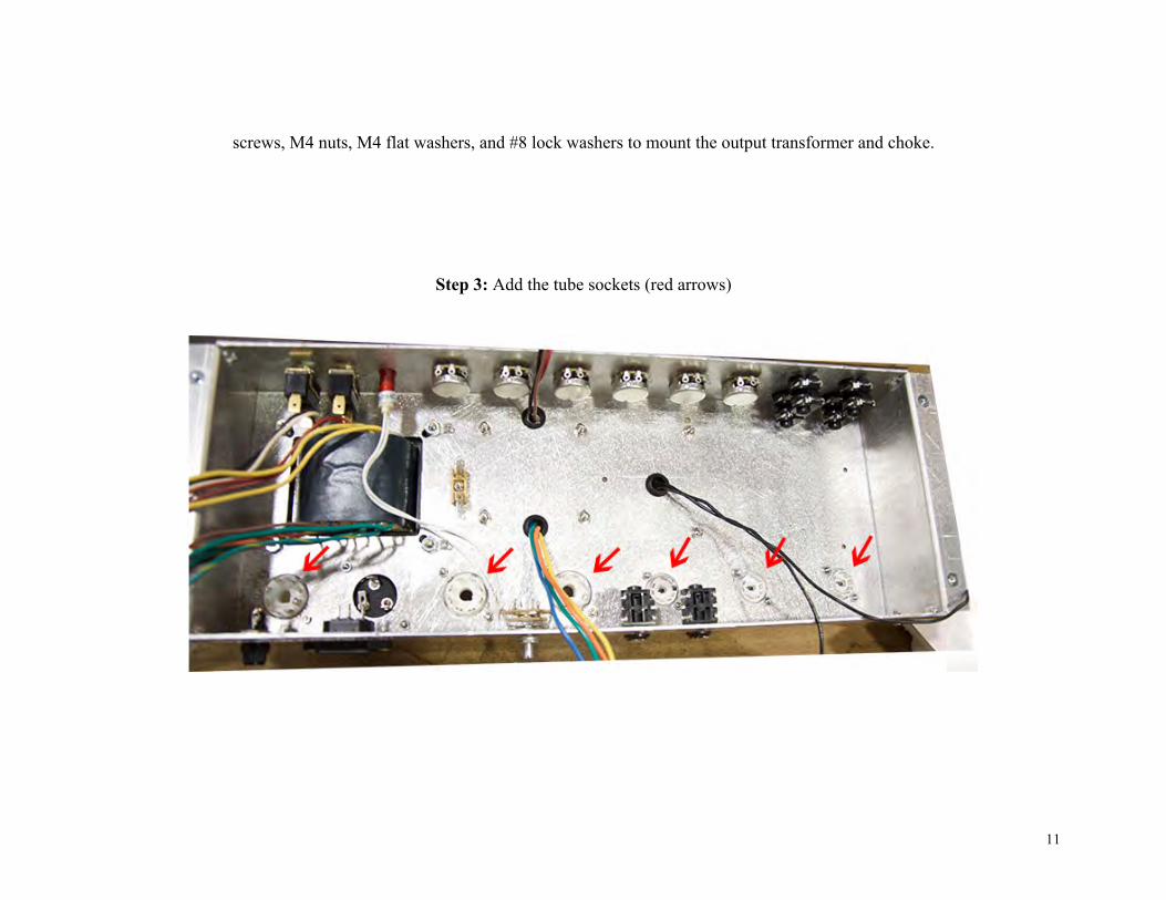
screws, M4 nuts, M4 flat washers, and #8 lock washers to mount the output transformer and choke.
Step 3: Add the tube sockets (red arrows)
12
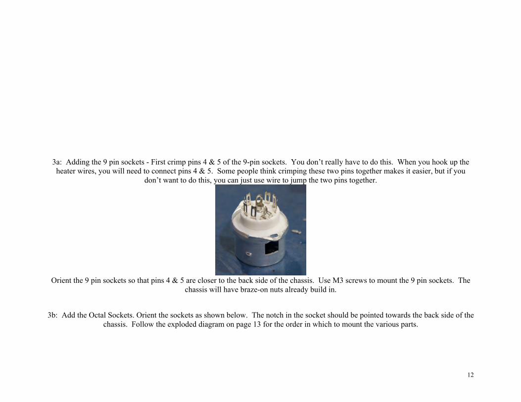
3a: Adding the 9 pin sockets - First crimp pins 4 & 5 of the 9-pin sockets. You don’t really have to do this. When you hook up the heater wires, you will need to connect pins 4 & 5. Some people think crimping these two pins together makes it easier, but if you
don’t want to do this, you can just use wire to jump the two pins together.
Orient the 9 pin sockets so that pins 4 & 5 are closer to the back side of the chassis. Use M3 screws to mount the 9 pin sockets. The
chassis will have braze-on nuts already build in.
3b: Add the Octal Sockets. Orient the sockets as shown below. The notch in the socket should be pointed towards the back side of the
chassis. Follow the exploded diagram on page 13 for the order in which to mount the various parts.
13
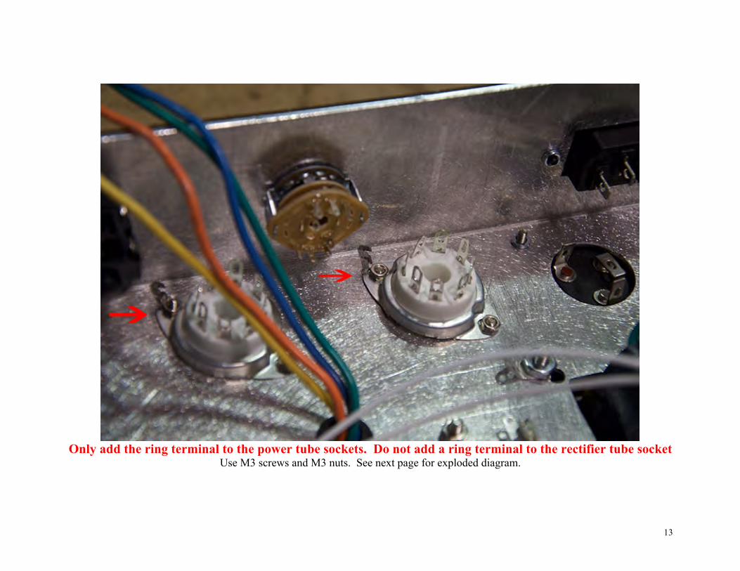
Only add the ring terminal to the power tube sockets. Do not add a ring terminal to the rectifier tube socket
Use M3 screws and M3 nuts. See next page for exploded diagram.

14

15
Step 4: Mount the 16uF x 16uF capacitor to the outside of the chassis. Use the mounting ring to mount to chassis. Use M3 screws to mount to chassis. Use M3 screw and nut to tighten clamp. Make sure the red terminal is not touching the chassis. If it is, resituate the capacitor in its mounting ring so that it is not touching. You will not need the yellow terminal. You can bend it out of the way if you
want.

16
Step 5: Add flat mount fuse holder. Use 1 x M3 screw and 1 x M3 nut.

17
Step 6: Add the rear plexi panel and rear panel mounted parts !!!!The plexi panels are EXTREMELY DELICATE!!!!
6a: Mount the AC Power Cord Receptacle. Use black flat head screws for power cord receptacle.
18
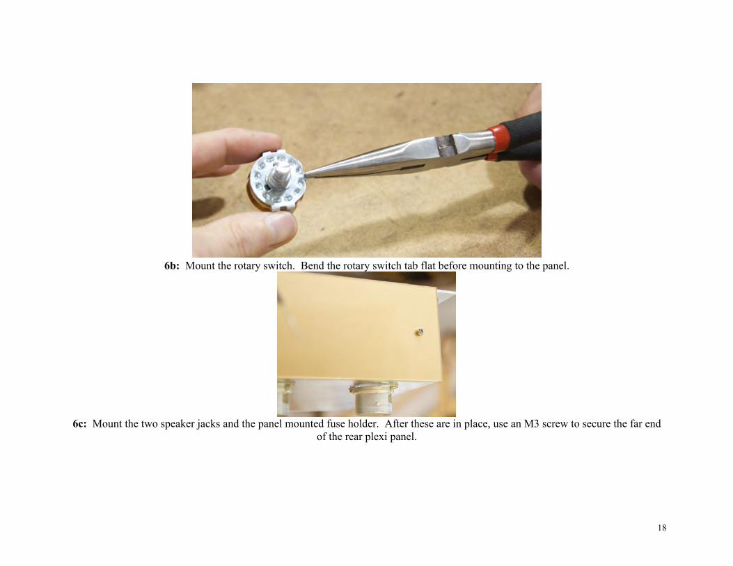
6b: Mount the rotary switch. Bend the rotary switch tab flat before mounting to the panel.
6c: Mount the two speaker jacks and the panel mounted fuse holder. After these are in place, use an M3 screw to secure the far end
of the rear plexi panel.

19
Step 7: Add the front plexi panel and panel mounted parts
7a: Add the Switches and lamp. Orient the toggle switches so that the “ON” arrow is pointing in the same direction as the “ON” label on the plexi panel. The lamp is not mounted with any nuts or bolts. You simply push it through its hole and it will lock in place. The
lamp may be loose fitting. You can use a thick glue (i.e., a glue that is not runny) to hold it in place better once you have finished building your amp.

20
7b: Mount all the potentiometers and the four remaining ¼” jacks.
21
Wiring (power section)
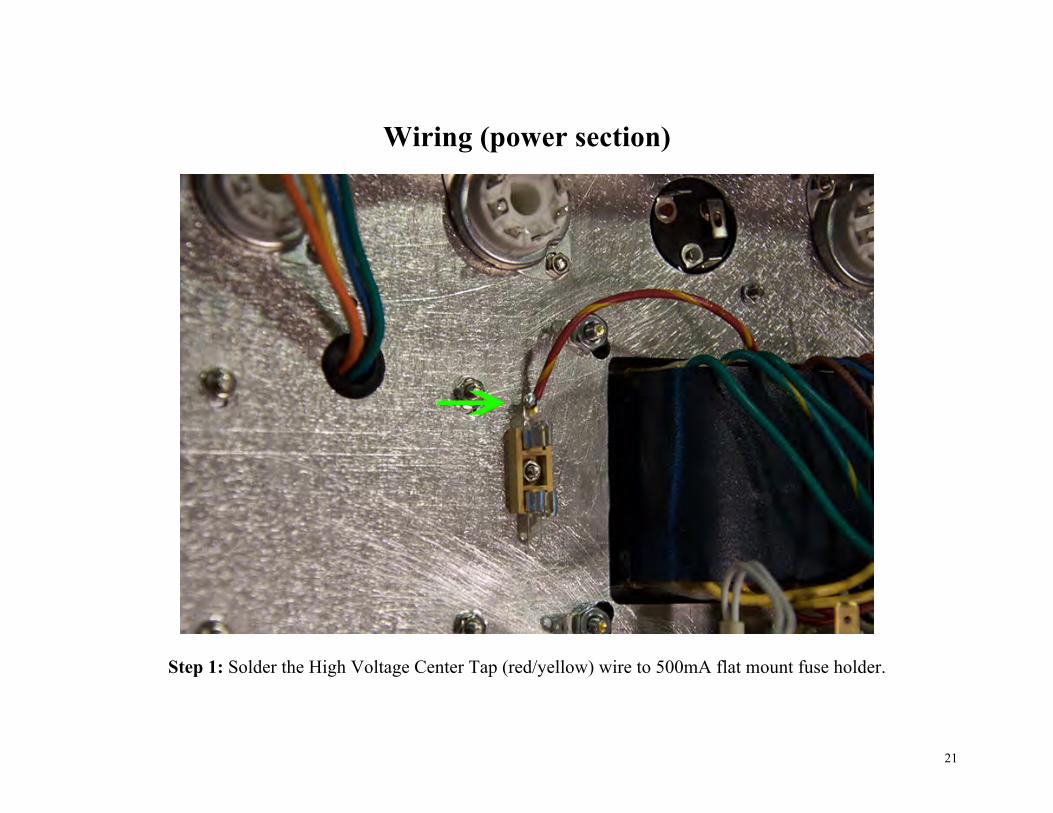
Step 1: Solder the High Voltage Center Tap (red/yellow) wire to 500mA flat mount fuse holder.
22
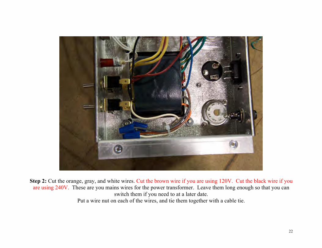
Step 2: Cut the orange, gray, and white wires. Cut the brown wire if you are using 120V. Cut the black wire if you are using 240V. These are you mains wires for the power transformer. Leave them long enough so that you can
switch them if you need to at a later date. Put a wire nut on each of the wires, and tie them together with a cable tie.
23
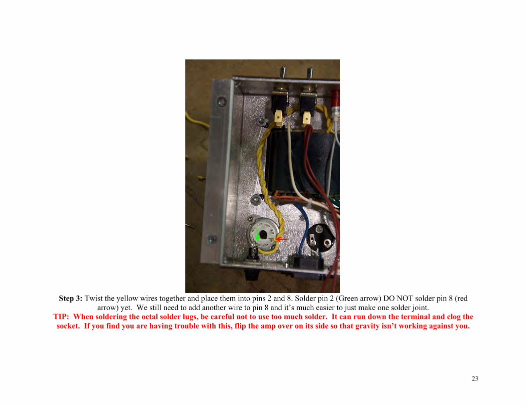
Step 3: Twist the yellow wires together and place them into pins 2 and 8. Solder pin 2 (Green arrow) DO NOT solder pin 8 (red
arrow) yet. We still need to add another wire to pin 8 and it’s much easier to just make one solder joint. TIP: When soldering the octal solder lugs, be careful not to use too much solder. It can run down the terminal and clog the socket. If you find you are having trouble with this, flip the amp over on its side so that gravity isn’t working against you.
24
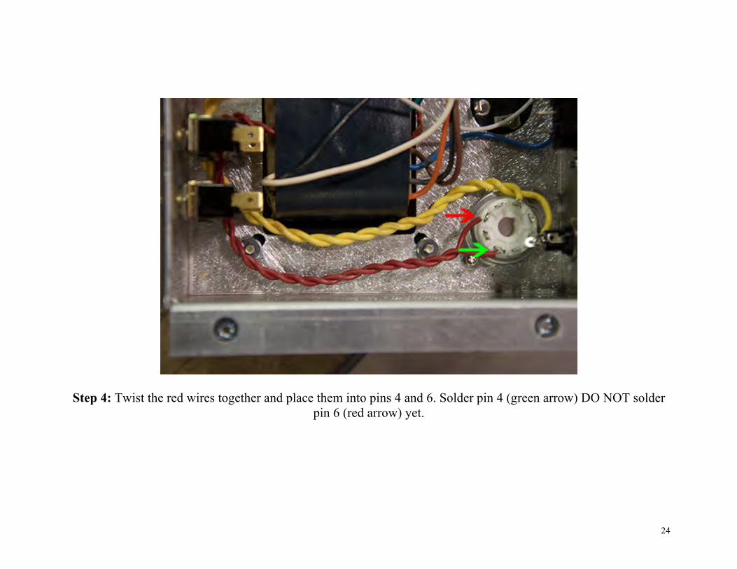
Step 4: Twist the red wires together and place them into pins 4 and 6. Solder pin 4 (green arrow) DO NOT solder pin 6 (red arrow) yet.

25
26
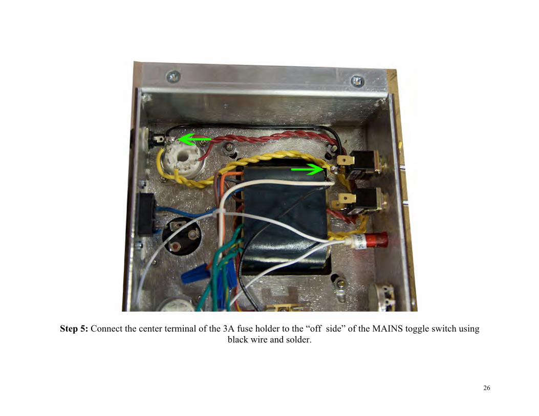
Step 5: Connect the center terminal of the 3A fuse holder to the “off side” of the MAINS toggle switch using black wire and solder.
27
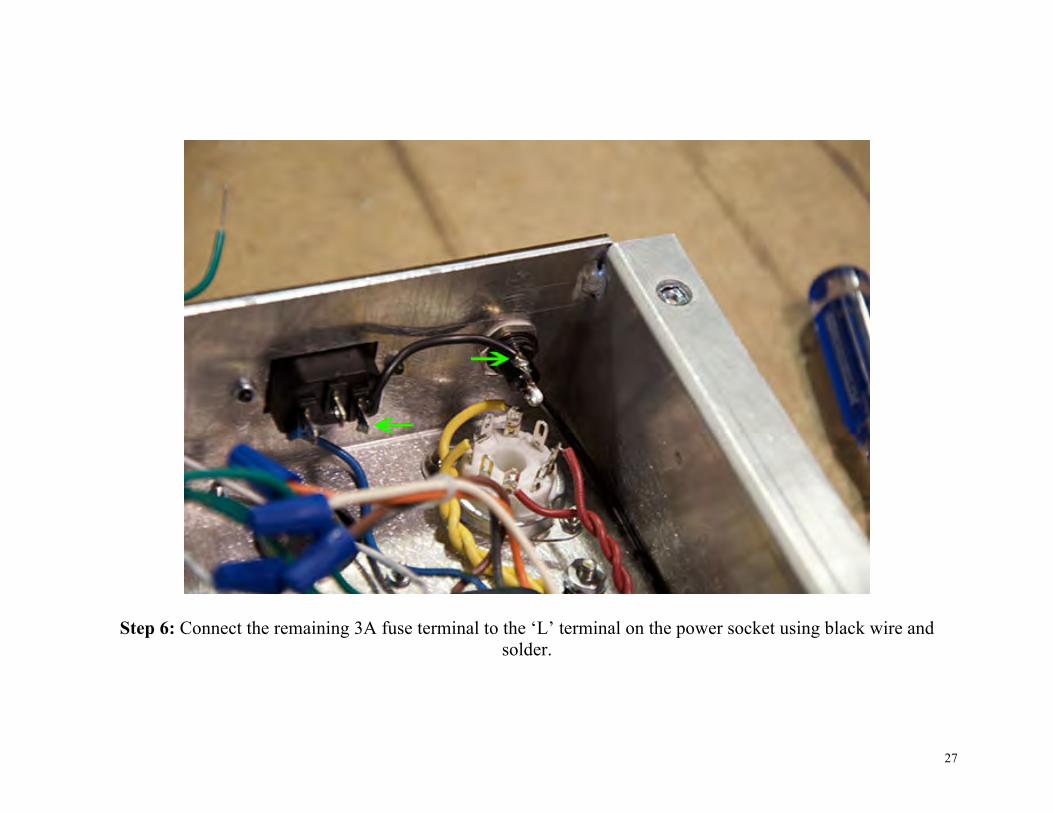
Step 6: Connect the remaining 3A fuse terminal to the ‘L’ terminal on the power socket using black wire and solder.
28
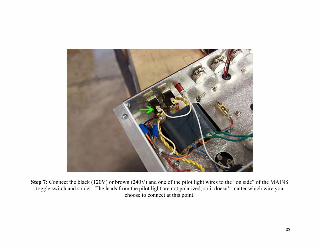
Step 7: Connect the black (120V) or brown (240V) and one of the pilot light wires to the “on side” of the MAINS toggle switch and solder. The leads from the pilot light are not polarized, so it doesn’t matter which wire you
choose to connect at this point.

29
Step 8: Connect the Blue (common) and remaining pilot wire to the ‘N’ terminal of the power socket and solder.

30
Step 9: Connect pin 8 of the rectifier socket to the “off side” of the standby toggle switch and solder both points. Remember that there should already be a yellow wire inserted into pin 8. This step is why we did not solder that
till now.

31
Step 10: Install 32uF+32uF capacitor as shown. You will use the remaining capacitor retainer, M3 nut, and 3 x M3 screws just like you did for the 16uF + 16uF capacitor.

32
Step 11: Connect the red terminal on the 32uF+32uF cap to the “on side” of the standby toggle switch (with a piece of red wire), black choke wire, and brown output transformer wire (red arrow) as shown. The choke will
have 2 black leads. These are not polarized so it does not matter which black choke wire you chose for this step.

33
Step 12: Connect both negative terminals of the two mounted electrolytic capacitors, the green/yellow CT wire (red arrow), and the AC power socket ground terminal to terminal washer mounted to the power transformer
closest to the tube side of the chassis.
34
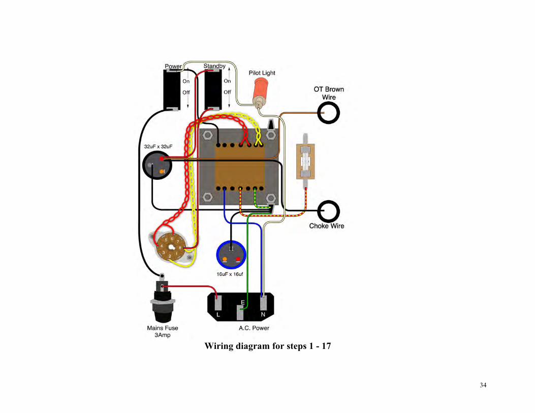
Wiring diagram for steps 1 - 17

35
Step 13: Add bus wire to the speaker jacks. Solder where the green arrows are pointing. Do not solder where the red arrows are pointing.

36
Step 14: Connect the yellow output transformer wire (Common) to the sleeve bus and solder.

37
Step 15: Connect the orange, green, and blue output transformer wires to the rotary switch as shown and solder.
38
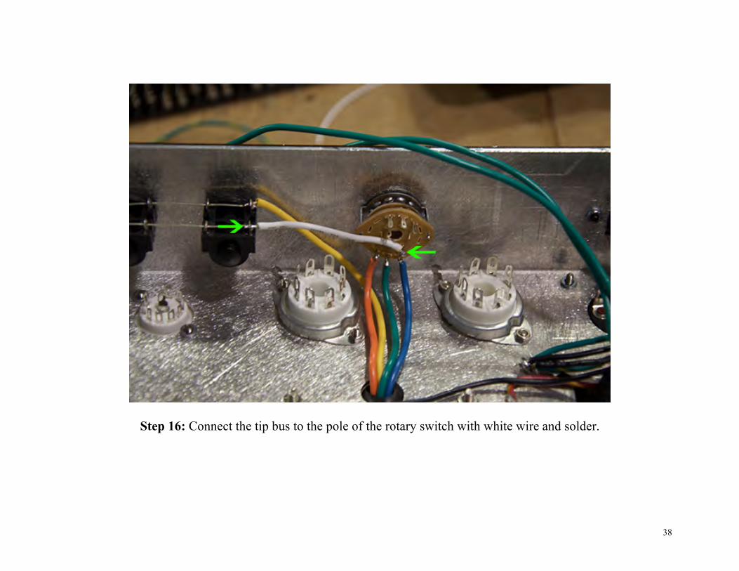
Step 16: Connect the tip bus to the pole of the rotary switch with white wire and solder.
39
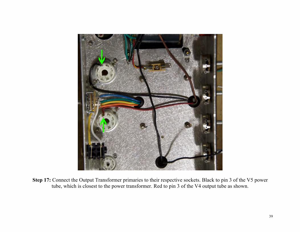
Step 17: Connect the Output Transformer primaries to their respective sockets. Black to pin 3 of the V5 power tube, which is closest to the power transformer. Red to pin 3 of the V4 output tube as shown.

40
Step 18: Connect a 1 ohm 1 Watt resistor from pins 1 & 8 of the V5 power tube (tube closest to the power transformer) to the terminal ring (page 13) and solder. It is difficult to see in the picture, but one end of the resistor is threaded through both pins 1 & 8.

41
Step 19: Repeat the previous step for the V4 power tube, but this time, also add a black wire to the terminal ring. Connect the other end of the black wire to the remaining unsoldered lug on the speaker jacks. You should now
have all of the lugs on the speaker jacks soldered.

42
Step 20: Connect the 6.3V heater wires from the power transformer to the filament pins of the power and preamp tubes. Start with the power tubes. One green wire goes to pin 2, the other to pin 7 of each power tube. It does not
matter which green wire goes to which pin. Insert the wires into the their solder terminals. Before you solder, insert another length of green wire into those same solder terminals to connect to the next tube. The heater wires
will “daisy chain” to all the tubes.

43
Step 21: Continue daisy chaining the heater wire to the pre amp tubes. Pre amp tube filament pins are 9 and 4/5. You will need to jumper pins 4 and 5 if you elected not to crimp them together earlier.

44
Step 22: Connect the two 470 ohm 2Watt resistors between pins 4 and 6 of the power tubes as shown. Be sure to only solder pin 4 (green arrow).

45
Step 23: Jumper pins 6 of both power tubes together with brown wire as shown. Insert one end of the 1K 2Watt resistor into pin 6 of the V4 power tube (red arrow). Leave the other end hanging out. Solder pins 6 of both
power tube sockets now.

46
Wiring diagram for steps 18 - 28

47
Step 24: Connect a bare bus wire to the back of the potentiometers as shown. We will refer to this as the “ground bus”. If you are having trouble connecting the bus wire to the back of the potentiometers, you can rough up the
backs with some emery cloth or a file, this should help with solder adhesion.
48
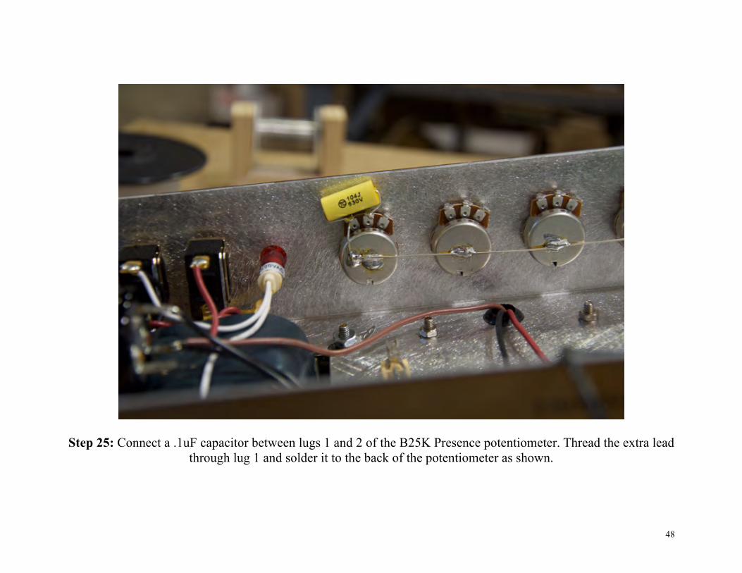
Step 25: Connect a .1uF capacitor between lugs 1 and 2 of the B25K Presence potentiometer. Thread the extra lead through lug 1 and solder it to the back of the potentiometer as shown.
49
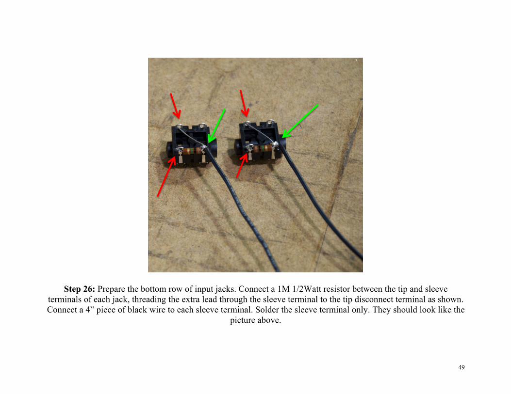
Step 26: Prepare the bottom row of input jacks. Connect a 1M 1/2Watt resistor between the tip and sleeve terminals of each jack, threading the extra lead through the sleeve terminal to the tip disconnect terminal as shown. Connect a 4” piece of black wire to each sleeve terminal. Solder the sleeve terminal only. They should look like the
picture above.

50
Step 27: Use ¾” of bus wire to connect the sleeve terminal of the other input jacks to the tip disconnect terminal as
shown. Only solder the terminals with green arrows.
51
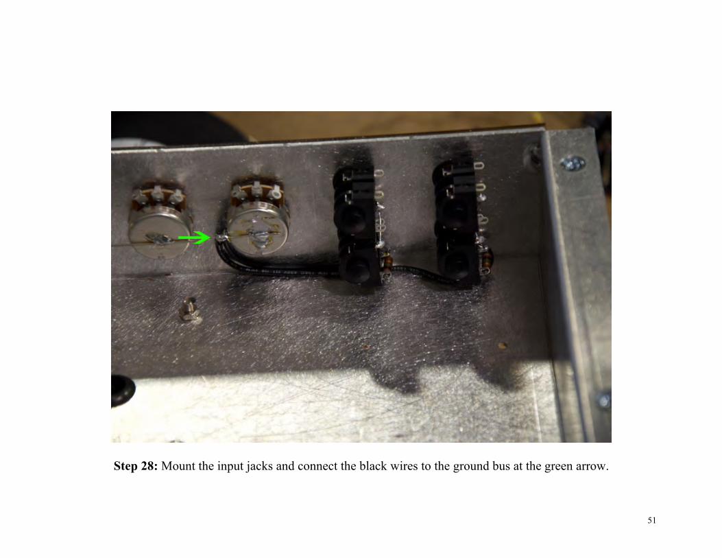
Step 28: Mount the input jacks and connect the black wires to the ground bus at the green arrow.

52
Step 29: Connect the remaining terminal of the ½ amp fuse holder and the ground bus to the last terminal washer mounted to the power transformer and solder at the green arrows.

53
wiring diagram for steps 29 - 34

54
Populating the Circuit Board
Step 1: Run bus wire along lower tier of the 3 turret lugs as shown.

55
56
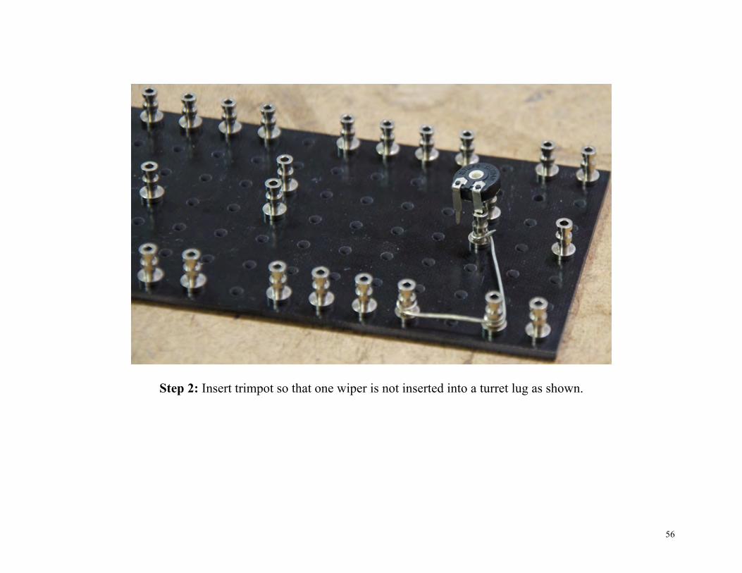
Step 2: Insert trimpot so that one wiper is not inserted into a turret lug as shown.
57
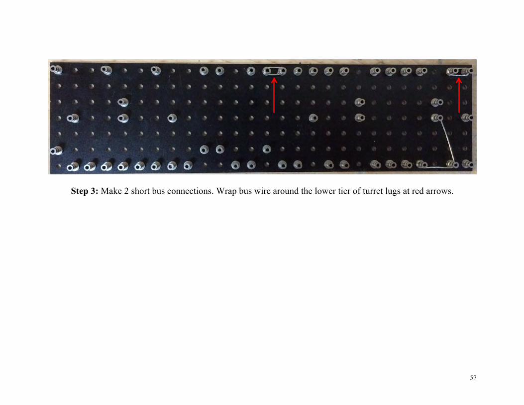
Step 3: Make 2 short bus connections. Wrap bus wire around the lower tier of turret lugs at red arrows.

58
Step 4: Insert all components into circuit board. Insert leads into openings of turret lugs. DO NOT solder the end of the 8K2 2Watt resistor (red arrow). Solder all the other turret lugs and bus wire. It is easier to solder the bus
wire connections first. Do not use too much solder. It will fill up the turret lugs and run out through the other side. If you are having problems with this, tilt the circuit board slightly or on its side so that you are not fighting against
gravity as hard.

59
Drawing of component placement. DO NOT solder the red arrow yet.
60
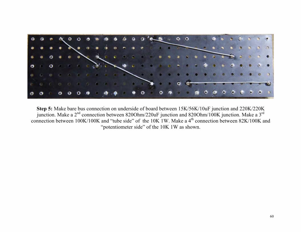
Step 5: Make bare bus connection on underside of board between 15K/56K/10uF junction and 220K/220K junction. Make a 2nd connection between 820Ohm/220uF junction and 820Ohm/100K junction. Make a 3rd
connection between 100K/100K and “tube side” of the 10K 1W. Make a 4th connection between 82K/100K and “potentiometer side” of the 10K 1W as shown.
61
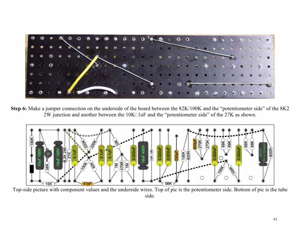
Step 6: Make a jumper connection on the underside of the board between the 82K/100K and the “potentiometer side” of the 8K2 2W junction and another between the 10K/.1uF and the “potentiometer side” of the 27K as shown.
Top-side picture with component values and the underside wires. Top of pic is the potentiometer side. Bottom of pic is the tube
side.
62
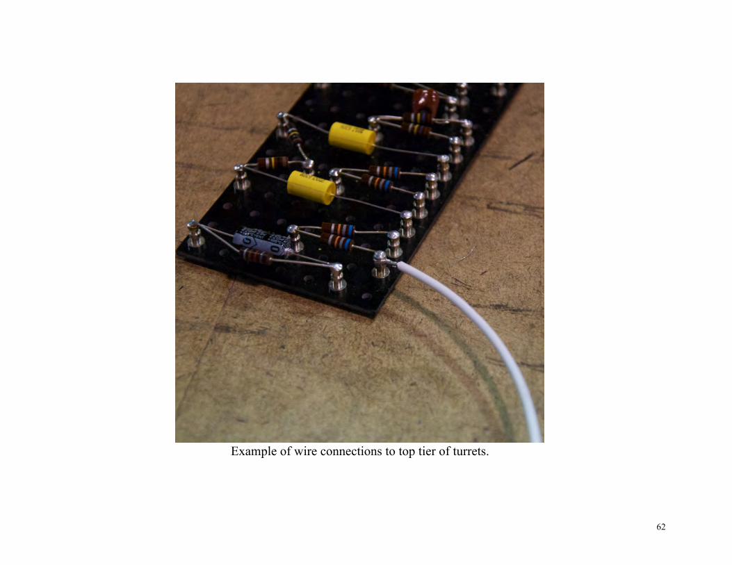
Example of wire connections to top tier of turrets.
63
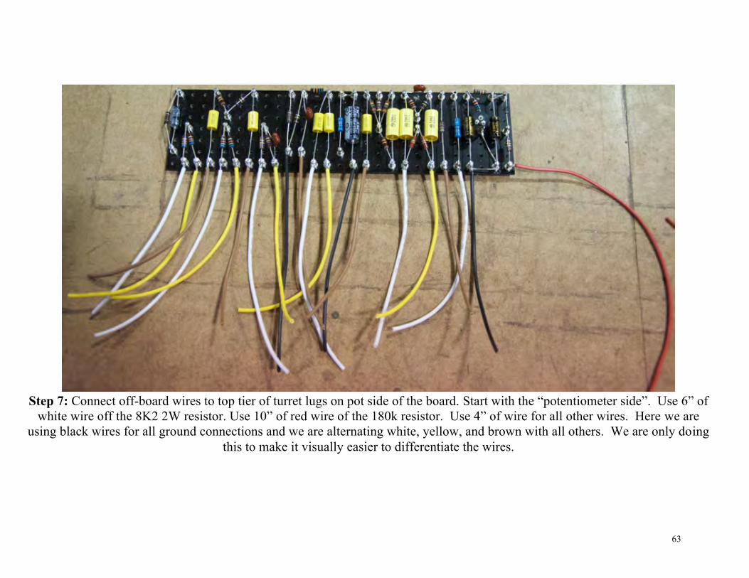
Step 7: Connect off-board wires to top tier of turret lugs on pot side of the board. Start with the “potentiometer side”. Use 6” of
white wire off the 8K2 2W resistor. Use 10” of red wire of the 180k resistor. Use 4” of wire for all other wires. Here we are using black wires for all ground connections and we are alternating white, yellow, and brown with all others. We are only doing
this to make it visually easier to differentiate the wires.

64
Step 8: Connect off board wires to the two 68K/68K junctions and 500pF/270K/270K junction. Thread the wires through the board as shown at the red arrows.

65
Step 9: Add the rest of the off-board wires to the “tube side” of the circuit board.

66
Step 10: add the 3 hex standoffs at the red arrows. Use M3 screws.
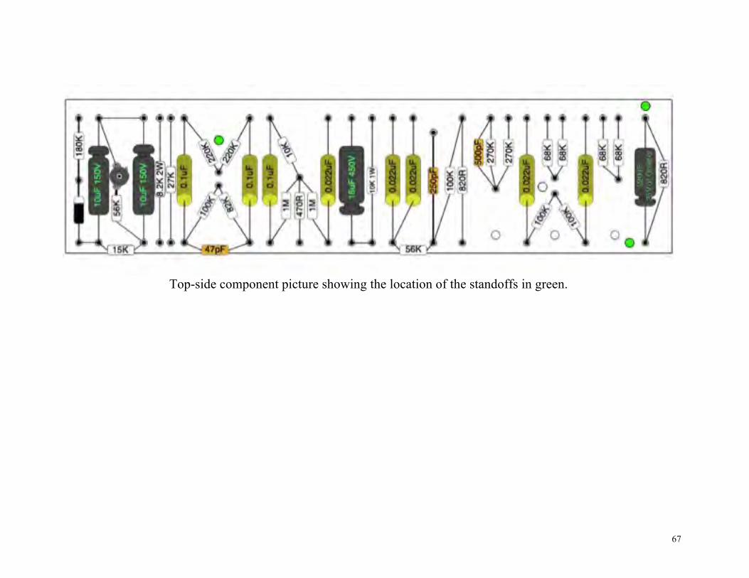
67
Top-side component picture showing the location of the standoffs in green.

68
Step 11: Mount the circuit board. 11 a: Run the white and yellow wires from the two 220K/.1uF junctions under the board so they stick out on the “tube side” (red
arrows). 11 b: Make sure you can get to the remaining choke wire and 1K 2Watt resistor (red arrows).

69
Wiring (Tube side)
Step 1: Connect the white and yellow wires from the previous step to pin5 (shown at green arrows).
A: White wire to V4 B: Yellow wire to V5

70
Step 2: Connect the open end of the 1K 2W, remaining choke wire, and 6” of red wire to the last unsoldered turret lug at red arrow.
WARNING!! A: DO NOT make wires/leads so long that they go through the turret lug and out of the other side. They may touch the
chassis and cause a short. B: DO NOT use too much solder. It may drip out the bottom and cause a short.

71
Step 3: Connect the red wire you just added in step 2 to the YELLOW terminal of the 32uF+32uF electrolytic capacitor (yellow arrow).

72
Step 4: Run a bus wire between pins 3 and 8 of V1. Solder pin 8, DO NOT solder pin 3 yet. Step 5: Wire V1. The off-board wires are laid out with the intention of progressing from left to right. Start with the brown wire
that connects to pin 3 and then work your way left to the yellow wire that connects to pin 6.

73
Step 6: Add the 100k resistor and jumper to V2. Thread one end of a 100K 1/2W resistor through pin 1 of V2. Bend the lead around and thread through pin 7. Insert the other end into pin 6. Solder pins 1 & 7 (Green arrows) DO NOT solder pin 6 (red
arrow).

74
Step 7: Make the rest of the off board connections to V2. Again, move from left to right.

75
Step 8: Run bus wire between pins 3 and 8 of V3. Solder pin 3, DO NOT solder pin 8 yet.
Step 9: Make the off board connections to V3 as shown. Solder the pins now.

76
Step 10: Connect the last off board wire from the 27K resistor to the same solder lug on the rotary switch as the blue 16 Ohm wire (green arrows).
There is not enough room to fit this wire into the lug, so simply tack solder it to the lug.

77
Wiring diagram for steps 1 – 10 Wiring Tube Side

78
Wiring (Potentiometer side)
Step 1: Connect the red wire from the 180K resistor to pin 6 of the V6 rectifier tube socket (green arrows).

79
Step 2: Connect the white wire from the 8K2 2Watt resistor to the RED terminal of the 16uF+16uF capacitor (green arrows).

80
Step 3: Connect all black wires (green arrows) to the ground bus.

81
Step 4: Connect the brown wire from the 27K to lug 3 of the Presence pot.

82
Step 5: Connect lug 1 of the Bass pot to lug 3 of the Middle pot as shown.

83
Step 6: Connect lug 1 of Middle, and both Loudness pots to the ground bus as shown.
84
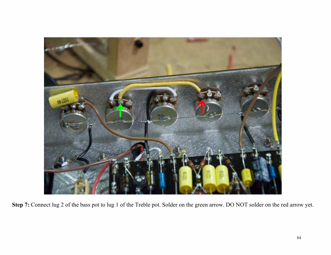
Step 7: Connect lug 2 of the bass pot to lug 1 of the Treble pot. Solder on the green arrow. DO NOT solder on the red arrow yet.

85
Step 8: Make the rest of the connections to the Middle and Treble pots.
86
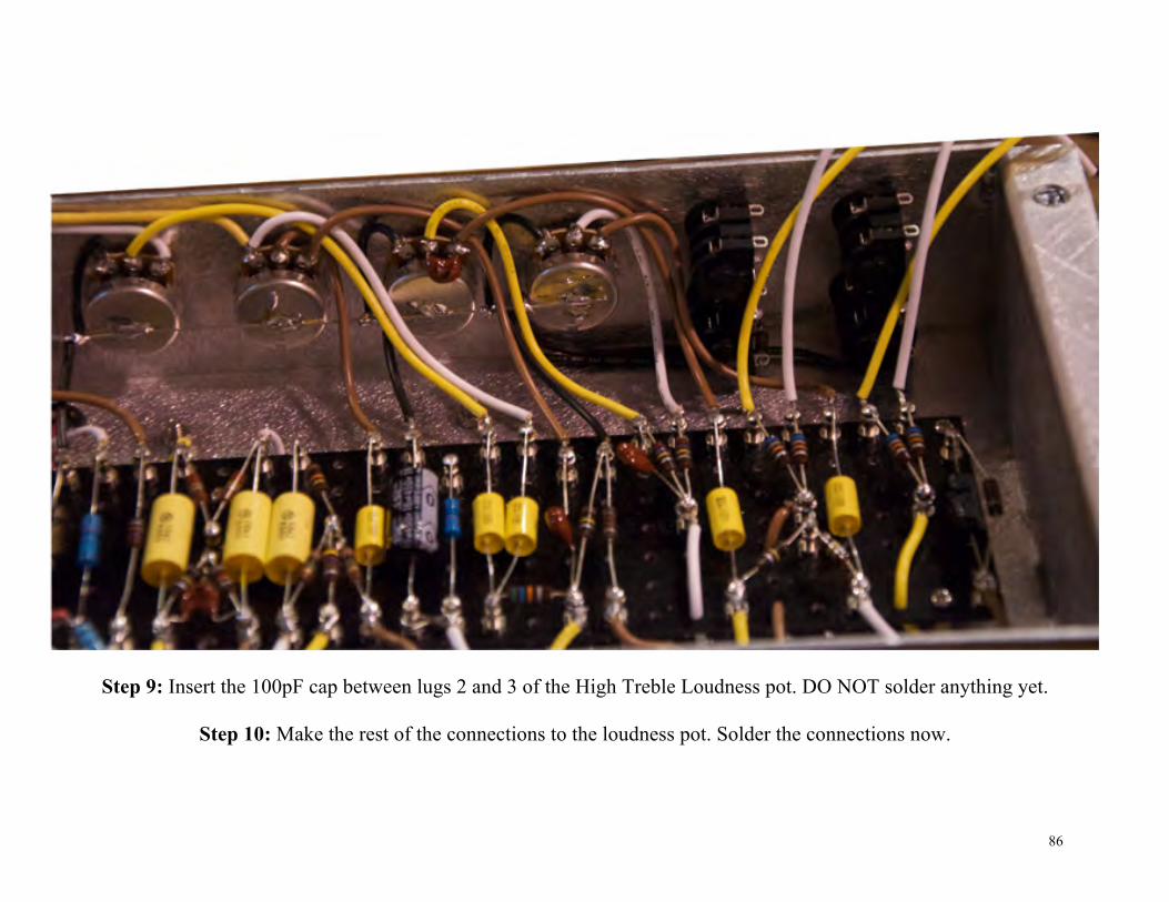
Step 9: Insert the 100pF cap between lugs 2 and 3 of the High Treble Loudness pot. DO NOT solder anything yet.
Step 10: Make the rest of the connections to the loudness pot. Solder the connections now.

87
Step 11: Use bare bus wire to connect the tip of the lower input jacks to the disconnect tip of the upper jack. Solder the lower jack at the green arrows. DO NOT solder the disconnect tip (red arrows).

88
Step 12: Connect the yellow wires to the tip terminals of the upper input jacks.

89
Step 13: Connect the white wires to the disconnect tip terminals.
90
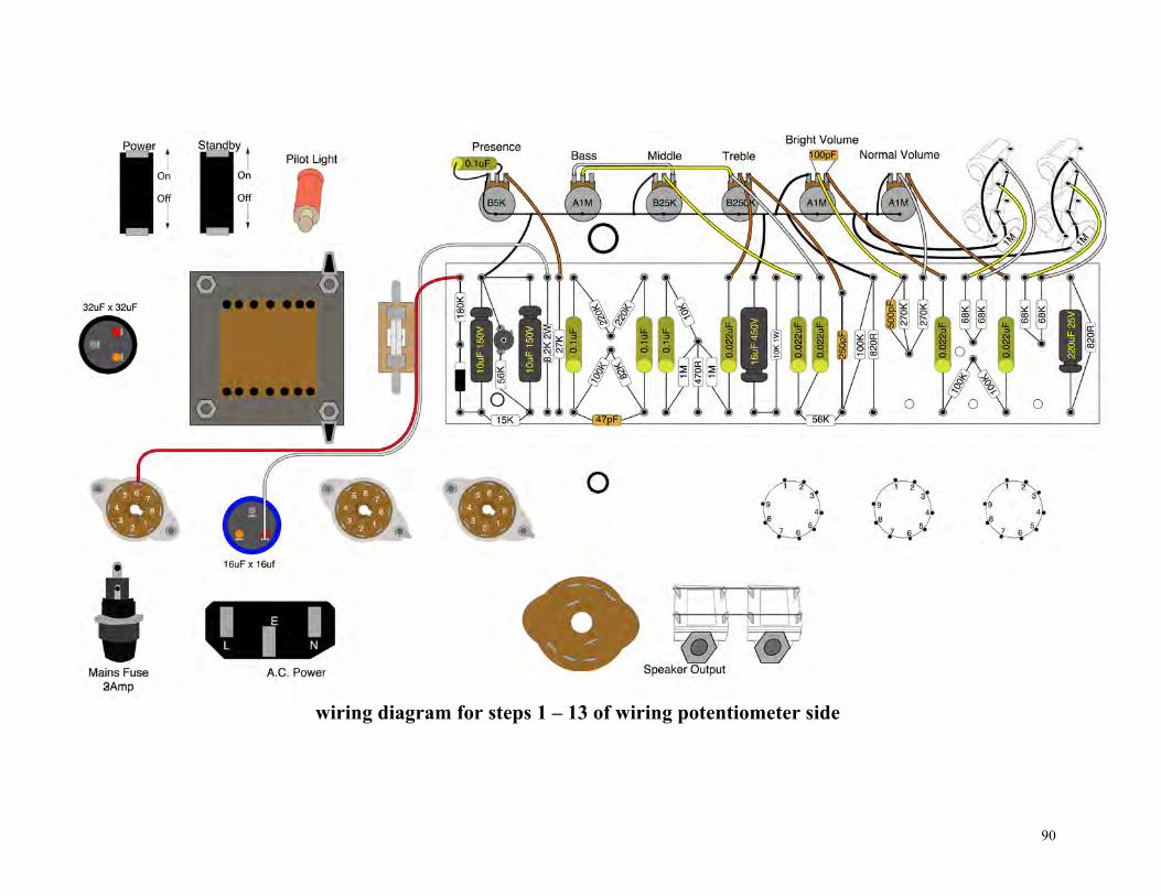
wiring diagram for steps 1 – 13 of wiring potentiometer side

91
120V Layout
Go to http://www.byocelectronics.com/jtm45-120v.pdf for high-res PDF.
92
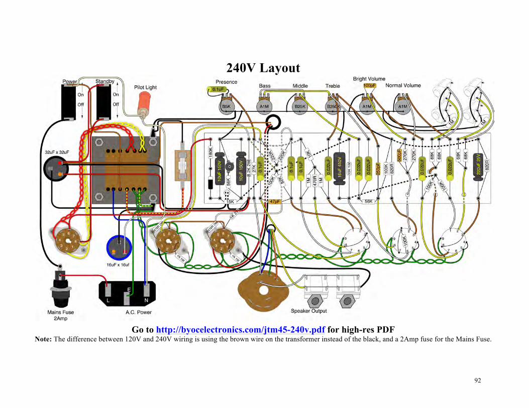
240V Layout
Go to http://byocelectronics.com/jtm45-240v.pdf for high-res PDF
Note: The difference between 120V and 240V wiring is using the brown wire on the transformer instead of the black, and a 2Amp fuse for the Mains Fuse.
93
Turning your amp on for the first time
Step 1: Make sure your AC power cord is NOT plugged in. Do NOT install any of the tubes yet. Do not plug a speaker into the speaker jack. Do not plug any instruments into the input jacks. If at any point in this process, you smell smoke, see sparks, or hear any loud electrical hum noises, immediately pull the AC power cord from the wall socket.
Step 2: Do not test your amp on a metal table or any surface that can conduct electricity. Situate yourself and your amp so that the AC power outlet you will be using is within arm's length.
Step 3: Install your amplifier chassis into the cabinet or enclosure that you should have. You should never apply power to the amplifier while it is not inside its cabinet or enclosure. If you insist on supplying power to the amplifier while it is not inside its cabinet or enclosure, the safest way to do so is with the chassis laying on a non-conductive, flame retardant surface with the transformer side facing down and the open side of the chassis facing up, making sure that no foreign objects (especially any of your body parts) are touching any part of the amp.
Step 4: Install the 3A (120v) or 2A (240v) fuse into the panel mounted fuse holder on the back of the chassis. You can tell the 2A or 3A fuse apart from the 500mA fuse because the 2A or 3A fuse will have a small “2” or “3” printed on it and the 500mA fuse will have “500” printed on it somewhere. You can also tell because the the 2A or 3A fuse will have a thicker conductive wire running through the middle of it than the 500mA.
Step 5: Turn the amplifier's power switch on, but still do not plug the power cord in yet. Step 6: Orient the amp so that you can see the indicator light. When you plug the power cord into the AC power supply, you should be able to see the indicator light come on immediately. This means, at the very least, AC power is getting to the power transformer and that the power transformer is working.

94
Step 7: Turn the mains switch off and unplug the power cord from the wall socket.
Step 8: With the mains switch off and the AC power cord unplugged from the wall, now install the 500mA fuse into the flat mount fuse holder and install the GZ34 rectifier tube into the V6 tube socket. When testing your amp voltages, always keep one hand in your pocket and wear shoes with rubber soles. This doesn't reduce the risk of electrocution, but it will reduce the amount of damage that will be done if you get do electrocuted. It won't make you impervious to electrocution, but the less “grounded” you are, the less the amount of current that will be able to flow through your body. Doing things like going barefoot or holding onto a metal drain pipe with your free hand while working with electricity won't increase the risk of electrocution, but they will increase how well you conduct current to ground, and that increases the amount of damage you can do to yourself if you are electrocuted.
GZ43 KT66
ECC83

95
Step 9: Plug the AC cord into the wall socket. Make sure the standby switch is in the “standby” position. Turn the mains switch on. The rectifier tube should start to warm up and glow. Hopefully you know that vacuum tubes (especially the rectifier tube) get very hot once they are warmed up. You must allow adequate time to pass for them to cool off before you attempt to touch them. If you measure the voltage at the red terminal of the 32uFx32uF electrolytic capacitor, you should read approximately 450VDC. To test the rectified DC voltage, first set your meter to test DC voltage 500V or greater. Then connect the black probe to chassis ground. Then touch the red probe to the various test points Step 10: Turn the standby toggle switch to the on position. You should read 440VDC at position B (yellow terminal of the 32uFx32uF capacitor), 380VDC at position C (red terminal of the 16uFx16uF electrolytic capacitor), and 310VDC at position D (the positive end of the 16uF/450V electrolytic capacitor on the circuit board). These are approximate voltages and the circuit isn’t actually under full load yet, so don’t be alarmed if your actual readings are +/- 20V. Step 11: Unplug the AC power cord from the wall and turn the toggle switches to their off positions. Step 12: VERY IMPORTANT BEFORE YOU ADD THE KT66 TUBES!!! Be sure to plug a speaker into the speaker jack. You should never turn your amp on when the power tube is installed without the proper speaker load. Doing so will damage your output transformer. Plug a speaker into the speaker jack. Make sure the impedance rotary switch is set to the correct impedance for the speaker you are using. The speaker should be able to handle 30watts. Step 13: Install the KT66 tubes into their sockets. Plug the AC power cord into the wall. Turn the mains toggle switch on. You should see the rectifier tube and KT66s begin to heat up and glow.
96
Step 14: Unplug the AC power cord from the wall and turn the toggle switches to their off positions. Step 15: Install the ECC83 tubes. Plug the AC power cord into the wall. Turn the mains toggle switch on. Keep the standby switch off. You should see all the tubes start to heat up and glow. Step 16: Turn all the knobs down and take the amp out of standby. You should hear a soft white noise start to come out of the speaker. Step 17: Return the amp to standby.
BIASING Step 18: OK. You need to bias your amp correctly before you start playing. This is very important. If you have it biased too “hot” you can damage the KT66 tubes or burn out one of the resistors. If you have it biased too “cool”, it just won’t sound very good. You adjust the bias by turning the trimpot on the circuit board. You will need a very small hex wrench or screwdriver (depending upon the type of trimpot supplied with your kit). Test the bias voltage by taking a reading at pin 1 or 8 of either power tubes. You’ll probably want to set your meter to its lowest voltage range if it isn’t an auto-ranging meter…probably the 200mVDC setting. Adjust the bias trimpot so that you read 39mV at pins 1 & 8 of both power tubes. Step 19: Plug a guitar in. Take the amp out of standby. Take her for a test drive.

97
Operating Overview
Front Panel
This should be pretty standard stuff for the most part, but the JTM45 does have some peculiarities.
You probably won’t ever want to use the HIGH TREBLE channel unless you are jumpering it with the normal channel. It will typically be much too bright for most peoples’ taste.
Loudness 1 only works if you have an input in either of the two “1” inputs. Loudness 2 only works if you have an input in either of the two “2” inputs.
Jumpering: You can use a patch cable to connect one of the “1” inputs to one of the “2” inputs. Plug your instrument into either of the open “1” or “2” inputs. This will allow you to blend both channels. Many people think this is how you should always run a JTM45. That’s a matter of opinion, but it is certainly the best way to get the most gain out of the amp.

98
Back Panel
Power Cord Socket: Plug your power cord in to this. Fuse Holder: This is where the fuse goes. It says 2AMP because, but be sure to use a 3A if you are in a 120VAC country. Impedance Selector: Set this 3 position switch to match the impedance of the speaker(s) you are using. Speaker Jack: Insert speaker cable here. Use speakers rated for 30 watts or higher.
99
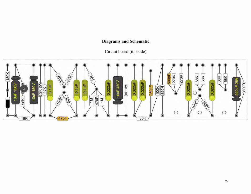
Diagrams and Schematic
Circuit board (top side)
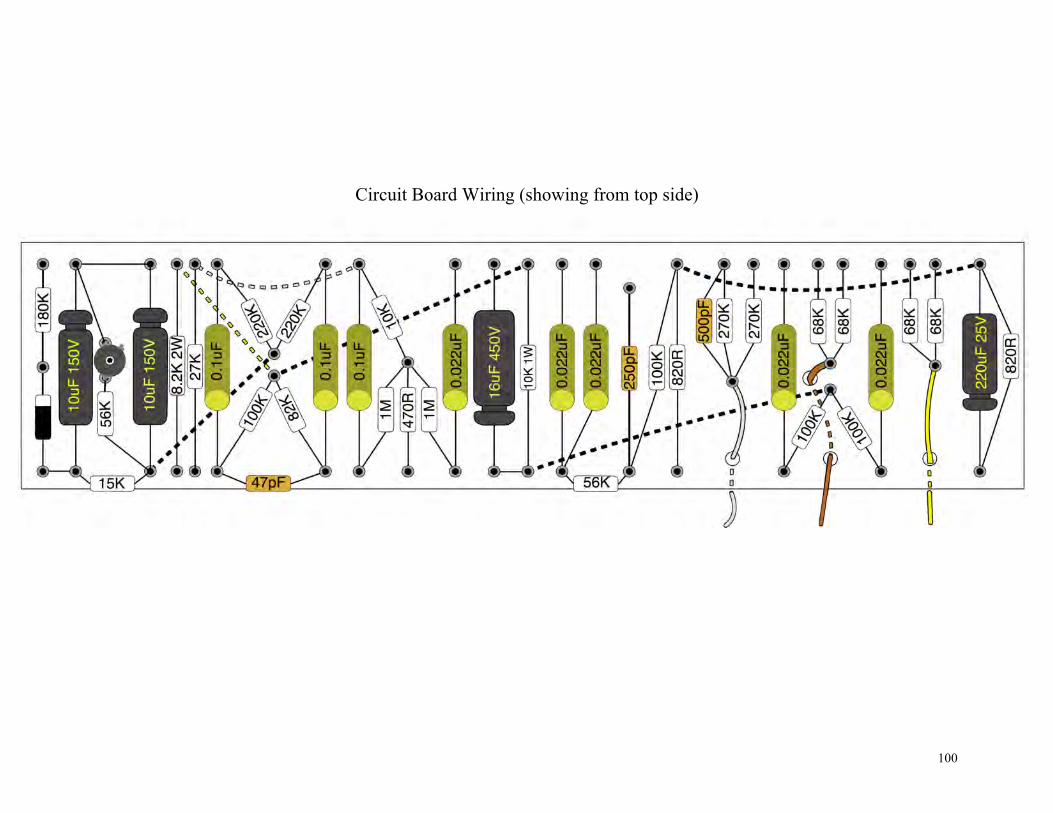
100
Circuit Board Wiring (showing from top side)

101
Heater Wiring for hi res pdf go to http://www.byocelectronics.com/jtm45heater.pdf
102
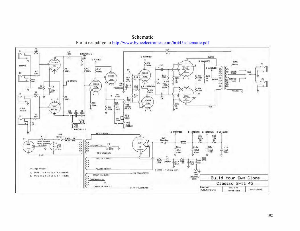
Schematic For hi res pdf go to http://www.byocelectronics.com/brit45schematic.pdf

103
For technical support, visit www.byocelectronics.com/board
Written by: N.W. Kenning & K. Vonderhulls
Artwork & Photography by:
N.W. Kenning & K. Vonderhulls
Copyright BYOC, Inc. 2015