brit science 2008
DESCRIPTION
kod braille sainsTRANSCRIPT

BRAILLE AUTHORITY OF THE UNITED KINGDOM
BRAILLE SCIENCE NOTATION
Royal National Institute of Blind PeopleBakewell Road, Orton SouthgatePeterborough, Cambridgeshire
PE2 6XU2008
© Braille Authority of the United Kingdom 1989, 2008
Registered Charity No. 1001157
Printed by RNIB, Peterborough 2008
i
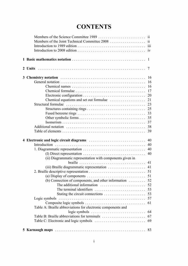
CONTENTS
Members of the Science Committee 1989 . . . . . . . . . . . . . . . . . . . . . . . . . iiMembers of the Joint Technical Committee 2008 . . . . . . . . . . . . . . . . . . . iiIntroduction to 1989 edition . . . . . . . . . . . . . . . . . . . . . . . . . . . . . . . . . . . . iiiIntroduction to 2008 edition . . . . . . . . . . . . . . . . . . . . . . . . . . . . . . . . . . . . iv
1 Basic mathematics notation . . . . . . . . . . . . . . . . . . . . . . . . . . . . . . . . . . . . . . . 1 2 Units . . . . . . . . . . . . . . . . . . . . . . . . . . . . . . . . . . . . . . . . . . . . . . . . . . . . . . . . . 7
3 Chemistry notation . . . . . . . . . . . . . . . . . . . . . . . . . . . . . . . . . . . . . . . . . . . . . 16General notation . . . . . . . . . . . . . . . . . . . . . . . . . . . . . . . . . . . . . . . . . . . . . 16
Chemical names . . . . . . . . . . . . . . . . . . . . . . . . . . . . . . . . . . . . . . . 16Chemical formulae . . . . . . . . . . . . . . . . . . . . . . . . . . . . . . . . . . . . . 17Electronic configuration . . . . . . . . . . . . . . . . . . . . . . . . . . . . . . . . . 20Chemical equations and set out formulae . . . . . . . . . . . . . . . . . . . 21
Structural formulae . . . . . . . . . . . . . . . . . . . . . . . . . . . . . . . . . . . . . . . . . . 23Structures containing rings . . . . . . . . . . . . . . . . . . . . . . . . . . . . . . . 25Fused benzene rings . . . . . . . . . . . . . . . . . . . . . . . . . . . . . . . . . . . . 33Other symbolic forms . . . . . . . . . . . . . . . . . . . . . . . . . . . . . . . . . . . 35Isomerism . . . . . . . . . . . . . . . . . . . . . . . . . . . . . . . . . . . . . . . . . . . . 37
Additional notation . . . . . . . . . . . . . . . . . . . . . . . . . . . . . . . . . . . . . . . . . . 38Table of elements . . . . . . . . . . . . . . . . . . . . . . . . . . . . . . . . . . . . . . . . . . . . 39
4 Electronic and logic circuit diagrams . . . . . . . . . . . . . . . . . . . . . . . . . . . . . . 40Introduction . . . . . . . . . . . . . . . . . . . . . . . . . . . . . . . . . . . . . . . . . . . . . . . . 401. Diagrammatic representation . . . . . . . . . . . . . . . . . . . . . . . . . . . . . . . . . 40
(I) Direct representation . . . . . . . . . . . . . . . . . . . . . . . . . . . . . . . . . 40(ii) Diagrammatic representation with components given in
braille . . . . . . . . . . . . . . . . . . . . . . . . . . . . . . . . . . . 41(iii) Braille diagrammatic representation . . . . . . . . . . . . . . . . . . . . 41
2. Braille descriptive representation . . . . . . . . . . . . . . . . . . . . . . . . . . . . . . 51(a) Display of components . . . . . . . . . . . . . . . . . . . . . . . . . . . . . . . 51(b) Connection of components, and other information . . . . . . . . . 52
The additional information . . . . . . . . . . . . . . . . . . . . . . . . 52The terminal identifiers . . . . . . . . . . . . . . . . . . . . . . . . . . . 53Stating the circuit connections . . . . . . . . . . . . . . . . . . . . . . 53
Logic symbols . . . . . . . . . . . . . . . . . . . . . . . . . . . . . . . . . . . . . . . . . . . . . . 57Composite logic symbols . . . . . . . . . . . . . . . . . . . . . . . . . . . . . . . . 61
Table A: Braille abbreviations for electronic components andlogic symbols . . . . . . . . . . . . . . . . . . . . . . . . . . . . . 64
Table B: Braille abbreviations for terminals . . . . . . . . . . . . . . . . . . . . . . . 67Table C: Electronic and logic symbols . . . . . . . . . . . . . . . . . . . . . . . . . . . 69
5 Karnaugh maps . . . . . . . . . . . . . . . . . . . . . . . . . . . . . . . . . . . . . . . . . . . . . . . . 83

ii
MEMBERS OF THE SCIENCE COMMITTEE 1989
J. A. Allnut (Chairman), Central Electricity Research LaboratoryG. W. Corfield, Royal National College for the BlindT. K. Devonald, Royal National College for the BlindR. L. Gorton, British TelecomM. J. GriffinMiss M. P. L. Kingsley, RNIBMrs R. M. Kirkwood, New College WorcesterT. D. Maley, RNIB Vocational College, LoughboroughS. J. Minett, New College WorcesterN. Octon, RNIBS. J. Phippen, RNIBW. B. L. Poole, Chairman Braille Authority of the United KingdomT. Robinson, GEC AvionicsM. Townsend, Torch Trust
MEMBERS OF THE JOINT TECHNICALCOMMITTEE 2008
D. Boden, Braille Computer Association of the BlindN. Brown, New College WorcesterS. A. Clamp, Visual Impairment and Special Needs Advice (VISpA)S. J. Phippen, RNIB PeterboroughW. B. L. Poole, Chairman Braille Authority of the United KingdomD. Spybey, New College WorcesterP. Southall, Dorton House SchoolC. Stonehouse, New College WorcesterP. Tooze, PiaM. E. Townsend, Torch Trust for the BlindR. West, Braille Computer Association of the Blind

iii
INTRODUCTION TO 1989 EDITION
It is almost thirty years since the publication of the previous edition of the BrailleScience Notation, and the need for a new edition has become increasingly pressing, both inorder to update the braille techniques, and to keep pace with the ever changing symbolism ofscience. The revision was undertaken in stages, and in fact the section on chemistry notationwas released as early as December 1985, in order to allow those parts of the previous editionmost at odds with current practice to be dispensed with promptly.
This work was carried out in parallel with the revision of the Braille MathematicsNotation (published in 1987), and the two publications are now entirely consistent. Indeed,the section on unit abbreviations is identical to the corresponding section in the BrailleMathematics Notation, and was considered jointly by both committees. It should beemphasised that the transcription of scientific text draws heavily upon the mathematics code,and for this reason a short summary is presented in the first section, and the section on unitabbreviations follows. Other sections give additional techniques and guidance which may berequired for specific fields.
The sections on chemistry notation and electronic and logic circuits have been entirelyrevised in order to resolve problems which had emerged with the previous code, to improvethe presentation, and to extend and update the notation. It should be noted that as a result,important changes have been made to the basic methods given for structural formulae inchemistry, and for electronic and logic circuit diagrams. It is recommended that when thespecial techniques given here for diagrammatic structural formulae and circuit diagrams areused in transcription work, the reader should be forewarned by the insertion of a notereferring to the Braille Science Notation 1989 for explanation of the techniques andabbreviations used. It is also worth emphasising here that these special techniques forrepresenting such diagrams are intended as a standard resource for use when it isadvantageous to do so; direct diagrammatic representation is still to be regarded as a basictechnique for such cases.
We are fortunate that we have been able to set this edition on computer. It isanticipated that in future it will be possible to keep the Braille Science Notation up to dateand meeting current needs, and that any errors or omissions can be corrected promptly.
iv
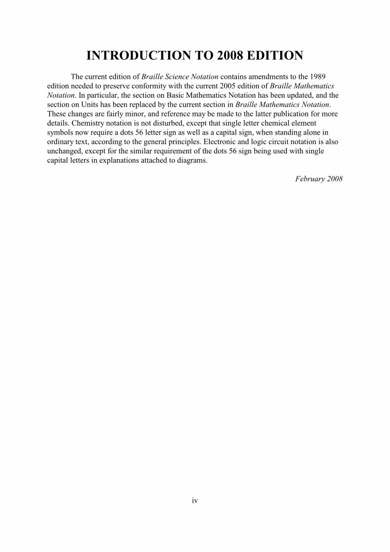
INTRODUCTION TO 2008 EDITION
The current edition of Braille Science Notation contains amendments to the 1989edition needed to preserve conformity with the current 2005 edition of Braille MathematicsNotation. In particular, the section on Basic Mathematics Notation has been updated, and thesection on Units has been replaced by the current section in Braille Mathematics Notation.These changes are fairly minor, and reference may be made to the latter publication for moredetails. Chemistry notation is not disturbed, except that single letter chemical elementsymbols now require a dots 56 letter sign as well as a capital sign, when standing alone inordinary text, according to the general principles. Electronic and logic circuit notation is alsounchanged, except for the similar requirement of the dots 56 sign being used with singlecapital letters in explanations attached to diagrams.
February 2008
1
BRAILLE SCIENCE NOTATION
1BASIC MATHEMATICS NOTATION
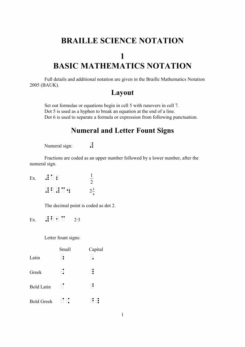
Full details and additional notation are given in the Braille Mathematics Notation2005 (BAUK).
Layout
Set out formulae or equations begin in cell 5 with runovers in cell 7.Dot 5 is used as a hyphen to break an equation at the end of a line.Dot 6 is used to separate a formula or expression from following punctuation.
Numeral and Letter Fount Signs
Numeral sign: #
Fractions are coded as an upper number followed by a lower number, after thenumeral sign.
Ex. #a2
#b#c4
The decimal point is coded as dot 2.
Ex. #b1c 2@3
Letter fount signs:
Small Capital
Latin ; ,
Greek . _
Bold Latin @ ^
Bold Greek @. ^_
Basic Mathematics Notation
2
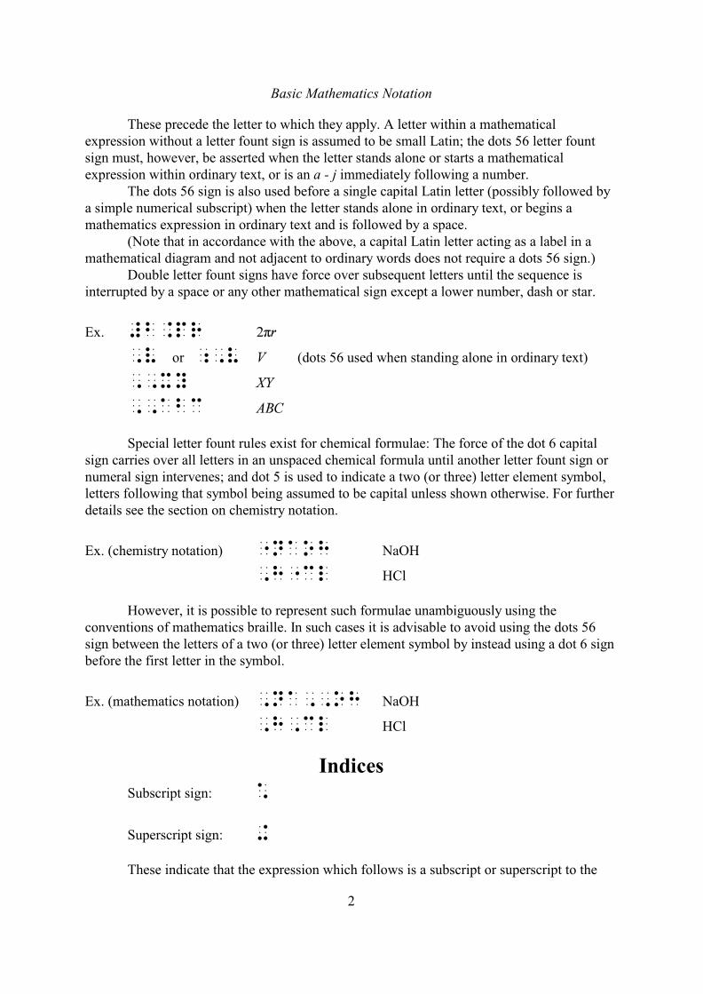
These precede the letter to which they apply. A letter within a mathematicalexpression without a letter fount sign is assumed to be small Latin; the dots 56 letter fountsign must, however, be asserted when the letter stands alone or starts a mathematicalexpression within ordinary text, or is an a - j immediately following a number.
The dots 56 sign is also used before a single capital Latin letter (possibly followed bya simple numerical subscript) when the letter stands alone in ordinary text, or begins amathematics expression in ordinary text and is followed by a space.
(Note that in accordance with the above, a capital Latin letter acting as a label in amathematical diagram and not adjacent to ordinary words does not require a dots 56 sign.)
Double letter fount signs have force over subsequent letters until the sequence isinterrupted by a space or any other mathematical sign except a lower number, dash or star.
Ex. #b.pr
,v or ;,v (dots 56 used when standing alone in ordinary text)
,,xy
,,abc
Special letter fount rules exist for chemical formulae: The force of the dot 6 capitalsign carries over all letters in an unspaced chemical formula until another letter fount sign ornumeral sign intervenes; and dot 5 is used to indicate a two (or three) letter element symbol,letters following that symbol being assumed to be capital unless shown otherwise. For furtherdetails see the section on chemistry notation.
Ex. (chemistry notation) "naoh NaOH
,h"cl HCl
However, it is possible to represent such formulae unambiguously using theconventions of mathematics braille. In such cases it is advisable to avoid using the dots 56sign between the letters of a two (or three) letter element symbol by instead using a dot 6 signbefore the first letter in the symbol.
Ex. (mathematics notation) ,na,,oh NaOH
,h,cl HCl
IndicesSubscript sign: *
Superscript sign: +
These indicate that the expression which follows is a subscript or superscript to the
Basic Mathematics Notation
3
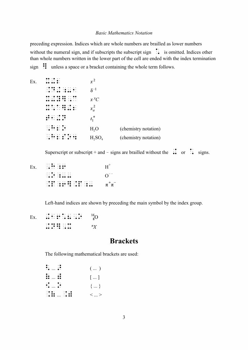
preceding expression. Indices which are whole numbers are brailled as lower numbers
without the numeral sign, and if subscripts the subscript sign * is omitted. Indices other
than whole numbers written in the lower part of the cell are ended with the index termination
sign ] unless a space or a bracket containing the whole term follows.
Ex. x+2
.d+;-1
x+y],c
x*a]+2
t1+n
2,h2o H O (chemistry notation)
2 4,h2so4 H SO (chemistry notation)
Superscript or subscript + and ! signs are brailled without the + or * signs.
Ex. ,h;6 H+
,o;-- O!!
.p;6].p;-
Left-hand indices are shown by preceding the main symbol by the index group.
Ex. +16*8,o
+n],x
Brackets
The following mathematical brackets are used:
< ... > ( ... )
( ... ) [ ... ]
[ ... o { ... }
.( ... .) < ... >
Basic Mathematics Notation
4
Operation and Relation Signs
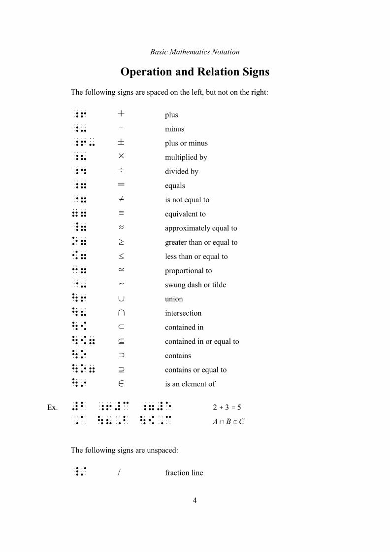
The following signs are spaced on the left, but not on the right:
;6 + plus
;- ! minus
;6- ± plus or minus
;8 × multiplied by
;4 ÷ divided by
;7 = equals
"7 � is not equal to
77 / equivalent to
_7 . approximately equal to
o7 $ greater than or equal to
[7 # less than or equal to
37 % proportional to
"- - swung dash or tilde
\6 c union
\8 1 intersection
\[ d contained in
\[7 f contained in or equal to
\o e contains
\o7 g contains or equal to
\9 0 is an element of
Ex. #b ;6#c ;7#e
,a \8,b \[,c
The following signs are unspaced:
_/ / fraction line
Basic Mathematics Notation
5
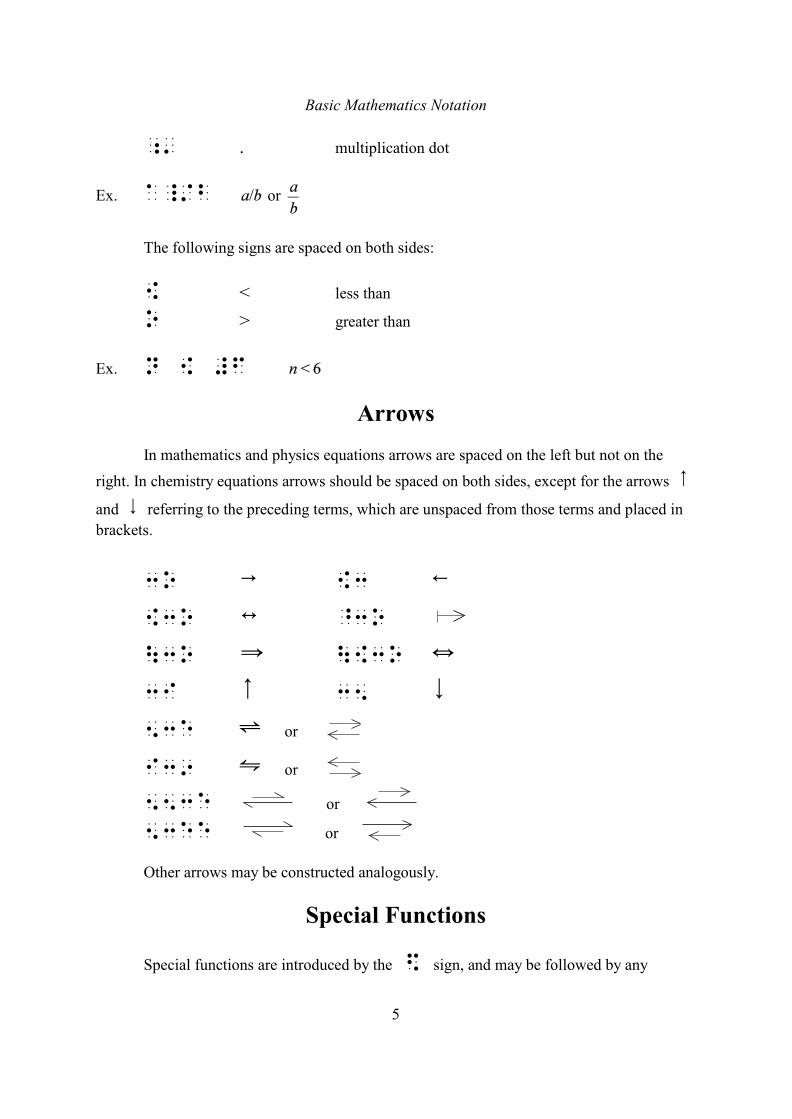
;' . multiplication dot
Ex. a_/b or
The following signs are spaced on both sides:
[ < less than
o > greater than
Ex. n [ #f
Arrows
In mathematics and physics equations arrows are spaced on the left but not on the
right. In chemistry equations arrows should be spaced on both sides, except for the arrows 8and 9 referring to the preceding terms, which are unspaced from those terms and placed in
brackets.
3o 6 [3 7[3o : ^3o
\3o Y \[3o ]3i 8 35 953e º or
i39 » or
553e or
53ee or
Other arrows may be constructed analogously.
Special Functions
Special functions are introduced by the $ sign, and may be followed by any
Basic Mathematics Notation
6
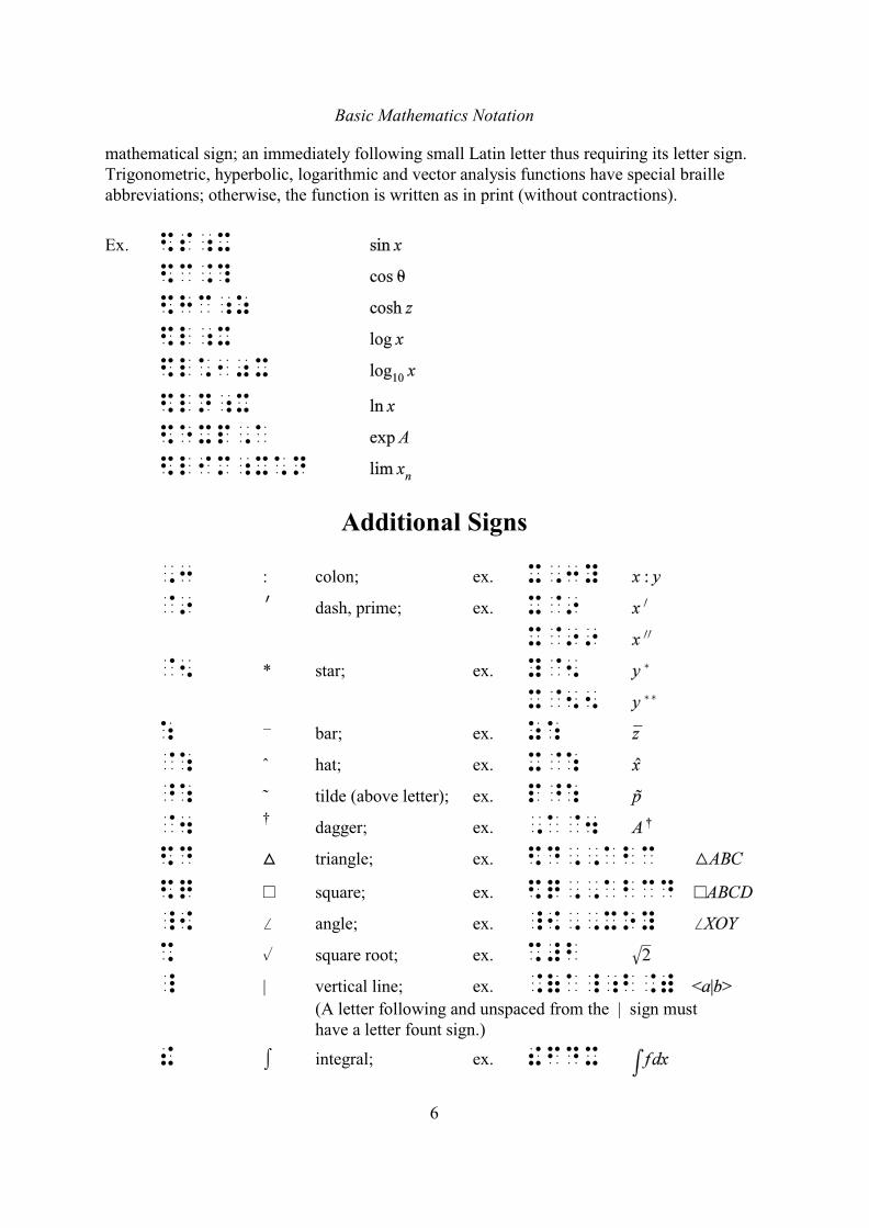
mathematical sign; an immediately following small Latin letter thus requiring its letter sign.Trigonometric, hyperbolic, logarithmic and vector analysis functions have special brailleabbreviations; otherwise, the function is written as in print (without contractions).
Ex. $s;x
$c.?
$hc;z
$l;x
$l*10x
$ln;x
$exp,a
$lim;x*n
Additional Signs
,3 : colon; ex. x,3y
@9 N dash, prime; ex. x@9
x@99
@5 * star; ex. y@5
x@55
: G bar; ex. z:
@: ˆ hat; ex. x@:
^: ˜ tilde (above letter); ex. p^:
@4 dagger; ex. ,a@4†
$d ª triangle; ex. $d,,abc
$q ~ square; ex. $q,,abcd
_{ p angle; ex. _{,,xoy
% % square root; ex. %#b
_ | vertical line; ex. .(a_;b.)
(A letter following and unspaced from the | sign musthave a letter fount sign.)
! I integral; ex. !fdx
7
2UNITS
(Tables of standard unit abbreviations are given at the end of this section forreference.)
(Note: The examples in this section have been chosen to illustrate a variety of printforms as found: this choice is not intended to indicate recommended practice.)
1 Units are placed before or after the number to which they refer, according to print. Unitsshould be spaced in braille, apart from the signs in §5 denoting units of angle and length infeet and inches, monetary unit abbreviations preceding the number, and single letter monetaryunit abbreviations or symbols following the number.
2 Unit abbreviations are generally coded using the usual conventions of literary andmathematics braille notation, e.g. as regards the use of the letter sign and capital sign. Notethat the letter sign is not required before unit abbreviations consisting of two or more lowercase letters belonging to one word, e.g. cm for centimetre, but it is required where a lowercase letter is followed by an upper case letter at the beginning of a unit abbreviation, e.g. mWfor milliwatts.
2.1 Capitals should normally be indicated, even in non-capitalized braille. However,conventional informal abbreviations such as MPH, M.P.H., MPG, etc., can be treated aslower case in non-capitalized braille.
2.2 mmHg should be coded with a dot 6 before the abbreviation Hg for mercury, unless thespecial braille code for chemistry is being used (see section 3).
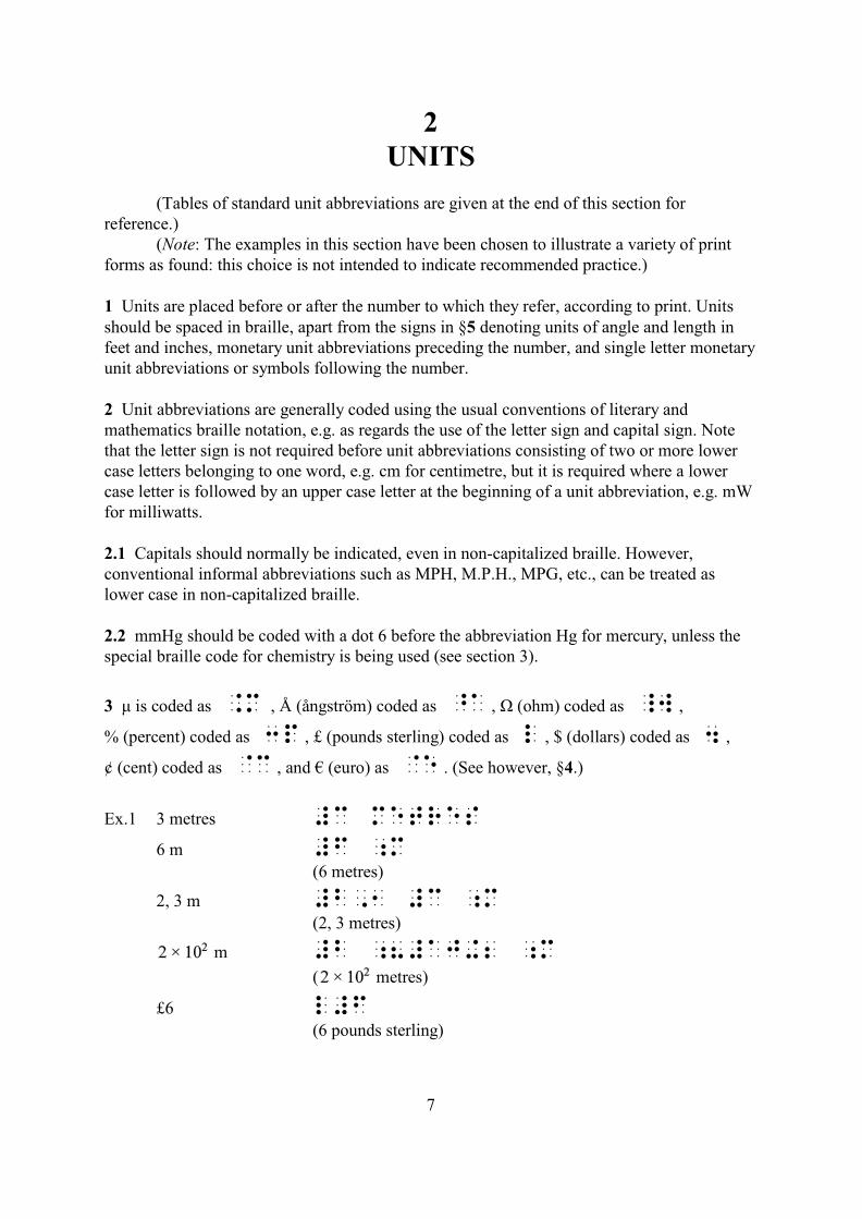
3 ì is coded as .m , Å (ångström) coded as ^a , Ù (ohm) coded as _w ,
% (percent) coded as 3p , £ (pounds sterling) coded as l , $ (dollars) coded as 4 ,
¢ (cent) coded as @c , and € (euro) as @e . (See however, §4.)
Ex.1 3 metres #c metres
6 m #f ;m(6 metres)
2, 3 m #b,1 #c ;m(2, 3 metres)
m #b ;8#aj+2 ;m
( metres)
£6 l#f(6 pounds sterling)
Units
8
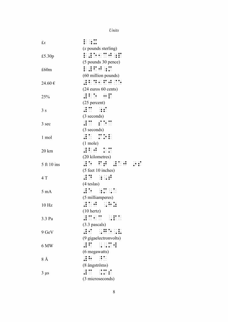
£x l;x(x pounds sterling)
£5.30p l#e1cj;p(5 pounds 30 pence)
£60m l#fj;m(60 million pounds)
24.60 € #bd1fj@e(24 euros 60 cents)
25% #be 3p(25 percent)
3 s #c ;s(3 seconds)
3 sec #c sec(3 seconds)
1 mol #a mol(1 mole)
20 km #bj km(20 kilometres)
5 ft 10 ins #e ft #aj 9s(5 feet 10 inches)
4 T #d ;,t(4 teslas)
5 mA #e ;m,a(5 milliamperes)
10 Hz #aj ,hz(10 hertz)
3.3 Pa #c1c ,pa(3.3 pascals)
9 GeV #I ,ge,v(9 gigaelectronvolts)
6 MW #f ,,mw(6 megawatts)
8 Å #h ^a(8 ångströms)
3 ìs #c .ms(3 microseconds)
Units
9
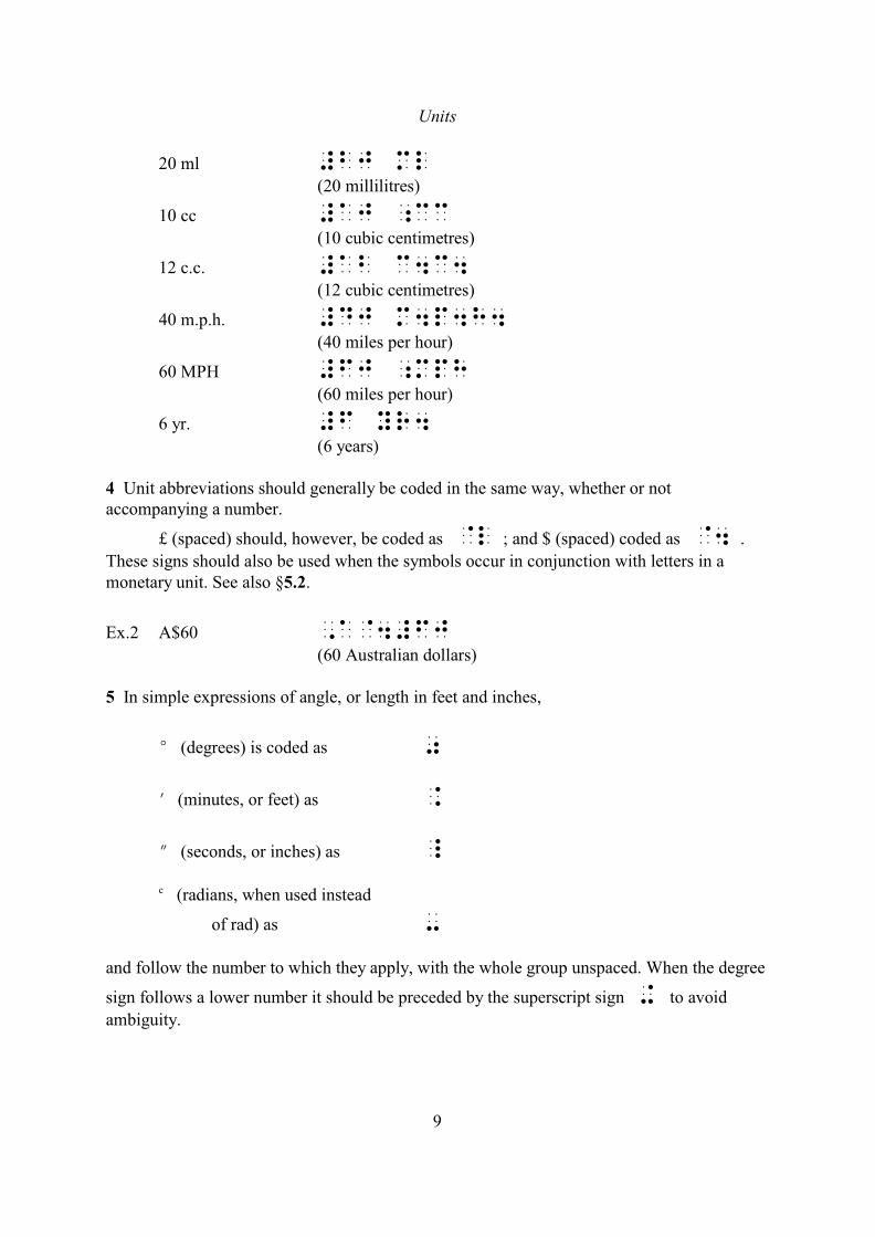
20 ml #bj ml(20 millilitres)
10 cc #aj ;cc(10 cubic centimetres)
12 c.c. #ab c4c4(12 cubic centimetres)
40 m.p.h. #dj m4p4h4(40 miles per hour)
60 MPH #fj ;mph(60 miles per hour)
6 yr. #f yr4(6 years)
4 Unit abbreviations should generally be coded in the same way, whether or notaccompanying a number.
£ (spaced) should, however, be coded as @l ; and $ (spaced) coded as @4 .
These signs should also be used when the symbols occur in conjunction with letters in amonetary unit. See also §5.2.
Ex.2 A$60 ,a@4#fj(60 Australian dollars)
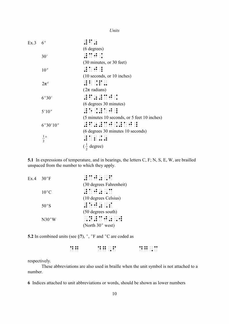
5 In simple expressions of angle, or length in feet and inches,
E (degrees) is coded as 0
N (minutes, or feet) as .
O (seconds, or inches) as _
(radians, when used insteadc
of rad) as -
and follow the number to which they apply, with the whole group unspaced. When the degree
sign follows a lower number it should be preceded by the superscript sign + to avoid
ambiguity.
Units
10
Ex.3 6E #f0(6 degrees)
30N #cj.(30 minutes, or 30 feet)
10O #aj_(10 seconds, or 10 inches)
#b.p-( radians)
6E30N #f0#cj.(6 degrees 30 minutes)
5N10O #e.#aj_(5 minutes 10 seconds, or 5 feet 10 inches)
6E30N10O #f0#cj.#aj_(6 degrees 30 minutes 10 seconds)
#a2+0
( degree)
5.1 In expressions of temperature, and in bearings, the letters C, F; N, S, E, W, are brailledunspaced from the number to which they apply.
Ex.4 30EF #cj0,f(30 degrees Fahrenheit)
10EC #aj0,c(10 degrees Celsius)
50ES #ej0,s(50 degrees south)
N30EW ,n#cj0,w(North 30E west)
5.2 In combined units (see §7), E, EF and EC are coded as
dg dg,f dg,c
respectively.These abbreviations are also used in braille when the unit symbol is not attached to a
number.
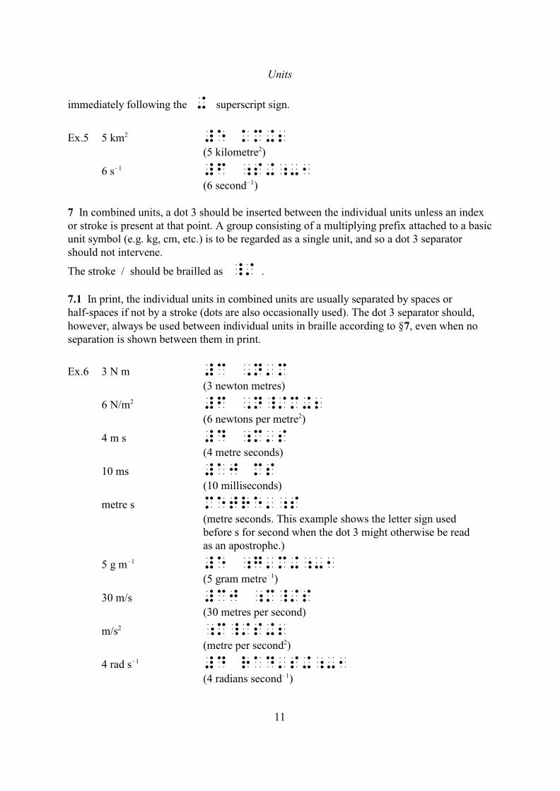
6 Indices attached to unit abbreviations or words, should be shown as lower numbers
Units
11
immediately following the + superscript sign.
Ex.5 5 km #e km+22
(5 kilometre )2
6 s #f ;s+;-1!1
(6 second )!1
7 In combined units, a dot 3 should be inserted between the individual units unless an indexor stroke is present at that point. A group consisting of a multiplying prefix attached to a basicunit symbol (e.g. kg, cm, etc.) is to be regarded as a single unit, and so a dot 3 separatorshould not intervene.
The stroke / should be brailled as _/ .
7.1 In print, the individual units in combined units are usually separated by spaces orhalf-spaces if not by a stroke (dots are also occasionally used). The dot 3 separator should,however, always be used between individual units in braille according to §7, even when noseparation is shown between them in print.
Ex.6 3 N m #c ,n'm(3 newton metres)
6 N/m #f ,n_/m+22
(6 newtons per metre )2
4 m s #d ;m's(4 metre seconds)
10 ms #aj ms(10 milliseconds)
metre s metre';s(metre seconds. This example shows the letter sign usedbefore s for second when the dot 3 might otherwise be readas an apostrophe.)
5 g m #e ;g'm+;-1!1
(5 gram metre )!1
30 m/s #cj ;m_/s(30 metres per second)
m/s ;m_/s+22
(metre per second )2
4 rad s #d rad's+;-1!1
(4 radians second )!1
Units
12
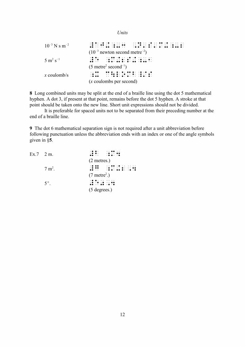
10 N s m #aj+;-3 ,n's'm+;-2!3 !2
(10 newton second metre )!3 !2
5 m s #e ;m+2s+;-12 !1
(5 metre second )2 !1
x coulomb/s ;x c\lomb_/s(x coulombs per second)
8 Long combined units may be split at the end of a braille line using the dot 5 mathematicalhyphen. A dot 3, if present at that point, remains before the dot 5 hyphen. A stroke at thatpoint should be taken onto the new line. Short unit expressions should not be divided.
It is preferable for spaced units not to be separated from their preceding number at theend of a braille line.
9 The dot 6 mathematical separation sign is not required after a unit abbreviation beforefollowing punctuation unless the abbreviation ends with an index or one of the angle symbolsgiven in §5.
Ex.7 2 m. #b ;m4(2 metres.)
7 m . #g ;m+2,42
(7 metre .)2
5E. #e0,4(5 degrees.)
Units
13
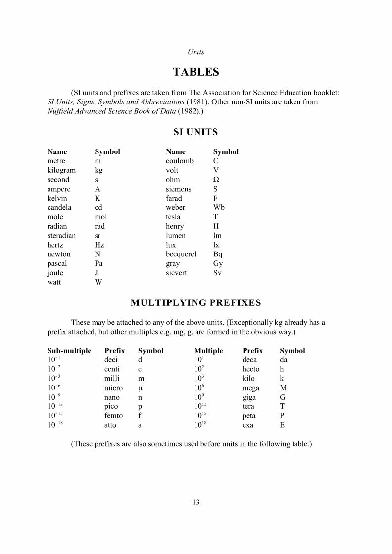
TABLES
(SI units and prefixes are taken from The Association for Science Education booklet:SI Units, Signs, Symbols and Abbreviations (1981). Other non-SI units are taken fromNuffield Advanced Science Book of Data (1982).)
SI UNITS
Name Symbol Name Symbolmetre m coulomb Ckilogram kg volt Vsecond s ohm Ùampere A siemens Skelvin K farad Fcandela cd weber Wbmole mol tesla Tradian rad henry Hsteradian sr lumen lmhertz Hz lux lxnewton N becquerel Bqpascal Pa gray Gyjoule J sievert Svwatt W
MULTIPLYING PREFIXES
These may be attached to any of the above units. (Exceptionally kg already has aprefix attached, but other multiples e.g. mg, g, are formed in the obvious way.)
Sub-multiple Prefix Symbol Multiple Prefix Symbol10 deci d 10 deca da!1 1
10 centi c 10 hecto h!2 2
10 milli m 10 kilo k!3 3
10 micro ì 10 mega M!6 6
10 nano n 10 giga G!9 9
10 pico p 10 tera T!12 12
10 femto f 10 peta P!15 15
10 atto a 10 exa E!18 18
(These prefixes are also sometimes used before units in the following table.)
Units
14
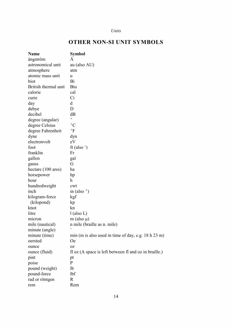
OTHER NON-SI UNIT SYMBOLS
Name Symbolångström Åastronomical unit au (also AU)atmosphere atmatomic mass unit ubiot BiBritish thermal unit Btucalorie calcurie Ciday ddebye Ddecibel dBdegree (angular) Edegree Celsius ECdegree Fahrenheit EFdyne dynelectronvolt eVfoot ft (also N)franklin Frgallon galgauss Ghectare (100 ares) hahorsepower hphour hhundredweight cwtinch in (also O)kilogram-force kgf (kilopond) kpknot knlitre l (also L)micron m (also ì)mile (nautical) n mile (braille as n. mile)minute (angle) Nminute (time) min (m is also used in time of day, e.g. 18 h 23 m)oersted Oeounce ozounce (fluid) fl oz (A space is left between fl and oz in braille.)pint ptpoise Ppound (weight) lbpound-force lbfrad or röntgen Rrem Rem

Units
15
second (angle) Ostokes Stton-force ton f (braille as tonf)tonne ttorr TorrX unit Xuyard ydyear a
16
3CHEMISTRY NOTATION
NOTE
The method of coding structural formulae given in sections 17-26 of this code isintended to be an alternative or an addition to diagrammatic representation, to be used whenconvenient. Diagrammatic representation should generally be regarded as the primarymethod. Section 17 should, however, be generally used to represent structural formulaeprinted linearly with dots indicating bonds.
The coding of structural formulae by these methods is not intended to be necessarilyunique: several of the examples given have alternative codings which may be preferred inparticular contexts.
In some work it may be found advantageous to waive the stated convention ofprefixing formulae in chemical equations by the dot 6 letter fount sign, for example, inchemistry textbooks. In such cases, however, advance notice should be given.
GENERAL NOTATION
Chemical Names
1 The use of italics for prefixes in chemical names (e.g. cyclo, iso, etc.) should bedisregarded in braille.
2 In organic chemistry, punctuation (e.g. commas or colons) between numbers in chemicalnames indicating the position of groups should be omitted, the numbers being coded as anunspaced sequence.
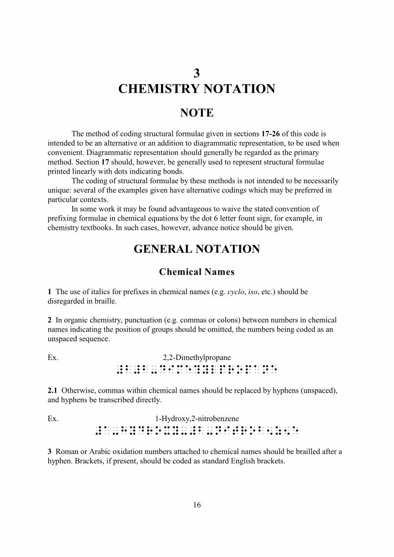
Ex. 2,2-Dimethylpropane
#b#b-dime?ylpropane
2.1 Otherwise, commas within chemical names should be replaced by hyphens (unspaced),and hyphens be transcribed directly.
Ex. 1-Hydroxy,2-nitrobenzene
#a-hydroxy-#b-nitrob5z5e
3 Roman or Arabic oxidation numbers attached to chemical names should be brailled after ahyphen. Brackets, if present, should be coded as standard English brackets.
Chemistry Notation
17
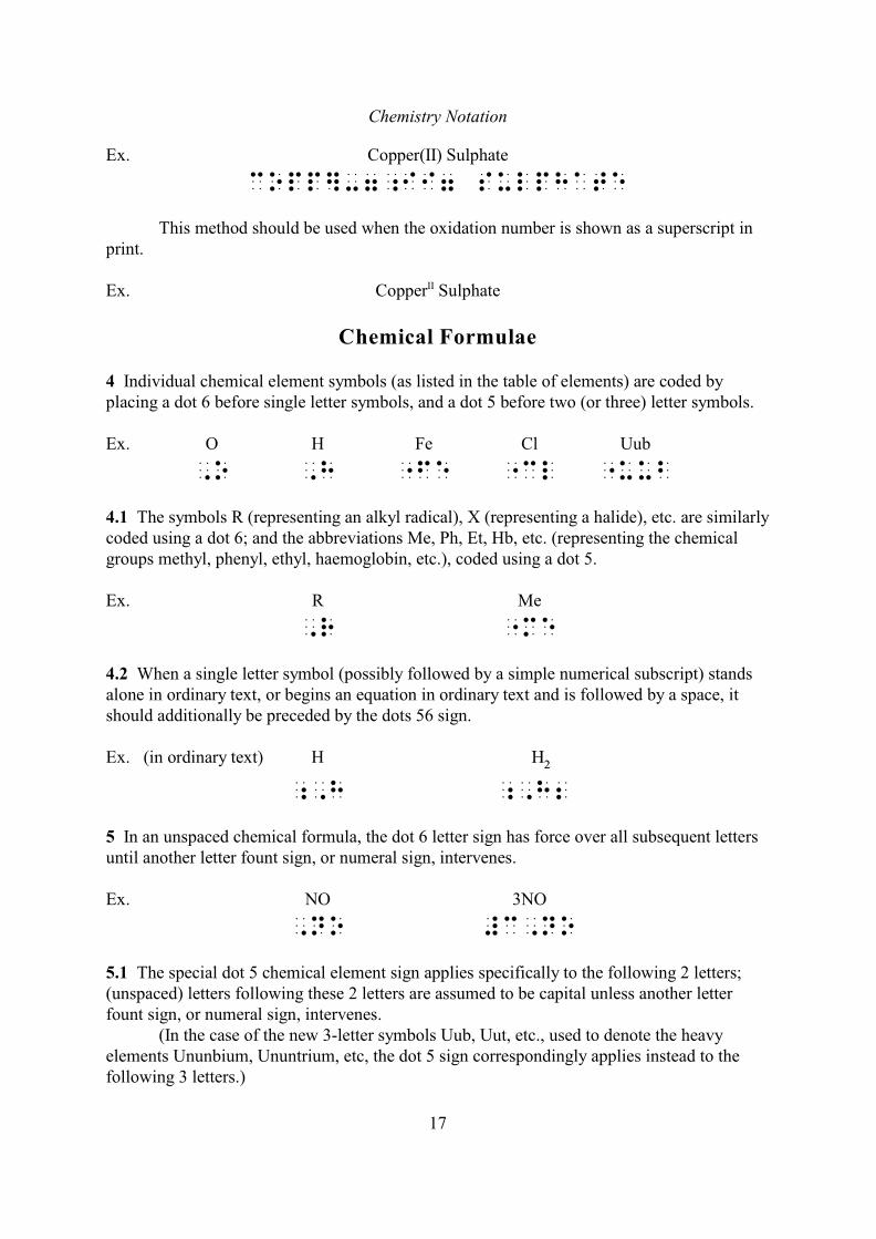
Ex. Copper(II) Sulphate
copp]-7;ii7 sulphate
This method should be used when the oxidation number is shown as a superscript inprint.
Ex. Copper SulphateII
Chemical Formulae
4 Individual chemical element symbols (as listed in the table of elements) are coded byplacing a dot 6 before single letter symbols, and a dot 5 before two (or three) letter symbols.
Ex. O H Fe Cl Uub
,O ,h "Fe "Cl "uub
4.1 The symbols R (representing an alkyl radical), X (representing a halide), etc. are similarlycoded using a dot 6; and the abbreviations Me, Ph, Et, Hb, etc. (representing the chemicalgroups methyl, phenyl, ethyl, haemoglobin, etc.), coded using a dot 5.
Ex. R Me
,R "Me
4.2 When a single letter symbol (possibly followed by a simple numerical subscript) standsalone in ordinary text, or begins an equation in ordinary text and is followed by a space, itshould additionally be preceded by the dots 56 sign.
Ex. (in ordinary text) H
;,h ;,h2
5 In an unspaced chemical formula, the dot 6 letter sign has force over all subsequent lettersuntil another letter fount sign, or numeral sign, intervenes.
Ex. NO 3NO
,NO #c,no
5.1 The special dot 5 chemical element sign applies specifically to the following 2 letters;(unspaced) letters following these 2 letters are assumed to be capital unless another letterfount sign, or numeral sign, intervenes.
(In the case of the new 3-letter symbols Uub, Uut, etc., used to denote the heavyelements Ununbium, Ununtrium, etc, the dot 5 sign correspondingly applies instead to thefollowing 3 letters.)
Chemistry Notation
18
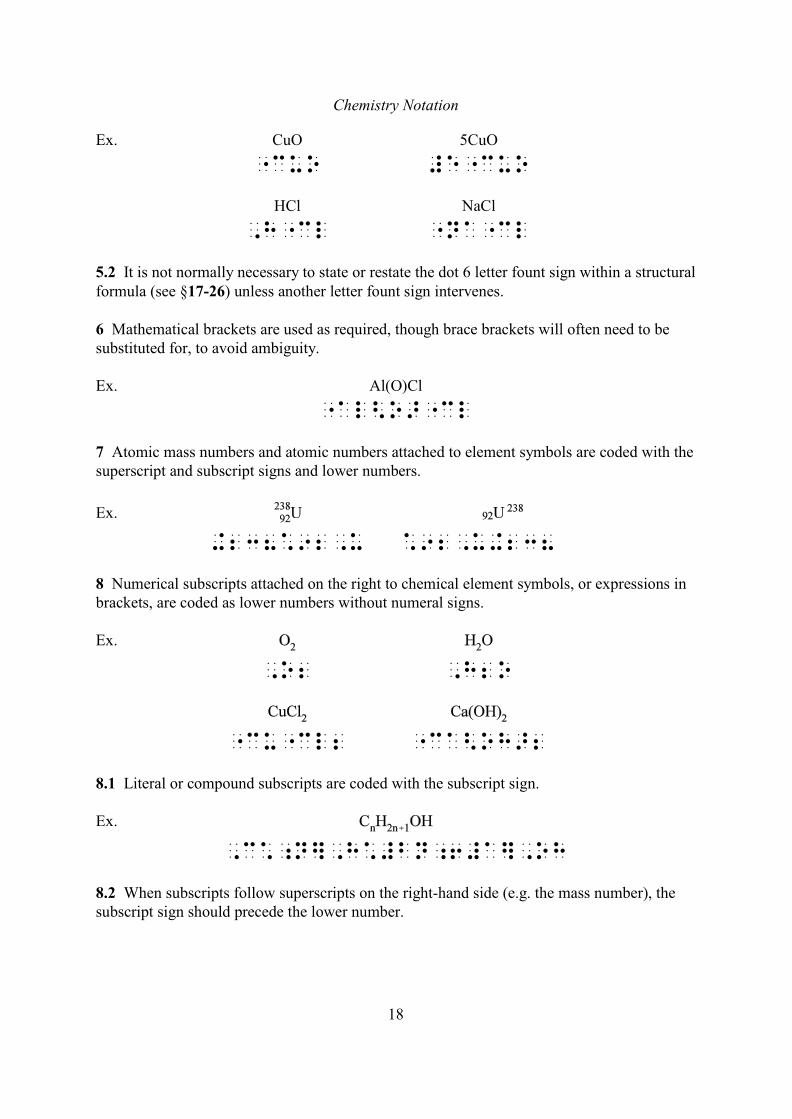
Ex. CuO 5CuO
"cuo #e"cuo
HCl NaCl
,h"cl "na"cl
5.2 It is not normally necessary to state or restate the dot 6 letter fount sign within a structuralformula (see §17-26) unless another letter fount sign intervenes.
6 Mathematical brackets are used as required, though brace brackets will often need to besubstituted for, to avoid ambiguity.
Ex. Al(O)Cl
"al<o>"cl
7 Atomic mass numbers and atomic numbers attached to element symbols are coded with thesuperscript and subscript signs and lower numbers.
Ex.
+238*92,u *92,u+238
8 Numerical subscripts attached on the right to chemical element symbols, or expressions inbrackets, are coded as lower numbers without numeral signs.
Ex.
,o2 ,h2o
"cu"cl2 "ca<oh>2
8.1 Literal or compound subscripts are coded with the subscript sign.
Ex.
,c*;n],h*#bn;6#a],oh
8.2 When subscripts follow superscripts on the right-hand side (e.g. the mass number), thesubscript sign should precede the lower number.
Chemistry Notation
19
Ex.
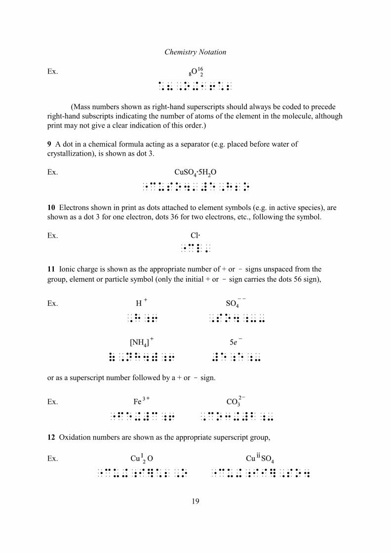
*8,o+16*2
(Mass numbers shown as right-hand superscripts should always be coded to precederight-hand subscripts indicating the number of atoms of the element in the molecule, althoughprint may not give a clear indication of this order.)
9 A dot in a chemical formula acting as a separator (e.g. placed before water ofcrystallization), is shown as dot 3.
Ex.
"cuso4'#e,h2o
10 Electrons shown in print as dots attached to element symbols (e.g. in active species), areshown as a dot 3 for one electron, dots 36 for two electrons, etc., following the symbol.
Ex.
"cl'
11 Ionic charge is shown as the appropriate number of + or signs unspaced from the
group, element or particle symbol (only the initial + or sign carries the dots 56 sign),
Ex.
,h;6 ,so4;--
(,nh4);6 #e;e;-
or as a superscript number followed by a + or sign.
Ex.
"fe+#c;6 ,co3+#b;-
12 Oxidation numbers are shown as the appropriate superscript group,
Ex.
"cu+;I]*2,o "cu+;ii],so4
Chemistry Notation
20
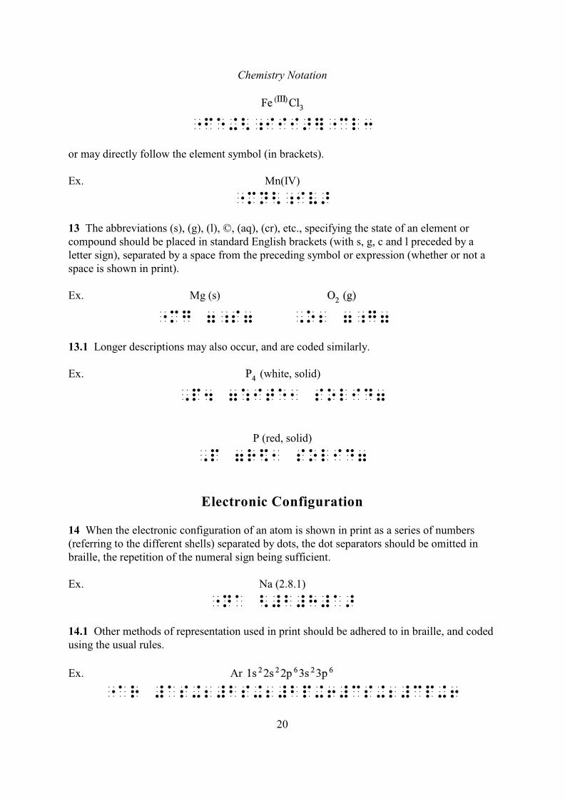
"fe+<;Iii>]"cl3
or may directly follow the element symbol (in brackets).
Ex. Mn(IV)
"mn<;iv>
13 The abbreviations (s), (g), (l), ©, (aq), (cr), etc., specifying the state of an element orcompound should be placed in standard English brackets (with s, g, c and l preceded by aletter sign), separated by a space from the preceding symbol or expression (whether or not aspace is shown in print).
Ex. Mg (s)
"mg 7;s7 ,o2 7;g7
13.1 Longer descriptions may also occur, and are coded similarly.
Ex. (white, solid)
,p4 7:ite1 solid7
P (red, solid)
,p 7r$1 solid7
Electronic Configuration
14 When the electronic configuration of an atom is shown in print as a series of numbers(referring to the different shells) separated by dots, the dot separators should be omitted inbraille, the repetition of the numeral sign being sufficient.
Ex. Na (2.8.1)
"na <#b#h#a>
14.1 Other methods of representation used in print should be adhered to in braille, and codedusing the usual rules.
Ex. Ar
"ar #as+2#bs+2#bp+6#cs+2#cp+6
Chemistry Notation
21
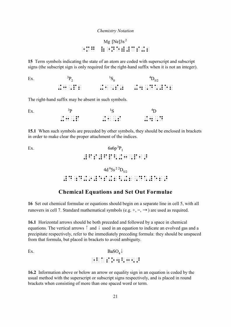
Mg
"mg ("ne)#cs+2
15 Term symbols indicating the state of an atom are coded with superscript and subscriptsigns (the subscript sign is only required for the right-hand suffix when it is not an integer).
Ex.
+3,p2 +1,s0 +4,d*#e2
The right-hand suffix may be absent in such symbols.
Ex.
+3,p +1,s +4,d
15.1 When such symbols are preceded by other symbols, they should be enclosed in bracketsin order to make clear the proper attachment of the indices.
Ex.
#fs#fp<+3,p1>
#d;d+9#es+2<+2,d*#e2>
Chemical Equations and Set Out Formulae
16 Set out chemical formulae or equations should begin on a separate line in cell 5, with all
6runovers in cell 7. Standard mathematical symbols (e.g. +, =, ) are used as required.
16.1 Horizontal arrows should be both preceded and followed by a space in chemical
equations. The vertical arrows 8 and 9 used in an equation to indicate an evolved gas and a
precipitate respectively, refer to the immediately preceding formula: they should be unspacedfrom that formula, but placed in brackets to avoid ambiguity.
Ex.
"baso4<35>
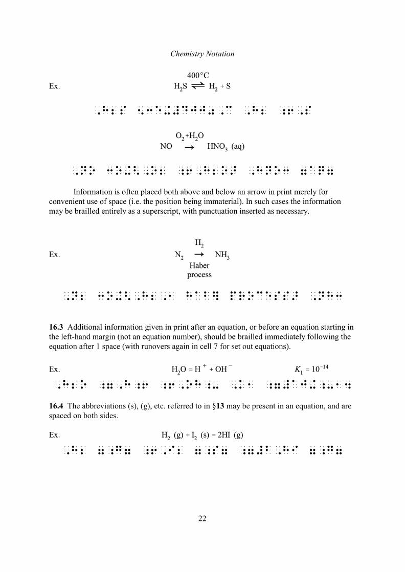
16.2 Information above or below an arrow or equality sign in an equation is coded by theusual method with the superscript or subscript signs respectively, and is placed in roundbrackets when consisting of more than one spaced word or term.
Chemistry Notation
22
Ex.
,h2s 53e+#djj0,c ,h2 ;6,s
,no 3o+<,o2 ;6,h2o> ,hno3 7aq7
Information is often placed both above and below an arrow in print merely forconvenient use of space (i.e. the position being immaterial). In such cases the informationmay be brailled entirely as a superscript, with punctuation inserted as necessary.
Ex.
,n2 3o+<,h2,1 hab] process> ,nh3
16.3 Additional information given in print after an equation, or before an equation starting inthe left-hand margin (not an equation number), should be brailled immediately following theequation after 1 space (with runovers again in cell 7 for set out equations).
Ex.
,h2o ;7,h;6 ;6,oh;- ,k1 ;7#aj+;-14
16.4 The abbreviations (s), (g), etc. referred to in §13 may be present in an equation, and arespaced on both sides.
Ex.
,h2 7;g7 ;6,i2 7;s7 ;7#b,hi 7;g7
Chemistry Notation
23
STRUCTURAL FORMULAE
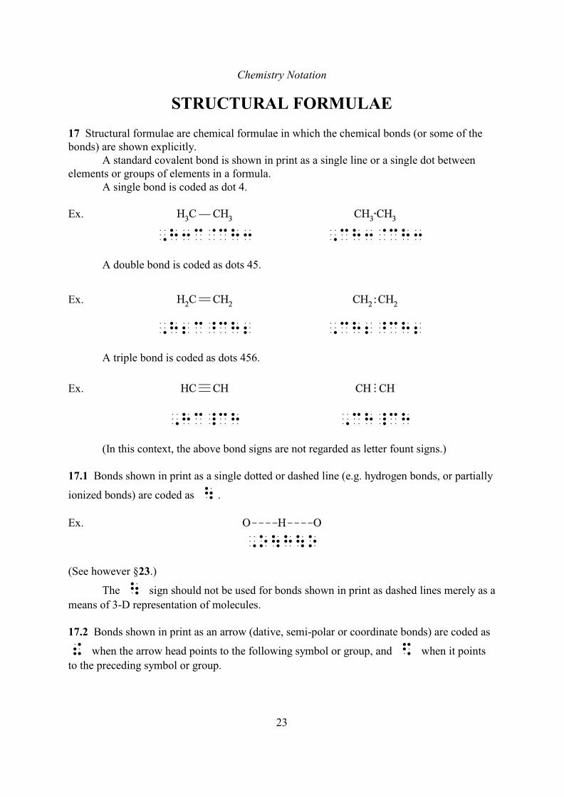
17 Structural formulae are chemical formulae in which the chemical bonds (or some of thebonds) are shown explicitly.
A standard covalent bond is shown in print as a single line or a single dot betweenelements or groups of elements in a formula.
A single bond is coded as dot 4.
Ex.
,h3c@ch3 ,ch3@ch3
A double bond is coded as dots 45.
Ex.
,h2c^ch2 ,ch2^ch2
A triple bond is coded as dots 456.
Ex.
,hc_ch ,ch_ch
(In this context, the above bond signs are not regarded as letter fount signs.)
17.1 Bonds shown in print as a single dotted or dashed line (e.g. hydrogen bonds, or partially
ionized bonds) are coded as \ .
Ex.
,o\h\o
(See however §23.)
The \ sign should not be used for bonds shown in print as dashed lines merely as a
means of 3-D representation of molecules.
17.2 Bonds shown in print as an arrow (dative, semi-polar or coordinate bonds) are coded as
! when the arrow head points to the following symbol or group, and $ when it points
to the preceding symbol or group.
Chemistry Notation
24
Ex.
,o^o!o ,o$o^o
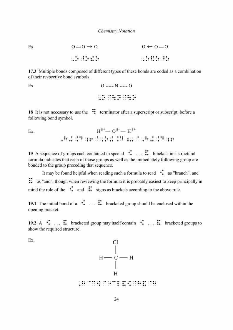
17.3 Multiple bonds composed of different types of these bonds are coded as a combinationof their respective bond symbols.
Ex.
,o@\n@\o
18 It is not necessary to use the ] terminator after a superscript or subscript, before a
following bond symbol.
Ex.
,h+.d;6@,o+.d;-@,h+.d;6
19 A sequence of groups each contained in special [ . . . & brackets in a structural
formula indicates that each of those groups as well as the immediately following group arebonded to the group preceding that sequence.
It may be found helpful when reading such a formula to read [ as "branch", and
& as "and", though when reviewing the formula it is probably easiest to keep principally in
mind the role of the [ and & signs as brackets according to the above rule.
19.1 The initial bond of a [ . . . & bracketed group should be enclosed within the
opening bracket.
19.2 A [ . . . & bracketed group may itself contain [ . . . & bracketed groups to
show the required structure.
Ex.
,h@c[@"cl&[@h&@h
Chemistry Notation
25
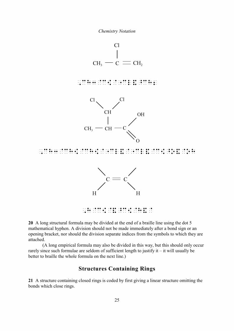
,ch3@c[@"cl&^ch2
,ch3@ch[@ch[@"cl&@"cl&@c[^o&@oh
,h@c[@&^c[@h&@
20 A long structural formula may be divided at the end of a braille line using the dot 5mathematical hyphen. A division should not be made immediately after a bond sign or anopening bracket, nor should the division separate indices from the symbols to which they areattached.
(A long empirical formula may also be divided in this way, but this should only occurrarely since such formulae are seldom of sufficient length to justify it – it will usually bebetter to braille the whole formula on the next line.)
Structures Containing Rings
21 A structure containing closed rings is coded by first giving a linear structure omitting thebonds which close rings.
Chemistry Notation
26
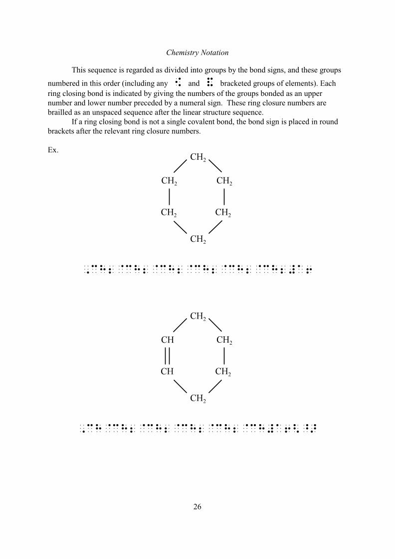
This sequence is regarded as divided into groups by the bond signs, and these groups
numbered in this order (including any [ and & bracketed groups of elements). Each
ring closing bond is indicated by giving the numbers of the groups bonded as an uppernumber and lower number preceded by a numeral sign. These ring closure numbers arebrailled as an unspaced sequence after the linear structure sequence.
If a ring closing bond is not a single covalent bond, the bond sign is placed in roundbrackets after the relevant ring closure numbers.
Ex.
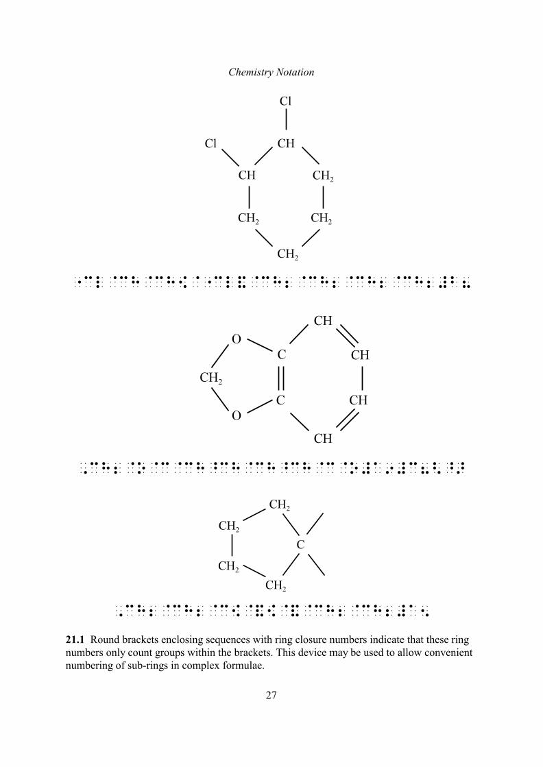
,ch2@ch2@ch2@ch2@ch2@ch2#a6
,ch@ch2@ch2@ch2@ch2@ch#a6<^>
Chemistry Notation
27
"cl@ch@ch[@"cl&@ch2@ch2@ch2@ch2#b8
,ch2@o@c@ch^ch@ch^ch@c@o#a9#c8<^>
,ch2@ch2@c[@&[@&@ch2@ch2#a5
21.1 Round brackets enclosing sequences with ring closure numbers indicate that these ringnumbers only count groups within the brackets. This device may be used to allow convenientnumbering of sub-rings in complex formulae.
Chemistry Notation
28
Ex.
,ch3@ch2@ch2@ch2<@ch@ch2@ch2@ch2"
@ch2@ch2#a6>
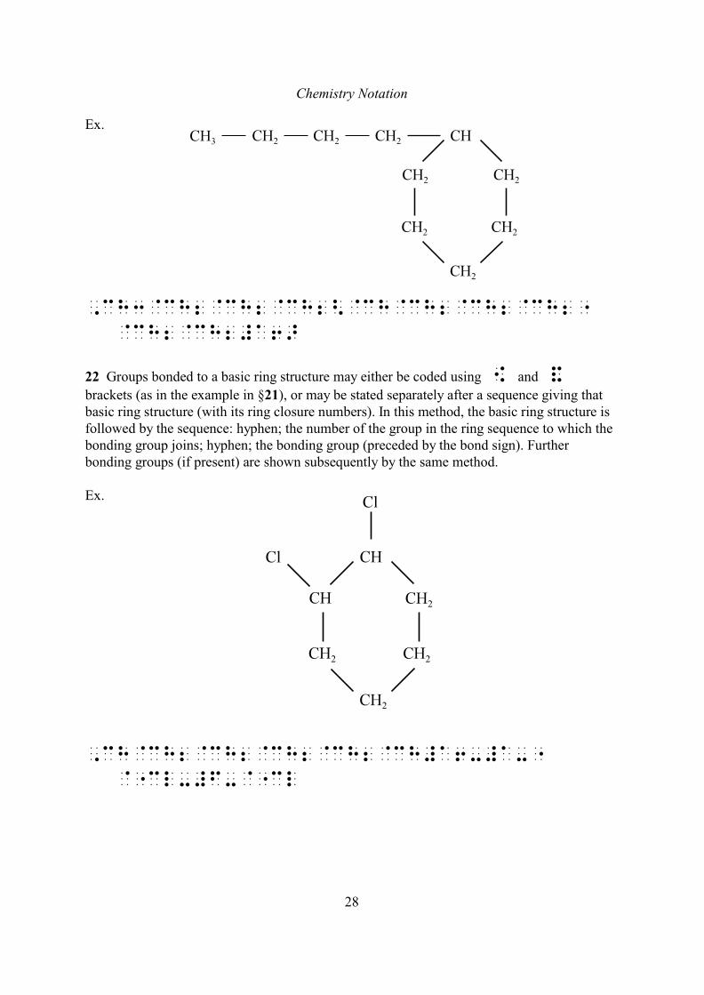
22 Groups bonded to a basic ring structure may either be coded using [ and &
brackets (as in the example in §21), or may be stated separately after a sequence giving thatbasic ring structure (with its ring closure numbers). In this method, the basic ring structure isfollowed by the sequence: hyphen; the number of the group in the ring sequence to which thebonding group joins; hyphen; the bonding group (preceded by the bond sign). Furtherbonding groups (if present) are shown subsequently by the same method.
Ex.
,ch@ch2@ch2@ch2@ch2@ch#a6-#a-"
@"cl-#f-@"cl
Chemistry Notation
29
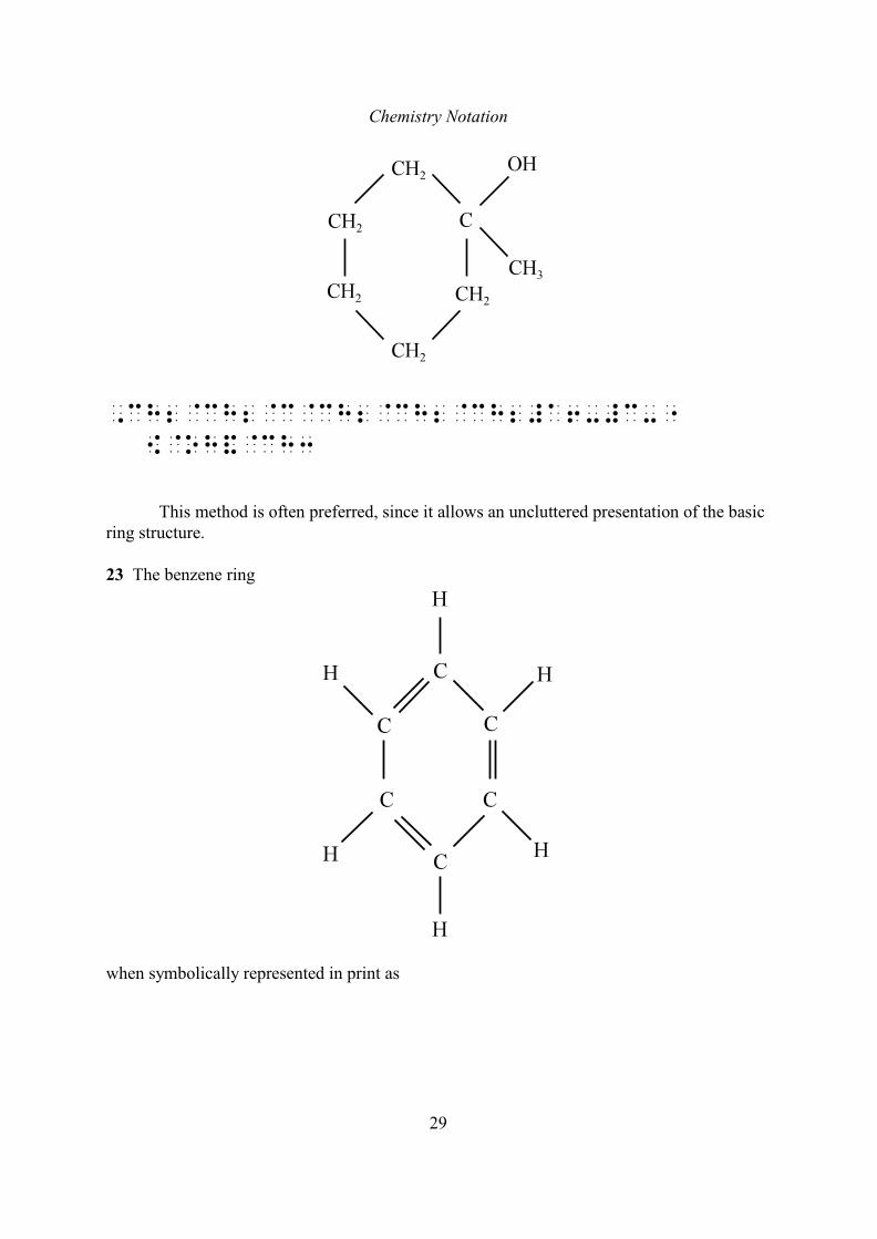
,ch2@ch2@c@ch2@ch2@ch2#a6-#c-"
[@oh&@ch3
This method is often preferred, since it allows an uncluttered presentation of the basicring structure.
23 The benzene ring
when symbolically represented in print as
Chemistry Notation
30
or
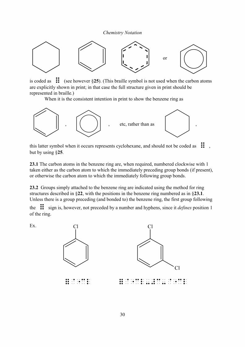
is coded as = (see however §25). (This braille symbol is not used when the carbon atoms
are explicitly shown in print; in that case the full structure given in print should berepresented in braille.)
When it is the consistent intention in print to show the benzene ring as
, , etc, rather than as ,
this latter symbol when it occurs represents cyclohexane, and should not be coded as = ,
but by using §25.
23.1 The carbon atoms in the benzene ring are, when required, numbered clockwise with 1taken either as the carbon atom to which the immediately preceding group bonds (if present),or otherwise the carbon atom to which the immediately following group bonds.
23.2 Groups simply attached to the benzene ring are indicated using the method for ringstructures described in §22, with the positions in the benzene ring numbered as in §23.1.Unless there is a group preceding (and bonded to) the benzene ring, the first group following
the = sign is, however, not preceded by a number and hyphens, since it defines position 1
of the ring.
Ex.
=@"cl =@"cl-#c-@"cl
Chemistry Notation
31
=@"cl-#c-@=
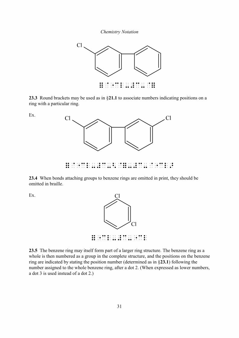
23.3 Round brackets may be used as in §21.1 to associate numbers indicating positions on aring with a particular ring.
Ex.
=@"cl-#c-<@=-#c-@"cl>
23.4 When bonds attaching groups to benzene rings are omitted in print, they should beomitted in braille.
Ex.
="cl-#c-"cl
23.5 The benzene ring may itself form part of a larger ring structure. The benzene ring as awhole is then numbered as a group in the complete structure, and the positions on the benzenering are indicated by stating the position number (determined as in §23.1) following thenumber assigned to the whole benzene ring, after a dot 2. (When expressed as lower numbers,a dot 3 is used instead of a dot 2.)
Chemistry Notation
32
Ex.
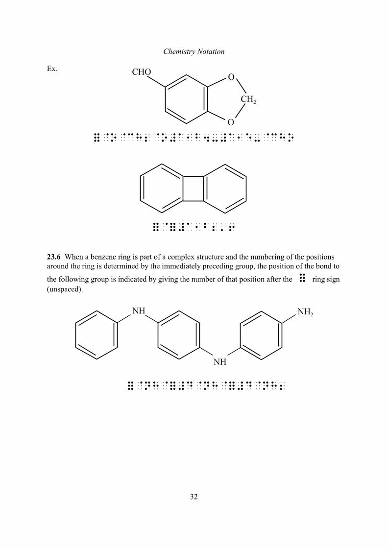
=@o@ch2@o#a1b4-#a1e-@cho
=@=#a1b2'6
23.6 When a benzene ring is part of a complex structure and the numbering of the positionsaround the ring is determined by the immediately preceding group, the position of the bond to
the following group is indicated by giving the number of that position after the = ring sign
(unspaced).
=@nh@=#d@nh@=#d@nh2

Chemistry Notation
33
Fused Benzene Rings
24 Polycyclic ring structures such as
naphthalene , phenanthrene
etc., are coded as a sequence of = signs with pairs of numbers between successive =
signs to indicate the relative position of the respective rings.
24.1 Carbon atoms within each component benzene ring are numbered clockwise (carbonatoms common to more than one ring are thus numbered more than once).
24.2 The numbers between two successive = signs in a sequence state the numbers of the
carbon atoms (as members of the first ring) which are shared with the second ring. Thenumbering within that second ring is then determined by counting the first stated of theshared carbon atoms as 1 in the second ring (the rest being numbered clockwise).
24.3 When the first = sign in such a sequence is not preceded by another group, the
numbering in the first two rings is determined by the rule that the shared carbon atoms arenumbered 1 and 2 in the first ring, and that numbered 1 in the first ring is numbered 1 in thesecond ring. In this case it is unnecessary to state the attachment position numbers 1, 2
between these = signs.
Ex.
== ==#c#d=
Chemistry Notation
34
==#d#e= ==#e#f=#d#e=
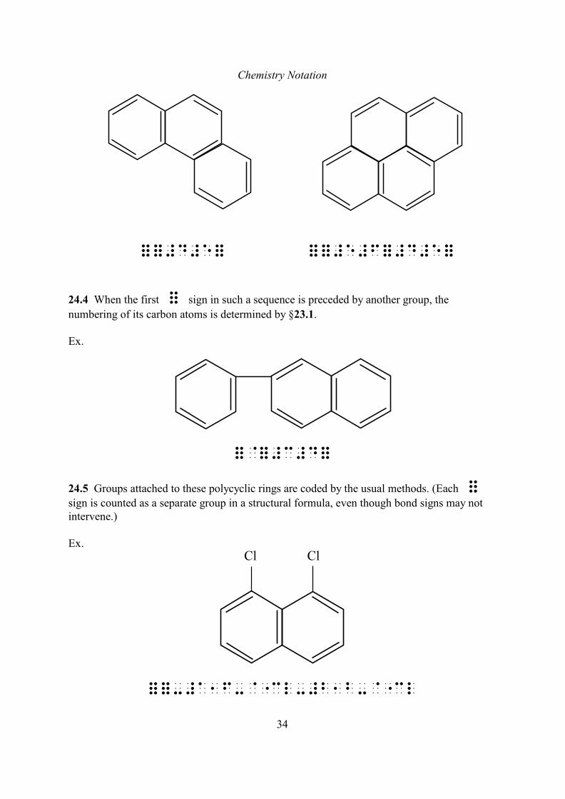
24.4 When the first = sign in such a sequence is preceded by another group, the
numbering of its carbon atoms is determined by §23.1.
Ex.
=@=#c#d=
24.5 Groups attached to these polycyclic rings are coded by the usual methods. (Each =
sign is counted as a separate group in a structural formula, even though bond signs may notintervene.)
Ex.
==-#a1f-@"cl-#b1b-@"cl
Chemistry Notation
35
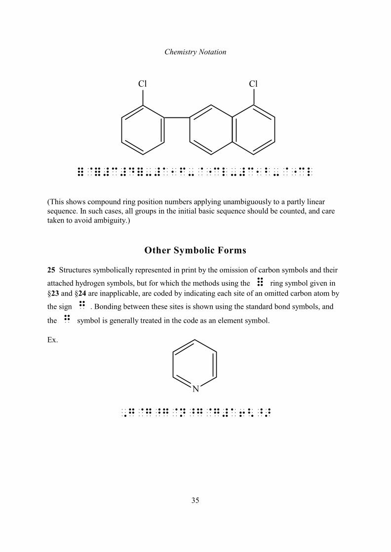
=@=#c#d=-#a1f-@"cl-#c1b-@"cl
(This shows compound ring position numbers applying unambiguously to a partly linearsequence. In such cases, all groups in the initial basic sequence should be counted, and caretaken to avoid ambiguity.)
Other Symbolic Forms
25 Structures symbolically represented in print by the omission of carbon symbols and their
attached hydrogen symbols, but for which the methods using the = ring symbol given in
§23 and §24 are inapplicable, are coded by indicating each site of an omitted carbon atom by
the sign g . Bonding between these sites is shown using the standard bond symbols, and
the g symbol is generally treated in the code as an element symbol.
Ex.
,g@g^g@n^g@g#a6<^>
Chemistry Notation
36
,g@g^g@n^g@g#a6<^>-#b-"cl
,g^g@g@g@g@g#a6-#c-[@&@ch3-#f-"
[@&@ch3
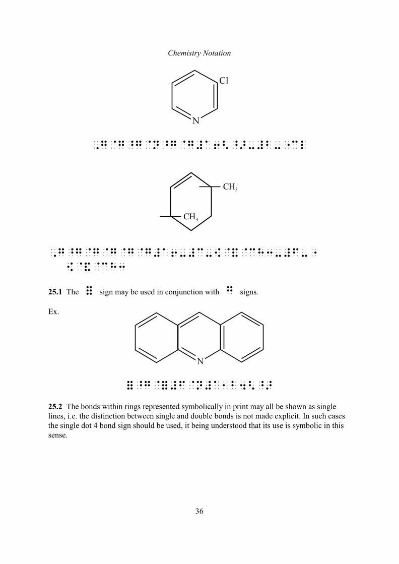
25.1 The = sign may be used in conjunction with g signs.
Ex.
=^g@=#f@n#a1b4<^>
25.2 The bonds within rings represented symbolically in print may all be shown as singlelines, i.e. the distinction between single and double bonds is not made explicit. In such casesthe single dot 4 bond sign should be used, it being understood that its use is symbolic in thissense.
Chemistry Notation
37
Ex.
,g@g@g@n@g@g#a6
Isomerism
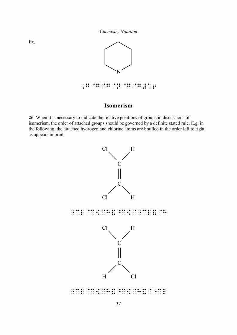
26 When it is necessary to indicate the relative positions of groups in discussions ofisomerism, the order of attached groups should be governed by a definite stated rule. E.g. inthe following, the attached hydrogen and chlorine atoms are brailled in the order left to rightas appears in print:
"cl@c[@h&^c[@"cl&@h
"cl@c[@h&^c[@h&@"cl
Chemistry Notation
38
Diagrams are, however, especially recommended to represent such information.
ADDITIONAL NOTATION
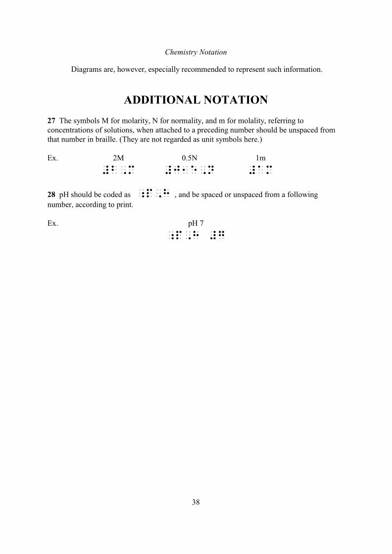
27 The symbols M for molarity, N for normality, and m for molality, referring toconcentrations of solutions, when attached to a preceding number should be unspaced fromthat number in braille. (They are not regarded as unit symbols here.)
Ex. 2M 0.5N 1m
#b,m #j1e,n #am
28 pH should be coded as ;p,h , and be spaced or unspaced from a following
number, according to print.
Ex. pH 7
;p,h #g

Chemistry Notation
39
TABLE OF ELEMENTS
Each element is placed in alphabetical order of its symbol and is followed by its atomicnumber.
Ac actinium, 89 Ge germanium, 32 Pr praseodymium,59Ag silver, 47 H hydrogen, 1 Pt platinum, 78Al aluminium, 13 He helium, 2 Pu plutonium, 94Am americium, 95 Hf hafnium, 72 Ra radium, 88Ar argon, 18 Hg mercury, 80 Rb rubidium, 37As arsenic, 33 Ho holmium, 67 Re rhenium, 75At astatine, 85 I iodine, 53 Rh rhodium, 45Au gold, 79 In indium, 49 Rn radon, 86B boron, 5 Ir iridium, 77 Ru ruthenium, 44Ba barium, 56 K potassium, 19 S sulphur, 16Be beryllium, 4 Kr krypton, 36 Sb antimony, 51Bi bismuth, 83 La lanthanum, 57 Sc scandium, 21Bk berkelium, 97 Li lithium, 3 Se selenium, 34Br bromine, 35 Lr lawrencium, 103 Si silicon, 14C carbon, 6 Lu lutetium, 71 Sm samarium, 62Ca calcium, 20 Md mendelevium, 101 Sn tin, 50Cd cadmium, 48 Mg magnesium, 12 Sr strontium, 38Ce cerium, 58 Mn manganese, 25 Ta tantalum, 73Cf californium, 98 Mo molybdenum, 42 Tb terbium, 65Cl chlorine, 17 N nitrogen, 7 Tc technetium, 43Cm curium, 96 Na sodium, 11 Te tellurium, 52Co cobalt, 27 Nb niobium, 41 Th thorium, 90Cr chromium, 24 Nd neodymium, 60 Ti titanium, 22Cs caesium, 55 Ne neon, 10 Tl thallium, 81Cu copper, 29 Ni nickel, 28 Tm thulium, 69Dy dysprosium, 66 No nobelium, 102 U uranium, 92Er erbium, 68 Np neptunium, 93 V vanadium, 23Es einsteinium, 99 O oxygen, 8 W tungsten, 74Eu europium, 63 Os osmium, 76 Xe xenon, 54F fluorine, 9 P phosphorus, 15 Y yttrium, 39Fe iron, 26 Pa protactinium, 91 Yb ytterbium, 70Fm fermium, 100 Pb lead, 82 Zn zinc, 30Fr francium, 87 Pd palladium, 46 Zr zirconium, 40Ga gallium, 31 Pm promethium, 61Gd gadolinium, 64 Po polonium, 84
40
4ELECTRONIC AND LOGIC CIRCUIT
DIAGRAMS
INTRODUCTION
Two basic methods for transcribing electronic and logic circuits are described below:
1. Diagrammatic representation.2. Braille descriptive representation.
Diagrammatic representation is the primary method used in general transcriptionwork, although the particular advantages of the braille descriptive method (e.g. in compactlytranscribing complex diagrams with few layout problems) will also merit its use in suchwork.
The different forms of diagrammatic representation enable the circuit (and anyaccompanying diagrammatic annotation) to be drawn directly; or to be drawn with theminimum of diagrammatic symbolism if preferred; or to be drawn entirely in braille.
The braille descriptive representation is a powerful method by which the connectionsin the circuit are expressed sequentially rather than graphically, and may be used otherwise asrequired.
The methods of diagrammatic representation (except the direct representation) and thebraille descriptive method each use the component and connection abbreviations given inTables A and B. Table C, giving electronic component and logic symbols, is to be used forthe identification of symbols and connections.
Other systems of representing circuits do exist and are in use, but these are notdescribed here since they generally require specialist knowledge and involve interpretation ofcircuits in order to be used effectively, which was felt to be out of place in this general usecode.
1. DIAGRAMMATIC REPRESENTATION
In any of the forms of diagrammatic representation described below, one is liable toencounter space problems. It may be found helpful to remove some of the labelling from thediagram by using a key, or it may be necessary to reproduce the diagram in sections. Whenthe latter device is used, the method should be explained beforehand, and the connectionsbetween the sections clearly indicated.
(I) Direct Representation
In this form of representation the diagram is reproduced in tactile form as it appears inprint. The labelling is in braille, and is generally coded according to the usual mathematics
Electronic and Logic Circuits
41
code conventions. In particular, capital letters will normally require dot 6 letter fount signs,though component type labels (e.g. for transistors) can be treated less formally according toSEB. Block symbols (such as logic gates) are generally more satisfactorily represented asraised shapes rather than in outline.
(ii) Diagrammatic Representation
with Components given in Braille
[Refer to examples 1 and 2.]
In this method, the diagram is represented as in (I) above, but with componentsindicated by the standard braille abbreviations given in Table A, rather than by their graphicsymbols. Reference may be made to Table C to identify components. (See the remarks in theBraille Descriptive Representation section below for guidance on giving abbreviations forblock components such as integrated circuits etc. Refer to the Logic Symbols section forguidance on simple logic symbol identifiers.) If a print label derives from the standard brailleabbreviation, then this may be used to identify the component. Otherwise the standard brailleabbreviation should be used, with the print label explained in a note or key. Components notlisted in Table A may either be denoted by abbreviations devised for the purpose (which mustbe explained) or be drawn out directly. Components with many connections (such asintegrated circuits or complex logic symbols) are also more satisfactorily representedgraphically.
Special connections are indicated, where appropriate, by the terminal abbreviationsgiven in Table B, placed adjacent to the leads entering the component. (This will not benecessary where such connections are indicated by the component being drawn out directly.)Special connections not listed in Table B may be indicated by abbreviations devised for thepurpose, and should be explained in a note or key. Care should be taken to avoid confusionwith the standard listed braille abbreviations in such cases. For logic gates (e.g. AND, OR,etc) it will not normally be necessary to label both the inputs and outputs; by simply labellingthe outputs it will be clear that the other connections are inputs. This will also apply in othersuch cases. Print labelling is reproduced (when there is room) directly.
Standard braille abbreviations used as identifiers according to this method and listedin Tables A and B (or those derived from them), and abbreviations devised and usedanalogously, will not require letter fount signs in the diagram. Such abbreviations should,however, be regarded as being capital, and be indicated as such if necessary elsewhere in thismethod (e.g. in explanatory notes), even if the abbreviation contains a braille contraction.Ordinary print labelling should be brailled as normal in the diagram, i.e. with letter and/orcapital signs.
(iii) Braille Diagrammatic Representation
[Refer to examples 3, 4, 5, 6, 7 and 8.]
In this method the circuit diagram is represented entirely in braille: the components
Electronic and Logic Circuits
42
and special connections are indicated by abbreviations as in (ii) above; the connecting linesare indicated by braille cells used graphically.
Vertical lines are indicated by _ cells aligned vertically, and horizontal lines by
lines of 3 cells. Corners, cross lines and T-junctions are represented by the appropriate
cells, used graphically, to connect up the vertical and horizontal lines. It may be necessary tomodify the arrangement of parts of the diagram in order to avoid diagonal lines which are notrepresented satisfactorily in braille. Solid spots indicating junctions can normally be omittedfor T-junctions, but should be shown for cross lines by a full cell at that junction in braille.Cross lines not forming a junction may be shown in print by the graphical device of one wire'bridging' over the other; this need not be represented in braille – the simple cross linesrepresentation should be used.
Components interrupting horizontal lines should be spaced in that line by one cellbefore and after. Abbreviations indicating special connections to that component are brailledon that same line, and are placed unspaced from the connecting lead lines (the componentabbreviation remaining spaced).
Components interrupting vertical lines should be unspaced in that line. Abbreviationsindicating special connections to that component are aligned in that same vertical line and areplaced (unspaced) between the component abbreviation and the appropriate connecting leadlines. A two-terminal component abbreviation interrupting a vertical line which has just oneadjacent special connection abbreviation should be preceded by a dot 5 in order to distinguishit from the connection abbreviation. (This device will not be necessary when the componenthas connection abbreviations both above and below it – the component abbreviation is clearlythe middle one.)
When a component has several connections on the same side with horizontal leads,they may be placed one above the other, but only the first will be on the same line as thecomponent identifier. [See examples 5 and 7.] The connection lines should be produced sothat their ends are aligned vertically (including any connection abbreviations). Componentswith several vertical leads are treated analogously, although in this case it may be possible fortwo or more vertical connections on the same side to be placed against a component identifierif the latter consists of several cells. When using this method one should be careful to spacecomponents adequately in order that the intended attachment of 'stray end' connections beclear. For greater clarity, a block component can be shown with its outline represented inbraille. This will avoid 'stray end' connections (since all the connections will meet the blockoutline as in print), but will require extra space. [See examples 6 and 8.] Rows and columnsof full cells should be used to represent the outline, to distinguish it from connecting leadswhich are represented as single dot lines. It will not be practicable to represent the specialshapes of logic gates etc., so identifying abbreviations will still be required. (It will notnormally be necessary, however, to specially indicate the output (or inputs) of such gates,since the position of the connections on the block outline should make this clear.) Thismethod will also enable complex logic symbols to be represented, the full cells being used torepresent both the outline as well as the internal sub-blocks of the symbol.
Electronic and Logic Circuits
43
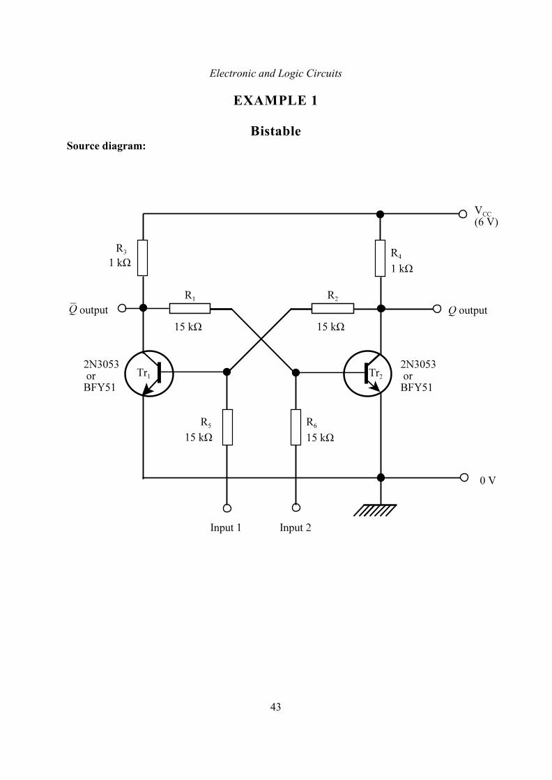
EXAMPLE 1
BistableSource diagram:
Electronic and Logic Circuits
44
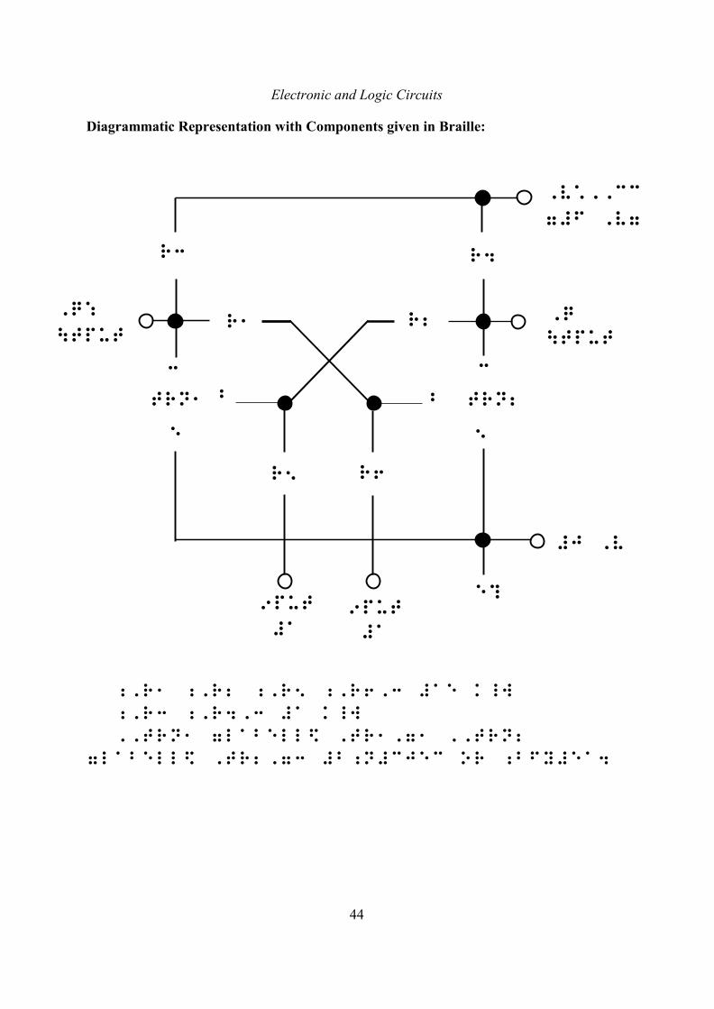
Diagrammatic Representation with Components given in Braille:
;,r1 ;,r2 ;,r5 ;,r6,3 #ae k_w
;,r3 ;,r4,3 #a k_w
,,trn1 7labell$ ,tr1,71 ,,trn2
7labell$ ,tr2,73 #b;n#cjec or ;bfy#ea4
Electronic and Logic Circuits
45
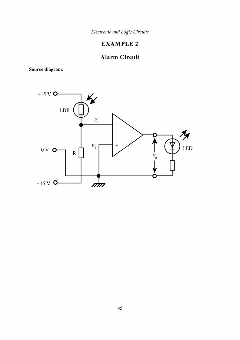
EXAMPLE 2
Alarm Circuit
Source diagram:
Electronic and Logic Circuits
46
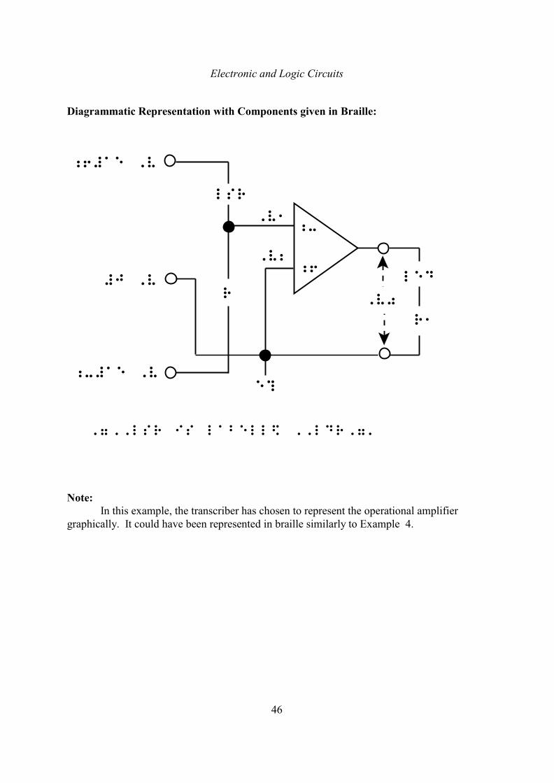
Diagrammatic Representation with Components given in Braille:
,7,,lsr is labell$ ,,ldr,7'
Note:In this example, the transcriber has chosen to represent the operational amplifier
graphically. It could have been represented in braille similarly to Example 4.
Electronic and Logic Circuits
47
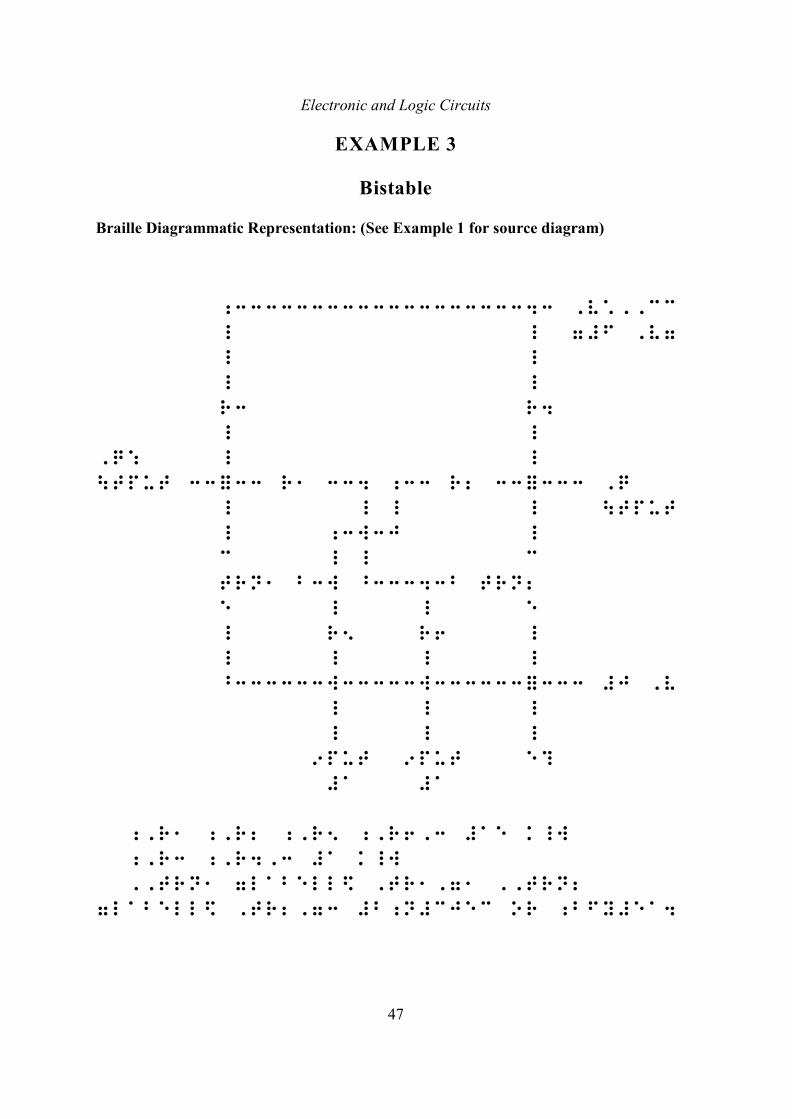
EXAMPLE 3
Bistable
Braille Diagrammatic Representation: (See Example 1 for source diagram)
;333333333333333333343 ,v*,,cc
_ _ 7#f ,v7
_ _
_ _
r3 r4
_ _
,q: _ _
\tput 33=33 r1 334 ;33 r2 33=333 ,q
_ _ _ _ \tput
_ ;3w3j _
c _ _ c
trn1 b3w ^33343b trn2
e _ _ e
_ r5 r6 _
_ _ _ _
^333333w33333w333333=333 #j ,v
_ _ _
_ _ _
9put 9put e?
#a #a
;,r1 ;,r2 ;,r5 ;,r6,3 #ae k_w
;,r3 ;,r4,3 #a k_w
,,trn1 7labell$ ,tr1,71 ,,trn2
7labell$ ,tr2,73 #b;n#cjec or ;bfy#ea4
Electronic and Logic Circuits
48
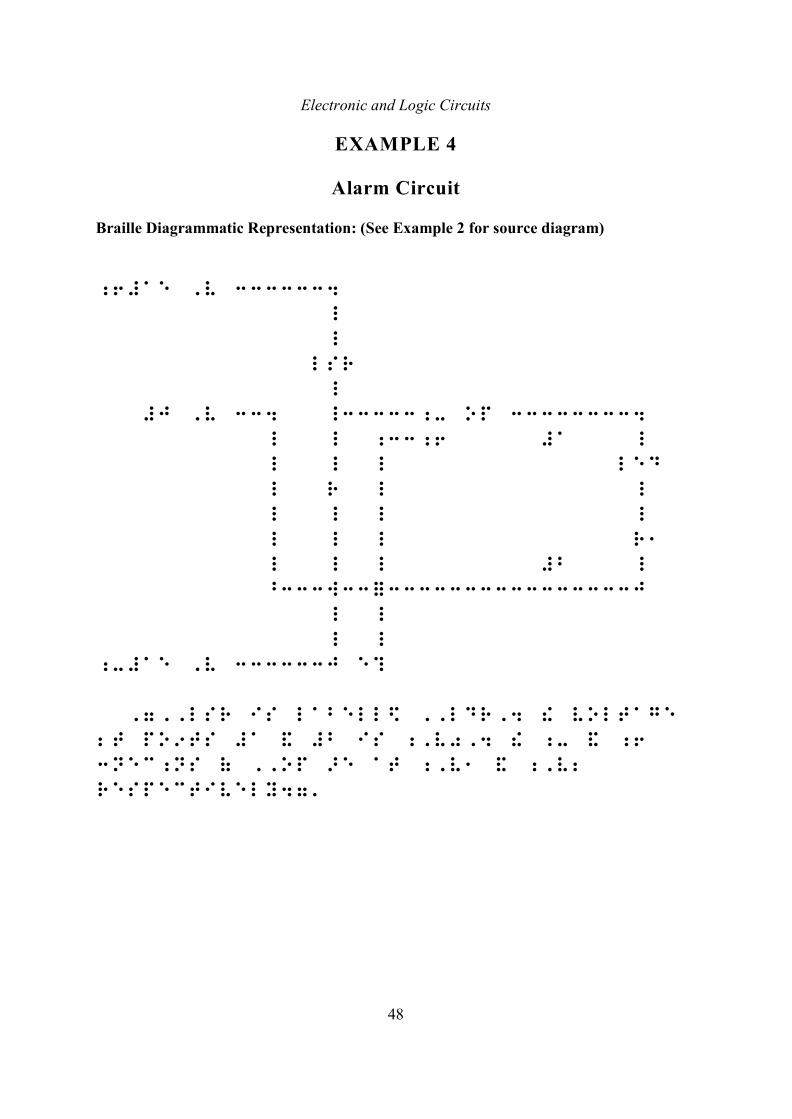
EXAMPLE 4
Alarm Circuit
Braille Diagrammatic Representation: (See Example 2 for source diagram)
;6#ae ,v 3333334
_
_
lsr
_
#j ,v 334 _33333;- op 333333334
_ _ ;33;6 #a _
_ _ _ led
_ r _ _
_ _ _ _
_ _ _ r1
_ _ _ #b _
^333w33=3333333333333333j
_ _
_ _
;-#ae ,v 333333j e?
,7,,lsr is labell$ ,,ldr,4 ! voltage
2t po9ts #a & #b is ;,v0,4 ! ;- & ;6
3nec;ns ( ,,op >e at ;,v1 & ;,v2
respectively47'
Electronic and Logic Circuits
49
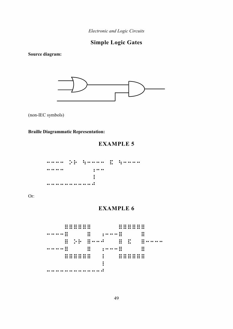
Simple Logic Gates
Source diagram:
(non-IEC symbols)
Braille Diagrammatic Representation:
EXAMPLE 5
3333 or \3333 & \3333
3333 ;33
_
3333333333j
Or:
EXAMPLE 6
====== ======
3333= = ;333= =
= or =33j = & =3333
3333= = ;333= =
====== _ ======
_
333333333333j
Electronic and Logic Circuits
50
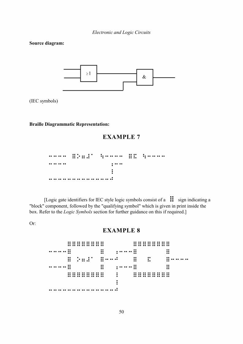
Source diagram:
(IEC symbols)
Braille Diagrammatic Representation:
EXAMPLE 7
3333 =o7#a \3333 =& \3333
3333 ;33
_
3333333333333j
[Logic gate identifiers for IEC style logic symbols consist of a = sign indicating a
"block" component, followed by the "qualifying symbol" which is given in print inside thebox. Refer to the Logic Symbols section for further guidance on this if required.]
Or:
EXAMPLE 8
======== ========
3333= = ;333= =
= o7#a =33j = & =3333
3333= = ;333= =
======== _ ========
_
33333333333333j
Electronic and Logic Circuits
51
2. BRAILLE DESCRIPTIVE REPRESENTATION
[Refer to examples 9, 10 and 11.]
In this method, the circuit is presented in two stages:
(a) Display of Components
This part shows the components, circuit terminals and external connections displayedas an array, set out approximately as they are shown in the print circuit. It should be the aimto keep the braille display compact, with components neatly aligned vertically. Componentswill normally be spaced in the array, but when it is necessary in order to fit a large arrayacross the page, it is acceptable to braille the components unspaced as long as there arenumerical subscripts to separate the identifying abbreviations (see below). Large arrays mayalso be divided into sections or brailled across facing pages where necessary: in such casesthis arrangement should be explained in a note beforehand. The array is preceded andfollowed by a centred line of three spaced asterisks.
Components are generally identified using the abbreviations given in Table A, withsubscript numbers distinguishing components of the same type, numbering components in theorder left to right across the rows, and taking the rows from top to bottom. Where acomponent has a label in the print which stems from the standard braille identifyingabbreviation, this print label may be used (with its attached print number or other affix ifpresent); otherwise the standard braille abbreviation should be used and the print labelexplained later.
Letter fount signs are not normally used before component identifiers in the displayeven when capital print labels are used for this purpose (since they may generally beunderstood to be such), though it may be necessary to use letter fount signs to show capital orother letter founts of letters attached to identifiers using the usual mathematics code letterfount sign conventions.
Components without a standard braille abbreviation should be identified by someother suitably chosen abbreviation. This may be derived from the component's name or be theprint label if not too long, but should be distinct from those listed in Table A as they refer tothose specific components. It may thus be necessary to explain such labels by descriptions oridentifying diagrams, in a preliminary note or elsewhere in the text.
Integrated circuits treated as individual components in a circuit may generally beidentified by the label IC (with affixed numbers etc. as necessary). The basic non-IEC logicgate symbols AND, OR, etc. have special identifiers. For simplicity, these identifiers mayalso be used in this method for the IEC equivalent symbols for such elementary (uncombined)gates, though it will generally be advisable to explain in a braille note that the other style ofsymbol is in fact used in the print. Refer to the section on Logic Symbols for general guidanceon logic symbol identifiers. Other components represented as blocks in print may either beidentified by a suitably chosen abbreviation which may again be derived from thecomponent's name or be its print label (if present) if it is distinct and not too long, or else be
identified by the general block identifier = , with affix as necessary (e.g. as are the master
Electronic and Logic Circuits
52
and slave flip-flops in example 11). Where necessary, these identifiers and any additionalinformation should be explained by descriptions or diagrams. In particular, complex logic
symbols are identified by = symbols which may be expanded by the method given in the
section on Logic Symbols, this expansion being placed with the information after the display,or else directly in a drawn out diagram.
Circuit terminals and other external connections are generally indicated by x
symbols, and distinguished by subscript numbers in the same way as components. Certainexternal connections such as aerial and earth have their own identifiers. External connectionswhich are labelled in print (e.g. a, b, c, etc.) may be labelled in the same way in the braille
without using the x symbol, if they are not too long. Letter fount signs should be used
when these labels are letters, to distinguish them from the standard abbreviations given in
Tables A and B. When it is not convenient to use such print labels in the display, the x
symbol should be used, with the print notation and other such information explained after thedisplay.
When the circuit does not derive from a print circuit, or is not intended to represent aprint circuit, this stage in the presentation may be dispensed with.
(b) Connection of Components, and Other Information
In this part, the connections between the components and terminals displayed in thearray are listed, together with additional information explaining the circuit. The information isarranged as a sequence of entries, each starting in cell 1 with runovers in cell 3.
The Additional Information
The additional informal information is given first. This may include the specification
of formal x and = signs used (e.g. the x 's as inputs or outputs; the = 's as being
of particular type); voltages of batteries or other connections; print component labels notgiven in the display or explained elsewhere (but not component values, which can betabulated later); explanation of special connections not described by the standardabbreviations; etc. Such information will usually be given as a single entry, with punctuationused as appropriate to separate the individual items. It may, however, be desirable to useseparate entries for longer items such as expansions of block identifiers using the methodexplained in the section on logic symbols, for clarity. Letter fount signs should be used whengiving such information according to the usual mathematics conventions.
Any x symbols should be shown as being capital, as are the standard braille
abbreviations given in Table A, even if they contain a braille contraction (apart from the =
sign, which is purely symbolic).
Electronic and Logic Circuits
53
The Terminal Identifiers
In order to specify the connections in the circuit, the terminals of components areidentified by appending a number or other label to component identifiers. Terminals listed inTable B are identified by the standard braille abbreviations given in that table; thus, for
example, b1;6 indicates the positive terminal of battery 1. Print labels may be used
for other terminals where given, but any ambiguities with the standard braille terminalabbreviations should be clarified in a preliminary note to the circuit presentation. It may benecessary to devise abbreviations to identify other special terminals: these may be explainedin the 'additional information' entry as described above, or in a preliminary note or key asconvenient. Terminal identifiers from Table B, or those devised for the purpose, will notrequire fount letter signs here unless it is necessary to separate letters A-J from a precedingnumber, in which case the dot 6 letter fount sign is used. When print labels are used for thispurpose, however, capital or other founts should be explicitly shown according to the usualmathematics code conventions, in order that the print be faithfully represented. Terminalswithout special names (e.g. the two terminals of a resistor) are identified by a lower number(without a numeral sign). When the component has two such terminals the convention oflabelling the top or left-hand terminal 1 and the bottom or right-hand terminal 2, shouldgenerally be adhered to. A lower number terminal identifier immediately following a lowernumber component identifier should be separated from it by a dot 3; thus, for example,
r2'1 indicates terminal 1 of resistor 2. If a lower number or other distinguishing affix
to the component identifier is absent (e.g. if there is only one component of that type in thecircuit), then the dot 3 separator should still be used before the lower number terminalidentifier. Thus if the circuit had only one resistor R, terminal 1 of that resistor would be
indicated as r'1 . Terminal abbreviations may themselves require numbers or other
labels appended in order to specify the terminals. For example, an OR logic symbol may have
two inputs, identified as orin1 and orin2 respectively.
Terminals of transformers are identified by first indicating the winding, then theconnection to the winding. The two ends of a winding should be numbered 1 and 2, andtappings numbered from 3 onwards. It will not normally be necessary to use the "tapping"abbreviation here with these conventions. Thus, for example, the second end of the first
winding of transformer 3 would be indicated by t3'1'2 .
Stating the Circuit Connections
The connections in the circuit are given in a number of sequences. Each sequenceconsists of those terminals which are directly connected, with the individual terminal
identifiers in the sequence separated by dot 5's; thus, for example, b1;6"r2'1 ,
indicates that the positive terminal of battery 1 is connected to terminal 1 of resistor 2. Eachsequence is normally treated as a separate cell 1 entry (with runovers in cell 3), though whenthere are several short sequences giving analogous connections (as frequently occur with
Electronic and Logic Circuits
54
complex digital circuits), those sequences may be advantageously placed in a single entry,leaving a blank cell between sequences. It may also be possible to use hyphens to state such
cases compactly. For example, ic2'1-ic2'10"c1'2 will mean
2 1pins 1 to 10 of IC are connected to terminal 2 of C .In general one should try to be fairly systematic in the order in which the connections
in the circuit are given. Thus for a complex electronic circuit one might work across thecircuit in 'rows' from left to right, and take 'rows' in order from the top-most to thebottom-most, i.e. scanning the circuit as if reading a page, though this will clearly only be anapproximate scheme.
Component values are tabulated beneath the connection entries, after a blank line.The descriptive representation of the circuit is finished with a centred line of 12 dot
2's.
Electronic and Logic Circuits
55
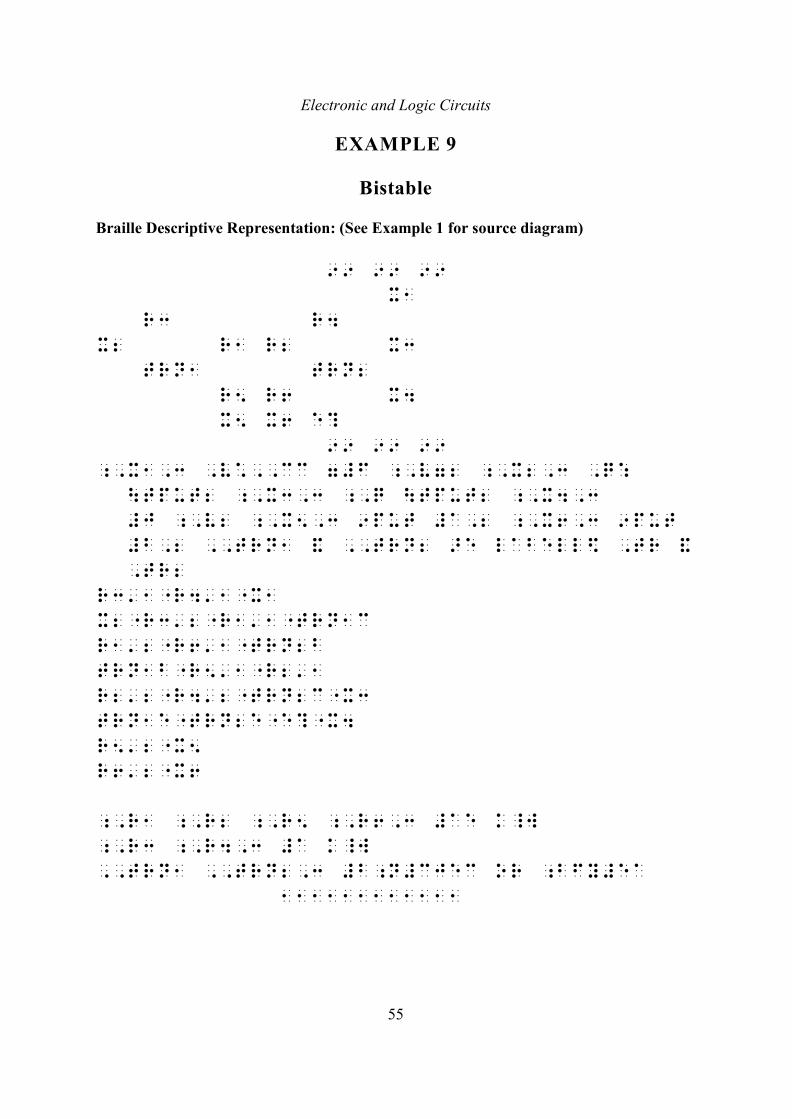
EXAMPLE 9
Bistable
Braille Descriptive Representation: (See Example 1 for source diagram)
99 99 99
x1
r3 r4
x2 r1 r2 x3
trn1 trn2
r5 r6 x4
x5 x6 e?
99 99 99
;,x1,3 ,v*,,cc 7#f ;,v72 ;,x2,3 ,q:
\tput2 ;,x3,3 ;,q \tput2 ;,x4,3
#j ;,v2 ;,x5,3 9put #a,2 ;,x6,3 9put
#b,2 ,,trn1 & ,,trn2 >e labell$ ,tr &
,tr2
r3'1"r4'1"x1
x2"r3'2"r1'1"trn1c
r1'2"r6'1"trn2b
trn1b"r5'1"r2'1
r2'2"r4'2"trn2c"x3
trn1e"trn2e"e?"x4
r5'2"x5
r6'2"x6
;,r1 ;,r2 ;,r5 ;,r6,3 #ae k_w
;,r3 ;,r4,3 #a k_w
,,trn1 ,,trn2,3 #b;n#cjec or ;bfy#ea
111111111111
Electronic and Logic Circuits
56
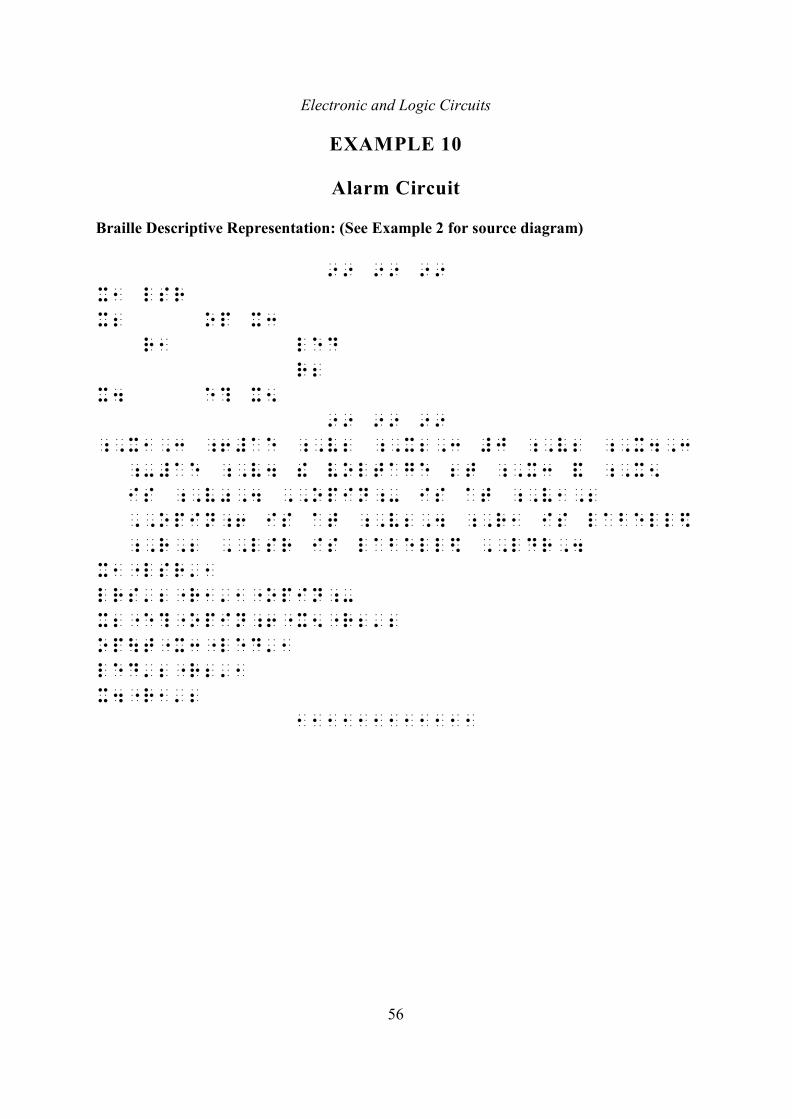
EXAMPLE 10
Alarm Circuit
Braille Descriptive Representation: (See Example 2 for source diagram)
99 99 99
x1 lsr
x2 op x3
r1 led
r2
x4 e? x5
99 99 99
;,x1,3 ;6#ae ;,v2 ;,x2,3 #j ;,v2 ;,x4,3
;-#ae ;,v4 ! voltage 2t ;,x3 & ;,x5
is ;,v0,4 ,,opin;- is at ;,v1,2
,,opin;6 is at ;,v2,4 ;,r1 is labell$
;,r,2 ,,lsr is labell$ ,,ldr,4
x1"lsr'1
lrs'2"r1'1"opin;-
x2"e?"opin;6"x5"r2'2
op\t"x3"led'1
led'2"r2'1
x4"r1'2
111111111111
Electronic and Logic Circuits
57
LOGIC SYMBOLS
The following gives conventions for assigning component and terminal identifiers forlogic symbols, to be used in the Diagrammatic Representation methods (ii) and (iii), and theBraille Descriptive Representation.
Logic symbols are graphical representations of logic functions. They are usedprimarily in digital electronics, but have general application in other engineering disciplines.The international standard (IEC standard) for such symbols is that they be represented byrectangular boxes (with various qualifying symbols), but the alternative convention ofrepresenting basic logic gates (e.g. AND, OR, etc.) by particular shaped symbols as given inTable C is still widespread.
Table A gives the standard braille abbreviations to be used to represent the basic logicgates when the non-IEC symbol is used in print. For simplicity, these abbreviations can alsobe used for such elementary (uncombined) gates in the Braille Descriptive Representationwhen the IEC symbol is used in print, as this avoids the necessity of identifying blocksymbols representing them in a key. However, if this is done, it will generally be advisable toexplain in a braille note that the other style of symbol is in fact used in the print. Otherwise,logic symbols should generally be treated according to the following conventions.
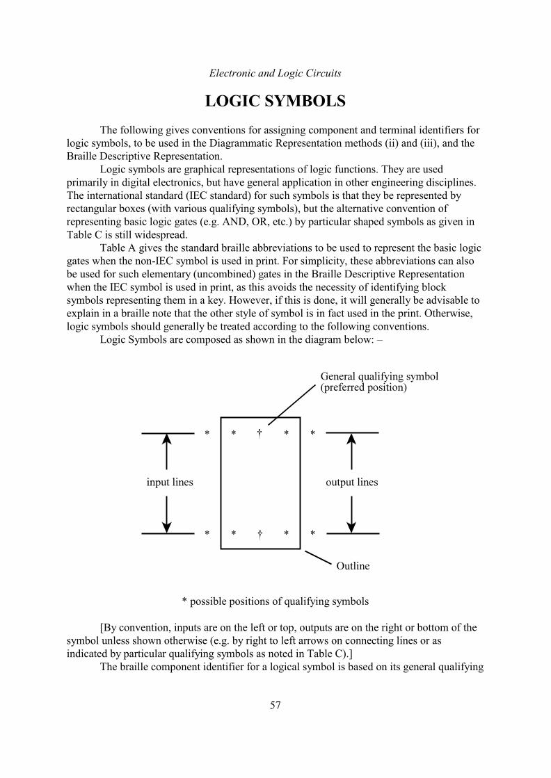
Logic Symbols are composed as shown in the diagram below: –
* possible positions of qualifying symbols
[By convention, inputs are on the left or top, outputs are on the right or bottom of thesymbol unless shown otherwise (e.g. by right to left arrows on connecting lines or asindicated by particular qualifying symbols as noted in Table C).]
The braille component identifier for a logical symbol is based on its general qualifying
Electronic and Logic Circuits
58
symbol; that is, the identifier consists of the full cell = followed by that qualifying symbol
if it is directly transcribable, or by an abbreviation representing it if it is graphical, plus anumerical subscript to distinguish similar symbols in the diagram, if necessary for the BrailleDescriptive Representation. (When the outline is given in a diagrammatic representation theinitial full cell is not required.) Those abbreviations given in Table A should be used for thesymbols listed; in other cases suitable abbreviations should be devised for the purpose. If thequalifying symbol contains a space, then it should be placed in mathematical brackets in thecomponent identifier when appending the full cell.
For diagrammatic representations, terminals are labelled by their qualifying symbol(s)if present (marked * in the diagram on P.57) when directly transcribable, or by abbreviationsrepresenting them if they are graphical. Those abbreviations given in Table B should be usedfor the symbols listed; in other cases suitable abbreviations should be devised for the purpose.When the outline is not shown and a terminal has both external and internal qualifyingsymbols to the outline, they should be separated by a semicolon (followed by a space) withthe group enclosed in mathematical brackets. If the outline is shown, then the qualifyingsymbols should be placed inside or outside the outline as shown in print.
For the Braille Descriptive Representation the terminal identifiers consist of thecomponent identifier followed by the input or output abbreviation as appropriate; with anumerical subscript, or other such label if given in print, to distinguish different inputs oroutputs to the symbol if necessary; appended with the qualifying symbol(s) on the terminal asabove (if present). Mathematical brackets are used for terminal qualifying symbols containinga space as with general qualifying symbols. When a terminal has both external and internalqualifying symbols to the outline, they should be separated by a semicolon (followed by aspace), and brackets enclosing the qualifying group will be necessary.
Standard braille abbreviations for qualifying symbols given in Tables A and B will notrequire letter fount signs unless it is necessary to separate a letter A-J from a precedingnumber, in which case the dot 6 letter fount sign is used. Print qualifying symbols and otherlabelling transcribed directly, however, will require letter fount signs in accordance with theusual mathematics code conventions, unless the print conventions are otherwise made clearbeforehand. (Qualifying abbreviations are, in fact, generally in capitals in print.)
Electronic and Logic Circuits
59
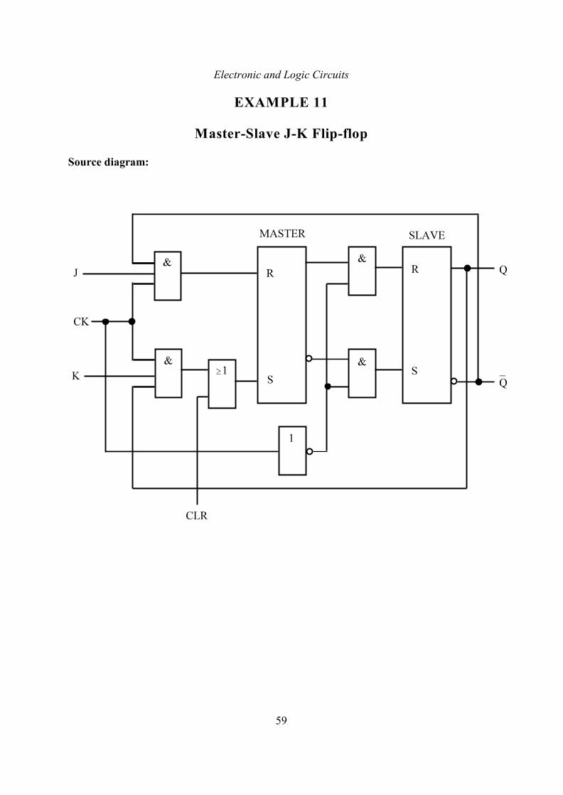
EXAMPLE 11
Master-Slave J-K Flip-flop
Source diagram:
Electronic and Logic Circuits
60
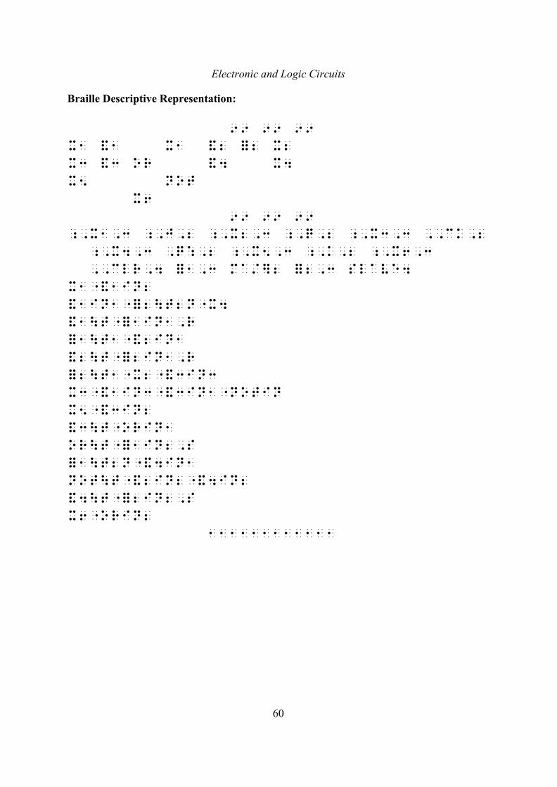
Braille Descriptive Representation:
99 99 99
x1 &1 x1 &2 =2 x2
x3 &3 or &4 x4
x5 not
x6
99 99 99
;,x1,3 ;,j,2 ;,x2,3 ;,q,2 ;,x3,3 ,,ck,2
;,x4,3 ,q:,2 ;,x5,3 ;,k,2 ;,x6,3
,,clr,4 =1,3 ma/]2 =2,3 slave4
x1"&1in2
&1in1"=2\t2n"x4
&1\t"=1in1,r
=1\t1"&2in1
&2\t"=2in1,r
=2\t1"x2"&3in3
x3"&1in3"&3in1"notin
x5"&3in2
&3\t"orin1
or\t"=1in2,s
=1\t2n"&4in1
not\t"&2in2"&4in2
&4\t"=2in2,s
x6"orin2
111111111111
Electronic and Logic Circuits
61
Composite Logic Symbols
As a means of simplifying diagrams, logic symbols may be shown juxtaposed within asingle rectangular outline to form a composite logic symbol. It is the convention that logicsymbols are only connected across vertical junctions, not horizontal junctions, within suchcomposite symbols. With the diagrammatic methods of representation, it is best for suchcomposite symbols to be represented with their outlines and internal lines shown, and thentreated in the same way as non-composite logic symbols. The following techniques are onlyrequired for the braille descriptive method of representation.
In the display of components in the Braille Descriptive Representation, composite
logic symbols should be shown simply by a full cell = with a distinguishing subscript
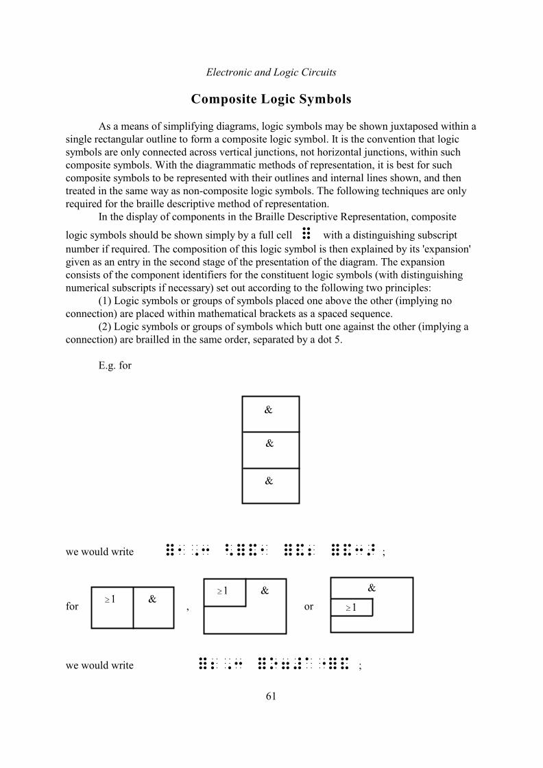
number if required. The composition of this logic symbol is then explained by its 'expansion'given as an entry in the second stage of the presentation of the diagram. The expansionconsists of the component identifiers for the constituent logic symbols (with distinguishingnumerical subscripts if necessary) set out according to the following two principles:
(1) Logic symbols or groups of symbols placed one above the other (implying noconnection) are placed within mathematical brackets as a spaced sequence.
(2) Logic symbols or groups of symbols which butt one against the other (implying aconnection) are brailled in the same order, separated by a dot 5.
E.g. for
we would write =1,3 <=&1 =&2 =&3> ;
for , or
we would write =2,3 =o7#a"=& ;
Electronic and Logic Circuits
62
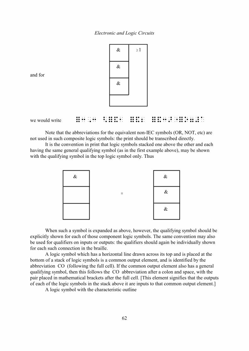
and for
we would write =3,3 <=&1 =&2 =&3>"=o7#a
Note that the abbreviations for the equivalent non-IEC symbols (OR, NOT, etc) arenot used in such composite logic symbols: the print should be transcribed directly.
It is the convention in print that logic symbols stacked one above the other and eachhaving the same general qualifying symbol (as in the first example above), may be shownwith the qualifying symbol in the top logic symbol only. Thus
/
When such a symbol is expanded as above, however, the qualifying symbol should beexplicitly shown for each of those component logic symbols. The same convention may alsobe used for qualifiers on inputs or outputs: the qualifiers should again be individually shownfor each such connection in the braille.
A logic symbol which has a horizontal line drawn across its top and is placed at thebottom of a stack of logic symbols is a common output element, and is identified by theabbreviation CO (following the full cell). If the common output element also has a generalqualifying symbol, then this follows the CO abbreviation after a colon and space, with thepair placed in mathematical brackets after the full cell. [This element signifies that the outputsof each of the logic symbols in the stack above it are inputs to that common output element.]
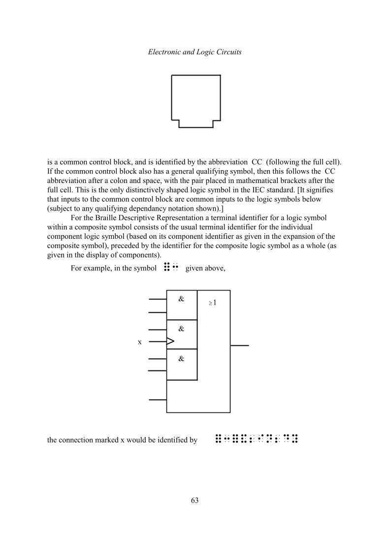
A logic symbol with the characteristic outline
Electronic and Logic Circuits
63
is a common control block, and is identified by the abbreviation CC (following the full cell).If the common control block also has a general qualifying symbol, then this follows the CC abbreviation after a colon and space, with the pair placed in mathematical brackets after thefull cell. This is the only distinctively shaped logic symbol in the IEC standard. [It signifiesthat inputs to the common control block are common inputs to the logic symbols below(subject to any qualifying dependancy notation shown).]
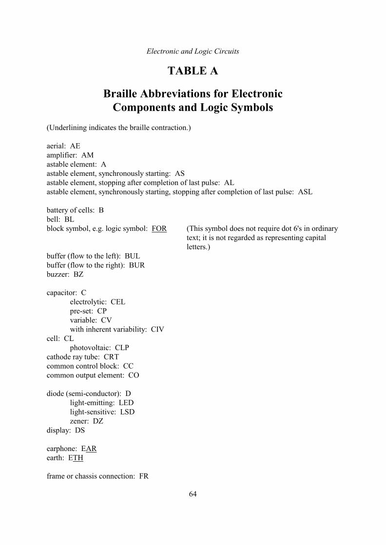
For the Braille Descriptive Representation a terminal identifier for a logic symbolwithin a composite symbol consists of the usual terminal identifier for the individualcomponent logic symbol (based on its component identifier as given in the expansion of thecomposite symbol), preceded by the identifier for the composite logic symbol as a whole (asgiven in the display of components).
For example, in the symbol =3 given above,
the connection marked x would be identified by =3=&2in2dy
Electronic and Logic Circuits
64
TABLE A
Braille Abbreviations for ElectronicComponents and Logic Symbols
(Underlining indicates the braille contraction.)
aerial: AEamplifier: AMastable element: Aastable element, synchronously starting: ASastable element, stopping after completion of last pulse: ALastable element, synchronously starting, stopping after completion of last pulse: ASL
battery of cells: Bbell: BLblock symbol, e.g. logic symbol: FOR (This symbol does not require dot 6's in ordinary
text; it is not regarded as representing capitalletters.)
buffer (flow to the left): BULbuffer (flow to the right): BURbuzzer: BZ
capacitor: Celectrolytic: CELpre-set: CPvariable: CVwith inherent variability: CIV
cell: CLphotovoltaic: CLP
cathode ray tube: CRTcommon control block: CCcommon output element: CO
diode (semi-conductor): Dlight-emitting: LEDlight-sensitive: LSDzener: DZ
display: DS
earphone: EARearth: ETH
frame or chassis connection: FR
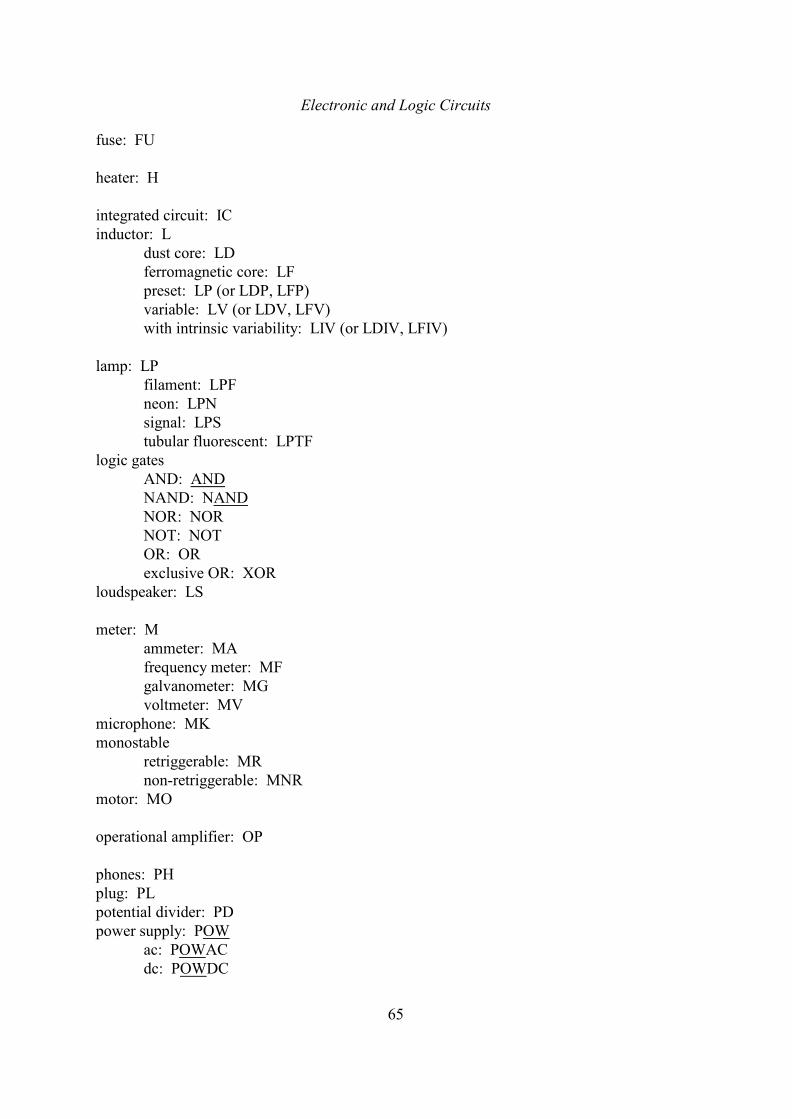
Electronic and Logic Circuits
65
fuse: FU
heater: H
integrated circuit: ICinductor: L
dust core: LDferromagnetic core: LFpreset: LP (or LDP, LFP)variable: LV (or LDV, LFV)with intrinsic variability: LIV (or LDIV, LFIV)
lamp: LPfilament: LPFneon: LPNsignal: LPStubular fluorescent: LPTF
logic gatesAND: ANDNAND: NANDNOR: NORNOT: NOTOR: ORexclusive OR: XOR
loudspeaker: LS
meter: Mammeter: MAfrequency meter: MFgalvanometer: MGvoltmeter: MV
microphone: MKmonostable
retriggerable: MRnon-retriggerable: MNR
motor: MO
operational amplifier: OP
phones: PHplug: PLpotential divider: PDpower supply: POW
ac: POWACdc: POWDC
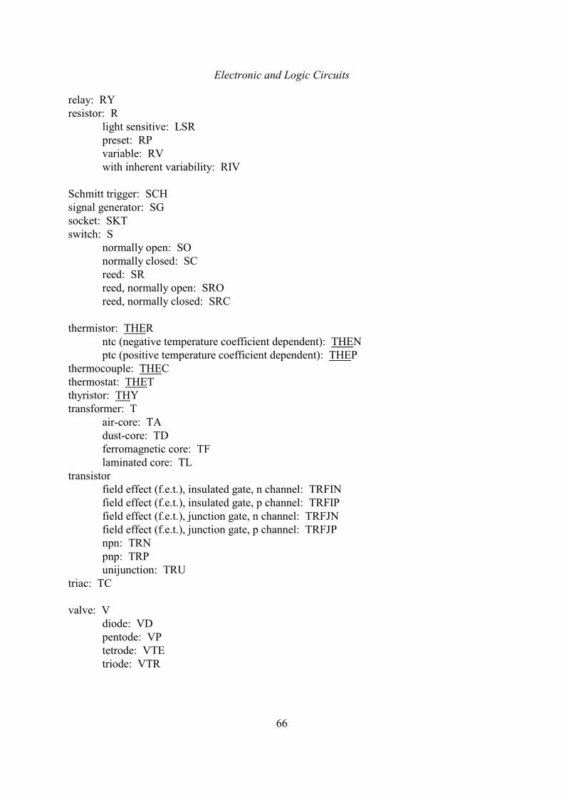
Electronic and Logic Circuits
66
relay: RYresistor: R
light sensitive: LSRpreset: RPvariable: RVwith inherent variability: RIV
Schmitt trigger: SCHsignal generator: SGsocket: SKTswitch: S
normally open: SOnormally closed: SCreed: SRreed, normally open: SROreed, normally closed: SRC
thermistor: THERntc (negative temperature coefficient dependent): THENptc (positive temperature coefficient dependent): THEP
thermocouple: THECthermostat: THETthyristor: THYtransformer: T
air-core: TAdust-core: TDferromagnetic core: TFlaminated core: TL
transistorfield effect (f.e.t.), insulated gate, n channel: TRFINfield effect (f.e.t.), insulated gate, p channel: TRFIPfield effect (f.e.t.), junction gate, n channel: TRFJNfield effect (f.e.t.), junction gate, p channel: TRFJPnpn: TRNpnp: TRPunijunction: TRU
triac: TC
valve: Vdiode: VDpentode: VPtetrode: VTEtriode: VTR
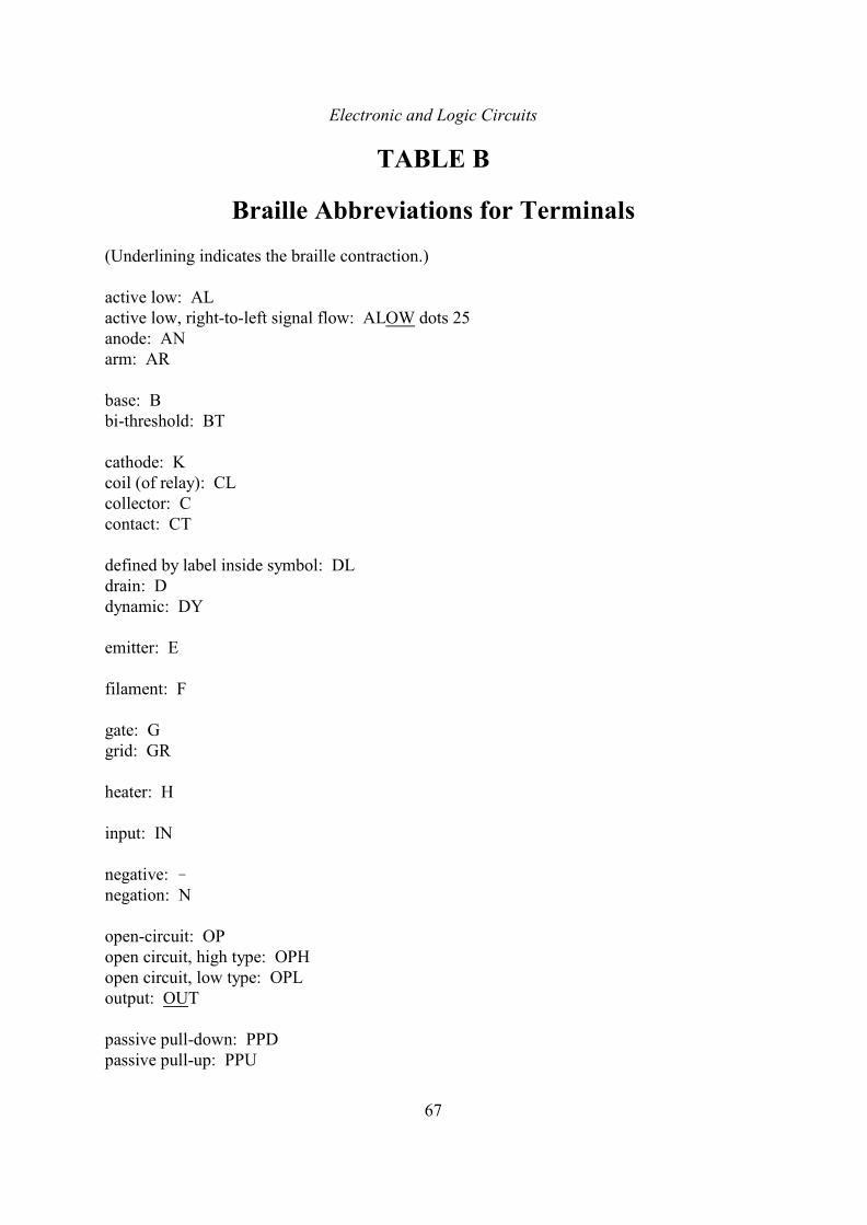
Electronic and Logic Circuits
67
TABLE B
Braille Abbreviations for Terminals
(Underlining indicates the braille contraction.)
active low: ALactive low, right-to-left signal flow: ALOW dots 25anode: ANarm: AR
base: Bbi-threshold: BT
cathode: Kcoil (of relay): CLcollector: Ccontact: CT
defined by label inside symbol: DLdrain: Ddynamic: DY
emitter: E
filament: F
gate: Ggrid: GR
heater: H
input: IN
negative: !negation: N
open-circuit: OPopen circuit, high type: OPHopen circuit, low type: OPLoutput: OUT
passive pull-down: PPDpassive pull-up: PPU

Electronic and Logic Circuits
68
positive: +postponed: PO
source: Ssubstrate: SSTsupply: SUP
tapping: T3-state: 3S
wiper: W
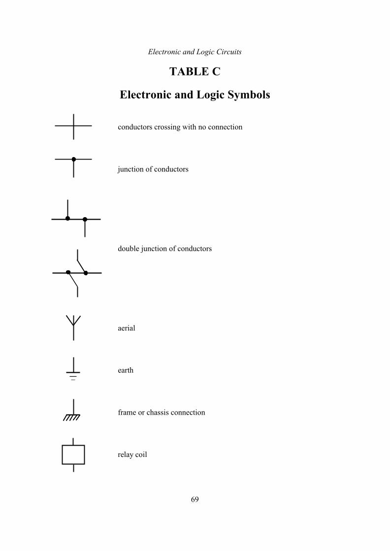
Electronic and Logic Circuits
69
TABLE C
Electronic and Logic Symbols
conductors crossing with no connection
junction of conductors
double junction of conductors
aerial
earth
frame or chassis connection
relay coil
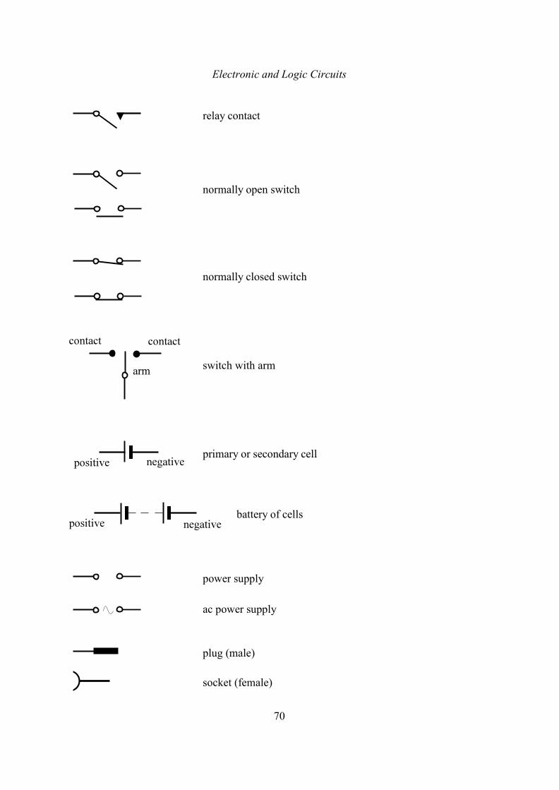
Electronic and Logic Circuits
70
relay contact
normally open switch
normally closed switch
switch with arm
primary or secondary cell
battery of cells
power supply
ac power supply
plug (male)
socket (female)
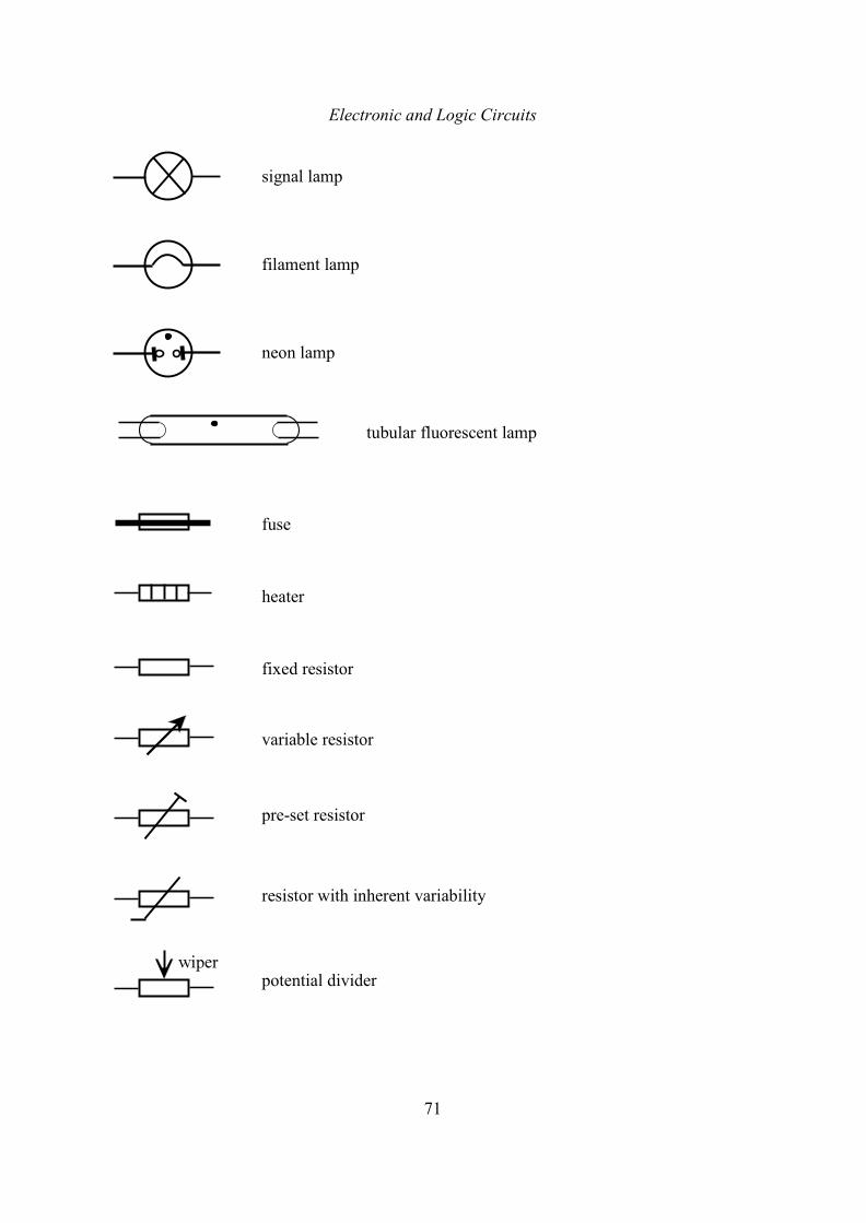
Electronic and Logic Circuits
71
signal lamp
filament lamp
neon lamp
tubular fluorescent lamp
fuse
heater
fixed resistor
variable resistor
pre-set resistor
resistor with inherent variability
potential divider
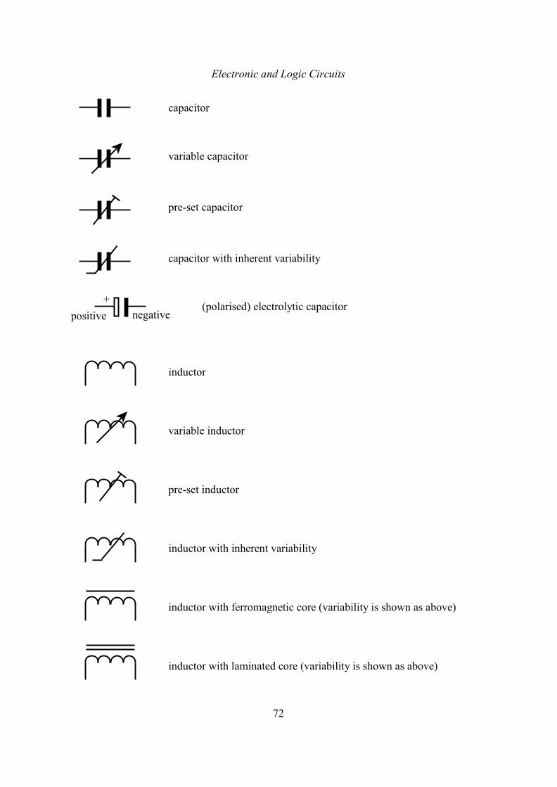
Electronic and Logic Circuits
72
capacitor
variable capacitor
pre-set capacitor
capacitor with inherent variability
(polarised) electrolytic capacitor
inductor
variable inductor
pre-set inductor
inductor with inherent variability
inductor with ferromagnetic core (variability is shown as above)
inductor with laminated core (variability is shown as above)
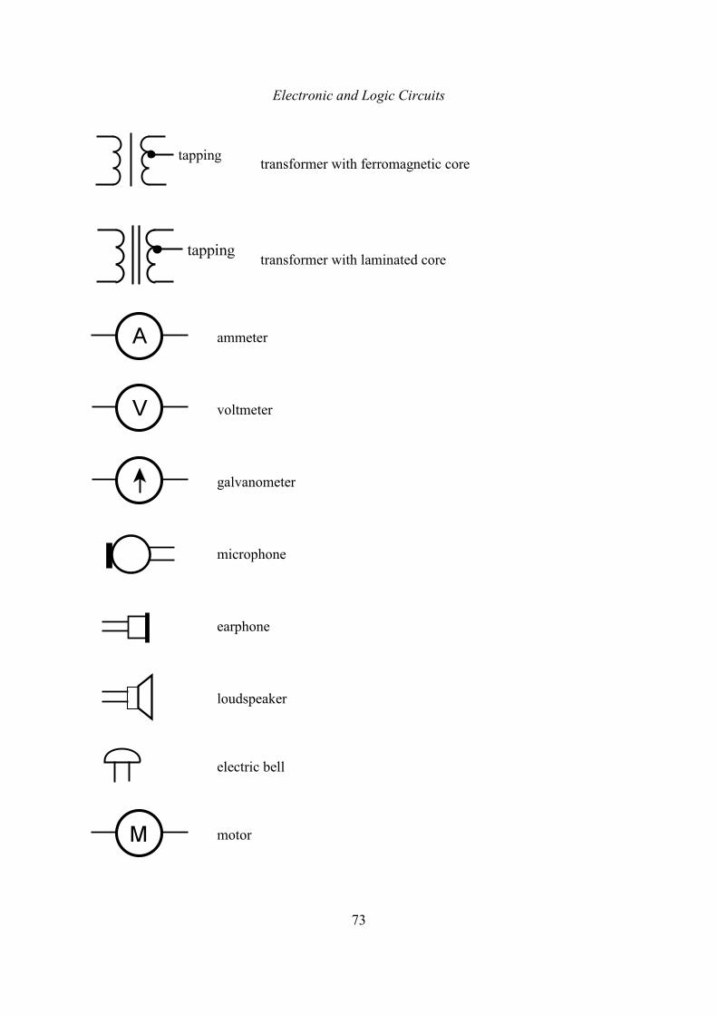
Electronic and Logic Circuits
73
transformer with ferromagnetic core
transformer with laminated core
ammeter
voltmeter
galvanometer
microphone
earphone
loudspeaker
electric bell
motor
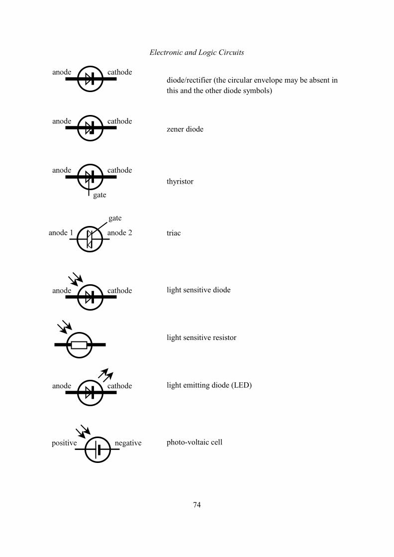
Electronic and Logic Circuits
74
diode/rectifier (the circular envelope may be absent in
this and the other diode symbols)
zener diode
thyristor
triac
light sensitive diode
light sensitive resistor
light emitting diode (LED)
photo-voltaic cell
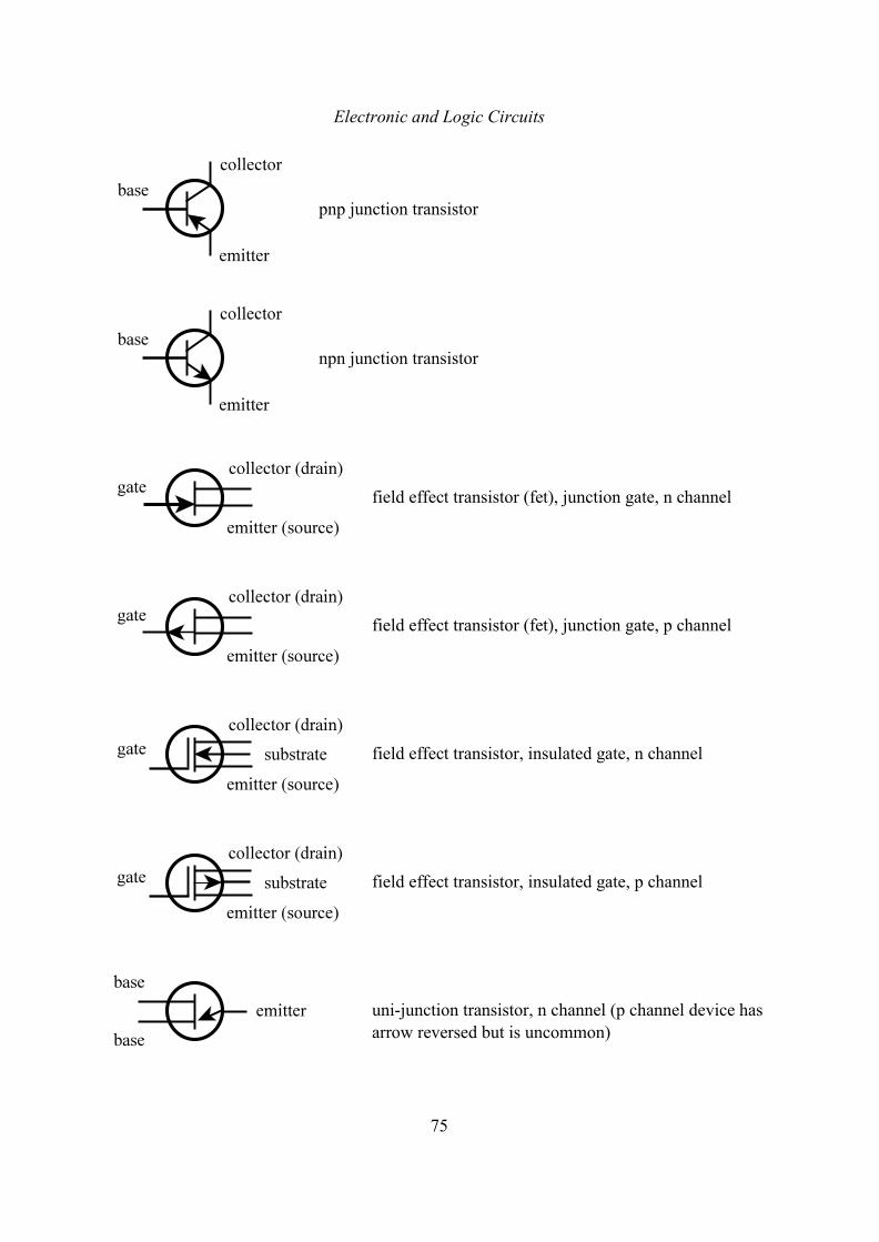
Electronic and Logic Circuits
75
pnp junction transistor
npn junction transistor
field effect transistor (fet), junction gate, n channel
field effect transistor (fet), junction gate, p channel
field effect transistor, insulated gate, n channel
field effect transistor, insulated gate, p channel
uni-junction transistor, n channel (p channel device has
arrow reversed but is uncommon)
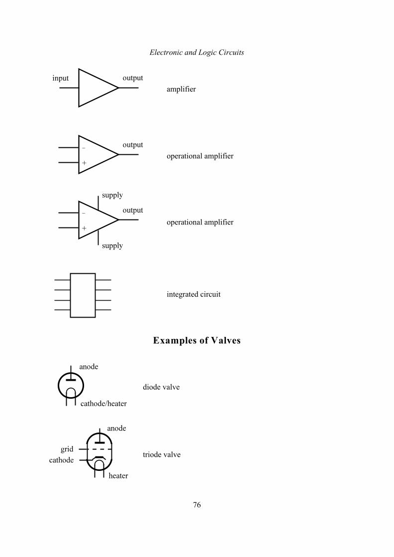
Electronic and Logic Circuits
76
amplifier
operational amplifier
operational amplifier
integrated circuit
Examples of Valves
diode valve
triode valve
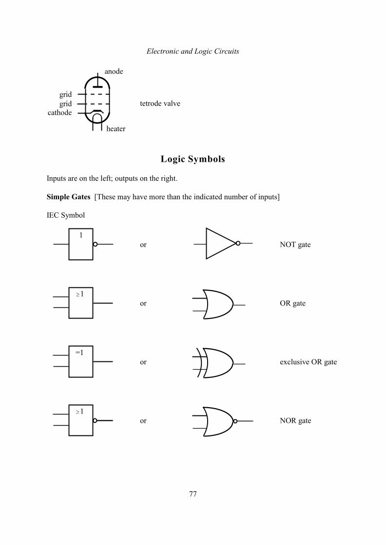
Electronic and Logic Circuits
77
tetrode valve
Logic Symbols
Inputs are on the left; outputs on the right.
Simple Gates [These may have more than the indicated number of inputs]
IEC Symbol
or NOT gate
or OR gate
or exclusive OR gate
or NOR gate
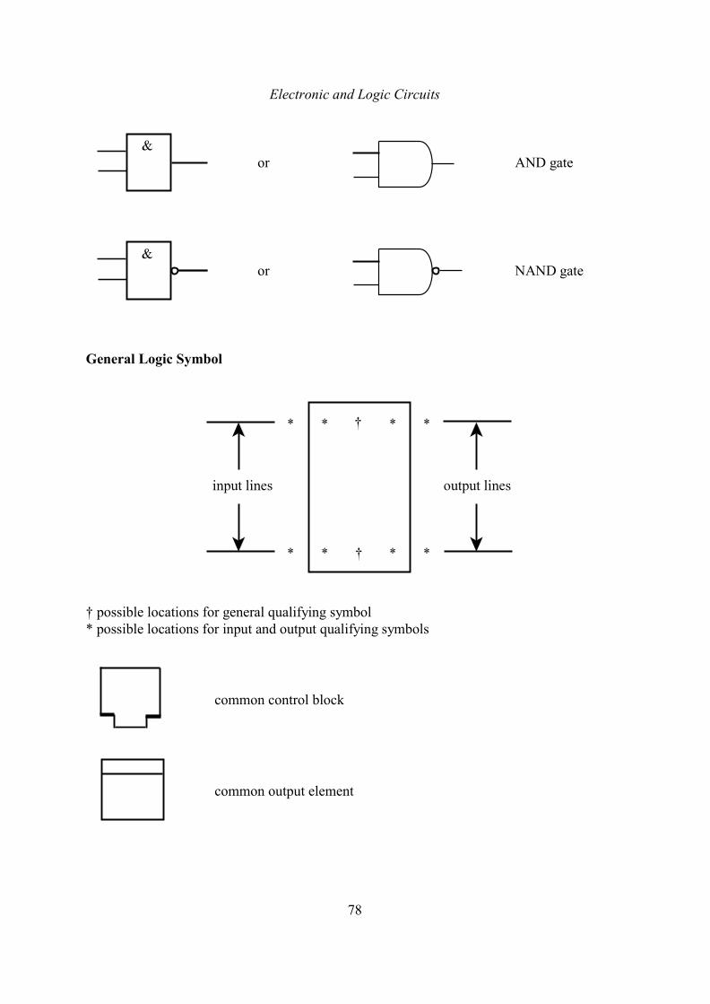
Electronic and Logic Circuits
78
or AND gate
or NAND gate
General Logic Symbol
† possible locations for general qualifying symbol* possible locations for input and output qualifying symbols
common control block
common output element
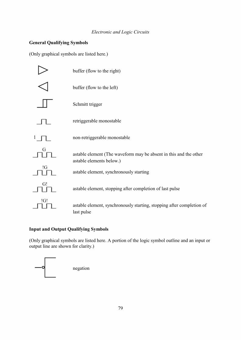
Electronic and Logic Circuits
79
General Qualifying Symbols
(Only graphical symbols are listed here.)
buffer (flow to the right)
buffer (flow to the left)
Schmitt trigger
retriggerable monostable
non-retriggerable monostable
astable element (The waveform may be absent in this and the other
astable elements below.)
astable element, synchronously starting
astable element, stopping after completion of last pulse
astable element, synchronously starting, stopping after completion of
last pulse
Input and Output Qualifying Symbols
(Only graphical symbols are listed here. A portion of the logic symbol outline and an input oroutput line are shown for clarity.)
negation
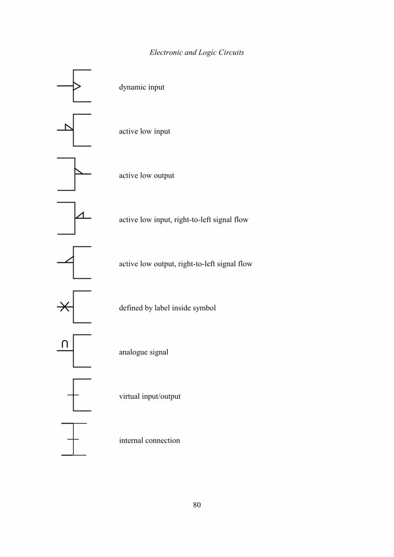
Electronic and Logic Circuits
80
dynamic input
active low input
active low output
active low input, right-to-left signal flow
active low output, right-to-left signal flow
defined by label inside symbol
analogue signal
virtual input/output
internal connection
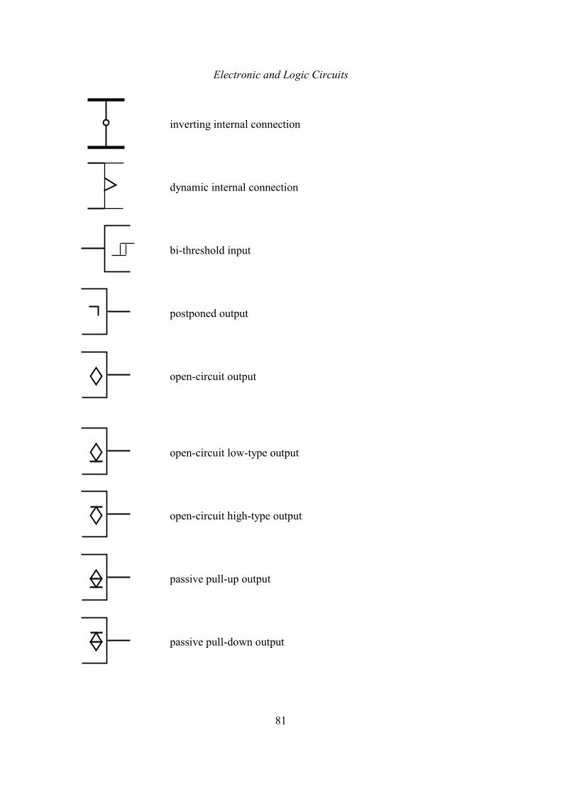
Electronic and Logic Circuits
81
inverting internal connection
dynamic internal connection
bi-threshold input
postponed output
open-circuit output
open-circuit low-type output
open-circuit high-type output
passive pull-up output
passive pull-down output
Electronic and Logic Circuits
82
3-state output
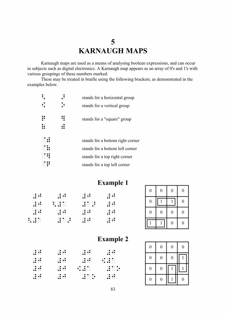
83
5KARNAUGH MAPS
Karnaugh maps are used as a means of analysing boolean expressions, and can occurin subjects such as digital electronics. A Karnaugh map appears as an array of 0's and 1's withvarious groupings of these numbers marked.
These may be treated in braille using the following brackets, as demonstrated in theexamples below.
< > stands for a horizontal group
[ o stands for a vertical group
q ] stands for a "square" group
( )
@) stands for a bottom right corner
@( stands for a bottom left corner
@] stands for a top right corner
@q stands for a top left corner
Example 1
#j #j #j #j
#j <#a #a> #j
#j #j #j #j
<#a #a> #j #j
Example 2
#j #j #j #j
#j #j #j {#a
#j #j {#a #ao
#j #j #ao #j
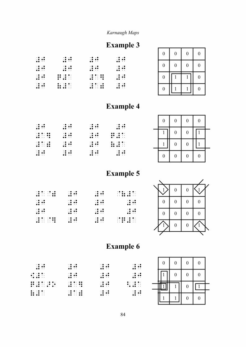
Karnaugh Maps
84
Example 3
#j #j #j #j
#j #j #j #j
#j q#a #a] #j
#j (#a #a) #j
Example 4
#j #j #j #j
#a] #j #j q#a
#a) #j #j (#a
#j #j #j #j
Example 5
#a@) #j #j @(#a
#j #j #j #j
#j #j #j #j
#a@] #j #j @q#a
Example 6
#j #j #j #j
{#a #j #j #j
q#a>o #a] #j <#a
(#a #a) #j #j