bronco ii misc info.pdf
DESCRIPTION
Misc info on the Ford Bronco 2TRANSCRIPT

Coil Springs: 101
OK, the subject came up, so I thought I'd Share
Coil springs are a wound up torsion bars.
The three things that change there spring rate is wire diameter, spring length (not the same as spring height) and coil pitch.
Wire Diameter is the thickness of the wire that the coil spring is made from.It is generally stated in thousands of an inch; as in .625 or .810.If a pair of springs have the same spring wire length but one .625 and the other .810the .625 spring will be much softer
Spring Length is the length of the wire coiled into a spring .If you have two springs with 15 inches of height, each with the same wire diameterone will have 10 coils and the other will have 12 coils. The one with the 12 coils will be softer.
There are two reasons for this. The first is spring length; you have 20% more wire to put the weight through. The second is coil pitch; as you put the coils closer together it puts more leverage on those coils.
That's how they make variable rate coil springs, by putting some coils close together and other coils further apart.
Oh, and a spring's rate is measured in pounds per inch (in./lbs.).
If a spring's rate is 400 in./lbs., it takes 400lbs. to compress a spring 1 inch and 800lbs. for 2 inches of compression..

One Man Brake Bleeder
I decided to make a 1 man brake bleeder after I swapped my front axle. i have a lot of air in my lines, and I didn't like spraying brake fluid everywhere, so this works out great.
Supplies-piece of flexible hose the size of bleeder nipple-short piece of hard tubing to fit inside hose ( i used a piece of a bic pen)-silicone caulk (or glue)-20 oz soda bottle-razor blade
First cut a hole in soda cap the size of the hard tubing. then slip a short piece of hose over the hard tubing.
Push the hard tubing through the cap with the short piece of tubing on the inside. Then push the rest of the tubing on the other side and seal with silicone (or glue).
Then just screw on the cap and cut a hole in the bottom of the bottle (now the top of the bleeder).
To use, just loosen your bleeder screw, attach hose, and either tie/tape the bottle to something nearby (like the coil spring), or have a buddy hold it (if available). Fill bottle partway with brake fluid through the hole you cut, then go pump your brakes as long as needed. When done, tighten bleeder screw with the hose still attached, then quickly remove hose and drain excess fluid back into brake fluid bottle.

Ford EEC-IV, and TFI Diagnostics Manual
Table of Contents:
Self-Diagnostics Terminal Setup…………………………………………………...1 Code erasing…………………………………………………………………………2Two Digit Test Codes……………………………………………………………….3Three Digit Test Codes……………………………………………………………..4Abbreviations and Definitions……………………………………………………….5TPS Calibration………………………………………………………………………6Base Idle Adjustment………………………………………………………………..7Oxygen Sensor Testing……………………………………………………………..8TFI Module Testing………………………………………………………………….9 ACT/ECT Test………………………………………………………………………10TFI Timing Procedure………………………………………………………………11IAC Cleaning and Testing………………………………………………………….12FPR Testing…………………………………………………………………………13Knock Sensor……………………………………………………………………….14MAP Test……………………………………………………………………………15

Self-Diagnostics Terminal Setup (1) On the passenger’s side, under the hood, there is the computer’s self-diagnostics output terminal. It is usually red or gray in color, and has a distinctive shape as shown below. An easy way to utilize this terminal without an expensive scan tool is with an analog multi-meter, set on DC Voltage (20V setting, or nearest equivalent). The Positive lead of the multi-meter can be attached to the battery’s (+) terminal, and the negative lead of the multi-meter can be attached to the connection as below. A jumper wire is also necessary (as below).
Scanning the codes. You want to make sure the engine is fully warmed up, automatic transmission in park, or manual transmission in neutral, with the parking brake on, or the wheels blocked. Once the multi-meter is attached, turn the ignition on, and watch the needle. Codes will be displayed as needle sweeps in groups of 2 or 3, followed by a 6 second delay. A 2 or three digit code will be several quick sweeps (1-9) followed by a 1 second pause, than the next number. These are referred to as memory codes. This test is complete when code 11 (system pass) has been displayed.
Running codes are done after this. The engine is started and left running. The code reader will flash twice (for a four cylinder) three times (for a 6 cylinder), four times (for and 8 cylinder), and five times (for a diesel). The computer will test items, including the timing. A timing light may also bee hooked up, and the timing should advance by 20 degrees during this test. Eventually there will be a single quick sweep of the needle; this is the throttle goose test. When this happens, the throttle must be depressed (a minimum) of 25%. The codes will be soon to follow, as per the previous test.
Erasing Codes (2)
Codes automatically erase after 60-100 starts. Starting the memory test procedure, and unplugging the connections erases memory codes. Disconnecting the battery will also erase all the codes; however, this may trigger a code 19 (loss of PCM power).

Two Digit Codes: (3) 11 System checks OK -
12 Idle Speed Control motor or Air Bypass not controlling idle properly (generally idle too low) - ISC
13 (O) ISC did not respond properly (extends to touch throttle then retracts for KOEO) - ISC
(R) Idle Speed Control motor or Air Bypass not controlling idle properly (generally idle too high)
(M) ISC sticking, open ITS circuit or TP sticking
14 Ignition pickup was erratic - Ignition Systems
E4OD Transmission diesel RPM sensor - Diesel RPM sensor
15 (O) No Keep Alive Memory power to PCM pin 1 or bad PCM (Memory Test Failure)
(M) KAM (pin 1) was interrupted (was battery disconnected ?)
16 1.9L & 2.5L - Throttle stop set too high - IDLE or Idle Set Procedures
2.3L - RPM's too low - IDLE
(O) Electronic ignition - IDM circuit fault - Ignition Systems
17 1.9L & 2.5L - Throttle stop set too low - IDLE
18 (R) Check base timing & advance function - Timing Tests
(M) Ignition TACH signal erratic - Ignition Systems
19 (O) No Vehicle Power (pins 37 + 57) or bad PCM VPWR Diagnosis
(R) Erratic idle during test (reset throttle & retest) - Idle Set Procedures
Electronic ignition Cylinder ID sensor/circuit problem - Ignition Systems
21 Engine Coolant Temperature (ECT) sensor out of range - ECT
22 MAP (vacuum) or BARO signal out of range - MAP
23 Throttle sensor out of range or throttle set too high - TPS
24 Intake Air Temperature (IAT) or Vane Air Temperature (VAT) sensor out of range - IAT VAT
25 Knock sensor not tested (ignore if not pinging) - KS
26 Mass Air Flow (MAF) or Vane Air Flow (VAF) out of range - MAF VAF
Transmission Oil Temperature (TOT) sensor out of range - Transmissions
27 Vehicle Speed Sensor problem - VSS
28 Vane Air Temperature (VAT) sensor out of range - VAT
2.3L w/Electronic Ignition - Cyl ID, IDM low or right coil pack failure - Ignition Systems
29 Vehicle Speed Sensor problem - VSS
EGR CODES DEPEND ON WHAT SYSTEM TYPE THE VEHICLE IS EQUIPPED WITH:
EVP is for vehicles equipped with EGR solenoid(s), with or without an EVP sensor
EVR is for vehicles equipped with an EGR Vacuum Regulator (EVR) and an EGR Valve Position (EVP) sensor
PFE is for vehicles with Pressure Feedback EGR (PFE) sensor and and an EGR Vacuum Regulator (EVR)
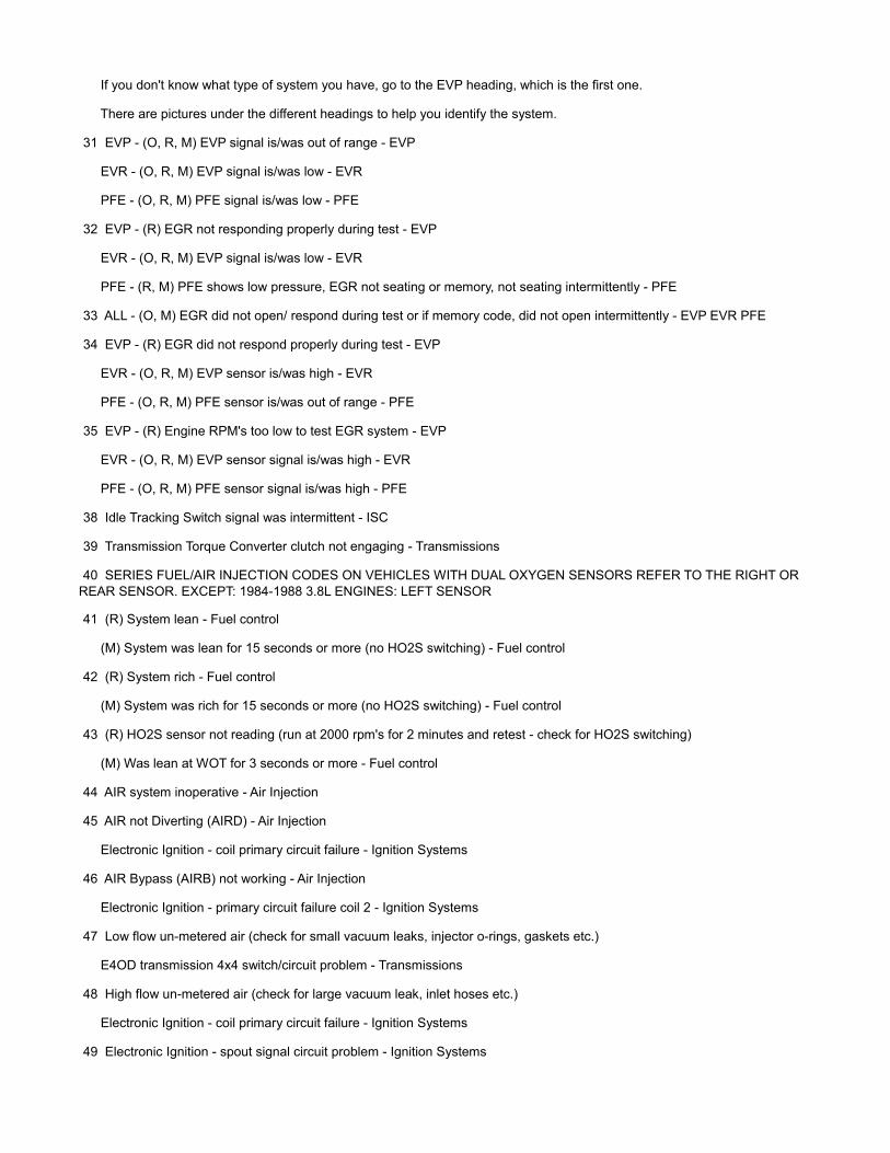
If you don't know what type of system you have, go to the EVP heading, which is the first one.
There are pictures under the different headings to help you identify the system.
31 EVP - (O, R, M) EVP signal is/was out of range - EVP
EVR - (O, R, M) EVP signal is/was low - EVR
PFE - (O, R, M) PFE signal is/was low - PFE
32 EVP - (R) EGR not responding properly during test - EVP
EVR - (O, R, M) EVP signal is/was low - EVR
PFE - (R, M) PFE shows low pressure, EGR not seating or memory, not seating intermittently - PFE
33 ALL - (O, M) EGR did not open/ respond during test or if memory code, did not open intermittently - EVP EVR PFE
34 EVP - (R) EGR did not respond properly during test - EVP
EVR - (O, R, M) EVP sensor is/was high - EVR
PFE - (O, R, M) PFE sensor is/was out of range - PFE
35 EVP - (R) Engine RPM's too low to test EGR system - EVP
EVR - (O, R, M) EVP sensor signal is/was high - EVR
PFE - (O, R, M) PFE sensor signal is/was high - PFE
38 Idle Tracking Switch signal was intermittent - ISC
39 Transmission Torque Converter clutch not engaging - Transmissions
40 SERIES FUEL/AIR INJECTION CODES ON VEHICLES WITH DUAL OXYGEN SENSORS REFER TO THE RIGHT OR REAR SENSOR. EXCEPT: 1984-1988 3.8L ENGINES: LEFT SENSOR
41 (R) System lean - Fuel control
(M) System was lean for 15 seconds or more (no HO2S switching) - Fuel control
42 (R) System rich - Fuel control
(M) System was rich for 15 seconds or more (no HO2S switching) - Fuel control
43 (R) HO2S sensor not reading (run at 2000 rpm's for 2 minutes and retest - check for HO2S switching)
(M) Was lean at WOT for 3 seconds or more - Fuel control
44 AIR system inoperative - Air Injection
45 AIR not Diverting (AIRD) - Air Injection
Electronic Ignition - coil primary circuit failure - Ignition Systems
46 AIR Bypass (AIRB) not working - Air Injection
Electronic Ignition - primary circuit failure coil 2 - Ignition Systems
47 Low flow un-metered air (check for small vacuum leaks, injector o-rings, gaskets etc.)
E4OD transmission 4x4 switch/circuit problem - Transmissions
48 High flow un-metered air (check for large vacuum leak, inlet hoses etc.)
Electronic Ignition - coil primary circuit failure - Ignition Systems
49 Electronic Ignition - spout signal circuit problem - Ignition Systems
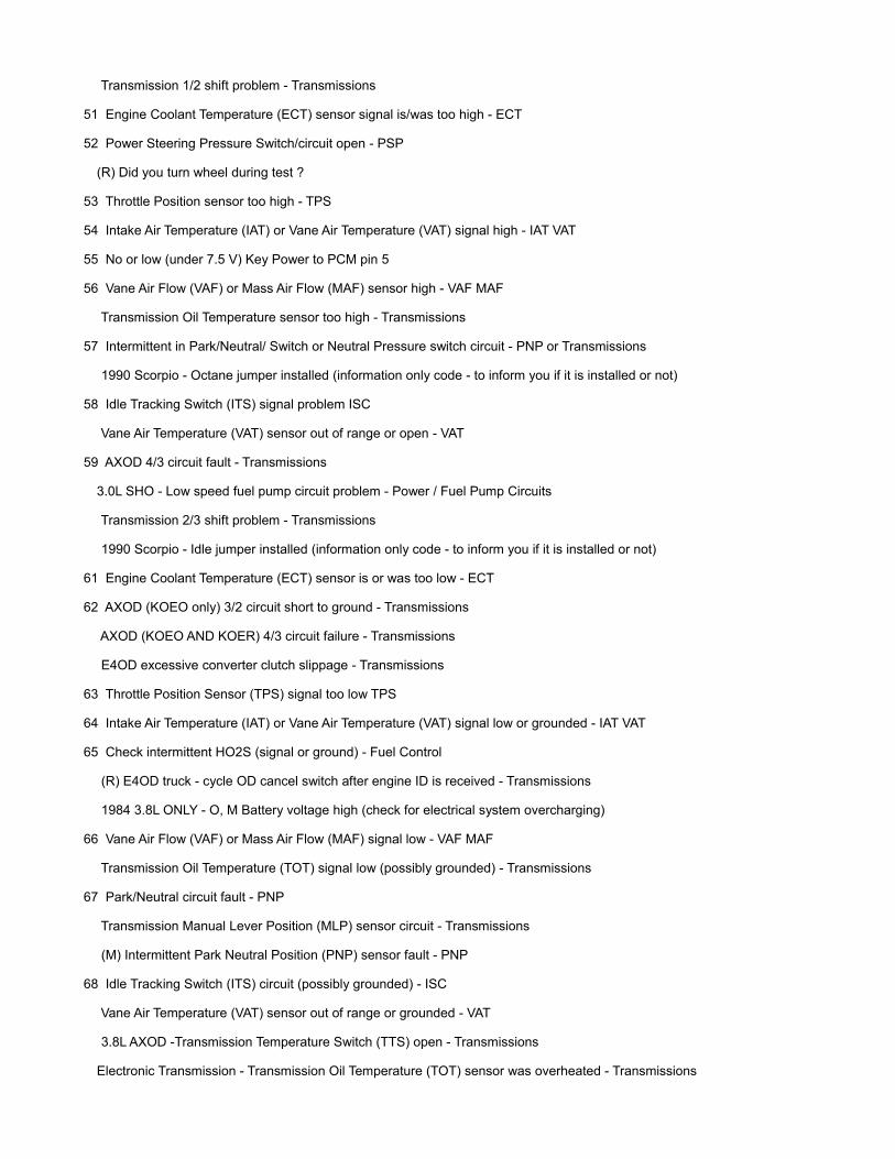
Transmission 1/2 shift problem - Transmissions
51 Engine Coolant Temperature (ECT) sensor signal is/was too high - ECT
52 Power Steering Pressure Switch/circuit open - PSP
(R) Did you turn wheel during test ?
53 Throttle Position sensor too high - TPS
54 Intake Air Temperature (IAT) or Vane Air Temperature (VAT) signal high - IAT VAT
55 No or low (under 7.5 V) Key Power to PCM pin 5
56 Vane Air Flow (VAF) or Mass Air Flow (MAF) sensor high - VAF MAF
Transmission Oil Temperature sensor too high - Transmissions
57 Intermittent in Park/Neutral/ Switch or Neutral Pressure switch circuit - PNP or Transmissions
1990 Scorpio - Octane jumper installed (information only code - to inform you if it is installed or not)
58 Idle Tracking Switch (ITS) signal problem ISC
Vane Air Temperature (VAT) sensor out of range or open - VAT
59 AXOD 4/3 circuit fault - Transmissions
3.0L SHO - Low speed fuel pump circuit problem - Power / Fuel Pump Circuits
Transmission 2/3 shift problem - Transmissions
1990 Scorpio - Idle jumper installed (information only code - to inform you if it is installed or not)
61 Engine Coolant Temperature (ECT) sensor is or was too low - ECT
62 AXOD (KOEO only) 3/2 circuit short to ground - Transmissions
AXOD (KOEO AND KOER) 4/3 circuit failure - Transmissions
E4OD excessive converter clutch slippage - Transmissions
63 Throttle Position Sensor (TPS) signal too low TPS
64 Intake Air Temperature (IAT) or Vane Air Temperature (VAT) signal low or grounded - IAT VAT
65 Check intermittent HO2S (signal or ground) - Fuel Control
(R) E4OD truck - cycle OD cancel switch after engine ID is received - Transmissions
1984 3.8L ONLY - O, M Battery voltage high (check for electrical system overcharging)
66 Vane Air Flow (VAF) or Mass Air Flow (MAF) signal low - VAF MAF
Transmission Oil Temperature (TOT) signal low (possibly grounded) - Transmissions
67 Park/Neutral circuit fault - PNP
Transmission Manual Lever Position (MLP) sensor circuit - Transmissions
(M) Intermittent Park Neutral Position (PNP) sensor fault - PNP
68 Idle Tracking Switch (ITS) circuit (possibly grounded) - ISC
Vane Air Temperature (VAT) sensor out of range or grounded - VAT
3.8L AXOD -Transmission Temperature Switch (TTS) open - Transmissions
Electronic Transmission - Transmission Oil Temperature (TOT) sensor was overheated - Transmissions
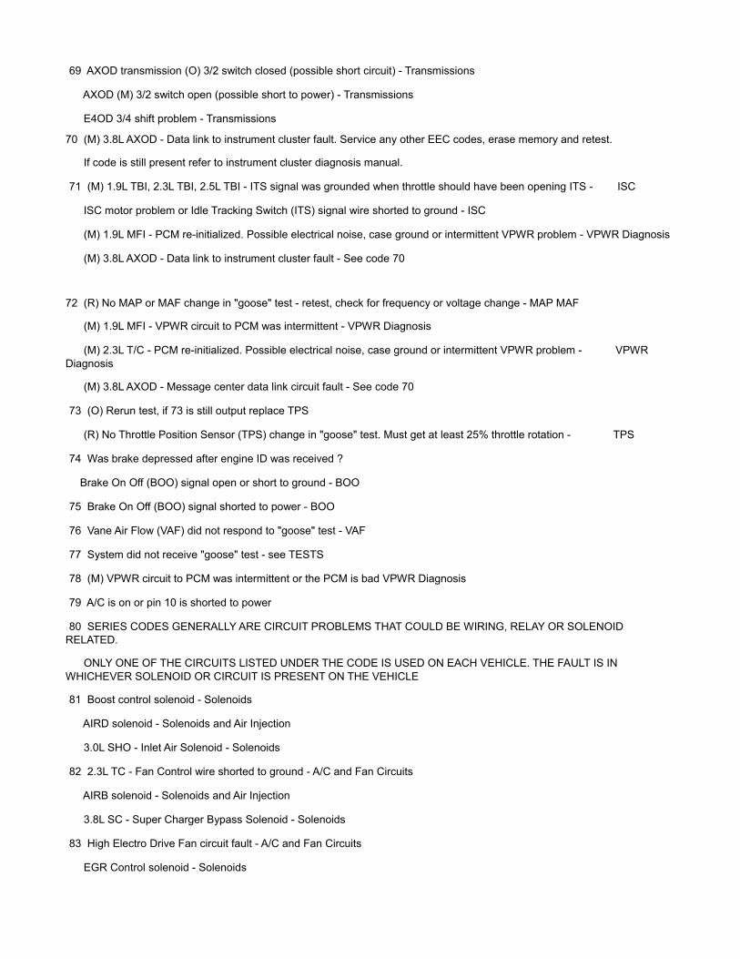
69 AXOD transmission (O) 3/2 switch closed (possible short circuit) - Transmissions
AXOD (M) 3/2 switch open (possible short to power) - Transmissions
E4OD 3/4 shift problem - Transmissions
70 (M) 3.8L AXOD - Data link to instrument cluster fault. Service any other EEC codes, erase memory and retest.
If code is still present refer to instrument cluster diagnosis manual.
71 (M) 1.9L TBI, 2.3L TBI, 2.5L TBI - ITS signal was grounded when throttle should have been opening ITS - ISC
ISC motor problem or Idle Tracking Switch (ITS) signal wire shorted to ground - ISC
(M) 1.9L MFI - PCM re-initialized. Possible electrical noise, case ground or intermittent VPWR problem - VPWR Diagnosis
(M) 3.8L AXOD - Data link to instrument cluster fault - See code 70
72 (R) No MAP or MAF change in "goose" test - retest, check for frequency or voltage change - MAP MAF
(M) 1.9L MFI - VPWR circuit to PCM was intermittent - VPWR Diagnosis
(M) 2.3L T/C - PCM re-initialized. Possible electrical noise, case ground or intermittent VPWR problem - VPWR Diagnosis
(M) 3.8L AXOD - Message center data link circuit fault - See code 70
73 (O) Rerun test, if 73 is still output replace TPS
(R) No Throttle Position Sensor (TPS) change in "goose" test. Must get at least 25% throttle rotation - TPS
74 Was brake depressed after engine ID was received ?
Brake On Off (BOO) signal open or short to ground - BOO
75 Brake On Off (BOO) signal shorted to power - BOO
76 Vane Air Flow (VAF) did not respond to "goose" test - VAF
77 System did not receive "goose" test - see TESTS
78 (M) VPWR circuit to PCM was intermittent or the PCM is bad VPWR Diagnosis
79 A/C is on or pin 10 is shorted to power
80 SERIES CODES GENERALLY ARE CIRCUIT PROBLEMS THAT COULD BE WIRING, RELAY OR SOLENOID RELATED.
ONLY ONE OF THE CIRCUITS LISTED UNDER THE CODE IS USED ON EACH VEHICLE. THE FAULT IS IN WHICHEVER SOLENOID OR CIRCUIT IS PRESENT ON THE VEHICLE
81 Boost control solenoid - Solenoids
AIRD solenoid - Solenoids and Air Injection
3.0L SHO - Inlet Air Solenoid - Solenoids
82 2.3L TC - Fan Control wire shorted to ground - A/C and Fan Circuits
AIRB solenoid - Solenoids and Air Injection
3.8L SC - Super Charger Bypass Solenoid - Solenoids
83 High Electro Drive Fan circuit fault - A/C and Fan Circuits
EGR Control solenoid - Solenoids
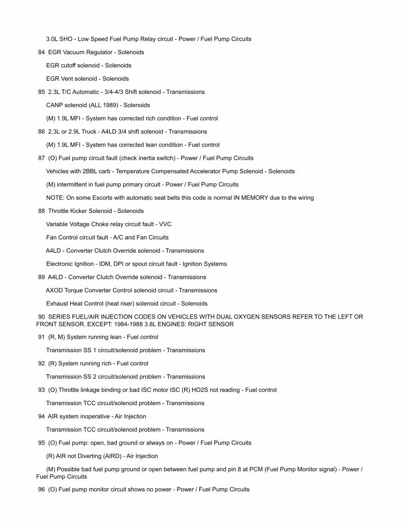
3.0L SHO - Low Speed Fuel Pump Relay circuit - Power / Fuel Pump Circuits
84 EGR Vacuum Regulator - Solenoids
EGR cutoff solenoid - Solenoids
EGR Vent solenoid - Solenoids
85 2.3L T/C Automatic - 3/4-4/3 Shift solenoid - Transmissions
CANP solenoid (ALL 1989) - Solenoids
(M) 1.9L MFI - System has corrected rich condition - Fuel control
86 2.3L or 2.9L Truck - A4LD 3/4 shift solenoid - Transmissions
(M) 1.9L MFI - System has corrected lean condition - Fuel control
87 (O) Fuel pump circuit fault (check inertia switch) - Power / Fuel Pump Circuits
Vehicles with 2BBL carb - Temperature Compensated Accelerator Pump Solenoid - Solenoids
(M) intermittent in fuel pump primary circuit - Power / Fuel Pump Circuits
NOTE: On some Escorts with automatic seat belts this code is normal IN MEMORY due to the wiring
88 Throttle Kicker Solenoid - Solenoids
Variable Voltage Choke relay circuit fault - VVC
Fan Control circuit fault - A/C and Fan Circuits
A4LD - Converter Clutch Override solenoid - Transmissions
Electronic Ignition - IDM, DPI or spout circuit fault - Ignition Systems
89 A4LD - Converter Clutch Override solenoid - Transmissions
AXOD Torque Converter Control solenoid circuit - Transmissions
Exhaust Heat Control (heat riser) solenoid circuit - Solenoids
90 SERIES FUEL/AIR INJECTION CODES ON VEHICLES WITH DUAL OXYGEN SENSORS REFER TO THE LEFT OR FRONT SENSOR. EXCEPT: 1984-1988 3.8L ENGINES: RIGHT SENSOR
91 (R, M) System running lean - Fuel control
Transmission SS 1 circuit/solenoid problem - Transmissions
92 (R) System running rich - Fuel control
Transmission SS 2 circuit/solenoid problem - Transmissions
93 (O) Throttle linkage binding or bad ISC motor ISC (R) HO2S not reading - Fuel control
Transmission TCC circuit/solenoid problem - Transmissions
94 AIR system inoperative - Air Injection
Transmission TCC circuit/solenoid problem - Transmissions
95 (O) Fuel pump: open, bad ground or always on - Power / Fuel Pump Circuits
(R) AIR not Diverting (AIRD) - Air Injection
(M) Possible bad fuel pump ground or open between fuel pump and pin 8 at PCM (Fuel Pump Monitor signal) - Power / Fuel Pump Circuits
96 (O) Fuel pump monitor circuit shows no power - Power / Fuel Pump Circuits

(R) AIR Bypass (AIRB) not working - Air Injection
(M) (Service 87 code first if present) Fuel pump relay or battery power feed was open - Power / Fuel Pump Circuits
97 E4OD OD cancel light circuit failure - Transmissions
98 (R) Did not pass KOEO yet (Get 11 in KOEO first)
Transmission EPC circuit/solenoid failure - Transmissions
99 (R) ISC needs to learn (Let idle for 2 minutes; Erase memory and retest)
Transmission EPC circuit/solenoid failure - Transmissions
Three Digit Codes: (4) 111 System checks OK
112 (O,M) Intake Air Temperature (IAT) sensor is/was low or grounded - IAT
113 (O,M) IAT sensor is/was high or open - IAT
114 (O,R) IAT sensor out of range - IAT
116 (O,R) Engine Coolant (ECT) sensor out of range - ECT
117 (O,M) ECT sensor is/was low or grounded - ECT
118 (O,M) ECT sensor is/was high or open - ECT
121 (O,R,M) Throttle Position (TP) sensor out of range - TPS
122 (O,M) TP low (possibly grounded or open circuit) - TPS
123 (O,M) TP is/was high or short to power - TPS
124 (M) TP voltage was higher than expected - Fuel control
125 (M) TP voltage was lower than expected - Fuel control
126 (O,R,M) MAP or BARO sensor out of range - ">MAP
128 (M) MAP vacuum has not been changing - check vacuum lines - ">MAP
129 (R) No MAP or Mass Air Flow sensor change during "goose" test - MAP MAF
136 (R) Oxygen sensor not switching/system lean Left or Front HO2S - Fuel control
137 (R) Oxygen sensor not switching/system rich Left or Front HO2S - Fuel control
138 (R) Fault in Cold Start Injector circuit - Fuel control
139 (M) Oxygen sensor not switching Left or Front HO2S - Fuel control
144 (M) Oxygen sensor not switching Single, Right or Rear HO2S - Fuel control
157 (R,M) Mass Air Flow signal is/was low or grounded - MAF
158 (O,R,M) MAF sensor is/was high or short to power - MAF
159 (O,R) MAF sensor is/was out of range - MAF
167 (R) No Throttle Position sensor change in "goose" test (must get at least 25% rotation) - TPS
171 (M) Oxygen sensor not switching - system was at adaptive limits - Single, Right or Rear HO2S - Fuel control
172 (R,M) Oxygen sensor not switching - system is or was lean - Single, Right or Rear HO2S - Fuel control
173 (R,M) Oxygen sensor not switching - system is or was rich - Single, Right or Rear HO2S - Fuel control
174 (M) Oxygen sensor was slow in switching Single, Right or Rear HO2S - Fuel control
175 (M) Oxygen sensor not switching - system was at adaptive limits - Left or Front HO2S - Fuel control
176 (M) Oxygen sensor not switching - system is or was lean Left or Front HO2S - Fuel control
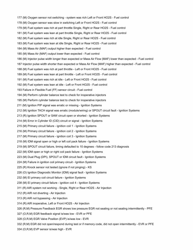
177 (M) Oxygen sensor not switching - system was rich Left or Front HO2S - Fuel control
178 (M) Oxygen sensor was slow in switching Left or Front HO2S - Fuel control
179 (M) Fuel system was rich at part throttle Single, Right or Rear HO2S - Fuel control
181 (M) Fuel system was lean at part throttle Single, Right or Rear HO2S - Fuel control
182 (M) Fuel system was rich at idle Single, Right or Rear HO2S - Fuel control
183 (M) Fuel system was lean at idle Single, Right or Rear HO2S - Fuel control
184 (M) Mass Air (MAF) output higher than expected - Fuel control
185 (M) Mass Air (MAF) output lower than expected - Fuel control
186 (M) Injector pulse width longer than expected or Mass Air Flow (MAF) lower than expected - Fuel control
187 Injector pulse width shorter than expected or Mass Air Flow (MAF) higher than expected - Fuel control
188 (M) Fuel system was rich at part throttle - Left or Front HO2S - Fuel control
189 (M) Fuel system was lean at part throttle - Left or Front HO2S - Fuel control
191 (M) Fuel system was rich at idle - Left or Front HO2S - Fuel control
192 (M) Fuel system was lean at idle - Left or Front HO2S - Fuel control
193 Failure in Flexible Fuel (FF) sensor circuit - Fuel control
194 (M) Perform cylinder balance test to check for inoperative injectors
195 (M) Perform cylinder balance test to check for inoperative injectors
211 (M) Ignition PIP signal was erratic or missing - Ignition Systems
212 (M) Ignition TACH signal was erratic (module/wiring) or SPOUT circuit fault - Ignition Systems
213 (R) Ignition SPOUT or SAW circuit open or shorted - Ignition Systems
214 (M) Error in Cylinder ID (CID) circuit or signal - Ignition Systems
215 (M) Primary circuit failure - ignition coil 1 - Ignition Systems
216 (M) Primary circuit failure - ignition coil 2 - Ignition Systems
217 (M) Primary circuit failure - ignition coil 3 - Ignition Systems
218 (M) IDM signal open or high or left coil pack failure - Ignition Systems
219 (M) SPOUT circuit failure, timing defaulted to 10 degrees - follow code 213 diagnosis
222 (M) IDM open or high or right coil pack failure - Ignition Systems
223 (M) Dual Plug (DPI), SPOUT or IDM circuit fault - Ignition Systems
224 (M) Failure in ignition coil primary circuit - Ignition Systems
225 (R) Knock sensor not tested (ignore if not pinging) - KS
226 (O) Ignition Diagnostic Monitor (IDM) signal fault - Ignition Systems
232 (M) EI primary coil circuit failure - Ignition Systems
238 (M) EI primary circuit failure - ignition coil 4 - Ignition Systems
311 (R) AIR system not working - Single, Right or Rear HO2S - Air Injection
312 (R) AIR not diverting - Air Injection
313 (R) AIR not bypassing - Air Injection
314 (R) AIR inoperative, Left or Front HO2S - Air Injection
326 (R,M) Pressure Feedback EGR shows low pressure EGR not seating or not seating intermittently - PFE
327 (O,R,M) EGR feedback signal is/was low - EVR or PFE
328 (O,R,M) EGR Valve Position (EVP) is/was low - EVR
332 (R,M) EGR did not open/respond during test or if memory code, did not open intermittently - EVR or PFE
334 (O,R,M) EVP sensor is/was high - EVR

335 (O) EGR feedback signal is/was out of range - EVR or PFE
336 (O,R,M) PFE sensor signal is/was was high - ">PFE
337 (O,R,M) EGR feedback signal is/was was high - EVR
338 (M) Cooling system did not heat up (check cooling system / thermostat operation)
339 (M) Cooling system overheated (check cooling system / thermostat operation)
341 (O) Octane jumper installed (information only code to notify you if it is installed)
411 (R) Idle speed system not controlling idle properly (generally idle too high) - ISC
412 (R) Idle speed system not controlling idle properly (generally idle too low) - ISC
452 (M) Vehicle Speed Sensor (VSS) problem
511 (O) No power to PCM pin 1 or bad PCM (processor)
512 (M) Memory power (PCM pin 1) was interrupted - Was battery disconnected ?
513 (O) Replace processor (PCM) (internal failure)
519 (O) PSP switch/circuit open - PSP
521 (R) Wheel not turned during test or PSP problem - PSP
522 (O) Park/Neutral Position (PNP) or Clutch Pedal Position (CPP) circuit fault - PNP
transmission MLP sensor out of range in park - Transmissions
524 Problem in low speed fuel pump circuit - Power / Fuel Pump Circuits
525 (O,M) Park/Neutral Position (PNP) or Clutch Pedal Position (CPP) circuit fault - PNP
528 (M) System shows voltage at pin 10 (is A/C on ?) or pin 30 (PNP, CPP switch) - PNP
529 (M) Data Communications Link to processor failure
Service any EEC codes, erase memory and retest. If code is still present refer to instrument cluster diagnosis manual.
533 (M) Data Communications Link to instrument cluster failure - see 529
536 (O,R,M) Brake On Off open or shorted to ground - BOO
538 (R) System did not receive "goose" test - TESTS
539 (O) System shows voltage at PCM pin 10. Is A/C on ?
542 (O,M) Fuel pump open, bad ground or always on - - Power / Fuel Pump Circuits
543 (O) Fuel pump monitor circuit shows no power - Power / Fuel Pump Circuits
(M) (Service 556 code first if present) Fuel pump relay or battery power feed was open - Power / Fuel Pump Circuits
551 Problem in Intake Manifold Runner Control (IMRC) solenoid/circuit - Solenoids
552 (O) AIRB solenoid/circuit failure - Solenoids
553 (O) AIRD solenoid/circuit failure - Solenoids
554 (O) Fuel Press Regulator Control solenoid/circuit fault - Power / Fuel Pump Circuits
556 (O,M) Fuel pump relay primary circuit fault - Power / Fuel Pump Circuits
557 (O,M) Low speed pump relay primary circuit fault - Power / Fuel Pump Circuits
558 (O) EGR vacuum regulator solenoid/circuit failure - EVR or PFE or Solenoids
559 (O) A/C relay primary circuit fault - A/C and Fan Circuits
563 (O) High Fan Control (HFC) circuit failure - A/C and Fan Circuits
564 (O) Fan Control (FC) circuit failure - A/C and Fan Circuits
565 (O) Canister Purge 1 solenoid/circuit failure - Solenoids
566 (O) transmission 3/4 shift solenoid/circuit - Transmissions
569 (O) Canister Purge 2 solenoid/circuit failure - Solenoids
578 (M) A/C pressure sensor VREF short to ground - A/C and Fan Circuits

579 (M) ACP sensor did not change with A/C on - A/C and Fan Circuits
581 (M) Cooling fan current was excessive - A/C and Fan Circuits
582 (O) Open cooling fan circuit - A/C and Fan Circuits
583 (M) Fuel pump current was excessive - Power / Fuel Pump Circuits
584 (M) Open power ground circuit - Power / Fuel Pump Circuits
585 (M) A/C clutch current was excessive - A/C and Fan Circuits
586 (M) Open circuit in A/C clutch - A/C and Fan Circuits
587 (O, M) Communication problem between PCM and Variable Control Relay Module (VCRM) - Power / Fuel Pump Circuits
617 (M) Transmission shift failure (1/2 shift) - Transmissions
618 (M) Transmission shift failure (2/3 shift) - Transmissions
619 (M) Transmission shift failure (3/4 shift) - Transmissions
621 (O) Solenoid/circuit failure - shift solenoid 1 - Transmissions
622 (O) Solenoid/circuit failure - shift solenoid 2 - Transmissions
624 (O,M) Solenoid/circuit failure -Electronic Pressure Control (EPC) current is high - Transmissions
625 (O,M) Solenoid/circuit failure - Electronic Pressure Control (EPC) current is low - Transmissions
626 (O) Transmission Coast Clutch (CCS) Solenoid/circuit fault - Transmissions
627 (O) Torque Converter Clutch circuit fault - Transmissions
628 (M) Excessive converter clutch slippage - Transmissions
629 (O,M) Torque Converter Clutch circuit fault - Transmissions
631 (O) Overdrive Cancel Light circuit problem - Transmissions
632 (R) E4OD - Transmission Control Switch (TCS) should be cycled once between engine ID and Goose test
633 (O) 4x4L switch should be in 4x2 or 4x4 high for the test
634 (O,M) Park/Neutral Position (PNP) or Clutch Pedal Position (CPP) circuit fault
Electronic shift transmission - Manual Lever Position (MLP) sensor out of range in PARK - Transmissions
636 (O,R) Transmission Oil Temperature (TOT) sensor out of range - Transmissions
637 (O,M) TOT sensor is/was high or open - Transmissions
638 (O,M) TOT sensor is/was low or grounded - Transmissions
639 (R,M) Transmission Speed sensor (TSS) circuit fault - Transmissions
641 (O) Transmission solenoid/circuit failure Shift Solenoid 3 - Transmissions
643 (O)(M) Torque Converter Clutch (TCC) circuit - Transmissions
645 (M) Transmission 1st gear failure - Transmissions
646 (M) Transmission 2nd gear failure - Transmissions
647 (M) Transmission 3rd gear failure - Transmissions
648 (M) Transmission 4th gear failure - Transmissions
649 (M) Transmission EPC system failure - Transmissions
651 (M) Transmission EPC solenoid/circuit fault - Transmissions
652 (O) Torque Converter Clutch (TCC) circuit fault - Transmissions
654 (O) Transmission selector not in PARK - Transmissions
656 (M) Torque Converter Clutch (TCC) slip - Transmissions
657 (M) Transmission temperature was excessive - Transmissions
998 (R) Did not pass Key On Engine Off test yet (Get 111 in KOEO first)

Abbreviations & Definitions: (5)
ACT: Air Charge temperature sensor. Senses the temperature of air entering the engine.BP: Barometric Pressure (see MAP)EEC: Electronic Engine Control Ford’s Engine management systems.ECT: Engine Coolant Temperature Sensor. Senses the coolant temperature.EGR: Exhaust Gas Re-circulation Valve. Allows some harmful exhaust gasses to be re-burned through the engine for emissions purposes.EVP: EGR Valve Position sensor.FPR: Fuel Pressure Regulator. A vacuum actuated device to keep constant fuel pressure.HEGO: Heated Exhaust Gas Oxygen sensor (O2 sensor, EGO, oxygen sensor). Detects how much oxygen is in the exhaust to determine rich or lean running conditions.IAC/ISC: Idle Air Control (Idle Speed Control) motor. An electric valve which allows air to enter the intake at idle, changing the idle speed.IAT: Intake Air Temperature (see ACT)KS: Knock Sensor. Detects Engine Knock (vibration) to allow computer to adjust timing accordinglyKOEO (O): Key On, Engine Off. Type of diagnostics test.KOER (R): Key On, Engine Running. Type of diagnostics test.MAF: Mass Air Flow SensorMAP: Manifold Absolute Pressure sensor.MIL: Malfunction Indication Lamp (Check Engine Light on Dash)MLP: Manual Lever Position.OBD: On Board Diagnostics (the computer’s diagnostics system)PCM: Power train Control Module (the computer)PIP: Computer Input for Timing Indication.PNP: Park/Neutral Position Sensor. Senses if an automatic is in park, or a standard is in neutral. Also referred to as a Neutral Safety Switch.SPOUT: Spark Output. It is a distributor to allow manual control for ignition timing. It is also the output signal of the distributor to the PCM.TFI: Thick Film Ignition. A Ford Ignition module, which is found at the base of the distributor.
TP (TPS): Throttle Position Sensor. Tells the PCM how much gas should be entering the Engine.VSS: Vehicle Speed Sensor.
TPS Calibration: (6)
Warm the engine up. Shut engine off, and turn ignition on. With a voltmeter on the appropriate setting, probe the TPS center wire with the (+) probe, and ground the (-) probe. Adjust the throttle plate adjustment screw so the voltmeter’s reading is 0.9 to 1.0V DC.
Base Idle Adjustment: (7)
This essentially is an alternate test for the TPS Calibration. The base idle is computer controlled via the Idle Air Control (IAC) motor. To do this crude base adjustment, warm the engine up. Unplug the IAC electrical connector. Restart the engine (if it doesn’t start, screw the throttle plate adjustment screw in, until it starts). Once the vehicle is running, adjust the throttle plate adjustment screw until the idle reaches 650RPM. Plug the IAC electrical connector, and restart the engine. The idle should settle to 850-950RPM. Note that it is best to use an accurate tune up tachometer, not the stock gauge.
Oxygen Sensor Testing: (8)
There may be three wires on the O2 sensor; two gray wires and one black. The black should read ground. One gray wire should read 12V with the ignition on, and the other gray wire is the one we are after. Probe this wire with the engine warm, and running with a voltmeter’s (+) probe, and ground the negative probe. While the vehicle is running, the reading should be approximately 0.5V. A reading below this indicates a lean air fuel mixture; a reading above this indicates a rich mixture. If no reading is present, and all connections are good, the sensor is probably in need of replacement.
TFI Module Resistance Test: (9)
The TFI module may be removed, and tested for resistance between terminals to determine complete failure. Often stock TFI modules only partially fail when engine temperatures get warm, and the vehicle runs rough then dies. The vehicle then restarts, and runs for 20 seconds then dies again. This is a defect, which affected ALL TFI
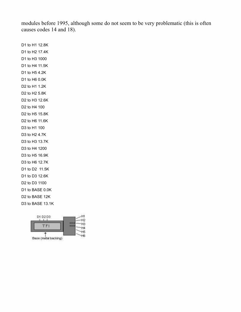
modules before 1995, although some do not seem to be very problematic (this is often causes codes 14 and 18). D1 to H1 12.8K
D1 to H2 17.4K
D1 to H3 1000
D1 to H4 11.5K
D1 to H5 4.2K
D1 to H6 0.0K
D2 to H1 1.2K
D2 to H2 5.8K
D2 to H3 12.6K
D2 to H4 100
D2 to H5 15.8K
D2 to H6 11.6K
D3 to H1 100
D3 to H2 4.7K
D3 to H3 13.7K
D3 to H4 1200
D3 to H5 16.9K
D3 to H6 12.7K
D1 to D2 11.5K
D1 to D3 12.6K
D2 to D3 1100
D1 to BASE 0.0K
D2 to BASE 12K
D3 to BASE 13.1K
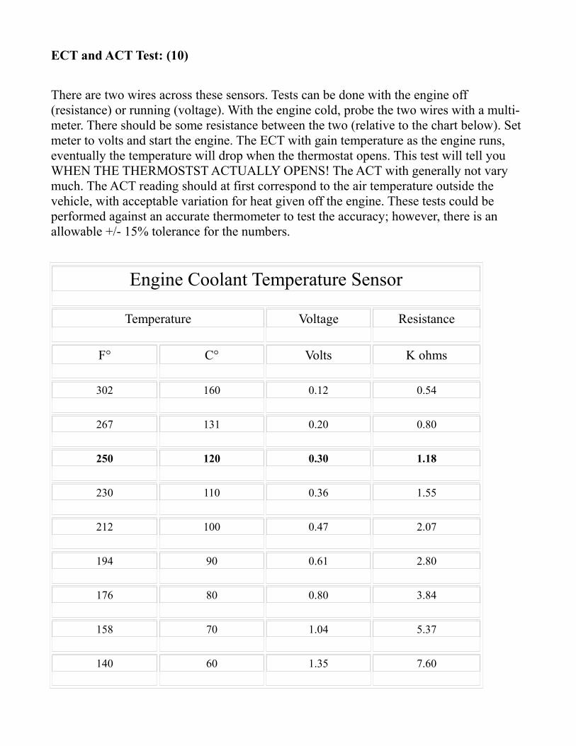
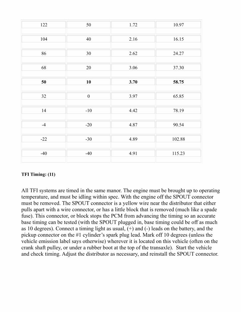
ECT and ACT Test: (10)
There are two wires across these sensors. Tests can be done with the engine off (resistance) or running (voltage). With the engine cold, probe the two wires with a multi-meter. There should be some resistance between the two (relative to the chart below). Set meter to volts and start the engine. The ECT with gain temperature as the engine runs, eventually the temperature will drop when the thermostat opens. This test will tell you WHEN THE THERMOSTST ACTUALLY OPENS! The ACT with generally not vary much. The ACT reading should at first correspond to the air temperature outside the vehicle, with acceptable variation for heat given off the engine. These tests could be performed against an accurate thermometer to test the accuracy; however, there is an allowable +/- 15% tolerance for the numbers.
Engine Coolant Temperature Sensor
Temperature Voltage Resistance
F° C° Volts K ohms
302 160 0.12 0.54
267 131 0.20 0.80
250 120 0.30 1.18
230 110 0.36 1.55
212 100 0.47 2.07
194 90 0.61 2.80
176 80 0.80 3.84
158 70 1.04 5.37
140 60 1.35 7.60
122 50 1.72 10.97
104 40 2.16 16.15
86 30 2.62 24.27
68 20 3.06 37.30
50 10 3.70 58.75
32 0 3.97 65.85
14 -10 4.42 78.19
-4 -20 4.87 90.54
-22 -30 4.89 102.88
-40 -40 4.91 115.23
TFI Timing: (11)
All TFI systems are timed in the same manor. The engine must be brought up to operating temperature, and must be idling within spec. With the engine off the SPOUT connector must be removed. The SPOUT connector is a yellow wire near the distributor that either pulls apart with a wire connector, or has a little block that is removed (much like a spade fuse). This connector, or block stops the PCM from advancing the timing so an accurate base timing can be tested (with the SPOUT plugged in, base timing could be off as much as 10 degrees). Connect a timing light as usual, (+) and (-) leads on the battery, and the pickup connector on the #1 cylinder’s spark plug lead. Mark off 10 degrees (unless the vehicle emission label says otherwise) wherever it is located on this vehicle (often on the crank shaft pulley, or under a rubber boot at the top of the transaxle). Start the vehicle and check timing. Adjust the distributor as necessary, and reinstall the SPOUT connector.

IAC Cleaning/Testing: (12)
The IAC is usually a cylindrical unit attached to the upper intake manifold. This unit electrically controlled by the computer, and allows air to flow into the intake at idle, bypassing the throttle plate. The extra air is accompanied by extra fuel to bring the idle up to proper speed, and when cold, allows a high idle condition. These units may become dirty, and need cleaning. Many idle and stalling issues tend to be blamed on these units. Cleaning is achieved by removing the electrical connector, and two screws holding it on. Once off of the vehicle, clean with throttle body cleaner (or a good carburetor cleaner). Continue cleaning until unit is clean, like new; reinstall unit. This is also a good time to clean the intake, and EGR ports (if applicable). Testing may be achieved by bringing the engine to operating temperature, noting the idle speed (should be within spec). Unplug the unit’s electrical connector, and the idle should drop to about 650 RPM. When the unit is reinstalled, it should return to normal idle speed. If the vehicle does not idle at proper RPM (too low), there are no vacuum leaks, and the TPS calibration is correct, than the unit is most likely faulty.
FPR Testing: (13)
An essential part of the EEC-IV system is the fuel system. Often, the fuel system is blamed for faults which actually occur elsewhere; however, a simple test can test many components. A high pressure fuel tester must be connected to the fuel relief valve on the fuel rail (usually a Schrader valve). First relieve fuel system pressure, then attach the tester. Next, turn the key on (engine off) to prime the fuel system. There should be 36-42PSI of pressure. Start the engine. The pressure at idle should remain within the same range. Rev the engine a few times to ensure fuel pressure remains constant. Excess pressure usually determines a faulty FPR. Too little pressure could be the FPR, fuel filter, fuel pumps, or a leak.
Knock Sensor: (14)
The knock sensor is a device used to detect engine pinging (vibrations) so that the computer can advance or retard riming for optimal performance. Because the knock sensor is sensitive to vibrations, it must be tightened to proper torque, and not have anything vibrating against it. Additionally it has an insulation that must remain in good shape. Generally if the engine code detects the KS, the sensor is usually bad unless a visual or electrical inspection proves otherwise.

MAP Testing: (15)
Speed density computers use a MAP sensor (other usually use a MAF). The MAP sensor measures Barometric Pressure (BP) when the key is first turned (this accommodates for altitude). When the engine is running it takes the BP and subtracts the pressure caused by the engine (pistons) to send a frequency (in Hz) to the computer. Testing requires two tools: a vacuum pump (with gauge) a 5V DC supply and a Digital multi-meter with a frequency (Hz) setting. There are three electrical connectors on the sensor. The one closest to the Vacuum lines is input from the computer, the middle wire is signal output to the computer, and the wire furthest from the vacuum line is the ground line (which grounds through the computer). To test the unit, it must be removed from the vehicle, have vacuum applied to it, than measure the frequency across the ground and signal (middle) wires, as per the chart below while 5V DC is applied to the input wire (closest to the vacuum line). The list below is +/- 3Hz.
in-Hg kPa Hz
0 0 159
3 10.2 150
6 20.3 141
9 30.5 133
12 40.6 125
15 50.8 117
18 61.0 109
21 71.1 102
24 81.3 95
27 91.5 88
30 101.6 80

BroncoII Leak Prone AreasFind the Leak Before It's Too Late!
This is for those who are looking into getting a Bronco II for a good daily driver, of for those who already have one, but can't figure out where the leak is coming from.
Here are the most common places for a BII to leak. Some of them can be fixed fairly easy, some are a major pain in the butt. I'll do my best to describe ways to fix them, but in most cases you'll probably want to take it to a body shop for long-lasting fix.
1: Cowl vent.This is mainly a problem on the first-generation (84-88) bronco II. Leaves and other debris will clog the drain vents and will cause moisture to sit and create rust holes. Symptoms: Wet front carpet, water in glove box. If caught in time, it is possible to remove the access covers under the hood and spread seam-sealer in the holes, but if its a fairly large hole, the fenders have to come off, the cowl panel has to be removed (lots of spot-weld drilling) and the rusted metal has to be replaced. I should mention this isn't as much of a problem on later (89-90) bronco II's because the cowl was changed from slots to a "mesh" pattern to prevent most debris from entering.
2: A-pillar/roof joint/drip-rail.This is a VERY common leak on BII's no matter the year. The seam sealer gets brittle with age and either cracks or crumbles away leaving an open seam. It can also be hidden behind the windshield trim. Symptoms are wet floorboard and a drip from the headliner just past the windshield. A temp fix is to smear silicone down in the cracks and joints with your finger. This will stop the leak for a little while until the rest of the seam sealer cracks. Best fix is to dig all of the old seam-sealer out and put new sealer in.
3: Side-glass seals.These are usually easier to spot as most of the time the leak will run down the inside of the glass when it rains. Symptoms are wet cargo-carpet and streaks on the inside of a foggy window. The fix is pretty simple, just time consuming. Basically you have to remove all of the interior trim for that side of the truck, un-bolt the glass, and with an assistant work a screw diver under the glass enough to run a piece of piano wire or some wire thin enough to cut what's left of the seal. DO NOT try to force the glass out or else you will shatter the glass, end up with cuts, have a nice open hole in your BII, and have to drop a good chunk of money for a replacement (and they're not cheap.)
After the glass is out, clean the sealing surfaces as best as you can, and apply some "tar ribbon" around the sealing surface of the glass. You can get the tar ribbon at just about any automotive store or windshield shop. Everything else is reverse of removal.

4: Rear drip rail.Why ford put these on is beyond me, but they too can cause leaks. Basically the same was as number 2. Seam sealer dries, cracks, leaks. Symptoms are wet cargo carpet. The fix is the same as number 2's.
5: Area behind top of rear hatch.Once again, seam sealer is the problem, but this time there is a bunch of it. symptoms are wet rear headliner and wet cargo carpet. There really isn't a good temp fix for this because there is so much seam sealer that you'll spend more time smearing silicone over it than it would take to break all of the seam sealer out and replace it.
All of the leaks above can lead to rust that puts the strength of the body in question. Rust around the front and rear body to frame bolts can be a problem, especially in a collision. The best way to fix it is to catch it before it starts.
Hopefully this will help you folks out and keep you from making the same mistakes as me.
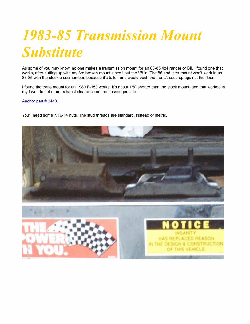
1983-85 Transmission Mount Substitute
As some of you may know, no one makes a transmission mount for an 83-85 4x4 ranger or BII. I found one that works, after putting up with my 3rd broken mount since I put the V8 in. The 86 and later mount won't work in an 83-85 with the stock crossmember, because it's taller, and would push the trans/t-case up against the floor.
I found the trans mount for an 1980 F-150 works. It's about 1/8" shorter than the stock mount, and that worked in my favor, to get more exhaust clearance on the passenger side.
Anchor part # 2448.
You'll need some 7/16-14 nuts. The stud threads are standard, instead of metric.

Better Power Steering Pump
The pump on mine is getting noisy and steering is getting harder, so as my habit is I thought "as long as I'm fixing I might as well improve." Looking into it I found Ford used a Saginaw pump on late 70s full size pickups; NAPA part number NSP 20-6244. I've pulled one out of the box and done the measurements and it all matches up.
Rubber Body Mount Replacement and Body Lift Installation
Foreword:
When installing a body lift, it is strongly recommended that you replace the rubber body mounts with aftermarket polyurethane bushings. On a stockvehicle, when a 2" lift is being installed, a steering extension may not be needed; others will require it. Mitsubishi transmissions (FM 145, and FM 146) will not need any modifications for the shifter; Mazda transmissions will need an extension to be purchased. The fan shroud will need to be removed and modified. The parking brake cable under the driver’s side floorboard may get stretched, so a relocation of its bracket may be necessary. All other stock parts should accept the 2 and 3" lifts.
There are 10 mounts in total (5 per side). The front 2 beside the radiator support, the next two under the front floor boards, the next pair under the rear passenger’s floor board, and the remaining four are accessed by removing the gas tank. All stock mounts are held with a nut and bolt, and the top and bottom mounts are pressed together, except for the front two. The front mounts have an inverted nut and bolt, and are threaded together, rather than pressed together.
When doing this procedure, the most time consuming part is removing the old mounts. The easiest way to do so is to break the bolt by loosening/tightening the bolt head with a cheater bar until the bolt snaps, and falls through, than the mount can be cut at the bottom side of the upper bushing with a reciprocating saw (this is essentially the easiest method, and will work even if the bolts will not come out).
Before starting, take proper safety precautions. Block the wheels. When jacking the body, always use a piece of wood between the jack and the body to prevent damage. Disconnect the battery (-) terminal. When raising the body keep a close eye on anything that could be stretched.
Procedure:A. Locating all the bolts.
The front bolts are to the sides of the radiator mounts (see photo 2). Nothing has to be removed for their access. Removing the seats most easily accesses the 4 bolts below the floorboards. 4 bolts attach each seat. The seat belt buckle will have to slide off of its track in order to fully remove the seat (and don’t forget the buzzer electrical connection on the driver’s side). Now remove the doorsill plates, and the front kick panels. Lifting the carpet up will reveal two oval shaped covers on each side, which are held in place with 2 screws (see photo 1). Removal of these exposes the body mounts bolt heads. Access of the nuts is easy; however, on the driver’s side, partial removal of the parking brake cable may be necessary (see photo 6).
Removing the lift gate sill plate can access the rear bolts, and lifting up the cargo area’s carpet. This exposes 2 bolt heads at the rear, and 2 rectangular covers towards the front. The nuts for these bolts require the removal of the gas tank.
The gas tank skid plate bolts are accessed by removing the plastic trim that sits at the top of the bumper. The rear bolts for the skid plate are located through access holes in the bottom of the bumper, and the nuts from the newly exposed area above. The front two bolts and nuts are located above and behind the pumpkin. Unscrew the three bolts holding the gas tank filler neck to the body, and remove the gas cap. Now the gas tank can be supported with a jack and piece of wood. Remove the two bolts securing the tank’s straps (located near the front bolts for the skid plate). The tank should be lowered just enough to remove the connections (fuel lines, electrical,
and vent line). Then the tank can be gently lowered and removed. Now the 4 nuts and body mounts are exposed (see photo 4).
B. Removal of the bolts.
Using a large breaker bar, and a wrench on the bolts, try to snap the bolts off, otherwise remove the nuts with the cheater bar or impact gun. If a bolt will not snap, or come loose, leave it at this point; however, breaking the bolt is the best method. Once all the bolts are removed, place them back in their holes, to keep the body aligned on the frame. Remember that the stock upper and lower mounts are joined together (see photo 5).
C. Preparing For Lift.
Have all proper parts neatly laid out, and ensure you are using new nuts, bolts and washers. Undo the two bolts on top of the fan shroud, and pop the shroud out of place. On the steering shaft under the hood, loosen the bolt the attached the upper and lower shafts. It is highly recommended that the parking brake cable be disconnected on the driver’s side to prevent over stretching (see photo 6).
D. Installing mounts, and lifts.
Working on one side of the vehicle at a time only, jack up the body enough so that the new mounts and lift can be put in place. Remove the bolts for the mounts you are working on. Remove the old mounts by cutting through the bottom side of the upper mount with the reciprocating saw, unless the old mounts came apart when breaking the nuts off. Note that the front pair of mounts may be easier to remove by unscrewing one from the other. Now put the proper body mounts, lift, bolt, and washers in place, but do not add the nut. Continue with all mounts on the truck. Now that everything is in place, double check the alignment of the body on the frame by measuring any reference points. Once satisfied, the nuts can be installed, and tightened. Tighten until the upper body mount just starts to get squished (or to a torque spec provided). Don’t forget to us loctite on the nuts.
E. Finish Steps.
Installation of all items is the reverse of removal, with the exception of the following procedures:
i. Install steering extension if there is not enough play on the stock steering shaft by gently forcing the extension up the trucks steering shaft, and bolting back in place (photos 8, 9, 10).
ii. Reinstall parking brake cable. If it binds due to the angle, grind off the parking brake bracket (below the drivers door) and reinstall 1" higher on the frame.
iii. The lift gate sill plate will not go back into place, and a new piece will have to be made to fix the gap (photo 11). Or the Bumper can be removed, and repositioned 2-2 ½" up the frame, while reusing the stock sill plate.
Conclusion:After the vehicle has been finished, double check for anything else that may be stretched. Check for binding in the steering shaft, and check the operation of the parking brake. Drive the vehicle for 500km (250-300 miles) and note any problems or clunks; retighten the mounts if necessary.
(Picture 1)
(Picture 2)
(Picture 3)

(Picture 4)
(Picture 5)
(Picture 6)

(Picture 7)
(Picture 8)
(Picture 9)

(Picture 10)
(Picture 11)
Exhaust Info
Many people decide to modify their stock exhaust on their Bronco IIs. Typically the reason is for either sound or better performance, maybe even both. The sound achieved is subjective, and what sounds good to one person may not sound good to another (eg: import sound versus V8 sports car verses diesel). Performance can be a tricky thing. If done improperly, performance can be hurt or modified in an undesirable way.The Law:There are motor vehicle laws governing exhausts, these vary between juristictions, but generally are similar. The laws address noise and typically address a certain degree (in decibels) to be the maximum tolerable noise, with this law there must be some kind of muffler on the vehicle: thus it is illegal not to have a muffler. The laws also address catalytic converters. It is illegal to remove a catalytic converter and not replace it, sometimes you may even be fined and jailed for doing such. Some laws state that only vehicles less than 10 years old need catalytic converters, others suggest that if it came with one at the factory it must always have one. Other laws address where the exhaust exits. Typically the exhaust has to exit away from all passengers (behind the drivers door), and must point horizontal or down. Exhausts tips may not exit in an upward position. Also, it is usually illegal to add any device that makes the exhaust louder (like the tips you often see on imports). Check local laws before modifying your exhaust.The parts:The exhaust manifold is the part that bolts to the engine. It is generally large and heavy. The purpose for this is to minimize the noise emitted by the exhaust. Few vehicles came with headers. Headers are basically thin tubes welded to a flange that bolts to the engine. The purpose of a header is to allow better cooling than a manifold, but because headers have less metal to insulate noise, they create a louder exhaust. Headers are also much easier to make than manifolds, since manifolds require casting, where as headers can be produced by welding and bending tubes. A header that is modified correctly can be made to make more power, and can help lower or higher end power band. Headers are commonly avaliable aftermarket in varying degrees of quality.Collector pipes are associated with headers. It is the pipe that attaches to the end of the header so the header can be mated to the round exhaust pipes. Typically on vehicles with manifolds there will be either just the exhaust tube connected to the manifold, or a Y-pipe style used on some V shaped engines. The Y pipe is designed to connect the exhaust from the left and right manifolds into one single round exhaust pipe. There are many variations of the Y pipe including H shaped pipes. A Y pipe may be used with some headers.

The catalytic converter is a very important part for emission purposes. Essentially a catalytic converter is filled with special metals that react with toxins leaving the engine "catalyzing" with them to create less harmful gasses or liquids. Stock catalytic converters are made of stainless steel and tend to last a long time. If needing a replacement look very carefully. Many aftermarket catalytic converters do NOT flow as well as stock (even some of the cheaper "high flow" ones are actually more restrictive). Also, many aftermarket units are less emission friendly than stock. Stock converters are subject to harsh government testing for quality, longevity, and emission control, aftermarket units are NOT, so choose wisely. A good high end aftermarket unit, however, may be better than stock, but you will pay. Chances are if there is a "high flow" aftermarket unit that costs a lot less than a stock one, it probably isn't worth your money. Additionally, there are several types of converters. I will clasify them in 2 categories though: normal (newer style), and air injection models (older units). Older units required air to be pumped into the convertor via an airpump. The air pump was typically was a pump driven by the accessory pullies (like an air conditioning pump). These old units tend to be very restrictive and get very hot. If your vehicle has one, you will need to find a catalytic converter that has an air inlet, or switch to a newer style unit and get rid of the air pump.Mufflers tend to be the most discussed part of the exhaust system. There are more mufflers avaliable than any other part of the exhaust system, and the muffler is a crutial controller for the overall sound. Prices range from cheap (about $15 and up to several hundred dollars). Important things to look for are metal material and thickness. Cheap mufflers tend to use a cheap steel or aluminized steel that often rusts out quickly, typically in the thinner units. A very good muffler would be made of stainless steel. Also note the construction: is it pressed together, or welded at the seams? Welding is the better method. Essentially there are 2 types of mufflers: restrictive, and free flowing. Restrictive mufflers tend to have metal inside the muffler in a varied way (tubes, tunnels, channels, etc). Free flowing tend to have little in there. Free flowing tend to be inexpensive, and give a very loud pungent, un-precise noise, a typical example is the glass pack (or cherry bomb) muffler. The restrictive units tend to be more expensive. It is a myth that free glowing makes more sound and power than a restrictive muffler. A good, well tuned restrictive muffler may flow as much, and be about as loud as a free flowing muffler while giving a deeper more throaty tone, but it all depends on the quality. Weather or not a muffler is too restrictive is dependant on many characteristics, but mainly how much the engine flows. If the engine sucks in so much air, the muffler should allow that air to exit fairly easily. On most smaller engines (4 cylinders, v6s, and small block V8s, flow is not an issue as the mufflers tend to be effeceint enough to handle them).Exhaust tubing. Well you have to connect all the exhaust components together with tubes. If replacing the stock exhaust, the tubes may be purchased pre bent and cut to factory specifications. If making your own custom exhaust you will need to bend and cut the tubes yourself. Many exhaust shops are happy to do this part for you as they have the proper equipment to do it right. But you still have to choose the size and metal to use. For best performance use the same size tube as stock, or NO more than 2 sizes larger. On the

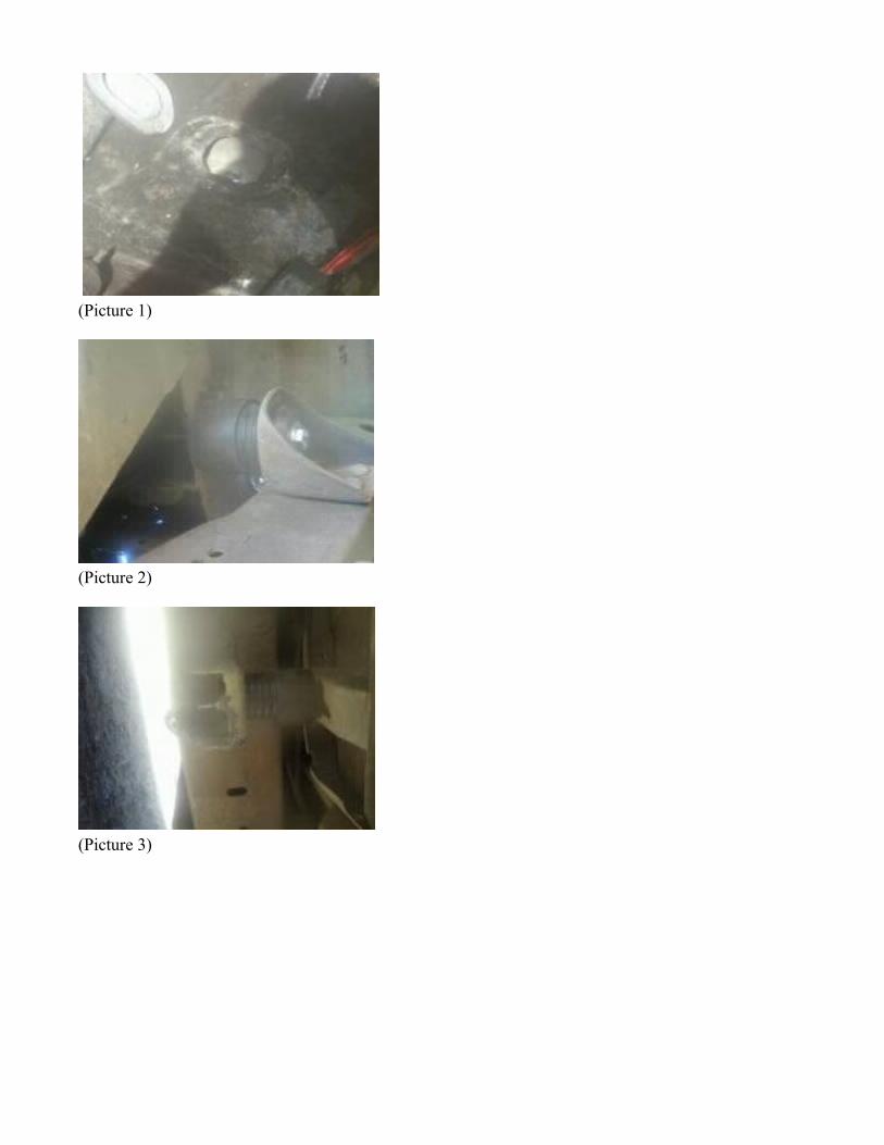
Bronco IIs, 1 7/8" 2" or 2 1/4" tends to be best. Quality in pipes depends on the thickness and material used. Thicker tubes last longer, but can be very hard to bend. Stainless steel will last longer than regular steel, but is extremely costly. You also have to consider where the exhaust will be mounted so that the pipes and other components will be out of the way of the trucks moving parts (axles, drive-shafts, springs, etc). And also far away from anything flamable. You also have to consider where to put the exhaust hangers that will mount the exhaust to the frame of the vehicle.Putting It all Together:You will need to start with a header or using the stock manifolds. If using a header, there are some products avaliable in the aftermarket. The main things are weather it is 2wd or 4wd. On Bronco IIs there is little room for the drivers side header to exit by the bell housing since the steering linkage, starter, radius arm end, and front driveshaft (on 4wd) are all there. On 4wd vehicles, the driver side exhaust (from the headers collector) will have to be routed under the bell housing to the passanger's side because the front driveshaft would be in the way (on 2wd this is not an issue). Now you decide weather or not to cross the two sides over. I reccomend this. Crossover can be achieved with the stock style Y or H pipe, with an x pipe, a crossover pipe, or simply by running the tubes into one dual input muffler. But before we discuss mufflers we have to mount the oxygen sensor at (or slightly behind) the crossover. The oxygen sensor must be as near the engine as possible since it only operates properly at tempertatures above 600 degrees farenheit; for this reason your crossover should be near the front of the vehicle as well. After the oxygen sensor we can place whichever catalytic converter you chose. Then your choice of muffler and tail pipes. The exhaust may exit the sides or out the back, your choice.This is a typical stock Bronco II exhaust (some may have a split/dual catalytic converter, and may have a resonator towards the rear axle).

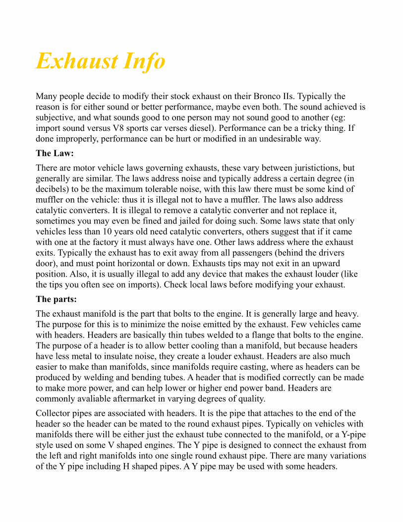
This next set up is probably the best modified version. It is completley legal, best for performance, very good for sound and works with appropriate headers on 2wd and 4wd trucks.
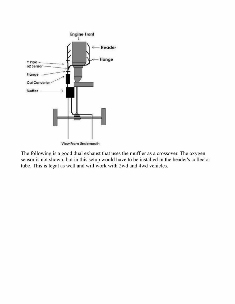
The following is a good dual exhaust that uses the muffler as a crossover. The oxygen sensor is not shown, but in this setup would have to be installed in the header's collector tube. This is legal as well and will work with 2wd and 4wd vehicles.

This next setup is a classic style dual exhaust using an "X" pipe as a crossover. It would typically be used on a muscle car. The mufflers may be placed anywhere in the rear. It does not leave appropriate space for a catalytic converter (which would have to mount towards the transmission). It is not good for 4wd since the exhaust will hang low.
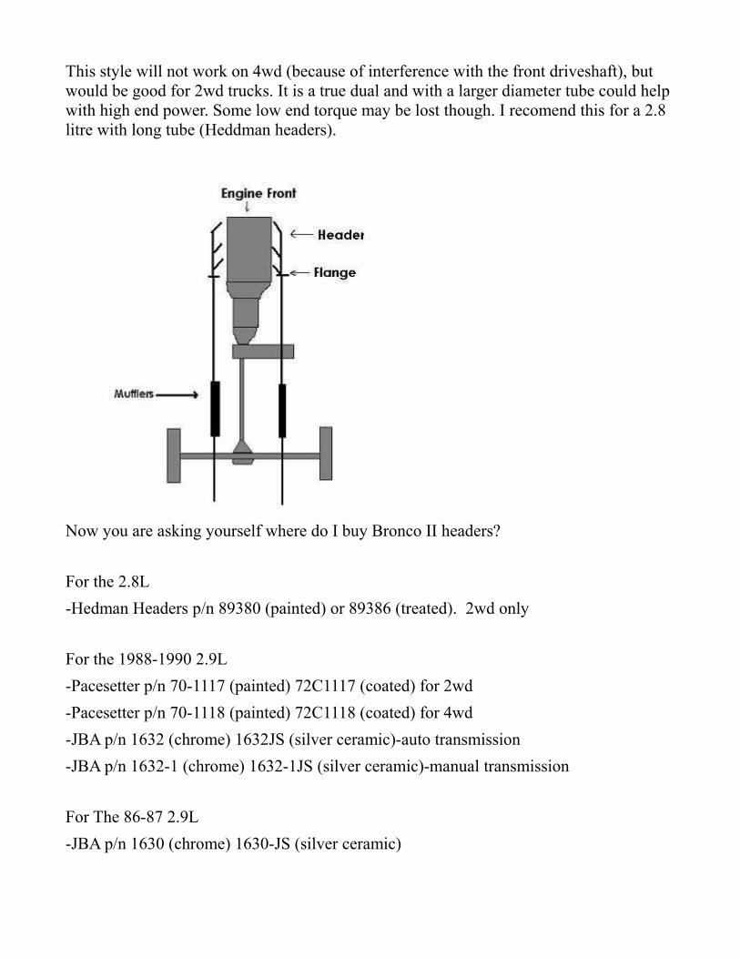
This style will not work on 4wd (because of interference with the front driveshaft), but would be good for 2wd trucks. It is a true dual and with a larger diameter tube could help with high end power. Some low end torque may be lost though. I recomend this for a 2.8 litre with long tube (Heddman headers).
Now you are asking yourself where do I buy Bronco II headers?
For the 2.8L-Hedman Headers p/n 89380 (painted) or 89386 (treated). 2wd only
For the 1988-1990 2.9L-Pacesetter p/n 70-1117 (painted) 72C1117 (coated) for 2wd-Pacesetter p/n 70-1118 (painted) 72C1118 (coated) for 4wd-JBA p/n 1632 (chrome) 1632JS (silver ceramic)-auto transmission-JBA p/n 1632-1 (chrome) 1632-1JS (silver ceramic)-manual transmission
For The 86-87 2.9L-JBA p/n 1630 (chrome) 1630-JS (silver ceramic)

Note that the 86 and 87 2.9L uses an EGR tube, and JBA is the only manufacturer that offers a header to support those engines. JBA are the only headers that have threaded oxygen sensor ports. I have not found a manufacturer for 4x4 2.8L headersl; however, you may be able to find a "factory" Ford 2.8L header found on early Aerostar vans with the 2.8L V6. These are short tube headers and should work with a Y-pipe. If you have more questions about the headers, contact the manufacture (they all have websites).
2.8L V-6 Ranger Fuel Injection Installation For the 2.9L/3.8L hybrid fuel injection conversion
The following is a brief description of how to install a Central Fuel Injection (CFI) system onto a 2.8 liter and what components are needed. Keep in mind that this conversion takes a bit of time and patience.
Components:
First you will need a complete 2.9 liter fuel injection engine harness and Power-train Control Module (PCM) from a Ford Ranger or Bronco II. Second, you will need a 3.8 liter fuel injection throttle body from any rear wheel drive Ford car with a 3.8 liter. The 3.8 liter used in a Ford Taurus is the Wrong fuel injection system(it is the multi-port type), it must be a TBI (Throttle-body fuel injection) unit (with only two injectors) removed from a Mustang, LTD II, Thunderbird, or Cougar. This system has a throttle body similar to a carburetor.
You will want to start out by removing the original Ranger carburetor and computer wiring harness, original PCM, and all vacuum lines and solenoids, leaving the engine compartment free of all original computer equipment. The sensors and vacuum solenoids from the 2.9 need to be used, as the 2.8 liter units will not plug into the harness. The exception I found is the 6-wire plug for the TFI module on the distributor, which will plug into the 2.8 distributor.
The sensors and components needed are: Coolant temp sensor (not for the gauge), Manifold absolute pressure sensor, Heated O2 sensor, Air charge temperature sensor, idle speed control air bypass valve, EVR solenoid, and EGR valve. The throttle position sensor, idle speed control motor, and injector assembly will already be mounted on the 3.8L TBI unit. You will need to remove the idle speed control motor from the TBI unit. You will also need the connectors (from the harness) that plug into the throttle position sensor and the injector array.
The other parts needed are as follows:
Fuel pump relay and inertia switch. Fuel pump (I used an after market Holley) High pressure fuel filter Fuel pressure regulator (optional)
P/N: 510-512-103 - Holley in-line Universal High Pressure Electric Fuel Pump

P/N: 510-512-500-1 - Holley Fuel Pressure Regulator
Note: When removing the PCM and wiring harness from the 2.9 liter engine be sure to LABEL EVERYTHING, you will save yourself a lot of trouble.
Details:
The computer, if operational, will work well on the 2.8 liter engine. When routing the wiring try to keep it as close to the original path as possible, though some lengthening and/or shortening will need to be done. The best method for this is to solder the wires and use shrink wrap around them.
As for the fuel pump, the mechanical fuel pump and fuel lines the entire way back to the tank need to be removed and replaced with a high pressure in tank setup. Make a block off plate for the hole left by the mechanical fuel pump, and be sure to remove the push rod from the engine.
One option is to get the steel lines from the 2.9 Ranger FI tank and ALL associated lines, wiring and pumps, these will need to be installed into your Bronco II or Ranger.
Another option for the fuel pump is to install an inline electric pump near the fuel tank. If this method is chosen, install a high pressure fuel filter after the pump, and run the return line back to the fuel tank filler neck. I installed the pump very close to the fuel tank and ran a high pressure fuel line up to the engine compartment. This fuel line is very expensive, so the shorter the better. I then installed a high pressure fuel filter from Summit Racing, and continued to the TBI. For the return line I ran a short rubber hose to the original steel line and then from the end of the original line near the tank I ran a rubber hose to an AN style bulkhead fitting into the filler neck of the fuel tank. For safety, you may also wish to incorporate an inertia switch into the electrical side of the system. The fuel pressure needs to be at 39 PSI, and should be kept in that neighborhood.
As far as wiring goes, you will need a diagram from the 2.9L and your Ranger. The electrical harness on the driver’s side of the vehicle will supply the required powers, and the grounds should just go to the frame or chassis. Be extremely careful when wiring the
ECM, if you’re not sure about which wires go where, asked somebody. The ECM can be destroyed if wired wrong, and a lot of time and patience lost.
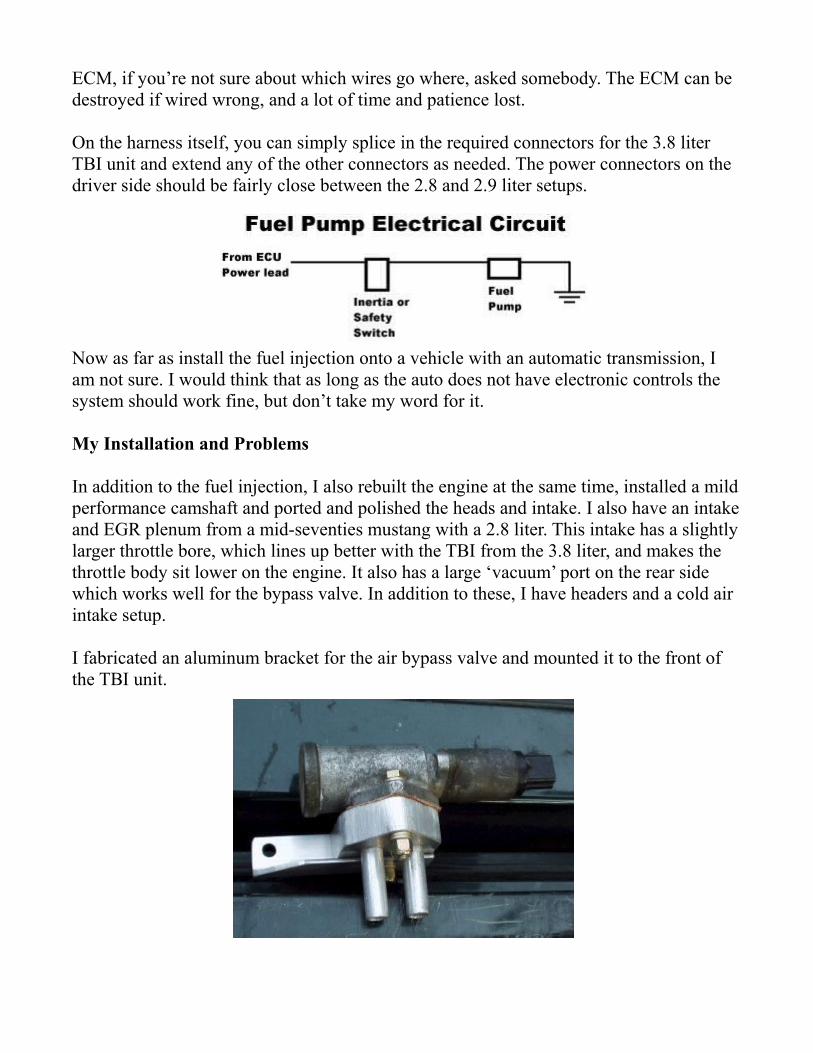
On the harness itself, you can simply splice in the required connectors for the 3.8 liter TBI unit and extend any of the other connectors as needed. The power connectors on the driver side should be fairly close between the 2.8 and 2.9 liter setups.
Now as far as install the fuel injection onto a vehicle with an automatic transmission, I am not sure. I would think that as long as the auto does not have electronic controls the system should work fine, but don’t take my word for it.
My Installation and Problems
In addition to the fuel injection, I also rebuilt the engine at the same time, installed a mild performance camshaft and ported and polished the heads and intake. I also have an intake and EGR plenum from a mid-seventies mustang with a 2.8 liter. This intake has a slightly larger throttle bore, which lines up better with the TBI from the 3.8 liter, and makes the throttle body sit lower on the engine. It also has a large ‘vacuum’ port on the rear side which works well for the bypass valve. In addition to these, I have headers and a cold air intake setup.
I fabricated an aluminum bracket for the air bypass valve and mounted it to the front of the TBI unit.
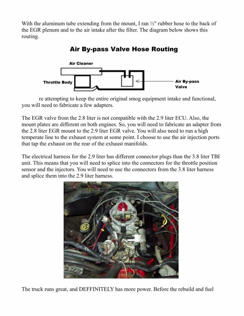
With the aluminum tube extending from the mount, I ran ½" rubber hose to the back of the EGR plenum and to the air intake after the filter. The diagram below shows this routing.
If you are attempting to keep the entire original smog equipment intake and functional, you will need to fabricate a few adapters.
The EGR valve from the 2.8 liter is not compatible with the 2.9 liter ECU. Also, the mount plates are different on both engines. So, you will need to fabricate an adapter from the 2.8 liter EGR mount to the 2.9 liter EGR valve. You will also need to run a high temperate line to the exhaust system at some point. I choose to use the air injection ports that tap the exhaust on the rear of the exhaust manifolds.
The electrical harness for the 2.9 liter has different connector plugs than the 3.8 liter TBI unit. This means that you will need to splice into the connectors for the throttle position sensor and the injectors. You will need to use the connectors from the 3.8 liter harness and splice them into the 2.9 liter harness.
The truck runs great, and DEFFINITELY has more power. Before the rebuild and fuel

injection conversion, I could never get the tires to even chirp, but now I can actually leave some rubber.
I hear the original carburetor in a 2.8L was rated at about 280 CFM, where as the CFI throttle body is closer to 350 CFM (From TRS posts). Larger exhaust will really help, and if time permits add a mild performance camshaft for increased power. The CFI also gives the 2.8 liter a nice idle sound.
The following photo is with the K&N air plenum installed. Yet to be added is a 4" intake tube to a remote K&N style filter. This tube will include two small ports for the air by-pass valve and the PCV tubing. I might include a heat shield to aid in cold air intake.
2.9 Liter EFI Wire to Pin Location and Color Codes
Pin Number Wire Color Use1 Yellow/Black Keep-Alive Power2 Light Green Brake on-off (BOO)3 Dark Green/White Vehicle Speed Sensor (+)4 Dark Green/Yellow Ignition Diagnostic Monitor5 Red/Light Green Ignition Power (Switched) ????????????6 Black/White Vehicle Speed Sensor (-)7 Light Green/Yellow Engine Coolant temperature Sensor8 Orange/Light Blue Fuel Pump Monitor9 ---------- ----------10 Tan/Yellow A/C Compressor Clutch
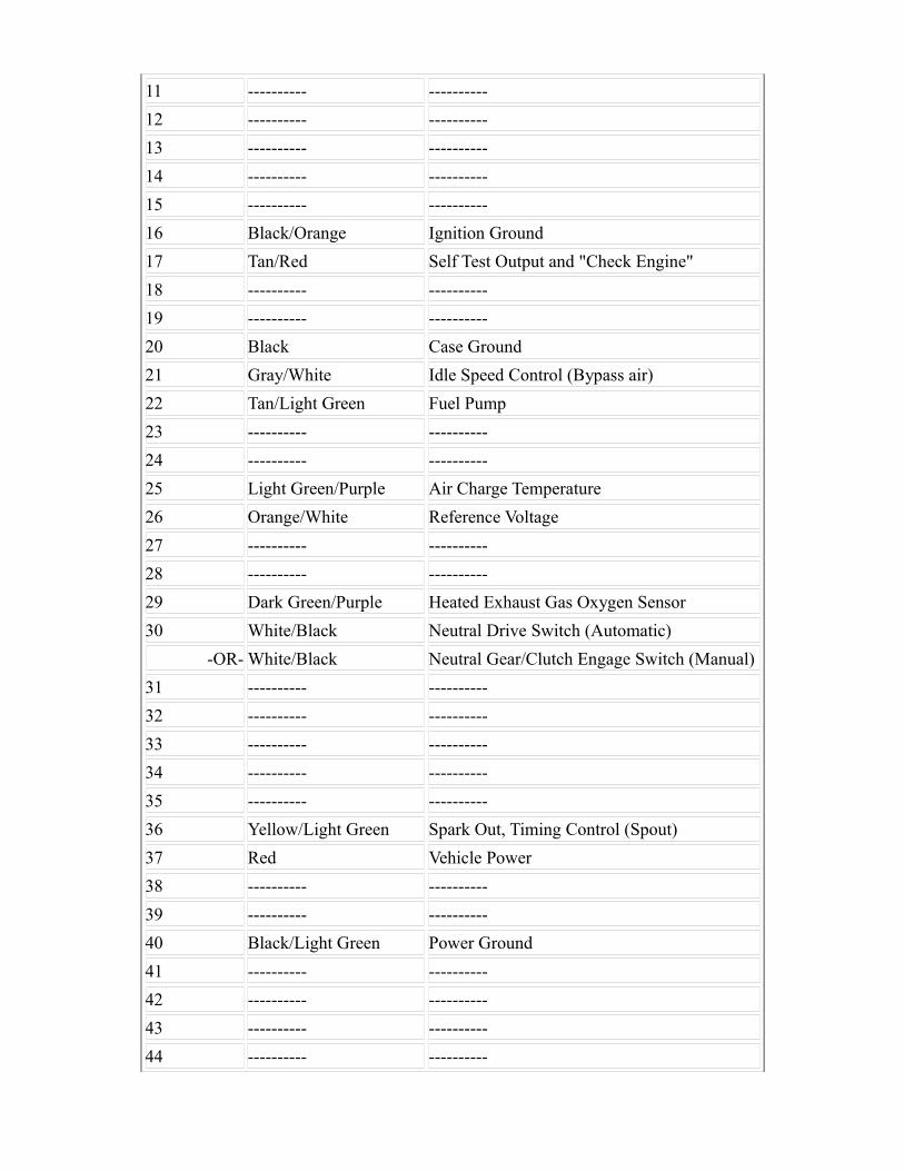
11 ---------- ----------12 ---------- ----------13 ---------- ----------14 ---------- ----------15 ---------- ----------16 Black/Orange Ignition Ground17 Tan/Red Self Test Output and "Check Engine"18 ---------- ----------19 ---------- ----------20 Black Case Ground21 Gray/White Idle Speed Control (Bypass air)22 Tan/Light Green Fuel Pump23 ---------- ----------24 ---------- ----------25 Light Green/Purple Air Charge Temperature26 Orange/White Reference Voltage27 ---------- ----------28 ---------- ----------29 Dark Green/Purple Heated Exhaust Gas Oxygen Sensor30 White/Black Neutral Drive Switch (Automatic)
-OR- White/Black Neutral Gear/Clutch Engage Switch (Manual)31 ---------- ----------32 ---------- ----------33 ---------- ----------34 ---------- ----------35 ---------- ----------36 Yellow/Light Green Spark Out, Timing Control (Spout)37 Red Vehicle Power38 ---------- ----------39 ---------- ----------40 Black/Light Green Power Ground41 ---------- ----------42 ---------- ----------43 ---------- ----------44 ---------- ----------
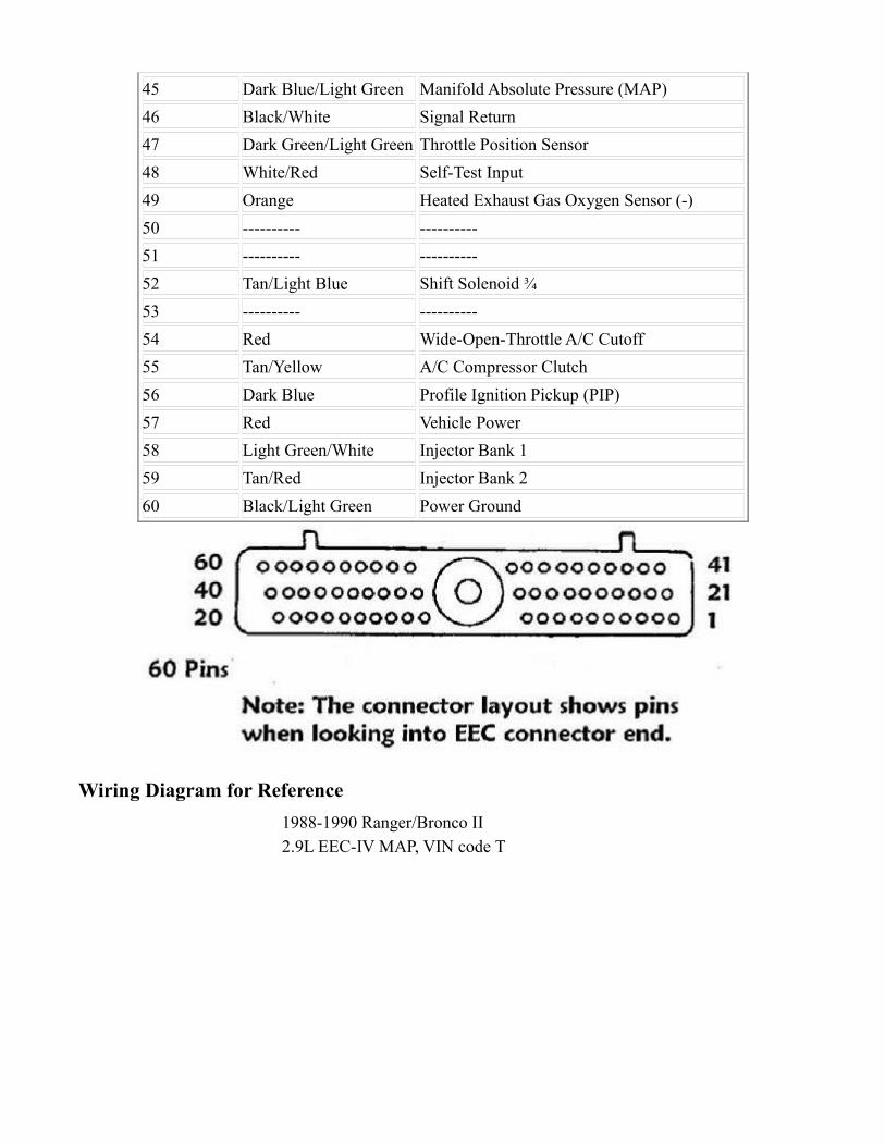
45 Dark Blue/Light Green Manifold Absolute Pressure (MAP)46 Black/White Signal Return47 Dark Green/Light Green Throttle Position Sensor48 White/Red Self-Test Input49 Orange Heated Exhaust Gas Oxygen Sensor (-)50 ---------- ----------51 ---------- ----------52 Tan/Light Blue Shift Solenoid ¾53 ---------- ----------54 Red Wide-Open-Throttle A/C Cutoff55 Tan/Yellow A/C Compressor Clutch56 Dark Blue Profile Ignition Pickup (PIP)57 Red Vehicle Power58 Light Green/White Injector Bank 159 Tan/Red Injector Bank 260 Black/Light Green Power Ground
Wiring Diagram for Reference1988-1990 Ranger/Bronco II2.9L EEC-IV MAP, VIN code T

Click image to view full sizeAuthor: Emanuel Perez

Duraspark Ignition Swap
Duraspark conversion for the Ford 2.8L V6.
The 2.8 carbureted V6, used in 1983-1985 Rangers, and 1984-1985 Bronco II's, had a computer controlled feedback carb and a distributor that had its timing completely controlled by the computer. There is no mechanical advance in the distributor. Ford called this ignition system TFI (Thick Film Integrated). When functioning properly, this system delivers good performance and fuel economy. But when you factor in 20+ year old wiring and bad or missing components, poor mileage and power result. To rid yourself of this computer that constantly tries to adjust the timing and mixture, and often adjusts it wrong, you can convert to the standard electronic ignition and carb that was used on the 70's 2.8L-powered Mustang II, Pinto, Bobcat, and Capri vehicles. This lets you set the tune of the engine, and it stays in that tune, instead of constantly varying as with the TFI system.
For 1983 and 1984 vehicles, this is a plug and play conversion.
For 1985 vehicles, there are some extra wires that need to be spliced together.
For 1985 vehicles with the A4LD Automatic overdrive transmission:Get a GM switch (14014519) and connect it to the solenoid that goes to the lock up. In the line, also install a switch on the brake pedal that will break the circuit when the brake is applied. All you have to do is to drive normal and everything will operate as it did with the computer. I would not use a toggle switch. It seems like it would be a hassle trying to remember to cut it off and on while going down the road.
The switch was mounted on the firewall and connected to engine vacuum. The electrical was connected as follows: A hot wire to the solenoid, the other side of the solenoid and goes to one side of the vacuum switch. The other side of the vacuum switch goes to ground. So when the vacuum switch engages, it connects the circuit to the solenoid.
Now lets go back a little. The hot wire that I ran to the one side of the solenoid comes from a fuse that I installed form inside. It goes from the fuse to a second on/off switch that I mounded on the break pedal. So when I put on the brake, it opens the circuit.
Ford in England did the cars with the A4LD this way. The cars did not have the computer but used a vacuum switch that was made for Ford. These switches are very very hard to
find. These cars were the England Granada's , Merkur and a few others. They had the 2.8 with the A4LD. So you are not doing anything different than what Ford designed for those cars. Since I could not find a Ford vacuum switch, I used the GM switch. In fact, GM controlled their transmission lock up converters with this switch and a dual brake switch that open the circuit.
A4LD info courtesy of AlabamaRanger
*Note*This is NOT considered smog legal. You may be able to remain smog legal by hooking up your EGR, air injection, and ECT, according to the way they were on a 70's 2.8L. I make no guarantees to you that you will pass smog, or any other warranty or guarantee of your mechanical competence. If you mess up your rig, you're on your own.
Parts list:Distributor from a 79 2.8L Pinto. Ask for the non-Bosch style distributor. Single or dual diaphram works fine.
Canister style coil for a Duraspark vehicle or an Accell or MSD style canister coil.New stock coil: ~ $20New Accell or MSD coil: ~ $30While you're looking for the harness, grab the coil mounting bracket too. However, if you don't, an aftermarket universal coil bracket will work.
Module to distributor/coil harness from a mid 70's- mid 80's Ford Duraspark equipped vehicle.If you can't find one, don't worry. You can just make your own by using wire to connect to same color wires together on the distributor and module, and then run "Key-On" 12V power to the (+) side of the coil, and the green module wire to the (-) side of the coil.
Carburetor: The 78 Pinto carb works well on stock engines. If your 2.8 is more performance oriented, or has headers and upgraded exhaust, you may want to use the 350CFM Holley 2V carb. This carb comes jetted for a V8 with ~#61 jets. A good jet size to start tuning a 2.8 with is #54 jets.What about the stock feedback carb? Well, I ran it with everything unplugged for a while, but it ran too rich. Also, many have warped castings. I've run into several.New Pinto carb: ~ $150New 350 Holley: ~ $230
Ignition module: Either get a module from the junkyard, or get a new one for a 78 Pinto. Either way, you want to make sure the plastic grommet where the wires come out of the
module is the "blue" colored one. New is about $20.
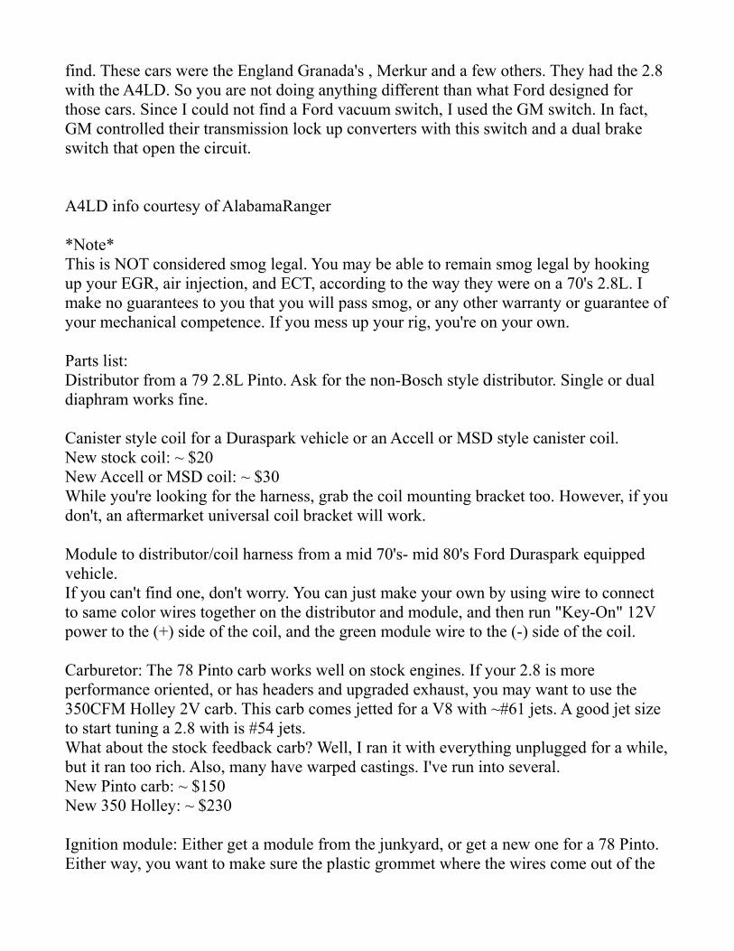
First, most people remove the computer and its associated wiring along with the solenoid bank on the passenger fender well.
The easiest way to start is to locate the temperature sender for the gauge or light, the oil pressure sensor wire, and the three alternator wires. Separate them from the computer harness, and remove the rest.Click on all pictures to see larger versions:
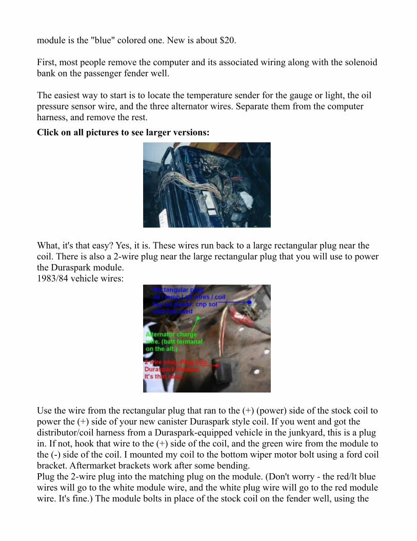
What, it's that easy? Yes, it is. These wires run back to a large rectangular plug near the coil. There is also a 2-wire plug near the large rectangular plug that you will use to power the Duraspark module.1983/84 vehicle wires:
Use the wire from the rectangular plug that ran to the (+) (power) side of the stock coil to power the (+) side of your new canister Duraspark style coil. If you went and got the distributor/coil harness from a Duraspark-equipped vehicle in the junkyard, this is a plug in. If not, hook that wire to the (+) side of the coil, and the green wire from the module to the (-) side of the coil. I mounted my coil to the bottom wiper motor bolt using a ford coil bracket. Aftermarket brackets work after some bending.Plug the 2-wire plug into the matching plug on the module. (Don't worry - the red/lt blue wires will go to the white module wire, and the white plug wire will go to the red module wire. It's fine.) The module bolts in place of the stock coil on the fender well, using the
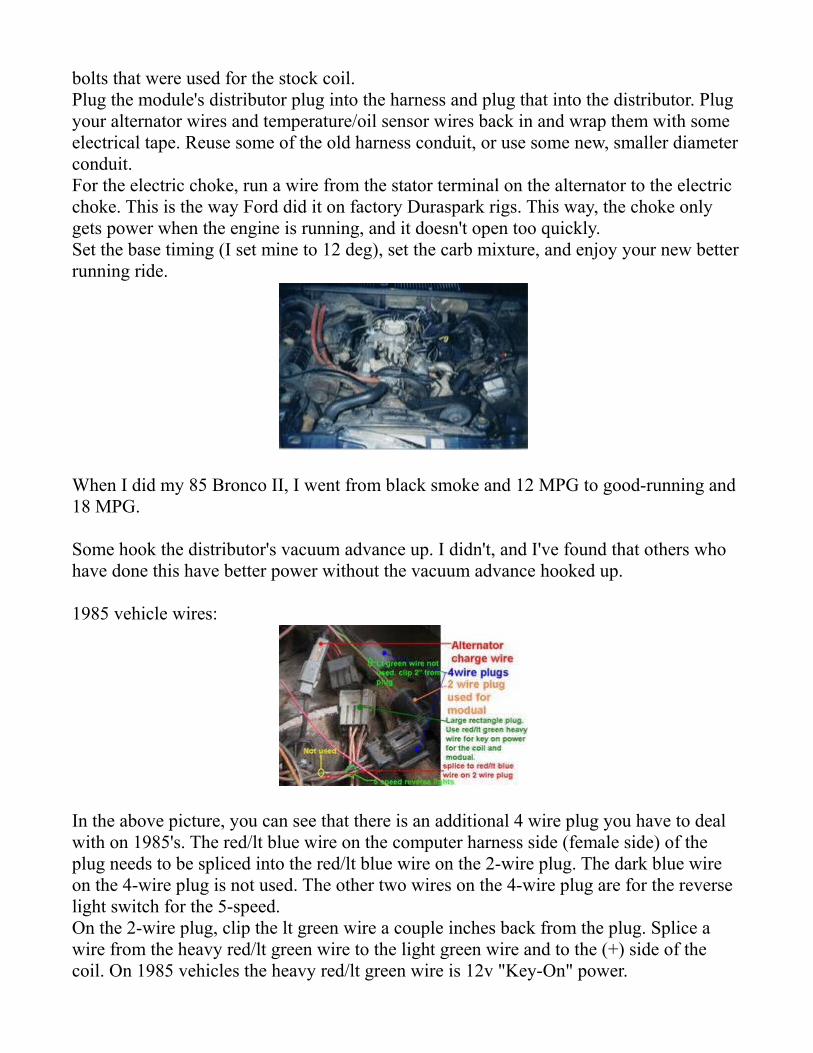
bolts that were used for the stock coil.Plug the module's distributor plug into the harness and plug that into the distributor. Plug your alternator wires and temperature/oil sensor wires back in and wrap them with some electrical tape. Reuse some of the old harness conduit, or use some new, smaller diameter conduit.For the electric choke, run a wire from the stator terminal on the alternator to the electric choke. This is the way Ford did it on factory Duraspark rigs. This way, the choke only gets power when the engine is running, and it doesn't open too quickly.Set the base timing (I set mine to 12 deg), set the carb mixture, and enjoy your new better running ride.
When I did my 85 Bronco II, I went from black smoke and 12 MPG to good-running and 18 MPG.
Some hook the distributor's vacuum advance up. I didn't, and I've found that others who have done this have better power without the vacuum advance hooked up.
1985 vehicle wires:
In the above picture, you can see that there is an additional 4 wire plug you have to deal with on 1985's. The red/lt blue wire on the computer harness side (female side) of the plug needs to be spliced into the red/lt blue wire on the 2-wire plug. The dark blue wire on the 4-wire plug is not used. The other two wires on the 4-wire plug are for the reverse light switch for the 5-speed.On the 2-wire plug, clip the lt green wire a couple inches back from the plug. Splice a wire from the heavy red/lt green wire to the light green wire and to the (+) side of the coil. On 1985 vehicles the heavy red/lt green wire is 12v "Key-On" power.
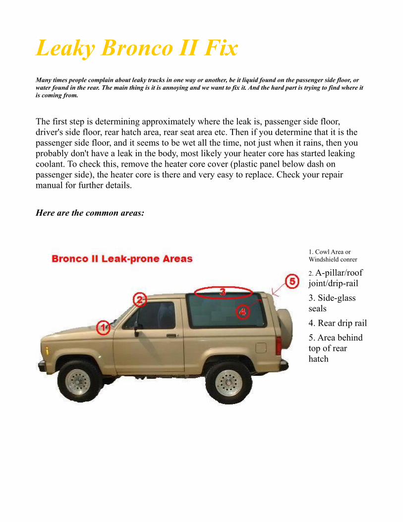
Leaky Bronco II Fix
Many times people complain about leaky trucks in one way or another, be it liquid found on the passenger side floor, or water found in the rear. The main thing is it is annoying and we want to fix it. And the hard part is trying to find where it is coming from.
The first step is determining approximately where the leak is, passenger side floor, driver's side floor, rear hatch area, rear seat area etc. Then if you determine that it is the passenger side floor, and it seems to be wet all the time, not just when it rains, then you probably don't have a leak in the body, most likely your heater core has started leaking coolant. To check this, remove the heater core cover (plastic panel below dash on passenger side), the heater core is there and very easy to replace. Check your repair manual for further details.
Here are the common areas:
1. Cowl Area or Windshield conrer
2. A-pillar/roof joint/drip-rail3. Side-glass seals4. Rear drip rail5. Area behind top of rear hatch

1: Cowl vent. This is mainly a problem on the first-generation (84-88) bronco II. Leaves and other debris will clog the drain vents and will cause moisture to sit and create rust
holes. Symptoms: Wet front carpet, water in glove box. If caught in time, it is possible to remove the access covers under the hood and spread seam-sealer in the holes, but if its a fairly large hole, the fenders have to come off, the cowl panel has to be removed (lots of spot-weld drilling) and the rusted metal has to be replaced. I should
mention this isn't as much of a problem on later (89-90) bronco II's because the cowl was changed from slots to a "mesh" pattern to prevent most debris from entering.
Note that on the inner side of the fire wall, in the passenger compartment where the bottom corners of the windshield is, is a very common area for water to leak in. This area tends to rust and allow lots of water in when it is wet. It usually happens first on the passenger side, then later on the drivers side rusts. In order to access this area the dash must partially be removed. The old sealant will have to be removed, and all rust ground away, then new sealant installed. See photos below:
2: A-pillar/roof joint/drip-rail. This is a VERY common leak on BII's no matter the year. The seam sealer gets brittle with age and either cracks or crumbles away leaving an open seam. It can also be hidden behind the windshield trim. Symptoms are wet floorboard and a drip from the headliner just past the windshield. A temp fix is to smear silicone down in the cracks and joints with your finger. This will stop the leak for a little while until the rest of the seam sealer cracks. Best fix is to dig all of the old seam-sealer out and put new sealer in.

3: Side-glass seals. These are usually easier to spot as most of the time the leak will run down the inside of the glass when it rains. Symptoms are wet cargo-carpet and streaks on the inside of a foggy window. The fix is pretty simple, just time consuming. Basically you have to remove all of the interior trim for that side of the truck, un-bolt the glass, and with an assistant work a screw diver under the glass enough to run a piece of piano wire or some wire thin enough to cut what's left of the seal. DO NOT try to force the glass out or else you will shatter the glass, end up with cuts, have a nice open hole in your BII, and have to drop a good chunk of money for a replacement (and they're not cheap.)
After the glass is out, clean the sealing surfaces as best as you can, and apply some "tar ribbon" around the sealing surface of the glass. You can get the tar ribbon at just about any automotive store or windshield shop. Everything else is reverse of removal.
4: Rear drip rail. Why ford put these on is beyond me, but they too can cause leaks. Basically the same was as number 2. Seam sealer dries, cracks, leaks. Symptoms are wet cargo carpet. The fix is the same as number 2's.
5: Area behind top of rear hatch. Once again, seam sealer is the problem, but this time there is a bunch of it. symptoms are wet rear headliner and wet cargo carpet. There really isn't a good temp fix for this because there is so much seam sealer that you'll spend more time smearing silicone over it than it would take to break all of the seam sealer out and replace it. All of the leaks above can lead to rust that puts the strength of the body in question. Rust around the front and rear body to frame bolts can be a problem, especially in a collision. The best way to fix it is to catch it before it starts.
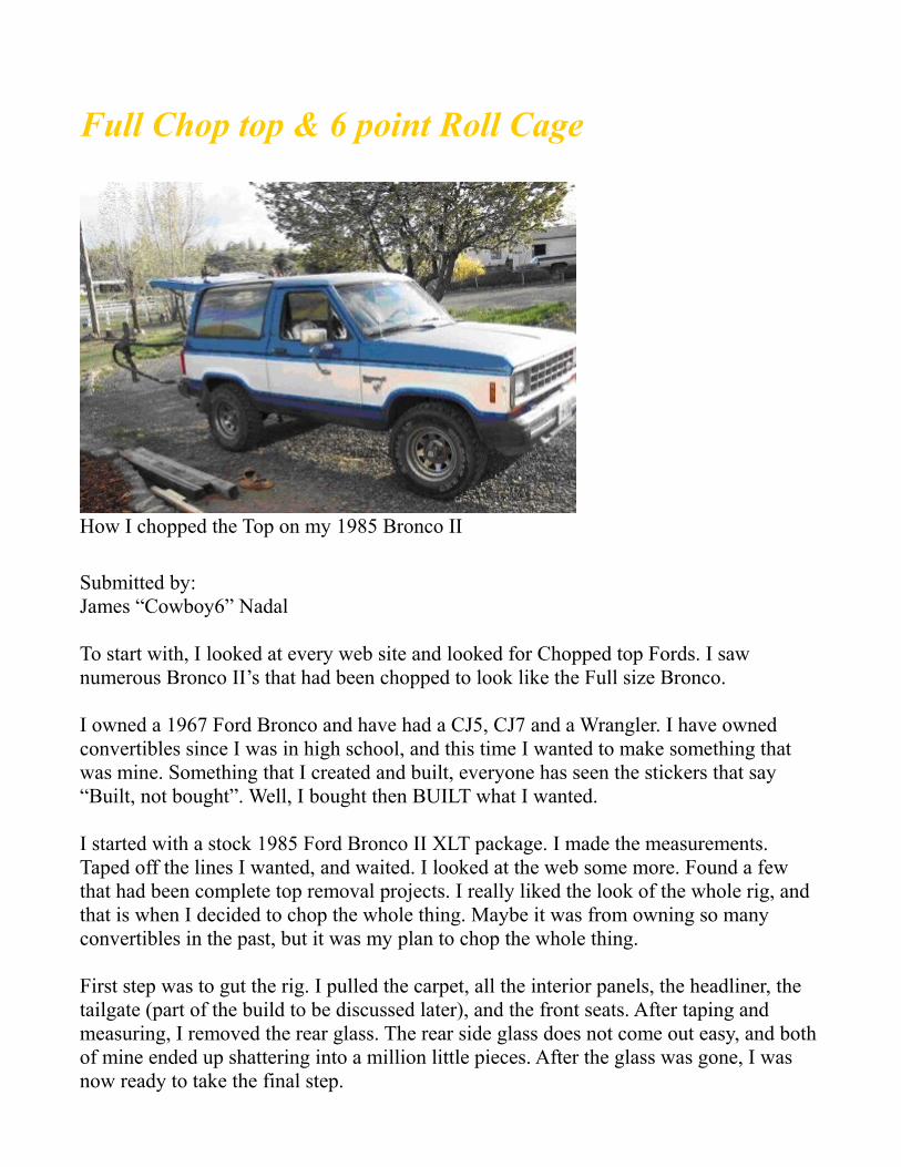
Full Chop top & 6 point Roll Cage
How I chopped the Top on my 1985 Bronco II
Submitted by:James “Cowboy6” Nadal
To start with, I looked at every web site and looked for Chopped top Fords. I saw numerous Bronco II’s that had been chopped to look like the Full size Bronco.
I owned a 1967 Ford Bronco and have had a CJ5, CJ7 and a Wrangler. I have owned convertibles since I was in high school, and this time I wanted to make something that was mine. Something that I created and built, everyone has seen the stickers that say “Built, not bought”. Well, I bought then BUILT what I wanted.
I started with a stock 1985 Ford Bronco II XLT package. I made the measurements. Taped off the lines I wanted, and waited. I looked at the web some more. Found a few that had been complete top removal projects. I really liked the look of the whole rig, and that is when I decided to chop the whole thing. Maybe it was from owning so many convertibles in the past, but it was my plan to chop the whole thing.
First step was to gut the rig. I pulled the carpet, all the interior panels, the headliner, the tailgate (part of the build to be discussed later), and the front seats. After taping and measuring, I removed the rear glass. The rear side glass does not come out easy, and both of mine ended up shattering into a million little pieces. After the glass was gone, I was now ready to take the final step.

To cut or not…. Well, I cut. And then cut some more.
I started 3 inches above the windshield trim to give myself room for error. There is a bodyline that you will see on the inside of the cab right above the sun-visors. Easy to cut off, but not to put back on. I then cut the B and C pillars at the bodyline at the bottom of the rear windows at the pinch rail. Once the pillars were cut….. remove the top, and now have a convertible. If you break your glass like I did. Use a box knife to cut the glue that was used to hold the glass on the metal. After the top is removed, the rear quarter panels need to be braced. Much like making a bed brace for a truck. The reason for this is the top of the panel right behind the door is now unstable, and has about 2-3 inches of flex. It has some play in it, and the metal needs to be braced to keep from stress tears. I used a piece of ¾ inch conduit with flattened ends to make my support measured at 33 inches and flattened the ends about 4 inches each. I placed brace on the floor behind the seats and used rivets to hold in place and them tied the brace into the side of the wall. After the braces were riveted in place, the flex at the door is gone. After I put the 6-point cage in, I will use the cage to also help stiffen the panels and reduce the amount of body flex. I closed the pillars by using expanding foam and a piece of 1x3 flashing. The foam was to close the holes, and the flashing was to smooth the bodylines and make everything flow. The windshield frame was another project in and of itself. I actually rolled the metal back to the pinch line on the roof. I then used foam again in the cavity, cut the metal and shave the foam to the line I wanted, and then to close the metal with the body line that I left long. I then took the tailgate and cut the top half along the same bodyline as the top. Then split it down the middle to make swing out doors and will use a hinge on the door and rear of the bronco to mount them. I also cut the top half of the doorframe off. The back of the

door is along the bodyline, and the front is at the top angle of the frame.
For the rear of the body. I still had the pinch seam on the sides. I actually folded over 90* flat on the sides to help maintain the structural strength of the sides. (actually beat them over with a hammer and cresant wrench to start the bend). I also used a piece of 1x3 (90* bend) flashing cut at 53.5 inches to smooth the line on the top and close off the pillar tops. Rivets used and not welds.
Now for the inside. You can reuse the interior panels, just need to cut them to match the new body, ( this is mostly if you reuse the interior panels) or you can use diamond plate, or just about anything you like to finish the interior.
To Cage or Not to Cage.
This is almost a have to do project if you are going to do any type of wheeling. The windshield frame is not strong enough to support the roll, and there is no longer any overhead protection. I built a 8 point cage that was fabricated from 2 existing.
I built my roll cage from a 6 point CJ5 cage and a Rear roll bar from a CJ7
The front cage had to be narrowed by 5 inches and sleeved back together. 25 ¼ inch spreader bars tie the front hoop to the main hoop. The outside spreader bars were also shortened by about 6 inches, refit and welded into place. I used a piece of 2x2 stock and ran it from frame rail to frame rail and then braced under the floor to the floor plate on the main hoop. The front hoop has frame braces from the frame rail out to the plate and bolts in. The rear bar is 38 inches from the floor to the tops of each bend, and 39.5 to the center. Each spreader bar is 38 inches long and follows the front spreader back to give it a
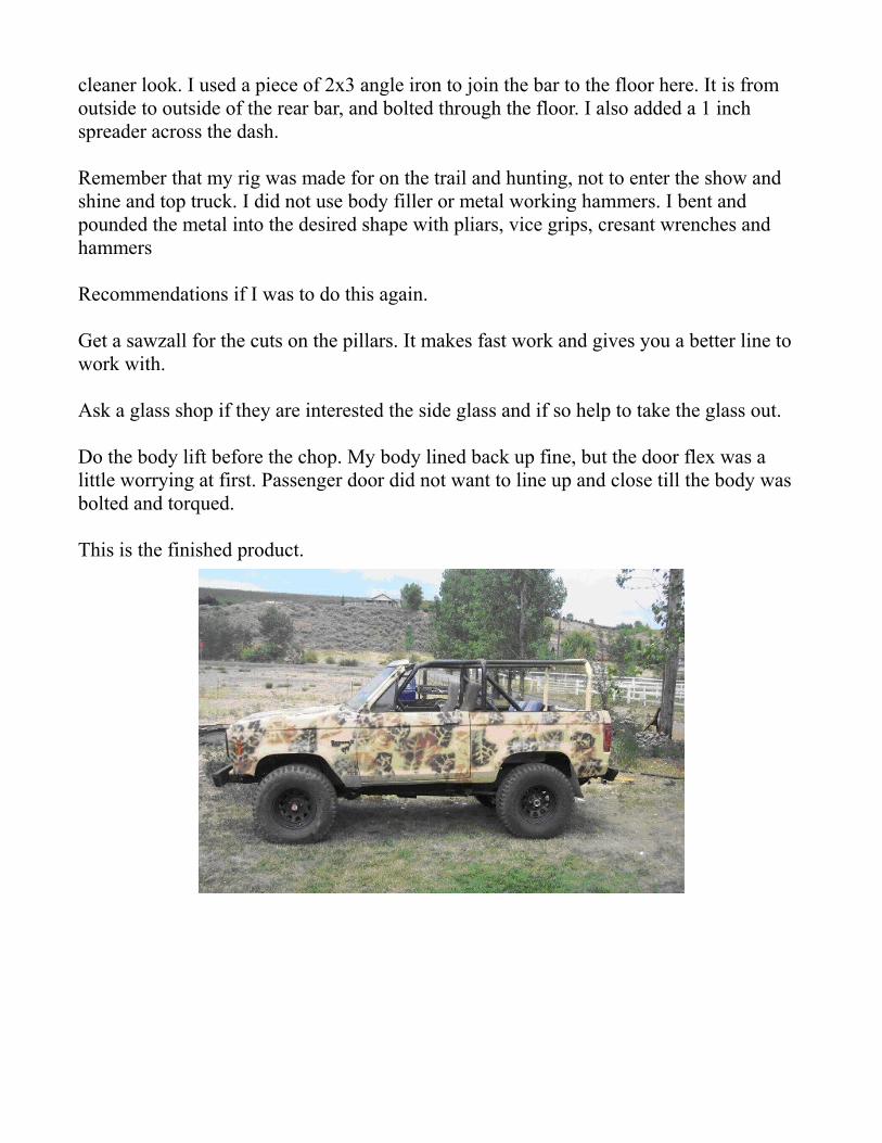
cleaner look. I used a piece of 2x3 angle iron to join the bar to the floor here. It is from outside to outside of the rear bar, and bolted through the floor. I also added a 1 inch spreader across the dash.
Remember that my rig was made for on the trail and hunting, not to enter the show and shine and top truck. I did not use body filler or metal working hammers. I bent and pounded the metal into the desired shape with pliars, vice grips, cresant wrenches and hammers
Recommendations if I was to do this again.
Get a sawzall for the cuts on the pillars. It makes fast work and gives you a better line to work with.
Ask a glass shop if they are interested the side glass and if so help to take the glass out.
Do the body lift before the chop. My body lined back up fine, but the door flex was a little worrying at first. Passenger door did not want to line up and close till the body was bolted and torqued.
This is the finished product.

Total cost:
$500.00 for Bronco II$250.00 for parts truck ( mainly for wheels and tires, extra tranny and transfer, axles)$30.00 for the paint. I used Rustoleum Oil Based flat white that I had mixed to the tan and then the new Krylon Camo spray paint. All paint is flat colors and no shine.Author: James Nadal (Cowboy6)
Submitted by: James Nadal (Cowboy6)
Tech. Page created and edited by: Brian M. Rhoades (NightKrawler)

Cowl Induction
Introduction
Many people complain about getting mud and water in the air box and possibly into the engine through the air filter due to the stock location of the air intake tube. The stock location on a 2.9 sucks air from the grille area about 6" below the air box. By adapting the air intake so that it draws air from the cowl area allows for less of a chance of water entering the system, and since the cowl is so much higher, it is safe to say that it is unlikely that much water will enter unless the water you are driving through is as deep as the hood. The cowl area has a lot of natural air flow and drainage on both the drivers and passenger's side, which makes it a prime area for the intake.
Although this procedure is easily possible with a 4 cylinder (Ranger), 2.8L V6, or V8 conversion, we will be discussing two different methods for the 2.9L. The first method is on my '88BII with the newer style air box, and the second is on Hair's '87BII with the older style angled air box.
Version 1
What I did was remove the stock air intake tube, and cut off the angled part that attaches to the air box (stock part, in first picture). By inverting the part then reinserting it into the air box it turns up and back, rather than forward and down (perfect for cowl induction). Then after spending a few minutes at the local wreckers, I saw the air intake tube off of a 1984 (carbureted) Tempo. I used an epoxy to mount the air box side of the Tempo's tube inside the part of the BII's tube that was cut, and wrapped the joint in black tape for cosmetic purposes. Next I cut a hole above the heater blower motor the size of the square plastic opening on the Tempo's intake tube (right hand side part in the first photo clips into the hole seen in the second photo). In the third photo you can see how the whole system mounts.
Points to note are that the intake tube now runs really close to where the hood bracket enters the firewall. There is not enough clearance to close the hood on a stock truck, so this is only possible if there is a 2 or 3" body lift installed on the

vehicle. Also, you will need to run a bead of silicon along the front bottom of the opening above the blower motor housing to prevent and liquid from going into the air box. I also left the stock drainage hole in the bottom of the air box to allow any unexpected water to dissipate.
Version 2 (submitted by Hair)
The first time I crossed a deep puddle with my 87 B II I found out where the stock air intake was. low in the grill, so I felt I had to fix it. Pulling the air box apart I covered the stock air inlet with a sheet of steel pop riveted in place and applied silicone. At the rear left of the air box facing the engine I used a 3" hole saw as low and as far back as possible and poked a hole. I went out and got 1' of 3" exhaust pipe and cut about 6" off and mounted it in the air box using 2 bolts and nuts through the rear of the box and used silicone to seal the new air intake. Now to the cowl. I moved the MAP sensor and used the 3" hole saw as high up in the cowl as I could. I took the rest of the 3" pipe and pushed it in to the cowl. mounting it with a sheet metal screw thru the flange at the top of the cowl. 3" ducting from the auto parts store connected the two tubes. the MAP sensor was remounted below the new cowl air intake. it works great! No one told me what to do, or how to do it. I just did it.
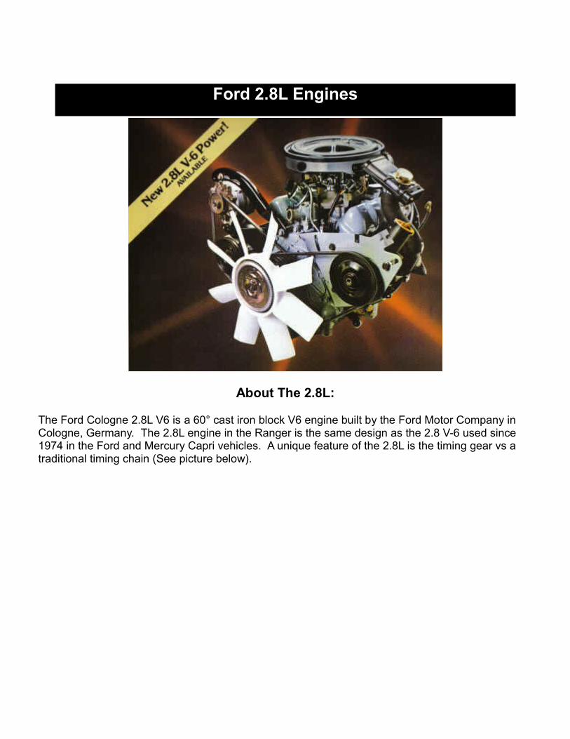
Ford 2.8L Engines
About The 2.8L:
The Ford Cologne 2.8L V6 is a 60° cast iron block V6 engine built by the Ford Motor Company in Cologne, Germany. The 2.8L engine in the Ranger is the same design as the 2.8 V-6 used since 1974 in the Ford and Mercury Capri vehicles. A unique feature of the 2.8L is the timing gear vs a traditional timing chain (See picture below).
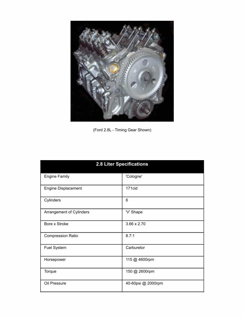
(Ford 2.8L - Timing Gear Shown)
2.8 Liter Specifications
Engine Family 'Cologne'
Engine Displacement 171cid
Cylinders 6
Arrangement of Cylinders 'V' Shape
Bore x Stroke 3.66 x 2.70
Compression Ratio 8.7:1
Fuel System Carburetor
Horsepower 115 @ 4600rpm
Torque 150 @ 2600rpm
Oil Pressure 40-60psi @ 2000rpm

Tune Up
Spark Plug AWSF-42C
Spark Plug Gap 0.044
Ignition Timing 10 degrees BTDC
Firing Order 1-4-2-5-3-6
Distributor Rotation Clockwise
Valve Clearance Intake 0.014
Valve Clearance Exhaust 0.016
Capacities
Oil Capacity With Filter 5qts
Cooling System Capacity (Quarts) W/AC- 7.2 / W/O AC 7.8
Torque Specifications
Cylinder Head 70-85 ft-lbs [3-steps (29-40) (40-51) (70-85)]
Main Bearing Bolts 65-75 ft-lbs
Rod Bearing Bolts 19-24 ft-lbs
Crank Pulley Bolts 85-96 ft-lbs
Flywheel to Crankshaft Bolts 47-52 ft-lbs
Intake Manifold15-18 ft-lbs [5-steps (hand start & snug) (3-6) (6-11) (11-15) (15-18) (Repeat 15-18 after warm up)]
Exhaust Manifold 20-30 ft-lbs
Valve Specifications
Seat Angle Degree 45
Face Angle Degree 44

Spring Test Pressure 143lbs @ 1.22in
Spring Installed Height 1.58-1.61in
Stem-to-Clearance Intake 0.0008-0.0025in
Stem-to-Clearance Exhaust 0.0018-0.0035in
Stem Diameter Intake 0.3159-0.3167in
Stem Diameter Exhaust 0.3149-0.3156in
Crankshaft Specifications
Main Bearing Journal Diameter 2.2433-2.2441in
Main Bearing Oil Clearance 0.0008-0.0015in
Shaft End-play 0.004-0.008in
Thrust on No. 3
Connecting Rod
Journal Diameter 2.1252-2.1260in
Oil Clearance 0.0006-0.0016in
Side Clearance 0.004-0.011in
Length 5.1386-5.1413in
Piston & Ring Specifications
Piston to Bore Clearance 0.0011-0.0019in
Ring Side Clearance Top Compression 0.0020-0.0033in
Ring Side Clearance Bottom Compression 0.0020-0.0033in
Ring Side Clearance Oil Control Snug
Ring Gap Top Compression 0.015-0.023in
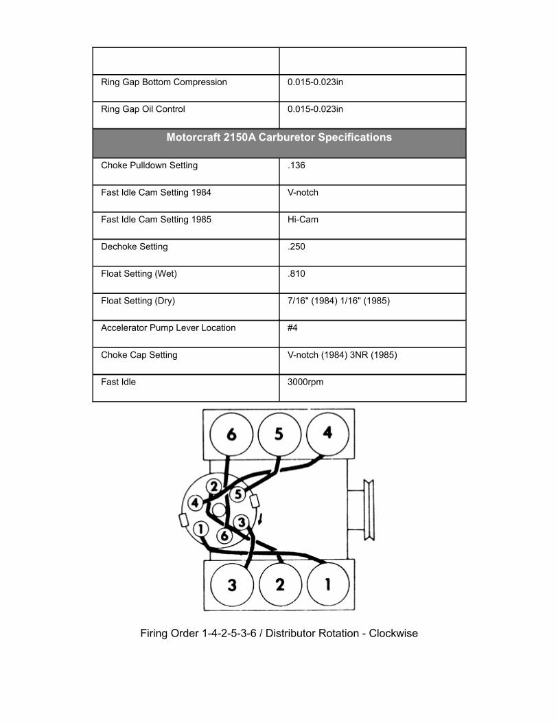
Ring Gap Bottom Compression 0.015-0.023in
Ring Gap Oil Control 0.015-0.023in
Motorcraft 2150A Carburetor Specifications
Choke Pulldown Setting .136
Fast Idle Cam Setting 1984 V-notch
Fast Idle Cam Setting 1985 Hi-Cam
Dechoke Setting .250
Float Setting (Wet) .810
Float Setting (Dry) 7/16" (1984) 1/16" (1985)
Accelerator Pump Lever Location #4
Choke Cap Setting V-notch (1984) 3NR (1985)
Fast Idle 3000rpm
Firing Order 1-4-2-5-3-6 / Distributor Rotation - Clockwise
Known Problems:
Valve Seals - The 2.8L's are known to burn oil and smoke when they get high mileage. They use a rubber valve seal that deteriorates and leaks oil into the cylinder. ClickHERE for information on replacing the valve seals.
Loose Distributor Rotor - Some of the Ford 2.8's came with round distributor rotors. These have (2) screws that hold them in place. There have been reports of them coming loose in the distributor. Click HERE for more information.
TFI Failure - If your truck stops running and wont restart, it could be from a faulty TFI. Click HERE for more information.
Performance Upgrades:
Cylinder Heads:
Cooling - A simple upgrade to the 2.8L heads is to drill two more water passages in them between where the two exhaust valves are side by side. This helps prevent a local boiling point from forming. Just use a good head gasket that already has the water passage holes in them for a guide, and mark the head and drill two holes. Keep the holes a little smaller than the holes in the head gasket. - Contributed By Ryan Propst
Porting - Port your intake manifold and cylinder heads. The intake and heads don't line up diameter to diameter. Porting opens this up and allows better flow. Click HEREfor details on porting.
Induction - Offy 4bbl Intake:
The 2.8L V-6 comes with a 2-bbl carburetor and manifold with a traditional round metal air filter container. Offenhauser offers a 4bbl intake manifold. The ignition system must be changed to earlier vacuum advance unit (Dura-Spark II) eliminating the EEC-IV computer and pollution equipment. You can use the distributor, ignition module and coil from a 78 Pinto. The Offenhauser Intake does not have an EGR setup. This will not allow the A4LD tranny to shift correctly.
The Offenhauser intake can be found at:
Racer Walsh:
www.racerwalsh.zoovy.com/

P/N RWA6110
The Racer Walsh 2.8L aluminum intake manifold is made to work with the RWA6239 4BBL carb. You will need to use the RWA6278 thermostat housing with the new manifold. The intake manifold and carb combo are made for street driving and lower rpm off road applications, such as trail riding and playing in the mud. The installation of the manifold and carb still provide good gas mileage and an easy horsepower improvement.
Click HERE to go to their Offy 4bbl intake page
This intake can also be found at:
www.offyparts.com
P/N offy-6097-DP
Recommend: Holley 0-6299 or 8007
Click HERE to go to their Offy 4bbl intake page.
Performance Automotive Warehouse (www.pawengineparts.com) did carry Offenhauser 4bbl Intake Manifold Part Number 0FF-6097-DP (part of Port-O-Sonic line). Unknown if they still carry it.
Induction - Fuel Injection:
You can also swap on fuel injection using parts from a 3.8L Ford. Check out the 2.8 Fuel
Injection page.
Aftermarket Camshafts:
Competition Cams:
www.compcams.com
Competition Cams carries (3) camshafts for the 2.8L Ford, the 244S, 252S and 264S. Cam descriptions can be found HERE. Those parts can be found at Jegs (www.jegs.com) by searching for those (3) part numbers.
Competition Cams carried camshafts, rocker arms and timing gear for the 2.8L HERE.
THIS PAGE is the main Comp Cams menu for the Ford V6.
Camshafts - Racer Walsh (Also see below):
Racer Walsh offers (2) camshafts for the 2.8L Ford.
Camshaft #1 P/N RWA6411
The stage 1 cam gives a smooth idle as well as a boost in low to mid range power, without sacrificing fuel economy. Please specify the year of your engine when ordering.
Camshaft #2 P/N RWA6412
The Racer Walsh stage 2 V-6 camshaft for the 2.6L/2.8L engines offer a significant power increase from the midrange to top end performance. The Racer Walsh Stage 2 camshaft is a street / competition grind. We recommend a slightly higher than stock stall on the converter if an automatic transmission is used. Please specify the year of your engine when ordering.
Pistons:
Racer Walsh carries 9-1 pistons for the 2.8L Ford HERE.
Exhaust & Air Filters
Motors are just big air pumps. The more air and the more air out the better the performance.
Headers:
Hedman (www.hedman.com) manufactures headers for the 2.8L and Summit Racing still lists a Headman header.
Summit Racing also carries a Dynomax cat-back exhaust kit for the 2.8L.
Air Filters:
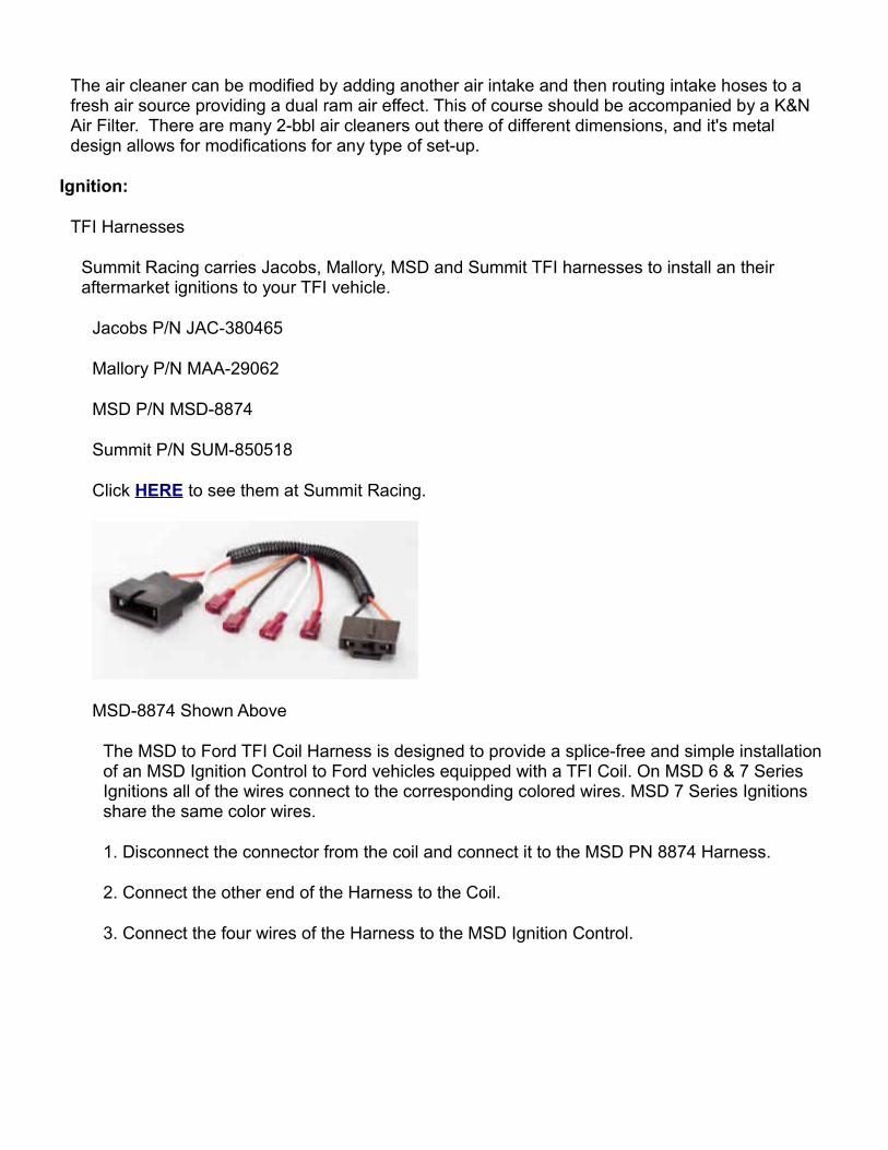
The air cleaner can be modified by adding another air intake and then routing intake hoses to a fresh air source providing a dual ram air effect. This of course should be accompanied by a K&N Air Filter. There are many 2-bbl air cleaners out there of different dimensions, and it's metal design allows for modifications for any type of set-up.
Ignition:
TFI Harnesses
Summit Racing carries Jacobs, Mallory, MSD and Summit TFI harnesses to install an their aftermarket ignitions to your TFI vehicle.
Jacobs P/N JAC-380465
Mallory P/N MAA-29062
MSD P/N MSD-8874
Summit P/N SUM-850518
Click HERE to see them at Summit Racing.
MSD-8874 Shown Above
The MSD to Ford TFI Coil Harness is designed to provide a splice-free and simple installation of an MSD Ignition Control to Ford vehicles equipped with a TFI Coil. On MSD 6 & 7 Series Ignitions all of the wires connect to the corresponding colored wires. MSD 7 Series Ignitions share the same color wires.
1. Disconnect the connector from the coil and connect it to the MSD PN 8874 Harness.
2. Connect the other end of the Harness to the Coil.
3. Connect the four wires of the Harness to the MSD Ignition Control.

MSD Ignition Box Shown Above
Replacement Coils
Summit Racing carries replacement TFI ignition coils. You can view a list of them on the Summit Racing site HERE.
Crane P/N CRN-730-0391
Moroso P/N MOR-72360
MSD P/N MSD-8227
PerTronix P/N PNX-D3000

Pertronix P/N PNX-D3003
ProForm P/N PRO-66959C
Hypertech P/N HYP-4064
TFI Ignition Modules:
Summit Racing carries Accel and PerTronix TFI Ignition Modules.
PerTronix P/N D2010
Accel P/N 35368
Accel P/N 35368 Shown Above
ACCEL control modules provide high coil output & superior reliability. Dwell circuit ensures long coil charging. Current circuit protects from overheating. Resists false triggering from RFI sources. Distributor and remote mounts available.
Available at Summit HERE.
Summit also offers Pertronix P/N PNX-D2010 HERE.
Spark Plug Wires
You should upgrade to 9mm spark plug wires and will have to purchase a set of JBA Powercables or get a set of universal wires and cut them.
Summit Racing carries the JBA Powercables P/N JBA-06309 HERE.
Duraspark Ignition Swaps:
Also check out the Duraspark ignition conversion HERE. Using the Duraspark ignition, you can eliminated the computer, vacuum rail, vacuum reservoir, and all the wiring mess that goes along
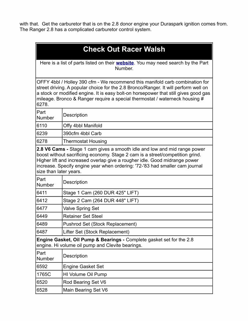
with that. Get the carburetor that is on the 2.8 donor engine your Duraspark ignition comes from. The Ranger 2.8 has a complicated carburetor control system.
Check Out Racer Walsh
Here is a list of parts listed on their website. You may need search by the Part Number.
OFFY 4bbl / Holley 390 cfm - We recommend this manifold carb combination for street driving. A popular choice for the 2.8 Bronco/Ranger. It will perform well on a stock or modified engine. It is easy bolt-on horsepower that still gives good gas mileage. Bronco & Ranger require a special thermostat / waterneck housing # 6278.Part Number Description
6110 Offy 4bbl Manifold6239 390cfm 4bbl Carb6278 Thermostat Housing2.8 V6 Cams - Stage 1 cam gives a smooth idle and low and mid range power boost without sacrificing economy. Stage 2 cam is a street/competition grind. Higher lift and increased overlap give a rougher idle. Good midrange power increase. Specify engine year when ordering: '72-'83 had smaller cam journal size than later years.Part Number Description
6411 Stage 1 Cam (260 DUR 425" LIFT) 6412 Stage 2 Cam (264 DUR 448" LIFT) 6477 Valve Spring Set 6449 Retainer Set Steel6489 Pushrod Set (Stock Replacement)6487 Lifter Set (Stock Replacement) Engine Gasket, Oil Pump & Bearings - Complete gasket set for the 2.8 engine. Hi volume oil pump and Clevite bearings.Part Number Description
6592 Engine Gasket Set 1765C HI Volume Oil Pump 6520 Rod Bearing Set V6 6528 Main Bearing Set V6

1570K ARP Rod BoltsForged Pistons 2.8 - 9-1 forged piston set for the 2800 V6 engine. We stock .030" overbore. Priced per set of 6, includes wrist pins.Part Number Description
6498 Forged Pistons 6499 Pistons RingsMetal Timing Gears - Metal timing gears are more durable than the stock fiber type timing gears.Part Number Description
6548 Timing Gears V6 Miscellaneous:
Miscellaneous Parts List
Part Number Brand Description
CL38-101-4 Competition Cams
Good cam for OEM replacement or rebuild. Low RPM torque with good economy.
CL38-240-4 Competition Cams
Performance with economy, power increase in low-mid RPM range. See note 2. (Good For Auto)
CL38-241-4 Competition Cams
Great for towing and highway use. Strong torque and power increases. (Good For Manual)
6846 Edelbrock Bolt on headers for 2 and 4 wheel drive Rangers.
0FF-6097-DP Offenhauser 4-Barrel intake manifold.0-7448 Holley 350 cfm 2-barrel carb.0-8007 Holley 390 cfm 4-barrel carb.
M-12199-C301 Ford Motorsport
Ford Extra Performance Ignition (for non-computer controlled conversion)
M-12029-A302 Ford Motorsport High Energy Coil (for non-computer controlled conversion)
M-12071-A301 Ford Motorsport Wiring Harness (for non-computer controlled conversion)
M-12449-A600 Ford Motorsport RPM Programming Chips 6000-6800 RPM for Ford Extra Performance Ignition.
NRD482691 NAPA Auto Parts 979 Vacuum advance distributor (for non-

computer controlled conversion)MPEFA136SB NAPA Auto Parts Ignition Cap for 79 Vacuum advance
distributor.
ECHFA139 NAPA Auto Parts
Ignition Cap Adapter Collar for 79 Vacuum advance distributor.
MPEFA159SB
NAPA Auto Parts
Ignition Rotor for 79 Vacuum advance distributor (Non-Bosh)
Note - The Comp Cam ......part # CL38-241-4 should be used with a manual transmission. The RPM range of this Cam will really hurt an A4LD on takeoff. The torque converters/stall speed is out side of its range. You really want to generate as much low end power as you can with a manual transmission because you can vary the RPM range when you let out the clutch.
Note - The CL in the part number can be replaced with SK if you want timing gears included with the cam and lifter kit.
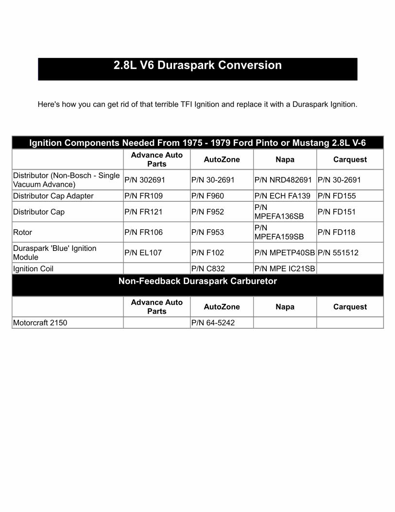
2.8L V6 Duraspark Conversion
Here's how you can get rid of that terrible TFI Ignition and replace it with a Duraspark Ignition.
Ignition Components Needed From 1975 - 1979 Ford Pinto or Mustang 2.8L V-6
Advance Auto Parts AutoZone Napa Carquest
Distributor (Non-Bosch - Single Vacuum Advance) P/N 302691 P/N 30-2691 P/N NRD482691 P/N 30-2691
Distributor Cap Adapter P/N FR109 P/N F960 P/N ECH FA139 P/N FD155
Distributor Cap P/N FR121 P/N F952 P/N MPEFA136SB P/N FD151
Rotor P/N FR106 P/N F953 P/N MPEFA159SB P/N FD118
Duraspark 'Blue' Ignition Module P/N EL107 P/N F102 P/N MPETP40SB P/N 551512
Ignition Coil P/N C832 P/N MPE IC21SB
Non-Feedback Duraspark Carburetor
Advance Auto Parts AutoZone Napa Carquest
Motorcraft 2150 P/N 64-5242
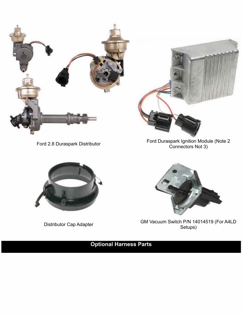
Ford 2.8 Duraspark Distributor Ford Duraspark Ignition Module (Note 2 Connectors Not 3)
Distributor Cap Adapter GM Vacuum Switch P/N 14014519 (For A4LD Setups)
Optional Harness Parts
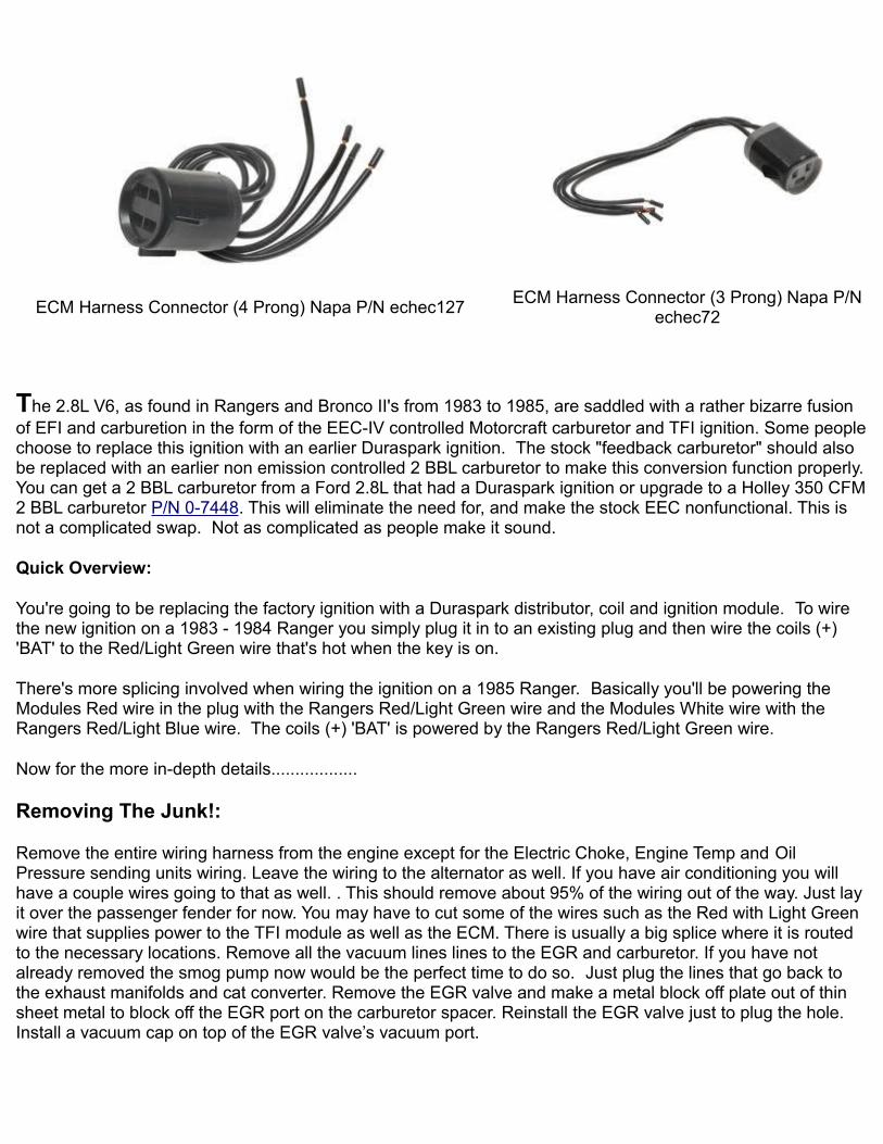
ECM Harness Connector (4 Prong) Napa P/N echec127 ECM Harness Connector (3 Prong) Napa P/N echec72
The 2.8L V6, as found in Rangers and Bronco II's from 1983 to 1985, are saddled with a rather bizarre fusion of EFI and carburetion in the form of the EEC-IV controlled Motorcraft carburetor and TFI ignition. Some people choose to replace this ignition with an earlier Duraspark ignition. The stock "feedback carburetor" should also be replaced with an earlier non emission controlled 2 BBL carburetor to make this conversion function properly. You can get a 2 BBL carburetor from a Ford 2.8L that had a Duraspark ignition or upgrade to a Holley 350 CFM 2 BBL carburetor P/N 0-7448. This will eliminate the need for, and make the stock EEC nonfunctional. This is not a complicated swap. Not as complicated as people make it sound.
Quick Overview:
You're going to be replacing the factory ignition with a Duraspark distributor, coil and ignition module. To wire the new ignition on a 1983 - 1984 Ranger you simply plug it in to an existing plug and then wire the coils (+) 'BAT' to the Red/Light Green wire that's hot when the key is on.
There's more splicing involved when wiring the ignition on a 1985 Ranger. Basically you'll be powering the Modules Red wire in the plug with the Rangers Red/Light Green wire and the Modules White wire with the Rangers Red/Light Blue wire. The coils (+) 'BAT' is powered by the Rangers Red/Light Green wire.
Now for the more in-depth details..................
Removing The Junk!:
Remove the entire wiring harness from the engine except for the Electric Choke, Engine Temp and Oil Pressure sending units wiring. Leave the wiring to the alternator as well. If you have air conditioning you will have a couple wires going to that as well. . This should remove about 95% of the wiring out of the way. Just lay it over the passenger fender for now. You may have to cut some of the wires such as the Red with Light Green wire that supplies power to the TFI module as well as the ECM. There is usually a big splice where it is routed to the necessary locations. Remove all the vacuum lines lines to the EGR and carburetor. If you have not already removed the smog pump now would be the perfect time to do so. Just plug the lines that go back to the exhaust manifolds and cat converter. Remove the EGR valve and make a metal block off plate out of thin sheet metal to block off the EGR port on the carburetor spacer. Reinstall the EGR valve just to plug the hole. Install a vacuum cap on top of the EGR valve’s vacuum port.

Remove the plug wires and cap from the distributor. Bump the starter to get cylinder #1 at top dead center. Unplug the TFI connector from the distributor. Remove the distributor by removing the 13mm hold down bolt on the back of the intake manifold. Gently pull out the distributor.
Assemble the new distributor by screwing on the rotor and install the distributor cap collar. Make sure to grease the O-ring on the new distributor before sliding it in. Slide in the distributor making sure to keep the rotor pointed at the #1 piston. If it will not slide all the way down try turning the crankshaft with a ratchet just a bit and it should engage with the cam gear then. Reinstall the distributor hold down bracket and bolt but don’t tighten yet.
Mount The Duraspark Ignition Module:
Find a suitable place to mount the Duraspark box on the drivers side fender. Connect the wiring harness you got from the donor vehicle to the distributor and route it over to the Duraspark box and connect it up. The distributor end has (4) pins and the Duraspark end has (3) as the green wire goes to the (–) side of the coil.
Power to the Duraspark Module 1983 - 1984 Ranger / Bronco II ('Plug-n-Play'):
If you have a 1983 or 1984 Ranger/Bronco II you're in luck. There is a factory round Duraspark style plug with Red and White wires at the drivers fender well. It will plug in to the plug with White and Red wires on the Duraspark Ignition Module. Don't be alarmed when you notice that a Red wire plugs into a White one and vice versa. This is correct.
The (+) 'BAT' side of the Coil is the only place you have to splice into a wire. On the driver's fender well, there is another connector, square in shape and gray in color that has either a Brown wire with Pink markings or a Red wire with Light Green. These wires should be hot when the key is on. This wire needs to go to the (+) 'BAT' terminal on the ignition coil.
Power to the Duraspark Module 1985 Ranger / Bronco II:
Many found, that after installing the module, distributor, harness, and coil, that the plug with the Red wire and the Light Green wire on the 1985 Ranger that connects to the Red and White wires on the Duraspark Ignition Module does not supply power to the module like it should. It was also found that without some cutting and splicing, that the engine would also not even turn over. This isn't that difficult to overcome.
Both of the wires (Red & White) in the plug on the Duraspark Ignition Module are both used for power input to the module:
Red wire (Modules 2-wire plug) - This wire needs power when the Key is ON.
White wire (Modules 2-wire plug) - This wire needs power from the key in the START position.
Plugs to look for:
There are two round Duraspark style plugs at the drivers fender well:
Plug #1) 2-Wire Duraspark type female round plug with a Red/Light Blue wire and Light Green wire going in. The Red/Light Blue wire has power in the START position.

Plug #2) 4-Wire Duraspark type female round plug. The 4-wires are:
2 - Purple/Orange wires - Power to the back-up lamp switch.
1 - Red/Light Blue Stripe wire - Part of cranking circuit with key in START position.
1 - Dark Blue wire - No longer used
Plug #3) Gray rectangle plug with a Red/Light Green wire. The Red/Light Green wire has power in the START & RUN position.
Connections to make:
1) Cut the Light Green wire going in the Duraspark style 2-wire plug (#1 Above) with enough room to wire on to it. Tape off the other end. Find the Red/Light Green wire in the gray rectangle plug (#3) above. Splice the Light Green wire in plug #1 above in to this Red/Light Green wire. When the plug is connected to the Duraspark Ignition Module, it will line up with the Red wire in the Modules plug to supply power when the key is ON.
2) Run a wire from the Red/Light Green wire to the (+) 'BAT' side of the Ignition Coil to supply power when the key is ON.
3) The 2-wire plug (#1) and 4-wire plug (#2) above have Red/Light Blue wires and need to be spliced together. They are part of the cranking circuit. Without splicing the two Red/Light Blue wires together, the engine's starter will not operate. The Red/Light Blue wire in the plug when connected to the Duraspark Ignition Module will line up with the White wire in the Modules plug to supply a signal when in the START position.
Connecting the Distributor:
Your distributor has an Orange/Yellow, Purple/Light Blue & Black/Light Green wire coming off of it.
Your Duraspark Ignition Module has an Orange/Yellow, Purple/Light Blue, Black/Light Green, and Dark Green/Yellow wire coming off of it.
You can go to a salvage yard and pick up a wire harness from a late 70's or very early '80 Ford car/truck with the Duraspark ignition to run between the Distributor and the Ignition Module. Your other option is to simply make your own harness with 12ga wire and female connectors and match the plugs up color to color.
Note that the Ignition Module has a Dark Green/Yellow wire that the Distributor does not. The Dark Green wire connects to the (-) 'TACH' side of the Ignition Coil.
Finally:
Hook up a vacuum line from the distributor to the carburetor above the carburetor plates to get ported vacuum not at the back of the carburetor or on the intake manifold vacuum tree. Plug the vacuum port on the front of the intake under the carburetor if you are not using the Motorcraft 2150 carburetor.
Install the distributor cap and connect the plug wires. Now fire it up and set the timing. Then tighten the

distributor hold down bolt and you are done.
Using The A4LD Transmission With This Conversion:
The A4LD automatic overdrive transmission is a Ford C3 automatic transmission modified with the addition of overdrive. The first version of this transmission has a single electronic control solenoid located in the valve body that moves a valve allowing transmission fluid to flow into the TCC (torque converter clutch) circuit of the transmission. When fluid flows through this circuit it causes the engagement of the TCC. This process is known as "converter lockup". The timing of this lockup is controlled by the ECA (Electronic Control Assembly). The purpose of the clutch is to create a direct positive connection between the engine and transmission. This reduces slippage, thereby limiting the workload on the engine which improves power transmission to the driveline, and fuel economy. Normally the clutch should only engage at a steady highway speed (approximately 45+ MPH) with the transmission shifted into overdrive.
The later models incorporated electronically controlled overdrive as well. This was achieved with the addition of one or more control solenoids for this process.
Ford only offered the first version of this transmission for 2.8L powered Rangers and Bronco II's in 1984, and 1985. In 1986 the OD position on the shift selector was removed, and replaced with an electronic OD shift button. Vehicles equipped with the early version of this transmission require additional steps to complete the Duraspark conversion.
Toggle Switch Method:
It could be possible to control the converter lock up with a toggle switch. The only drawback is you have to judge the correct time to engage it and disengage it yourself. The control solenoid is similar to a relay switch. It is controlled by two wires, positive and negative. The positive wire receives a constant 12V. The negative wire is a controlled ground. This means that with a functional ECA, the computer uses a switching circuit to connect and disconnect the ground. This completes, or breaks the circuit. If you'd like to try the "Toggle Switch Method" this method this is how to do it.
Locate the solenoid connector on the transmission toward the drivers side front on the top of the pan lip
Unplug it and using a test light find the 12V power lead. Now you know the other wire is the ground.
Cut the ground wire about 4" back from the connector. On the connectors side, strip the jacket on the ground wire about 1/2" back. Plug the connector back in and ground the wire you just stripped to the transmission. If you here a click then you know that the solenoid is functional. Unplug the connector again.
Using a length of 16AWG wire long enough to reach into the vehicles passenger compartment butt connect this wire to the ground wire using a 16AWG butt connector. Plug the connector back in.
Route the wire up into the passenger compartment near a suitable switch mounting location. Connect the wire to one terminal of a SPST (Single Pole Single Throw) 12V toggle switch. Using a short piece of 16AWG wire connect one end to the other switch terminal and the remaining end to a good ground. Mount the switch and test it out.
Pressure Switch Method:

The second method we have for you utilizes a pressure switch. This is an automatic engagement solution. The pressure switch is installed in the governor portion of the transmission body. When the fluid pressure reaches the switch tolerance the switch closes completing the circuit and energizing the solenoid. This should occur at highway speeds (45+ MPH) when shifted into overdrive
Use the same instructions in the above procedure to determine which wire is the controlled ground.
1) On the passenger side of the transmission toward the back at the bottom near the tail extension locate a protrusion with a hole in the center which resembles a bolt boss. This is the governor area of the transmission. Using a 3/16" drill bit coated with grease to collect shavings carefully drill in the center of this hole until it punches through into the internal chamber
2) Start the engine and let it run for about a few seconds which will force out any remaining shavings (transmission fluid will stream out forcing the remaining debris out).
3) Using an 1/8" pipe thread tap, tap threads into the boss about 1/2" deep. It may be necessary to open up the hole a little prior to tapping. Use the size drill bit recommended on the tap. Run the engine again to force out remaining debris.
4) Thread in a 44-52 PSI pressure switch into the hole
5) Run a hot wire to one side of the transmission plug and the other wire to the controlled ground pressure switch. Drive the vehicle and once you reach highway speed (45+MPH) shift into overdrive and pay close attention to the feel of the shift. If it feels firm and you don't experience erratic "in and out" OD shifting then you were successful. If it does shift "in and out" erratically you may need to experiment with different tolerance pressure switches until you find what works best for you
You can also see this article HERE.
Performance Automotive and Transmission Center sells the pressure switch P/N A4LDPS HERE.
Vacuum Switch:
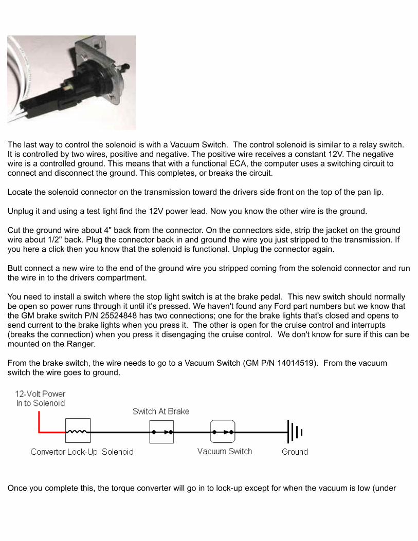
The last way to control the solenoid is with a Vacuum Switch. The control solenoid is similar to a relay switch. It is controlled by two wires, positive and negative. The positive wire receives a constant 12V. The negative wire is a controlled ground. This means that with a functional ECA, the computer uses a switching circuit to connect and disconnect the ground. This completes, or breaks the circuit.
Locate the solenoid connector on the transmission toward the drivers side front on the top of the pan lip.
Unplug it and using a test light find the 12V power lead. Now you know the other wire is the ground.
Cut the ground wire about 4" back from the connector. On the connectors side, strip the jacket on the ground wire about 1/2" back. Plug the connector back in and ground the wire you just stripped to the transmission. If you here a click then you know that the solenoid is functional. Unplug the connector again.
Butt connect a new wire to the end of the ground wire you stripped coming from the solenoid connector and run the wire in to the drivers compartment.
You need to install a switch where the stop light switch is at the brake pedal. This new switch should normally be open so power runs through it until it's pressed. We haven't found any Ford part numbers but we know that the GM brake switch P/N 25524848 has two connections; one for the brake lights that's closed and opens to send current to the brake lights when you press it. The other is open for the cruise control and interrupts (breaks the connection) when you press it disengaging the cruise control. We don't know for sure if this can be mounted on the Ranger.
From the brake switch, the wire needs to go to a Vacuum Switch (GM P/N 14014519). From the vacuum switch the wire goes to ground.
Once you complete this, the torque converter will go in to lock-up except for when the vacuum is low (under

throttle) or when the brakes are applied.
You can find the GM Vacuum Switch P/N 14014519 at http://www.gmpartsdirect.com/
Parts stores supposedly carry this part but we don't have the part numbers for them yet. Give them the GM P/N and see if they can look it up.
Rock Auto carries them under the STANDARD MOTOR PRODUCTS line P/N VX2 (LOCK-UP TORQUE CONVERTER SWITCH). Do a search at http://www.rockauto.com
Performance Automotive and Transmission Center sells vacuum switches including adjustable vacuum switches on This Page.
Thanks To:
'Totalled-E.B.BII'
James Pringle
'Budro'
For their contributions to this page over time.
Diagrams:
1983 - 1988 Ford Ranger Ignition Diagrams #1
1985 Ford Ranger Ignition Diagram #2 (PDF)
1979 Ford Duraspark Ignition Diagrams (PDF)
Typical Duraspark Ignition


1984 Bronco II vaccum hose diagram
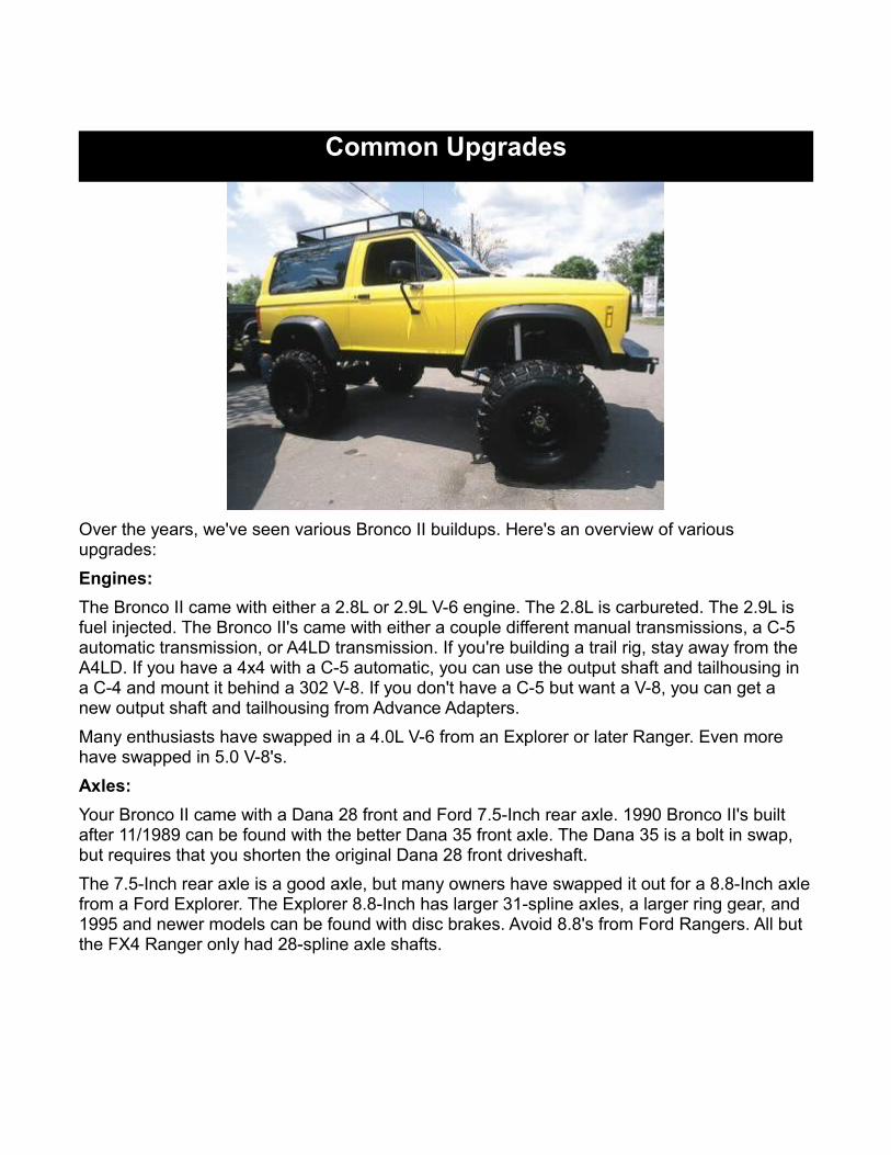
Common Upgrades
Over the years, we've seen various Bronco II buildups. Here's an overview of various upgrades:Engines:The Bronco II came with either a 2.8L or 2.9L V-6 engine. The 2.8L is carbureted. The 2.9L is fuel injected. The Bronco II's came with either a couple different manual transmissions, a C-5 automatic transmission, or A4LD transmission. If you're building a trail rig, stay away from the A4LD. If you have a 4x4 with a C-5 automatic, you can use the output shaft and tailhousing in a C-4 and mount it behind a 302 V-8. If you don't have a C-5 but want a V-8, you can get a new output shaft and tailhousing from Advance Adapters.Many enthusiasts have swapped in a 4.0L V-6 from an Explorer or later Ranger. Even more have swapped in 5.0 V-8's.Axles:Your Bronco II came with a Dana 28 front and Ford 7.5-Inch rear axle. 1990 Bronco II's built after 11/1989 can be found with the better Dana 35 front axle. The Dana 35 is a bolt in swap, but requires that you shorten the original Dana 28 front driveshaft. The 7.5-Inch rear axle is a good axle, but many owners have swapped it out for a 8.8-Inch axle from a Ford Explorer. The Explorer 8.8-Inch has larger 31-spline axles, a larger ring gear, and 1995 and newer models can be found with disc brakes. Avoid 8.8's from Ford Rangers. All but the FX4 Ranger only had 28-spline axle shafts.

Ford 8.8-Inch Rear Axle With Discs (Shown Upside Down)Some enthusiasts have swapped in a Dana 44 in place of the stock front TTB axle.
An upgrade that's gaining in popularity is a Dana 44 steering knuckle swap on to a Dana 35. You'll have 1/2 ton outers meaning you have better hubs, wheel bearing spacing, larger rotors and calipers then on the Dana 35. Shaft wise you have a stronger shaft assemble then a Dana 44. The only shaft of a Dana 35 that has a smaller diameter then that of the neck on Dana 44 shafts is the stub shaft. By running Dana 44 stubs you eliminate this. Granted the Dana 35 shafts taper down to 27-spline that goes into the side gears but this minor diameter is still greater then that of the neck on a Dana 44. And as we all know a chain is only as strong as the weakest link, the weak link of a Dana 44 being the neck.We've also seen Bronco II's with custom suspensions and axles as large as 2.5-Ton Rockwell military axles.Suspension:The factory TTB front suspension can be built for quite a bit of suspension travel using extended radius arms with longer shocks and taller shock mounts. Kit's like this Skyjacker kit offers new front and rear springs, heavy duty suspension brackets and extended radius arms for more wheel travel.
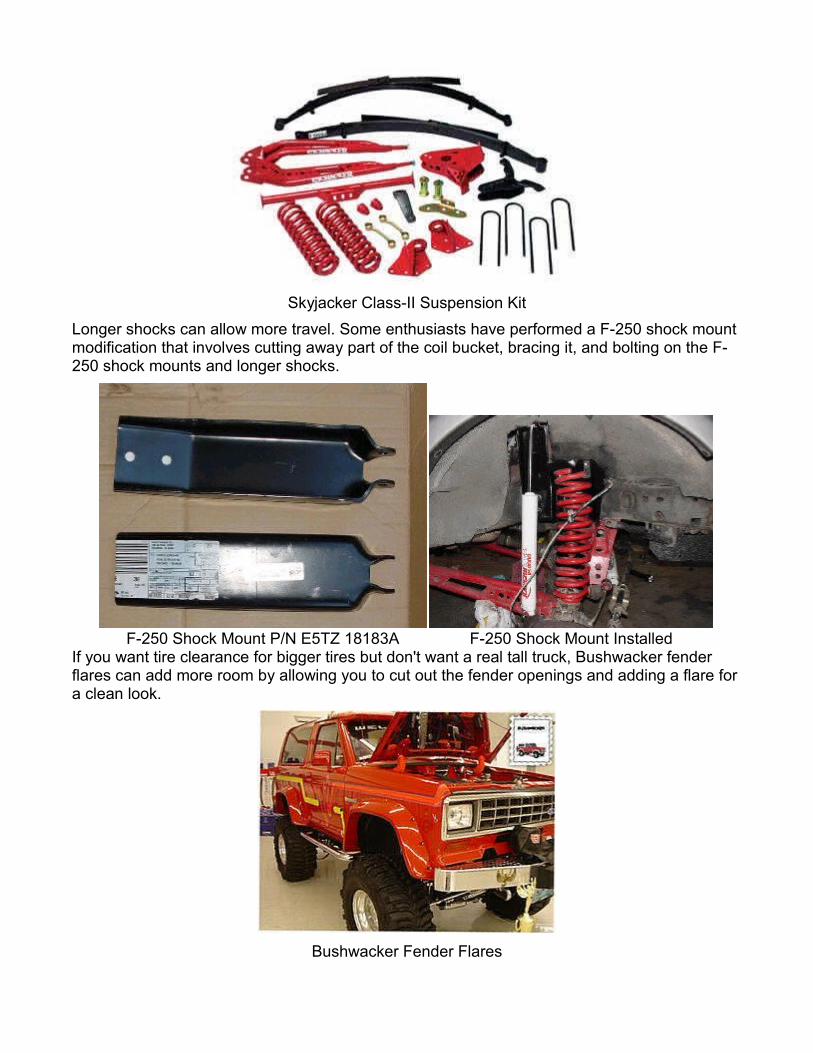
Skyjacker Class-II Suspension KitLonger shocks can allow more travel. Some enthusiasts have performed a F-250 shock mount modification that involves cutting away part of the coil bucket, bracing it, and bolting on the F-250 shock mounts and longer shocks.
F-250 Shock Mount P/N E5TZ 18183A F-250 Shock Mount InstalledIf you want tire clearance for bigger tires but don't want a real tall truck, Bushwacker fender flares can add more room by allowing you to cut out the fender openings and adding a flare for a clean look.
Bushwacker Fender Flares

Tire Fitment:The chart below will give you a guide as to what size tires will fit based on the amount of lift you have. The chart reads from left to right.
Ford Bronco II Tire SizeLift Height 30-Inches 31-Inches 32-Inches 33-Inches 35-Inches
2-Inches Fender Trimming
3-Inch Body Lift
3-Inch Body Lift And Fender
Trimming
N/A N/A
4-Inches OK OK Fender Trimming
3-Inch Body Lift
3-Inch Body Lift And Fender
Trimming
6-Inches OK OK OK OK 3-Inch Body Lift
Note: 35-Inch tires will fit on a Bronco II with a 6-inch suspension lift and Bushwacker Cut Out fender flares.Chop Top:You'll find a bunch of enthusiasts that have chopped the top of their Bronco II's off behind the front doors. You can put in a Ranger tailgate to fill in the rear once the factory hatch is gone.
Where To Find The Info:Visit the Technical Library at The Ranger Station HERE. You'll find information on the modifications mentioned above and a whole bunch more.
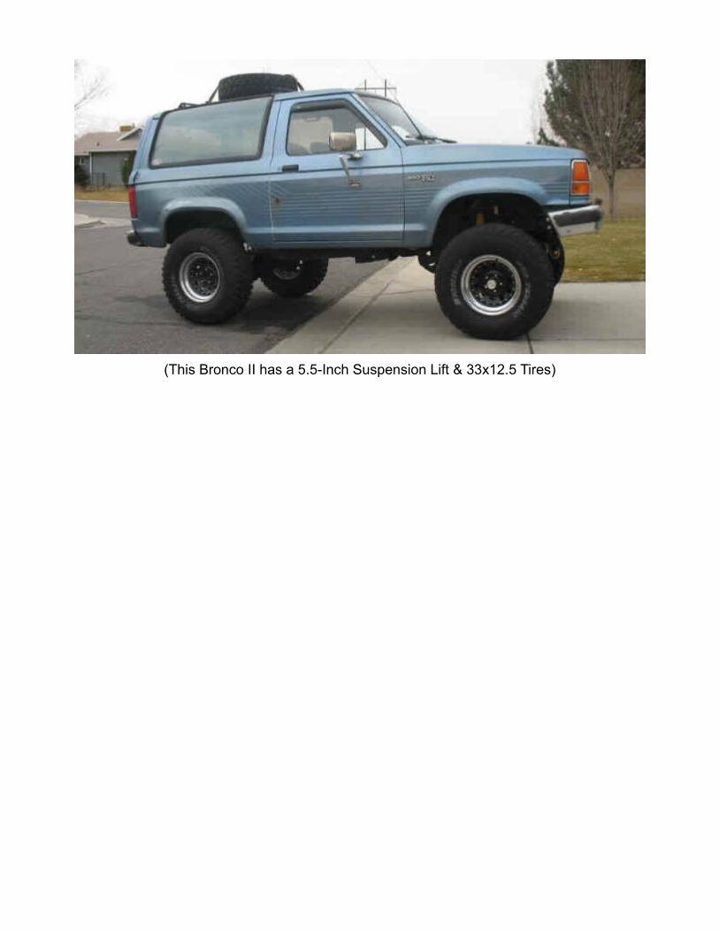
(This Bronco II has a 5.5-Inch Suspension Lift & 33x12.5 Tires)
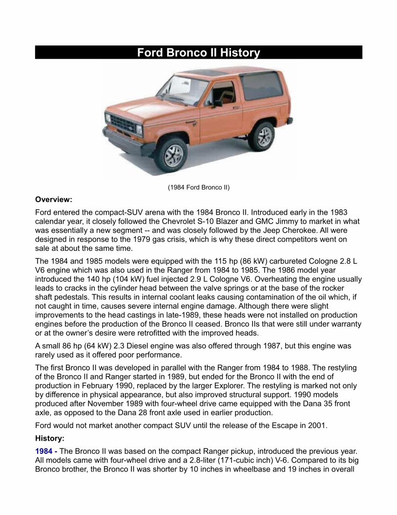
Ford Bronco II History
(1984 Ford Bronco II)
Overview:Ford entered the compact-SUV arena with the 1984 Bronco II. Introduced early in the 1983 calendar year, it closely followed the Chevrolet S-10 Blazer and GMC Jimmy to market in what was essentially a new segment -- and was closely followed by the Jeep Cherokee. All were designed in response to the 1979 gas crisis, which is why these direct competitors went on sale at about the same time.The 1984 and 1985 models were equipped with the 115 hp (86 kW) carbureted Cologne 2.8 L V6 engine which was also used in the Ranger from 1984 to 1985. The 1986 model year introduced the 140 hp (104 kW) fuel injected 2.9 L Cologne V6. Overheating the engine usually leads to cracks in the cylinder head between the valve springs or at the base of the rocker shaft pedestals. This results in internal coolant leaks causing contamination of the oil which, if not caught in time, causes severe internal engine damage. Although there were slight improvements to the head castings in late-1989, these heads were not installed on production engines before the production of the Bronco II ceased. Bronco IIs that were still under warranty or at the owner’s desire were retrofitted with the improved heads.A small 86 hp (64 kW) 2.3 Diesel engine was also offered through 1987, but this engine was rarely used as it offered poor performance.The first Bronco II was developed in parallel with the Ranger from 1984 to 1988. The restyling of the Bronco II and Ranger started in 1989, but ended for the Bronco II with the end of production in February 1990, replaced by the larger Explorer. The restyling is marked not only by difference in physical appearance, but also improved structural support. 1990 models produced after November 1989 with four-wheel drive came equipped with the Dana 35 front axle, as opposed to the Dana 28 front axle used in earlier production.Ford would not market another compact SUV until the release of the Escape in 2001.History:1984 - The Bronco II was based on the compact Ranger pickup, introduced the previous year. All models came with four-wheel drive and a 2.8-liter (171-cubic inch) V-6. Compared to its big Bronco brother, the Bronco II was shorter by 10 inches in wheelbase and 19 inches in overall

length, and -- most significantly -- lighter by more than 800 lbs. A sporty XLS package added tri-color tape stripes and wheelwell "spats."
(1985 Ford Bronco II)
1985 - Aside from a five-speed manual transmission replacing a four-speed as standard, and the newly available four-speed automatic as an option, Bronco II saw few changes for 1985. It could look quite ritzy when dressed up with optional decor packages.1986 - Newly available in 1986 was a new fuel-injected 2.9-liter V-6 engine. Also offered that year -- but rarely ordered -- was a 2.3-liter turbodiesel. Four-wheel-drive Bronco II's got a new "shift-on-the-fly" system in 1986. A non-four-wheel-drive (2wd) version was now offered for the Bronco II.1987 - No real changes. The Bronco II got rear-wheel anti-lock brakes.
The 1989 Bronco II shared the Ford Ranger's restyled front end and interior, but little else was new.

Bronco II was in its swan-song year, and was thus carried over with few changes.Toward the end of the 1990 model year, Ford released a new sport-utility vehicle called the Explorer. It was labeled a 1991 model and would quickly become the best-selling SUV in the U.S. -- a title it has garnered every year since. But it spelled the end of the smaller two-door Bronco II, which had amassed its own devoted following with its tidy size and reasonable fuel efficiency.Special Editions:
From 1987-1989 dealers were able to offer a 'Sherrod' Bronco II that came with a removable top. Click HERE for more information.Bronco II's and Rollovers:
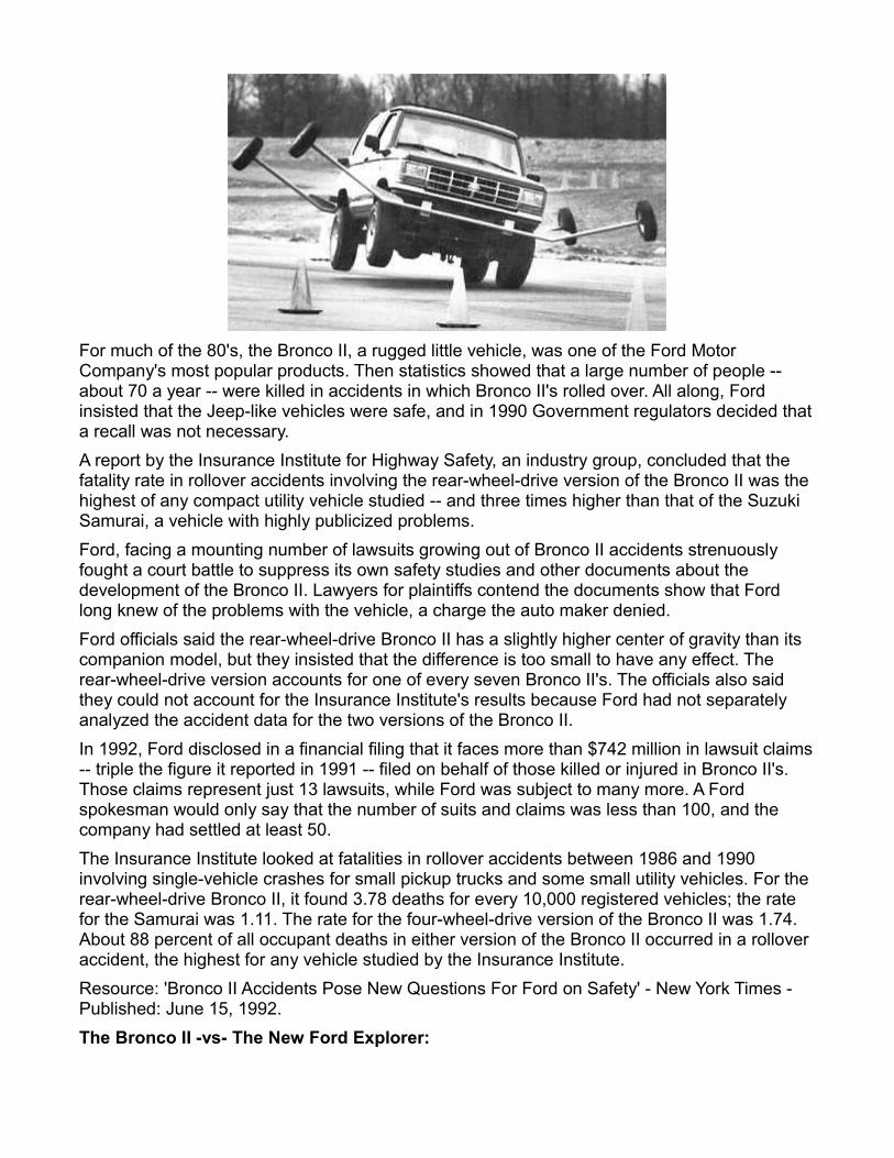
For much of the 80's, the Bronco II, a rugged little vehicle, was one of the Ford Motor Company's most popular products. Then statistics showed that a large number of people -- about 70 a year -- were killed in accidents in which Bronco II's rolled over. All along, Ford insisted that the Jeep-like vehicles were safe, and in 1990 Government regulators decided that a recall was not necessary.A report by the Insurance Institute for Highway Safety, an industry group, concluded that the fatality rate in rollover accidents involving the rear-wheel-drive version of the Bronco II was the highest of any compact utility vehicle studied -- and three times higher than that of the Suzuki Samurai, a vehicle with highly publicized problems.Ford, facing a mounting number of lawsuits growing out of Bronco II accidents strenuously fought a court battle to suppress its own safety studies and other documents about the development of the Bronco II. Lawyers for plaintiffs contend the documents show that Ford long knew of the problems with the vehicle, a charge the auto maker denied.Ford officials said the rear-wheel-drive Bronco II has a slightly higher center of gravity than its companion model, but they insisted that the difference is too small to have any effect. The rear-wheel-drive version accounts for one of every seven Bronco II's. The officials also said they could not account for the Insurance Institute's results because Ford had not separately analyzed the accident data for the two versions of the Bronco II.In 1992, Ford disclosed in a financial filing that it faces more than $742 million in lawsuit claims -- triple the figure it reported in 1991 -- filed on behalf of those killed or injured in Bronco II's. Those claims represent just 13 lawsuits, while Ford was subject to many more. A Ford spokesman would only say that the number of suits and claims was less than 100, and the company had settled at least 50.The Insurance Institute looked at fatalities in rollover accidents between 1986 and 1990 involving single-vehicle crashes for small pickup trucks and some small utility vehicles. For the rear-wheel-drive Bronco II, it found 3.78 deaths for every 10,000 registered vehicles; the rate for the Samurai was 1.11. The rate for the four-wheel-drive version of the Bronco II was 1.74. About 88 percent of all occupant deaths in either version of the Bronco II occurred in a rollover accident, the highest for any vehicle studied by the Insurance Institute. Resource: 'Bronco II Accidents Pose New Questions For Ford on Safety' - New York Times - Published: June 15, 1992.The Bronco II -vs- The New Ford Explorer:

The Bronco II was designed and marketed for use on both roadways and on rugged backroads. It is boxy with a high center of gravity because its wheels are set close together and its chassis is high off the ground to clear obstacles. Federal officials say such designs make many compact utility vehicles more prone to roll over than passenger cars.Perhaps this was the influence behind Ford's release of the longer wheel base Ford Explorer in 1990 and the end of the Bronco II that same year.Strange Fact:All Ford Bronco II's had four-wheel-drive transfer cases. Even the two-wheel-drive models. Why? Who knows. The BW1359 transfer case in the two-wheel-drive Bronco II's was basically a 'dummy' case and had a permanent seal where the front driveshaft would go. This means that the two-wheel-drive Bronco II's had four-wheel-drive transmissions. It's strange considering the Ranger and Bronco II drivetrain was essentially the same. Why didn't Bronco II's have a Ranger two-wheel-drive transmission with a longer drivershaft?