british columbia construction craft worker apprenticeship ... · british columbia construction...
TRANSCRIPT

British Columbia
CONSTRUCTION CRAFT WORKERAPPRENTICESHIP PROGRAM
Local 1611
LINE I: Perform Utilities and Pipeline TasksPerform Utilities and Pipeline Tasks
LEVEL 1


CONSTRUCTION CRAFT WORKER APPRENTICESHIP PROGRAMLEVEL 1
Line I: Perform Utilities and Pipeline Tasks

Acknowledgements & Copyright Permission© 2017 Industry Training Authority
This publication may not be reproduced in any form without written permission by the Industry Training Authority.
Version 1 January 2017
The Industry Training Authority is under a licensing agreement with LiUNA (Labourers International Union of North American) Local 1611 to use their Construction Craft Workers Level 1 and Level 2 training materials throughout British Columbia and Canada. The Industry Training Authority would like to thank LiUNA for making these materials available.
Construction and Specialized Workers Training SocietyThese materials were initially developed for the first classes of Apprenticeship.
Level 1 by the Construction and Specialized Workers Training Society (CSWTS) in January of 2015 (British Columbia).
Those originally responsible for the manual:
• Manuel Alvernaz; Chairman of the Construction and Specialized Workers Training Society (CSWTS)
• Fred Webber; PID, Red Seal Journeyperson, Administrator and Senior Instructor (CSWTS)
• Tom Miller; PID, Red Seal Journeyperson, instructor (CSWTS)
• Jeffrey Anders; BSc, BA, Red Seal Journeyperson, Special International and Trifunds Representative (LIUNA)
Open School BCSolvig Norman, Project Manager Monique Brewer, DirectorJennifer Riddel, Manager of Instructional ServicesDennis Evans, Production Technician (print layout, image researcher, photographer & illustrations)Max Licht, IllustratorAndrei Antica, photographerShannon Sangster, Office Manager (copyright permissions)
Copyright Permission“Directional drilling” with permission by Vermeer Corp.Wikimedia Commons: Tapping water line in Bentonville, AR.jpg - Author: BrandonrushSome images were licensed from Thinkstock.

CONSTRUCTION CRAFT WORKER APPRENTICESHIP PROGRAM—LEVEL 1 3
ContentsForeword . . . . . . . . . . . . . . . . . . . . . . . . . . . . . . . . . . . . . . . . . . . . . . . . . . . . 5Program Outline . . . . . . . . . . . . . . . . . . . . . . . . . . . . . . . . . . . . . . . . . . . . . . . . 5
Competency I1: Install Utility Piping . . . . . . . . . . . . . . . . . . . . . . . . . . . . . . . . . . . . . . 7Water systems . . . . . . . . . . . . . . . . . . . . . . . . . . . . . . . . . . . . . . . . . . . . . . . . . 7Sewer systems . . . . . . . . . . . . . . . . . . . . . . . . . . . . . . . . . . . . . . . . . . . . . . . . 12Installation . . . . . . . . . . . . . . . . . . . . . . . . . . . . . . . . . . . . . . . . . . . . . . . . . . 15Utility components . . . . . . . . . . . . . . . . . . . . . . . . . . . . . . . . . . . . . . . . . . . . . 17Manhole construction . . . . . . . . . . . . . . . . . . . . . . . . . . . . . . . . . . . . . . . . . . . 20Leveling and altering utility components . . . . . . . . . . . . . . . . . . . . . . . . . . . . . . . 22

4 CONSTRUCTION CRAFT WORKER APPRENTICESHIP PROGRAM—LEVEL 1
DisclaimerThe materials in these Learning Guides are for use by students and instructional staff, and have been compiled from sources believed to be reliable and to represent best current opinions on these subjects. These manuals are intended to serve as a starting point for good practices and may not specify all minimum legal standards. No warranty, guarantee or representation is made by the British Columbia Industry Training Authority or the Queen’s Printer of British Columbia as to the accuracy or sufficiency of the information contained in these publications. These manuals are intended to provide basic guidelines for Construction Craft Worker practices. Do not assume, therefore, that all necessary warnings and safety precautionary measures are contained in this Competency and that other or additional measures may not be required.
Safety AdvisoryBe advised that references to the Workers’ Compensation Board of British Columbia safety regulations contained within these materials do not/may not reflect the most recent Occupational Health and Safety Regulation. The current Standards and Regulation in BC can be obtained at the following website: http://www.worksafebc.com.
Symbol Legend
Important: This icon highlights important information.
Poisonous: This icon is a reminder for a potentially toxic/poisonous situation.
Resources: The resource icon highlights any required or optional resources.
Flammable: This icon is a reminder for a potentially flammable situation.
Self-test: This icon reminds you to complete a self-test.
Explosive: This icon is a reminder for a possibly explosive situation.
Safety gear: The safety gear icon is an important reminder to use protective equipment.
Electric shock: This icon is a reminder for potential electric shock.

CONSTRUCTION CRAFT WORKER APPRENTICESHIP PROGRAM—LEVEL 1 5
ForewordConstruction Craft Workers, also known as labourers, work mostly on construction sites. Their tasks include:
• Site preparation and cleanup.• Set up and remove access equipment.• Work on concrete and masonry, steel, wood and pre-cast erecting projects.• Handle materials and equipment• Perform demolition, excavation, and compaction activities.• Ensure site security.
Construction Craft Workers (CCWs) work on a wide variety of structures such as residential, commercial and industrial buildings, as well as hydro-electric dams, roadways, bridges and railways. In some jurisdictions, they also work on utility, landscape, and pipeline projects. CCWs work for private companies as well as municipal, provincial, and federal governments.
With experience, CCWs who complete additional training specialize in different areas of construction. This includes operating off-road vehicles, drilling and blasting, diving, tunneling, rock scaling, performing emergency rescue, and the management of pedestrian and vehicular traffic in situations involving potential hazards and public trust.
CCWs work primarily outdoors in all weather conditions. They are often required to work at heights, over water, in confined spaces, and excavations. Their job settings are in densely populated urban settings or in remote locations. They often work overtime during peak construction periods.
Key attributes for CCWs are mechanical aptitude, manual dexterity and an ability to do hard, physical work. They must also be able to work as team members and to interact directly with the public where such considerations as safety and legal liability are issues. Organizational leadership and blueprint reading skills are assets for anyone wanting to progress in this trade. With experience and training, CCWs can advance to supervisory/foreman positions.
Program OutlineLevel 1Line A: Use Safe Work PracticesLine B: Organize WorkLine C: Use Tools and EquipmentLine D: Perform Routine Trade ActivitiesLine E: Perform Site WorkLine F: Use Scaffolding and Access EquipmentLine G: Perform Concrete WorkLine I: Perform Utilities and Pipeline TasksLine J: Perform Roadwork
Level 2Line A: Use Safe Work PracticesLine B: Organize WorkLine D: Perform Routine Trade ActivitiesLine E: Perform Site WorkLine F: Use Scaffolding and Access EquipmentLine G: Perform Concrete WorkLine H: Perform Masonry WorkLine I: Perform Utilities and Pipeline Tasks

6 CONSTRUCTION CRAFT WORKER APPRENTICESHIP PROGRAM—LEVEL 1

CONSTRUCTION CRAFT WORKER APPRENTICESHIP PROGRAM—LEVEL 1 7
COMPETENCy I1 LINE I: PERFORM UTILITIES ANd PIPELINE TASKS
COMPETENCY I1
Install Utility PipingInstalling utility piping can be hazardous. Wearing the correct PPE including steel-toed boots, hearing protection, eye protection, safety vest, hard hat and gloves is important. For example, workers must be aware of the high noise volume from heavy equipment and pinch points on equipment and materials.
Individual pipes and loads of pipes are rigged or carried into the ditch using excavators and side booms. Suspended pipe can be hazardous and accidents can result in serious injury or death. Pipes must be rigged safely using proper rigging equipment with taglines by competent and trained workers.
There are many possible pinch points when installing utility piping. There are pinch points in the rigging materials, on and around heavy equipment and when joining pipe. Workers must be aware and steer clear of possible pinch points.
Whenever digging near pressurized lines, installing additions to existing pressurized lines, or charging water lines, the water pressure in the lines is hazardous. If fittings or joints are not fastened properly, workers can be seriously injured. Always make sure when repairing or installing additions to existing lines that the lines have been de-energized.
Water systemsWater systems deliver potable water to residential and commercial buildings using pressurized water. Various materials are used for water systems. Ductile iron is used for pressurized water and sewer systems. It is stronger, more corrosion resistant, and able to withstand greater loads than standard cast iron pipe. It is particularly suited for deep cuts, high temperatures, and abrasive flows and has a life expectancy of 75 years.
Figure 1 — Ductile iron piping

8 CONSTRUCTION CRAFT WORKER APPRENTICESHIP PROGRAM—LEVEL 1
LINE I: PERFORM UTILITIES ANd PIPELINE TASKS COMPETENCy I1
Plastic pipingPlastic pipe is used for both water mains and water services to individual lots. PVC pipe (blue brute) is a thick walled pipe often used on water mains and thinner plastic pipe (tough tube) is used for water services. Plastic pipe is easy to install, cost-effective, and has a 50 year life expectancy.
Figure 2 — Plastic piping
There are different methods for assembling water piping. Pressurized water mains burst, or leak if not constructed properly. One method for assembling water mains is by connecting bell and spigots. Sections of pipe are connected by inserting the straight spigot end of one section into the bell or flared-out section of another pipe. It is important that the end of each pipe remain clean and that the rubber gaskets in the bell of each pipe stays perfectly in its groove and clean as well. If the rubber gaskets and the spigots are not clean when connecting the pipe, small voids may occur at the connection causing a leak.
Bell and spigot pipingBell and spigot water mains must be aligned correctly. Deflection or misalignment can cause leaks. When installing bell and spigot water main pipes, Construction craft workers must pay attention to detail and work carefully when installing bell and spigot pipes or they may fail inspection.
Figure 3 — Bell and spigot piping

CONSTRUCTION CRAFT WORKER APPRENTICESHIP PROGRAM—LEVEL 1 9
COMPETENCy I1 LINE I: PERFORM UTILITIES ANd PIPELINE TASKS
Mechanical jointsAnother method of connecting water mains uses mechanical joints. Flanges are connected at each joint and then bolted tightly together. Sometimes mechanical joints are placed at bell and spigot joints. Mechanical joints restrict joints from separating but are more cumbersome and time-consuming to install than regular bell and spigot joints.
Figure 4 — Mechanical joints
PE butt fusion is used to fuse together polyethylene pipe, usually HDPE (High-Density Polyethelene) pipe. It uses a thermo fusion process which simultaneously heats the ends of two pipes or fitting components. until a molten state is attained on each contact surface. When the two ends are hot enough the two surfaces are brought together under controlled pressure for a specific cooling time forming a homogenous fusion joint. This type of joint is resistant to end loads. The reason not all pipes are connected using butt fusion is because the process is much more expensive than using bell and spigot.
Heat element between two pipe ends

10 CONSTRUCTION CRAFT WORKER APPRENTICESHIP PROGRAM—LEVEL 1
LINE I: PERFORM UTILITIES ANd PIPELINE TASKS COMPETENCy I1
Heat element removed and pipe ends pushed together
Figure 5 — PE butt fusion
Grade is also important when installing pressurized water mains. The elevations for pressurized water mains are often based from the finished road elevation. The common depth for placing water mains in BC is 0.9 – 1 m. Water mains need to be deep enough that they are below the frost line or they may fracture. The depth acts as insulation for the pipe. Some water main pipe is insulated to keep the cold out and the water from freezing but it is cheaper to place the water main deep enough that frost does not affect the pipe and the water does not freeze. However, if they are too deep, it is more time consuming to install and repair which increases the cost. The construction crew is responsible for ensuring that pipe is installed at the correct elevations and slope.
Directional drilling is another method of installing utilities. This process drills a hole vertically or horizontally. Then the utility (water main) is pulled back through the drilled hole. This method is used to avoid highway or river disruption or because there are too many existing utilities to try to dig through. It is an effective but expensive method of placing pipe.
Figure 6 — Directional drilling
CONSTRUCTION CRAFT WORKER APPRENTICESHIP PROGRAM—LEVEL 1 11
COMPETENCy I1 LINE I: PERFORM UTILITIES ANd PIPELINE TASKS
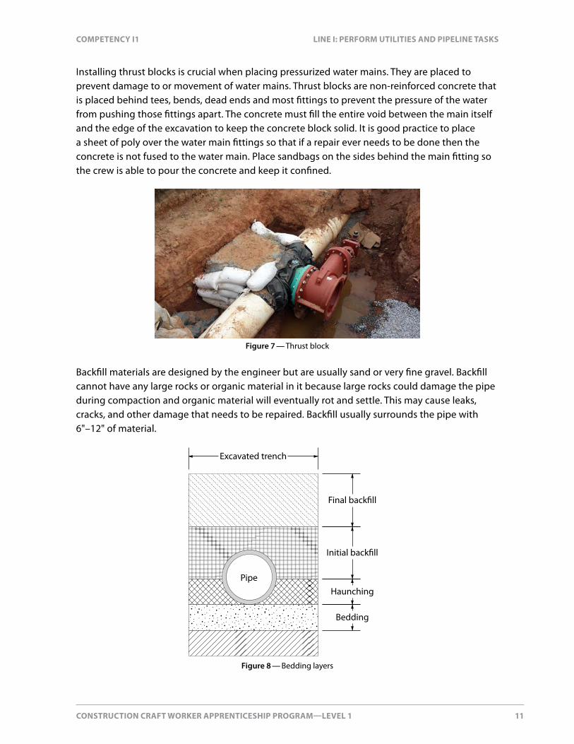
Installing thrust blocks is crucial when placing pressurized water mains. They are placed to prevent damage to or movement of water mains. Thrust blocks are non-reinforced concrete that is placed behind tees, bends, dead ends and most fittings to prevent the pressure of the water from pushing those fittings apart. The concrete must fill the entire void between the main itself and the edge of the excavation to keep the concrete block solid. It is good practice to place a sheet of poly over the water main fittings so that if a repair ever needs to be done then the concrete is not fused to the water main. Place sandbags on the sides behind the main fitting so the crew is able to pour the concrete and keep it confined.
Figure 7 — Thrust block
Backfill materials are designed by the engineer but are usually sand or very fine gravel. Backfill cannot have any large rocks or organic material in it because large rocks could damage the pipe during compaction and organic material will eventually rot and settle. This may cause leaks, cracks, and other damage that needs to be repaired. Backfill usually surrounds the pipe with 6"–12" of material.
Pipe
Excavated trench
Bedding
Haunching
Initial back�ll
Final back�ll
Figure 8 — Bedding layers

12 CONSTRUCTION CRAFT WORKER APPRENTICESHIP PROGRAM—LEVEL 1
LINE I: PERFORM UTILITIES ANd PIPELINE TASKS COMPETENCy I1
Water main systems are made from different components including services, hydrants, tees, bends, and valves. These components must be installed at the correct elevation and location. Sections of pipe are cut so fittings and valves can be installed. After the pipe is installed and backfilled it is pressure tested and chlorinated.
Sewer systemsThere are two types of sewer systems installed underground; storms sewers and sanitary sewers.
Storm sewers drain excess rain and ground water from paved streets, parking lots, paths, sidewalks, and roofs. Storm drain systems consist of catch basins, manholes, main lines and services. Catch basins receive storm water from streets, parking lots, playing fields, etc. Lead pipes connect inlets and catch basins to the main line. These connections are sometimes made at a manhole, but are often hooked directly to the main line pipe. The main line storm drain empties into a river or other natural drainage area.
Since most storm sewer mains use larger pipe, the amount of slope is sometimes very small. Accurate installation is important on slight slopes because a small amount of error in slope leaves areas of standing water in the pipe that may cause deterioration and a buildup of sediment that could lead to clogging.
Figure 9 — Sewer system
Sanitary sewer systems collect and treat sewage in towns and cities. Municipal governments usually operate and maintain the system. A typical sanitary sewer system consists of the main line and the services. Main lines run from manhole to manhole and eventually lead to the treatment facility while services carry the waste from the home or business to the main line. After reaching the treatment facility, the waste is treated with chemicals and then released into the environment.

CONSTRUCTION CRAFT WORKER APPRENTICESHIP PROGRAM—LEVEL 1 13
COMPETENCy I1 LINE I: PERFORM UTILITIES ANd PIPELINE TASKS
Most pipes that carry waste are designed to move the material by gravity flow. This means that the pipe is laid at enough of a slope that the force of gravity moves the material. When this is not possible, a pumping station is used to maintain the flow and force mains are installed.
Positive slope (correct)
Negative slope (low area)
No slope
Figure 10 — Pipe slope
Since sanitary sewers are designed to utilize the force of gravity to keep the material moving, the alignment and gradient (slope) of these pipes is crucial for the system to work properly. Accuracy is essential during installation, and proper construction processes must be followed to ensure that the pipe remains in the originally laid position during backfilling and throughout the life of the system. On a gravity flow system, the bell ends of the pipes must be correctly installed upstream.
Types of pipe used in sewer systems include plastic pipe (PVC and HDPE), reinforced concrete, ductile iron and galvanized steel.
PVC pipe is widely used for storm and sanitary sewers because of its strength, light weight, chemical resistance, low friction properties, and ease of handling. It is manufactured in sizes that range from as small as 0.1 m to as large as 0.9 m. One of the drawbacks of this kind of pipe is that it is not rigid and must be properly bedded to maintain alignment. Typically, once a few joints have been assembled, sand or backfill material is pushed over the pipe to hold it in place. PVC pipe joints are usually joined using rubber gasket push-on type joints.

14 CONSTRUCTION CRAFT WORKER APPRENTICESHIP PROGRAM—LEVEL 1
LINE I: PERFORM UTILITIES ANd PIPELINE TASKS COMPETENCy I1
Rubber seals are used to prevent leakage and ensure a tight seal when connecting PVC pipe. When installing PVC, the rubber seal needs to be lubricated to help slip pipe together and to keep the rubber seal intact.
Figure 11 — PVC pipe rubber seal
HDPE pipe is often used when butt fusion is needed for water mains or sanitary sewers. Butt fusion produces a strong bond between pipes so there is less chance of leaks. HDPE pipe is commonly used for any pressurized mains such as water mains and sanitary force mains but is more expensive than regular PVC pipe for materials and installation.
Reinforced concrete pipe is widely used in storm sewer construction because of its strength and durability. It is available in numerous sizes and strengths. Reinforced concrete pipe can satisfy many job performance requirements but one drawback is that there is a wide range in the both the cost and the performance of gaskets and sealants. Concrete pipe does not usually have an air tight seal, so some infiltration of groundwater or exfiltration of storm water is expected. When tight seals are needed, the cost increases dramatically which is why concrete pipe is most common in storm sewer systems.
Reinforced concrete pipe can be used in sanitary sewer lines that are large in size (bigger than 0.9 m) because other types of pipe are not available. The pipe sections must use an O-ring type rubber gasket along with mortar and the pipes often need to be lined to protect from waste material.
Ductile Iron pipe is also used on sanitary sewers. Due to its strength, ductile iron pipe can be buried deeper than other types of pipe. The length and rigidity of ductile pipe helps to maintain line and grade.
Ductile iron pipe is joined using rubber gasket push-on joints or mechanical joints as discussed in the water systems section. Some ductile pipe is manufactured with a cement mortar lining inside the pipe to resist corrosion from the chemicals in sewage. Depending on soil conditions, ductile iron pipe also may have to be wrapped with polyethylene to prevent corrosion. Fittings for the services can be installed at the main using mechanical joints or by cutting a hole at the main and using a bolt-on service saddle.

CONSTRUCTION CRAFT WORKER APPRENTICESHIP PROGRAM—LEVEL 1 15
COMPETENCy I1 LINE I: PERFORM UTILITIES ANd PIPELINE TASKS
Galvanized steel is used in specific applications to carry storm sewer water, such as larger culverts, because of its strength. It is not as common as PVC pipe or concrete because of the higher cost and in many applications the additional strength is not needed.
Connection methods for installing sewer systems are similar to the connection methods for water systems. PVC pipe can be connected by bell and spigot or butt fusion. Concrete pipe is connected using bells and spigots and galvanized steel pipe is connected using clamps.
InstallationWhen installing pipe in the ground, bedding material must be placed in the bottom of a trench before the pipe is installed. The purpose of bedding is to provide firm, stable, and uniform support for the pipe. Typically crushed rock and sand are used as bedding. The soil type where the pipe is to be installed will determine what type of bedding and the thickness of bedding that is required. 0.1 m to 0.15 m of material underneath of the pipe is usually what is required. After the bedding has been placed the trench bottom is prepared for pipe installation by removing large stones and dirt clods, and the bedding is graded with a shovel. After the bedding is checked to ensure it is at the proper grade, the pipe is lowered in and installed.
Final back�ll
Initialback�ll
Pipeembedment
Haunch zoneSpringline
BeddingBell hole in bedding
Trench bottom (native)or Foundation (as required)
Sloped wall(as required)
Trench wall(native)
Figure 12 — Pipe installation

16 CONSTRUCTION CRAFT WORKER APPRENTICESHIP PROGRAM—LEVEL 1
LINE I: PERFORM UTILITIES ANd PIPELINE TASKS COMPETENCy I1
Next the pipe needs to be tamped and haunched. This is a method of compacting the bedding material around the pipe to ensure the pipe has firm support to prevent it from moving during backfilling and compaction. The area to be tamped is from the springline (middle of the pipe) to the bottom of the pipe. Excavators dump more material around the pipe for the CCWs to work with because the initial bedding was for underneath the pipe. Tamping the pipe properly is the most important factor in maintaining the correct alignment of flexible pipe.
Backfill material comes in two stages; initial backfill and final backfill. Initial backfill begins at the pipe springline and continues to a level of 0.15 m–0.3 m (6–12") above the top of the pipe. This material is usually sand, fine, or coarse gravel 1" in size or less because it is less likely to damage the pipe. Backfill should be placed in specified lifts and mechanically compacted using a plate tamper or hoe-pack. All large rocks that could damage the pipe should be removed from the backfill.
After the initial backfill has been placed, final backfill begins. The type of material used depends on the geo-technical engineer’s specifications. Sometimes the material that was pulled out of the trench can be used for backfill but if it is organic material or does not have the right structural integrity, imported material may need to be brought in. The engineer will also dictate the thickness of the lifts to be compacted based on material composition and capacity of the compaction. The final backfilling operation continues until the excavation is at the desired grade.
The plans and specification dictate how the utility and utility components will be installed. Plans specify the grade and slope of the utilities, utility component locations, locations of services to land lots, as well as other valuable information. The specifications will specify the sizes of pipes needed, minimums for gravels used, lifts to be backfilled, slope for services and other conditions that must be met. Sometimes the plans do not agree with the job specifications. When this happens, it is important to talk to the engineer about how to fix the problem.
Sequence for installing pipe:
1. Equipment operator digs the trench to the proper depth with the guidance from an experienced pipelayer.
2. Place bedding to give the pipe firm and uniform support.
3. Install pipe into the manhole or the previously laid pipe on the correct line and at the correct grade.
4. Place bedding up to the springline on the pipe and tamp to ensure pipe alignment.
5. Place initial backfill to protect the pipe.
6. Place final backfill to build the material up to the desired grade.
CONSTRUCTION CRAFT WORKER APPRENTICESHIP PROGRAM—LEVEL 1 17
COMPETENCy I1 LINE I: PERFORM UTILITIES ANd PIPELINE TASKS
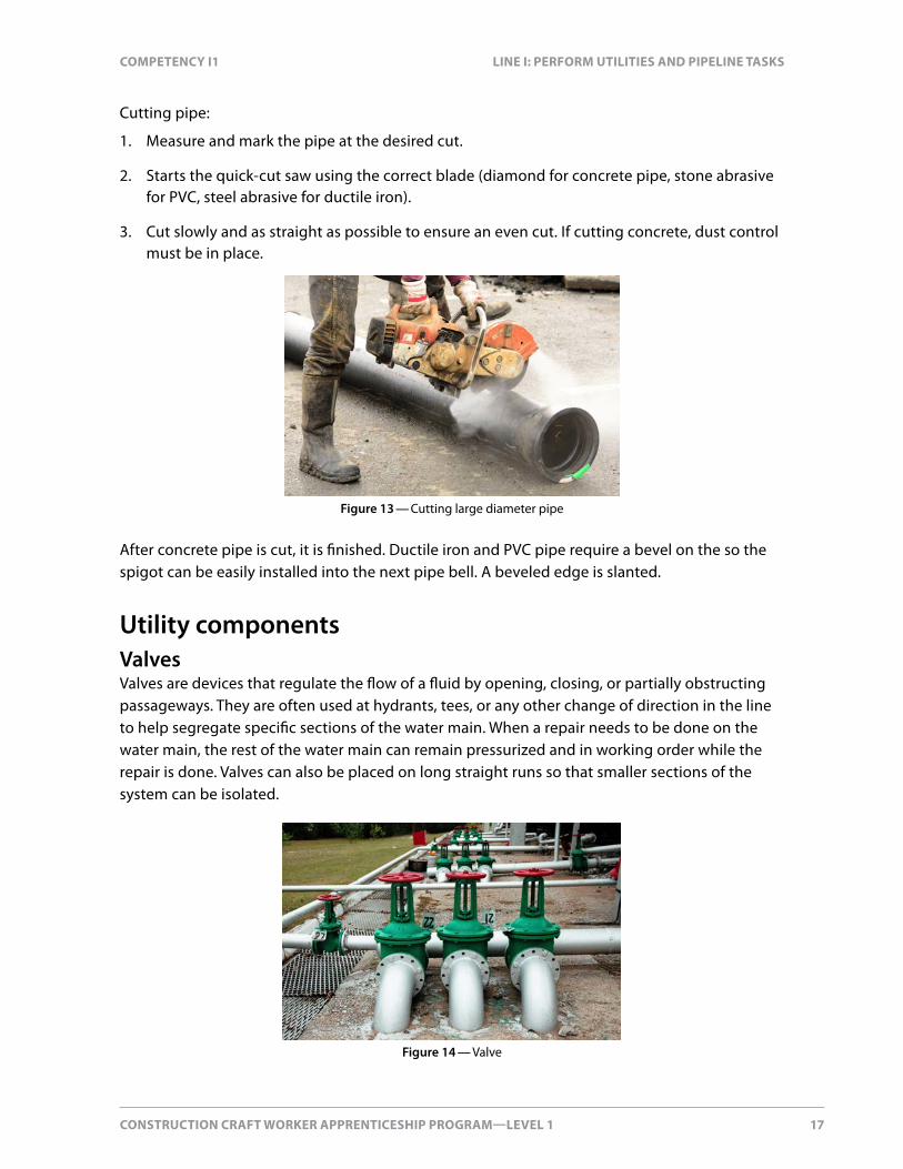
Cutting pipe:
1. Measure and mark the pipe at the desired cut.
2. Starts the quick-cut saw using the correct blade (diamond for concrete pipe, stone abrasive for PVC, steel abrasive for ductile iron).
3. Cut slowly and as straight as possible to ensure an even cut. If cutting concrete, dust control must be in place.
Figure 13 — Cutting large diameter pipe
After concrete pipe is cut, it is finished. Ductile iron and PVC pipe require a bevel on the so the spigot can be easily installed into the next pipe bell. A beveled edge is slanted.
Utility componentsValvesValves are devices that regulate the flow of a fluid by opening, closing, or partially obstructing passageways. They are often used at hydrants, tees, or any other change of direction in the line to help segregate specific sections of the water main. When a repair needs to be done on the water main, the rest of the water main can remain pressurized and in working order while the repair is done. Valves can also be placed on long straight runs so that smaller sections of the system can be isolated.
Figure 14 — Valve

18 CONSTRUCTION CRAFT WORKER APPRENTICESHIP PROGRAM—LEVEL 1
LINE I: PERFORM UTILITIES ANd PIPELINE TASKS COMPETENCy I1
Construction jobs use hydrants to temporarily supply water. The contractor pays the city to use the water. The city supplies a backflow preventer device while the hydrant is being used for construction. The contractor is responsible for returning it to the city.
Figure 15 — Fire hydrant
FittingsTees and bends are used whenever a change of direction is needed on a water main. Bends usually come in the 11.25°, 22.5°, 45°, and 90° bends. They are used because the pipe joints should not deflect. Tees are used where the water main needs to stay in straight alignment, but another main or a large water service needs to tie into the existing main at a perpendicular angle. Valves are often placed at tees to isolate water mains from each other if needed.
Figure 16 — Tees and bends
Storm and sanitary sewer mains have different utility components used with the utility mains. These utility components are manholes, catch basins, lawn basins and fittings.
Manholes, sometimes called utility holes, are underground utility vaults used to house access points for making connections, inspections, valve adjustments or performing maintenance on

CONSTRUCTION CRAFT WORKER APPRENTICESHIP PROGRAM—LEVEL 1 19
COMPETENCy I1 LINE I: PERFORM UTILITIES ANd PIPELINE TASKS
an underground and buried public utility. They are often placed where mains change direction and along stretches of straight runs.
Since the waste materials’ only source of movement comes from gravity, any change of direction can cause a blockage unless precautions are taken to smooth the transition from one direction to another. By placing all direction changes in manholes, maintenance such as removal of blockages can be performed fairly easily.
A catch basin is part of a storm sewer system designed to catch surface water along gutter lines or landscaping areas. Most are designed with a sump in the bottom so that silt and dirt sinks to the bottom and clean water flows out of the outlet and into the storm mains. Often, a trapping hood is placed over the outlet to keep leaves, wood and other debris from floating into the main as well.
When setting a catch basin, the rim elevation is given on the drawing. The rim is the top of the grate where the water flows into the catch basin. From that elevation, the construction craft worker works downward to calculate the elevation of the bottom of the catch basin. For example, if the rim elevation at an elevation of 101.25 m, and the total height of the catch basin components is 1.25 m, the bottom of the catch basin should be set at an elevation of 100.00 m.
Street level
Hood
Floatables
Debris
Catch basin grate
Connection
to sewer
Figure 17 — Catch basin

20 CONSTRUCTION CRAFT WORKER APPRENTICESHIP PROGRAM—LEVEL 1
LINE I: PERFORM UTILITIES ANd PIPELINE TASKS COMPETENCy I1
Lawn basins act like catch basins. Water flows through a grate and then down into a sump. The water eventually rises and flows out of an outlet pipe which runs into the storm sewer main line. Lawn basins tend to be smaller than catch basins and are placed in landscaping and grassy areas. Lawn basins are simply used to carry service water back into the storm system. They should be installed at a natural low point to catch the greatest volume of water possible.
Fittings for underground sewer systems are used to change the direction of piping systems, divert or consolidate the flow, and to change the size of a pipeline. There are many types of standard fittings available for both ductile iron and PVC. Special fittings can be designed and manufactured to meet unique installation needs. Construction craft workers should be able to identify different types of fittings. Tees and wyes are used to connect service lines to the main line. Bends are elbows used to change direction of a line. Plugs and caps are used to seal off ends of a pipe system.
Manhole constructionManholes consist of five main parts. The first piece that is installed is the manhole base. They are the lowest part of the chamber which is usually where all pipes connect to. Manhole bases come in pre-cast forms with connection points already installed. Before placing any manhole base, the sub-base must be compacted to hold the weight of the manhole. It should never shift.
Figure 18 — Manhole
Manhole barrels or risers are the next section to be installed. They range in size from 1 ft. to 4 ft. in height and are used to help bring the manhole close to the finished elevation. Each manhole barrel has ladder rungs already fastened into the barrel. The distance between ladder rungs is always one foot, making it easy to calculate the height. Before laying each barrel, mastic is placed on the top of the previous barrel to bond the barrels together. After the barrel is completely built up, each gap between barrels is grouted on the inside.

CONSTRUCTION CRAFT WORKER APPRENTICESHIP PROGRAM—LEVEL 1 21
COMPETENCy I1 LINE I: PERFORM UTILITIES ANd PIPELINE TASKS
The next section of the concrete manhole is called the concrete top slab or the donut. This is a transition slab that covers the entire surface of the top of the manhole, but has a large hole for workers to enter and exit.
Figure 19 — Installing a manhole
Grade rings (grade adjusters or manhole collars) are placed directly on the manhole donut to bring the manhole to finished grade. They have a large opening in the middle of them for access and are available in thicknesses ranging from 2" to 6". Grade rings are the same thickness all the way around but usually the casting needs to meet the slope of the road. To achieve this, grade rings are used to raise the grade close to the desired amount and then concrete shims are cut to help set the casting at the desired slope.
Figure 20 — Grade rings
The manhole casting or frame is the final component. It sits on top of the manhole structure and holds the manhole cover. The manhole cover is a solid piece of steel used to cover the manhole. Its purpose is to prevent water infiltrating the manhole from the top.

22 CONSTRUCTION CRAFT WORKER APPRENTICESHIP PROGRAM—LEVEL 1
LINE I: PERFORM UTILITIES ANd PIPELINE TASKS COMPETENCy I1
Sometimes manholes are made by pouring in place, called an overpour. All of the necessary pipes are placed on sandbags and a manhole barrel is placed on top so that the tops of the pipes are part way into the next barrel. Then fresh concrete is placed to form the base. After the fresh concrete has been placed to make up the bottom of the manhole, workers shovel and trowel the concrete to form the proper channeling and benching for the base.
Leveling and altering utility componentsHoles may need to be cut into catch basins because the pre-cast holes are in the wrong place or additional holes are needed. Holes are made by cutting a circle of the appropriate size with a quick-cut saw or concrete saw with a diamond blade, and then knocking the concrete out with bolt cutters and a sledgehammer. This also works for knocking holes into concrete pipes.
When a new hole is made, there are no rubber seals in place like in pre-cast manholes. To achieve a good seal, concrete is poured on the outside to seal the new hole. The inside of the manhole or catch basin is grouted to ensure a good seal.
Whether setting a hydrant, a valve, a manhole, or a catch basin, they must be set plumb and level. Even though the manhole casting on top will not be level, the entire manhole from the bottom up must be level. The best way to ensure that a utility component remains level is to prepare a level base. This is done using a builder’s level and survey rod, or a hand level.
Figure 21 — Levelling a utility

CONSTRUCTION CRAFT WORKER APPRENTICESHIP PROGRAM—LEVEL 1 23
COMPETENCy I1 LINE I: PERFORM UTILITIES ANd PIPELINE TASKS
When setting a hydrant, it is important that it is plumb. This again is achieved by placing a hand level on the hydrant riser underneath of the hydrant itself. If this component is plumb than all of the hydrant should also be plumb.
When setting pipes and manhole basins, the components the components must be rigged properly. All rigging equipment must be certified and used correctly. Chains are most commonly used in the utility sector because of their durability but web slings, and wire rope slings are also sometimes used. Many manholes and catch basins require lifting clevise hooks which attach to the manhole making it easier to lift. Catch basins and hydrants are often lifted by belly wrapping a chain around them so they are secure.
Figure 22 — Stacked manhole sections

24 CONSTRUCTION CRAFT WORKER APPRENTICESHIP PROGRAM—LEVEL 1