brick masonry design
TRANSCRIPT

7/28/2019 Brick Masonry Design
http://slidepdf.com/reader/full/brick-masonry-design 1/34
Brick Masonry Design1.2

7/28/2019 Brick Masonry Design
http://slidepdf.com/reader/full/brick-masonry-design 2/34
The following design information is based on Australian Standard AS3700: 2001 Masonry Structures. Reference
to ‘Clauses’ and ‘Formulae’ are those used in AS3700. This information is provided as a guide only to the processes
involved in designing masonry. All masonry should be designed by a suitably qualified structural engineer.
Robustness
AS3700, Clause 4.6.1 requires walls to have an adequate degree of ‘Robustness’. Robustness is a minimum
design requirement, and may be overridden by fire, wind, snow, earthquake or live and dead load requirements.
In robustness calculations (AS3700 Clause 4.6.2), there are height, length, and panel action formulae. By reworking
the standard formulae and inserting known data, it is possible to determine whether a chosen design and Boral brick
will provide adequate robustness, as in the tables below and the charts on pages 1.202 to 1.204.
Bricks & Pavers Technical Manual
Section 1.2. Brick Masonry Design 1.201
ADV03749
Maximum Wall Length (m)
Wall Thickness (mm) Lateral Support One End Lateral Support Both Ends
90 1.08 3.24
110 1.32 3.96
150 1.80 5.40
230 2.76 8.28
Table 3. Maximum Wall Length where One or Both Ends are Laterally Restrained
Table 2. Maximum Height of Walls with Free Ends
Maximum Wall Height (m)
Wall Thickness (mm) No Lateral Support at Top Lateral Support at Top Concrete Slab on Top
90 0.54 2.43 3.24
110 0.66 2.97 3.96
150 0.90 4.05 5.40
230 1.38 6.21 8.28
Pier Thickness (mm) Maximum Height (m)
230 x 230 3.105
350 x 350 4.725
Table 1. Maximum Height of Isolated Piers
In the situation depicted in Table 3 above, height is not limited although length is. This typically applies to lift
shafts and stairwells. Control joints and openings greater than one fifth of the wall height are treated as free
ends unless specific measures are taken to provide adequate lateral support.
Where wall lengths exceed those in Table 3 above, AS 3700 Equation 4.6.2 (4) must be used to determine the maximum
height for a wall of the required length. Should the initial choice of product not provide a suitable solution, then a thicker
Boral brick or increased masonry width or extra restraints should be evaluated.t

7/28/2019 Brick Masonry Design
http://slidepdf.com/reader/full/brick-masonry-design 3/34
Robustness (continued)
How to Use the Boral Robustness Graphs
These charts determine the minimum brick thickness for a known wall height, length and restraint criteria.
Bricks & Pavers Technical Manual
Section 1.2. Brick Masonry Design 1.202
ADV03750
1. Select the graph for the chosen wall restraint
(support) criteria. In this example there is
support on one side and the top is supported by
other than a concrete slab. Typically this would
be a wall supporting roof frames, joined into
another wall at one end and with a door at the
other end.
2. Plot the intersection of the design Wall Height
and the Wall Length on the graph. (For this
example 3 m height x 5 m length).
3. The lines ABOVE the intersection point indicate
wall thickness that are acceptable. In this
example, the intersection point is just below the
line for 110 mm bricks. Therefore a single leaf of
110 mm bricks would be suitable and the most
economical.
8
7
6
5
4
3
2
1
01 22 3 4 5 6 7 8
W
A L L
H E I G
H T
( m
)
W A L L L E N G T H ( m )
230mm
90x90mm
110mm
90mm
150mm
110x110mm
FR
S
R
Laterally supported one end
and top laterally supported
by other than concrete slab
7/28/2019 Brick Masonry Design
http://slidepdf.com/reader/full/brick-masonry-design 4/34
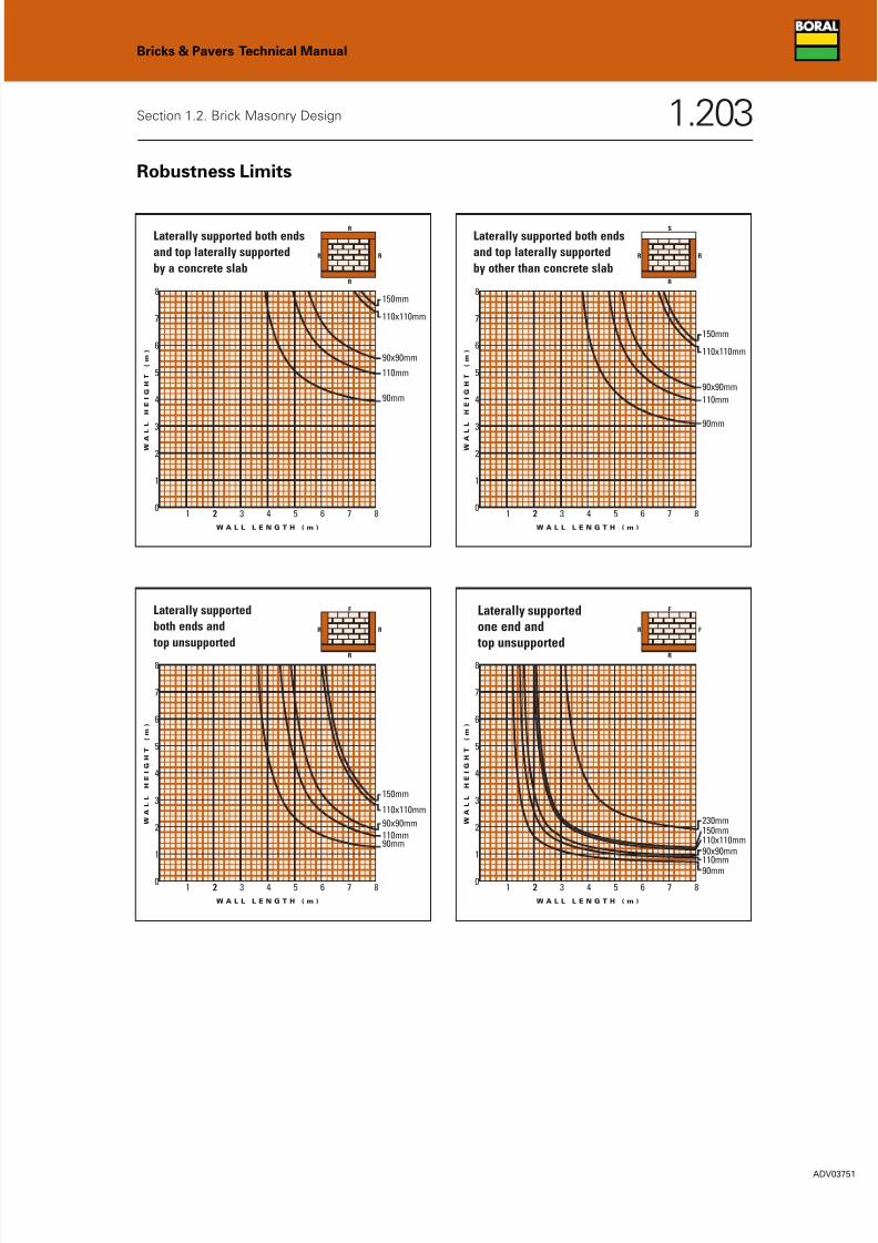
Robustness Limits
Bricks & Pavers Technical Manual
Section 1.2. Brick Masonry Design 1.203
ADV03751
8
7
6
5
4
3
2
1
01 22 3 4 5 6 7 8
W
A
L L
H E I G
H T
( m
)
W A L L L E N G T H ( m )
90x90mm
110mm
90mm
150mm
110x110mm
RR
R
R
Laterally supported both ends
and top laterally supported
by a concrete slab
8
7
6
5
4
3
2
1
01 22 3 4 5 6 7 8
W
A
L L
H E I G
H T
( m
)
W A L L L E N G T H ( m )
90x90mm
110mm
90mm
150mm
110x110mm
RR
S
R
Laterally supported both ends
and top laterally supported
by other than concrete slab
8
7
6
5
4
3
2
1
01 22 3 4 5 6 7 8
W
A
L L
H E I G
H T
( m
)
W A L L L E N G T H ( m )
90x90mm
110mm90mm
150mm
110x110mm
RR
F
R
Laterally supported
both ends and
top unsupported
8
7
6
5
4
3
2
1
01 22 3 4 5 6 7 8
W
A
L L
H E I G
H T
( m
)
W A L L L E N G T H ( m )
230mm
90x90mm110mm
90mm
150mm110x110mm
FR
F
R
Laterally supportedone end and top unsupported

7/28/2019 Brick Masonry Design
http://slidepdf.com/reader/full/brick-masonry-design 5/34
ADV03752
1.204
Bricks & Pavers Technical Manual
Section 1.2. Brick Masonry Design
Robustness Limits
8
7
6
5
4
3
2
1
01 22 3 4 5 6 7 8
W
A
L L
H E I G
H T
( m
)
W A L L L E N G T H ( m )
90x90mm110mm
90mm
150mm
110x110mm
FR
R
R
Laterally supported one end
and top laterally supported
by a concrete slab
8
7
6
5
4
3
2
1
01 22 3 4 5 6 7 8
W
A
L L
H E I G
H T
( m
)
W A L L L E N G T H ( m )
230mm
90x90mm
110mm
90mm
150mm
110x110mm
FR
S
R
Laterally supported one endand top laterally supported
by other than a concrete slab

7/28/2019 Brick Masonry Design
http://slidepdf.com/reader/full/brick-masonry-design 6/34
Masonry Strength
Masonry Strength is defined as resistance to load per unit area. It must be remembered that thicker masonry will
support more load than thinner masonry of the same strength.
Characteristic Compressive Strength of Masonry – f’m
f’m = km kh √f‘uc
km is a mortar strength factor and kh is a factor for the amount of mortar joints.
km is 1.4 for M3 mortar and 1.5 for the stronger M4 mortar (see AS 3700 Table 3.1 for a full list of factors).
kh is 1 for 76 mm high units with 10 mm mortar beds and is 1.24 for 162 mm high bricks with 10 mm mortar
beds (see AS 3700 Table 3.2 to derive factors for other unit and joint heights). In other words, a wall of
double height bricks is more than 20% stronger than a wall of 76 mm high bricks of the same f‘uc.
f’uc is the characteristic unconfined compressive strength of bricks.
Characteristic Flexural Tensile Strength of Masonry – f’mt
In flexing, the top of the arc is in tension and the bottom of the arc is in compression. Masonry is good in
compression but poor in tension. Flexural strength depends on the mortar/brick bond and for design purposes is
generally taken to be zero. Using up to 0.2 MPa is permitted when designing for transient loads such as wind,
earthquake, etc. Higher bending forces may be used for design but these require site testing to verify
construction meets the stated values.
Characteristic Shear Strength of Masonry – f‘ms
Shear strength, like flexural strength, is related to the mortar/brick bond. For design purposes, at the damp
course, it is taken to be zero unless testing shows another value. Elsewhere, mortar joints have f’ ms values of
between 0.15 and 0.35 MPa. ■
Bricks & Pavers Technical Manual
Section 1.2. Brick Masonry Design 1.205
ADV03753

7/28/2019 Brick Masonry Design
http://slidepdf.com/reader/full/brick-masonry-design 7/34
Durability of Masonry
AS3700 requires masonry to be designed to continue functioning satisfactorily throughout its design life without
undue maintenance. That is, all masonry materials, including bricks, mortar and all built-in components, must be
sufficiently durable for the exposure classification of the site (see AS3700 Appendix E). Masonry designed to
meet the requirements of AS3700 Section 5, is deemed to comply with the durability requirements and Table 5.1
defines the durability requirements for bricks, built-in components and mortar in different environments.
Salt attack is the most common durability problem. In the form of a solution, salt can be absorbed into masonry.
As the water evaporates, the salt is drawn towards the outside face. The evaporating water leaves the solution
super-saturated so salt crystals begin to form. The salt crystals grow in the pores just below the surface and
depending on the texture of the brick, the amount of salt, the rate of drying and the temperature, the salt may
fill the pores, exerting very high pressures on the matrix. The energy in the constrained salt crystal increases and
if sufficient ‘pops’ a piece of the outer surface off and salt attack has begun.
Boral bricks graded ‘General Purpose’ (GP) are suitable for use in all walls, excluding external walls in severe
marine environments or in all walls in contact with aggressive soils and environments.
Boral bricks graded ‘Exposure Grade’ (EXP) are suitable for use in all walls including external walls exposed to
severe marine environments, i.e. up to 1 km from a surf coast or up to 100 m from a non surf coast or walls in
contact with aggressive soils and environments. The distances are specified from mean high water mark.
Walls below damp proof course often require greater durability, even if they are well away from the coast, as
they may be subjected to saline, acidic or alkaline soils. If unsure of the corrosive nature of the site, an
inexpensive total soluble salt content test for soil is available in most areas. Remember it is the designer’s
responsibility to specify the appropriate durability grade of bricks, mortar and built-in components and it is the
builder’s responsibility to order bricks, etc. of appropriate durability grade specified by the designer. Brick
manufacturers cannot take any responsibility in this decision as they are not aware of the design requirements
of each site. t
Bricks & Pavers Technical Manual
Section 1.2. Brick Masonry Design 1.206
ADV03754

7/28/2019 Brick Masonry Design
http://slidepdf.com/reader/full/brick-masonry-design 8/34
Durability of Masonry (continued)
Refer to Section 1.4 Property Tables for tabulated properties of individual brick types for their salt attack
resistance category.
Mortar mix requirements for durability are referred in Table 11, page 1.301 of this manual and are detailed in
AS3700 Table 10.1.
M4 mortars are required and mortar joints must be tooled in all situations requiring exposure grade materials.
Concrete floors, paths and steps are a source of sulfate salts that if dissolved in water may enter the brickwork and
cause salt attack. Exposed slabs supported on external brickwork should clear the brickwork by 50 mm and
incorporate a drip groove to prevent the run-off from the slab running down the brickwork. A damp proof course
(usually a double layer) is also used under the slab on top of the bricks to prevent water passing through the slab
into the bricks and as a slip joint to prevent a build up of forces as the concrete shrinks and the bricks expand
over time.
Landscaping and gardening practices are also possible sources of salt attack. Care must be taken to not bridge
the damp proof course when landscaping at the base of walls. Watering gardens and lawns, against walls, may
cause salts (fertilisers) to splash up on to the wall where they are absorbed and may cause salt attack. ■
Bricks & Pavers Technical Manual
Section 1.2. Brick Masonry Design 1.207
ADV03755

7/28/2019 Brick Masonry Design
http://slidepdf.com/reader/full/brick-masonry-design 9/34
Brick Ties
In brick veneer construction, ties are used to pass all the lateral out-of-plane loads and forces (such as from wind)
to the structural backing. In cavity brick construction ties either pass the lateral out-of-plane loads and forces to
the stronger leaf or share them between the leaves.
The design of ties in masonry for structural purposes must comply with AS3700 Clause 7.7 for veneer or Clause
7.8 for cavity construction. For small buildings the tie requirements are covered in AS3700 Clause 12.3.4 for brick
veneer construction and Clause 12.3.3.2 for cavity brick construction.
Type A ties are those that have no specific seismic design characteristics. It is difficult to find brick ties other
than Type A in Australia. Ties are available in heavy, medium and light duty in galvanised steel, stainless steel
and plastic. Plastic ties are usually reserved for acoustic applications. Stainless steel ties are used in situations
requiring exposure grade materials or very long life. Galvanised steel ties are those most commonly used.
The Newcastle (NSW) earthquake which occurred in 1989 showed masonry survived well except where the ties
were deficient. Problems found included:
• galvanised ties rusted through;
• ties only built into one leaf during construction;
• loose ties;
• absent ties; and,
• incorrect duty ties used.
Ties are required to meet the durability requirement of the site for the design life of the building. Should the
design life of the building be exceeded and the ties begin to fail, they can be replaced with remedial ties but this
is a very expensive process and as ties are hidden it is unlikely they will be seen until a catastrophic failure
occurs. As sustainability considerations become more important, the life of buildings is likely to be extended.
Properly maintained, brick buildings may last for centuries. It should be remembered that stainless steel brick
ties offer a longer service life and, although more expensive as a proportion of the overall building cost, the
difference is trivial. ■
Bricks & Pavers Technical Manual
Section 1.2. Brick Masonry Design 1.208
ADV03756
7/28/2019 Brick Masonry Design
http://slidepdf.com/reader/full/brick-masonry-design 10/34
Movement in Masonry Walls
To allow for movements in masonry (expansion and contraction and footing movement) control joints are
required. These can usually be constructed so that the expansion joint and the articulation joint are one and
the same.
Expansion Joints
Expansion and contraction must be allowed for in masonry design by inserting control joints at spacings designed
to suit the magnitude of the movement.
Clay products expand permanently over time. This is the opposite of cement-based products, which permanently
shrink. For this reason it is unwise to use clay and concrete units in the same band in a wall. If clay bricks are
used in concrete framed buildings, control joint spacing and workmanship are critical, as the bricks will expand
as the concrete frame shrinks.
The magnitude of thermal changes varies from brick to brick depending on the many factors, however, allowing
0.008 mm/m/°C is usually recommended. Expansion and contraction from wetting and drying of clay bricks is less
than for concrete and calcium silicate products and usually can be ignored in brick masonry design.
AS3700, Clause 4.8 requires expansion joints to be spaced to limit panel movement so that movement from both
sides closes joints by less than 15 mm and joints are at least 5 mm wide when closed. This means the gap, when
constructed, should be 20-25 mm. However, in most buildings articulation joints are used and these are closer
than required for expansion making separate expansion joints unnecessary.
Articulation Joints
Articulation joints are vertical gaps that allow for minor footing movements, to prevent distress or significant
wall cracking. Articulation joints provide the flexibility needed when building on reactive clay soils and usually
are not required for masonry on stable sites (classified according to AS2870). Spacing of articulation joints
depends on the site classification and the slab or footing design, but where used must be placed no closer than
0.5 metres and no further than 3 metres from all corners. The width of articulation joints depends on the height
of the masonry: 10 mm for masonry up to 3 metres and 15 mm for masonry up to 6 metres high. t
Bricks & Pavers Technical Manual
Section 1.2. Brick Masonry Design 1.209
ADV03757

7/28/2019 Brick Masonry Design
http://slidepdf.com/reader/full/brick-masonry-design 11/34
Movement in Masonry Walls (continued)
Control Joints (General)
Control joints should be used beside large openings, where wall thickness changes (except where this is for
support eg. engaged piers), where wall height changes by more than 20%, at changes of level in footings and at
other points of potential cracking. Control joints must not continue through bond beams.
Ideally, control joints are located near a corner and concealed behind a down pipe. The bricklayer and renderer
must keep the control joint clean, otherwise, bridging mortar or render will induce cracks as the masonry moves.
External control joints should be finished with a soft flexible sealant to prevent moisture penetration.
The design and construction of control gaps in the external leaf of a full brick wall is identical to that in brick
veneer. In internal masonry, control gaps are not usually required, except at re-entrant angles in long walls.
However, where an internal control joint is required the design is as for external leaves but the thermal
component may be ignored in calculations. Internal control joints can usually be located at a full-height opening
such as a door or window.
Ties are required on both sides of a control joint, but where it is not possible to use them masonry flexible
anchors (MFAs) must be used across the joint. Where MFAs are used in walls over 3 metres or in walls exposed
to high winds, MFAs must be built in at half height and every seventh course (600 mm) above. MFAs are ties that
are of a type that only allows movement in one plane. Unless ties are used, control joints create a ‘free end’ in
terms of Robustness and Fire Resistance Level calculations for structural adequacy, so their positioning is critical
to the overall design of the structure.
In portal frame construction, the control
joint is positioned at a column so that
both ends can be tied to the column’s
flanges.
The principles of control joint
construction are illustrated in the
adjacent figure.
Bricks & Pavers Technical Manual
Section 1.2. Brick Masonry Design 1.210
ADV03758
Articulation joints withcompressible backingand mastic sealant
Dividing wall witharticulation joint andMFA's at intersectionwith cavity wall
Brick ties on each sideof articulation joint
Articulationjoint

7/28/2019 Brick Masonry Design
http://slidepdf.com/reader/full/brick-masonry-design 12/34
Thermal Properties
As at 2004, the Building Code of Australia (BCA) requires energy efficiency performance for housing (BCA Vol 2).
Australia is divided into 8 climatic zones. (Sydney and Perth are in Zone 5, Adelaide and Melbourne are in Zone
6, Brisbane is in Zone 2 and Canberra is in Zone 7). The zones and Local Government boundaries are detailed on
a map, which is available from the Australian Building Codes Board (www.abcb.gov.au) but the Local Council
should be able to provide the information where there is any doubt.
The BCA set the minimum energy efficiency requirement of 3.5 stars for Zones 1-3 and 4 stars for Zones 4-8. While
the BCA sets these minimum requirements, State governments may adopt these minimums or may opt for different
requirements. Local authorities may adopt higher star ratings but may not opt for lower ratings than the State adopts.
The ABCB has indicated they are considering requiring 5 stars in line with Victoria and ACT.
Victoria requires a 5 star rating on the building fabric from July 2005 using ‘FirstRate’ or ‘NatHERS’ software.
Pre-July 2004, the requirement was 4 stars on the building fabric. Post July 2004, the requirement is either 5 stars
on the building fabric; or 4 stars on the building fabric plus water saving measures and a solar hot water system;
or 4 stars on the building fabric plus water saving measures and a rain water tank.
ACT requires 5 stars from ‘ACTHERS’ software.
South Australia requires 4 stars from ‘NatHERS’ or ‘FirstRate’ software.
The NSW situation is complex. From 1 July 2004 in the Sydney Metropolitan area and 1 July 2005 eleswhere in the
State all new housing, dual occupancies and small (under 300 m2) hostel type accommodation will be required to
have a BASIX rating. From 1 February 2005 in the Sydney Metropolitan area and 1 October 2005 elsewhere in the
state this will apply to all new residential developments. From 1 July 2005 these measures apply to alterations to
residences in Sydney and from 1 October 2005 elsewhere in the State. BASIX is a comprehensive sustainability
rating software, incorporating energy and water efficiency initially with the intention of including stormwater,
transport, site ecology, waste and recycling and materials at a later date. It is a web-based system in which you
enter data about the development in boxes and the whole has to meet targets to get Development Application
approval. BASIX is aimed at achieving energy reductions of 25% (going up to 40% in July 2006) and potable water
savings of 40%.
Different star rating software can produce different ratings. To overcome this, the Australian Building Codes Board
has developed a protocol to ensure all star rating software, as nearly as practical, produces the same rating for the
same design.t
Bricks & Pavers Technical Manual
Section 1.2. Brick Masonry Design 1.211
ADV03759
7/28/2019 Brick Masonry Design
http://slidepdf.com/reader/full/brick-masonry-design 13/34
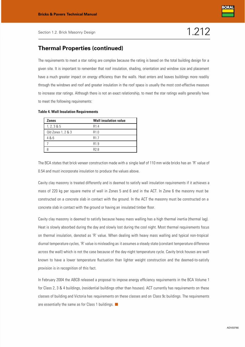
Thermal Properties (continued)
The requirements to meet a star rating are complex because the rating is based on the total building design for a
given site. It is important to remember that roof insulation, shading, orientation and window size and placement
have a much greater impact on energy efficiency than the walls. Heat enters and leaves buildings more readily
through the windows and roof and greater insulation in the roof space is usually the most cost-effective measure
to increase star ratings. Although there is not an exact relationship, to meet the star ratings walls generally have
to meet the following requirements:
Table 4. Wall Insulation Requirements
The BCA states that brick veneer construction made with a single leaf of 110 mm wide bricks has an ‘R’ value of
0.54 and must incorporate insulation to produce the values above.
Cavity clay masonry is treated differently and is deemed to satisfy wall insulation requirements if it achieves a
mass of 220 kg per square metre of wall in Zones 5 and 6 and in the ACT. In Zone 6 the masonry must be
constructed on a concrete slab in contact with the ground. In the ACT the masonry must be constructed on a
concrete slab in contact with the ground or having an insulated timber floor.
Cavity clay masonry is deemed to satisfy because heavy mass walling has a high thermal inertia (thermal lag).
Heat is slowly absorbed during the day and slowly lost during the cool night. Most thermal requirements focus
on thermal insulation, denoted as ‘R’ value. When dealing with heavy mass walling and typical non-tropical
diurnal temperature cycles, ‘R’ value is misleading as it assumes a steady state (constant temperature difference
across the wall) which is not the case because of the day-night temperature cycle. Cavity brick houses are well
known to have a lower temperature fluctuation than lighter weight construction and the deemed-to-satisfy
provision is in recognition of this fact.
In February 2004 the ABCB released a proposal to impose energy efficiency requirements in the BCA Volume 1
for Class 2, 3 & 4 buildings, (residential buildings other than houses). ACT currently has requirements on these
classes of building and Victoria has requirements on these classes and on Class 9c buildings. The requirements
are essentially the same as for Class 1 buildings. ■
Zones Wall insulation value1, 2, 3 & 5 R1.4
Qld Zones 1, 2 & 3 R1.0
4 & 6 R1.7
7 R1.9
8 R2.8
Bricks & Pavers Technical Manual
Section 1.2. Brick Masonry Design 1.212
ADV03760
7/28/2019 Brick Masonry Design
http://slidepdf.com/reader/full/brick-masonry-design 14/34
Masonry Design for Fire Resistance
Fire Resistance Levels (FRL)
FRLs come from the Building Code of Australia’s (BCA) Volume 1 tables for Type A, B or C construction. The Type of
construction depends on the Class of building and the number of stories or floors. FRLs for housing come from BCA
Volume 2.
There are three figures in the Fire Resistance Level.
Eg: FRL 120/60/90 means that the wall must achieve Structural Adequacy for 120 minutes / Integrity for 60 minutes /
Insulation for 90 minutes.
Structural Adequacy
This governs the wall’s height, length, thickness and restraints. Brick suppliers do not control the wall height,
length or restraints so therefore do not control Structural Adequacy.
Integrity
This is the resistance to the passage of flame or gas. To provide ‘integrity’, walls must be structurally adequate
and they must maintain insulation. Extensive fire testing of masonry has shown integrity to be closely related to
structural adequacy or insulation. AS 3700 therefore allows Integrity to be equal to the lesser of the Structural
Adequacy or the Insulation periods.
Insulation
This is resistance to the passage of heat through the wall. Insulation is a function of the thickness of the brick
as shown in Table 5, page 1.222 of this manual. ■
Bricks & Pavers Technical Manual
Section 1.2. Brick Masonry Design 1.213
ADV03761

7/28/2019 Brick Masonry Design
http://slidepdf.com/reader/full/brick-masonry-design 15/34
Masonry Design for Structural Adequacy FRL
Structural Adequacy is a minimum provision and may be overridden by design for robustness, wind, live or
earthquake loads.
A fire on one side of a wall will heat that side, making it expand and lean towards the fire. When the lean or bow
reaches half the thickness of the original wall, the wall becomes structurally inadequate. The formulae in
AS3700, Clause 6.3.2.2 limits the panel size, depending on its restraints and thickness.
The Slenderness ratio (Srf) of a proposed wall is calculated according to AS 3700 Clause 6.3.2.2. If this value is
less than the maximum Srf
in Table 6.1 of the Standard [or the Srf
calculated from Fire Tests and AS 3700 Clause
6.3.3(b)(ii)], then the wall complies. If the S rf of the wall is greater than the maximum permissible, it must be
recalculated for an increased thickness and/or extra restraints.
There are 3 formulae for calculating Srf.
AS 3700 Formula 6.3.2.2 (1) and (2) are the formulae for vertically spanning walls (with no support along either
vertical edge).
Formula (1) and (2) always govern where there is no end restraint, and often govern where walls are long, relative
to their height. Projects with multiple wall lengths (eg: home units) can use this formula as a ‘one size fits all’
method of calculating the wall thickness.
AS 3700 Formula 6.3.2.2 (3) allows a wall to exceed the height given by formula (1) and (2) provided the top and
at least one end is supported.
AS 3700 Formula 6.3.2.2 (4) allows a wall to exceed the height given in formula (3) where walls are short, relative
to their height (eg: a lift well or vent shaft). Short walls with no top restraint often occur in situations like portal
frame factories.
For cavity walls where both leaves are equally loaded (within 10 per cent of each other, including where there is
no load on either leaf) the thickness is equal to two-thirds of the sum of the thicknesses of both leaves and the
edge restraint condition is that for the leaf not exposed to the fire. Where one leaf is more heavily loaded than
the other, the thickness and edge restraint condition is that of the more heavily loaded leaf. Where cavity walls
are constructed with leaves of different masonry unit types, the structural adequacy is based on the less fire
resistant material.t
Bricks & Pavers Technical Manual
Section 1.2. Brick Masonry Design 1.214
ADV03762

7/28/2019 Brick Masonry Design
http://slidepdf.com/reader/full/brick-masonry-design 16/34
Masonry Design for Structural Adequacy FRL (continued)
Refer to the Structural Adequacy Graphs on the following pages for maximum height and length values for walls
of different thicknesses and restraint conditions.
An appropriately qualified engineer should check all calculations. Other loads may supersede Structural
Adequacy requirements.
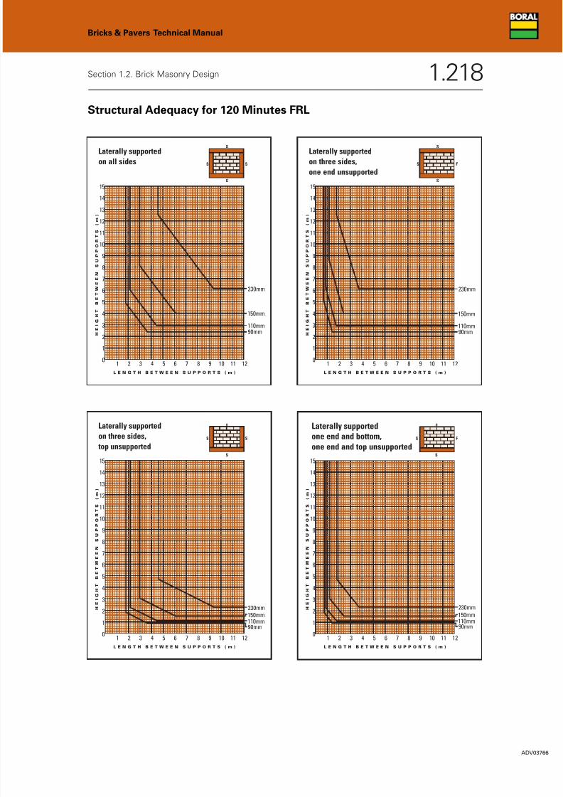
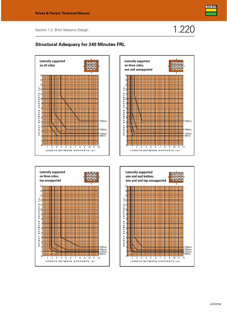
How to Use the Boral Structural Adequacy FRL Graphs
Bricks & Pavers Technical Manual
Section 1.2. Brick Masonry Design 1.215
ADV03763
1. Select the graph with Structural Adequacy for
the required minutes. (240 minutes for this
example).
2. Select the graph for the chosen wall restraint
(support) criteria. (Support on both vertical
edges, top and bottom for this example).
3. Plot the intersection of the design Wall Height
and the Wall Length on the graph. (For this
example 3 m height x 5 m length).
4. The line ABOVE the intersection indicates the
minimum brick thickness required for the wall.
In this example, 150 mm bricks would be
suitable and the most economical.
15
14
13
12
11
10
9
8
7
6
5
4
3
2
1
01 2 3 4 5 6 7 12111098
H E I G
H T
B E T W E
E N
S U
P P O
R T S
( m
)
L E N G T H B E T W E E N S U P P O R T S ( m )
110mm90mm
150mm
230mm
SS
S
S
Laterally supportedon all sides

7/28/2019 Brick Masonry Design
http://slidepdf.com/reader/full/brick-masonry-design 17/34
ADV03764
1.216
Bricks & Pavers Technical Manual
Section 1.2. Brick Masonry Design
Structural Adequacy for 60 Minutes FRL
15
14
13
12
11
10
9
8
7
6
5
4
3
2
1
01 2 3 4 5 6 7 12111098
H E I G
H T
B E T W
E E
N
S U
P P O R T S
( m
)
L E N G T H B E T W E E N S U P P O R T S ( m )
110mm
90mm
150mm
230mm
SS
S
S
Laterally supported
on all sides
15
14
13
12
11
10
9
8
7
6
5
4
3
2
1
01 2 3 4 5 6 7 12111098
H E I G
H T
B E T W
E E
N
S U
P P O R T S
( m
)
L E N G T H B E T W E E N S U P P O R T S ( m )
110mm
90mm
150mm
230mm
FS
S
S
Laterally supported
on three sides,
one end unsupported
15
14
13
12
11
10
9
8
7
6
5
4
3
2
1
01 2 3 4 5 6 7 12111098
H E I G
H T
B E T W E
E N
S U
P P O
R T S
( m
)
L E N G T H B E T W E E N S U P P O R T S ( m )
110mm
90mm
150mm
230mm
SS
F
S
Laterally supported
on three sides,
top unsupported
15
14
13
12
11
10
9
8
7
6
5
4
3
2
1
01 2 3 4 5 6 7 12111098
H E I G
H T
B E T W E
E N
S U
P P O
R T S
( m
)
L E N G T H B E T W E E N S U P P O R T S ( m )
110mm
90mm
150mm
230mm
FS
F
S
Laterally supported
one end and bottom,
one end and top unsupported

7/28/2019 Brick Masonry Design
http://slidepdf.com/reader/full/brick-masonry-design 18/34
ADV03765
1.217
Bricks & Pavers Technical Manual
Section 1.2. Brick Masonry Design
Structural Adequacy for 90 Minutes FRL
15
14
13
12
11
10
9
8
7
6
5
4
3
2
1
01 2 3 4 5 6 7 12111098
H E I G
H T
B E T W
E E
N
S U
P P O R T S
( m
)
L E N G T H B E T W E E N S U P P O R T S ( m )
110mm90mm
150mm
230mm
SS
S
S
Laterally supported
on all sides
15
14
13
12
11
10
9
8
7
6
5
4
3
2
1
01 2 3 4 5 6 7 12111098
H E I G H T
B E T W E
E N
S U P P O
R T S
( m
)
L E N G T H B E T W E E N S U P P O R T S ( m )
110m m90mm
150m m
230mm
FS
S
S
Laterally supported
on three sides,
one end unsupported
15
14
13
12
11
10
9
8
7
6
5
4
3
2
1
01 2 3 4 5 6 7 12111098
H E I G
H T
B E T W E
E N
S U
P P O
R T S
( m
)
L E N G T H B E T W E E N S U P P O R T S ( m )
110mm90mm
150mm
230mm
SS
F
S
Laterally supported
on three sides,
top unsupported
15
14
13
12
11
10
9
8
7
6
5
4
3
2
1
01 2 3 4 5 6 7 12111098
H E I G
H T
B E T W E
E N
S U
P P O
R T S
( m
)
L E N G T H B E T W E E N S U P P O R T S ( m )
110mm90mm
150mm
230mm
FS
F
S
Laterally supportedone end and bottom,
one end and top unsupported
7/28/2019 Brick Masonry Design
http://slidepdf.com/reader/full/brick-masonry-design 19/34
ADV03766
1.218
Bricks & Pavers Technical Manual
Section 1.2. Brick Masonry Design
Structural Adequacy for 120 Minutes FRL
15
14
13
12
11
10
9
8
7
6
5
4
3
2
1
01 2 3 4 5 6 7 12111098
H E I G
H T
B E T W
E E
N
S U
P P O R T S
( m
)
L E N G T H B E T W E E N S U P P O R T S ( m )
110mm90mm
150mm
230mm
SS
S
S
Laterally supported
on all sides
15
14
13
12
11
10
9
8
7
6
5
4
3
2
1
01 2 3 4 5 6 7 12111098
H E I G
H T
B E T W
E E
N
S U
P P O R T S
( m
)
L E N G T H B E T W E E N S U P P O R T S ( m )
110mm90mm
150mm
230mm
FS
S
S
Laterally supported
on three sides,
one end unsupported
15
14
13
12
11
10
9
8
7
6
5
4
3
2
1
01 2 3 4 5 6 7 12111098
H E I G
H T
B E T W E
E N
S U
P P O
R T S
( m
)
L E N G T H B E T W E E N S U P P O R T S ( m )
110mm90mm
150mm230mm
SS
F
S
Laterally supported
on three sides,
top unsupported
15
14
13
12
11
10
9
8
7
6
5
4
3
2
1
01 2 3 4 5 6 7 12111098
H E I G
H T
B E T W E
E N
S U
P P O
R T S
( m
)
L E N G T H B E T W E E N S U P P O R T S ( m )
110mm90mm
150mm
230mm
FS
F
S
Laterally supportedone end and bottom,
one end and top unsupported

7/28/2019 Brick Masonry Design
http://slidepdf.com/reader/full/brick-masonry-design 20/34
ADV03767
1.219
Bricks & Pavers Technical Manual
Section 1.2. Brick Masonry Design
Structural Adequacy for 180 Minutes FRL
15
14
13
12
11
10
9
8
7
6
5
4
3
2
1
01 2 3 4 5 6 7 12111098
H E I G
H T
B E T W
E E
N
S U
P P O R T S
( m
)
L E N G T H B E T W E E N S U P P O R T S ( m )
110mm90mm
150mm
230mm
SS
S
S
Laterally supported
on all sides
15
14
13
12
11
10
9
8
7
6
5
4
3
2
1
01 2 3 4 5 6 7 12111098
H E I G
H T
B E T W
E E
N
S U
P P O R T S
( m
)
L E N G T H B E T W E E N S U P P O R T S ( m )
110mm90mm
150mm
230mm
FS
S
S
Laterally supported
on three sides,
one end unsupported
15
14
13
12
11
10
9
8
7
6
5
4
3
2
1
01 2 3 4 5 6 7 12111098
H E I G
H T
B E T W E
E N
S U
P P O
R T S
( m
)
L E N G T H B E T W E E N S U P P O R T S ( m )
110mm90mm
150mm230mm
SS
F
S
Laterally supported
on three sides,
top unsupported
15
14
13
12
11
10
9
8
7
6
5
4
3
2
1
01 2 3 4 5 6 7 12111098
H E I G
H T
B E T W E
E N
S U
P P O
R T S
( m
)
L E N G T H B E T W E E N S U P P O R T S ( m )
110mm90mm
150mm230mm
FS
F
S
Laterally supportedone end and bottom,
one end and top unsupported
7/28/2019 Brick Masonry Design
http://slidepdf.com/reader/full/brick-masonry-design 21/34
ADV03768
1.220
Bricks & Pavers Technical Manual
Section 1.2. Brick Masonry Design
Structural Adequacy for 240 Minutes FRL
15
14
13
12
11
10
9
8
7
6
5
4
3
2
1
01 2 3 4 5 6 7 12111098
H E I G
H T
B E T W
E E
N
S U
P P O R T S
( m
)
L E N G T H B E T W E E N S U P P O R T S ( m )
110mm90mm
150mm
230mm
SS
S
S
Laterally supported
on all sides
15
14
13
12
11
10
9
8
7
6
5
4
3
2
1
01 2 3 4 5 6 7 12111098
H E I G
H T
B E T W
E E
N
S U
P P O R T S
( m
)
L E N G T H B E T W E E N S U P P O R T S ( m )
110mm90mm
150mm
230mm
FS
S
S
Laterally supported
on three sides,
one end unsupported
15
14
13
12
11
10
9
8
7
6
5
4
3
2
1
01 2 3 4 5 6 7 12111098
H E I G
H T
B E T W E
E N
S U
P P O
R T S
( m
)
L E N G T H B E T W E E N S U P P O R T S ( m )
110mm90mm
150mm230mm
SS
F
S
Laterally supported
on three sides,
top unsupported
15
14
13
12
11
10
9
8
7
6
5
4
3
2
1
01 2 3 4 5 6 7 12111098
H E I G
H T
B E T W E
E N
S U
P P O
R T S
( m
)
L E N G T H B E T W E E N S U P P O R T S ( m )
110mm90mm
150mm230mm
FS
F
S
Laterally supportedone end and bottom,
one end and top unsupported

7/28/2019 Brick Masonry Design
http://slidepdf.com/reader/full/brick-masonry-design 22/34
Structural Adequacy for Panels with Unsupported Ends
This figure shows the situation where there is support top and bottom but none on the sides. This applies
where there are control joints, large openings, long walls, etc. To use this graph select the desired FRL in
minutes and the height of the wall. The line above the intersection shows the brick thickness required.
Maximum Wall Heights for Structural Adequacy for any Wall Length
Bricks & Pavers Technical Manual
Section 1.2. Brick Masonry Design 1.221
ADV03769
7
6
5
4
3
2
1
060 90 120 240180
M
A
X I M
U M
W
A L L
H E I G H T
( m
)
F R L F O R S T R U C T U R A L A D E Q U A C Y
( m i n u t e s )
110mm
90mm
150mm
230mm
FF
S
S
Top and bottom supported,
ends not supported.
7/28/2019 Brick Masonry Design
http://slidepdf.com/reader/full/brick-masonry-design 23/34
Masonry Design for Integrity FRL
It is impractical to provide test results for all possible wall designs, and therefore ‘Integrity’ must be proved in
some other way. The most practical way to prove ‘Integrity’ is to prove ‘Structural Adequacy’ and ‘Insulation’
equal to or better than the ‘Integrity’ requirement. Logically, if the wall is designed to minimise ‘bowing’ it will
not crack and therefore resist the passage of flame and gas for the specified time.
This method is also the best way to prove ‘Integrity’ even when a wall may not be required to comply with a
‘Structural Adequacy’ FRL value, such as is the case with non-load bearing walls. Eg. If the BCA requires an FRL
of -/90/90, the wall has no actual ‘Structural Adequacy’ requirement, but to prove Integrity of 90 minutes, the
wall must be structurally adequate for at least 90 minutes. ■
Masonry Design for Insulation FRL
Insulation is the one FRL component that a brick manufacturer does control. It is governed by the ‘type of
material’ and ‘material thickness’.
‘Material thickness’ (t) is defined in AS3700, Clause 6.5.2 as the overall thickness for bricks with cores not more
than 30% of the brick’s overall volume.
For cavity walls, t = the sum of material thicknesses in both leaves.
Effect of Recesses for Services on FRLs
Recesses that are less than half of the masonry thickness and are less than 10,000 mm2 (0.01 m2) for both sides
within any 5 m2 of the wall area do not have an effect on fire ratings.
If these limits are exceeded, the masonry design thickness must be reduced by the depth of the recess. ■
Bricks & Pavers Technical Manual
Section 1.2. Brick Masonry Design 1.222
ADV03770
Wall thickness (mm) 90 110 140 or 150160 (150 plus 10 mm
230180 220
render on both sides) (90/90 cavity) (110/110 cavity)
Insulation period (minutes) 60 90 120 180 240 240 240
Table 5. Insulation periods for standard bricks (minutes)
Note: Wall thickness excludes render on side of wall exposed to fire. ■
7/28/2019 Brick Masonry Design
http://slidepdf.com/reader/full/brick-masonry-design 24/34
Effect of Chases on Fire Rated Masonry
Structural Adequacy FRL
To assess the effect of chases on Structural Adequacy FRLs, the direction in which the wall spans must be taken
into account.
• Walls spanning vertically may be chased vertically to full height but horizontal chases are limited in length
to 4 times the wall’s thickness.
• Walls spanning vertically and horizontally may be chased either horizontally up to half the wall’s length or
vertically up to half the wall’s height.
If these limits are exceeded, the masonry design thickness must be reduced by the depth of the chase or, in the
case of vertical chases, designed as 2 walls with unsupported ends at the chase. Horizontal chases in all walls
should be kept to a bare minimum.
Note: Chases affect the sound reduction capacity of walls. See ‘Acoustic Design’ page 1.225 of this manual.
Integrity and Insulation FRLs
AS3700 limits the maximum depth of chase to 30 mm and the maximum area of chase to 1,000 mm2. The
maximum total area of chases on both sides of any 5 m2 of wall is limited to 100,000 mm2 (0.1 m2). If these limits
are exceeded, the masonry design thickness must be reduced by the depth of the chase. ■
Bricks & Pavers Technical Manual
Section 1.2. Brick Masonry Design 1.223
ADV03771

7/28/2019 Brick Masonry Design
http://slidepdf.com/reader/full/brick-masonry-design 25/34
Options for Increasing FRLs
Structural Adequacy FRLs can be increased by adding wall stiffeners, by increasing the overall thickness, by
adding reinforcement or by protecting the wall, e.g. with Boral Plasterboard’s ‘FireStop’ board, fixed to furring
channels (on both sides of the wall if a fire rating is required from both sides). Note: Be careful of the effect of
plasterboard on sound reduction in party walls. See ‘Acoustic Design’ page 1.225 of this manual.
Integrity FRLs are increased by increasing the other two FRL values to the required Integrity FRL.
Insulation FRLs can be increased by adding another leaf of masonry, by rendering both sides of the wall if the fire
can come from either side. Note: Only ONE thickness of render is added to the material thickness and that must
be on the ‘cold’ side because the render on the exposed face will drop off early in a fire. ■
Bricks & Pavers Technical Manual
Section 1.2. Brick Masonry Design 1.224
ADV03772
7/28/2019 Brick Masonry Design
http://slidepdf.com/reader/full/brick-masonry-design 26/34
ACOUSTIC DESIGN
Acoustic Performance Rating
The BCA requirements for Class 1, 2, 3 and 9c buildings changed in May 2004 with the issue of Amendment 14.
Amendment 14 has been adopted by all jurisdictions other than Queensland, Northern Territory and Western
Australia where Amendment 13 continues in force. It must be remembered that the BCA requirements are the
minimum requirements and some Local Authorities may require better performance. Check with Local Councils
for specific requirements above the BCA minimums. Note: Incremental improvements in sound insulation come
at an ever-increasing cost.
The BCA Amendment 14 requirements are met by:
1. Testing a sample of constructed walls to verify that they meet the Weighted Standardised Level Difference
(Dnt,w – explained further in ‘Acoustic Performance On-Site’ on page 1.231 of this manual) requirements; or
2. Constructing walls using the same materials and techniques as walls that have been constructed and tested in a
laboratory and shown to meet the Weighted Sound Reduction Index (Rw) requirements; or,
3. Constructing walls using the materials and techniques in the ‘Acceptable Construction Practice’ section of
the BCA; and,
4. Where impact sound reduction is required, it is to be achieved by discontinuous construction; and,
5. Except where the requirements are verified by on-site testing, chasing of services into masonry walls is not
allowed and electrical outlets on either side of the wall must be offset by no less than 100 mm. t
Bricks & Pavers Technical Manual
Section 1.2. Brick Masonry Design 1.225
ADV03773
7/28/2019 Brick Masonry Design
http://slidepdf.com/reader/full/brick-masonry-design 27/34
ADV03774
1.226
Bricks & Pavers Technical Manual
Section 1.2. Brick Masonry Design
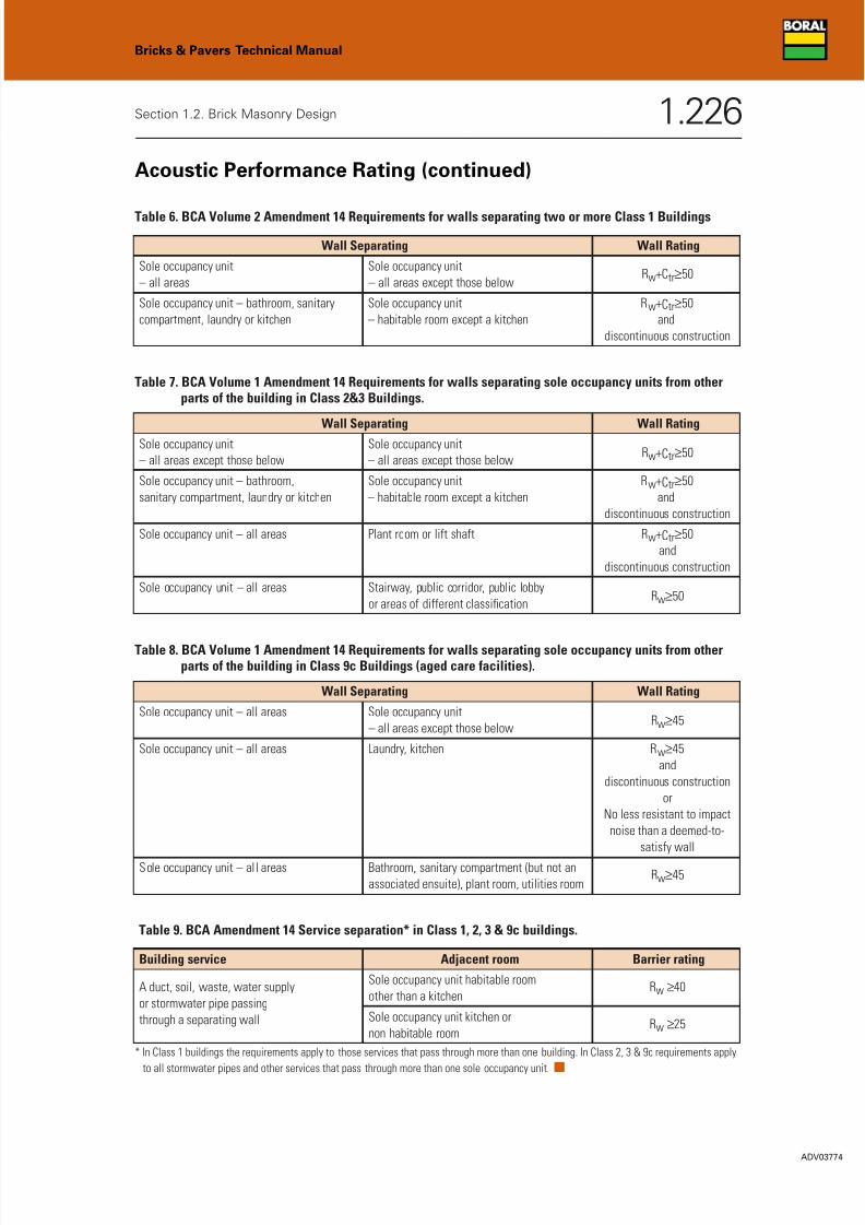
Building service Adjacent room Barrier rating
A duct, soil, waste, water supplySole occupancy unit habitable room
Rw ≥40
or stormwater pipe passingother than a kitchen
through a separating wall Sole occupancy unit kitchen orRw ≥25
non habitable room
Table 9. BCA Amendment 14 Service separation* in Class 1, 2, 3 & 9c buildings.
* In Class 1 buildings the requirements apply to those services that pass through more than one building. In Class 2, 3 & 9c requirements apply
to all stormwater pipes and other services that pass through more than one sole occupancy unit.■
Wall Separating Wall Rating
Sole occupancy unit – all areas Sole occupancy unitRw≥45
– all areas except those below
Sole occupancy unit – all areas Laundry, kitchen Rw≥45
and
discontinuous construction
or
No less resistant to impact
noise than a deemed-to-
satisfy wall
Sole occupancy unit – al l areas Bathroom, sanitary compartment (but not anRw≥45
associated ensuite), plant room, utilities room
Table 8. BCA Volume 1 Amendment 14 Requirements for walls separating sole occupancy units from otherparts of the building in Class 9c Buildings (aged care facilities).
Table 6. BCA Volume 2 Amendment 14 Requirements for walls separating two or more Class 1 Buildings
Wall Separating Wall Rating
Sole occupancy unit Sole occupancy unit
– all areas – all areas except those belowRw+Ctr≥50
Sole occupancy unit – bathroom, sanitary Sole occupancy unit Rw+Ctr≥50
compartment, laundry or kitchen – habitable room except a kitchen and
discontinuous construction
Wall Separating Wall RatingSole occupancy unit Sole occupancy unit
Rw+Ctr≥50– all areas except those below – all areas except those below
Sole occupancy unit – bathroom, Sole occupancy unit Rw+Ctr≥50
sanitary compartment, laundry or kitchen – habitable room except a kitchen and
discontinuous construction
Sole occupancy unit – all areas Plant room or lift shaft Rw+Ctr≥50
and
discontinuous construction
Sole occupancy unit – all areas Stairway, public corridor, public lobbyRw≥50
or areas of different classification
Table 7. BCA Volume 1 Amendment 14 Requirements for walls separating sole occupancy units from otherparts of the building in Class 2&3 Buildings.
Acoustic Performance Rating (continued)

7/28/2019 Brick Masonry Design
http://slidepdf.com/reader/full/brick-masonry-design 28/34
Weighted Sound Reduction Index (Rw)
Rw is a single-number rating of the sound reduction through a wall or other building element. Since the sound
reduction may be different at different frequencies, test measurements are subjected to a standard procedure
that yields a single number that is about equal to the average sound reduction in the middle of the human hearing
range. Two spectral corrections can be applied to Rw: “C” and “Ctr”. C compensates for medium to high
frequency noise and Ctr compensates for low frequency noise. “C” and “Ctr” are both negative numbers. ■
Impact Sound Resistance
The BCA Amendment 14 says there is no appropriate test for impact sound reduction in walls. However, in the
case of Class 9c buildings the BCA allows impact sound reduction to be demonstrated by showing a wall
performs no worse than a deemed-to-satisfy wall. To achieve impact sound resistance, the BCA requires walls
consist of two leaves with at least a 20 mm cavity between them and if ties are needed in masonry walls they
must be of the resilient type. Except for the resilient ties in masonry walls there are to be no mechanical linkages
between the walls, except at the periphery (i.e. through walls, floors and ceilings). ■
BCA Deemed-to-Satisfy Walls
BCA Volume 1 Amendment 14 Specification F5.2 Table 2 gives deemed-to-satisfy walls for sound insulation for
walls separating sole occupancy units.
BCA Volume 2 Amendment 14 Table 3.8.6.2 gives deemed-to-satisfy walls for sound insulation for walls
separating two or more Class 1 Buildings. These walls are the same as those in Volume 1 except only walls
achieving Rw+Ctr ≥50 are allowed.
Deemed-to-satisfy clay brick walls are detailed on the following pages. t
Bricks & Pavers Technical Manual
Section 1.2. Brick Masonry Design 1.227
ADV03775

7/28/2019 Brick Masonry Design
http://slidepdf.com/reader/full/brick-masonry-design 29/34
ADV03776
1.228
Bricks & Pavers Technical Manual
Section 1.2. Brick Masonry Design
Two leaves of 110 mm clay brick masonry with:
(a) A cavity not less than 50 mm between leaves; and
(b) 50 mm thick glass wool insulation with a density of 11
kg/m3 or 50 mm thick polyester insulation with a density
of 20 kg/m3 in the cavity.
Construction Rating
Table 10. BCA Volume 1 Amendment 14 Deemed-to-Satisfy Brick Walls
BCA Deemed-to-Satisfy Walls (continued)
Rw+Ctr≥50
Two leaves of 110 mm clay brick masonry with:
(a) A cavity not less than 50 mm between leaves;
and
(b) 13 mm cement render on each outside face.
Rw+Ctr≥50
Single leaf of 110 mm clay brick masonry with:
(a) A row of 70 mm x 35 mm timber studs or 64 mm steel studs
at 600 mm centres, spaced 20 mm from the masonry wall;
and
(b) 50 mm thick mineral insulation or glass wool insulation with
a density of 11 kg/m3 positioned between studs; and,
(c) one layer of 13 mm plasterboard fixed to outside face of
studs and outside face of masonry.
Rw+Ctr≥50
Single leaf of 90 mm clay brick masonry with:
(a) A row of 70 mm x 35 mm timber studs or 64 mm steels studs
at 600 mm centres, spaced 20 mm from each face of the
masonry wall; and
(b) 50 mm thick mineral insulation or glass wool insulation with
a density of 11 kg/m3 positioned between studs in each row;
and
(c) one layer of 13 mm plasterboard fixed to studs on each
outside face.
Rw+Ctr≥50

7/28/2019 Brick Masonry Design
http://slidepdf.com/reader/full/brick-masonry-design 30/34
ADV03777
1.229
Bricks & Pavers Technical Manual
Section 1.2. Brick Masonry Design
Single leaf of 150 mm brick masonry with
13 mm cement render on each face.
Construction Rating
Table 10. BCA Volume 1 Amendment 14 Deemed-to-Satisfy Brick Walls (continued)
BCA Deemed-to-Satisfy Walls (continued)
Rw≥50
Single leaf of 220 mm brick masonry with
13 mm cement render on each face.Rw≥50
Single leaf of 110 mm brick masonry with
13 mm cement render on each face.Rw≥45
7/28/2019 Brick Masonry Design
http://slidepdf.com/reader/full/brick-masonry-design 31/34
Solid v. Cavity Walls
Acoustic performance with single leaf masonry follows the ‘Mass Law’. The acoustic performance of these walls
depends on their mass. More mass gives better performance, however, the relationship is logarithmic: If a 110
mm wall gives Rw = 45, a 230 mm wall of the same brick may give Rw = 57.
Cavity walls behave differently because sound waves can resonate in cavities. The narrower the cavity becomes,
the more resonance occurs. Insulation in the cavity helps absorb resonating sound and narrow cavities should
have bond breaker board, to prevent mortar from providing a bridge for sound to travel between the leaves. ■
Brick Walls with Render
Render on one side of a brick wall adds 2 or 3 to the wall’s R w but adding render to the second side only adds
1 to the wall’s Rw. The render appears to fill defects in the wall surface reducing the sound transmission, but this
is a one-off benefit. ■
Brick Walls with Plasterboard
Cornice cement daubs, used to fix plasterboard directly to brick walls, create a small cavity in which resonance
occurs. Brick walls with daub fixed plasterboard on both sides stop less noise than the same walls, bare. Adding
extra daubs (halving spacing) gives lower performances, presumably due to extra ‘bridges’ through the daubs.
Plasterboard on furring channel is marginally better than daub fixed. A bigger cavity between the wall and the
plasterboard makes it harder for resonating energy to build up pressure on the board. When standard furring
channel clips are used, this system transfers vibrations to the plasterboard via the channels and clips. Boral
Impact Clips (BICs) have a rubber shank on their masonry anchor that isolates the vibrations from the masonry.
The use of BIC mounts can add 3 or 4 dB to the wall’s Rw. Polyester and glass wool in the cavity helps prevent
resonance and further decreases the sound transmission. Denser grades of plasterboard and additional layers of
plasterboard (fixed with grab screws and leaving no cavities) also decrease sound transmission. ■
Bricks & Pavers Technical Manual
Section 1.2. Brick Masonry Design 1.230
ADV03778

7/28/2019 Brick Masonry Design
http://slidepdf.com/reader/full/brick-masonry-design 32/34
Points to Consider When Designing Wallsfor Acoustic Performance
The BCA specifies minimum levels for sound isolation but experience shows that achieving the minimum
standards is not always sufficient to satisfy occupants. In view of this it is recommended that architects,
developers, builders, etc., consider a higher level of sound insulation, commensurate with the expectations of
the end user. End user expectations are frequently related to the cost of occupying the unit.
Wall design is a balance between acoustical performance, thickness, weight and cost. Frequently it is not
possible to optimise one factor without seriously compromising the others. ■
Acoustic Performance On-Site
The Rw ratings on walling systems are obtained from tests carried out in accredited laboratories, under
controlled conditions. When identical partitions in buildings are tested in-situ, it is often found that the actual
result obtained, called the Weighted Standardised Level Difference (Dnt,w), is lower than the laboratory Rw. This
reduction in performance can be due to rooms being too small, varying size of the element being tested, flanking
paths (noise passing through other parts of the building) or background noise. The allowance in the BCA for a
difference of 5 between the laboratory test and the field test is not to allow for poor construction practice. To
repeat the performance in the field, attention to detail in the design and construction of the partition and its
adjoining floor/ceiling and associated structure is of prime importance. Even the most basic elements, if ignored,
can seriously downgrade the sound insulation performance.
The most common field faults include bricklayers not completely filling all mortar joints, poor sealing between
walls and other building elements, electrical power outlets being placed back to back, chasing masonry and
concrete walls, leaving gaps in insulation, screwing into insulation and winding it around the screw when
attaching sheet materials, not staggering joints in sheet materials and poor sealing of penetrations.
Boral Bricks cannot guarantee that field performance ratings will match laboratory performance. However, with
careful attention during construction of the wall, correct installation to specification and proper caulking/sealing,
the assembly should produce a field performance close to and comparable with tested values. The following
items can also affect the acoustic performance on site. ■
Bricks & Pavers Technical Manual
Section 1.2. Brick Masonry Design 1.231
ADV03779
7/28/2019 Brick Masonry Design
http://slidepdf.com/reader/full/brick-masonry-design 33/34
Perimeter Acoustical Sealing
As the Rw of a wall increases, the control of flanking paths becomes more critical. Consequently, the perimeter
sealing requirements for a low sound rating wall, such as Rw = 45, are much less than for a high sound rating
wall, such as Rw = 60. Note: it is neither necessary, nor is it cost effective, to provide very high perimeter
acoustic sealing for a low Rw wall.
Effective sealants have the following properties:
• Good flexibility, (elastic set);
• Low hardness;
• Excellent adhesion, usually to concrete, timber, plaster and galvanised steel;
• Minimal shrinkage (less than 5%);
• Moderate density (greater than 800 kg/m3); and are,
• Fire rated where required (All walls required by the BCA to be sound rated also have fire ratings).
All of the above properties must be maintained over the useful life of the building, that is, greater than 20 years.
Note: Use of expanding foam sealants is not acceptable.
Refer to the manufacturer to ensure the particular type or grade of sealant is suitable for the purpose. ■
Doors
Hollow, cored and even solid doors generally provide unsatisfactory sound insulation. Doors can provide direct
air leaks between rooms lowering the overall Rw of the wall in which they are inserted. Where sound insulation
is important, specialised heavyweight doors or, preferably, two doors separated by an absorbent lined airspace
or lobby should be used. ■
Bricks & Pavers Technical Manual
Section 1.2. Brick Masonry Design 1.232
ADV03780

7/28/2019 Brick Masonry Design
http://slidepdf.com/reader/full/brick-masonry-design 34/34
Lightweight Panels Above Doors
Panels are often incorporated for aesthetic reasons, however, they should not be used unless they have an R w
equal to or better than the wall’s requirement.■
Air Paths Through Gaps, Cracks or Holes
Seal all gaps, cracks or openings, however small, with an acoustic sealant. Holes readily conduct airborne
sounds and can considerably reduce the Rw of a wall. ■
Appliances
Noise producing fixtures or appliances such as water closets, cisterns, water storage tanks, sluices,
dishwashers, washing machines and pumps should be isolated from the structure with resilient mountings and
flexible service leads and connections.■
Electrical Outlets & Service Pipes
Penetrations of all sorts should be avoided but if unavoidable, seal around them effectively. If possible introduce
a discontinuity in pipe work between fittings, such as a flexible connection within or on the line of a partition.
Use acoustically rated boxes for all general power outlets, light switches, telephone connections, television
outlets, etc. Seal the sides of electrical boxes and the perimeter of all penetrations with acoustic sealant. Offset
all power outlets on either side of a wall by at least 100 mm. ■
Bricks & Pavers Technical Manual
Section 1.2. Brick Masonry Design 1.233