borsig membrane technology membrane...
TRANSCRIPT

MEMBRANE TECHNOLOGYFOR PROCESSES ANDENVIRONMENT
BORSIGMEMBRANETECHNOLOGYGMBH
www.borsig-mt.com

1
OUR PRODUCTS AND SERICES
Membrane processes are standard processes used either as a substitution or in combination with other process steps in many areas of the chemical, petrochemical, oil and gas industries. BORSIG Membrane Technology GmbH offers modern, intelligent solutions for new and existing processes. Taking the highest safety and quality standards into consideration, our membranes, membrane modules and membrane systems ensure operational safety, maximum efficiency and optimum cost effectiveness.
1.0 Membrane Technology for Processes and Environment 1.1 Membrane Technology
.............................................. 02 .......................................................................................... 03
2.0 Emission Control2.1 Terminals & Refineries 2.2 Marine Loading2.3 Car Filling Stations2.4 References
......................................................................................................... 05.......................................................................................... 07
...................................................................................................... 11................................................................................................ 13
............................................................................................................. 15
Gas Separation4.1 Hydrogen Separation4.2 Fuel Gas Conditioning4.3 References
4.0 ............................................................................................................ 31............................................................................................. 33............................................................................................ 34
............................................................................................................. 35
5.0 Liquid Separation5.1 Organic Solvent Nanofiltration5.2 References
........................................................................................................ 37.............................................................................. 38
............................................................................................................. 43
Services6.1 Feasibility Studies/Process Simulation6.2 Laboratory and Field Test6.3. Basic & Detail Engineering6.4 After Sales Service
6.0 ....................................................................................................................... 45................................................................ 47
..................................................................................... 48................................................................................... 49
................................................................................................ 50
Product Recovery3.1 PE Production3.2. PP Production3.3 EO/EG Production3.4 PVC and Rubber Production3.5. Seal Gas Applications3.6 References
3.0 ......................................................................................................... 17........................................................................................................ 19........................................................................................................ 21
.................................................................................................. 23.................................................................................. 25
............................................................................................ 27............................................................................................................. 29

MEMBRANE TECHNOLOGY FOR PROCESSES AND ENVIRONMENT
7
BORSIG Membrane Technology GmbH is a member of the BORSIG Group (Berlin/Germany) and an internationally renowned company that offers its customers leading and innovative membrane technology solutions for a wide range of industrial applications.
Our products - membranes, membrane modules and complete membrane systems - are synonymous with high quality, competence and reliability. Our portfolio ranges from process simulation to the delivery of complete turnkey systems and a comprehensive after sales service.
Our staff have been developing and offering intelligent process solutions for nearly 30 years. Our three German sites at Berlin, Gladbeck and Rheinfelden are staffed with highly qualified
2
1.0
teams that apply state-of-the-art production and engineering methods in order to produce membranes and develop new tailor-made process solutions or optimise previously installed processes.
Our service focuses on controlling the entire production process and ensuring smooth work-flows and time monitoring. Quality assurance, occupational health and safety as well as environmental protection are top priorities at all times. Our staff co-ordinate all work steps to include technical specifications, purchasing, production, assembly and commissioning.
BORSIG Membrane Technology GmbH is the professional partner for your project and our expertise is reflected in hundreds of industry-scale membrane systems all over the world.

Today membrane-based separation processes are state-of-the-art, and in some areas this technology has become the leading process solution. This has been made possible by the development and continuous improvement of efficient and selective polymer membranes that provide the thermal, chemical and mechanical stability necessary for industrial use. Integrating the membranes into suitable module designs ensure reliable and safe operation.
Membranes are used in many applications in the chemical, petrochemical and oil/gas industries where liquid or gaseous mixtures containing hydrocarbons need to be treated. This can serve recycling, emission protection or other operational requirements.
One milestone in this development was the successful implementation of the gas permeation process for selectively separating organic vapours from exhaust air, and especially the treatment of vapours released during the distribution and storage of highly volatile hydrocarbons. Accompanied by related environmental protection legislation in the field of gasoline, a large number of membrane systems has been installed and successfully operated since 1988. This now makes membrane technology a leading technology in the field of industrial gasoline vapour recovery.
Based on this experience, further gas permeation applications have been successfully implemented, for example, in the olefin industry. Today hundreds of industry-scale plants are successfully in operation using BORSIG technology.
Next to gas permeation BORSIG Membrane Technology GmbH offers a challenging new technology with the treatment of liquid hydro-carbon streams using the innovative organic solvent nanofiltration process.
BORSIG Membrane Technology GmbH offers membranes and modules for all these appli-cations. Together with our partners and within the framework of R&D programmes, we pursue dedicated research that continues to provide innovative and cost-saving solutions into the future.
BORSIG Membrane Technology offers:
• Stability tests and permeation measurements• Targeted membrane screening and development• Membranes, modules and membrane systems for gas separation• Membranes and modules for organic solvent nanofiltration• Test modules and test systems• Comprehensive process solutions
1.1
3
Membrane Technology for Processes and Environment
MEMBRANE TECHNOLOGY
Principle of Gas Permeation

4
Structure and Function of an Envelope Module
Structure of a Spiral Wound Module

5
Volatile Organic Compounds (VOC), defined as a large family of hydrocarbons with high volatility, occur naturally and are produced in many industrial processes. In the oil and gas industry as well as in the chemical and petrochemical industries, a wide range of industrial applications that use VOC causes substantial emissions mainly due to evaporation, displacement and purge procedures.
Toxic and carcinogenic emissions from volatile organic compounds (VOC) pose a significant risk to health. They are also known to cause ozone gas which leads to summer smog and contributes to global warming. Suitable measures need to be taken to protect people and the environment by minimising these emissions.
The use, storage and distribution of solvents and petroleum products have been identified as the most significant sources for VOC emissions. Displacement and evaporation affect the release of organic vapours, which in most cases are mixed with air or other inert gases. Typical products are solvents, all types of gasoline, additives, diesel, jet fuel, alcohols, bio fuels and crude oil.
International regulations and emission laws have been implemented to drastically minimise VOC emissions by reducing VOC consumption with the installation of emission control systems. At the same time industrial operators are also focusing on this aspect as part of an ecological reorientation of their production philosophy.
The installation of emission control systems very often has economic benefits such as the recovery of VOC vapours for reuse. The value of the recovered product and other associated effects increase the profitability and return on investment (ROI). One example is the tax rebate granted in some countries when the vapours
of previously taxed products are recovered and returned to the distribution chain.
BORSIG Membrane Technology GmbH offers emission control solutions with maximum recovery rates of up to 99.9% and thereby enables compliance with all customary emission standards worldwide whilst also fulfilling the highest quality, safety and reliability demands.
Our product portfolio for emission control includes solutions for:
Terminals and Refineries• BORSIG Vapour Recovery Unit• BORSIG Aromatic Recovery Unit • BORSIG Carbon Retrofit Unit
Marine Loading• BORSIG Marine Vapour Recovery Unit• BORSIG Dock Safety Unit
Car Filling Stations• BORSIG Vent Recovery System
2.0 EMISSION CONTROL

6

2.1 Emission Control for
TERMINALS & REFINERIES
7
The various options available for the exploration, production and product distribution networks of petroleum usually involve liquid hydrocarbon streams being transhipped several times. Each of these procedures causes VOC emissions through displacement and evaporation and applies to both intermediate production streams such as naphtha or reformate and various enduser gasoline grades.
Remote storage terminals are very often dedicated to particular products and regional transport solutions such as trucks, railway tank cars or sea-going vessels/barges. Typical storage and distribution products in terminals and refineries include:
• Gasoline (all grades), E10, E85• ETBE, MTBE, all types of additives• Diesel, jet fuel• Intermediate products e.g. reformate, naphtha etc.
• Ethanol, methanol• Chemical products, solvents• Other typical hydrocarbons
High product volatility and the resulting high concentration of vapours cause substantial product loss. Strict emission limits have been defined in various countries aimed at reducing the emission of these harmful substances. Modern vapour recovery units must fulfil all these and other requirements to enable flexible ecological and economical operation. These include:
• Fulfilling the highest safety demands for processing explosive vapours• The recovery of pure and mixed product vapours• Considering the pre-loading of vessels and railcars• Compatibility with conventional gasoline vapours and other refinery products and intermediates• Compatibility with new gasoline specifications e.g. E10, Ethanol 85, bio fuels• Offering the highest flexibility regarding future expansion of customers’ product portfolios or changing specifications
BORSIG Membrane Technology GmbH has developed solutions to meet all international emissions legislation and handle all typical VOC emissions in refineries and storage terminals.

The BORSIG Vapour Recovery Unit (VRU) combines absorption/condensation and mem-brane separation. The unit comprises a liquid ring compressor, scrubber column, membrane stage and vacuum pump. The BORSIG VRU process effectively treats gas streams containing hydrocarbons in order to meet the required emission limits. BORSIG VRUs are equipped with high quality machinery
8
BORSIG Vapour Recovery Unitand materials only. The combination of reliable instruments and the latest state-of-the-art control systems enables the fully automated operation of the unit.The mechanical design of the system is based on a skid-mounted, pre-assembled principle. This can be a standardised layout but also tailored to meet the particular site requirements of the customer.
The benefits
• Compact, modular design, standardised or tailored• Unique, advanced inherently safe explosion principle• High efficiency and recovery• Capacity control option available• Consideration of customer’s codes and standards• Flexible and safe for all products• Flexible for emission changes due to modular process design• Low maintenance due to machinery and material selection e.g. use of stainless steel• High reliability due to high-quality equipment and control system• Self-in taking principle, no blower required

2.1 Emission Control for
TERMINALS & REFINERIES
9
Aromatics (benzene, toluene, xylene etc.) are petrochemical products with the highest emission control priority. Emissions from aromatic products have been identified as carcinogenic and consequently many countries have introduced particularly strict emission limits.
BORSIG Aromatic Recovery UnitThe superiority of the BORSIG membrane process and additional unit operations offers the most efficient and reliable solutions for treating aromatic vapour streams and to comply with strict emission levels e.g. of < 1mg benzene/m³.
The benefits
Additional to the advantages of our standard Vapour Recovery Unit, the BORSIG Aromatic Recovery Unit offers:
• Compliance with worldwide emission limits• Flexible and safe treatment of all aromatic product vapours• All process steps designed for longest lifetime stability and efficiency• No aromatic saturation in adsorbent materials such as activated carbon• Safe maintenance – no contamination of process fluids/materials, no expensive disposal• Proven superior technology in many reference installations

10
Operators frequently face the following difficulties with existing vapour recovery units based on active carbon adsorption technology:
• More capacity is required e.g. due to increased transhipment• Performance loss of the carbon beds due to accumulation of heavy or aromatic hydrocarbons or contamination by impurities e.g. sulphuric components• The performance of the existing unit is not efficient enough to meet the required emission level• New product vapours have a negative impact on the active carbon or cannot be adsorbed and must be separated before entering the adsorbers• Safety risks related to potentially dangerous exothermic reactions
The BORSIG Carbon Retrofit Unit mainly consists of the membrane unit, a vacuum pump and an optional blower installed upstream from the existing active carbon unit.A substantial mass flow of hydrocarbons bypasses the adsorber vessels and directly enters the existing absorption system (scrubber).
BORSIG Carbon Retrofit Unit - Retrofit of Existing Active Carbon Recovery Systems
The vapour stream from the scrubber is fed to the membrane unit where it is separated into two streams. The stream passing through the membrane material is highly enriched with hydrocarbons and directly returned to the scrubber. The light hydrocarbon stream, rejected by the membrane, enters the existing adsorber vessels.
The benefits
• Considerable reduction of hydrocarbon mass flow to the carbon bed adsorbers • Increased adsorption performance and process debottlenecking• Increased safety of the carbon VRU due to reduction of exothermic reactions in the carbon beds• Substantially increased capacity of the retrofitted system• Increased efficiency and lower emission level• Pre-assembled, skid-mounted design• Low maintenance• Reduced specific power consumption• Easy and cost effective integration with only minor modifications of existing active-carbon unit

Next to the vapour recovery unit itself, the application of marine vapour recovery typically requires long piping installations and built-in safety devices e.g. dock safety units. Very often the VRU is a minor part of the investment. The MVRU is able to handle single or parallel loading from one or various sea-going vessels.
BORSIG Membrane Technology GmbH offers solutions for all product vapours and capacities.
The benefits
• Designed for multi-jetty usage and for maximum capacities• Treatment of vapours of different loaded and pre-loaded products• Self-suction principle can minimise vapour piping diameter • Extra blower system for vapour transport to VRU is not required• Various options regarding absorbent utilisation are available• Meets strict international emission levels and safety guidelines• Customised mechanical design adaptable to space restrictions (jetty/shore platform)
2.2 Emission Control for
MARINE LOADING
11
BORSIG Marine Vapour Recovery Unit
While the transport of petrochemical products by trucks and railcars is usually organised domestically, the safety requirements for transport by sea-going vessels or barges need to conform to international guidelines such as the IMO, CONCAWE or US Coast Guard.
Apart from these safety aspects vapour emission control when loading the vessels presents a particular challenge. The vapour streams released are usually bigger than at domestic terminals and potential product change from batch to batch requires flexible solutions. The big vessel batch sizes result in long and constant vapour release profiles and possible parallel actions on different jetties making necessary an intensive feasibility study to develop an energy- and cost-optimised VRU application.In some countries the controlled degassing of barges/vessels is required to prevent an explosive gas mixture and risk of product contamination.
12
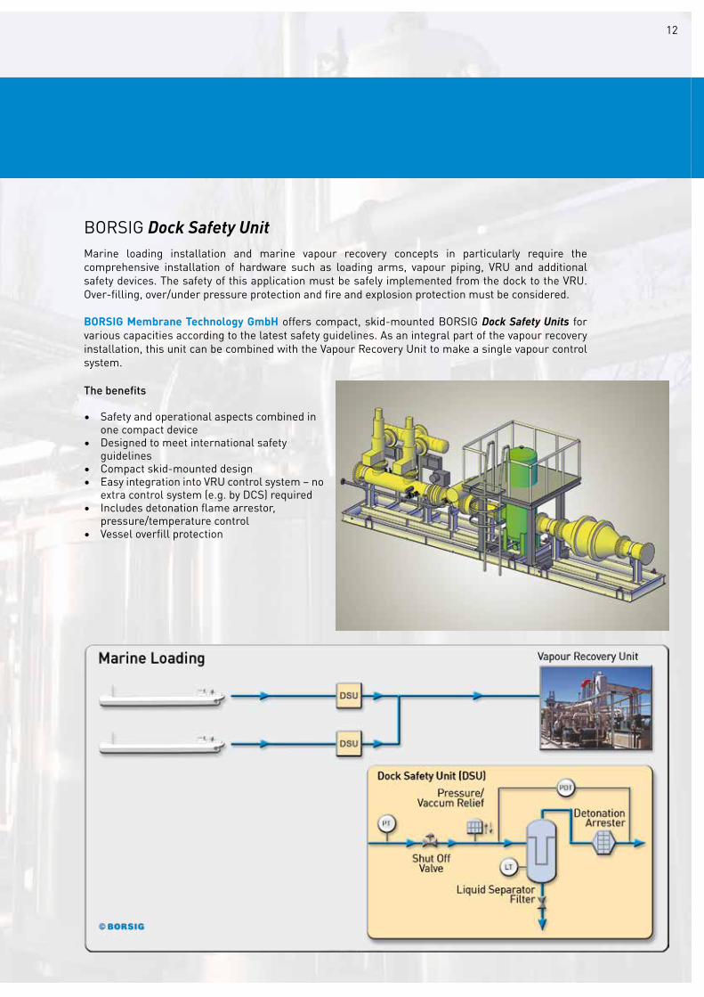
BORSIG Dock Safety UnitMarine loading installation and marine vapour recovery concepts in particularly require the comprehensive installation of hardware such as loading arms, vapour piping, VRU and additional safety devices. The safety of this application must be safely implemented from the dock to the VRU. Over-filling, over/under pressure protection and fire and explosion protection must be considered.
BORSIG Membrane Technology GmbH offers compact, skid-mounted BORSIG Dock Safety Units for various capacities according to the latest safety guidelines. As an integral part of the vapour recovery installation, this unit can be combined with the Vapour Recovery Unit to make a single vapour control system.
The benefits
• Safety and operational aspects combined in one compact device• Designed to meet international safety guidelines• Compact skid-mounted design• Easy integration into VRU control system – no extra control system (e.g. by DCS) required• Includes detonation flame arrestor, pressure/temperature control• Vessel overfill protection

2.3 Emission Control for
CAR FILLING STATIONS
13
Nowadays increasing local regulations require car filling stations to be entirely sealed to reduce leakage and prevent product loss that can impact on the environment and threaten safety.
There are three main sources of VOC emissions at car filling stations:
- Emissions caused by storage tank filling Typically these emissions can be minimised by Stage I measures which balance the vapours released while filling the underground storage tank from the truck.
- Emissions caused by car tank filling The emissions caused by released vapours from car tank can be reduced by a conventional Stage II vapour suction integrated in the filling nozzle which returns vapours to the storage tank. Sometimes limited efficiency of vapour collection affects the suction of air into the storage tank causing further evaporation of the storage product.
- Product vaporization Product vaporization causes an increase in tank pressure leading to emissions by pressure release via venting devices.
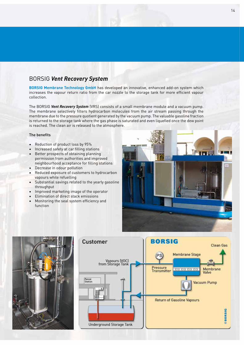
BORSIG Membrane Technology GmbH has developed an innovative, enhanced add-on system which increases the vapour return ratio from the car nozzle to the storage tank for more efficient vapour collection.
The BORSIG Vent Recovery System (VRS) consists of a small membrane module and a vacuum pump. The membrane selectively filters hydrocarbon molecules from the air stream passing through the membrane due to the pressure quotient generated by the vacuum pump. The valuable gasoline fraction is returned to the storage tank where the gas phase is saturated and even liquefied once the dew point is reached. The clean air is released to the atmosphere.
The benefits
• Reduction of product loss by 95%• Increased safety at car filling stations• Better prospects of obtaining planning permission from authorities and improved neighbourhood acceptance for filling stations• Decrease in odour pollution• Reduced exposure of customers to hydrocarbon vapours while refuelling• Substantial savings related to the yearly gasoline throughput• Improved marketing image of the operator• Elimination of direct stack emissions• Monitoring the seal system efficiency and function
14
BORSIG Vent Recovery System

2.4 Emission Control
REFERENCES
15

16

17
Product recovery systems must meet with ever more stringent efficiency requirements. Economic efficiency, productivity, improved sus-tainability of technological processes as well as optimum utilisation of our resources are key challenges for these types of systems.
BORSIG Membrane Technology GmbH offers optimum solutions which help to minimise losses, recover valuable raw materials or products from exhaust air, and process gas flows. The benefits are:
- Recovery of valuable feedstock and product- Significant reduction of waste and flare gas capacities- Reduction of emissions caused by waste gas treatment
Important products and applications include:
- Ethylene monomer from polyethylene (HDPE, LLDPE, etc.), EO or VAM production- Propylene monomer from polypropylene production- Solvent (e.g. hexane) from slurry-type HDPE production- Alkane recovery in polyethylene production- 1.3 butadiene from synthetic rubber production- Vinyl chloride monomer (VCM) from PVC production- Fluoro and chlorohydrocarbons from any related processes- Seal gas recovery for rotating machinery
PE Production• BORSIG Ethylene Recovery Unit• BORSIG Hydrocarbon Recovery Unit
PP Production• BORSIG Propylene Recovery Unit• BORSIG Nitrogen Recovery Unit
EO/EG Production• BORSIG Ethylene Recovery Unit
PVC and Rubber Production• BORSIG Monomer Recovery Unit
Seal Gas Recovery• BORSIG Seal Gas Recovery Unit
3.0 PRODUCT RECOVERY

18
3.1 Product Recovery for
PE PRODUCTION
19
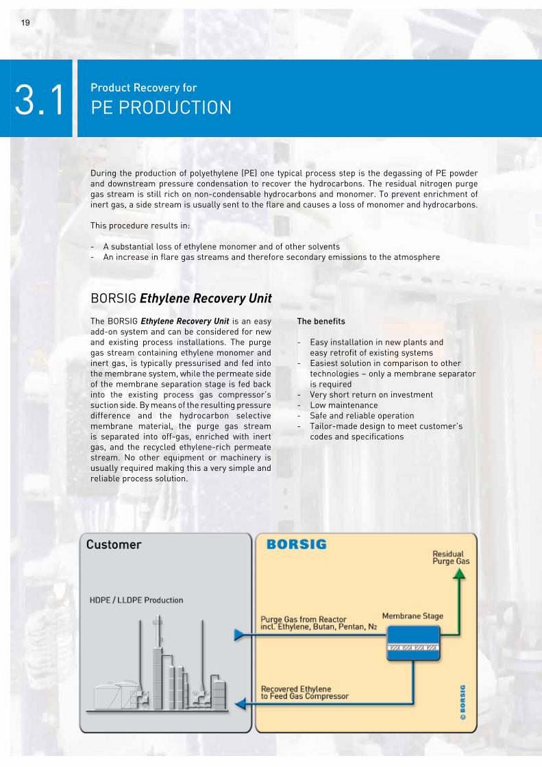
The BORSIG Ethylene Recovery Unit is an easy add-on system and can be considered for new and existing process installations. The purge gas stream containing ethylene monomer and inert gas, is typically pressurised and fed into the membrane system, while the permeate side of the membrane separation stage is fed back into the existing process gas compressor’s suction side. By means of the resulting pressure difference and the hydrocarbon selective membrane material, the purge gas stream is separated into off-gas, enriched with inert gas, and the recycled ethylene-rich permeate stream. No other equipment or machinery is usually required making this a very simple and reliable process solution.
The benefits
- Easy installation in new plants and easy retrofit of existing systems- Easiest solution in comparison to other technologies – only a membrane separator is required- Very short return on investment- Low maintenance- Safe and reliable operation- Tailor-made design to meet customer’s codes and specifications
BORSIG Ethylene Recovery Unit
During the production of polyethylene (PE) one typical process step is the degassing of PE powder and downstream pressure condensation to recover the hydrocarbons. The residual nitrogen purge gas stream is still rich on non-condensable hydrocarbons and monomer. To prevent enrichment of inert gas, a side stream is usually sent to the flare and causes a loss of monomer and hydrocarbons.
This procedure results in:
- A substantial loss of ethylene monomer and of other solvents- An increase in flare gas streams and therefore secondary emissions to the atmosphere

20
BORSIG Hydrocarbon Recovery UnitThe BORSIG Hydrocarbon Recovery Unit is a portfolio of specially developed and customised process solutions to meet emissions legislation and minimise the loss of product and profit by the recovery of valuable hydrocarbon. The membrane separation is combined with other unit operations such as absorption, condensation, extraction etc. These hybrid processes are very efficient and enable the customer to operate at the highest economic and ecological efficiency.A typical application is powder degassing in slurry-type PE plants. Polymer is flashed and
stripped with hot nitrogen and the released purge gas consisting of nitrogen and solvents like butane, pentane and hexane can be processed using a sophisticated BORSIG hydrocarbon recovery technology. The liquefied solvent and the purified nitrogen can be re-used. Another typical application is the vent gas from PE plants. The vent gas coming from the overhead of the upstream separator still contains a high amount of butane and pentane. The BORSIG Hydrocarbon Recovery Unit separates the butane and pentane from
the nitrogen before it is fed back to the suction side of the vent recovery compressor.
The benefits
- Flexible system for handling multiple components - Highest recovery rates and product purities at moderate pressures and temperatures- Safe operation, high reliability, low maintenance- Modular design to meet specific plant conditions and local regulations- Quick installation and easy implementation with package unit design- Adaptation to existing plants (retrofit design) feasible

3.2 Product Recovery for
PP PRODUCTION
21
The BORSIG Propylene Recovery Unit is an easy add-on system and can be considered for existing and new process installations. The purge gas stream is compressed and condensed in the downstream condenser stage being cooled with a cooling agent or liquid propylene. A degassing vessel downstream of the propylene separator may prove useful to reduce the amount of inert gases solved in the recovered propylene. The recovered propylene can be provided in a liquid or gaseous state at battery limit. For some PP production licenses an additional dryer system must be installed prior to condensation. After separating the condensate, the remaining purge gas is fed into the membrane system while the permeate side of the membrane separation stage is fed back to compressor’s suction side. By means of the resulting pressure difference and the hydrocarbon selective membrane material, the purge gas stream is separated into the purified nitrogen stream and the recycled propylene-
rich permeate stream. A small part of the separated stream is sent to the flare to prevent accumulation of lighter components. In some cases a hydrogen-selective membrane stage is used in order to meet the requirements of the highly purified nitrogen. In principal this stage is installed downstream of the hydrocarbon-selective membrane stage.
The benefits
- Recovery rates > 95% propylene and purity > 99 mol% nitrogen- Short return on investment periods (1-3 years)- Safe operation, high reliability, low maintenance- Tailor-made design - Quick installation and easy implementation by package unit design- Adaptation to existing plants (retrofit design) feasible
BORSIG Propylene Recovery UnitBORSIG Nitrogen Recovery Unit
The degassing of PP resin in the resin bin to purge non-reacted propylene monomer is a typical process step in the production of polypropylene (PP). Nitrogen is commonly used as a purge gas. Continuous purge streams containing substantial amounts of monomer need to be processed in order to minimise:- Loss of profit due to substantial loss of propylene monomer- Flare gas streams and therefore flare gas capacity and secondary emissions to the atmosphere

22

3.3 Product Recovery forEO/EG PRODUCTION
23
The benefits
- Many references for different licensors - High recovery rate- Quick installation and easy implementation by package unit design- Safe operation, high reliability, low maintenance- Short return on investment period
The BORSIG Ethylene Recovery Unit enables the recovery of valuable ethylene monomer from the cycle gas purge. Typically the purge gas first enters an inlet filter in order to remove droplets before entering the hydrocarbon-selective membrane stage. In the membrane stage ethylene is separated from argon and nitrogen. The ethylene-rich stream is routed to the suction side of the reclaim gas compressor whereas the ethylene-depleted stream is routed to the boiler unit.
The production of ethylene oxide (EO) is based on the catalyst-supported direct oxidation of oxygen with ethylene. Ethylene gas is converted to EO in the reactor and then the EO enters a cycle gas loop to be recycled back to the reactor by a compressor. A small amount of the cycle gas is purged continuously to prevent accumulation of inert components like argon and nitrogen. This purge gas contains a significant amount of valuable ethylene monomer which can be recovered by a membrane unit and recycled back to the cycle gas loop. This process can also be applied within vinyl acetate monomer (VAM) production.
BORSIG Ethylene Recovery Unit

24

3.4 Product Recovery for
PVC AND RUBBER PRODUCTION
25
The BORSIG Monomer Recovery Unit enables the recovery of valuable monomers in different applications. Depending on the upstream process, the membrane separation can be combined with unit operations such as compression, condensation, heating etc. Hydrocarbons are separated from mainly nitrogen in the membrane stage. The hydrocarbon enriched permeate stream is either routed to the process or the suction side of the compressor system inside the package unit in order to improve the overall condensation. In some cases an additional membrane stage is fitted in order to meet the requirements of highly purified nitrogen.
BORSIG Monomer Recovery Unit
In many petrochemical/chemical productions gaseous process streams are generated containing significant amounts of hydrocarbons such as vinyl chloride monomer (VCM) or 1.3-butadiene. Typically these hydrocarbons are mixed in inert gas streams and must be treated in order to:
- Meet off-gas conditions according to emissions legislation- Recover the valuable hydrocarbon content and therefore minimise the loss of product and profit- Meet the inlet conditions of any downstream process steps and systems
The benefits
- Flexible system for multiple components handling- Highest recovery rates and product purities- Moderate pressures and temperatures applied for required condensation- Safe operation, high reliability, low maintenance- Modular design to meet specific plant conditions and local regulations- Quick installation and easy implementation by package unit design- Adaptation to existing plants (retrofit design) feasible

26

3.5 Product Recovery for
SEAL GAS APPLICATIONS
27
The BORSIG Seal Gas Recovery Unit enables the valuable hydrocarbons to be recovered from the mechanical seal system. The process usually consists of the following unit operations: compression, condensation and membrane separation. The liquefied hydrocarbon is routed back to a tank for re-use in the ORC system and the nitrogen enriched exhaust gas is either routed to the flare system or can be purified in order to meet the nitrogen requirements for re-use in the process.
BORSIG Seal Gas Recovery Unit
An expansion device such as a turbine is used in Organic Rankine Cycles (ORC) to expand a working fluid such as propane, butane or organofluorine hydrocarbons. The expansion devices are typically equipped with a labyrinth mechanical seal system in order to prevent leakage. Nitrogen is used as a buffer gas injected inside the mechanical seal and mixed with the working fluid. The flow at the vent gas line, which is normally routed to the flare system, still contains of valuable hydrocarbons.
The benefits
- Flexible system for multiple component handling- Highest recovery rates and product purities- Safe operation, high reliability, low maintenance- Modular design to meet specific plant conditions and local regulations- Quick installation and easy implementation by package unit design- Adaption to existing plants (retrofit design) feasible
28
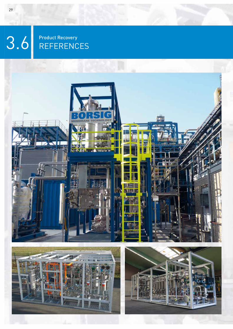
3.6 Product Recovery
REFERENCES
29

30

31
BORSIG Membrane Technology GmbH offers attractive process solutions for various gas separation applications in the fields of oil and gas production or refinery and process technology.
This covers the treatment of gas streams for conditioning raw gas flows, recovery of specific components and the improvement of product quality to comply with customer gas specifications.
Process concepts can be developed in addition to existing processes or as an alternative to conventional process solutions.
4.0 GAS SEPARATION
Products offered by BORSIG Membrane Technology GmbH in the field of gas separation are aimed at:
Hydrogen Separation• BORSIG Hydrogen Separation Unit
Fuel Gas Conditioning• BORSIG Fuel Gas Conditioning Unit

32
4.1 Gas Separation
HYDROGEN SEPARATION
33
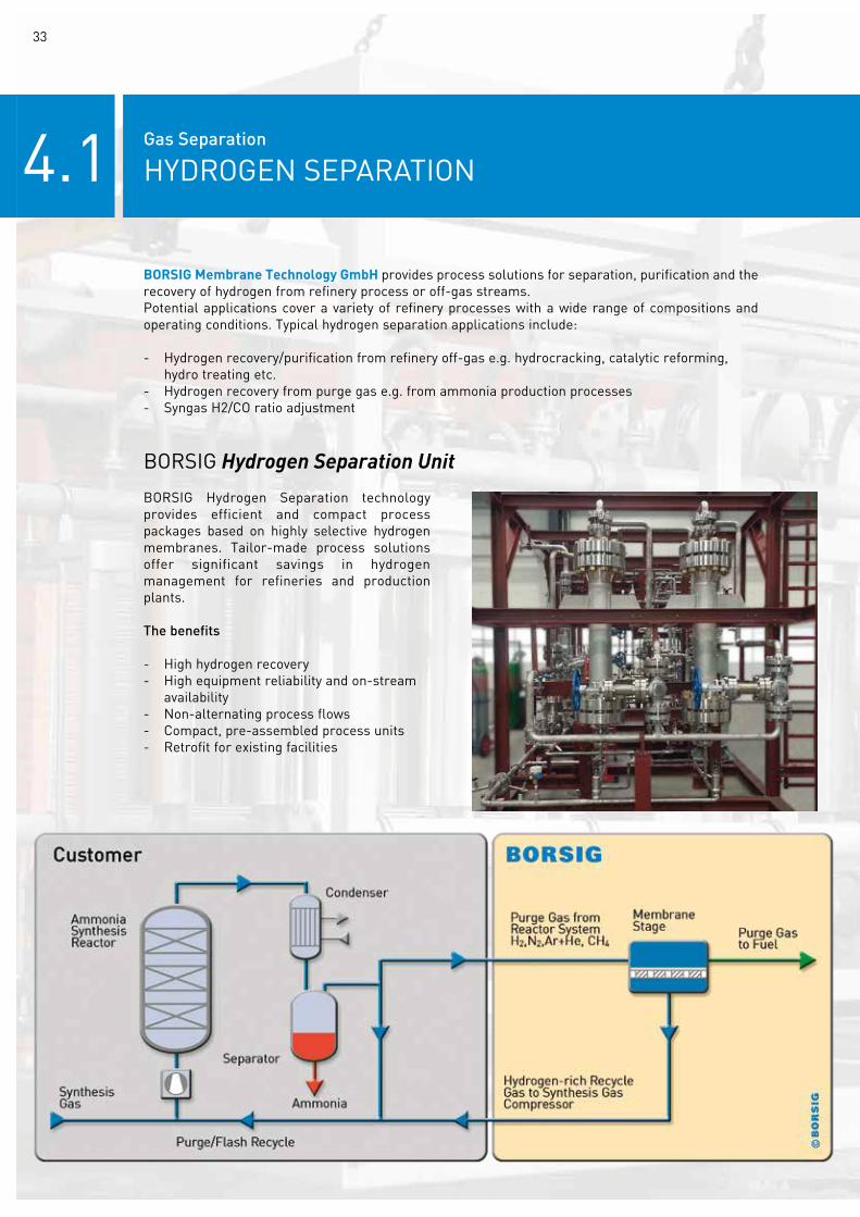
BORSIG Hydrogen Separation technology provides efficient and compact process packages based on highly selective hydrogen membranes. Tailor-made process solutions offer significant savings in hydrogen management for refineries and production plants.
The benefits
- High hydrogen recovery- High equipment reliability and on-stream availability- Non-alternating process flows- Compact, pre-assembled process units- Retrofit for existing facilities
BORSIG Hydrogen Separation Unit
BORSIG Membrane Technology GmbH provides process solutions for separation, purification and the recovery of hydrogen from refinery process or off-gas streams.Potential applications cover a variety of refinery processes with a wide range of compositions and operating conditions. Typical hydrogen separation applications include:
- Hydrogen recovery/purification from refinery off-gas e.g. hydrocracking, catalytic reforming, hydro treating etc.- Hydrogen recovery from purge gas e.g. from ammonia production processes- Syngas H2/CO ratio adjustment

34
4.2Gas Separation
FUEL GAS CONDITIONING
The fuel gas quality is specified in terms of minimum methane content, methane number, dew point or calorific value or other closely related parameters. These parameters are determined by the content of higher hydrocarbons in the fuel gas. The raw gas is typically taken out directly of a high pressure line on site or compressed by a separate compressor and routed to the membrane unit. The heavier hydrocarbons (C3+) are preferentially separated and concentrated on the low pressure side of the membrane. The lean residue, rejected by the membrane, provides high quality fuel gas.
BORSIG Fuel Gas Conditioning Unit
Fuel gas taken from the sources on-site and in particular in remote production locations often does not meet the high quality standards required for pipeline injection or for utilisation in modern high efficiency gas turbines or engines.
BORSIG Fuel Gas Conditioning technology provides a cost effective and highly reliable solution for gas treatment in order to enhance the gas quality for utilisation as a fuel gas for gas motors or to comply with pipeline specifications and requirements such as calorific-value or methane number.
The benefits
- High C3+ removal- High equipment reliability and on-stream availability- Compact, pre-assembled process units- Easy integration into existing facilities- Minimum supervision and maintenance - Prolonged life time of gas turbines or engines and related components- Particularly suitable for offshore applications and remote locations
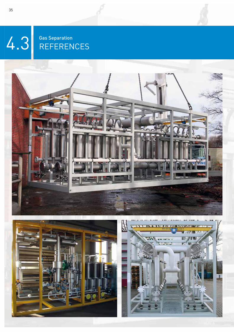
4.3 Gas Separation
REFERENCES
35

36

37
Saving energy, valuable resources and products is one of the highest priorities in the chemical and petrochemical industry today. While many membrane-based solutions for organic gas applications are state-of-art, organic liquid streams are typically processed by conventional thermal unit operations due to non-availability of solvent-resistant high performance membranes.In recent years BORSIG Membrane Technology GmbH has developed new solvent-resistant polymer membranes which are now industrially available having already proved their performance in industrial reference installations.These BORSIG membranes offer new and sophis-ticated liquid separation or fractionating processes for the treatment of organic mixtures and solvent-based production streams.
The BORSIG Membrane Technology product portfolio in the field of liquid separation includes:
• BORSIG Organic Solvent Nanofiltration (OSN) Unit• Products & services for OSN process development
5.0 LIQUID SEPARATION
38
5.1Liquid Separation
ORGANIC SOLVENT NANOFILTRATION
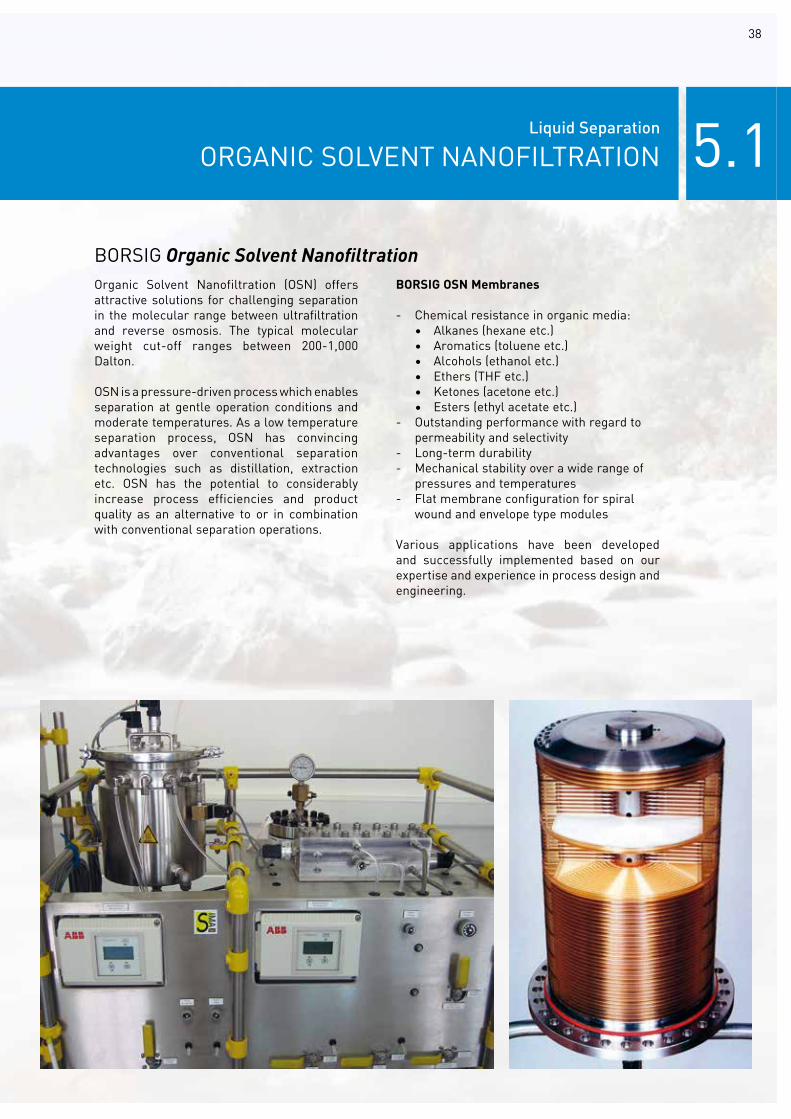
BORSIG OSN Membranes
- Chemical resistance in organic media: • Alkanes (hexane etc.) • Aromatics (toluene etc.) • Alcohols (ethanol etc.) • Ethers (THF etc.) • Ketones (acetone etc.) • Esters (ethyl acetate etc.)- Outstanding performance with regard to permeability and selectivity- Long-term durability- Mechanical stability over a wide range of pressures and temperatures- Flat membrane configuration for spiral wound and envelope type modules
Various applications have been developed and successfully implemented based on our expertise and experience in process design and engineering.
Organic Solvent Nanofiltration (OSN) offers attractive solutions for challenging separation in the molecular range between ultrafiltration and reverse osmosis. The typical molecular weight cut-off ranges between 200-1,000 Dalton.
OSN is a pressure-driven process which enables separation at gentle operation conditions and moderate temperatures. As a low temperature separation process, OSN has convincing advantages over conventional separation technologies such as distillation, extraction etc. OSN has the potential to considerably increase process efficiencies and product quality as an alternative to or in combination with conventional separation operations.
BORSIG Organic Solvent Nanofiltration

5.1 Liquid Separation
ORGANIC SOLVENT NANOFILTRATION
39
BORSIG Organic Solvent Nanofiltration Unit
The OSN membrane application faces two main challenges: the recovery or purification of solvents through the rejection of solutes and the recovery or concentration of solutes from a liquid dilution or solution.
The following uses of OSN have already been identified:
• Recovery of homogeneous catalysts from reaction mixtures• Conditioning of liquid hydrocarbons and fractionating of liquid process mixtures• Purification of organic solvents e.g. hexane• Concentration and purification of valuable fine chemicals • Recycling of used lube oil• De-colourisation of essential oils• OSN assisted crystallisation• Dewaxing of solvents
The principle of the OSN Unit is the cross flow over the membrane, dividing the inlet flow into solute enriched solvent upstream (concentrate) and purified solvent downstream (permeate).
In addition to the membrane stage the BORSIG Organic Solvent Nanofiltration Unit usually consists of a feed pump and a circulation pump. The feed pump pressurises the process fluid to the filtration pressure and the circulation pump maintains the required membrane cross flow.The mechanical design of the system is skid-mounted and pre-assembled for easy imple-mentation.
The benefits
• Moderate operation conditions (T, p) • Low energy consumption in comparison to thermal processes• No degradation of temperature sensitive natural compounds (low temperatures)• Improved product quality and yield• Easy and safe operation• Flexible capacity due to modular concept• Easy integration e.g. membrane-assisted distillation

40

41
5.1 Liquid Separation
ORGANIC SOLVENT NANOFILTRATION
Products & Services for OSN Process DevelopmentDue to complex interactions between the process fluids and the polymeric membranes, an intensive process development is required for OSN applications.

42
BORSIG Membrane Technology GmbH supports its customers in terms of suitable membrane and module type selection, provides technical assistance for laboratory tests as well as in terms of scale-up, and plant design.

5.2 Liquid Separation
REFERENCES
43

44

45
As a leading supplier of modern membrane process solutions, BORSIG Membrane Technology GmbH provides a complete range of lifecycle services covering all phases of a project. Starting with a general idea, we conduct a feasibility study, carry out engineering, installation and commissioning and provide a comprehensive after sales service as part of a beneficial customer partnership including:
• Comprehensive process knowledge• Data-based process simulation and low response time• Long-standing engineering expertise in petrochemical applications and knowledge of typical codes and standards• Lifecycle consulting services, trouble- shooting and process optimisation• Well-trained, multidiscipline engineers for new installations and service tasks• Remote 24/7 service team availability
6.0 SERVICE
BORSIG Membrane Technology GmbH offers the following lifecycle services:
• Feasibility studies/process simulation• Laboratory and field test• Basic and detailed engineering• After sales service

46

47
In order to provide our customers with the most efficient and economically attractive process concept for their applications, detailed evaluations with respect to process design and optimisation need to be carried out. The use of modern simulation programmes (e.g. Aspen HYSYS) in combination with our expertise in process and plant technology enable comprehensive optimisation of the overall process design. The simulation tools are an essential part of our project management allowing us to model the integration of the membrane separation unit into the client’s process and in combination with other unit operations.
Over the years BORSIG Membrane Technology GmbH has developed many innovative processes which have now become standard in many areas of petrochemistry and emission protection. In many cases our standard solutions have been integrated into relevant engineering packages by licensors or adapted again to the specific project conditions before a licence is granted.
It is often also necessary to develop a customised process solution to take into account the specific requirements of the customers process. Knowledge of the usual customer processes is therefore very important for understanding the interactions of the membrane system within the complete process and for evaluating the feasibility of a project.
Our staff has an excellent knowledge of the typical customer processes be it in the operation of storage terminals and refineries or the production of polymers on the basis of the broadest range of process licences.
6.1 Services
FEASIBILITY STUDIES / PROCESS SIMULATION

48
6.2Services
LABORATORY AND FIELD TEST
The process design for the main fields of application in the BORSIG Membrane Technology GmbH product portfolio is based on detailed process information and widespread experience in process evaluation and plant operation.
The characteristic parameters and optimal operating conditions for new applications with standard or newly developed membranes or client-specific processes are examined in our laboratories using professional test rigs. This enables us to determine membrane characteristics for each process and perform a thorough membrane screening prior to the design stage.
BORSIG Membrane Technology GmbH also possesses excellent expertise in the development and set-up of pilot and demonstration units and the operation of field tests. We offer comprehensive support in planning, operation and evaluation of pilot tests to our clients. Laboratory and field tests enable detailed process evaluation and determination of characteristic key figures as well as the optimisation of operating parameters as a design basis for the full-scale industrial process.

49
BORSIG Membrane Technology GmbH offers a comprehensive service package and individual support to its customers allowing them to concentrate on their core competences and tasks. This also means that we undertake significant engineering tasks ourselves and therefore always retain control over the project. Each individual stage is co-ordinated by an experienced project manager.
Our engineering team comprises experienced, highly qualified engineers and technicians who combine their years of experience with the latest engineering tools and programmes. This begins with process simulation using advanced
6.3 Services
BASIC & DETAIL ENGINEERING
process simulation software and continues with the construction of individualised equipment resulting in a final 3D model of the system.
Our staff consistently furthers their training making us an up-to-date, competent partner in the areas of process technology, construction, and measurement and control technology, and for specialised topics such as explosion protection.
In addition to the design and supply of complete systems, we also offer our customers individual engineering services for both new and existing systems.

50
6.4Services
AFTER SALES SERVICE
BORSIG Membrane Technology GmbH offers its customers in the oil and gas, refinery, tank farm and petrochemical industries complete service packages and individual services allowing to fully focus on their core competence.We follow each unit’s lifecycle in order to provide the best feasible service and maintenance based on our worldwide experience.Our service team is trained according to SCC and VCA and consists of experienced engineers and technicians in charge of plants and installations worldwide. We know what matters thanks to our years of experience in servicing industrial plants and our multidisciplinary competence in process engineering, plant design, control and instrumentation, and explosion protection.
We offer reliability, economic efficiency and protection for our customers assets. We can perform or co-ordinate all services ourselves and are hence capable of making optimum use of synergies. The basic requirement for optimum plant efficiency and the reduction of (non-scheduled) downtime is the regular inspection and functional check of all installation parts conducted by competent experts. Innovative measuring and analysis methods using software-supported and monitoring systems for fault analysis and maintenance and service scheduling help failures and breakdowns to be avoided. With these tools we are in the ideal situation to develop customised strategies with our clients for their particular application in order to establish timely service intervals for cost-saving maintenance. These made-to-measure concepts ensure that plant availability
and productivity increase, and environmental burdens and maintenance costs decreasesignificantly.
Our assets are:- After sales service, maintenance and trouble-shooting- Plant-specific maintenance contracts and spare part management systems- Maintenance and trouble-shooting of third-party vapour recovery units- 24/7 standby duty for intervention on demand with different reaction time levels- Remote service solution for fault analysis and software adjustment- Installation and commissioning of membrane systems such as VRU, PRU, HRU etc.- Basic and detailed engineering - Process control and visualisation - Operator training - Process development and optimisation- Hazard and operability studies (HAZOP) of BORSIG, third party VRUs and other plants and systems, IPF analysis- Process optimisation of existing plants and systems - Performance tests of BORSIG and third party plants and systems, including emissions and capacity measurement, gas analysis, active carbon analysis- Official emission measurements in co-operation with authorities according to different European standards- Emission reports for refineries and tank farms- Pressure vessel tests in co-operation with authorities

BORSIG MEMBRANE TECHNOLOGY GMBH - 01/2019
BORSIG Membrane Technology GmbHOffice North Office South Bottroper Str. 279 Am Rhein 5 45964 Gladbeck / Germany 79618 Rheinfelden/Germany
Phone +49 (0) 2043 / 4006-01 Phone +49 (0) 7623 / 96609-0 Fax +49 (0) 2043 / 4006-6299 Fax +49 (0) 7623 / 96609-50
E-mail: [email protected]