biomerieux mini vidas - user manual
DESCRIPTION
Mini Vidas User's ManualTRANSCRIPT

mini VIDAS ®
Procedures Manual
bioMérieux S.A. 69280 Marcy l'Etoile / France Tel. 33 (0)4 78 87 20 00 - Fax 33 (0)4 78 87 20 90
http://www.biomerieux.com
Printed in France / 673 620 399 RCS Lyon
REF 99188 version F 07/2008
© 1996-2008. bioMérieux, S.A.
4501
- 17
21 e
n

4501-1584 E en
Argentina bioMérieux Argentina Av. Congreso 1745 (C1428BUE) Capital Federal Buenos Aires tel. (54) 11 5555-6800 fax (54) 11 5555-6888 Australia bioMérieux Australia P/L Unit 25, Parkview Business Center 1 Maitland Place Baulkham Hills NSW 2153 tel. (61) 2 8852 4700 fax (61) 2 8852 4777 Austria bioMérieux Austria GmbH Eduard-Kittenberger-Gasse 97 Top 3 A-1230 Wien tel. (43) 186 50 650 fax (43) 186 50 661 Belgium bioMérieux Benelux s.a./n.v. Media Square 18-19 Place des Carabiniers Bruxelles 1030 tel. (32) 2 743 01 70 fax (32) 2 733 55 97 Brazil bioMérieux Brasil SA Estrada Do Mapua 491 Taquara - Jacarepaguá CEP 22710 261 Rio de Janeiro R.J Rio de Janeiro R.J tel. (55) 21 2444 1400 fax (55) 21 2445 6025 Canada bioMérieux Canada, Inc. 7815, Henri-Bourassa West Saint Laurent, QC H4S 1P7 tel. (1) 514 336 7321 fax (1) 514 807 0015 Chile bioMérieux Chile S.A. Seminario 131 Providencia Santiago tel. (56) 2634 20 92 fax (56) 2634 20 93
China bioMérieux China Limited Room 1601-02B & 10 Est Ocean Centre n° 24A Jiang Guo Men Nei Street, 100004 Beijing tel. (86) 10 6515 6963 fax (86) 10 6515 6993 bioMérieux China Limited Room 2605, South Tower, World Trade Center 371-375 Huan Shi Dong East Road 510095 Guangzhou tel. (86) 20 8762 7010 fax (86) 20 8762 7015 Colombia bioMérieux Colombia Ltda Avenida 15 No. 100-43 Piso 2 Bogotá D.C. tel. (57) 1 520 0080 fax (57) 1 520 0088 / 1 520 0831 Czech republic bioMérieux CZ s.r.o. Business Park Kosice, Jinonická 80 158 00 Praha 5 tel. (420) 2 57 290 623 / (420) 2 57 290 232 fax (420) 2 57 290 964 Denmark bioMérieux Danmark Aps Smedeholm 13C, 2730 Herlev tel. (45) 70 10 84 00 fax (45) 70 10 84 01 Finland bioMérieux Suomi Oy Konalantie 47 C FI-00390 Helsinki tel. (358) 9 8545 6000 fax (358) 9 8545 6045 France bioMérieux S.A. 69280 Marcy l’Etoile tel. 33 (0)4 78 87 20 00 fax 33 (0)4 78 87 20 90 http://www.biomerieux.com Germany bioMérieux Deutschland GmbH Weberstrasse 8 D-72622 Nürtingen tel. (49) 7022 30070 fax (49) 7022 36110
Greece bioMérieux Hellas S.A. Papanikoli 70 15232 Halandri Athens tel. (30) 210 81 72 400 fax (30) 210 68 00 880 Hungary bioMérieux Hungária Kft. Fóti út. 56 (5th Floor) H-1047 Budapest tel. (36) 1 231 3050 fax (36) 1 231 3059 India bioMérieux India Pvt. Ltd A-32, Mohan Co-Operative Ind. Estate New Delhi 110 024 tel. (91) 11 42 09 88 00 fax (91) 11 24 64 88 30 Indonesia Representation office bioMérieux Indonesia Enseval Building Kawasan Industri Pulo Gadung - JI. Pulo Lentut No. 10 Jakarta Timur 13920 tel. (62) 21 461 51 11 fax (62) 21 460 41 07 Italy bioMérieux Italia S.p. A Via Fiume Bianco, 56 00144 Roma tel. (39) 0 6 523081 fax (39) 0 6 52308240 Ivory Coast bioMérieux Afrique Occidentale 08 BP 2634 Abidjan 08 tel. (225) 22 40 93 93 / (225) 22 40 41 40 fax (225) 22 40 93 94 Japan bioMérieux Japan, Ltd Seizan Bldg., 12-28 Kita-Ayoama 2-chome Minato-ku, Tokyo 107-0061 tel. (81) 3 5411 87 11 fax (81) 3 5411 87 10 Korea bioMérieux Korea Co., Ltd 1st & 2nd Floor, Yoosung Building # 830-67 Yoksam-dong, Kangnam ku Seoul 135-080 tel. (82) 2 2188 4700 fax (82) 2 547 6263

Mexico bioMérieux México SA de CV Chihuahua 88, col. Progreso México 01080, D.F. tel. (52) 55 5481 9550 fax (52) 55 5616 2245 Netherlands (The) bioMérieux Benelux BV Boseind 15 P.O. Box 23 5280 AA Boxtel tel. (31) 411 65 48 88 fax (31) 411 65 48 73 New Zealand bioMérieux New Zealand Ltd C/- Logical Freight Solutions 12 C Rennie Drive, Airport Oaks Auckland tel. (64) 9 918 6354 fax (64) 9 918 6355 Norway bioMérieux Norge AS ∅kernveien 145 N - 0513 Oslo tel. (47) 23 37 55 50 fax (47) 23 37 55 51 Philippines (The) Representation office bioMérieux Philippines Rep. Office 11th Floor, Pearlbank Centre 146 Valero Street, Salcedo Village 1227 Makati City tel. (632) 817 7741 fax (632) 812 0896 Poland bioMérieux Polska Sp. Z.o.o. ul. Zeromskiego 17 01-882 Warsaw tel. (48) 22 569 85 00 fax (48) 22 569 85 54
Portugal bioMérieux Portugal, Lda. Av. 25 de Abril de 1974, nº 23 – 3º 2795-197-LINDA-A-VELHA tel. (351) 21 415 23 50 fax (351) 21 418 32 67 Russia o.o.o. bioMérieux Derbenevskaya ul. 20, str. 11 115 114 Moscow tel. (7) 495 221 10 79 fax (7) 495 221 10 79 Spain bioMérieux España S.A. Manual Tovar, 45-47 28034 Madrid tel. (34) 91 358 11 42 fax (34) 91 358 06 29 Sweden bioMérieux Sverige AB Hantverksvägen 15 436 33 Askim tel. (46) 31 68 84 90 fax (46) 31 68 48 48 Switzerland bioMérieux Suisse s.a. 51, avenue Blanc Case postale 2150 1211 Genève 2 tel. (41) 22 906 57 60 fax (41) 22 906 57 42 Taiwan Representation office bioMérieux China Limited - Taiwan Branch RM 608, No. 6-3 Ching Cheng Street Taipei 105 tel. (886) 2 2545 2250 fax (886) 2 2545 0959
Thaïland bioMérieux Thaïland Ltd Regent House Bldg, 16 th Floor 183 Rajdamri Road, Lumpini, Pathumwan Bangkok 10330 tel. (66) 2 651 98 00 fax (66) 2 651 98 01 Turkey bioMérieux Diagnostik A.S. Değirmen Sok. Nida Plaza Kat:6 34742 Kozyataği / Istanbul tel. (90) 216 444 00 83 fax (90) 216 373 16 63 United Kingdom bioMérieux UK Ltd Grafton Way, Basingstoke Hampshire RG22 6HY tel. (44) 1256 461881 fax (44) 1256 816863 USA bioMérieux, Inc. 100 Rodolphe Street Durham NC 27712 tel. (1) 919 620 20 00 fax (1) 919 620 22 11 Vietnam Representation office bioMérieux (Thailande) Ltd. Rep. Office in Vietnam Room 4A, 4th Floor Green House Building 62A Pham Ngoc Thach Street, Ward 6 District 3 Ho Chi Minh City tel. (84) 88 209 906 fax (84) 88 209 905
Distribution in over 130 countries
mini VIDAS® Procedures Manual Revisions-1
Revis ions
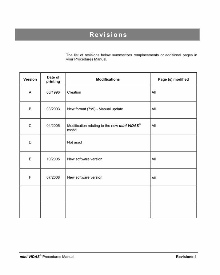
The list of revisions below summarizes remplacements or additional pages in your Procedures Manual.
Version Date of printing Modifications Page (s) modified
A 03/1996 Creation All
B 03/2003 New format (7x9) - Manual update All
C 04/2005 Modification relating to the new mini VIDAS® model
All
D Not used
E 10/2005 New software version All
F 07/2008 New software version All


4501-1618 A en
The content of this manual is based on the Software release 5.3.0. This manual is periodically updated. The updates shall be included in the new releases of the Software. Information supplied in this manual may be subject to modifications before the products described become available. This manual may contain information or references relating to certain bioMérieux S.A. products, software or services which are not available in the country of release; this shall not mean that bioMérieux S.A. intends to market such products, software or services in such country To request copies of publications or for any technical request, contact bioMérieux S.A. or your local distributor.
L i a b i l i t y d i s c l a i m e r THIS MANUAL IS PROVIDED "AS IS" WITHOUT ANY WARRANTY, EITHER EXPRESS OR IMPLIED, OF MERCHANTABILITY, SAFETY, QUALITY, ACCURACY OR THE PERFORMANCE OF PRODUCTS DESCRIBED IN THIS MANUAL. IN ADDITION, THERE SHALL BE NO IMPLIED WARRANTY OF MERCHANTABILITY OR FITNESS FOR A PARTICULAR PURPOSE, NOR NON INFRINGEMENT OF THIRD PARTIES' INTELLECTUAL PROPERTY RIGHTS. In no event shall bioMérieux S.A. be liable for any direct, consequential, incidental or indirect damage or consequence related to, arising out of or in connection with, any use of this manual and/or its results by the User and/or any third party. In no event shall this manual be construed as an undertaking of bioMérieux S.A. bioMérieux S.A. reserves the right to modify this manual without notice and shall incur no liability as a result of such modification. This manual is provided for information purposes only.
I n t e l l e c t u a l P r o p e r t y bioMérieux S.A. is the sole owner of copyright, patrimonial rights and any other intellectual property rights in and to this manual and its content, except for the potential third parties' rights.This manual and its content are protected under the provisions of section L.111-1 and following articles of the French Intellectual Property Code and International Copyright and Author Rights Treaties. The rights to use this manual granted herein are non-exclusive and limited to the extent necessary to use the Software and Instrument. In no event shall the Users be granted any other right to use this manual including without limitation, the right to reproduce, represent, adapt or translate all or part of this manual by any means whatsoever without the prior written consent of bioMérieux S.A. Any use of this manual other than expressly permitted hereunder may be prosecuted.
IMPORTANT! USE OF THIS MANUAL CONSTITUTES ACCEPTANCE OF THE TERMS AND CONDITIONS SET FORTH HEREIN.

bioMérieux, the blue logo and mini VIDAS are used, pending and/or registered trademarks belonging to bioMérieux S.A. or one of its subsidiaries. Dacron is a used, pending and/or registered trademark belonging to Invista North America, SARL. 7X is a used, pending and/or registered trademark belonging to MP Biomedicals, LLC. Alconox and Liquinox are used, pending and/or registered trademarks belonging to Alconox, Inc.
4501-1577 A en
SOFTWARE L ICENSE AGREEMENT
User: No.: Software: Release: Computer: Brand name: Printer: Brand name: Disk player: Brand name:
IMPORTANT! The use of this Software is strictly governed by the following terms and conditions.
I – Purpose of th is Agreement / Rights granted bioMérieux S.A. hereby grants, to the User who, by using this manual, accepts a non-exclusive right to use the Software. The license is personal, non transferable, non assignable and does not comprise the right to grant sub-licenses. The User expressly agrees, in its own name and behalf as well as in the name and on behalf of its employees, agents and collaborators, not to make any copy of the Software-except one single backup copy for archival purposes- display the Software on any computer other than the Computer, reproduce, sell, rent, lease, modify, adapt, translate or otherwise dispose of, all or part of the Software, the equipment, the user manual and its related documentation. Specifically, the User agrees not to decompile, reverse engineer or disassemble all or part of the Software.
I I – Intel lectual Property All intellectual property rights including patrimonial rights, in and to the Software are and shall remain bioMérieux S.A. exclusive property, subject to possible third party rights. Consequently, the User is not entitled to copy or reproduce the Software except as set forth above. Except as expressly specified above, nothing contained herein shall be construed as conferring to the User any right, title or interest in and to the Software.
I I I – Warrant ies Provided that this Agreement duly signed is received by bioMérieux S.A. within ten (10) business days from the delivery, bioMérieux S.A. warrants that the Software is free from defect in materials and workmanship under normal conditions of use during three (3) months from the delivery. Should any defect occur during such period, bioMérieux S.A. or one of its authorized distributors in the country of sale shall replace the Software provided that the User makes its request in writing together with copy of the Software invoice and, as the case may be, the defective media. Apart from the foregoing, the Software is provided "AS IS" and no warranty, whether express or implied, of merchantability, safety, quality, or fitness for a particular purpose is given hereunder nor any warranty that the Software shall not infringe upon the intellectual property rights of any third party

The warranty provided herein shall apply provided that Software is used under normal conditions and to the exclusion of any replacement caused by accidental or willful damage, or misuse of the software or accident whatsoever. It is expressly understood that, according to this License, bioMérieux S.A. shall not perform any service related to the training, assistance or maintenance of the Software unless otherwise agreed upon between the parties through a separate written agreement setting forth the terms and conditions (in particular, financial conditions) of such training, assistance or maintenance.
IV – Liabi l i ty In no event shall bioMérieux S.A. be liable for consequences related to, arising out of or in connection with, modifications of Software by anyone other than bioMérieux S.A. In no event shall bioMérieux S.A. be liable for any direct, indirect, special, consequential, incidental or material damage (including loss of goodwill, profits, data or any other economic advantage) related to, arising out of or in connection with, any use of the Software and/or its results by the User and/or any third party, including without limitation, its clients, customers and sub-contactors. User hereby agrees to indemnify, defend and hold bioMérieux S.A. harmless from all claims, damages, expenses, suits, losses or liabilities relating to, arising out of or in connection with User or such parties as well for any action of such third parties against bioMérieux S.A. Should this provision be held unenforceable or void, the User irrevocably agrees that bioMérieux S.A. liability and expenses for all causes shall not exceed the total amount actually paid by the User hereunder for the software release concerned by the claim.
V – Appl icable Law and set t lement of d isputes This agreement is governed and construed in accordance with French Law. Parties shall make their best efforts to settle any dispute through amicable discussions. In the event no amicable settlement is reached in the period of three (3) months after communication of the claim, any litigation shall be held in the exclusive jurisdiction of the courts of Lyon, France. Done.............................................................................. This…….....................day of ......................................... Signature and User's stamp: COPY TO BE RETURNED TO BIOMERIEUX S.A.
4501-1577 A en
SOFTWARE L ICENSE AGREEMENT
User: No.: Software: Release: Computer: Brand name: Printer: Brand name: Disk player: Brand name:
IMPORTANT! The use of this Software is strictly governed by the following terms and conditions.
I – Purpose of th is Agreement / Rights granted bioMérieux S.A. hereby grants, to the User who, by using this manual, accepts a non-exclusive right to use the Software. The license is personal, non transferable, non assignable and does not comprise the right to grant sub-licenses. The User expressly agrees, in its own name and behalf as well as in the name and on behalf of its employees, agents and collaborators, not to make any copy of the Software-except one single backup copy for archival purposes- display the Software on any computer other than the Computer, reproduce, sell, rent, lease, modify, adapt, translate or otherwise dispose of, all or part of the Software, the equipment, the user manual and its related documentation. Specifically, the User agrees not to decompile, reverse engineer or disassemble all or part of the Software.
I I – Intel lectual Property All intellectual property rights including patrimonial rights, in and to the Software are and shall remain bioMérieux S.A. exclusive property, subject to possible third party rights. Consequently, the User is not entitled to copy or reproduce the Software except as set forth above. Except as expressly specified above, nothing contained herein shall be construed as conferring to the User any right, title or interest in and to the Software.
I I I – Warrant ies Provided that this Agreement duly signed is received by bioMérieux S.A. within ten (10) business days from the delivery, bioMérieux S.A. warrants that the Software is free from defect in materials and workmanship under normal conditions of use during three (3) months from the delivery. Should any defect occur during such period, bioMérieux S.A. or one of its authorized distributors in the country of sale shall replace the Software provided that the User makes its request in writing together with copy of the Software invoice and, as the case may be, the defective media. Apart from the foregoing, the Software is provided "AS IS" and no warranty, whether express or implied, of merchantability, safety, quality, or fitness for a particular purpose is given hereunder nor any warranty that the Software shall not infringe upon the intellectual property rights of any third party.

The warranty provided herein shall apply provided that Software is used under normal conditions and to the exclusion of any replacement caused by accidental or willful damage, or misuse of the software or accident whatsoever. It is expressly understood that, according to this License, bioMérieux S.A. shall not perform any service related to the training, assistance or maintenance of the Software unless otherwise agreed upon between the parties through a separate written agreement setting forth the terms and conditions (in particular, financial conditions) of such training, assistance or maintenance.
IV – Liabi l i ty In no event shall bioMérieux S.A. be liable for consequences related to, arising out of or in connection with, modifications of Software by anyone other than bioMérieux S.A. In no event shall bioMérieux S.A. be liable for any direct, indirect, special, consequential, incidental or material damage (including loss of goodwill, profits, data or any other economic advantage) related to, arising out of or in connection with, any use of the Software and/or its results by the User and/or any third party, including without limitation, its clients, customers and sub-contactors. User hereby agrees to indemnify, defend and hold bioMérieux S.A. harmless from all claims, damages, expenses, suits, losses or liabilities relating to, arising out of or in connection with User or such parties as well for any action of such third parties against bioMérieux S.A. Should this provision be held unenforceable or void, the User irrevocably agrees that bioMérieux S.A. liability and expenses for all causes shall not exceed the total amount actually paid by the User hereunder for the software release concerned by the claim.
V – Appl icable Law and set t lement of d isputes This agreement is governed and construed in accordance with French Law. Parties shall make their best efforts to settle any dispute trough amicable discussions. In the event no amicable settlement is reached in the period of three (3) months after communication of the claim, any litigation shall be held in the exclusive jurisdiction of the courts of Lyon, France. Done.............................................................................. This…….....................day of ......................................... Signature and User's stamp:
COPY TO BE KEPT BY USER

Genera l Warn ings
DANGER! All biological fluids should be considered as potentially infectious.
Protective gloves must be worn when manipulating blood, products derived from blood or objects contaminated with blood.
Qualified laboratory personnel should use acceptable procedures for biohazardous material.
WARNING! The configuration that you have purchased is adapted to the legislation and standards of the different countries it will be sent to. For this reason, it may differ from the one presented in this document. However it will not prevent mini VIDAS from operating correctly. This product is an in vitro diagnostic medical device. It complies with the directives and standards mentioned in the certificate supplied with it.
IMPORTANT ! Read this manual carefully to obtain optimum performance from your mini VIDAS. bioMérieux SA recommends that you observe the different warnings inscribed on the instrument itself and indicated in the documentation supplied. The accuracy of results obtained with this instrument depends, in particular, on the maintenance operations described in this manual. The user should be aware that, if the maintenance operations are not performed, are only partially performed, or are not performed as described in this manual, bioMérieux SA is in no case liable for any false test results obtained.

WARNING! bioMérieux SA is in no case liable for any changes made to the equipment without authorization from bioMérieux SA. Electromagnetic Compatibility (EMC): This is a Class A product. In a residential area, this product may cause harmful interference in which case the user may be required to take adequate measures at his own expense. The equipment may also cause inteference if not installed in accordance with the instructions given in this manual. Never download into the computer, programs other than those provided by bioMérieux SA. If these instructions are not complied with, the computer could become infected with computer viruses. Any intervention directly or indirectly resulting from the presence of such a virus cannot be covered by the warranty or the maintenance contract.
This statement only applies to the EC and instruments bearing the
symbol with regard to the waste electrical and electronic equipment.
You can play an important role in contributing to reuse, recycling and other forms of recovery of waste electrical and electronic equipment. Sorting this type of waste significantly reduces potential negative effects on the environment and human health as a result of the presence of hazardous substances in electrical and electronic equipment.
At the end of the life cycle of this product, do not dispose of the product as unsorted municipal waste, even if it is decontaminated. It is imperative that you contact bioMérieux to assure for its appropriate disposal.

mini VIDAS® Procedures Manual V-1
Tab le of contents
1 How to use this manual..................................................................................................................... 1-1 Finding topics or procedures................................................................................................................ 1-2 Typographic conventions ..................................................................................................................... 1-4 The mini VIDAS keypad....................................................................................................................... 1-4 Graphic symbols .................................................................................................................................. 1-6
2 Parts of the mini VIDAS ..................................................................................................................... 2-1 The mini VIDAS hardware ................................................................................................................... 2-2
Sections ......................................................................................................................................... 2-3 Reagent strip tray ..................................................................................................................... 2-3 SPR® block ............................................................................................................................... 2-4 Operating status light................................................................................................................ 2-4 Microprocessor ......................................................................................................................... 2-4 Incubators................................................................................................................................. 2-4 Strip preparation tray ................................................................................................................ 2-5
Detection system............................................................................................................................ 2-6 Central processing unit................................................................................................................... 2-6 Keypad and screen ........................................................................................................................ 2-6 Internal printer ................................................................................................................................ 2-7 Rear panel components ................................................................................................................. 2-8 Bar code readers.......................................................................................................................... 2-10
Recommendations for use of the bar code reader.................................................................. 2-10 Possibilities of extension.................................................................................................................... 2-11 The mini VIDAS software................................................................................................................... 2-12
The mini VIDAS menus ................................................................................................................ 2-12 Selecting a menu option ......................................................................................................... 2-13 Menu structure........................................................................................................................ 2-14
The status screen......................................................................................................................... 2-15 The first status screen ............................................................................................................ 2-15 The second status screen....................................................................................................... 2-18 The third status screen ........................................................................................................... 2-19
Online help ................................................................................................................................... 2-20 Viewing error messages............................................................................................................... 2-21 Screen paging .............................................................................................................................. 2-21
Paging bar .............................................................................................................................. 2-22 Memory cards............................................................................................................................... 2-23
The assay kit...................................................................................................................................... 2-24 Single reagent strip ...................................................................................................................... 2-24 Dual reagent strip ......................................................................................................................... 2-25 The label ...................................................................................................................................... 2-25 The SPR....................................................................................................................................... 2-27
How the SPR functions........................................................................................................... 2-28
Table of contents
V-2 mini VIDAS® Procedures Manual
3 Getting started ................................................................................................................................... 3-1 Aim / Description.................................................................................................................................. 3-2 Precautions for installation and use ..................................................................................................... 3-3 Unpacking the mini VIDAS................................................................................................................... 3-5
Preparations before unpacking....................................................................................................... 3-5 Starting the mini VIDAS ....................................................................................................................... 3-7 Shutting down the mini VIDAS ........................................................................................................... 3-10 Configuring the mini VIDAS ............................................................................................................... 3-11
Setting dose units......................................................................................................................... 3-12 Setting user ID.............................................................................................................................. 3-14 Setting user ID.............................................................................................................................. 3-14 Setting the report header.............................................................................................................. 3-16 Setting the report header.............................................................................................................. 3-16 Setting the date and time.............................................................................................................. 3-17 Setting display contrast ................................................................................................................ 3-18 Selecting the printer ..................................................................................................................... 3-19 Setting the date/time format ......................................................................................................... 3-20 Defining the sample ID character sets.......................................................................................... 3-23 Changing the keyclick volume ...................................................................................................... 3-25 Changing the beep volume........................................................................................................... 3-26 Error beeps................................................................................................................................... 3-27
Setting initial error volume ...................................................................................................... 3-27 Setting the final error volume.................................................................................................. 3-28
Enabling display blinking .............................................................................................................. 3-29 Miscellaneous items ..................................................................................................................... 3-30 LIS user options ........................................................................................................................... 3-34 Creating normal ranges for assays............................................................................................... 3-36
Installing paper in the printer.............................................................................................................. 3-38 Print screen........................................................................................................................................ 3-40
4 Routine procedures ........................................................................................................................... 4-1 Precautions for use of reagents ........................................................................................................... 4-2
Specificities of the mini VIDAS blue .......................................................................................... 4-2 Basic mini VIDAS work flow ................................................................................................................. 4-3 Planning a run...................................................................................................................................... 4-8
Type of run required ....................................................................................................................... 4-8 Defined vs. load and go runs .................................................................................................... 4-8
Assay compatibility ......................................................................................................................... 4-9 Standards and controls................................................................................................................. 4-10
Standards ............................................................................................................................... 4-10 Controls .................................................................................................................................. 4-10
Summary of the mini VIDAS software .......................................................................................... 4-11

Table of contents
mini VIDAS® Procedures Manual V-3
Running assays ................................................................................................................................. 4-13 Assay requests............................................................................................................................. 4-13 Starting a load and go run ............................................................................................................ 4-13 Starting a defined run ................................................................................................................... 4-16 Assigning a dilution factor ............................................................................................................ 4-24
Calibration – Recalibration................................................................................................................. 4-27 Principles of calibration using the mini VIDAS.............................................................................. 4-27
Theoretical principle................................................................................................................ 4-27 Principle applied to mini VIDAS .............................................................................................. 4-28
Principles of recalibration using mini VIDAS ................................................................................ 4-29 Theoretical principle................................................................................................................ 4-29 Principle of use ....................................................................................................................... 4-29 Establishing the master curve................................................................................................. 4-31
How to calibrate............................................................................................................................ 4-32 Master Lot data– Principle of calibration................................................................................. 4-32 Procedure ............................................................................................................................... 4-32
Entering master lot data..................................................................................................................... 4-33 Automatic entry via the Master Lot Entry (MLE) card ................................................................... 4-34
Error reading the card............................................................................................................. 4-36 Manual master lot data entry (option 2)........................................................................................ 4-37
Case 1 .................................................................................................................................... 4-37 Case 2 .................................................................................................................................... 4-40
Listing stored standards..................................................................................................................... 4-43 Listing master lots .............................................................................................................................. 4-45 Halting a section ................................................................................................................................ 4-46
5 Results and reports ........................................................................................................................... 5-1 Analysis methods................................................................................................................................. 5-1
Terminology ................................................................................................................................... 5-2 Qualitative assays: single reagent strips ........................................................................................ 5-3 Qualitative assays: dual reagent strips........................................................................................... 5-4 Quantitative assays ........................................................................................................................ 5-5
The assay report .................................................................................................................................. 5-6 Qualitative assays: single reagent strip .......................................................................................... 5-8 Qualitative Assays: dual reagent strip ............................................................................................ 5-9 Quantitative assays ...................................................................................................................... 5-10
Assay report errors ............................................................................................................................ 5-11 Reprinting an assay report ................................................................................................................. 5-12 Validating LIS results ......................................................................................................................... 5-15 Printing the mini VIDAS assay list...................................................................................................... 5-18

Table of contents
V-4 mini VIDAS® Procedures Manual
6 Miscellaneous operations ................................................................................................................. 6-1 Taking a section off line ....................................................................................................................... 6-2 Changing factory settings..................................................................................................................... 6-3
Accessing the factory settings ........................................................................................................ 6-3 Selecting a language...................................................................................................................... 6-5
Testing the mini VIDAS instrument ...................................................................................................... 6-7 Accessing the tests ........................................................................................................................ 6-7 Testing the display ......................................................................................................................... 6-7
Decrease in the intensity of display .......................................................................................... 6-7 Testing the keypad ......................................................................................................................... 6-8 Testing the printer .......................................................................................................................... 6-9 Testing the audio output ................................................................................................................. 6-9
Updating an assay ............................................................................................................................. 6-10 Purpose of the assay update........................................................................................................ 6-10 Updating ....................................................................................................................................... 6-10
Preliminary instructions........................................................................................................... 6-10 Reading assay update card bar codes ................................................................................... 6-11
Displaying the mini VIDAS software version ...................................................................................... 6-15 Printing the mini VIDAS software version........................................................................................... 6-16 Displaying the assay version.............................................................................................................. 6-17 Section counters ................................................................................................................................ 6-19 Printing the assay version .................................................................................................................. 6-20 Updating the mini VIDAS software via the memory card.................................................................... 6-21 Verifying the memory card data ......................................................................................................... 6-24 Shipping the mini VIDAS.................................................................................................................... 6-25
7 Error handling .................................................................................................................................... 7-1 The error message alert system .......................................................................................................... 7-2
Responding to an error alert........................................................................................................... 7-2 Types of error message screens .................................................................................................... 7-3
Start errors ........................................................................................................................................... 7-4 What happens? .............................................................................................................................. 7-4 What you should do........................................................................................................................ 7-5 How to resolve start errors ............................................................................................................. 7-7
Remedies for start errors (except bad bar code) ...................................................................... 7-7 Manually entering bar codes .......................................................................................................... 7-9 Substrate error ............................................................................................................................. 7-11 Expired lot error............................................................................................................................ 7-11 Other error messages................................................................................................................... 7-12

Table of contents
mini VIDAS® Procedures Manual V-5
Instrument errors................................................................................................................................ 7-13 Error messages............................................................................................................................ 7-14
Problems that may occur with the bar code reader............................................................................ 7-22 Assay report errors ............................................................................................................................ 7-23
Correcting assay report errors...................................................................................................... 7-23 Assay report error symbols .......................................................................................................... 7-23 Error messages on assay reports................................................................................................. 7-24
Printer errors ...................................................................................................................................... 7-25 Viewing saved errors ......................................................................................................................... 7-26 Displaying instrument temperatures................................................................................................... 7-27 Printing instrument temperatures ....................................................................................................... 7-28
8 Appendices......................................................................................................................................... 8-1
Appendix A: Specifications .................................................................................................................... 8-3 Characteristics ..................................................................................................................................... 8-3
Environmental requirements .......................................................................................................... 8-3 Physical features ............................................................................................................................ 8-3
Dimensions............................................................................................................................... 8-3 Physical space requirements.................................................................................................... 8-3 Sound level ............................................................................................................................... 8-3 Mass ......................................................................................................................................... 8-3
Electrical requirements................................................................................................................... 8-4 Technical features .......................................................................................................................... 8-6 Temperature control ....................................................................................................................... 8-6 Optics ............................................................................................................................................. 8-7 Test kit............................................................................................................................................ 8-7
Appendix B: Maintenance....................................................................................................................... 8-9 Introduction .......................................................................................................................................... 8-9 Preventive maintenance .................................................................................................................... 8-10 User maintenance.............................................................................................................................. 8-11
Tools required for maintenance.................................................................................................... 8-11 Summary of user maintenance operations................................................................................... 8-12
Decontamination of the mini VIDAS blue ........................................................................................... 8-13 Cleaning the SPR block ............................................................................................................... 8-13 Cleaning the strip preparation tray ......................................................................................... 8-16 Cleaning the reagent strip trays.................................................................................................... 8-17 Cleaning the plastic trays ............................................................................................................. 8-19 Reassembling the strip preparation tray and powering on the analytical module ......................................................................................................................................... 8-20
Reassembling the strip preparation tray ................................................................................. 8-20 Powering on the analytical module ......................................................................................... 8-20

Table of contents
V-6 mini VIDAS® Procedures Manual
Decontamination of the mini VIDAS ................................................................................................... 8-21 Cleaning the SPR block................................................................................................................ 8-21 Cleaning the reagent strip trays.................................................................................................... 8-23 Cleaning the plastic tray ............................................................................................................... 8-25 Replacing the front panel and powering on the analytical module................................................ 8-26
Replacing the front panel ........................................................................................................ 8-26 Powering on the analytical module ......................................................................................... 8-26
Using the quality control test .............................................................................................................. 8-27 Cleaning the computer screen and keypad........................................................................................ 8-27 Cleaning the bar code reader............................................................................................................. 8-27
Appendix C: Quality control ................................................................................................................. 8-29 Checking performance ....................................................................................................................... 8-29
Optics for the mini VIDAS............................................................................................................. 8-29 How it works ................................................................................................................................. 8-29 Manual optics calibration .............................................................................................................. 8-30 Self diagnostics ............................................................................................................................ 8-30
Auto-calibration of the optical system................................................................................................. 8-31 How it works ................................................................................................................................. 8-31
Pipetting for the mini VIDAS............................................................................................................... 8-33 How it works ................................................................................................................................. 8-33 Pipetting calibration and self diagnostics...................................................................................... 8-33 Using the reagent for testing the pipette mechanisms.................................................................. 8-34
Temperature validation for the mini VIDAS ........................................................................................ 8-34 How it works ................................................................................................................................. 8-34 Self diagnostics ............................................................................................................................ 8-34
mini VIDAS master curve establishment and calibration.................................................................... 8-35 Definitions and principles of calibration/recalibration.................................................................... 8-35 Establishing the master curve (performed at the factory) ............................................................. 8-35 Establishing the calibration curve (performed by the customer) ................................................... 8-36 Master lot data.............................................................................................................................. 8-37

Table of contents
mini VIDAS® Procedures Manual V-7
Appendix D: Installing optional external hardware ............................................................................ 8-39 External printer................................................................................................................................... 8-39
Materials required......................................................................................................................... 8-39 Before installation......................................................................................................................... 8-39 Installation .................................................................................................................................... 8-39
Testing the external printer ................................................................................................................ 8-40 Possible error message .......................................................................................................... 8-40
Installing the bar code reader ............................................................................................................ 8-41 Preparing the reader .................................................................................................................... 8-41 Before installation......................................................................................................................... 8-41 Reading bar codes ....................................................................................................................... 8-42 Installing the bar code reader wand ............................................................................................. 8-43
Appendix E: Computer interface information ..................................................................................... 8-45 Introduction ........................................................................................................................................ 8-45 Configuration information................................................................................................................... 8-48
LIS user options ........................................................................................................................... 8-48 LIS interface options..................................................................................................................... 8-49
Example of a mini VIDAS upload ....................................................................................................... 8-50 9 Glossary ............................................................................................................................................. 9-1
10 Index ................................................................................................................................................. 10-1 NOTES Notes-1

mini VIDAS® Procedures Manual VI-1
List o f f igures
Note : Screen captures and figures are given as examples only.
2 Parts of the mini VIDAS Fig. 2-1: The mini VIDAS blue..................................................................... 2-2 Fig. 2-2: The mini VIDAS ......................................................................................... 2-2 Fig. 2-3: Reagent strip tray ...................................................................................... 2-3 Fig. 2-4: SPR block .................................................................................................. 2-4
Fig. 2-5: Strip preparation tray closed...................................................................... 2-5 Fig. 2-6: Opening the strip preparation tray ............................................................. 2-5 Fig. 2-7: Reagent strips placed on the strip preparation tray ................................... 2-5 Fig. 2-8: Reagent strip placed on the strip preparation tray with its boat ................. 2-5
Fig. 2-9: Optical cuvette on a reagent strip .............................................................. 2-6 Fig. 2-10: mini VIDAS blue keypad and screen ....................................................... 2-6
Fig. 2-11: mini VIDAS keypad and screen ............................................................... 2-6
Fig. 2-12: mini VIDAS rear panel ............................................................................. 2-8 Fig. 2-13: mini VIDAS Main Menu.......................................................................... 2-12 Fig. 2-14: Showing active selection keys ............................................................... 2-13 Fig. 2-15: mini VIDAS menu structure ................................................................... 2-14 Fig. 2-16: First status screen ................................................................................. 2-15 Fig. 2-17: Second status screen ............................................................................ 2-18 Fig. 2-18: Third status screen ................................................................................ 2-19 Fig. 2-19: Help mode screen.................................................................................. 2-20 Fig. 2-20: Single reagent strip................................................................................ 2-24 Fig. 2-21: Dual reagent strip .................................................................................. 2-25 Fig. 2-22: Reagent strip label................................................................................. 2-25 Fig. 2-23: Solid phase receptacle (SPR)................................................................ 2-27
3 Getting started Fig. 3-1: mini VIDAS dust covers ............................................................................. 3-6 Fig. 3-2: Power switch.............................................................................................. 3-7 Fig. 3-3: Accessing the Configuration Menu .......................................................... 3-11

List of figures
VI-2 mini VIDAS® Procedures Manual
4 Routine procedures Fig. 4-1: Basic mini VIDAS work flow....................................................................... 4-4
6 Miscellaneous operations Fig. 6-1: Accessing the Configuration Menu ............................................................ 6-4 Fig. 6-2: Accessing the Test Menu........................................................................... 6-6 Fig. 6-3: Assay update card bar code screen......................................................... 6-11 Fig. 6-4: Example of a bar code ............................................................................. 6-12 Fig. 6-5: Status after reading.................................................................................. 6-13 Fig. 6-6: mini VIDAS back panel............................................................................ 6-21
8 Appendices Fig. 8-1: Opening the section fully.......................................................................... 8-13 Fig. 8-2: Cleaning the SPR block ........................................................................... 8-14 Fig. 8-3: Cleaning the rear of the SPR block.......................................................... 8-14 Fig. 8-4: Opening the strip preparation tray ........................................................... 8-16 Fig. 8-5: Cleaning the strip preparation tray........................................................... 8-16 Fig. 8-6: Dismantling the strip preparation tray ...................................................... 8-17 Fig. 8-7: Removing the strip preparation tray ......................................................... 8-17 Fig. 8-8: Cleaning the reagent strip trays ............................................................... 8-18 Fig. 8-9: Cleaning the plastic tray........................................................................... 8-19 Fig. 8-10: Cleaning the SPR block ......................................................................... 8-21 Fig. 8-11: Cleaning the rear of the SPR block........................................................ 8-22 Fig. 8-12: Removing the front panel....................................................................... 8-23 Fig. 8-13: Cleaning the reagent strip trays ............................................................. 8-24 Fig. 8-14: Cleaning the plastic tray......................................................................... 8-25 Fig. 8-15: Replacing the front panel ....................................................................... 8-26 Fig. 8-16: Location of printer port ........................................................................... 8-39 Fig. 8-17: Location of diagnostic port ..................................................................... 8-43

mini VIDAS® Procedures Manual 1-1
1 How to use th is manual
I n t r o d u c t i o n
The mini VIDAS Procedures Manual is a complete guide for the mini VIDAS. It includes the information you need to: − Install and set up the instrument, − Operate the hardware and software portions of the mini VIDAS, − Obtain and interpret reports, − Identify and correct some of the errors that may occur. As you become more familiar with the easy-to-use procedures of the mini VIDAS, you will find that this manual becomes more a reference than a companion guide. It has, however, been organized to both guide new users through their first experiences with the mini VIDAS, and also to serve the more experienced users who may need occasional help.

How to use this manual Finding topics or procedures
1-2 mini VIDAS® Procedures Manual
F i n d i n g t o p i c s o r p r o c e d u r e s
∗ To help you find the information you want, this manual is divided into 10 chapters. The first 7 contain the topics and procedures. Chapter 8 includes the Appendices. Chapter 9 is the Glossary of technical terms. Chapter 10 is the Index.
Table of contents The main table of contents for the manual is located on pages V-1 to V-7 It lists each chapter and the procedures within each chapter.
List of figures Pages VI-1 to VI-2 contains a list of the figures in the manual.
Warnings Different types of warnings are used throughout the manual: - for safety reasons (DANGER!), - to ensure that the instruments are maintained in good working condition
(CAUTION!), - for regulatory reasons (WARNING!) or, - for optimum performance of operations, procedures, etc. (IMPORTANT!).
Chapter contents Every chapter containing procedures begins with a mini table of contents specifically for the chapter.
Graphic symbols The standard symbols used for bioMérieux® instruments can be found on page 1-6.
Page Headers Apart from the first page of every chapter, each page of the manual includes a page header and a footer. Each page header includes the chapter title and the title of a procedure or its corresponding description. These titles are located on the outside of the page so that you can thumb through the pages to quickly locate a chapter or a procedure. The footers contain the title of the manual, the name of the product and the page number.

How to use this manual Finding topics or procedures
1
2
3
4
5
mini VIDAS® Procedures Manual 1-3
Notes This manual contains a certain number of notes that are used to emphasize a
procedure or certain information.
Glossary The glossary is located in chapter 9 of the manual. It gives the definition of the main technical terms used in the manual.
Index The index is located in chapter 10 at the back of the manual. It is used to locate a particular description or procedure.
Sheet of decontamination labels
One of these labels is stuck on the instrument to certify that it has been properly decontaminated: − before any operations by a service technician, − before it is returned to the factory, if necessary.
This icon is used to indicate specific information concerning the mini VIDAS instrument called "mini VIDAS blue" in the manual. Unless otherwise specified, the information in the manual applies to the mini VIDAS, whichever model is used.

How to use this manual Typographic conventions
1-4 mini VIDAS® Procedures Manual
T y p o g r a p h i c c o n v e n t i o n s
∗ Following are the terms and visual cues used in this manual to aid in your understanding of the procedures.
• Press A bullet point is used to denote an action to be performed.
INSTALL This typography is used for messages that appear on the screen (except error messages which appear in bold type).
Reading This typography is used to represent selection keys, e.g • Select [Utility Menu].
T h e m i n i V I D A S k e y p a d
There are 24 keys on the mini VIDAS keypad. They are divided among four groups, according to their function:
Number keys A standard set of digits, as you would find on a calculator. When referring to these keys, we use their general name enclosed in angle brackets "< >" : <Number key>.
Function keys Three keys with specially programmed functions. In procedures, these keys are referred to by their individual names, enclosed in angle brackets "< >".
• Press <Previous Screen> to return to the menu. Note: Detailed descriptions of these function keys are in Chapter 2 on page 2-7.
Arrow keys Four keys used to move the cursor on the screen. The arrow keys are referenced by their direction, enclosed in angle brackets"< >" : <↑>, <↓>, <←> and <→>.

How to use this manual The mini VIDAS keypad
1
2
3
4
5
mini VIDAS® Procedures Manual 1-5
Selection keys Five keys used to select options from the screen.
The selection keys are used most often when the instrument is running. An operation involving a selection key always begins with "Select". For other operations, the word "Press" is used.
The use of a selection key is always associated with a selection option displayed on the screen. The name of the option appears in parentheses. A selection referenced specifically by name appears in parentheses and in bold type. E.g. • Select [Utility Menu] in the Main Menu.
How to use this manual Graphic symbols
1-6 mini VIDAS® Procedures Manual
G r a p h i c s y m b o l s
4501-1582 A en
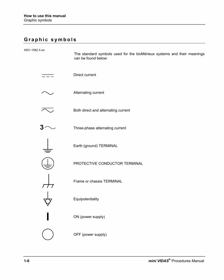
The standard symbols used for the bioMérieux systems and their meanings can be found below:
Direct current
Alternating current
Both direct and alternating current
Three-phase alternating current
Earth (ground) TERMINAL
PROTECTIVE CONDUCTOR TERMINAL
Frame or chassis TERMINAL
Equipotentiality
ON (power supply)
OFF (power supply)

How to use this manual Graphic symbols
1
2
3
4
5
mini VIDAS® Procedures Manual 1-7
"ON" (only for a component of the system equipment)
"OFF" (only for a component of the system equipment)
Equipment protected throughout by DOUBLE INSULATION or REINFORCED INSULATION (equivalent to Class II of IEC 536)
Risk of electric shock
Caution, consult accompanying documents
High temperature
Potential pinch point
Biological risks
Consult Instructions for Use
LOT Batch code
REF or REF Catalogue number
Temperature limitation

How to use this manual Graphic symbols
1-8 mini VIDAS® Procedures Manual
EC REP Authorised Representative in the European Community
Keep dry
Manufacturer
Date of manufacture
IVD In Vitro Diagnostic Medical Device
SN or SN Serial number
Keep away from magnetic field
Separate collection for waste electrical and electronic equipment

mini VIDAS® Procedures Manual 2-1
2 Par ts o f the mini V IDAS
I n t r o d u c t i o n
Each section in the chapter provides a description of the mini VIDAS and mini VIDAS blue components. The following procedures are described in this chapter:
♦ The mini VIDAS hardware ......................................................................... 2-2 ♦ Possibilities of extension.......................................................................... 2-11 ♦ The mini VIDAS software......................................................................... 2-12 ♦ The assay kit............................................................................................ 2-24

Parts of the mini VIDAS The mini VIDAS hardware
2-2 mini VIDAS® Procedures Manual
T h e m i n i V I D A S h a r d w a r e
The mini VIDAS is a completely self-contained unit, intended for use with VIDAS assay kits.
Fig. 2-1: The mini VIDAS blue Fig. 2-2: The mini VIDAS
∗ The hardware contains the following elements: − Space to insert up to 12 single or 6 dual reagent strips. − A fluorometric optical system. − A mechanical system that processes the tests. − An incubation system to maintain all components at required temperatures. − A central processing unit to control the entire mini VIDAS. − A keypad and screen. − A thermal printer. − A strip preparation tray which is used to prepare reagent strips when assays
are already running (only concerns mini VIDAS blue). − A bar code reader to read encoded information from the reagent strip label
and Master Lot Data Cards.
CAUTION! Never use material other than that specified by bioMérieux ® SA.

Parts of the mini VIDAS The mini VIDAS hardware
1
2
3
4
5
mini VIDAS® Procedures Manual 2-3
Sections
The analytical portion of the mini VIDAS contains two compartments called “Sections.” Labeled A and B, the sections operate independently, allowing a variety of tests to be run on the mini VIDAS at the same time.
Reagent str ip tray On the lower portion of each section, a plastic dust cover can be lifted to reveal the reagent strip tray. The tray, shown in the figure below, consists of six channels into which you can slide a reagent strip. Each of the six channels constitutes a position in the section. You can insert up to six single, or three dual reagent strips for a combined capacity of up to 12 tests. The tray is pulled into the instrument during processing.
Fig. 2-3: Reagent strip tray
The strip tray is also used to automatically enter the MLE card.
Note: See chapter 4 "Routine procedures" in this Manual for more information on the MLE Card.
CAUTION! The reagent strip trays are movable parts. Risk of finger pinching.

Parts of the mini VIDAS The mini VIDAS hardware
2-4 mini VIDAS® Procedures Manual
SPR® block
The upper portion of a section has a door that pulls down to reveal the SPR block. The main feature of this compartment is the six-position SPR block, used to hold the SPRs, or Solid Phase Receptacles. The six positions of the block correspond to the six positions in the reagent strip tray. During processing, the SPR block and SPR form a pipetting system that is used in the various steps of the assay process.
Fig. 2-4: SPR block
Operat ing status l ight A small light above the SPR block door indicates the operating status of each section. When the section is running a test, the light is on; when the light is off, the section is idle. A flashing light indicates that the tests in that section are completed, and that the reagent strips and SPRs should be removed.
Microprocessor In addition to the central processing unit, each section of the mini VIDAS contains its own microprocessor. This unit is responsible for storing and operating the assay protocols. A protocol is a series of commands that include the mixing of reagents, washing steps, and optical readings. It allows the mini VIDAS to perform a completely automated assay.
Incubators The assays used in the mini VIDAS require temperature control. Two systems control temperature, one in the reagent strip tray and the other in the SPR block.
Note: For information on temperature monitoring in the mini VIDAS, see Chapter 7.

Parts of the mini VIDAS The mini VIDAS hardware
mini VIDAS® Procedures Manual
Str ip preparat ion tray (only concerns mini VIDAS blue)
A retractable strip preparation tray is located under each reagent stri .
Fig. 2-5: Strip preparation tray closed Fig. 2-6: Opening the strip prepa
Fig. 2-7: Reagent strips placed on the
strip preparation tray Fig. 2-8: Reagent strips placed
strip preparation tray with its
②
p tray
1
2
3
4
5
2-5
ration tray
on the boat
①

Parts of the mini VIDAS The mini VIDAS hardware
2-6 mini VIDAS® Procedures Manual
Detect ion system The mini VIDAS uses a fluorometric scanner as the detection system. The scanner is mounted on a mechanical device that permits it to be used for both sections. The mini VIDAS detects chemical changes in the specialized optical cuvette mounted at the end of every reagent strip. Figure II-9 shows the position of the optical cuvette in a typical reagent strip.
Fig. 2-9: Optical cuvette on a reagent strip
Central processing unit The central processing unit controls all aspects of mini VIDAS operations, including data analysis, and control of the mechanical and optical systems.
Keypad and screen
The keys on the mini VIDAS console are almost completely flat. They are used to enter information which is taken directly into account when the key is pressed. The screen is a liquid crystal type. It conveys all communications from the onboard computer.
Nota: If the intensity of the mini VIDAS blue display decreases considerably or becomes irregular, refer to "Decrease in the intensity of display" on page 6-7. The running of the mini VIDAS blue is in no way affected. Immediately to the right of the screen are five touch keys that are used to select items presented on the screen.
Fig. 2-10: mini VIDAS blue keypad and screen Fig. 2-11: mini VIDAS keypad and screen
Optical cuvette

Parts of the mini VIDAS The mini VIDAS hardware
1
2
3
4
5
mini VIDAS® Procedures Manual 2-7
Ref. Description
1: Display screen This is where all instructions and messages for operating the mini VIDAS are displayed.
2: Option selection keys These five keys are used to select one of up to five options that can appear on the display screen. The options are displayed on the screen opposite the keys (which are black in the manual) used to select them.
3: Numeric keypad
These keys are used to input numbers into the mini VIDAS, and, in some cases, to make input selections. They include the ten digits, 0 - 9, a decimal point, and an <ENTER> key.
4: Function keys
These three keys perform specific functions in the mini VIDAS.
The key represented by a question mark <?> is the help key. • Press this key once to display information for the screen on which you are
working, to view an error after a sound signal has been emitted and/or a flashing screen (see the Configuration Menu).
• Press this key twice for a Help Mode Sceen that provides the following: print screen, mini VIDAS status, information, assay compatibility list. This key is also used to display error messages.
This key is used to return to the previous screen during a procedure It can be used to return to a particular menu or to correct a selection error.
The <UNDO> key is used to undo a keypad input. In some cases it deletes the last input and returns you to the previous operation.
5: Arrow keys These keys are used to move the cursor on certain screens. The <↑>and <↓> keys are also used to page the display screen, that is, to show a second or third page of output that does not fit on one screen.
Internal printer
The mini VIDAS includes an internally mounted thermal printer. The printer is located on the top of the mini VIDAS, directly above the keypad and screen.

Parts of the mini VIDAS The mini VIDAS hardware
2-8 mini VIDAS® Procedures Manual
Rear panel components
The rear panel of the mini VIDAS contains several important hardware components. The location of these components is shown in the figure below.
Fig. 2-12: mini VIDAS rear panel

Parts of the mini VIDAS The mini VIDAS hardware
1
2
3
4
5
mini VIDAS® Procedures Manual 2-9
Ref. Description 1: Memory card slot
This slot is the receptacle for the mini VIDAS software update cards. A memory card is sent to you to perform updates of the mini VIDAS software when required. This recyclable card must be returned to bioMérieux SA or their local representative after your mini VIDAS has been upgraded.
2: Diagnostic port
This cable connection is used to troubleshoot the mini VIDAS and is not part of normal operation. This cable connection can be used if problems occur with the instrument. If necessary, it will be used by a bioMérieux service technician.
3: Computer port
This cable connection can be used to connect the mini VIDAS to a computer. Assay results are then sent to that computer via this connection.
4: Printer port
This cable connection can be used to connect the mini VIDAS to a matrix parallel printer. A parallel / Centronix-type cable and a printer are therefore required.
5: AC power connection
This section of the rear panel contains the hardware for connecting the mini VIDAS to an AC power source. It includes: − ON/OFF switch. − Receptacle for an AC power cord. − Fuse compartment.

Parts of the mini VIDAS The mini VIDAS hardware
2-10 mini VIDAS® Procedures Manual
Bar code readers
There are 2 readers: ∗ A hand-held bar code reader is included in the mini VIDAS configuration. It is
used to: − read the bar codes of certain reagents before they are used. The procedure
for using these reagents is described in "Instructions for use" in the package insert.
− enter the sample ID and read MLE cards.
∗ A bar code reader inside the instrument enables identification of the reagent strips and reading of the MLE card.
Recommendations for use of the bar code reader To read a bar code:
• Hold the reader about 5 cm from the bar code.
• Check that the reader is perpendicular to the bar code (maximum 5° tilt).
• Depress the trigger.
A red beam of light is visible on the bar code.
• Hold the trigger and slowly scan the bar code from top to bottom or bottom to top until the code has been read completely.
A beep and a green LED indicate that reading has been performed correctly.
∗ When reading is complete:
• Release the trigger.
∗ If reading does not occur immediately:
• Slowly move the reader away from and/or towards the bar code until the optimal position for reading has been reached.
• If the problem persists, refer to Chapter 7 "Error handling".

Parts of the mini VIDAS Possibilities of extension
1
2
3
4
5
mini VIDAS® Procedures Manual 2-11
P o s s i b i l i t i e s o f e x t e n s i o n
∗ External printer (optional)
Note: See section "Selecting the printer" on page 3-19 of chapter 3 and appendix D in this manual.
∗ Bar code reader
Note: See section "Reading bar codes" on page 8-42 of this manual.
∗ Unidirectional interface (optional)
Note: See section "LIS user options" on page 3-34 of chapter 3 and appendix E in this manual.

Parts of the mini VIDAS The mini VIDAS software
2-12 mini VIDAS® Procedures Manual
T h e m i n i V I D A S s o f t w a r e The mini VIDAS menus
The mini VIDAS is menu-driven, that is, all of the parts of the software program are selected from a menu, rather than by entering commands. The following figure for example, shows the Main Menu.
Fig. 2-13: mini VIDAS Main Menu

Parts of the mini VIDAS The mini VIDAS software
1
2
3
4
5
mini VIDAS® Procedures Manual 2-13
Selecting a menu option
Five selection keys, located to the right of the screen, enable you to select options in mini VIDAS menus.
∗ Since not all displays use all five selection keys, the boxed selections and lines indicate the active keys. This display uses one of two methods to show the active keys. The figure on page 2-12 illustrates the first method. Notice that each option is in a box with a line extending to a selection key.
∗ The other method of showing active selection keys is used where additional information appears between the option and the selection key. The following figure shows the status screen for the two mini VIDAS sections, A and B.
∗ The sections represent two of the three section options on this screen; the text is status information for each section.
Fig. 2-14: Showing active selection keys
∗ Two things to note on the screen in Figure 2-14 are:
• The active selection keys are noted by the marker “•–” and the enclosed box with a line extending to a selection key
• Only three of the five selection keys are active on this screen

Parts of the mini VIDAS The mini VIDAS software
2-14 mini VIDAS® Procedures Manual
Menu structure
The diagram in Figure 2-15 shows the entire structure of the mini VIDAS menus. Notice that the Main Menu, as the entry point into the mini VIDAS, also serves as the pathway to the other menus in the mini VIDAS. Several of the selections in the VIDAS Main Menu are other menus. This is reflected in the structure diagram below.
Fig. 2-15: mini VIDAS menu structure
When a menu is accessed from another menu, it is called a submenu. Each submenu in the mini VIDAS contains a particular group of programs that are related. The Configuration Menu, for example, contains all the programs that set the configuration of the mini VIDAS. The programs in the mini VIDAS Main Menu are those that you will use most often.

Parts of the mini VIDAS The mini VIDAS software
1
2
3
4
5
mini VIDAS® Procedures Manual 2-15
The status screen The second item in the mini VIDAS Main Menu is labeled “status screen”. This display is used to indicate the current status of the two sections in the mini VIDAS, and to assign assays to them. The status screen is also used to display the temperature of each section’s tray and SPR block. Knowing how to read the status screens is an important part of operating the mini VIDAS.
The f i rst status screen
The first status screen is shown in the figure below.
Fig. 2-16: First status screen
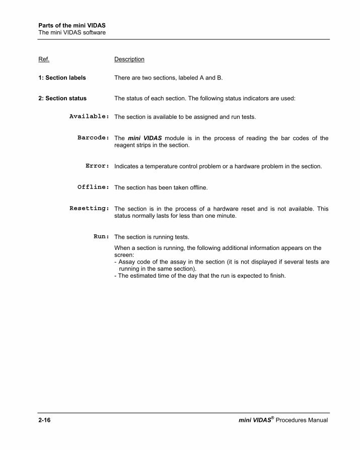
Parts of the mini VIDAS The mini VIDAS software
2-16 mini VIDAS® Procedures Manual
Ref. Description
1: Section labels There are two sections, labeled A and B.
2: Section status The status of each section. The following status indicators are used:
Available: The section is available to be assigned and run tests.
Barcode: The mini VIDAS module is in the process of reading the bar codes of the
reagent strips in the section.
Error: Indicates a temperature control problem or a hardware problem in the section.
Offline: The section has been taken offline.
Resetting: The section is in the process of a hardware reset and is not available. This
status normally lasts for less than one minute.
Run: The section is running tests.
When a section is running, the following additional information appears on the screen: - Assay code of the assay in the section (it is not displayed if several tests are
running in the same section). - The estimated time of the day that the run is expected to finish.

Parts of the mini VIDAS The mini VIDAS software
1
2
3
4
5
mini VIDAS® Procedures Manual 2-17
Start error: There is an error related to the preprocessing of a reagent strip.
Press the <?> key to display the status of each position in the section. Possible start errors are: − Bad bar code: the mini VIDAS was unable to read the bar code on the
reagent strip. It must be entered manually. − Bad substrate: the initial fluorescence reading of the substrate is not
acceptable. The reagent strip must be replaced. − Incompatible: the assay in this position is not compatible with other assays in
the section. (the assay cannot be run at the same time as the others in the same section). The assay must be removed from the section and rerun with other tests with which it is compatible.
− Misaligned: a dual reagent strip has been placed in the wrong positions. Dual reagent strips must be placed in positions 1 & 2, 3 & 4, or 5 & 6.
− No strip: a reagent strip was specified for this position but none was found. − Unknown assay: there is no protocol stored in the mini VIDAS for the assay
type. − Wrong type: the type of assay specified for this position differs from the one
found. − No MLE card: the MLE card was not read for the assay. − The reagent lot used has expired. − Expired calibration: the validity date of the last calibration for this assay or lot
has expired. − Unknown calibration: there is no calibration in the mini VIDAS for this assay
or lot and there are no calibrators in the job list.
Starting: The section has completed the preprocessing steps and is preparing to run tests.
Unload: The section is waiting for the SPR to be removed. This occurs at the completion of a run, and is accompanied by the blinking of the operating status light located over the SPR block door.
3 : The "•–" marker Indicates that a selection key is active and that a section can be selected.
4: Display temperature If you select this key, a screen is displayed showing the internal temperature of
each reagent strip tray and SPR block.

Parts of the mini VIDAS The mini VIDAS software
2-18 mini VIDAS® Procedures Manual
The second status screen
The second status screen is accessed by selecting one of the two sections on the first screen. The purpose of the second status screen is to display the tests you have assigned to each position within the section. The following figure shows a second status screen after all six positions have been assigned.
Fig. 2-17: Second status screen
Ref. Description
1: Screen label This label shows you are looking at the status of section B.
2: Position numbers These numbers identify the six positions in the section.
3: Assay code These codes appear as tests are assigned to the section or after the strip's bar code has been read.
4: Standards, control If a position is assigned to a standard or control, this type of designator appears.
5: Start A selection option to start processing. In other circumstances, this selection may have another function.
halt: This function appears while the section is processing. Use it to halt the processing.
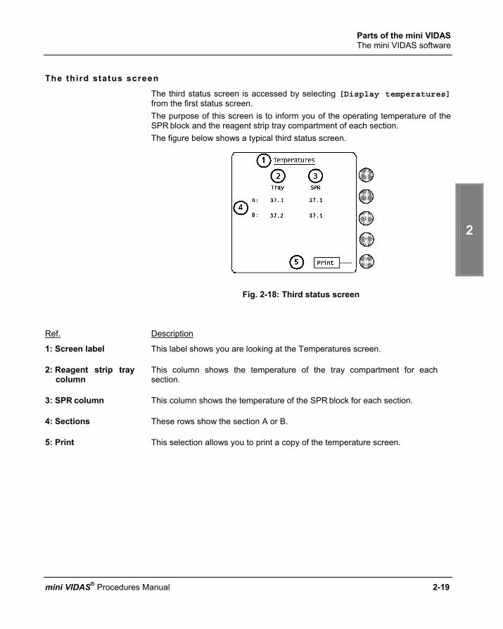
Parts of the mini VIDAS The mini VIDAS software
1
2
3
4
5
mini VIDAS® Procedures Manual 2-19
The third status screen
The third status screen is accessed by selecting [Display temperatures] from the first status screen. The purpose of this screen is to inform you of the operating temperature of the SPR block and the reagent strip tray compartment of each section. The figure below shows a typical third status screen.
Fig. 2-18: Third status screen
Ref. Description
1: Screen label This label shows you are looking at the Temperatures screen.
2: Reagent strip tray column
This column shows the temperature of the tray compartment for each section.
3: SPR column This column shows the temperature of the SPR block for each section.
4: Sections These rows show the section A or B.
5: Print This selection allows you to print a copy of the temperature screen.

Parts of the mini VIDAS The mini VIDAS software
2-20 mini VIDAS® Procedures Manual
Online help
You can display information on the menu or program you are using by accessing the online help function. Pressing the <?> key on the keypad activates this function. If you press the <?> key a second time, the following screen appears:
Fig. 2-19: Help mode screen
The help mode screen provides the following functions:
Print Screen:
Creates a printout of the screen from which you accessed the help function.
Information: Displays the first help screen.
System Status: Displays the current date/time and the instrument status.
Assay compatibility
list:
Displays a list of the mini VIDAS assay codes classified according to compatibility. Compatible assays are assays with the same protocol = assays which can be run simultaneously in the same section.

Parts of the mini VIDAS The mini VIDAS software
1
2
3
4
5
mini VIDAS® Procedures Manual 2-21
Viewing error messages
The <?> key also functions to display error messages. Should something happen on your mini VIDAS that requires your attention, the mini VIDAS will start to beep. When you press the <?> key in this mode, the screen displays an error message. The following figure is one example of the type of display you see:
Screen paging
Using the arrow keys Some of the displays in the mini VIDAS are too long for one screen. In these cases you can page the screen display using the <↑> and <↓> arrow keys. The following figure, showing the Configuration Menu, illustrates this function:
• Note the arrow on the screen.
∗ To display additional items, • Press the <↓> arrow key.
∗ After the <↓> arrow key is pressed, another arrow appears at the top of the display, indicating that you can use the <↑> arrow key to page the display back.

Parts of the mini VIDAS The mini VIDAS software
2-22 mini VIDAS® Procedures Manual
Paging bar
Some mini VIDAS screens have what is called a paging bar, as illustrated in the following figure:
A paging bar is generally used for displays that require several screens.
As you page down to the last page, the solid bar moves down the slot.
Its position is relative to your position within the possible pages.
The next page of this display would be similar to the following figure:

Parts of the mini VIDAS The mini VIDAS software
1
2
3
4
5
mini VIDAS® Procedures Manual 2-23
Memory cards
A memory card is a storage device for software, similar to the more familiar floppy disks. The mini VIDAS uses this type of device because of its small size and convenience. Should the software for your mini VIDAS be updated, bioMérieux SA will send you a program update memory card. This card remains the property of bioMérieux SA. It should be returned to bioMérieux SA after your instrument has been upgraded. A special program takes the software from this card and places it in the mini VIDAS's internal memory for permanent storage.
IMPORTANT! Memory cards: - must be protected from humidity, extreme temperatures, direct sunlight, and strong magnetic fields. - must not be subjected to flexing, - must not be subjected to severe impacts.

Parts of the mini VIDAS The assay kit
2-24 mini VIDAS® Procedures Manual
T h e a s s a y k i t
Each mini VIDAS assay kit provides the materials required to run a specific assay. The materials vary for each assay, but generally a kit contains: − single or dual reagent strips, − SPRs (Solid Phase Receptacle):
. one per single reagent strip,
. two per dual reagent strip − control(s) − the necessary standard(s) − a diluent, if required, − a package insert, − an MLE card.
Single reagent str ip The mini VIDAS single reagent strip has ten wells. The sample is placed in the sample well. The other eight wells contain the necessary reagents (conjugate, solvent, wash buffer). The last well is the optical cuvette in which the fluorescence of the substrate is measured. A small tab ensures that the strip is correctly positioned in its channel guides.
Fig. 2-20: Single reagent strip
Tab

Parts of the mini VIDAS The assay kit
1
2
3
4
5
mini VIDAS® Procedures Manual 2-25
Dual reagent str ip
Some assays use a dual reagent strip, two strips attached side by side. The sample is equally divided between the two sample wells of the dual reagent strip. With the strip oriented as shown in figure 2-21, the strip on the top is the sample reference strip. The one on the bottom is the sample test strip. The dual reagent strip configuration is used to compensate for sample variability. The sample test strip contains a reagent that is not included in the sample reference strip. Measurements taken from both strips are used to determine the test result. Dual strips fit in the reagent strip tray exactly like single strips, but they require two channels.
Fig. 2-21: Dual reagent strip
The label
Each mini VIDAS reagent strip has a label, a colored dot and the assay code (2 or 4 letters/digits). The color-coded dot corresponds to a matching dot on the test's companion SPR. The bar code identifies: − the assay name, − the manufacturing batch code, − the sequence number, − the expiration date of the test kit for the mini VIDAS. The figure below represents a typical label:
② ③ ⑤ ⑥ ⑦
④ ①
Fig. 2-22: Reagent strip label
Parts of the mini VIDAS The assay kit
2-26 mini VIDAS® Procedures Manual
Ref. Description
1: Bar codes Under normal operating conditions, the internal bar code reader reads the machine readable code.
2: Alphanumeric representation of the bar code If the system is unable to read this code, the alphanumeric form of the bar code is used to enter the bar code.
3: Assay name The assay code is based on two or four characters and/or figures which represent the name of the assay to be performed;
Examples: RBG RUB IgG (Immunoassay)
153 CA 15-3
All references to an assay in the software and on printed reports use the assay code.
4: ID A blank space is provided to write the sample ID (if required).
5: Batch code The Batch code is used by the mini VIDAS to code the expiration date of the reagent lot.
6: Expiration date This corresponds to the expiration date of the reagent lot. When the bar code reader reads this date, the mini VIDAS compares it to the date stored in its memory to ensure that the lot has not passed its expiration date.
7: Sequence Number Within a single batch, each reagent tray carries a different number corresponding to the order of manufacture.

Parts of the mini VIDAS The assay kit
1
2
3
4
5
mini VIDAS® Procedures Manual 2-27
The SPR
The Solid Phase Receptacle, or SPR (pronounced “spur”), is a specially designed plastic pipette-shaped device. During manufacturing, the interior of the SPR is coated with antibody, antigen, or other treatments that capture a target analyte. Each SPR has a corresponding mini VIDAS reagent strip included in the test kit; both are coded with matching color dots and assay code. It is critical that SPRs be paired only with strips that have matching dots, otherwise the test result will be invalid. The figure below shows a typical SPR.
Fig. 2-23: Solid phase receptacle (SPR)

Parts of the mini VIDAS The assay kit
2-28 mini VIDAS® Procedures Manual
How the SPR functions
The SPR block is part of an automated pipetting system that uses the SPRs to mix and transfer reagents during processing. The mini VIDAS uses the SPR to withdraw or dispense liquid from or to a well in the reagent strip. The beveled tip of the SPR enables it to pierce the protective seal that covers the wells in a reagent strip. The reagent strip tray then moves in and out to allow liquids to be transferred from one well to another. The mini VIDAS uses the SPR to accomplish all the required processing steps, including: − sampling, − incubation, − mixing, − washing. The sample is drawn into and out of the SPR. The target analyte from the sample binds to the SPR's interior coating (antibody, antigen, etc.). Various washes remove unbound and interfering substances. The target analyte is labeled by an enzyme-conjugated antibody or antigen, forming a "sandwich". The immobilized enzyme catalyzes the breakdown of the substrate into a fluorescent end product. The optical scanner obtains fluorescence readings of the substrate material and transmits the measurement to the central processing unit for analysis.

mini VIDAS® Procedures Manual 3-1
3 Get t ing s tar ted
I n t r o d u c t i o n
This chapter covers the very first steps you need to take before you can use the mini VIDAS. The following procedures are described in this chapter:
♦ Aim / Description........................................................................................ 3-2 ♦ Precautions for installation and use ........................................................... 3-3 ♦ Unpacking the mini VIDAS......................................................................... 3-5 ♦ Starting the mini VIDAS ............................................................................. 3-7 ♦ Shutting down the mini VIDAS ................................................................. 3-10 ♦ Configuring the mini VIDAS ..................................................................... 3-11 ♦ Installing paper in the printer.................................................................... 3-38 ♦ Print screen.............................................................................................. 3-40

Getting started Aim / Description
3-2 mini VIDAS® Procedures Manual
A i m / D e s c r i p t i o n
mini VIDAS is a compact, multiparametric, automated immunoanalyzer.
∗ Automated immunoanalyzer After the samples have been dispensed by the user, the mini VIDAS automatically performs the different stages of analysis, including the printing of reports. The software processes the reagents using their bar codes and can send the mini VIDAS results to a Laboratory Information System (uni-directional interface). The bar code labels on the sample tubes can be read using an independent bar code reader (optional). The mini VIDAS has a built-in system for detecting and reporting errors. Its unique design enables it to operate around the clock and daily start-up is completed in a few seconds.
∗ Compact The mini VIDAS is a completely self-contained unit that includes: − an analytical module,
(12 test positions i.e. two 6-test sections) and, − data processing equipment (monitor, keypad, printer).
∗ Multiparametric The mini VIDAS enables 10 different analytes to be used simultaneously and up to 30 results can be produced per hour.
∗ Immunoassays The mini VIDAS is used with VIDAS assay kits covering numerous immunoassay * fields: − hepatitis, − AIDS, − serology testing, − bacterial and viral antigen detection, − fertility/pregnancy monitoring, − thyroid hormones, − allergies, − tumor markers, − endocrinology, − anemia, − cardiovascular diseases, − therapeutic drug monitoring, − immuno-hemostasis, − industrial microbiology.
* The availability of certain VIDAS tests may be restricted in some countries, depending on registration release dates.
Contact your local sales representative for details.

Getting started Precautions for installation and use
1
2
3
4
5
mini VIDAS® Procedures Manual 3-3
P r e c a u t i o n s f o r i n s t a l l a t i o n a n d u s e
CAUTION! Before unpacking the instruments, it is advisable to have previously planned where they will be placed. The mini VIDAS blue should be lifted or moved using the gripping area located on its base. Avoid exposing the equipment to direct sunlight, excessive heat, humidity or dust. To ensure that the temperature control maintains the temperature at 37°C, the system must be set up in a room with an ambient temperature of between 15°C and 30°C. Leave sufficient clearance around the analytical module for the circulation of air, essential to proper temperature control, and for easy access to the power switch. Only power cords and accessories supplied by bioMérieux® sa should be used to connect the instruments. Nothing should be placed on top of the connection cables, whether temporarily, permanently or intermittently. Cables should not be laid across passage-ways. Computer cables must not intersect or be placed too close to cables for connection of the power supply. Cables should not be allowed to form loops or knots, or be rolled up near or on other electrical equipment. All connections should be performed with the power OFF. Before connecting the system to the power supply, check that all switches are in the OFF position. The electrical supply to which the system is connected must conform to current standards: - diameter of cables, - grounding, - protection through circuit breaker and/or use of fuse, - connector calibration and type etc.
Getting started Precautions for installation and use
3-4 mini VIDAS® Procedures Manual
The electrical power supply must be: - direct, - individual, - calibrated, - protected, - compatible with the technical specifications of the product or configuration. No other equipment likely to interfere with the proper functioning of the system should be connected on the same circuit. Extension sockets and serially connected adapters should not be used. If the power supply is not sufficient to guarantee proper functioning of the product, an independent protective device, adapted to the product's technical characteristics should be used. Do not use power sockets controlled by wall-mounted switches or timers. Accidental power cuts may destroy information in both the analytical module and the computer memories. No electrical equipment likely to cause interference (equipment not bearing the CE mark …) should be operated in the immediate vicinity of the system. The safety connection should not be interrupted by an extension cord without a protection conductor. Before connecting or disconnecting the connecting cables, check that the power supply cords of the CPU and all the units connected to it are themselves disconnected. When adding units to the system or removing them, disconnect the power cables to these units before connecting or disconnecting the connecting cables. Never connect the mini VIDAS to the same power supply as devices which generate high current surges (centrifuges) or which, due to frequent start-ups, generate interferences if they are ill-protected (freezers, water baths etc.).

Getting started Unpacking the mini VIDAS
1
2
3
4
5
mini VIDAS® Procedures Manual 3-5
U n p a c k i n g t h e m i n i V I D A S
Preparat ions before unpacking
CAUTION! Any damage directly or indirectly resulting from the transport of the instrument without adequate containers will not be covered by the warranty or maintenance contract.
∗ Make sure that all the items in the packing list have been delivered.
∗ Make sure that no damage has been caused during transportation.
∗ The instrument must be placed on a flat surface with a maximum horizontality defect of 5°.
Note: See Appendix A for a complete listing of mini VIDAS specifications.
Step 1 • Place the box containing the mini VIDAS on the floor and open the top of the shipping box.
Note: Retain the shipping box and packing materials in case you need to ship the mini VIDAS at a later date.
Step 2 • Remove the instrument from the shipping box and place it on the floor.
CAUTION! The mini VIDAS blue weighs 40 kg (88 lb). The mini VIDAS weighs 37 kg (81.5 lb). Two people should lift it out of its box and place it on the benchtop.
CAUTION! The mini VIDAS blue should be lifted or moved using the gripping area
located on its base.

Getting started Unpacking the mini VIDAS
3-6 mini VIDAS® Procedures Manual
Step 3 • Remove the foam end caps and the antistatic bag. (see Note in Step 1 above).
Step 4 • Place the instrument on the benchtop.
Step 5 • Remove the tape securing the dust covers. (See the figure below).
Fig. 3-1: mini VIDAS dust covers
Step 6 • Open each dust cover. • Remove the shipping block (See Note in Step 1 above).
Note: The shipping block in Section A (on the left as you face the instrument) has a rod attached to it. This rod secures the optical scan head during shipment and must be removed with the shipping block.
Dust covers

Getting started Starting the mini VIDAS
1
2
3
4
5
mini VIDAS® Procedures Manual 3-7
S t a r t i n g t h e m i n i V I D A S
DANGER! Any break in the grounding protective conductor inside or outside the equipment or disconnection of the protective ground terminal may render the equipment dangerous. Deliberate interruption of such conductors is forbidden. After opening, if it is imperative to switch the instrument on, any adjustment, servicing or repair should be performed by a qualified technician, well aware of the possible risks. During a storm, never connect cables to the keyboards, screens, printer or telephones, or lightning conductors to the transmission lines.
Note: All software required for the mini VIDAS has been loaded into the mini VIDAS. Follow these steps to start your mini VIDAS.
Step 1 • Connect the power cord to the mini VIDAS and an appropriate power outlet. Note: See Appendix A for mini VIDAS power specifications.
Step 2 • Reach behind the instrument and turn the power on (see figure below).
Fig. 3-2: Power switch
CAUTION! The power switch is located on the back of the analytical module. It must be easy to reach at all times.
ON/OFF switch and power outlet

Getting started Starting the mini VIDAS
3-8 mini VIDAS® Procedures Manual
• Allow the mini VIDAS to warm up for 45 minutes. During initialization, the optical system automatically calibrates against a standard which reacts to temperature.
• Put the "ON/OFF" switch on the analytical module in the "OFF" position.
• Wait 1 minute and put the switch back in the "ON" position. This operation enables the standard value to be memorized after the temperature has stabilized.
This procedure involves the following:
− Software self test and diagnostics. This part of the sequence is not noticeable.
− Hardware self test. The mini VIDAS tests all its motors. Expect to hear noises inside the instrument and to see the reagent strip trays (under the dust covers) retract into the instrument.
− Software boot sequence. The boot sequence is a program that loads the mini VIDAS software into its memory.
∗ During this sequence, expect to see the following messages on the display screen:
Booting Initializing... Please Wait
The mini VIDAS may be left on 24 hours a day for three reasons: − to avoid problems when it is turned on, − to avoid incorrect auto-calibration, − to enable the temperature of electrical components to remain stable
The mini VIDAS can therefore be used at any time during the day.
Note: If the room temperature is too low when the mini VIDAS is turned on, error 160 will be generated after the initialization phase or when the instrument is restarted. After complete reinitialization, turn off the mini VIDAS and then turn it back on again. If error 160 persists, call bioMérieux Technical Assistance.
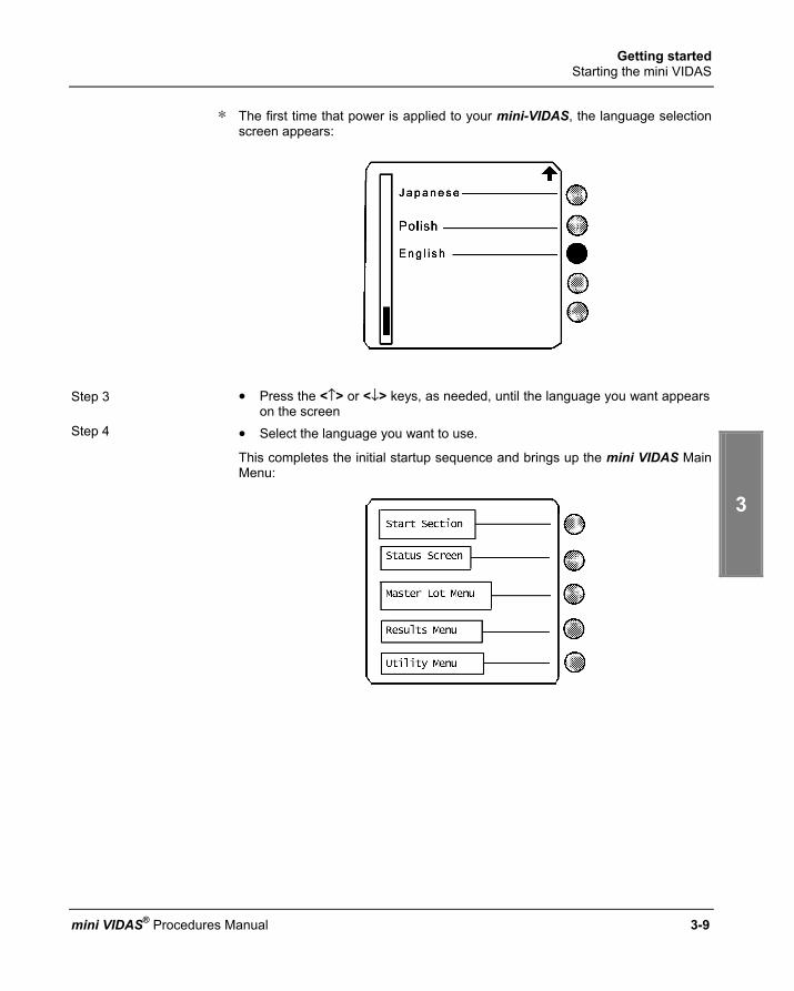
Getting started Starting the mini VIDAS
1
2
3
4
5
mini VIDAS® Procedures Manual 3-9
∗ The first time that power is applied to your mini-VIDAS, the language selection screen appears:
Step 3 • Press the <↑> or <↓> keys, as needed, until the language you want appears on the screen
Step 4 • Select the language you want to use.
This completes the initial startup sequence and brings up the mini VIDAS Main Menu:

Getting started Shutting down the mini VIDAS
3-10 mini VIDAS® Procedures Manual
S h u t t i n g d o w n t h e m i n i V I D A S
∗ If the mini VIDAS has been shut down for an extended period of time, wait for 45 minutes after switching it on again, then turn it off and on once more so that it can autocalibrate at 37°C.
Note: The "park system" procedure should only be performed when the mini VIDAS has to be transported (see page 6-25).
∗ When the mini VIDAS is shut down the following are stored in memory: − the software, − the protocols, − the configuration, − the results of the last two calibrations per assay, − Master Lot Data.
∗ The following are erased: − assay results (except calibration results), − error messages.

Getting started Configuring the mini VIDAS
1
2
3
4
5
mini VIDAS® Procedures Manual 3-11
C o n f i g u r i n g t h e m i n i V I D A S CAUTION! Configuration parameters should only be modified by trained and qualified
personnel. Any modification to configuration parameters may lead to problems when the system is used or cause it to operate in an unexpected manner. Make sure that modifications are necessary and justified. The procedures in this section are accessed from the Configuration Menu. Proceed as follows to reach the Configuration Menu:
Main Menu
Utility Menu
Configuration Menu
Fig. 3-3: Accessing the Configuration Menu
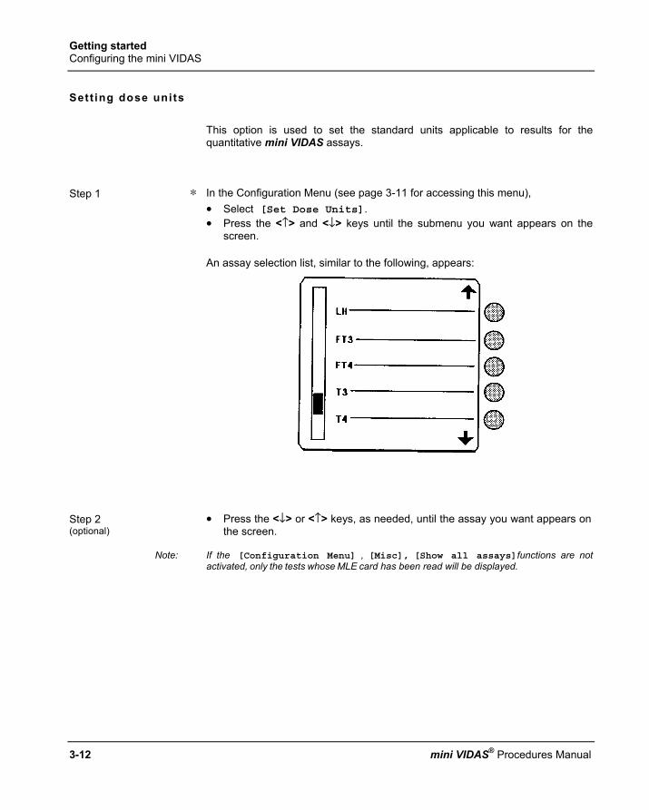
Getting started Configuring the mini VIDAS
3-12 mini VIDAS® Procedures Manual
Sett ing dose uni ts
This option is used to set the standard units applicable to results for the quantitative mini VIDAS assays.
Step 1 ∗ In the Configuration Menu (see page 3-11 for accessing this menu), • Select [Set Dose Units]. • Press the <↑> and <↓> keys until the submenu you want appears on the
screen.
An assay selection list, similar to the following, appears:
Step 2 (optional)
• Press the <↓> or <↑> keys, as needed, until the assay you want appears on the screen.
Note: If the [Configuration Menu] , [Misc], [Show all assays]functions are not activated, only the tests whose MLE card has been read will be displayed.
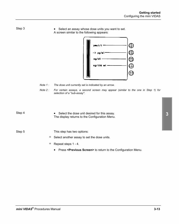
Getting started Configuring the mini VIDAS
1
2
3
4
5
mini VIDAS® Procedures Manual 3-13
Step 3 • Select an assay whose dose units you want to set.
A screen similar to the following appears:
Note 1 : The dose unit currently set is indicated by an arrow.
Note 2 : For certain assays, a second screen may appear (similar to the one in Step 1) for selection of a "sub-assay".
Step 4 • Select the dose unit desired for this assay.
The display returns to the Configuration Menu. Step 5 This step has two options:
∗ Select another assay to set the dose units.
∗ Repeat steps 1 - 4.
• Press <Previous Screen> to return to the Configuration Menu.
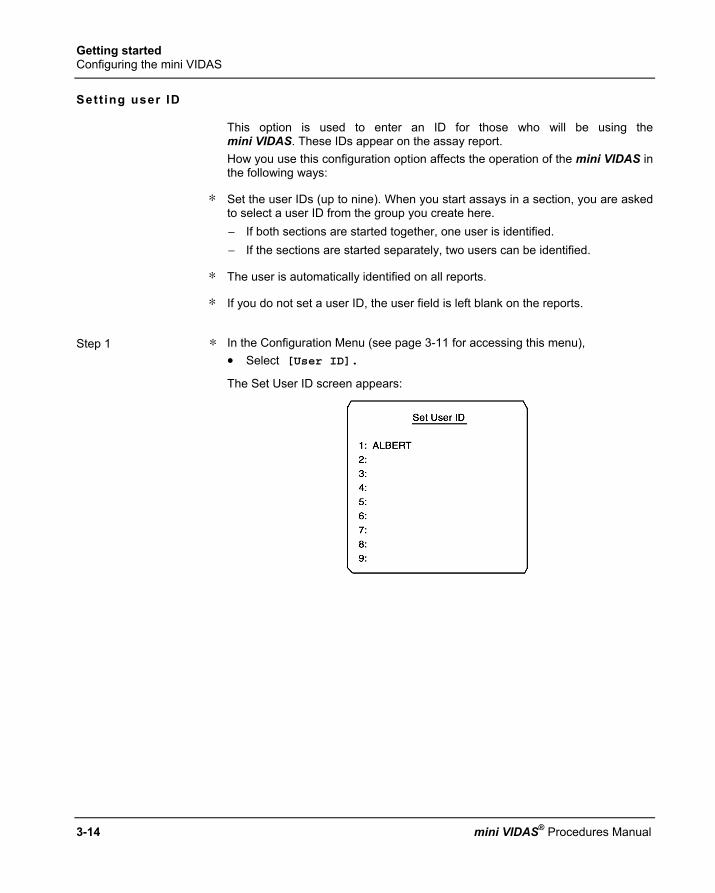
Getting started Configuring the mini VIDAS
3-14 mini VIDAS® Procedures Manual
Sett ing user ID
This option is used to enter an ID for those who will be using the mini VIDAS. These IDs appear on the assay report. How you use this configuration option affects the operation of the mini VIDAS in the following ways:
∗ Set the user IDs (up to nine). When you start assays in a section, you are asked to select a user ID from the group you create here. − If both sections are started together, one user is identified. − If the sections are started separately, two users can be identified.
∗ The user is automatically identified on all reports.
∗ If you do not set a user ID, the user field is left blank on the reports.
Step 1 ∗ In the Configuration Menu (see page 3-11 for accessing this menu), • Select [User ID].
The Set User ID screen appears:

Getting started Configuring the mini VIDAS
1
2
3
4
5
mini VIDAS® Procedures Manual 3-15
Step 2 • Press a digit, 1 - 9, on the <Number Key> pad, corresponding to the first
through the ninth user entered. The User ID screen appears:
The space next to the "Z" character can be used to create a space in your ID.
Step 3 • Press the <↑>, <↓>, <←> and <→> keys to highlight the appropriate
character in the character box. Step 4 • Validate this character by pressing the selection key.
The character appears in the cursor box. Step 5 • Repeat steps 3 and 4 to create an ID of up to 10 characters.
• Use these functions as required:
[Clr] to clear the cursor box. [←] to delete one character in front of the cursor.
Step 6 • Press <Previous Screen> to return to the Set User ID screen. Step 7 This step has two options:
∗ To enter another user, • Repeat steps 2 - 6.
∗ To return to the Configuration Menu, • Press the <Previous Screen> key.

Getting started Configuring the mini VIDAS
3-16 mini VIDAS® Procedures Manual
Sett ing the report header This option is used to define a line of up to 32 characters. This line appears in the header information of the assay report.
Step 1 ∗ In the Configuration Menu (see page 3-11 for accessing this menu), • Select [Report Header]. • Press the <↑> and <↓> keys until the submenu you want appears on the
screen. The Header screen appears:
The space next to the "Z" character can be used to create a space in your header.
Step 2 • Press the <↑>, <↓>, <←> and <→> keys to highlight the appropriate
character in the character box. Step 3 • Validate this character by pressing the selection key.
The character appears in the cursor box. Step 4 • Repeat steps 2 and 3 to create a report header of up to 32 characters.
• Use these functions as required:
[Clr] to clear the cursor box. [←] to delete one character in front of the cursor.
Note: The display shows a maximum of 14 characters. If the report header created is longer, the symbol "<" will appear first followed by the last 14 characters.
Step 5 ∗ To return to the Configuration Menu,
• Press the <Previous Screen> key.

Getting started Configuring the mini VIDAS
1
2
3
4
5
mini VIDAS® Procedures Manual 3-17
Sett ing the date and t ime This option is used to set the date and time for the mini VIDAS. These values appear on the assay report and all other places in the software where the date or time of day is used.
CAUTION! Incorrect setting of the date and time can lead to incorrect running of programs and loss of data.
Step 1 ∗ In the Configuration Menu (see page 3-11 for accessing this menu), • Select [Set Date/Time].
The following screen appears:
Step 2 • Set the date and time using the following functions:
[Clr] to clear the cursor box. [←] to delete one character in front of the cursor. <Number Keypad> pad to fill in the numerical value for a day, month, year, hour or minute.
Note: Use the <ENTER> key to validate the numerical values. Step 3 ∗ To return to the Configuration Menu,
• Press the <Previous Screen> key.

Getting started Configuring the mini VIDAS
3-18 mini VIDAS® Procedures Manual
Sett ing display contrast The liquid crystal display on the mini VIDAS has a contrast adjustment to allow for proper viewing in different room lighting conditions. Use this procedure to adjust the contrast.
CAUTION! Too much contrast could reduce the life span of your monitor. It is recommended that you use your mini VIDAS for several days with the original setting before modifying the contrast.
Step 1 ∗ In the Configuration Menu (see page 3-11 for accessing this menu),
• Select [Set Display Contrast]. Step 2 The following screen appears:
Step 3 ∗ To adjust the contrast,
• Press the <↑> or <↓> key. The contrast bar and relative contrast level (number in the box) go up or down in response to your adjustments. The actual display contrast also changes as you make the adjustments.
Step 4 ∗ (optional)
To go back to the default setting, • Press the <UNDO> key.
Step 5 ∗ To return to the Configuration Menu,
• Press the <Previous Screen> key.

Getting started Configuring the mini VIDAS
1
2
3
4
5
mini VIDAS® Procedures Manual 3-19
Select ing the printer
∗ With this option you can select the internal thermal printer, or an external matrix parallel printer.
Step 1 ∗ In the Configuration Menu, • Select [Select Printer]. • Press the <↑> and <↓> keys until the submenu you want appears on the
screen.
Step 2 The following selections appear:
[Internal Printer]
[External Printer]
Note: A ⌧ symbol indicates the current setting.
Step 3 • Select the printer you want to use.
IMPORTANT! Before selecting an external printer, see Appendix D for external printer installation instructions.
Step 4 ∗ To return to the Configuration Menu, • Press the <Previous Screen> key.

Getting started Configuring the mini VIDAS
3-20 mini VIDAS® Procedures Manual
Sett ing the date/ t ime format
∗ To set the format of the date and time used on the reports,
• Use this option. Step 1 ∗ In the Configuration Menu,
• Select [Set Date/Time Format]. • Press the <↑> and <↓> keys until the submenu you want appears on the
screen.
Step 2 The Date/Time format screen appears:
Note: If you do not want to change the current time separator,
• Go to Step 5.

Getting started Configuring the mini VIDAS
1
2
3
4
5
mini VIDAS® Procedures Manual 3-21
Step 3 • Select [Time Separator] on the Date/Time Format screen
The following selections appear: [:] (colon) [.] (period) [,] (comma)
Step 4 • Select a time separator.
The display automatically returns to the Date/Time format screen.
Note: If you do not want to change the current date separator, • Go to Step 7.
Step 5 • Select [Date Separator] on the Date/Time format screen.
The following selections appear: [/] (slash) [-] (dash) [.] (period)
Step 6 • Select a date separator.
The display automatically returns to the Date/Time format screen.
Note: If you do not want to change the current date/time format, • Go to Step 9.

Getting started Configuring the mini VIDAS
3-22 mini VIDAS® Procedures Manual
Step 7 • Select [Format] on the Date/Time format screen.
The following selections appear: [HH.MM ddmmm]
[HH.MM ddmmmyy]
[HH.MM yy.mm.dd]
[HH.MM.SS ddmmmyy]
[HH.MM mm.dd.yy]
∗ To display the selection [HH.MM dd.mm.yy],
• Press the <↓> key.
Note: The date and time separators used in this display are those that you selected in Step 5 above.
Step 8 • Select a date/time format.
The display automatically returns to the Date/Time format screen. Step 9 ∗ To return to the Configuration Menu,
• Press the <Previous Screen> key.

Getting started Configuring the mini VIDAS
1
2
3
4
5
mini VIDAS® Procedures Manual 3-23
Defining the sample ID character sets This option enables you to define two separate three-character ID sets. Use one or both of these sets to input repetitive characters for sample IDs.
Step 1 ∗ In the Configuration Menu, • Select [Define Sample ID Character Sets]. • Press the <↑> and <↓> keys until the submenu you want appears on the
screen.
Step 2 The following selections appear:
[Sample ID Set 1]
[Sample ID Set 2]
Step 3 • Select one of the two character sets to define. The following screen appears:
The space next to the "Z" character can be used to create a space in your ID set.

Getting started Configuring the mini VIDAS
3-24 mini VIDAS® Procedures Manual
Step 4 ∗ To highlight the appropriate character in the character box,
• Press the <↑>, <↓>, <←> and <→> keys. Step 5 • Validate this character by pressing the selection key.
It then appears in the cursor box. Step 6 • Repeat Steps 4 and 5 to add up to three additional characters to the ID.
Use these functions as needed: [Clr] to clear the cursor box. [←] to delete one character in front of the cursor.
Step 7 This step has two options:
∗ If you have finished defining sample ID character sets,
• Press the <Previous Screen> key two times to exit to the Configuration Menu.
∗ If you want do define the other ID character set,
• Press the <Previous Screen> key once and return to Step 3.

Getting started Configuring the mini VIDAS
1
2
3
4
5
mini VIDAS® Procedures Manual 3-25
Changing the keycl ick volume
When you press any key on the keypad, there is an audible tone that confirms the keystroke. Use this procedure to change the volume of that tone.
Step 1 ∗ In the configuration Menu,
• Select [Sound Menu]. • Press the <↑> and <↓> keys until the submenu you want appears on the
screen. Step 2 • Select [Keyclick Volume] in the Sound Menu.
The following screen appears:
Step 3 ∗ To adjust the keyclick volume,
• Press the <↑> and <↓> keys. The volume bar and relative volume level (number in the box) go up or down in response to your adjustments.
Step 4 ∗ (optional)
To go back to the default setting, • Press the <UNDO> key.
Step 5 ∗ To return to the Sound Menu, • Press the <Previous Screen> key.

Getting started Configuring the mini VIDAS
3-26 mini VIDAS® Procedures Manual
Changing the beep volume
The beep is the tone you hear when you press a key that is inactive (it should not be pressed on the particular screen you are viewing). Use this procedure to change the volume of that tone.
Step 1 ∗ In the Configuration Menu, • Select [Sound Menu]. • Press the <↑> and <↓> keys until the submenu you want appears on the
screen. Step 2 • Select [Beep Volume].
The following screen appears:
Step 3 ∗ To adjust the beep volume,
• Press the <↑> and <↓> keys. The volume bar and relative volume level (number in the box) go up or down in response to your adjustments.
Step 4 ∗ (optional)
To go back to the default setting, • Press the <UNDO> key.
Step 5 ∗ (optional)
To hear the tone at the adjusted volume, • Select [Test].
Step 6 ∗ To return to the Sound Menu,
• Press the <Previous Screen> key.

Getting started Configuring the mini VIDAS
1
2
3
4
5
mini VIDAS® Procedures Manual 3-27
Error beeps
∗ When an error occurs, the mini VIDAS begins to beep. The beep grows louder over a 5 minute period. You can set the initial and final volume of this error beep.
Sett ing ini t ia l error volume
Step 1 ∗ In the Configuration Menu, • Select [Sound Menu]. • Press the <↑> and <↓> keys until the submenu you want appears on the
screen. Step 2 • Select [Initial Error Volume] in the Sound Menu.
The following screen appears:
Step 3 ∗ To adjust the initial error beep volume,
• Press the <↑> and <↓> keys. The volume bar and relative volume level (number in the box) go up or down in response to your adjustments.
Step 4 ∗ (optional)
To go back to the default setting, • Press the <UNDO> key.
Step 5 ∗ (optional)
To hear the tone at the adjusted volume, • Select [Test].
Step 6 ∗ To return to the Sound Menu,
• Press the <Previous Screen> key.

Getting started Configuring the mini VIDAS
3-28 mini VIDAS® Procedures Manual
Sett ing the f inal error volume
Step 1 ∗ In the Configuration Menu,
• Select [Sound Menu]. • Press the <↑> and <↓> keys until the submenu you want appears on the
screen. Step 2 • Select [Final Error Volume] in the Sound Menu.
The following screen appears:
Step 3 ∗ To modify the final error beep volume.
• Press the <↑> and <↓> keys. The volume bar and relative volume level (number in the box) go up or down in response to your adjustments.
Step 4 ∗ (optional)
To hear the tone at the adjusted volume, • Select [Test].
Step 5 ∗ (optional)
To go back to the default setting, • Press the <UNDO> key.
Step 6 ∗ To return to the Sound Menu,
• Press the <Previous Screen> key.

Getting started Configuring the mini VIDAS
1
2
3
4
5
mini VIDAS® Procedures Manual 3-29
Enabling display bl inking
While not a sound function per se, display blinking is associated with the error beep since it only occurs during an error condition. Use this procedure to enable or disable the display blinking function. When enabled, it causes the display to blink (flash on and off) when an error occurs.
Step 1 ∗ In the Configuration Menu,
• Select [Sound Menu]. • Press the <↑> and <↓> keys until the submenu you want appears on the
screen. Step 2 ∗ To select [Display Blinking] in the Sound Menu,
• Press the <↓> key once. The following selections appear on the screen:
Blinking on
Blinking off
Note: The current condition of this function is denoted by an arrow "→" in the selection box.
Step 3 • Indicate your choice by selecting the appropriate key. The display returns to
the Sound Menu.

Getting started Configuring the mini VIDAS
3-30 mini VIDAS® Procedures Manual
Miscel laneous i tems
This option is used to configure various warnings concerning Master Lot data and standards.
Note: In the default configuration, all of the miscellaneous options are enabled except the two for: - Expired Standard Printed Warnings, - Autoprint Errors.
Step 1 ∗ In the Configuration Menu,
• Select [Misc Items]. • Press the <↑> and <↓> keys until the submenu you want appears on the
screen.
Step 2 A screen similar to the following appears:

Getting started Configuring the mini VIDAS
1
2
3
4
5
mini VIDAS® Procedures Manual 3-31
Step 3 This step has seven options:
Note: A symbol indicates an enabled option. Each option is independent. This is why more than one option can be selected. The symbol is removed when you disable a selected option.
∗ Select [Expired Standard - Onscreen warnings]. The mini VIDAS automatically checks for expired calibrations. This procedure is performed every 24 hours or when the mini VIDAS is started up. If there are any expired calibrations, an error message is displayed and printed (printing can be configured).
Note: See chapter 7 "Error handling" for more information on error messages.
∗ Select [Expired Standard - Printed warnings]. The mini VIDAS automatically checks for expired calibrations. This procedure is performed every 24 hours or when the mini VIDAS is started up. If there are any expired calibrations, an error message is displayed and printed (printing can be configured).
Note: See chapter 7 "Error handling" for more information on error messages.
∗ Select [Autoprint Errors]. The mini VIDAS will generate a printout when an error occurs. You will still need to view the error on screen to stop the blinking and beeping. If you do not select this option, messages are printed only after the operator acknowledges the error.
Note: See chapter 7 "Error handling" for more information on error messages.
• Press the <↓> key. The following screen appears:

Getting started Configuring the mini VIDAS
3-32 mini VIDAS® Procedures Manual
Step 3 (cont'd) ∗ Select [Check for ANY Standard at assay startup].
The mini VIDAS generates a startup error only when no standard, current or expired, exists for the selected assay. If an expired standard exists, the assay will start.
Note: See chapter 7 "Error handling" for more information on error messages.
∗ Select [Check for Current Standard at assay startup]. The mini VIDAS generates a startup error if there are no current standards for the selected assay.
Note: See chapter 7 "Error handling" for more information on error messages.
• Press the <↓> key once more. The following screen appears:
∗ Select [Check for Master Lot at assay startup]. The mini VIDAS generates a startup error when there is no Master Lot data for the selected assay.
Note: See chapter 7 "Error handling" for more information on error messages.

Getting started Configuring the mini VIDAS
1
2
3
4
5
mini VIDAS® Procedures Manual 3-33
∗ Select [Show all assays]. The mini VIDAS will include all of the assays it is capable of running when it displays an assay selection list. To display only the assays for which Master Lot data have been entered,
• Deselect [Show all assays].
Note: A change to this option does not take effect until the mini VIDAS is rebooted.
Only the assays for which Master Lot data have been entered will be displayed.
• Press the <↓> key once more. The following screen appears:
• Select [Beep After Printing]. The mini VIDAS will beep discontinuously for a few seconds each time it generates a printout.
Step 4 ∗ To return to the Configuration Menu,
• Press the <Previous Screen> key.

Getting started Configuring the mini VIDAS
3-34 mini VIDAS® Procedures Manual
LIS user opt ions
This option is used if your mini VIDAS is connected to a Laboratory Information System (LIS). Before results can be sent to the LIS, the LIS upload function must be enabled. This option is also used to validate results before they are transmitted to the LIS.
CAUTION! Your unidirectional connection must be configured and brought into service by trained and qualified personnel. Any modification may lead to problems when the connection is used or cause it to operate in an unexpected manner.
Step 1 ∗ In the Configuration Menu (see page 3-11 for accessing this menu), • Select [LIS User Options]. • Press the <↑> and <↓> keys until the submenu you want appears on the
screen.
Step 2 A screen similar to the following appears:
Getting started Configuring the mini VIDAS
1
2
3
4
5
mini VIDAS® Procedures Manual 3-35
Step 3 • Select [LIS Upload Enabled].
This selection will activate the Laboratory Information System (LIS) upload feature.
Note: A ⊠ symbol indicates a selected option. The ⊠ symbol is removed when you disable a selected option.
Step 4 This step is optional.
• Select [Warn About Missing IDs]. When this option is selected, assays are checked at assay startup. If an assay does not have an ID, a warning message is generated. Acknowledging the message allows the assay to continue. You can then add an ID to the assay. If this option is not selected, no ID warning messages are generated.
IMPORTANT! If you select [LIS upload Enabled], it is recommended that you also select [Warn About Missing IDs] since any results without IDs will not be transmitted to the LIS.
Step 5 ∗ If you want uploading to be automatic,
• Select [LIS auto validation]. Step 6 ∗ To return to the Main Menu,
• Press <ENTER> twice.

Getting started Configuring the mini VIDAS
3-36 mini VIDAS® Procedures Manual
Creat ing normal ranges for assays You can create up to 8 lines of free text for any mini VIDAS assay. These lines, each with up to 36 characters, are printed at the bottom of each report for the particular assay type.
Step 1 ∗ In the Configuration Menu (see page 3-11 for accessing this menu), • Select [Normal Ranges]. • Press the <↑> and <↓> keys until the submenu you want appears on the
screen.
Step 2 An assay selection screen appears:
The assays that actually appear may be limited by the [Show All Assays] configuration option.
Step 3 (optional) This step is optional.
• Press the <↓> or <↑> key until the assay you want appears on the screen.
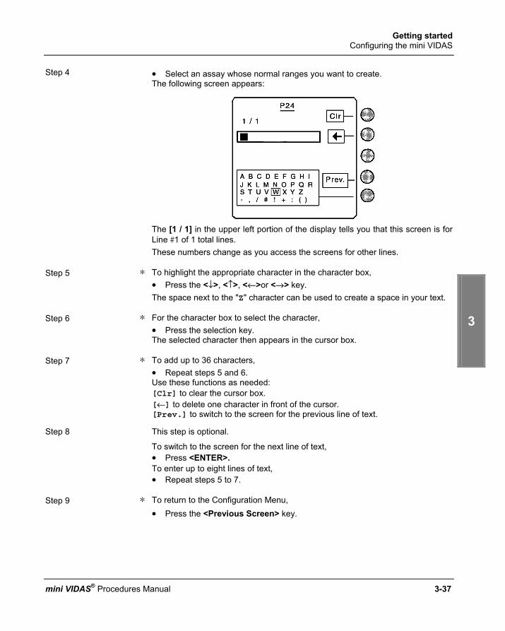
Getting started Configuring the mini VIDAS
1
2
3
4
5
mini VIDAS® Procedures Manual 3-37
Step 4 • Select an assay whose normal ranges you want to create.
The following screen appears:
The [1 / 1] in the upper left portion of the display tells you that this screen is for Line #1 of 1 total lines. These numbers change as you access the screens for other lines.
Step 5 ∗ To highlight the appropriate character in the character box,
• Press the <↓>, <↑>, <←>or <→> key. The space next to the "Z" character can be used to create a space in your text.
Step 6 ∗ For the character box to select the character,
• Press the selection key. The selected character then appears in the cursor box.
Step 7 ∗ To add up to 36 characters,
• Repeat steps 5 and 6. Use these functions as needed: [Clr] to clear the cursor box. [←] to delete one character in front of the cursor. [Prev.] to switch to the screen for the previous line of text.
Step 8 This step is optional.
To switch to the screen for the next line of text, • Press <ENTER>. To enter up to eight lines of text, • Repeat steps 5 to 7.
Step 9 ∗ To return to the Configuration Menu,
• Press the <Previous Screen> key.

Getting started Installing paper in the printer
3-38 mini VIDAS® Procedures Manual
I n s t a l l i n g p a p e r i n t h e p r i n t e r Use this procedure to load paper in the internal thermal printer.
Note: The paper for this printer is coated on only one side. If the printer does not print after the paper is installed, reorient the roll to expose the other side.
Step 1 • Select [Utility Menu] on the Main Menu. Step 2 • Select [Misc. Functions] on the Utility Menu.
The miscellaneous functions menu appears:
Step 3 • Select [Load Printer].
The following message appears: Load paper now (Press any key to quit)
Step 4 • Lift the printer door, located on the top of the instrument, above the keypad.
Step 5 • Retrieve the paper spindle from its slots and put it through the core of the
paper roll. Note: If you have just unpacked the mini VIDAS, there may be a piece of tape holding the
spindle. Remove and discard this tape.
Step 6 • Return the loaded spindle to the vertical slots in the print roll housing.
The paper engagement lever is in the LOWER end of its slot. Step 7 • Push the edge of the paper under the paper feed roller.
A sensor that detects the presence of the paper activates the paper roller.

Getting started Installing paper in the printer
1
2
3
4
5
mini VIDAS® Procedures Manual 3-39
Step 8 • Allow the roller to feed the paper.
It stops automatically after a few seconds. • Slide the paper engagement lever to the UPPER end of its slot.
IMPORTANT! The paper must be fed enough so that the leading edge extends under the plastic paper guide and out of the printer compartment so that it is exposed when you close the printer door. If necessary, select [Load Printer] again to feed more paper.
Step 9 • Hold the leading edge of the paper in one hand.
• With the other hand, close the printer door.
Your mini VIDAS is now ready for use!

Getting started Print screen
3-40 mini VIDAS® Procedures Manual
P r i n t s c r e e n
• Display the page you want to print.
• Press the key twice. The following screen appears:
• Select [Print Screen] to start printing.
• Press the key to go back to the previous screen.

mini VIDAS® Procedures Manual 4-1
4 Rout ine procedures
I n t r o d u c t i o n
This chapter contains the procedures you need to perform the routine operations of the mini VIDAS. The procedures in this chapter assume that you have performed the following: − Powered on the mini VIDAS. − Set the mini VIDAS configuration options defined in chapter 3. This chapter includes the following sections:
♦ Precautions for use of reagents ................................................................. 4-2 ♦ Basic mini VIDAS work flow....................................................................... 4-3 ♦ Planning a run............................................................................................ 4-8 ♦ Running assays ....................................................................................... 4-13 ♦ Calibration – Recalibration....................................................................... 4-27 ♦ Entering master lot data........................................................................... 4-33 ♦ Listing stored standards........................................................................... 4-43 ♦ Listing master lots .................................................................................... 4-45 ♦ Halting a section ...................................................................................... 4-46

Routine procedures Precautions for use of reagents
4-2 mini VIDAS® Procedures Manual
P r e c a u t i o n s f o r u s e o f r e a g e n t s
IMPORTANT! Store the reagent kits at 2-8°C. Allow the reagents to come to room temperature before use (refer to the package insert in the reagent kits). Do not use reagents after the expiration date. Do not mix reagents from different lots. Carefully reseal the SPR® pouch after use with the desiccant inside. Use powderless gloves. Carefully mix the standard, controls and samples before pipetting into the strip. Check that each SPR has a color-coded dot. If a SPR does not have its color-coded dot: − Reject the result corresponding to the defective SPR. − Check that the dot has not become stuck on the SPR block or the SPR
seal and if it has, then remove it. − Repeat the assay corresponding to the defective SPR. − Call bioMérieux ® Technical Assistance.
Specif ici t ies of the mini VIDAS blue
The mini VIDAS blue strip preparation tray can be used to bring the reagents to room temperature.
CAUTION! Never dispense samples into the reagent strips when they are on the strip preparation tray. The strip preparation tray should only be used for reagent strips. Do not place samples on it.

Routine procedures Basic mini VIDAS work flow
1
2
3
4
5
mini VIDAS® Procedures Manual 4-3
B a s i c m i n i V I D A S w o r k f l o w
Continued on next page
Step 1 Prepare sample
Step 2 Plan the run
Step 3 Fill sample well
Step 4 Place strips in the mini VIDAS
Step 5 Place SPRs in the mini VIDAS
Step 7 Close reagent strip cover
Step 6 Close SPR door

Routine procedures Basic mini VIDAS work flow
4-4 mini VIDAS® Procedures Manual
Fig. 4-1: Basic mini VIDAS work flow
This procedure outlines the common work flow steps that are used for all mini VIDAS assays. Sample preparation steps, which may vary from assay to assay, are covered in the package insert for each assay.
IMPORTANT! Always follow good laboratory practices and universal safety precautions when handling VIDAS assay kits.
Step 8 Run assays
Step 9 Results are printed automatically
Step 10 Remove the reagent strips and SPRs

Routine procedures Basic mini VIDAS work flow
1
2
3
4
5
mini VIDAS® Procedures Manual 4-5
Step 1 • Prepare samples as described in the appropriate assay package insert.
Step 2 • Determine the type of run required (refer to page 4-8 in this chapter for information on the type of runs and how to plan them).
Step 3 ∗ To fill a reagent strip, • Place the prepared samples, calibrators and controls in the wells on the
reagent strip. The sample is placed in the sample well as indicated in the package insert. The package insert specifies the volume of sample required to ensure proper performance of the assay.
CAUTION! Strips and SPRs should not be loaded in advance but just before the corresponding test is performed. In fact, preincubation in the sections can affect results. However, for certain tests which do require preincubation, the strips can be incubated in the instrument (refer to the corresponding reagent package insert).
IMPORTANT ! It is very important to respect the required volume indicated in the assay package insert. The sample must not contain any solid matter that could clog the tip of the SPR. Do not use the strips if the aluminum foil is damaged or if reagents are leaking, as this could affect the accuracy of test results. Always make sure you put the correct patient sample into the assigned strip. For optimum operation of the instrument, the SPR block and tray doors must be kept closed.

Routine procedures Basic mini VIDAS work flow
4-6 mini VIDAS® Procedures Manual
Step 4 ∗ To insert the reagent strip into the mini VIDAS, • Lift the cover of the reagent strip section.
• Holding it by its handle, insert a strip into its assigned test position.
• Slide the strip all the way back; you will feel it seat in the section channel. Step 5 ∗ To place a SPR in the mini VIDAS,
• Open the SPR block door. • Place a corresponding SPR in the SPR block position directly over the
reagent strip.
CAUTION! When placing the SPR in the SPR block position, do not apply pressure to the block position as this may cause the SPR to be ejected.
Nota: Check the position of SPRs and reagent strips. The SPR color-coded dot must match the dot on the corresponding reagent strip.
CAUTION! It is very important that all the SPRs corresponding to the assay you want to run are properly placed in the SPR block and that the dot on top has a hole. The mini VIDAS cannot detect the type of SPR used nor the absence or presence of SPRs.
∗ For the other reagent strips and SPRs, repeat steps 4 and 5. Step 6 • Close the SPR block door(s). Step 7 • Lower the reagent strip section cover(s). Step 8 • Run the assays. Step 9 ∗ At the end of the run:
− Reports are automatically generated at the printer. − The status of the sections used in the run changes from "Run" to "Unload". − The section door light starts flashing, also indicating that the reagent strips
and SPRs should be removed.

Routine procedures Basic mini VIDAS work flow
1
2
3
4
5
mini VIDAS® Procedures Manual 4-7
Step 10 • Remove the reagent strips from the section.
• Lift the SPRs out of their positions, making sure that they still have their color-coded dots.
IMPORTANT! If a SPR does not have its color-coded dot: − Reject the result corresponding to the defective SPR. − Check that the dot has not become stuck on the SPR block or the SPR
seal and if it has, then remove it. − Repeat the assay corresponding to the defective SPR. − Call bioMérieux Technical Assistance.
∗ When a SPR block door is open after SPRs are removed, − the status for the section is “Available”. − the section light stops flashing, indicating that the section is ready for a new
run.

Routine procedures Planning a run
4-8 mini VIDAS® Procedures Manual
P l a n n i n g a r u n
The mini VIDAS has two sections, each containing six positions. That means you can run a total of 12 single reagent strips, or 6 dual reagent strips, at the same time. In planning the number and types of assays to run, you must consider four additional factors: − Type of run required − Assay compatibility − Standards and controls − Master lot data
Type of run required The mini VIDAS allows two different types of runs. With the first type, the assays are defined in the mini VIDAS prior to the start of the run. With the second type, no definitions are made prior to the run. The information that the mini VIDAS requires is taken from the labels on the reagent strips during the initial steps of the run. The first type of run is referred to simply as a "Defined" run. The second type is called a "Load and Go" run.
Defined vs. load and go runs
In addition to the assay type, three parameters can be entered prior to starting a defined run: − Sample ID − A standard or control − A dilution factor These three parameters can be entered in a Load and Go run, but only after it has been started. Your workload and procedural requirements will determine the type of run you use.

Routine procedures Planning a run
1
2
3
4
5
mini VIDAS® Procedures Manual 4-9
Assay compatibi l i ty
When planning a run, you may need to decide whether you can run different assay types at the same time. The mini VIDAS allows you to run different assays in the two sections at the same time. However, for different assays to run in the SAME section, they must have the same protocol.
∗ To check if two assays are compatible, • Use the following procedure to view the screen display of the assay
compatibility list. Step 1 From any screen,
• Press the <?> key. A help screen appears. Step 2 • Press the <?> key a second time. The following screen appears:
Step 3 • Select [Assay compatibility list].
A list of assays appears on the screen. The assays listed in the same column are compatible with one another. If an assay is not on this list, it is not compatible with any other assay.

Routine procedures Planning a run
4-10 mini VIDAS® Procedures Manual
Standards and controls
Another part of your run planning is whether to include standards and controls.
Standards All single strip reagent assays require that a standard assay result be stored in the mini VIDAS. There are two conditions where a standard must be included in a run: − you are running an assay kit lot for the first time, − the previous standard for the lot you are using was run over 14 days ago
and has therefore expired. Note: Refer also to the procedure "Listing stored standards" on page 4-43 of this chapter.
Controls Positive and Negative Controls are provided in all VIDAS assay kits. Controls should be tested with each new lot or shipment to ensure that assay performance has not been altered throughout shipping storage. Controls should be tested routinely as specified by your laboratory’s regulatory guidelines.

Routine procedures Planning a run
1
2
3
4
5
mini VIDAS® Procedures Manual 4-11
Summary of the mini VIDAS software
MAIN MENU 1 - START SECTION 2 - STATUS SCREEN 3 - MASTER LOT MENU 4 - RESULTS MENU 5 - UTILITY MENU
1 - START SECTION Section A Section B All Sections
2 - STATUS SCREEN A Available B Available Display temperatures
3 - MASTER LOT MENU Read Master Lot Manual Master Lot Entry List Stored Stds. List Master Lots
4 - RESULTS MENU Validate LIS results Reprint Results Print Assay List

Routine procedures Planning a run
4-12 mini VIDAS® Procedures Manual
5 - UTILITY MENU Configuration Menu:
Set Dose Units User ID Report Header Set Date/Time Set Display Contrast Select Language Select Printer Internal Printer External Printer Set Date/Time Format Time separator Date separator Format Define Sample ID Character Sets Sample ID Set 1 Sample ID Set 1 Barcode Wand Sound Menu Misc LIS User Options
LIS Upload Enabled Warn About Missing Ids LIS auto validation
LIS Interface Options Communications Settings Timeouts & Limit Data Formats
Send Test Message Normal Ranges
Misc. Functions: Version Menu
Show Software Version Print Software Version Show Assay Version Print Assay Versions
Load Printer Update Park System Test Menu
Display Test Keypad Test Printer Test Audio Test
Section counters
Halt Section
View Saved Errors
On/Off line
Card Note
Assay Update

Routine procedures Running assays
1
2
3
4
5
mini VIDAS® Procedures Manual 4-13
R u n n i n g a s s a y s
CAUTION! To obtain a result, it is important to use a standard that is correct.
Assay requests
∗ There are three possibilities for running assays:
• Start a run without entering any IDs (when the assay is finished, there is no possibility of entering IDs). See "Starting a load and go run"on page 4-13 of this chapter.
• Enter IDs for the samples, standards, controls and if required, the assay codes and then start the run. See "Starting a defined run" on page 4-16 of this chapter
• Start a run and then enter IDs for the samples, standards, and controls.
CAUTION! When calibration is performed, the standard and/or controls must be identified. In this case, only possibilities 2 or 3 will be used.
Start ing a load and go run Use this procedure to start a run that does not require IDs for samples, standards or controls. The procedure assumes that all strips have been inoculated with appropriate samples. (See "Basic mini VIDAS work flow", on page 4-3 of this chapter).
IMPORTANT! It is very important to respect the required volume indicated in the assay package insert. Strips and SPRs should not be loaded in advance but just before the corresponding test is performed. In fact, preincubation in the sections can affect results. However, for certain tests which do require preincubation, the strips can be incubated in the instrument (refer to the corresponding reagent package insert).

Routine procedures Running assays
4-14 mini VIDAS® Procedures Manual
Step 1 ∗ To insert the reagent strips,
• Lift the cover of the reagent strip tray. • Holding a strip by its handle, insert it into its assigned test position. • Slide the strip all the way back; you will feel it seat in the section channel.
Step 2 ∗ To insert the SPRs,
• Open the SPR block door. • Place a SPR in the SPR block position directly over the corresponding
reagent strip.
Nota: Check the position of SPRs and reagent strips. The SPR color-coded dot must match the dot on the corresponding reagent strip.
CAUTION! It is very important that all the SPRs corresponding to the assay you want to run are properly placed in the SPR block and that the dot on top has a hole. The mini VIDAS cannot detect the type of SPR used nor the absence or presence of SPRs.
Step 3 • Close the SPR block door and the reagent strip tray cover. Step 4 • Select [Start Section] on the main menu.
The following screen appears:
The following selection options appear:
[Section A] [Section B] [All Sections]

Routine procedures Running assays
1
2
3
4
5
mini VIDAS® Procedures Manual 4-15
Step 5 This step has two options:
∗ To start one of the two sections,
• Select [Section A] or [Section B].
∗ To start section A and section B,
• Select all sections. Regardless of the option you choose, the following screen appears if two or more user IDs have been defined*:
Step 6 • Press a digit on the <Number Key> pad corresponding to the user ID assigned to this section.
The following message appears: Starting Section Please wait...
The display returns to the Main Menu.
* If only one user ID was defined, that ID appears on the assay report; if no user IDs were defined, no ID is included on
the assay report. See Configuring the mini VIDAS in Chapter 3 for more information.

Routine procedures Running assays
4-16 mini VIDAS® Procedures Manual
Start ing a def ined run This procedure includes all the steps required to define the tests in the mini VIDAS, load the strips and SPRs, and start the sections. It does, however, assume that all strips have been inoculated with appropriate samples. (See "Basic mini VIDAS work flow", on page 4-3 of this chapter).
Step 1 • Select [Status Screen] from the Main Menu. Step 2 • Select [Section A] or [Section B], depending on where you plan to
place strips and SPRs. Note: A section must have a status of “Available” in order for you to proceed.
See chapter 2 page 2-16 for a listing of status codes and their meanings.
After a section is selected, the section screen appears:
The numbers on the screen correspond to the six positions in the section.
Step 3 • Press the <Number Key> corresponding to the position where you want to
place a reagent strip. Note: Dual reagent strips MUST be placed in positions 1 & 2, 3 & 4, or 5 & 6. Placing one in
positions 2 & 3, for example, causes an error.
The position screen appears.

Routine procedures Running assays
1
2
3
4
5
mini VIDAS® Procedures Manual 4-17
Step 4 • Select [Assay].
Step 5 • Select [Select Assay].
An assay code list appears The assays that actually appear may be limited by the [Show All Assays] configuration option.
Note: If an assay has already been selected for the section, the assay code list only includes the assays compatible with the previously selected assay and with the other assays which have the same name.
Step 6 ∗ Press the <↓> key, if necessary, until the assay code you want appears. Step 7 • Select the assay code.
The position screen returns with the assay code now included.
Note: If this test is not a standard or control, go to Step 9.

Routine procedures Running assays
4-18 mini VIDAS® Procedures Manual
Step 8 (optional) This step has two options:
∗ If the test is to be a standard, The standard should be identified by S1 (or S2 for HBET) (S1 + S2 for certain assays, example : TSH3). If the kit includes one standard: • Select [S]: S1 is created automatically (or S2 depending on the test). • Repeat the same operation if you want to calibrate in duplicate or triplicate. If the kit includes two standards: • Select [S]. • Press a number key corresponding to the ID number for the standard. • Repeat the same operation if you want to calibrate in duplicate or triplicate.
Note: Multiple standards with the same ID number are considered to be replicates by the mini VIDAS. The number of replicates to be performed for each standard is indicated in the corresponding reagent package insert.
∗ If the test is to be a control, Controls should be run in the kit at the same time as the standard. • Select [C]. The following prompt appears:
Enter Control number (1-4) • Press a number key corresponding to the ID number for the control.
Step 9 • Select [Sample ID]. A screen similar to the following appears. In this example, it is the sample ID screen for section B, position 1:
The space next to the “Z” character can be used to create a space in your ID.

Routine procedures Running assays
1
2
3
4
5
mini VIDAS® Procedures Manual 4-19
Step 10 This step has two options:
∗ To enter the sample ID manually,
• Pres the <↑>, <↓>, <←> and <→> keys to highlight the appropriate character in the character box.
• Select the character. The character appears in the cursor box.
• Press the appropriate <Number Key> to place a number in the cursor box.
• Select one of the two sample ID character sets to place one of these character sets in the cursor box.
Note: See "Defining the sample ID character sets" on page 3-23 of chapter 3 for more information on sample ID character sets.
∗ To input the sample ID,
• You can use the bar code reader wand. Step 11 • Repeat step 10 until the sample ID for the test is complete.
Use these functions as needed: [Clr] to clear the cursor box. [←] to delete one character in front of the cursor.
Step 12 ∗ To return to the Position screen,
• Press the <Previous Screen> key. The sample ID now appears on the screen.

Routine procedures Running assays
4-20 mini VIDAS® Procedures Manual
Step 13 • Repeat steps 3 to 12 to define a test for the other positions in the section.
The following functions are also available in this procedure.
• Select [Assay] and then [Clear] on the screen to erase the inputs for a position, or to erase all the inputs for the entire section.
• Select: [Clear this position's setup only] or [Clear entire section's setup].
• Press <ENTER> after defining a test to define the same assay type for the
next position

Routine procedures Running assays
1
2
3
4
5
mini VIDAS® Procedures Manual 4-21
Step 14 When all the positions in a section are defined, press the <Previous Screen>
key to return to the section screen.
The following figure shows a section screen with information defined for all six positions:
• Make sure that the placement of the reagent strips matches the definitions
you entered in this procedure
IMPORTANT ! It is very important to respect the required volume indicated in the assay package insert . Strips and SPRs should not be loaded in advance but just before the corresponding test is performed. In fact, preincubation in the sections can affect results. However, for certain tests which do require preincubation, the strips can be incubated in the instrument (refer to the corresponding reagent package insert).
Step 15 • Insert the reagent strips.
• Lift the cover of the reagent strip tray.
• Holding a strip by its handle, insert it into its assigned test position.
• Slide the strip all the way back; you will feel it seat in the section channel.

Routine procedures Running assays
4-22 mini VIDAS® Procedures Manual
Step 16 • To insert a SPR,
• Open the SPR block door.
• Place a SPR in the SPR section position directly over the corresponding reagent strip.
Nota: Check the position of SPRs and reagent strips. The SPR color-coded dot must match the dot on the corresponding reagent strip.
CAUTION! It is very important that all the SPRs corresponding to the assay you want to run are present and properly placed in the SPR block and that the dot on top has a hole. The mini VIDAS cannot detect the type of SPR used nor the absence or presence of SPRs.
Step 17 • Close the SPR block door and the reagent strip tray cover. Step 18 This step has two options:
∗ To start the section
• Select [Start].
If two or more user IDs have been defined*, the following screen apepars:
• Go to step 19.
* If only one user ID was defined, that ID appears on the assay report; if no user IDs were defined, no ID is included on the assay report.

Routine procedures Running assays
1
2
3
4
5
mini VIDAS® Procedures Manual 4-23
∗ To return to the first status screen, • Press <Previous Screen>. From this screen you can define tests for the other section.
• Repeat steps 2 to 14.
Note: Sections can be started individually, as in Step 18 above.
They can also be started together from the Main Menu. The only difference is in defining the user ID. Sections started together will use the same user ID; those started individually can use different user IDs.
Step 19 • Press a digit on the <Number Key> pad corresponding to the user ID
assigned to this section. The following message appears:
Starting Section Please wait...
The first status screen then appears with the status of the started section now being "Barcode". This indicates the run has started and the instrument is reading bar code data from the reagent strips.
Step 20 ∗ To return to the Main Menu,
• Press <Previous Screen>.
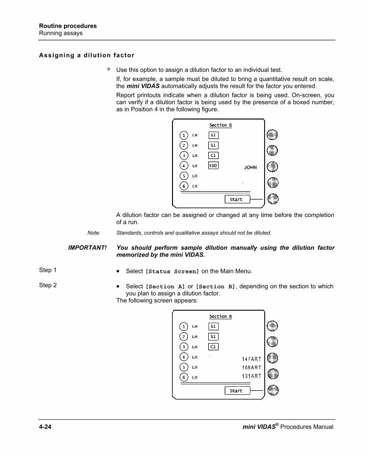
Routine procedures Running assays
4-24 mini VIDAS® Procedures Manual
Assigning a di lut ion factor
∗ Use this option to assign a dilution factor to an individual test. If, for example, a sample must be diluted to bring a quantitative result on scale, the mini VIDAS automatically adjusts the result for the factor you entered. Report printouts indicate when a dilution factor is being used. On-screen, you can verify if a dilution factor is being used by the presence of a boxed number, as in Position 4 in the following figure.
A dilution factor can be assigned or changed at any time before the completion of a run.
Note: Standards, controls and qualitative assays should not be diluted.
IMPORTANT! You should perform sample dilution manually using the dilution factor memorized by the mini VIDAS.
Step 1 • Select [Status Screen] on the Main Menu. Step 2 • Select [Section A] or [Section B], depending on the section to which
you plan to assign a dilution factor. The following screen appears:
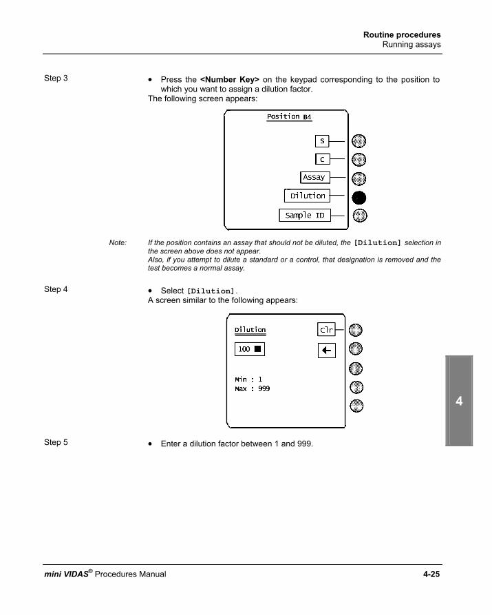
Routine procedures Running assays
1
2
3
4
5
mini VIDAS® Procedures Manual 4-25
Step 3 • Press the <Number Key> on the keypad corresponding to the position to
which you want to assign a dilution factor. The following screen appears:
Note: If the position contains an assay that should not be diluted, the [Dilution] selection in
the screen above does not appear. Also, if you attempt to dilute a standard or a control, that designation is removed and the test becomes a normal assay.
Step 4 • Select [Dilution].
A screen similar to the following appears:
Step 5 • Enter a dilution factor between 1 and 999.

Routine procedures Running assays
4-26 mini VIDAS® Procedures Manual
Step 6 • Press the <ENTER> key.
The screen returns to the position screen with the new dilution factor displayed, similar to the following:
Step 7 This step has two options:
∗ To return to the Section screen, • Press <ENTER>. • Repeat steps 3 to 6 to assign dilution factors to additional positions in the
section.
∗ To return to the Main Menu, • Press <Previous Screen>.

Routine procedures Calibration – Recalibration
1
2
3
4
5
mini VIDAS® Procedures Manual 4-27
C a l i b r a t i o n – R e c a l i b r a t i o n
The reagents are calibrated according to two different modes, depending on whether the assays are quantitative or qualitative. (see Appendix C on page 8-35).
Quantitative E.g. Ferritin, Rubella IgG ..... Calibration is performed at the factory for each new reagent lot and is entered into the insturment using a bar code included in each reagent kit. A "master curve" is thus stored in memory. The "master curve" can be readjusted by running a standard. Readjustment of the curve must be validated by testing the control(s) in the kit. Recalibration should be performed every 14 days.
Qualitative The result is interpreted by comparing the "test value" to one or two threshold values entered into the mini VIDAS.
Principles of cal ibrat ion using the mini VIDAS
Theoret ical principle
The principle consists of determining the mathematical equation which represents the calibration curve, i.e. the relationship between the RFV and the concentration of the standards. Well-defined reference solutions (standards) are used to make this determination. This calibration curve is established with at least 5 standards. It is valid between zero and the standard with the highest titer. 3 mathematical models can be used to establish the master lot curve: − 4 logistic parameters or Rodbard model a1 - a4
RFV = + a4
1 + (c / a3)a2 − polynomial ln (c) = a1 + a2 RFV + a3 RFV2 + a4 RFV3
− semi-log RFV = a1 + a2 ln(c)
c, represents the concentration a1, a2, a3, a4 are the mathematical parameters of the model. They are recalculated for each calibration.

Routine procedures Calibration – Recalibration
4-28 mini VIDAS® Procedures Manual
Principle appl ied to mini VIDAS
For the mini VIDAS, calibration is performed during the production of each new lot of SPRs and reagents The number of standards varies between 5 and 11 depending on the biological assay. Each lot is associated with a particular mathematical model. To determine the master curve, the standards are tested in seven different runs on the same mini VIDAS instrument. The mean curve of these seven runs becomes the master curve.
+++ ++ +++++
+++++
++++++
++++
++++
+++++
+++++
0
1000
2000
3000
4000
5000
6000
0 6 12 18 24 30 36 42 48 54
RFV
The master curve is specific for a certain manufacturing lot and biological parameter.
Master curve
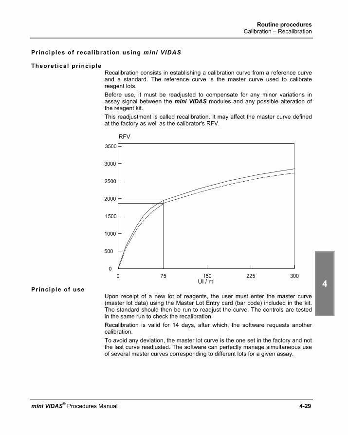
Routine procedures Calibration – Recalibration
1
2
3
4
5
mini VIDAS® Procedures Manual 4-29
Principles of recal ibrat ion using mini VIDAS
Theoret ical principle Recalibration consists in establishing a calibration curve from a reference curve and a standard. The reference curve is the master curve used to calibrate reagent lots. Before use, it must be readjusted to compensate for any minor variations in assay signal between the mini VIDAS modules and any possible alteration of the reagent kit. This readjustment is called recalibration. It may affect the master curve defined at the factory as well as the calibrator's RFV.
3500
3000
2500
2000
1500
1000
500
00 75 150 225 300
UI / ml
RFV
Principle of use
Upon receipt of a new lot of reagents, the user must enter the master curve (master lot data) using the Master Lot Entry card (bar code) included in the kit. The standard should then be run to readjust the curve. The controls are tested in the same run to check the recalibration. Recalibration is valid for 14 days, after which, the software requests another calibration. To avoid any deviation, the master lot curve is the one set in the factory and not the last curve readjusted. The software can perfectly manage simultaneous use of several master curves corresponding to different lots for a given assay.
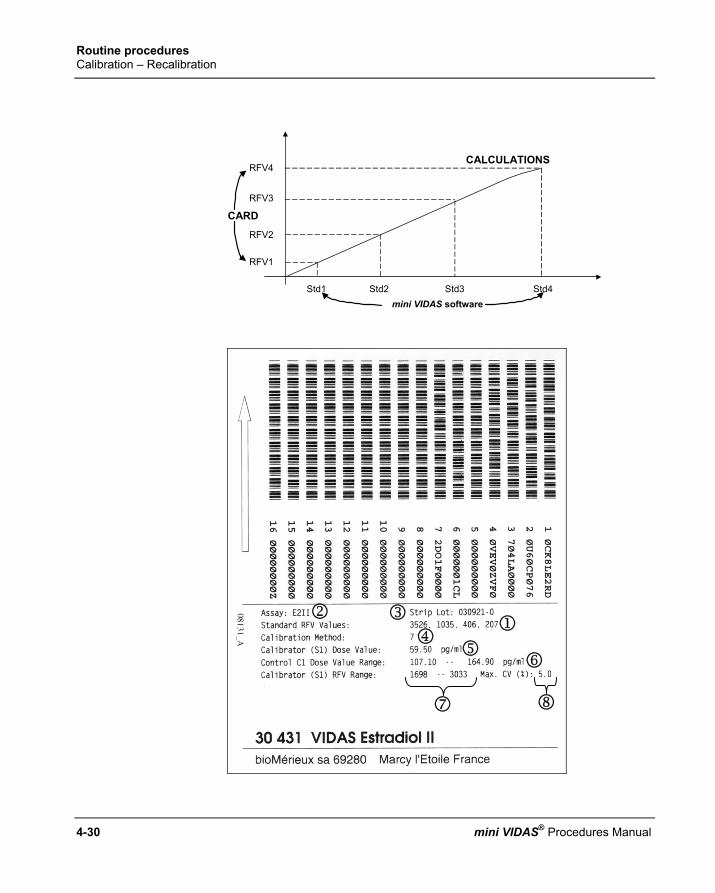
Routine procedures Calibration – Recalibration
4-30 mini VIDAS® Procedures Manual
RFV4
RFV3
RFV2
RFV1
Std1 Std2 Std3 Std4
CARD
CALCULATIONS
mini VIDAS software
2
6
7
4
8
5
3 1

Routine procedures Calibration – Recalibration
1
2
3
4
5
mini VIDAS® Procedures Manual 4-31
Establ ishing the master curve
∗ Each kit includes the master curve in the form of bar codes containing the following information:
1 4 RFV levels, corresponding to 4 standards defined in the software. The master curve is restored using 4 points; mathematically, this is sufficient in all cases. The levels of concentration of these 4 standards are known to the mini VIDAS software and are specific for each assay.
For instance, for FER, Std1 = 5, Std2 = 150, Std3 = 500, Std4 = 1200 ng / ml. The mini VIDAS software replots the total curve using the 4 pairs of concentrations and RFVs (master lot data).
∗ The remaining information includes:
2 the assay code,
3 the lot number of SPRs and reagents. This number corresponds to an expiration date. It is used to link the master curve data with the strip lot number,
4 mathematical model used to establish the master curve (7: Rodbard, 8: Polynomial, 9: Semilog),
5 the dose value for the standard (recalibrator) which is essential for calculating the correction factor. This value may vary slightly from one lot to another,
6 range values for the controls in the kit,
7 range values for the standard’s RFV,
8 maximum variation coefficient of the standard’s RFV duplicates or triplicates.
∗ All these data are coded in several lines of characters.

Routine procedures Calibration – Recalibration
4-32 mini VIDAS® Procedures Manual
How to cal ibrate
Master Lot data– Principle of cal ibrat ion
Before each new lot of reagents is used, master lot data must be entered into the instrument using the Master Lot Entry card (bar code) included in each kit. The master lot data includes:
A. assay code, B. kit lot number, C. acceptable range of values for the standard and controls to check
calibration quality: − range values for the controls included in the kit, − range values for the standard's RFV. − maximum variation coefficient of the standard's RFV duplicates or
triplicates. All these data are specific to an assay and a given lot. The standard must be identified by S1 or S2 (e.g. HBET) or S1 and S2 (e.g.TSH3).
Procedure
Each time a new lot of reagents is opened, after the master lot data have been entered, calibration should be performed every 14 days in duplicate or triplicate as indicated in the package insert. The control(s) should be tested in single. If the values obtained are not within the acceptable range, an error message appears on the result sheet.

Routine procedures Entering master lot data
1
2
3
4
5
mini VIDAS® Procedures Manual 4-33
E n t e r i n g m a s t e r l o t d a t a
All the mini VIDAS assays require input of Master Lot data prior to running a standard. The data includes several types of parameters that the mini VIDAS needs to run an assay. Master Lot data can be entered into the mini VIDAS either manually via the keypad, or automatically using the Master Lot Entry (MLE) card included in every assay kit. Master Lot Entry cards contain machine readable bar codes. The Master Lot Entry card is read by the mini VIDAS bar code reader inside the instrument. Manual entry of Master Lot data is a backup capability ot the automatic entry. The Master Lot Entry card contains alphanumeric equivalents to the machine-readable bar codes. Whether read by the instrument or entered manually, Master Lot data are checked by the mini VIDAS for accuracy, using a check code that is part of the data entry.
The figure below shows how the MLE card and its holder should be inserted into the mini VIDAS.

Routine procedures Entering master lot data
4-34 mini VIDAS® Procedures Manual
Automatic entry via the Master Lot Entry (MLE) card Use this procedure to enter Master Lot data from a Master Lot Entry (MLE) card. The Master Lot Entry card is placed into a specially designed holder and then inserted into a section of the mini VIDAS Module. Note that the data are presented in two forms: machine-readable bar codes and alphanumerics. This allows for manual data entry or correction if the machine cannot read all of the bar codes. Following is a sample card for a VZG assay kit.
5
1
2
3
4

Routine procedures Entering master lot data
1
2
3
4
5
mini VIDAS® Procedures Manual 4-35
Ref. Description
1 Bar codes These bar codes are read by the bar code reader in the mini VIDAS.
2 Alphanumeric codes In case of a read error by the machine, these codes can be manually entered.
3 Assay code and lot number
The data contained on the card applies only to this assay and lot.
4 Controls and standards data
5 Full assay name
Step 1 • Select [Master Lot Menu] in the Main Menu. Step 2 • Select [Read Master Lot] in the Master Lot Menu.
The following selections appear:
[Section A] [Section B]
Step 3 • Place the Master Lot data card in the reagent strip tray of the section you
will use. Note: The status of the selected section must be “AVAIL”.
Step 4 • Select the appropriate section.
The mini VIDAS reads the bar coded data from the card and the screen returns to the Master Lot Menu.

Routine procedures Entering master lot data
4-36 mini VIDAS® Procedures Manual
Error reading the card
∗ If the instrument is unable to read all the data on the card, the mini VIDAS beeps and an error message is generated.
• Make sure the MLE Card is properly oriented in the tray and perform this procedure again.
∗ If the instrument again fails to read the data,
• Perform the manual data entry procedure, found later in this section.

Routine procedures Entering master lot data
1
2
3
4
5
mini VIDAS® Procedures Manual 4-37
Manual master lot data entry (opt ion 2)
CAUTION! With manual entry of the MLE card there is a risk of error. Make sure that you enter the lines in exactly the same order as they appear on the MLE card.
There are two procedures for manual Master Lot data entry. The two cases in which you might enter data manually are: − to correct bar codes read incorrectly by the mini VIDAS, − to use manual entry as the first method.
Note: Data can be read using the bar code reader.
Case 1
Manual entry is used to correct bar codes misread by the mini VIDAS. Step 1 • Select [Master Lot Menu] in the Main Menu. Step 2 • Select [Manual Master Lot Entry] in the Master Lot Menu.
The follow screen appears:
Note the numbers "1/16" on the screen. They indicate that there is a total of 16 bar codes on the Master Lot data card, and, in the example shown, bar code # 1 is bad.
Step 3 To clear the bar code window of the message "bad.",
• Select [Clr]

Routine procedures Entering master lot data
4-38 mini VIDAS® Procedures Manual
Step 4 • Find the appropriate bar code on the Master Lot Data card.
The figure below shows a portion of a sample card with the 16 machine-readable bar codes and matching alphanumeric strings.
Step 5 • Enter the correct bar code using the bar code reader or type the characters of the bar code manually.
∗ For digits, - Use the appropriate <Number Key>.
∗ For letters, - Press the <↑>, <↓>, <←> and <→> keys to highlight the appropriate character
in the character box. - Select the character box. The digits and letters appear in the box as you enter them. Continue this for all nine characters in the bar code. Use these functions as needed: [Clr] to clear the cursor box. [←] to delete one character in front of the cursor. [Prev.] to go back to the previous bar code. (do not mistake this key for the <Previous Screen> key on the keypad).
Note: "O" and "I" are letters. "Ø" and "1" are the digits zero and one.

Routine procedures Entering master lot data
1
2
3
4
5
mini VIDAS® Procedures Manual 4-39
Step 6 ∗ When the bar code entry is complete,
• Press <Previous Screen>. The mini VIDAS checks the bar code. − If the bar code was entered correctly and there are no other errors, the
display exits to the Master Lot Menu and you have completed Master Lot Data entry.
Step 7 ∗ Print the Master Lot Data report showing the main characteristics of the assays.
Step 8 ∗ When the bar code entry is complete,
− If you entered the bar code incorrectly, or if other bar codes need to be corrected, the following prompt appears:
MLE Card data bad Edit again?
• Select [Yes] to continue the entry process. The manual bar code entry screen appears again. The digits, indicating the bar code number from 1 to 16, are displayed.
• Repeat steps 3 to 6 and correct the bar code(s) if necessary.

Routine procedures Entering master lot data
4-40 mini VIDAS® Procedures Manual
Case 2
Manual entry is the first method. Step 1 • Select [Master Lot Menu] in the Main Menu. Step 2 • Select [Manual Master Lot Entry] in the Master Lot Menu.
The following screen appears:
Note the numbers “1 / 16” on the screen. They indicate that there is a total of 16 bar codes on the Master Lot Data Card, and, in the example shown, you are entering bar code #1.
Step 3 • Enter the appropriate bar code.
The figure below shows a portion of a sample card with the 16 machine-readable bar codes and matching alphanumeric strings.

Routine procedures Entering master lot data
1
2
3
4
5
mini VIDAS® Procedures Manual 4-41
Step 4 • Enter the correct bar code using the bar code reader or type the characters
of the bar code manually.
∗ For digits, − Use the appropriate <Number Key>.
∗ For letters, − Press the <↑>, <↓>, <←> and <→> keys to highlight the appropriate
character in the character box.
− Select the character box.
The digits and letters appear in the box as you enter them. Continue this for all nine characters in the bar code. Use these functions as needed: [Clr] to clear the cursor box. [←] to delete one character in front of the cursor. [Prev.] to go back to the previous bar code. (do not mistake this key for the <Previous Screen> key on the keypad).

Routine procedures Entering master lot data
4-42 mini VIDAS® Procedures Manual
Step 5 ∗ When the bar code entry is complete,
• Press <Previous Screen>. The mini VIDAS checks the bar code.
− If you entered the bar code incorrectly, or if other bar codes need to be
corrected, the following prompt appears: MLE Card data bad Edit again?
• Go to step 6.
− If bar code # 16 is entered correctly, the display returns to the Master Lot Menu. Entery of this Master Lot Data is complete.
Step 6 ∗ Print the Master Lot Data report showing the main characteristics of the assays.
Step 7 ∗ To continue the entry process,
• Select [Yes]. The manual bar code entry screen appears again. Note the number indicating the bar code number, 1 to 16, and proceed by repeating steps 3 to 5.

Routine procedures Listing stored standards
1
2
3
4
5
mini VIDAS® Procedures Manual 4-43
L i s t i n g s t o r e d s t a n d a r d s
If you need to see the standards for a particular assay lot, perform the following procedure:
Step 1 • Select [Master Lot Menu] in the Main Menu.
Step 2 • Select [List Stored Stds].
An assay code list appears:
Step 3 (optional)
• Press the <↓> key until the assay code you want appears.

Routine procedures Listing stored standards
4-44 mini VIDAS® Procedures Manual
Step 4 • Select the assay code.
A screen similar to the following appears:
Step 5 This step has three options
∗ To view additional standards (if any) for this assay type,
• Press <ENTER>.
∗ To return to the Utility Menu,
• Press <Previous Screen>.
∗ To delete the stored standard shown,
• Select [Delete]. The following prompt appears:
Standard will be deleted. Are you certain?
Step 6 • Select [Yes] to delete the stored standard.
The program exits to the Utility Menu.

Routine procedures Listing master lots
1
2
3
4
5
mini VIDAS® Procedures Manual 4-45
L i s t i n g m a s t e r l o t s
Use this procedure to display the master lots for a particular assay. Step 1 • Select [Master Lot Menu] in the Main Menu.
• Press the <↓> key. Step 2 • Select [List Master Lots].
A list of assays appears for which Master Lot Data exists. Step 3 • Select an assay code for which you want to display Master Lot Data.
A screen similar to the following appears:
Note: If there is more than one lot having master lot data, a lot selection screen appears first.
Step 4 • Press any key to return to the Assay Code List. Step 5 This step has three options:
∗ Select another assay code for which you want to display Master Lot data.
• Go to step 4.
∗ To return to the Main Menu, • Press <ENTER>.

Routine procedures Halting a section
4-46 mini VIDAS® Procedures Manual
H a l t i n g a s e c t i o n
CAUTION! You must discard the strips and SPRs that are in the halted section.
Use this procedure to stop the processing of one or both sections. Step 1 • Select [Utility Menu] in the Main Menu.
Note: A halt option is also available on the first status screen, accessed via the [Status Screen] selection in the Main Menu. This halt option is only available while a section is running.
Step 2 • Select [Halt Section] in the Utility Menu.
The following selections appear: [Section A] [Section B]
Step 3 • Select one of the sections to halt.
The following selections appear: [Halt (clear setup)] [Halt (retain setup)]
Step 4 This step has two options:
∗ To halt the section and erase the tests defined in the positions,
• Select the [clear setup] option. Use this option when the tests will not be run again.
∗ To halt the section and retain the tests defined in the positions,
• Select the [retain setup] option. Use this option when the tests will be run again. The Utility Menu appears again.
Step 5 ∗ To return to the Main Menu,
• Press <Previous Screen> twice.

mini VIDAS® Procedures Manual 5-1
5 Resul ts and repor ts
I n t r o d u c t i o n
This chapter covers two aspects of the data produced by the mini VIDAS: how it is analyzed by the onboard computer, and how the results are reported. The following procedures are described in this chapter:
♦ Analysis methods....................................................................................... 5-1 ♦ The assay report ........................................................................................ 5-6 ♦ Assay report errors .................................................................................. 5-11 ♦ Reprinting an assay report ....................................................................... 5-12 ♦ Validating LIS results ............................................................................... 5-15 ♦ Printing the mini VIDAS assay list............................................................ 5-18
A n a l y s i s m e t h o d s
The mini VIDAS uses several different methods to calculate results. There are three basic categories of analysis methods: − Patient to standard.
A comparison of the Relative Fluorescence Value (RFV) of the test sample to that of a standard. This method is used in single reagent strip qualitative, and most semi-quantitative assays.
− Patient to reference.
A comparison of the RFV of the test sample to that of a reference blank. This method is used in dual reagent strip qualitative assays.
− Curve fitting equations.
The RFV of a test sample is mathematically placed on a calibration curve. This method is used for all quantitative, and some semi-quantitative assays.

Results and reports Analysis methods
5-2 mini VIDAS® Procedures Manual
Terminology
The following terms are used in the discussion of analysis methods: Background The reading taken on the optical cuvette during the preprocessing phase of a
run. It represents the fluorescence of substrate alone.
RFV - Relative Fluorescence value
This is the fluorescence reading of a reagent strip minus the background.
Reference The first strip of a Dual Reagent strip pair; a specific reaction cannot be performed with this strip alone.
Standard For qualitative and semi-quantitative assays, this is a solution of known RFV against which the RFV of a test sample can be compared. For a quantitative assay, it is a solution with a known concentration of analyte that is used to calibrate a standard curve.
Test value In qualitative and semi-quantitative assays, it is the quantity calculated according to the analysis method. The test value is compared to a set of thresholds to generate the assay result.
Threshold Experimentally determined test values for qualitative and quantitative assays that translate the test value into a clinically significant Result. Results used in the mini VIDAS are: − Positive. There is a clinically significant level of analyte in the test sample.
− Negative. A clinically significant level of analyte is not present in the test sample.
− Equivocal. This result falls in the zone between the Positive and Negative. The test value obtained is close to both Positive and Negative results. Equivocal results suggest, therefore, that a test be rerun.

Results and reports Analysis methods
1
2
3
4
5
mini VIDAS® Procedures Manual 5-3
Quali tat ive assays: single reagent str ips
Two analysis methods are used for single reagent strip qualitative assays: the P/S method and the P-S method. In these methods, the “P” stands for the RFV of the test sample and the “S” stands for the RFV of a standard.
Assay calibration Single reagent strip assays are calibrated using a standard supplied with the
assay kit. A standard should be run the first time the assay kit lot is used. If replicate standards are run, their values are averaged. The standard result obtained can be used for a programmed period of days. After that, the software automatically expires the standard, requiring that you run another from the same lot.
P/S method For assays that use the P/S method, the test value is calculated from the ratio of the sample RFV to that of the standard RFV.
RFV (tested sample) = 2158 RFV (standard) = 2177 Test value (VT) = 2158/2177 = 0.99
P-S method For assays that use the P-S method, the test value is calculated from the difference between the sample RFV and the standard RFV.
RFV (tested sample) = 1774 RFV (standard) = 1689 Test value (VT) = 1774 - 1689 = 85
In both the P/S and P-S methods, the result of the assay is determined by comparing the test value to a set of preprogrammed thresholds. For every assay type, there is a high and low threshold value. The assay result is interpreted from the test value as follows:
If the test value is: the result is: ≥ high threshold positive
Assay result
< high threshold and ≥ low threshold
equivocal
< low threshold negative
For some qualitative assays (e.g. TOXO Competition, anti-HBc total), the result of the test value will be negative if the test value is ≥ to the high threshold.
Nota: Certain tests interpret the results using specific algorithms, e.g.: HIV5.

Results and reports Analysis methods
5-4 mini VIDAS® Procedures Manual
Quali tat ive assays: dual reagent str ips
Two analysis methods are used for dual reagent strip qualitative assays: the P/N method and the P-N method. In these methods, the “P” stands for the RFV of the test sample and the “N” stands for the RFV of a reference.
Assay calibration Dual reagent strip assays do not require separate calibration standards.
Instead, the reference strip serves the same purpose.
P/N method For assays that use the P/N method, the test value is calculated from the ratio of the sample RFV to that of the reference RFV.
RFV (tested sample) = 2158 RFV (reference) = 2177 Test value (VT) = 2158/2177 = 0.99
P-N method For assays that use the P-N method, the test value is calculated from the difference between the sample RFV and the reference RFV.
RFV (tested sample) = 1774 RFV (reference) = 1689 Test value (VT) = 1774 - 1689 = 85
In both the P/N and P-N methods, the result of the assay is determined by comparing the test value to a set of preprogrammed thresholds. For every assay type, there is a high and low threshold value. The assay result is interpreted from the test value as follows: If the test value is: the result is: ≥ high threshold positive
Assay result
< high threshold and ≥ low threshold
equivocal
< low threshold negative
Results and reports Analysis methods
1
2
3
4
5
mini VIDAS® Procedures Manual 5-5
Quanti tat ive assays
Quantitative mini VIDAS assays use a Calibration Curve to determine analyte concentrations in test samples. Three basic steps are required to run quantitative assays:
Step 1 • Enter the data for the calibration curve into the mini VIDAS.
The data, called the Master Lot Data, are supplied with the assay kit and are applicable for all tests run using this particular assay kit lot.
Step 2 • Calibrate the calibration curve using the standard supplied with the assay
kit.
This adjusts the calibration curve to your mini VIDAS.
Note: Although standards can be run after test samples have completed, it is recommended that they be run either before or with test samples from the same assay kit lot. If an assay has two calibrators, both must be run at the same time.
Step 3 • Run the test samples. Calibration curve For every quantitative assay, a set of standards is run in bioMérieux®
laboratories from which concentration vs. fluorescence is plotted. To ensure accuracy, the set of standards is prepared from the serial dilution of a standard considered to be the gold standard (WHO or physical measurement). The results of these assays are used to construct a curve. Then, using curve fitting methods, an equation for the curve is determined. The curve is called the calibration curve for the assay, and the equation is the tool the mini VIDAS uses to calculate results.
Master Lot data Each assay kit is accompanied by a Master Lot Data card. When the data from this card are entered, you are entering the calibration curve for the assay.
Recalibration The final calibration step for a quantitative assay is to run a standard that is supplied with the assay kit. Since the standard is a known quantity (it is entered with the Master Lot Data), the software can make any final adjustments to the calibration curve that may be needed. Since the characteristics of the reagents in an assay kit may vary over time, the mini VIDAS software automatically expires a standard after 14 days. To recalibrate, you run another standard from the same assay kit lot.
Note: Certain tests interpret the results using specific algorithms.

Results and reports The assay report
5-6 mini VIDAS® Procedures Manual
T h e a s s a y r e p o r t
When the run for a section is completed, the mini VIDAS automatically prints an assay report. The report is printed on the internal printer, by default, or on the optional external printer, depending on how the appropriate configuration option is set. All assay reports are similar, but not identical. Slight differences occur, depending on the assay type. The following subsections describe parts of the report.
Report reader The figure below shows a sample of a report header that contains information
common to all reports.
Note: The line numbers in the figure do not appear on an actual report.

Results and reports The assay report
1
2
3
4
5
mini VIDAS® Procedures Manual 5-7
Line Description
1
The report title, mini VIDAS Report.
2 The custom report header you can enter in the appropriate configuration option.
3 The identity of the section, A or B.
4 Date and time the assay completed.
5 Technologist ID, from the appropriate configuration option.
6 Name (and code) of the assay.
7 Version of the mini VIDAS software (Ver).
8 Assay kit lot number.
9* Information on the standard used, including:
10* Date and time the standard was run.
11* Mean RFV of the standard.
* Lines 9, 10, and 11 do not appear on reports for dual reagent strip Assays.
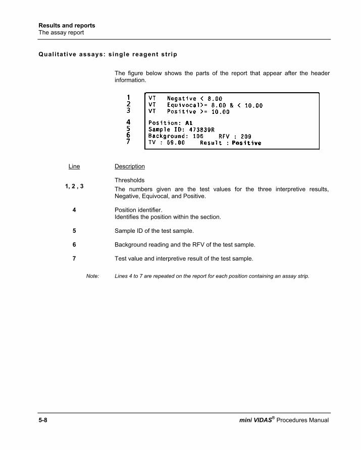
Results and reports The assay report
5-8 mini VIDAS® Procedures Manual
Quali tat ive assays: single reagent str ip The figure below shows the parts of the report that appear after the header information.
Line Description
1, 2 , 3
Thresholds The numbers given are the test values for the three interpretive results, Negative, Equivocal, and Positive.
4 Position identifier. Identifies the position within the section.
5 Sample ID of the test sample.
6 Background reading and the RFV of the test sample.
7 Test value and interpretive result of the test sample.
Note: Lines 4 to 7 are repeated on the report for each position containing an assay strip.

Results and reports The assay report
1
2
3
4
5
mini VIDAS® Procedures Manual 5-9
Quali tat ive Assays: dual reagent str ip The figure below shows the parts of the report that appear after the header information.
Line Description
1, 2 , 3 Thresholds The numbers given are the test values for the three interpretive results, Negative, Equivocal, and Positive.
4 Position identifier. Identifies the position within the section.
5 Background reading and RFV of the reference strip
6 Identifies the position of the test strip.
7 Sample ID of the test sample.
8 Background reading and RFV of the test strip.
9 Test value and interpretive result of the test sample.
Note: Lines 4 to 9 are repeated on the report for each position containing an assay strip.

Results and reports The assay report
5-10 mini VIDAS® Procedures Manual
Quanti tat ive assays The following figure shows the parts of the report that appear after the header information.
Line Description 1
Position identifier. Identifies the position within the section.
2 Sample ID of the test sample.
3 Background reading and the RFV of the test sample.
4 Quantitative test result.
Note: Lines 1 to 4 are repeated on the report for each position containing an assay strip.

Results and reports Assay report errors
1
2
3
4
5
mini VIDAS® Procedures Manual 5-11
A s s a y r e p o r t e r r o r s
The mini VIDAS assay report is designed to display error messages whenever a result does not conform to the internal requirements that are programmed for each assay. On the report, any values found to be outside control ranges are footnoted. An error message is then printed at the bottom of the report. Following is an example.
Ref. Description
1 Footnoted value. Note the “§” symbol next to the value. Different symbols are used for different error messages.
2 Footnote and error message. In this case, the error message is: "High reading"
3 The test result has been flagged as "INVALID" due to the nature of the error.
Note: See chapter 7 for a listing of the error messages.

Results and reports Reprinting an assay report
5-12 mini VIDAS® Procedures Manual
R e p r i n t i n g a n a s s a y r e p o r t
Note: Only those tests stored in the mini VIDAS memory are available for reprinting. If the mini VIDAS is turned off, stored results are no longer available.
mini VIDAS can store up to 48 results. For example, all 48 results can be from one section, or they can be divided between the two sections in any combination. The total, however, cannot exceed 48 (6 results x 8 sections). The storage system works on a “First In, First Out” basis. This means that the results of the last eight sections are the ones that are stored. When the results of the ninth section are stored, the first results of the first section to be stored are deleted.
Step 1 • Select [Results Menu] in the Main Menu. Step 2 • Select [Reprint Results] in the Results Menu.
A screen similar to the following appears:
Step 3 • Select one or more sections to reprint
Note: The symbol appears in the box for the selected section(s).

Results and reports Reprinting an assay report
1
2
3
4
5
mini VIDAS® Procedures Manual 5-13
Step 4 ∗ To print your selection,
• Press <ENTER>. The following prompt appear:
Edit the data before reprinting?
This enables you to view the assays run before reprinting results. Step 5 This step has two options:
∗ To reprint the selected section,
• Select [No]. The display returns to the Results Menu. After a few seconds, the results print out.
• Go to step 8.
∗ To view one or more positions in a section,
• Select [Yes]. The following screen appears
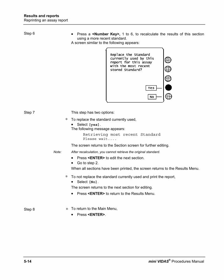
Results and reports Reprinting an assay report
5-14 mini VIDAS® Procedures Manual
Step 6 • Press a <Number Key>, 1 to 6, to recalculate the results of this section
using a more recent standard. A screen similar to the following appears:
Step 7 This step has two options:
∗ To replace the standard currently used, • Select [yes]. The following message appears:
Retrieving most recent Standard Please wait....
The screen returns to the Section screen for further editing.
Note: After recalculation, you cannot retrieve the original standard.
• Press <ENTER> to edit the next section. • Go to step 2. When all sections have been printed, the screen returns to the Results Menu.
∗ To not replace the standard currently used and print the report, • Select [No]. The screen returns to the next section for editing. • Press <ENTER> to return to the Results Menu.
Step 8 ∗ To return to the Main Menu,
• Press <ENTER>.

Results and reports Validating LIS results
1
2
3
4
5
mini VIDAS® Procedures Manual 5-15
V a l i d a t i n g L I S r e s u l t s You can access results to be uploaded when the option "LIS auto validation" is not activated. The mini VIDAS software has a unidirectional interface which allows patient results to be uploaded to the Laboratory Information System (LIS). Use this procedure to validate results before sending them to the LIS.
Step 1 • Select [Results Menu] in the Main Menu. Step 2 • Select [Validate LIS results] in the Results Menu
A screen similar to the following appears.
Ref. Description
1: Section number This label shows you are looking at assays that were run in section A.
2 : Date / time This label shows you the date and time the results were completed.
3 : Sample identifier This indicates the sample ID.
4 : Send A selection option to upload results to the LIS queue.
5 : Check boxes When appears, the position is validated for LIS upload. The position is validated by default except in the following cases: − expired reagent kit lot, − expired calibration standard, − result based on calibration with a single standard, When a result is determined to be invalid, it is shown on the screen but does not include a check box.
6 : Position numbers These numbers identify the six positions in the section.
7 : Assay code This is the code of the assay being run in a position.

Results and reports Validating LIS results
5-16 mini VIDAS® Procedures Manual
Step 3 ∗ To validate or not validate a position, press the <Number> key that
corresponds to that position. Step 4 This step has four options:
∗ To upload the results to the LIS, • Select [Send].
The screen will display the other results awaiting validation, if any. • Repeat step 4. When all the validated results have been uploaded, the screen returns to the Results Menu.
∗ To withhold from uploading a result to the LIS when the is present, • Press the <Number Key> corresponding to the position number.
∗ The will be removed indicating that the test result will not be uploaded to the LIS. • Repeat step 4.
∗ To delete the remaining non-validated LIS upload data, • Press <ENTER>. The following screen appears:
• Go to step 5.
∗ To abort the validation, • Press <Previous Screen>. The following message appears:
Validation aborted. Current Section’s results NOT validated.
The screen returns to the Results Menu.
Note: There cannot be more than 8 sections in the LIS validation queue. If this queue is full, a warning message will appear when you start additional assays. The message will warn you that the assay you are about to start will not be placed in the LIS validation queue unless you validate some results. However, the results will still be printed.

Results and reports Validating LIS results
1
2
3
4
5
mini VIDAS® Procedures Manual 5-17
Step 5 This step has two options:
∗ To delete the remaining non-validated LIS upload data,
• Select [Yes]. The screen returns to the Results Menu.
∗ To not delete the remaining non-validated LIS upload data,
• Select [No]. The screen will display the other results awaiting validation, if any,
• Go to step 4. Step 6 ∗ To return to the Main Menu,
• Press <ENTER>.
Note: A result can only be uploaded once (unless the section results are reprinted). Caution: if you turn off the instrument, the memory will refresh.

Results and reports Printing the mini VIDAS assay list
5-18 mini VIDAS® Procedures Manual
P r i n t i n g t h e m i n i V I D A S a s s a y l i s t
Use this procedure to print a list of the mini VIDAS assays that have Master Lot Data loaded on your mini VIDAS. The assay list includes the complete name of each assay and its assay code. Assays in the list are grouped by compatible protocols.
Step 1 • Select [Results Menu] in the Main Menu. Step 2 • Select [Print Assay List] in the Results Menu.
The following message appears for a moment: Constructing assay list printout. Please wait
The assay list then begins to print and the display returns to the Results Menu. A portion of an assay list printout appears below. Note that the assays are grouped by compatible protocols.

mini VIDAS® Procedures Manual 6-1
6 Miscel laneous operat ions
I n t r o d u c t i o n
This chapter contains a number of procedures that have been segregated from the other more frequently performed procedures. The following procedures are described in this chapter:
♦ Taking a section off line ............................................................................. 6-2 ♦ Changing factory settings .......................................................................... 6-3 ♦ Testing the mini VIDAS instrument ............................................................ 6-7 ♦ Updating an assay ................................................................................... 6-10 ♦ Displaying the mini VIDAS software version ............................................ 6-15 ♦ Printing the mini VIDAS software version ................................................ 6-16 ♦ Displaying the assay version ................................................................... 6-17 ♦ Section counters ...................................................................................... 6-19 ♦ Printing the assay version........................................................................ 6-20 ♦ Updating the mini VIDAS software via the memory card ......................... 6-21 ♦ Verifying the memory card data ............................................................... 6-24 ♦ Shipping the mini VIDAS.......................................................................... 6-25

Miscellaneous operations Taking a section off line
6-2 mini VIDAS® Procedures Manual
T a k i n g a s e c t i o n o f f l i n e
Use this procedure to take a section off-line. An off-line section is not available for running assays. The operating temperature remains the same whether a section is off-line or on-line.
Note: Use the same procedure to place an off-line section on-line. The section will be available for use immediately after it has been put back on-line.
Step 1 ∗ In the Main Menu, • Select [Utility Menu] • Press the <↑> and <↓> keys until the submenu you want appears on the
screen. Step 2 • Select [On/Off line].
The following selections appear: [Section A] [Section B]
Step 3 • Select one of the sections to place off-line.
The display returns to the previous menu.
Note: You can confirm the off-line status of a section by selecting [Status Screen] on the main menu. The first screen shows the status of each section.
Step 4 ∗ To return to the Configuration Menu,
• Press <Previous Screen>.

Miscellaneous operations Changing factory settings
6
7
8
9
10
mini VIDAS® Procedures Manual 6-3
C h a n g i n g f a c t o r y s e t t i n g s
CAUTION! Configuration parameters should only be modified by trained and qualified personnel. Any modification to configuration parameters may lead to problems when the system is used or cause it to operate in an unexpected manner. Make sure that modifications are necessary and justified.
The factory settings control various physical parameters that affect the keypad and display screen. This section contains the procedures needed to change these parameters from the values set by bioMérieux.
Note: We suggest that you use the mini VIDAS for several days before changing any of the settings. After that time, if you find that any settings do not suit you, you can make the necessary adjustments.
Accessing the factory sett ings All of the factory-set parameters are found on the Configuration Menu. Each procedure in this section, therefore, begins with a selection on the Configuration Menu. Refer to the following diagram for accessing the Configuration Menu.

Miscellaneous operations Changing factory settings
6-4 mini VIDAS® Procedures Manual
Main Menu
Utility Menu
Configuration Menu
Fig. 6-1: Accessing the Configuration Menu
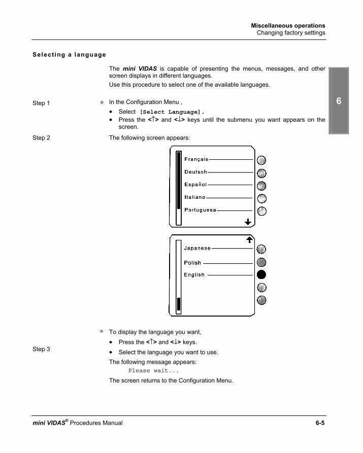
Miscellaneous operations Changing factory settings
6
7
8
9
10
mini VIDAS® Procedures Manual 6-5
Selecting a language
The mini VIDAS is capable of presenting the menus, messages, and other screen displays in different languages. Use this procedure to select one of the available languages.
Step 1 ∗ In the Configuration Menu , • Select [Select Language]. • Press the <↑> and <↓> keys until the submenu you want appears on the
screen.
Step 2 The following screen appears:
∗ To display the language you want,
• Press the <↑> and <↓> keys. Step 3 • Select the language you want to use.
The following message appears: Please wait...
The screen returns to the Configuration Menu.

Miscellaneous operations Changing factory settings
6-6 mini VIDAS® Procedures Manual
Main Menu
Utility Menu
Misc. Functions Menu
Test menu
Fig. 6-2: Accessing the Test Menu

Miscellaneous operations Testing the mini VIDAS instrument
6
7
8
9
10
mini VIDAS® Procedures Manual 6-7
T e s t i n g t h e m i n i V I D A S i n s t r u m e n t There are a number of simple tests that the mini VIDAS can perform on itself. They provide a quick and easy way to test the display, the keypad, the printer, and the audio output. It is not necessary to perform any of these tests on a routine basis. They may be needed should it become necessary to troubleshoot a problem in the mini VIDAS.
Accessing the tests All of the hardware tests are found on the Test Menu. Each procedure in this section, therefore, begins with a selection on the Test Menu. Refer to the diagram opposite for accessing the Test Menu.
Testing the display The mini VIDAS display screen is composed of several hundred individual points called pixels. Letters and other characters are formed by darkening the individual pixels in a pattern that forms the character. The display test darkens all the pixels on the display. It begins with the first vertical column on the left side of the screen, quickly moving towards the right, column by column. The failure of any pixel to darken can easily be seen.
Step 1 • Select [Display Test] in the Test Menu. The screen clears initially, and then begins to darken, from left to right, as described above.
Step 2 ∗ When the entire screen has darkened, inspect it for pixels that have failed to darken. They appear as “holes” in an otherwise dark screen.
Step 3 ∗ To return to the Test Menu, • Press <Previous Screen>.
Decrease in the intensity of display (only concerns mini VIDAS blue)
The mini VIDAS blue screen is equipped with a backlight system which improves the luminosity of the display.
∗ If the intensity decreases considerably or becomes irregular, call bioMérieux® Technical Assistance or your local bioMérieux representative.
Nota: The running of the mini VIDAS blue is in no way affected.

Miscellaneous operations Testing the mini VIDAS instrument
6-8 mini VIDAS® Procedures Manual
Testing the keypad
This test ensures that every key on the keypad is making a proper connection to the mini VIDAS. The test requires that you press every key on the keypad. The mini VIDAS responds with a symbol for each key on the display. The only exception to this pattern is the <?> key, which activates the help screen, as it normally does.
Step 1 • Select [Keypad Test] in the Test Menu.
The screen clears except for the title: Keypad Test
Step 2 • Press each key on the keypad.
When you are done, the display should be similar to the following:
Note: The last key press ends the test and returns the display to the Test Menu. You therefore
do not see that key’s symbol on the screen.
∗ After the last key is pressed, the message: Keypad okaya
Press any key to continue confirms a passed test.
∗ Should it be otherwise, call bioMérieux Technical Assistance.

Miscellaneous operations Testing the mini VIDAS instrument
6
7
8
9
10
mini VIDAS® Procedures Manual 6-9
Testing the printer Testing the printer is a matter of sending a string of known characters and ensuring that those characters are printed. There are two printer tests, one each for an internal and external printer. The test you use depends on what kind of printer your mini VIDAS is configured to use.
Note: See "Configuring the mini VIDAS" on page 3-11 of chapter 3 for information on selecting a printer.
• Select [Printer Test] in the Test Menu
The printer should immediately begin to print the following test pattern:
• Before starting, make sure that the external printer can be connected and
that the connection cord is properly connected. Failure of the printer to reproduce the test pattern constitutes a failure of this test.
Testing the audio output This procedure tests the audio output for the mini VIDAS’s beep.
• Select [Audio Test] in the Test Menu.
The mini VIDAS should respond with the beep tone.
Note: The display does not change during this test.
Miscellaneous operations Updating an assay
6-10 mini VIDAS® Procedures Manual
U p d a t i n g a n a s s a y
This section deals with assay updating to be performed on the mini VIDAS. This update gives you the possibility to use the complete range of VIDAS reagents by updating the VIDAS assay protocols.
Purpose of the assay update
IMPORTANT! This function enables you to transfer assay data to the mini VIDAS instrument when a new assay is used or when an existing assay is updated.
Updat ing
IMPORTANT! The update is stored in the mini VIDAS for further use of the assays.
Prel iminary instruct ions
∗ Before performing the update, make sure that:
− no assays are running,
− no reagents (strips and SPRs) remain in the strip sections and SPR blocks,
− printing is not in progress,
− the bar code reader provided for this update has been installed and configured. If not, see section "Installing the bar code reader" on page 8-41 of the manual.
− the reagent kit package insert is in good condition; to be readable the bar codes must be complete, unstained, and untorn. If they are not, call bioMérieux Technical Assistance or your local bioMérieux representative.

Miscellaneous operations Updating an assay
6
7
8
9
10
mini VIDAS® Procedures Manual 6-11
Reading assay update card bar codes
∗ In the Utility Menu,
• Select [Assay Update]. The following screen appears:
∗ If the data has to be sent to the LIS or reprinted,
• Select [No]. • Follow the instructions for sending or printing data before the update.
∗ Otherwise, • Select [Yes]. The following message appears:
Please wait...
The assay update card bar code screen is displayed:
Fig. 6-3: Assay update card bar code screen
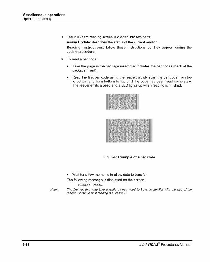
Miscellaneous operations Updating an assay
6-12 mini VIDAS® Procedures Manual
∗ The PTC card reading screen is divided into two parts: Assay Update: describes the status of the current reading. Reading instructions: follow these instructions as they appear during the update procedure.
∗ To read a bar code:
• Take the page in the package insert that includes the bar codes (back of the package insert).
• Read the first bar code using the reader: slowly scan the bar code from top to bottom and from bottom to top until the code has been read completely. The reader emits a beep and a LED lights up when reading is finished.
Fig. 6-4: Example of a bar code
• Wait for a few moments to allow data to transfer. The following message is displayed on the screen:
Please wait…
Note: The first reading may take a while as you need to become familiar with the use of the reader. Continue until reading is sucessful.

Miscellaneous operations Updating an assay
6
7
8
9
10
mini VIDAS® Procedures Manual 6-13
The reading screen is updated. It shows: − The total number of bar codes to be read and the number of the code
already read. The codes may not necessarily be read in numerical order.
− The number of codes still to be read to complete the update.
• Read the second bar code using the bar code reader.
• Wait for a few moments to allow transfer of the data contained in the code.
∗ If necessary, repeat the reading and waiting steps until all the codes required to update the protocol have been read.
Nota: The number of bar codes to be read for the update depends on the protocol.
∗ When reading is complete, a summary of the update status is displayed on the screen.
Fig. 6-5: Status after reading

Miscellaneous operations Updating an assay
6-14 mini VIDAS® Procedures Manual
• Select [Confirm to quit]to validate the update. The following message appears:
Please wait...
• Wait a few moments for the data to be saved. The Utility Menu is displayed. The update is complete.
∗ To return to the main menu, • Press <Previous screen>.
∗ An assay update report is printed:
∗ Bar code reading may fail if
− The code was not correctly read by the reader. − The code is unreadable (incomplete, stained, or torn). − The code read does not belong to the series of codes for the current update.
You should only read codes belonging to the same series.
∗ If bar code reading fails, a warning message is displayed.
• Solve the problems described in the message.
• Repeat the bar code reading.
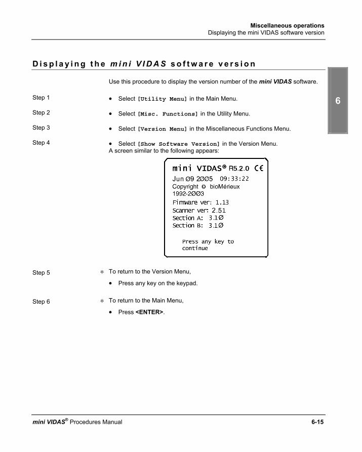
Miscellaneous operations Displaying the mini VIDAS software version
6
7
8
9
10
mini VIDAS® Procedures Manual 6-15
D i s p l a y i n g t h e m i n i V I D A S s o f t w a r e v e r s i o n
Use this procedure to display the version number of the mini VIDAS software. Step 1 • Select [Utility Menu] in the Main Menu. Step 2 • Select [Misc. Functions] in the Utility Menu. Step 3 • Select [Version Menu] in the Miscellaneous Functions Menu. Step 4 • Select [Show Software Version] in the Version Menu.
A screen similar to the following appears:
Step 5 ∗ To return to the Version Menu,
• Press any key on the keypad. Step 6 ∗ To return to the Main Menu,
• Press <ENTER>.

Miscellaneous operations Printing the mini VIDAS software version
6-16 mini VIDAS® Procedures Manual
P r i n t i n g t h e m i n i V I D A S s o f t w a r e v e r s i o n
Use this procedure to print the version number of the mini VIDAS software.
Step 1 • Select [Utility Menu] in the Main Menu.
Step 2 • Select [Misc. Functions] in the Utility Menu.
Step 3 • Select [Version Menu] in the Miscellaneous Functions Menu.
Step 4 • Select [Print Software Version] in the Version Menu. The Software version begins to print and the display returns to the Version Menu.
Step 5 • Press the <ENTER> key to return to the Main Menu.

Miscellaneous operations Displaying the assay version
6
7
8
9
10
mini VIDAS® Procedures Manual 6-17
D i s p l a y i n g t h e a s s a y v e r s i o n
Use this procedure to display the Assay version for the selected assay.
Step 1 • Select [Utility Menu] in the Main Menu.
Step 2 • Select [Misc. Functions] in the Utility Menu.
Step 3 • Select [Version Menu] in the Miscellaneous Functions Menu.
Step 4 • Select [Show Assay Version] in the Version Menu.
An assay selection list, similar to the following, appears:
Step 5 ∗ To display the assay version you want,
• Press the <↑> and <↓> keys. Step 6 • Select an assay.
A screen similar to the following appears:
Note: An intermediate screen appears for assays that have more than one version; the version
used is represented in the first two characters of the strip's bar code.

Miscellaneous operations Displaying the assay version
6-18 mini VIDAS® Procedures Manual
Step 7 ∗ To return to the assay selection list,
• Press any key.
Step 8 This step has two options:
∗ To return to the Version Menu,
• Press the <ENTER> key.
∗ To display additional assays,
• Go to step 5.

Miscellaneous operations Section counters
6
7
8
9
10
mini VIDAS® Procedures Manual 6-19
S e c t i o n c o u n t e r s
∗ In the Main Menu,
• Select [Misc. Functions] in the Utility Menu.
Then,
• Select [Section counters]. • Choose [Section A] or [Section B].
A screen appears showing the 2 counters [C1] and [C2].
[C1] : The number of job lists run in this section since the mini VIDAS was installed. [C2] : The number of job lists run in this section since the last reset performed by a bioMérieux technician. The date of the last reset is displayed on the screen.
IMPORTANT ! The reset operation can only be performed by bioMérieux technicians or a qualified person trained by bioMérieux.

Miscellaneous operations Printing the assay version
6-20 mini VIDAS® Procedures Manual
P r i n t i n g t h e a s s a y v e r s i o n
Use this procedure to print the list of assays and their respective versions. Step 1 • Select [Utility Menu] in the Main Menu. Step 2 • Select [Misc. Functions] in the Utility Menu. Step 3 • Select [Version Menu] in the Miscellaneous Functions Menu. Step 4 • Select [Print Assay Version] in the Version Menu.
The following message appears: Preparing report Please wait...
The assay list then begins to print and the display returns to the Version Menu. A portion of an assay list printout appears below.
Step 5 ∗ To return to the Main Menu,
• Press <ENTER>.

Miscellaneous operations Updating the mini VIDAS software via the memory card
6
7
8
9
10
mini VIDAS® Procedures Manual 6-21
U p d a t i n g t h e m i n i V I D A S s o f t w a r e v i a t h e m e m o r y c a r d
Use this procedure to install revised mini VIDAS software in the mini VIDAS. These updates are sent to you by bioMérieux on memory cards. An accompanying letter details the update.
Step 1 • Switch off the mini VIDAS. Step 2 • Place the memory card in the slot on the back of the instrument, in the
direction indicated by the arrow, with the label towards the outside. See the figure below for the location of the memory card slot.
Memory card slot
Fig. 6-6: mini VIDAS back panel
The memory card is placed in the slot with the end containing the two rows of connector holes inserted first.
• Apply gentle pressure on the center of the card to seat it. The ejection button, located below the slot, pops up when the card is properly seated. The card itself is keyed so that it cannot be seated improperly.
Step 3 • Switch on the mini VIDAS • Select [Utility Menu] in the Main Menu.
Step 4 • Select [Misc. Functions] in the Utility Menu.

Miscellaneous operations Updating the mini VIDAS software via the memory card
6-22 mini VIDAS® Procedures Manual
Step 5 • Select [Update] in the Miscellaneous Functions Menu.
The following screen appears:
Step 6 ∗ To begin the update,
• Select [Yes].
Note: Make sure that you have inserted the memory card into its slot. See Step 1. Once an update begins, it cannot be interrupted. The following messages appear:
Updating Please wait...
In approximately two minutes, a bar graph appears with the messages. As the update proceeds, the bar graph fills to indicate the progress of the update. About 30 seconds after the bar graph fills completely, the following messages appear:

Miscellaneous operations Updating the mini VIDAS software via the memory card
6
7
8
9
10
mini VIDAS® Procedures Manual 6-23
Step 7 ∗ To turn off the mini VIDAS,
• Reach behind the instrument and turn the power off. Step 8 • Push the ejection button below the memory card slot to unseat the card.
Remove the card from the slot. Step 9 • Turn the power back on after about 15 seconds.
The mini VIDAS goes through its power up sequence, ending with the appearance of the Main Menu. The mini VIDAS update is now complete.
Note: You can use the preceding "Displaying the mini VIDAS software version", to display the new version number.

Miscellaneous operations Verifying the memory card data
6-24 mini VIDAS® Procedures Manual
V e r i f y i n g t h e m e m o r y c a r d d a t a
Use this procedure to verify the data on the memory card that is installed in the memory card slot on the back of the mini VIDAS.
• Select [Card Info.] in the Utility Menu.
The following message appears: Scanning card Please wait...
∗ After the mini VIDAS reads the card, a screen similar to the following appears:
∗ To return to the Utility Menu,
• Press any key.

Miscellaneous operations Shipping the mini VIDAS
6
7
8
9
10
mini VIDAS® Procedures Manual 6-25
S h i p p i n g t h e m i n i V I D A S
CAUTION! The mini VIDAS blue weighs 40 kg (88 lb). The mini VIDAS weighs 37 kg (81.5 lb). Two people should lift it out of its box and place it on the benchtop.
CAUTION! The mini VIDAS blue should be lifted or moved using the gripping area
located on its base.
Use this procedure to prepare the mini VIDAS for shipment in its original shipping container.
∗ What you will need: The following are required for this procedure: − The original mini VIDAS shipping container. − The two foam end caps and bottom support for the instrument. − The antistatic bag for the instrument. − The two shipping blocks, one with a 28 centimeter-long (11 inches) wooden
dowel.
CAUTION! Follow this procedure very carefully to avoid causing any damage to the electrical components and the optical parts of the instrument which are extremely fragile.
Step 1 • Select [Utility Menu] in the Main Menu.
Step 2 • Select [Misc. Functions] in the Utility Menu.
Step 3 • Select [Park System] in the Miscellaneous Functions Menu.
The following prompt appears: Parking disables the instrument. Are you certain?
The prompt is accompanied by [Yes] and [No] selections.

Miscellaneous operations Shipping the mini VIDAS
6-26 mini VIDAS® Procedures Manual
Step 4 ∗ To park the mini VIDAS,
• Select [Yes].
Note: From this point, the parking process cannot be interrupted. The following things occur: − You hear the scan head moving inside the instrument. It is being placed in
its parking position. − You hear other motors working as other parts of the mini VIDAS are placed
in their parking positions. − The two reagent strip trays are retracted fully into the instrument. When the mini VIDAS is fully parked, the status lights on each section blink.
Step 5 ∗ To turn off the mini VIDAS,
• Reach behind the instrument and turn the power off. You can also remove the AC power cord at this time.
Step 6 • Open the dust cover of section A.
• Take the shipping block with the wooden dowel and place it in section A. The orientation of the shipping block is such that the portion of the block with the dowel is on top. The block is inserted dowel first, so that the dowel goes into reagent strip position 3 (A3).
• Push the shipping block completely into the section so that it occupies the space previously taken by the reagent strip tray.
Step 7 • Open the dust cover of section B.
• Place the other shipping block (the one without the dowel) completely into the section so that it occupies the space previously taken by the reagent strip tray.
Step 8 • Close the reagent tray dust covers and secure them with a piece of
adhesive tape. Step 9 • Remove the paper roll from the printer. Replace the spindle in its slots and
secure it with adhesive tape. • Close the printer door.
Step 10 • Carefully lift one end of the mini VIDAS and,
• Place the antistatic bag over the elevated end of the instrument. Step 11 • Repeat step 10 at the other end of the instrument.

Miscellaneous operations Shipping the mini VIDAS
6
7
8
9
10
mini VIDAS® Procedures Manual 6-27
Step 12 • Place the foam end caps on each end of the instrument.
Note: The end caps are not interchangeable. Step 13 • Insert the bottom support (a piece of cardboard with two foam blocks
attached) into the bottom of the shipping box. The foam blocks should be face up.
Step 14 • Lift the mini VIDAS and place it in the shipping container so the channel
formed by the two metal strips in the center of the instrument fits between the two foam end caps.
Step 15 • Close the box and secure it with appropriate adhesive tape.


mini VIDAS® Procedures Manual 7-1
7 Error handl ing
I n t r o d u c t i o n
The mini VIDAS has several ways to inform you that there is a problem in the instrument. This chapter shows you how the mini VIDAS alerts you to a problem, the various error messages you may see, and, in some cases, what you can do to correct the error condition. The following procedures are described in this chapter:
♦ The error message alert system ................................................................ 7-2 ♦ Start errors................................................................................................. 7-4 ♦ Instrument errors...................................................................................... 7-13 ♦ Problems that may occur with the bar code reader.................................. 7-22 ♦ Assay report errors .................................................................................. 7-23 ♦ Printer errors ............................................................................................ 7-25 ♦ Viewing saved errors ............................................................................... 7-26 ♦ Displaying instrument temperatures......................................................... 7-27 ♦ Printing instrument temperatures ............................................................. 7-28

Error handling The error message alert system
7-2 mini VIDAS® Procedures Manual
T h e e r r o r m e s s a g e a l e r t s y s t e m
The mini VIDAS has a system for alerting you to the presence of an error. There is an audio cue (a beep) and an optional video cue (the display blinks). Both the audio and visual cues are controlled by configuration options: − Error beep.
You can set the volume of the beep the mini VIDAS emits when there is an error. There are configuration options to set an initial volume and a final volume.
The initial volume is the volume used when the beep begins.
The volume then increases until you respond, or until it reaches the final volume. Both volumes can be set to the same level so that there is no increase in loudness.
− Display blink.
There is a configuration option in which you can enable or disable a display blink to accompany the error beep.
See chapter 6 for procedures to set these configuration options.
Responding to an error alert
∗ When the mini VIDAS alerts you to the presence of an error condition,
• Press the <?> key to respond. This action terminates the error beep and, if enabled, the display stops blinking. Whatever was being displayed when you pressed the <?> key is replaced by an error message screen. The format of the message screen depends on the type of error.

Error handling The error message alert system
6
7
8
9
10
mini VIDAS® Procedures Manual 7-3
Types of error message screens There are two basic types of error message screens. − One type is used when there is a start error. A start error occurs during the
initial processing of a run of reagent strips.
− The other type of error message screen is used for all other types of messages. It consists of an error code number and the error message itself.
∗ In the sections that follow, all the types of errors and error screens are described in detail.

Error handling Start errors
7-4 mini VIDAS® Procedures Manual
S t a r t e r r o r s
A start error can occur when you start a section. The mini VIDAS goes through a series of preprocessing steps that include reading the bar code on the label of each reagent strip, and performing an optical check of the substrate.
What happens?
∗ When a start error occurs, the mini VIDAS displays an error message screen. Depending on the selections you made in the Configuration Menu:
− The mini VIDAS beeps. (see section "Setting initial error volume" chapter 3 page 3-27).
− The display blinks. (see section "Enabling display blinking" chapter 3 page 3-29).
− The error message is printed. (see chapter 3 page 3-31).
Start errors cause the mini VIDAS to halt the run in the section containing the error. The other section is not affected by any of this action.

Error handling Start errors
6
7
8
9
10
mini VIDAS® Procedures Manual 7-5
What you should do
∗ To display the error message screen,
• Press the <?> key. (This action also stops the error beep).
The figure below is an example of a possible error message screen for a start error. The screen displays the status of each position within the section having the error.
Notice that, for all of the positions except B4, the status is shown by “Okay.” These positions have no errors. Position B4, however, shows a status of:
TXG Bad barcode This message indicates the start error.

Error handling Start errors
7-6 mini VIDAS® Procedures Manual
The start error messages are:
Bad Barcode The mini VIDAS was unable to read the bar code on the reagent strip.
Expired lot The reagent lot has expired.
Incompatible The assay in this position is not compatible with other assays in the section. This type of error should only occur in a Load and Go run. In a defined run, the mini VIDAS would detect incompatible assays before they were run.
Misaligned A dual reagent strip has been placed in the wrong positions. This type of error should only occur in a Load and Go run. In a defined run, the mini VIDAS would detect a misaligned dual reagent strip.
Sub.(XX) The initial substrate fluorescence reading is not acceptable. Note: XX corresponds to the fluorescence value read.
Wrong type The type of assay specificed for this position is different to the one found by the mini VIDAS. This type of error should only occur in a defined run.
No strip An assay was specified for this position but no reagent strip was found. This type of error should only occur in a defined run.
Okay There is no error in this position.
Unknown Assay There is no protocol stored in the mini VIDAS for the assay type. This type of error should only occur in a Load and Go run or in a defined run if the assay (assay code) has not been selected (optional).
Not Empty The position is supposed to be empty, yet a test is detected.
Missing ID The sample ID, required for configuration of the LIS, is missing.
Wrong Control Wrong Std
The number of the control or standard has been entered for a parameter whereas it does not exist in the PTC base.
No Standard There is no calibration in the mini VIDAS and no calibrators in the job list.
Old Standard The calibration for this assay lot has expired.

Error handling Start errors
6
7
8
9
10
mini VIDAS® Procedures Manual 7-7
How to resolve start errors
In the previous subsection, you saw that by pressing the <?> key, you access the error message screen. This screen tells you the type of start error in the section. There are two general categories of responses, depending on the type of error. For all start errors except a bad bar code error, you can atttempt to resolve the condition by manipulating the reagent strip in some way. Details are given in the following subsection, Remedies for start errors.
∗ For a bad bar code error, you must enter the bar code manually. The procedure for manual bar code entry follows the remedies for the other start errors.
Remedies for start errors (except bad bar code)
Step 1 • Perform the following procedure, depending on the type of error.
Sub.(XX) • Make sure the optical cuvette on the reagent strip is clean. • Replace the reagent strip.
Incompatible • Run the reagent strip in the other section or in a different run. • Check for assay compatibility (see page 4-9 of chapter 4).
Misaligned (Applies to dual reagent strips). • Move the strip so that it occupies an acceptable pair of positions: 1 & 2,
3 & 4, 5 & 6.
No strip • Place a reagent strip in the appropriate position or delete the entry for that position.
Unknown assay • Remove the reagent strip.
Wrong type • Put the reagent strips in their proper positions or correct the test entries.
No Master Lot The MLE card (Master Lot data) was not entered.
Missing ID • Stop and return to the section status screen to enter an ID for the position.

Error handling Start errors
7-8 mini VIDAS® Procedures Manual
Step 2 • Press <Previous Screen> from the error message screen.
The following selections are displayed: [Restart]
[Cancel]
Step 3 This step has two options:
• Select [Cancel] to abort the run. The mini VIDAS returns to the state it was in before the run was started. Any data you entered about the assays are retained.
• Select [Restart] to restart the run. The run resets and begins with another bar code read and substrate check.

Error handling Start errors
6
7
8
9
10
mini VIDAS® Procedures Manual 7-9
Manual ly entering bar codes This procedure begins from the error message screen display.
Step 1 • Press the <Number Key> corresponding to the position containing the bar code error.
The manual bar code entry screen appears:
Step 2 • Remove the reagent strip from the section and find the eight-digit alphanumeric bar code, located next to the assay code.
Note: See "The label" on page 2-25 of chapter 2.
Step 3 • Manually enter the bar code as follows:
∗ For a digit • Press the appropriate <Number Key>.
∗ For a letter, • Press the <↑>, <↓>, <←> and <→> keys to highlight the appropriate
character in the character box. • Select the [character box].
It appears in the cursor box. Use these functions as needed: [Clr] to clear the cursor box. [←] to delete one character in front of the cursor.
Note: "O" and "I" are letters. "Ø" and "1" are the digits zero and one.

Error handling Start errors
7-10 mini VIDAS® Procedures Manual
Step 4 ∗ When the bar code entry has been completed,
• Press <Previous Screen>. The mini VIDAS checks the bar code you entered. If the bar code is valid, the display returns to the Error message screen. • Go to Step 6. If the bar code is not valid, the following message appears:
Warning: Barcode still invalid Press any key to continue
• Go to Step 5. Step 5 • Press any key on the keypad.
The display returns to the error message screen. If you want to reenter the bar code, go to step 1.
Step 6 • Press <Previous Screen>.
The following selections appear: [Restart] [Cancel]
Step 7 This step has two options:
∗ To abort the run,
• Select [Cancel]. The mini VIDAS returns to the state it was in before the run was started. Any data you entered about the assays are retained.
∗ To restart the run,
• Select [Restart]. The run resets and begins with another bar code read and substrate check.

Error handling Start errors
6
7
8
9
10
mini VIDAS® Procedures Manual 7-11
Substrate error
This means that the substrate value exceeds the acceptable values for the assay. Change the reagent strip and start again.
Expired lot error
The kit reagents you are using have expired. Use a new lot of reagents.
∗ If you run the assay, a message will appear on your result sheet indicating that the assay was performed using an expired lot.
Error handling Start errors
7-12 mini VIDAS® Procedures Manual
Other error messages When the mini VIDAS detects a System error, an error message screen is displayed. Depending on the selections you made in the Configuration Menu:
− The mini VIDAS beeps. (see section "Setting initial error volume" chapter 3 page 3-27).
− The display blinks. (see section " Enabling display blinking" chapter 3 page 3-29).
− The error message is printed. (see chapter 3 page 3-31).
System errors cause the mini VIDAS to halt the run in the section containing the error. The other section is not affected by any of this action. These error alert cues continue until you respond to the error condition by pressing the <?> key. This action causes the mini VIDAS to display an error message screen. The text on the screen is similar to the following:
Errorcode: 73 Time: 14:53:20 14/09/Ø2 MLE Card data bad

Error handling Instrument errors
6
7
8
9
10
mini VIDAS® Procedures Manual 7-13
I n s t r u m e n t e r r o r s
Instrument errors comprise a broad range of error conditions. An error message display consists of three lines:
Line 1 : Errorcode: 73
This line contains a number that corresponds to the specific error. Make note of this number in case you need to contact the bioMérieux® Technical Assistance. The mini VIDAS maintains a log of the last ten error messages produced by the mini VIDAS. They are saved unless mini VIDAS power is shut off. You can access stored error messages via the View Saved Errors function. See the section "Viewing saved errors" on page 7-26 of this chapter.
Line 2 : Time: 14:53:20 14/09/Ø2 This line contains the time and date that the error message was produced.
Line 3 : MLE Card data bad This line contains the actual error message text. These messages are detailed on the next page.

Error handling Instrument errors
7-14 mini VIDAS® Procedures Manual
Error messages Listed below are all of the error messages programmed into the mini VIDAS.
∗ If error messages other than the ones below appear, call bioMérieux Technical Assistance.
∗ In some cases, there are suggestions for corrective action. Where no corrective action is possible, or if the corrective actions fail, the final action is to call bioMérieux Technical Assistance. Warning - LIS Validation Queue Full
The validation queue is a temporary storage area for results waiting to be validated. This message appears if the results of 8 sections are already stored in the validation queue and a 9th section is run. Use the results validation procedure to remove results from this queue. Warning LIS upload queue full
This message indicates a possible problem in the mini VIDAS to LIS interface. See the message “Unable to complete LIS upload of results.” Some scanner errors lost due to overflow
This message may occur after repeated scanner errors. Call bioMérieux Technical Assistance to report this message. Some section errors lost due to overflow
This message may occur after repeated section errors. Call bioMérieux Technical Assistance to report this message. Optics autocalibration data corrupt - instrument may be out of calibration
Call bioMérieux Technical Assistance. Configuration data not found
This error would occur during the power-on startup sequence. Note that any previously entered configuration options are lost, and the options have returned to their default states. Enter one or two configuration changes. Repeat the power up start sequence. If the error recurs, call bioMérieux Technical Assistance.

Error handling Instrument errors
6
7
8
9
10
mini VIDAS® Procedures Manual 7-15
MLE Card data bad The instrument failed to read a Master Lot Data card. Inspect the card for proper placement in the reagent strip tray, debris, or smudges. Replace or reinsert, as necessary. Retry the read operation, or enter the data manually. If the error recurs, call bioMérieux Technical Assistance. Assay data load failed
The mini VIDAS cannot read the protocol memory card. Make sure the protocol memory card is in the memory card slot. Reinsert the memory card to ensure proper contact. Retry the last operation. If the error recurs, call bioMérieux Technical Assistance. Normal Range save failed
Call bioMérieux Technical Assistance. Normal Range load failed Call bioMérieux Technical Assistance. Assay startup error
This error would appear during the preprocessing steps of a run. Perform the procedure to halt the section. Retry an assay in the same Section. If the error recurs, call bioMérieux Technical Assistance. Section reset failed
Check the section for physical obstructions or any jams. Perform the halt operation on the section. If the error recurs, call bioMérieux Technical Assistance.
Error handling Instrument errors
7-16 mini VIDAS® Procedures Manual
Standard save failed
Call bioMérieux Technical Assistance.
Assay failed
The assays in a section have failed to process correctly. Retry an assay in the same section. If the error recurs, call bioMérieux Technical Assistance.
Assay processing error
The assays in a section have failed to process correctly. Retry an assay in the same section. If the error recurs, call bioMérieux Technical Assistance.
Communications error
Retry the operation that created the error. If the error recurs, call bioMérieux Technical Assistance.
Section communications error
Halt the Section with the error. Retry an assay in the same section. If the error recurs, place the Section offline and call bioMérieux Technical Assistance.
Unknown section error
Call bioMérieux Technical Assistance.
Unknown software error
Call bioMérieux Technical Assistance.
Unknown scanner error
Call bioMérieux Technical Assistance.
External printer error
The external printer has sent an error signal to the mini VIDAS. Consult your printer manual.

Error handling Instrument errors
6
7
8
9
10
mini VIDAS® Procedures Manual 7-17
Internal printer error
Retry a print operation. If the error recurs, call bioMérieux Technical Assistance. Cannot begin bar code read - check door
Check to see that the door to the SPR® block is completely closed and restart the assay. If the error recurs, call bioMérieux Technical Assistance. Cannot begin assay - check door
Check to see that the door to the SPR block is completely closed and restart the assay. If the error recurs, call bioMérieux Technical Assistance. Unable to initialize Section
This error would occur during the power-on startup sequence. Turn power to the instrument off. Check the instrument for physical obstructions or other possible jams. Perform the power-on startup sequence again. If the error recurs, call bioMérieux Technical Assistance. External printer offline
The external printer has sent an offline signal to the mini VIDAS. Press the online button on the printer, or consult your printer manual. Instrument has been too busy for autocalibration to occur
Allow the mini VIDAS to sit idle (not performing assays) for at least two hours. Continue normal operations. If the error recurs, call bioMérieux Technical Assistance.

Error handling Instrument errors
7-18 mini VIDAS® Procedures Manual
New LIS Results have been discarded due to full queues
This message appears after other messages warning you that the LIS result validation or upload queues are full. To resolve this situation, you must use the result validation and upload procedures to reduce the number of results in those queues. Boot EPROM obsolete
This error would appear during the power-on startup sequence. Turn the mini VIDAS power off and then on again to restart the mini VIDAS. If the error recurs, call bioMérieux Technical Assistance. Scanner board memory almost full
Call bioMérieux Technical Assistance to report this message. Scan head motor movement becoming restricted
Turn the instrument power off. Remove the lower front cover and look inside for any physical obstructions that could cause a jam. Call bioMérieux Technical Assistance to report this message. Scanner Board failure
Turn power to the instrument off. Perform the power-on startup sequence. If the error recurs, call bioMérieux Technical Assistance. Temperature monitoring failed
Allow any assays that are running to complete. Turn the power to the instrument off. Perform the power-on startup sequence. If the error recurs, call bioMérieux Technical Assistance. Section hardware failure
Turn power to the instrument off. Perform the power-on startup sequence. If the error recurs, halt the section, place it offline, and then call bioMérieux Technical Assistance.

Error handling Instrument errors
6
7
8
9
10
mini VIDAS® Procedures Manual 7-19
Scan head motor failure
Turn the instrument power off. Remove the lower front cover and look inside for any physical obstructions that could cause a jam. Retry the operation. If the error recurs, call bioMérieux Technical Assistance. Software failure
Call bioMérieux Technical Assistance. Tray mechanism failure
Check the reagent strip tray area for any physical obstructions that could cause a jam. Also check the tray to see that it is on its track. This is especially important after decontaminating the instrument. Run a TP6 assay. If the error recurs, call bioMérieux Technical Assistance. Pump mechanism failure
Check the area inside the SPR block for any physical obstructions that could cause a jam. Run a TP4 assay. If the error recurs, call bioMérieux Technical Assistance. Tower mechanism failure
Check the area inside the SPR block for any physical obstructions that could cause a jam. Run a TP5 assay. If the error recurs, call bioMérieux Technical Assistance. Hardware failure
Turn power to the mini VIDAS off. Perform the power-on startup sequence. Retry another assay. If the error recurs, call bioMérieux Technical Assistance. Optical hardware failure (or excessive auto-calibration drift) Turn power to the instrument off. Perform the power-on startup sequence. If the error recurs, call bioMérieux Technical Assistance.

Error handling Instrument errors
7-20 mini VIDAS® Procedures Manual
No Master Lots available The mini VIDAS cannot read the protocol memory card. Make sure the protocol memory card is in the memory card slot. Reinsert the memory card to ensure proper contact. Retry the last operation. If the error recurs, call bioMérieux Technical Assistance. External printer paper empty
The external printer has sent a signal to the mini VIDAS indicating it is out of paper. Reload the printer with paper. If the printer still has paper, check the cable connections between the printer and the mini VIDAS. Consult your printer manual if necessary. Internal printer paper empty
Install another roll of paper in the thermal printer. Attempt another print operation. If the error recurs, call bioMérieux Technical Assistance. Restoring saved master lot information Try to reenter the Master Lot data. If the error recurs, call bioMérieux Technical Assistance. SPR temperature out of allowed range
Check the temperature of the SPR block. If the temperature is low, make sure all doors on the mini VIDAS are closed. Allow time for the temperature to equilibrate. If the error continues, call bioMérieux Technical Assistance.

Error handling Instrument errors
6
7
8
9
10
mini VIDAS® Procedures Manual 7-21
Tray temperature out of allowed range
Check the temperature of the reagent strip tray. If the temperature is low, make sure all doors on the mini VIDAS are closed. Allow time for the temperature to equilibrate. If the error continues, call bioMérieux Technical Assistance. Unable to complete LIS upload of results
The mini VIDAS was unable to transfer its results. First check all cable connections between the mini VIDAS and the LIS computer. Also, make sure that your LIS computer is ready to receive data.

Error handling Problems that may occur with the bar code reader
7-22 mini VIDAS® Procedures Manual
P r o b l e m s t h a t m a y o c c u r w i t h t h e b a r c o d e r e a d e r
The reader does not emit a beam of light
• Check that the cable is securely connected (see the bar code reader installation procedure).
• Check that the trigger is working. After verification, if the reader does not function properly: • Repeat the bar code reader installation procedure.
• If the problem persists, call bioMérieux Technical Assistance or your local bioMérieux representative.
Reader fails to read bar codes
There are several possibilities:
∗ The bar codes are unreadable: IMPORTANT ! To be readable, bar codes must be complete, unstained, and untorn.
• If the configuration sheet provided with the reader is missing or unreadable, call bioMérieux Technical Assistance or your local bioMérieux representative.
∗ The reader window is not clean:
• Check that the reader window is clean and if necessary clean it using a soft cloth.
• Repeat the reading.
∗ The reading distance is incorrect:
• Slowly move the reader away from and/or towards the bar code until the optimal position for reading has been reached.
Note: A beep indicates that reading has been performed.

Error handling Assay report errors
6
7
8
9
10
mini VIDAS® Procedures Manual 7-23
A s s a y r e p o r t e r r o r s
Errors related directly to results on an assay report are not displayed on an error screen. Rather, the assay report itself is used to report these errors. The assay report uses a set of symbols to mark the part of the report that contains the error. A footnote then appears at the bottom of the report, referencing the same symbol. The footnote includes the error message.
Correct ing assay report errors In all cases, the test should be repeated. If the error recurs and you suspect a problem in the mini VIDAS, call bioMérieux Technical Assistance.
Assay report error symbols Following are the symbols used on assay reports and their corresponding error messages:
& "Low reading."
A fluorescence reading for the reagent strip is below a preset limit.
§ "High reading." A fluorescence reading for the reagent strip is above a preset limit
¥ "Offscale reading."
A fluorescence reading for the reagent strip is outside the operating range of the detector.
# "Low RFV."
An RFV for the reagent strip is below a preset limit.
! "High RFV." An RFV for the reagent strip is above a preset limit.
{ "No reading."
Call bioMérieux Technical Assistance.
¬ "Math Error." The mini VIDAS encountered a calculation error, e.g., a divide by zero.

Error handling Assay report errors
7-24 mini VIDAS® Procedures Manual
@ "High Test Value."
A test value calculated for the reagent strip is above a preset limit.
"Low Test Value." A test value calculated for the reagent strip is below a preset limit.
¢ "Sample Over-Diluted."
~ "Low control."
A high control is giving a low response.
¶ "High control." A low control is giving a high response.
$ "Std. CV exceeded."
The coefficient of variation (CV) for the standard result is greater than a preset limit.
£ "Invalid std."
The result for the standard is invalid and cannot be used to calculate the result for the test samples.
] "Please refer to the package insert"
Error messages on assay reports
∗ If a standard is out-of-range or missing (when an assay is started), the following error message is printed at the bottom of the assay report:
Insufficient standard run or Standard value out of range
The test result should not be taken into account, and it is recommended to repeat calibration for the test.

Error handling Printer errors
6
7
8
9
10
mini VIDAS® Procedures Manual 7-25
P r i n t e r e r r o r s
If the internal printer is out of paper or does not respond, the mini VIDAS will keep retrying for 30 seconds and then sound the error beep. Use this procedure to resolve printer errors.
Step 1 ∗ To display the error message screen.
• Press the <?> key. The error message refers to the internal printer.
Step 2 • Replace the printer paper if the error indicates that the printer is out of
paper. Step 3 The following selections are displayed:
[Retry Printing]
[Abort Printing]
Step 4 This step has two options:
∗ To tell the printer to stop trying to print at this time, • Select [Abort Printing]. The mini VIDAS will try to print this job again if: − the printer is told to print something else, − you use the Select Printer function on the configuration menu.
∗ To try to print the job at this time, • Select [Retry Printing].

Error handling Viewing saved errors
7-26 mini VIDAS® Procedures Manual
V i e w i n g s a v e d e r r o r s
The mini VIDAS stores the last ten error messages it creates. These messages remain in the mini VIDAS unless the power is turned off. Use the following procedure to access the stored error messages.
Step 1 • Select [Utility Menu] in the Main Menu. Step 2 • Select [View Saved Errors] in the Utility Menu.
The screen displays an error message similar to the following: Errorcode: 73 (Saved) Time: 14:53 09/14/Ø2 MLE Card data bad
Note: The first message shown is the newest message stored in the message file. Step 3 This step has two options:
∗ Press the <ENTER> key to display the next message.
∗ Press the <Previous Screen> key to return to the Utility Menu.

Error handling Displaying instrument temperatures
6
7
8
9
10
mini VIDAS® Procedures Manual 7-27
D i s p l a y i n g i n s t r u m e n t t e m p e r a t u r e s
Use this procedure to display the temperature readings for the SPR block and the reagent strip tray.
Step 1 • Select [Status Screen] in the Main Menu. Step 2 • Select [Display temperatures].
A screen similar to the following appears:
Step 3 ∗ To return to the Main Menu,
• Press the <Previous Screen> key twice.

Error handling Printing instrument temperatures
7-28 mini VIDAS® Procedures Manual
P r i n t i n g i n s t r u m e n t t e m p e r a t u r e s
Use this procedure to print a copy of the temperature readings for the SPR block and the reagent strip tray.
Step 1 • Select [Status Screen] in the Main Menu. Step 2 • Select [Display temperatures].
A screen similar to the following appears:
Step 3 • Select [Print].
The temperature begins to print and the screen returns to the Main Menu. Step 4 ∗ To return to the Main Menu,
• Press the <Print Screen> key twice. Nota: Wait until the result sheet finishes printing (if one is in progress) before printing the
temperature report.

mini VIDAS® Procedures Manual 8-1
8 Appendices
I n t r o d u c t i o n The following appendices are presented in this chapter: Appendix A: Specifications ♦ Characteristics ........................................................................................... 8-3 Appendix B: Maintenance ♦ Preventive maintenance .......................................................................... 8-10 ♦ User maintenance.................................................................................... 8-11 ♦ Decontamination of the mini VIDAS blue ................................................. 8-13 ♦ Decontamination of the mini VIDAS......................................................... 8-21 ♦ Using the quality control test .................................................................... 8-27 ♦ Cleaning the computer screen and keypad.............................................. 8-27 ♦ Cleaning the bar code reader .................................................................. 8-27 Appendix C: Quality control ♦ Checking performance............................................................................. 8-29 ♦ Auto-calibration of the optical system ...................................................... 8-31 ♦ Pipetting for the mini VIDAS .................................................................... 8-33 ♦ Temperature validation for the mini VIDAS .............................................. 8-34 ♦ mini VIDAS master curve establishment and calibration.......................... 8-35 Appendix D: Installing optional external hardware ♦ External printer......................................................................................... 8-39 ♦ Testing the external printer ...................................................................... 8-40 ♦ Installing the bar code reader .................................................................. 8-41 Appendix E: Computer interface information ♦ Introduction .............................................................................................. 8-45 ♦ Configuration information......................................................................... 8-48 ♦ Example of a mini VIDAS upload ............................................................. 8-50


mini VIDAS® Procedures Manual 8-3
Appendix A: Speci f icat ions C h a r a c t e r i s t i c s Environmental requirements
− Operating Temperature: + 15° C to + 30° C (59° F to 86° F)
− Storage Temperature: - 10° C to + 40° C (14° F to 104° F)
− Relative Humidity: 10 to 80%, non-condensing − Type of Installation: for indoor use only; light industrial equipment − Installation Category (overvoltage category): II
(according to IEC 1010.1) − Degree of Pollution: n°2
(according to IEC 1010.1) − Maximum installation altitude: 2,000 m
Physical features
Dimensions mini VIDAS blue mini VIDAS instrument packed instrument alone instrument packed instrument alone
Height: 59 cm (23 inches) 45 cm (17.7 inches) 57 cm (22¼ inches) 44 cm (17¼ inches)
Width: 80 cm (31.4 inches) 57.5 cm (22.6 inches) 68 cm (26½ inches) 54 cm (21¼ inches)
Depth: 66 cm (26 inches) 55 cm (21½ inches) 68 cm (26½ inches) 53 cm (21¼ inches)
Physical space requirements mini VIDAS blue mini VIDAS Height: 65 cm (25½ inches) 65 cm (25½ inches)
Width: 120 cm (47 inches) 120 cm (47 inches)
Depth: 90 cm (35½ inches) 90 cm (35½ inches)
The instrument must be placed on a flat surface with a maximum horizontality defect of 5°.
Sound level Sound level : < 59 dBA
Mass mini VIDAS blue mini VIDAS instrument packed instrument alone instrument packed instrument alone
Mass: 47 kg (103.6 lb) 40 kg (88 lb) 46 kg (101.4 lb) 37 kg (81.5 lb)

Appendix A: Specifications Characteristics
8-4 mini VIDAS® Procedures Manual
Electrical requirements
Class 1 Instrument
The instrument includes an internal bar code reader with a 660 nm LED whose radiation is Class 1 according to IEC 60825-1. This class does not present a risk.
mini VIDAS blue mini VIDAS
Voltage 100 - 240 VAC 3 – 1.2 A
100 - 120 VAC 200 - 240 VAC
The voltage (100 - 120 VAC or 200 - 240 VAC) is selected using the power unit at the back of the instrument.
Consumption 100 - 240 VAC 1.5 – 0.8 A
1.5 A at 100 - 120 VAC 0.8 A at 200 - 240 VAC
Frequency 50 - 60 Hz 50 - 60 Hz
Power 150 Watts 180 Watts (maximum) 75 Watts (nominal)
Fuse current External: 4.0 AT
External (power input module): 1.5 AT at 100 - 120 VAC 1.6 AT at 200 - 240 VAC
Approximate Emission of Heat
512 Btu / hr 150 W 250 Btu / hr 75 W
Power switch Location: back of instrument Type: bipolar (phase + neutral) Max. leakage of current: < 1mA

Appendix A: Specifications Characteristics
6
7
8
9
10
mini VIDAS® Procedures Manual 8-5
CAUTION! The user must comply with the technical specifications and standards in this manual to ensure user safety as well as the proper functioning of the mini VIDAS. bioMérieux SA is in no case liable for any damage that may arise from failure to comply with these specifications or any operation conducted on the equipment not in compliance with these mandatory standards. Moreover, the warranty for this equipment is expressly subject to use of the mini VIDAS in compliance with the procedures and specifications herein.

Appendix A: Specifications Characteristics
8-6 mini VIDAS® Procedures Manual
Technical features
Capacity − 12 test positions: 2 sections with 6 positions in each section.
− Up to 30 tests/hour depending on the type of assay used (see test duration in the package insert for each mini VIDAS assay).
Motors − Automatic control by stepper motors.
Pumping − 2 pumps; one for each section
− Mixing, diluting, and transferring of liquids
Temperature control
Absolute Accuracy SPR: 36°C – 38°C Tray: 35°C – 38°C
Relative Accuracy SPR: ± 0.7°C between the 2 sections
Tray: ± 1°C between the 2 sections
Process Thermal resistance
Automatic Control by thermal probe
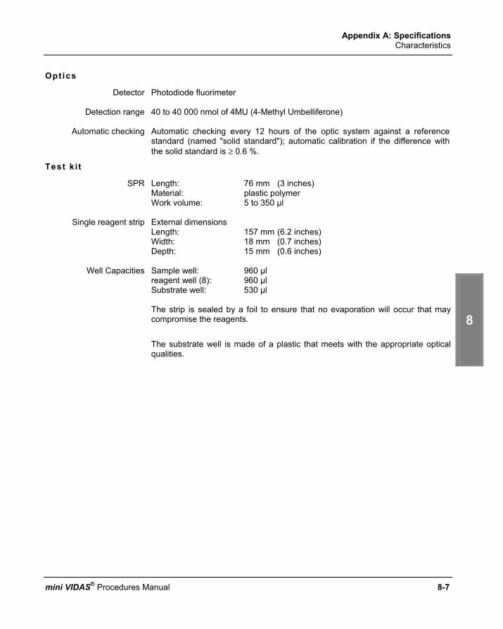
Appendix A: Specifications Characteristics
6
7
8
9
10
mini VIDAS® Procedures Manual 8-7
Optics
Detector Photodiode fluorimeter
Detection range 40 to 40 000 nmol of 4MU (4-Methyl Umbelliferone)
Automatic checking Automatic checking every 12 hours of the optic system against a reference standard (named "solid standard"); automatic calibration if the difference with the solid standard is ≥ 0.6 %.
Test ki t
SPR Length: 76 mm (3 inches) Material: plastic polymer Work volume: 5 to 350 µl
Single reagent strip External dimensions
Length: 157 mm (6.2 inches) Width: 18 mm (0.7 inches) Depth: 15 mm (0.6 inches)
Well Capacities Sample well: 960 µl
reagent well (8): 960 µl Substrate well: 530 µl
The strip is sealed by a foil to ensure that no evaporation will occur that may compromise the reagents. The substrate well is made of a plastic that meets with the appropriate optical qualities.


mini VIDAS® Procedures Manual 8-9
Appendix B: Maintenance
I n t r o d u c t i o n
This chapter deals with: − the preventive maintenance operations performed by bioMérieux
technicians or a qualified person trained by bioMérieux, − the routine maintenance operations which should be performed by the
user. The following topics are covered in this chapter: ♦ Preventive maintenance .......................................................................... 8-10 ♦ User maintenance.................................................................................... 8-11 ♦ Decontamination of the mini VIDAS blue ................................................. 8-13 ♦ Decontamination of the mini VIDAS......................................................... 8-21 ♦ Using the quality control test .................................................................... 8-27 ♦ Cleaning the computer screen and keypad.............................................. 8-27 ♦ Cleaning the bar code reader .................................................................. 8-27

Appendix B: Maintenance Preventive maintenance
8-10 mini VIDAS® Procedures Manual
P r e v e n t i v e m a i n t e n a n c e
Optimum performance of the mini VIDAS (within the limits of bioMérieux specifications) depends on the preventive maintenance being performed by bioMérieux technicians or a qualified person trained by bioMérieux only, as part of a maintenance contract. The list of maintenance operations and their frequency is available from bioMérieux.
IMPORTANT! As well as the user maintenance operations described in this manual, periodic preventive maintenance must be performed by bioMérieux.

Appendix B: Maintenance User maintenance
6
7
8
9
10
mini VIDAS® Procedures Manual 8-11
U s e r m a i n t e n a n c e
DANGER! Any break in the grounding protective conductor inside or outside the equipment or disconnection of the protective ground terminal may render the equipment dangerous. Deliberate interruption of such conductors is forbidden. After opening, if it is imperative to switch the instrument on, any adjustment, servicing or repair should be performed by a qualified technician, well aware of the possible risks. During a storm, never connect cables to the keyboards, screens, printer or telephones, or lightning conductors to the transmission lines.
Tools required for maintenance
No specific tools are required for preventive maintenance of mini VIDAS.
∗ The basic equipment and products required are: − sponges (Part no. 99 087) − a flat screw-driver,
− a screwdriver for recessed head screws, (only concerns mini VIDAS blue),
− disposable powderless gloves (latex type), − Dacron® swabs (Part no. 30 531), − demineralized water, − a bleach solution containing 0.5-0.6% active chlorine (5.5 to 6.6 g/l sodium
hypochlorite). This solution should be prepared in demineralized water. − curved forceps, − normal laboratory detergent solutions (7X®, AlconoxTM, LiquinoxTM or
equivalent) used according to the manufacturers recommendations.

Appendix B: Maintenance User maintenance
8-12 mini VIDAS® Procedures Manual
Summary of user maintenance operat ions
Frequency
Instrument
WEEKLY (W)
MONTHLY (M)
AS REQUIRED (B)
ANALYZER
• Cleaning of:
− SPR block.
• Decontamination of: − strip preparation trays
(for mini VIDAS blue) − reagent strip trays, − plastic trays.
• Checking of pipette mechanisms using the bioMérieux SA quality control test .
• Decontamination of: − strip preparation trays
(for mini VIDAS blue) − reagent strip trays, − plastic trays.
(in the event of accidental contamination)
• Cleaning of: − the screen, − the keypad.
Bar code reader
• Clean the window.
Note: To check the pipette mechanisms, follow the instructions in the reagent package insert.
To analyze the results, refer to the card included in the reagent kit which indicates the acceptable ranges for each lot.
IMPORTANT! All the panels of the instrument should be cleaned regularly using a weak detergent diluted in water. Do not use hot water (maximum temperature: 60°C) to clean the instrument bodywork and removable parts (e.g. plastic trays, strip preparation tray).

Appendix B: Maintenance Decontamination of the mini VIDAS blue
6
7
8
9
10
mini VIDAS® Procedures Manual 8-13
D e c o n t a m i n a t i o n o f t h e m i n i V I D A S b l u e
Decontamination involves: ∗ Routine decontamination which should be performed on a periodic basis. ∗ Cleaning of accidental spills (accidental contamination), which should be dealt
with immediately.
DANGER! Turn the mini VIDAS power switch to "OFF" and then disconnect the power cord. Use POWDERLESS disposable gloves. This operation must be performed once all assays are completed. Do not allow disinfectant solution to spill into the instrument.
Cleaning the SPR block (weekly)
DANGER! This operation must be performed once all assays are completed. Use POWDERLESS disposable gloves. Do not allow disinfectant solution to spill into the instrument.
To clean the SPR® block the section needs to be fully open.
∗ To do this,
• Open the section door slightly. • Pull the safety latch towards you and then fully open the section door.
Fig. 8-1: Opening the section fully

Appendix B: Maintenance Decontamination of the mini VIDAS blue
8-14 mini VIDAS® Procedures Manual
• Open the door of the section containing the SPR block.
• Using a Dacron swab moistened with a detergent solution, carefully clean the interior of each SPR sleeve (see figure below).
Fig. 8-2: Cleaning the SPR block
• Repeat the previous operation using a new Dacron swab moistened with a bleach solution containing 0.5-0.6% active chlorine (5.5 to 6.6 g/l sodium hypochlorite). This solution should be prepared in demineralized water.
• Allow the bleach solution to react for 10 minutes.
• Rinse each SPR sleeve using a new Dacron swab moistened with demineralized water.
• Using curved forceps, moisten a sponge with detergent and swab the rear
of the SPR block, pushing each SPR sleeve individually back towards the interior of the section (see figure below).
Fig. 8-3: Cleaning the rear of the SPR block
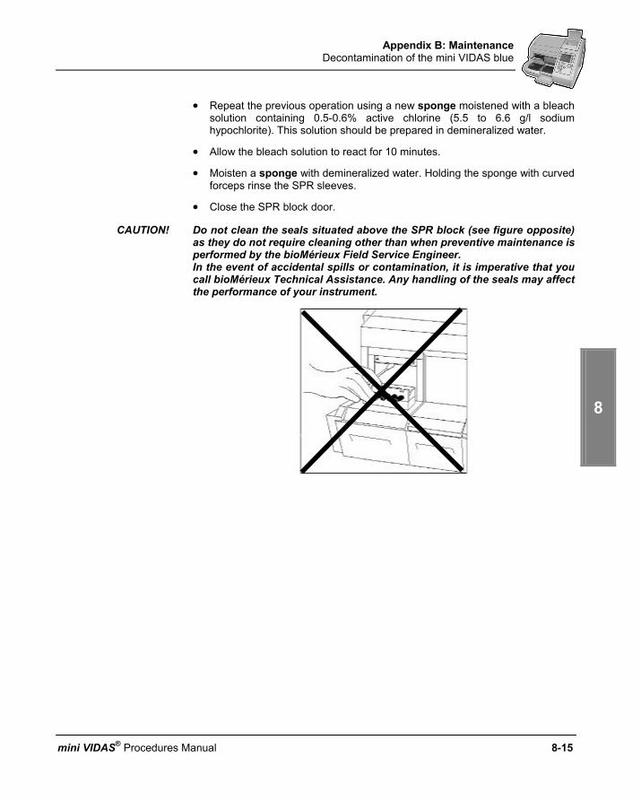
Appendix B: Maintenance Decontamination of the mini VIDAS blue
6
7
8
9
10
mini VIDAS® Procedures Manual 8-15
• Repeat the previous operation using a new sponge moistened with a bleach solution containing 0.5-0.6% active chlorine (5.5 to 6.6 g/l sodium hypochlorite). This solution should be prepared in demineralized water.
• Allow the bleach solution to react for 10 minutes.
• Moisten a sponge with demineralized water. Holding the sponge with curved forceps rinse the SPR sleeves.
• Close the SPR block door.
CAUTION! Do not clean the seals situated above the SPR block (see figure opposite) as they do not require cleaning other than when preventive maintenance is performed by the bioMérieux Field Service Engineer. In the event of accidental spills or contamination, it is imperative that you call bioMérieux Technical Assistance. Any handling of the seals may affect the performance of your instrument.

Appendix B: Maintenance Decontamination of the mini VIDAS blue
8-16 m
Cleaning the str ip preparation tray (monthly)
• Lift the handle on the strip preparation tray ①The strip preparation tray will open.
Fig. 8 ning the strip prep
• Using curved forceps and a sponge moisteclean the front of the strip preparation traysliding the sponge along each one (see the f
Fig. 8-5: Cleaning the strip pre• Repeat the previous operation using a new s
solution containing 0.5-0.6% active chlohypochlorite). This solution should be prepar
• Allow the bleach solution to react for 10 minu• Carefully rinse using curved forceps and a
demineralized water.
②
④③
and tilt the tray forwards ②.
①
aration tray
-4: Opeini VIDAS® Procedures Manual
ned with a detergent, carefully ③ and the 6 channels ④ by igure below).
paration tray ponge moistened with a bleach rine (5.5 to 6.6 g/l sodium ed in demineralized water. tes. new sponge moistened with

Appendix B: Maintenance Decontamination of the mini VIDAS blue
6
7
8
9
10
mini VIDAS® Procedures Manual 8-17
Cleaning the reagent str ip trays (monthly)
• Raise the strip preparation tray until it is in its upright position.
• Use a suitable screwdriver to remove the 2 screws ① located under the strip preparation tray.
• Open the strip preparation tray by tilting it forwards.
Fig. 8-6: Dismantling the strip preparation tray
• With one hand (finger and thumb), grasp the 2 tabs inside the strip preparation tray, squeeze gently and pull forwards to remove the tray (see the figure below).
Fig. 8-7: Removing the strip preparation tray
This gives access to the reagent strip tray.
①

Appendix B: Maintenance Decontamination of the mini VIDAS blue
8-18 mini VIDAS® Procedures Manual
• Manually pull the reagent strip trays ② to their outermost position (see figure below).
Fig. 8-8: Cleaning the reagent strip trays
• Moisten a sponge in the detergent solution. Holding the sponge with curved forceps, carefully clean the 6 channels of the reagent strip tray by sliding the sponge along each channel.
• Repeat the previous operation using a new sponge moistened with a bleach solution containing 0.5-0.6% active chlorine (5.5 to 6.6 g/l sodium hypochlorite). This solution should be prepared in demineralized water.
• Allow the bleach solution to react for 10 minutes.
• Moisten a new sponge with demineralized water. Holding the sponge with curved forceps, rinse each tray.
• Push the reagent strip trays back in until they engage the tray drive mechanism. You will feel a slight resistance during engagement.

Appendix B: Maintenance Decontamination of the mini VIDAS blue
6
7
8
9
10
mini VIDAS® Procedures Manual 8-19
Cleaning the plast ic trays (monthly or in the event of accidental spi l ls)
• Remove the plastic tray ③ that sits underneath each reagent strip tray by sliding it towards you (see figure below).
Fig. 8-9: Cleaning the plastic tray
• Clean each tray with a sponge moistened with a detergent solution.
• Repeat the previous operation using a new sponge moistened with a bleach solution containing 0.5-0.6% active chlorine (5.5 to 6.6 g/l sodium hypochlorite). This solution should be prepared in demineralized water.
• Allow the bleach solution to react for 10 minutes.
• Moisten a new sponge with demineralized water. Holding the sponge with curved forceps, rinse each tray.
• Carefully replace each tray . The edges of the tray must fit into the plastic grooves on each side.
IMPORTANT! The tray must slide BELOW the electric wire that is underneath the reagent strip tray.

Appendix B: Maintenance Decontamination of the mini VIDAS blue
8-20 mini VIDAS® Procedures Manual
Reassembling the str ip preparat ion tray and powering on the analyt ical module
Reassembling the str ip preparat ion tray
CAUTION! Wait until all the parts are dry before reassembling them.
• Slide the strip preparation tray into its housing.
A “click” indicates that the tray has been properly reassembled.
• Raise the strip preparation tray until it is in its upright position and screw the 2 screws back into place.
• Slide the strip preparation tray downwards.
CAUTION! The mini VIDAS blue should not be used when the strip preparation tray is not in place.
Powering on the analyt ical module
• Reconnect the module to the power supply.
• Turn the power switch to the "ON" position.
• Allow the module to warm up for 45 minutes.
• Turn the power switch to the "OFF" position.
• Wait for approximately 1 minute and turn the power switch to the "ON" position.
• Wait for the module to reset (approximately 10 minutes) before attempting to use it again.
IMPORTANT! Discard the sponges and swabs according to acceptable procedures for biohazardous material.
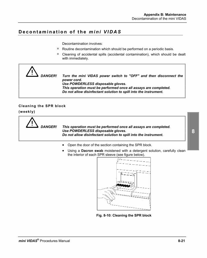
Appendix B: Maintenance Decontamination of the mini VIDAS
6
7
8
9
10
mini VIDAS® Procedures Manual 8-21
D e c o n t a m i n a t i o n o f t h e m i n i V I D A S
Decontamination involves: ∗ Routine decontamination which should be performed on a periodic basis. ∗ Cleaning of accidental spills (accidental contamination), which should be dealt
with immediately.
DANGER! Turn the mini VIDAS power switch to "OFF" and then disconnect the power cord. Use POWDERLESS disposable gloves. This operation must be performed once all assays are completed. Do not allow disinfectant solution to spill into the instrument.
Cleaning the SPR block (weekly)
DANGER! This operation must be performed once all assays are completed. Use POWDERLESS disposable gloves. Do not allow disinfectant solution to spill into the instrument.
• Open the door of the section containing the SPR block. • Using a Dacron swab moistened with a detergent solution, carefully clean
the interior of each SPR sleeve (see figure below).
Fig. 8-10: Cleaning the SPR block

Appendix B: Maintenance Decontamination of the mini VIDAS
8-22 mini VIDAS® Procedures Manual
• Repeat the previous operation using a new Dacron swab moistened with a bleach solution containing 0.5-0.6% active chlorine (5.5 to 6.6 g/l sodium hypochlorite). This solution should be prepared in demineralized water.
• Allow the bleach solution to react for 10 minutes.
• Rinse each SPR sleeve using a new Dacron swab moistened with demineralized water.
• Using curved forceps, moisten a sponge with detergent and swab the rear
of the SPR block, pushing each SPR sleeve individually back towards the interior of the section (see figure below).
Fig. 8-11: Cleaning the rear of the SPR block
• Repeat the previous operation using a new sponge moistened with a bleach solution containing 0.5-0.6% active chlorine (5.5 to 6.6 g/l sodium hypochlorite). This solution should be prepared in demineralized water.
• Allow the bleach solution to react for 10 minutes.
• Moisten a sponge with demineralized water. Holding the sponge with curved forceps rinse the SPR sleeves.
• Close the SPR block door.

Appendix B: Maintenance Decontamination of the mini VIDAS
6
7
8
9
10
mini VIDAS® Procedures Manual 8-23
CAUTION! Do not clean the seals situated above the SPR block (see figure opposite) as they do not require cleaning other than when preventive maintenance is performed by the bioMérieux Field Service Engineer. In the event of accidental spills or contamination, it is imperative that you call bioMérieux Technical Assistance. Any handling of the seals may affect the performance of your instrument.
Cleaning the reagent str ip trays (monthly)
• Remove the screws from the front panel of the module below the reagent strip trays and pull the panel off (see figure below). Make sure you do not let go of the front panel when removing it (it is not equipped with a cord connecting it to the mini VIDAS to prevent it from falling).
Fig. 8-12: Removing the front panel

Appendix B: Maintenance Decontamination of the mini VIDAS
8-24 mini VIDAS® Procedures Manual
• Manually pull the reagent strip trays ② to their outermost position (see figure below).
Fig. 8-13: Cleaning the reagent strip trays
• Moisten a sponge in the detergent solution. Holding the sponge with curved forceps, carefully clean the 6 channels of the reagent strip tray by sliding the sponge along each channel.
• Repeat the previous operation using a new sponge moistened with a bleach solution containing 0.5-0.6% active chlorine (5.5 to 6.6 g/l sodium hypochlorite). This solution should be prepared in demineralized water.
• Allow the bleach solution to react for 10 minutes.
• Moisten a new sponge with demineralized water. Holding the sponge with curved forceps, rinse each tray.
• Push the reagent strip trays back in until they engage the tray drive mechanism You will feel a slight resistance during engagement
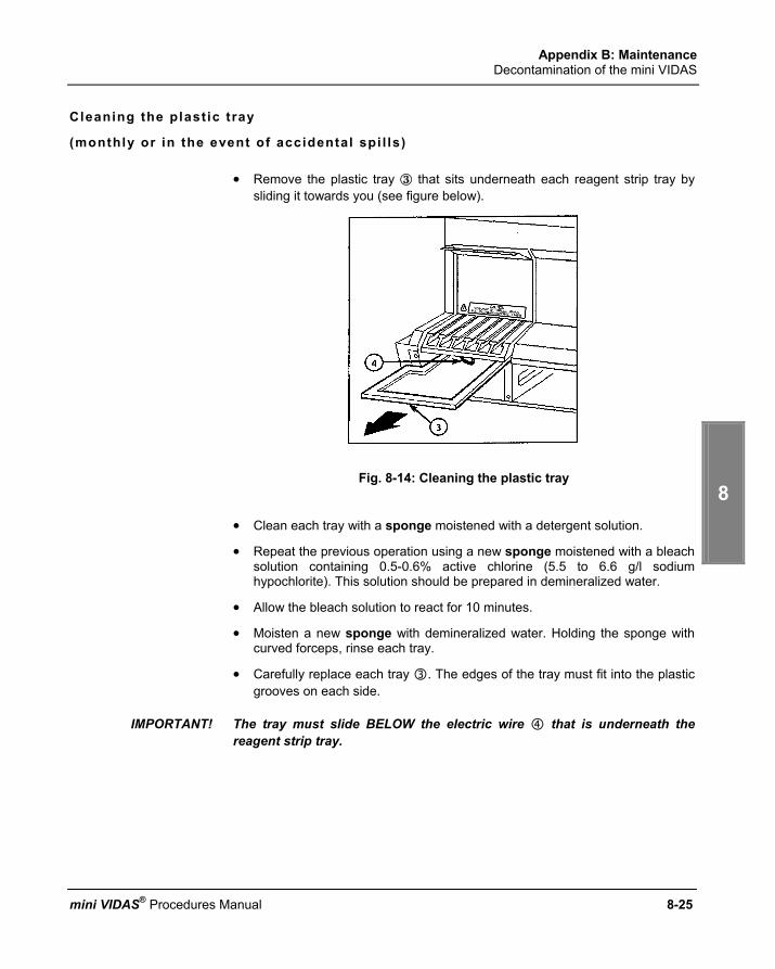
Appendix B: Maintenance Decontamination of the mini VIDAS
6
7
8
9
10
mini VIDAS® Procedures Manual 8-25
Cleaning the plast ic tray
(monthly or in the event of accidental spi l ls)
• Remove the plastic tray ③ that sits underneath each reagent strip tray by sliding it towards you (see figure below).
Fig. 8-14: Cleaning the plastic tray
• Clean each tray with a sponge moistened with a detergent solution.
• Repeat the previous operation using a new sponge moistened with a bleach solution containing 0.5-0.6% active chlorine (5.5 to 6.6 g/l sodium hypochlorite). This solution should be prepared in demineralized water.
• Allow the bleach solution to react for 10 minutes.
• Moisten a new sponge with demineralized water. Holding the sponge with curved forceps, rinse each tray.
• Carefully replace each tray . The edges of the tray must fit into the plastic grooves on each side.
IMPORTANT! The tray must slide BELOW the electric wire that is underneath the reagent strip tray.
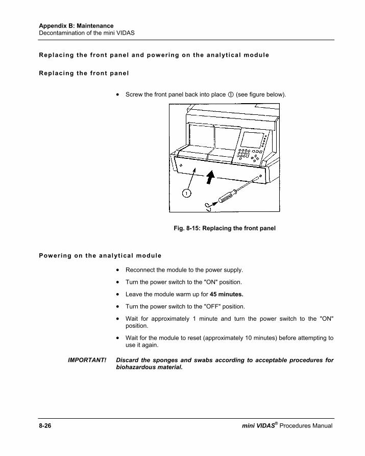
Appendix B: Maintenance Decontamination of the mini VIDAS
8-26 mini VIDAS® Procedures Manual
Replacing the front panel and powering on the analyt ical module
Replacing the front panel
• Screw the front panel back into place (see figure below).
Fig. 8-15: Replacing the front panel
Powering on the analyt ical module
• Reconnect the module to the power supply.
• Turn the power switch to the "ON" position.
• Leave the module warm up for 45 minutes.
• Turn the power switch to the "OFF" position.
• Wait for approximately 1 minute and turn the power switch to the "ON" position.
• Wait for the module to reset (approximately 10 minutes) before attempting to use it again.
IMPORTANT! Discard the sponges and swabs according to acceptable procedures for biohazardous material.

Appendix B: Maintenance Using the quality control test
6
7
8
9
10
mini VIDAS® Procedures Manual 8-27
U s i n g t h e q u a l i t y c o n t r o l t e s t (monthly)
The mini VIDAS quality control test is a simple and rapid technique for testing the pipette mechanisms of the mini VIDAS for correct operation. This test must be performed at least once a month, at the time of preventive maintenance or anytime that a pipetting problem is suspected.
∗ For further information on the test principle, refer to package insert included in the kit. You must read the package insert carefully before performing the test.
C l e a n i n g t h e c o m p u t e r s c r e e n a n d k e y p a d (as required)
• Turn the mini VIDAS power switch to the "OFF" position.
• Clean the screen with a dry antistatic cloth or, if necessary, use a soft cloth moistened with a special product for cleaning screens.
• Turn the power switch to the "ON" position.
C l e a n i n g t h e b a r c o d e r e a d e r (as required)
• Clean the reader window using a soft cloth.
.


mini VIDAS® Procedures Manual 8-29
Appendix C: Qual i ty contro l
C h e c k i n g p e r f o r m a n c e
Optics for the mini VIDAS The mini VIDAS optical system measures the concentration of the reaction product developed during an assay with a single channel fluorometer. This optical system uses a dual beam excitation system to compensate for variations in the lamp output. The optical system can be moved across the instrument to read the desired test position. The reaction product then produces a fluorescence signal proportional to its concentration.
How it works Excitation optics consists of a xenon flash lamp source filtered by a 370 nm narrow band optical filter. Multiple flashes are triggered under computer control and projected as a collimated image of the arc from the flash lamp across the optical window of the cuvette. The detection optics measures the signal using a lens that focuses on the center of the cuvette at a 90 degree angle from the excitation source. The lens projects an image of the center of the cuvette through a 450 nm narrow band filter onto a fast, high sensitivity PIN photodiode. A fraction of the excitation beam is reflected by a sapphire beam-splitter through a UV pass filter onto a reference photodiode producing a signal proportional to the intensity of the excitation beam. Optical readings are measured by the system as a ratio of the detected light to the intensity of the flashlamp, allowing the electronics to compensate for changes in the intensity of the flashlamp. Each flash of the excitation lamp produces output pulses from the signal and reference photodiodes. The maximum amplitude of each pulse is held by high linearity peak detectors. The outputs of the peak detectors are applied to a 12 bit analog to digital converter producing an output proportional to the ratio of the emission intensity to the excitation intensity. Each reading cycle consists of a set number of flashes by the lamp. A group of high and low readings are discarded to filter noise components and the average of the remaining readings are computed to provide the final value calibrated in RFU (relative fluorescence units).

Appendix C: Quality control Checking performance
8-30 mini VIDAS® Procedures Manual
Manual opt ics cal ibrat ion
Instrument calibration is provided using a standard calibration solution in a VIDAS strip prepared by bioMérieux® SA. These calibration strips are checked by QC/QA and values are assigned to the strip [approximately a 3,200 RFU reading with an 8,000 nM solution of 4-methylumbelliferone (4-MU) in a buffer]. Instrument calibration should be checked every 12 months by bioMérieux Technical Assistance.
Self diagnostics
Internal self diagnostics of the optics include computations that monitor the CVs of the readings and will issue warning messages if wide scattering of the data within the readings of a cuvette is detected. The computer also periodically takes readings in air and issues a message if the air readings fall out of expected bounds.

Appendix C: Quality control Auto-calibration of the optical system
6
7
8
9
10
mini VIDAS® Procedures Manual 8-31
A u t o - c a l i b r a t i o n o f t h e o p t i c a l s y s t e m
The mini VIDAS optical system has been proven to be highly reliable and stable over many years of use. To further verify the performance of the optical system, mini VIDAS also uses the optical reference to detect instrument problems before they have an opportunity to impact the results of an assay. The mini VIDAS incorporates a fluorescent europium material imbedded in an optically transparent polymer as a fluorescence optical reference. This reference allows the mini VIDAS to monitor the condition of the entire optical system for changes that could result in optical drift. The long life reference material is placed in a standard VIDAS cuvette mounted internal to the instrument and placed between bays A and B. The optical system periodically measures the reference and the results are closely monitored by the mini VIDAS to insure there is minimal optical drift between calibrations.
How it works The instrument is calibrated at the appropriate service intervals by the service technician using a standardized solution of 4 MU in a buffer. Once the instrument is properly calibrated, the technician instructs the mini VIDAS to measure the built-in reference standard. The value of this reading is stored by the mini VIDAS into non-volatile memory and becomes a reference point for future calibration checks. An advantage of this approach is the internal reference is recalibrated every time the instrument is recalibrated. In normal operation, the mini VIDAS periodically measures (approximately once every 12 hours) the reference during an idle period and compares the result to the one stored when the instrument was calibrated.

Appendix C: Quality control Auto-calibration of the optical system
8-32 mini VIDAS® Procedures Manual
∗ If the result is outside of the internal adjustment range (±0.6%o or approx. ±19 at 3,200 RFU), the mini VIDAS automaticaily readjusts the optical system to bring the result back within the expected range (± 0.4%o or approx. ± 14 at 3,200 RFU).
Moderate drift in the optical system is detected and reported in an error message (error 160), unless the error occurs while your analytical module is warming up (see section "Starting the mini VIDAS" in Chapter 3 of this manual). Call bioMérieux Technical Assistance so that the instrument can be checked before a problem arises.
∗ If calibration from one reference check to the next is more than ± 3% (approx. ± 96 at 3,200 RFU), a warning message is issued to alert the operator to the calibration adjustment and to call bioMérieux Technical Assistance.
Significant optical drift since the last calibration is detected and reported as an instrument error.

Appendix C: Quality control Pipetting for the mini VIDAS
6
7
8
9
10
mini VIDAS® Procedures Manual 8-33
P i p e t t i n g f o r t h e m i n i V I D A S
The mini VIDAS handles reagents via two six-pipettor channels (1 system per section), which carry out all reagent transfers, dilution and washing by means of the SPRs. Liquid volumes within the 8.9 µl to 316.5 µl range can be accommodated by the pipettors. The entire module can move up and down, allowing the SPRs to access wells in the reagent strip. The six pipettor channels are physically independent, but mechanically linked to act in unison.
How it works Fluids move in and out of each SPR channel by using an air displacement piston. The piston is sealed using a low action rolling diaphragm that maintains a constant effective piston area throughout its operating range. The geometry of the actuating system is designed to provide a linear translation of the actuator motion to piston movement and thus fluid displacement. Pipetting volume and the speed at which fluids are moved into or out of the SPR are microprocessor controlled and programmable via protocol commands. A linear stepper motor is used to product the precise linear motion required by the module.
Pipett ing cal ibrat ion and sel f diagnostics The volume accuracy of the fluid displacement is controlled by precision machining of the critical geometries in the pipettor at the time of manufacture. Field calibration of the pipettor assembly is not required. Manufacturing verification of pump accuracy includes physical inspection of the components, pressure/volume testing of each assembled module and fluid transfer testing of the assembled instrument prior to shipment . When running an assay, optical sensors and the microprocessor monitor the linear motion in the pipetting system. If a deviation in the expected linear displacement occurs, the assay is automatically halted and an error message is issued via the computer to the operator. Field checks of the pipettor accuracy may be accomplished by using bioMérieux controls.

Appendix C: Quality control Temperature validation for the mini VIDAS
8-34 mini VIDAS® Procedures Manual
Using the reagent for test ing the pipette mechanisms
Reagent for testing pipette mechanisms: Quality Control VIDAS (QCV): Reference 30706. This control reagent is a simple and rapid technique for testing the pipette mechanisms of your mini VIDAS instrument. You must perform the Quality Control VIDAS test on all the mini VIDAS instrument positions at least once a month, or anytime that a pipetting problem is suspected. For further information on this test, refer to the package insert included in the kit. Read the package insert carefully before performing the test.
T e m p e r a t u r e v a l i d a t i o n f o r t h e m i n i V I D A S
How i t works The temperature of each tray and SPR block in the mini VIDAS instrument is independently controlled and monitored. Each tray and SPR block contains a highly accurate and stable temperature sensing device called a thermistor. As each thermistor assembly is manufactured, it is tested for conformance to its specified tolerance with temperature measurement devices traceable back to an NIST (National Institute of Standards and Technology) temperature standard ITS-90. The thermistors used in the mini VIDAS are 0.2°C accurate and only the devices which can pass that test criteria as they are manufactured are accepted for use in the instruments.
Self diagnostics The software controlling the instrument runs an algorithm which measures the temperature at each thermistor every 60 seconds. This algorithm checks these temperatures and verifies that the temperature across all SPR blocks within an instrument is ± 0.7°C and that the temperature across all trays within the instrument is ± 1°C. In addition to these consistency measurements, an absolute measurement comparison is made to insure that the temperature at any thermistor is also within specified range. If any of these checks fails, the instrument will report an error to the user and the assay being run on the out-of-specification section will be aborted. No other assays can be run until the out-of-specification condition is resolved.

Appendix C: Quality control mini VIDAS master curve establishment and calibration
6
7
8
9
10
mini VIDAS® Procedures Manual 8-35
m i n i V I D A S m a s t e r c u r v e e s t a b l i s h m e n t a n d c a l i b r a t i o n
Defini t ions and principles of cal ibrat ion/recal ibrat ion Master curve The master curve is established at the time of manufacfure for each lot of
reagents. It establishes the mathematical relationship of RFV versus concentration and is provided vith each kit.
Calibration curve The customer defines a curve specific to a particular mini VIDAS instrument by recalibrating the master curve using the recalibrator provided in the kit. The term "calibration curve" refers to the curve after it has been recalibrated by the customer.
Establ ishing the master curve (performed at the factory) The principle consists of determining the mathematical equation which represents the relationship between RFV and the concentration of the analyte being tested. Well defined reference solutions (standards) are used to make this determination. One of the following three mathematical models is used to define the master curve: Rodbard (4 parameter logistic), Semilog or Polynomial. Each assay is associated with a particular mathematical model based on the fundamental properties of that assay. For example, the Rodbard model is used for CMVG, TXG, FER, LH, FSH, TSH, FT4, HCG, T4, DIG, THEO and T3. The semilog model is used for RBG. The polynomial model is used for E2II. The factory-defined master curve is determined during the production of each new lot of SPRs and reagent strips. To determine the master curve, the standards are tested in seven different runs on the same VIDAS instrument. The mean curve of these seven runs becomes the master curve. Four points from the master curve, which uniquely and completely specify the curve, become the master curve data. These data are specific for a certain manufacturing lot, and are encoded in a bar code on a Master Lot Sheet included in each kit.

Appendix C: Quality control mini VIDAS master curve establishment and calibration
8-36 mini VIDAS® Procedures Manual
Establ ishing the cal ibrat ion curve (performed by the customer) Each laboratory must establish its own Calibration Curve. This function is called recalibration and is based on the mathematical master curve data and the test results of one or two standards tested in duplicate or triplicate by the customer. Recalibration serves to control for minor variations in assay signal from one VIDAS instrument to another and is therefore specific for each instrument. On receipt of a new lot of reagents, the customer must enter the master curve data. It may be entered by a bar code scanner or manual entry of the codes. The customer runs the standard(s) in duplicate or triplicate to define the instrument-specific calibration curve. The calibration curve is valid for an extended period of time specified for each assay (14 days). After this time the software requires another calibration. This recalibration over time accommodates minor variations in assay signal throughout the shelf-life of the kit. The calibration curve is valid for analyte concentrations between zero and the standard (from the master curve data) with the highest concentration. If the RFV is higher or lower (depending on the type of assay) than the signal of this highest standard, the message "greater than the concentration of (assay dependent standard)" is given.

Appendix C: Quality control mini VIDAS master curve establishment and calibration
6
7
8
9
10
mini VIDAS® Procedures Manual 8-37
Master lot data Each kit contains an MLE (Master Lot Entry) card printed with the bar code readable data needed for establishing the calibration curve for that assay. Although it is included in each kit, the data need only be entered once for each lot of reagents. The card contains the following information: − 4 RFV numbers, corresponding to four points identified from the master
curve. The corresponding analyte concentration levels for these four points are uniquely specified in the software for each assay.
For example, for Ferritin, standard 1 = 5 ng/ml standard 2 = 150 ng/ml standard 3 = 500 ng/ml standard 4 = 1200 ng/ml.
The RFVs given on the master lot sheet are the values situated precisely on the master curve established at the factory. The VIDAS software calculates the total curve from these data (concentrations and RFV). − Name of the test − Lot number of SPRs and reagent strips (which is used to link the master
curve data with the strip lot number) − Mathematical model used to establish the master curve (7 = Rodbard, 8 =
polynomial, 9 = semilog) − Dose value for the standard(s) − Dose value range for the controls − RFV range for the standard(s) A checksum is established to ensure that there is no transmission error (manually or by bar code) in the series of characters of each line.


mini VIDAS® Procedures Manual 8-39
A p p e n d i x D : I n s t a l l i n g o pt i o n a l e x t e r n a l h a r d w a r e
E x t e r n a l p r i n t e r
Materials required − Compatible printer.
For information on the recommended type of printer, call bioMérieux® or your local bioMérieux representative.
− PC compatible printer cable, having a DB 25-pin connector on one end and a 36-pin Centronix connector on the other end.
− Small, flathead screwdriver. Before instal lat ion
∗ Prior to installing the printer, • Make sure that the mini VIDAS has been configured to use an external
printer. • Refer to chapter 3, page 3-19, "Selecting the printer" and perform this
procedure, selecting the [external printer] option.
Instal lat ion Step 1 • Turn power to the mini VIDAS off. Step 2 • Set the printer near the mini VIDAS within reach of the printer cable and an
appropriate electrical outlet. Step 3 • Locate the Printer Port on the rear of the mini VIDAS. The arrow in the
figure below indicates its location.
Fig. 8-16: Location of printer port
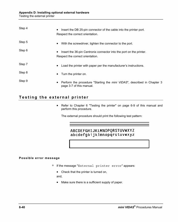
Appendix D: Installing optional external hardware Testing the external printer
8-40 mini VIDAS® Procedures Manual
Step 4 • Insert the DB 25-pin connector of the cable into the printer port.
Respect the correct orientation.
Step 5 • With the screwdriver, tighten the connector to the port.
Step 6 • Insert the 36-pin Centronix connector into the port on the printer. Respect the correct orientation.
Step 7 • Load the printer with paper per the manufacturer’s instructions.
Step 8 • Turn the printer on.
Step 9 • Perform the procedure "Starting the mini VIDAS", described in Chapter 3 page 3-7 of this manual.
T e s t i n g t h e e x t e r n a l p r i n t e r
• Refer to Chapter 6 "Testing the printer" on page 6-9 of this manual and perform this procedure.
The external procedure should print the following test pattern:
Possible error message
∗ If the message "External printer error" appears:
• Check that the printer is turned on, and,
• Make sure there is a sufficient supply of paper.

Appendix D: Installing optional external hardware Installing the bar code reader
6
7
8
9
10
mini VIDAS® Procedures Manual 8-41
I n s t a l l i n g t h e b a r c o d e r e a d e r
Preparing the reader
The reader is supplied in a kit containing:
− 1 bar code reader 1,
− 1 cord 2,
− 1 configuration sheet.
• Connect 2 to 1.
The bar code reader can now be connected to the computer.
Note: The kit must include the above mentioned components. If any are missing, call bioMérieux Technical Assistance or your local bioMérieux representative.
Before instal lat ion
Prior to installing the bar code reader, make sure that the mini VIDAS has been configured to use the correct reader.
1
2

Appendix D: Installing optional external hardware Installing the bar code reader
8-42 mini VIDAS® Procedures Manual
Reading bar codes Step 1 ∗ In the Configuration Menu,
• Select [Barcode Wand]. • Press the <↑> and <↓> keys until the submenu you want appears on the
screen.
Step 2 The following selections appear:
[None] (the default setting) [Barcode Wand]
Note: A ⊠ symbol indicates the current setting. Step 3 • Select [Barcode Wand]. Step 4 ∗ To return to the Configuration Menu,
• Press the <Previous Screen> key.

Appendix D: Installing optional external hardware Installing the bar code reader
6
7
8
9
10
mini VIDAS® Procedures Manual 8-43
Instal l ing the bar code reader wand
Step 1 • Turn power to the mini VIDAS off.
Step 2 • Locate the diagnostic port on the rear of the mini VIDAS. The arrow in the following figure indicates its location.
Fig. 8-17: Location of diagnostic port
Step 3 • Connect the bar code reader cable to the diagnostic port. The port and connector are shaped such that the cable can be successfully inserted in only one orientation.
• Perform the procedure "Starting the mini VIDAS", described in Chapter 3 page 3-7 of this manual.
Step 4 The bar code wand is now ready to use.
∗ If the mini VIDAS was already equipped with a bar code reader, the old reader’s configurations will be replaced by the default configuration of the new bar code reader.
∗ The bar code reader you have received has already been configured by bioMérieux and takes into account most of the existing types of bar codes. Should the reader lose its configuration, • Scan the configuration sheet provided using the reader.

mini VIDAS® Procedures Manual 8-45
Appendix E: Computer in ter face in format ion
I n t r o d u c t i o n
bioMérieux® SA manufactures several different instruments which include the mini VIDAS. There are several different documents pertaining to the computer interface specifics for these different types of instruments. The mini VIDAS is a standalone instrument that does not use a separate computer. The mini VIDAS instruments at version VIC-R∅ 2.15 software (or subsequent version) contain all that is necessary to support a literal unidirectional computer interface. This interface allows the mini VIDAS results to be transmitted (i.e., uploaded) to the Laboratory Information System (LIS) or other host computer system. The same communications protocol that is used by the VIDAS model is also used by the mini VIDAS, with one exception. The serial communications parameter number of stop bits is fixed at one (1). This protocol is described in detail in the bioMérieux Interface Products Specification. This particular document should be referred to for further information in this area.
∗ Please note the following: − The mini VIDAS interface does not require the presence of a bioMérieux
Nerve Center or CC1 computer, as mentioned earlier. The mini VIDAS at version VIC-R∅ 2.15 software(or subsequent version) contains the necessary software and hardware for the interface.
− Cable Specifications: Follows the NCII DB9 layout as described in the Communications section of the Interface Product Specification.
− The Download section of the Interface Products Specification mentioned above does not apply to the mini VIDAS. The mini VIDAS transmits only to the host computer (i.e., uploads test results).
− Section 3.1 - Field Types in the Upload section of the Interface Products Specification mentioned above lists those fields that are transmitted to the host computer (under the column VID).

Appendix E: Computer interface information Introduction
8-46 mini VIDAS® Procedures Manual
− The pn and pi fields (patient name and patient identification) are not transmitted as part of the upload on a mini VIDAS.
− The mini VIDAS fields are relatively few and are systematically transmitted. The mini VIDAS fields that are transmitted include :
. mtrsl message type
. pi patient ID
. pn patient name
. si specimen separator
. ci sample ID
. rt short assay name
. rn long assay name
. ql qualitative result
. qn quantitative result
. tt test completion time
. td test completion date
. qd dilution (optional)
(See the Upload section of the Interface Products Specification for further information if needed).
∗ A list of the mini VIDAS assays can be obtained directly from the mini VIDAS instrument.
• Select [Utilities] from the screen, then [Miscellaneous Functions].
∗ From there,
• Select [Version Menu], then [Print Assay Version]. This will provide a printout of the available assays if needed.

Appendix E: Computer interface information Introduction
6
7
8
9
10
mini VIDAS® Procedures Manual 8-47
∗ To verify the software version on a particular mini VIDAS instrument,
• Select [Utilities] and [Miscellaneous Functions].
∗ From there,
• Select [Version Menu] and then [Show Software Version].
∗ Results that are not uploaded :
. Strips without a sample ID
. QCV, OPT, LEAK.
. Any raw result analysis type assays
. Controls
. Standards.
∗ If attempts to upload results are unsuccessful, once the retry interval and number of retries (as specified in the LIS Interface Options) have elapsed, an error will be logged. To view this log,
• Select the <?> on the keypad or view saved errors from the utility menu selection.
mini VIDAS results are not permanently stored in the instrument. Uploads should be performed on a routine basis.

Appendix E: Computer interface information Configuration information
8-48 mini VIDAS® Procedures Manual
C o n f i g u r a t i o n i n f o r m a t i o n
IMPORTANT! Please note that the number of stop bits is fixed at one (1) for the mini VIDAS.
∗ From the Utility Menu,
• Select the configuration menu option and then select LIS Interface Options to get to the options.
LIS user opt ions (Enable the interface here).

Appendix E: Computer interface information Configuration information
6
7
8
9
10
mini VIDAS® Procedures Manual 8-49
LIS interface options
Minim. Maxim. Default Communications Settings − Baud Rate 300 38400 1200
− Parity ( None, Odd, Even, Low, High ) none
− Character Size 7 8 8
Timeouts & Limits − Timeout 2 99 3
− Checksum Retry Limit 0 99 3
− Checksum Error Retry Interval 0 99 10
− <ENQ> Retry Limit 0 99 3
− <ENQ> Retry Interval 0 99 10
− InterRecord Delay 0 99 0
− InterMessage Delay 0 99 2
Data Format Misc. Format Alternate Protocol
STX : <CR><LF> ETX : <CR><LF> RS : <CR><LF> GS : <CR><LF> ENQ : <CR><LF> EOT : <CR><LF> Send Dilution
Time Separator Date Separator Field Terminator
. : / - ,
. : / - , ! @ # $ % ^ & * ( ) – = + < > / ? [ ] \ | { }
: / |
Send Test Message (Use to send a test pattern message).
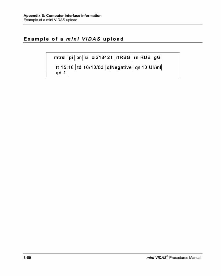
Appendix E: Computer interface information Example of a mini VIDAS upload
8-50 mini VIDAS® Procedures Manual
E x a m p l e o f a m i n i V I D A S u p l o a d

mini VIDAS® Procedures Manual 9-1
9 Glossary
Assay A complete test procedure using immunological methods and fluorescent
chemistry to detect or quantify an analyte. Assay analysis Interpretation of data using sample assay data, standard assay data, and
thresholds for data comparison. These calculations can be different for each type of assay and can interpret the assay result.
Assay code A two-, three-, or four-character designation for an assay used in the
mini VIDAS. Assays are defined in the mini VIDAS, for example, using the assay code.
Assay Compatibility The property that two or more assay types have when they utilize the same
protocol in the mini VIDAS. Assay kit A package containing a set of reagent strips, SPR®s, and a package insert
along with any necessary controls, standards, and sample treatment reagents.
Background The native fluorescence that a substrate has without the intended chemical reaction for the assay.
Bar code A series of lines printed on the label of a reagent strip. The encoded information
can be read and interpreted by the scanner and used to identify the strip.
Calibration The process of adjusting the standard curve of a quantitative assay lot or storing the calibrator's RFV for a qualitative assay.
Calibration curve A set of data, supplied by bioMérieux® with each lot of a quantitative assay, that
becomes the standard curve for that lot. Central processing unit
The portion of a computer that is responsible for processing software instructions.

Glossary
9-2 mini VIDAS® Procedures Manual
Cuvette The last of the 10 wells of the reagent strip. It is made of optically clear plastic
that permits the scanner to take an accurate fluorometric reading of the substrate.
Defined run An assay run in which assay types, sample IDs, standards, and controls are
defined on the mini VIDAS prior to the start of the run. Dual reagent strip A strip consisting of a jointly attached sample reference reagent strip (left) and a
sample test reagent strip (right). Equivocal An assay analysis result that is neither positive/reactive nor
negative/nonreactive; it falls between the high and low threshold values for the test.
Fluorescence A physical process in which a substance, after exposure to light at a specific
wavelength, emits light at another wavelength. This is the process used for analyte detection in the mini VIDAS.
Fluorescent units A numerical value that represents the intensity of fluorescence detected by the
optical scanner.
Load and Go run An assay run in which reagent strips are placed into the mini VIDAS and run
without any prior definition on the mini VIDAS.
Master lot data A set of data, supplied by bioMérieux with each lot of an assay that supplies quality control ranges and, for quantitative assays, becomes the standard curve for that lot.
MLE card The Master Lot Entry, or MLE card, is used to enter master lot data into the
mini VIDAS. The card is printed with bar coded data that is read on a section of the instrument.
Online help A screen display of a mini VIDAS data directory that can be activated during
the execution of another program.

Glossary
6
7
8
9
10
mini VIDAS® Procedures Manual 9-3
Optical cuvette The last of the ten wells of the reagent strip. It is made of optically clear plastic
that permits the scanner to take an accurate fluorometric reading of the substrate.
Optical scanner A component of the mini VIDAS that reads the bar code label and measures
the intensity of fluorescence of the assay.
Paging The process of displaying additional or previous information in a directory that does not fit on one display screen.
Port A cable connection site on the back of the mini VIDAS.
Position The reagent strip and SPR slots in the mini VIDAS where a reagent strip/SPR pair can be placed.
Protocol A specific sequence of computer-controlled activities (pipetting, mixing, incubating, reading, etc.) needed to perform an assay. Only assays with identical Protocols can be run in the same section.
Reagent strip A polypropylene strip consisting of 10 wells with a foil seal and paper label. One well of the strip is for the sample. The other eight wells contain the various reagents required for the immunoassay. The last well of the strip is the optical cuvette that contains the substrate.
Reagent strip compartment
A temperature-controlled tray with a plastic cover containing six section channels that hold six reagent strips or three dual reagent strips.
Reagent strip tray The temperature-controlled tray within the reagent strip compartment. Also
called section tray. Reference strip The reagent strip in a dual strip pair that is used to measure the background
reading for the sample.
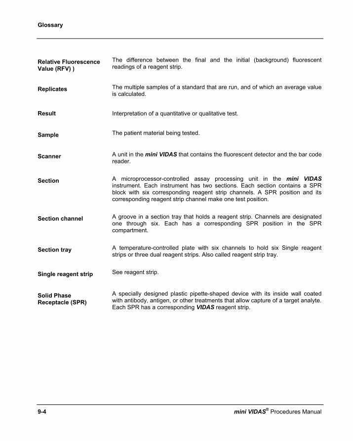
Glossary
9-4 mini VIDAS® Procedures Manual
Relative Fluorescence Value (RFV) )
The difference between the final and the initial (background) fluorescent readings of a reagent strip.
Replicates The multiple samples of a standard that are run, and of which an average value
is calculated.
Result Interpretation of a quantitative or qualitative test.
Sample The patient material being tested.
Scanner A unit in the mini VIDAS that contains the fluorescent detector and the bar code reader.
Section A microprocessor-controlled assay processing unit in the mini VIDAS instrument. Each instrument has two sections. Each section contains a SPR block with six corresponding reagent strip channels. A SPR position and its corresponding reagent strip channel make one test position.
Section channel A groove in a section tray that holds a reagent strip. Channels are designated one through six. Each has a corresponding SPR position in the SPR compartment.
Section tray A temperature-controlled plate with six channels to hold six Single reagent strips or three dual reagent strips. Also called reagent strip tray.
Single reagent strip See reagent strip.
Solid Phase Receptacle (SPR)
A specially designed plastic pipette-shaped device with its inside wall coated with antibody, antigen, or other treatments that allow capture of a target analyte. Each SPR has a corresponding VIDAS reagent strip.

Glossary
6
7
8
9
10
mini VIDAS® Procedures Manual 9-5
SPR block A temperature-controlled block with receptacles to hold six SPRs. Each has a
position for a corresponding reagent strip immediately below it in the section. A tilt-down door provides access to the SPR block.
Standard A solution containing a known analyte concentration. The RFV obtained from testing a Standard is used to calculate concentrations and to interpret patient samples or controls.
Stored Standard The test result of a standard, stored as data in the mini VIDAS, and used to calculate results for test samples over a period of time.
Strip preparation tray A tray with 6 positions located under each reagent strip tray. It is used to
prepare tests for a specific section as it can hold either 6 individual strips or the boat included in the reagent kit.
Substrate A substance in the reagent strip that is broken down enzymatically to create a
compound that fluoresces.
Test That portion of an assay kit used to process a specimen, control, or standard; consists of a paired reagent strip and SPR (s).
Test value The result calculated using the Relative Fluorescent Value (RFV) of the sample
and the Relative Fluorescent Value of the reference or of the standard, depending upon whether it is a dual or Single reagent strip, respectively.
Threshold A numerical value stored in the mini VIDAS memory.
It is used to translate the test value to qualitative results such as "positive", "negative", "equivocal".


mini VIDAS® Procedures Manual 10-1
10 Index
Page numbers in bold italics correspond to figures.
A
AC power...................................................................................................................................................... 2-9 Arrow keys.................................................................................................................................................... 2-7 Assay
compatibility.............................................................................................................................................. 4-9 expiration date of .................................................................................................................................... 2-25 normal ranges for ................................................................................................................................... 3-36 report ........................................................................................................................................................ 5-6 report errors............................................................................................................................................ 5-11 running.................................................................................................................................................... 4-13
Assay code .......................................................................................................................................... 2-18, 9-1 Assay kit .............................................................................................................................................. 2-24, 9-1 Auto calibration........................................................................................................................................... 8-31
B
Background .................................................................................................................................................. 9-1 Bar code ....................................................................................................................................................... 9-1
manual entry............................................................................................................................................. 7-9
C
Cable connections ........................................................................................................................................ 2-9 Calibration .................................................................................................................................................... 9-1 Calibration curve.................................................................................................................................... 5-5, 9-1 Central processing unit .......................................................................................................................... 2-6, 9-1 Changing
factory settings ......................................................................................................................................... 6-3 Computer port............................................................................................................................................... 2-9 Configuration menu .................................................................................................................................... 3-11 Controls ...................................................................................................................................................... 4-10 Cuvette ......................................................................................................................................................... 9-2
Index
10-2 mini VIDAS® Procedures Manual
D
Defined run ................................................................................................................................................... 9-2 Diagnostic port..................................................................................................................................... 2-9, 8-43 Dilution
factor....................................................................................................................................................... 4-24 Dual reagent strip .........................................................................................................2-25, 4-16, 5-4, 5-9, 9-2 Dust covers................................................................................................................................................... 3-6
E
Equivocal ...................................................................................................................................................... 9-2 Error
alert system .............................................................................................................................................. 7-2 message list............................................................................................................................................ 7-14 message screens, types ........................................................................................................................... 7-3 printer ............................................................................................................................................ 7-16, 7-25 resolving ................................................................................................................................................... 7-7 start........................................................................................................................................... 2-17, 7-4, 7-7
Error messages autoprinting of ......................................................................................................................................... 3-31
External printer ........................................................................................................................................... 8-39
F
Fluorescence ................................................................................................................................................ 9-2 Fluorescent units .......................................................................................................................................... 9-2 Function keys ........................................................................................................................................ 1-4, 2-7 Fuse compartment........................................................................................................................................ 2-9
H
Halting a section ......................................................................................................................................... 4-46 Hardware
microprocessor ......................................................................................................................................... 2-4 printer port ................................................................................................................................................ 2-9 printer, internal.......................................................................................................................................... 2-7 section ...................................................................................................................................................... 2-3 SPR® block ............................................................................................................................................... 2-4

Index
6
7
10
8
10
mini VIDAS® Procedures Manual 10-3
I
Incubators..................................................................................................................................................... 2-4 Installing
bar code reader wand............................................................................................................................. 8-43 printer paper ........................................................................................................................................... 3-38
K
Keypad ......................................................................................................................................................... 1-4 Keypad and screen....................................................................................................................................... 2-6 Keys
arrow ................................................................................................................................................. 1-4, 2-7 number .............................................................................................................................................. 1-4, 2-7 selection ............................................................................................................................................ 1-5, 2-7 Selection ~................................................................................................................................................ 1-4
L
Label, reagent strip..................................................................................................................................... 2-25 LIS
missing ID option .................................................................................................................................... 3-35 user options for....................................................................................................................................... 3-34
Listing master lots .............................................................................................................................................. 4-45 stored standards..................................................................................................................................... 4-43
Load and Go run........................................................................................................................................... 9-2
M
Maintenance ............................................................................................................................................... 8-11 Master lot data.............................................................................................................................................. 9-2 Master Lot Data ............................................................................................................................................ 5-5 Memory card............................................................................................................................................... 2-23 Memory card data....................................................................................................................................... 6-24 Messages, error.......................................................................................................................................... 2-21 mini VIDAS
menu system .......................................................................................................................................... 2-12 status screen ................................................................................................................................. 2-15, 2-18
MLE card .................................................................................................................................... 4-34, 4-40, 9-2

Index
10-4 mini VIDAS® Procedures Manual
O
Off line, taking a section ............................................................................................................................... 6-2 Online help .......................................................................................................................................... 2-20, 9-2 Optical cuvette ....................................................................................................................................... 2-6, 9-3 Optical scanner............................................................................................................................................. 9-3
P
P/N analysis.................................................................................................................................................. 5-4 P/S analysis .................................................................................................................................................. 5-3 Pipetting...................................................................................................................................................... 8-33 Planning a run .............................................................................................................................................. 4-8 P-N analysis ................................................................................................................................................. 5-4 Ports, cable connection ................................................................................................................................ 9-3 Ports, rear panel ........................................................................................................................................... 2-8 Position......................................................................................................................................... 2-3, 2-18, 9-3 Power switch ................................................................................................................................................ 3-7 Print screen ................................................................................................................................................ 2-20 Printing
assay list ................................................................................................................................................. 5-18 Printing instrument temperatures................................................................................................................ 7-28 Protocols....................................................................................................................................................... 9-3 P-S analysis.................................................................................................................................................. 5-3
Q
Qualitative assay ................................................................................................................................... 5-3, 5-8 Quantitative assay ............................................................................................................................... 5-5, 5-10
R
Reagent strip ................................................................................................................................................ 9-3 bar code for .............................................................................................................................................. 9-1 inserting into tray .................................................................................................................................... 4-14
Reagent strip tray ......................................................................................................................................... 9-3 Reference strip ............................................................................................................................................. 9-3 Relative fluorescence value.................................................................................................................See RFV Report, assay
errors on ................................................................................................................................................. 7-23

Index
6
7
10
8
10
mini VIDAS® Procedures Manual 10-5
Reports qualitative assay ....................................................................................................................................... 5-8
Reprinting, assay report ............................................................................................................................. 5-12 Results
qualitative .......................................................................................................................................... 5-3, 5-4 quantitative ............................................................................................................................................. 5-10
RFV ....................................................................................................................................................... 5-1, 9-4 Run, assay
load and go............................................................................................................................................... 4-8
S
Sample ID defining a character set for ..................................................................................................................... 3-23 entering................................................................................................................................................... 4-18
Scanner ........................................................................................................................................................ 9-4 Screen paging ............................................................................................................................................ 2-21 Section
starting.................................................................................................................................................... 4-14 Selecting
a language......................................................................................................................................... 3-9, 6-5 Selecting the printer.................................................................................................................................... 3-19 Separators, date/time ................................................................................................................................. 3-21 Setting
date and time.......................................................................................................................................... 3-17 date/time format...................................................................................................................................... 3-20 display contrast....................................................................................................................................... 3-18 dose units ............................................................................................................................................... 3-12 report header .......................................................................................................................................... 3-16 user ID.................................................................................................................................................... 3-14
Shipping the mini VIDAS ............................................................................................................................ 6-25 Single reagent strip..................................................................................................................................... 2-24 Software boot sequence............................................................................................................................... 3-8 Solid Phase Receptacle ....................................................................................................................See SPR® Specifications, instrument............................................................................................................................. 8-3 SPR® .......................................................................................................................................... 2-27, 4-22, 9-4 Standards ..................................................................................................................................... 4-10, 5-2, 9-5 Starting
defined run.............................................................................................................................................. 4-16 load and go run....................................................................................................................................... 4-13 section .................................................................................................................................................... 4-14
Status light.................................................................................................................................................... 2-4 Status, system............................................................................................................................................ 2-20 Stored standards
replacing................................................................................................................................................. 5-14 Substrate ...................................................................................................................................................... 9-5
Index
10-6 mini VIDAS® Procedures Manual
T
Temperature ................................................................................................................................................. 8-6 Temperatures, instrument, displaying................................................................................................ 2-17, 7-27 Test value .............................................................................................................................................. 5-2, 9-5 Testing
printer ..................................................................................................................................................... 8-40 Threshold............................................................................................................................................... 5-2, 9-5 Tray, reagent strip......................................................................................................................................... 2-3
U
Unpacking the mini VIDAS ........................................................................................................................... 3-5
V
Validating, LIS results ................................................................................................................................. 5-15 Value
relative fluorescence................................................................................................................................. 5-2 Viewing saved errors .................................................................................................................................. 7-26 Volume
changing the beep .................................................................................................................................. 3-26 changing the keyclick.............................................................................................................................. 3-25 setting final error ..................................................................................................................................... 3-28 setting initial error ................................................................................................................................... 3-27
W
Work flow............................................................................................................................................... 4-3, 4-4

mini VIDAS® Procedures Manual Notes-1
NOTES
.................................................................................................................................................................................................................................................................
.................................................................................................................................................................................................................................................................
.................................................................................................................................................................................................................................................................
.................................................................................................................................................................................................................................................................
.................................................................................................................................................................................................................................................................
.................................................................................................................................................................................................................................................................
.................................................................................................................................................................................................................................................................
.................................................................................................................................................................................................................................................................
.................................................................................................................................................................................................................................................................
.................................................................................................................................................................................................................................................................
.................................................................................................................................................................................................................................................................
.................................................................................................................................................................................................................................................................
.................................................................................................................................................................................................................................................................
.................................................................................................................................................................................................................................................................
.................................................................................................................................................................................................................................................................
.................................................................................................................................................................................................................................................................
.................................................................................................................................................................................................................................................................
.................................................................................................................................................................................................................................................................

NOTES
Notes-2 mini VIDAS® Procedures Manual
................................................................................................................................................................................................................................................................
................................................................................................................................................................................................................................................................
................................................................................................................................................................................................................................................................
................................................................................................................................................................................................................................................................
................................................................................................................................................................................................................................................................
................................................................................................................................................................................................................................................................
................................................................................................................................................................................................................................................................
................................................................................................................................................................................................................................................................
................................................................................................................................................................................................................................................................
................................................................................................................................................................................................................................................................
................................................................................................................................................................................................................................................................
................................................................................................................................................................................................................................................................
................................................................................................................................................................................................................................................................
................................................................................................................................................................................................................................................................
................................................................................................................................................................................................................................................................
................................................................................................................................................................................................................................................................
................................................................................................................................................................................................................................................................
................................................................................................................................................................................................................................................................
................................................................................................................................................................................................................................................................
................................................................................................................................................................................................................................................................


The logo is a registered and protected trademark of bioMérieux sa or one of its subsidiaries.