bhel mechanical training report
DESCRIPTION
BHEL MECHANICAL Training ReportTRANSCRIPT

TRAINING REPORT
OF
SIX MONTHS INDUSTRIAL TRAINING, UNDERTAKEN
AT
“Bharat Heavy Electricals Limited (BHEL), Hardwar”
IN
“MECHANICAL DEPARTMENT”
ON
“PROJECT/WORK ASSIGNED”
SUBMITTED IN PARTIAL FULFILLMENT OF THE DEGREE
OF
BACHELOR OF TECHNOLOGY
IN
MECHANICAL BRANCH
Under the Guidance of: Submitted By: Name: Mr.S.HALDHAR Name: Digvijay junejaDesignation: MANAGER College Roll No.: Y-54109Department: TURBINE BLOCK University Roll No.: L-605114095
1
1

CHANDIGARH-PATIALA NATIONAL HIGHWAY,
VILL. JHANSLA, TEHSIL RAJPURA,DISTT. PATIALA 14040
ACKNOWLEDGEMENT
“Such Thanks I Give
As one near death to those wish him live."
---Shakespeare---
It gives me immense pleasure to present my Project Report before you. I
thankfully acknowledge the staff of BHEL, Haridwar for giving me so much co-
operation and taught lots of new things to me. Which I am sure will help me in my war
future.
A special thanks to Sh. S.Haldar (Sr. Manager,TUM Block-3) to support me
during my Industrial Training. I pay my sincere regards to Mr. Haldar. I also thanks to
Mr. S. Haldar for providing me theoretical material about bhel . I also pay my sincere
regards to my training incharge Mrs ShakunPreet.
“All is well that ends well"
Digvijay juneja
MECHANICAL (4th YEAR) CHITKARA INSTITUTE OF
ENGINEERING & TECHNOLOGY
2
2

INDEX PAGE NO
1. SAFETY ACT 32. COMPANY PROFILE 5
OVERVIEW TO BHEL 6 LOCATION OF BHEL HARIDWAR 11 QUALITY CONFORMATION 18 INTRERNATIONAL OPERATIONS 19 BUSINESS ACTIVITIES 20 CLASSIFICATION OF PRODUCTS 25 HEEP PLANT, HARIDWAR 29 3. DESCRIPTION OF 8 BLOCKS 32 4. BLOCK 3 37 TURBINE BLADES 48 BALANCING TUNNEL 52 5. PROJECT ON STEAM TURBINE 58 INTRODUCTION 58 TYPES 59 MATERIAL SELECTION 62 PRINCIPLE OF OPERATION 62 EFFICIENCY 66 DIFFERENT PARTS OF TURBINE 69 6. GOVERNING SYSTEM 72 7. GOVERNING SYSTEM OF TURBINE 75 8. STEAM TURBINE GOVERNING 78 9. APPLICATION/USES OF STEAM TURBINES 80 10. CFFP PLANT 82 11. ENGINEERING CAPABILITIES 84 12. MANUFACTURING DIVISIONS 86 13. CASE STUDY OF FIXTURE 88 14. CASE STUDY OF TEMPLATE 110 15. BIBLIOGRAPHY 116
3
3

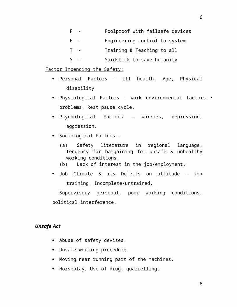
SAFETY
S - Science for Self & Society
A - Art of Action for Accidence Avoidance
F - Foolproof with failsafe devices
E - Engineering control to system
T - Training & Teaching to all
Y - Yardstick to save humanity
Factor Impending the Safety:
Personal Factors – III health, Age, Physical disability
Physiological Factors – Work environmental factors / problems, Rest pause cycle.
Psychological Factors – Worries, depression, aggression.
Sociological Factors –
(a) Safety literature in regional language, tendency for bargaining for unsafe & unhealthy working conditions.
(b) Lack of interest in the job/employment.
Job Climate & its Defects on attitude – Job training, Incomplete/untrained,
Supervisory personal, poor working conditions, political interference.
Unsafe Act
Abuse of safety devises.
Unsafe working procedure.
Moving near running part of the machines.
4
4

Horseplay, Use of drug, quarrelling.
Lack of personal protective equipment.
Lack of attention.
Unsafe Conditions
Inadequate machine guarding.
Defective tools
Unsafe design/construction of the work place.
Improper illumination.
Excess Noise
Poor housing keeping
Excess heat in work place
Safety is the responsibility of every one
One has not only to provide Safe & Best product but also create a climate where
the safe operation can be possible.
The safety means, not only to prevent the accident but also
Control of occupational health
To make machine or equipment or situation totally safe.
Taking in mind for safe operation activities for man, machine, material &
money.
5
5
Company Profile
6
6

BHEL
AN OVERVIEW:
In 1956 India took a major step towards the establishment of its heavy engineering industry when Bharat Heavy Electricals Ltd., (BHEL) setup at Bhopal. It progressed rapidly and three more factories went into production in 1965. The main aim of establishing BHEL was to meet the growing power requirement of the country. BHEL appeared on the power map of India in 1969 when the first unit supplied by it was commissioned at the Basin Bridge Thermal Power Station in Tamilnadu. Within a decade, BHEL had commissioned the 100th unit at Santaldih, West Bengal.
BHEL has taken India from a near total dependence on imports to complete self-reliance in this vital area of power plant equipment. BHEL has supplied 97% of the power generating equipment that was commissioned in India during 1979-80. BHEL has already supplied generating equipment to various utilities produce annually; equipment capable of generating 6000MW. This will grow further to enable BHEL to meet all of India’s projected power equipment requirements, as well as sizeable portion of export targets.
Probably the most significant aspect of BHEL’s growth has been its diversification. The constant reorientation of the organization to meet the varied needs in time with time a philosophy that has led to the development of a total capability – from concept to commissioning not only in the field of energy but also in industry and transportation. In the world power scene, BHEL ranks among the top ten manufacturers of power plant equipment and in terms of the spectrum of products and services offered, it is right on top.
BHEL’s technological excellence and turnkey capabilities have won it world wide recognition. Over 40 countries in the world over have placed orders with BHEL covering individual equipment to complete power stations on a turnkey basis. In 1978-79 export earnings reached Rs.122 crores, the highest for any year.
7
7

BHEL has its headquarters at New Delhi. Its operations are spread over 11 manufacturing plants and number of engineering and service divisions located across the country. The service divisions include a network of regional branch offices throughout India.
Bharat Heavy Electrical Limited (BHEL) is the largest engineering enterprise of its kind in India and is one of the major power plant equipment manufacturers in the world. BHEL’s manufacturing facilities are comparable with the best in the world with modern design, engineering, material preparation, fabrication, welding, heat treatment, handling, testing and shipping facilities. BHEL offers customers worldwide a wide range of products and services that conform to the highest international quality standards and specifications with the added advantages of shorter delivery periods and competitive prices. BHEL has supplied boilers and auxiliaries accounting for nearly 70% of the total installed thermal power generation capacity in India. BHEL utility boilers account for over 65% of the total installed thermal power generation capacity in India. Thermal power stations equipped with BHEL boilers have been regularly winning the Government of India’s awards for performance excellence. BHEL has successfully executed boiler projects in Malaysia and the Middle East and continues to secure repeat orders from overseas customers for servicing and renovation of boilers.
The story starts in 1956 when India took a major step towards the genesis of heavy electrical equipment industry in India, the first plant was established at Bhopal, and the endeavor progressed with establishment of several more plants at different places in India and is now collectively known as BHEL. It has been earning continuously since 1971-72 with a well recognized track record of performance. The turnover of the company in 2004-05 is at the level of 103364 millions and profits are 9534 millions.
BHEL caters to the core sectors of Indian economy, mainly to Power Generation & Transmission, Industry, Transportation, Telecommunication, Renewable energy, Defense etc. It manufactures over 180 products under 30 major product groups. The wide network of BHEL consists of 14 manufacturing units, 4 power sector regional centers, over 100 project sites, 8 service centers and 14 regional offices. The network enables the company to be closer to its customers and provide them with suitable products, systems and services efficiently and at competitive rates.
In 1956, at Bhopal, HEP is established and the production started in 1960. After three years in 1963 the govt. of India established three more plants at Hyderabad, Tiruchi and Haridwar. Hydrabad’s HPEP started production in 1965 and in the same year Tiruchy’s HPBP also went into production; the latest was the Haridwar of these three 1963 borned plants and started in 1967. In 1974 CFFP at Haridwar was established as an additional unit which started production in 1976. Jhansi’s TP began production in 1976. At Tiruchy
8
8

one more plant was established in 1976 which went into production in 1979. A company was established in 1976 as REMCO at Ranipet merged itself with BHEL as BAP in 1980. In 1977 ISG, Banglore was established. REMCO, Banglore, an establishment of 1963 merged with BHEL in 1980 as EDN. In the same year a setup of 1932 merged with BHEL and became the part of Banglore division as EPD. In 1983 at Goindwal IVP was established and started production in 1984. Jagdishpur’ IP and Varanasi’s HERP started their journeys in 1984. Rudrapur got recognition in 1984.Gurgaon’s ASSCP is also a part of BHEL.
This year the 50th anniversary of BHEL has been completed. On this prestigious eve, the company has spent Rs. 17, 41,250 on buying 17000 kg sweets, which has been distributed among all the employees concerned with BHEL. Also, the company has gifted gold coins of 25 grams each, worth Rs. 25000 approximately, to all its employees on this special occasion.
Aimed at preparing to meet the country’s power capacity addition targets toward the agenda of providing power to all by 2012, BHEL is investing more then Rs. 1600 crores for holistic modernization and capacity expansion of its facilities. The focus of the initiative is an addition of facilities for various products in its manufacturing units and for construction tools and equipment for erection and commissioning services at customer project sites.
In the 6th plan itself, a production capacity of 6000 MW has been established by BHEL, which was more than adequate for India’s power capacity addition programmed.
In the 10th plan (2002 – 2007), nearly 34,000 MW of fresh generated capacity is expected to be added in the country, of which BHEL’s contributed would be about 19,500 MW, well within its present production capacity. The capacity of 10000 MW is intended to meet the present indications of the likely power capacity addition target of the 11 th plan 2007 – 2012 of over 62000 MW.
9
9

VARIOUS FACTORIES OF BHEL AND
THEIR
MAIN PRODUCTS
FACTORIES
BHOPAL Heavy Electrical Equipment Plant
BANGLORE Control Equipment Division, Electro-Porcelain Division
HARDWAR Heavy Electrical Equipment Plant,
Central Foundry Forge Plant
GOINDWAL Industrial Valves Plant
JAGDISHPUR High Tension Ceramic
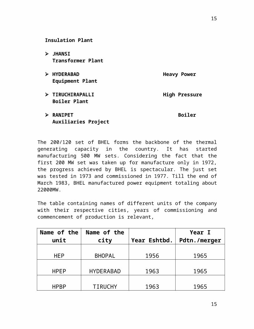
Insulation Plant
JHANSI Transformer Plant
HYDERABAD Heavy Power Equipment Plant
TIRUCHIRAPALLI High Pressure Boiler Plant
RANIPET Boiler Auxiliaries Project
10
10
The 200/120 set of BHEL forms the backbone of the thermal generating capacity in the country. It has started manufacturing 500 MW sets. Considering the fact that the first 200 MW set was taken up for manufacture only in 1972, the progress achieved by BHEL is spectacular. The just set was tested in 1973 and commissioned in 1977. Till the end of March 1983, BHEL manufactured power equipment totaling about 22000MW.
The table containing names of different units of the company with their respective cities, years of commissioning and commencement of production is relevant,
Name of the unit Name of the city Year Eshtbd.
Year I Pdtn./merger
HEP BHOPAL 1956 1965
HPEP HYDERABAD 1963 1965
HPBP TIRUCHY 1963 1965
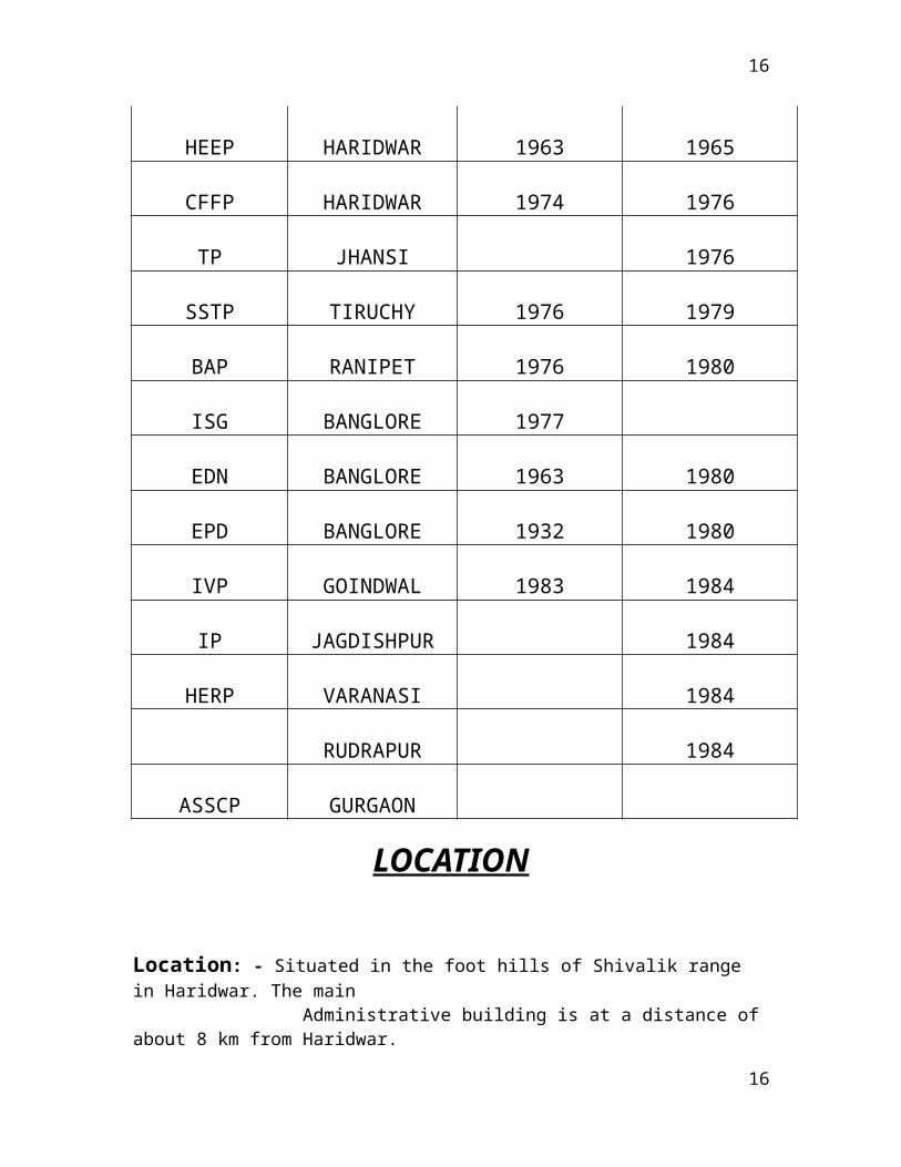
HEEP HARIDWAR 1963 1965
CFFP HARIDWAR 1974 1976
TP JHANSI 1976
SSTP TIRUCHY 1976 1979
BAP RANIPET 1976 1980
ISG BANGLORE 1977
EDN BANGLORE 1963 1980
EPD BANGLORE 1932 1980
IVP GOINDWAL 1983 1984
IP JAGDISHPUR 1984
11
11

HERP VARANASI 1984
RUDRAPUR 1984
ASSCP GURGAON
LOCATION
Location: - Situated in the foot hills of Shivalik range in Haridwar. The main Administrative building is at a distance of about 8 km from Haridwar.
Address: - Bharat Heavy Electrical Limited Ranipur, Haridwar PIN 249403
Area: - BHEL Haridwar consists of two manufacturing units, namely Heavy Electrical Equipment Plant (HEEP) and Central Foundry Forge Plant (CFFP), having area HEEP: 845 sq. km CFFP: 1.0 sq. km
The HEEP, CFFP plant & PCRI are located at Ranipur near the Holy Ganges City HARDWAR on the one side & the picturesque Shivalik foothills on the other side of it. It is about 200 Kms. to the north of New Delhi.
A paradise for nature-lovers, Haridwar presents kaleidoscope of Indian culture and civilization. Haridwar also termed as 'Gateway to Gods' is known as Mayapuri, Kapila, and Gangadwar as well. The followers of Lord Shiva (Har) and followers of Lord Vishnu (Hari) pronounce this place Hardwar and Haridwar respectively as told by some. It is also a point of entry to Dev Bhoomi and Chaar Dham (Four main centers of pilgrimage in Uttaranchal) Viz. Badrinath, Kedarnath, Gangotri and Yamunotri. Archaeological finding have proved that terracotta culture dating between 1700 B.C. and 1200 B.C. existed in this region. Legendary king Bhagirath is said to have brought the river Ganga from heaven to earth in order to provide salvation to his ancestors. It is also said that Haridwar has been sanctified by the presence of three Gods; Brahma, Vishnu and Mahesh. Lord Vishnu is said to have his foot print on the stone that is set in the upper wall of Har-Ki-Pauri where the Holy Ganga touches it all the times. Devout
12
12

believers feel that they can go to heaven by getting their salvation after a dip in the sacred Ganga at Haridwar.
Haridwar is also one of the four places; where Kumbh Mela occurs after rotation of every twelve Years and Ardh Kumbh after every six years. It is said that drops of Amrit (Elixir) fell in to the Brahmkund of Har-Ki-Pairi, therefore considered that a dip in the Brahmakund on this particular day which is very auspicious and when Jupiter (Brahaspati) comes to the sign Aquarius (Kumbh) once in every twelve years the Maha Kumbh fair is celebrated at Haridwar. Kumbh, 1998 was the last Maha Kumbh of this century. Yet beyond the mystic aura and mythology, Haridwar casts another magic spell on the visitor. Being one of the oldest living cities, Haridwar finds its mention in the ancient Hindu scriptures as it waves through the life and time stretching from the period of the Buddha to the more recent British advent. Haridwar has not only remained the abode of the weary in body, mind and spirit, but also served as centre of attraction for many, for learning the arts science and culture. Haridwar's long standing position as a great source for Ayurvedic medicines and herbal remedies as well as its unique Gurukul school of traditional education, the scenic beauty and lush greenery...all give the city unique flavors and charm; a must among the sojourn centers in a discoverer's intinary of Uttaranchal - A destination for all seasons.
Haridwar is one of the first towns where Ganga emerges from the mountains to touch the planes. And that's why the water is crystal clear and cool. Lush green forests and small ponds add to the scenic beauty of this holy land. The Rajaji National Park is just 10 kms from Haridwar. Its an ideal destination for wild life and adventure lovers. In the evening the ghats look breathtakingly beautiful as thousands of diyas (lamps) and marigold flowers float and illuminate the holy waters.
Haridwar as today has not only religious importance but it has another temple of modern civilization i.e. BHEL, a ’Navratna PSU' to its credit. The Roorkee University at Roorkee is one of the oldest and prestigious institutes of learning in the fields of science and engineering. Another university of the district i.e. Gurukul having vast campus is giving traditional educations of its own kind.
Haridwar district, covering a vast landscape is in the western part of Uttaranchal state of India. Its latitude and longitude are 29.00 degree north and 78.58 degree east respectively. The height from the sea level is 249.7 m. The district came into existence on 28thDec. 1988. Prior to its inclusion in the newly created state of Uttaranchal, this district was a part of Saharanpur Divisional Commissionary. The district is ringed by Saharanpur in the west, Dehradun in the north and east, Pauri Garhwal in the east, Muzzaffar Nagar and Bijnor in the south. The district headquarter is situated in the Roshnabad, at a distance of about 12 kms from railway station. The Collectorate, Vikas Bhawan, District Judiciary, S.S.P. Office, Police line, District Jail, District sports stadium, Jawahar Navodaya Vidyalaya etc. are the prime establishments of this area. The district is administratively subdivided into three tehsils i.e. Haridwar, Roorkee and Laksar and six development blocks i.e. Bhagwanpur, Roorkee, Narsan, Bahadrabad, Laksar and Khanpur. Haridwar is one of the first towns where Ganga emerges from the mountains to
13
13

touch the planes. As per the 2001 census, the population of the district is 14, 44,213. Due to Haridwar's location on the bank of river Ganga, it has plenty of water resources and almost all kind of food grains are produced here in abundance. For more statistical details, you may see 'District at a glance' on this web site.
BHEL, HARIDWAR
Bharat Heavy Electricals Limited (BHEL) in Haridwar is known the world over. Situated in the valley of the picturesque Sivalik ranges of the Himalayas, on the banks of Ganga, Haridwar has always been a place of religious significance. The first Prime Minister of independent India, Pt. Jawaharlal Nehru, established the “Heavy Electrical Equipment Limited” in Haridwar in 1961. Production at BHEL commenced in January 1967. Today, 50 countries, including the USA, Russia, Australia and New Zealand, are buyers of BHEL’s products.To ensure ample supply of electricity- the key to national industrial development, the ‘Heavy Electrics India Limited’ was established and its first factory was established in Bhopal. Later such projects of heavy electric equipments were planned in Haridwar, Trichinapalli and Hyderabad. It was under this project that the ‘Heavy Electrical Equipment Plant’ Haridwar was established in 1961. As a result of the expansion of the project, a new corporation was established on 14th November, 1964 named ‘Bharat Heavy Electrical Limited’. It was granted governance of all the three new projects. Production started in January 1967 in the factory of Haridwar. BHEL collaborated with ‘Kraftswork Union’ of West Germany to design, manufacture, install and commission high capacity steam turbines and turbo generators based on A.K.W. technology. BHEL then collaborated with Siemens in 1989 to manufacture advanced large gas turbines of advanced techniques in the field of power. The Haridwar plant also successfully accomplished the orders of 235 MW steam generators and 500 MW steam turbines and generators. The Haridwar plant has manufactured about 130 thermal sets which are installed in various thermal power stations across the country which form the backbone of India’s power generation capability. BHEL is the largest engineering and manufacturing enterprise in India in the energy-related/infrastructure sector today. Establishment of BHEL ushered in the indigenous Heavy Electrical Equipment industry in India - a dream that has been more than realized with a well-recognized track record of performance. The company has been earning profits continuously since 1971-72 and paying dividends since 1976-77. BHEL manufactures over 180 products under 30 major product groups and caters to core sectors of the Indian Economy viz., Power Generation & Transmission, Industry, Transportation, Telecommunication, Renewable Energy, etc. The wide network of
14
14
BHEL's 14 manufacturing divisions, four Power Sector regional centers, over 100 project sites, eight service centers and 18 regional offices, enables the Company to promptly serve its customers and provide them with suitable products, systems and services -- efficiently and at competitive prices. The high level of quality & reliability of its products is due to the emphasis on design, engineering and manufacturing to international standards by acquiring and adapting some of the best technologies from leading companies in the world, together with technologies developed in its own R&D centers.As a result of incessant and extensive innovation, this plant has become one of the main manufactures of hydro sets. It has facilities of engineering and manufacturing Kaplan, Francis, Palten and reversible hydro sets. To remain competitive and meet customers' expectations, BHEL lays great emphasis on the continuous up gradation of products and related technologies, and development of new products. BHEL's commitment to advancement of technology is reflected in its involvement in the development of futuristic technologies like fuel cells and superconducting generators. BHEL's investment in R&D is amongst the largest in the corporate sector in India. A sophisticated and modern hydro turbine research center provides facilities of model construction and research in metal engineering, design and turbine model.
For the treatment of cancer, the Haridwar plant manufactured a 4 M-I-V Linear Accelerator and established a new record in the field of production of medical treatment devices. Initially these types of hi-tech, microwave based products were only being manufactured in U.S.A., Germany, Holland, Japan and France. BHEL Haridwar has also entered into the field of aircrafts manufacturing. In the first phase, two light weight passenger aircrafts named ‘Swati’ were constructed.
15
15
COMPANY’S VISION, MISSION AND
VALUES
VISION A world –Class Engineering Enterprise Committed to
Enhancing Stakeholder Valve.
MISSION To be an Indian Multinational Engineering Enterprise
providing Total Business Solution through Quality
Products, Systems and Services in the field of Energy,
Industry, Transportation, Infrastructure and other
potential areas.
VALUES Zeal to Excel and Zest for Change.
Integrity and Fairness in all Matters.
Respect for Dignity and Potential of Individual.
Strict Adherence to Commitments.
16
16
Ensure Speed of Response.
Foster Learning, Creativity and Teamwork.
Loyalty and Pride in the Company.
COLLABORATIONS
The divisions which were firstly established became the foundation for industrial development of India. At that time we were not in a position to establish such plants obviously there were some collaborators for these establishments afterwards we setup units with fully vernacularly developed technologies. Following table is showing it,
Name of the Unit Name of the CityCollaborator (Original)
HEP BHOPAL AEI (UK)
HPEP HYDERABAD SCODA-EXPORTS (USSR)
HPBP TIRUCHY SCODA-EXPORTS (USSR)
17
17
HEEP HARIDWAR PROMMASH-EXPORTS (USSR)
CFFP HARIDWAR CRUESOT LOIRE (FRANCE)
The technological base of BHEL in the area of Steam turbines and Turbo Generators has been created by acquiring technological information from the collaborators.Initially BHEL had collaboration with M/s LMW USSR for 100 and 210 MW sets. In 1976, BHEL entered into technical collaboration agreement with M/s Siemens-KWU, Germany to acquire the know-how and know-why for turbine generator sets up to 1000 MW. This collaboration still continues.This helps BHEL to keep pace with the worldwide technological progress and offer state of the art equipment to it's customer.Under this collaboration agreement, BHEL has established strong design, manufacturing and servicing base for unit up to 500 MW ratings.Afterwards many more collaborations took place as required for different products at different units, the table would be helpful in the context,
Products Collaborations
Thermal sets, hydro sets, motors and control gears
Prommash-ExportsUSSR
Bypass and pressure reducing system
Sulzer Brothers Ltd.Switzerland
Electronic automation systems Siemens AGGermany
Francis type hydro turbines General ElectricCanada
Moisture separator reheaters Baloke duerrGermany
Christmus trees and conventionalwellhead assemblies
National Oil WellUSA
18
18

Steam turbine, generators and Siemens AG
Axial condensers GermanyProducts Collaborations
Gas turbines General Electric Co.USA
Tube mills Stein IndustriesFrance
Dry type transformers May & ChristeGermany
QUALITY CONFORMATION
Quality policy of BHEL says
"TO MAINTAIN A LEADING POSITION AS A SUPPLIER OF QUALITY PRODUCTS, SYSTEMS & SERVICES TO NATIONAL / INTERNATIONAL STANDARDS TO MEET THE REQUIREMENTS OF CUSTOMER"
Quality is in fact a way of life in BHEL. Be it in incoming material, in process, machining, assembly or testing, "Quality" is the watchword. Quality Assurance & Control System, Quality Plans and Field Quality Assurance are aids to total quality concept.As a testimony to excellent quality consciousness in BHEL, BVQI with accreditation from UK, Holland and Germany has certified HEEP Hardwar with the prestigious ISO 9001 for all its products and services.We follow various National/ International standards like IEC, ANSI, ASME, DIN etc. at all the stages of product cycle.
19
19

INTERNATIONAL OPERATIONS
BHARAT HEAVY ELECTRICALS LIMITED has over the years, established its references in over 50 countries of the world, ranging from United States in the west to New Zealand in the far east. These references encompass almost the entire product range of BHARAT HEAVY ELECTRICALS LIMITED, covering turnkey power projects, rehabilitation projects, besides a wide variety of products like switch gear, transformers, heat exchangers, insulators, castings and forgings.
Some of the, major successes achieved by the company have been in Oman, Saudi Arabia, Libya, Greece, Cyprus, Malta, Egypt, Bangladesh, Azerbaijan, Srilanka, Iraq etc. Execution of overseas projects has also provided BHARAT HEAVY ELECTRICALS LIMITED the experience of working with world – renowned consulting organization and inspection agencies. The company has been successful in meeting demanding requirements of both domestic and international markers, in terms of complexity of the works as well as the technological, Quality and requirements viz. Financing package, extended warrantees, associated operations & maintenance etc. The success in area of rehabilitation and life extension of power projects has established BHARAT HEAVY ELECTRICALS LIMITED as a comparable alternative to the original equipment manufacturers for such power plants.
20
20

BUSINESS ACTIVITIES
Business activities of BHEL can be classified as
1. Power sectora. Generationb. Transmission
2. Industriesa. Transportationb. Telecommunicationc. Renewable energyd. Other industries
3. International operations
Power Generation Sector
Power generation sector comprises thermal gases hydro and nuclear power plant business. As of 31-3-2004 BHEL supplied sets account of nearly 71255 MW or 64% of the total installed capacity of 111151 MW in the country as against nil till 1969-70.BHEL has turnkey capabilities for executing power projects from concept to commissioning. It process the technology and capability to produce thermal sets with super critical parameters up to 1000MW unit rating and gas turbine generator sets of up to 250 MW unit rating. Cogeneration and combined cycle plants have been introduced to achieve higher plant efficiencies. To make efficient use of high ash content coal available in India, BHEL supplies circulating fluidized bed combustion boiler to both thermal and combined cycle power plants.
21
21

The company manufactures 235 MW Nuclear turbine generator sets and has commenced production of 500 MW nuclear turbine generator sets.Custom-made hydro sets of Fransis, Pelton, Kaplan types for different head discharge combinations are also engineered and manufactured by BHEL. In all, orders for more than 700 utility sets of thermal, hydro, gas and nuclear have been placed on the company as on date. The power plant equipment manufactured by BHEL is based on the contemporary technology comparable to the best in the world, and is also internationally competitive.The company has proven expertise in plant performance improvement through renovation, modernization and up rating of a variety of power plant equipment, beside specialized know-how of residual life assessment, health diagnostics and life extensions of plants.
Power Transmission
BHEL also supplies a wide range of transmission and systems of up to 400 kV class. These include high- voltage power and instrument transformers, shunt and series reactors, SF switch gear, 33 kV gas insulated sub-station capacitors, insulators etc. For economic transmission of bulk power over long distances, high voltage direct current systems are supplied. Series and shunt compensation systems, to minimize transmissions losses, have also been supplied.
Transportation
Most of the trains operated by Indian railways including the metros in Calcutta are equipped with BHEL’s traction electric and traction control equipment. The company supplies electric locomotives to Indian railways and diesel shunting locomotives to various industries. 5000/4600 hp AC/DC locomotives developed and manufactured by BHEL have been supplied to Indian railways. Battery powered road vehicles are also manufactured by the company. BHEL also supplies traction electrics and traction control equipment for electric locos, diesel electric locos, EMUs and DEMUs to the railways.
Renewable Energy
Technologies that can be offered by BHEL for exploiting non conventional and renewable sources of energy include wind electric generators, solar power based water pump, lighting and heating systems.
22
22

The company manufactures wind electric generators of unit size up to 250 kW for wind forms, to meet the growing demand for harnessing wind energy.
Other Industries
BHEL is a major contributor of equipment and systems to industries such as CementSugarFertilizerRefineriesPetrochemicalsSteelPaper etc.
The range of systems and equipments supplied includes captive power plants, DG power plants, high speed industrial drive turbines, industrial boilers and auxiliaries, waste heat recovery boilers, gas turbines, heat exchangers and pressure vessels centrifugal compressors, electrical machines, pumps, valves, seamless steel tubes and process controls.Control system for process industries and control & instrumentation systems for power plant for power plants, defense and other applications.The company has commenced manufacture of large desalination plants to help augment the supply of drinking water to people.
23
23

MANUFACTURING FACILITIES
HEEP Hardwar plant is equipped with most modern and sophisticated machine tools, facilities and test equipment to manufacture and test generators up to 1000 MW rating, which include:
Most modern micalastic insulation plant for stator bars Overspeed and vacuum balancing tunnel
24
24

Koellmann rotor slot milling machine up to maximum barrel length of 7000 mm, barrel dia. of 1800 mm and rotor weight of 225 tons
Two computerized test beds to test large size generators up to 1000 MW Wotan CNC horizontal boring machine Center lathe machine up to max. length of 16 m and dia. of 3.15 m Insulation life endurance test assessment facility
Besides these, HEEP has also set up a Generator Research Institute with an objective to develop basic know-how and know-why through experimental studies for reliable, efficient and optimum design of generators and improve their performance in service.
CLASSIFICATION OF PRODUCTS
According to industries to which they are meant to, classification of the products can be done as follows: -
Power generation and transmission
Steam turbine-generator sets & auxiliaries
25
25

Boiler and boiler auxiliariesOnce-through boilersNuclear power generation equipmentHydro turbine generator sets and auxiliaries Mini/Micro Hydro Generator Sets Gas Turbine Generator Sets Waste Heat Recovery Boilers Heat Exchangers Condensers Bowl Mills and Tube Mills Gravimetric Feeders Regenerative Air Free Heaters Electrostatic Precipitators Bag Filters Valves Pumps Electrical Machines Piping Systems
Power Distribution
Synchronous Condensers Switchgear Control gear Distributed Digital Control for Power Stations Bus Ducts Rectifiers Porcelain Insulators Ceralin
System & Services
Turnkey Utility Power Stations/ Epc Contracts Captive Power Plants Cogeneration Systems Combined Cycle Power Plants Modernization & Renovation Of Power Stations RLA Studies Switchyards and Substations HVDC Transmission Systems Shunt and Series Compensation SystemsPower System Analysis Eraction, Commissioning & Operations Consultancy & Construction Services
Industries
26
26

Steam Turbine Generator Sets Gas Turbine Generator Sets Diesel Engine Based Generators Industrial System Generators Heat Recovery Steam Generators Fluid Bed Combustion Boilers Drive & Marine Turbines Industrial Heat Exchangers Centrifugal Compressors Industrial Valves Reactors Columns Pressure Vessels Pumps Industrial Fans Seamless Steel Tubes Fabric Filters Ac/Dc Motors Variable Speed Ac Drives Electronic Control gear and Automation
Equipment
DDC for Process Industries Thyrister Equipment Power Devices Energy Meters Transformers Switchgear Insulators Capacitors Broad Gauge AC / DC Locomotives Diesel Electric Shunting Locomotives Traction Motors and Control Equipment Electric Trolley Buses Ac/Dc Electric Multiple Units Drives and Controls for Metro Systems Battery Operated Passenger Vans Oil Rigs and Oil Field Equipment Digital Switching Systems X-Mas Trees and Well Heads Cathodic Protection Equipment Rural Automatic Exchange Simulators Wind Electric Generators
27
27

Solar Powered Water Pumps Solar Water Heating Systems Photo Voltaic Systems Defense Equipments
OBJECTIVES
To plan the manpower requirement & budget the human resources with necessary qualification, skills, aptitude, merit & suitability in accordance with the organizational requirements.
To ensure that the company attracts & retains the best of personnel in each of the areas of functioning.
28
28
To focus on placement of employees in the job to which they are best fitted. To adapt to & fulfill the socioeconomic commitment of the govt. to the
unfortunate/minority sections. To systematically build up a model system for the guidance of & emulation by other
enterprises both in the public & private sectors.
Personnel (OE & Policy) Personnel (E & C / IR) Operation cell Welfare Canteen General Administration cell / legal Law Recruitment cell Liaison cell Manpower Planning
Heavy Electrical Equipment Plant (HEEP),
Haridwar
Heavy Electrical Equipment Plant, Haridwar is one of the major manufacturing units of BHEL. It has achieved an all time high turnover of Rs. 1641 crores in 2005 – 2006. The
29
29

210, 250 and 500 MW thermal sets, made by HEEP, constitute 65% of total thermal coal based power plants. These contribute to 71 % of total generated by coal based thermal sets in the country. HEEP shares in the total installed capacity of the nation have continuously grown over the years. In 2005 – 06 HEEP added 1250 MW to national grid and 312 MW added in Libya by exports. Product profile of HEEP consists of 91.5 % share of turnover as thermal, gas and nuclear turbine generator sets and rest as hydro turbine generator sets, AC motors and SRGM guns for defense. HEEP customer profile ranges from State Electricity Boards, Government; power utilities like NTPC, NPC, NHPC to IPP’s like Reliance Energy. HEEP has also exported gas turbine sets to Libya and Iraq. PS regions of BHEL are its key internal costumers. The key costumer NTPC has drawn up plans for capacity addition of 17000 MW by 2012. HEEP has planned for execution of 34,619 MW by 2012. to meet the emerging challenges the focus is given on increasing manufacturing capacity and introduction of new technologies (300/ 350/ 800 MW thermal sets). It helped HEEP to maintain its leading position in the domestic market. HEEP obtained orders worth Rs. 1484 crores in 2005 – 06 taking total order book to record Rs. 3869 crores. To meet the 11 th 5 – year plan target of adding 62529 MW, CEA has planned addition of 23 nos. standard 500 MW sets for faster project execution and cost reduction. HEEP is a part of this process. HEEP is strategically concentrate on higher rating coal based thermal sets to fulfill the country’s vision of adding 107,000 MW capacity to achieve “Power on Demand” by 2012. Much before the manufacturing of the first electrical machine at HEEP BHEL Haridwar, the HRD Centre was established in the year 1963. known as Technical training School in the yesteryears, the foundation stone of HRD was laid on 17th July 1963 by the then Chief Minister of Uttar Pradesh, Late Shri C.B.Gupta. The Technical Training School of 1963 became popular as Training School in the later years. In fact the campus and building of HRD was the first to be built in BHEL Township. The earlier years saw training of first batch of artisans and engineers in the erstwhile ‘Technical Training School’. The Centre was utilized for large scales fabrication activity, which helped the erection of Heavy Electrical Equipment Plant.
Over a period of 36 long years spanning more than three decades, the center has grown both in its field of activities and magnitude of efforts made to develop human resource. Initially the objective was solely training of artisans who were to man the plant of HEEP. Skill training in the various trades relevant to the plant was indeed the primary goal. The scope and function of the Centre later expanded to include training of supervisors, engineers and managers. The growth of Center kept pace with the demands of changing technology and complexities of management due to ever changing environment conditions.
PRODUCT PROFILE OF HEEP
Sr.No. PRODUCT RANGE
Thermal sets Steam Turbines & Turbo Generators
30
30

1.
2.
3.
4.
5.
6.
7.
8.
9.
Hydro sets
Gas Turbines Combined Cycle Power Plant.
Electrical Machines.
Medical equipment.
Equipment for Nuclear Power Plant.
Control Panel.
Aviation.
Defense equipment.
of unit size up to 1000 MW.
Custom-built conventional Hydro Turbine of Kaplan, Francis & Pelton with matching generators up to 250 MW unit size.
60,150 & 200 MW.ISO Ratings.
With Steam Turbines up to 300 MW.
Medium & Large sized AC/DC Electrical Machines various capacities up to 20MW
4-6 MeV Linac Accelerator Machine for treatment of cancer.
Turbines & generators up to 500MW
Steam generator up to 500MW unit size, Reheaters/Separators, Heat exchangers & pressure vessels.
Control panel for voltage up to 400 kW & control desks for generating stations & EMV sub-stations.
Light aircraft namely “SWATI.
Naval guns with collaboration of Italy.
At present nearly 37% of the country’s electrical energy is generated from the sets manufactured by BHEL, Hardwar. Foundry Forging Plant (CFFP) is located.
31
31
PRODUCT PROFILE OF CFFP
Sr.No. PRODUCT RANGE
1.
2.
3.
4.
Steel castings.
Steel forging shafts.
Rings.
Discs.
Up to 50 T/pc.wt.
Cast weld up to 80T/pc.wt.
Up to 55T/pc.wt.
Max. Dia 2000 mm.
Length – 14m.
Max. Dia 3000mm.
Thickness- 3800mm.
Max. Dia. 3500mm.
Thickness-variable.
32
32

Description of 8 Blocks
33
33

CHART SHOWING THE DIFFERENT BLOCKS OF B.H.E.L, HARDWAR
34
34
BHARAT HEAVY ELECTRICALS LTD.
HARDWAR
HARDWAR
HEEP (HEAVYEL ECTRICALEQUIPMENT PLANT)
CFFP (CENTRAL FOUNDARYFORGED PLANT)
BLOCK-2: HEAVY FABRICATION SHOP
BLOCK-3: TURBINE MANUFACTURING BLOCK
BLOCK-4: CIM (COILS & INSULATION MANU- FACTURING) BLOCK
BLOCK-5: CONDENCER FABRICATION & FORGR BLOCK
BLOCK-6: FABRICATION SHOP, DIE SHOP,STAMPING SHOP)
BLOCK-7: CARPANTARY SHOP
BLOCK-8: HEAT EXCHANGER SHOP
BLOCK-1: ELECTRICAL MACHINE SHOP

DESCRIPTION OF 8 BLOCKS OF HEEP
BLOCK-1 This is the main block of HEEP named as Electrical Machine Shop. The main products of this block –1 are turbo generators, hydro generators & AC and DC motors. In this block there are 3 bays which are known as HMS (Heavy Machine Shop).In this shop all components of generators & motors are manufactured on different machines such as Lathes, vertical & horizontal boring machines and vertical & horizontal milling machines. There is also one important dept. OBI (Over speed Balancing Installation) in which balancing of Rotors of generators & motors is carried out. Winding of generators & motors is also done.
VIEW OF BLOCK - 1
OUTER CASING OF HYDRO GENERATOR
35
35

Some of the important machines of block 1 are as shown ahead: -
SKODA LATHE MACHINE WALDRICH CNC SLOT CUTTING M/C
BLOCK-2 This is a Heavy Fabrication Shop in which fabrication of all type of parts of turbines as well as generators are done. In which internal and external casing of turbines and generators fabricated. In this block Hollow and Solid Blades of Steam Turbines are welded on a disk which is fitted on the rotor.
In this block work is divided into four steps namely Bay-1, Bay-2, Bay-3, and Bay-4.In Bay-1 Preparatory work is been done i.e. cutting, shaping, grinding, pressing etc. In Bay –2 & Bay-3 assembly work is done. Bay-4 is called HMS (Heavy Machine Shop) in which all types of components of turbine, generators and motors are manufactured. In Bay-4 small Heat Exchanger are also manufactured which is used in turbines for cooling purpose. A Small Sheet Metal Shop is also a part of this Block. A gentry shop is also a part of this block where raw material is been kept and transported to different bays.
BLOCK-3 This block is called Turbine Manufacturing Block. This block contributes maximum in terms of turnover. Where steam, Gas & Hydro all three types of turbines are manufactured. This Block also divided into 4 Bays. And these bays are further divided into several sections and shops.
BLOCK-- 4 Block-4 is called as CIM (COILS & INSULATION) BLOCK. In this block coils of Generators & motors are made & assembled. Also insulation of all DC & AC motors and Generators are done. The material of coils is copper (Cu), there are small cranes, trolleys, conveyors, & trucks are used for transportation. Coiling & insulation of all motors & Generators of capacity up to 500 MW made in Block-1 are done here with the help of several machines & manpower. Electric control panel & copper bars of turbo generators are also manufactured here. Coiling of motor & generators are done with help of taping operation.
36
36

Block-4 having following two sections: 1. Coil and insulation manufacturing section2. Advanced control gear manufacturing section
BLOCK-5 Block-5 is called as CONDENSER FABRICATION & FORGE BLOCKAll type of condenser used for refrigeration purpose in turbines are fabricated here. This block is small as compare to Block-2. In these block different types of machines like Submerged arc Welding machine, Planer machine, CNC milling machines, grinding machine etc are used for fabricated the condensers.
BLOCK-6 Block –6 is divided into 3 parts Fabrication shop, Die shop, Stamping shop.
Block-7 This Block is called as CARPENTRY SHOP. In this Block all carpentry work is done such as making of wood pattern for casting purpose, making of fixtures. Large wood container used for packing of several jobs like different components of Turbines, Generators, motors etc.
Block-8 This is the last block of Heavy Electrical Equipment Plant (HEEP) named as HEAT EXCHANGER SHOP. In this Block all type of Heat Exchanger of Steam turbines are manufactured. This block also manufactures pressure vessels. In this block work is done with help of several machines like submerged arc welding, Vertical & Horizontal Boring machine etc.
37
37

BLOCK 3 – TURBINE BLOCK
38
38

DESCRIPTION OF BLOCK WITH MACHINES
Bay 1 Bay 2 Bay 3 Bay 4Heavy Machine Shop (Turbine & Its component manufacturing)
Turbine Governing Assembly
Tool room Old Blade shop
HorizontalBoring M/C
HP, IP, Turbine Assly.
Operating Valves for Steam Flow Control
Standard (ISO based) tools.
Manufacturing of Old Design Blades
Special purpose tools – Jigs & FixturesAbout 70000 tooling in turbine assly.
CNC Vertical Boring
LP Rotor Assly. Ist
Generation Blades (Late 1970’s)
2nd Generation blades (Late 1980’s)
Ram Borers LP Casting Manufacturing
Nozzle & Throttle Control Governing Systems
T2 Profile Blades
T4 Profile Blades
Band Saw M/C
Cylindrical Profile
Cylindrical Profile
Deep hole drilling M/C
1% of Gain in stage efficiency over T2 Profile.
Manufacturing of LP free standing blades by employing modern processes in TBM
39
39

SALIENT FEATURES
1: MANUFACTURING CAPABILITIES
Capability to manufacture three types of stem turbines
For fossil fuel power plant (HP, LP, IP) – 1000MW
For nuclear power plants – 500MW
For combined cycle power plants – 300MW
Two types of designs are broadly manufactured
LMW (Lenning metal works), Russian design
KWU (Kraft works union) design
Modular turbine design concept
HP & IP Casing has double shell construction & LP has three shell
construction.
HP outer casing barrel type construction.
IP turbine with single or double flow type.
Turbine with nozzle /throttle governing system.
Turbine suitable for constant pressure as well as sliding pressure operation
along with base load operation.
2. OPERATIONAL FACILITIES
Hollow guide blade with suction slits for moisture removal in last LP stage.
Pedestal bearings isolated from turbine casing.
Combined stop & control valves with servomotor control individually.
Hybrid burner for gas turbine
E – ring for gas turbine.
Deep hole drilling in HP outer casing supplied by M/S CFFP.
KOMET drilling machine for joint plane drilling of casing & LP rotor.
Ram borer machine for fir – tree-grooving operation.
OSBT for rotors up to 1300MW unit size ST/TG.
CNC lathe machining of valve covers & yokes.
40
40

Vertical band saw machine for joint plane slitting of turbine casing.
Special facing & boring Head for CNC horizontal borer for deep boring in IV
& CV.
GAS TURBINE
41
41

STEAM TURBINE
GENERAL DESCRIPTION
The turbine is condensing, tandem compound, three cylinder, horizontal disc and
diaphragm type with nozzle governing and regenerative feed water heating. The double
flow L.P. turbine incorporates a multi exhaust in each flow.
The complete assembly is mounted on a pedestals and sole plates, which are designed to
ensure that the components are free to expand whilst correct alignment is maintained
under all conditions. Live steam from the boiler enters in two emergency stop valves
(ESV) of high pressure turbines. From ESV steam flows to the four control valves (CV)
mounted on the casing of high pressure turbine (HPT) at the middle bearing side. Control
valves in turn feed the steam to nozzle boxes located inside the HPT.
42
42

The high pressure turbine comprises of 12 stages, the first stage being governing stage.
The steam flow in HPT being in reverse direction, the blades in HPT are designed for
anticlockwise rotation, when viewed in the direction of steam flow.
After passing through H.P. turbine steam flows to boiler for reheating and reheated steam
comes to the intermediate pressure turbine (IPT) through two Interceptor valves (IV) and
flow control valves (CV) mounted on the IPT itself.
The intermediate pressure turbine has 11 stages. H.P. and I.P. rotors are connected by
rigid coupling and have a common bearing.
After flowing through IPT, steam enters the middle part of low pressure turbine,(LPT)
through two cross over pipes. In LP turbine, steam flows in opposite path having four
stages in each part. After leaving the L.P. turbine, the exhaust steam condenses in the
surface condensers welded directly to the exhaust part of the L.P. turbine.
Rotors of intermediate and low pressure turbine are connected by a semi flexible
coupling.
The direction of the rotation of the rotors is clockwise when viewed from the front
bearing end towards the generator. The three rotors are supported on five bearings. The
common bearing of H.P. and I.P. rotors is a combined journal and radial thrust bearing.
The anchor point of the turbine is located at the middle foundation frame of the
front exhaust part of low pressure cylinder. The turbine expands towards the front bearing
by nearly 30 mm and towards generator by 3 mm in steady state operation at full load
with rated parameters.
Turbine is equipped with turning gear which rotates the rotor of the turbine at a
speed of nearly 3.4 r.p.m. for providing uniform heating during starting and uniform
cooling during shut down.
In order to heat the feed water in the regenerative cycle of the turbine, condensate
from the hot well of condenser is pumped by the condensate pumps, and supplied to the
deaerators through ejectors, gland steam coolers, L.P. heaters and gland cooler. From
deaerator, the feed water is supplied to boiler by boiler feed pumps through H.P. heaters.
Extracted steam from the various points of the turbine is utilized to heat the condensate.
43
43

HP TURBINE The outer casing of the HP turbine is of barrel type construction without any massive
horizontal flange. This unique construction permits rapid start-up from any thermal state
and high rates of load changes of the turboset. The steam and metal temperature matching
requirements are also less stringent as there is no asymmetry of mass distribution in
transverse or longitudinal planes.
Although HP inner casing is with a horizontal split joint, yet it represents itself like a thin
thermal membrane. As the inner casing is not subjected to large pressure differentials, the
horizontal flange joint and bolts are made of thin sections thus permitting large transverse
temperature hanges. Inner casing is kinematically supported within the outer barrel.
For overhauls and capital maintenance of barrel type HP outer casing , handling
fixtures are supplied along with turbine which enable the disassembly and assembly of
HP turbine in a short time.
44
44

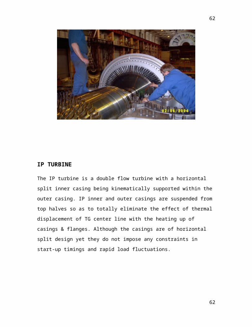
IP TURBINE The IP turbine is a double flow turbine with a horizontal split inner casing being
kinematically supported within the outer casing. IP inner and outer casings are suspended
from top halves so as to totally eliminate the effect of thermal displacement of TG center
line with the heating up of casings & flanges. Although the casings are of horizontal split
design yet they do not impose any constraints in start-up timings and rapid load
fluctuations.
45
45

46
46

LP TURBINE LP Turbine is a double flow type with exhaust area optimally selected for the expected
vacuum conditions. The casing of LP turbine is connected with IP cylinder by two cross
around pipes, one on either side of the machine and level with the floor. The horizontally
split, fabricated LP casing is of three shell construction.
Special design measures have been adopted to remove the moisture from last stages by
reducing the thickness of water film on guide blades. The axial clearances between guide
and moving blades have been so chosen as to reduce the droplet sizes and resulting
erosion of leading edges. Low pressure extraction has been optimized not only from
thermodynamic considerations but to effectively drain out moisture also. Free standing
blades have been envisaged for the last three stages. The blades are designed to operate
the machine continuously within frequency range from 47.5 to 51.5 Hz.
47
47

48
48

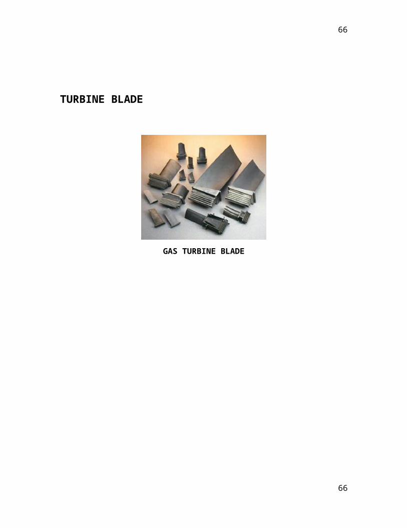
TURBINE BLADE
GAS TURBINE BLADE
49
49

Cylindrical reaction blades for HP, IP and LP Turbines
3-DS blades, in initial stages of HP and IP Turbine, to reduce secondary losses
Twisted blade with integral shroud, in last stages of HP, IP and initial stages of LP
turbines, to reduce profile and Tip leakage losses
Free standing LP moving blades
Tip sections with supersonic design
Fir-tree root
Flame hardening of the leading edge
Banana type hollow guide blade
Tapered and forward leaning for optimized mass flow distribution
Suction slits for moisture removal
Classification of Blades
L.P. Moving Blade Forged Ist Stage.
L.P. Moving Blade 500 MW Last Stage.
100 MW 25th Stage Impulse Blade.
Compressor blade Sermental coated.
Compressor Blade 'O' stage.
Gas Turbine Compressor Blade.
T-2 Blade.
T-4 Blade.
3DS Blade.
Brazed Blade
50
50

Russian Design Blades.
Z – Shroud Blade.
Twisted Blade.
Present Range of Blades.
Future Range of Blades.
ROTORS
1. High Pressure Rotor
The HP rotor is machined from a single Cr-Mo-V steel forging with integral discs. The
rotor forging is thermally stabilized to prevent abnormal deflection. The blades are
attached to their respective wheels by ‘T’ root fastening.
In all the moving wheels, balancing holes are machined to reduce the pressure
difference across them, which results in reduction of axial thrust. First stage has integral
shrouds while other rows have shrouding, riveted to the blades at periphery. The number
of blades connected by a single strip of shrouding is called a blade packet and the number
of blades per packet is decided from vibration point of view.
2. Intermediate Pressure Rotor
The IP rotor has seven discs integrally forged with rotor while last four discs are shrunk
fit. The shaft is made of high creep resisting Cr-Mo-V steel forging while the shrunk fit
discs fit discs are machined from high strength nickel steel forgings.
The blades on the integral discs are secured by ‘T’ root fastenings while on
shrunk fit discs by ‘fork root’ fastening. Except the last two wheels, all other wheels have
shrouding riveted at the tip of the blades. To adjust the frequency of the moving blades,
lacing wires have been provided in some stages.
3. Low Pressure Rotor
51
51

The LP Rotor consists of shrunk fit discs on a shaft. The shaft is a forging of Cr-Mo-V
steel while the discs are of high strength nickel steel forgings.
Blades are secured to the respective discs by riveted fork foot fastening. In all the stages
lacing wires are provided to adjust the frequency of the blades.
In the last two rows satellites strips are provided at the leading edges of the blades to
protect them against wet steam erosion.
52
52

Technology used by bhel Haridwar for balancing of rotors
OVER SPEED VACUUM BALANCING TUNNEL (OSBT)
SALIENT FEATURES OF OSBT
Rotor weight: 320MT maxRotor Diameter: 6990mm maxRotor Journal: 950mm maxBalancing Speed: 3600rpm maxOver speeding range: 2500-4500rpm maxVacuum: 2torrTunnel Length: 19000mm maxTunnel Diameter: 9000mm maxTunnel Thickness: 32mmDistance between- 7500mm maxpedestal bearings:Tunnel Wall Thickness: 2500mm
53
53

BALANCING PROCEDURE FOR THE ROTORS
The present procedure which is being followed at BHEL is covering various turbine rotors in the range of 200-1000MW rating and required to be at rated speed. This includes both rigid and flexible rotors. The procedure outlines the sequence and description of the operation which are to be performed to accomplish the process of balancing and over speeding of the turbine rotors.
RIGID ROTORS
A rotor is considered rigid when it can be corrected in any two (arbitrarily selected) planes and after these corrections; it’s unbalanced does not significantly exceed the balancing limits or tolerances (relative to the shaft axis) at any speed upto maximum service speed when running under condition approximately close to those of the final supporting system.
FLEXIBLE ROTORS
The rotor not specifying the definition of rigid rotors is flexible rotor due to elastic definition.
According to the ISO definition balancing is the procedure by which the mass distribution of the rotor is checked and if necessary is adjusted in order to ensure that the vibrations on the supporting bearings at a frequency corresponding to the operation within the specified limits. This is done to avoid damage to bearings, housings and foundation and to minimize the fatigue stresses on the rotor.
Balancing is carried out by consecutive compensation below and above critical speed and its rated speed to bring down the vibration within the specified limits. According to the check list provided by quality control department should be strictly followed for trouble free balancing.
54
54

BRIEF LAYOUT OF THE ROTORS
The rotors are assembled on the bogie pedestals and it is then driven into the over speed and balancing tunnel which can be evacuated to a high degree of vacuum upto 2 torr depending upon the requirement. Vibrations are picked up through electromagnetic pickups mounted on the pedestals and the readings are displayed on the instruments installed in the control room. The intelligence about various parameters e.g. vibrations bearing temperature, tunnel temperature etc. are carried out to the instruments installed in the control room through cables passing through special vacuum penetration system located in the rear wall of the tunnel. Access to the rotor is provided through a main door in the rear wall of the tunnel while the rotor is in standstill condition. The rotor is driven through a drive system consisting of two D.C. motors of 3.5MW each connected in tandem. The speed of the motor can be regulated from 2 rpm to 500 rpm and of rotor from 10 rpm to 4450 rpm. The power to the motor is fed through a MG set consisting of a 9MW synchronous motor and two D.C. generator of 4MW each.
There are two lubrication systems- atmospheric oil system providing oil to MG set and drive system and vacuum oil system providing oil to the rotor bearing housed balancing pedestals in the tunnel and the oil is water cooled.
ASSEMBLY OF ROTORS
The distance of bogie pedestals is adjusted as per the supporting journal to journal centre line distance of the rotor. The continuity of the bearing should be checked by the quality control engineer before these are mounted in pedestals. The rotors are then placed in the balancing machine pedestals with special lifting tackles and the assembly is done as per relevant assembly drawings. Care must be taken to ensure that the dowel pin of the top cover of both bearings is set in right position. Quality control engineer will check the correctness of the bearings and cover bolts, correctness of installation of RTD’s and their resistances etc.
Quality control engineer will certify that the rotor has been manufactured and assembled according to the relevant drawings and specifications and is fit for balancing and over speeding test.
PREPARATION FOR BALANCING OF ROTOR
55
55
After securing of the pedestals and connection of the rotor with drive system the lubricating oil pipes, jacking oil pipes and drain pipes should be connected. Lubricating oil should be started to the pedestals bearing (to match design requirements) and flushing may be carried out for a couple of hours. During flushing rotor may be jacked few times and rotor lifts at both the pedestals are to be checked by means of dial gauges and the reading noted down. The rotor can be run at about 150 rpm for a few minutes without any vacuum and is observed visually. It should be checked that there is no abnormal sound and no leakage of oil etc. After this the main door near the rear wall should be closed and tunnel gate should be closed and hydraulically pressed against the wall of tunnel. The light of the tunnel and power supply to the tunnel hoist and jib crane should be ‘switched on’. After the requisite vacuum in the tunnel the rotor can be run upto a suitable speed below first critical speed at which vibration does not become excessive.
After correction of unbalance for the first critical speed, it should be possible to increase the rotor speed beyond the first critical speed without subjecting the rotor to any excessive level of vibration at the first critical speed. Rotor should now be ready for 2nd
balancing. The process is continued till we get a low value of vibration at 3000 rpm. Rotor can now be brought to the specified over speed (3360 rpm or 3600 rpm) as the case may be and retained there for two minutes or specified in the technical requirements. The accuracy of the drive system permits the maintenance of speed within ±1% of the set value. After over speeding the rotor is stopped, thoroughly checked for any part of the rotor having becoming loose specially the locking blades lift. These check are made by Q.C. and assembly group and if required the rectification should be carried within the permitted limits. After achieving the vibrations within the permitted limits couple of runs will be carried out to improve the balance quality further if possible. After the balancing is over the position of the weights placed in different correction planes will be noted with reference to the clock punched on the rotor.
EVALUATION OF BALANCING
All the rotors in OSBT are balanced at the rated speed and the evaluation of unbalance is by means of vibrations measurement at the rated speed. The permissible vibrations at the rated speed for rotors are given as follows:-
Rotor at 3000 rpm Vibration velocity Equivalent peak
56
56

in mm/s vibration in µ(microns)
For rotors of all modules of ‘H’ series upto H30-100 and ‘HR’ series upto HR30-63
0.5 4.5
For rotors of all modules of ‘M’ series upto M30-100 and ‘S’ series upto S30-100
0.7 6.3
For rotors of all modules of LP upto N30-2*10
1.0 9.0
Near first critical speed of 1100 rpm LP(N30-2*10)
0.5 12.3
Near the 2nd critical speed of 2600 rpm LP(N30-2*10)
2.0 20.8
MARKING OF ROTOR
57
57

The rotor is marked with Cartesian coordinate system with reference to the marking on the intermediate shaft as shown below:
BALANCING STANDARDS
The various standards followed for evaluation of balancing quality of rotating machine in Steam Turbine and in particular at BHEL is as follows:
APT 512
Special purpose steam turbines for petroleum, chemical and gas industry services.
ISO 1040-1
Mechanical vibrations- balance quality requirements of rigid rotors.
ISO 11342
Mechanical vibrations- method and criteria for the mechanical balance of flexible rotors.
PROJECT ON “GENERAL VIEW OF STEAM TURBINES”
58
58

INTRODUCTION
Coupled steam turbine
A steam turbine is a mechanical device that extracts thermal energy from pressurized steam, and converts it into useful mechanical work. It has almost completely replaced the reciprocating piston steam engine, invented by Thomas Newcomen and greatly improved by James Watt, primarily because of its greater thermal efficiency and higher power-to-weight ratio. Also, because the turbine generates rotary motion, rather than requiring a linkage mechanism to convert reciprocating to rotary motion, it is particularly suited for use driving an electrical generator — about 86% of all electric generation in the world is by use of steam turbines. The steam turbine is a form of heat engine that derives much of its improvement in thermodynamic efficiency from the use of multiple stages in the expansion of the steam, as opposed to the one stage in the Watt engine, which results in a closer approach to the ideal reversible process.
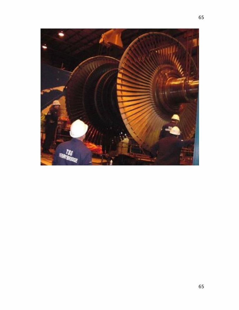
A steam turbine consists of a rotor resting on bearings and enclosed in a cylindrical casing. The rotor is turned by steam impinging against attached vanes or blades on which it exerts a force in the tangential direction. Thus a steam turbine could be viewed as a complex series of windmill-like arrangements, all assembled on the same shaft.
Steam has one great advantage over water—it expands in volume with tremendous velocity, often as much as 4,000 feet (1,200 meters) per second. No wheel made can revolve at any speed approaching this velocity. Various devices, however, are used to subdue the steam. This is usually done by sending it through successive turbine wheels of increasing size.
TYPES OF STEAM TURBINES
59
59
1. CONDENSING TURBINES2. CONDENSING-BLEEDER TURBINES3. BACK-PRESSURE TURBINES4. TOPPING TURBINES5. MIXED PRESSURE TURBINES6. CROSS COMPOUND TURBINES7. TANDEM COMPOUND TURBINES8. EXTRACTION TURBINES
CONDENSING TURBINES
With the condensing turbine, the steam exhausts to the condenser and the latent heat of the steam is transferred to the cooling water. The condensed steam is returned to the boiler as feed water.
CONDFENSING-BLEEDER TURBINES
The condensing-bleeder turbine reduces the condenser losses as steam is bled off at several points of the turbine. The bleed-steam is used for feed water heating, upto 20% of the total steam flow may be bled off.
BACK-PRESSURE TURBINES
Back-pressure turbines are often used in industrial plants, the turbine acts as a reducing station between boiler and process steam header. The process steam pressure is kept constant and the generator output depends on the demand for process steam. The back-pressure turbine may also have bleed points and is then called a back-pressure-bleeder turbine.
60
60

Non condensing steam cycle (back pressure turbine)
EXTRACTION TURBINES
Extraction steam turbines
Extraction steam turbines
61
61
This serves and controls steam networks in the customer’s plant using defined steam parameters. Depending on the mode of operation, the quantity of steam and the pressure, an extraction control stage, adjustable stator blades or the overflow throttle are used to control extraction. The extraction valves are located in the top of the casing. Extraction nozzles can be fitted underneath or to the side. The minimum coolant quantity for the low-pressure blading is guaranteed even at the maximum extraction quantity.
CONDENSING, CONTROLLED EXTRACTION TURBINES
A controlled turbine that bleeds off (condenses) part of the main stream flow at one (single extraction) or two (double extraction) points. Used when process steam is required at pressures below the inlet pressure and above the exhaust pressure.
Non-condensing or backpressure turbines are most widely used for process steam applications. The exhaust pressure is controlled by a regulating valve to suit the needs of the process steam pressure. These are commonly found at refineries, district heating units, pulp and paper plants, and desalination facilities where large amounts of low pressure process steam are available.
Condensing turbines are most commonly found in electrical power plants. These turbines exhaust steam in a partially condensed state, typically of a quality near 90%, at a pressure well below atmospheric to a condenser.
Reheat turbines are also used almost exclusively in electrical power plants. In a reheat turbine, steam flow exits from a high pressure section of the turbine and is returned to the boiler where additional superheat is added. The steam then goes back into an intermediate pressure section of the turbine and continues its expansion.
Extracting turbines are common in all applications. In an extracting turbine, steam is released from various stages of the turbine, and used for industrial process needs or sent to boiler feed water heaters to improve overall cycle efficiency. Extraction flows may be controlled with a valve, or left uncontrolled.
Induction turbines introduce low pressure steam at an intermediate stage to produce additional power.
62
62

SELECTION OF MATERIAL FOR MANUFACTURING OF STEAM TURBINE
REQUIREMENT:
Ability to withstand centrifugal forces proportional to the
rotational speed.
Ability to withstand transient thermal stresses at start-up/shut-
down or on load changes.
Good fatigue/notch toughness to withstand local stress
concentrations at blade attachment areas.
Ability of medium pressure rotor to withstand creep loading due to
high temperature caused by double re-heats.
CHARACTERISATION OF MATERIALS:
The following micro structural parameters are to be systematically determined for all the relevant materials in the virgin condition and following long term creep stressing:-
Hardness.
Primary phase description (Martensite, ferrite).
Secondary phase description.
Species (M23 C6, MX etc).
Size distribution.
Location (intergranular, cell boundaries).
Chemical composition.
Intermolecular spacing.
Cell size & shape.
Dislocation density.
63
63
TESTING OF MATERIALS:
Test required to be carried out to determine the long term properties:
Metallographic tests.
Tensile and impact energy tests.
Long term embrittlement tests.
Low cycle fatigue tests.
Other important properties to be determined such as:
Determination of creep strain behavior.
Long term low cycle fatigue behavior.
Multi axial creep behavior.
Creep and creep fatigue crack behavior.
PRINCIPLE OF OPERATION
An ideal steam turbine is considered to be an isentropic process, or constant entropy process, in which the entropy of the steam entering the turbine is equal to the entropy of the steam leaving the turbine. No steam turbine is truly isentropic, however, with typical isentropic efficiencies ranging from 20%-95% based on the application of the turbine. The interior of a turbine comprises several sets of blades, commonly referred to as buckets. One set of stationary blades is connected to the casing and one set of rotating blades is connected to the shaft. The sets intermesh with certain minimum clearances, with the size and configuration of sets varying to efficiently exploit the expansion of steam at each stage.
THE IMPULSE PRINCIPLE
If steam at high pressure is allowed to expand through a stationary nozzle, the result will be a drop in the steam pressure and increase in the steam velocity. In fact, the steam will issue from the nozzle in the form of a high speed jet. If this high velocity steam is applied to a properly shaped turbine blade it will change in direction due to the shape of the blade. The effect of this change in the direction of the steam flow will be to produce an impulse force on the blade causing it to move. If the blade is attached to the rotor of a turbine then the rotor will revolve. Force applied to the blade is developed by causing the
64
64
steam to change the direction of flow (NEWTON’S 2nd Law- change of momentum). The change of momentum produces the impulse force.
The pressure drops and the velocity increases as the steam passes through the nozzles. Then as the steam passes through the moving blades the velocity drops but the pressure remains the same. The fact that the pressure does not drop across the moving blades is the distinguishing feature of the impulse turbine. The pressure at the inlet to the moving blades is the same as the pressure at the outlet from the moving blades.
REACTION PRINCIPLE
A reaction turbine has rows of fixed blades alternating with rows of moving blades. The steam expands first in the stationary or fixed blades where it gains some velocity as it drops in pressure. It then enters the moving blades where its direction of flow is changed thus producing an impulse force on the moving blades. In addition however, the steam upon passing through the moving blades again expands and further drops in pressure giving a reaction force to the blades. This sequence is repeated as the steam passes through additional rows of fixed and moving blades. Note that the steam pressure drops across both the fixed and the moving blades while the absolute velocity rises in the fixed blades and drops in the moving blades.
The distinguishing feature of the reaction turbine is the fact that the pressure does drop across the moving blades. In other words there is a pressure difference between the inlet to the moving blades and the outlet from the moving blades.
SPECIAL ASPECTS OF THE REACTION TURBINE
There is a difference in pressure across the moving blades. The steam will therefore tend to leak around the periphery of the blades instead of passing through them. Blade clearances therefore must be kept to a minimum. Also due to the pressure drop across the moving blades an unbalanced thrust will be developed upon the rotor and some arrangement must be made to balance this.
IMPULSE TURBINE STAGING
In order for the steam to give up all its kinetic energy to the moving blades in an impulse turbine it should leave the blades at zero absolute velocity. This condition will exist if the blade velocity is equal to the half of the steam velocity. Therefore, for good efficiency the blade velocity should be about one half of the steam velocity. If the steam was expanded from admission pressure down to final exhaust pressure in a single set of nozzles (single stage) then the velocity of the steam leaving the nozzles might be in the order of 1100m/s. in order to have good efficiency the blade velocity would have to be about
65
65
550m/s which would require excessively high rev/mm of the turbine rotor. Excessively high steam velocity will cause high friction losses in nozzles and blading.
In order to reduce steam velocity and blade velocity, the following methods may be used:
1. Pressure compounding.2. Velocity compounding.3. Pressure-velocity compounding.
PRESSURE COMPOUND
The expansion of steam from the boiler pressure to exhaust pressure is carried out in a number of steps or stages. Each stage has a set of nozzles and a row of moving blades. The rows of moving blades are separated from each other by partitions or diaphragms into which the nozzles are set. As only a portion of the velocity available is developed in each set of nozzles, the blade velocity is kept down to a reasonable amount. This type of compounding is known as the RATEAU METHOD. In this arrangement the pressure of the steam drops min each set of nozzles as indicated by the pressure graph. The steam velocity is increased by each pressure drop and then decreases again in each row of moving blades.
VELOCITY COMPOUNDING
This design consists of one set of nozzle in which the steam is expanded from initial to exhaust pressure. The velocity of the steam resulting from this expansion is absorbed in two or more rows of moving blades. Rows of fixed or guide blades attached to the casing are set between rows of moving blades and receive and redirect the steam to the next row of moving blades. This type of compounding is known as the CURTIS METHOD.
The pressure drops from inlet pressure to exhaust pressure in the single set of nozzle as the pressure graph shows. This large single pressure drop produces high steam velocity which is absorbed in the two rows of moving blades. Note that there is no pressure or velocity drop in the fixed blades.
PRESSURE-VELOCITY COMPOUNDING
This is a combination of the first two methods of compounding. The steam is expanded in two or more sets of nozzles in series and each set having velocity compounded blades to receive the steam issuing from the nozzles.
OPERATION AND MAINTENANCE
When warming up a steam turbine for use, the main steam stop valves (after the boiler) have a bypass line to allow superheated steam to slowly bypass the valve and proceed to heat up the lines in the system along with the steam turbine. Also a turning gear is
66
66

engaged when there is no steam to the turbine to slowly rotate the turbine to ensure even heating to prevent uneven expansion and rotor bowing. After first rotating the turbine by the turning gear, allowing time for the rotor to assume a straight plane (no bowing), then the turning gear is disengaged and steam is admitted to the turbine. For most utility and industrial steam turbines, a starting and loading chart is included in the unit instruction manual. The starting and loading chart is used to guide turbine operators in loading their units in such a way as to minimize rotor and shell thermal stresses, but also minimize the chances of the rotor heating faster than the shell, creating a rotor long condition. When starting a shipboard steam turbine (marine unit), steam is normally admitted to the astern blades located in the LP turbine, and then to the ahead blades slowly rotating the turbine at 10 to 15 revolutions per minute (RPM) to slowly warm the turbine.
Problems with turbines are rare and maintenance requirements are relatively small. Any imbalance of the rotor can lead to vibration, which in extreme cases can lead to a blade letting go and punching straight through the casing. Also, it is essential that the turbine be turned with dry steam. If water gets into the steam and is blasted onto the blades rapid impingement and erosion of the blades can occur, possibly leading to imbalance and catastrophic failure. Also, water entering the blades will likely result in the destruction of the thrust bearing for the turbine shaft. To prevent this, along with controls and baffles in the boilers to ensure high quality steam, condensate drains are installed in the steam piping leading to the turbine.
The basic process behind steam power generation is the “Rankine Cycle”. Water is heated until it is a saturated liquid. From there, it is compressed into steam. The steam is transferred to a turbine where the pressure of the steam is reduced (usually to sub atmospheric pressures) by expansion over the turbine blades. This process produces electricity. The low pressure steam is condensed back to a liquid. The water, now referred to as return water, is mixed with new water, referred to as “feed water”, and pumped back to the boiler. The figure below shows a common diagram used to describe the
Rankine Cycle.
67
67

Steam turbine parts
EFFICIENCY
To maximize turbine efficiency, the steam is expanded in a number of stages, generating work from each steam expansion and pressure drop. These stages are characterized by how the energy is extracted from them and are known as either impulse or reaction turbines. Most modern steam turbines are a combination of the reaction and impulse designs. Typically, higher pressure sections are impulse type and lower pressure stages are reaction type.
Consider the steam turbine shown in the cycle above. The output power of the turbine at steady flow condition is: P = m (h1-h2)
where m is the mass flow of the steam through the turbine and h1 and h2 are specific enthalpy of the steam at inlet respective outlet of the turbine.
68
68

T-s diagram (Temperature versus Entropy) Rankine Cycle
The efficiency of the steam turbines is often described by the isentropic efficiency for expansion process. The presence of water droplets in the steam will reduce the efficiency of the turbine and cause physical erosion of the blades. Therefore the dryness fraction of the steam at the outlet of the turbine should not be less than 0.9.
69
69

Different parts of turbine
TURBINE CASING
Casing or cylinders are of the horizontal split type. This is not ideal, as the heavy flanges of the joints are slow to follow the temperature changes of the cylinder walls. However, for assembling and inspection purposes there is no other solution. The casings are heavy in order to withstand the high pressures and temperatures. The thickness of walls and flanges decreases from inlet to exhaust end.
The reason for using different casing materials is that materials at the given maximum temperatures and under constant pressure continue to deform with very slow increasing strain of the material. This phenomenon is known as “Creep”.
TURBINE ROTORS
The design of a turbine rotor depends on the operating principle of the turbine. The impulse turbine with pressure drop across the stationary blades must have seals between stationary blades and the rotor. The smaller the sealing area, the smaller the leakage; therefore the stationary blades are mounted in diaphragms with labyrinth seals around the shaft.
The reaction turbine has pressure drops across the moving as well as across the stationary blades and the use of a disc rotor would create a large axial thrust across each disc. The application of a drum rotor eliminates the axial thrust caused by the discs, but not the axial thrust caused by the differential pressure across the moving blades.
DISC ROTORS
All larger disc rotors are now machined out of a solid forging of nickel steel. This gives the strongest rotor and a fully balanced rotor. It is rather expensive as the weight of the final rotor is approximately 50% of the initial forging. Older or smaller disc rotors have shaft and discs made in separate pieces with the discs shrunk on the shaft. The bore of the discs is made 0.1% smaller on diameter than the shaft. The discs are then heated until they are easily slide along the shaft and located in the correct position on the shaft and shaft key. A small clearance between the discs prevents thermal stress in the shaft.
DRUM ROTORS
The first reaction turbine has solid forged drum rotors. They were strong but with the increasing size of the turbines the solid rotors got too heavy and the hollow drum rotors
70
70

were introduced. This rotor is made of two or more pieces. For proper balance the drum must be machined both inside & outside and the drum must be open at one end. The second part of the rotor is the drum end cover with shaft. Welding is performed with automatic welding machines. Most rotors are now made of nickel alloy steels. Rotors for high outputs and high temperatures are generally made of chromium-nickel-molybdenum steels.
TURBINE SEALS
1. BLADE SEALS
The efficiency of the reaction turbines depends to a large extends on the blade seals; radial as well as axial seals are often part of the covering with the seal clearances kept as small as possible. As protection for the axial seals some manufactures apply an adjustable thrust bearing. The whole thrust block is cylindrical and fits like a piston in the cylinder with the whole thrust block able to be axially adjusted. During startup the thrust block is pushed against a stop in the direction of exhaust for maximum seal clearances. When the turbine is heated up and has been on load for a short time the thrust block is pulled forward against a forward stop for minimum seal clearance and maximum blade efficiency.
2. SHAFT SEALS
Shaft seals must be provided in order to prevent or at least reduce steam leakage where the shaft extends through the casing. Also when the low pressure turbines are under vacuum the seals must prevent air from leaking into the casing. High pressure turbines operating at 12090 to 15000kPa cause a sealing problem as a straight labyrinth seal for that pressure would be extremely long or have lots of steam leaking through. The problem is solved by a series of steam pockets between sets of labyrinth seals. The high pressure steam leaks through 100-200 mm of the labyrinth seal into the first pocket which is connected to the H.P. exhaust, thus any steam leaking through the seal is used in the I.P. turbine.
Neither the carbon nor the labyrinth shaft seals prevent all leakage. If a positive or leak proof seal is needed a water seal may be installed.
3. WATER SEAL
A water seal consists of an impeller on the turbine haft which rotates in a water filled casing and water thrown out from the impeller forms a leak proof water barrier. Water
71
71

seals are mainly applied to L.P. glands to guard against air leakage, but they may also be applied as the final seal for H.P. and I.P. glands. Water seals are supplied with clean cool condensate from the extraction pump. It may be supplied directly or via a head tank with automatic level control.
TURBINE COUPLINGS
The purpose of the turbine coupling is to transmit power from the prime mover to the driven piece of machinery. For heavy loads the solid flange coupling is used. The flanges are generally integral parts of the shafts but they may be separate parts for smaller turbines. The friction between the coupling halves and the shear force of the bolts transmits the power. For maximum shear stress the bolts must be fitted. The coupling bolts should be undercut, that is machined off to a smaller diameter slightly less than the bottom diameter of the thread to avoid any strain on the thread.
TURBINE BLADES
The efficiency of the turbine depends more than anything else on the design of the turbine blades. The impulse blades must be designed to convert the kinetic energy of the steam into mechanical energy. The same goes for the reaction blades which furthermore must convert heat energy to kinetic energy. The later years increase in blade efficiency is due to increased aerodynamic shape calculated by computers and the milling of blades on automatic milling machines.
It is always possible to give the blades the theoretically best possible profile as several other considerations must be taken. The blade must be made strong enough to withstand high temperatures and stresses from heavy, often pulsating steam loads. There is also stress due to centrifugal force (for large L.P. blades the centrifugal force on a single blade may exceed 200T). Vibrations and resonant vibrations in particular must be taken into account and finally there is erosion and corrosion.
72
72

GOVERNING SYSTEMSThe control of a turbine with a governor is essential, as turbines need to be run up slowly to prevent damage. Some applications, such as the generation of electricity, require precise speed control. Uncontrolled acceleration of the turbine rotor can lead to an over speed trip, which causes the nozzle valves that control the flow of steam to the turbine to close. If this fails, the turbine may continue accelerating until it breaks apart, often spectacularly. Turbines are expensive to make, requiring precision manufacture and high quality materials.
The most common and simplest requirement of governing system of an industrial turbine is the control over speed. The common requirements of industrial turbine governing system which are encountered in industries at present with varying degree of automation are:
Speed / load control for Turbo generators. Speed control for Turbo compressors. Exhaust Steam (back) pressure control. Double extraction Steam pressure control. Extraction and exhaust Steam pressure control. Injection Steam pressure control. Turbine protections.
The function of the governing system is maintaining the constant speed of turbine at 3000 rpm irrespective of the load. For this purpose we control the quantity of the steam entering into the turbine.
SOME BASIC USEFUL TERMS
In this section few basic terms are introduced which are most commonly used in turbine governing system.
GOVERNING SYSTEM
A system whose purpose is to govern or control a prime mover is called governing system.
SPEED GOVERNOR
73
73

The governor which controls the speed of the prime mover is called as speed governor. It includes those elements which are directly responsive to speed.
SPEED CHANGER
The speed changer is a device for changing the setting of the governing system within the specified speed range while the turbine is in operation.
SPEED RANGE
Speed range is specified range of operating speeds below and above rated speed for which the governor is adjustable when the turbine is operating under the control of speed governor.
SPEED VARIATION
Speed variation expressed as percentage of rated speed is the total magnitude of the speed change or the fluctuations from the speed setting under steady state operating condition.
DEAD BAND
It is the total magnitude of the input signal for which there is no measurable change in output.
DEAD TIME
It is the time that elapses between the start of an input change and the start of the resulting output change.
RESPONSE TIME
The time required for a governor or governing system to make a change from initial value to a specified (large) percentage of the final steady value.
STABILITY
The ability of a governor or control system to make corrections in the shortest possible time so that sustained oscillations of speed is not produced by the governing system.
GAIN
It is the ratio of the change in output signal to change in input signal.
74
74
RESET TIME
The time required by a device to produce output signal equal to 63.3% of its final value for a step change in input signal to the control device.
GOVERNING SYSTEM OF TURBINE
The turbine is having a HYDRAULIC SPEED GOVERNOR (HSG) and an ELECTRO HYDRAULIC CONVERTOR (EHC). HSG and EHC are switched in parallel to form a minimum value gate. The system is not exercising control at any given point. These two assemblies form the basis of the governing system.
75
75

HYDAULIC SPEED GOVERNOR
The main oil pump supplies the primary oil. This primary oil pressure is proportional to speed. It acts on the diaphragm of the HSG against the force of speed setting spring. The travel of the diaphragm is transmitted by the linkages to the sleeve of the auxiliary follow up pistons. Thus by changing diaphragm position the signal oil pressure changes and this in turn controls the control valve servomotor.
ELECTRO-HYDRAULIC CONVERTOR
The EHC consists of speed control convertor and a plunger coil system. The signal from the EHC actuates the control sleeve via the plunger coil system.
In addition to these two assemblies there are other assemblies also:
Main trip valve. ATT change over valve (automatic turbine tester). OS trip test device (over speed). Low vacuum condenser protection device. Exertion valve relay. Thrust bearing trip.
All these assemblies are protective devices and are not having any role in governing as such.
All these assemblies except the thrust bearing trip are mounted on a cabinet known as governing rack.
In addition to the governing rack there is LP BYPASS RACK also. The function of LP bypass rack control system is to monitor the pressure in the reheat system and to control it under certain operating conditions. During the startup and shut down and the operations below a minimum boiler load the volume of the steam is not utilized by the IP & LP cylinders is passed to the condenser via the LP BYPASS valves. The main components of the LP BYPASS RACK are as follows:
Hydraulic convertor. Iskania governor. Low vacuum condenser protection. Spray valve pressure switch. Pilot valve for water injection valve.
76
76

SERVOMOTOR
For HP turbine we have EMERGENCY STOP & CONTROL VALVE and SERVOMOTOR.
For IP turbine we have INTERCEPTOR VALVE & CONTROL VALVE and SERVOMOTOR.
For LP turbine we have LP BYPASS RACK and SERVOMOTOR.
The stop valve servomotor is either fully open or fully closed. When servomotor is fully open steam can enter the turbine. Control valve servomotor opens as per the requirements. It has a feed back system and there is instant adjustment as per load requirement. How much the servomotors open depends on the signal from the HSG and EHC.
SPECIAL PROCESSES USED IN MAKING OF GOVERNOR PARTS
77
77

STERILIZING
In this process the material to be hardened is coated with a thin layer of sterellite to increase the life of the component. The advantage of sterelliting is that sterellite is able to retain its hardness at high temperatures.
NITRIDING
In this process the material which is to be hardened is treated with HNO3 and this process is used for less important parts i.e. which are easy to replace when worn out.
DP TEST
This test is procedure for checking the cracks and flaws in the components of governor so that the components are able to withstand the high vibration inside the governor.
Steam turbine governing
NOZZLE GOVERNING
With nozzle governing a series of nozzle valves open in sequence as the load increases. This type of governing is most efficient and is used for the impulse turbines throttle governing. With throttle governing a single large control valve controls the load from 0% to 100%. For large turbines two control vanes operating in parallel replace a large single valve. When the steam is throttled the superheat increases and the turbine exhaust steam is drier reducing the turbine blade erosion, but with the drier steam entering the condenser the condenser losses increases. Throttling of steam through a valve is an isenthalpic (constant enthalpy) process and no heat is lost. The so called throttling losses occur in the condenser.
BY PASS GOVERNING OR OVERLOAD GOVERNING
78
78

This system is used on impulse as well as reaction turbines. An extra set of control valves admit steam to the space behind the Curtis wheel or for the reaction turbine to an annular space behind the first 8-12 stages. Bypassing part of the turbine increases the turbine capacity but at reduced efficiency. The bypass valves are smaller than the regular governor valves as too much bypass steam may starve the bypassed stages rotating in steam at very high density and the blades may overheat.
TURBINE GOVERNORS
The two general types of governors used are the speed sensitive governor and the pressure sensitive governor. Speed sensitive governors are applied to all kinds of turbines. Pressure sensitive governors are applied to back pressure and extraction turbines in connection with the speed sensitive governor.
SPEED GOVERNING
The frequency of 50Hz is used as the set point of balance between supply and the demand of an electric network. Any over supply of energy will increase the frequency and an under supply will decrease the frequency. The supply used at any time is equal to the demand and to keep the frequency at exactly 50 Hz.
OVER SPEED TRIP
The high rotational speed of turbines creates large centrifugal forces as these forces increase s with the square of the speed. Therefore an absolute reliable over speed protection must be provided.
The over speed trip is mechanical-hydraulic and shows clearly the operating principle of all over speed trips for turbines with hydraulic governor systems. The spring loaded tripping bolt located in the turbine shaft has the centre of gravity slightly off the centre of the shaft in direction of the bolt head. The nut at the end of the bolt provides a stop for the bolt in the tripped position and for tripping speed adjustment. During normal operation the main spring holds the relay rod against the tripping lever piston A has closed the oil drain and HP oil passes between the pistons A and B to the stop valve.
79
79

APPLICATION/USES OF STEAM TURBINES
STEAM TURBINE Refinery
Hydrogen Cracking
Desulfurization Catalytic Cracking Chemical & Petrochemical
Methanol
Olefine
Terephthalic Acid Fertilizer
Ammonia
Nitric Acid Industrial Gases
Air Separation Iron & Steel,
80
80
Mining
Blast Furnace Power Generation
The Turbinia - the first steam turbine-powered ship
Another use of steam turbines is in ships; their small size, low maintenance, light weight, and low vibration are compelling advantages. Steam turbine locomotives were also tested, but with limited success. A steam turbine is efficient only when operating in the thousands of revolutions per minute (RPM) range while application of the power in propulsion applications may be only in the hundreds of RPM, which requires that expensive and precise reduction gears be used, although several ships, such as Turbinia, had direct drive from the steam turbine to the propeller shafts. This purchase cost is offset by much lower fuel and maintenance requirements and the small size of a turbine when compared to a reciprocating engine having an equivalent power. Most modern vessels now use either gas turbines or diesel engines, however, nuclear powered vessels such as aircraft carriers and nuclear submarines use steam turbines driving the propeller shaft through a reduction gearbox as the main part of their propulsion systems.
81
81
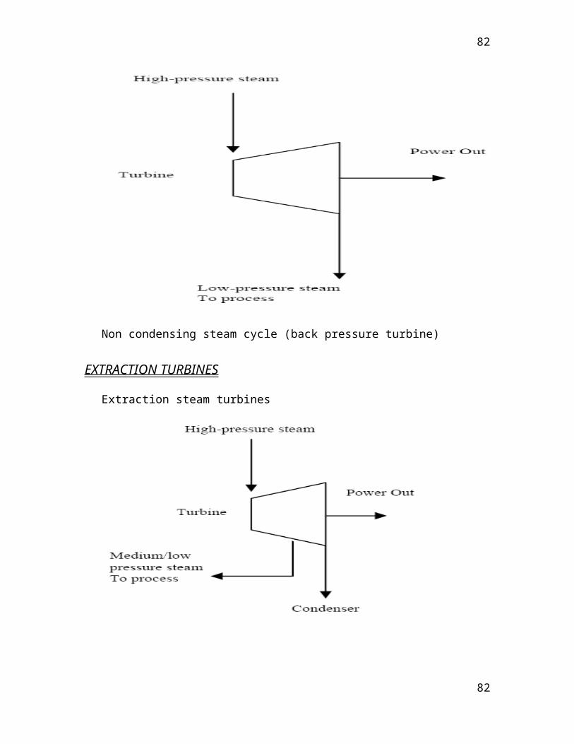
CFFP – CENTRAL FOUNDRY FORGE PLANT
(METALLURGICAL UNIT)
SMS – Steel Melting Shop
(Input Material)
Casting Group (Sand Castings)
Heavy Steel foundry
Light Steel foundry
Forging Group
Pattern making (wooden patterns) Ingot manufacturing
Moulding Recharging in furnace (1200-1300oC)
Metal heating in
furnace
Mould
Flame
Heating
Welding at
Forging press – 75000Ton Heavy duty
(90000Ton with intensifiers)
82
82

joints
Weld
strength
tests (UT,
X- ray)
Gating System Heat Treatment in furnace 1000oC
Pouring Basin – Sprue-Gate-Risers Job cooling using water air mixture spray
for attaining hardness.
Core making (Cavity in mould) Technical Audit
(QC Check)Core Baking
Molten metal pouring
Sand casting(output) Complete forged job
Machining Shop
Rough Machining
PRODUCTS
1. Castings
HP casing.
IP casing.
ESV &CV casings.
IV & CV casings
Industrial use turbine casings.
Runner’s castings.
Steel grade: Plain carbon, Alloy, Creep resistance & Stainless steel.
2. Forgings
HP rotor
IP rotor
Turbine & Generator rotors for industrial use
83
83

Rotor for gas turbine
Exciter shaft
ENGINEERING CAPABILITIES
BHEL carries out life extension programs on steam turbines of various ratings, which
forewarn the impending failure and help in reducing costly plant breakdowns by
recommending replacement and up gradation of defective components.
Over the past two decades, BHEL has gained a vast experience in design, manufacture,
erection and commissioning of various capacities of Turbine Generator sets ranging from
100 MW to 500 MW.
Many specific features to suit the customer requirements, layout & operation are taken
care of. To name a few:
Stress Evaluator, hand Barring Gear and Automatic Turbine Run-up System for 210 MW
Russian Turbine.
Base load/cycle /Two-shift operations
Throttle /Nozzle governing
Constant/Sliding pressure operation
BHEL Haridwar has a strong engineering base with qualified and experienced engineers
supported by technicians, spanning the functions of proposal, performance and product
84
84

engineering, project management, field engineering, research and development,
computerization etc.
RENOVATION & MODERNISATION (R&M)
Depending on the actual operating conditions, material properties of the components
degrade as function of service life due to one or more time dependent material damage
mechanisms such as creep, fatigue, corrosion, erosion, wear embattlement etc.
Life extension programme (LEP) is a special package comprising systems and
methodologies, which evaluates the residual life of components through sophisticated
NDT, FEM stress analysis and metallurgical technique.
Many improvements in material and design of critical components with state-of-art
design is a part of the life extension process. Thus the performance, availability and
efficiency of the plant may be improved by R&M Programs.
MICROSTRUCTURE EXAMINATION OF ROTOR
Technology / Collaborations
The technological base of BHEL in the area of Steam turbines and Turbo Generators has
been created by acquiring technological information from the collaborators. Initially
BHEL had collaboration with M/s LMW USSR for 100 and 210 MW sets. In 1976,
BHEL entered into technical collaboration agreement with M/s Siemens-KWU, Germany
85
85
to acquire the know-how and know-why for turbine generator sets upto 1000 MW. This
collaboration still continues. This helps BHEL to keep pace with the worldwide
technological progress and offer state of the art equipment to its customer. Under this
collaboration agreement, BHEL has established strong design, manufacturing and
servicing base for unit upto 500 MW ratings.
MANUFACTURING DIVISIONS
Heavy Electricals Plant, Piplani, Bhopal
Electricals Machines Repair Plant (EMRP), Mumbai
Transformer Plant P.O. BHEL, Jhansi.
Bharat Heavy Electricals Limited :
– Heavy Electricals Equipment Plant,
– Central Foundary Forge Plant., Ranipur, Hardwar
Heavy Equipment Repair Plant, Varanasi.
Insulator Plant, Jagdishpur, Distt. Sultanpur.
Heavy Power Equipment Plant, Ramachandra Puram, Hyderabad
High Pressure Boiler Plant & Seamless Steel Tube Plant, Tiruchirappalli.
Boiler Auxiliaries Plant, Indira Gandhi Industrial Complex, Ranipet.
86
86

Industrial Valves Plant, Goindwal.
Electronics Division :
– Electronics Systems Division.
– Amorphous Silicon Solar Cell Plant (ASSCP).
– Electroporcelains Division.
– Industrial Systems Group.
BANGALORE.
Component Fabrication Plant, Rudrapur.
Piping Centre, Chennai.
Regional Operations Division, New Delhi
87
87
CASE STUDY
OF FIXTURE
88
88

BRAIN STORMING FOR THE
PROBLEMS
1. PROBLEM OF DRILLING OIL JACKING HOLES IN FRONT, LP AND IP BEARINGS.
2. HALF BORE ERROR IN ALL THE BEARINGS.
3. TO MAKE SPECIAL BUSH FOR O.S.B.T PUMP.
4. PROBLEM OF MAKING RADIUS R4 IN DRG.2-112-23-05002.
5. WRONG MARKING OF THERMOCOUPLE HOLES IN THE HP BEARING
6. COLOUR CHECK OF TOURUS PIECE WITH CYLNDRICAL SUPPORT
7. PROBLEM OF SETTING THEANGLE PLATE AT RIGHT ANGLE ON THE MACHINE
89
89

8. SAND BLASTING OF OIL DUCTS
9. URGENT REQUIREMENT OF BEARINGS
10.OVALITY IN THJE LINER
HOW TO DISCOVER PROBLEMS
WHAT ARE PROBLEMS
Problems of Maintenance Problems of Improvement
HOW TO DISCOVER PROBLEMS
Problem awareness
Important points in discovering problems
Effective approaches to problems
Define problem in solvable form
90
90

IMPORTANT POINTS
IN DISCOVERING PROBLEMS
DISCOVERING PROBLEMS THROUGH OCDSM, 4M, MURI, MUDA AND 5WIH
DISCOVERING PROBLEMS THROUGH COMPARISONS
DISCOVERING PROBLEMS THROUGH CONTROL LIMITS
DISCOVERING PROBLEMS THROUGH MID AND LONG TERM OBJECTIVE
‘DISCOVERING PROBLEMS BY SIMPLIFYING AND STREAMLINING WORK
91
91

ATTRIBUTES OF A GOOD PROBLEM SOLVER
AN EXPERT AT DISCOVERING PROBLEMS
SOMEONE WHO KNOWS THE SYSTEM
SOMEONE VERSED IN QC METHOD
SOMEONE WHO LEARNS FROM FACTS
SOMEONE WITH UNDAUNTED ENTHUSIASM
A PERSON OF CHARACTER
92
92

SOMEONE WITH STRONG TECHNICAL SKILLS
SOMEONE GOOD AT LISTENING AND TALKING
A CONSCIENTIOUS PERSON
PROBLEM CAN BE CLASSIFIED IN MANY WAYS AND THE CLASSIFICATION IS ACCORDING THE
DEGREE OF OBSERVATION OF THE CAUSES AND COUNTERMEASURES NEEDED
A: Problem really worth solving
B: Problem requiring a high level of tech.
C: Simple Problem
D: Problem requiring care
Type “ A “ are the problem which are WORTH SOLVING and cannot be solved without using QC tools, This also improves problem solving capabilities
E.g.
-Reduction in no. of easy lines
93
93
-Reduction in time to service a customer
“TYPE “B “Require high level of tech. in problem solving capabilities.
E.g.
-“Sales have dropped because a competitor has opened a new store nearly”-The output is low, because the line is not fed by acceptable parts all the time”
Type “C “have simple causes and action needed to solve them are also obvious.
E.g.
-Since the temp. is not controlled at the moment, let us install thermometer and adjust thermometer based on reading
Type “D“problems are those where necessary action is known, but the causes are not so clear.Appearence of the causes of a problem would mean acting against phenomenon for not eliminating the root causes.
E.g.
-A company faced with a large no of defective electronic parts may add on aging process to its production line in order to bring defective to light but there can be more problems. There for prevention of recurrence not assessed.
94
94

ALWAYS REMEMBER FUNDAMENTAL
RULES OF PROBLEM SOLVING
Adoption of these rules brings lot of saving and cultural change.
GOLDEN RULE OF 3 R’s
Make a “RULE “ i.e what you want to achieve.
“ ROUTE “ your objective to achieve targets
Define “RULE “ i.e. for each person involved in enroot.
To achieve above we must remember principle of 3A’s for defining a problem Observe Actual Problem Observe actual problem place
95
95

Observe actual Situation
ALWAYS REMEMBER RULE’S OF FIVE W’s & ONE H
WHAT WHEN WHERE WHY WHO HOW
WHAT IS A SYSTEMATIC PROBLEM SOLVING?
Step by step systematic approach provides a sense of discipline in problem solving this helps in working towards prevention rather than a curve. In other words systematic problem solving helps in shifting from free fighting to lasting QUALITY IMPROVEMENTS
PDCA CYCLE
All systematic problem solving in quality improvement process follows from basic demming cycle which is commonly known as PDCA CYCLE
PLAN
First make the objective, problem area or improve opportunity clear and set up the mean to achieve the same.
DO
Put the plan into practice.
96
96

CHECK
Observe the results to see if the desired objective is achieved.
ACT
If there is progress standardize the plan otherwise review the plan
97
97
PDCA CYCLE
98
P (plan)
D (do)C (check)
A (act)
98

SUBJECT OF THE CASE
STUDY
DRILLING OF DIA 5MM HOLES AT DOUBLE ANGLE OF
11 AND 3O DEGREE IN LP, IP, AND FRONT BEARINGS.
99
99

PRESENT SITUATION
ON THE MACHINE WHILE DRILLING DIA 5MM HOLES OF
JACKING LINES BEARING WAS HANGED BY CRANE FOR
SETTING THE BEARING ON MACHINE BY PUTTING SUITABLE
PACKINGS UNDER THE BEARING AND ANGLE OF 11 DEGREE
WAS MAINTAINED WITH THE HEPL OF BEVEL PROTECTOR AND
30 DEGREE ANGLE WAS GIVEN BY TILTING THE MACHINE
TABLE AND THE JOB WAS SET ON THE MACHINE.
100
100

OBJECTIVES
QUALITY IMPROVEMENTS
PRODUCTIVITY IMPROVEMENT
REDUCTION ON ELECTICITY COST
REDUCTION IN OVERALL COST
101
101

DATA COLLECTION AND ANALYSIS
1. SETTING TIME 60%
2. CRANE HOLD UP 10%
3. INACCURACY 20%
4. REDUCTION IN EFFICIENCY 10%
102
102

BRAIN STORMING FOR SOLUTION
1. A FIXTURE SHOULD BE MADE AT OUR OWN SHOP BY OURSELF
2. TECHNOLOGIST SHOULD BE ASKED TO PROVIDE THE FIXTURE
3. PACKING SIZE SHOULD BE CALCULATED AND PACKING OF REQUIRED SIZE SHOULD BE MADE TO PUT UNDER THE BERAING.
103
103
RECOMMENDATION
MAKE AND DESIGN A FIXTURE AT OUR OWN SHOP BY OURSELF
104
104
INTERECTION WITH OTHER
AGENCIES
1. TECHNOLOGY
2. QUALITY
3. FINANCE
105
105

IMPLEMENTATION STATUS
FIXTURE IS BEING USED IN ALL THE BEARINGS
FOR DRILLING OIL JACKING HOLES
99 BRGS. OF LP, IP, HP AND FRONT BEARINGS ARE MACHINED IN LAST YEAR.
SAVING IN TIME = 8 HOURS PER BEARING
TOTAL SAVING IN TIME = 99*8 = 792 MAN HOURS
TOTAL SAVING IN CRANE HOURS = 99
106
106

DATA AFTER IMPLEMENTATION
1. SETTING TIME 10%
2. CRANE HOLD UP 2%
3. INACCURACY 2%
4. EFFICIENCY 86%
107
107

RESULTS COMPARISION
BEFORE AFTER
DIFFERENT SIZES OF PACKINGS FIXTURE IS USED TO CLAMP WERE USED FOR THE GIVEN ANGLES THE JOB.
TO CLAMP THE JOB.
CHANCES OF LOOSENING THE NO CHANCES OF LOOSENING THE JOB. JOB.
SAFERTY DECREASED SAFETY INCREASED INCREASED TIME REDUCTION IN TIME INCREASED COST REDUCTION IN COST LESS PRODUCTIVITY PRODUCTIVITY INCREASED WAITING TIME OF CRANE HOLD UPS OF INCREASED CRANE DECREASED QUALITY IMPROVED
108
108

GAINS
INTANGIBLE
SAVING IN TIME
SAFERTY INCREASED
CUSTOMER SATISFACTION
REDUCTION IN FATIGUE
PRODUCTIVITY
TIMELY SUPPLY OF REPAIR AND OTHER BEARINGS TO
CUSTOMER
THUS THE POWER PROBLEM OF COUNTRY IMPROVED
109
109

GAINS
TANGIBLE
PRODUCTIVITY INCREASED
COST OF 1 HR. OF RUNNING THE HORI. BORING M/C= 150 rs.
SAVING IN TIME IN ONE BRGS.= 8 HOURS
SAVING IN COST OF 100 BRGS/YEAR= 150*800= 1,20,000
SALERY OF OPERATOR PER DAY= Rs. 374
MAN DAY SAVED PER YEAR= 100
SAVING IN SALERY COST PER YEAR= 100*374= Rs. 37,400
SAVING IN CRANE PER YEAR FOR 100 HRS= Rs. 15000
GRAND SAVING PER YEAR = Rs. 1,20,000+Rs. 37400+ Rs. 15000 = Rs. 1,72,400
THIS IS A RECURRING GAIN.
110
110

Case study of
Template
111
111

Problem
Job’s name casing
In this job diameter of 41mm is made at a distance of 12.4mm on taper face and distance 584.6-0.2 depends on this diameter.That’s why it is necessary that this diameter should be made correctly. It is checked by quality control department on 3D machine but it is difficult to measure by taper gauge provided by technology department and there are chances of damage of job.
112
112

New Methods
Use of bevel protector to check the degree of taper.
Use of J & F taper gauge for colour matching.
12.4mm cut is made by measuring with gear tooth vernier.
Use of a template to measure diameter 41mm at adistance of 12.4mm.
113
113

Important Suggestions
1. A template should be made.
2. Check carefully with technology gauge.
3. Check the taper with bevel protector.
4. Use the gear tooth vernier.
5. Send the problem to technology department and wait for the solution.
114
114

Solution Given
A template should be made with the help of which diameter of 41mm should be measured correctly at a distance of 12.4mm on the taper face.
115
115
Problem Solving Graph
116
116

BIBLIOGRAPHY
B.H.E.L SITES
B.H.E.L. MANUALS
DAILY DIARY
MR. S.HALDAR (Senior Manager, BHEL)
MR. MANJINDER SINGH (Training Incharge, S.B.S.C.E.T, FEROZEPUR)
117
117