bhel bhopal training report
DESCRIPTION
BHEL BHOPAL TRAINING REPORTTRANSCRIPT

PROJECT REPORT ON
HYDRO GENERATOR (H.G.E. DEPARTMENT)
BHOPAL(26th
MAY 2014 TO 12th JULY 2014)
MALAVIYA NATIONAL INSTITUTE OF TECHNOLOGY,JAIPUR(RAJASTHAN)
GUIDED BY:- SUBMITTED BY: Amit kumar verma Ashok Tetarwal (SENIOR ENGINEER,H.G.E division) (VOCATIONAL TRAINEE)
DEPARTMENT OF ELECTRICAL ENGINEERING(B.Tech,VII SEMESTER)
MNIT JAIPUR (RAJASTHAN)

CERTIFICATE
This is to certify that ASHOK TETARWAL of VII Semester, ELECTRICAL
Engineering MNIT JAIPUR(RAJ.) has duly completed his major training from
H.G.E shop (block-1) of BHEL Bhopal. He completed his training from 26th
May 2014 to 12 July 2014.
His performance has been found satisfactory during the training. I have him sincere ,hardworking and technically sound. He regularly attended industrial under my able guidance. I take this opportunity to wish them well for the future.
Project Guide:- Mr. Amit Kumar Verma Sr Engineer H.G.E (Block-1)

ACKNOWLEDGEMENT
“An engineer with theoretical knowledge is not complete engineer. Practical knowledge
is very important for an engineer to develop and apply engineering skills”. It gives me a
great pleasure to have an opportunity to acknowledge and to express gratitude to those who
were associated with my training at Bharat Heavy Electricals Limited, Bhopal.
Summer training at BHEL-Bhopal had been an invaluable and enriching experience for me.
During this training I have learnt to apply my theoretical concepts in practical field. For this I
am quite thankful to all people with whom I got opportunity to interact.
First of all, I express my sincere thanks and gratitude to BHEL HR Deptt. forgiving me
an opportunity to do my Industrial Training in this prestigious organization.
With a deep sense of gratitude, I wish to express my sincere thanks to my guide, MR.
AMIT KUMAR VERMA, Sr engineer of HYDROGENERATOR Engineering Department
for giving me the opportunity to work under him on this project. I truly appreciate and value
his esteemed guidance and encouragement from the beginning to the end of this project.
Special thanks to Mr. Vivek Goswami, Mr. Amit Bangia, Mr. Vikas Mishra, Mr. Surendra
chauhan, Mr.Op meena, Mr. Tikendra kumar and many more who guided me & my
discussion with them was truly enlightening. I would again like to express my sincere thanks
to all project guides for their constant friendly guidance during the entire stretch of this
report. Every new step I took was due to their persistent enthusiastic cooperation, generosity
and superb guidance and I acknowledge this with a deep sense of gratitude.
I would also like to thank all employees for their friendly and warm attitude, which
helped me in completing the project successfully.

ABSTRACTThe following report presents a brief overview of the Hydro Generator and its
components and sub-assemblies. Starting with the introduction of BHEL, one of the
Maha-Navratna Company of India, the various products produced by BHEL is listed
below, and then a brief description of products related to Power Generation is given.
The report then takes the topic Hydro Generator in detail. The working principle, the
Faraday’s Law, is glanced upon. Construction detail of the hydro generator is also
included in a conducive manner. Finally the report ends with brief description of
some design parameter.

PREFACE
Design and manufacturing of Hydro-generators, requires an appreciation of
multidisciplinary concept and in depth knowledge or scientific analytical tools, geared
to the solution of real life problems. No doubt every real situation is unique but a set
of theoretical tools of knowledge can help in developing the mechanism for handling
such situation.
To acquaint me with such challenging situation, I am allowed to go to BHEL,
Bhopal. The training period was of 6 weeks which was too short to find out an
efficient feasible solution to the problem of Electrical Engineering, so I have tried my
best to collect all relevant data and studied the details of generators designed and
produced at BHEL.
I whole heartedly appreciate the atmosphere provided to me by the staffs of
Electrical Engineering. The data has been collected at primary source through
discussions with officers of different sections. For this nice gesture on their part, I
shall ever remain obliged to them.
.....................................................

Bharat Heavy Electricals Limited (BHEL) is the largest engineering and
manufacturing enterprise in India in the energy-related and infrastructure sector which
includes Power, Railways, Telecom, Transmission and Distribution, Oil and Gas
sectors and many more. These sectors have been supplied with endless number of
equipment manufactured by BHEL.
BHEL was established more than 50 years ago, ushering in the indigenous Heavy
Electrical Equipment industry in India. The company has been earning profits
continuously since 1971-72 and paying dividends since 1976-77.It is one of India's
nine largest Public Sector Undertakings or PSUs, known as the “Maha-Navratnas” or
'the nine jewels'.
BHEL manufactures over 180 products under 30 major product groups and caters to
core sectors of the Indian Economy viz., Power Generation & Transmission, Industry,
Transportation, Telecommunication, Renewable Energy, etc. The wide network of
BHEL's 14 manufacturing divisions, four Power Sector regional centers, over 100
project sites, eight service centers and 18 regional offices, enables the Company to
promptly serve its customers and provide them with suitable products, systems and
services -- efficiently and at competitive prices. The high level of quality & reliability
of its products is due to the emphasis on design, engineering and manufacturing to
international standards by acquiring and adapting some of the best technologies from
leading companies in the world, together with technologies developed in its own R&D
centers.
As an engineering conglomerate, BHEL offers over a wide spectrum of products and
services for core sectors including power generation, transmission and distribution;
transportation; and oil and gas, as well as the supply of non-conventional energy
systems.
Over 65 percent of power generated in India comes from BHEL-supplied equipment.
Overall it has installed power equipment for over 90,000 MW.

BHEL Bhopal
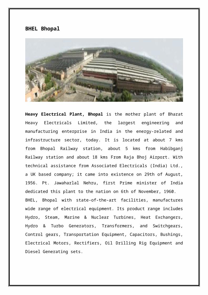
Heavy Electrical Plant, Bhopal is the mother plant of Bharat Heavy Electricals Limited, the
largest engineering and manufacturing enterprise in India in the energy-related and
infrastructure sector, today. It is located at about 7 kms from Bhopal Railway station, about 5
kms from Habibganj Railway station and about 18 kms From Raja Bhoj Airport. With
technical assistance from Associated Electricals (India) Ltd., a UK based company; it came
into existence on 29th of August, 1956. Pt. Jawaharlal Nehru, first Prime minister of India
dedicated this plant to the nation on 6th of November, 1960.
BHEL, Bhopal with state-of-the-art facilities, manufactures wide range of electrical
equipment. Its product range includes Hydro, Steam, Marine & Nuclear Turbines, Heat
Exchangers, Hydro & Turbo Generators, Transformers, and Switchgears, Control gears,
Transportation Equipment, Capacitors, Bushings, Electrical Motors, Rectifiers, Oil Drilling
Rig Equipment and Diesel Generating sets.
BHEL, Bhopal certified to ISO: 9001, ISO 14001 and OHSAS 18001, is moving towards
excellence by adopting TQM as per EFQM / CII model of Business Excellence. Heat
Exchanger Division is accredited with ASME ‘U’ Stamp. With the slogan of “ Kadam kadam
milana hai, grahak safal banana hai”, it is committed to the customers.
BHEL Bhopal has its own Laboratories for material testing and instrument calibration which
are accredited with ISO 17025 by NABL. The Hydro Laboratory, Ultra High Voltage
laboratory and Centre for Electric Transportation are the only laboratories of are used in
industries dealing in various types of chemicals. BHEL is manufacturing different types of
shell and tube type heat exchangers for industries like Refineries, Petrochemicals and
Fertilizers, etc.

BHEL Bhopal's strength is its employees. The company continuously invests in Human
Resources and pays utmost attention to their needs.

PRODUCTS MANUFACTURED AT BHEL, BHOPAL
Different types of products are manufactured here depending primarily on the
utilization of it. Some of the important mechanical products being manufactured
here are:
HYDRO TURBINES
HYDRO GENERATORS
HEAT EXCHANGERS
RUBBER EXPANSION JOINTS
FLASH TANKS
STEAM TURBINES
Power Utilization
AC Motors &Alternators
Transportation
Transportation Equipment
Power Generation
Hydro Turbines Hydro Generators Heat Exchangers Excitation Control Equipment Steam Turbines
Miscellaneous
Oil Rigs Fabrication
Power Transmission
Transformer Switchgear On-Load Tap Changer Large Current Rectifiers Control & Relay Panels
Renovation & Maintenance
Thermal Power Stations
HYDRO GENERATORIntroduction-
Generator is a device that converts mechanical energy to electrical energy. A
generator forces electric current to flow through an external circuit. The source of
mechanical energy may be a reciprocating or turbine steam engine, water falling
through a turbine or waterwheel, an internal combustion engine, a wind turbine, a
hand crank, compressed air, or any other source of mechanical energy. Generators
provide nearly all of the power for electric power grids.
According to Faraday’s law, when there is a relative motion between the conduction
and the magnetic field then an emf is induced in the conductor. The value of the
voltage generated depends on -
the number of turns in the coil
strength of the field
the speed at which the coil or magnetic field rotates
The Faraday’s law is the principle which governs the working of a Hydro
Generator.
Mechanical Construction The main part of a hydro generator are -
Stator
Rotor
Winding
Top and bottom bracket

STATOR
Stator Frame The stator frame is designed for rigidity and strength to allow it to support the
clamping forces needed to retain the stator punching in the correct core geometry. The
stator frame is of fabricated structure adequately designed to prevent distortion during
lifting, transport or any abnormal operating condition of the generator. It usually split
into a suitable no. of sections depending on transport limitation. The frame is provided
with feet to rest on the sole plates which are grouted into the concrete foundation with
the help of foundation bolts.
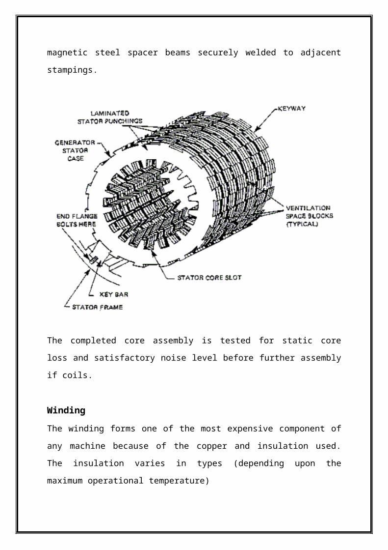
Stator core The stator core consist of laminated segment al varnished punchings made from low
loss magnetic sheet clamped between steel end plates and radial fingers securely
welded to the end plates. The clamping pressure is applied and maintained by studs
passing along the back of the core and fitted with the nuts at each end. To allow free
circulation of air for cooling purposes, ventilation ducts are provided at intervals along
the length of the stator core, these are formed by non-magnetic steel spacer beams
securely welded to adjacent stampings.

The completed core assembly is tested for static core loss and satisfactory noise level
before further assembly if coils.
Winding
The winding forms one of the most expensive component of any machine because of
the copper and insulation used. The insulation varies in types (depending upon the
maximum operational temperature)
The stator winding is of double layer type employing either a single turn bar or a multi
turn diamond pulled coil. The winding connections may be if lap or wave wound
which is chosen according to the best possible design arrangement. Each coil (or bar)
is made from a no. of strands of glass braided or lapped copper of rectangular cross
section to minimize eddy current losses.

Winding Insulation
Stator winding employs thermosetting type “Resiflex” insulation system suitable for
operation up to Class F temperatures (maximum hot spot temperature 155°C). Resin
rich epoxy bonded glass backed by mica paper is used as slot insulation and a fully
cured but flexible synthetic resin bonded glass and melinex backed mica flake tape is
used as end winding insulation. The slot portion is consolidated and cured under
pressure and temperature to ensure complete elimination of voids.
The coils/ bars are checked for dimensional accuracy to ensure correct assembly of
winding in stator core. Comprehensive testing of individual coils/bar is a part of
quality control programme.

ROTOR
Rotor Shaft and thrust block The shaft is forged from high quality medium carbon steel and is accurately machined
to gauge. The shaft has smooth bored holes through its centre for inspection purposes.
It may also be used for passing connecting tubes in Kaplan turbine or for admitting air
in Francis turbine.
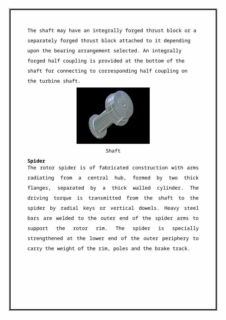
The shaft may have an integrally forged thrust block or a separately forged thrust
block attached to it depending upon the bearing arrangement selected. An integrally
forged half coupling is provided at the bottom of the shaft for connecting to
corresponding half coupling on the turbine shaft.
Shaft
Spider The rotor spider is of fabricated construction with arms radiating from a central hub,
formed by two thick flanges, separated by a thick walled cylinder. The driving torque
is transmitted from the shaft to the spider by radial keys or vertical dowels. Heavy
steel bars are welded to the outer end of the spider arms to support the rotor rim. The
spider is specially strengthened at the lower end of the outer periphery to carry the
weight of the rim, poles and the brake track.

Rim
The rim is built up from high tensile sheet steel lamination, having T shaped slots on
the outer periphery for locating the poles. The laminations are punched in the
segments covering two pole pitches and successive layers overlapped to give adequate
strength to the completed rim. The assembled laminations are clamped between heavy
steel end plates by a large no. of fine clearance bolts.
Rim assembly
Poles The poles are also made up from high tensile steel sheet laminations and clamped
between heavy steel end plates by a large no. of bolts. Both the punching and end
plates have one or more T- shaped or dovetails projections which would engage with
the corresponding slots in the rotor rim. Each pole is firmly secured by means of a pair
of taper key. The pole profile is circular, the radius of the profile being chosen so as to
ensure a suitable grading of the air gap.

Field winding
Windings being one of the most expensive component of the machine, special
attention is given to fabrication of it. Resiflex insulation system is used for the
insulation of winding. The field coils are square ended being fabricated from straight
length of copper strap, dovetailed and silver brazed at ends. At intervals down each
coil, the copper is increased in width to give fins for cooling purposes.
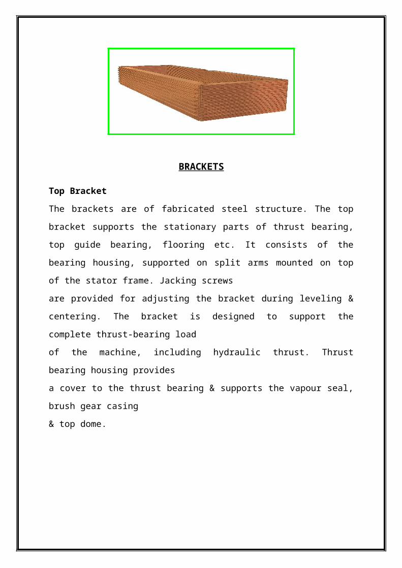
BRACKETS
Top Bracket
The brackets are of fabricated steel structure. The top bracket supports the stationary
parts of thrust bearing, top guide bearing, flooring etc. It consists of the bearing
housing, supported on split arms mounted on top of the stator frame. Jacking screws
are provided for adjusting the bracket during leveling & centering. The bracket is
designed to support the complete thrust-bearing load
of the machine, including hydraulic thrust. Thrust bearing housing provides
a cover to the thrust bearing & supports the vapour seal, brush gear casing
& top dome.
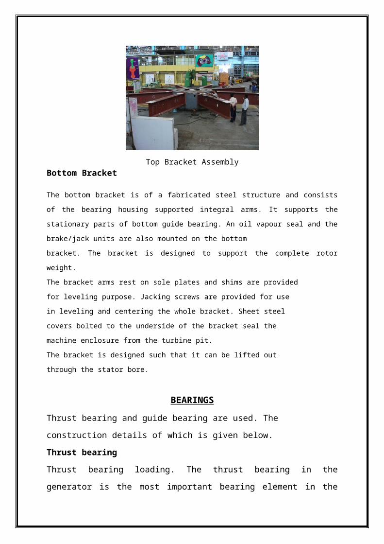
Top Bracket AssemblyBottom Bracket
The bottom bracket is of a fabricated steel structure and consists of the bearing housing supported
integral arms. It supports the stationary parts of bottom guide bearing. An oil vapour seal and the
brake/jack units are also mounted on the bottom
bracket. The bracket is designed to support the complete rotor weight.
The bracket arms rest on sole plates and shims are provided
for leveling purpose. Jacking screws are provided for use
in leveling and centering the whole bracket. Sheet steel
covers bolted to the underside of the bracket seal the
machine enclosure from the turbine pit.
The bracket is designed such that it can be lifted out
through the stator bore.
BEARINGS
Thrust bearing and guide bearing are used. The construction details of which is given
below.
Thrust bearing
Thrust bearing loading. The thrust bearing in the generator is the most important
bearing element in the generator-turbine assembly as it carries not only the weight of
the rotating generator parts, but the weight of the turbine shaft and turbine runner, in
addition to the hydraulic thrust on the runner. The allowable hydraulic thrust provided
in standard generator design is satisfactory for use with a Francis runner, but a Kaplan
runner requires provision for higher-than-normal thrust loads .
The thrust bearing is of two type
Spring supported type- the thrust pad segments are of stress relived mild steel and
are faced with a high quality white metal. Each segment rests on a number of springs
which are pre-compressed and permanently locked to a standard overall length.
Adjustable shoe type- the thrust bearing of the pivoted adjustable pad type is self-
lubricated and immersed in an oil-bath .
Guide bearing
A guide bearing is usually provided adjacent to the thrust bearing and is lubricated by
the oil in the thrust bearing pot. .The guide bearing is of pivoted pad type consisting of
a row of white metal pad arranged to be mounted on a support ring. The guide pads
have a bearing on a journal surface machined on the periphery of the thrust collar. A
pivot bar is located at the back of each guide bearing pad to rock slightly to take up a
suitable position and to facilitate the formation of oil film when running.
BEARING ARRANGEMENTS
In vertical shaft hydro generators, 4 well recognized arrangements as discussed
below are usually adopted.
Suspended Type (Top Thrust Bearing) Arrangement
In this arrangement, the thrust and one guide bearing are above the rotor and one
guide bearing below it. The thrust bearing bracket spans across the stator in this
arrangement. The thrust bearing coolers are more readily accessible. This arrangement
results in taller machines and where the stator diameter is larger, the thrust bearing
bracket becomes massive. Bearings are insulated against circulating shaft currents.
This arrangement is used for higher speed units where stator & rotor diameter are
small.

Short Coupled Type Arrangement
This is similar to suspended rotor arrgt. except that the bottom guide bearing is
omitted. It is sometimes possible to extent turbine shaft right up to the generator rotor.
This arrgt. is normally adopted for small high speed machines.
Umbrella Arrangement
In this arrangement, one guide & thrust bearing is below the rotor and there is no
guide bearing at the top of the rotor.
This type of construction is usually preferred where ever possible on account of its
simplicity and economy. It is practicable to have this arrangement for generators with
large diameter and short core length (slow speed machines). Such type rotor is more
stable while revolving than one with a small diameter and long core.
Semi Umbrella Arrangement
In this arrgt. the thrust bearing is provided below the rotor. There is one guide bearing
above & one below the rotor. The thrust bearing housing has to span smaller pit, the
dimensions of which are decided by the largest turbine component which has to be
lowered into the pit.
The arrangement is normally adopted for the machines where umbrella arrangement
cannot be adopted and suspended rotor arrangement is uneconomical.
GD 2 or Flywheel Effect
The flywheel effect (GD2) of a machine is expressed as the mass of the rotating parts
multiplied by the square of the radius of gyration. The GD2 of the generator can be
increased by adding weight in the rim of the rotor or by increasing the rotor diameter.
Increasing the GD2 increases the generator cost, size, and weight, and lowers the
efficiency. The need for above-normal GD2 should be analysed from two standpoints,
the effect on power system stability, and the effect on speed regulation of the unit.
Need for GD2
Electrical system stability considerations may in special cases require a high GD² for
speed regulation. As GD² is only one of several adjustable factors affecting system
stability, all factors in the system design should be considered in arriving at the

minimum overall cost. Sufficient GD² must be provided to prevent hunting and afford
stability in operation under sudden load changes.
Cooling
Losses in a generator appear as heat which is dissipated through radiation and
ventilation. The generator rotor is normally constructed to function as an axial flow
blower, or is equipped with fan blades, to circulate air through the windings. Small-
and moderate-size generators may be partially enclosed, and heated generator air is
discharged into the generator hall, or ducted to the outside. Larger machines are
enclosed in an air housing with air/water heat exchangers to remove heat losses.
Water-cooled heat exchangers used in a recirculated air cooling system consist of
groups of thin-walled finned tubes with appropriate water boxes, valves, and headers.
The water supply line to the air coolers should be separate from the water line to the
thrust-bearing cooler. It may prove desirable to modulate the water flow to the air
coolers to control the generator temperature, or to shut it off entirely when the unit is
being stopped. It is desirable to keep a full flow of water through the thrust bearing oil
cooler whenever the unit is turning.
APPLICATION OF HYDROGENERATOR:

HYDRO GENERATOR DESIGNING
BASIS OF DESIGN
• CUSTOMERS’ REQUIREMENT
POWER
VOLTAGE & VARIATION
FREQUENCY & VARIATION
LAYOUT, SPACE
• DATA OF PRIME MOVER
SPEED, RUNAWAY SPEED
HYDRAULIC THRUST
MASS MOMENT OF INERTIA
• LIMITATIONS
TRANSPORT
MANUFACTURING FACILITY
• SPECIAL FEATURES
LARGE WEIGHT AND SIZE HENCE SITE ASSEMBLY
LARGE STORAGE PERIOD
HEPs LOCATED IN REMOTE AREAS
SELECTION CRITERION
The customer usually draws specification of performance (consisting of
geographical conditions, hydraulic parameters, etc) based on which hydro
electric generators are designed
These cannot be transported to site in single piece and hence the machines are
based on knock down technology and are sent in the form of loose items which
are assembled at site to create a generator
The main data required by design engineer for designing a machine are kVA,
power factor, line voltage, frequency, number of phases, limits of temperature
rise of windings and core, rated speed, over speed on throwing off full load
with the governor becoming inoperative and the flywheel effect required to
ensure satisfactory speed regulation of hydraulic turbine.
Tendering Process
o BHEL basically looks for E & M packages projects.
o The various companies advertises through newspapers and internet for their
projects.
o In Delhi Corporate Office, there is Hydro Marketing Division whose function
Is to look for these advertisements and also deal with the customer throughout.
o Then these details are sent to HSS (Hydro Sales and Services) at BHEL-
Bhopal. It has two functions :-
I. To establish a link between Delhi Corporate office and HGE Deptt.
II. It also deals with customers for payment and all when project execution
takes place.
o All the companies participating in the bid are given a detailed document by
customer known as tender document which consists of customer’s demands
and specifications
o In the tendering section of HGE, a detailed study of this document is carried
out and a summary is prepared containing important points so that at the time
of discussion, all queries can be cleared with customer. This discussion is
called pre-bid meeting.
o At discussions all companies participate, queries are cleared and after this the
customer standardizes or makes changes as a standard for all companies
according to its suitability.
o Then the final report with all the technical and financial aspects included is sent
to the customer through HSS before the final date for bid.
o At bid the company which meets all the technical specifications required with
high efficiency and lowest price is chosen for the project.
o When the company gets the final offer, it executes the final designing of each
component, manufacturing, erection, assembly and commission.
Conclusionary Remark
It is said that knowing the game is one thing and playing the same is another. On the
field it is the application of the knowledge that will give fruitful result. It is on the
field that we came to know how well we can play the game. Engineering in the same
way requires the practical application of the bookish knowledge we have. The four
weeks of internship that I had at BHEL Bhopal gives me an opportunity to see things
as they happens in the engineering unlike in books where two plus two is always 4.
BIBLIOGRAPHY
http://en.wikipedia.org/wiki/Stator
http://en.wikipedia.org/wiki/Electric_generator
www.bhelbpl.co.in
BHEL Manuals
Daily Diary