summer training in bhel(www.highspeeddownload.blogspot.com)
DESCRIPTION
this is my training report for major training at bhelTRANSCRIPT
Industrial Training Report
On
Telecommunication Systems
In
Telephone Exchange
Submitted By: Your nameRoll no: -------------Electronics & Communication Engineering
Submitted To: Mr. --------- (DGM)Telecommunication Dept., BHEL, HEEP, Haridwar
BHEL, Haridwar Page 1
Dehradun Institute of Technology DehradunMakkawala,Mussoorie Road,Dehradun-248009Uttrakhand, India
Bharat Heavy Electricals LimitedHEEPRanipur, Haridwar - 249 403 Uttaranchal, India
CERTIFICATE TO WHOM IT MAY CONCERN
This is to certify that Mr. Your name student of B.Tech, Electronics and Communication Engineering, Enroll. No. -------, from Dehradun Institute of Technology, Dehradun has undergone 4 week industrial training in telecommunication systems under the guidance of Mr. ---------, Dy. GM at telecom division of Heavy Electrical Equipment Plant (HEEP), Bharat Heavy Electricals Limited (BHEL), Haridwar from June 12, 2009 to July 13, 2009. His discipline and performance during the training period was excellent. We wish him a very prosperous and bright career in future.
Mr. -------------- Mr. ---------Deputy General Manager Sr. TechnicianWEX – Telecom WEX - TelecomHEEP, BHEL, HEEP, BHEL,Haridwar - 249403 Haridwar – 249403
ACKNOWLEDGEMENTBHEL, Haridwar Page 2
First and foremost, I would like to thank my respected parents, who always encouraged me and taught me to think and workout innovatively what so ever be the field of life.
I pay my greatest regards to Mr. --------- (D.G.M. – Telecom), who provided me valuable guidance and all technical support, which was very essential for completion of the training.
I also wish to thanks Mr. --------, (Sr. Technician – Telecom) for their kind and continual support and constructive suggestions given during the course of this training. Who helped me a lot in giving minute details of Telecom Department and enlightened me with the knowledge of Exchange equipment and their working.
Last but not the least I would like to thanks my co-trainees -------- & ------------ and all the staff of HEEP (BHEL) who devoted their time for me despite their busy schedule.
_______________
Your name
BRANCH Electronics & Communication Engineering Academic Year 2010
Institute ----------------------------
ContentsBHEL, Haridwar Page 3
1. Introduction to Organisation 5 - 7
2. Introduction to Telephonic System 8
3. Telecommunication 9
4. Electronic exchanges 10 - 14
5. Telephone Lines 15
6. Connection Types 16
8. General faults Occurring in an Exchange 17 - 21
9. Special Features for users in various Exchanges 22 - 23
10. Optical Fibre System 24
11. Maintenance 25
1. INRODUCTION TO ORGANISATION
BHEL – An Overview
BHEL, Haridwar Page 4
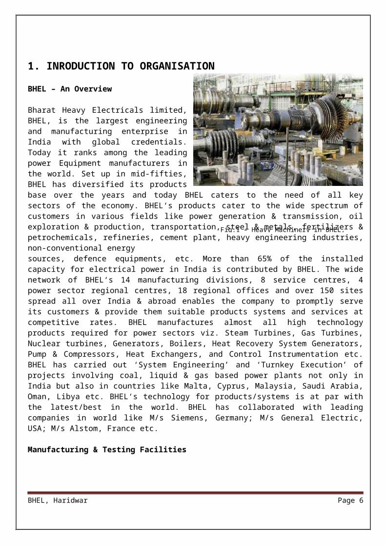
Bharat Heavy Electricals limited, BHEL, is the largest engineering and manufacturing enterprise in India with global credentials. Today it ranks among the leading power Equipment manufacturers in the world. Set up in mid-fifties, BHEL has diversified its products base over the years and today BHEL caters to the need of all key sectors of the economy. BHEL‘s products cater to the wide spectrum of customers in various fields like power generation & transmission, oil exploration & production, transportation, steel & metals, fertilizers & petrochemicals, refineries, cement plant, heavy engineering industries, non-conventional energy sources, defence equipments, etc. More than 65% of the installed capacity for electrical power in India is contributed by BHEL. The wide network of BHEL‘s 14 manufacturing divisions, 8 service centres, 4 power sector regional centres, 18 regional offices and over 150 sites spread all over India & abroad enables the company to promptly serve its customers & provide them suitable products systems and services at competitive rates. BHEL manufactures almost all high technology products required for power sectors viz. Steam Turbines, Gas Turbines, Nuclear turbines, Generators, Boilers, Heat Recovery System Generators, Pump & Compressors, Heat Exchangers, and Control Instrumentation etc. BHEL has carried out ‘System Engineering’ and ‘Turnkey Execution’ of projects involving coal, liquid & gas based power plants not only in India but also in countries like Malta, Cyprus, Malaysia, Saudi Arabia, Oman, Libya etc. BHEL‘s technology for products/systems is at par with the latest/best in the world. BHEL has collaborated with leading companies in world like M/s Siemens, Germany; M/s General Electric, USA; M/s Alstom, France etc.
Manufacturing & Testing Facilities
BHEL Haridwar plant is equipped with most modern and sophisticated machine tools, facilities and test equipment to manufacture and test turbo generators up to 1000MW rating, which includes:
New state-of-the-art total impregnation facility for impregnation wound stators of TARI/THRI type Turbo generators up to 350MW.
CNC taping machine for insulation of TG winding bars.
Most modern micalastic insulation plant for stator bars.
Over speed and vacuum balancing tunnel.
Waldrich rotor slot milling machine up to maximum barrel length of 7000mm, barrel diameter of 1400mm and rotor weight of 200 tonnes.
Koellmann rotor slot milling machine up to maximum barrel length of 7000mm, barrel diameter of 1800mm and rotor weight of 225tonnes.
Two computerised test beds to test large size Turbo generators up to 1000MW.
Wotan CNC horizontal Boring machine.
BHEL, Haridwar Page 5
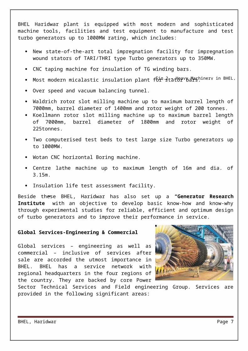
Fig.2 – Heavy Machinery in BHEL, Haridwar
Fig.1 – Heavy Machinery in BHEL, Haridwar
Centre lathe machine up to maximum length of 16m and dia. of 3.15m.
Insulation life test assessment facility.
Beside these BHEL, Haridwar has also set up a “Generator Research Institute” with an objective to develop basic know-how and know-why through experimental studies for reliable, efficient and optimum design of turbo generators and to improve their performance in service.
Global Services-Engineering & Commercial
Global services – engineering as well as commercial – inclusive of services after sale are accorded the utmost importance in BHEL. BHEL has a service network with regional headquarters in the four regions of the country. They are backed by core Power Sector Technical Services and Field engineering Group. Services are provided in the following significant areas:
Residual Life assessment (RLA) – Due to aging, material grade of sets degrade as a function of time dependent material damage mechanisms such as creep, fatigue, corrosion, erosion, wear, embrittlement etc. The residual life of components is evaluated through sophisticated NDT stress analysis & metallurgical techniques. It fare warns the impending failure and helps in reducing costly plant breakdowns by recommending replacement of defective components, retrofits etc.
Renovation & Modernisation(R&M) – As a step towards continuous effort for updating the existing designs BHEL, Haridwar offers a number of renovation and retrofit modules. Some of these are:
Rewinding of old turbo generators having bituminous stator winding of 50-235MW range, with class „F‟ insulation system.
Rewinding of old turbo generators rotors with latest Class „F‟ insulation system.
Stator water polishing unit.(Retrofit)
Control and Instrumentation for auxiliary systems for 200/210/235MW turbo generator sets.
Moisture measuring equipment.(Retrofit)
Refrigeration type gas drier.(Retrofit)
Provision of auxiliary bearing in 210MW THW type generators.(Retrofit)
Provision of top ripple springs in stator slots of THW type turbo generators.(Retrofit)
Grounding brush monitoring.(Retrofit)
Major Overhaul – BHEL undertakes periodic annual maintenance of turbo generators and also on specific customer requirement.
Spare supply – BHEL has a system of advanced planning for spares by which it is in a position to offer spares in time. Web Based – User Friendly – Catalogued spares management system is available for easy ordering by customers.
BHEL, Haridwar Page 6
Troubleshooting – Prompt door step service is provided to the customer for any problem faced in power sector viz. Turbo generator damages, malfunctioning of equipments etc.
On-line condition monitoring – for condition based maintenance of turbo generators continuous on line monitoring and diagnosis is provided.
Customer Training Programme – A comprehensive training program on the Design Features, System Philosophy, Operation & Maintenance, troubleshooting etc. of turbo generators is offered to the customer engineers and technicians to impart knowledge. Experienced faculty from concerned disciplines provide the conceptual inputs followed up by shop visits.
Quality & Reliability
Quality is prime concern for BHEL. Turbo generators manufactured by BHEL are certified ISO: 9001. The certificate is testimonial of BHEL‘s tryst with quality. It is endeavour to achieve excellence in all business processes BHEL has adopted and implemented new concepts to ensure compliance to standards/specifications at various stages of the project viz. engineering, manufacturing, testing, erection, commissioning etc.
Quality through Measurement (QTM) – provides web based management information for review, improvement and control of processes by measurement methodology. Weightage to processes and their attributes are decided on the basis of the impact of the process non – conformity based on the customer needs.
Critical to Quality (CTQ) – customer‘s special requirements are scrutinised vigorously during contact review and parameters critical to quality are identified.
Root Cause Analysis (RCA) – product and processes non – conformity data is utilised for improving products, processes and systems. BHEL, Haridwar has established a fully equipped “Central Plant Laboratory” with a large number of sophisticated testing and measuring instruments including CNC 3D Co-ordinate Measuring Machine, Non-Destructive testing facilities like X-ray, Gama-ray, Ultrasonic and Magnetic Particle Inspection. BHEL has developed vendors/sub-vendors of required quality standards through rigorous procedures for the main equipment, auxiliaries, fabrication and erection work. Today BHEL turbo generators have earned a name for high level of Reliability, Availability and Maintainability.
INTRODUCTION
BHEL, Haridwar Page 7
In past few years the field of communication has been developing with no leaps or bounds. It has become a necessity of each human being to be connected with each other. Telephone is rapidly becoming a tool to quench this thirst.
In Automatic Telephony, operators are not required to establish connections manually between the different calling and the called subscribers as are required in the case of manual telephone systems. In these system subscribers those selves establish required connections by operating the different switches placed at the central place known as the EXCHANGE from their telephones at remote place from it. The automatic telephone systems are rapidly replacing manual ones due to their outstanding merits over the latter types, some of which are enumerated below:
In Automatic Telephony higher level of secrecy is maintained due to absence of Operators who can overhear the conversation if they like in the manual telephone Systems. The working of an Automatic Telephone system does not depend for its efficiency on the personal efficiencies of the operators.
There is no possibility of the calls being missed or wrong metering being done due to faults of operators or due to phonetic errors between the subscribers and the operators.
As no operator is required, the running cost of the exchange is reduced.
TELECOMMUNICATION
BHEL, Haridwar Page 8
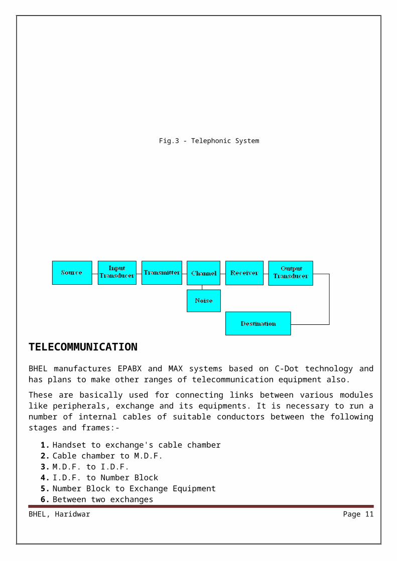
Fig.3 - Telephonic System
BHEL manufactures EPABX and MAX systems based on C-Dot technology and has plans to make other ranges of telecommunication equipment also.
These are basically used for connecting links between various modules like peripherals, exchange and its equipments. It is necessary to run a number of internal cables of suitable conductors between the following stages and frames:-
1. Handset to exchange's cable chamber2. Cable chamber to M.D.F.3. M.D.F. to I.D.F.4. I.D.F. to Number Block5. Number Block to Exchange Equipment6. Between two exchanges7. Between two cities8. Between two countries
Prior to advent of Electronic Exchanges inter-connection of various circuits are made by mechanical contacts that are operated by mechanical movements produced by the attraction of an iron armature of an electromagnet or by the operation of an electric motor. There are some disadvantages of such systems for using mechanical contacts, due to following reasons:
Contacts are subjected to wear and tear. Require adjustments time to time. Maintenance is highly precise. Prone to corrosion. etc.
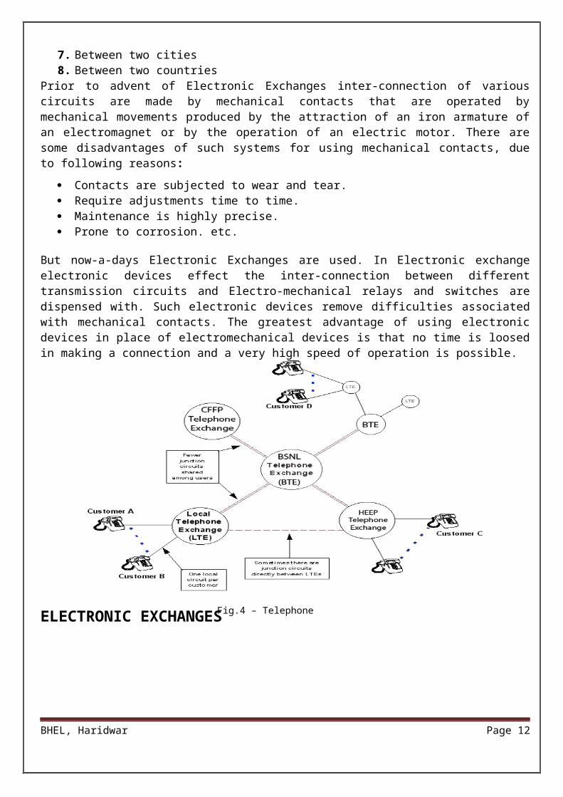
But now-a-days Electronic Exchanges are used. In Electronic exchange electronic devices effect the inter-connection between different transmission circuits and Electro-mechanical relays and switches are dispensed with. Such electronic devices remove difficulties associated with mechanical contacts. The greatest advantage of using electronic devices in place of electromechanical devices is that no time is loosed in making a connection and a very high speed of operation is possible.
ELECTRONIC EXCHANGES
BHEL, Haridwar Page 9
Fig.4 – Telephone Network, BHEL
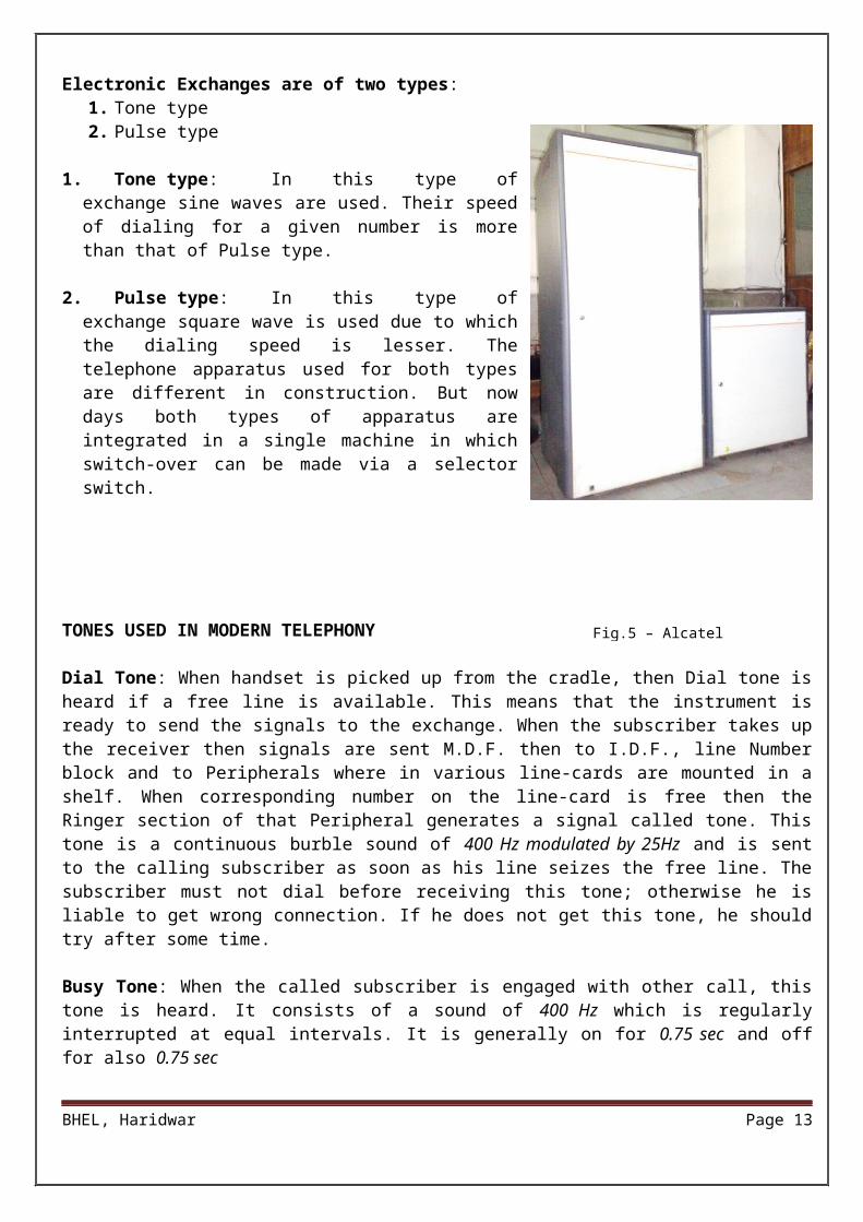
Electronic Exchanges are of two types:1. Tone type2. Pulse type
1. Tone type: In this type of exchange sine waves are used. Their speed of dialing for a given number is more than that of Pulse type.
2. Pulse type: In this type of exchange square wave is used due to which the dialing speed is lesser. The telephone apparatus used for both types are different in construction. But now days both types of apparatus are integrated in a single machine in which switch-over can be made via a selector switch.
TONES USED IN MODERN TELEPHONY
Dial Tone: When handset is picked up from the cradle, then Dial tone is heard if a free line is available. This means that the instrument is ready to send the signals to the exchange. When the subscriber takes up the receiver then signals are sent M.D.F. then to I.D.F., line Number block and to Peripherals where in various line-cards are mounted in a shelf. When corresponding number on the line-card is free then the Ringer section of that Peripheral generates a signal called tone. This tone is a continuous burble sound of 400 Hz modulated by 25Hz and is sent to the calling subscriber as soon as his line seizes the free line. The subscriber must not dial before receiving this tone; otherwise he is liable to get wrong connection. If he does not get this tone, he should try after some time.
Busy Tone: When the called subscriber is engaged with other call, this tone is heard. It consists of a sound of 400 Hz which is regularly interrupted at equal intervals. It is generally on for 0.75 sec and off for also 0.75 sec
Ringing Tone: When a number is dialed then telephone of the called subscriber starts ringing. Calling subscriber should get this information and this is indicated by sending ringing tone of interrupted 400 Hz supplies modulated by 25 Hz and its durations are generally equal to the duration of ringing current, which rings the bell. It may be 0.4 sec on, 0.2 sec off or it may be 0.75 sec on and 0.75 sec off and so on. When this ringing tone is received, the calling subscriber knows that the connection is completed and that the bell of the called subscriber is ringing.
Number Unobtainable Tone: This tone is sent when the number dialed cannot be obtained. If any subscriber dials which is not actually connected to the exchange, this indication is send. This is also a tone of 400 Hz with interruption of 200 ms at every 3 sec.
Now-a-days push button type telephone apparatus are used. This apparatus can be exploded into following sections:
1. Ringer section
BHEL, Haridwar Page 10
Fig.5 – Alcatel Exchange
2. Speech section (Transmitter and Receiver section)3. Voltage limiter section
From telephone exchange two wires or connectors run for each number, in which one is neutral and the other is main or positive. For the telephone circuit to work the necessary supply is provided by the exchange. Like other circuits telephone also operates when a circuit is established between calling and called subscriber. When one dials a number then the corresponding relays at the exchange established a circuit automatically. The telephone exchange supplies 40-60 volt DC and 110/20 Hz to operate this circuit. This is required because of voltage drop that may creep in long transmission wires. As soon as the handset is picked-up this 48-volt DC supply is available at voltage limiter section, dialing pulse generator and speech section.
In telephone dialing two types of frequencies are used which are:
High band tone (1216 Hz. to 1645 Hz.) Low band tone (701 Hz. to 936 Hz.)
Frequencies used in Telephony
The numbers from 1 to 5 falls in low band and 6 to 9, 0 falls in high band. Till the handset is on-hook, the ringing section of the apparatus is on through telephone line but on lifting the handset the ringing section becomes off, also the dialing and speech section becomes ready. On lifting the handset first the dial tone is received which is amplified by the amplifier of speech section.
When a number is pressed on the keyboard, the dialing pulses are made on and off according to the number dialed. For example if 5 is pressed then dialing pulses are made on and off 5 times. This process can be heard on the receiver. There is a gap of 1 sec. between consecutively pressed numbers.
When the handset is placed on or is lifted from the instrument a switch is operated called the hook-switch. The main function of this switch is to toggle between telephone-line and ringer, dialing & speech sections of the telephone. When the handset is on the telephone then ringer section of the telephone is on while on lifting it ringer section is disconnected and dialing section is connected.
How the telephone call is made:
Telephone call is characterized into two sections:
1. Outgoing calls: Generally a voltage of 48V-60V DC always remains on the telephone line but as the handset is picked-up the voltage limiter drops this voltage to 9-12V on hearing the dial tone it is confirmed that the apparatus is ready to work and after dialing the number a ringing pulse is send to the called party. When the calling party picks-up the handset the billing meter of the exchange becomes activated. There is a counter in the exchange, which counts the pulse and converts them into calls.
2. Incoming calls: These are just opposite of outgoing calls. In the incoming calls the telephone detects the ringing signal from the exchange and provides the ring. At the instance of ringing signal, there remains a voltage of 75-110V/20 Hz on the telephone. A high voltage (AC) is sent from the ringer section of the exchange to start the ringer circuit of the telephone. When the ringing signal is received it should be properly isolated as it may give a shock. This ringing circuit is on until the handset is not picked-up at the called party. The duration of this tone, if unattended, is 1 minute after which an engage tone is heard. After lifting the handset a circuit is established and a call is made.
BHEL, Haridwar Page 11
There are various powers providing circuits available in the exchange to run the circuitry. These are broadly categorized in two categories:
Outside the exchange Inside the exchange
Outside the Exchange:
Since the voltage supplied in Indian Subcontinent is 220-volts/50 Hz AC but for the normal working of the exchange 48(46-53) volts of DC is required.
Hence a Rectifier circuit, backed with battery array for power-failures, is used. This rectifier block not only rectifies the input supply but also works as a battery charger. It is known as Float rectifier cum charger.
Battery backup is utilized for smooth operation of the exchange during power failures. For battery back-up lead acid battery array is used in parallel to the supply from the rectifier block, so that during power failures the exchange supplies are not terminated.
Inside the Exchange:
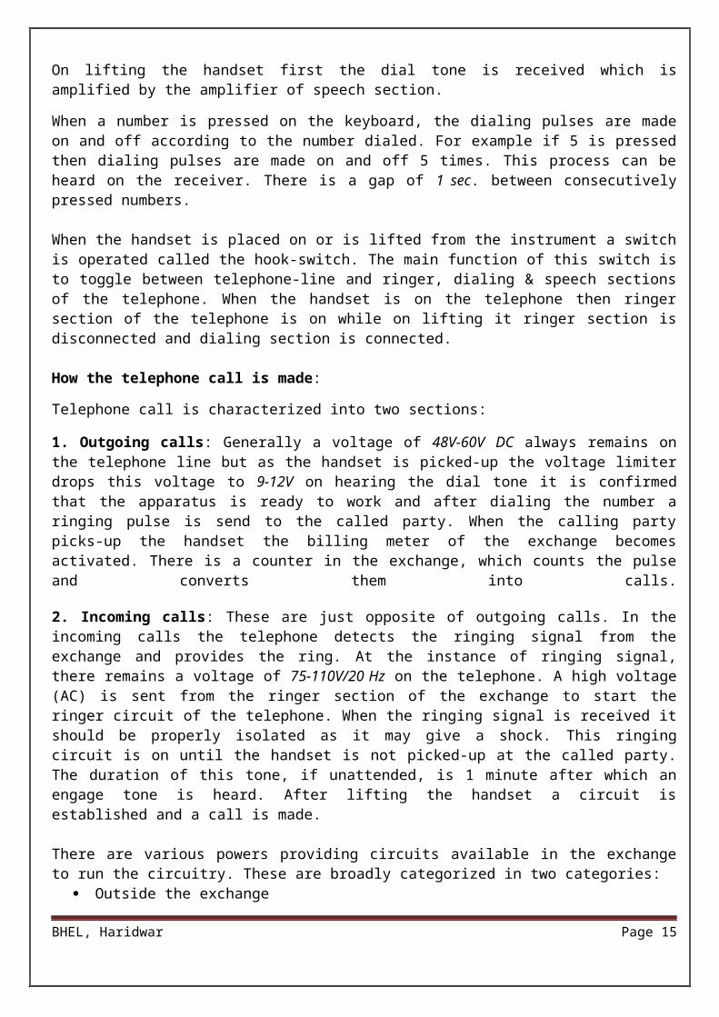
Inside the telephone exchange various types of power supplies are used for powering various modules (for example: - Line-cards, Ringer). Some of them are: -
-5 V 12 A +5 V 12 A +12 V 6A.
From M.D.F. a number of cables, based upon the requirement of a place, are connected to cabinets. On the cabinets these cables are divided into cables of 20 pairs. Now every 20 pair cable goes to the distribution box (D.B.). At the D.B. this 20 pair cable is further divided into two parts of 10 pairs each. These pairs are then connected to the subscriber ports via jumpers. The line from these ports then goes to the subscribers through single pair cables which are usually of P.V.C. type. These wires are connected to the instrument via Rosette-Box.
M.D.F
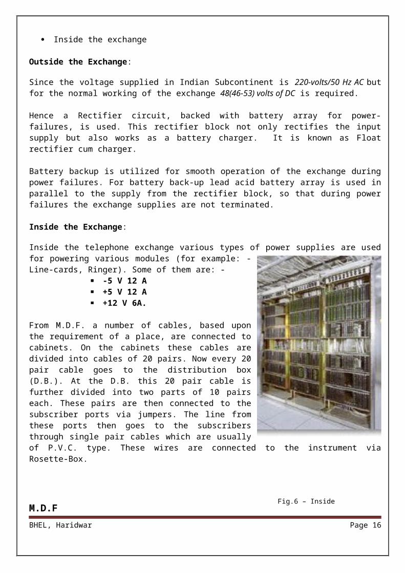
This frame serves the following purposes: -
It is place where both external and internal cables are terminated. The external individuals cable carry conductors from subscribers who are necessarily from the same locality and as such their numbers cannot be in numerical order. On the other hand, the internal cable conductors come from apparatus side in numerical order. This cross-section between the two cables is done on the M.D.F through jumper wires.
It carries all the protectors used in the exchange. The different protectors that are used are (a) Fuses, (b) Heat coils, and (c) lightning protectors.
BHEL, Haridwar Page 12
Fig.6 – Inside Exchange
This M.D.F is an ideal place for testing purpose. Both the internal and the external cables are available at this frame and, therefore, both external and internal wiring and lines can be tested for this purpose.
New MDF in Exchange
I.D.F
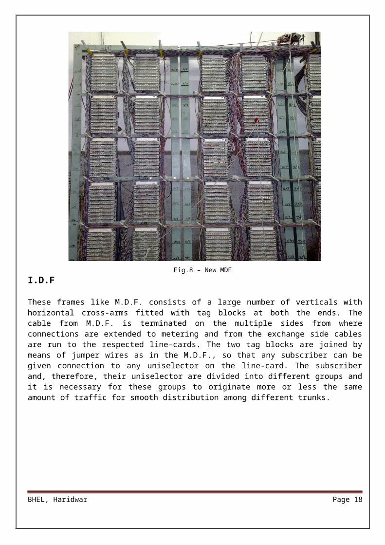
These frames like M.D.F. consists of a large number of verticals with horizontal cross-arms fitted with tag blocks at both the ends. The cable from M.D.F. is terminated on the multiple sides from where
BHEL, Haridwar Page 13
Fig.7 – Old MDF
Fig.8 – New MDF

connections are extended to metering and from the exchange side cables are run to the respected line-cards. The two tag blocks are joined by means of jumper wires as in the M.D.F., so that any subscriber can be given connection to any uniselector on the line-card. The subscriber and, therefore, their uniselector are divided into different groups and it is necessary for these groups to originate more or less the same amount of traffic for smooth distribution among different trunks.
TELEPHONE LINES
In BHEL-Hardwar three types of telephone lines are used. They are: -
BHEL, Haridwar Page 14
MAX Lines EPABX Lines C-DOT Lines MAX Lines:
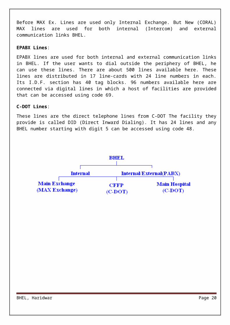
Before MAX Ex. Lines are used only Internal Exchange. But New (CORAL) MAX lines are used for both internal (Intercom) and external communication links BHEL.
EPABX Lines:
EPABX lines are used for both internal and external communication links in BHEL. If the user wants to dial outside the periphery of BHEL, he can use these lines. There are about 500 lines available here. These lines are distributed in 17 line-cards with 24 line numbers in each. Its I.D.F. section has 40 tag blocks. 96 numbers available here are connected via digital lines in which a host of facilities are provided that can be accessed using code 69. C-DOT Lines:
These lines are the direct telephone lines from C-DOT The facility they provide is called DID (Direct Inward Dialing). It has 24 lines and any BHEL number starting with digit 5 can be accessed using code 48.
CONNECTION TYPES
Types of Connections:
BHEL, Haridwar Page 15
1. With wires i.e. Cables2. Wireless Microwave Links through Satellite
Cables: Two types of Cables are used. They are:
1. Underground cables: These types of cables run under the earth and are basically used to connect the exchange to the subscriber's Distribution Box (D.B.). They are further of two types based upon their construction and the insulating material used.
a. Paper core A.T.C. (Armored Tin Cable)b. Jelly filled A.T.C. (Armored Tin Cable)
2. Overhead cables: These types of cables are used to connect the equipments inside the exchange and to connect the peripheral devices to the subscriber's Distribution Box
(DB) They are generally of P.V.C. type.
In an exchange, based upon the number of conductor pairs, following types of cables are used: Single Pair cable 2 Pairs cable 5 Pairs cable 10 Pairs cable 20 Pairs cable 50 Pairs cable 100 Pairs cable
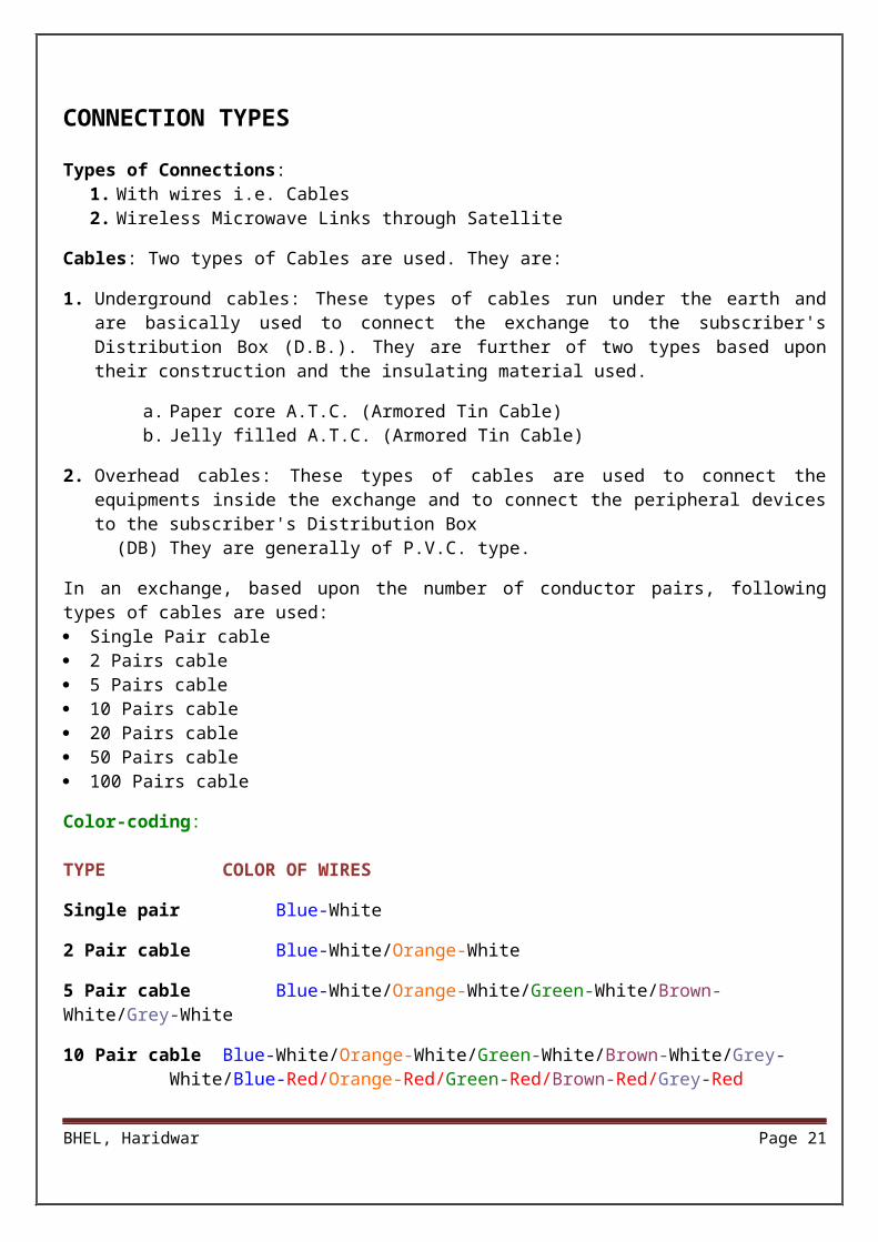
Color-coding:
TYPE COLOR OF WIRES
Single pair Blue-White
2 Pair cable Blue-White/Orange-White
5 Pair cable Blue-White/Orange-White/Green-White/Brown-White/Grey-White
10 Pair cable Blue-White/Orange-White/Green-White/Brown-White/Grey-White/Blue-Red/Orange-Red/Green-Red/Brown-Red/Grey-Red
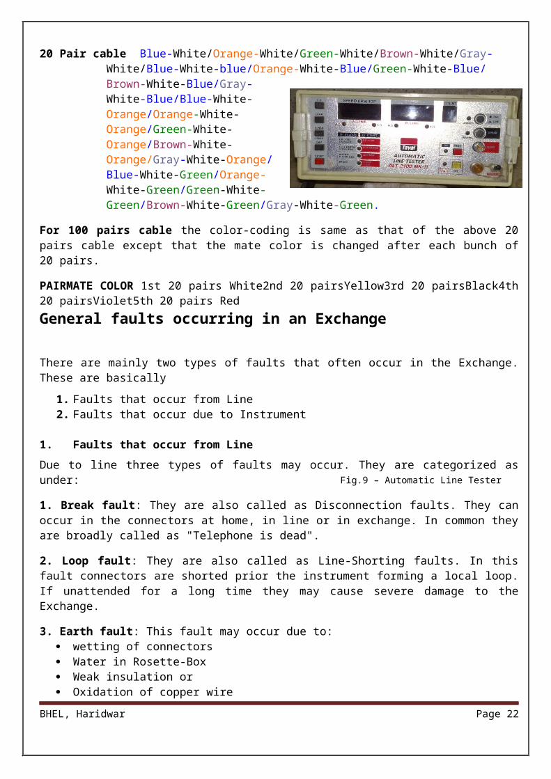
20 Pair cable Blue-White/Orange-White/Green-White/Brown-White/Gray-White/Blue-White-blue/Orange-White-Blue/Green-White-Blue/Brown-White-Blue/Gray-White-Blue/Blue-White-Orange/Orange-White-Orange/Green-White-Orange/Brown-White-Orange/Gray-White-Orange/Blue-White-Green/Orange-White-Green/Green-White-Green/Brown-White-Green/Gray-White-Green.
For 100 pairs cable the color-coding is same as that of the above 20 pairs cable except that the mate color is changed after each bunch of 20 pairs.
PAIRMATE COLOR 1st 20 pairs White2nd 20 pairsYellow3rd 20 pairsBlack4th 20 pairsViolet5th 20 pairs Red
General faults occurring in an Exchange
BHEL, Haridwar Page 16
There are mainly two types of faults that often occur in the Exchange. These are basically
1. Faults that occur from Line2. Faults that occur due to Instrument
1. Faults that occur from Line
Due to line three types of faults may occur. They are categorized as under:
1. Break fault: They are also called as Disconnection faults. They can occur in the connectors at home, in line or in exchange. In common they are broadly called as "Telephone is dead".
2. Loop fault: They are also called as Line-Shorting faults. In this fault connectors are shorted prior the instrument forming a local loop. If unattended for a long time they may cause severe damage to the Exchange.
3. Earth fault: This fault may occur due to: wetting of connectors Water in Rosette-Box Weak insulation or Oxidation of copper wire
Connectors can either touch from earth, with other connector or with any conductor (such as metallic table, frame etc.)
Problems that can occur due to line faults:1. Subscriber cannot dial a number.2. Ring Trip i.e. connection from the exchange breaks after one ring.3. False Ring 4. Low speech5. One sided speech
Faults that occur due to instrument:These may be: The number is not being dialed One way speechReceiver coil is faulty
2. Faults that occur due to instrument
Plunger or Push switch faulty. Dial tone breaks after two or three rings. From second subscriber bell is heard to be going but at first subscriber only dial tone is heard. Instrument circuitry faulty. When loop or earth fault is received than exchange can be affected so it is wedged as soon as possible
because if not wedge for longer it can damage line-card too.To sense these faults first line-side is checked and then exchange side is checked at exchange. If however exchange side is correct then line faults after detection are handed over to the concerned lineman for further checking.
BHEL, Haridwar Page 17
Fig.9 – Automatic Line Tester
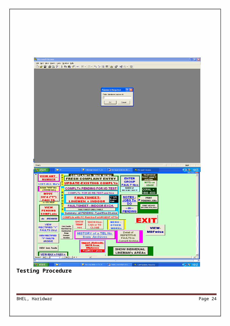
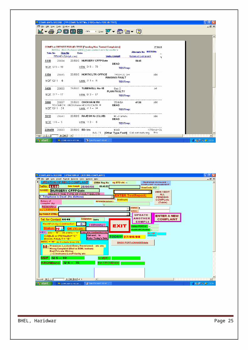
Testing Procedure
Testing Procedure
BHEL, Haridwar Page 18
Testing Procedure
BHEL, Haridwar Page 19
Testing Procedure
BHEL, Haridwar Page 20
LIST OF SPECIAL USER FEATURES ON VARIOUS EXCHANGES
BHEL, Haridwar Page 21
1. MAX (Coral India Pvt. LTD, NOIDA)
Manufacturer: Jeumont Schinedier, France Capacity: 2700 lines
Call Pick Up: 89-xxxx to pick up a call ringing at another location xxxx.
Call Transfer: 2 Parties conversing, any party can dial 3rd party, then Conversation among them Hang-up. The party on line now talks to 3rd party.
Party Conference: While speaking with a party:(From Pulse Instrument: -- If CALLER requires dialing 3rd party during conversation and maintaining talks, then dial 4.)(From Tone Instrument: -- If CALLER requires dialing 3rd party during conversation and maintaining talks, then flash, and dial 4.)
Malicious Call Trace: Dial 29 during conversation, to trace a malicious call From a MAX Extension. Then enquire from 4999 or 4424.
Appointment Reminder: Dial 80-xx-yy {xx=hrs, yy=min}. To Cancel: Dial 27.
2. EPABX = ALCATEL 4400
Manufacturer: ALCATEL, FRANCE Capacity: 500 lines (96 DIGITAL, 404 ANALOG) Technology used: PCM - TDM
Tone Mode Dial: Dial # before no. {If instrument is not tone enabled)
Call Transfer: Hook FLASH: Do Hook Flash - On hearing prompt "Please dial." Dial the no., wait for party to respond, and then disconnect.
Enquiry Call: FLASH (from Tone mode instrument.) or 2 (from Pulse mode) During converse put the 1st party on HOLD. Then, dial a 3rd party and speak.
Broker Call: (After ENQUIRY CALL): Dial 1To go BACK & FORTH, between two parties (one party in conversation & other On HOLD)
Conference-3 Party: While talking to 1st party, first make ENQUIRY CALL (Put on hold){FLASH from Tone; or 2 from Pulse}.Then - Dial 3rd party - Flash-- Dial 3.
Auto Callback: Dial 5 to book auto-callback when a busy PABX hangs up.(To cancel auto-callback request: Dial 67 or/and 848)
BHEL, Haridwar Page 22
Password Modification: 847-0000-xxxx (0000=old password; xxxx = new Password). This facility is available on STD enabled extensions only.
Last caller callback: 851 {to ring the last unattended PABX Caller}
Appointment Reminder: 852 then dial the time as {xx (hr) xx (min)} To cancel: 853
Last no. Redial: 854 User can use this if instrument doesn’t have a Redial Button.
Call Pickup: 72 - XXXX to pick up a call ringing at another extension.
Call-Park / Retrieve: It is used during an incoming or outgoing call, to speak from a different set. (To park from own (speaking) set: FLASH-855- dial own extension number. Then “Hang-up". The call is now parked, and the other party is kept on hold.(To pick up from a different set: 855- dial own extension number)(To pick up from own set (later, if not taken elsewhere) 855)
BHEL, Haridwar Page 23
OPTICAL FIBER SYSTEM
Fiber optical transmission medium is fast emerging as an alternative and strong competitor to coaxial cables in telecommunication networks.
Long distance data transmission in electrical cables suffers from ground loop problems. The merits of the optical fiber stem from the fact that the basic material used in their construction is nonmetallic and electrically nonconductive.
In contrast, the nonmetallic and totally dielectric fiber optical cable are immune to radio frequency another electromagnetic interferences. Ground loop and common mode voltage problem do not exist and data can be transmitted between points of vastly different potential. In optical cables the information is transmitted by packets of photons which have no charge. There is no possibility of sparks or short circuit when a fiber is cut. The bandwidth high compared to that of the electrical cables. The standard RG-58 coaxial cable has bandwidth distance product of a typical optical fiber is about 100 MHz-Km.
Fiber cables are about the thickness of a human hair any dirt obstructing the optical port causes poor transmission. The thin dimension results in a low weight for given length when compared to electrical cables. However, being thin and somewhat brittle in nature, fiber tend to break easily if bent beyond a certain limit a direct viewing into the optical point can be harmful to the eyes.
BHEL, Haridwar Page 24
Fig.10 – Broadband Optical Fiber System
MAINTENANCE
The subject of maintenance of Automatic Telephone Exchange can be broadly divided under two categories: -
1. Prevention of Service Failures.2. Location of Faults and their removal.
Prevention of Service Failures can be done in following ways: -
1. Suitable design and adoption of suitable adjustment standards of the equipment parts of the exchange can minimize failures in service.
2. Some preventive measures may also reduce service failures viz. keeping the rooms dust free, maintaining temperature and humidity under tolerable limits using air-conditioners.
3. Routine inspection, routine tests and routine adjustments also help in preventing service failures. When faults occur in some parts of the exchange, they should be detected and removed as quickly as possible.
Various tools are also used to check the faults in the telephone lines and for checking fault inside the exchange.
BHEL, Haridwar Page 25