bathroom installation instructions - utopia group fitting... · bathroom installation instructions....
TRANSCRIPT
Bathroom installation instructions

INSTALLATION INSTRUCTIONS
WWW.UTOPIAGROUP.COMpage 2
Contents
Base UnitsFitting Base Units 3Base Units and Drawer Packs 3Fitting Wall Hung Base and Wall Units 4Adjusting a Soft Close Drawer Box 5Fitting a Plinth 5WC Fascia Cut Outs 6Utopia Push Button Concealed Cisterns 6Dual Flush Push Button Cistern Features 6WC Panels 6 Cut-Out Semi Recessed Washbasin Units 7
Wall UnitsFitting Wall Cabinets 8Fitting the Lighting Unit 8Access and Removal of Transformers and Front Fascia 8Mirror Cabinet Handle Fitting 9Door Adjustment 9Fitting a Mirror Door onto a Unit 9Soft Close Hinge Mechanism, Removal and Re-Fitting 9
MirrorsFitting a Mirror 10Fitting Designer Illuminated, Curved and Modular Offset Mirrors 11
Lighting, Flyover Shelves and CorniceFitting Flyover Shelves 12Fitting LED Downlighters 12Fitting Chrome Bow Lights 12Fitting Wall Mounted Mirror Lights 12
Tall UnitsFitting a Tall Glass Shelf Display Unit and All Other Tall Units 13
Modular UnitsFitting Wall Hung Base and Wall Units 14Modular Mirror Fitting 15Modular & Timber Sliding Mirror 15Mirror Cabinet Handle Fitting 16Door Adjustment 16Fitting a Mirror Door on to a Unit 16Soft Close Hinge Mechanism, Removal and Re-fitting 16Fitting a Square Profile Laminate Worktop 17Basin Waste Recommendation 17Adjusting a Soft Close Drawer Box 17
Encurva Modular FurnitureFitting Encurva Basin 18Fitting Wall Hanging Brackets 18
Halo and Qube FurnitureFitting Hinged Door Mirror Unit 19Fitting Mirror Drawer Unit 19Fitting Qube Unit 20Fitting Halo Twin Base Unit 20Fitting Side Cabinet 21Fitting Cloakroom Cabinet 21
i-Line FurnitureFitting i-Line 50mm Side Panels 22Fitting i-Line wall and Mirror Units 23
Symmetry FurnitureFitting Symmetry Modular Base Units and Fitted/Freestanding Base Units 24Fitting Symmetry Worktops / Solid Surface 24Decorative End Panels 25Fitting Side Panels with an External Filler Panel 25Fitting Symmetry Plinths 25Plinth Lighting 25
Timber UnitsFitting Timber Modular and Floor Standing Units 26Decorative End Panels 26Plinth Installation 26Fitting a Timber Accessory Shelf 26
DowntonFitting Traditional Base Unit 27Downton 28
Bath PanelsBath Panel Component Identification 29Bath Panel Installation 29Definity Fitted Bath 30Definity Freestanding Bath 31Fitting Symmetry baths 32Fitting Symmetry bath side panels 32Fitting Symmetry bath side and end panels with an end storage unit 32-34
Granite/Marble WorktopsGranite Worktops 35
GeoGeo Draw Unit 36Geo Integra Solid Surface and Freeflow Basin 36
Tap HolesDrilling For Taps In the Worktop 37Drilling a Tap Hole In a Gelcast Cloakroom Washbasin 3750mm Laminate Worktops 37
Solid Surface and Laminate Worktops Installation of Laminate and Solid Surface Worktops 38Fitting a Worktop 39Installing a Washbasin into a Worktop 40Washbasin Fascia & Worktop Cut Outs 40Washbasin Waste Recommendation 40Fitting a Solid Surface Apron Standard and Short Projection 41Solid Surface Shelves and Shelf Supports 41
50mm Decorative Floating ShelvesFitting a 50mm shelf with an adjustable support 42
Painted ProductsFitting instructions 43Care and Maintenance Instructions 54
Important NoteThese fitting instructions refer to fitting Utopia Furniture to a solid wall. If your bathroom has
studded walls, please use appropriate plasterboard fixings such as the ones illustrated here, available
from DIY stores throughout the UK.
PLEASE READ THESE INSTRUCTIONS CAREFULLY BEFORE COMMENCING WORKAll units are packed together with a relevant fitting pack and are identified by a label which appears on the front of the box and the rear of the unit.
It is advised that fitting commences from a corner wherever possible, ensuring correct spacing should a corner filler be used. It is also advised that all doors and fascias are removed prior to fitting to avoid unnecessary damage occurring.
Please note that some of Utopia’s units, sanitaryware and worktops are heavy. Always take care when lifting, and follow health and safety guidelines.

WWW.UTOPIAGROUP.COMpage 3
Base Units
FITTING BASE UNITS AND TALL BASE UNITS
NOTE: SHOULD THE FLOOR BE UNLEVEL AND YOU WISH TO LOWER THE PLINTH HEIGHT FROM 175mm YOU WILL NEED TO CUT THE LEGS TO THE REQUIRED HEIGHT (REMOVING UNWANTED MATERIAL FROM THE TOP) BEFORE FITTING THEM TO THE BASE OF THE UNIT
Attach the plastic legs by pushing them into the sockets on the underside of the unit. It is advised to give the base of the leg a slight tap with a hammer to ensure a good connection in the socket (see fig 1).
Adjust the leg to approximately the correct height of 175mm (see fig 2). Having ensured all relevant pipework is completed, position the unit on its legs against the wall. Adjust the legs if necessary to ensure the unit sits level in both directions by using a spirit level on all sides (see fig 3).
Maintain the plinth height of 175mm as near to the optimum as possible.
Once the unit has been positioned level, remove the back (if applicable) and fix the unit to the wall via the back rail or stretcher plates (see fig 4). If you are attaching this unit to a plasterboard wall please ensure that you use the correct fixings.
Once all units are in place they can be joined together by means of drilling and screwing through adjacent side panels. We suggest making fixing less obvious by drilling behind hinges or loose shelves (see fig 5). Once all the units are securely fixed, ensure that all the back panels that were removed earlier are slid back into position before proceeding further.
Please note that many back panels are double-sided and have a different finish on either side. Always check that you slide the panel in with the correct finish facing forwards before the worktops are fitted (see fig 5).
Please Note
When fitting a base unit for a Short Projection Solid Surface basin, the back rail has a gap to allow the inset basin to fit nearer the wall. Fix this unit to the wall through the side cheeks of the back rail, A & B. This will also assist in supporting the worktop (see fig 6).
BASE UNITS AND DRAWER PACKS
This unit should be fitted the same way as a normal base unit. Please note drawer packs do not have 8mm slide-in backs, this allows easy access to the top rail for fitting purposes.
If your unit is to be wall hung, please refer to the section ‘fitting a wall hung base unit’ on page 4.
Important
Check all products before fitting.
Do not fit any defective products, contact your supplier immediately.
Utopia Bathroom Group assumes that this/these product/s will be fitted by an experienced and competent installer. Failure to do so will result in the invalidation of Utopia’s guarantee.
Under our policy of improvement we reserve the right to alter materials or specification in line with our continuing programme of product and service development.
fig 4
fig 3
fig 2fig 1
fig 5
A
Bfig 6

INSTALLATION INSTRUCTIONS
WWW.UTOPIAGROUP.COMpage 4
Base Units
fig 1
FITTING WALL HUNG BASE UNITS AND WALL UNITS
All base units whether with legs or wall hung come complete with leg sockets fitted for transit purposes. If the units are to be installed wall hung, please remove these sockets prior to fixing. To do this, insert a small flat-headed screwdriver into the centre section and carefully lever out the centre pin. The bracket can now be easily removed (see fig 1).
It is advised that a line is now drawn along the length of the wall, level with where the units are to be fitted at the desired height above floor level. If the space between the floor and the unit is to be 175mm then the line shown as x (see fig 2) should be drawn to suit the unit being fitted.
Wall hanging brackets need to be fixed to the carcass when they are sold separately. The brackets should be fixed the correct way up by knocking four prongs into the holes at the rear of the carcass. Ensure that the securing pin is knocked into place, (see fig 3).
Fix the brackets to the wall with appropriate plugs and screws for your wall type (not supplied).
The units then simply hook onto the wall fixed brackets. Adjustment to gain a level surface is as follows,
A - Adjust this to pull the cabinet into the wall
B - Adjust this to move the cabinets up or down (see fig 3);
Pull the cabinets tightly in against the wall using the adjustment screws on brackets. It is important to ensure you have sufficient support for the weight of pottery and unit plus contents when fitting wall hung units.
Once all units are in place they can be joined together by means of drilling and screwing through adjacent side panels. We suggest making fixing less obvious by drilling behind hinges and/or loose shelves, (see fig 4).
A securing screw should then be fitted through the back of the unit, through the fixed back rail of the cabinet and into the wall on a base unit, this will help to stabilise the unit (see fig 5 point 4).Now that all the units are securely fixed, ensure that all the back panels that were removed earlier are slid back into position before proceeding further. Please note that many back panels are double-sided and therefore have a different finish on either side. Always check that you slide the panel in with the correct finish facing forwards, (see fig 4).
For all units with a fixed back panel we advise that you drill a 10mm hole through the back panel and then fit a stabilising screw though the back rail of the cabinet into the wall. The 10mm hole can be covered with one of the caps supplied or if positioned appropriately, by the loose shelf of the unit, when applicable (see fig 6).Units should be fitted by professional installers.
fig 4
fig 3
TOP OF UNIT
Back PanelBack Rail
10mm drill
Wall
6 in/out
4
fig 5
fig 6
level line
securing pin
Ain +out
up +down B
fig 2

WWW.UTOPIAGROUP.COMpage 5
Base Units
ADJUSTING A SOFT CLOSE DRAWER BOXDrawer boxes are factory installed and should not need to be adjusted. However, if adjustment is required, pull the drawer box out and remove the Utopia branded plastic cap. This will reveal the two adjustment screws. Use one of the screws to raise and lower the drawer box (see fig 1 A) and the other (see fig 1 B) to skew it, left and right.Large drawer units have a fixing bracket, located in the centre of the drawer box on the underside, that needs to be slackened off before adjustment and re-tightened after.
If you need to remove a drawer box, lift up and away from the drawer runners.
To replace the drawer box, fully extend the drawer runners, place the drawer box onto them and close the drawer. The box will clip itself in to place upon closing (see fig 2).To remove drawer front from the side turn screw (see fig 1 C).
ABfig 2fig 1
FITTING A PLINTH
Cut the plinth to the required length. If you are using a Plinth Return End to go around a 90° corner, reduce the overall length by 20mm to accommodate the corner piece.
On the reverse of the plinth mark the position of the cabinet legs in order to fix the leg plates and cups. Fix with number 6 x 5/8 screws.
Push the plinth complete with clips onto the legs (see fig 3).Alternatively;
As another option to wall hanging or fitting the plinth on the front legs of the cabinet, you can remove the front legs and the plinth may be fitted to the rear legs only, (see fig 4).
Please Note
Before fitting always check that you have identified the correct finish side of the plinth.
Plinth Return Ends can be used to take a plinth round an internal (see fig 4) or an external (see fig 5) corner.
fig 3
fig 5
fig 6
fig 4Plinth can be fitted to the rear legs
C

INSTALLATION INSTRUCTIONS
WWW.UTOPIAGROUP.COMpage 6
Base Units
WC FASCIA CUT OUTS
When fitting a WC it may be necessary to cut the bottom fascia to accommodate both the soil pipe and flush pipe. Use the pottery as a template (see fig 1, 4 and 5).NOTE: Wall hung WC pottery should not be screwed directly to the fascias as the WC units are not load carrying.
Wall hung pottery needs a steel supporting frame which has two large bolts that need to be accommodated within the fascia panel. The plinth must also be cut to accommodate the soil pipe (see fig 2) if applicable.
You may have to remove one of the rear legs of this unit to accommodate the waste pipe.
For aesthetic looks a pan return should be used to act as a filler between the front of the plinth (if applicable) and the back of the WC pan (see fig 3). To ensure a good fit screw through the back of the plinth into the pan return (see fig 6).Re-seal all cut edges.
fig 2
fig 3
fig 6
fig 1
Flush Pipe
Waste Pipe
fig 4
fig 5
UTOPIA PUSH BUTTON CONCEALED CISTERNS
The concealed cistern for use in Utopia Furniture is pneumatically operated by a small push button which is both aesthetically pleasing and functional.
The cistern unit complies with the new regulations, maximum 6 litres flush volume, and is totally installer and user friendly.
DUAL FLUSH PUSH BUTTON CISTERN FEATURES
1. 190 x 100mm clip-off service panel.
2. Complete with push-fit water inlet pipe and internal isolation valve (see fig 7).
1
2fig 7
WC PANELS
These panels are held in place by your wall hung or back-to-wall toilet pan. Additional fixings can be hidden behind the push button plate if required (see fig 8).
fig 8

WWW.UTOPIAGROUP.COMpage 7
Base Unit Cut-Outs
fig 1 CUT-OUT SEMI RECESSED WASHBASIN UNITSThe cut-out washbasin unit incorporates a void at the back to allow pipework to pass behind the unit. (see fig 1).

Wall UnitsINSTALLATION INSTRUCTIONS
WWW.UTOPIAGROUP.COMpage 8
FITTING WALL CABINETS, DELUXE MIRROR UNITS, DOUBLE FULL MIRROR UNITS, WALL CABINETS, OPEN SHELF UNITS AND QUBE MIRROR CABINET
Wall cabinet hanging brackets are supplied with the unit.
It is advised that a line is drawn along the length of the wall, level with where the units are to be fitted at the desired height above floor level. If tall units or tall sit on units are to be used, these will determine the height of line x, i.e. the top of the unit being 1955mm if a 175mm plinth is to be used (see fig 1).
If you are attaching this unit to a plasterboard wall please ensure that you use the correct fixings.
The units then simply hook onto the wall fixed brackets. Adjust to gain a level top edge using the adjustment screws - (see fig 2). Also see instructions on page 4 (fig 2. and 3).A securing screw should be placed at the back of the unit to stabilise it. The screw should be located through the fixed back rail at the back of the cabinet (see fig 6 point A).Once the units are in place they can be joined together (see fig 3).Once the unit has been levelled and pulled against the wall, fix conceal cover over adjustment hole in back of unit with 10mm. Hole covers supplied.
To fit mirror doors please refer to the section on fitting a mirror door on page 9.
FITTING THE LIGHTING UNIT
These units come with a transformer pre-installed that will power one extra light to the two supplied with the unit, and the shaver socket.
If more than three lights are required, additional transformers must be added. These will fit next to the existing transformer at the top of the unit, provided that the top of the unit is cut to accommodate the transformer. Should the transformer be fitted with a 13 amp plug this must be removed.
ACCESS AND REMOVAL OF TRANSFORMERS AND FRONT FASCIA
Carefully remove the fascia from the front of the unit and access the transformer (see fig 4).
Please note
The Shaver Socket is designed for use with electric razors only. We accept no responsibility for any other appliance such as an electric toothbrush that is used in the socket.
Cabinet interior
fig 1
fig 3
TOP OF UNIT
fig 4
fig 2

WWW.UTOPIAGROUP.COMpage 9
Wall Units
MIRROR CABINET HANDLE FITTING
Please ensure all components are fitted in accordance with the diagram (see fig 1).
Please fit hand tight only using a manual screwdriver. Do not overtighten as this may cause damage to the mirror door.
DOOR ADJUSTMENT
When adjustment is necessary to the doors, follow these directions (see fig 2): W - Lift this clip to release the door from the carcass
X - Adjusts the door’s horizontal position
Y - Adjusts the door’s vertical position
Z - Adjusts the door’s vertical position or this screw being in the hinge fixing plate.
FITTING A MIRROR DOOR ON TO A UNIT
Remove the hinges from the units by lifting the tab underneath the hinge indicated by position W (see fig 2).Place the hinges on to the glass doors by locating them in to their housing (see fig 3 B) and rotating them forward until they lock in to place.
We advise that the hinge plates fitted are loosened off to allow easy fitting of the door.
Offer the door back up to the unit and clip the hinges back in to place on the unit (see fig 4).On full mirror units please ensure when fitting the mirror there is no misalignment with the three mirror hinges to reduce the risk of stress upon the hinge and glass.
Once the door is in the correct position re-tighten the hinge plates to the cabinets and carry out final adjustment (see fig 2).To remove the hinge from a glass door (see fig 5). a. Insert a small flat headed screwdriver underneath the release catch situated inside the hinge.
b. Rotate the blade of the screwdriver through 90º.
c. Close the hinge, thus releasing it from the bracket.
It is vitally important that all doors are adjusted correctly, as over a period of time the stresses caused by misalignment can result in failure of the bond between the hinge plate and the glass surface, and your guarantee will become invalid.
SOFT CLOSE HINGE MECHANISM, REMOVAL AND RE-FITTING
1. This is supplied ready fitted to one of the hinges on the unit. Remove this to gain access to the hinge adjustment screws by sliding the soft close mechanism off the hinge, towards the door, as shown in diagram (see fig 6).
2. To re-fit the mechanism, simply locate the metal tab (see fig 7 b) and the two hooks (see fig 7 c) inside the small hole on the hinge (see fig 8 d) and push forward and down until it clicks in to place.
Metal Pull Handle
Black Rubber Grommet
Hole in Mirror
White Plastic Washer
Fixing Screw
PLEASE DOUBLE CHECK BLACKRUBBER WASHER HAS BEEN FITTED
Y
ZX
W
c
door
fig 1
fig 2
fig 4
fig 5
fig 8
fig 3
B
X Y
cb d
Z W
fig 6
fig 7

INSTALLATION INSTRUCTIONS
WWW.UTOPIAGROUP.COMpage 10
Mirrors
FITTING A MIRROR
Decide which way you wish to hang the mirror, horizontal or vertical.
Insert the white plastic pegs into the carcass holes (see fig 1), ensuring they are pushed in properly, and straight. (Please note that once the white plastic inserts are fitted into the holes on the carcass backboard, they cannot be removed).
Drill holes into the wall at the appropriate positions, depending upon which way you are hanging the mirror. Make sure they are level (using a spirit level).
If you are fitting this unit to a plasterboard wall, please ensure the correct fixings are used.
Hang the mirror onto the screws.
Top
fig 1

WWW.UTOPIAGROUP.COMpage 11
Designer Illuminated, Curved and Modular Offset Mirrors
Decide on the position that you want your mirror and mark a horizontal line on the wall. (see fig 1).
Mark out the position of the supporting brackets. It is important that they are fitted as accurately as possible, so the mirror does not move left or right when installed.
Fix the brackets to the wall using appropriate fixings for your wall type.
Please note that LED lights (when supplied), should be installed by a qualified electrician.
Screw the supplied hanging plates to the rear of the mirror in the position to suit your desired orientation (see fig 2 and 3)Hang the mirror unit in place on to the brackets.
Please note
When fitting one of these mirrors the installer must allow a minimum distance of 150mm from the sensor to the next facing surface.
top edge of glass or backboard
Horizontal
Line X
edge
of g
lass
or
back
boar
d
fig 1
Designer Illuminated Mirror 600
100mmDesigner Illuminated Mirror 1200
XX
Modular Offset Mirror
X
Symmetry Arc Mirror Panel 1204mm
X
Curved Mirror Panel 1270mm
X
fig 2
fig 3
Hanging Plates
Transformer recess
Pockets labelled A for horizontal hanging
Pockets labelled B for vertical hangingAA
AB
B
B
INSTALLATION INSTRUCTIONS
WWW.UTOPIAGROUP.COMpage 12
Lighting, Flyover Shelves and Cornice
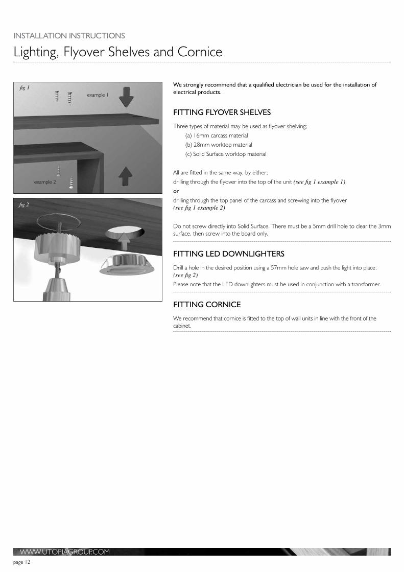
We strongly recommend that a qualified electrician be used for the installation of electrical products.
FITTING FLYOVER SHELVES
Three types of material may be used as flyover shelving;
(a) 16mm carcass material
(b) 28mm worktop material
(c) Solid Surface worktop material
All are fitted in the same way, by either;
drilling through the flyover into the top of the unit (see fig 1 example 1)or
drilling through the top panel of the carcass and screwing into the flyover (see fig 1 example 2)
Do not screw directly into Solid Surface. There must be a 5mm drill hole to clear the 3mm surface, then screw into the board only.
FITTING LED DOWNLIGHTERS
Drill a hole in the desired position using a 57mm hole saw and push the light into place. (see fig 2)Please note that the LED downlighters must be used in conjunction with a transformer.
FITTING CORNICE
We recommend that cornice is fitted to the top of wall units in line with the front of the cabinet.
or
example 2
example 1
fig 2
fig 1

WWW.UTOPIAGROUP.COMpage 13
Tall Units
Fixing Spacers
Back rail
Back panel
5mm drill
10mm drill
fig 2
fig 3
fig 4
FITTING A TALL GLASS SHELF DISPLAY UNIT AND ALL OTHER TALL UNITS
With either drawers or cabinet.
Drill the fixing holes in the back of the unit as follows:
a In the top and bottom sections of the unit, mark the positions of the two fixing holes as shown (see figs 1 and 2). b In the bottom section of the unit mark the positions of the two holes (see fig 2). Also note drilling method (see figs 3 and 4). c Once the hole positions have been marked, open up the hole in the 8mm back to10mm, to accommodate the cover cap. (see fig 4).
Once the unit has been positioned level (using a spirit level on all sides), push the supplied fixing screws through the Ø5mm holes until they touch the wall. Gently tap the screw heads to enable the screw points to mark the fixing points on the wall.
Remove the unit from its position and drill the wall in the positions you have just marked. If you are attaching the unit to a plasterboard wall, please ensure you use the correct fixings (not supplied).
Replace the unit into the desired position and use the screws provided to fix it to the wall through the back panel, through the plastic spacers, and into the wall. Ensure the unit is still level in all directions. Insert the 10mm screw covers.
If you are fitting the drawer pack version of this unit, there will not be an 8mm back behind the drawer boxes, simply fix through the back rail which can be easily accessed by removing the drawers. See drawer pack information on page 5.
Once all units are in place they can be joined together (if applicable) by means of drilling and screwing through adjacent side panels. We suggest making fixing less obvious by drilling behind hinges and shelves.
fig 1

INSTALLATION INSTRUCTIONS
WWW.UTOPIAGROUP.COMpage 14
Modular Units
heig
ht d
eter
min
ed b
y cu
stom
er
1000
mm
1300
mm
1600
mm
XX
Y
X
X
X
X
Ceramic Single Drawer Unit Modular Wall Unit1000
Modular Wall Unit1300
Modular Wall Unit1600
Double/Single Drawer Units (Worktop/Mineralcast/Ceramic options)
Double/Single Base Units (Worktop/Mineralcast/Ceramic options)
a b c
The recommended height from the floor to the top of the basin shown above as Y, is 900mm
FITTING WALL HUNG BASE UNITS AND WALL UNITS
Wall hanging brackets need to be fixed to the carcass if supplied separately. The brackets should be fixed the correct way up by knocking four prongs into the holes at the rear of the carcass. Ensure that the securing pin is knocked into place, (see fig 1).
Draw a line along the length of the wall, level with where the units are to be fitted at the desired height x (see fig 2).
Fix the brackets to the wall with appropriate plugs and screws for your wall type (not supplied).
The units then simply hook onto the wall fixed brackets. Adjustment to gain a level surface is as follows,
A - Adjust this to pull the cabinet into the wall
B - Adjust this to move the cabinets up or down (see fig 1);
Pull the cabinets tightly in against the wall using the adjustment screws on brackets. It is important to ensure you have sufficient support for the weight of pottery and unit plus contents when fitting wall hung units.
Once all units are in place they can be joined together by means of drilling and screwing through adjacent side panels. We suggest making fixing less obvious by drilling behind hinges and/or loose shelves, (see fig 3).
A securing screw should then be fitted through the back of the unit, through the fixed back rail of the cabinet (where available) and into the wall, this will help to stabilise the unit, (see fig 3).Now that all the units are securely fixed, ensure that all the back panels that were removed earlier are slid back into position before proceeding further, (see fig 3). Please note that many back panels are double-sided and therefore have a different finish on either side. Always check that you slide the panel in with the correct finish facing forwards.
For all units with a fixed back panel we advise that you drill a 10mm hole through the back panel and then fit a stabilising screw though the back rail of the cabinet into the wall. The 10mm hole can be covered with one of the caps supplied or if positioned appropriately, by the loose shelf of the unit, when applicable (see fig 4).Handles for wall units are to be fitted by the installer on location according to the customers requirements.
Units should be fitted by professional installers.
fig 3
fig 2
level line
securing pin
removeableback panel
back rail
Ain +out
up +down B
TOP OF UNIT
fig 1
Back PanelBack Rail
10mm drill
Wall
fig 4
INSTALLATION INSTRUCTIONS
WWW.UTOPIAGROUP.COMpage 15
Modular Units
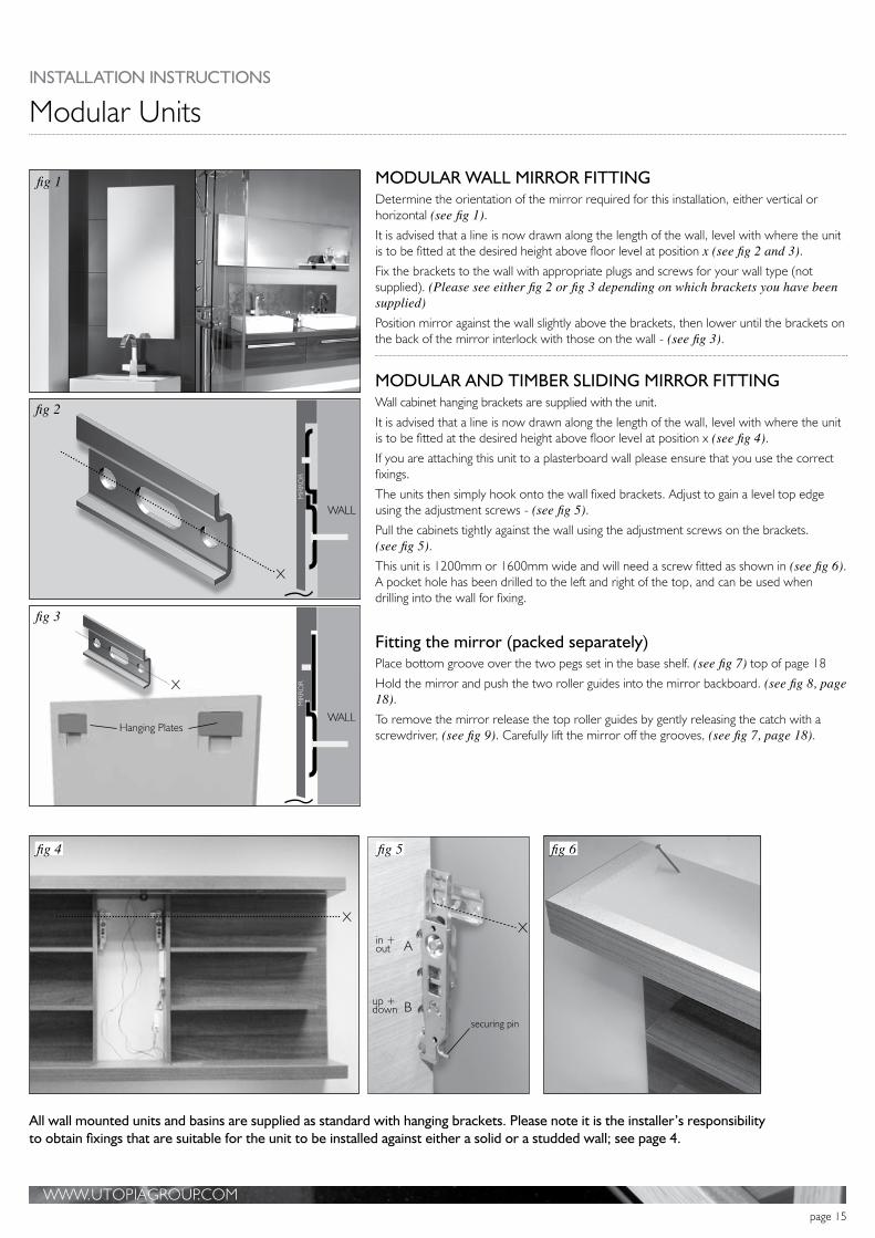
All wall mounted units and basins are supplied as standard with hanging brackets. Please note it is the installer’s responsibility to obtain fixings that are suitable for the unit to be installed against either a solid or a studded wall; see page 4.
MODULAR WALL MIRROR FITTING Determine the orientation of the mirror required for this installation, either vertical or horizontal (see fig 1).It is advised that a line is now drawn along the length of the wall, level with where the unit is to be fitted at the desired height above floor level at position x (see fig 2 and 3). Fix the brackets to the wall with appropriate plugs and screws for your wall type (not supplied). (Please see either fig 2 or fig 3 depending on which brackets you have been supplied)Position mirror against the wall slightly above the brackets, then lower until the brackets on the back of the mirror interlock with those on the wall - (see fig 3).
MODULAR AND TIMBER SLIDING MIRROR FITTINGWall cabinet hanging brackets are supplied with the unit.
It is advised that a line is now drawn along the length of the wall, level with where the unit is to be fitted at the desired height above floor level at position x (see fig 4). If you are attaching this unit to a plasterboard wall please ensure that you use the correct fixings.
The units then simply hook onto the wall fixed brackets. Adjust to gain a level top edge using the adjustment screws - (see fig 5).Pull the cabinets tightly against the wall using the adjustment screws on the brackets. (see fig 5).This unit is 1200mm or 1600mm wide and will need a screw fitted as shown in (see fig 6). A pocket hole has been drilled to the left and right of the top, and can be used when drilling into the wall for fixing.
Fitting the mirror (packed separately)Place bottom groove over the two pegs set in the base shelf. (see fig 7) top of page 18
Hold the mirror and push the two roller guides into the mirror backboard. (see fig 8, page 18). To remove the mirror release the top roller guides by gently releasing the catch with a screwdriver, (see fig 9). Carefully lift the mirror off the grooves, (see fig 7, page 18).
fig 1
fig 3
fig 2
WALL
WALL
MIR
ROR
MIR
ROR
X
X
X
X
securing pin
Ain +out
up +down B
fig 4 fig 5 fig 6
Hanging Plates

WWW.UTOPIAGROUP.COMpage 16
Modular Unit Mirror Door Handles and Door Hinge Adjustment MIRROR CABINET HANDLE FITTING
Please ensure all components are fitted in accordance with the diagram (see fig 1). Please fit hand tight only using a manual screwdriver. Do not overtighten as this may cause damage to the mirror door.
DOOR ADJUSTMENT
When adjustment is necessary to the doors, follow these directions (see fig 2): W - Lift this clip to release the door from the carcass
X - Adjusts the door’s horizontal position
Y - Adjusts the door’s vertical position
Z - Adjusts the in/out position of the door.
FITTING A MIRROR DOOR ON TO A UNIT
Remove the hinges from the units by lifting the tab underneath the hinge indicated by position W in the diagram (see fig 2).Place the hinges on to the glass doors by locating them in to their housing (fig 3 B) and rotating them forward until they lock in to place.
We advise that the hinge plates fitted are loosened off to allow easy fitting of the door.
Offer the door back up to the unit and clip the hinges back in to place on the unit.
On full mirror units please ensure when fitting the mirror there is no misalignment with the three mirror hinges to reduce the risk of stress upon the hinge and glass.
Once the door is in the correct position re-tighten the hinge plates to the cabinets and carry out final adjustment (see door adjustment and fig 2).Removing the hinge from glass door - (see fig 5). a. Insert a small flat headed screwdriver underneath the release catch situated inside the hinge.
b. Rotate the blade of the screwdriver through 90º.
c. Close the hinge, thus releasing it from the bracket.
It is vitally important that all doors are adjusted correctly, as over a period of time the stresses caused by misalignment can result in failure of the bond between the hinge plate and the glass surface, and your guarantee will become invalid.
SOFT CLOSE HINGE MECHANISM, REMOVAL AND RE-FITTING
1. This is supplied ready fitted to one of the hinges on the unit. Remove this to gain access to the hinge adjustment screws by sliding the soft close mechanism off the hinge, towards the door, as shown in the diagram (see fig 6).
2. To re-fit the mechanism, simply locate the metal tab (see fig 7 b) and the two hooks (see fig 7 c) inside the small hole on the hinge (see fig 8 d) and push forward and down until it clicks in to place.
Metal Pull Handle
Black Rubber Grommet
Hole in Mirror
White Plastic Washer
Fixing Screw
PLEASE DOUBLE CHECK BLACKRUBBER WASHER HAS BEEN FITTED
Y
ZX
W
c
door
fig 1
fig 2
fig 4
fig 5
fig 8
fig 3
B
XY
cb d
Z W
fig 6
fig 7
fig 7 fig 8 fig 9

WWW.UTOPIAGROUP.COMpage 17
Modular Units
FITTING THE MODULAR SQUARE PROFILE LAMINATE WORKTOPS - 1006MM, 1206MM, 1606MM LENGTHNote: Utopia as standard provides 2 brackets with each 1006mm, 1206mm and 1606mm worktop purchased separately to cover any possible installation. Dependent upon installation arrangement and number of worktops used, you may find that some brackets are not required.
If you are installing a fascia box and/or drawer unit along with the worktop(s) (see fig 1) and refer to page 14 of these instructions.
50MM LAMINATE WORKTOPSUse the Nylon Sleeve Insert, specially designed for use with 50mm laminate worktops, when fitting a worktop mounted tap.
Drill a small pilot hole at the centre of tap position.
Drill part way from under side a hole of 52-54mm Diameter (see fig 3). Then drill a 35mm hole from the top which will accommodate your tap. Insert the nylon sleeve. Use a quality silicon seal around both hole cuts and insert sleeve and fit tap.
INSTALLATION OF A WORKTOP ON ITS OWN OR AS THE LOWER WORKTOP OPTION SEEN IN FIG. 1Work out the desired height on the wall of the shelf location and mark out where the brackets are going to be. We advise that the brackets are set approximately 300mm in from the ends of the shelf (see fig 2).Making sure the brackets will be level, screw the brackets to the wall using suitable fixings.
BASIN WASTE RECOMMENDATION
A standard 32mm P trap or bottle trap can be accommodated in all washbasin unit installations. an in-line trap, or an extendable waste connector can be accommodated in all washbasins.
ADJUSTING A SOFT CLOSE DRAWER BOX
Drawer boxes are factory installed and should not need to be adjusted. However, if adjustment is required, pull the drawer box out and remove the Utopia branded plastic cap. This will reveal the two adjustment screws. Use one of the screws to raise and lower the drawer box (see fig 4 A) and the other (see fig 4 B) to skew it left and right.Large drawer units have a fixing bracket, located in the centre of the drawer box on the underside, that needs to be slackened off before adjustment and re-tightened after.
If you need to remove a drawer box, lift up and away from the drawer runners.
To replace the drawer box, fully extend the drawer runners, place the drawer box onto them and close the drawer. The box will clip itself in to place upon closing (see fig 5).To remove drawer front from the side turn screw (see fig 4 C).
ADJUSTING A CURVED FRONTED DRAWER
If you have the Encurva unit with a curved drawer front, please note that the drawer runners are different for this drawer box. To remove this drawer box from the unit pull the drawer out to see the underside, squeeze the two catches and the box will lift away. To replace put the box onto the runners and close the drawer which will engage the catches. Always check that the catches have engaged safely, if not the drawer box may fall away from the unit.
300mm
fig 1
fig 2
fig 3
35mm hole
tap
52-54mm hole
Nylon sleeve
A
C
B
fig 4
fig 5

WWW.UTOPIAGROUP.COMpage 18
INSTALLATION INSTRUCTIONS
Encurva Modular Furniture
Before installing an Encurva ceramic/Mineralcast unit you need to remove the transit support from the top of the unit. Cut through the support at the “V” mark and release the 2 cams at point X.
FITTING THE BASIN
Note with Encurva full and short-height units which have two doors or a drawer, and ceramic or Mineralcast basins, the basin needs to be bolted to the wall first, using the wall bolts and washers provided. If fixing to a studded wall, suitable fixing must be used (not supplied). (see fig 1).
When the basin is fixed to the wall the bottom edge must be at 90° to the wall as this will have to line up with the furniture being fitted, (see fig 2).
FITTING THE WALL HANGING BRACKETS.
Draw a line along the length of the wall, level with where the units are to be fitted at the desired height x (see fig 3/4).
Fix the brackets to the wall with appropriate plugs and screws for your wall type (not supplied).
When the wall brackets are fixed, adjust the hanger to its upper most point and hook onto the wall brackets and adjust up and back until it fits against the under side of the basin.
Adjustment to gain a level surface is as follows (see fig 3);
A - Adjust this to pull the cabinet into the wall (see fig 3) - A B - Adjust this to move the cabinets up or down (see fig 3) - B
Pull the cabinets tightly in against the wall using the adjustment screws on the brackets.
A stabilising screw can be fitted through the backboard inside the pipe box (see fig 5).
When installing units with a worktop above them a securing screw should be fitted through the back of the unit, through the fixed back rail of the cabinet (where available) and into the wall, which will help to stabilise the unit (also see page 14).For Door and Drawer Adjustment please see pages 16 and 17.
A 16mm side filler panel is supplied with an offset curved unit which is installed next to the side wall (see fig 6).
fig 1
fig 2
fig 1Underside of basin
Fixing Bolt secured to wall
The basin must be fixed at 90° to the vertical
Stabilising Screw
Nylon Washer
Nut
fig 4
fig 5
fig 6
level lineAin +out
up +down B
TOP OF UNITfig 3
V
X

WWW.UTOPIAGROUP.COMpage 19
Halo Units
1200 HINGED DOOR MIRROR UNIT Mirror door can be either left hand or right hand.
Fitting the cabinet to the wall,
Remove the door from the unit, care needs to be taken due to the weight of the mirror door panel
Note: the door hinges are fitted the reverse way to a normal hinged door (see fig 2) - the hinge back plate is fitted to the door not the unit side panel, to release the hinge and door depress the button at the rear of the hinge body (see fig 2), to remove the door take the weight of the door and release the hinges working from the bottom up. To re-fit start with clipping the top hinge first.
Fit cabinet to the wall using the standard cabinet hangers which are pre-fitted to the unit (see fig 4), also see page 14 for full instructions on how to fit the wall bracket and how to mount and adjust the cabinet.
1200 MIRROR DRAWER UNITFitting this unit requires the front mirror panel to be removed from the unit, care needs to be taken due to the weight of the mirror panel.
Remove the front mirror panel from the top and bottom drawers boxes (Note the middle drawer stays with the front mirror panel).
Start with the bottom drawer box (fig 2), Insert a cross bladed screwdriver into the catch release mechanism on the drawer box side and turn clockwise (fig 3), ensure that when you remove the screwdriver from the catch that it remains in the open position, this may require the front mirror door panel being pulled away from the drawer box slightly, until the top drawer box has been released.
Once all the drawer boxes sides have been released, pull the mirror panel away from the cabinet.
Fit cabinet to the wall using the standard cabinet hangers which are pre-fitted to the unit (see fig 4), also see page 14 for full instructions on how to fit the wall bracket and how to mount and adjust the cabinet.
Once the cabinet has been fitted to the wall securely and adjusted, push the mirror panel back into the drawer boxes, ensuring that the lock mechanism on each drawer box has been fully engaged and are in the closed position,
You should hear an audible click as the catches engage, carefully pull open the mirror panel to ensure all catches have fully engaged before passing off.
For drawer box adjustment refer to page 5 and 18.
fig 1
fig 1 fig 2
fig 2
fig 3
fig 4
fig 3
Cabinet
Depress button to release hinge from backplate
This drawer box stays with the front mirror panel when removed.
Top and bottom drawer boxes stay in the unit
Cabinet
INSTALLATION INSTRUCTIONS

WWW.UTOPIAGROUP.COMpage 20
TWIN BASE UNIT 650MM - 1200MM Draw a line along the length of the wall for the wall brackets (fig 2), the line is approx. 30mm below worktop height, ensure that the line is drawn level.
Measure between the gables ‘Y’ in (see fig 2) so that the wall brackets are fitted just to the inside of the gable
Fix the brackets to the wall by aligning the centre of the top holes in the bracket to the line X (see fig 2), fix bracket with appropriate plugs and screws for your wall type (not supplied). Ensure brackets fit just inside the gables (see fig 3). After the wall brackets are fitted to the wall:
Remove both drawer boxes before fitting the base unit to the wall.
Open and remove the main drawer by lifting the drawer up and off runners.
Push the top drawer so that it opens and lift off the runners.
Hook the base unit onto the brackets (see fig 3) ensuring that the arm on the unit clips behind the an’-jump spring on the wall bracket.
To adjust the unit level and square to the wall - adjust the brackets as follows.
A - to move the cabinet up or down
B - to pull the cabinet into the wall.
Once unit has been adjusted level the basin and taps can be fitted.
Fit 2 stretcher brackets equally spaced (see fig 4) to the rear of the unit, level brackets with the gable ends which will support the rear of the basin when fitted.
Re-fit drawer boxes starting with the push to open first.
Re-fit the main drawer, if drawers need adjusting in height or position - refer to page 5 for details on how to adjust.
To square the drawer front to the base unit side:
Open the main drawer, slide the cover plate at the front of the drawer box support rail backwards (see fig 5), to revel an orange adjusting nut, turn nut either clockwise or anti-clockwise to level the drawer front to the side gable.
If support rail needs to be removed fully, remove drawer box from unit, at the rear of the support arm a plastic tab needs to be depressed then pull arm upwards to remove from rear panel, fold the arm inwards across the drawer front, the arm can then be pulled from the drawer front.
For fitting and fixing a basin refer to page 40.
QUBE UNIT DRAWER BOXES.To remove a Qube drawer box from the unit runners, pull the drawer box out and remove the covers from each drawer side. Then by lifting the catches on each side as shown. (See fig 6 A), and release from its runner.
Please note: When refitting ensure the runner has engaged fully at the back of the drawer box, as this will prevent the box closing correctly.
Qube drawer box front adjustment see (fig 6 B). The base drawer has a gallery rail fitted to each side, this allows adjustment to the side gable of the unit and the back of the drawer front (fig 7 A). Make adjustment by twisting the round rail clockwise or anti-clockwise, this will tilt the drawer front back and forth to give a parallel fit to the side. Should you need to remove this rail, first remove box from unit, at the back were the rail fits into place, press at the point (fig 7 B).
Halo and Qube Units
Recommended height 870mm
X
Y
A
B
Fit 2 stretcher brackets equally spaced
level with gable ends
fig 1
fig 2
fig 3
fig 4
fig 5
fig 6 fig 7
A - Lift to remove
from drawer runners
C - Remove the drawer front
A
B - Raise or lower the drawer front
B

WWW.UTOPIAGROUP.COMpage 21
Halo Units
SIDE CABINET Open and remove the main drawer by lifting the drawer up and pull off runners.
Push the top drawer so that it opens and lift off the runners.
To fit wall brackets and how to mount and adjust cabinet refer to page 20.
Fit and fix worktop or basin into position, refer to page 40 for full fittng instructions.
After worktop or basins have been fitted re-fit drawers.
For drawer adjustment refer to page 5.
CLOAKROOM CABINETOpen and remove the main drawer by lifting the drawer up and pull off runners.
To fit wall brackets and how to mount and adjust cabinet refer to page 14.
Fit and fix basin into position, refer to page 40 for full fitting instructions.
After worktop or basins have been fitted re-fit drawers.
For drawer adjustment refer to page 5.
To square the drawer front to the base unit side:
Open the main drawer, slide the cover plate at the front of the drawer box support rail backwards (see page 20 fig 5), to revel an orange adjusting nut, turn nut either clockwise or anti-clockwise to level the drawer front to the side gable.
If support rail needs to be removed fully, remove drawer box from unit, at the rear of the support arm a plastic tab needs to be depressed then pull arm upwards to remove from rear panel, fold the arm inwards across the drawer front, the arm can then be pulled from the drawer front.
Cabinet hangers
Cabinet hangers
INSTALLATION INSTRUCTIONS

WWW.UTOPIAGROUP.COMpage 22
i-Line Fitted and Freestanding Furniture
i-LINE 50MM SIDE PANELS WITH FITTED FURNITURE
50mm tops and sides are fitted flush with the back of the units with almost no overhang around the sides and to the front fascia.
See pages 3 and 4 for installing base units.
There are two ways of installing 50mm side panels with fitted furniture.
1. With a 50mm side panel and an internal filler panel (see fig 1)
Or
2. With an external filler panel and 50mm side panel (see fig 2)
FITTING 50MM SIDE PANELS WITH AN INTERNAL FILLER PANEL AGAINST A WALL
Measure the filler panel and cut to the required width. Should the wall be out of square - reduce the depth of the 50mm side panel to allow for installation (see fig 3 A).
Screw a block to the back of the filler panel and screw the 50mm side panel to the cut edge of the filler panel (see fig 3 B)
Slide all 3 parts into position (see fig 3 C) and secure by screwing through the base unit D.
FITTING 50MM SIDE PANELS WITH AN EXTERNAL FILLER PANEL AGAINST A WALL
Measure and mark the filler panel and cut to the required width. Screw the filler panel to the 50mm side panel (see fig 4 A)
Slide both parts into position (see fig 4 B) and secure by screwing through the base unit C.
fig 1 fig 2
A
B
BC
D
fig 3
A
B
C
fig 4

WWW.UTOPIAGROUP.COMpage 23
i-Line Wall and Frameless Mirror Unit
i-Line Modular Units
FITTING WALL UNITS
See page 9 of these instructions.
FITTING AN i-LINE FRAMELESS MIRROR UNIT
The frameless mirror is held onto the backboard with an integrated 50mm side panel with two keyhole grommets. Remove the mirror by carefully lifting it up and away from the back-board and put to one side.
Put the Backboard into position and fix to the wall using appropriate fixings, (see fig 1).
Replace the mirror onto the backboard before fixing the 50mm flyover panel.
Screw the 50mm side panel near the front through the top and bottom panels using 3” screws and cover caps (supplied), (see fig 2) and (see fig 2A).
FITTING SUGGESTION
To help fitting we suggest that you fit i-Line wall configurations in the following order:
1. Wall units and 50mm side panel (see fig 3 A).
2. 50mm i-Line shelf that runs under the units (see fig 3 B).
3. i-Line mirror unit with 50mm side panel (see fig 3 C).
4. 50mm i-Line flyover that runs over the units (see fig 3 D).
I-LINE MODULAR UNITS
See page 14 for the fitting of wall hung modular units.
Twin units will need to be screwed together. The 50mm x 100mm base rail is screwed from the under side of the units with the 2 ½” screws supplied. Use the 1 ¼” screws to fix into the 50mm side panels. The 1” screws are to screw the two units together. All screws can now be capped. FIx the worktop in the usual manner.
fig 1
fig 2
fig 2a
see also fig 2a below
fig 3
AA
B
C
D
front edge
screw position
cent
re o
f pan
el
25mm
50mm mirror side panel
INSTALLATION INSTRUCTIONS

WWW.UTOPIAGROUP.COMpage 24
Symmetry Furniture
FITTING SYMMETRY MODULAR BASE UNITS AND FITTED/FREESTANDING BASE UNITS
It is advised that a line is drawn along the length of the wall, level with where the units are to be fitted at the desired height above floor level. The space between the floor and the unit is 175mm when using a plinth or as required for a modular unit. Draw the line shown as x (see fig 1) onto the wall.
Fix the brackets to the wall with appropriate plugs and screws for your wall type (not supplied).
The units then simply hook onto the wall fixed brackets. Adjustment to gain a level surface is as follows,
A - Adjust this to pull the cabinet into the wall
B - Adjust this to move the cabinets up or down (see fig 2);
Pull the cabinets tightly in against the wall using the adjustment screws on brackets. It is important to ensure you have sufficient support for the weight of pottery and unit plus contents when fitting wall hung units.
Once all units are in place they can be joined together by means of drilling and screwing through adjacent side panels. We suggest making fixing less obvious by drilling behind hinges and/or loose shelves, (see fig 3).
A securing screw should then be fitted through the back of the unit, through the fixed back rail of the cabinet and into the wall on a base unit, this will help to stabilise the unit (see fig 5 point 4).
FITTING SYMMETRY WORKTOPS/SOLID SURFACE
Please refer to pages 36-41 for instructions on fitting Worktops and Taps.
fig 3
fig 1
level line
securing pin
Ain +out
up +down B
TOP OF UNITfig 2
fig 4
6 in/out
4
fig 5

WWW.UTOPIAGROUP.COMpage 25
Symmetry Furniture
All units are fitted with extra leg sockets during manufacture. When installed next to a WC unit a straight plinth is supplied (see fig 1) so you will need to remove the leg sockets from the front curve of the unit before installation. To do this, insert a small flat-headed screwdriver into the centre section and carefully lever out the centre pin. The bracket can now be easily removed (see fig 2). Refer to page 6 for WC unit installation instructions.
DECORATIVE END PANELSDecorative End Panels are attached by drilling pilot holes and are fixed with the screws provided from inside the cabinet into the side panel. We suggest making fixing less obvious by drilling behind hinges and/or loose shelves.
Decorative end panels are supplied with 8mm locating dowels which when pushed into the predrilled holes will locate with the unit being installed, with the exception of a WC unit and any Symmetry unit that has a decorative panel adjacent to the side wall (see fig 6).
Should this unit be fitted into an alcove always install the wash basin unit first ensuring that units decorative side panel is fitted against the side wall. If the wall is out of square and narrower at the back, cut the decorative side panel down to allow the front to meet the side wall. The filler panel would then be fitted between the WC units decorative panel and the opposite side wall. The worktop will need to be trimmed from the WC end to allow for fitting.
FITTING SIDE PANELS WITH AN EXTERNAL FILLER PANEL
Measure and mark the filler panel cut to the required width. Screw the filler panel to the 16mm side panel (see fig 3 A).
Slide both parts into position (see fig 3) and secure by screwing through the base unit - (see fig 3 B).
FITTING SYMMETRY PLINTHS
Insert one end of the plinth into the groove of the side panel. Carefully bend around the unit legs and ease into the groove on the opposite side panel.
Please note that Symmetry WC units have a standard plinth arrangement. Please refer to page 6 for fitting instructions.
PLINTH LIGHTING
THESE SHOULD BE FITTED BY A QUALIFIED ELECTRICIAN.
LED plinth lights are fitted either around the top of the flexible plinth (see fig 4), or under the base of the unit (see fig 5). Transformers etc. can be concealed behind the plinth or at the back of the unit.
fig 1
fig 6
fig 3
fig 4
fig 5
lights fixed to plinth
lights fixed to underside of unit
B
A
fig 2
INSTALLATION INSTRUCTIONS
Only cut top when the wall goes narrower at back corner
Cut side filler and top to this endCut away panel
at the back which will give a better fit to the front

WWW.UTOPIAGROUP.COMpage 26
Timber Units
FITTING TIMBER MODULAR AND FREE-STANDING UNITSPlease refer to page 3 and 4 of these instructions for how to fit base cabinets. For instructions on adjusting a door or soft-close drawer see page 5 and page 16.
PLINTH INSTALLATION (when required)The plinth is supplied at the correct length for your unit. It is held in place by four magnetic catches on the underside of your unit - (see fig 1). Fix these into place using the round-headed screws before you install the unit into place as access to the rear of the unit is difficult.
FITTING A TIMBER ACCESSORY SHELFWe advise that a line is drawn along the length of the wall level with where the shelf is to be fitted. Fix the brackets to wall in the correct position, using appropriate fixings for the type of wall. The shelf simply slides onto the brackets and is held in place using locating screws from underneath the shelf (see fig 2 and 3). More than two brackets are supplied with longer shelves.
We suggest applying a bead of good quality silicon along the top back edge of the shelf to enhance a secure fit once the shelf is finally pushed into place (see fig 2).
BACK VIEW OF UNIT
BACK VIEW OF PLINTH
fig 1
fig 2 fig 3
SLIDE ONTO RODS THEN INSERT FIXING
SCREWS
UN
DER
SID
E O
F SH
ELF
WWW.UTOPIAGROUP.COMpage 27
INSTALLATION INSTRUCTIONS
Downton
fig 1 fig 2
fig 3
fig 5fig 4
fig 6
Basin Support shelf
Fit with overflow to the front
10mm space
Front
slacken screws
to adjust support
shelf
place a 2nd screw to fix shelf
permanently
fig 7
apply silicon within hatched areas
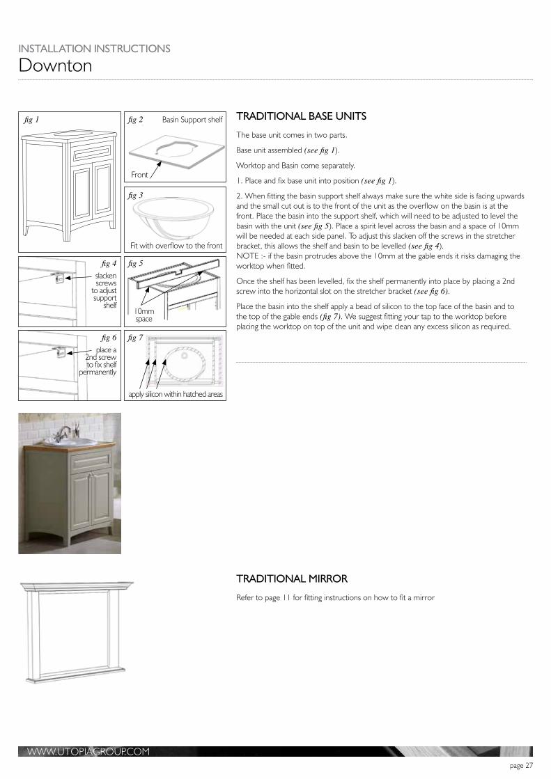
TRADITIONAL BASE UNITS
The base unit comes in two parts.
Base unit assembled (see fig 1).
Worktop and Basin come separately.
1. Place and fix base unit into position (see fig 1).
2. When fitting the basin support shelf always make sure the white side is facing upwards and the small cut out is to the front of the unit as the overflow on the basin is at the front. Place the basin into the support shelf, which will need to be adjusted to level the basin with the unit (see fig 5). Place a spirit level across the basin and a space of 10mm will be needed at each side panel. To adjust this slacken off the screws in the stretcher bracket, this allows the shelf and basin to be levelled (see fig 4). NOTE :- if the basin protrudes above the 10mm at the gable ends it risks damaging the worktop when fitted.
Once the shelf has been levelled, fix the shelf permanently into place by placing a 2nd screw into the horizontal slot on the stretcher bracket (see fig 6).
Place the basin into the shelf apply a bead of silicon to the top face of the basin and to the top of the gable ends (fig 7). We suggest fitting your tap to the worktop before placing the worktop on top of the unit and wipe clean any excess silicon as required.
TRADITIONAL MIRROR
Refer to page 11 for fitting instructions on how to fit a mirror

WWW.UTOPIAGROUP.COMpage 28
This range of furniture is supplied assembled and can be placed in position for installation to start. Any electrical work must be completed by a qualified electrician. Mirror transformers could be set into the wall plaster behind the mirror, or in the recess on top of the unit keeping it to the back. Note should the plinth panels supplied be required? By turning the unit upside down these can be screwed into the back of the unit legs. The wall and mirror units will be fitted using the wall hanging fittings found behind the back panel. (See page 8. & 11). Tall units and intermediate high units are also fitted with wall hangers. When a fixed back is fitted to a cupboard a stabilising screw into the wall near the base which will ensure the unit stays tight against the wall. In some floor standing units a stretcher plate can be used to support the unit sides, also a fixing through the back top rail into the wall. (See fig 4, page 3). Work tops are held with stretcher plates or silicon, locate the top position and fix as needed. Solid surface tops with an under slung ceramic basin have a supporting shelf which will need to be levelled and fixed. (See fig 1-7, page 27). Drawer box removing and adjusting. (See page 5).
Door removing and adjusting. (See page 9). Bath panels come complete should the plinth panels supplied be required these can be screwed to the back of each panel before panels are fitted. End panels can be fixed with stretcher plates (see page 29). Bath panels.
Bath side panel can be pushed into place using keku clips (see fig 3, page 29).
Downton

WWW.UTOPIAGROUP.COMpage 29
LEG EXTENSION
SOCKET
KEKU CLIPS
LEG
LEG CLIP
BOLT
DOWELCAM
COMPONENT IDENTIFICATION
CORNER SUPPORT
‘L’ BRACKET
MAGNET CATCH AND PLATE
ONLY USE ROUND-HEADED SCREWS WITH THE CATCH
Bath Panels
Including the Dualelle, Definity and Definity Freestanding baths.
Please note:The bath being fitted must have a wooden batten fitted under the bath rim to hold the bath panel clips. In the event that the bath being fitted does not have any timber for these clips, the installer will need to fit timber under the bath rim as necessary. Depending on tiling, panels may be required to be trimmed to walls.
Bath panels are not supplied with plinth return corner.
Remove all protective film from panels before fixing together. Note in some instances the pre-drilled holes will be covered by the panels finish. These holes will need to be reinstated.
Wall fixings are not supplied - a suitable fixing for the wall must be used by the installer.
All cut panels must be sealed with a high quality silicon sealant.
Baths with a 350mm high panel and fitted plinth – the plinth must line up with the furniture which has a 175mm plinth. When using a 500mm high panel with a plinth, set the height required for the bath being fitted. See page 6 for fitting a plinth. Bath panel plinths are not supplied with plinth returns.
INSTALLATION HELP NOTESThe bath panel top rail is set under the rim of the bath, with the desired amount of rail showing and fixed to the bath timber. All bath panels are fitted under this rail (see fig 1)
END PANELImportant - the End Panel should be fitted before fitting the Side Panel.
When the bath has an end panel, fix this with the ‘L’ brackets to the wall and the timber under the bath rim.
Two black Keku clips can be fitted to the front edge to allow the bath side panel to be removable (see fig 2).
SIDE PANELThe three black Keku clips can be fixed to the timber under the bath rim to give the required finish for the bath panel. The two ‘L’ brackets will be used as stops at the side walls – fit about 300mm from the top of the panel (see fig 3).We suggest panel legs are fixed to the floor, this will avoid sliding when plinth is fitted.
WALL
WALL
END PANEL
SIDE PANEL
L BRACKET AS A STOP
300mm
fig 1
fig 3
fig 2
INSTALLATION INSTRUCTIONS

WWW.UTOPIAGROUP.COMpage 30
Definity Bath Panels
fig 5
CUTOUT FOR OVERFLOW
POSITION THE BATH TO ALLOW AN EQUAL DISTANCE AROUND THE BATH RIM AND TOP RAIL
FREE-STANDING DEFINITY TOP RAIL
DEFINITY FITTED BATH - CORNER OR RECESSED INSTALLATIONRemove all protective film from panels before fixing together. Note in some instances the pre-drilled holes will be covered by the panels finish. These holes will need to be reinstated.
NOTE when fitting a top rail this is to be done first. See top rail notes below, (see fig 3, 4 and 5).Level the bath to ensure the panels will not have to be cut to the floor when they are installed.
The side panel set of three parts D, E & F are held together with the cams and bolts provided. Panels D & E have two magnetic catch plates to be fixed at the top in the pre-marked positions. The black Keku clips are for extra support and are fitted at each end where the panels meet the end panel (see fig 1) or a wall (see fig 2). The pre-marked positions are set away from the edge as panels E and D are also used with return panels as shown in (see fig 1).
Fix the end return panel as shown (see fig 1) using the stretcher plates provided. The three side panels will then push into place. (see fig 2), also see notes on page 29.
TOP VIEW OF DEFINITY BATH PANELS FITTED INTO A CORNER
TOP VIEW OF DEFINITY BATH PANELS FITTED INTO A RECESS
fig 1
fig 2
WALL
WALL
WALL
WALL
WALL
END PANEL
C
D
D
F
F
E
E
POSITION THE BATH TO ALLOW AN EQUAL DISTANCE AROUND THE BATH RIM AND TOP RAIL
TOP RAIL OPTIONS CUT TO SIZE ON INSTALLATION AT POINTS A & B
A
B
CUTOUT FOR OVERFLOW
POSITION THE BATH TO ALLOW AN EQUAL DISTANCE AROUND THE BATH RIM AND TOP RAIL
TOP RAIL OPTIONS CUT TO SIZE ON INSTALLATION AT POINTS A & B
A
B
fig 3
fig 4
CUTOUT FOR OVERFLOW
CUTOUT FOR OVERFLOW

WWW.UTOPIAGROUP.COMpage 31
INSTALLATION INSTRUCTIONS
Definity Freestanding Bath Panels
CAM AND BOLT FIXING
MAGNET CATCH PLATES
MAGNET CATCH PLATES
MAGNET CATCH PLATES
MAGNET CATCH PLATE
MAGNET CATCH PLATE
CAM AND BOLT FIXING
CORNER SUPPORTCORNER SUPPORT
KEKU CLIPS
KEKU CLIPS
CAM AND BOLT FIXING
DETACHABLE FRONT PANELS
DETACHABLE FRONT PANELS
A
B
C
D
E F
TOP VIEW OF FREE-STANDING DEFINITY BATH PANELS
fig 1
DEFINITY FREESTANDING BATHRemove all protective film from panels before fixing together. Note in some instances the pre-drilled holes will be covered by the panels finish. These holes will need to be reinstated.
Bath top rails are pre-marked for fixing to the timber blocks around the underside of the bath rim. Position the bath to allow an equal distance around the bath rim and top rail (see fig 5, page 30).PLEASE NOTE the bath will have to be raised to accommodate the thickness of the top rail.
The underside of this rail is pre-marked and the magnet catches and stretcher plates will align with the panels.
BEFORE FIXING THE BATH, THE TOP RAIL must be fitted first and allow for cutting around the tap. Then the bath may be levelled at a height to avoid cutting panels to the floor.
Panels A, B & C are fixed together with the cams/bolts provided. Fix one magnet catch plate at the top centre of panel B and one magnet catch plate to the back of panel A & C. Then one stretcher plate at the top front of panels A & C.
Panels D, E & F are fitted as shown (see fig 1).

WWW.UTOPIAGROUP.COMpage 32
fig 1
A
A
BC
E
C
C
F
F
D
D
2mm gapKeku hook clip
Keku clipsBracket fixed to
top rail only
Top Rail
2mm gap
Symmetry Bath Side and End Panels
SYMMETRY BATHS
Please note - remove all protective film from panels before fixing them together.
Ensure the under side of this bath rim is fitted at a height which will give the required clearance for the panels and/or a bath end storage unit when fitting.
BATH SIDE PANELS WITH A TOP RAIL
The top rail should be fitted first around the under side of the bath rim with the desired amount of rail showing and fixed to the timber under the bath rim.
FITTING BATH SIDE AND END PANELS
Fix the 3 bath side panels together with the blocks and screws provided ensuring there is a 2mm space between each panel (see fig 1 A). Fit the adjustable foot at the base of the centre panel (see fig 1 B), to support the panels. Fit the Keku clips as shown (see fig 1 C), ensuring that they line up correctly on the top rail and panels. Once in place, fix an L bracket to the under side of the top rail as a stop support to the bath centre panel (see fig 1 E). Fit the end panel to the side panel using the angled brackets which are screwed at the pre-marked positions (see fig 1 D). Fit the two L brackets to the wall approximately 100mm from the floor level where the back of the side and end panel final position will be (see fig 1 F). Slide the assembled panels onto the keku clips from the end until they positively engage.
NOTE: DEPENDING ON TILING, PANELS MAY NEED TO BE TRIMMED FOR A BETTER FIT TO THE WALL.
x 28
C x 1C x 1
C x 3 C x 3 C x 3
D x 2B x 1
F x 2
COMPONENT IDENTIFICATION

WWW.UTOPIAGROUP.COMpage 33
fig 1
A
A
B
E
C
C
2mm gap
2mm gap
Symmetry Bath Panel
SYMMETRY BATHS.
Please note - remove all protective film from panels before fixing them together.
Ensure the under side of this bath rim is fitted at a height which will give the required clearance for the panels and/or a bath end storage unit when fitting.
BATH SIDE PANELS WITH A TOP RAIL.
The top rail should be fitted around the under side of the bath rim with the desired amount of rail showing and fixed to the timber under the bath rim.
FITTING BATH SIDE PANEL BETWEEN 2 WALLS
When fitting a side panel set between two walls fasten them together with the blocks and screws provided ensuring there is a 2mm space between each panel (see fig 1 A)Fit the adjustable foot at the base of the centre panel (see fig 1 B), to support the panels. Fit the Keku clips as shown in (see fig 1 C), ensuring that they line up correctly on the top rail and panels. Once in place, fix an L bracket to the under side of the top rail as a stop support to the bath centre panel (see fig 1 E). Fit the two L brackets to the wall approximately 100mm from the floor level where the back of the side panel final position will be (see fig 1 F). Slide the assembled panels onto the Keku clips until they positively engage.
If you wish to remove this panel for maintenance purposes we recommend that you use a suction pad similar to a glazers pad placed in the approximate location of the Keku clips and ease off from one end.
Keku clip
Keku clip
Bracket fixed to top rail only
Top Rail
F
F
INSTALLATION INSTRUCTIONS

WWW.UTOPIAGROUP.COMpage 34
A
A
B
E
C
D
C
C
C
2mm gap
2mm gap
Symmetry Bath Panel with End Storage Unit
SYMMETRY BATHS
Please note - remove all protective film from panels before fixing them together.
Ensure the under side of this bath rim is fitted at a height which will give the required clearance for the panels and/or a bath end storage unit when fitting. Check that the floor is level so it doesn’t impede the bath end storage unit door.
BATH SIDE PANELS WITH A TOP RAIL.
The top rail should be fitted first around the under side of the bath rim with the desired amount of rail showing and fixed to the timber under the bath rim.
FITTING BATH SIDE PANEL WITH END STORAGE UNIT
Fix the 3 bath side panels together with the blocks and screws provided ensuring there is a 2mm space between each panel (see fig 1 A), and the 5mm feet are to the floor, add two self adhesive stops to the top of each panel these afford enough clearance to allow the storage unit door to open freely. The storage unit will be fitted with a 10mm high foot which allows the unit door to clear the floor when opened.
Fit the adjustable foot at the base of the centre panel (see fig 1 B), to support the panels. Fit the Keku clips as shown (see fig 1 C), ensuring that they line up correctly on the top rail and panels. Fix an L bracket to the underside of the top rail (see fig 1 D), which will act as a stop. Fit another L bracket to the wall approximately 100mm from the floor level where the back of the side panel final position will be (see fig 1 E). Slide the End Storage unit into position. Do not fix it at this stage.
Slide the assembled panels onto the Keku clips until they positively engage.
Adjust the End Storage unit until the door is in the desired position.
The End Storage unit can then be screwed to the top rail from the inside of the unit and fixed to the back wall.
Keku clip
Transit support. This should be removed prior to installation by cutting at the pre-marked “V” cuts
Keku clip
Bracket fixed to top rail only
Top Rail
fig 1
WWW.UTOPIAGROUP.COMpage 35
Granite and Marble Worktops
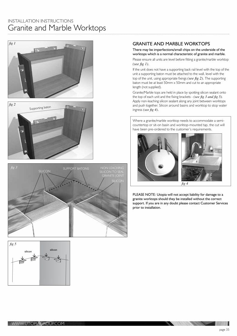
GRANITE AND MARBLE WORKTOPSThere may be imperfections/small chips on the underside of the worktops which is a normal characteristic of granite and marble.
Please ensure all units are level before fitting a granite/marble worktop (see fig 1).If the unit does not have a supporting back rail level with the top of the unit a supporting baton must be attached to the wall, level with the top of the unit, using appropriate fixings (see fig 2). The supporting baton must be at least 50mm x 50mm and cut to an appropriate length (not supplied).
Granite/Marble tops are held in place by spotting silicon sealant onto the top of each unit and the fixing brackets - (see fig 3 and fig 5). Apply non-leaching silicon sealant along any joint between worktops and push together. Silicon around basins and worktop to stop water ingress (see fig 4).
Where a granite/marble worktop needs to accommodate a semi-countertop or sit-on basin and worktop-mounted tap, the cut will have been pre-ordered to the customer’s requirements.
PLEASE NOTE: Utopia will not accept liability for damage to a granite worktops should they be installed without the correct support. If you are in any doubt please contact Customer Services prior to installation.
SILICON
NON LEACHING SILICON TO SEAL
GRANITE JOINT
SUPPORT BATONSSILICON
fig 3
fig 4
fig 1
fig 2Supporting baton
fig 5silicon
silicon
INSTALLATION INSTRUCTIONS

WWW.UTOPIAGROUP.COMpage 36
Geo
GEO DRAWER UNITWhen fitting this unit draw a line along the length of the wall, level with where the units are to be fitted at the desired height - X (see fig 1 and fig 2). Fix the brackets to the wall with appropriate plugs and screws for your wall type (not supplied). The units then simply hook onto the wall fixed brackets.
Adjustment to gain a level surface as follows.
A. Adjust this to pull the cabinet into the wall.
B. Adjust this to move the cabinets up or down (see fig 1)Pull the cabinets tightly in against the wall using the adjustment screws on the brackets and hangers (as shown in fig 1 and fig 2).For extra support a screw can be fitted into the wall through the hole in the cabinet hanger (as shown in fig 1).
The stretcher plate fitted at the base of the unit also needs to be fixed to the wall, this will give stability to the unit and secure it from being lifted up and away from the wall.
For drawer adjustment see page 5. GEO INTEGRA AND GEO SOLID SURFACE
Geo Integra, Geo Solid Surface with or without a basin. Also the Free Flow basin. The height from floor to the top of the basin is recommended at 900mm (see fig 3). Geo Free Flow top and basin. This is supplied with a template which will positon the wall fixing points. An overall height from floor to the surface of 900mm. fixing to wall with appropriate plugs and screws for your wall type. (Not supplied). Mark a line along the wall as X in (fig 3). This line to suit the top holes in the main fixing brackets. Three brackets for the 1600mm, two brackets for the 1200mm and 800mm this also has two stretcher brackets fitted either side of the tap hole, which will support the work top.(fig 4). Fixing with the appropriate plugs and screws for your wall type. (Not supplied). You sometimes are supplied with two chrome towel brackets, these fit beneath the worktop to give easy access for hanging towels if required (fig 5). Also note they are NOT worktop supporting. For fitting a basin into the worktop follow the template supplied with your basin and other notes are on page 40. Underslung basins cannot be fitted into this work top.
fig 2
TOP OF UNIT
level line
securing pin
Ain +out
up +down B
fig 1extra screw to be fitted
fig 3
fig 4
fig 5
recommended height of 900mm from floor to top of basin
recomended 100mm
1200 and 800 Geo-stone
stretcher brackets

WWW.UTOPIAGROUP.COMpage 37
INSTALLATION INSTRUCTIONS
Tap Holes
Warning - For your information and guidance Utopia’s Solid Surface products are not suitable for use in a shower enclosure.
DRILLING FOR TAPS IN THE WORKTOPMark the position of the taps on the worktop using the manufacturers recommended guidelines (see fig 1).Drill through the work surface with a hole saw using the marked positions (see fig 2).Sand all raw edges (both the 3mm surface material and the substrate) applying a slight radius and a smooth finish to the edge.
Apply good quality silicon sealant to all sanded surfaces and smooth out to ensure a full even coverage including the tap hole (see fig 3).Fit the taps following the manufacturers instructions.
DRILLING A TAP HOLE IN A MINERALCAST CLOAKROOM WASHBASIN
Choose the location of the tap and mark the centre point of the hole. Drill from the top face ensuring you have space inside the cavity for the tap fittings.
Using a hole saw for cutting tap holes, cut through the Gelcast surface. If fitting a Utopia tap cut a 35mm hole. If using any other tap please refer to the manufacturer’s fitting guidelines (see fig 4).
50MM LAMINATE WORKTOPSUse the Nylon Sleeve Insert, specially designed for use with 50mm laminate worktops, when fitting a worktop-mounted tap.
Drill a small pilot hole at the centre of the tap position.
Drill part way from under side a hole of 52-54mm diameter (see fig 5). Then drill a 35mm hole from the top which will accommodate your tap. Insert the nylon sleeve.
Use a quality silicon seal around both hole cuts and insert sleeve and fit tap (see fig 5).
fig 1
fig 2
fig 3
fig 4 fig 5
35mm hole
WORKTOP MOUNTED TAP
tap
52-54mm hole
Nylon sleeve

WWW.UTOPIAGROUP.COMpage 38
Solid Surface and Laminate Worktops
GUIDE FOR THE INSTALLATION OF SOLID SURFACE PRODUCTS
IMPORTANT
These instructions must be followed when installing Solid Surface Products.
We recommend that you use the following tools:
Portable router - To do all cuts and cross cuts wherever possible. Belt Sander - for finishing rough or cut edges.
Orbital Sander - for finishing rough or cut edges. Hole Saw - for cutting out tap holes
We DO NOT recommend that you use the following:
Jigsaw - Do all cuts and cross cuts with a router wherever possible. Spade and Auger type drill bits - Always use hole saws.
However, a jigsaw may be used only if a brand new downward cutting blade is used and these instructions are strictly adhered to.
PLEASE READ THESE INSTRUCTIONS CAREFULLY BEFORE COMMENCING WORK
All Solid Surface tops are packed together with a relevant fitting pack and are identified by a label which appears on the front of the box and the rear of the packaging.
It is advised that fitting commences from a corner wherever possible, ensuring correct spacing should a corner filler be used. It is also advised that all doors and facias are removed prior to fitting to avoid unnecessary damage occurring.
If the Worktop has become slightly bowed during storage it can be pulled straight during the installation process.

WWW.UTOPIAGROUP.COMpage 39
INSTALLATION INSTRUCTIONS
Worktops
FITTING A WORKTOPPosition the worktop on the units and push up against the wall to enable you to mark and measure for cutting (see fig 1).If the worktop needs scribing to the wall contours do so using a compass and pencil (see fig 2).We suggest that an allowance of 10mm is made to accomodate a worktop overhang on an exposed worktop edge or show ends.
Use a belt sander to remove the final bit of material and to eliminate small chips or saw kerfs, the latter is most important. If necessary hand finish the cut edge using sandpaper (see fig 3).Seal all cut or raw edges (including those that meet the wall) using good quality silicon sealer ensuring that a full coverage is obtained (see fig 4).Screw the worktop down to the cabinets, making sure the screw does not penetrate too deep into the substrate of the worktop (see fig 5). Change screw size from 1” to ¾ “ (see fig 5).Finally run a small bead of silicon between the join of the worktop and the wall (see fig 6).
Stretcher plateMax ¾” Screw
Front railMax 11/2” Screw
fig 1
fig 3
fig 4
fig 5
fig 6
fig 2

WWW.UTOPIAGROUP.COMpage 40
Worktops
Sanded laminate
Substrate
fig 3
fig 4
fig 1 fig 2
silicon sealant
1
fig 6 fig 7
AB
C
INSTALLING A WASHBASIN INTO A LAMINATE OR SOLID SURFACE WORKTOPWhen cutting out for a washbasin a template must be used. These will be provided by the pottery manufacturer and will be one of two types, a semi-counter top type (see fig 1) or an inset vanity basin (see fig 2). Do not attempt to fit an underslung basin into any laminated worktop as the substrate is unsuitable for this. Note only solid surface or granite tops will be suitable.
Following the pottery manufacturers instructions, lay the template in the desired position and draw around it allowing for a 12mm overhang (see fig 1).Make the cut outs using a portable router if possible.
However, if a jigsaw is used please make sure all small chips and saw kerfs are removed by sanding the edges producing a slight radius to the 3mm surface (see fig 3).All worktops must be cut at points A, B and C and sealed with a good quality silicon sealant as illustrated (see fig 4) to accommodate a Utopia basin. This will allow the basin to fit closely to the fascia of the unit below.
For all other pottery follow the manufacturer’s instructions.
Once the basin is in position apply a bead of silicon sealer around the joint between the pottery and furniture. This is very important to prevent water ingress.
Fit the basin following the manufacturers instructions.
Note - Do not cut a square corner in Solid Surface worktops. They must have at least a 5mm radius (see fig 5).
FIXING CERAMIC SLABTOPS, SIT-ON, SEMI-COUNTERTOP OR MINERALCAST WASHBASINS
Basins can be fixed directly to the unit by using a good quality silicon sealant around the top of the unit and the back of the slabtop. This will bond the slabtop to the top of the unit and wall to give extra support (see fig 6). All sit on and semi countertop basins are bonded to the worktop with a good quality silicon sealant
BASIN WASTE RECOMMENDATION
A standard 32mm P trap or bottle trap can be accommodated in all washbasin unit installations with the exception of the 740mm and 1040mm ceramic washbasin single drawer unit where we recommend the use of a flexible waste fitting as shown (see fig 7).fig 5
Cut to basin size

WWW.UTOPIAGROUP.COMpage 41
INSTALLATION INSTRUCTIONS
Worktops
fig 1 FITTING A SOLID SURFACE APRON STANDARD AND SHORT PROJECTION
Position the fascia into the slot ensuring that the fascia is tight against the front edge of the slot.
Ensure that the apron remains central on the fascia, (see fig 1), and the distance that the top edge of the apron sits above the top edge of the fascia (a) is equal on both sides (see fig 2).Apply a bead of good quality silicon to the top edge of the apron.
Align the fixings on the fascia with the fixings on the cabinet and push the fascia onto the cabinet until it locks into place.
Apply a small amount of upwards pressure to the apron until it fits flat against the underside of the worktop and temporarily stick it in place using several pieces of masking tape (see fig 3).Wipe off any excess silicon with a clean cloth.
We recommend that you leave the silicon a minimum of 12 hours to set before removing the masking tape.
SOLID SURFACE SHELVES AND SHELF SUPPORTS
1 Firstly, ensure that the small adjustment bolt remains seated in the back of the bracket before fixing (see fig 4).
2 Mark the positions of the bracket holes on the wall, relative to the size of the shelf. Take care to ensure the holes are level with each other using a spirit level. Drill into the wall at the marked points. Insert the Rawlplugs or other appropriate fixing.
3 Check that the nut and bolt are loosely in position in the back of the bracket (see fig 4), and screw the brackets to the wall (see fig 5).
4 When both brackets are securely fixed place the shelf centrally between the clasps and turn the adjustment screws on the underneath of the brackets until the shelf is securely held in place (see fig 6).
Fascia
Correct position - Cowl is seated centrally
a a
aa
Incorrect position - Cowl is not seated centrally
fig 2
fig 3
fig 4 fig 5 fig 6

WWW.UTOPIAGROUP.COMpage 42
Worktops50mm Decorative Floating Shelf with Adjustable Support
Draw a horizontal line on the wall at the desired height X (see fig 1).Fix the concealed shelf supports to the wall using appropriate fixings for the wall type (not supplied).
Once the bracket is in position, final adjustment can be achieved as follows:
Height - adjust A via slots
Inclination - adjust using adjusting screws (B) that press on the rear plate.
Lateral - adjust by lifting the support pin (C) and moving left or right.
We suggest applying a bead of good quality silicon along the top back edge of the shelf to enhance a secure fit once the shelf is finally pushed into place. (see fig 2).
X
fig 1
ABBC
Shelf
Spirit Level
fig 2

Painted Products Fitting InstructionsPlease read instructions carefully before commencing fitting
WWW.UTOPIAGROUP.COMpage 43
Painted Products Fitting Instructions - Index
43-1
Please read instructions carefully before commencing fitting
CARE AND MAINTENANCE INSTRUCTIONSSpills should be removed immediately using a clean cloth.
Furniture should be regularly dusted with a soft cotton or micro-fibre cloth.
For more thorough cleaning, occasionally wipe your furniture with a soft cloth dampened with a mild detergent solution.Surfaces should be thoroughly dried with a lint free cloth to prevent watermarks.
Under no circumstances should solvent cleaning agents (such as nitro-based thinners, acetone, nail polish remover or similarproducts) be used.
Some furniture polishes are unsuitable for use on painted surfaces and can degrade the paint. Always ensure that polishesare suitable for end use.
Never use abrasive cleaning agents or cloths (e.g. linen cloths, paper towels etc) as these will scratch.
Glass or mirrored panels should be cleaned using a non-solvent based glass cleaner and a soft cloth, carefully avoidingcontact with painted sections.
If your furniture becomes stained, scratched or chipped, or suffers other damage we recommend professional help is soughtto restore it.
Failure to follow the above guidelines will invalidate your guarantee.
Electrical Connections
All electrical connections need to be installed by a qualified electrician.
Lighting below cabinets is all LED and include appropriate driver.
Discuss with your electrician switching and position requirements for wall hung basin cabinets.
Shaver socket should be wired into appropriate circuit.
Switch on shaver socket is for under cabinet lighting, however you can discuss with your electrician alternativemethods and position for switching under cabinet lighting
Single Wall Mirror Cabinets. 43-2
Twin Wall Mirror Cabinets. 43-3
Wall Hung Cabinets. 43-4
Twin Wall Hung Cabinets. 43-5
Drawer Adjustment with decorative trim. 43-6
Floor Mounted Cabinets. 43-7Basins, Worktops, Wall Mirrors and Framed Panels. 43-8Bath & Filler panels. 43-9Tall wall cabinets. 43-10
Mirror cabinet - electrical connections. 43-11
NOTE: - WHEN FITTING PAINTED PRODUCTS A POT OF PAINT IS SUPPLIED WITH EACH ORDER

WWW.UTOPIAGROUP.COMJN9255 Sept09 V1.1page 44
1. Remove cabinet from box.
PLACE UNIT ON DUST FREE SURFACE - TAKE CARE NOT TO SLIDE AND SCRATCH PAINT SURFACE
2. Wall brackets are supplied with the unit and fit between gables, measure between gables for correct dimension ‘A to A’.
3. Mark a line at the desired height for the 2 wall brackets (X to X) and ensure it’s level.
4. When fitting hanging brackets to wall ensure correct fixings are used for wall type (not supplied).
5. Remove doors from cabinet by un-clicking hinges fig 1 also remove internal shelf .
CARE NEEDS TO BE TAKEN WHEN REMOVING SHELF NOT TO MARK PAINTED CABINET SIDES.
6. Wind brackets out, using top screw of bracket that can be accessed from the rear or inside of the cabinet.
7. Lift cabinet up and hang onto wall brackets.
8. Level cabinet up using the bottom screw in the hanger, accessed from inside cabinet, once level wind the hanger in pullingcabinet back to wall, not too tightly at this stage.
9. In the centre of back panel there is a hole to fit an anti-lift screw (not supplied), mark wall through hole, remove cabinet fromwall and fit appropriate wall fixing.
10. Re-hang cabinet and check level, wind hangers back in, pulling unit tightly against wall and fit an anti-lift countersunk headedscrew through cabinet back, into wall fixing (not supplied).
11. Re-fit shelf - CARE AGAIN NEEDS TO BE TAKEN WHEN RE-FITTING SHELF NOT TO MARK CABINET SIDES.
12. Re-fit doors to cabinet and adjust as below or alternatively see video clip. https://www.youtube.com/watch?v=56cqwMnKRz0
13. Fit cover caps supplied over hanger access holes.
SINGLE WALL MIRROR CABINETS
Hinge Removal
To remove hinge start with the bottom hinge.
1. Release catch at rear of hinge.2. Lift hinge off back plate.3. Then slide door forwards, repeat for other hinges.
(fig 1.)
1. Push hinge arm onto the mounting plate from the front (fig 2.).
2. The hinge arm is then pressed onto the mounting plate, until anaudible click is heard (fig 3.).
Once door has been fully fitted adjust hinges as below if required.
Re-fitting Hinge (fig 2.) (fig 3.)
Turn screw clockwisereduces door overlay ( - )
Turn screw anti-clockwise increases door overlay ( + )
Overlay adjustment Depth adjustment
Turn screw clockwiseWinds door in
Turn screw anti-clockwise Winds door out
Vertical Height adjustmentIn-line back-plate
+/-2mm
Height AdjustingScrew
Adjust screw at rear of back plate.
Clockwise to move door upwards
Anti-clockwise to lower door
Adjust both hinges by the same amount
XX
X X
145mmapprox.
705mmA A
43-2
For electricalconnections see
index page

WWW.UTOPIAGROUP.COMpage 45
TWIN WALL MIRROR CABINETS
1. Remove cabinet from box.
PLACE UNIT ON DUST FREE SURFACE - TAKE CARE NOT TO SLIDE AND SCRATCH PAINT SURFACE
2. Wall brackets are supplied with the unit 3off and fit between gables, measure between gables for correct dimension ‘A to A’.
3. Mark a line at the desired height for the 3off wall brackets (X to X) and ensure they are fitted level.
4. When fitting hanging brackets to wall ensure correct fixings are used for wall type (not supplied).
5. Remove doors from cabinet by un-clicking hinges see fig 1 also remove internal shelves.
CARE NEEDS TO BE TAKEN WHEN REMOVING SHELF NOT TO MARK PAINTED CABINET SIDES.
6. Wind brackets out, using top screw of bracket that can be accessed from the rear or inside of the cabinet.
7. Lift cabinet up and hang onto brackets.
8. Level cabinet using the 2 outer hangers, use the bottom screw in hanger accessed from inside cabinet, once level, adjustmiddle hanger till it meets wall bracket.
9. Wind the hanger back in pulling cabinet back to wall, not too tightly at this stage.
10. In the centre of back panel there is a hole to fit an anti-lift screw (not supplied), mark wall through hole, remove cabinet fromwall and fit appropriate wall fixing.
11. Re-hang cabinet and check level, wind hangers back in, pulling unit tightly against wall and fit an anti-lift countersunk headedscrew through cabinet back, into wall fixing (not supplied).
12. Re-fit shelf - CARE AGAIN NEEDS TO BE TAKEN WHEN RE-FITTING SHELF NOT TO MARK CABINET SIDES.
13. Re-fit doors to cabinet and adjust as below or alternatively see video clip. https://www.youtube.com/watch?v=56cqwMnKRz0
14. Fit cover caps supplied over hanger access holes.
Hinge Removal
To remove hinge start with the bottom hinge.
1. Release catch at rear of hinge.2. Lift hinge off back plate.3. Then slide door forwards , repeat for other hinges.
1. Push hinge arm onto the mounting plate from the front (fig 1.)
2. The hinge arm is then pressed onto the mounting plate, until anaudible click is heard (fig 2.).
Once door has been fully fitted adjust hinges as below if required.
Re-fitting Hinge (fig 1.) (fig 2.)
Turn screw clockwisereduces door overlay ( - )
Turn screw anti-clockwise increases door overlay ( + )
Overlay adjustment Depth adjustment
Turn screw clockwiseWinds door in
Turn screw anti-clockwise Winds door out
Vertical Height adjustmentIn-line back-plate
2mm
Height AdjustingScrew
Adjust screw at rear of back plate.
Clockwise to move door upwards
Anti-clockwise to lower door
Adjust both hinges by the same amount
145mm
X
705mm
X3x
Wall Brackets
5mmAnti lift hole
A A AA
43-3
For electricalconnections see
index page

WWW.UTOPIAGROUP.COMJN9255 Sept09 V1.1page 46
WALL HUNG CABINETS incl WITH DRAWERS
Fully open Close drawer 10 CMRaise drawer gently
and
Hanging Cabinet onto wall.1. Remove both drawers from cabinet where required as figs 1,2,3
Fitting wall BracketsRecommended height to top of basin is 900mm
1. Remove basin and draw a line approx. 50mm below cabinet gablesto give you the top hole centres in wall plate. X-X.
2. Wall brackets fit inside gables measure dimension ‘A ‘ fig 4 forinternal dimensions.
3. Wall bracket dimensions can be seen in fig 5.
4. When fixing wall brackets to wall ensure the correct wall type fixingsare used for wall type.
5. Once unit is level drill and fix through bottom rail to fix unit into place.
To remove cabinet from wall1. Remove drawers as above. (Figs 1 to 3).2. Support cabinet and depress the spring clip sufficiently to allow the arm to lift out of bracket fig 8.
Fig 8
Fig 9Re-Fitting drawersAs fig 9 and adjust as on page 6.
Fig 5 - Wall Bracket
36mm
52mm
Fig 4
X X
A
50mm
Note: - Recommend fixing wall hung cabinets to a solid wall, where an internal wall is used, it needs to be strengthenedsufficiently to take the fixings and weight of cabinet and basin.
Hanging Cabinets1. Fit unit to the wall by pushing the bracket arm into the wall
plate until anti-jump spring locks arm into place see fig 6.
2. Tighten unit up to the wall using screw ‘B’ fig 7, do not overtighten cabinet to the wall at this stage.
3. Level unit by adjusting screw ‘A’ fig 7(Anti-clockwise to lower unit - Clockwise to raise unit).
4. Once unit is in position tighten cabinet to the wall with screw‘B’ fig 7.
Bracket Arm
Fig 6
A
Fig 7
B
For Fitting Basins and Worktops see page 43-8
43-4
For electricalconnections see
index page
For Fitting Basins and Worktops see page 50

WWW.UTOPIAGROUP.COMpage 47
TWIN WALL HUNG CABINET WITH DRAWERS
Note: - Unit is supplied as 2 cabinets
Remove both cabinets from boxes
PLACE CABINETS ON DUST FREE SURFACE - TAKE CARE NOT TO SLIDE AND SCRATCH PAINT SURFACE
Fully open drawer Close drawer 10 CMRaise drawer gently and
pull out horizontally
1. Remove both drawers from cabinet as figs 1,2,3Note: - Drawer positions when removing drawers, drawers arehanded
Right Hand Wall Cabinet1. Offer cabinet up to left hand cabinet, ensure dowels in the middle gable as shown in
fig 8 - align dowels with the corresponding holes in the light panel in the right hand wallcabinet.
2. Adjust cabinet so that it is level with left hand cabinet.
3. Clamp the 2 units together and fix with 8 x30mm screws through pre drilled holes,2 holes through drawer runner and one in the hanger plate, an additional fixing can beplaced behind top 55mm rail if required.
4. Finally fix through bottom rails at back to stop any lateral movement.
5. Re-fit drawers as shown on page 3 - fig 9 and adjust drawer boxes shown on page 6.
Wall Brackets.1. Draw a line approx. 50mm below gable top, long
enough to cover both cabinets, this gives the top holepositions for the wall brackets.
2. Wall brackets fit inside the gables, measure dimension‘A’ fig 4 for the internal dimensions.
3. For wall bracket dimensions see fig 5
4. When fixing wall brackets to wall, ensure correctfixings are used for wall type (not supplied).
Fig 4
Fig
Note: - Recommend fixing wall hung cabinets to a solid wall, where an internal wall is used, it needs to be strengthenedsufficiently to take the fixings and weight of cabinets and basins.
Left Hand Wall Cabinet1. Fit Left Hand Cabinet 1��, lift and support cabinet, push bracket arm into the
wall plate until anti-jump spring locks arm into place fig 6.2. Lightly tighten cabinet up to the wall by turning screw ‘B’ fig 7, do not over
tighten cabinet to the wall at this stage.3. Level unit by turning adjusting screw ‘A ‘- fig 7
(Anti-clockwise to lower unit - Clockwise to raise unit).4. Once unit is in position tighten cabinet to the wall with screw ‘B’ fig 7.5. Fit 2 off 8mm dowels into 22mm RH panel at bottom, ready to accept RH cabinet
Bracket Arm
Fig 6
A
Fig 7
B
X X
A
58mm
50mm
36mm
52mm
Fig 5 - Wall Bracket
For Fitting Basins and Worktops see page 43-8
43-5
For electricalconnections see
index page
For Fitting Basins and Worktops see page 50

WWW.UTOPIAGROUP.COMJN9255 Sept09 V1.1page 48
Adjustment for Drawer Box with Decorative Trim SidesIncluding Drawer front removal and re-fitting
Horizontal Drawer front adjustment - fig 2
Depress lever beneath drawer box side and move drawer front horizontally asrequired adjustment range is +/- 1.5mm.
fig 2
DECORATIVE TRIM- Drawer sides - fig 1
On all drawer sides a decorative trim in a matching colour is fixed in place byuse of a magnetic strip.
To remove trim gently pull trim up and away from sides.
fig 1
Tilt adjustment for drawer box - fig 4
Locate screw on the inside of drawer side to rear of drawer box adjustmentrange is +/- 2mm.
fig 4
Vertical Drawer front adjustment - fig 3
Slacken screw 1 and adjust height as required by turning screw 2 adjustmentrange is +/- 2mm.
fig 3
Drawer Front Removal - fig 5
Depress the lever beneath the drawer side and lift drawer front upwards.
ReleaseLever
fig 5
Re-Fitting Drawer Front - fig 6
To re-fit drawer front engage tag on drawer clip into drawer side andpush drawer front into drawer box.
Once parts are fully engaged re-adjust drawer front as required.
fig 6
43-6

WWW.UTOPIAGROUP.COMpage 49
FLOOR MOUNTED CABINETS
1. Remove cabinet from box.
PLACE UNIT ON DUST FREE SURFACE - TAKE CARE NOT TO SLIDE AND SCRATCH PAINT SURFACE.
2. Remove doors (see below for hinge removal).
3. If removing shelf - CARE NEEDS TO BE TAKEN NOT TO MARK PAINTED CABINET SIDES.
Hinge Removal
To remove hinge start with the bottom hinge.
1. Release catch at rear of hinge.2. Lift hinge off back plate.3. Then slide door forwards , repeat for other hinges.
1. Push hinge arm onto the mounting plate from the front (fig 1.)
2. The hinge arm is then pressed onto the mounting plate, until anaudible click is heard (fig 2.).
Once door has been fully fitted adjust hinges as below if required.
Re-fitting Hinge (fig 1.) (fig 2.)
Turn screw clockwisereduces door overlay ( - )
Turn screw anti-clockwise increases door overlay ( + )
Overlay adjustment Depth adjustment
Turn screw clockwiseWinds door in
Turn screw anti-clockwise Winds door out
Vertical Height adjustment
Adjust screw at rear of back plate.
Clockwise to move door upwards
Anti-clockwise to lower door
Adjust both hinges by the same amount
1. Fit 2 stretcher brackets approximately as shown.
2. Fix unit back to wall using appropriate wall fixings (not supplied).
3. Fit basin as per page 43-7.
4. Re-fit doors as below, adjust as required.stretcherbrackets
43-7
For Fitting Basins and Worktops see page 43-8For Fitting Basins and Worktops see page 50

WWW.UTOPIAGROUP.COMJN9255 Sept09 V1.1page 50
WORKTOPS, BASINS, FRAME AND WALL MIRRORS
Slab Basin Fitting
(Recommend a solid wall or a strengthened wall to take weight of cabinet and basin).
1. Mark wall and prepare wall for the appropriate basin wall fixings fig - 1.
Fix basin through here withappropriate basin fixings
fig 1
fig 2
2. Run a bead of silicon around top of gables and against wall where basin is tofit and fit basin on top of gables fig - 2.
Fitting Sit on Basins
1. Ensure there is a sufficiently large enough hole to allow the waste to be fitted.
2. Apply a silicone bead around outer mounting surface on under side of basin.
3. Place basin onto worktop ensuring waste hole in basin and the worktop areinline.
4. Allow sufficient time for silicone to harden.
43-8
Stretcher brackets
Worktop Fitting
1. Where a worktop is being fitted onto a cabinet then extra support for the worktop is requiredat rear of unit, fit 2 stretcher brackets as shown or alternatively a batten can be used (notsupplied).
2. To fit brackets to the 20mm solid surface, then a 3mm pilot hole must be drilled beforefixing, ensure hole is deeper than the screw.DO NOT OVER TIGHTEN SCREWS WITH 20mm SOLID SURFACE MATERIAL.
3. Alternative fixing method for the worktop is to run a bead of silicon around the top surfaceto bed the worktop on to, this can be done in addition to above.
Mirrors and Framed Panels1. Mirrors and frame panels can be hung either portrait
or landscape.
2. Panels are hung using an appropriate wall fixing,hooked into the pre mounted suspension fitting onrear of mirrors and panels.
Key holesuspension
fixings

WWW.UTOPIAGROUP.COMpage 51
Note: When fitting bath panels, timber will be required under the bath rim to fix Keku clips to. In the event that the
bath does not have timber for the clips, the installer will need to fit timber to the under side of the bath rim as required.
1. When the bath has an end panel, fix the stretcher plate to the back wall and fit the Keku tounder side of bath fig 1.
2. Fit 2-off Keku clips to the front edge of the end panel as in fig 1, which allows the front bathpanel to be clipped to it.
Three Keku clips can be fitted to the timber under the bath rim so that the side panel can beclipped into position - fig 2.
Fixing bath panel directly to a wall,1. Fit stretcher plates to wall fig 3, these plates are to support bath panel when it has been
clipped into place fit the Keku clips as described in fig 2.
2. Once in bath panel has been clipped into place silicone panel to wall as required.
BATH AND FILLER PANELS
FITTING BATH PANELS.Bath panels can be fitted directly to either side wall or with a infill panel with a pilaster fitted between bath panel and the wall.
Fit stretcher plate approx. 300mm fromunderside to support bath end panel
Stretcher bracketfitted to timber
Fig 1.
Bath End Panel
Kekuclips
Fig 3.
Stretcher
Fig 4.
Infill panelwith PilasterFixing bath panel using a in-fill panel with pilaster.
1. Scribe infill panel into wall, allowing for a 2mm gap between Pilaster and Bath Panel fig 4.
Fit in-fill panel behind bath panel fig 5 and fix into position.
Once in panel has been clipped into place silicone panel to wall as required.
Fig 5.
43-9
Keku clips
Fig 2.
Fit tobath panel
Fit to undersideof bath

WWW.UTOPIAGROUP.COMJN9255 Sept09 V1.1page 52
xx
TALL CABINETS
1. Remove doors if fitted, see page 43-7.
2. Measure dimension ‘A’ fig 2 (brackets fit between gables).
3. Mark a line at the required height X- X
4. Fix the 2 wall plates to the wall using appropriate fixingsfor wall type, ensure distance between brackets allowthem to fit between the gables.
1. Mount cabinet onto wall plates and adjust level byturning screw ‘A’ accessed from top of cabinet, fig 2Note: - as ‘A’ is adjusted it will pull the cabinet into wall.
2. Where required re-fit doors see page 43-7 and adjust ifrequired.
Fig 1.
43-10
Height adjusting screwsFig 2.
‘A’

WWW.UTOPIAGROUP.COMpage 53
MIRROR CABINET - ELECTRICAL CONNECTIONS
All Electrical connections need to be installed by a qualified Electrician.
Lighting below cabinets is all LED and includes appropriate driver.
Discuss with your electrician switching and position requirements for wall hung basin cabinets.
Shaver socket should be wired into appropriate circuit.
Switch on shaver socket is for under cabinet lighting, however you can discuss with your electrician alternativemethods and position for switching under cabinet lighting
43-11

WWW.UTOPIAGROUP.COMJN9255 Sept09 V1.1page 54
Care and Maintenance Instructions
Spills should be removed immediately using a clean cloth.
Furniture should be regularly dusted with a soft cotton or micro-fibre cloth.
For more thorough cleaning, occasionally wipe your furniture with a soft cloth dampened with a mild detergent solution.
Surfaces should be thoroughly dried with a lint free cloth to prevent watermarks.
Under no circumstances should solvent cleaning agents (such as nitro-based thinners, acetone, nail polish remover or similar products) be used.
Some furniture polishes are unsuitable for use on painted surfaces and can degrade the paint. Always ensure that polishes are suitable for end use.
Never use abrasive cleaning agents or cloths (e.g. linen cloths, paper towels etc) as these will scratch.
Glass or mirrored panels should be cleaned using a non-solvent based glass cleaner and a soft cloth, carefully avoiding contact with painted sections.
If your furniture becomes stained, scratched or chipped, or suffers other damage we recommend professional help is sought to restore it.
Failure to follow the above guidelines will invalidate your guarantee.

utopia… naturally
WWW.UTOPIAGROUP.COMpage 55

FITT
INST
STA
ND
ARD
UFI - iDM JN 22955 - 08/16
Utopia Furniture Limited, Springvale Avenue, Wolverhampton WV14 0QLTel - 01902 406400 Fax - 01902 406401 Customer Services - 01902 406 402
Email - [email protected] www.utopiagroup.com
Proudly designed and manufactured in Britain