multipoint instantaneous fitting instructions
TRANSCRIPT
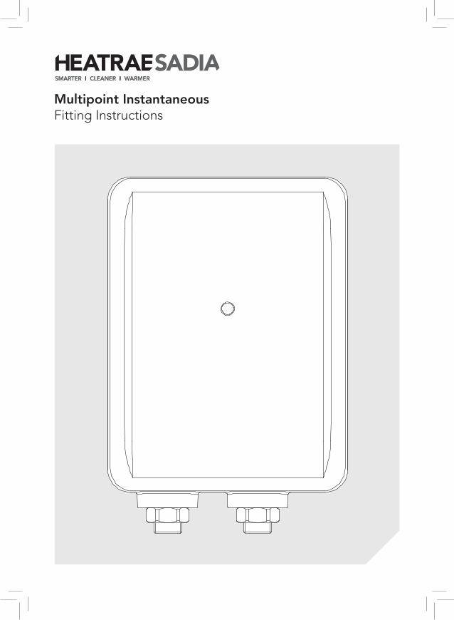
Multipoint InstantaneousFitting Instructions
This product can be used by children aged from 8 years and above and persons with reduced physical sensory or mental capabilities or lack of experience and knowledge if they have been given supervision or instruction concerning use of the product in a safe way and understand the hazards involved. Children shall not play with the product. Cleaning and user maintenance shall not be made by children without supervision. Children must be supervised to ensure they do not play with the product.
Contents
1. Introduction ...............................................................................................31.1 General ...............................................................................................31.2 Symbols used ......................................................................................31.3 Abbreviations .......................................................................................31.4 Liabilities .............................................................................................3
2. Safety .........................................................................................................42.1 General safety warnings .....................................................................42.2 Recommendations ..............................................................................42.3 Specific safety instructions ..................................................................4
3. Technical specifications ..........................................................................53.1 Technical data .....................................................................................53.2 Dimensions and connections ..............................................................53.3 Electrical Diagram(s) ...........................................................................5
4. Description of the product .......................................................................64.1 General description .............................................................................64.2 Operation principle ..............................................................................64.3 Main components ................................................................................6
5. Before installation ...................................................................................75.1 Installation regulations ........................................................................75.2 Installation Requirements ....................................................................75.3 Choice of location ................................................................................7
6. Installation .................................................................................................86.1 General ...............................................................................................86.2 Water Connections ..............................................................................86.3 Electrical Connections .........................................................................8
7. Commissioning .........................................................................................107.1 General ...............................................................................................107.2 Checklist before commissioning ..........................................................107.3 Commissioning procedure ..................................................................10
8. Operation ...................................................................................................108.1 General ...............................................................................................10
9. Troubleshooting ........................................................................................119.1 General ...............................................................................................11
10. Decommissioning ..................................................................................1110.1 Decommissioning procedure .............................................................11
11. Spare parts .............................................................................................12
Warranty ........................................................................................................14
3
1. Introduction
1.1 General
The following instructions are offered as a guide to the user and installer.
The installation must be carried out by a competent plumbing and electrical installer in accordance with Building Regulation G3 (England and Wales), Technical Standard P3 (Scotland) or Building Regulation P5 (Northern Ireland) and the Water Fitting Regulations (England and Wales) or Water Byelaws (Scotland).
1.2 Symbols used
In these instructions, various risk levels are employed to draw the user’s attention to particular information. In doing so we wish to safeguard the user, avoid hazards and guarantee the correct operation of the product.
WARNING
Risk of dangerous situation causing slight physical injury.
CAUTION
Risk of material damage.
Signals important information.
1.3 Abbreviations
` RCD – Residual current device ` MCB – Miniature circuit breaker
1.4 Liabilities
Manufacturer’s liability
Our products are manufactured in compliance with the requirements of the various applicable European Directives.
This product complies with the requirements of the CE marking directive.
In the interest of UK customers, we are continuously endeavouring to make improvements in product quality. All the specifications stated in this document are therefore subject to change without notice.
Our liability as the manufacturer may not be invoked in the following cases:
` Failure to abide by the instructions on using the product.
` Faulty or insufficient maintenance of the product.
` Failure to abide by the instructions on installing the product.
Installer's liability
The installer is responsible for the installation and the commissioning of the product. The installer must respect the following instructions:
` Read and follow the instructions given in the manuals provided with the product.
` Carry out installation in compliance with the prevailing legislation and standards.
` Perform the initial start-up and carry out any checks necessary.
` Complete the commissioning checklist. ` Explain the installation to the user. ` If maintenance is necessary, warn the user of
the obligation to check the product and maintain it in good working order.
` Give the instruction manual to the user.
Users liability
To guarantee optimum operation of the product, the user must respect the following instructions:
` Read and follow the instructions given in the manuals provided with the product.
` Call on qualified professionals to carry out installation and initial start-up.
` Get your installer to explain your installation to you.
` Have your required checks and services done. ` Keep the instruction manuals in good condition
and close to the appliance.
4
2.3 Specific safety instructions
WARNING
DO NOT operate the product if:
` Water ceases to flow during use. ` Water has entered inside the
product because of an incorrectly fitted cover.
` If the product is damaged.
(in all cases turn off mains power and isolate water supply)
2. Safety
2.1 General safety warnings
WARNING
` Only competent persons having received adequate training are permitted to work on the product and the installation.
` Do not tamper with the safety valve supplied.
` Before any work, switch off the mains supply to the product and water supply.
` Do not switch on if there is a possibility that the water in the product is frozen.
2.2 Recommendations
CAUTION
` Annual maintenance is recommended by a competent person.
5
Standards and approvals
` Complies with the requirement of EN 60335-2-35.
` Complies with European Community Directives (CE).
` Complies with UK water regulations, kiwa approved
3.2 Dimensions and connections
Dimensions
Height - 210mm Width - 160mm Depth - 104mm
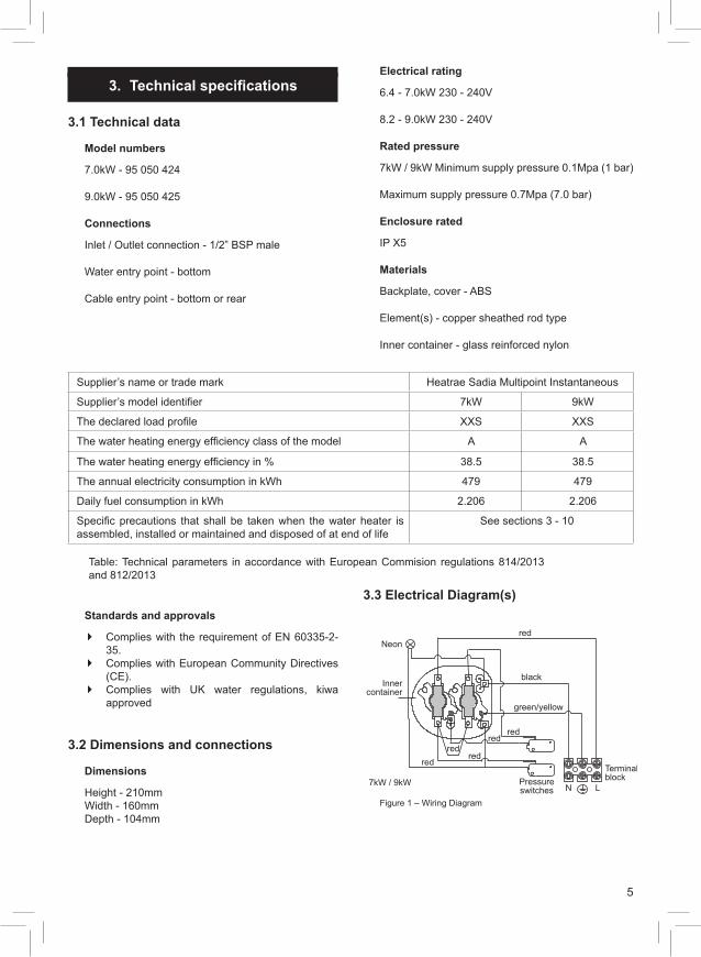
3.3 Electrical Diagram(s)
Neon
7kW / 9kW
Innercontainer
red
black
green/yellow
Pressureswitches N L
Terminal block
redred
redred
red
Figure 1 – Wiring Diagram
3. Technical specifications
3.1 Technical data
Model numbers
7.0kW - 95 050 424
9.0kW - 95 050 425
Connections
Inlet / Outlet connection - 1/2” BSP male
Water entry point - bottom
Cable entry point - bottom or rear
Electrical rating
6.4 - 7.0kW 230 - 240V
8.2 - 9.0kW 230 - 240V
Rated pressure
7kW / 9kW Minimum supply pressure 0.1Mpa (1 bar)
Maximum supply pressure 0.7Mpa (7.0 bar)
Enclosure rated
IP X5
Materials
Backplate, cover - ABS
Element(s) - copper sheathed rod type
Inner container - glass reinforced nylon
Supplier’s name or trade mark Heatrae Sadia Multipoint Instantaneous
Supplier’s model identifier 7kW 9kW
The declared load profile XXS XXS
The water heating energy efficiency class of the model A A
The water heating energy efficiency in % 38.5 38.5
The annual electricity consumption in kWh 479 479
Daily fuel consumption in kWh 2.206 2.206
Specific precautions that shall be taken when the water heater is assembled, installed or maintained and disposed of at end of life
See sections 3 - 10
Table: Technical parameters in accordance with European Commision regulations 814/2013 and 812/2013
6
4. Description of the product
4.1 General description
These heaters are of the closed outlet type (unvented pressure system) and are suitable for connection to normal cold water mains supply up to a maximum of 0.7MPa (7.0 bar) for 7 & 9 kW
4.2 Operation principle
The product is used to provide the user with hot water at point of use.
By turning on the tap water flows through the product which then switches the element on to heat the water.
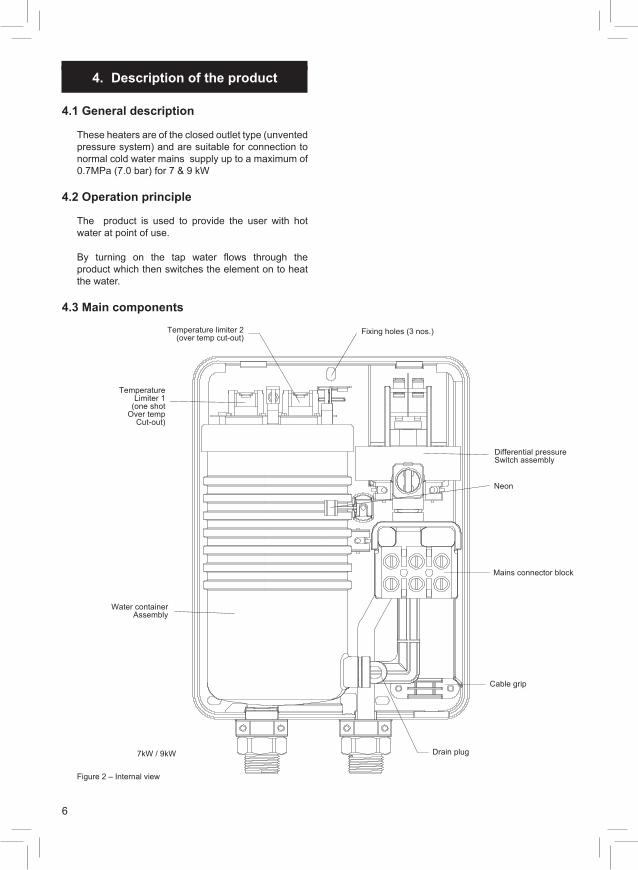
4.3 Main components
Fixing holes (3 nos.)
TemperatureLimiter 1
(one shotOver temp
Cut-out)
Cable grip
Drain plug7kW / 9kW
Differential pressureSwitch assembly
Mains connector block
Water containerAssembly
Temperature limiter 2(over temp cut-out)
Neon
Figure 2 – Internal view
7
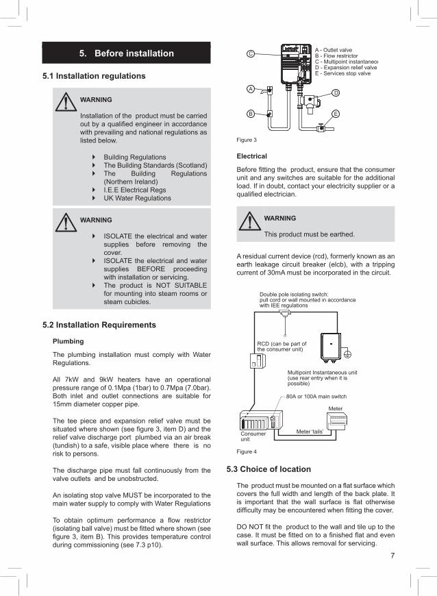
A - Outlet valveB - Flow restrictorC - Multipoint instantaneousD - Expansion relief valveE - Services stop valve
A
B
C
D
E
Figure 3
Electrical
Before fitting the product, ensure that the consumer unit and any switches are suitable for the additional load. If in doubt, contact your electricity supplier or a qualified electrician.
WARNING
This product must be earthed.
A residual current device (rcd), formerly known as an earth leakage circuit breaker (elcb), with a tripping current of 30mA must be incorporated in the circuit.
Multipoint Instantaneous unit (use rear entry when it is possible)
80A or 100A main switch
Meter
Meter ‘tails’Consumer unit
RCD (can be part of the consumer unit)
Double pole isolating switch:pull cord or wall mounted in accordancewith IEE regulations
Figure 4
5.3 Choice of location
The product must be mounted on a flat surface which covers the full width and length of the back plate. It is important that the wall surface is flat otherwise difficulty may be encountered when fitting the cover.
DO NOT fit the product to the wall and tile up to the case. It must be fitted on to a finished flat and even wall surface. This allows removal for servicing.
5. Before installation
5.1 Installation regulations
WARNING
` ISOLATE the electrical and water supplies before removing the cover.
` ISOLATE the electrical and water supplies BEFORE proceeding with installation or servicing.
` The product is NOT SUITABLE for mounting into steam rooms or steam cubicles.
WARNING
Installation of the product must be carried out by a qualified engineer in accordance with prevailing and national regulations as listed below.
` Building Regulations ` The Building Standards (Scotland) ` The Building Regulations
(Northern Ireland) ` I.E.E Electrical Regs ` UK Water Regulations
5.2 Installation Requirements
Plumbing
The plumbing installation must comply with Water Regulations.
All 7kW and 9kW heaters have an operational pressure range of 0.1Mpa (1bar) to 0.7Mpa (7.0bar). Both inlet and outlet connections are suitable for 15mm diameter copper pipe.
The tee piece and expansion relief valve must be situated where shown (see figure 3, item D) and the relief valve discharge port plumbed via an air break (tundish) to a safe, visible place where there is no risk to persons.
The discharge pipe must fall continuously from the valve outlets and be unobstructed.
An isolating stop valve MUST be incorporated to the main water supply to comply with Water Regulations
To obtain optimum performance a flow restrictor (isolating ball valve) must be fitted where shown (see figure 3, item B). This provides temperature control during commissioning (see 7.3 p10).
8
Connect the cold water supply pipe to the inlet of the product, this is a 1/2” BSP connection.
Fit top and bottom screws and secure the back plate to the wall ensuring that it is level.
Connect all other components as per figure 3. Turn the isolating stop valve on slowly and check for leaks in all pipe work, rectify as necessary.
Turn off the isolating stop valve.
6.3 Electrical Connections
WARNING
This product must be earthed.
The installation, supply cable and circuit protection must conform to the latest BS7671 ‘Requirements for electrical installations’ (IEE Wiring Regulations).
The Multipoint Instantaneous heater must only be connected to a 230/240V ac supply.
Before making any electrical connections within the installation, make sure that no terminal is live. If in doubt, SWITCH OFF the whole installation at the consumer unit or switch fuse (where fitted).
The Multipoint Instantaneous heater must be connected to its own independent electrical circuit.
Check that your consumer unit (main fuse box):
1. has a main switch rating of 80A or above.
2. has a spare fuse way which will take the fuse/mcb you need to fit - (see figure. 4). If so, you can wire the Multipoint Instantaneous direct to the spare fuse of your consumer unit via a suitably rated isolating switch- (see figure 4). Note that not all consumer units will accept a 35/40/45A sized fuse.
If point 1 and 2 are not achievable, the installation is not straight forward, since it could involve installing a new consumer unit to serve the whole house or just the Multipoint Instantaneous. You will need to call in your Regional Electricity
Company to check the circuit and make the connections to the meter or service connector block. They should also check the earth bonding of items in the vicinity.
A residual current device (rcd), formerly known as an earth leakage circuit breaker (elcb), with a tripping current of 30mA must be incorporated in the circuit.
6. Installation
6.1 General
After reading the previous sections in this booklet and choosing a good location for the product please install, paying attention to the following plumbing, electrical and commissioning sections.
Mounting
Preparation
Remove the fixing screw which holds the front cover onto the back plate of the product. Carefully remove the cover.
Fix the product heater loosely to the wall. The wallplugs provided are suitable for most brick walls (use a 6.5mm diameter masonry drill), but if your wall is plasterboard or soft building block you should use special wallplugs and an appropriate drill obtainable from most hardware stores.
6.2 Water Connections
Plumbing
Decide where to connect to the water mains for your feed to the product. Ensure that the pipe you have selected is not a gas pipe, a hot water pipe or from a cold water storage tank.
Cut the necessary pipe work to length, offer up to the installation before making any soldered joints. Ensure that the pipe is the correct length, as shortening it can be difficult once joints have been made.
An isolating stop valve MUST be incorporated to the main water supply to comply with Water Regulations
Assemble the installation before making any soldered joints. DO NOT use jointing compounds on any pipe fittings for the installation.
Remove the product before soldering the connections.
WARNING
DO NOT solder pipes or fittings within 300mm of the heater once the pipe work is located in the product as heat transfer can damage components.
It is essential to flush the pipe in order to clear debris, particles of solder and swarf.
Turn the water off after flushing using the isolating stop valve.
9
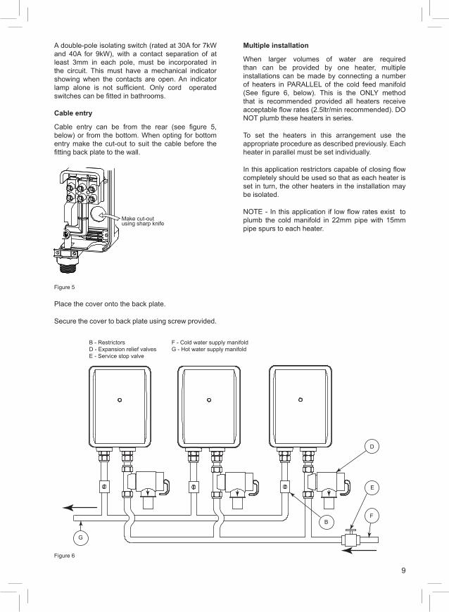
Multiple installation
When larger volumes of water are required than can be provided by one heater, multiple installations can be made by connecting a number of heaters in PARALLEL of the cold feed manifold (See figure 6, below). This is the ONLY method that is recommended provided all heaters receive acceptable flow rates (2.5ltr/min recommended). DO NOT plumb these heaters in series.
To set the heaters in this arrangement use the appropriate procedure as described previously. Each heater in parallel must be set individually.
In this application restrictors capable of closing flow completely should be used so that as each heater is set in turn, the other heaters in the installation may be isolated.
NOTE - In this application if low flow rates exist to plumb the cold manifold in 22mm pipe with 15mm pipe spurs to each heater.
A double-pole isolating switch (rated at 30A for 7kW and 40A for 9kW), with a contact separation of at least 3mm in each pole, must be incorporated in the circuit. This must have a mechanical indicator showing when the contacts are open. An indicator lamp alone is not sufficient. Only cord operated switches can be fitted in bathrooms.
Cable entry
Cable entry can be from the rear (see figure 5, below) or from the bottom. When opting for bottom entry make the cut-out to suit the cable before the fitting back plate to the wall.
Make cut-outusing sharp knife
Figure 5
Place the cover onto the back plate.
Secure the cover to back plate using screw provided.
B - Restrictors F - Cold water supply manifoldD - Expansion relief valves G - Hot water supply manifoldE - Service stop valve
B
D
E
F
G
Figure 6
10
8. Operation
8.1 General
Once installed, the heater will operate automatically when the outlet valve is opened. The valve must be opened fully to obtain the set flow/temperature. Reduced flow at the outlet will result in hotter water being delivered.
On closing the outlet valve the heating element will automatically shut down provided this tap has been fully turned off by the user.
7. Commissioning
7.1 General
After installing the product in the previous section please follow the following steps to complete the installation.
7.2 Checklist before commissioning
Check all water connections for leaks and rectify as necessary.
7.3 Commissioning procedure
Setting flow rate
To set the flow rate, make sure the water and power are turned off. Open the outlet valve fully (see figure 3, add page number) and close the flow restrictor. Open the stop valve and open the flow restrictor (allowing all air to be purged). When all air is purged switch the power on, wait for a few seconds while the water is heated and adjust the flow restrictor to give the required temperature.
Remember the outlet valve is fully opened at this point so the required temperature may need further adjustment.
It is important to note when setting the flow rate/temperature that 48°C is the point at which the average person cannot hold his or her hand under a stream of water. Under most circumstances the water temperature need not be higher than this and it is recommended that this temperature is not exceeded for normal use.
WARNING
These heaters will supply only one outlet at any time and must be controlled by a single outlet valve. DO NOT USE WITH MIXER VALVES.
11
10. Decommissioning
10.1 Decommissioning procedure
` Isolate electrical supplies and make safe ` Isolate the water supply ` Drain the product ` Remove the product ` Cap pipework
Environmental information
Products are manufactured from many recyclable materials. At the end of their useful life they should be disposed of at a Local Authority Recycling Centre in order to realise the full environmental benefits.
9. Troubleshooting
9.1 General
Your product should give trouble free operation. However if a problem occurs the table below should allow most faults to be identified. Fault finding should only be carried out by a competent person.
For any faults that cannot be identified using the fault finding chart please contact the Heatrae Sadia Service Department.
Symptom Possible cause Remedy
1. Water too hot A. Water flow too low Increase the flow by turning the stop valve
2. Water too cold A. Electrical power to the Multipoint heater is off
Ensure that the electrical supply to the Multipoint
B. Water flow too high Reduce the flow by adjusting the water control isolating valve
C. Element fault Check for open circuit
3. Temperature varies while showering, cycling hot/cold
A. Pressure switch is operating, normally making a "click" as it does so
Check water pressure/flow
B. Input pressure is below 1.0 bar (14.5psi); flow is not stable
Ensure that your stop cock and servicing valve are opened fully
4. "Power on" indicator not lit. Isolating switch "ON" but its neon not lit
A. Cartridge fuse or miniture circuit breaker (mcb) has operated in your fusebox (or consumer unit) or switch fuse
Switch off Multipoint Instantaneous and isolating switch. Renew fuse, reset the mcb. If they operate a second time, contact a qualified electrician
B. Residual current device (rcd) or (earth leakage circuit breaker) has operated
Follow the same procedure as above. If this has happened with a "split load" consumer unit on initial installation, check that the neutral core of the Multipoint Instantaneous feed cable is connected to the "protected" neutral bar of the unit
5. Water emerges from expansion relief valve
A. Expansion relief valve has operated
1. Switch off immediately at isolating switch 2. Turn water off at the servicing valve (if fitted) or stop valve 3. Contact Heatrae Sadia Service Department
6. No water flows with valve open
A. Water supply turned off Turn on water supply
B. Unit frozen Turn OFF ELECTRICITY at isolating switch and contact installer DO NOT USE THE MULTIPOINT INSTANTANEOUS
12
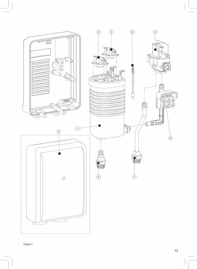
11. Spare parts
The following comprehensive list of spare parts is available for your product. Please refer to the rating label on the right hand side of your product before ordering to ensure the correct spare parts are obtained.
Do not replace with parts not recommended by Heatrae Sadia - this will invalidate your warranty and may render the installation dangerous.
Description Code No
1 Heat Exchanger 7kW 95 606 965
Heat Exchanger 9kW 95 606 966
2 Temperature limiter 1 95 612 035
3 Temperature limiter 2 95 612 036
4 Pressure differential switch assembly 7/9kW 95 613 005
5 Multipoint instantaneous cover 95 614 108
6 Neon assembly 95 615 058
7 Inlet boss assembly 95 607 106
8 Outlet boss assembly 95 607 109
9 Terminal Block 95 607 249
13
1
2 3 4
5
6
78
9
Figure 7
14
Warranty
The product warranty is for a period of two years from the date of purchase provided:
The product has been installed in accordance with these instructions, all relevant Codes of Practice and Regulations in force at the time of installation and that all necessary inlet, vent and electrical connections have been fitted correctly.
Any valves or controls are of the Heatrae Sadia recommended type.
The product has not been tampered with.
The product has been used only for heating potable water.
The product is not covered against damage by frost or due to the build-up of scale. Please note that if Heatrae Sadia personnel or agents are requested to descale a unit, this work will be chargeable.
This warranty does not affect the statutory rights of the consumer.
The policy of Heatrae Sadia is one of continuous product development and, as such, we reserve the right to change specifications without notice.

15
16
PN 36 00 6037 Issue 7
© Heatrae Sadia 2015
Please follow us online:
Electric Water Heating Co.2 Horsecroft PlacePinnaclesHarlowEssex CM19 5BTTel: 0845 055 3811E-Mail: [email protected]
SPDSpecial Product DivisionUnits 9 & 10Hexagon Business CentreSpringfield RoadHayesMiddlesex UB4 0TYTel: 020 8606 3567
Parts CenterTel: 0344 292 7057www.partscenter.co.uk
Newey & EyreUnit 3-5 Wassage WayHampton Lovett Ind. EstateDroitwich, Worcestershire WR9 0NXTel: 01905 791500Fax: 01905 791501
UK Spares LtdUnit 1155Aztec WestAlmondsburyBristol BS32 4TFTel: 01454 620500
Alternatively contact your local supplying merchant or wholesale branch or use our online stockist finder at www.interpartspares.co.uk
PRODUCT RANGEFull specification details on all our products are available to download from our website.
To support our corporate responsibility and sustainability charters and reduce our printed material we encourage you to download product brochures from our website.
In designing these files we have taken into account the need to access data on screen.
If you would like to receive a printed copy of our full product catalogue please call our literature hotline on 01603 420127.
Heatrae Sadia may introduce modifications to their products from time to time. Consequently, the details given in this brochure are subject to alteration without notice.
OUR NATIONWIDE NETWORK OF CUSTOMER SUPPORT ENGINEERSHeatrae Sadia has its very own dedicated nationwide network of highly trained customer support engineers so you can have peace of mind that we’re always here to help.
22 YEARWARRANTY
SPECIFICATION ADVICE HOTLINE
t | 01603 420220 e | [email protected]
AFTER SALES SERVICE
t | 0344 871 1535 e | [email protected]
w | heatraesadia.com