wisley 8 fitting instructions
DESCRIPTION
Hartley Botanicals Wisley 8 greenhouse fitting instructionsTRANSCRIPT

THE HARTLEY NEW WISLEY 8
ERECTION AND GLAZING INSTRUCTIONS
FROM HARTLEY BOTANIC LIMITED.
It is essential that these instructions are read carefully all the way through beforestarting erection. It is also suggested that each part is identified and how andwhen it is used to complete the structure.
The plinth on which the greenhouse is to be placed must be level and flat. Anuneven foundation will lead to frustrating delays and subsequent disappointment.
page 1
DOOR ENDASSEMBLY
RIDGE CAP
RIDGE COVERVENTILATOR ASSEMBLY
PLAIN END
SINGLE PANECROSS MEMBER
GUTTER ASSEMBLY
SPAN ASSEMBLY
LOUVRE
SIDE BASERAIL ASSEMBLY
ALUMINIUM KICK PLATE

TOOLS
1 - 8mm Drill (H.S.S or suitable for Aluminium)1 - 8mm Masonry Drill1 - Power Drill1 - Medium Screwdriver - Slotted1 - Medium Screwdriver - (Posi-Drive/Philips Head)1 - Ring Spanner1 - Open End Spanner
10mm AF Spanner for M6 Screws8mm AF Spanner for M5 Screws,1 - Tape Measure1 - Small HammerStep Ladders
SCREWS ETC...
TYPE ‘A’ Stainless steel hexagon head boltM6 x 12mm long complete with nut.
TYPE ‘B’ Stainless steel self tapping screws.(4.2mm dia x 13mm long) (8s x 1/2” long)
TYPE ‘C’ Stainless steel self tapping screws.(4.2mm dia x 9.5mm long) (8s x 3/8” long)
TYPE ‘D’ Stainless Steel self tapping screws.(4.2mm dia x 16mm long) (8s x 5/8” long)
TYPE ‘E’ Stainless steel screw.(5.5mm dia x 50mm long) (12s x 2” long)complete with scaler washer and plastic plug.
TYPE ‘G’ Stainless steel cheese head screw.M5 x 12mm long complete with nut.
TYPE ‘J’ Stainless steel hexagon head boltM6 x 16mm long complete with nut.
TYPE ‘K’ Stainless steel hexagon head boltM6 x 25mm long complete with nut.
TYPE ‘L’ Stainless steel hexagon head boltM6 x 20mm long complete with nut.
page 2

page 3
1. The two side baserail assemblies, the plain end assembly and the door endassembly should be placed on the ground to ensure that the greenhouse isorientated with the door at the correct end. (Fig 2).
2. Lay them together to form a perfect rectangle. This can be checked bymeasuring the diagonals, they must be of identical dimensions. (Fig 2).
3. Take the baserail assembly sections, place them centrally overlapping thebrickwork equally at each end. The correct distance apart for the baserailassemblies, is 2381mm. Remove the cill once the positioning has been established(Fig 3). Select a point approximately in the centre between each baserail bracket,marking out this spot for drilling. The holes are not pre drilled thus allowing theposition to be drilled precisely into a solid foundation point, and not into a joint inthe brickwork. Drill as marked (for example a 4 pane house will have 4 fixings perside) using an 8mm H.S.S drill. Drill into the foundation with an 8mm masonrydrill to a depth of 50mm to take the plug and screw provided (Fig 4). Insert theplug washer and screw, tightening only sufficiently to hold the rails into position atthis stage. Once the structure is complete, remember to tighten all fixing screwssecurely.
DOOR ENDASSEMBLY
PLAIN ENDASSEMBLY
Fig 2.
SIDE BASERAIL
CILL PLATEFig 3. Baserail drilling.Cill position.
Fig 4. Detail of new 8 house baserailand fixing
BASERAIL ASSEMBLYSEALER WASHER
PLUGCONCRETE ORSOLID BRICK BASE

4. Now the half span assemblies that create the separate pane lengths should beassembled. The prefabricated half spans are joined together at the apex with afish plate on each side (Fig 5). Place the four brackets with the short edge toeach fish plate (two on each side) and fasten with ‘L’ type bolts and nuts asshown.
5. The completed spans are now fixed between the pair of angle bracketspreviously factory fitted to the baserail assemblies. These are secured using ‘J’type bolts and nuts (Fig 6). The plain and door aend assemblies to be fixed at alater stage (Fig 14).
6. The four types of cross members are now fitted to the completed spans (Fig 7.)
‘A’ TYPENUTS
JOINING PLATE ANGLE BRACKET
‘L’ TYPE BOLTSAND NUTSFig 5. Half spans/plate screws
Fig 6. Baserail and span details
COMPLETE SPANSSPAN
BASERAIL ASSEMBLY
ANGLE BRACKETS
‘J’ TYPEBOLTS AND NUTS
page 4
Fig 7.

6a. The lowest single pane cross member at the top of the vertical span section areall of type ‘C’ (Fig 8). These members are bolted onto the brackets alreadyattached to the spans using ‘A’ type bolts and nuts.
6b. The second level of members at the top of the first facet are of two types.Where there is no vent then type ‘C’ are used as described above. Where a ventis located the cross member (type ‘D’) has a flat plate for the window openingmechanism. These are fixed in using ‘A’ type bolts and nuts (Fig 9).
6c. At the third level there are two types of members. Type ‘C’ are once again usedwhere there is no vent to be positioned and fixed as before. Where a vent is tobe positioned there is a cross member of identical form to the type ‘C’ crossmember with the exception that it has two short cuts, each 30mm from eitherend as type ‘B’ (Fig 10). This is fixed as before by placing on top of thebrackets and fastening together using ‘A’ type bolts and nuts.
6d. The final cross members are located close to the apex on either side of thegreenhouse. These are of type ‘A’ members. These are fixed as per the othermembers (Fig 11) using ‘A’ type bolts and nuts.
page 5
TYPE ‘C’ SINGLE PANECROSS MEMBER ‘A’ TYPE
BOLTS AND NUTS
TYPE ‘C’ SINGLE PANECROSS MEMBER
Fig 8.
Fig 9. Fig 10.
TYPE ‘D’ UNDERVENTCROSS MEMBER
TYPE ‘E’ OVERVENTCROSS MEMBER
Fig 11.
TYPE ‘A’ RIDGE CROSSMEMBER
TYPE ‘A’ RIDGE CROSSMEMBER
‘A’ TYPEBOLTS AND NUTS
NOTE: The opening panes can only be located at intermediatepanes i.e.: not next to an end or partition.

For guidance, the chart gives standard vent numbers and placements
7. The plain and door end assemblies are now secured to the baserail assembly,(Fig 12) using the single bracket and ‘A’ type bolts and nuts.
A typical 5 pane layout would be :-
PLAIN ENDASSEMBLY
SINGLE BRACKET
Fig 12.
page 6
SIZE
4 PANE5 PANE6 PANE7 PANE8 PANE
2.4.4.5.6.
2 OR 3 ON BOTH SIDES.2 TO 4 ON BOTH SIDES.2 TO 5 ON BOTH SIDES.2 TO 6 ON BOTH SIDES.2 TO 7 ON BOTH SIDES.
No. OF VENTS POSITION
D/END P/END &PARTITIONHORIZONTAL TO BEFITTED LOOSELYUSING M6 X 12 NUTS& BOLTS.THEN ONCE GLASS INTHESE POSITION HASBEEN FITTED BOLTSMAY THEN BETIGHTENED

8. When fixed to the baserail assembly, secure all the cross members to retain the endassemblies in position using ‘A’ type bolts and nuts. The end assemblies can now befixed into place in the same way as the baserail assemblies (Fig 13), locating two fixingsin each end assembly. The cill is now fitted to the plain end only. This is located betweenthe side baserail assemblies, pushed up hard against the end bottom rail before securing,using the 50mm plugs and screws (type ‘E’)
9. The ridge cover is now slid into position locating under the retaining lip of the type ‘A’ridge cross member. On longer structures the ridge will be in two sections. Usingsealant (not supplied) stick the joining piece over the joint. See Fig 14.
10. The first items to be glazed are the opening vent sections. The glass for theselights are 676mm x 697mm. Remove the member from the frame and slide thefully edged glass into the slot, then when in place, bolt the top member backinto position on the frame.
page 7
JOINING PIECEIF REQUIRED
‘A’ TYPCROSS B
TYPE ‘A’ RIDGE CROSSMEMBER
SPAN
RIDGE COVER
POSITIONING OF RIDGE COVER
SLIDE GLASS IN
SLIDE GLASS INAND BOLT ENDPIECE ON
Fig 14.
Fig 13.
Fig 15.
CILL
CILL
WASHER
SCREW
SECTION VIEW
RIDGE COVER PLATE

11. Now glaze the faceted section of the house starting nearest the ridge and fromone end (shall we say the door end). Each of the faceted panes are 730mm x160mm. Each P.V.C. edged pane (with the 730mm edge horizontal) is pushedup into the glazing slot in the type ‘A’ ridge cross member (Fig 16) at the angleshown, and then lowered into the slot of the cross member beneath (be it type‘B’ or ‘C’).
12. The cappings (408mm) are then fitted to the first two panes and so on as youwork along the house. The capping securing the glass to the ends is called halfcapping (Fig 17) whilst the capping to the spans is full capping. The capping issecured onto the body by ‘B’ type stainless steel self tapping screws.
Capping details and sections.Both sides are completed in the same manner.
page 8
GLASS
P.V.C. EDGING PUSH PANE UP AS SHOWN(DOTTED SECTION), AND ALLOWTO SLIDE DOWN INTO BOTTOM SLOT.
Fig 16.Glass positioning.
8s x 1/2” LONG OR4.2Ø x 13mm LONG HALF CAPPING
GLASS
GLASS
END SPAN
FULL CAPPING
Fig 17.
FULL CAPPING
HALF CAPPING
GLASS
GLASS
ST./STL. SCREW
BODY SPAN

13. The lower facet is now glazed in the same way, with the glass size 711 x 730,but this time using the 727mm long capping. Obviously with the exception ofthe space for the vent panes.
14. The next lower facet is now to be glazed and capped as previously described,once again with the glass size 711 x 730 and capping length 727mm.
15. Finally the last of the body panels to be glazed is the vertical face. This hasglass panes 730mm x 1067mm. The capping, both full and half is 1064mm long.The P.V.C. edged panes are inserted as before, they are then secured with thecapping and the ‘B’ type stainless steel screws.
16. Having glazed the body, we now come to the end assemblies. Firstly identify theglass, ready edged with P.V.C. as previously described.
The glass sections are located as before into the top glazing slot and then seatedin the lower glazing groove.
17. The capping of the plain end assembly uses two types of capping (Fig 20). Theperimeter has half capping (8 pieces) whilst the center has two pieces of fullcapping 2130mm long. These are secured as before.
page 9
Plain end glass chart.
Fig 18.
Fig 19.
TOP

page 10
18. The door end assembly glazed as shown in Fig 21. The three bolts (2, ‘A’ typeand 1, ‘K’ type and the spacer in the right hand bolt) should fit the runner. (Fig 22).
The capping used to fit the glass in position is:a. Half capping around the perimeter 8 pieces.b. Full capping (2130mm long) to the left of the door aperture and a
short piece (268mm long), located above the door aperture to theright hand side.
c. A single piece of draught seal capping (1862mm long) located to theright hand side of the door aperture.
All this capping is fixed with ‘B’ type stainless steel self tapping screws.
369mm LONGHALF CAPPING
Fig 20.
688mm LONGHALF CAPPING
1122mm LONGHALF CAPPING
1122mm LONGHALF CAPPING
688mm LONGHALF CAPPING
688mm LONGHALF CAPPING
369mm LONGHALF CAPPING
688mm LONGHALF CAPPING
1122mm LONGHALF CAPPING
1122mm LONGHALF CAPPING
Fig 21.
2130mm LONGFULL CAPPING
268mm LONGFULL CAPPING
1862mm LONGD/SEAL CAPPING
page 11
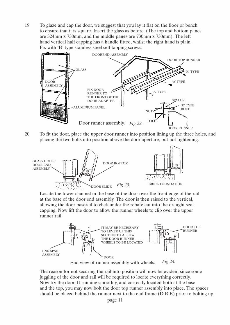
19. To glaze and cap the door, we suggest that you lay it flat on the floor or benchto ensure that it is square. Insert the glass as before. (The top and bottom panesare 324mm x 730mm, and the middle panes are 730mm x 730mm). The lefthand vertical half capping has a handle fitted, whilst the right hand is plain.Fix with ‘B’ type stainless steel self tapping screws.
20. To fit the door, place the upper door runner into position lining up the three holes, and placing the two bolts into position above the door aperture, but not tightening.
Locate the lower channel in the base of the door over the front edge of the railat the base of the door end assembly. The door is then raised to the vertical,allowing the door baserail to click under the rebate cut into the draught sealcapping. Now lift the door to allow the runner wheels to clip over the upperrunner rail.
The reason for not securing the rail into position will now be evident since somejuggling of the door and rail will be required to locate everything correctly.Now try the door. If running smoothly, and correctly located both at the baseand the top, you may now bolt the door top runner assembly into place. The spacer should be placed behind the runner next to the end frame (D.R.E) prior to bolting up.
Fig 23.
DOOR BOTTOM
DOOR SLIDEBRICK FOUNDATION
GLASS HOUSEDOOR ENDASSEMBLY
END SPANASSEMBLY
IT MAY BE NECESSARYTO LEVER UP THISSECTION TO ALLOWTHE DOOR RUNNERWHEELS TO BE LOCATED
DOOR TOPRUNNER
DOOR
Fig 24.
DOORASSEMBLY
GLASS
DOOREND ASSEMBLY
FIX DOORRUNNER TOTHE FRONT OF THEDOOR ADAPTER
ALUMINIUM PANEL
DOOR TOP RUNNER
‘K’ TYPE
‘A’ TYPE
‘A’ TYPE
Fig 22.Door runner assembly.
SPACER
NUT
D.R.E.
DOOR RUNNER
‘K’ TYPEBOLT
End view of runner assembly with wheels.

21. The complete vent can now be fitted into the greenhouse frame by hooking thevent top edge lip into the vent top cross member (type ‘B’) already fitted to thehouse. The vent is offered into the top cross member with the vent in its widestpossible open position. (Fig 25).
When finally being fixed into place the vent frame will use two pieces of greyP.V.C. strip, one down either side, to facilitate capping which is part of the finalglazing process. When the position of the vent strip is ascertained, you may findeasier to tap it into its final position with a hammer, if it is stiff. (Fig 26). In thisposition the full capping now secures not only the glass on one side but also theP.V.C. strip on the other side.
Note:- The casement stay is fitted to the lower section of the vent with a single‘A’ type bolt and nut at the completion of the erection.
22. With the ridge cover now an equal distance from either end, position the ridge end cap and mark through the holes. Drill the ridge cover with a Ø3.5 bit and secure with two type ‘B’ screws.
page 12
VENT
Fig 25.
TYPE ‘B’CROSS MEMBER
Vent being positioned.
RIDGE COVER
RIDGE CAP
GLASS HOUSE ENDASSEMBLY
Fig 27.
VENT
P.V.C. STRIP
FULL CAPPING
GLASS
BODY SPAN
Fig 26.

page 13
Fig 28.
FLAT CLIP
CIRCULAR CLIP
GUTTER AND DOWNPIPE
23. On structures longer than 7 panes in length, the gutter will be in two parts, with awelded slip joint. Slide the two halves together and drill a Ø7mm hole through thecentre. Slide the two halves apart and apply a liberal amount of sealant (not supplied)to the slip joint. Slide the two halves back together and secure with a type ‘A’ screw andnut. Centralize the gutters so that the same amount protrudes at each end. See Fig.28.
Remove the capping screws from just below the eaves at the top of the span verticals.
Place the long gutter section in position as shown in Fig 29 ensuring contact upagainst the cross member at eaves (‘C’).
Each of the flat clips to be placed underneath the gutter, holding it firmly with‘D’ type screws, using the holes in the span vertical capping.Take the plastic spigot ‘U’ and collar ‘V’ and un-couple by screwing anti-clockwise.Position the spigot in the top of the gutter outlet hole and slide the collar over thetop of the downpipe. Push the downpipe up onto the spigot and slide the collarupwards as far as it will go. Screw the collar clockwise until the downpipe is secured. Slide the downpipe bracket until it aligns with a capping hole. Using a self tappingscrew ‘D’ fix the bracket into position through the capping. See Fig 30.
The glasshouse main structure is now completed.
Fig 29.Fig 30.
GUTTER
GUTTER
DOWNPIPE
DOWNPIPE
TYPE ‘C’ CROSSMEMBER
‘D’ TYPESELF TAPPINGSCREWS
FLAT CLIP
‘D’ TYPESELF TAPPINGSCREWS
CIRCULAR CLIP
SPANVERTICALCAPPING
U
V

STAGING – MK1 TYPE
Identify the left and right end brackets and place against inside the gable frame using thedimension shown in Fig. 31. Mark through the two holes, spot and drill using a 6.5mm bit. Note:be careful to drill only the inner face of the gable frame. Secure with type ‘b’ screws with the nutbehind. Attach the intermediate brackets to the spans with type ‘h’ self tapping screws, usingthe dimensions shown in Fig. 32. Note: the bracket positions given place the legs at the plinth toplevel. If the floor is lower, then the brackets should be lowered by the same amount.
The corner sections of the staging framework may be supplied in straight lengths with twonotches some distance from either end, simply and gently bend these by hand to form a 90˚angle as shown in Fig 33.
Make up the complete box sections with the intermediate straight sections, the cross membersand the staging legs, bolting all these together with ‘b’ type bolts and nuts.
The entire assembly can now be placed in position, the back edge sitting on the brackets andthe front standing on its legs.Place the corrugated trays in position with trays overlapping each other at the ends.
NOTE: To help retain moisture and to provide a flat surface, we suggest that pea gravel bespread over the surface of the boards to a depth of at least 1”.
page 14
Fig 31.Fig 32.
Fig 33.
END BRACKET ONE LEFT HANDONE RIGHT HAND BOLTED TO ENDSUSING ‘B’ BOLTS
BRACKET SCREWEDTO ALL HALF SPANS4.2mm SCREWS (SELF TAPPING)9.5mm LONG (TYPE ‘H’)
END BRACKETS
769m
mF
RO
M P
LIN
TH
TO
TO
P O
F B
RA
CK
ET
INTERMEDIATE SECTION
CORNER SECTION
STAGING LEGS
CORNERSECTION CORNER
SECTION
STAGING LEGS
INTERMEDIATE SECTION
CROSS MEMBER
CROSS MEMBER
CROSSMEMBERS

SHELVING ERECTION INSTRUCTIONS
When erecting the shelving, support brackets should be screwed to the spans at the dimensions shown in the sketch, using ‘C’ type self tapping screws. Hook the support into the pair of brackets consistently on either the left ot the right hand side of the brackets. There are two types of shelving laths, one with a plain end and one with a slot at both ends.
Position and fix the horizontal support bracket to the gable vertical pre drilled hole using type ‘A’ bolt. Clamp the bracket at the other end and drill through with a 06.5mm bit. Fix using type ‘A’ bolt and repeat at the other gable.
Starting from the gable end, take the end laths and place four sections with the unslotted ends resting on the gable horizontal glazing member. Place the slotted ends on the shelvng sling. Take four middle laths and position alternately between the end laths on the support sling. Continue along the glasshouse until the final four end laths are fitted. Note; take great care not to disturb the slings until the final laths are positioned. See Fig. 34.
Note: If the shelving does not run the full length between the ends or end and partition (such as ashort run or the position in front of a partition), drill and bolt one end lath using the 35mm long screw provided.
LOUVRE
There are two sizes of louvre frames, one of these can replace any bottom pane of glass, the other can be placed in the centre of the plain end, by simply replacing glass pane ‘D’. When being used in the side replacing pane (c) the louvre will go in between the panes, resting in the slot in the baserail. A splitter section (Fig 35) is then placed on top of the louvre and pressed down firmly.
The small piece of glass (k) or (m) is pushed up into the cross brace, then lowered into the groove above the louvre to make up the complete pane. A piece of capping can then be fastened down either side, holding both the glass and louvre in position (Fig 36.)
page 15
Fig 34.
SUPPORT BRACKET GLASSHOUSEEND SPAN
HORIZONTALSUPPORT BRACKET
THIS END TO RESTON THE HORIZONTALANGLE SUPPORT
SHELVING LATHS
SHELVING LATHS
SHELVING SUPPORTSLING
THIS END TO SLOT INTONEXT SUPPORT
‘C’ TYPESELF TAPPING SCREWS
BRACKET
120mm
85m
m
Fig 35.
SPLITTER SECTIONEND SPLITTER 736mm LONGSIDE SPLITTER 714mm LONG
GLASS PANEOVER LOUVREBODY 730 x 435END 85 x 752
LOUVRE

BLINDS
Instructions for fixing sprung roller blinds:
It is important to note that the blinds have a flat spindle at one end which shouldalways be offered up to the ridge with the flat spindle on the left (end blinds are27mm shorter than the middle ones).Brackets to hold blinds and rollers to be positioned and fixed into the span slot withself tapping screws at the dimension shown using ‘C’ type screws.
Ends Only:Fix the flat bracket to the gable end member by drilling two holes using a bracket as atemplate. Fasten with self tapping screws.
Brackets to be in line along glasshouse.
Fix the cord wheel assembly centrally using ‘A’ type screws, to inside edge of the type‘C’ cross member - alternatively, if staging is present, fix the lower edge of the stagingallowing cord to pass underneath as shown, to be held at the front by the cleat.
page 16
FOUR BRACKETS
FLAT BRACKETROUND HOLE A
FLAT BRACKETSLOTTED B
BENT BRACKETROUND HOLE C
CORD CLEAT
BENT BRACKETSLOTTED D
SPAN SLOTEND SPAN
MIDDLE SPAN
SELF TAPPINGSCREW
END BLIND709mm
INNER BLIND736mm LONG
CORD CLEAT
WHEEL ASSEMBLY
VIEW LOOKING TOWARDS RIDGE (OUTSIDE TO IN)
50mm
57m
m
265m
m
50m
m

AUTOVENT
Fitting an autovent:
1. Remove existing casement stay from vent2. Fix Bayliss autovent to bracket with the screw supplied. (‘A’ and ‘G’ type).3. Using the existing hole in the cross member, fix the bracket with a nut and bolt.4. Using the holes in the Bayliss as a template, drill two holes with a No. 7 drill.5. Fix with screws and nuts as shown.6. Refer to Bayliss instructions for setting.
(if used with shelving autovents can be connected in reverse).
page 17
Autovent ArmsThumb Screw
Appendix
AUTOVENT
Changes made to Autovent adverse weather conditions ie.: strong winds or storms
1) Remove thumb screw from the Autovent
2) Place string around the Autovent arms and tie shut
This will enable the Autovent to stay in the closed position until the weather conditionschange where the Autovent can be restored to its normal working position

Swing Door
For �glass-to-ground� type structures, take the door assembly and position into the door gable aperture. Note: inward opening doors fit from the inside, but outward opening doors fit from the outside. With one person holding the outer frame, open the door and with a 7mm bit, drill straight through the door outer frame and the structure frame in the eight approximate positions shown in Fig.1. Note: avoid hinge and lock positions. Secure the frame with M6x30 screws � pushed in from the door side.
Tip: drill and bolt the top holes first to relieve the assistant.
When fitting the door to a �planthouse� (version with a dwarf wall), the door is fitted as above, but with 12s x 100mm long screws in the lower four positions. Drill the holes with a 7mm bit and mark the four positions through onto the wall. Remove the door frame and open up the holes in the gable verticals so that they will clear the plastic rawl plugs. Drill the walls with an 8mm masonry bit and insert the rawl plugs. Replace the door and secure with the 12s x 100mm long screws. See Fig.2.
Fig. 1
Fig. 2page 18

With the adjacent gable panes in position, take a door capping spacer and position it against the non-glazed side of a gable door-vertical. Secure the vertical full capping using No.8x12 self tapping screws. Repeat at the other side. Take the 737mm long half capping and with the leg on the non-glazed side, screw to the horizontal above the door (for outward opening doors this will be full capping). See Fig.3.
Place the 1033x545 pane in the top of the door and the 593x545 kick panel in the bottom of the door. With the assistant supporting them, position the door vertical half capping and secure with No.8x9.5 self tapping screws. Position the upper and lower half capping, then the horizontal full capping and secure with No.8x9.5 screws. See Fig.4.
Fig. 3
Fig. 4
page 19

page 20
Mk2 DOMESTIC STAGING Section 1. Attached staging for the sides of glass-to-ground structures Identify the left and right end brackets and place against inside of the gable frame using the dimension shown in Fig.1. Mark through the two holes, spot and drill using a 6.5mm bit. Note; be careful to drill only the inner face of the gable frame. Secure with M6x12 button head screws with the nut behind.
Tip: when drilling, use a small pilot drill first and get someone to hold a scrap sheet of metal or plastic behind to hole to prevent damage when the drill runs through. Take the mid brackets and using the fixing position shown in Fig.1, secure to the screw slots on the inside of the spans using 9.5mm long self tapping screws. Note: if the floor of the greenhouse is set lower than the plinth top, the dimensions to the top of the end and mid brackets must be increased by the difference.
Fig. 1

page 21
Fig. 2
Take two front/rear end frames (one of each hand) and an end frame. Place the corners together and push a corner piece into the recess on the outside of the frame so that the holes align. Position M6 nuts into the recess behind the holes and secure with M6x12 button head screws. Repeat for the other end frame.
Take a front/rear mid frame and position end-to-end with the assembled end frame. Slide a butt strap into the recess on the outside of the frame so that the holes align and secure with M6x12 button head screws. On the other side use a mid leg (which is a T-section) to join the mid frame, again using M6x12 button head screws. Continue along until all the sections are joined and the mid legs are in place. See Fig.2. Note for staging with lath top tray; on structures with a length of six panes or more, the three holes in the front/rear mid frames must be central to the entire run. Use the chart below in order to achieve this. 6 PANE � END FRAME � 743mm MID FRAME � 1486mm MID FRAME � 743mm MID FRAME � END FRAME
7 PANE � END FRAME � 743mm MID FRAME � 2229mm MID FRAME � 743mm MID FRAME � END FRAME
8 PANE � END FRAME � 1486mm MID FRAME � 1486mm MID FRAME � 1486mm MID FRAME � END FRAME
9 PANE � END FRAME � 1486mm MID FRAME � 2229mm MID FRAME � 1486mm MID FRAME � END FRAME
10 PANE � END FRAME � 2229mm MID FRAME � 1486mm MID FRAME � 2229mm MID FRAME � END FRAME
Lift the staging assembly (with help from others if needed) onto the end and mid brackets which were fitted earlier. Using a spirit level and string, ensure that the staging is even and level by making adjustments to the ground under the legs if necessary. See Fig.3. For the fitting of the top tray, please refer to section 3.
Fig. 3

page 22
Fig. 4
Fig. 5
Section 2. Stand alone staging for gables and planthouse (walled) structures.
Take two front/rear end frames (one of each hand) and an end frame. Place the corners together and push a corner leg (angle section) into the recess on the outside of the frame so that the holes align. Position M6 nuts into the recess behind the holes and secure with M6x12 button head screws. Repeat for the other end frame.
Take a front/rear mid frame and position end-to-end with the assembled end frame. Slide a mid leg (T-section) into the recess on the outside of the frame so that the holes align and secure with M6x12 button head screws. Repeat on the other side and continue along until all the sections are joined and the mid legs are in place. See Fig.4. Position a shelf support against the holes in the corner legs, ensuring that the side with lath holes is lowermost. Secure with M6x12 button head screws. Repeat at the other end. Position the remaining shelf supports against the holes in the mid legs and, ensuring that the sides with the lath holes are uppermost, secure with M6x12 button head screws. See Fig.5.

page 23
Fig. 6
Fig. 7
Take a shelving lath and slide M6x12 hexagon head screws into the screw slot � one for each shelf support. Slide the screws along so that they align with the holes in the support angles. Lower the lath onto the support angles and locate the screws through the shelving support holes. Secure from underneath with an M6 nut and continue along until all the laths are in place. See Fig.6 and Fig.7.
Note: for staging lengths of up to 5 panes, the shelving lath will be supplied in a single length, but for structures of six panes or more, the shelf lath will be supplied in two or more lengths. For structures of six panes length or more, establish where the laths join using the chart below. At each of these positions fit a second shelf support on the opposite side of the mid leg. If placed in the correct order, the shelf laths will join at the midpoint between the two back to back supports.
For the fitting of the top tray, please refer to section 3.

page 24
Section 3. Top tray. Lath Type The front/rear mid frame of the top tray should have three holes at the central position of the staging. To enable the alignment of the last lath with the slot near the end of the front/rear end frame, the middle lath must be positioned over either the centre hole or the off-centre holes, dependent upon the staging length. See the chart below: POSITION OF MID LATH LENGTH PLANTHOUSE (WALLED) STRUCTURE GLASS-TO-GROUND STRUCTURE 3 PANE OFF-CENTRE HOLE CENTRE HOLE 4 PANE CETNRE HOLE OFF-CENTRE HOLE 5 PANE CETNRE HOLE OFF-CENTRE HOLE 6 PANE OFF-CENTRE HOLE CENTRE HOLE 7 PANE CETNRE HOLE OFF-CENTRE HOLE 8 PANE CENTRE HOLE OFF-CENTRE HOLE 9 PANE OFF-CENTRE HOLE CENTRE HOLE 10 PANE OFF-CENTRE HOLE CENTRE HOLE
Take a middle/end lath (these have a screw slot underneath as opposed the intermediate laths which do not). Slide an M6x12 hexagon head screw a little way in each end and drop the lath into the frame with the screws locating into the central holes. Secure the lath from underneath with M6 nuts. See Fig.8. Take two plastic spacing blocks and push them onto the inside of the front/rear frame until they click into place (ensure they are pushed tightly against the lath). Drop in an intermediate lath (with no screw slot) and push tightly against the spacing blocks. Continue along either side of the centre lath until the last position is reached. Take two middle/end laths and slide an M6x12 hexagon head screw a little way in each end. Drop into the staging frame, locating the screws in the end position slots. Slide the laths tightly against the spacing blocks and secure from underneath with M6 nuts. See Fig.9.
Fig. 9
Fig.8

page 25
Flat or Corrugated Sheet type For flat and corrugated sheet options cross members will be necessary for additional support. For flat sheet trays the sheets must adjoin on the centre of the cross member. Position sheets in the trays and align the cross members under the joints. Mark through the brackets at either end. Remove the sheets and cross members and drill through the front/rear frames using a 7mm bit. Re-position the cross members and secure with M6x16 button head screws. For corrugated sheets, position the cross members at approximately equal distances apart. See Fig. 10. Note: lengths up to 4 pane have 1 cross member, lengths up to 7 pane have 2 cross members and lengths up to 10 panes have 5 cross members. Drop the flat sheet or corrugated sheets into position. The corrugated sheets are supplied over-length and should be overlapped until the required size is obtained. See Fig. 11 and Fig. 12.
Fig. 10
Fig. 11 Fig. 12

Section 4. Potting Shoe For staging with a lath type top tray, place the shoe in the desired location on top of the laths and mark through the four holes in the base. Remove the shoe and drill the four positions with a Ø3.5mm bit. Replace the shoe and secure with No.8x9.5 self tapping countersunk screws. For staging with a flat sheet top tray, place the shoe on top of the flat sheet. Securing with the self tapping screws is optional. For staging with a corrugated sheet type top tray, place the shoe at the desired end of the staging and lap the corrugations as close to the shoe as possible. Section 4. Partitions Stand-alone planthouse (walled structure) staging remains unaffected, but attached staging on a glass-to-ground structure needs to be shorter at the front glazed side of the partition. This is achieved by use of a shorter 593mm front/rear end frame. Ensure that these are used at the partition end of the staging. Because the short section has no radial/span to which it can be attached, an extra leg is supplied for use at the rear corner. Section 5. Abutting Structures Glass-to-ground attached staging remains unaffected, but planthouse (walled structure) staging is increased in length to fill the gap created by the lack of a wall at the abutting end. This is achieved by use of a longer 743mm front/rear end frame. Ensure that these are used at the abutting end. In order that the lengths of the shelving laths remain consistent, the end tray at the abutting uses corner pieces and mid legs set in from the end (as outlined in section 1). Section 6. Gable Staging Staging across the gable is always of the free-standing type, with a lower parcel shelf. The staging will fit on one of three ways; across a full gable, next to one side of staging to create an L shape, and between two sides of staging. The assembly method is the same as that shown in section 2, with the only difference being that the front/rear frame is in one piece.
page 26

page 27
!"#$%$%&'(
!"##$%&'()'*+,-&.'/'0'1+%2%3"4'56'
72&'8$3#+#+"9'$,,&:;-.'+,':<=2'#2&',$:&'$,'#2&'>""3'%$;-&'$,,&:;-.';<#'=$3&':<,#';&':$>&'9"#'#"'="9?<,&'#2&'#4"'+#&:,@''72&'8$3#+#+"9'=$9';&'+>&9#+?+&>';.'#2&'&A#3$';3$=B&#,'42+=2'$3&'-"=$#&>'"9'#2&'?3"9#)'$,'4&--'$,'#2&'3&$3@'''C&&'D+%@5@'
E",+#+"9'#2&'8$3#+#+"9'$,,&:;-.'+9#"'#2&';$,&3$+-';3$=B&#,)'4+#2'#2&'%-$F+9%',+>&'G$-,"'#2&',+>&'"9#"'42+=2'#"'>""3'4+--'$##$=2H'?$=+9%'#2&'>""3'&9>@''C&=<3&'#2&'$,,&:;-.'4+#2'#2&',$:&',=3&4,'<,&>'?"3'#2&'$##$=2:&9#'"?'#2&',8$9,@'
'
'
I##$=2'#2&'=3",,:&:;&3,'#"'#2&';3$=B&#,'"9'&+#2&3',+>&'"?'#2&'8$3#+#+"9'+9'#2&',$:&'4$.'$,'#2&.'$3&'$##$=2&>'#"'#2&',8$9,@''J"#&'K'+?'$'L&9#'+,'9&A#'#"'#2&'8$3#+#+"9)'#2&9'#2&'<9>&3'L&9#'G:$9<$-'"9-.H'=3",,:&:;&3'8",+#+"9&>'$#'#2&'3&$3'"?'#2&'$,,&:;-.'2$,'$',8&=+$-'9"#=2@''72&'=3",,:&:;&3'8",+#+"9&>'$#'#2&'?3"9#'+,'
,#$9>$3>@''C&&'D+%@M@'
N-$F+9%'$9>'?+##+9%'"?'>""3'+,'#2&',$:&'$,'"9'#2&'>""3'&9>)'2"4&L&3'"9',":&':">&-,'"9-.'9$33"4'>"<;-&'>""3,'=$9';&'<,&>@''C&&',&8$3$#&',2&&#'?"3'?+##+9%'"?'>"<;-&'>""3,@'
)%*+,(
)%*+-(

!"#$%&'!""('
!"##$%&'()'*+,-$.'/'$01'2+%3%4"5'67'
83&'1"9:-&'1""4'$,,&;:-.'<"4'9,&'"0'&+#3&4'%$:-&'&01,'"4'=$4#+#+"0,'5+--'<+#'+0';9>3'#3&',$;&'5$.'$,'$',#$01$41',+0%-&'1""4'$,,&;:-.?''2"5&@&4)'#3&4&'$4&'$'<&5'1+<<&4&0>&,'"<'53+>3'#3&'+0,#$--&4',3"9-1':&'$5$4&?'
*3&0'%-$A+0%'#3&'1"9:-&'1""4'%$:-&'"4'=$4#+#+"0'$,,&;:-.)'BC,&$-'>$==+0%'+,'9,&1'"0'&+#3&4',+1&'"<'#3&'1""4'$=&4#94&?''D',3"4#'<9--'>$==+0%'+,'9,&1'$:"@&'&$>3?''E&&'F+%?6?'
G-$A&'#3&'1""4,'+0'#3&',$;&'5$.'$,'1&,>4+:&1'+0'#3&',+0%-&'1""4',&>#+"0)':9#'0"#&'#3$#'#3&'3$-<'>$==+0%'5+#3'#3&'3$01-&'+,'=",+#+"0&1'#"'#3&'4+%3#'"<'#3&'-&<#'1""4'$01'#"'#3&'-&<#'"<'#3&'4+%3#'1""4?''83&'-&<#'3$01'1""4'>$0':&'+1&0#+<+&1':.'$'14$9%3#',&$-'=4"#491+0%'<4";'#3&'4+%3#'4+1&)'$,'@+&5&1'<4";'#3&'<4"0#?'E&&'F+%?H?'
I&<"4&'$##$>3+0%'#3&'1""4'4900&4)'-">$#&'#3&'1""4'53&&-,'+0#"'#3&'#4$>J'$#'&+#3&4'&01'"<'#3&'4900&4'$01',-+1&'#3&'1""4,'+0#"'#3&';+11-&?''K+<#'#3&'1""4'$,,&;:-.'"0#"'#3&'1""4',-+1&',"'#3$#'#3&'%9+1&'$#'#3&':"##";'"<'#3&'1""4,'$-+%0,'5+#3'#3&'9=,#$01'"<'#3&'1""4',-+1&?''E&>94&'#3&'1""4'4900&4'5+#3'L(M6H',>4&5,?'''
'
Fig. 1
Fig. 2
&%$#!" '!"
*)(&%$#!"#
&-:9"1&83&'-%$:&43#&+
'
' ' ' ' ' '
' ' ' ' ' ' '' ' ' ' ' ' '' ' ' ' ' ' ' '' '' ' ' ' ' '
' ' ' '' '
' ' ' ' ' ' '' ' '
' ' ' ' ' ''' ' ' ' ' ''
' ' ' ' ' ' ' '' ' ' ' '
' ' ' ' ' ' '' ' ' ' ' ' ' ' '' ' ' ' ' '' '
' ' ' ' '' ' ' ' ' '
' ' ' ' '
' ' ' ' ' ' ' ' ' ' ' ' ' ' '' ' ' ' '' ' ' ' ' ' ' ' ' ' ' ' ' ' '
' ' ' ' ' ' ' ' ' '' ' ' ''''
'
("'!"
76"543%%+201'$/.$-,+*
0"&,94"<.-:;&,$,4""10+#+<--+5,0"+#+#$4=4",1&0&'
'
' ' ' ' ' '
' ' ' ' ' ' '' ' ' ' ' ' '' ' ' ' ' ' ' '' '' ' ' ' ' '
' ' ' '' '
' ' ' ' ' ' '' ' '
' ' ' ' ' ''' ' ' ' ' ''
' ' ' ' ' ' ' '' ' ' ' '
' ' ' ' ' ' '' ' ' ' ' ' ' ' '' ' ' ' ' '' '
' ' ' ' '' ' ' ' ' '
' ' ' ' '
' ' ' ' ' ' ' ' ' ' ' ' ' ' '' ' ' ' '' ' ' ' ' ' ' ' ' ' ' ' ' ' '
' ' ' ' ' ' ' ' ' '' ' ' ''''
'
0
'
' ' ' ' ' '
' ' ' ' ' ' '' ' ' ' ' ' '' ' ' ' ' ' ' '' '' ' ' ' ' '
' ' ' '' '
' ' ' ' ' ' '' ' '
' ' ' ' ' ''' ' ' ' ' ''
' ' ' ' ' ' ' '' ' ' ' '
' ' ' ' ' ' '' ' ' ' ' ' ' ' '' ' ' ' ' '' '
' ' ' ' '' ' ' ' ' '
' ' ' ' '
' ' ' ' ' ' ' ' ' ' ' ' ' ' '' ' ' ' '' ' ' ' ' ' ' ' ' ' ' ' ' ' '
' ' ' ' ' ' ' ' ' '' ' ' ''''
'
'
' ' ' ' ' '
' ' ' ' ' ' '' ' ' ' ' ' '' ' ' ' ' ' ' '' '' ' ' ' ' '
' ' ' '' '
' ' ' ' ' ' '' ' '
' ' ' ' ' ''' ' ' ' ' ''
' ' ' ' ' ' ' '' ' ' ' '
' ' ' ' ' ' '' ' ' ' ' ' ' ' '' ' ' ' ' '' '
' ' ' ' '' ' ' ' ' '
' ' ' ' '
' ' ' ' ' ' ' ' ' ' ' ' ' ' '' ' ' ' '' ' ' ' ' ' ' ' ' ' ' ' ' ' '
' ' ' ' ' ' ' ' ' '' ' ' ''''
'
%$:$,&3#3>;9
;&,,$1""4,&0>&4&<<1+
5$:& &?$4
0+A$-%0&*3"0+#+#4=$ ,'$
1&+,43&#+&"0'>$--9<#4",3
6??%F+
'
' ' ' ' ' '
' ' ' ' ' ' '' ' ' ' ' ' '' ' ' ' ' ' ' '' '' ' ' ' ' '
' ' ' '' '
' ' ' ' ' ' '' ' '
' ' ' ' ' ''' ' ' ' ' ''
' ' ' ' ' ' ' '' ' ' ' '
' ' ' ' ' ' '' ' ' ' ' ' ' ' '' ' ' ' ' '' '
' ' ' ' '' ' ' ' ' '
' ' ' ' '
' ' ' ' ' ' ' ' ' ' ' ' ' ' '' ' ' ' '' ' ' ' ' ' ' ' ' ' ' ' ' ' '
' ' ' ' ' ' ' ' ' '' ' ' ''''
'
=-%0+,14$10$#,$,$.$5;&$<$&4$&43&#)4&@&"52?.:-
3"9-,4&--$#0,+3'>3+5"<
4"&-:$%4""1&-:9"1&3#%0)'B-.:;&, C ,&9,'+%0+==>$-$,&
D'?&94#4=&$1""43&#"<1&&@":$1,&9,'+%0+==>$ 3>$'& E?'
'
' ' ' ' ' '
' ' ' ' ' ' '' ' ' ' ' ' '' ' ' ' ' ' ' '' '' ' ' ' ' '
' ' ' '' '
' ' ' ' ' ' '' ' '
' ' ' ' ' ''' ' ' ' ' ''
' ' ' ' ' ' ' '' ' ' ' '
' ' ' ' ' ' '' ' ' ' ' ' ' ' '' ' ' ' ' '' '
' ' ' ' '' ' ' ' ' '
' ' ' ' '
' ' ' ' ' ' ' ' ' ' ' ' ' ' '' ' ' ' '' ' ' ' ' ' ' ' ' ' ' ' ' ' '
' ' ' ' ' ' ' ' ' '' ' ' ''''
'
&5&
1'
1,&
&&E
'
' ' ' ' ' '
' ' ' ' ' ' '' ' ' ' ' ' '' ' ' ' ' ' ' '' '' ' ' ' ' '
' ' ' '' '
' ' ' ' ' ' '' ' '
' ' ' ' ' ''' ' ' ' ' ''
' ' ' ' ' ' ' '' ' ' ' '
' ' ' ' ' ' '' ' ' ' ' ' ' ' '' ' ' ' ' '' '
' ' ' ' '' ' ' ' ' '
' ' ' ' '
' ' ' ' ' ' ' ' ' ' ' ' ' ' '' ' ' ' '' ' ' ' ' ' ' ' ' ' ' ' ' ' '
' ' ' ' ' ' ' ' ' '' ' ' ''''
'
'
' ' ' ' ' '
' ' ' ' ' ' '' ' ' ' ' ' '' ' ' ' ' ' ' '' '' ' ' ' ' '
' ' ' '' '
' ' ' ' ' ' '' ' '
' ' ' ' ' ''' ' ' ' ' ''
' ' ' ' ' ' ' '' ' ' ' '
' ' ' ' ' ' '' ' ' ' ' ' ' ' '' ' ' ' ' '' '
' ' ' ' '' ' ' ' ' '
' ' ' ' '
' ' ' ' ' ' ' ' ' ' ' ' ' ' '' ' ' ' '' ' ' ' ' ' ' ' ' ' ' ' ' ' '
' ' ' ' ' ' ' ' ' '' ' ' ''''
'
"1&3#&A$G-0'+1':&+4>,1&
0 3&##3$#&"#1&0+"+#,"=+,&<-&'3#"#1$0>1""401'3$194#"4=-$,&;"4<1&5&@+
##$&"4<I& $>"1&3#&1+,-
'
' ' ' ' ' '
' ' ' ' ' ' '' ' ' ' ' ' '' ' ' ' ' ' ' '' '' ' ' ' ' '
' ' ' '' '
' ' ' ' ' ' '' ' '
' ' ' ' ' ''' ' ' ' ' ''
' ' ' ' ' ' ' '' ' ' ' '
' ' ' ' ' ' '' ' ' ' ' ' ' ' '' ' ' ' ' '' '
' ' ' ' '' ' ' ' ' '
' ' ' ' '
' ' ' ' ' ' ' ' ' ' ' ' ' ' '' ' ' ' '' ' ' ' ' ' ' ' ' ' ' ' ' ' '
' ' ' ' ' ' ' ' ' '' ' ' ''''
'
,$.$5&;$,&3#0+,4"":9#"0)+#>&,1""4&-0%+,3�'01-3$3'#+50%==+$><-3$3&4""1#<<-&&3#<"#3+%4&3#"#1#&<<-&'83?4""1#3%+4&'3#<"#&<<3#9%$14$:.1'&+<+0#1&+:&0'$>
,'$)&1+4#3%+4&3#;"4<%0+1?#0"4<&3#; H??%F+E&&'
&'$#>"-)&400944""1&'3#%0+3$>1&3##<<#+K&-11+;&3#"#0+,'4"
'
' ' ' ' ' '
' ' ' ' ' ' '' ' ' ' ' ' '' ' ' ' ' ' ' '' '' ' ' ' ' '
' ' ' '' '
' ' ' ' ' ' '' ' '
' ' ' ' ' ''' ' ' ' ' ''
' ' ' ' ' ' ' '' ' ' ' '
' ' ' ' ' ' '' ' ' ' ' ' ' ' '' ' ' ' ' '' '
' ' ' ' '' ' ' ' ' '
' ' ' ' '
' ' ' ' ' ' ' ' ' ' ' ' ' ' '' ' ' ' '' ' ' ' ' ' ' ' ' ' ' ' ' ' '
' ' ' ' ' ' ' ' ' '' ' ' ''''
'
&01-
#3#
$>4#&'3#"#0+,&&-354""1&'3#&'4""1&3#"#0".-:;,,&$4""1
'
' ' ' ' ' '
' ' ' ' ' ' '' ' ' ' ' ' '' ' ' ' ' ' ' '' '' ' ' ' ' '
' ' ' '' '
' ' ' ' ' ' '' ' '
' ' ' ' ' ''' ' ' ' ' ''
' ' ' ' ' ' ' '' ' ' ' '
' ' ' ' ' ' '' ' ' ' ' ' ' ' '' ' ' ' ' '' '
' ' ' ' '' ' ' ' ' '
' ' ' ' '
' ' ' ' ' ' ' ' ' ' ' ' ' ' '' ' ' ' '' ' ' ' ' ' ' ' ' ' ' ' ' ' '
' ' ' ' ' ' ' ' ' '' ' ' ''''
'
1&0&43#&+$#J$> 900&43&#"<&3##$&1+9%&3##$3#,"&1+,-4
'
' ' ' ' ' '
' ' ' ' ' ' '' ' ' ' ' ' '' ' ' ' ' ' ' '' '' ' ' ' ' '
' ' ' '' '
' ' ' ' ' ' '' ' '
' ' ' ' ' ''' ' ' ' ' ''
' ' ' ' ' ' ' '' ' ' ' '
' ' ' ' ' ' '' ' ' ' ' ' ' ' '' ' ' ' ' '' '
' ' ' ' '' ' ' ' ' '
' ' ' ' '
' ' ' ' ' ' ' ' ' ' ' ' ' ' '' ' ' ' '' ' ' ' ' ' ' ' ' ' ' ' ' ' '
' ' ' ' ' ' ' ' ' '' ' ' ''''
'
4900& 1$0&
'
' ' ' ' ' '
' ' ' ' ' ' '' ' ' ' ' ' '' ' ' ' ' ' ' '' '' ' ' ' ' '
' ' ' '' '
' ' ' ' ' ' '' ' '
' ' ' ' ' ''' ' ' ' ' ''
' ' ' ' ' ' ' '' ' ' ' '
' ' ' ' ' ' '' ' ' ' ' ' ' ' '' ' ' ' ' '' '
' ' ' ' '' ' ' ' ' '
' ' ' ' '
' ' ' ' ' ' ' ' ' ' ' ' ' ' '' ' ' ' '' ' ' ' ' ' ' ' ' ' ' ' ' ' '
' ' ' ' ' ' ' ' ' '' ' ' ''''
'
"1&3#&1+,-3&#"<";#:"#
,?5&,>4
'
' ' ' ' ' '
' ' ' ' ' ' '' ' ' ' ' ' '' ' ' ' ' ' ' '' '' ' ' ' ' '
' ' ' '' '
' ' ' ' ' ' '' ' '
' ' ' ' ' ''' ' ' ' ' ''
' ' ' ' ' ' ' '' ' ' ' '
' ' ' ' ' ' '' ' ' ' ' ' ' ' '' ' ' ' ' '' '
' ' ' ' '' ' ' ' ' '
' ' ' ' '
' ' ' ' ' ' ' ' ' ' ' ' ' ' '' ' ' ' '' ' ' ' ' ' ' ' ' ' ' ' ' ' '
' ' ' ' ' ' ' ' ' '' ' ' ''''
'
1&3##<<#+K?&-11+;&3#"#0+,'4"#9=,3'#+50,%+-$,1""43&
'
' ' ' ' ' '
' ' ' ' ' ' '' ' ' ' ' ' '' ' ' ' ' ' ' '' '' ' ' ' ' '
' ' ' '' '
' ' ' ' ' ' '' ' '
' ' ' ' ' ''' ' ' ' ' ''
' ' ' ' ' ' ' '' ' ' ' '
' ' ' ' ' ' '' ' ' ' ' ' ' ' '' ' ' ' ' '' '
' ' ' ' '' ' ' ' ' '
' ' ' ' '
' ' ' ' ' ' ' ' ' ' ' ' ' ' '' ' ' ' '' ' ' ' ' ' ' ' ' ' ' ' ' ' '
' ' ' ' ' ' ' ' ' '' ' ' ''''
'
4""1&3#"#0".-:;,,&$4""11+-,1""43&#"<01'$# &'49E&>&?
'
' ' ' ' ' '
' ' ' ' ' ' '' ' ' ' ' ' '' ' ' ' ' ' ' '' '' ' ' ' ' '
' ' ' '' '
' ' ' ' ' ' '' ' '
' ' ' ' ' ''' ' ' ' ' ''
' ' ' ' ' ' ' '' ' ' ' '
' ' ' ' ' ' '' ' ' ' ' ' ' ' '' ' ' ' ' '' '
' ' ' ' '' ' ' ' ' '
' ' ' ' '
' ' ' ' ' ' ' ' ' ' ' ' ' ' '' ' ' ' '' ' ' ' ' ' ' ' ' ' ' ' ' ' '
' ' ' ' ' ' ' ' ' '' ' ' ''''
'
&3##$&1+9%&3##$3#,"&1+,-46H'(ML3#+5&400944""1&'3#&'
'
' ' ' ' ' '
' ' ' ' ' ' '' ' ' ' ' ' '' ' ' ' ' ' ' '' '' ' ' ' ' '
' ' ' '' '
' ' ' ' ' ' '' ' '
' ' ' ' ' ''' ' ' ' ' ''
' ' ' ' ' ' ' '' ' ' ' '
' ' ' ' ' ' '' ' ' ' ' ' ' ' '' ' ' ' ' '' '
' ' ' ' '' ' ' ' ' '
' ' ' ' '
' ' ' ' ' ' ' ' ' ' ' ' ' ' '' ' ' ' '' ' ' ' ' ' ' ' ' ' ' ' ' ' '
' ' ' ' ' ' ' ' ' '' ' ' ''''
'
&6H'
'
' ' ' ' ' '
' ' ' ' ' ' '' ' ' ' ' ' '' ' ' ' ' ' ' '' '' ' ' ' ' '
' ' ' '' '
' ' ' ' ' ' '' ' '
' ' ' ' ' ''' ' ' ' ' ''
' ' ' ' ' ' ' '' ' ' ' '
' ' ' ' ' ' '' ' ' ' ' ' ' ' '' ' ' ' ' '' '
' ' ' ' '' ' ' ' ' '
' ' ' ' '
' ' ' ' ' ' ' ' ' ' ' ' ' ' '' ' ' ' '' ' ' ' ' ' ' ' ' ' ' ' ' ' '
' ' ' ' ' ' ' ' ' '' ' ' ''''
'
'
' ' ' ' ' '
' ' ' ' ' ' '' ' ' ' ' ' '' ' ' ' ' ' ' '' '' ' ' ' ' '
' ' ' '' '
' ' ' ' ' ' '' ' '
' ' ' ' ' ''' ' ' ' ' ''
' ' ' ' ' ' ' '' ' ' ' '
' ' ' ' ' ' '' ' ' ' ' ' ' ' '' ' ' ' ' '' '
' ' ' ' '' ' ' ' ' '
' ' ' ' '
' ' ' ' ' ' ' ' ' ' ' ' ' ' '' ' ' ' '' ' ' ' ' ' ' ' ' ' ' ' ' ' '
' ' ' ' ' ' ' ' ' '' ' ' ''''
'
page 28