basics on components of the polymer electrolyte … gdr n 3339 piles a combustible, systèmes 2nd...
TRANSCRIPT

1
GDR n°3339Piles A Combustible, Systèmes
2nd Joint European Summer School for FC & H2 Technology-Heraklion-September 2012
Basics on Components of the Polymer Electrolyte Fuel Cell
Claude LAMY, Professor
Institut Européen des Membranes, CNRS - GDR n°3339 (PACS),
University of Montpellier 2,2 Place Eugène Bataillon, 34095 Montpellier, France,
E-mail: [email protected]

2
GDR n°3339Piles A Combustible, Systèmes
2nd Joint European Summer School for FC & H2 Technology-Heraklion-September 2012
The Polymer Electrolyte Fuel Cell (PEFC)
♦ Principle of a Polymer Electrolyte Fuel Cell
♦ Cell components (membrane, catalysts, etc.)

3
GDR n°3339Piles A Combustible, Systèmes
2nd Joint European Summer School for FC & H2 Technology-Heraklion-September 2012
2 H+
I4 OH
Anodic catalyst
Cathodiccatalyst
H2O
½ O2
2e-
2e-
PEM
H2
2e-
+ We
Overall reaction: H 2 + ½ O2 →→→→ H2O with ∆G < 0
Schematic representation of a PEFC elementary cell
4
GDR n°3339Piles A Combustible, Systèmes
2nd Joint European Summer School for FC & H2 Technology-Heraklion-September 2012
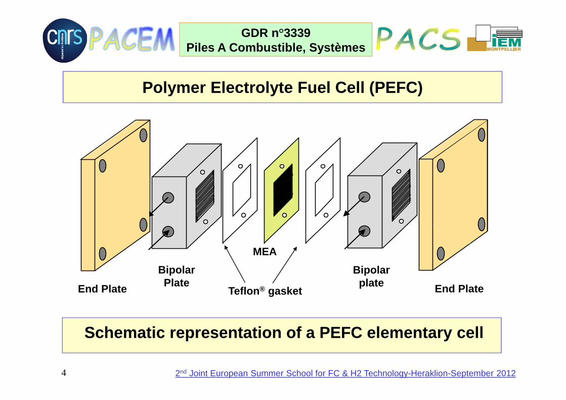
Schematic representation of a PEFC elementary cell
End Plate
BipolarPlate End Plate
Bipolarplate
Teflon ® gasket
MEA
Polymer Electrolyte Fuel Cell (PEFC)
5
GDR n°3339Piles A Combustible, Systèmes
2nd Joint European Summer School for FC & H2 Technology-Heraklion-September 2012
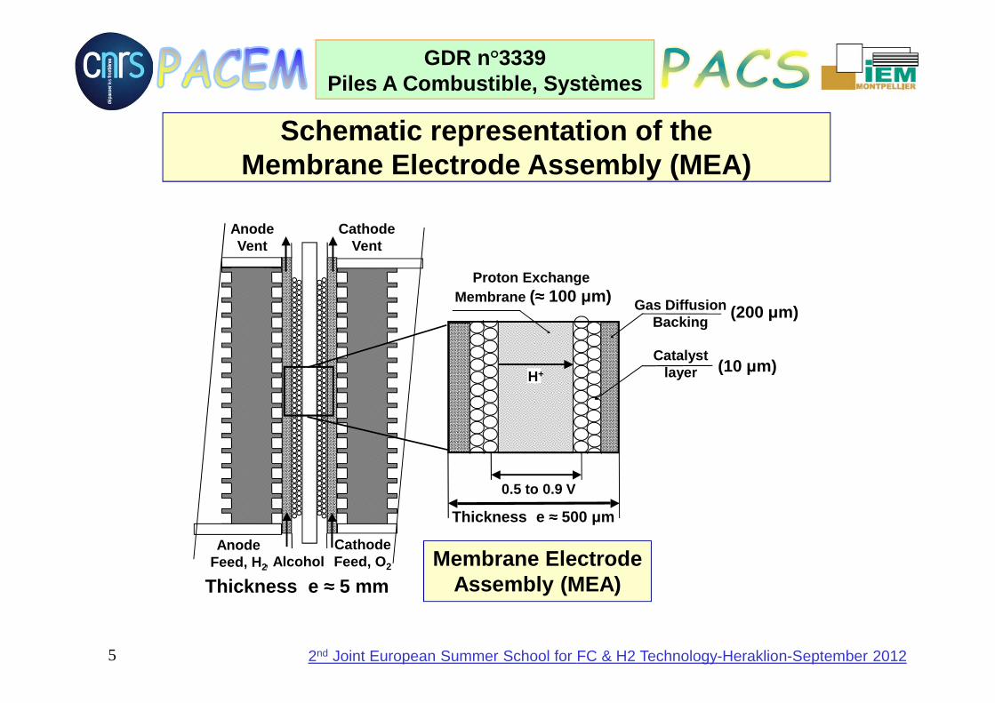
Schematic representation of the Membrane Electrode Assembly (MEA)
AnodeVent
CathodeVent
AnodeFeed, H2
CathodeFeed, O2
0.5 to 0.9 V
Gas DiffusionBacking
Proton Exchange Membrane (≈≈≈≈ 100 µm)
CatalystlayerH+
Membrane Electrode Assembly (MEA)Thickness e ≈≈≈≈ 5 mm
Thickness e ≈≈≈≈ 500 µm
(10 µm)
(200 µm)
, Alcohol
6
GDR n°3339Piles A Combustible, Systèmes
2nd Joint European Summer School for FC & H2 Technology-Heraklion-September 2012
Development of new proton exchange membranes with improved
conductivity and thermal stability

7
GDR n°3339Piles A Combustible, Systèmes
2nd Joint European Summer School for FC & H2 Technology-Heraklion-September 2012
Chemical stability : 60 000h - 80°C Good ionic conductivity : 4.10-2 to 10-1 S.cm-1
Easy to solubilize ~ colloidal dispersion Complex synthesis : high cost (400 $/m2), recycling difficulty Good mechanical properties, but low Tg (110°C) Permeation to methanol / swelling
Nafion (Dupont de Nemours - 1966)
Nafion is the Reference Membrane: Sulfonic Acid Functionalized Perfluorinated Polymer

8
GDR n°3339Piles A Combustible, Systèmes
2nd Joint European Summer School for FC & H2 Technology-Heraklion-September 2012
Structures of perfluoronated sulfonic acid ionomers
Polymer structures
DOW
CF2CF2CFCF2CF2
O
CF2
CF2
S OO
O
H+
DUPONT NAFION®
O
CF2
CF
O
CF2CF2CF2CFCF2CF2
H+
CF2
S=OO=
O
CF2
– CF3
––
Rf-SO3- H+

9
GDR n°3339Piles A Combustible, Systèmes
2nd Joint European Summer School for FC & H2 Technology-Heraklion-September 2012
E(j) characteristics of a PEMFC elementary cell with different membranes : Dow (e = 125 µm) ; o Nafion® 115 (e = 125 µm) ; ∆ Nafion® 117 (e = 175 µm)
After K. Prater (Ballard), J. Power Sources, 29 (19 90) 239
Current density (j/A cm -2)
Cel
l vol
tage
(E/V
)
Specific resistance (R e = e / σσσσ)e.g. for Nafion ® 115 :
0.0125 cm / 0.125 S cm -1
≈≈≈≈ 0.1 ΩΩΩΩ cm 2
><><><><
DUPONT NAFION®
O
CF2
CF
O
CF2CF2CF2CFCF2CF2
H+
CF2
S=OO=
O
CF2
– CF3
––
Dow

10
GDR n°3339Piles A Combustible, Systèmes
2nd Joint European Summer School for FC & H2 Technology-Heraklion-September 2012
jo = 10-8 A cm -2; Re = 0,15 ΩΩΩΩ cm 2; j l = 1,3 A cm -2
jo = 10-8 A cm -2; Re = 0,30 ΩΩΩΩ cm 2; j l = 1,2 A cm -2
0,000
0,200
0,400
0,600
0,800
1,000
1,200
0 0,25 0,5 0,75 1,0 1,25 1,5Current density j/A cm -2
Ohmic drop R e j
Charge transfer activation
Mass transferactivation
0,7
Eeq = 1,23 V
0,4
Cel
l vol
tage
E/V
Cell voltage E(j) = E +(j) – E–(j) - Re j
Influence of the membrane specific resistance (Re = e/σ) on the cell voltage-current density characteristics E(j)

11
GDR n°3339Piles A Combustible, Systèmes
2nd Joint European Summer School for FC & H2 Technology-Heraklion-September 2012
The polyetheretherketones (PEEK) family: ether and ketone units
Good stability, conductivity, low cost; Can be used for hybrid membranes
Polyethersulfone: ether and sulfone units
Good stability, conductivity, low permeability to methanol, water retention at high T

12
GDR n°3339Piles A Combustible, Systèmes
2nd Joint European Summer School for FC & H2 Technology-Heraklion-September 2012
Para-Phenylene family
Sulfonated Polyimides (sPI)
Polybenzimidazole (PBI)

13
GDR n°3339Piles A Combustible, Systèmes
2nd Joint European Summer School for FC & H2 Technology-Heraklion-September 2012
Copolymers: e.g. sulfonated polytrifluorostyrene (B allard)
Irradiation grafting: sulfonated polystyrene on ETFE structure
Co / terpolymerisation of fluoro-aromatic monomers with VF2, HFP or CTFE
Good performances, 14 000 h at 70°C
Other means of fabrication :
14
GDR n°3339Piles A Combustible, Systèmes
2nd Joint European Summer School for FC & H2 Technology-Heraklion-September 2012
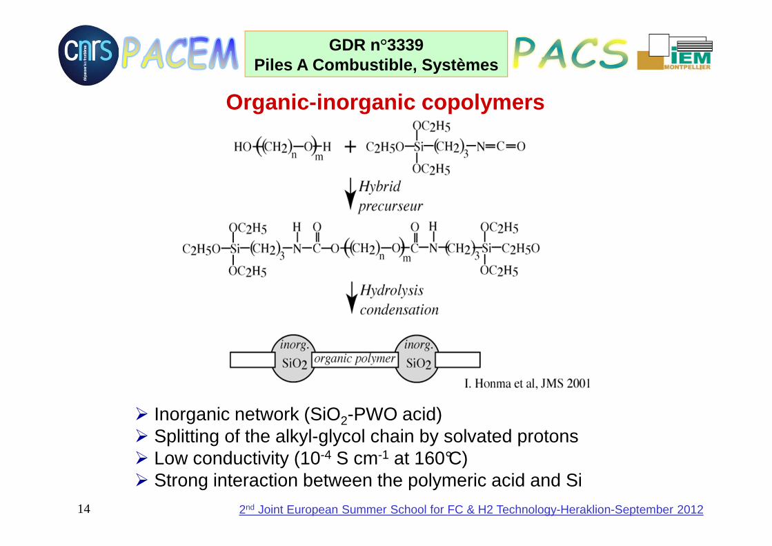
Organic-inorganic copolymers
Inorganic network (SiO2-PWO acid) Splitting of the alkyl-glycol chain by solvated protons Low conductivity (10-4 S cm-1 at 160°C) Strong interaction between the polymeric acid and Si
15
GDR n°3339Piles A Combustible, Systèmes
2nd Joint European Summer School for FC & H2 Technology-Heraklion-September 2012
N
N
N
N
n
HH
+
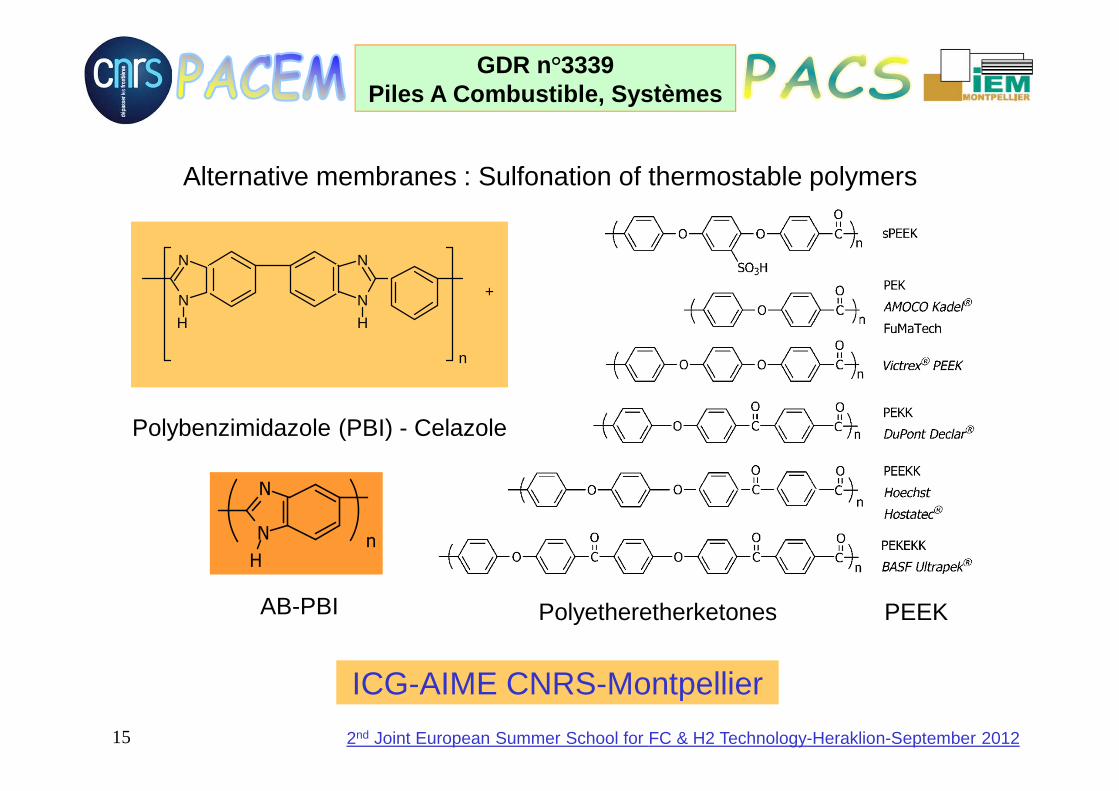
Polyetheretherketones PEEK
Polybenzimidazole (PBI) - Celazole
Alternative membranes : Sulfonation of thermostable polymers
N
N
H
n
AB-PBI
ICG-AIME CNRS-Montpellier

16
GDR n°3339Piles A Combustible, Systèmes
2nd Joint European Summer School for FC & H2 Technology-Heraklion-September 2012
Ionic Conductivity
0.01
0.1
0 20 40 60 80 100
σ (
S/c
m)
T (°C)
sPEEK
sPEEK-ZrP 40%
sPEEK-ZrP 20%
Conductiviy at 100 % relative humidity Conductivity at 100 °C
0,001
0,01
0,1
65 70 75 80 85 90 95 100
PEEK-S
PEEK-S-ZrP30
cond
uctiv
ity (
Scm
-1)
relative humidity (%)
ICG-AIME CNRS-Montpellier

17
GDR n°3339Piles A Combustible, Systèmes
2nd Joint European Summer School for FC & H2 Technology-Heraklion-September 2012
Ionic conductivity of sulfonated PEEKsSTRUCTURE IEC
(meqH+/g)σ
(S/cm)
1,31,6
0,5 10-2
0,7 10-2
BLOCK CO-POLYMER
1,31,6
1,6
0,6 10-2
1,1 10-2
1,6 10-2
1,3 0,2 10-2
NAFION 2,4 10-2
OO
CH3
CH3
O
HO3S
SO3H
OO
CH3
CH3
O
OO
CF3
CF3
O
HO3S
SO3H
OO
CF3
CF3
O
OO
OO
CH3
CH3
O
SO3H
HO3S
OO
CH3
CH3
O
CNRS-Lyon Solaize

18
GDR n°3339Piles A Combustible, Systèmes
2nd Joint European Summer School for FC & H2 Technology-Heraklion-September 2012
Alternative Membranes : POST MODIFICATION of POLYME RSCF3
CF3
O O
OO
AR
CF3
CF3
O O
OO
AR
SO3H
SO3H
O
O O
SO3H
SO3H
CH3
CH3
O
POLYMERIZATION of SULFONATED MONOMERS
CNRS-Lyon Solaize
19
GDR n°3339Piles A Combustible, Systèmes
2nd Joint European Summer School for FC & H2 Technology-Heraklion-September 2012
Development of new electrode materials with improved
electrocatalytic properties

20
GDR n°3339Piles A Combustible, Systèmes
2nd Joint European Summer School for FC & H2 Technology-Heraklion-September 2012
Influence of the catalytic properties of electrodes (exchange current density jo) on the cell voltage E(j)
0,000
0,200
0,400
0,600
0,800
1,000
1,200
0 0,25 0,5 0,75 1,0 1,25 1,5Current density j/A cm -2
Cel
l vol
tage
E/V
Ohmic drop R e jCharge transfer
overvoltage
Eeq = 1,23 V
Mass transfer overvoltage
0,7
E(j) = E+(j) - E–(j) - Re j = Eeq – (|η|η|η|ηc(j) |||| + |η|η|η|ηa(j) ||||) - Re j
0,4 0,9
jo = 10-8 A cm -2; Re = 0,15 ΩΩΩΩ cm 2; j l = 1,3 A cm -2
jo = 10-6 A cm -2; Re = 0,15 ΩΩΩΩ cm 2; j l = 1,4 A cm -2
21
GDR n°3339Piles A Combustible, Systèmes
2nd Joint European Summer School for FC & H2 Technology-Heraklion-September 2012
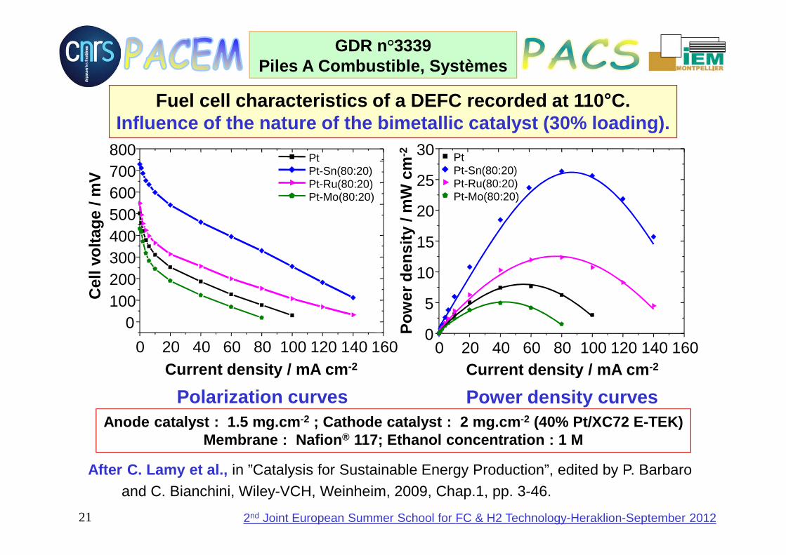
Fuel cell characteristics of a DEFC recorded at 110 °C.Influence of the nature of the bimetallic catalyst (30% loading).
Anode catalyst : 1.5 mg.cm -2 ; Cathode catalyst : 2 mg.cm -2 (40% Pt/XC72 E-TEK)Membrane : Nafion ® 117; Ethanol concentration : 1 M
0 20 40 60 80 100 120 140 160
0100200300400500600700800
PtPt-Sn(80:20)Pt-Ru(80:20)Pt-Mo(80:20)
Cel
l vol
tage
/ m
V
Current density / mA cm -2
Polarization curves Power density curves
0 20 40 60 80 100 120 140 1600
5
10
15
20
25
30 PtPt-Sn(80:20)Pt-Ru(80:20)Pt-Mo(80:20)
Pow
er d
ensi
ty /
mW
cm
-2
Current density / mA cm -2
After C. Lamy et al., in ”Catalysis for Sustainable Energy Production”, edited by P. Barbaro and C. Bianchini, Wiley-VCH, Weinheim, 2009, Chap.1, pp. 3-46.

22
GDR n°3339Piles A Combustible, Systèmes
2nd Joint European Summer School for FC & H2 Technology-Heraklion-September 2012
Activation barrier for an electrochemical reaction :K is the decrease in activation energy due to the ele ctrode catalyst,so that the effect of the electrocatalyst is contai ned in, ∆∆∆∆G+
o, i.e. in jo
Principle of Electrocatalysis : activation of elect rochemical (interfacial) reactions by both the electrode potential and the e lectrode material
a0aa
acta j
jln
Fnα
RTη ====
c0cc
actc j
jln
Fnα
RTη ====
Abcissa along the reaction path
Ene
rgy
chan
ge
RTη F n α
oRTη F n α
RTG
-ioii e j e e c k F n c E)k(T, F n v F n j
o
================
++++∆∆∆∆
with e c k F n j RTG
-ioo
o++++∆∆∆∆
====

23
GDR n°3339Piles A Combustible, Systèmes
2nd Joint European Summer School for FC & H2 Technology-Heraklion-September 2012
HOW TO DESIGN PLURI-METALLIC PT-BASED ELECTROCATALYSTS FOR MULTI-STEP MULTI-ELECTRON TRANSFER REACTIONS, SUCH AS METHANOL OXIDATION:
CH3OH + H2O →→→→ CO2 + 6 H+ + 6 e-
Platinum allows the breaking of the C -H bonds .
The role of the other metals may be as follows: * to provide OH (or O) species necessary for complete
oxidation (towards CO2) at low electrode potentials,
* to avoid the formation of poisoning species,
* to allow the oxidation of the poisoning intermediates at lower potentials,
* to break the C -C bond at low temperature and low electrode potentials (e.g. for ethanol oxidation).
24
GDR n°3339Piles A Combustible, Systèmes
2nd Joint European Summer School for FC & H2 Technology-Heraklion-September 2012
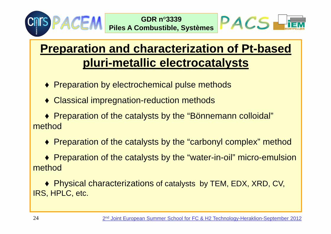
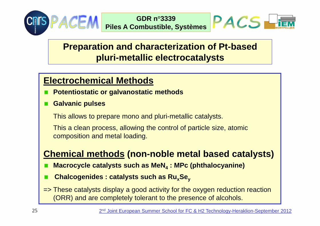
Preparation and characterization of Pt-based pluri-metallic electrocatalysts
♦ Preparation by electrochemical pulse methods
♦ Classical impregnation-reduction methods
♦ Preparation of the catalysts by the “Bönnemann colloidal” method
♦ Preparation of the catalysts by the “carbonyl complex” method
♦ Preparation of the catalysts by the “water-in-oil” micro-emulsion method
♦ Physical characterizations of catalysts by TEM, EDX, XRD, CV,IRS, HPLC, etc.
25
GDR n°3339Piles A Combustible, Systèmes
2nd Joint European Summer School for FC & H2 Technology-Heraklion-September 2012
Preparation and characterization of Pt-based pluri-metallic electrocatalysts
Electrochemical MethodsPotentiostatic or galvanostatic methods
Galvanic pulses
This allows to prepare mono and pluri-metallic catalysts.
This a clean process, allowing the control of particle size, atomic composition and metal loading.
Chemical methods (non-noble metal based catalysts)Macrocycle catalysts such as MeN 4 : MPc (phthalocyanine)
Chalcogenides : catalysts such as Ru xSey
=> These catalysts display a good activity for the oxygen reduction reaction (ORR) and are completely tolerant to the presence of alcohols.

26
GDR n°3339Piles A Combustible, Systèmes
2nd Joint European Summer School for FC & H2 Technology-Heraklion-September 2012
Chemical methods (platinum -based catalysts)Colloïdal route (Bönnemann):
MeCln+nNalk4[BEt3H] Me[Nalk4Cl]n +nBEt3 +n/2H2
This allows to control the particle size, atomic composition and structure of the catalyst (alloying, decoration, etc.)
Carbonyl route :
Na2PtCl6 + SnCl4 + NaCH3CO2 [+ CO (24h)] + [C (12h)] PtxSny/C
This allows to control the particle size and atomic composition of the catalysts
Water-in-oil method :
H2PtCl6aq(Brij®30)+NaBH4aq(Brij ®30) + [C (0,5 – 2h)]Pt/C
Easy process, allowing to control the particle size, atomic composition and structure of the catalysts.
⇒ Pluri-metallic anodic catalysts for the oxidation of alcohols and carbon monoxide (reformate gas) and alcohol tolerant cathodic catalysts.
Physical methods (platinum -based catalysts) : PVDPlasma sputtering : this allows to reduce the platinum loading (< 100 µg/cm2)

27
GDR n°3339Piles A Combustible, Systèmes
2nd Joint European Summer School for FC & H2 Technology-Heraklion-September 2012
EXPERIMENTAL CHARACTERIZATION OF Pt-BASED ELECTROCATALYSTS
♦♦♦♦ Transmission Electron Microscopy (TEM) :- Observation of the morphology and determination of the particle size- Determination of the particle composition by Energy Dispersive Analysis of X-rays (EDX)♦♦♦♦ X-Ray Diffraction (XRD) :- Determination of the catalyst structure and lattice parameters- Evaluation of the particle size of the catalyst ♦♦♦♦ Cyclic Voltammetry (CV) :- Determination of the true surface area- Evaluation of the electrocatalytic activity♦♦♦♦ Infrared Reflectance Spectroscopy (IRS) :- Identification of the adsorbed species and reaction products by “in situ” Infrared Reflectance Spectroscopy (SNIFTIRS and SPAIRS)♦♦♦♦ Chromatographic Analysis (HPLC) of the reaction pro ducts
28
GDR n°3339Piles A Combustible, Systèmes
2nd Joint European Summer School for FC & H2 Technology-Heraklion-September 2012
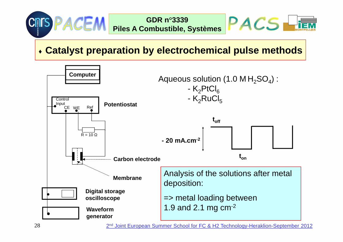
Digital storage oscilloscope
Waveform generator
PotentiostatControl Input
CE RefWE
R = 10 Ω
Membrane
Carbon electrode
Computer
- 20 mA.cm -2
toff
ton
Aqueous solution (1.0 M H2SO4) :- K2PtCl6- K2RuCl5
Analysis of the solutions after metal deposition:
=> metal loading between 1.9 and 2.1 mg cm-2
♦ Catalyst preparation by electrochemical pulse metho ds

29
GDR n°3339Piles A Combustible, Systèmes
2nd Joint European Summer School for FC & H2 Technology-Heraklion-September 2012
XRD TEM EDX
Physical characterization of Pt 1-xRux catalysts prepared by the electrochemical deposition method

30
GDR n°3339Piles A Combustible, Systèmes
2nd Joint European Summer School for FC & H2 Technology-Heraklion-September 2012
• Advantages :– Clean process– Easy and reproducible process– Controlled atomic composition– Controlled particle size– Possibility of manufacturing FC electrodes
• Disadvantages :– Low faradic yield (close to 10%) due to H2 evolution– Long duration of experiments– Only formation of alloy compounds
Advantages and disadvantages of catalysts prepared by electrochemical deposition

31
GDR n°3339Piles A Combustible, Systèmes
2nd Joint European Summer School for FC & H2 Technology-Heraklion-September 2012
20 nm 50 nm
Loading limited to 10 wt. %
HVulcan XC72 C
O
OH
NaClO
Vulcan XC72
NH3
CO
O-NH4+
Vulcan XC72
CO
O-
Pt2+Vulcan XC72
Pt(NH3)42
+
2
PtVulcan XC72
∆∆∆∆H2
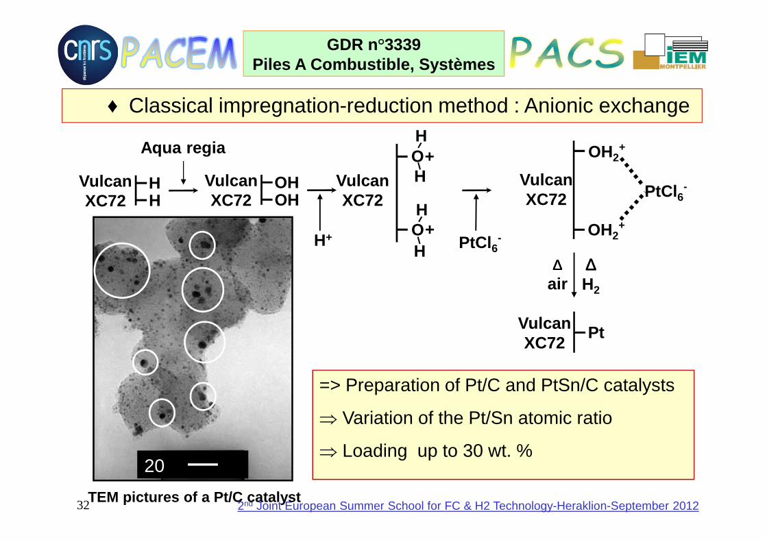
♦ Classical impregnation-reduction method : Cationic exchange
32
GDR n°3339Piles A Combustible, Systèmes
2nd Joint European Summer School for FC & H2 Technology-Heraklion-September 2012
=> Preparation of Pt/C and PtSn/C catalysts
⇒ Variation of the Pt/Sn atomic ratio
⇒ Loading up to 30 wt. %
Aqua regia
H+ PtCl 6-
∆∆∆∆air
∆∆∆∆H2
HVulcan XC72 H
OHVulcan XC72 OH
OH
HVulcan XC72
+
OH
H+
PtCl 6-Vulcan
XC72
OH2+
OH2+
PtVulcan XC72
20 nmTEM pictures of a Pt/C catalyst
♦ Classical impregnation-reduction method : Anionic exchange

33
GDR n°3339Piles A Combustible, Systèmes
2nd Joint European Summer School for FC & H2 Technology-Heraklion-September 2012
♦♦♦♦ Preparation of Pt-based plurimetallic electrocataly sts by the “Bönnemann colloidal” method
Preparation of the reducing agent(tetraalkylammonium triethylborohydride):
N(CnH2n+1)4Br + KB(C2H5)3H → N(CnH2n+1)4[B(C2H5)3H] + KBr↓
Preparation of the mono and bimetallic colloid precursors :
PtCl2 + 2 N(CnH2n+1)4[B(C2H5)3H] →Pt[N(CnH2n+1)4Cl]2 + 2 B(C2H5)3↓ + H2↑
m PtCl2 + n XCly + (2m + yn) N(CnH2n+1)4[B(C2H5)3H] →PtmXn[N(CnH2n+1)4Cl](2m + yn) + (2m + yn) B(C2H5)3↓ + (2m+ yn)/2 H2↑

34
GDR n°3339Piles A Combustible, Systèmes
2nd Joint European Summer School for FC & H2 Technology-Heraklion-September 2012
Pt-X/XC72 catalyst
+Pt VulcanXC-72
VulcanXC-72
Pt
Pt
Pt
T = 300°C
air
Pt/XC72 catalystcolloid particles
+
Pt
X
VulcanXC-72
VulcanXC-72
Pt
Pt
Pt
X
X
XT = 300°C
air
X = Ru, Sn, Cr, Fe…
X
X
Deposition of the colloid particles on a carbon pow der

35
GDR n°3339Piles A Combustible, Systèmes
2nd Joint European Summer School for FC & H2 Technology-Heraklion-September 2012
Deposition of the colloid particles on a carbon powder (Vulcan XC72)
Codeposition
Colloid Pt
Colloid Ru
x Pt[N(alk) 4Cl]2 + y Ru[N(alk) 4Cl]3
300°C XC72 air
Ptx+ Ruy/C
Coreduction
xPtCl 2 + yRuCl 3 +(2x+3y)N(alk) 4BEt3H
300°C XC72 air
Ptx-Ruy/C
PtxRuy[N(alk) 4Cl] (2x+3y)
Mixture of catalysts
Colloid Pt
Colloid Ru
Pt/C Ru/C
xPt/C+ yRu/C
300°C XC72 air
300°C XC72 air

36
GDR n°3339Piles A Combustible, Systèmes
2nd Joint European Summer School for FC & H2 Technology-Heraklion-September 2012
Codeposition Pt+Ru/C
1.0 1.5 2.0 2.5 3.0 3.5 4.0 mean particle size/nm
400
300
200
100
0Num
ber
of p
arti
cles
40 60 80
Inte
nsit
y / a
.u.
2θ (°)
ExperimentalPtRu
simulation of Pt+Ru
40 60 80 2θθθθ(°)
n
dnd i
ii
TEM
∑
=
Coreduction Pt-Ru/C
From XRD measurement: alloy character
1.0 1.5 2.0 2.5 3.0 3.5 4.0 mean particle size/nm
500 400 300 200 100
0
Num
ber
of p
arti
cles
Characterization of Pt 0.8Ru0.2 catalysts prepared by the colloidal method

37
GDR n°3339Piles A Combustible, Systèmes
2nd Joint European Summer School for FC & H2 Technology-Heraklion-September 2012
Catalysts d TEMCrystallographic
structure
Pt/XC72 2.2 fcc
Pt+Ru/XC72 (80:20)
2.1Pt fcc + Ru hc in
interaction
Pt-Ru/XC72 (80:20)
1.9 fcc alloy
Pt/XC72+Ru/XC72 (80:20)
Pt(2.1)+Ru(1.5) Pt fcc + Ru hc
Ru/XC72 1.5Hexagonal compact (hc)
Characterization of Pt 0.8Ru0.2 catalysts prepared by the colloidal method

38
GDR n°3339Piles A Combustible, Systèmes
2nd Joint European Summer School for FC & H2 Technology-Heraklion-September 2012
TEM image of a Vulcan supportedPt-Sn(90:10)/XC72 catalyst
(with a metal loading of 30%)prepared by the colloidal method
Particle size distribution of aPt-Sn(90:10)/XC72 catalyst
(based on the observation of 1005 particles)
Mean diameter : 2.4 ± 0.3 nm
0 1 2 3 4 5 60
50
100
150
200
250
300
Num
ber
of p
artic
les
Particle size / nm
Characterization of a Pt 0.9Sn0.1 catalyst prepared by the colloidal method
39
GDR n°3339Piles A Combustible, Systèmes
2nd Joint European Summer School for FC & H2 Technology-Heraklion-September 2012
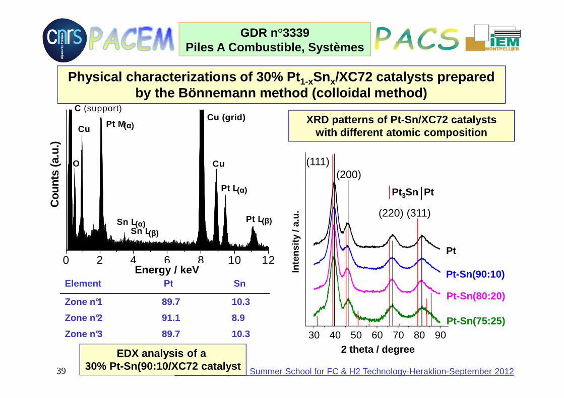
EDX analysis of a 30% Pt-Sn(90:10/XC72 catalyst
XRD patterns of Pt-Sn/XC72 catalystswith different atomic composition
30 40 50 60 70 80 90
Pt3Sn Pt
Pt-Sn(75:25)
Pt-Sn(80:20)
Pt-Sn(90:10)
Pt
Inte
nsity
/ a.
u.
2 theta / degree
(111)(200)
(220) (311)
Physical characterizations of 30% Pt 1-xSnx/XC72 catalysts prepared by the Bönnemann method (colloidal method)
0 2 4 6 8 10 12
Sn LPt L
Pt L
Cu
CuCu (grid)
Sn L
Pt M
O
C (support)
Cou
nts
(a.u
.)
Energy / keV
(α)
(α)
(β)
(β)(α)
Energy / keVElement Pt Sn
Zone n°1 89.7 10.3
Zone n°2 91.1 8.9
Zone n°3 89.7 10.3

40
GDR n°3339Piles A Combustible, Systèmes
2nd Joint European Summer School for FC & H2 Technology-Heraklion-September 2012
ElectrocatalystdTEM
/ nmDispersion/ %
dXRD
/ nmAtomic composition (EDX)
S / m2.g-1
30% Pt/XC72 2.4 44 2.1 / 39
30% Pt-Sn(90:10)/XC72 2.4 45 1.9 89.7 / 10.3 24
60% Pt-Sn(90:10)/XC72 2.8 40 3.4 89.8 / 10.2 11
30% Pt-Sn(80:20)/XC72 2.7 41 2.1 80.4 / 19.6 15
30% Pt-Sn(75:25)/XC72 2.9 38 2.0 74.1 / 25.9 8
Values of the physical and electrochemical paramete rsof different Pt-Sn electrocatalysts prepared
by the colloidal method

41
GDR n°3339Piles A Combustible, Systèmes
2nd Joint European Summer School for FC & H2 Technology-Heraklion-September 2012
Preparation of a Pt carbonyl complex :
3n [PtClz]2- + (3nz/2 + 3n + 1) CO + (3nz – 6n + 2) OH- →
[Pt3(CO)6]n2- + 3nz Cl- + (3nz/2 - 3n + 1) CO2 + (3nz/2 - 3n + 1) H2O
Preparation of bimetallic Pt1-xMx carbonyl complex :
3n(1-x) [PtCl6]2- + 3nx [MClz]2- + [3n (4 - 6x + zx)/2 + 6n + 1)] CO
+ [3n (4 - 6x + zx) + 2)] OH- → [(Pt1-xMx)3(CO)6]n2- + 3n [6(1 – x) + zx)] Cl-
+ [3n (4 - 6x + zx)/2 + 1)] CO2 + [3n (4 - 6x + zx)/2 + 1)] H2O
Deposition of the metallic particles on Vulcan XC72 :
♦ Preparation of Pt-based plurimetallic electrocataly sts by the “carbonyl complex” method
+ 2 Na+
Water rinsing
Then heating at 300°Cunder H 2 for 1h30

42
GDR n°3339Piles A Combustible, Systèmes
2nd Joint European Summer School for FC & H2 Technology-Heraklion-September 2012
Physical characterization of a (4:1)Pt-Co/C catalyst prepared by the carbonyl complex method
EDX
1,0 1,5 2,0 2,5 3,0 3,5 4,0 4,5 5,0 5,50
10
20
30
40
50
60
70
80
90
<d>=2.40 +/- 1,06 nm
Num
ber
of p
artic
les
Particle size (nm)
Pt-Co (4:1)/C
TEM image
High resolution TEM
XRD
30 40 50 60
Pt-Co (4:1)
Inte
nsity
/ u.
a.
Angle (2 θθθθ) / degree

43
GDR n°3339Piles A Combustible, Systèmes
2nd Joint European Summer School for FC & H2 Technology-Heraklion-September 2012
Physical characterization of (2:1)Pt-Ni/C prepared b y the carbonyl complex method
Particle size distribution (from TEM) EDX analysisTEM micrograph
Catalyst Nominal atomic Experimental Particle size Dispersioncomposition (%) composition (%) (nm) (%)

44
GDR n°3339Piles A Combustible, Systèmes
2nd Joint European Summer School for FC & H2 Technology-Heraklion-September 2012
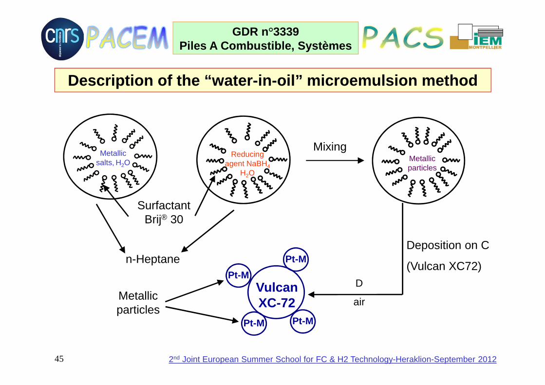
♦♦♦♦ Preparation of Pt-based plurimetallic electrocatalysts by the “water-in-oil” method
PtCl 62- + 4 e- → Pt(s) + 6 Cl -
BH4- + 3 H2O → BO3
3- + 2 H2 + 6 H+ + 4 e-
___________________________________________________
(PtCl 62-)aq + 3H2O + (BH4
-)aq
→ Pt(s) + BO 33- + 2 H2 + 6 H+ + 6 Cl-
45
GDR n°3339Piles A Combustible, Systèmes
2nd Joint European Summer School for FC & H2 Technology-Heraklion-September 2012
Description of the “water-in-oil” microemulsion metho d
Deposition on C
(Vulcan XC72)
Reducing agent NaBH4
H2O
SurfactantBrij® 30
n-Heptane
Metallic salts, H2O
MixingMetallic particles
Metallicparticles
D
airVulcanXC-72
Pt-M
Pt-M
Pt-M
Pt-M
46
GDR n°3339Piles A Combustible, Systèmes
2nd Joint European Summer School for FC & H2 Technology-Heraklion-September 2012
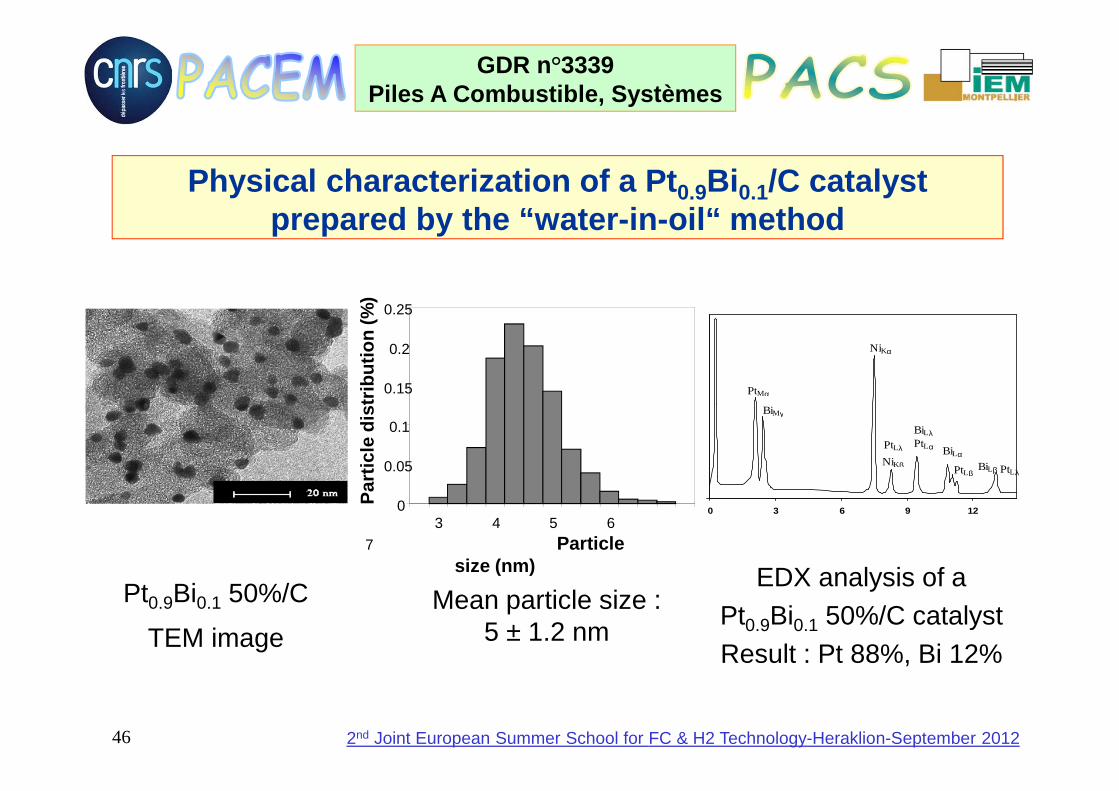
Physical characterization of a Pt 0.9Bi 0.1/C catalyst prepared by the “water-in-oil“ method
Pt0.9Bi0.1 50%/C
TEM imageMean particle size :
5 ± 1.2 nm
00 3 6 9 12
PtMα
BiMγ
PtLλ
NiKβ
NiKα
PtLα
BiLλ
PtLβ
BiLα
BiLβ PtLλ
EDX analysis of a Pt0.9Bi0.1 50%/C catalystResult : Pt 88%, Bi 12%
3 4 5 6
7 Particle size (nm)
0
0.05
0.1
0.15
0.2
0.25
Par
ticle
dis
trib
utio
n (%
)
47
GDR n°3339Piles A Combustible, Systèmes
2nd Joint European Summer School for FC & H2 Technology-Heraklion-September 2012
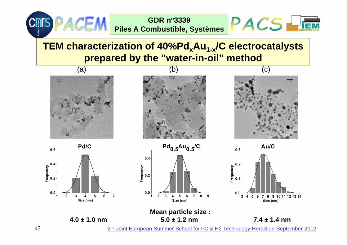
TEM characterization of 40% PdxAu1-x/C electrocatalysts prepared by the “water-in-oil” method
(a) (b) (c)
Mean particle size : 4.0 ±±±± 1.0 nm 5.0 ±±±± 1.2 nm 7.4 ±±±± 1.4 nm
48
GDR n°3339Piles A Combustible, Systèmes
2nd Joint European Summer School for FC & H2 Technology-Heraklion-September 2012
Electrocatalysts for fuel cell reactions at low temperatures (< 90°C)
♦ Electrocatalytic oxidation of hydrogen
♦ Electrocatalysts for CO oxidation
♦ Electrocatalytic reduction of dioxygen
49
GDR n°3339Piles A Combustible, Systèmes
2nd Joint European Summer School for FC & H2 Technology-Heraklion-September 2012
M-H bond strength / kcal.mol-1
-Lo
g j o
for
the
h.e.
r. (j o
in A
.cm
-2)
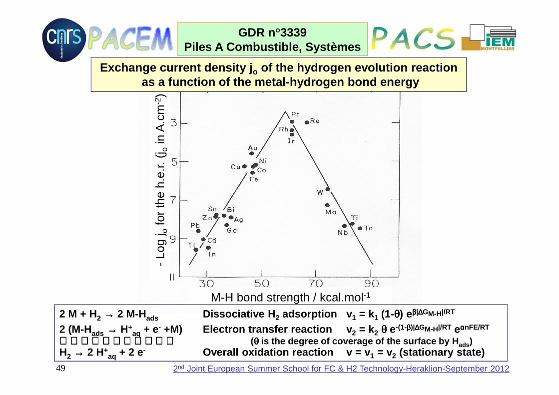
2 M + H2 →→→→ 2 M-Hads Dissociative H 2 adsorption v 1 = k1 (1-θθθθ) eββββ|∆∆∆∆GM-H|/RT
2 (M-Hads →→→→ H+aq + e- +M) Electron transfer reaction v 2 = k2 θθθθ e-(1-ββββ)|∆∆∆∆GM-H|/RT eααααnFE/RT
(θθθθ is the degree of coverage of the surface by H ads)H2 →→→→ 2 H+
aq + 2 e- Overall oxidation reaction v = v 1 = v2 (stationary state)
Exchange current density j o of the hydrogen evolution reactionas a function of the metal-hydrogen bond energy

50
GDR n°3339Piles A Combustible, Systèmes
2nd Joint European Summer School for FC & H2 Technology-Heraklion-September 2012
0,0
0,2
0,4
0,6
0,8
1,0
1,2
1,4
0,0
0,2
0,4
0,6
0,8
1,0
1,2
0,0 0,5 1,0 1,5 2,0 2,5 3,0 3,5
P /
W c
m-2
E /
V
j / A cm -2
Cel
l vol
tage
E/V
Current density j / A cm -2
∆∆∆∆ : cathode and anode prepared in LACCO, 0.35 mg Pt cm -2 (Bönnemann colloidal method) : cathode LACCO 0.35 mg Pt cm -2 and anode LACCO+GREMI 0.1 mg Pt cm -2 (Plasma PVD)O : anode LACCO 0.35 mg Pt cm -2 and cathode LACCO+GREMI 0.1 mg Pt cm -2 (Plasma PVD)
Polarization and power density curves of a PEMFC ob tained with a homemade MEA. Tcell=85°C, Thuma=80°C, Thumc =35°C, fa=600 ml mn -1, fc=400 ml mn -1, pa=pc=3 bar

51
GDR n°3339Piles A Combustible, Systèmes
2nd Joint European Summer School for FC & H2 Technology-Heraklion-September 2012
0.0 0.2 0.4 0.6 0.8 1.0
0.0
0.5
1.0
1.5
2.0
2.5
j / m
A c
m-2
E / V vs. RHE
Pt (bulk)
PAni/Pt
PAni/Pt-Ru
PAni/Pt-Sn
PAni/Pt-Ru-Sn
0.0 0.2 0.4 0.6 0.8 1.0
0.0
0.5
1.0
1.5
2.0
2.5
j / m
A c
m-2
E / V vs. RHE
Pt (bulk)
PAni/Pt
PAni/Pt-Ru
PAni/Pt-Sn
PAni/Pt-Ru-Sn
Electro-oxidation of CO on different Pt-based electrodes dispersed in polyaniline (PAni) : () bulk Pt ; (– – – ) PAni/Pt ; (• • • •) PAni/Pt-Ru ; (• – • – • –) PAni/Pt-Sn ; (- - - -) PAni/Pt-Ru-Sn
Pt + CO →→→→ Pt-COads CO adsorptionM + H2O →→→→ M-OHads + H+
aq + e- Dissociative adsorption of waterPt-COads + M-OHads →→→→ Pt + M + CO2 + H+
aq + e- Surface reactionCO + H2O →→→→ CO2 + 2 H+
aq + 2 e- Overall oxidation reaction

52
GDR n°3339Piles A Combustible, Systèmes
2nd Joint European Summer School for FC & H2 Technology-Heraklion-September 2012
Single Cell performance plots for Pt/C, PtRu/C and PtSn/C at 85°C at several CO concentrations: () 0 ppm; (O) 5 ppm; () 20 ppm; () 50 ppm and () 100 ppm.
After Mukerjee et al.,Electrochim. Acta, 44 (1999) 3283
Effect of a few ppm of CO on the E(j)
characteristics of a H2/O2 PEMFC fed with a
reformate gas
53
GDR n°3339Piles A Combustible, Systèmes
2nd Joint European Summer School for FC & H2 Technology-Heraklion-September 2012
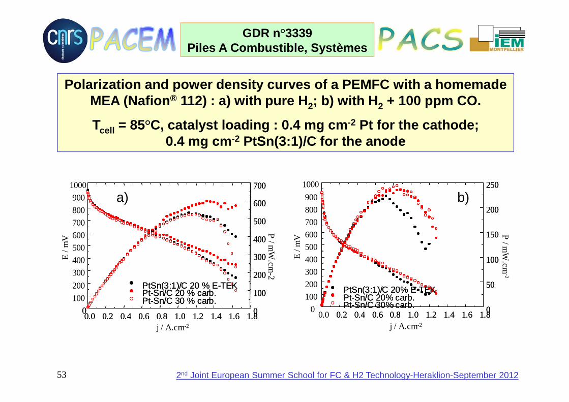
Polarization and power density curves of a PEMFC wi th a homemade MEA (Nafion ® 112) : a) with pure H 2; b) with H 2 + 100 ppm CO.
Tcell = 85°C, catalyst loading : 0.4 mg cm -2 Pt for the cathode; 0.4 mg cm -2 PtSn(3:1)/C for the anode
100
200
300
400
500
600
700
800
900
1000
E /
mV
j / A.cm-2
0.0 0.2 0.4 0.6 0.8 1.0 1.2 1.4 1.6 1.80
PtSn(3:1)/C 20 % E-TEKPt-Sn/C 20 % carb.Pt-Sn/C 30 % carb.
0
100
200
300
400
500
600
700
P /m
W.cm
-2100
200
300
400
500
600
700
800
900
1000
E /
mV
j / A.cm-2
0.0 0.2 0.4 0.6 0.8 1.0 1.2 1.4 1.6 1.80
PtSn(3:1)/C 20 % E-TEKPt-Sn/C 20 % carb.Pt-Sn/C 30 % carb.
0
100
200
300
400
500
600
700
0.0 0.2 0.4 0.6 0.8 1.0 1.2 1.4 1.6 1.80
PtSn(3:1)/C 20 % E-TEKPt-Sn/C 20 % carb.Pt-Sn/C 30 % carb.
0
100
200
300
400
500
600
700
P /m
W.cm
-2
0.00
100
200
300
400
500
600
700
800
900
1000
E /
mV
j / A.cm-2
0.2 0.4 0.6 0.8 1.0 1.2 1.4 1.6 1.8
PtSn(3:1)/C 20% E-TEKPt-Sn/C 20% carb.Pt-Sn/C 30% carb. 0
50
100
150
200
250
P /m
W.cm
-2
0.00
100
200
300
400
500
600
700
800
900
1000
E /
mV
j / A.cm-2
0.2 0.4 0.6 0.8 1.0 1.2 1.4 1.6 1.8
PtSn(3:1)/C 20% E-TEKPt-Sn/C 20% carb.Pt-Sn/C 30% carb. 0
50
100
150
200
250
0.2 0.4 0.6 0.8 1.0 1.2 1.4 1.6 1.8
PtSn(3:1)/C 20% E-TEKPt-Sn/C 20% carb.Pt-Sn/C 30% carb. 0
50
100
150
200
250
P /m
W.cm
-2
a) b)

54
GDR n°3339Piles A Combustible, Systèmes
2nd Joint European Summer School for FC & H2 Technology-Heraklion-September 2012
The rather difficult oxygen reduction kinetics
O2 (O2)surf (H2O2)ads H2O
(H2O2)surf H2O2
H2O
k1
k2
k ’2
k3
k4
k5k ’
5
Possible reaction paths for oxygen reduction
55
GDR n°3339Piles A Combustible, Systèmes
2nd Joint European Summer School for FC & H2 Technology-Heraklion-September 2012
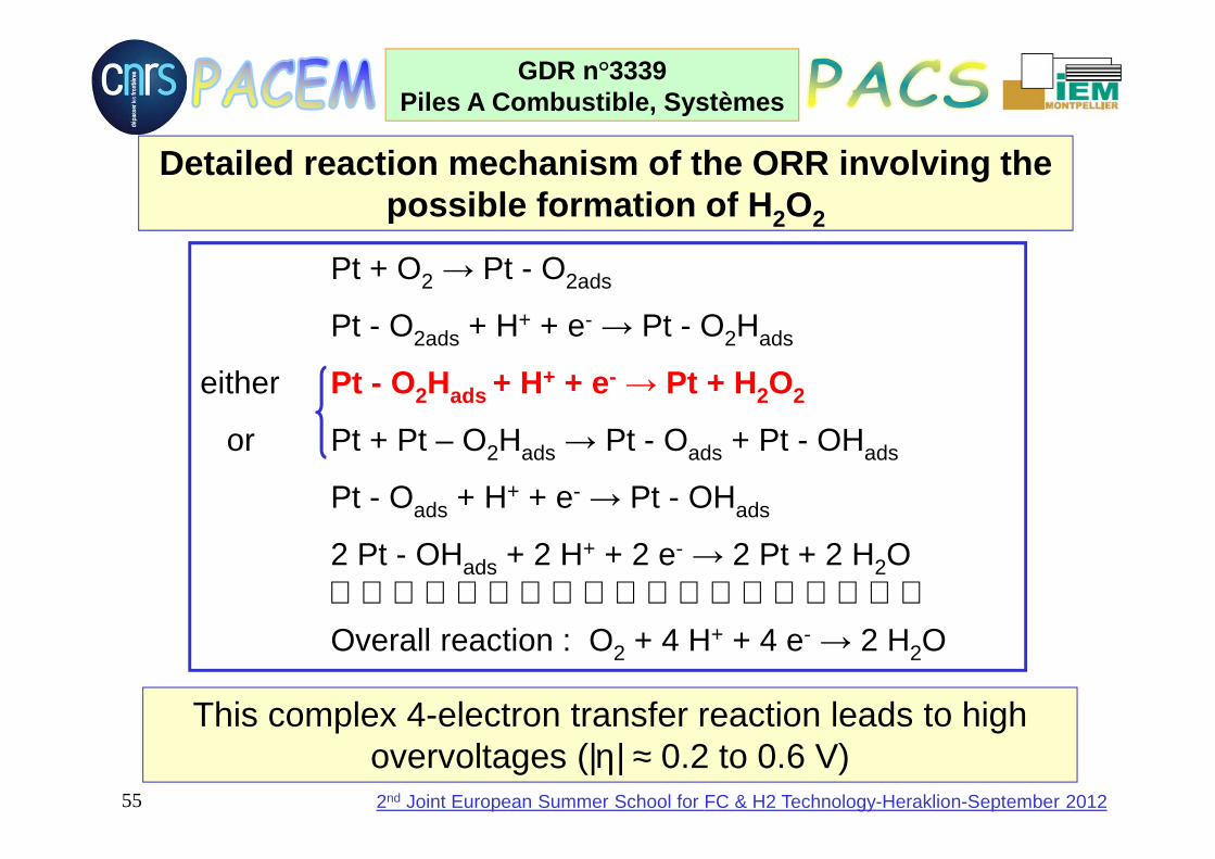
Detailed reaction mechanism of the ORR involving th e possible formation of H 2O2
Pt + O2 → Pt - O2ads
Pt - O2ads + H+ + e- → Pt - O2Hads
either Pt - O2Hads + H+ + e- → Pt + H2O2
or Pt + Pt – O2Hads → Pt - Oads + Pt - OHads
Pt - Oads + H+ + e- → Pt - OHads
2 Pt - OHads + 2 H+ + 2 e- → 2 Pt + 2 H2OOverall reaction : O2 + 4 H+ + 4 e- → 2 H2O
This complex 4-electron transfer reaction leads to high overvoltages (|η| ≈ 0.2 to 0.6 V)

56
GDR n°3339Piles A Combustible, Systèmes
2nd Joint European Summer School for FC & H2 Technology-Heraklion-September 2012
-45
-40
-35
-30
-25
-20
-15
-10
-5
0
0,2 0,4 0,6 0,8 1 1,2
E/ V vs. RHE
j/ m
A m
g-1
Pt Pt/C
Pt-Cr10/C
Pt-Cr20/C
Pt-Cr30/C
Pt-Cr40/C
Mass Activity for Oxygen reduction ; effect of Cr c omposition0.5 M H2SO4 ; ; T= 25°C ; v = 5 mV s -1 ; ΩΩΩΩ = 2500 rpm .
After Hui Yang et al. J. Phys. Chem. B, 108(6), 193 8, 2004.

57
GDR n°3339Piles A Combustible, Systèmes
2nd Joint European Summer School for FC & H2 Technology-Heraklion-September 2012
After Xiong et al., 204th ECS Meeting, Orlando, Oct ober 2003
Current density (A/cm 2)
Cel
l pot
entia
l (V
)
Comparison of the performances of several Pt-Co alloys in a PEMFC single cell (alloys prepared by hydrogen reduction of cobalt hydroxide)
Effect of Pt alloying on the oxygen reduction overv oltage
58
GDR n°3339Piles A Combustible, Systèmes
2nd Joint European Summer School for FC & H2 Technology-Heraklion-September 2012
N
N
N
N
N
N N N
M
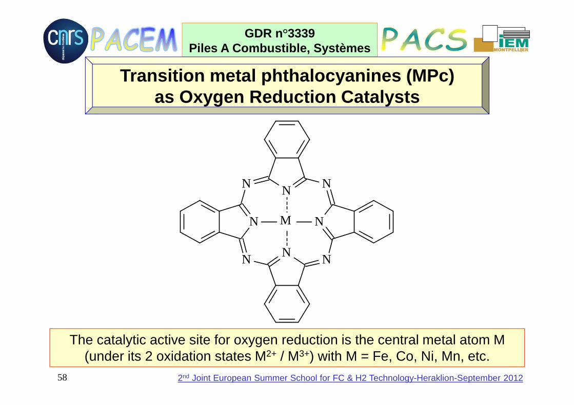
Transition metal phthalocyanines (MPc)as Oxygen Reduction Catalysts
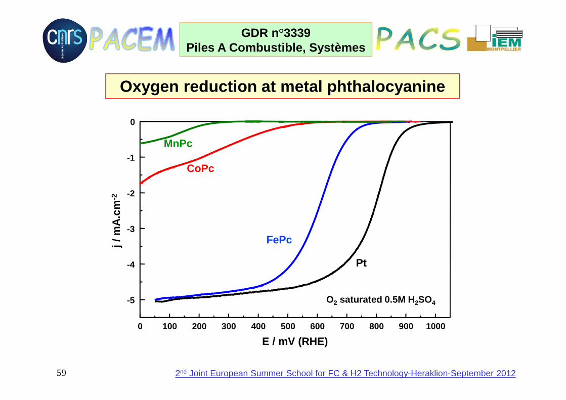
The catalytic active site for oxygen reduction is the central metal atom M(under its 2 oxidation states M2+ / M3+) with M = Fe, Co, Ni, Mn, etc.
59
GDR n°3339Piles A Combustible, Systèmes
2nd Joint European Summer School for FC & H2 Technology-Heraklion-September 2012
E / mV (RHE)0 100 200 300 400 500 600 700 800 900 1000
-5
-4
-3
-2
-1
0j /
mA
.cm
-2
Pt
FePc
CoPc
MnPc
O2 saturated 0.5M H 2SO4
Oxygen reduction at metal phthalocyanine

60
GDR n°3339Piles A Combustible, Systèmes
2nd Joint European Summer School for FC & H2 Technology-Heraklion-September 2012
Effect of methanol on oxygen reduction atmetal phthalocyanine
PtH2SO4 0,5M O2
saturated
PtH2SO4 0,5M ; O2
saturated+ MeOH 1M
FePcH2SO4 0,5M O2
saturated
FePcH2SO4 0,5M O2
saturated+ MeOH 1M
200 300 400 500 600 700 800 900 1000 1100
-5
-4
-3
-2
-1
0
j / m
A.c
m-2
E / mV (ERH)E / mV (RHE)
j / m
A.c
m-2

61
GDR n°3339Piles A Combustible, Systèmes
2nd Joint European Summer School for FC & H2 Technology-Heraklion-September 2012
0 5 10 15 20 25 30 350
100
200
300
400
500
600
700
j / mA.cm -2
E /
mV
0
1
2
3
4
5
6
7
P / m
W.cm
-2
PAni + FeTsPc
FePc / C
Anodes: PtRu/C E-Tek ; 5M MeOH ; room temperatureFePc / C (O2) P < 1 mW cm -2
PAni + FeTsPc (O 2) P = 6 mW cm -2
Direct Methanol Fuel Cell with a FePc cathode
62
GDR n°3339Piles A Combustible, Systèmes
2nd Joint European Summer School for FC & H2 Technology-Heraklion-September 2012
References[1] J. O’M BOCKRIS, S. SRINIVASAN, Fuel Cells : thei r electrochemistry,
McGraw Hill Book Co., New York, 1969.[2] K. KORDESH, G. SIMADER, Fuel cells and their app lications, VCH, Weinheim, 1996.[3] C. LAMY, J-M. LEGER, Electrocatalysis with Elect ron-conducting Polymers
Modified by Noble Metal Nanoparticles, in Catalysis and Electrocatalysis at Nanoparticle Surfaces, A. Wieckowski, E. Savinova, C. Vayenas (Eds.), Marcel Decker Inc. (New-York), chap 25 (2002) pp 907-929.
[4] Handbook of Fuel Cells, W. Vielstich, H. Gast eiger, A Lamm (Eds.), Wiley, Chichester (UK), Volume 1, "Fundamentals and Survey of Systems", (2003)pp.323-334. Volume 2 to 6, 2003-2009.
[5] J.-M. Léger, C. Coutanceau, C. Lamy, "Electro catalysis for the direct alcohol fuelcell", in “Fuel Cell Catalysis“, M. Koper, A. Wieck owski (Eds.), Wiley-VCH, Weinheim, 2009, Chap.11, pp. 337-367.
[6] C. Lamy, C. Coutanceau, N. Alonso-Vante, “Met hanol tolerant cathode catalystsfor DMFC”, in “Electrocatalysis of Direct Methanol Fuel Cells”, H. Zhang, H. Liu (Eds.), Wiley-VCH, Weinheim, 2009, Chap 7, pp. 257- 314.
[7] C. Coutanceau, S. Baranton, C. Lamy, "Determi nation of Reaction Mechanisms Occurring at Fuel Cell Electrocatalysts Using Elect rochemical Methods, Spectroelectrochemical Measurements and Analytical Techniques", in "Modern Aspects of Electrochemistry", P. Balbuena, V.R. Sub ramanian (Eds.), Springer, New
York, Vol. 50, 2010, Chap 11, pp. 397-501.

63
GDR n°3339Piles A Combustible, Systèmes
2nd Joint European Summer School for FC & H2 Technology-Heraklion-September 2012
ACKNOWLEDGEMENTS
We acknowledge the support of different research agencies :
CNRS, Institute of Chemical Sciences
Agence de l'Environnement et de la Maîtrise de l'EnergieADEME/ AGRICE Programme),
Ministry of Research (French Fuel Cell Network),
to which we are greatly indebted.

64
GDR n°3339Piles A Combustible, Systèmes
2nd Joint European Summer School for FC & H2 Technology-Heraklion-September 2012
Thank you for Thank you for Thank you for Thank you for
your kind attentionyour kind attentionyour kind attentionyour kind attention