basics of interferometry - cmi · basics of interferometry. 2 ccd. interferometer. 4 typical...
TRANSCRIPT

BASICS OF INTERFEROMETRY

2
CCDCCD

Interferometer

4
Typical Interferometer
••The expanded beam The expanded beam exiting from the light exiting from the light source is divided by a source is divided by a BeamsplitterBeamsplitter into two into two beams.beams.
••One beam is reflected One beam is reflected from the Reference from the Reference Mirror, and the other one Mirror, and the other one from the Sample.from the Sample.
••These two beams are These two beams are recombined by the recombined by the BeamsplitterBeamsplitter to interfere.to interfere.
••The imaging lens The imaging lens images the interferogram images the interferogram onto the CCD camera.onto the CCD camera.
CCDCCD
Sample
Reference Mirror
BeamsplitterTest arm
Reference arm
Optical Path Difference (OPD)- difference in optical path lengths that
beams travel in Reference and Test arms.
5
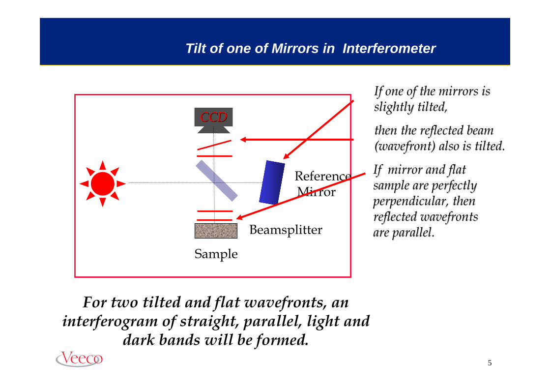
Tilt of one of Mirrors in Interferometer
If one of the mirrors is If one of the mirrors is slightly tilted, slightly tilted,
then the reflected beam then the reflected beam (wavefront) also is tilted.(wavefront) also is tilted.
For two tilted and flat wavefronts, an interferogram of straight, parallel, light and
dark bands will be formed.
CCDCCD
Reference Mirror
Beamsplitter
Sample
If mirror and flat If mirror and flat sample are perfectly sample are perfectly perpendicular, then perpendicular, then reflected wavefronts reflected wavefronts are parallel. are parallel.

Interferogram

7
Interferogram for Flat Wavefronts with Tilt
Two interfering Two interfering wavefrontswavefronts
InterferogramInterferogram, , (interference pattern (interference pattern or fringe pattern)or fringe pattern)
Interference between two wavefronts is constructive at these multiple λ points, destructive at others, forming an interferogram.
Intensity profile Intensity profile of interferogram.of interferogram.
Fringe spacing corresponds to λ path difference between wavefronts.
Tested beam(wavefront)
Reference beam (wavefront).
Multiple λ distances between wavefronts, where λ is the wavelength of the source.
44λλλλ 22λλ 33λλ

8
Change in Tilt Causes Change in Number of Fringes.
Reference
Test
The number and spacing of fringes changes with tilt.
NULL FRINGES
When wavefronts are parallel then When wavefronts are parallel then the fringes are the fringes are nullednulled and almost and almost uniform intensity is visible in the uniform intensity is visible in the
field of view. field of view.
Press EnterPress Enter

Shape of fringes

10
When one wavefront is spherical and the other is flat, and in adWhen one wavefront is spherical and the other is flat, and in addition dition there is some tilt between interfering wavefronts, then the frinthere is some tilt between interfering wavefronts, then the fringes ges will be curved. When tilt is not present, the fringes are circuwill be curved. When tilt is not present, the fringes are circular.lar.
Interferograms for Spherical Sample

11
The fringes can represent a concave wavefront instead convex The fringes can represent a concave wavefront instead convex wavefront as on previous slide.wavefront as on previous slide.
Interferograms for Spherical Sample

12
Typical Interferogram for
Fringes Phase map
Flat Surface
λλ 22λλ 33λλ

13
Typical Interferogram for
Fringes Phase map
Spherical Surface

14
Typical Interferogram for
Fringes Phase map
Cylindrical Surfaces

Interference Microscope

16
# of fringes ≈ 2λ/∆λ
Filter Bandwidth and Number of Fringes
• Narrow bandwidth filter (3nm) (in PSI)
• Medium bandwidth filter (40nm)
• Wide bandwidth filter (300nm) - white light (in VSI)

17
Microscope DiagramDigitized IntensityData
Beamsplitter
Detector Array
Illuminator
MicroscopeObjective
Translator
MirauInterferometer
Light Source
ApertureStop
FieldStop
Filter
Interference
Filters all but the red light from white light
of halogen lamp
Sample
18
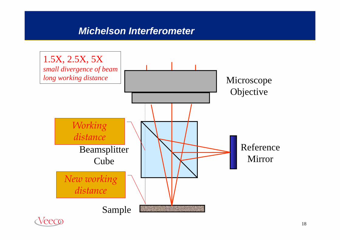
Michelson Interferometer
1.5X, 2.5X, 5Xsmall divergence of beamlong working distance Microscope
Objective
Sample
BeamsplitterCube
ReferenceMirror
Working distance
New working distance

19
Mirau Interferometer
Reference
MicroscopeObjective
Sample
BeamsplitterPlate

20
Mirau Interferometer for Small Magnification?
Reference
MicroscopeObjective
Sample
BeamsplitterPlate
1.5X, 2.5X, 5Xsmall divergence of beamlong working distance
LARGE central obscuration
21

22
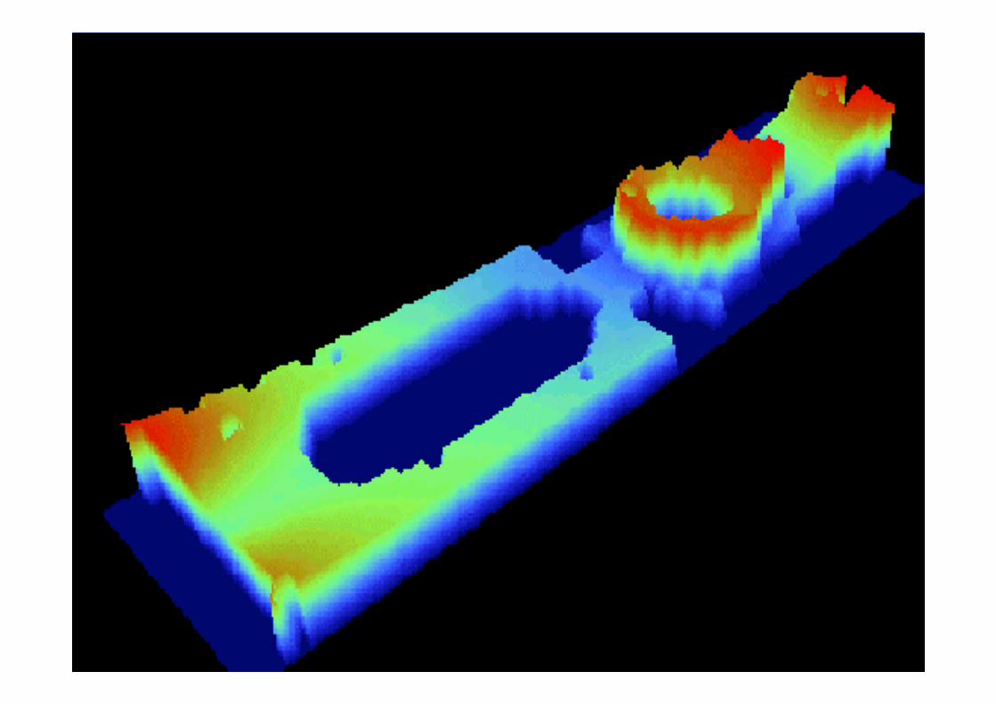
Rt: 2.62 umRa: 255.14 nmRq: 344.18 nmSurface Stats:

23

24

25

26

27

28

29
PV: 23.64 umRMS: 7.23 umSurface Stats:

30