bardon - kohler co.resources.kohler.com/plumbing/kohlerindia/pdf/k8787c02sc.pdf · -4-2. remove the...
TRANSCRIPT
-1-
BARDON
TOUCHLESS URINAL SENSOR
INSTALLATION INSTRUCTIONS
K-8787T-C02(DC/ )
K-8787T-C04(AC/ )
�
�
�
Please read these instructions carefully to familiarizeyourself with the required tools, materials, and installationsequences. Follow the sections that pertain to yourparticular installation. This will help you avoid costlymistakes. In addition to proper installation, read alloperation and safety instructions.All information in these instructions is based upon thelatest product information available at the time ofpublication. Kohler China reserves the right to makechanges in product characteristics, packaging, oravailability at any time without notice.These instructions contain important care, cleaning, andwarranty information -
.please leave instructions for the
consumer
�
�
� -
�
�
�
�
�
�
�
�
�
�
�
�
�
�
Open end/adjustable wrenches
Tape measure
Basin wrench
Pipe wrench
Square
Level
Pliers
Socket wrench with sockets
Screw driver
Seal tape
Connection wire
Wire cutter
Insulation tape
Bushing
�
�
�
�
�
�
�
�
�
�
�
�
�
�
/
RECOMMENDED TOOLS AND MATERIALSRECOMMENDED TOOLS AND MATERIALS
Model8787T-C02(DC)
8787T-C04(AC)
Power
4 AA size alkaline batteries(8787T-C02)
" "
Temperature Environmental temperature: 1 to 60
220V AC 50/60Hz(8787T-C04)
Starting pressure 0.05~0.7MPa
Sensing distance80cm away from sensing window(adjustable)
Testing time About 2 seconds (or set to 5 seconds)
SENSOR SPECIFICATIONSENSOR SPECIFICATION
Note: the sensing distance in the table is measured with a
30 30cm white board as the reflecting surface.2
8787T-C02( )
8787T-C04( )
220V AC 50/60Hz(8787T-C04)
4 5 (AA 4)(8787T-C02)
: 1 ~60
0.05~0.7MPa
80cm( )
2 ( 5 )
, 2007�
Copyright Kohler China Ltd., 2007�
18 E 201206
1022895-T01-C
-2-
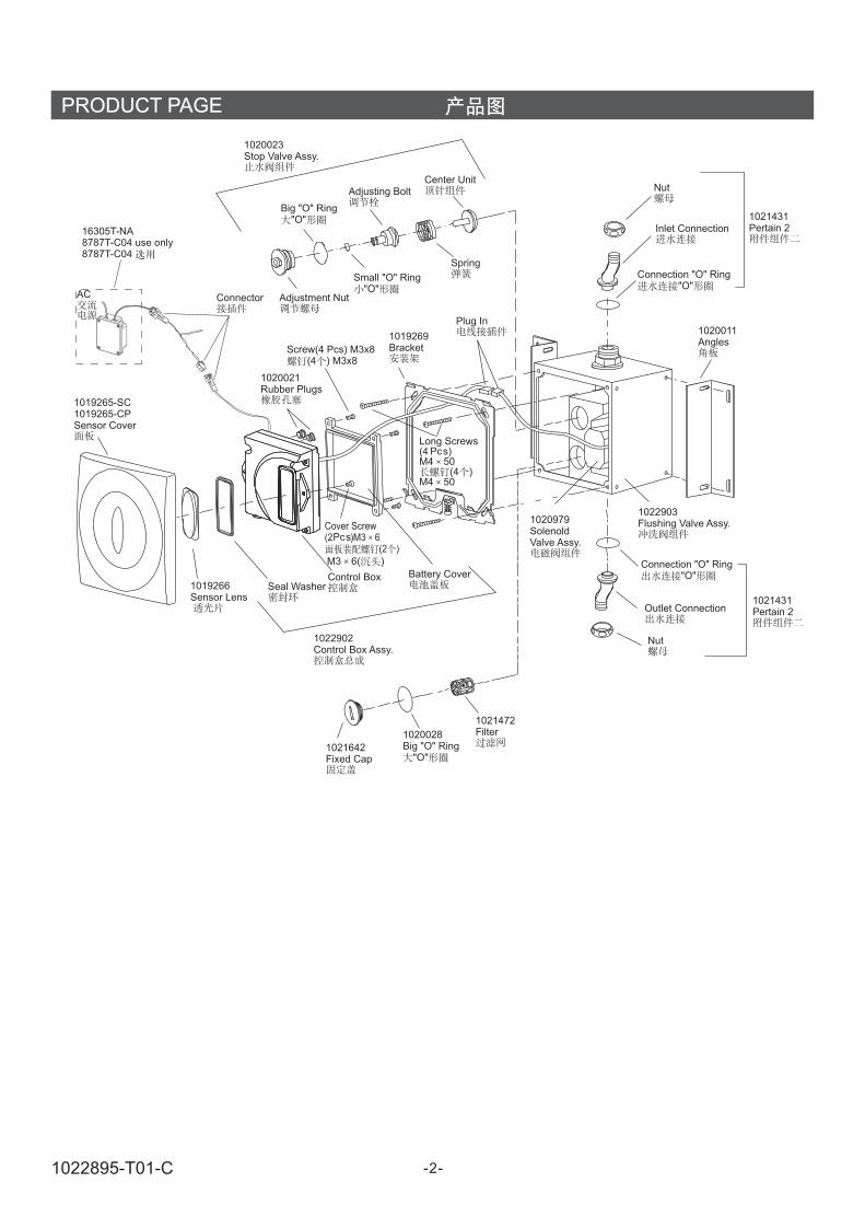
PRODUCT PAGE
1020023Stop Valve Assy.
Big "O" Ring"O"
Adjusting BoltCenter Unit
16305T-NA8787T-C04 use only8787T-C04
Connector
Spring
Nut
Inlet Connection
Connection "O" Ring"O"
1021431Pertain 2
Screw(4 Pcs) M3x8(4 ) M3x8
1019269Bracket
Plug In
1020021Rubber Plugs
1020011Angles
Long Screws(4 )M4 50
(4 )M4 50
M3 6( )
1022903Flushing Valve Assy.1020979
SolenoldValve Assy.
1019266Sensor Lens
Seal WasherControl Box Battery Cover
1022902Control Box Assy.
Fixed Cap1021642
1020028Big "O" Ring
"O"
1021472Filter
Connection "O" Ring"O"
Outlet Connection1021431Pertain 2
Small "O" Ring""O
Cover Screw(2 )M3 6
(2 )
Pcs
Pcs
Nut
AC
1019265-SC1019265-CPSensor Cover
Adjustment Nut
1022895-T01-C

-3-
ROUGHING-IN
K-5016T-ET K-5016T-ER
UNIT: mm
Notice: a. The dimensions above are just for reference.
b. The connection take between the outlet connection
and urinal is not supplied in this package.
a.
b.
Notice: To ensure an effective flush performance,
strongly recommended inner diameter of
water supply (including water meter, valve, etc.)
is no less than 25mm, and supplied water
pressure (sensor inlet dynamic pressure) is
0.18MPa ~0.55MPa (Go with K-5016T).
() 25mm (
) 0.18MPa ~0.55MPa ( K-5016T)
97+200 158
158
320 40
445 "2 N.P.S. TAP
R1/2
97+200
160
158
158
320 40
76
5
445
R1/2
3/4 SPUD"
2 N.P.S. TAP"
2"1/
INSTALLATION
1.
Notice
Determine the installation location per rough-in dimensions.Chisel out a slot and install the supply tubing. Turn off thewater supply. The depth of the slot is no less than 105mm,see the figure to the right for rough-in dimensionrequirement.While installing 8787T-C04(AC), chisel out the slotindicated in the dot line area of figure right for installation ofbushing.
: installation location:a. No light shall enter or be reflected into the
sensing window.b. No reflectible objects in front of the sensing
window (e.g., mirror, polishing stainlesssteel and some other polished plate).
c. No strong ultraviolet radiation orelectromagnetic field nearby.
1.
105mm
8787T-C04( )
a.
b. (
)
c.
Installation Site
160
50
90
110
85
110
160
50
42
Install Bushing
1022895-T01-C
-4-
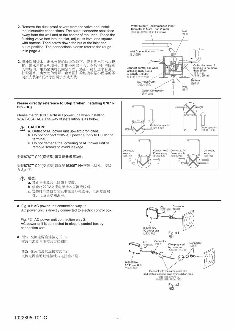
2. Remove the dust-proof covers from the valve and installthe inlet/outlet connections. The outlet connector shall faceaway from the wall and at the center of the urinal. Place theflushing valve box into the slot, adjust its level and squarewith battens. Then screw down the nut at the inlet andoutlet position. The connections please refer to the rough-in in page 3.
2.
3
Water Supply(Recommended InnerDiameter Is More Than 25mm)
( 25mm)
Inlet Connection
Battens
Outlet Connection
Nut
È25.400
Nut
Outer diameter ofbushing is no morethan 25mm
25mm
Connect control box whileinstalling 8787T-C04
8787T-C04
AC Power Unit
Please directly reference to Step 3 when installing 8787T-C02 (DC).
Please match 16305T-NA AC power unit when installing8787T-C04 (AC). The way of installation is as below.
a. Outlet of AC power unit upward prohibited.b. Do not connect 220V AC power supply to DC wiring
terminal.c. Do not damage the covering of AC power unit or
remove screws to avoid leakage.
CAUTION:Outlet downwards
Outlet upwards
Connect tosensor
Connect to ACPower supply
A. 1
2
Connect to ACPower supply
8787T-C02( ) 3
8787T-C04( ) 16305T-NA
a.
b. 220V
c.
A. Fig. #1: AC power unit connection way 1:
AC power unit is directly connected to electric control box.
Fig. #2 : AC power unit connection way 2:
AC power unit is connected to electric control box by
connection wire.
Connect tosensor
Fig. #11
Fig. #22
AC
AC Connector
16305T-NAAC power unit
16305T-NAAC Power Unit
Connector
Wire preparedby customer
Connect with the same color ,and protect connect area by insulation tape.
wire
Connector
1022895-T01-C

-5-
Connect 220V AC220V
Bushing
B
CAUTION:
. When installing the AC power unit in cassette, pleaselayout the bushing according to Fig. #3, and thread thewire through the bushing.Fig. #3: Connection sketch AC power unit install incassette.
One AC power unit can supply two sensorsat most.
B.
3
Fig. #33
C
CAUTION:
. When installing the power unit on the ceiling, pleaselayout bushing according to Fig. #4 and thread wirethrough the bushing.Fig. #4: Connection sketch while installing power unit on
the ceiling.
One AC power unit can supply two sensorsat most.
Bushing
AC Power UnitCeiling
Notice: a. Keep the connector away from water.b. Don t mistake the direction of inlet and
outlet.’
c. Do not connect the DC output of AC powerunit to AC power supply.
d. Do not connect to power supply whileinstalling. Connection line is not supplied.AC connection wire with insulating sleevingis recommended. Wire of which thenominal section area of conductor is notless than 0.5mm is also recommended.DC connection line use wire of which thenominal section area is not less than0.3mm . It is cut according to actedinstallation requirements(The length of cutwire is recommended less than 10m).
e. The head AC power supply must beprotected with appropriate fuse.
f. Please confirm the AC power supply andwater supply should be shut off beforemaintaining the products with AC powerrelated.
g. Don lose the connection O rings.
2
2
't
: a.b.c.
d.
0.5mm
0.3mm( 10m)
e.
f.
2
2
g. O
C.
4
Fig. #44
1022895-T01-C
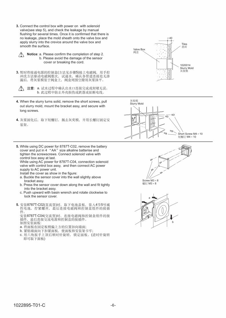
3.
Notice
Connect the control box with power on with solenoidvalve(see step 5), and check the leakage by manualflushing for several times. Once it is confirmed that there isno leakage, place the mold sheath onto the valve box andapply slurry into the crevice around the valve box andsmooth the surface.
: a. Please confirm the completion of step 2.b. Please avoid the damage of the sensor
cover or breaking the cord.
3. ( 5)
a.
b.
4. When the slurry turns solid, remove the short screws, pull
out slurry mold, mount the bracket assy, and secure with
long screws.
4.
5. While using DC power for 8787T-C02, remove the batterycover and put in 4 AA size alkaline batterise andtighten the screwscrews. Connect solenoid valve withcontrol box assy at last.While using AC power for 8787T-C04, c
and then connect AC powersupply to AC power unit.Install the cover as show in the figure:a. Buckle the sensor cover into the wall slightly above
bracket assy.b. Press the sensor cover down along the wall and fit tightly
into the bracket assy.c. Push upward with basin wrench and rotate clockwise to
lock the sensor cover.
onnection solenoidvalve with control box assy,
5. 8787T-C02( ) 4 5
8787T-C04( )
a.b.c. (
)
Valve Box
Tiles
1020014Slurry Mold
40
Slurry Mold
Short Screw M4 10M4 10
Screw M3 8M3 8
a
b
-6-1022895-T01-C

Notice: a. Don t mistake the polar of the batteries and
don t mix new and used batteries together.When no enough power, the indicatorwill flash continuously (20 times at most).When out of power, the indicator will flashevery 2 seconds and the sensor will notwork until new batteries are supplied. Whenchanging, remove the battery cover and putin new batteries. No need to reset theprogram after the battery changed.
b. Put on clean gloves when install sensorcover to avoid surface injury by cement orsand.
'
'
a.
( 20 )
2
b.
Indicator
Battery Indicatorc
90o
INSTALLATION IN OTHER METHODSINSTALLATION IN OTHER METHODS
Don t use this system until the power is on for 10minutes.The sensing distance will be adjusted and the systemwill not work during this time.
Users can set the working status as needed per the tablebelow by turning on the right switch. The four status options,SW1, SW3, and SW4, have been set ON statuses and SW2has been set OFF status in the factory. After setting, plug therubber plug tightly.
Working Status
' 10
SW1 SW3 SW4 ON SW2
OFF
Switch ON OFF
S 1 (pre-flushing)W Yes(3s) No
SW2 (testing time) About 5s About 2s
SW3(flushing cycle whenno using)
24 hours 8 hours
SW4 (manual flushing) Yes No
ON OFF
SW1 ( )
SW2 ( ) 5 2
SW3( )
24 8
SW4 ( )
1 2 3 4ON
Prefabricated Board Decorating Panel
a Installation On Prefabricated Board b Installation On Decorating Panel
97+200 40
97+200
40
-7-
USER S GUIDEUSER S GUIDE
1022895-T01-C

Manual Flushing
Approach the supplied special magnetic stick (flushing controlstick) to the left part of the sensor lens. The system is now ata manual status and the indicator will flash every 2 seconds.Approach the flushing control stick to the window, it ll start toflush; approach again, stopping flushing. This status will lastfor 8 minutes until it turns to the normal working status. (Theflushing, if any , will be terminated when this status ends)
The longest flushing time is 30 seconds once.If the flushing control stick keeps near to thesensing window, the manual status will beterminated automatically and reassume thenormal working status.
.
Notice:
( )
2
8 (
)
30
30
Sensing Distance
The first 10 minutes with power supply is the time foradjusting sensing distance. Use a cross screwdriver. If this isnot accomplished within 10 minutes, shut off the power. Waitfor the indicator to stop flashing. Turn on the power supplyand repeat the procedure.
The sensing distance is set to its max. value in factory. Theangle of ultra-red radiation is 15 degrees down. It s adjustablewhen the bathroom is narrow and crowded. When adjusting,remove the panel and the rubber plug, and adjust thepotentiometer. Make sure to insert the rubber plug back firmlywhen finished.
The scope of the screwdriver which is used toadjust the induction distance should not belarger than 3.5 70mm, so as not to damagethe potenpiometer.
Notice:
10
10
15
3.5 70mm
o
Deodorizing Flushing
The urinal will take a big flush automatically when it s used 3
or 4 times in 2 minutes.2 3-4
1020016Flushing Control Stick
(Increase) (Decrease)
Flushing Volume
Adjust when required. Remove the sensor cover. Turn the
adjusting bolt to a proper place.
Adjusting Bolt
-8-1022895-T01-C
Urinal Repair
When repairing, you don t have to dismount the sensor. Coverthe sensing window with tape and work with ease.
: Don t use very adhesive tape in case the scarNotice
'
'
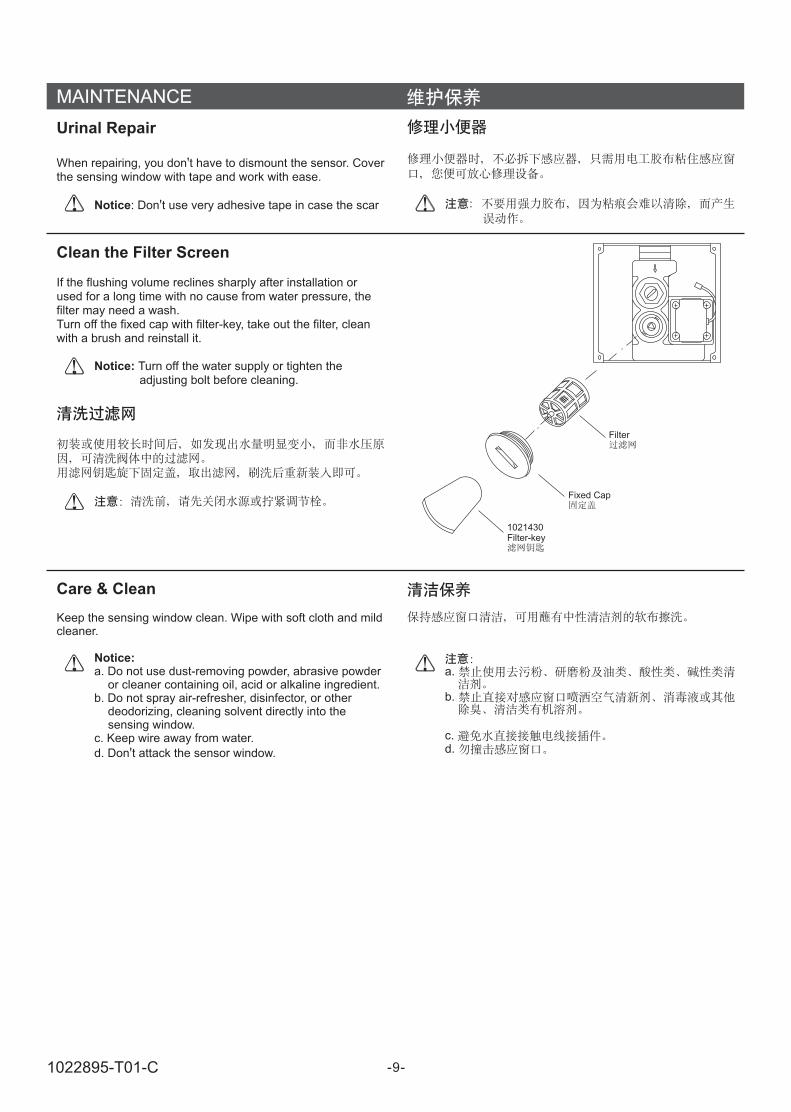
Clean the Filter Screen
If the flushing volume reclines sharply after installation orused for a long time with no cause from water pressure, thefilter may need a wash.Turn off the fixed cap with filter-key, take out the filter, cleanwith a brush and reinstall it.
Turn off the water supply or tighten theadjusting bolt before cleaning.
Notice:
Care & Clean
Keep the sensing window clean. Wipe with soft cloth and mildcleaner.
a. Do not use dust-removing powder, abrasive powderor cleaner containing oil, acid or alkaline ingredient.
b. Do not spray air-refresher, disinfector, or otherdeodorizing, cleaning solvent directly into thesensing window.
c. Keep wire away from water.
d. Don t attack the sensor window.
Notice:
'
a.
b.
c.d.
Filter
Fixed Cap
1021430Filter-key
MAINTENANCE
-9-1022895-T01-C
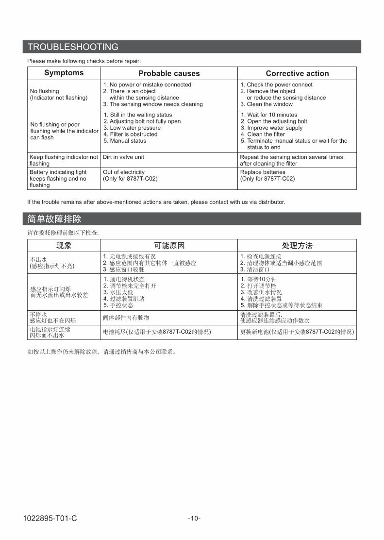
TROUBLESHOOTING
No flushing(Indicator not flashing)
No flushing or poorflushing while the indicatorcan flash
Keep flushing indicator notflashing
Battery indicating lightkeeps flashing and noflushing
1. No power or mistake connected2. There is an object
within the sensing distanc3. The sensing window needs cleaning
e
1. Still in the waiting status2. Adjusting bolt not fully open3. Low water pressure4. Filter is obstructed5. Manual status
Dirt in valve unit
Out of electricity(Only for 8787T-C02)
1. Check the power connect2. Remove the object
or reduce the sensing distance3. Clean the window
1. Wait for 10 minutes2. Open the adjusting bolt3. Improve water supply4. Clean the filter5. Terminate manual status or wait for the
status to end
Repeat the sensing action several timesafter cleaning the filter
Replace batteries(Only for 8787T-C02)
Please make following checks before repair:
If the trouble remains after above-mentioned actions are taken, please contact with us via distributor.
Symptoms Probable causes Corrective action
( )
1.2.3.
1.2.3.4.5.
( 8787T-C02 )
1.2.3.
1. 102.3.4.5.
( 8787T-C02 )
-10-1022895-T01-C

IMPORTANTCONSUMER INFORMATION
Consumer Responsibilities
1. Do not attack the sensor.
2. Do not directly flush the sensor with water. The sensor isan electronic instrument.
3. Do not let sunlight or other light source enter or bereflected into Sensor Window.
4. Do not hang on the opposite wall any reflective items orinstall light/electronic sensor such as toilet flushing sensor.
5. Do not make Sensor Window near strong ultraviolet orelectromagnetic field.
6. Keep the sensor window clean.The sensor cover can be cleaned by soft rag with neutralliquid detergent.Do not use eradicator, abrasive powder or oil, acid or alkaliliquid detergent.Do not spray air freshener, disinfectant or other kinds ofodious removing, cleaning organic liquid to the sensordirectly.
7. Urinal is designed for use with potable water.Avoid water that includes a lot of contaminants oracid/alkali water and impure water.
8. When AC power unit is connected to 220V AC powersupply, corresponding protective measures should betaken.
9. Please confirm no water penetration at the connectionarea of AC wire, and the connection area is not easy to beaffected by damp.
10. Don t connect power unit to AC power supply until thesensor installation is finished.
11. The head AC power supply must be protected withappropriate fuse.
12. Please confirm the AC power supply and water supplyshould be shut off before maintaining the products withAC power related.
13. All electrical connection must be compliance with relatedregulation and codes.
14. All installation staff should be well familiar with installationinstruction.
’
1.
2.
3.
4.( )
5.
6.
7.
8. 220V
9.
10.
11.
12.
13.
14.
-11-1022895-T01-C