b0097 - roboclaw 2 channel 15a motor controller data sheet
TRANSCRIPT

B0097 - RoboClaw 2 Channel 15A Motor ControllerData Sheet
B0097 - RoboClaw 2 Channel 15A Motor Controller Data Sheet
(c) 2010 BasicMicro. All Rights Reserved.

(c) 2010 BasicMicro. All Rights Reserved.
B0097 - RoboClaw 2 Channel 15A Motor Controller Data Sheet
2
Feature Overview:
• 2 Channel at 15Amp, Peak 30Amp• Battery Elimination Circuit (BEC)• Switching Mode BEC• Hobby RC Radio Compatible• Serial Mode• TTL Input• Analog Mode• 2 Channel Quadrature Decoding• Thermal Protection• Lithium Cut Off• Packet Serial• High Speed Direction Switching• Flip Over Switch• Over Current Protection• Regenerative Braking
Basic DescriptionThe RoboClaw 2X15 Amp is an extremely effi cient, versatile, dual channel synchronous regenerative motor controller. It supports dual quadrature encoders and can supply two brushed DC motors with 15 Amps continuous and 30 Amp peak.
With dual quadrature decoding you get greater control over speed and velocity. Automatically maintain a speed even if load increases. RoboClaw also has a built in PID routine for use with an external control system.
RoboClaw is easy to control with several built in modes. It can be controlled from a standard RC receiver/transmitter, serial device, microcontroller or an analog source, such as a potentiometer based joystick. RoboClaw is equipped with screw terminal for fast connect and disconnect. All modes are set by the onboard dip switches making setup a snap!
Optical EncodersRoboClaw features dual channel quadrature decoding. RoboClaw gives you the ability to create a closed loop system. Now you can know a motors speed and direction giving you greater control over DC motors systems.
Power SystemThe RoboClaw is equipped with synchronous regenerative motor drivers. This means your battery is recharged when slowing down, braking or reversing. In addition a switching mode BEC is included. It can supply a useful current of up to 3Amps. The BEC is meant to provide power to a microcontroller or RC receiver.
SW1
Status 2
Status 1
Error
Bas
icm
icro
.com
ON
CTS
12
34
56
78
910
Rob
o C
law
Rev
C
M2A M2B B- B+ M1B M1A
LB+ LB- S1 S2 S32 1
-+BA 2V
5
V
LB
MB

(c) 2010 BasicMicro. All Rights Reserved.
B0097 - RoboClaw 2 Channel 15A Motor Controller Data Sheet
3
Hardware Overview:
A: MicrocontrollerB: DIP SwitchC: Logic Battery 3.5mm Screw TerminalsD: Encoder Input HeaderE: Input Control HeadersF: VCC on Input Control Header Disable JumperG: Logic Voltage RegulatorH: Logic Voltage Source Selection HeaderI: DC Motor Channel 2 Screw TerminalsJ: Main Battery Input Screw TerminalsK: DC Motor Channel 1 Screw TerminalsL: Status LED 1M: Status LED 2N: Error LED
CDE
H
I
J
K
L M N
SW1
Status 2Status 1 Error Basicmicro.com
ON CTS
1 2 3 4 5 6 7 8 9 10
Robo Claw RevC
M2A
M2B
B-
B+
M1B
M1A
LB+LB-
S1S2
S32
1
-+BA
2V 5V
LB MB
F
G
A B
(c) 2010 BasicMicro. All Rights Reserved.
B0097 - RoboClaw 2 Channel 15A Motor Controller Data Sheet
4
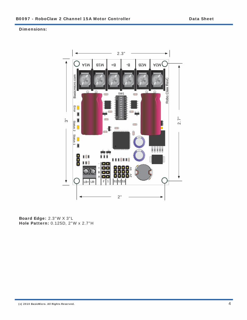
Dimensions:
Board Edge: 2.3”W X 3”LHole Pattern: 0.125D, 2”W x 2.7”H
2.3”
3”
2”
2.7”
SW1
Status 2
Status 1
Error
Bas
icm
icro
.com
ON
CTS
12
34
56
78
910
Rob
o C
law
Rev
C
M2A M2B B- B+ M1B M1A
LB+ LB- S1 S2 S32 1
-+BA 2V
5
V
(c) 2010 BasicMicro. All Rights Reserved.
B0097 - RoboClaw 2 Channel 15A Motor Controller Data Sheet
5
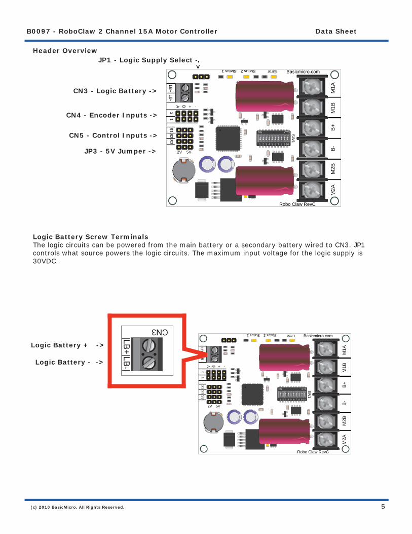
Header Overview
Logic Battery Screw TerminalsThe logic circuits can be powered from the main battery or a secondary battery wired to CN3. JP1 controls what source powers the logic circuits. The maximum input voltage for the logic supply is 30VDC.
CN3 - Logic Battery ->
CN4 - Encoder Inputs ->
CN5 - Control Inputs ->
JP3 - 5V Jumper ->
JP1 - Logic Supply Select -
<-
Logic Battery + ->
Logic Battery - ->
CN3
|LB+|LB
-|
SW
1
Status 2Status 1 Error Basicmicro.com
ON CTS
1 2 3 4 5 6 7 8 9 10
Robo Claw RevC
M2A
M2B
B-
B+
M1B
M1A
LB+
LB-
S1
S2
S3
21
-+BA
2V 5V
SW
1
Status 2Status 1 Error Basicmicro.com
ON CTS
1 2 3 4 5 6 7 8 9 10
Robo Claw RevC
M2A
M2B
B-
B+
M1B
M1A
LB+
LB-
S1
S2
S3
21
-+BA
2V 5V

(c) 2010 BasicMicro. All Rights Reserved.
B0097 - RoboClaw 2 Channel 15A Motor Controller Data Sheet
6
SW1
Status 2
Status 1
Error
Bas
icm
icro
.com
ON
CTS
12
34
56
78
910
Rob
o C
law
Rev
C
M2A M2B B- B+ M1B M1A
LB+ LB- S1 S2 S32 1
-+BA 2V
5
V
Encoder InputsThis header is setup for dual quadrature encoders. A and B are the inputs from the encoders. The header also supplies 5VDC to power the encoders. When connecting the encoder make sure the leading channel for the direction of rotation is connected to A. If one encoder is backwards to the other you will have one internal counter counting up and the other counting down. Which will affect the operation of Robo Claw. Refer to the data sheet of the encoder you are using for channel direction.
Control InputsS1, S2 and S3 are setup for standard servo style headers GND, +5V and I/O. S1 and S2 are the control inputs for serial, analog and RC modes. S3 used as a fl ip switch input when in RC or Analog modes. In serial mode S3 becomes a emergency stop.
SW1
Status 2
Status 1
Error
Bas
icm
icro
.com
ON
CTS
12
34
56
78
910
Rob
o C
law
Rev
C
M2A M2B B- B+ M1B M1A
LB+ LB- S1 S2 S32 1
-+BA 2V
5
VEncoder 2 -<
-
<-
- Encoder 1
Encoder VCC ->
Encoder VSS ->
Encoder Channel A ->
Encoder Channel B ->
I/O ->
VCC ->
GND ->
CN
42 | 1
-+BA
CN5
S1S2 S3
(c) 2010 BasicMicro. All Rights Reserved.
B0097 - RoboClaw 2 Channel 15A Motor Controller Data Sheet
7
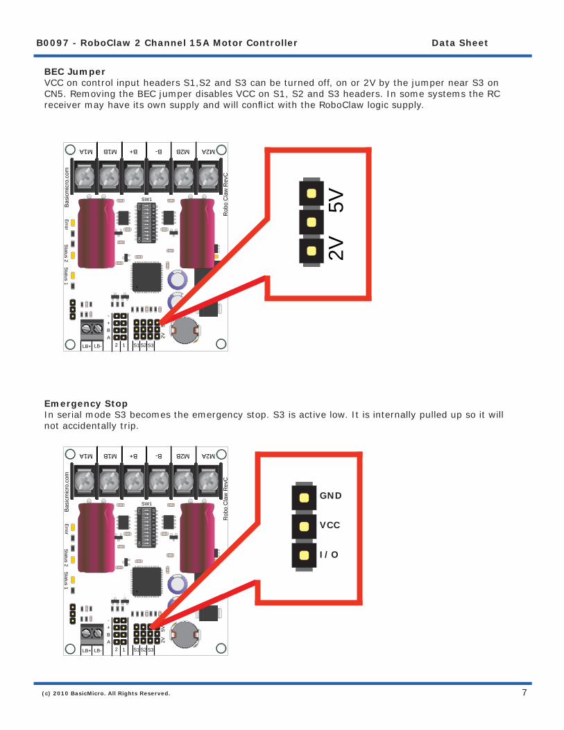
BEC JumperVCC on control input headers S1,S2 and S3 can be turned off, on or 2V by the jumper near S3 on CN5. Removing the BEC jumper disables VCC on S1, S2 and S3 headers. In some systems the RC receiver may have its own supply and will confl ict with the RoboClaw logic supply.
Emergency StopIn serial mode S3 becomes the emergency stop. S3 is active low. It is internally pulled up so it will not accidentally trip.
SW1
Status 2
Status 1
Error
Bas
icm
icro
.com
ON
CTS
12
34
56
78
910
Rob
o C
law
Rev
C
M2A M2B B- B+ M1B M1A
LB+ LB- S1 S2 S32 1
-+BA 2V
5
V
SW1S
tatus 2S
tatus 1E
rror
Bas
icm
icro
.com
ON
CTS
12
34
56
78
910
Rob
o C
law
Rev
C
M2A M2B B- B+ M1B M1A
LB+ LB- S1 S2 S32 1
-+BA 2V
5
V
2V
5V
GND
VCC
I/O

(c) 2010 BasicMicro. All Rights Reserved.
B0097 - RoboClaw 2 Channel 15A Motor Controller Data Sheet
8
Logic Supply SelectThe RoboClaw logic requires 5VDC which is provided from the on board regulator. The regulator source input is set with the logic supply jumper. Set to LB for a separate logic battery or MB for the main battery as the source.
SW1
Status 2
Status 1
Error
Bas
icm
icro
.com
ON
CTS
12
34
56
78
910
Rob
o C
law
Rev
C
M2A M2B B- B+ M1B M1A
LB+ LB- S1 S2 S32 1
-+BA 2V
5
V
LB
MB
LB
MB

(c) 2010 BasicMicro. All Rights Reserved.
B0097 - RoboClaw 2 Channel 15A Motor Controller Data Sheet
9
Main Battery Screw TerminalsThe main battery connections are marked with a B- and B+ on the main screw terminal. B+ is the positive side of the battery typically marked with a red wire. The B- is the negative side of the battery and typically marked with a black wire. When connecting the main battery its a good practice to use a switch to turn the main power on and off. When placing a switch in between the RoboClaw and main battery you must use a switch with the proper current rating. Since the RoboClaw can draw up to 30Amps peak you should use a switch rated for at least 40Amps. The main battery can be 6V to 30V DC.
Motor Screw TerminalsThe motor screw terminals are marked with M1A / M1B for channel 1 and M2A / M2B for channel 2. There is no specifi c polarities for the motors. However if you want both motors turning in the same direction on a 4 wheeled robot you need to reverse one of the motors as shown below:
DC Motor 1
DC Motor 1
12VDC Battery
Power Switch
M2A
M2B
B-
B+
M1B
M1A
M2A
M2B
B-
B+
M1B
M1A
DC Motor 2
(c) 2010 BasicMicro. All Rights Reserved.
B0097 - RoboClaw 2 Channel 15A Motor Controller Data Sheet
10
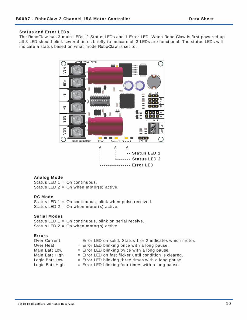
Status and Error LEDsThe RoboClaw has 3 main LEDs. 2 Status LEDs and 1 Error LED. When Robo Claw is fi rst powered up all 3 LED should blink several times briefl y to indicate all 3 LEDs are functional. The status LEDs will indicate a status based on what mode RoboClaw is set to.
Analog Mode Status LED 1 = On continuous. Status LED 2 = On when motor(s) active.
RC Mode Status LED 1 = On continuous, blink when pulse received. Status LED 2 = On when motor(s) active.
Serial Modes Status LED 1 = On continuous, blink on serial receive. Status LED 2 = On when motor(s) active.
Errors Over Current = Error LED on solid. Status 1 or 2 indicates which motor. Over Heat = Error LED blinking once with a long pause. Main Batt Low = Error LED blinking twice with a long pause. Main Batt High = Error LED on fast fl icker until condition is cleared. Logic Batt Low = Error LED blinking three times with a long pause. Logic Batt High = Error LED blinking four times with a long pause.
---------------- Error LED-------- Status LED 2
-- Status LED 1
<-----
<--------
<--
SW
1
Status 2 Status 1Error
Basicmicro.com
ONCTS
12345678910
Robo Claw RevC
M2A M
2B B
- B+ M
1B M
1A LB+
LB-
S1
S2
S3
21
- + B A
2V 5V
LB MB

(c) 2010 BasicMicro. All Rights Reserved.
B0097 - RoboClaw 2 Channel 15A Motor Controller Data Sheet
11
SW
1
Status 2Status 1 Error Basicmicro.com
ON CTS
1 2 3 4 5 6 7 8 9 10
Robo Claw RevC
M2A
M2B
B-
B+
M1B
M1A
LB+
LB-
S1
S2
S3
21
-+BA
2V 5V
LB MB
DIP Switch OverviewThe dip switch on RoboClaw is used to set its operating modes and the many options. The switch is marked with an ON label at its top. The switches are also labeled from left to right starting with switch 1 and ending with switch 10. When a dip switch is moved toward the label ON it is considered ON. When the switch is facing away from the ON label it is considered off. Be careful to ensure the switch is not fl oating in between and is fi rmly OFF or ON. See illustration below. The red switch (SW1) is in the ON position. The grey colored switches are in the OFF position.
ON CTS
1 2 3 4 5 6 7 8 9 10

(c) 2010 BasicMicro. All Rights Reserved.
B0097 - RoboClaw 2 Channel 15A Motor Controller Data Sheet
12
Low Voltage CutoffRoboClaw has a built in low voltage protection. This has two main purposed. To protect RoboClaw from running erratically when the main battery level gets to low and protect a Lithium battery from being damaged.
Voltage SW8 SW9 SW10Not Monitored OFF OFF OFFLead Acid - Auto ON OFF OFF2- Cell (6V Cutoff) OFF ON OFF3- Cell (9V Cutoff) ON ON OFF4- Cell (12V Cutoff) OFF OFF ON5- Cell (15V Cutoff) ON OFF ON6- Cell (18V Cutoff) OFF ON ON7- Cell (21V Cutoff) ON ON ON

(c) 2010 BasicMicro. All Rights Reserved.
B0097 - RoboClaw 2 Channel 15A Motor Controller Data Sheet
13
RoboClaw ModesThere are 4 modes. Each with a specifi c way to control RoboClaw. The following list explain each mode and the ideal application.
Mode 1 - RC InputWith RC input mode RoboClaw can be controlled from any hobby RC radio system. RC input mode also allows low powered microcontroller such as a Basic Stamp or Nano to control RoboClaw. RoboClaw expects servo pulse inputs to control the direction and speed. Very similar to how a regular servo is controlled. RC mode can not use encoders.
Mode 2 - AnalogAnalog mode uses an analog signal from 0V to 5V to control the speed and direction of each motor. RoboClaw can be controlled using a potentiometer or fi ltered PWM from a microcontroller. Analog mode is ideal for interfacing RoboClaw joystick positioning systems or other non microcontroller interfacing hardware. Analog mode can not use encoders.
Mode 3 - Simple SerialIn simple serial mode RoboClaw expects TTL level RS-232 serial data to control direction and speed of each motor. Simple serial is typically used to control RoboClaw from a microcontroller or PC. If using a PC a MAX232 type circuit must be used since RoboClaw only works with TTL level input. Simple serial includes a slave select mode which allows multiple RoboClaws to be controlled from a signal RS-232 port (PC or microcontroller). Simple serial is a one way format, RoboClaw only receives data.
Mode 4 - Packet SerialIn packet serial mode RoboClaw expects TTL level RS-232 serial data to control direction and speed of each motor. Packet serial is typically used to control RoboClaw from a microcontroller or PC. If using a PC a MAX232 type circuit must be used since RoboClaw only works with TTL level input. In packet serial mode each RoboClaw is assigned an address using the dip switches. There are 8 addresses available. This means up to 8 RoboClaws can be on the same serial port. When using the quadrature decoding feature of RoboClaw packet serial is required since it is a two way communications format. This allows RoboClaw to transmit information about the encoders position and speed.
(c) 2010 BasicMicro. All Rights Reserved.
B0097 - RoboClaw 2 Channel 15A Motor Controller Data Sheet
14
RC Input

(c) 2010 BasicMicro. All Rights Reserved.
B0097 - RoboClaw 2 Channel 15A Motor Controller Data Sheet
15
Mode 1 - RC InputFor RC mode set SW1 = ON. RC mode is typically used when controlling RoboClaw from a hobby RC radio. This mode can also be used to simplify driving RoboClaw from a microcontroller using servo pulses. There are 4 options in RC Input mode. These options are set with SW4, SW5, SW6 and SW7.
Switch 4 - Mixing Mode SW4 = ON: Turns mixing mode ON. S1 controls forward and reverse. S2 controls steering. Control will be like a car. SW4 = OFF: Turns mixing mode OFF. S1 controls motor 1 speed and direction. S2 controls motor 2 speed and direction. Control will be like a tank.
Switch 5 - Exponential Mode SW5 = ON: Turns exponential mode ON. Exponential response softens the center control position. This mode is ideal with tank style robots. SW5 = OFF: Turns exponential mode OFF. Motor response will be linear and directly proportional to the control input. Ideal for 4 wheel style robots.
ON CTS
1 2 3 4 5 6 7 8 9 10
ON CTS
1 2 3 4 5 6 7 8 9 10
ON CTS
1 2 3 4 5 6 7 8 9 10
(c) 2010 BasicMicro. All Rights Reserved.
B0097 - RoboClaw 2 Channel 15A Motor Controller Data Sheet
16
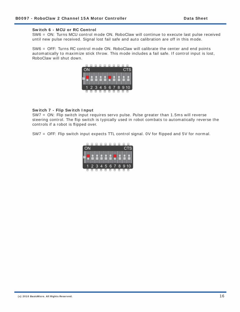
Switch 6 - MCU or RC Control SW6 = ON: Turns MCU control mode ON. RoboClaw will continue to execute last pulse received until new pulse received. Signal lost fail safe and auto calibration are off in this mode. SW6 = OFF: Turns RC control mode ON. RoboClaw will calibrate the center and end points automatically to maximize stick throw. This mode includes a fail safe. If control input is lost, RoboClaw will shut down.
Switch 7 - Flip Switch Input SW7 = ON: Flip switch input requires servo pulse. Pulse greater than 1.5ms will reverse steering control. The fl ip switch is typically used in robot combats to automatically reverse the controls if a robot is fl ipped over. SW7 = OFF: Flip switch input expects TTL control signal. 0V for fl ipped and 5V for normal.
ON CTS
1 2 3 4 5 6 7 8 9 10
ON CTS
1 2 3 4 5 6 7 8 9 10

(c) 2010 BasicMicro. All Rights Reserved.
B0097 - RoboClaw 2 Channel 15A Motor Controller Data Sheet
17
Servo Pulse RangesThe RoboClaw expects RC servo pulses on S1 and S2 to drive the motors when the dip switches are set for RC mode. The center points are calibrated at start up. 1000us is the default for full reverse and 2000us is the default for full forward. The RoboClaw will auto calibrate these ranges on the fl y. If a pulse smaller than 1000us or larger than 2000us is detected the new pulses will be set as the new range.
Pulse Function1000us Full Reverse2000us Full Forward

(c) 2010 BasicMicro. All Rights Reserved.
B0097 - RoboClaw 2 Channel 15A Motor Controller Data Sheet
18
RC Wiring ExampleConnect the RoboClaw as shown below. Set switches SW1 and SW4 to ON. Make sure you center the control sticks and turn the radio on fi rst, then the receiver, then RoboClaw. It will take RoboClaw about 1 second to calibrate the neutral position.
DC Motor 1 DC Motor 2
Power Switch
SW1
Sta
tus
2S
tatu
s 1
Err
or
Basicm
icro.com
ON
CTS
12
34
56
78
910
Robo C
law R
evC
M2A M2B B- B+ M1B M1A
LB+LB-S1S2S3 21
-+BA2V
5V
LB M
B
BAT
-
THRAILEELERUDGERAUX
+ ~
SPEKTRUM
AR
6000Battery
Battery
Install Jumper on MB (Main Battery)
<-
<-
Remove BEC Jumper
(c) 2010 BasicMicro. All Rights Reserved.
B0097 - RoboClaw 2 Channel 15A Motor Controller Data Sheet
19
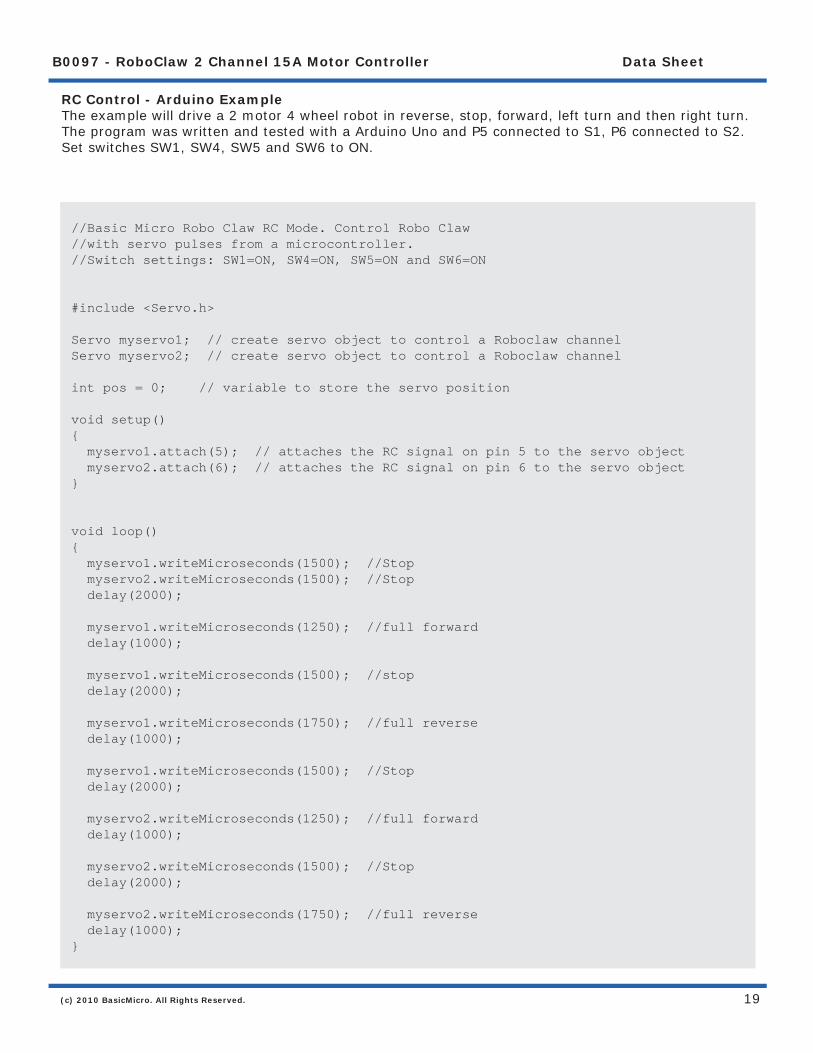
RC Control - Arduino ExampleThe example will drive a 2 motor 4 wheel robot in reverse, stop, forward, left turn and then right turn. The program was written and tested with a Arduino Uno and P5 connected to S1, P6 connected to S2. Set switches SW1, SW4, SW5 and SW6 to ON.
//Basic Micro Robo Claw RC Mode. Control Robo Claw //with servo pulses from a microcontroller. //Switch settings: SW1=ON, SW4=ON, SW5=ON and SW6=ON
#include <Servo.h> Servo myservo1; // create servo object to control a Roboclaw channelServo myservo2; // create servo object to control a Roboclaw channel int pos = 0; // variable to store the servo position void setup() { myservo1.attach(5); // attaches the RC signal on pin 5 to the servo object myservo2.attach(6); // attaches the RC signal on pin 6 to the servo object } void loop() { myservo1.writeMicroseconds(1500); //Stop myservo2.writeMicroseconds(1500); //Stop delay(2000);
myservo1.writeMicroseconds(1250); //full forward delay(1000);
myservo1.writeMicroseconds(1500); //stop delay(2000);
myservo1.writeMicroseconds(1750); //full reverse delay(1000);
myservo1.writeMicroseconds(1500); //Stop delay(2000);
myservo2.writeMicroseconds(1250); //full forward delay(1000);
myservo2.writeMicroseconds(1500); //Stop delay(2000);
myservo2.writeMicroseconds(1750); //full reverse delay(1000);}

(c) 2010 BasicMicro. All Rights Reserved.
B0097 - RoboClaw 2 Channel 15A Motor Controller Data Sheet
20
RC Control - BasicATOM Pro ExampleThe example will drive a 2 motor 4 wheel robot in reverse, stop, forward, left turn and then right turn. The program was written and tested with a BasicATOM Pro and P0 connected to S1, P1 connected to S2. Set switches SW1, SW4, SW5 and SW6 to ON.
;Basic Micro Robo Claw RC Mode. Control Robo Claw ;with servo pulses from a microcontroller. ;Switch settings: SW1=ON, SW4=ON, SW5=ON and SW6=ON
Main pulsout P15,(1500*2) ; stop pulsout P14,(1500*2) ; stop pause 2000
pulsout P15,(500*2) ; full backward pause 1000 pulsout P15,(1500*2) ; stop pause 2000 pulsout P15,(2500*2) ; full forward pause 1000
pulsout P15,(1500*2) ; stop pause 2000 pulsout P14,(500*2) ; left turn pause 1000 pulsout P14,(1500*2) ; stop pause 2000 pulsout P14,(2500*2) ; right turn pause 1000 goto main
(c) 2010 BasicMicro. All Rights Reserved.
B0097 - RoboClaw 2 Channel 15A Motor Controller Data Sheet
21
Analog Input

(c) 2010 BasicMicro. All Rights Reserved.
B0097 - RoboClaw 2 Channel 15A Motor Controller Data Sheet
22
Mode 2 - Analog InputFor Analog mode set SW1,SW2 and SW3 = OFF. In this mode S1 and S2 are set as analog inputs. Voltages of 0V = Full reverse, 1V = Stop and 2V = Full forward. You can use linear potentiometers of 1K to 100K to control RoboClaw. Or you can use a PWM signal to control RoboClaw in analog mode. If using a PWM signal to control RoboClaw you will need a simple fi lter circuit to clean up the pulse. If using a potentiometer set the BEC header to 2V.
Switch 4 - Mixing Mode SW4 = ON: Turns mixing mode ON. One channel input to control forward and reverse. Second channel input for steering control. Control will be like a car. SW4 = OFF: Turns mixing mode OFF. One channel controls one motor speed and direction. Second channel controls the other motor speed and direction. Control will be like a tank.
Switch 5 - Exponential Mode SW5 = ON: Turns exponential mode ON. Exponential response softens the center control position. This mode is ideal with tank style robots. SW5 = OFF: Turns exponential mode OFF. Motor response will be linear and directly proportional to the control input. Ideal for 4 wheel style robots.
ON CTS
1 2 3 4 5 6 7 8 9 10
ON CTS
1 2 3 4 5 6 7 8 9 10
ON CTS
1 2 3 4 5 6 7 8 9 10

(c) 2010 BasicMicro. All Rights Reserved.
B0097 - RoboClaw 2 Channel 15A Motor Controller Data Sheet
23
Switch 7 - Flip Switch SW7 = ON: Turns the fl ip switch input S3 on. The fl ip switch signal is a TTL driven signal. 0V is active and 5V is not active. When the fl ip switch signal is active all inputs to RoboClaw are reversed. SW7 = OFF: Turns fl ip switch input S3 off.
ON CTS
1 2 3 4 5 6 7 8 9 10

(c) 2010 BasicMicro. All Rights Reserved.
B0097 - RoboClaw 2 Channel 15A Motor Controller Data Sheet
24
Analog Wiring ExampleConnect the RoboClaw as shown below using two potentiometers. Install BEC 2V jumper and set switch SW4 to ON (Mixing Mode). You can also use the wire example with SW4 OFF. Center the potentiometers before applying power or the attached motors will start moving. S1 potentiometer in mix mode (SW4) will control forward and reverse. S2 potentiometer in mix mode (SW4) will control turning (LEFT / RIGHT).
SW1
Sta
tus
2S
tatu
s 1
Err
or
Basicm
icro.com
ON
CTS
12
34
56
78
910
Robo C
law R
evC
M2A M2B B- B+ M1B M1A
LB+LB-S1S2S3 21
-+BA2V
5V
LB M
B
DC Motor 1 DC Motor 2
Power Switch
12VDC Battery
10
K1
0K
S1 Potentiometer
S2 Potentiometer
Install Jumper on MB (Main Battery)
<-
(c) 2010 BasicMicro. All Rights Reserved.
B0097 - RoboClaw 2 Channel 15A Motor Controller Data Sheet
25
Simple Serial
(c) 2010 BasicMicro. All Rights Reserved.
B0097 - RoboClaw 2 Channel 15A Motor Controller Data Sheet
26
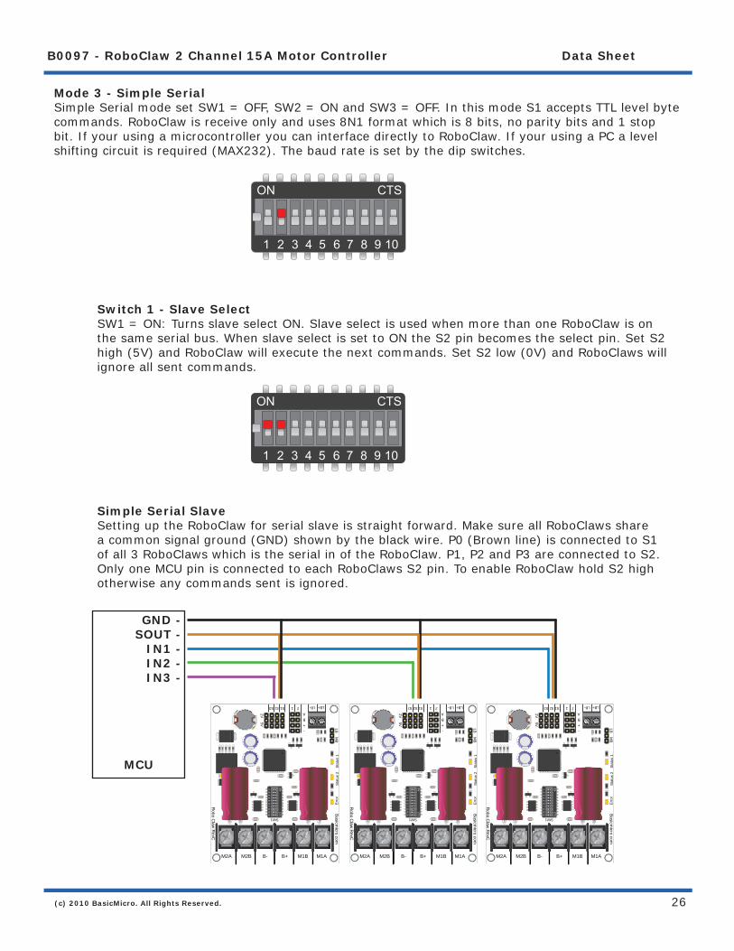
Mode 3 - Simple SerialSimple Serial mode set SW1 = OFF, SW2 = ON and SW3 = OFF. In this mode S1 accepts TTL level byte commands. RoboClaw is receive only and uses 8N1 format which is 8 bits, no parity bits and 1 stop bit. If your using a microcontroller you can interface directly to RoboClaw. If your using a PC a level shifting circuit is required (MAX232). The baud rate is set by the dip switches.
Switch 1 - Slave Select SW1 = ON: Turns slave select ON. Slave select is used when more than one RoboClaw is on the same serial bus. When slave select is set to ON the S2 pin becomes the select pin. Set S2 high (5V) and RoboClaw will execute the next commands. Set S2 low (0V) and RoboClaws will ignore all sent commands.
Simple Serial Slave Setting up the RoboClaw for serial slave is straight forward. Make sure all RoboClaws share a common signal ground (GND) shown by the black wire. P0 (Brown line) is connected to S1 of all 3 RoboClaws which is the serial in of the RoboClaw. P1, P2 and P3 are connected to S2. Only one MCU pin is connected to each RoboClaws S2 pin. To enable RoboClaw hold S2 high otherwise any commands sent is ignored.
ON CTS
1 2 3 4 5 6 7 8 9 10
ON CTS
1 2 3 4 5 6 7 8 9 10
MCU
GND -SOUT -
IN1 -IN2 -IN3 -
SW1
Stat
us 2
Stat
us 1
Erro
r
Basicmicro.com
ON
CTS
12
34
56
78
910
Robo C
law R
evC
M2A M2B B- B+ M1B M1A
LB+LB-S1S2S3 21
-+BA2V 5V
LB MB
SW1
Stat
us 2
Stat
us 1
Erro
r
Basicmicro.com
ON
CTS
12
34
56
78
910
Robo C
law R
evC
M2A M2B B- B+ M1B M1A
LB+LB-S1S2S3 21
-+BA2V 5V
LB MB
SW1
Stat
us 2
Stat
us 1
Erro
r
Basicmicro.com
ON
CTS
12
34
56
78
910
Robo C
law R
evC
M2A M2B B- B+ M1B M1A
LB+LB-S1S2S3 21
-+BA2V 5V
LB MB

(c) 2010 BasicMicro. All Rights Reserved.
B0097 - RoboClaw 2 Channel 15A Motor Controller Data Sheet
27
Baud RateRoboClaw supports 4 baud rates in serial mode. The baud rate is selected by setting switch 4 and 5.
Baud Rate SW4 SW52400 OFF OFF9600 ON OFF19200 OFF ON38400 ON ON
2400 Baud 9600 Baud
19200 Baud 38400 Baud
Simple Serial Command SyntaxThe RoboClaw simple serial is setup to control both motors with one byte sized command character. Since a byte can be anything from 0 to 255 the control of each motor is split. 1 to 127 controls channel 1 and 128 to 255 controls channel 2. Command character 0 will shut down both channels. Any characters in between will control speed, direction of each channel.
Character Function0 Shuts Down Channel 1 and 21 Channel 1 - Full Reverse64 Channel 1 - Stop127 Channel 1 - Full Forward128 Channel 2 - Full Reverse192 Channel 2 - Stop255 Channel 2 - Full Forward
ON CTS
1 2 3 4 5 6 7 8 9 10
ON CTS
1 2 3 4 5 6 7 8 9 10
ON CTS
1 2 3 4 5 6 7 8 9 10
ON CTS
1 2 3 4 5 6 7 8 9 10
(c) 2010 BasicMicro. All Rights Reserved.
B0097 - RoboClaw 2 Channel 15A Motor Controller Data Sheet
28
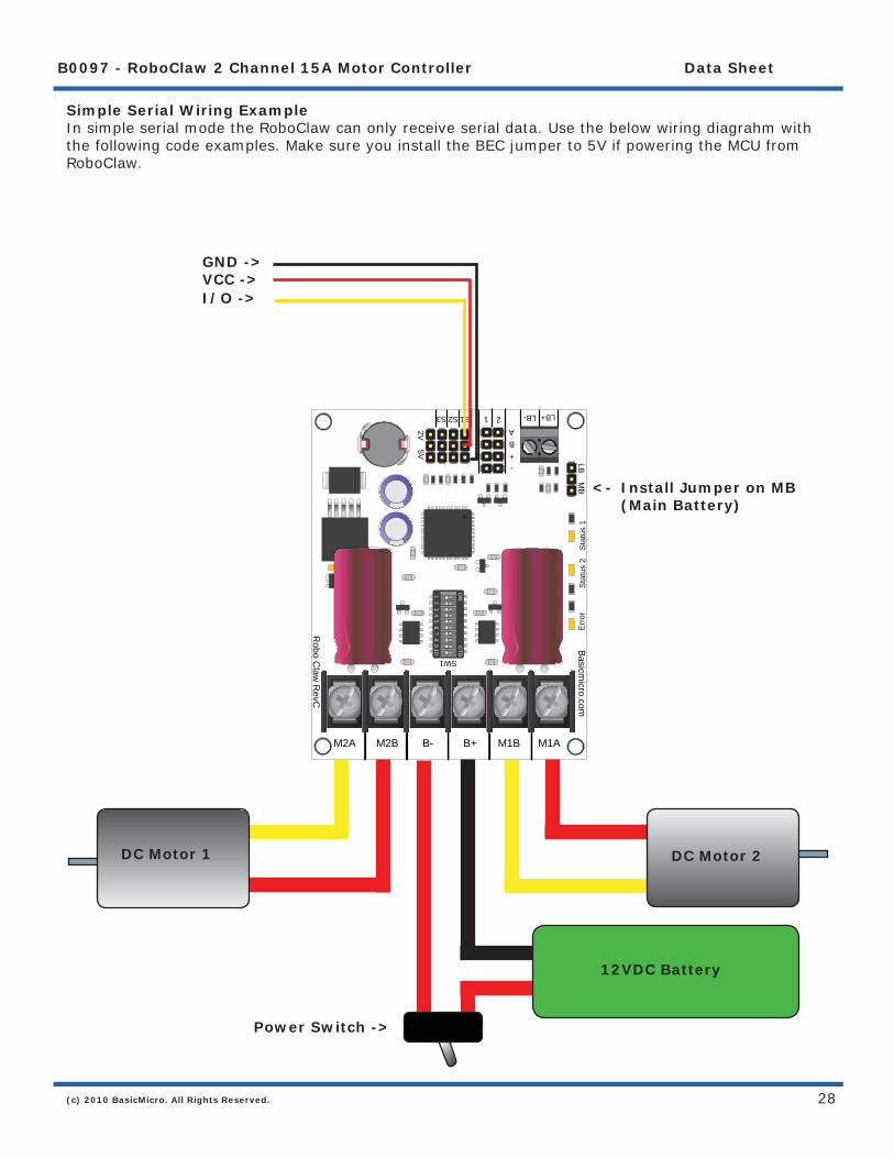
Simple Serial Wiring ExampleIn simple serial mode the RoboClaw can only receive serial data. Use the below wiring diagrahm with the following code examples. Make sure you install the BEC jumper to 5V if powering the MCU from RoboClaw.
SW1
Sta
tus
2S
tatu
s 1
Err
or
Basicm
icro.com
ON
CTS
12
34
56
78
910
Robo C
law R
evC
M2A M2B B- B+ M1B M1ALB+LB-S1S2S3 21
-+BA2V
5V
LB M
B
DC Motor 1 DC Motor 2
Power Switch ->
12VDC Battery
VCC ->GND ->
I/O ->
Install Jumper on MB (Main Battery)
<-

(c) 2010 BasicMicro. All Rights Reserved.
B0097 - RoboClaw 2 Channel 15A Motor Controller Data Sheet
29
Simple Serial - Arduino ExampleThe following example will start both channels in reverse, stop, then full speed forward. The program was written and tested with a Arduino Uno and Pin 5 connected to S1. Set switch SW2 and SW5 to ON.
//Basic Micro Robo Claw Simple Serial Test//Switch settings: SW2=ON and SW5=ON//Make sure Arduino and Robo Claw share common GND!
#include “BMSerial.h”
BMSerial mySerial(5,6);
void setup() { mySerial.begin(19200);}
void loop() { mySerial.write(1); mySerial.write(-1); delay(2000); mySerial.write(127); mySerial.write(-127); delay(2000);}
ON CTS
1 2 3 4 5 6 7 8 9 10

(c) 2010 BasicMicro. All Rights Reserved.
B0097 - RoboClaw 2 Channel 15A Motor Controller Data Sheet
30
Simple Serial - BasicATOM Pro ExampleThe following example will start both channels in reverse, stop, then full speed forward. The program was written and tested with a BasicATOM Pro and P0 connected to S1. Set switch SW2 and SW5 to ON.
;Basic Micro Robo Claw Simple Serial Test;Switch settings: SW2=ON and SW5=ON;Make sure BAP and Robo Claw share common GND!
Main Serout P15, i19200, [0] ;Full stop both channels Pause 500 Serout P15, i19200, [96,224] ;Foward slowly Pause 3000 Serout P15, i19200, [127,255] ;Foward fast Pause 3000
Serout P15, i19200, [64,192] ;Full stop both channels Pause 500 Serout P15, i19200, [32,160] ;Reverse slowly Pause 3000 Serout P15, i19200, [1,128] ;Reverse fast Pause 3000 Goto Main
ON CTS
1 2 3 4 5 6 7 8 9 10

(c) 2010 BasicMicro. All Rights Reserved.
B0097 - RoboClaw 2 Channel 15A Motor Controller Data Sheet
31
Packet Serial
(c) 2010 BasicMicro. All Rights Reserved.
B0097 - RoboClaw 2 Channel 15A Motor Controller Data Sheet
32
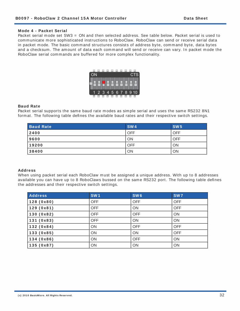
Mode 4 - Packet SerialPacket serial mode set SW3 = ON and then selected address. See table below. Packet serial is used to communicate more sophisticated instructions to RoboClaw. RoboClaw can send or receive serial data in packet mode. The basic command structures consists of address byte, command byte, data bytes and a checksum. The amount of data each command will send or receive can vary. In packet mode the RoboClaw serial commands are buffered for more complex functionality.
Baud RatePacket serial supports the same baud rate modes as simple serial and uses the same RS232 8N1 format. The following table defi nes the available baud rates and their respective switch settings.
Baud Rate SW4 SW52400 OFF OFF9600 ON OFF19200 OFF ON38400 ON ON
AddressWhen using packet serial each RoboClaw must be assigned a unique address. With up to 8 addresses available you can have up to 8 RoboClaws bussed on the same RS232 port. The following table defi nes the addresses and their respective switch settings.
Address SW1 SW6 SW7128 (0x80) OFF OFF OFF129 (0x81) OFF ON OFF130 (0x82) OFF OFF ON131 (0x83) OFF ON ON132 (0x84) ON OFF OFF133 (0x85) ON ON OFF134 (0x86) ON OFF ON135 (0x87) ON ON ON
ON CTS
1 2 3 4 5 6 7 8 9 10

(c) 2010 BasicMicro. All Rights Reserved.
B0097 - RoboClaw 2 Channel 15A Motor Controller Data Sheet
33
Checksum CalculationAll packet serial commands use a 7 bit checksum to prevent corrupt commands from being executed. Since the RoboClaw expects a 7bit value the 8th bit is masked. The checksum is calculated as follows:
Address + Command + Data = Checksum
To mask the 8th bit you use can a simple math expression called AND as shown below:
Serout P15, i19200, [128, 0, 127, (255 & 0X7F)]
The hexadecimal value 0X7F is used to mask the 8th bit. You can also use a binary value of 01111111 as shown below:
Serout P15, i19200, [128, 0, 127, (255 & %01111111)]

(c) 2010 BasicMicro. All Rights Reserved.
B0097 - RoboClaw 2 Channel 15A Motor Controller Data Sheet
34
Commands 0 - 7 Standard CommandsThe following commands are the standard set of commands used with packet mode. The command syntax is the same for commands 0 to 7:
Address, Command, ByteValue, Checksum
0 - Drive Forward M1Drive motor 1 forward. Valid data range is 0 - 127. A value of 127 = full speed forward, 64 = about half speed forward and 0 = full stop. Example with RoboClaw address set to 128:
Serout P15, i19200, [128, 0, 127, (255 & 0X7F)] ;M1 full speed forward
1 - Drive Backwards M1 Drive motor 1 backwards. Valid data range is 0 - 127. A value of 127 full speed backwards, 64 = about half speed backward and 0 = full stop. Example with RoboClaw address set to 128:
Serout P15, i19200, [128, 1, 127, (256 & 0X7F)] ;M1 full speed forward
2 - Set Minimum Main Voltage Sets main battery (B- / B+) minimum voltage level. If the battery voltages drops below the set voltage level RoboClaw will shut down. The value is cleared at start up and must set after each power up. The voltage is set in .2 volt increments. A value of 0 sets the minimum value allowed which is 6V. The valid data range is 0 - 120 (6V - 30V). The formula for calculating the voltage is: (Desired Volts - 6) x 5 = Value. Examples of valid values are 6V = 0, 8V = 10 and 11V = 25. Example with RoboClaw address set to 128:
Serout P15, i19200, [128, 2, 25, (165 & 0X7F)]
3 - Set Maximum Main VoltageSets main battery (B- / B+) maximum voltage level. The valid data range is 0 - 154 (0V - 30V). If you are using a battery of any type you can ignore this setting. During regenerative breaking a back voltage is applied to charge the battery. When using an ATX type power supply if it senses anything over 16V it will shut down. By setting the maximum voltage level, RoboClaw before exceeding it will go into hard breaking mode until the voltage drops below the maximum value set. The formula for calculating the voltage is: Desired Volts x 5.12 = Value. Examples of valid values are 12V = 62, 16V = 82 and 24V = 123. Example with RoboClaw address set to 128:
Serout P15, i19200, [128, 3, 82, (213 & 0X7F)]
4 - Drive Forward M2Drive motor 2 forward. Valid data range is 0 - 127. A value of 127 full speed forward, 64 = about half speed forward and 0 = full stop. Example with RoboClaw address set to 128:
Serout P15, i19200, [128, 4, 127, (259 & 0X7F)] ;M2 full speed forward

(c) 2010 BasicMicro. All Rights Reserved.
B0097 - RoboClaw 2 Channel 15A Motor Controller Data Sheet
35
5 - Drive Backwards M2 Drive motor 2 backwards. Valid data range is 0 - 127. A value of 127 full speed backwards, 64 = about half speed backward and 0 = full stop. Example with RoboClaw address set to 128:
Serout P15, i19200, [128, 5, 127, (260 & 0X7F)] ;M2 full speed forward
6 - Drive M1 (7 Bit) Drive motor 1 forward and reverse. Valid data range is 0 - 127. A value of 0 = full speed reverse, 64 = stop and 127 = full speed forward. Example with RoboClaw address set to 128:
Serout P15, i19200, [128, 6, 96, (230 & 0X7F)] ;M1 half speed forward
7 - Drive M2 (7 Bit) Drive motor 2 forward and reverse. Valid data range is 0 - 127. A value of 0 = full speed reverse, 64 = stop and 127 = full speed forward. Example with RoboClaw address set to 128:
Serout P15, i19200, [128, 7, 32, (167 & 0X7F)] ;M2 half speed reverse

(c) 2010 BasicMicro. All Rights Reserved.
B0097 - RoboClaw 2 Channel 15A Motor Controller Data Sheet
36
Commands 8 - 13 Mix Mode CommandsThe following commands are mix mode commands and used to control speed and turn. Before a command is executed valid drive and turn data is required. You only need to send both data packets once. After receiving both valid drive and turn data RoboClaw will begin to operate. At this point you only need to update turn or drive data.
8 - Drive ForwardDrive forward in mix mode. Valid data range is 0 - 127. A value of 0 = full stop and 127 = full forward. Example with RoboClaw address set to 128:
Serout P15, i19200, [128, 8, 127, (263 & 0x7F)] ;full speed forward
9 - Drive BackwardsDrive backwards in mix mode. Valid data range is 0 - 127. A value of 0 = full stop and 127 = full reverse. Example with RoboClaw address set to 128:
Serout P15, i19200, [128, 9, 127, (264 & 0x7F)] ;full speed reverse
10 - Turn rightTurn right in mix mode. Valid data range is 0 - 127. A value of 0 = stop turn and 127 = full speed turn. Example with RoboClaw address set to 128:
Serout P15, i19200, [128, 10, 127, (265 & 0x7F1)] ;full speed right turn
11 - Turn leftTurn left in mix mode. Valid data range is 0 - 127. A value of 0 = stop turn and 127 = full speed turn. Example with RoboClaw address set to 128:
Serout P15, i19200, [128, 11, 127, (266 & 0x7F)] ;full speed left turn
12 - Drive Forward or Backward (7 Bit)Drive forward or backwards. Valid data range is 0 - 127. A value of 0 = full backward, 64 = stop and 127 = full forward. Example with RoboClaw address set to 128:
Serout P15, i19200, [128, 12, 96, (236 & 0x7F)] ;medium speed forward
13 - Turn Left or Right (7 Bit)Turn left or right. Valid data range is 0 - 127. A value of 0 = full left, 0 = stop turn and 127 = full right. Example with RoboClaw address set to 128:
Serout P15, i19200, [128, 13, 0, (141 & 0x7F)] ;full speed turn left

(c) 2010 BasicMicro. All Rights Reserved.
B0097 - RoboClaw 2 Channel 15A Motor Controller Data Sheet
37
Packet Serial WiringIn packet mode the RoboClaw can transmit and receive serial data. RoboClaw is transmitting return data a processor with a hardware serial port is required.
JP1
JP3
C20
JP2
R16 C19
C21
C5 C2
C22R28 R32
VD3
CN5
CN
4
R4
R3
R5
R6
CN
3
R2
R29
R25
C1
U2
U4
Y1
SW1
R15 VD2
Q14C9
R9
C14
R17
R13
C3
C4
R1
R2
R30
R7
R18
C13
Reset
Pow
er Sel
S1S2S3+5V
Sta
tus2
Sta
tus1
2 | 1
-+BA
Err
or
Rob
o C
law
M1A M1B B+ B- M2B M2A
Basicmicro.com (c) 2009
ON
CTS
12
34
56
78
910
DC Motor 1 DC Motor 2
Power Switch
12VDC Battery
VCC ->GND ->
S1 ->S2 ->

(c) 2010 BasicMicro. All Rights Reserved.
B0097 - RoboClaw 2 Channel 15A Motor Controller Data Sheet
38
Packet Serial - Arduino ExampleThe example will start the motor channels independently. Then start turns with mix mode commands. The program was written and tested with a Arduno Uno and P5 connected to S1. Set switch SW3 and SW5 to ON.
//Basic Micro Robo Claw Packet Serial Test Commands 0 to 13.//Switch settings: SW3=ON and SW5=ON.
#include “BMSerial.h”#include “RoboClaw.h”
#defi ne address 0x80
RoboClaw roboclaw(5,6);
void setup() { roboclaw.begin(19200);}
void loop() { roboclaw.ForwardM1(address,64); //Cmd 0 roboclaw.BackwardM2(address,64); //Cmd 5 delay(2000); roboclaw.BackwardM1(address,64); //Cmd 1 roboclaw.ForwardM2(address,64); //Cmd 6 delay(2000); roboclaw.ForwardBackwardM1(address,96); //Cmd 6 roboclaw.ForwardBackwardM2(address,32); //Cmd 7 delay(2000); roboclaw.ForwardBackwardM1(address,32); //Cmd 6 roboclaw.ForwardBackwardM2(address,96); //Cmd 7 delay(2000);
//stop motors roboclaw.ForwardBackwardM1(address,0); roboclaw.ForwardBackwardM2(address,0);
delay(10000);
roboclaw.ForwardMixed(address, 64); //Cmd 8 delay(2000); roboclaw.BackwardMixed(address, 64); //Cmd 9 delay(2000); roboclaw.TurnRightMixed(address, 64); //Cmd 10 delay(2000); roboclaw.TurnLeftMixed(address, 64); //Cmd 11 delay(2000); roboclaw.ForwardBackwardMixed(address, 32); //Cmd 12 delay(2000); roboclaw.ForwardBackwardMixed(address, 96); //Cmd 12 delay(2000); roboclaw.LeftRightMixed(address, 32); //Cmd 13 delay(2000); roboclaw.LeftRightMixed(address, 96); //Cmd 13 delay(2000);
//stop motors roboclaw.ForwardMixed(address, 0);
delay(10000);}

(c) 2010 BasicMicro. All Rights Reserved.
B0097 - RoboClaw 2 Channel 15A Motor Controller Data Sheet
39
Packet Serial - BasicATOM Pro ExampleThe example will start the motor channels independently. Then start turns with mix mode commands. The program was written and tested with a BasicATOM Pro and P15 connected to S1. Set switch SW3 and SW5 to ON.
;Basic Micro Robo Claw Packet Serial Test Commands 0 to 13. ;Switch settings: SW3=ON and SW5=ON.
Main Pause 2000 Serout P15, i19200, [128, 0, 127, (255 & 0x7F)];M1 full speed forward Serout P15, i19200, [128, 4, 127, (259 & 0x7F)];M2 full speed forward Pause 1000 Serout P15, i19200, [128, 0, 0, (128 & 0x7F)];M1 stop Serout P15, i19200, [128, 4, 0, (132 & 0x7F)];M2 stop Pause 1000 Serout P15, i19200, [128, 1, 127, (256 & 0x7F)];M1 full speed backwards Serout P15, i19200, [128, 5, 127, (260 & 0x7F)];M1 full speed backwards Pause 1000 Serout P15, i19200, [128, 0, 0, (128 & 0x7F)];M1 stop Serout P15, i19200, [128, 4, 0, (132 & 0x7F)];M2 stop Pause 1000 Serout P15, i19200, [128, 10, 127, (265 & 0x7F)];Mix mode right full speed Pause 1000 Serout P15, i19200, [128, 10, 0, (138 & 0x7F)];Mix mode stop Pause 1000 Serout P15, i19200, [128, 11, 127, (266 & 0x7F)];Mix mode left full speed Pause 1000 Serout P15, i19200, [128, 11, 0, (139 & 0x7F)];Mix mode stopGoto Main

(c) 2010 BasicMicro. All Rights Reserved.
B0097 - RoboClaw 2 Channel 15A Motor Controller Data Sheet
40
Battery and Version Information

(c) 2010 BasicMicro. All Rights Reserved.
B0097 - RoboClaw 2 Channel 15A Motor Controller Data Sheet
41
21 - Read Firmware VersionRead RoboClaw fi rmware version. Returns up to 32 bytes and is terminated by a null character. Command syntax:
Sent: [Address, CMD] Received: [“RoboClaw 10.2A v1.3.9, Checksum]
The command will return up to 32 bytes. The return string includes the product name and fi rmware version. The return string is terminated with a null (0) character. This is done so the version information can be read from a standard PC terminal window.
hserout [128, 21] ;read fi rmware version hserin [Str VersionByte\32\0, Checksum]
24 - Read Main Battery Voltage LevelRead the main battery voltage level connected to B+ and B- terminals. The voltage is returned in 10ths of a volt. Command syntax:
Sent: [Address, CMD] Received: [Value.Byte1, Value.Byte0, Checksum]
The command will return 3 bytes. Byte 1 and 2 make up a word variable which is received MSB fi rst and is 10th of a volt. A returned value of 300 would equal 30V. Byte 3 is the checksum. It is calculated the same way as sending a command and can be used to validate the data. The following example will read the main battery voltage with RoboClaw address set to 128.
hserout [128, 24] ;read main battery voltage hserin [Value.Byte1, Value.Byte0, Checksum]
25 - Read Logic Battery Voltage LevelRead a logic battery voltage level connected to LB+ and LB- terminals. The voltage is returned in 10ths of a volt. Command syntax:
Sent: [Address, CMD] Received: [Value.Byte1, Value.Byte0, Checksum]
The command will return 3 bytes. Byte 1 and 2 make up a word variable which is received MSB fi rst and is 10th of a volt. A returned value of 50 would equal 5V. Byte 3 is the checksum. It is calculated the same way as sending a command and can be used to validate the data. The following example will read the main battery voltage with RoboClaw address set to 128.
hserout [128, 25] ;read logic battery voltage hserin [Value.Byte1, Value.Byte0, Checksum]
(c) 2010 BasicMicro. All Rights Reserved.
B0097 - RoboClaw 2 Channel 15A Motor Controller Data Sheet
42
26 - Set Minimum Logic Voltage LevelSets logic input (LB- / LB+) minimum voltage level. If the battery voltages drops below the set voltage level RoboClaw will shut down. The value is cleared at start up and must set after each power up. The voltage is set in .2 volt increments. A value of 0 sets the minimum value allowed which is 3V. The valid data range is 0 - 120 (6V - 28V). The formula for calculating the voltage is: (Desired Volts - 6) x 5 = Value. Examples of valid values are 3V = 0, 8V = 10 and 11V = 25. RoboClaw example with address set to 128:
hserout [128, 26, 0, (154 & 0X7F)]
27 - Set Maximum Logic Voltage LevelSets logic input (LB- / LB+) maximum voltage level. The valid data range is 0 - 144 (0V - 28V). By setting the maximum voltage level RoboClaw will go into shut down and requires a hard reset to recovers. The formula for calculating the voltage is: Desired Volts x 5.12 = Value. Examples of valid values are 12V = 62, 16V = 82 and 24V = 123. RoboClaw example with address set to 128:
hserout [128, 27, 82, (213 & 0X7F)]
Main Battery Voltage LevelsThe main battery levels are set in a similar way as the logic battery. See command 2 and 3 for details.

(c) 2010 BasicMicro. All Rights Reserved.
B0097 - RoboClaw 2 Channel 15A Motor Controller Data Sheet
43
Quadrature Decoding

(c) 2010 BasicMicro. All Rights Reserved.
B0097 - RoboClaw 2 Channel 15A Motor Controller Data Sheet
44
Quadrature DecodingHandling the quadrature encoders is done using packet serial. All the switch settings still apply in to enabling packet serial and setting the desired baud rates. See Mode - Packet Serial. The following commands deal specifi cally with the dual quadrature decoders built into RoboClaw.
Checksum CalculationAll packet serial commands use a 7 bit checksum to prevent corrupt commands from being executed. Since the RoboClaw expects a 7bit value the 8th bit is masked. The checksum is calculated as follows:
Address + Command + Data = Checksum
To mask the 8th bit you use can a simple math expression called AND as shown below:
Serout P15, i19200, [128, 0, 127, (255 & 0X7F)]
The hexadecimal value 0X7F is used to mask the 8th bit. You can also use a binary value of 01111111 as shown below:
Serout P15, i19200, [128, 0, 127, (255 & %01111111)]

(c) 2010 BasicMicro. All Rights Reserved.
B0097 - RoboClaw 2 Channel 15A Motor Controller Data Sheet
45
JP1
JP3
C20
JP2
R16 C19
C21
C5 C2
C22R28 R32
VD3
CN5
CN
4
R4
R3
R5
R6
CN
3
R2
R29
R25
C1
U2
U4
Y1
SW1
R15 VD2
Q14C9
R9
C14
R17
R13
C3
C4
R1
R2
R30
R7
R18
C13
Reset
Pow
er Sel
S1S2S3+5V
Sta
tus2
Sta
tus1
2 | 1
-+BA
Err
or
Rob
o C
law
M1A M1B B+ B- M2B M2A
Basicmicro.com (c) 2009
ON
CTS
12
34
56
78
910
Quadrature Encoder WiringRoboClaw can read two quadrature encoders. The encoders are connected to RoboClaw using CN4. Both GND and 5 volts are present on the header to power the encoders.
In a two motor robot confi guration one motor will spin clock wise (CW) while the other motor will spin counter clock wise (CCW). The A and B inputs for one of the two encoders must be reversed as shown. If either encoder is connected wrong one will count up and the other down this will cause commands like mix drive forward to not work properly.
+ 1A 2G 3B 4
1 +2 A3 G4 B

(c) 2010 BasicMicro. All Rights Reserved.
B0097 - RoboClaw 2 Channel 15A Motor Controller Data Sheet
46
Commands 16 - 20 Reading Quadrature EncodersThe following commands are used in dealing with the quadrature decoding counter registers. The quadrature decoder is a simple counter that counts the incoming pulses, tracks the direction and speed of each pulse. There are two registers one each for M1 and M2. (Note: A microcontroller with a hardware UART is recommended for use with packet serial modes).
Command Description16 Read Quadrature Encoder Register for M1.17 Read Quadrature Encoder Register for M2.18 Read M1 Speed in Pulses Per Second.19 Read M2 Speed in Pulses Per Second.20 Resets Quadrature Encoder Registers for M1 and M2.
16 - Read Quadrature Encoder Register M1Read decoder M1 counter. Since CMD 16 is a read command it does not require a checksum. However a checksum value will be returned from RoboClaw and can be used to validate the data. Command syntax:
Sent: [Address, CMD] Received: [Value1.Byte3, Value1.Byte2, Value1.Byte1, Value1.Byte0, Value2, Checksum]
The command will return 6 bytes. Byte 1,2,3 and 4 make up a long variable which is received MSB fi rst and represents the current count which can be any value from 0 - 4,294,967,295. Each pulse from the quadrature encoder will increment or decrement the counter depending on the direction of rotation.
Byte 5 is the status byte for M1 decoder. It tracks counter underfl ow, direction, overfl ow and if the encoder is operational. The byte value represents:
Bit0 - Counter Underfl ow (1= Underfl ow Occurred, Clear After Reading) Bit1 - Direction (0 = Forward, 1 = Backwards) Bit2 - Counter Overfl ow (1= Underfl ow Occurred, Clear After Reading) Bit3 - Reserved Bit4 - Reserved Bit5 - Reserved Bit6 - Reserved Bit7 - Reserved
Byte 6 is the checksum. It is calculated the same way as sending a command. It can be used to validate the resulting data. The following example will read M1 counter register, status byte and checksum value with RoboClaw address set to 128.
hserout [128, 16] ;read command for M1 encoder hserin [Value1.Byte3, Value1.Byte2, Value1.Byte1, Value1.Byte0, Value2, Checksum]

(c) 2010 BasicMicro. All Rights Reserved.
B0097 - RoboClaw 2 Channel 15A Motor Controller Data Sheet
47
17 - Read Quadrature Encoder Register M2Read decoder M2 counter. Since CMD 16 is a read command it does not require a checksum. However a checksum value will be returned from RoboClaw and can be used to validate the data. Command syntax:
Sent: [Address, CMD] Received: [Value1.Byte3, Value1.Byte2, Value1.Byte1, Value1.Byte0, Value2, Checksum]
The command will return 6 bytes. Byte 1,2,3 and 4 make up a long variable which is received MSB fi rst and represents the current count which can be any value from 0 - 4,294,967,295. Each pulse from the quadrature encoder will increment or decrement the counter depending on the direction of rotation.
Byte 5 is the status byte for M1 decoder. It tracks counter underfl ow, direction, overfl ow and if the encoder is operational. The byte value represents:
Bit0 - Counter Underfl ow (1= Underfl ow Occurred, Clear After Reading) Bit1 - Direction (0 = Forward, 1 = Backwards) Bit2 - Counter Overfl ow (1= Underfl ow Occurred, Clear After Reading) Bit3 - Reserved Bit4 - Reserved Bit5 - Reserved Bit6 - Reserved Bit7 - Reserved
Byte 6 is the checksum. It is calculated the same way as sending a command. It can be used to validate the resulting data. The following example will read M1 counter register, status byte and checksum value with RoboClaw address set to 128.
hserout [128, 17] ;read command for M2 encoder hserin [Value1.Byte3, Value1.Byte2, Value1.Byte1, Value1.Byte0, Value2, Checksum]
18 - Read Speed M1Read M1 counter speed. Returned value is in pulses per second. RoboClaw keeps track of how many pulses received per second for both decoder channels. Since CMD 18 is a read command it does not require a checksum to be sent. However a checksum value will be returned from RoboClaw and can be used to validate the data. Command syntax:
Sent: [Address, CMD] Received: [Value1.Byte3, Value1.Byte2, Value1.Byte1, Value1.Byte0, Value2, Checksum]
The command will return 6 bytes. Byte 1,2,3 and 4 make up a long variable which is received MSB fi rst and is the current ticks per second which can be any value from 0 - 4,294,967,295. Byte 5 is the direction (0 – forward, 1 - backward). Byte 6 is the checksum. It is calculated the same way as sending a command and can be used to validate the data. The following example will read M1 pulse per second and direction with RoboClaw address set to 128.
hserout [128, 18] ;read command for M1 encoder hserin [Value1.Byte3, Value1.Byte2, Value1.Byte1, Value1.Byte0, Value2, Checksum]

(c) 2010 BasicMicro. All Rights Reserved.
B0097 - RoboClaw 2 Channel 15A Motor Controller Data Sheet
48
19 - Read Speed M2Read M2 counter speed. Returned value is in pulses per second. RoboClaw keeps track of how many pulses received per second for both decoder channels. Since CMD 19 is a read command it does not require a checksum to be sent. However a checksum value will be returned from RoboClaw and can be used to validate the data. Command syntax:
Sent: [Address, CMD] Received: [Value1.Byte3, Value1.Byte2, Value1.Byte1, Value1.Byte0, Value2, Checksum]
The command will return 6 bytes. Byte 1,2,3 and 4 make up a long variable which is received MSB fi rst and is the current ticks per second which can be any value from 0 - 4,294,967,295. Byte 5 is the direction (0 – forward, 1 - backward). Byte 6 is the checksum. It is calculated the same way as sending a command and can be used to validate the data. The following example will read M2 pulse per second and direction with RoboClaw address set to 128.
hserout [128, 19] ;read command for M2 encoder hserin [Value1.Byte3, Value1.Byte2, Value1.Byte1, Value1.Byte0, Value2, Checksum]
20 - Reset Quadrature Encoder CountersWill reset both quadrature decoder counters to zero. Since CMD 20 is a write command a checksum value is required. Command syntax and example:
hserout [128, 20, (148 & %01111111)]; resets encoder registers

(c) 2010 BasicMicro. All Rights Reserved.
B0097 - RoboClaw 2 Channel 15A Motor Controller Data Sheet
49
Commands 28 - 48 Motor Control by Quadrature EncodersThe following commands are used to control motor speeds, acceleration and distance using the quadrature encoders. All speeds are given in quad pulses per second (QPPS) unless otherwise stated. Quadrature encoders of different types and manufactures can be used. However many have different resolutions and maximum speeds at which they operate. So each quadrature encoder will produce a different range of pulses per second.
Command Description28 Set PID Constants for M1.29 Set PID Constants for M2.30 Read Current M1 Speed Resolution 125th of a Second.31 Read Current M2 Speed Resolution 125th of a Second.32 Drive M1 With Signed Duty Cycle.33 Drive M2 With Signed Duty Cycle.34 Mix Mode Drive M1 / M2 With Signed Duty Cycle.35 Drive M1 With Signed Speed.36 Drive M2 With Signed Speed.37 Mix Mode Drive M1 / M2 With Signed Speed.38 Drive M1 With Signed Speed And Acceleration.39 Drive M2 With Signed Speed And Acceleration.40 Mix Mode Drive M1 / M2 With Speed And Acceleration.41 Drive M1 With Signed Speed And Distance. Buffered.42 Drive M2 With Signed Speed And Distance. Buffered.43 Mix Mode Drive M1 / M2 With Speed And Distance. Buffered.44 Drive M1 With Signed Speed, Acceleration and Distance. Buffered.45 Drive M2 With Signed Speed, Acceleration and Distance. Buffered.46 Mix Mode Drive M1 / M2 With Speed, Acceleration And Distance. Buffered.47 Read Buffer Length.48 Set PWM Resolution.
(c) 2010 BasicMicro. All Rights Reserved.
B0097 - RoboClaw 2 Channel 15A Motor Controller Data Sheet
50
28 - Set PID Constants M1Several motor and quadrature combinations can be used with RoboClaw. In some cases the default PID values will need to be tuned for the systems being driven. This gives greater fl exibility in what motor and encoder combinations can be used. The RoboClaw PID system consist of four constants starting with QPPS, P = Proportional, I= Integral and D= Derivative. The defaults values are:
QPPS = 44000 P = 0x00010000 I = 0x00008000 D = 0x00004000
QPPS is the speed of the encoder when the motor is at 100% power. P, I, D are the default values used after a reset. Command syntax:
Sent: [Address, CMD, D(4 bytes), P(4 bytes), I(4 bytes), QPPS(4 byte), Checksum]
Each value is made up of 4 bytes for a long. To write the registers a checksum value is used. This prevents an accidental write.
29 - Set PID Constants M2Several motor and quadrature combinations can be used with RoboClaw. In some cases the default PID values will need to be tuned for the systems being driven. This gives greater fl exibility in what motor and encoder combinations can be used. The RoboClaw PID system consist of four constants starting with QPPS, P = Proportional, I= Integral and D= Derivative. The defaults values are:
QPPS = 44000 P = 0x00010000 I = 0x00008000 D = 0x00004000
QPPS is the speed of the encoder when the motor is at 100% power. P, I, D are the default values used after a reset. Command syntax:
Sent: [Address, CMD, D(4 bytes), P(4 bytes), I(4 bytes), QPPS(4 byte), Checksum]
Each value is made up of 4 bytes for a long. To write the registers a checksum value is used. This prevents an accidental write.

(c) 2010 BasicMicro. All Rights Reserved.
B0097 - RoboClaw 2 Channel 15A Motor Controller Data Sheet
51
30 - Read Current Speed M1Read the current pulse per 125th of a second. This is a high resolution version of command 18 and 19. Command 30 can be used to make a independent PID routine. The resolution of the command is required to create a PID routine using any microcontroller or PC used to drive RoboClaw. The command syntax:
Sent: [Address, CMD] Received: [Value1.Byte3, Value1.Byte2, Value1.Byte1, Value1.Byte0, Value2, Checksum]
The command will return 5 bytes, MSB sent fi rst for a long. The fi rst 4 bytes are a 32 byte value (long) that repersent the speed. The 5th byte (Value2) is direction (0 – forward, 1 - backward). is A checksum is returned in order to validate the data returned.
31 - Read Current Speed M2Read the current pulse per 125th of a second. This is a high resolution version of command 18 and 19. Command 31 can be used to make a independent PID routine. The resolution of the command is required to create a PID routine using any microcontroller or PC used to drive RoboClaw. The command syntax:
Sent: [Address, CMD] Received: [Value1.Byte3, Value1.Byte2, Value1.Byte1, Value1.Byte0, Value2, Checksum]
The command will return 5 bytes, MSB sent fi rst for a long. The fi rst 4 bytes are a 32 byte value (long) that repersent the speed. The 5th byte (Value2) is direction (0 – forward, 1 - backward). is A checksum is returned in order to validate the data returned.
32 - Drive M1 With Signed Duty CycleDrive M1 using a duty cycle value. The default PWM is 8bit resolution. The default value can be changed see CMD 48. The duty cycle is used to control the speed of the motor without a quadrature encoder. A value used to drive one motor at 50% will be differ from one motor to the next. The command syntax:
Sent: [Address, CMD, Duty(2 Bytes), Checksum]
The duty value is signed and the default range is 8bits. The default PWM resolution can be changed for more range. To change the resolution see command 48.
33 - Drive M2 With Signed Duty CycleDrive M2 using a duty cycle value. The default PWM is 8bit resolution. The default value can be changed see CMD 48. The duty cycle is used to control the speed of the motor without a quadrature encoder. A value used to drive one motor at 50% will be differ from one motor to the next. The command syntax:
Sent: [Address, CMD, Duty(2 Bytes), Checksum]
The duty value is signed and the default range is 8bits. The default PWM resolution can be changed for more range. To change the resolution see command 48.

(c) 2010 BasicMicro. All Rights Reserved.
B0097 - RoboClaw 2 Channel 15A Motor Controller Data Sheet
52
34 - Mix Mode Drive M1 / M2 With Signed Duty CycleDrive both M1 and M2 using a duty cycle value. The default PWM is 8bit resolution. The default value can be changed see CMD 48. The duty cycle is used to control the speed of the motor without a quadrature encoder. A value used to drive one motor at 50% will be differ from one motor to the next. The command syntax:
Sent: [Address, CMD, DutyM1(2 Bytes), DutyM2(2 Bytes), Checksum]
The duty value is signed and the default range is 8bits. The default PWM resolution can be changed for more range. To change the resolution see command 48.
35 - Drive M1 With Signed SpeedDrive M1 using a speed value. The sign indicates which direction the motor will turn. This command is used to drive the motor by quad pulses per second. Different quadrature encoders will have different rates at which they generate the incoming pulses. The values used will differ from one encoder to another. Once a value is sent the motor will begin to accelerate as fast as possible until the defi ned rate is reached. The command syntax:
Sent: [Address, CMD, Qspeed(4 Bytes), Checksum]
4 Bytes (long) are used to express the pulses per second. Quadrature encoders send 4 pulses per tick. So 1000 ticks would be counted as 4000 pulses.
36 - Drive M2 With Signed SpeedDrive M2 with a speed value. The sign indicates which direction the motor will turn. This command is used to drive the motor by quad pulses per second. Different quadrature encoders will have different rates at which they generate the incoming pulses. The values used will differ from one encoder to another. Once a value is sent, the motor will begin to accelerate as fast as possible until the rate defi ned is reached. The command syntax:
Sent: [Address, CMD, Qspeed(4 Bytes), Checksum]
4 Bytes (long) are used to expressed the pulses per second. Quadrature encoders send 4 pulses per tick. So 1000 ticks would be counted as 4000 pulses.

(c) 2010 BasicMicro. All Rights Reserved.
B0097 - RoboClaw 2 Channel 15A Motor Controller Data Sheet
53
37 - Mix Mode Drive M1 / M2 With Signed SpeedDrive M1 and M2 in the same command using a signed speed value. The sign indicates which direction the motor will turn. This command is used to drive both motors by quad pulses per second. Different quadrature encoders will have different rates at which they generate the incoming pulses. The values used will differ from one encoder to another. Once a value is sent the motor will begin to accelerate as fast as possible until the rate defi ned is reached. The command syntax:
Sent: [Address, CMD, QspeedM1(4 Bytes), QspeedM2(4 Bytes), Checksum]
4 Bytes (long) are used to express the pulses per second. Quadrature encoders send 4 pulses per tick. So 1000 ticks would be counted as 4000 pulses.
38 - Drive M1 With Signed Speed And AccelerationDrive M1 with a signed speed and acceleration value. The sign indicates which direction the motor will run. The acceleration values are not signed. This command is used to drive the motor by quad pulses per second and using an acceleration value for ramping. Different quadrature encoders will have different rates at which they generate the incoming pulses. The values used will differ from one encoder to another. Once a value is sent the motor will begin to accelerate incrementally until the rate defi ned is reached. The command syntax:
Sent: [Address, CMD, Accel(4 Bytes), Qspeed(4 Bytes), Checksum]
4 Bytes (long) are used to express the pulses per second. Quadrature encoders send 4 pulses per tick. So 1000 ticks would be counted as 4000 pulses. The acceleration is measured in speed per second. An acceleration value of 12,000 QPPS with a speed of 12,000 QPPS would accelerate a motor from 0 to 12,000 QPPS in 1 second. Another example would be an acceleration value of 24,000 QPPS and a speed value of 12,000 QPPS would accelerate the motor to 12,000 QPPS in 0.5 seconds.
39 - Drive M2 With Signed Speed And AccelerationDrive M2 with a signed speed and acceleration value. The sign indicates which direction the motor will run. The acceleration value is not signed. This command is used to drive the motor by quad pulses per second and using an acceleration value for ramping. Different quadrature encoders will have different rates at which they generate the incoming pulses. The values used will differ from one encoder to another. Once a value is sent the motor will begin to accelerate incrementally until the rate defi ned is reached. The command syntax:
Sent: [Address, CMD, Accel(4 Bytes), Qspeed(4 Bytes), Checksum]
4 Bytes (long) are used to express the pulses per second. Quadrature encoders send 4 pulses per tick. So 1000 ticks would be counted as 4000 pulses. The acceleration is measured in speed per second. An acceleration value of 12,000 QPPS with a speed of 12,000 QPPS would accelerate a motor from 0 to 12,000 QPPS in 1 second. Another example would be an acceleration value of 24,000 QPPS and a speed value of 12,000 QPPS would accelerate the motor to 12,000 QPPS in 0.5 seconds.
(c) 2010 BasicMicro. All Rights Reserved.
B0097 - RoboClaw 2 Channel 15A Motor Controller Data Sheet
54
40 - Mix Mode Drive M1 / M2 With Speed And AccelerationDrive M1 and M2 in the same command using one value for acceleration and two signed speed values for each motor. The sign indicates which direction the motor will run. The acceleration value is not signed. The motors are sync during acceleration. This command is used to drive the motor by quad pulses per second and using an acceleration value for ramping. Different quadrature encoders will have different rates at which they generate the incoming pulses. The values used will differ from one encoder to another. Once a value is sent the motor will begin to accelerate incrementally until the rate defi ned is reached. The command syntax:
Sent: [Address, CMD, Accel(4 Bytes), QspeedM1(4 Bytes), QspeedM2(4 Bytes), Checksum]
4 Bytes (long) are used to express the pulses per second. Quadrature encoders send 4 pulses per tick. So 1000 ticks would be counted as 4000 pulses. The acceleration is measured in speed per second. An acceleration value of 12,000 QPPS with a speed of 12,000 QPPS would accelerate a motor from 0 to 12,000 QPPS in 1 second. Another example would be an acceleration value of 24,000 QPPS and a speed value of 12,000 QPPS would accelerate the motor to 12,000 QPPS in 0.5 seconds.
41 - Buffered M1 Drive With Signed Speed And DistanceDrive M1 with a signed speed and distance value. The sign indicates which direction the motor will run. The distance value is not signed. This command is buffered. This command is used to control the top speed and total distance traveled by the motor. Each motor channel M1 and M2 have separate buffers. This command will execute immediately if no other command for that channel is executing, otherwise the command will be buffered in the order it was sent. Any buffered or executing command can be stopped when a new command is issued by setting the Buffer argument. All values used are in quad pulses per second. The command syntax:
Sent: [Address, CMD, QSpeed(4 Bytes), Distance(4 Bytes), Buffer(1 Byte), Checksum]
4 Bytes(long) are used to express the pulses per second. The Buffer argument can be set to a 1 or 0. If a value of 0 is used the command will be buffered and executed in the order sent. If a value of 1 is used the current running command is stopped, any other commands in the buffer are deleted and the new command is executed.
42 - Buffered M2 Drive With Signed Speed And DistanceDrive M2 with a speed and distance value. The sign indicates which direction the motor will run. The distance value is not signed. This command is buffered. Each motor channel M1 and M2 have separate buffers. This command will execute immediately if no other command for that channel is executing, otherwise the command will be buffered in the order it was sent. Any buffered or executing command can be stopped when a new command is issued by setting the Buffer argument. All values used are in quad pulses per second. The command syntax:
Sent: [Address, CMD, QSpeed(4 Bytes), Distance(4 Bytes), Buffer(1 Byte), Checksum]
4 Bytes(long) are used to express the pulses per second. The Buffer argument can be set to a 1 or 0. If a value of 0 is used the command will be buffered and executed in the order sent. If a value of 1 is used the current running command is stopped, any other commands in the buffer are deleted and the new command is executed.

(c) 2010 BasicMicro. All Rights Reserved.
B0097 - RoboClaw 2 Channel 15A Motor Controller Data Sheet
55
43 - Buffered Mix Mode Drive M1 / M2 With Signed Speed And DistanceDrive M1 and M2 with a speed and distance value. The sign indicates which direction the motor will run. The distance value is not signed. This command is buffered. Each motor channel M1 and M2 have separate buffers. This command will execute immediately if no other command for that channel is executing, otherwise the command will be buffered in the order it was sent. Any buffered or executing command can be stopped when a new command is issued by setting the Buffer argument. All values used are in quad pulses per second. The command syntax:
Sent: [Address, CMD, QSpeedM1(4 Bytes), DistanceM1(4 Bytes), QSpeedM2(4 Bytes), DistanceM2(4 Bytes), Buffer(1 Byte), Checksum]
4 Bytes(long) are used to express the pulses per second. The Buffer argument can be set to a 1 or 0. If a value of 0 is used the command will be buffered and executed in the order sent. If a value of 1 is used the current running command is stopped, any other commands in the buffer are deleted and the new command is executed.
44 - Buffered M1 Drive With Signed Speed, Accel And DistanceDrive M1 with a speed, acceleration and distance value. The sign indicates which direction the motor will run. The acceleration and distance values are not signed. This command is used to control the motors top speed, total distanced traveled and at what incremental acceleration value to use until the top speed is reached. Each motor channel M1 and M2 have separate buffers. This command will execute immediately if no other command for that channel is executing, otherwise the command will be buffered in the order it was sent. Any buffered or executing command can be stopped when a new command is issued by setting the Buffer argument. All values used are in quad pulses per second. The command syntax:
Sent: [Address, CMD, Accel(4 bytes), QSpeed(4 Bytes), Distance(4 Bytes), Buffer(1 Byte), Checksum]
4 Bytes(long) are used to express the pulses per second. The Buffer argument can be set to a 1 or 0. If a value of 0 is used the command will be buffered and executed in the order sent. If a value of 1 is used the current running command is stopped, any other commands in the buffer are deleted and the new command is executed.
45 - Buffered M2 Drive With Signed Speed, Accel And DistanceDrive M2 with a speed, acceleration and distance value. The sign indicates which direction the motor will run. The acceleration and distance values are not signed. This command is used to control the motors top speed, total distanced traveled and at what incremental acceleration value to use until the top speed is reached. Each motor channel M1 and M2 have separate buffers. This command will execute immediately if no other command for that channel is executing, otherwise the command will be buffered in the order it was sent. Any buffered or executing command can be stopped when a new command is issued by setting the Buffer argument. All values used are in quad pulses per second. The command syntax:
Sent: [Address, CMD, Accel(4 bytes), QSpeed(4 Bytes), Distance(4 Bytes), Buffer(1 Byte), Checksum]
4 Bytes(long) are used to express the pulses per second. The Buffer argument can be set to a 1 or 0. If a value of 0 is used the command will be buffered and executed in the order sent. If a value of 1 is used the current running command is stopped, any other commands in the buffer are deleted and the new command is executed.

(c) 2010 BasicMicro. All Rights Reserved.
B0097 - RoboClaw 2 Channel 15A Motor Controller Data Sheet
56
46 - Buffered Mix Mode Drive M1 / M2 With Signed Speed, Accel And DistanceDrive M1 and M2 with a speed, acceleration and distance value. The sign indicates which direction the motor will run. The acceleration and distance values are not signed. This command is used to control both motors top speed, total distanced traveled and at what incremental acceleration value to use until the top speed is reached. Each motor channel M1 and M2 have separate buffers. This command will execute immediately if no other command for that channel is executing, otherwise the command will be buffered in the order it was sent. Any buffered or executing command can be stopped when a new command is issued by setting the Buffer argument. All values used are in quad pulses per second. The command syntax:
Sent: [Address, CMD, Accel(4 Bytes), QSpeedM1(4 Bytes), DistanceM1(4 Bytes), QSpeedM2(4 bytes), DistanceM2(4 Bytes), Buffer(1 Byte), Checksum]
4 Bytes(long) are used to express the pulses per second. The Buffer argument can be set to a 1 or 0. If a value of 0 is used the command will be buffered and executed in the order sent. If a value of 1 is used the current running command is stopped, any other commands in the buffer are deleted and the new command is executed.
47 - Read Buffer LengthRead both motor M1 and M2 buffer lengths. This command can be used to determine how many commands are waiting to execute.
Sent: [Address, CMD]Received: [BufferM1(1 Bytes), BufferM2(1 Bytes), Checksum]
The return values represent how many commands per buffer are waiting to be executed. The maximum buffer size per motor is 31 commands.

(c) 2010 BasicMicro. All Rights Reserved.
B0097 - RoboClaw 2 Channel 15A Motor Controller Data Sheet
57
Reading Quadrature Encoder - Arduino ExampleThe example was tested with an Arduino Uno. RoboClaw was connected as shown in both packet serial wiring and quadrature encoder wiring diagrams.
The example will read the speed, total ticks and direction of each encoder. Connect to the program using a terminal window set to 38400 baud. The program will display the values of each encoders current count along with each encoder status bit in binary and the direction bit. As the encoder is turned it will update the screen.
//Basic Micro Robo Claw Packet Serial Mode.//Switch settings: SW3=ON, SW4=ON, SW5=ON
#include “BMSerial.h”#include “RoboClaw.h”
#defi ne address 0x80
#defi ne Kp 0x00010000#defi ne Ki 0x00008000#defi ne Kd 0x00004000#defi ne qpps 44000
BMSerial terminal(0,1);RoboClaw roboclaw(5,6);
void setup() { terminal.begin(38400); roboclaw.begin(38400); roboclaw.SetM1Constants(address,Kd,Kp,Ki,qpps); roboclaw.SetM2Constants(address,Kd,Kp,Ki,qpps);}
void loop() { uint8_t status; bool valid; uint32_t enc1= roboclaw.ReadEncM1(address, &status, &valid); if(valid){ terminal.print(“Encoder1:”); terminal.print(enc1,HEX); terminal.print(“ “); terminal.print(status,HEX); terminal.print(“ “); } uint32_t enc2 = roboclaw.ReadEncM2(address, &status, &valid); if(valid){ terminal.print(“Encoder2:”); terminal.print(enc2,HEX); terminal.print(“ “); terminal.print(status,HEX); terminal.print(“ “); } uint32_t speed1 = roboclaw.ReadSpeedM1(address, &status, &valid); if(valid){ terminal.print(“Speed1:”); terminal.print(speed1,HEX); terminal.print(“ “); } uint32_t speed2 = roboclaw.ReadSpeedM2(address, &status, &valid); if(valid){ terminal.print(“Speed2:”); terminal.print(speed2,HEX); terminal.print(“ “); } terminal.println(); delay(100);}

(c) 2010 BasicMicro. All Rights Reserved.
B0097 - RoboClaw 2 Channel 15A Motor Controller Data Sheet
58
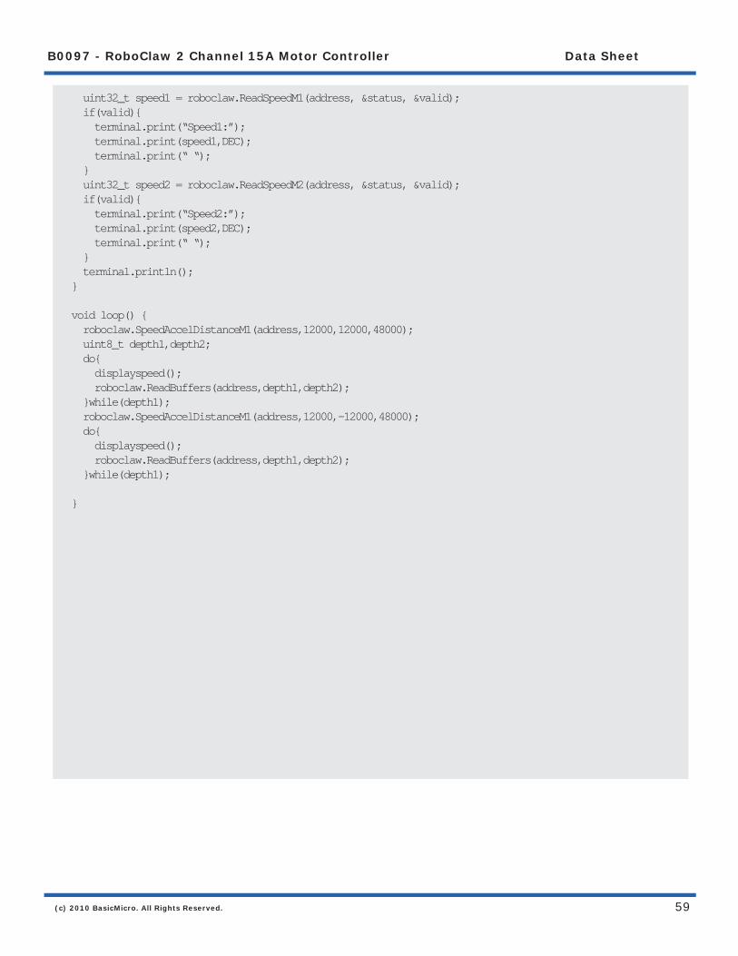
Speed Controlled by Quadrature Encoders - Arduino ExampleThe following example was written using an BasicATOM Pro. RoboClaw was connected as shown in both packet serial wiring and quadrature encoder wiring diagrams.
The example will command a 4wheel robot to move forward, backward, right turn and left turn slowly. You can change the speed by adjusting the value of Speed and Speed2 variables.
//Basic Micro Robo Claw Packet Serial Mode.//Switch settings: SW3=ON, SW4=ON, SW5=ON
#include “BMSerial.h”#include “RoboClaw.h”
#defi ne address 0x80
#defi ne Kp 0x00010000#defi ne Ki 0x00008000#defi ne Kd 0x00004000#defi ne qpps 44000
BMSerial terminal(0,1);RoboClaw roboclaw(5,6);
void setup() { terminal.begin(38400); roboclaw.begin(38400); roboclaw.SetM1Constants(address,Kd,Kp,Ki,qpps); roboclaw.SetM2Constants(address,Kd,Kp,Ki,qpps); }
void displayspeed(void){ uint8_t status; bool valid; uint32_t enc1= roboclaw.ReadEncM1(address, &status, &valid); if(valid){ terminal.print(“Encoder1:”); terminal.print(enc1,DEC); terminal.print(“ “); terminal.print(status,HEX); terminal.print(“ “); } uint32_t enc2 = roboclaw.ReadEncM2(address, &status, &valid); if(valid){ terminal.print(“Encoder2:”); terminal.print(enc2,DEC); terminal.print(“ “); terminal.print(status,HEX); terminal.print(“ “); }
(c) 2010 BasicMicro. All Rights Reserved.
B0097 - RoboClaw 2 Channel 15A Motor Controller Data Sheet
59
uint32_t speed1 = roboclaw.ReadSpeedM1(address, &status, &valid); if(valid){ terminal.print(“Speed1:”); terminal.print(speed1,DEC); terminal.print(“ “); } uint32_t speed2 = roboclaw.ReadSpeedM2(address, &status, &valid); if(valid){ terminal.print(“Speed2:”); terminal.print(speed2,DEC); terminal.print(“ “); } terminal.println();}
void loop() { roboclaw.SpeedAccelDistanceM1(address,12000,12000,48000); uint8_t depth1,depth2; do{ displayspeed(); roboclaw.ReadBuffers(address,depth1,depth2); }while(depth1); roboclaw.SpeedAccelDistanceM1(address,12000,-12000,48000); do{ displayspeed(); roboclaw.ReadBuffers(address,depth1,depth2); }while(depth1); }

(c) 2010 BasicMicro. All Rights Reserved.
B0097 - RoboClaw 2 Channel 15A Motor Controller Data Sheet
60
Reading Quadrature Encoder - BasicATOM Pro ExampleThe example was tested with a BasicATOM Pro. RoboClaw was connected as shown in both packet serial wiring and quadrature encoder wiring diagrams.
The example will read the speed, total ticks and direction of each encoder. Connect to the program using the Basic Micro Studio terminal window set to 38400 baud. The program will display the values of each encoders current count along with each encoder status bit in binary and the direction bit. As the encoder is turned it will update the screen.
Encoder1 Var LongEncoder2 Var LongStatus Var ByteCRC Var Byte
ENABLEHSERIAL ;used on AtomPro24 and AtomPro28. AtomPro40 and ARC-32 use EnableHSerial2
SetHSerial H38400,H8DATABITS,HNOPARITY,H1STOPBITS
Pause 250
Hserout [128, 20, (148 & 0x7F)]; Resets encoder registers
Main Pause 100
ReadEncoderM1 Hserout [128, 16] Hserin [Encoder1.byte3, Encoder1.Byte2, Encoder1.Byte1, Encoder1.Byte0, Status, crc] Serout s_out, i38400, [0,”Encoder1: “, SDEC Encoder1, 13, “Status Byte: “, BIN Status]
ReadSpeedM1 Hserout [128, 18] Hserin [Encoder1.byte3, Encoder1.Byte2, Encoder1.Byte1, Encoder1.Byte0, Status, crc] Serout s_out, i38400, [13, 13, “Speed: “, DEC Encoder1, 13, “Direction: “, DEC Status]
ReadEncoderM2 Hserout [128, 17] Hserin [Encoder2.byte3, Encoder2.Byte2, Encoder2.Byte1, Encoder2.Byte0, Status, crc] Serout s_out, i38400, [13, 13, “Encoder2: “, SDEC Encoder2, 13, “Status Byte: “, BIN Status]
ReadSpeedM2 Hserout [128, 19] Hserin [Encoder2.byte3, Encoder2.Byte2, Encoder2.Byte1, Encoder2.Byte0, Status, crc] Serout s_out, i38400, [13, 13, “Speed: “, DEC Encoder2, 13, “Direction: “, DEC Status]
Goto Main

(c) 2010 BasicMicro. All Rights Reserved.
B0097 - RoboClaw 2 Channel 15A Motor Controller Data Sheet
61
Speed Controlled by Quadrature Encoders - BasicATOM Pro ExampleThe following example was written using an BasicATOM Pro. RoboClaw was connected as shown in both packet serial wiring and quadrature encoder wiring diagrams.
The example will command a 4wheel robot to move forward, backward, right turn and left turn slowly. You can change the speed by adjusting the value of Speed and Speed2 variables.
CMD var byteSpeed var longSpeed2 var longCRC var byteAddress con 128
ENABLEHSERIAL ;used on AtomPro24 and AtomPro28. AtomPro40 and ARC-32 use EnableHSerial2SetHSerial H38400,H8DATABITS,HNOPARITY,H1STOPBITS
Mixed_Forward CMD=37 Speed=12000 Speed2=12000 CRC = (address + cmd + speed.byte3 + speed.byte2 + speed.byte1 + speed.byte0 + | speed2.byte3 + speed2.byte2 + speed2.byte1 + speed2.byte0)&0x7F hserout [address,cmd,speed.byte3,speed.byte2,speed.byte1,speed.byte0, | speed2.byte3,speed2.byte2,speed2.byte1,speed2.byte0,crc] pause 4000
Mixed_Backward CMD=37 Speed=-12000 Speed2=-12000 CRC = (address + cmd + speed.byte3 + speed.byte2 + speed.byte1 + speed.byte0 + | speed2.byte3 + speed2.byte2 + speed2.byte1 + speed2.byte0)&0x7F hserout [address,cmd,speed.byte3,speed.byte2,speed.byte1,speed.byte0, | speed2.byte3,speed2.byte2,speed2.byte1,speed2.byte0,crc] pause 4000
Mixed_Left CMD=37 Speed=-12000 Speed2=12000 CRC = (address + cmd + speed.byte3 + speed.byte2 + speed.byte1 + speed.byte0 + | speed2.byte3 + speed2.byte2 + speed2.byte1 + speed2.byte0)&0x7F hserout [address,cmd,speed.byte3,speed.byte2,speed.byte1,speed.byte0, | speed2.byte3,speed2.byte2,speed2.byte1,speed2.byte0,crc] pause 4000
Mixed_Right CMD=37 Speed=12000 Speed2=-12000 CRC = (address + cmd + speed.byte3 + speed.byte2 + speed.byte1 + speed.byte0 + | speed2.byte3 + speed2.byte2 + speed2.byte1 + speed2.byte0)&0x7F hserout [address,cmd,speed.byte3,speed.byte2,speed.byte1,speed.byte0, | speed2.byte3,speed2.byte2,speed2.byte1,speed2.byte0,crc] pause 4000
Mixed_Stop CMD=37 Speed=0 Speed2=0 CRC = (address + cmd + speed.byte3 + speed.byte2 + speed.byte1 + speed.byte0 + | speed2.byte3 + speed2.byte2 + speed2.byte1 + speed2.byte0)&0x7F hserout [address,cmd,speed.byte3,speed.byte2,speed.byte1,speed.byte0, | speed2.byte3,speed2.byte2,speed2.byte1,speed2.byte0,crc]
stop

(c) 2010 BasicMicro. All Rights Reserved.
B0097 - RoboClaw 2 Channel 15A Motor Controller Data Sheet
62
Electrical Characteristics
Characteristic Rating Min Typ MaxPulse Per Second PPS 0 8,000,000Main Battery (B+ / B-) VDC 6 24 30Logic Battery (LB+ / LB-) VDC 6 12 30External Current Draw (BEC) A 3ALogic Circuit mA 90Motor Current Per Channel A 15 30I/O Voltages VDC 0 5I/O Logic TTL 5Tempature Range C -40 +125

(c) 2010 BasicMicro. All Rights Reserved.
B0097 - RoboClaw 2 Channel 15A Motor Controller Data Sheet
63
WarrantyBasic Micro warranties its products against defects in material and workmanship for a period of 90 days. If a defect is discovered, Basic Micro will, at our discretion, repair, replace, or refund the purchase price of the product in question. Contact us at [email protected]. No returns will be accepted without the proper authorization.
Copyrights and TrademarksCopyright© 2010 by Basic Micro, Inc. All rights reserved. PICmicro® is a trademark of Microchip Technology, Inc. The Basic Atom and Basic Micro are registered trademarks of Basic Micro Inc. Other trademarks mentioned are registered trademarks of their respective holders.
DisclaimerBasic Micro cannot be held responsible for any incidental, or consequential damages resulting from use of products manufactured or sold by Basic Micro or its distributors. No products from Basic Micro should be used in any medical devices and/or medical situations. No product should be used in a life support situation.
Contacts Email: [email protected] Tech support: [email protected] Web: http://www.basicmicro.com
Discussion ListA web based discussion board is maintained at http://www.basicmicro.com.
Technical SupportTechnical support is made available by sending an email to [email protected]. All email will be answered within 48 hours. All general syntax and programming questions, unless deemed to be a software issue, will be referred to the on-line discussion forums.