automated plastic extruder doser manual
TRANSCRIPT

Automated Plastic Extruder Doser Manual
ENGR 480: Manufacturing
Fall 2015
Produced by Team Loewen:
Nathan Loewen
Zachary Arnott Rodrigo Alvares
Kendrick Rady
2
Table of Contents
Table of Figures ................................................................................................................. 3
Introduction ........................................................................................................................ 4
Loading Machine ................................................................................................................ 5
Starting Machine ................................................................................................................ 5
Clearing Machine ............................................................................................................... 6
Description of Operation .................................................................................................... 7
Station 1 – The Dispensing Station .................................................................................. 7
Station 2 – The Weigh Station ......................................................................................... 8
Station 3 – The Mixing Station ......................................................................................... 10
Maintenance ...................................................................................................................... 11
Stepper Motor Configuration .............................................................................................. 11
Wiring Diagram .................................................................................................................. 12
Future Improvements ......................................................................................................... 13
Performance Data .............................................................................................................. 13
State Diagram .................................................................................................................... 14
PLC Ladder Logic .............................................................................................................. 15

3
Table of Figures
Figure 1. Complete Assembly ............................................................................................... 4
Figure 2. The Button Layout ................................................................................................. 5
Figure 3. The Dispensing Station ......................................................................................... 6
Figure 4. Turntable ............................................................................................................... 7
Figure 5. Dispensing Station Layout ..................................................................................... 8
Figure 6. The Weigh Station ................................................................................................. 9
Figure 7. The Weigh Station Layout ..................................................................................... 9
Figure 8. The Mixing Station ................................................................................................. 10
Figure 9. The Mixer .............................................................................................................. 11
Figure 10. Wiring Diagram .................................................................................................... 12
Figure 11. Load Error Data ................................................................................................... 13
Figure 12. State Diagram ...................................................................................................... 14
Figure 13. PLC Ladder Logic ................................................................................................ 15
4
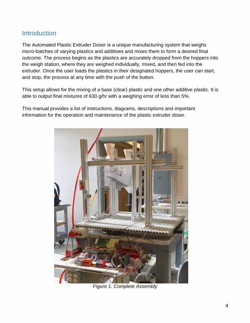
Introduction
The Automated Plastic Extruder Doser is a unique manufacturing system that weighs
micro-batches of varying plastics and additives and mixes them to form a desired final
outcome. The process begins as the plastics are accurately dropped from the hoppers into
the weigh station, where they are weighed individually, mixed, and then fed into the
extruder. Once the user loads the plastics in their designated hoppers, the user can start,
and stop, the process at any time with the push of the button.
This setup allows for the mixing of a base (clear) plastic and one other additive plastic. It is
able to output final mixtures of 630 g/hr with a weighing error of less than 5%.
This manual provides a list of instructions, diagrams, descriptions and important
information for the operation and maintenance of the plastic extruder doser.
Figure 1. Complete Assembly
5
Loading Machine
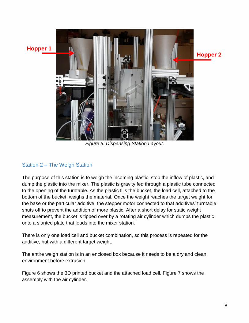
The loading of the machine consists of filling the hoppers with the different types of plastics.
This should be done when any given hopper is empty.
The locations of the designated hoppers are shown in figure 5.
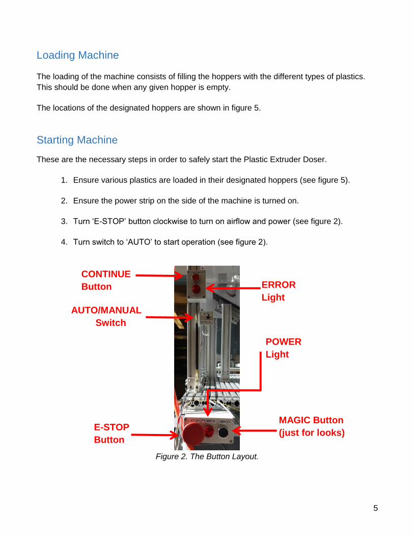
Starting Machine
These are the necessary steps in order to safely start the Plastic Extruder Doser.
1. Ensure various plastics are loaded in their designated hoppers (see figure 5).
2. Ensure the power strip on the side of the machine is turned on.
3. Turn ‘E-STOP’ button clockwise to turn on airflow and power (see figure 2).
4. Turn switch to ‘AUTO’ to start operation (see figure 2).
Figure 2. The Button Layout.
CONTINUE
Button
AUTO/MANUAL
Switch
ERROR
Light
POWER
Light
MAGIC Button
(just for looks)
E-STOP
Button
6
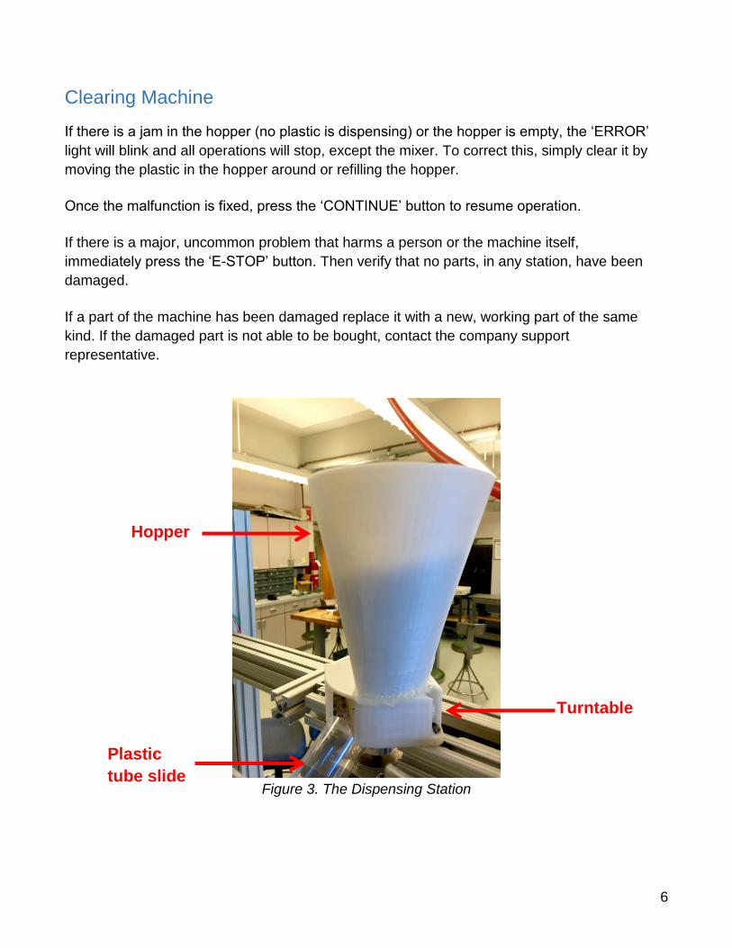
Clearing Machine
If there is a jam in the hopper (no plastic is dispensing) or the hopper is empty, the ‘ERROR’
light will blink and all operations will stop, except the mixer. To correct this, simply clear it by
moving the plastic in the hopper around or refilling the hopper.
Once the malfunction is fixed, press the ‘CONTINUE’ button to resume operation.
If there is a major, uncommon problem that harms a person or the machine itself,
immediately press the ‘E-STOP’ button. Then verify that no parts, in any station, have been
damaged.
If a part of the machine has been damaged replace it with a new, working part of the same
kind. If the damaged part is not able to be bought, contact the company support
representative.
Figure 3. The Dispensing Station
Hopper
Turntable
Plastic
tube slide
7
Description of Operation
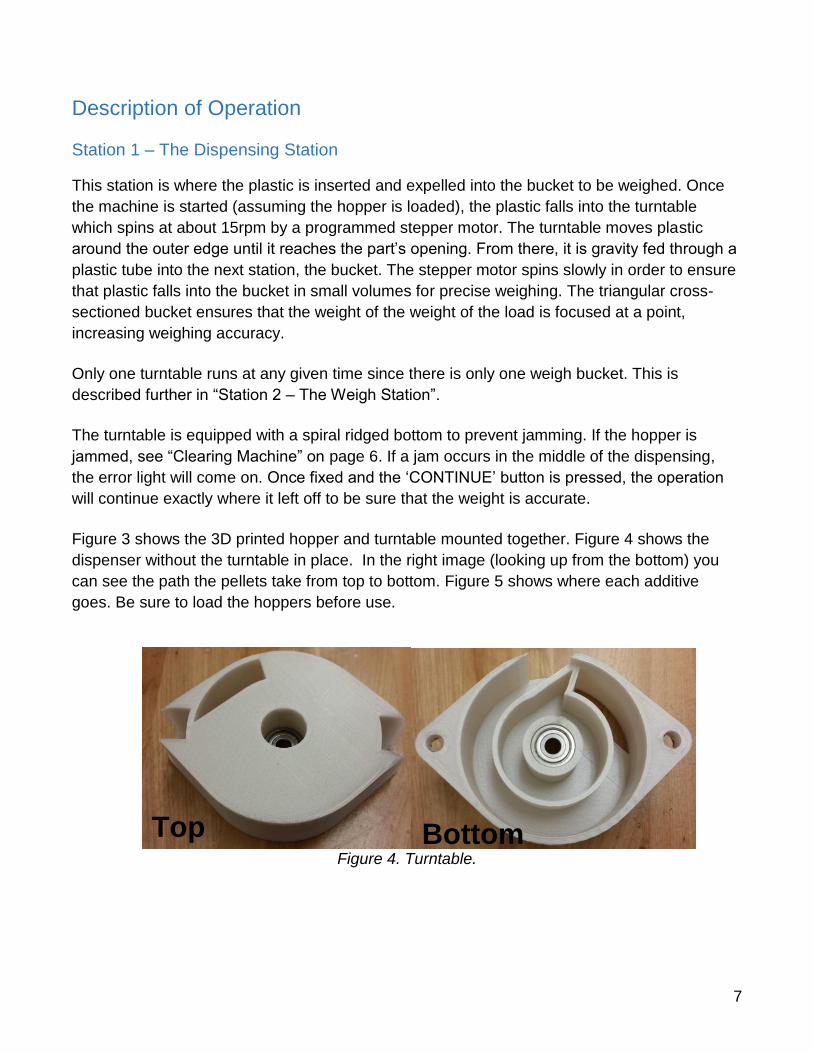
Station 1 – The Dispensing Station
This station is where the plastic is inserted and expelled into the bucket to be weighed. Once
the machine is started (assuming the hopper is loaded), the plastic falls into the turntable
which spins at about 15rpm by a programmed stepper motor. The turntable moves plastic
around the outer edge until it reaches the part’s opening. From there, it is gravity fed through a
plastic tube into the next station, the bucket. The stepper motor spins slowly in order to ensure
that plastic falls into the bucket in small volumes for precise weighing. The triangular cross-
sectioned bucket ensures that the weight of the weight of the load is focused at a point,
increasing weighing accuracy.
Only one turntable runs at any given time since there is only one weigh bucket. This is
described further in “Station 2 – The Weigh Station”.
The turntable is equipped with a spiral ridged bottom to prevent jamming. If the hopper is
jammed, see “Clearing Machine” on page 6. If a jam occurs in the middle of the dispensing,
the error light will come on. Once fixed and the ‘CONTINUE’ button is pressed, the operation
will continue exactly where it left off to be sure that the weight is accurate.
Figure 3 shows the 3D printed hopper and turntable mounted together. Figure 4 shows the
dispenser without the turntable in place. In the right image (looking up from the bottom) you
can see the path the pellets take from top to bottom. Figure 5 shows where each additive
goes. Be sure to load the hoppers before use.
Figure 4. Turntable.
Top Bottom
8
Figure 5. Dispensing Station Layout.
Station 2 – The Weigh Station
The purpose of this station is to weigh the incoming plastic, stop the inflow of plastic, and
dump the plastic into the mixer. The plastic is gravity fed through a plastic tube connected
to the opening of the turntable. As the plastic fills the bucket, the load cell, attached to the
bottom of the bucket, weighs the material. Once the weight reaches the target weight for
the base or the particular additive, the stepper motor connected to that additives’ turntable
shuts off to prevent the addition of more plastic. After a short delay for static weight
measurement, the bucket is tipped over by a rotating air cylinder which dumps the plastic
onto a slanted plate that leads into the mixer station.
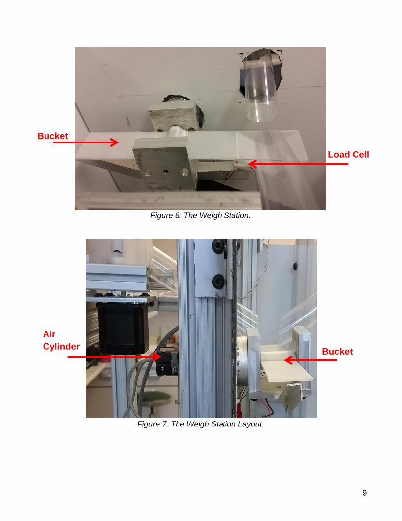
There is only one load cell and bucket combination, so this process is repeated for the
additive, but with a different target weight.
The entire weigh station is in an enclosed box because it needs to be a dry and clean
environment before extrusion.
Figure 6 shows the 3D printed bucket and the attached load cell. Figure 7 shows the
assembly with the air cylinder.
Hopper 1 Hopper 2
9
Figure 6. The Weigh Station.
Figure 7. The Weigh Station Layout.
Load Cell
Bucket
Air
Cylinder Bucket
10
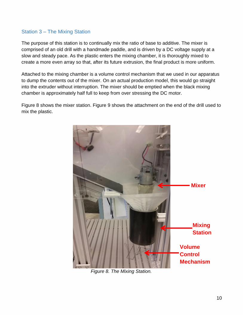
Station 3 – The Mixing Station
The purpose of this station is to continually mix the ratio of base to additive. The mixer is
comprised of an old drill with a handmade paddle, and is driven by a DC voltage supply at a
slow and steady pace. As the plastic enters the mixing chamber, it is thoroughly mixed to
create a more even array so that, after its future extrusion, the final product is more uniform.
Attached to the mixing chamber is a volume control mechanism that we used in our apparatus
to dump the contents out of the mixer. On an actual production model, this would go straight
into the extruder without interruption. The mixer should be emptied when the black mixing
chamber is approximately half full to keep from over stressing the DC motor.
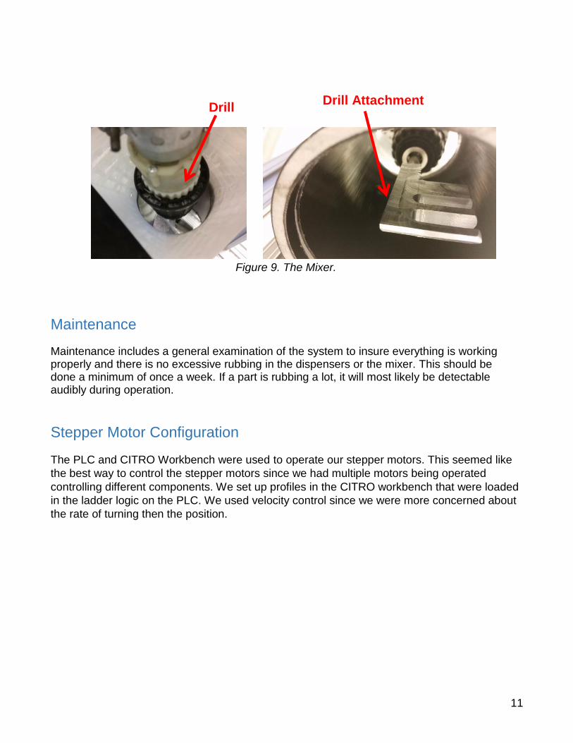
Figure 8 shows the mixer station. Figure 9 shows the attachment on the end of the drill used to
mix the plastic.
Figure 8. The Mixing Station.
Mixer
Mixing
Station
Volume
Control
Mechanism
11
Figure 9. The Mixer.
Maintenance
Maintenance includes a general examination of the system to insure everything is working properly and there is no excessive rubbing in the dispensers or the mixer. This should be done a minimum of once a week. If a part is rubbing a lot, it will most likely be detectable audibly during operation.
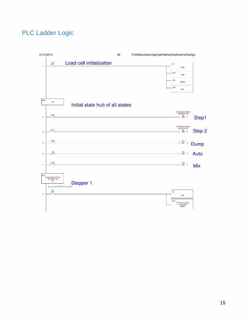
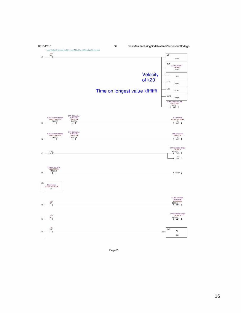
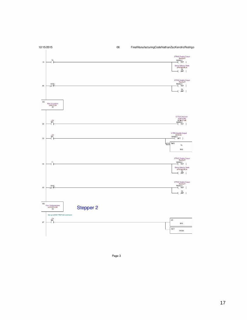
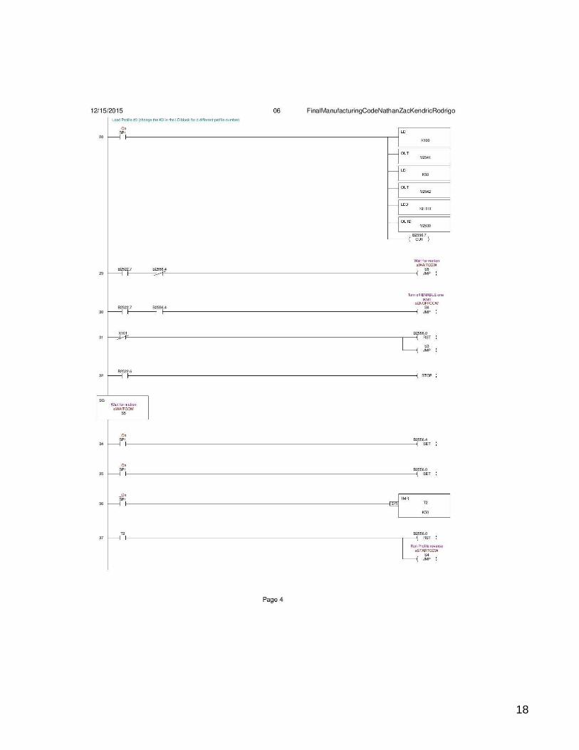
Stepper Motor Configuration
The PLC and CITRO Workbench were used to operate our stepper motors. This seemed like
the best way to control the stepper motors since we had multiple motors being operated
controlling different components. We set up profiles in the CITRO workbench that were loaded
in the ladder logic on the PLC. We used velocity control since we were more concerned about
the rate of turning then the position.
Drill Attachment Drill
12
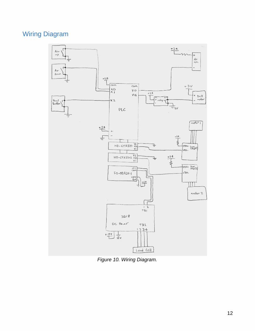
Wiring Diagram
Figure 10. Wiring Diagram.
13
Future Improvements
In the future, it would be beneficial to add more additives to allow multiple additives to be
dispensed simultaneously. Our setup has the ability to add one material to the base resin.
Ideally, it would be nice to have at least three total additives. We believe that the best way of
doing this would be to add a hopper/turntable for each desired additive and one bucket per two
desired additives while making sure they all dump into the mixer (i.e. setting up the turntables
and buckets in a circular pattern around the mixer).
Furthermore, if the machine was purposed for plastic production on a slightly larger scale, it
would be necessary only increase the size of the load cell and bucket since the hopper and
turntable can provide adequate high-volume flow in the current setup. For much higher output,
larger parts, multiple dumping mechanisms, and higher speed motors would be necessary.
To eliminate static electricity in the plastic, it would be best if all of the parts of the assembly
were made of metal instead of the 3D plastic parts that we used.
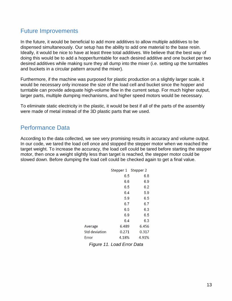
Performance Data
According to the data collected, we see very promising results in accuracy and volume output. In our code, we tared the load cell once and stopped the stepper motor when we reached the target weight. To increase the accuracy, the load cell could be tared before starting the stepper motor, then once a weight slightly less than target is reached, the stepper motor could be slowed down. Before dumping the load cell could be checked again to get a final value.
Figure 11. Load Error Data
14
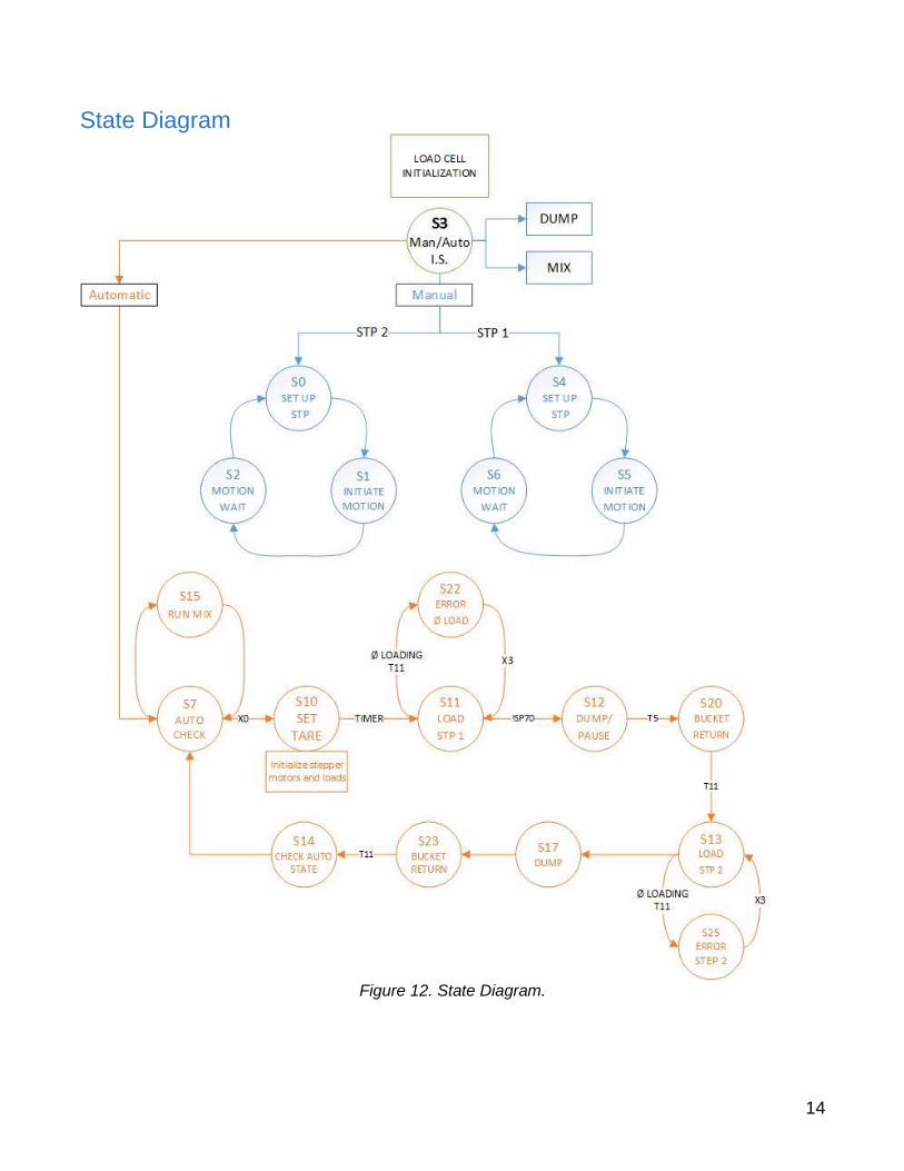
State Diagram
Figure 12. State Diagram.
15
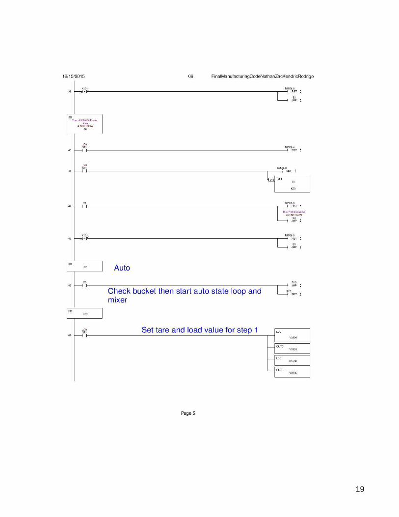
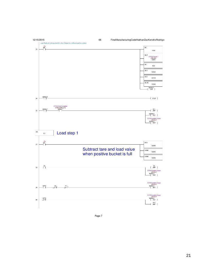
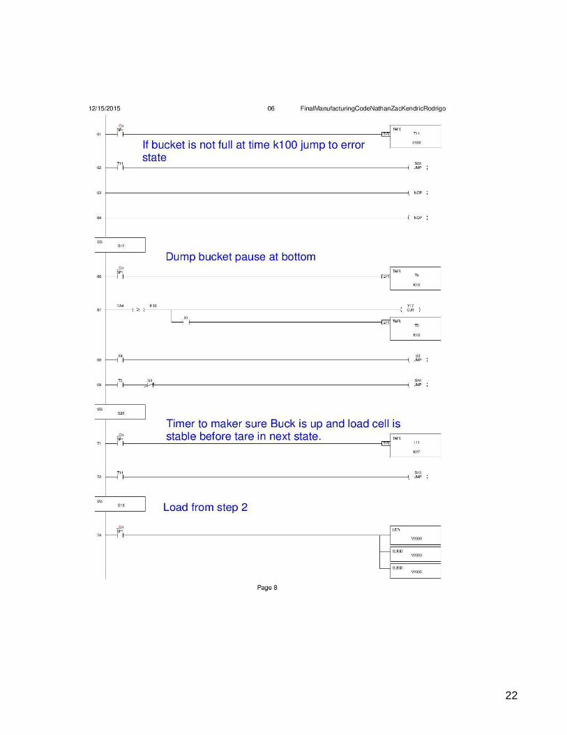
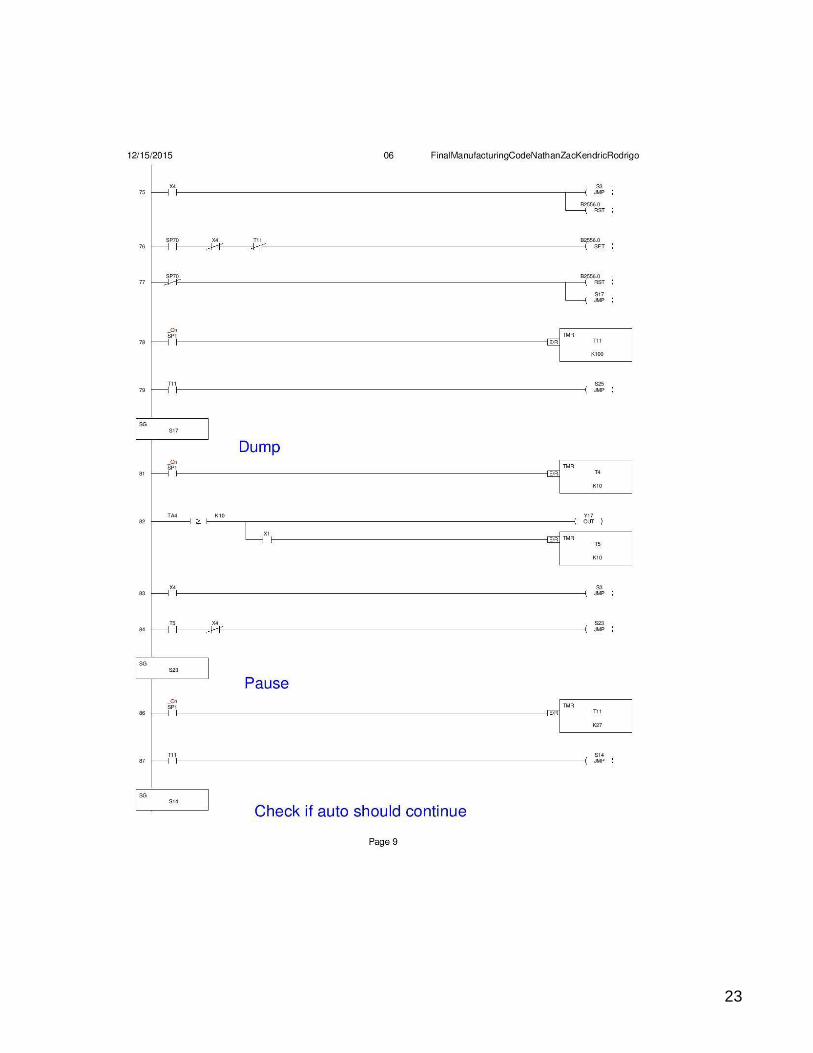
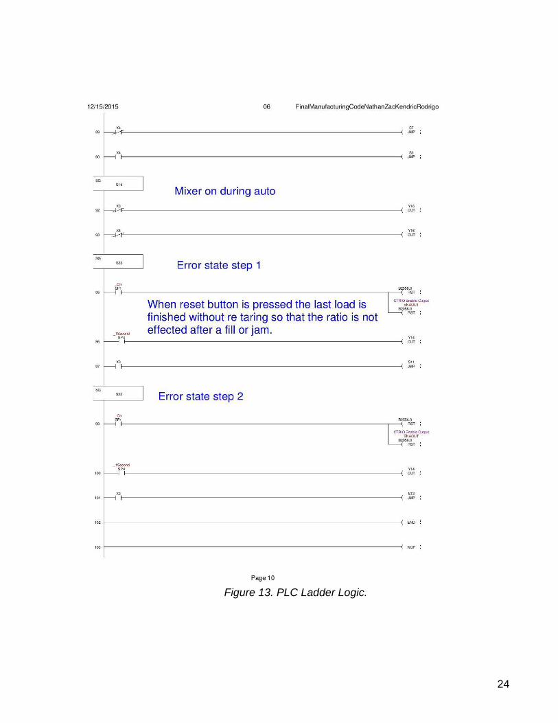
PLC Ladder Logic
16
17
18
19

20
21
22
23
24
Figure 13. PLC Ladder Logic.