auto class notes
TRANSCRIPT

Automobile Engineering- Introduction and Engine
Components
ByDr.S.John Alexis

Automobile EngineeringAn automobile is a self propelled vehicle used for the transportation of goods and passengers.A self propelled vehicle is that in which power required for the propulsion is produced within.
Types of Automobiles1. Purpose:
a. Passenger vehicles – Car, Bus, Jeepb. Goods vehicles – Truckc. Special purpose vehicles – Dumper,BullDozer,Mobile
crane,Forklift,Loader2. Capacity:
a. Light Motor Vehicle – Car ,Jeepb. Heavy Motor Vehicle – Bus, Truck
3. Fuel used:a. Petrol vehicles – Scooter, Motor cycle, car, Jeepb. Diesel vehicles _ Car, Bus, Truck, Tractorc. Electric cab vehicles _ Battery bike, battery Truck, Fork liftd. Steam type vehicles _ Steam road rollere. Solar type vehicles _ Solar car

4. Wheels:a. Two wheelers _ Scooter, Motor cycle, Moped
b. Three wheelers _ Autorickshaw, Tempoc. Four Wheelers _ Car, Jeepd. Six Wheelers _ Truck, Bus
5. Drive of the Vehicles:a. Left hand Drive b. Right hand Drivec. Front wheel drive d. Real wheel drive
All wheel drive

Engine Locations
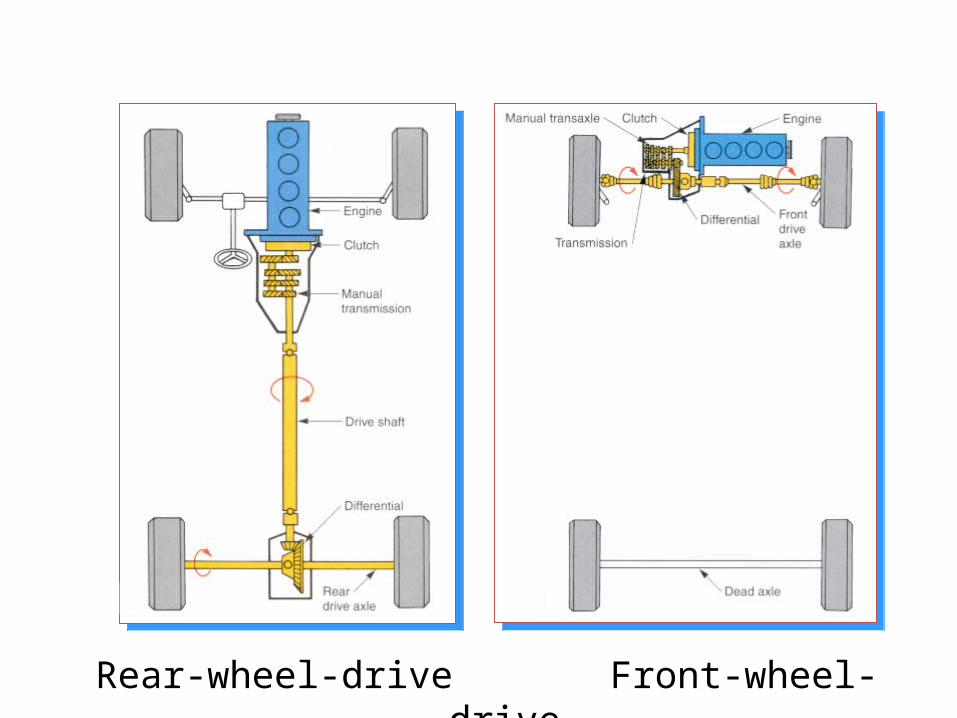
Rear-wheel-drive Front-wheel-drive

Four Wheel Drive 4X4

Drive Shaft

CHASSIS FRAME AND BODYIntroduction of Chassis Frame:
Chassis is a French term and was initially used to denote the frame parts or Basic Structure of the vehicle. It is the back bone of the vehicle. A vehicle with out body is called Chassis.
The components of the vehicle like Power plant, Transmission System, Axles, Wheels and Tyres, Suspension, Controlling Systems like Braking, Steering etc., and also electrical system parts are mounted on the Chassis frame. It is the main mounting for all the components including the body.
So it is also called as Carrying Unit.

The following main components of the Chassis are
1. Frame: it is made up of long two members called side members riveted together with the help of number of cross members.
2. Engine or Power plant: It provides the source of power
3. Clutch: It connects and disconnects the power from the engine fly wheel to the transmission system.
4. Gear Box
5. U Joint
6. Propeller Shaft
7. Differential

FUNCTIONS OF THE CHASSIS FRAME:1. To carry load of the passengers or goods carried in the body.2. To support the load of the body, engine, gear box etc.,3. To withstand the forces caused due to the sudden braking or acceleration4. To withstand the stresses caused due to the bad road condition.5. To withstand centrifugal force while cornering
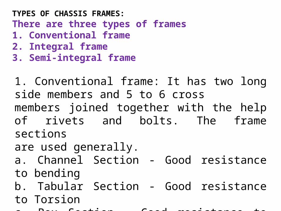
TYPES OF CHASSIS FRAMES:There are three types of frames1. Conventional frame2. Integral frame3. Semi-integral frame
1. Conventional frame: It has two long side members and 5 to 6 crossmembers joined together with the help of rivets and bolts. The frame sectionsare used generally.a. Channel Section - Good resistance to bendingb. Tabular Section - Good resistance to Torsionc. Box Section - Good resistance to both bending andTorsion

2. Integral Frame: This frame is used now a days in most of the cars. There is no frame and all the assembly units are attached to the body. All the functions of the frame carried out by the body itself. Due to elimination of long frame it is cheaper and due to less weight most economical also. Only disadvantage is repairing is difficult.
3. Semi - Integral Frame: In some vehicles half frame is fixed in the front end on which engine gear box and front suspension is mounted. It has the advantage when the vehicle is met with accident the front frame can be taken easily to replace the damaged chassis frame. This type of frame is used in FIAT cars and some of the European and American cars.

VARIOUS LOADS ACTING ON THE FRAME:
Various loads acting on the frame are1. Short duration Load - While crossing a
broken patch.2. Momentary duration Load - While taking a
curve.3. Impact Loads - Due to the collision of the vehicle.4. Inertia Load - While applying brakes.5. Static Loads - Loads due to chassis parts.6. Over Loads - Beyond Design capacity.

The Automobile bodies are divided in three groups
According to Chassis design the body can divided into1. Conventional Type2. Integral Type3. Semi- Integral Type
According to other usage:1. Light vehicle Bodies - cars, jeeps2. Heavy vehicle Bodies – Busses, Lorries3. Medium vehicle Bodies - Vans, Metadoors

REQUIREMENTS OF BODIES FOR VARIOUS TYPES OF VECHILE:The body of the most vehicle should fulfill the following requirements:
1. The body should be light.2. It should have minimum number of components.3. It should provide sufficient space for passengers and luggage.4. It should withstand vibrations while in motion.5. It should offer minimum resistance to air.6. It should be cheap and easy in manufacturing.7. It should be attractive in shape and colour.8. It should have uniformly distributed load.9. It should have long fatigue life10.It should provide good vision and ventilation.


18
Automobile Bodies
• Most made of stamped steel parts
• A few cars made of aluminum (NSX Cadillac Allenta)
• Some use composite materials (Saturn or GM Minivan)

19
Chassis or Frame
• Under lying structure of all vehicles
• Three types of frame:• 1 – Full frame• 2 – Unitized frame
called unibody• 3 – Space frame

20
Full Frame Chassis
• Uses welded steel alloy metal
• C-channel or box frame construction
• Note engine cradle in front and rear axle hump in rear
• Used on large cars and most all trucks
• Body made in separate unit and bolted to chassis

21
Unitized Body Construction
• Called Unibody• All body and frame
parts welded together• Light weight but
strong structurally• Most cars use this
construction

22
Space Frame Construction
• Newest type of construction
• Hybrid unibody• Used on race cars first
but now used in passenger cars
• Many use plastic fenders and body panels

23
Chassis Related Systems
• Braking system
• Suspension system
• Steering system

Automobile Body Parts


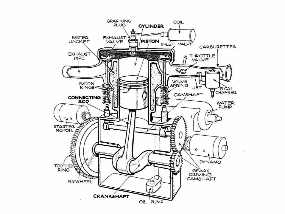
Basic Engine Parts
The core of the engine is the cylinder, with the piston moving up and down inside the cylinder. Most cars have more than one cylinder (four, six and eight
cylinders are common).
In a multi-cylinder engine, the cylinders usually are arranged in one of three ways:
inline, V or flat (also known as horizontally opposed or boxer), as shown in the following figures.
1) Inline - The cylinders are arranged in a line in a single bank.

V - The cylinders are arranged in two banks set at an angle to one another.
Flat - The cylinders are arranged in two banks on opposite sides of the engine


Basically the cylinder liner is a cylindrical shell which acts as the enclosure in which the combustion takes place.
The cylinder liner forms the cylindrical space in which the piston reciprocates.It is under the fluid pressure due to combustion and hence must withstand the high level of hoop stress induced in it.
Cylinder liner

A cylinder liner is a removable component, cylindrical in shape, inserted into the engine block. It provides the surface for the piston to slide and carry out its compression task. It can be replaced when worn out. Cylinder liners are made from close grained cast iron. In four stroke cycle engines they are simple cylindrical shapes flanged at the top end to provide location and secure them in the cylinder blocks or to the water jacket.


Cylinder block is made from grey cast iron, the cylinder liner is manufactured from cast iron alloyed with chromium, vanadium and molybdenum. Cast iron contains graphite, which assists lubrication, whereas the alloying elements help resists corrosion as well as improve wear resistance at higher temperature.In wet liners the water is in direct contact with outer surface of the liner whereas in dry liners the water is in indirect contact with outer surface of the liner, i.e. cylinder casting contains wet jackets.


Cylinder Block

A cylinder block is a unit comprising several cylinders (including their cylinder walls, coolant passages, cylinder sleeves if any, and so forth).The metal casting in which the cylinders of an internal-combustion engine are bored.
The metal casting containing the cylinders and cooling channels or fins of a reciprocating internal-combustion engine.
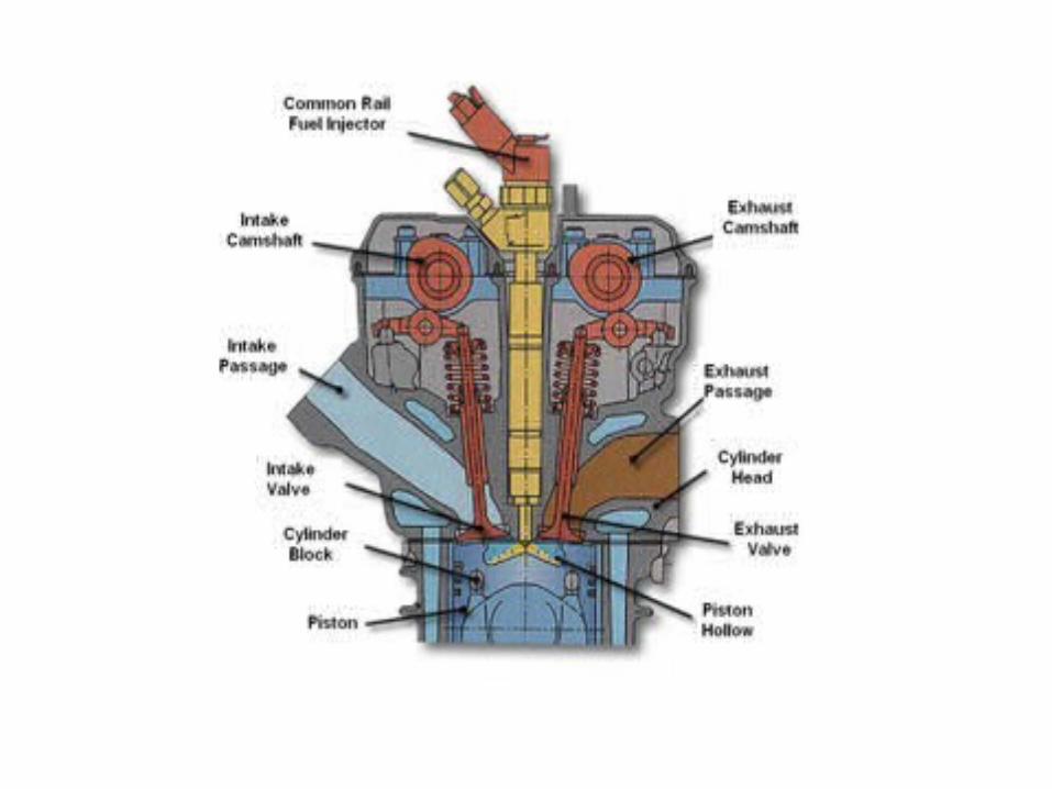
What Is the Function of Cylinder Head?
The function of a cylinder head is to coordinate airflow in and out of the engine. The cylinder head also acts as a housing for the valve-train and focuses the combustion pressure on the piston head.


PistonA piston is a cylindrical piece of metal in the form of a inverted bucket that moves up and down inside the cylinder. Pistons are constructed of aluminium alloy. Parts include top, ring grooves, ring lands, skirt and piston pin boss. Cooling fins on the bottom help the oil carry heat away from the piston top.


A piston of an Internal combustion engine serves the following functions:1. The piston receives the thrust produced by combustion
and transmits the power to the connecting rod.2. It reciprocated to cause different strokes3. It acts as a bearing to the small end of connecting rod 4. It forms a movable wall of the combustion chamber5. It transmits turning force to the crankshaft via the
connecting rod6. It functions like a crosshead and transmits side
thrust ,which is due to the angularity of the connecting rods, to the cylinder walls

4. The piston operation must not be noisy
5. The piston must have less coefficient of expansion
3. The piston must be a good conductor of heat so that detonation is suppressed and higher compression ratio is possible to get fuel economy.
The piston must possess the following qualities:1. It must be strong enough to withstand high pressure
caused due to combustion of fuel
2. It must be light in weight to have minimum primary and secondary forces, which are caused due to the inertia forces of the reciprocating masses.


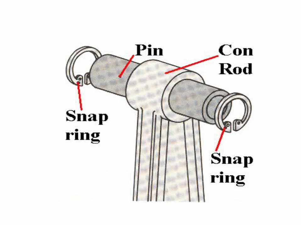
A piston pin, also known as a wrist pin, is a hardened steel pin which connects an engine's piston to a connecting rod. The piston pin is hollow to reduce weight and is held in place with a number of different methods.
Piston pins are made of hardened steel, many high-performance applications utilize tool steel pins. These tool steel pins are the strongest and most durable, can withstand ultra high horsepower.
Piston: aluminum alloy; cast or forged Connecting rod: low carbon, high strength steel; forged, powder metallurgy Piston pin: low carbon, high strength steel;


A connecting rod is an engine component that transfers motion from the piston to the crankshaft and functions as a lever arm.
Connecting rods are commonly made from cast aluminum alloy and are designed to withstand dynamic stresses from combustion and piston movement.
The small end of the connecting rod connects to the piston with a piston pin.
The piston pin, or wrist pin, provides a pivot point between the piston and connecting rod.
Spring clips, or piston pin locks, are used to hold the piston pin in place.

The big end of the connecting rod connects to the crankpin journal to provide a pivot point on the crankshaft. Connecting rods are produces as one piece or two-piece components. A rod cap is the removable section of a two-piece connecting rod that provides a bearing surface for the crankpin journal. The rod cap is attached to the connecting rod with two cap screws for installation and removal from the crankshaft.
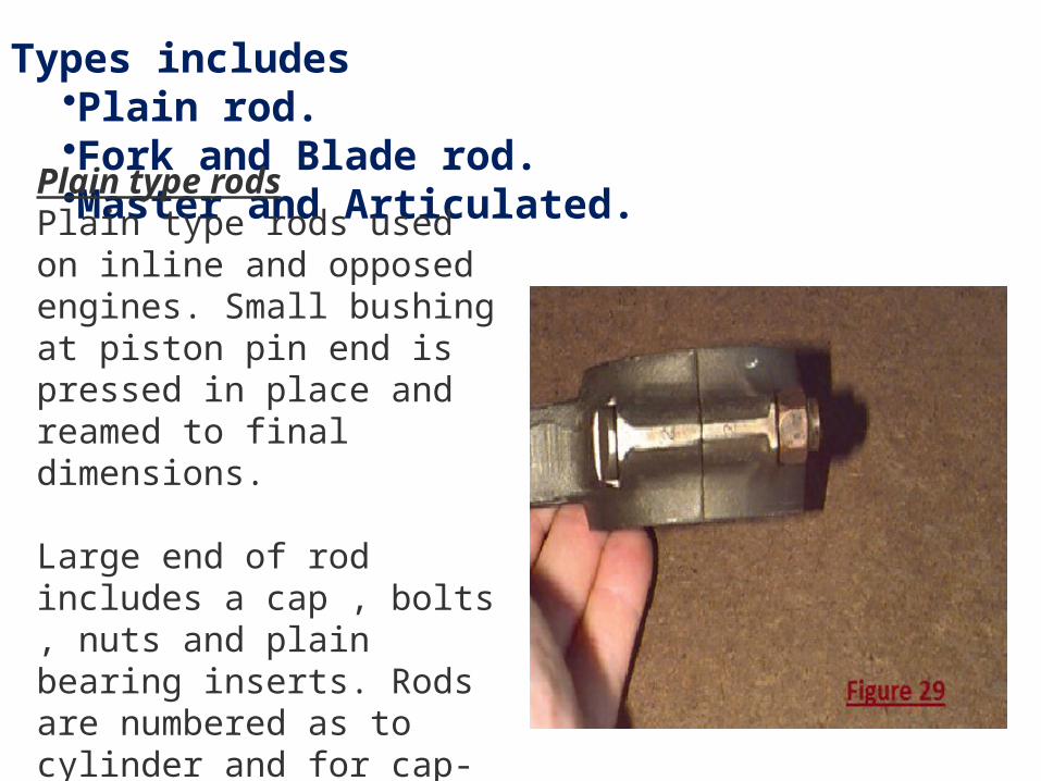
Types includes •Plain rod.•Fork and Blade rod.•Master and Articulated.
Plain type rodsPlain type rods used on inline and opposed engines. Small bushing at piston pin end is pressed in place and reamed to final dimensions. Large end of rod includes a cap , bolts , nuts and plain bearing inserts. Rods are numbered as to cylinder and for cap-to-rod alignment.

Fork and blade connecting rod.Fork and blade connecting rods are used on "V" type engines. One rod inside another allows cylinders to be aligned and to share a common location on the crankshaft.

Master and Articulating rod.Master and Articulating rods are used on radial engines Uses "Knuckle pins" to retain articulated rods to master.

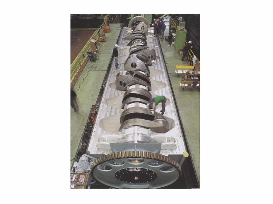
The crankshaft, sometimes abbreviated as crank, is the part of an engine that translates reciprocating linear piston motion into rotation.
To convert the reciprocating motion into rotation, the crankshaft has "crank throws" or "crankpins", additional bearing surfaces whose axis is offset from that of the crank, to which the "big ends" of the connecting rods from each cylinder attach.
It is typically connected to a flywheel to reduce the pulsation characteristic of the four-stroke cycle, and sometimes a torsional or vibrational damper at the opposite end, to reduce the torsional vibrations often caused along the length of the crankshaft by the cylinders farthest from the output end acting on the torsional elasticity of the metal.


Crankshaft Materials
• Cast iron• Cast steel• Forged steel• Nodular iron• Malleable iron• Billet steel• Titanium

Surface Treatments
• Surface treatments are used to improve wear characteristics of crankshaft journals
• Surface treatments only affect a shallow area and if the crank is ground it must be re-treated to retain the same surface hardness