austempered ductile iron for gears - · pdf fileabstract it is discussed the use of adi...
TRANSCRIPT

2012-36-0305
AUSTEMPERED DUCTILE IRON FOR GEARS
Wilson Luiz Guesser TUPY S.A. and Universidade do Estado de Santa Catarina (UDESC)
Fábio Koda Cia Paranaense de Energia (COPEL)
Jairo Alberto Blanco Martinez Federal University of Technology - Paraná (UTFPR)
Carlos Henrique da Silva Federal University of Technology – Paraná (UTFPR)
ABSTRACT
It is discussed the use of ADI (Austempered Ductile Iron) for gears. The gears were produced from continuous cast iron bars, heat treated for grade 3 of ASTM ADI Standard A897M-06 (UTS >1200 MPa), and compared to carburized steel AISI 8620 and to induction hardened steel AISI 4140. Tests on gears were made using equipment developed at UTFPR, measuring the time for pitting and spalling on the surface of the gears. The results show very good potential of using ADI for gears, replacing induction hardened steels. The results show too that the nodule size affects the life of gears, independently of the mechanical properties of the matrix. The ADI with smallest nodules show higher life for pitting formation. It is discussed additionally the mechanisms of crack propagation under the surface of the gears, for all tested materials.
1 - INTRODUCTION
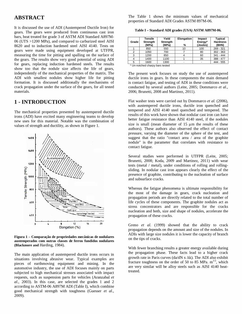
The mechanical properties presented by austempered ductile irons (ADI) have excited many engineering teams to develop new uses for this material. Notable was the combination of values of strength and ductility, as shown in Figure 1.
Figura 1 – Comparação de propriedades mecânicas de nodulares austemperados com outras classes de ferros fundidos nodulares (Blackmore and Harding, 1984).
The main application of austempered ductile irons occurs in situations involving abrasive wear. Typical examples are pieces of earthmoving equipment and mining. In the automotive industry, the use of ADI focuses mainly on parts subjected to high mechanical stresses associated with impact requests, such as suspension parts for vehicles (Aranzabal et al., 2003). In this case, are selected the grades 1 and 2 according to ASTM-06 A897M ADI (Table I), which combine good mechanical strength with toughness (Guesser et al., 2009).
The Table 1 shows the minimum values of mechanical properties of Standard ADI Grades ASTM 897M-06.
Table I – Standard ADI grades (USA) ASTM A897M-06.
Grade Tensile
Strength (MPa)
Yield Strength
(MPa)
Elongation
%
Impact Energy* (Joules)
Typical Hardness
(BHN) 1 850 550 10 100 269 - 321 2 1050 700 7 80 302 - 363 3 1200 850 4 60 341 - 444 4 1400 1100 1 35 388 - 477 5 1600 1300 - - 444 - 555
* Un-notched charpy bars tested
The present work focuses on study the use of austempered ductile irons in gears. In these components the main demand is contact fatigue, and testing of ADI in these conditions were conducted by several authors (Leite, 2005; Dommarco et al., 2006; Brunetti, 2008 and Martinez, 2011).
Flat washer tests were carried out by Dommarco et al. (2006), with austempered ductile irons, ductile iron quenched and tempered and AISI 4140 steel quenched and tempered. The results of this work have shown that nodular cast iron can have better fatigue resistance than AISI 4140 steel, if the nodules size is small (mean diameter of 15 m the results of these authors). These authors also observed the effect of contact pressure, varying the diameter of the sphere of the test, and suggest that the ratio "contact area / area of the graphite nodule" is the parameter that correlates with resistance to contact fatigue.
Several studies were performed in UTFPR (Leite, 2005; Brunetti, 2008; Koda, 2009 and Martinez, 2011) with wear tests (metal / metal), under conditions of rolling and rolling-sliding. In nodular cast iron appears clearly the effect of the presence of graphite, contributing to the nucleation of surface and subsurface cracks.
Whereas the fatigue phenomena is ultimate responsibility for the most of the damage in gears, crack nucleation and propagation periods are directly related to the total number of life cycles of these components. The graphite nodules act as stress concentrators and are responsible for the cracks nucleation and both, size and shape of nodules, accelerate the propagation of these cracks.
Greno et al. (1999) showed that the ability to crack propagation depends on the amount and size of the nodules. In ADIs with large size nodules it is lower the capacity of branch on the tips of cracks.
With fewer branching results a greater energy available during the propagation phase. These facts lead to a higher crack growth rate in Paris curves (da/dN x k). The ADI also exhibit fracture toughness on the order of 50 to 85 MPa. m1/2, which are very similar will be alloy steels such as AISI 4140 heat-treated.

The use of austempered ductile irons in gears has been the subject of several studies (Guedes et al., 2006 and Harding, 1984), aiming at the reduction of machining costs and noise in service. But its wider use in this application is caught up in technical and economic difficulties. For example, substitution of carburized steel by ADIs in gear subjected to severe applications, no technical advantages presents (as will also be seen in the experiments of this work) and, moreover, in the manufacture of gears is not normally economic take advantage offered by sand casting process, given the geometric simplicity of casting part that will result in the gear (machined).
Thus, this paper presents a new alternative for the production of gears, from nodular cast iron bars obtained by continuous casting. It is suggested to use gears in medium requests, usually produced in steels subjected to surface hardening.
2 - EXPERIMENTAL PROCEDURE
2.1 - MATERIALS
In this paper were used four materials to manufacture the spur gears: two alloy steels and two austempered ductile irons (ADI).
Table 1 – Treatment sequence performed on material gears.
SPUR MATERIAL HEAT and THERMOCHEMICAL TREATMENT
AISI 8620
Carburizing Temperature = 880 oC Time = 16 hours
Quenching Oil temperature = 130 oC
Tempering Temperature = 200 oC Time = 2 hours
AISI 4140 Surface Hardening
Induction hardening
Induction coil method
ADI 1 Austenitization Temperature = 890 oC
Time = 2 hours
Austempering Temperature = 290 oC Time = 2 hours (in salt bath)
ADI 2 Austenitization Temperature = 900 oC
Time = 2 hours
Austempering Temperature = 270 oC Time = 2 hours (in salt bath)
The gears were machined and submitted to heat and thermochemical treatment at Wiser, Pichler & Cia Ltda. The ADI materials were supply in round bars with diameter of 130 mm and length of 1880 mm. The process of foundry is continuous casting. The schematic sequence of such treatments is shown in Table 1.
The Table 2 shows the chemical composition of materials. The ADI composition was obtained by spectrometer and combustion chemical analysis and the data for the steels are the expected chemical composition.
Table 2 – Percent weight composition of ADI and alloy steels.
Materials C Mn Si Cr Mo Cu Mg
AISI 4140* 0.38–0.43 0.75–1.0 0.15–0.35 0.8–1.1 0.15–0.25 - -
AISI 8620* 0.18–0.23 0.70–0.9 0.15–0.35 0.4–0.6 0.15–0.25 - -
ADI 1 3.1 0.2 2.3 0.03 0.3 0.7 0.04
ADI 2 2.8 0.4 2.4 0.02 - 0.6 0.03 * standart chemical composition
The metallographic sample preparation was carried out by using standard techniques. Metallographic etching was performed employing 2% nital. Nodularity and nodule count values were measured by using both, the ASTM A 247 standard and the Image Pro Plus software. Worn surfaces and sub-surface were studied by using optical and scanning electron microscopes.
Figure 2 shows photomicrograph of pinion teeth of all materials after a chemical etching.
(a)
(b)
(c)
(d) Figure 2. Pinion photomicrograph: (a) AISI 8620, (b) AISI 4140,
(c) ADI 1 and (d) ADI 2.
The Table 3 shows the nodules characteristics of ductile irons.
Table 3 – Nodules characteristics of ADIs.
Form type
Nodularity (%)
Graphite area (%)
Nodule count (nod. / mm2)
ADI 1 VI 99 13 196
ADI 2 VI 98 13 532
In order to relate the mechanical properties with the results of fatigue tests of contact materials, mechanical tests were made with the purpose of obtaining hardness, tensile strength, elongation, elastic modulus and impact energy absorption. The characteristics of the mechanical tests were:

• Tensile tests according to DIN 50125, using a universal testing machine;
• Testing impact on charpy test piece for material ADI 2 and a AISI 4140, using a universal machine charpy impact;
• The Rockwell C hardness (HRc) was carried out in a machine Wolpert Hardness using a load of 150 kgf.
All equipment used in mechanical testing belongs to the Metallurgical and Mechanical Laboratory of Tupy SA. Table 4 summarizes the results obtained after mechanical tests.
Table 4 – Mechanical properties of spur gears materials.
Material Tensile
Strength (MPa)
Elongation (%)
Young Modulus
(GPa)
Hardness (HRc)
Charpy Energy
(Joules)
AISI 8620 1325* 12* 205* 58 --
AISI 4140 2040* 7,6* 205* 56 4,5
ADI 1 1546 2,1 -- 56 --
ADI 2 1273 3,5 186,9 54 5,8
* (Spur gears materials).
2.2 - CONTACT FATIGUE TESTS
For the contact fatigue tests was used a FZG-LASC tribometer. Figure 3 shows an overview of this equipment. This tribometer was designed, manufactured and assembled in the Contact and Surface Laboratory (LASC-UTFPR). By using the power recirculation principle, two pairs of gears can be tested at the same time. The load is imposed on the gears by applying torque on the shaft that the wheel is mounted on (FZG loads k6 and k9). A twist on the wheel axis is achieved by applying an eccentric load, using a lever and dead weight.
(a)
(b)
Figure 3. FZG gear test rig: (a) Picture and (b) schematic view.
To produce accelerated wear on the flank of gear teeth, it is common to use gears with modified profile. FZG type-C spur gears were used in the contact fatigue tests, and their characteristics are shown in Table 5.
Table 5 – Gear type C characteristics.
Parameter Unit. Pinion Wheel
Number of teeth – Z – 16 24
Module – m mm 4.5
Center Distance mm 91.5
Pressure angle – 20
Face width – b mm 14
Addendum modification – + 0.182 + 0.171
Addendum diameter mm 82.45 118.35
The gears used as samples were tested in the FZG-machine following a similar procedure proposed by the FZG Institute (FZG, 1992) for pitting testing. In this method, in addition to the geometrical characteristics of the gears, the loading forms for the running-in and pitting test stages are also presented. The loading stages are shown in Table 6.
Table 6 – Loading stages and speed used in contact fatigue tests.
FZG load Stage of test
Wheel speed (rpm)
Torque (N.m)
Contact pressure (MPa)
k6 running-in 1450 135.3 1153.8
k9 pitting 302.0 1723.8
Figure 4 shows the sequence of the methodology used in the contact fatigue experiments in gears. At the end of the tests, each gear (four pairs) was subjected to a 7.5 x 10⁶ -cycle (pinion) and 5.0 x 10⁶ -cycle (wheel) load.
Figure 4. Operating conditions used in the contact fatigue tests.

The Table 7 shows oil lubricant used in all contact fatigue tests.
Table 7 – ISO VG 100 characteristics in two temperatures.
Unit. Running-in Step Pitting Steps
Temperature oC 60 90
Kinematic viscosity –
m2/s (cSt)
39.9 x 10⁻⁶ (39.9)
14.6 x 10⁻⁶ (14.6)
Pressure-viscosity coefficient –
1/MPa (in2/lbf)
1.97 x 10⁻² (1.36 x 10⁻⁴)
1.62 x 10⁻² (1.12 x 10⁻⁴)
Specific mass – kg/m3 855.7 840.0
To determine roughness of the gear teeth, measurements were made on the teeth flank in the axial direction (parallel to the gear axis). Five teeth of each pinion and wheel were selected randomly. The tooth schematic figure in Table 8 shows the directions of roughness measurements.
Table 8 – Surface finish at the beginning of tests and after the running-in stage.
Materials Ra
(m) Rsm (mm)
Rvk (m)
AISI 8620 0,9 ± 0,1 0,04 ± 0,02 1,0 ± 0,2
AISI 4140 1,0 ± 0,4 0,15 ± 0,03 1,7 ± 1,0
ADI 1 0,8 ± 0,4 0,05 ± 0,03 1,4 ± 1,0
ADI 2 1,0 ± 0,1 0,05 ± 0,01 1,5 ± 0,4
2.3 - DAMAGED BY PITTING
Macroscopic images were taken from the gear teeth flank, showing the condition before running-in and after each step of the fatigue tests, so that the damage evolution in the flanks with the loading cycles could be observed. These images were used to quantify the pitting area. This procedure was done for all damaged teeth of each gear.
Figure 5 (a) shows an image of a pinion tooth flank where it is possible to identify two regions: (1) the effective contact area and (2) the lateral areas where there is no contact during mesh. Areas with pitting damage identified in Figure 8 (b) are measured using the Image Pro Plus software. The ratio of the damaged area and the effective contact area reports the percentage of damage on each tooth at each step of pitting test.
(a)
(b)
Figure 5. Images of AISI 8620 pinion tooth showing the surface aspect (a) before and (b) after pitting test.
The total damage of all the gear teeth was divided by the total active area of all flanks and, in this paper; the resulting value is called average damage percentage. Figure 6 shows an example of the damage count in a pinion tooth.
Figure 9. Example of count of damage area by pitting in a pinion tooth of an AISI 4140 gear.

The Weibull statistical distribution is widely used in studies of the wear phenomena The Weibull plot, as it became known, is an important tool for such studies. This graphic result of the statistical distribution of Weibull, relates the probability of failure of a component to the number of cycles it will be submitted and can be applied to the estimated periods of guarantee against failures made by mechanical equipment (Lipson and Sheth, 1973). For the study of fatigue, more precisely on the life of a component, which is the most usual implementation of this tool, the Weibull distribution is simplified to a distribution of two parameters (Lipson and Sheth, 1973).
For the fatigue tests of contact in gears were developed in this work charts for Weibull failure equivalent to 8% of the active area of the teeth.
3 - RESULTS
3.1 – WEAR RESISTANCE
The results of the total rate of damage (damaged area / number of cycles) for all the materials tested are shown in Figure 10. As might be expected, the AISI 8620 steel hardened, with higher surface hardness, has a greater wear resistance.
However, the hardness of tested materials, despite having a very good correlation with pitting resistance is not the only materials characteristic able to explain the results shown in Figure 10.
Figure 10. Damage rate for all materials tested.
Note that the ADI 2 shows similar values of damage resistance in relation to the induction hardened AISI 4140, which is a material traditionally used in gears. Table 4 shows that the absorbed energy in Charpy test is greater in ADI 2 that 4140, this result indicates that the ductile iron absorbs more energy at a fracture process.
This ability to retain the propagation of a crack is more related to the fracture toughness, which generally has higher values to ADI grade 3 (Greno et al., 1999).
Figure 11 shows a Weibull chart for all types of materials used in the manufacture of gears. This Weibull curve, the end of life has been standardized as 8% of the effective flanks area of the teeth with pitting damage.
Figure 11. Failure probability vs. load cycles for: (▲) ADI 1, () AISI 4140, () ADI 2 and () AISI 8620.
Once again it is observed that the behavior of pitting resistance is very similar between the ADI 2 and AISI 4140.
3.2 – ADI 1 versus ADI 2
Figures 10 and 11 show clearly that with the same chemical composition and heat treatment conditions very close, the ADI 2 showed much better suited to the gear application that ADI 1. Table 4 shows that the ADI 1 is a more rigid material, but with a reduced ability of strain before rupture.
However, the main difference between these materials is related to the size of graphite nodules. Figure 12 shows the micrograph of ADI 1 and 2 close to the surface of teeth flank.
Nodules of small size (ADI 2) lead to a higher local stress concentration parameter and to a formation of cracks from the nodes in shorter times. However, for the formation of pitting craters, beyond the period of cracks nucleation, the propagation stage is also very important.

(a)
(b)
Figure 12. Unetched microstructures of ADIs showing the differences in nodule count for: (a) ADI 1 - 196 (nod./mm2) and
(b) ADI 2 – 532 (nod./mm2).
Greno et al. (1999) show that ADI with higher amounts of nodules, the higher is the occurrence of a crack propagation mechanism referred to as "apparent crack branching mechanism". The occurrence of a higher branch in ADI 2 leads to the lower velocity of crack propagation and greater resistance to pitting formation.
Dommarco et al. (2006) in ADIs contact fatigue tests with three different sizes of nodules also found less pitting resistance for larger nodules. However, in this work the authors relate the nodules size with the contact area size, showing that the state of stress in contacts with smaller nodules is less severe.
3.3 – CRACK ANALYSIS
Figure 13 shows the form of cracks in the region of the gear pitch diameter tested.
Note that in the austempered ductile irons there is a greater amount of cracks, with branches and also cracks connected between the nodules. In the case of the steel gears, the depth of the crack is smaller and, in many cases, cracks arise in the surface of tooth gear. This contributes to the fact that the size of pitting be smaller, with a limited damage rate
(a)
(b)
(c)
(d)
Figure 13. Photomicrograph of gear in diametral pitch region show crack in surface and sub-surface. (a) ADI 1, (b) AISI 4140,
(c) ADI 2 and (d) AISI 8620.

4 - CONCLUSIONS
In contact fatigue tests with severe load, the carburized AISI 8320 steel proved more adequate than the austempered ductile iron, showing that the mechanical properties are critical in the resistance to damage in gear contact.
The austempered ductile iron with small nodule size showed to be very competitive with wear resistance similar to AISI 4140 steel induction hardened.
The results show that the nodule size affects the contact fatigue life independently of the ductile iron microstructure. The size and count of nodules affects both the nucleation and the propagation stage of cracks. ADI with minor nodules size has a greater wear resistance.
ACKNOWLEDGEMENTS
The authors would like to express their sincere gratitude to the support from National Scientific and Technological Development Council (CNPq Project 134251/2007-5), scholarship in the program PAE-REUNI and the companies: Wieser & Pichler Cia. Ltda and TUPY S.A.
REFERENCES
Aranzabal, J.; Serramoglia, G.; Goria, C.A.; Rousière, D., Development of a mixed (ferritic-ausferritic) ductile iron for automotive suspension parts. International Journal of Cast Metals Research, vol. 16, nº 1-3, pp. 185-190, 2003.
ASTM /A897M-06, Standard Specification for Austempered Ductile Iron Castings, 2006.
Blackmore P.A.; Harding, R.A., Journal of Heat Treating, vol. 3, number 4, pp.310-325, 1984.
Brunetti, C., Efeito da preparação de corpos de prova na vida em fadiga de contato de rolamento de ferro fundido nodular austemperado; Dissertação de mestrado, PPGEM, Univeridade Tecnológica Federal do Paraná UTFPR, 2008.
Dommarco, R C; Jaureguiberry, A J; Sikora, J A., Rolling contact fatigue resistance of ductile iron with different nodule counts and matrix microstructures. Wear, 261, pp. 172-179, 2006.
Greno, G.L., Otegui, J.L., Boeri, R.E., Mechanisms of fatigue crack growth in ADI. International Journal of Fatigue, 21, pp. 35-43, 1999.
Guedes, L.C.; Guesser, W.L.; Duran, P.V.; Santos S.B.A., Utilização de ferros fundidos nodulares bainíticos na fabricação de engrenagens. Metalurgia ABM, v. 42, n. 341, pp. 237, 1986.
Guesser, W. L; Franco, E; Lussoli, C; Costa, C. E., Ferro nodular austemperado a partir da zona crítica, 14° Congresso de Fundição ABIFA - CONAF – São Paulo, 2009.
Harding, R. A., “Establishing gear-testing at BCIRA to promote the use of austempered nodular iron in engineering and automotive applications”, 1984.
Koda, F., Estudo da Fadiga de Contado em Engrenagens Cilíndricas de Dentes Retos, Dissertação de mestrado, PPGEM, Universidade Tecnológica Federal do Paraná, 2009.
Leite, M. V., Análise dos mecanismos de desgaste por fadiga de contato, Dissertação de mestrado, PPGEM, Universidade Tecnológica Federal do Paraná, UTFPR, 2005.
Lipson, C.; Sheth, N. J., Statistical Design and Analysis of Engineering Experiments. McGraw-Hill, pp. 36-44, 1973.
Martinez, J. A. B., Comparação da resistência ao desgaste por fadiga de contato de engrenagens fabricadas em aço AISI 4140 e ferro fundido nodular austemperdo; Dissertação de mestrado, PPGEM, Universidade Tecnológica Federal do Paraná, 2011.
CONTACT INFORMATION
Carlos Henrique da Silva Federal University of Technology – Paraná (UTFPR) Av. 7 de Setembro, 3165, Curitiba – Paraná – Brazil Tel/fax: + 55 41 3310-4663 Zipcode: 80230-901 [email protected]