attachment 7 lr-no6-0418 lcr h05-01, rev. i calculation no. h-1-cg-mdc … · 2012-11-21 ·...
TRANSCRIPT

Attachment 7 LR-NO6-0418LCR H05-01, Rev. I
Calculation No. H-1-CG-MDC-1795, Revision 4,Control Rod Drop Accident Radiological Consequences
NC.DE-AP.ZZ-01302(Q)
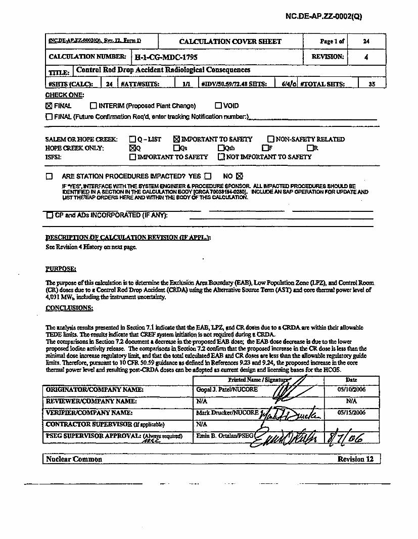
ffC.DE4-PY. 2(O). Rev. 12. Form 11 CALCULATION COVER SHEET Page I of 24
CALCULATION NUMBER: H-1-CG-MDC-1795 REVISION: 4
Tri'L: I Control Rod Drop Accident Radiological Consequences
NSJWS ICALQ 1 24 1#AITI#SHT: I1n IIDWVlSO.59t7Z48 SMT: 104161 #TOTAL SERTS: 3
CHECK ONE:
0 FINAL ] INTERIM (Proposed Plant Change) OVOID
o FINAL (Future Confirmation Req'd, enter tracking Notification number:.)___
sAL•E•M • oPE CREEK: 0 Q- uST 0 IMPORTANTT• SAFETY 0 NON-SAFETY RELATED
HOPE CREEK ONLY: NQ 0Qs OQs [IF ORISFSl: 0 IMPORTANT TO SAFETY 0 NOT IMPOkTANT TO SAFETY
O ARE STATION PROCEDURES IMPACTED? YES [ NO IDIF YES'.INTERFACE WITH THE SYSTEM ENGINEER & PROCEDURE SPONSOR. ALL IMPACTED PROCEDURES SHOULD BEIDENTIFE%).IN A SECTION IN THE cALC.mJATION BODY cRCA70038194o02801. INCLUDE AN SP OPERATION FOR UPDATE AND.ISTTHE3SAP ORDERS HERE AND WtMIfN THE BODY-OFTUS CALCULATION.
[0 CP and ADs INCORPORATED (IF ANY); ..... _ __'
JDESQRn'TON,O• &•AA•-JTM REMv ON AFMAr•
See Revision 4 Ilt"r olineic page.
PRPMOSE:
The purpose ofthis calculation is to determine the Exclusion AraR Boundary (EAB), LowPopulation Zone "LZ), and Control Room.(CR) doses due to a Control Rod Drop Accident (CRDA) us•ng the Altrnative Source Term (AST) and core thermal power level of4.031 MW(, mddg1crany-CONCLUSIONS:
The analysis results presented in Section 7.1 indicatetha the EAB,LPZ,ý ad CR doses due to aCDA are within their allowableTEDE Emits. The tesults indicate that CREF system Initiation is not required during a CRDA-.The comparisons in Section 72 document adecrea. i the proposed EAB dose; the EXB dose decrease is dueto the lowerproposed Iodine activity release. The comparisons in Section72 confirmthat the proposed increase in the CR dose is less than theminimal dose increase regulatory limit, and that the total calculated EA and CR doses are less than the allowable regulatory guideimits. Therefore, pursuant to 10 CFR 50.50 guidance ps defined in 1Aeferen•es 923 and 9.24, the proposed increase in the corethermal power level and resulting post-CRDA doses can be adopted as Current design and licensrng bases for the HCGS.
I Nuclear Common Revision 12 1I Nula omn eiin1
CALCULATION CONTINUATION SHEET SHEET 2 of 24
CALC.NO.: H-1-CG-MDC-1795 REFERENCE:
G. Patel/NUCORE,ORIGINATOR, DATE REV: 05/10/2006 4
M. Drucker/NUCORE,REVIEWER/VERIFIER, DATE 05/15/2006
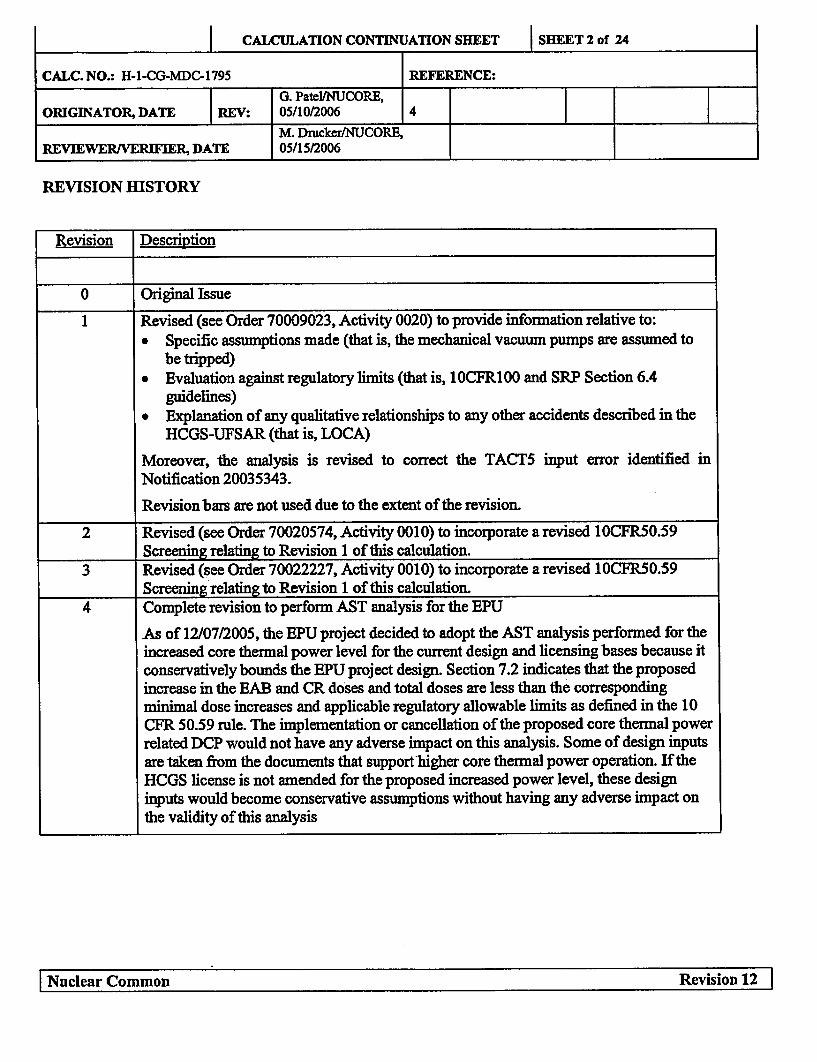
REVISION HISTORY
Revision Description
0 Original Issue
1 Revised (see Order 70009023, Activity 0020) to provide information relative to:" Specific assumptions made (that is, the mechanical vacuum pumps are assumed to
be tripped)" Evaluation against regulatory limits (that is, 1OCFR100 and SRP Section 6.4
guidelines)" Explanation of any qualitative relationships to any other accidents described in the
HCGS-UFSAR (that is, LOCA)
Moreover, the analysis is revised to correct the TACT5 input error identified inNotification 20035343.
Revision bars are not used due to the extent of the revision.
2 Revised (see Order 70020574, Activity 0010) to incorporate a revised 10CFR50.59Screening relating to Revision 1 of this calculation.
3 Revised (see Order 70022227, Activity 0010) to incorporate a revised 10CFR50.59Screening relating to Revision 1 of this calculation.
4 Complete revision to perform AST analysis for the EPU
As of 12/07/2005, the EPU project decided to adopt the AST analysis performed for theincreased core thermal power level for the current design and licensing bases because itconservatively bounds the EPU project design. Section 7.2 indicates that the proposedincrease in the EAB and CR doses and total doses are less than the correspondingminimal dose increases and applicable regulatory allowable limits as defined in the 10CFR 50.59 rule. The implementation or cancellation of the proposed core thermal powerrelated DCP would not have any adverse impact on this analysis. Some of design inputsare taken from the documents that support'higher core thermal power operation. If theHCGS license is not amended for the proposed increased power level, these designinputs would become conservative assumptions without having any adverse impact onthe validity of this analysis
I Nuclear Common Revision 12 1I Nuclear Common Revision 12 I
CALCULATION CONTINUATION SHEET SHEET 3 of 24
CALC. NO.: H-1-CG-MDC-1795 REFERENCE:
G. PateIINUCORE,ORIGINATOR, DATE REV: 05/10/2006 4
M. Drucker/NUCORE,REVIEWERNVERIFIER, DATE 05/15/2006
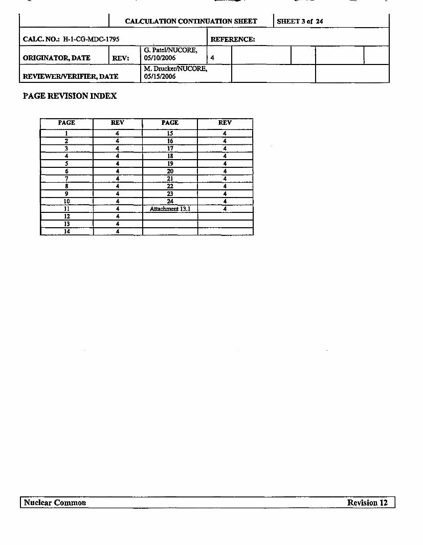
PAGE REVISION INDEX
PAGE REV PAGE REV
1 4 15 42 4 16 43 4 17 44 4 18 45 4 19 46 4 20 47 4 21 48 4 22 49 4 23 410 4 24 411 4 Attachment 13.1 412 413 414 4
I Nula omn eiin1
I Nuclear Common Revision 12

CALCULATION CONTINUATION SHEET SHEET 4 of 24
CALC. NO.: H-1-CG-MDC-1795 REFERENCE:
G. Patel/NUCORE,ORIGINATOR, DATE REV: 05/1042006 4
M. Drucker/NUCORE,REVIEWER/VERIFIER, DATE 05/1512006
TABLE OF CONTENTS
Section Sheet No.
Cover Sheet 1
Revision History 2
Page Revision Index 3
Table of Contents 4
1.0 Purpose 5
2.0 Background 5
3.0 Analytical Approach 5
4.0 Assumptions 8
5.0 Design Inputs 11
6.0 Calculations 16
7.0 Results Summary 17
8.0 Conclusions 18
9.0 References 18
10.0 Tables 20
11.0 Figures 22
12.0 Affected Documents 24
13.0 Attachments 24
I Nuclear Common Revision 12 1I Nula omnRvso 2I

CALCULATION CONTINUATION SHEET SHEET S of 24
CALC. NO.: H-I-CG-MDC-1795 REFERENCE:
G. Patel/NUCORE,ORIGINATOR, DATE REV: 05/10/2006 4
M. Dnicker/NUCORE,REVIEWER/ERIFIER, DATE 05/15/2006
1.0 PURPOSE:
The purpose of this calculation is to determine the Exclusion Area Boundary (EAB), Low Population Zone(LPZ), and Control Room (CR) doses due to a Control Rod Drop Accident (CRDA) using the AlternativeSource Term (AST) and core thermal power level of 4,031 MWt, including the instrument uncertainty.
2.0 BACKGROUND:
Hope Creek Technical Specification (TS) LIMITING CONDITION FOR OPERATION (LCO) 3/4.3.10requires that two channels of the main steam line radiation - high, high function for the mechanical vacuumpump (MVP) trip shall be operable. This LCO 3/4.3.10 assures that the post-CRDA fission product release pathto the environment would be through the main condenser.
The MVP trip is required to be OPERABLE in OPERATIONAL CONDITIONS 1 and 2 when any mechanicalvacuum pump is in service (i.e., taldng a suction on the main condenser) and any main steam line is not isolated,to mitigate the consequences of a postulated CRDA. In this condition fission products released during a CRDAcould be discharged directly to the environment. Therefore, the MVP trip is necessary to assure conformancewith this calculation's assumption that the post-CRDA radiological release path is via the condenser. InOPERATIONAL CONDITION 3, 4 or 5, the consequences of a CRDA are insignificant, and are not expectedto result in any fuel damage or fission product releases. When the MVP is not in service or the main steam linesare isolated, fission product releases via the MVP pathway would not occur.
The function of MVP is to evacuate the condenser during startup. Operating Procedure HC.OP-SO.CG-0001(Q) (Ref. 9.11) includes Precaution 3.1.2, which identifies that operation of the mechanical vacuum pumpswhile radioactive steam is being admitted to the main condenser will result in high radiation levels at the southplant vent. The procedure also includes Limitation 3.2.4, which calls for securing the mechanical vacuumpumps from service and placing the steam jet air ejectors (SJAE) in service prior to reactor power exceeding5%. The expected MVP response following a CRDA is to be automatically tripped due to either loss of offsitepower or a main steam radiation monitor signal (Ref 9.13). The post-CRDA activity release through the MVPduring startup will be insignificant due to the MVP operation limited to 5% core power. For the post-CRDArelease through the Gaseous Waste Management System (GWMS) including the SJAE, all of the iodine thatenters the off-gas treatment system is retained indefinitely and does not contribute to the CR and off-site dose(Ref. 9.12, page 3). Therefore, the post-CRDA dose impact for the releases through the MVP during the startupat a low power level and GWMS during normal operation at a rated power level will be bounded by the post-CRDA release through the isolated condenser, which is analyzed in the following section.
3.0 ANALYTICAL APPROACH:
This analysis uses Version 3.02 of the RADTRAD computer code to calculate the potential radiologicalconsequences of the CRDA. The RADTRAD code was developed by Sandia National Laboratories, the NRC'stechnical contractor, for the staff to use in establishing fission product transport and removal models and inestimating radiological doses at selected receptors at nuclear power plants. The RADTRAD code is documented
I Nuclear Common Revision 12 1II Nuclear Common Revision 12 I

CALCULATION CONTINUATION SHEET SHEET 6 of 24
CALC. NO.: H-1-CG-MDC-1795 REFERENCE:G. Patel/NUCORE,
ORIGINATOR, DATE REV: 05/10/2006 4
M. Drucker/NUCORE,REVIEWER/VERIFIER, DATE 05/15/2006
in NUREG/CR-6604 (Ref. 9.2). The RADTRAD code is maintained as Software ID Number A-0-ZZ-MCS-0225 (Ref. 9.15).
The consequences of a CRDA are analyzed using the as-built plant specific as-built design and licensingbasesinputs, which are compatible to the AST and TEDE dose criteria. There is no specific ESF function credited inthe analysis.
For the CRD accident, the release from the breached fuel is based on an NRC approved fuel vendormethodology for the number of fuel rods breached and the assumption that 10% of the core inventory of noblegases and iodine, and 12% of the core inventory of alkali metals are in the fuel gaps. The release attributed tofuel melting is based on the fraction of the fuel that reaches or exceeds the initiation temperature for fuelmelting and on the assumption that 100% of the noble gases and 50% of the iodines contained in that fractionare released to the reactor coolant. The activities released from the fuel gaps and melted fuel are assumed to beinstantaneously mixed in the reactor coolant within the pressure vessel. Of the activity released to the reactorcoolant, 100% of the noble gases, 10% of the iodine, and 1% of the remaining radionuclides are assumed toreach the turbine and condenser. Of the activity that reaches the turbine and condenser, 100% of the noblegases, 10% of the iodine, and 1% of the remaining radionuclides are available for release to the environment.The turbine and condenser leak to the atmosphere as a ground-level release at a rate of 1% per day for a periodof 24 hours, at which time the condenser leakage is assumed to terminate. No credit is taken for dilution orholdup within the turbine building. The post-CRDA activity from the turbine and condenser can be released tothe turbine building (TB) and to the environment at ground level through the south plant vent when offsitepower is available; and through the TB louvers/TB vent during a loss of offsite power (Refs. 9.16 & 9.17). The
X/Qs for these release paths are obtained from Reference 9.5, Section 8.0, and listed in the following table:
HCGS Control RoomTime 95% Atmospheric Dispersion Factors (X/Qs) (s/mr)
Interval South Plant TB Louvers TB Vent(hr) Vent (s/m3) (s/m3)0-2 5.75E-04 6.17E-04 3.48E-042-8 3.84E-04 4.OOE-04 2.55E-04
8-24 1.40E-04 1.44E-04 9.1 lE-0524-96 9.08E-04 1.00E-04 5.37E-05
96-720 7.01E-04 7.49E-05 3.82E-05
Comparison of X/Qs in the above table indicates that the TB louvers release path is the most limiting releasepath for the 0 to 24 hour post-CRDA release prior to the condenser leakage being terminated. Therefore, the CRdose is calculated using the post-CRDA release through the TB louvers. The Control Room EmergencyFiltration (CREF) system is not credited in the analysis. The CR is assumed to operate in a normal mode ofoperation with a normal HVAC inflow rate of 3,300 cfin (3,000 cfm + 10 % uncertainty) for the entire durationof the accident. The resulting doses at the EAB, LPZ, and CR locations are compared with the dose acceptancecriteria in Section 7.0.
I Nuclear Common Revision 12 1
I Nuclear Common Revision 12 I

CALCULATION CONTINUATION SHEET SHEET 7 of 24
CALC. NO.: H-1-CG-MDC-1795 REFERENCE:
G. Patel/NUCORE,ORIGINATOR, DATE REV: 05/10/2006 4
M. Drucker/NUCORE,REVIEWERNVERIFIER, DATE 05/15/2006
The core activity inventory is obtained from Reference 9.3, which is calculated based on a thermal power levelof 4,031 MWt. A radial peaking factor of 1.75 is conservatively used instead of the 1.5 value recommended inReference 9.6. The isotopic activity available for release from the condenser are calculated in Tables 1 & 2based on the core activity inventory obtained from Reference 9.3 and the CRDA failed and melted fuel fractionsfrom Reference 9.12 (Section 6.2.2).
The RADTRAD V3.02 (Ref 9.2 & 9.15) default nuclide inventory file (NIF) Bwr def. NIP is modified basedon the isotopic activities calculated in Table 2. The newly developed plant-specific nuclide inventory file(HEPUCRDA_def.txt) is further modified to include Kr-83m, Xe-13lm, Xe-133m, Xe-135m, Xe-138, Rb-88,and Cs-138 isotopes. The RADTRAD3.02 dose conversion factor (DCF) File (Fgrl 1&12) is modified toinclude the DCFs obtained from References 9.7 & 9.8 for the added noble gas isotopes. The modified DCF fileHCRDAFG1I&12.txt is used in the CRDA analysis. The newly developed release fraction and timing file(HCRDARFT.txt) is used to postulate an instantaneous post-CRDA release. The NIP is developed based onthe actual activity in curies released to the environment from the condenser; therefore, the thermal power levelis set to unity in the RADTRAD input.
Determine Compliance of Increased Dose Consequences With 10CFR50.59 Guidance
Consistent with the RG 1.183, Section 1.1.1, once the initial AST implementation has been approved by thestaff and has become part of the facility design basis, the licensee may use 10 CFR 50.59 and its supportingguidance in assessing safety margins related to subsequent facility modifications and changes to procedures.The NRC Safety Evaluation Report for Amendment 134 (Ref. 9.26) approved the AST for the HCGS licensingbasis analyses.
An increase in control room, EAB or LPZ dose consequence is considered acceptable under the 10 CFR 50.59rule if the magnitude of the increase is minimal (as defined by the guidance in Refs. 9.23 and 9.24), and if thetotal calculated dose is less than the allowable regulatory guide 1.183 dose limit. The current licensing basisanalysis is documented in the calculation H-1-CG-MDC-1975, Rev 3. The increases in the proposed EAB andCR doses are compared with the 10 CFR 50.59 allowable minimal dose increases in Section 7.2. Similarly, theproposed calculated total doses are compared with the allowable regulatory guide dose limits. The comparisonsin Sections 7.2 confirm that the proposed increases in the EAB & CR doses and the total calculated doses areless than the corresponding minimal dose increases and allowable regulatory guide limits. Therefore, pursuantto 10 CFR 50.59 guidance as defined in References 9.23 and 9.24, the proposed increase in the core thermalpower level and resulting post-CRDA doses can be adopted as current design and licensing bases for the HCGS.
I Nuclear Common Revision 12 1I Nuclear Common
Revision 12 I
CALCULATION CONTINUATION SHEET SHEET 8 of 24
CALC. NO.: H-1-CG-MDC-1795 REFERENCE:
G. Patel/NUCORE,ORIGINATOR, DATE REV: 05/10/2006 4
M. Drucker/NUCORE,REVIEWERJVERIFIER, DATE 05/15/2006
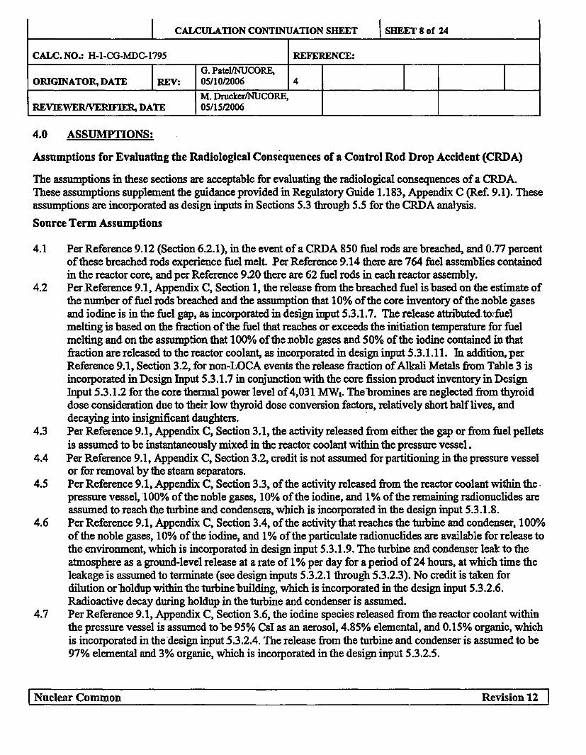
4.0 ASSUMPTIONS:
Assumptions for Evaluating the Radiological Consequences of a Control Rod Drop Accident (CRDA)
The assumptions in these sections are acceptable for evaluating the radiological consequences of a CRDA.These assumptions supplement the guidance provided in Regulatory Guide 1.183, Appendix C (Ref. 9.1). Theseassumptions are incorporated as design inputs in Sections 5.3 through 5.5 for the CRDA analysis.
Source Term Assumptions
4.1 Per Reference 9.12 (Section 6.2.1), in the event of a CRDA 850 fuel rods are breached, and 0.77 percentof these breached rods experience fuel melt. Per Reference 9.14 there are 764 fuel assemblies containedin the reactor core, and per Reference 9.20 there are 62 fuel rods in each reactor assembly.
4.2 Per Reference 9.1, Appendix C, Section 1, the release from the breached fuel is based on the estimate ofthe number of fuel rods breached and the assumption that 10% of the core inventory of the noble gasesand iodine is in the fuel gap, as incorporated in design input 5.3.1.7. The release attributed toWfuelmelting is based on the fraction of the fuel that reaches or exceeds the initiation temperature for fuelmelting and on the assumption that 100% of the noble gases and 50% of the iodine contained in thatfraction are released to the reactor coolant, as incorporated in design input 5.3.1.11. In additionperReference 9.1, Section 3.2, for non-LOCA events the release fraction of Alkali Metals from Table 3 isincorporated in Design Input 5.3.1.7 in conjunction with the core fission product inventory in DesignInput 5.3.1.2 for the core thermal power level of 4,031 MWt. The-bromines are neglected from thyroiddose consideration due to their low thyroid dose conversion factors, relatively short half lives, anddecaying into insignificant daughters.
4.3 Per Reference 9.1, Appendix C, Section 3.1, the activity released from either the gap or from fuel pelletsis assumed to be instantaneously mixed in the reactor coolant within the pressure vessel.
4.4 Per Reference 9.1, Appendix C, Section 3.2, credit is not assumed for partitioning in the pressure vesselor for removal by the steam separators.
4.5 Per Reference 9.1, Appendix C, Section 3.3, of the activity released from the reactor coolant within the.pressure vessel, 100% of the noble gases, 10% of the iodine, and 1% of the remaining radionuclides areassumed to reach the turbine and condensers, which is incorporated in the design input 5.3.1.8.
4.6 Per Reference 9.1, Appendix C, Section 3.4, of the activity that reaches the turbine and condenser, 100%of the noble gases, 10% of the iodine, and 1% of the particulate radionuclides are available for release tothe environment, which is incorporated in design input 5.3.1.9. The turbine and condenser leak to theatmosphere as a ground-level release at a rate of 1% per day for a period of 24 hours, at which time theleakage is assumed to terminate (see design inputs 5.3.2.1 through 5.3.2.3). No credit is taken fordilution or holdup within the turbine building, which is incorporated in the design input 5.3.2.6.Radioactive decay during holdup in the turbine and condenser is assumed.
4.7 Per Reference 9.1, Appendix C, Section 3.6, the iodine species released from the reactor coolant withinthe pressure vessel is assumed tobe 95% CsI as an aerosol, 4.85% elemental, and 0.15% organic, whichis incorporated in the design input 5.3.2.4. The release from the turbine and condenser is assumed to be97% elemental and 3% organic, which is incorporated in the design input 5.3.2.5.
Nuclear Common Revision 12

CALCULATION CONTINUATION SHEET SHEET 9 of 24
CALC. NO.: H-1-CG-MDC-1795 REFERENCE:
G. Patel/NUCORE,ORIGINATOR, DATE REV: 05/10/2006 4
M. Drucker/NUCORE,REVIEWER/VERIFIER, DATE 05/15/2006
Offsite Dose Consequences:
The following guidance is used in determining the TEDE for a maximum exposed individual at EAB and LPZlocations:
4.9 The maximum EAB TEDE for any two-hour period following the start of the radioactivity release isdetermined (Ref. 9.1, Section 4.1.5), and used in determining compliance with the dose acceptancecriteria in Reference 9.1, Section 4.4, Table 6:
EAB Dose Acceptance Criterion: 6.3 Rem TEDE
4.10 The breathing rates for persons at offsite locations are given in Reference 9.1, Section 4.1.3, and are
incorporated in Design Input 5.3.4.
4.11 The maximum Low Population Zone (LPZ) TEDE is determined for the most limiting receptor at theouter boundary of the LPZ (Ref. 9.1, Section 4.1.6), and used in determining compliance with the dosecriteria in Reference 9.1, Section 4.4 Table 6:
LPZ Dose Acceptance Criterion: 6.3 Rem TEDE
4.12 No correction is made for depletion of the effluent plume by deposition on the ground (Ref 9.1, Section4.1.7).
Control Room Dose Consequences
The following guidance is used in determining the TEDE for maximum exposed individuals located in the
control room:
4.13 The CR TEDE analysis considers the following sources of radiation that will cause exposure to control
room personnel (Ref 9.1, Section 4.2.1):
* Contamination of the control room atmosphere by the intake or infiltration (i.e., filtered CRventilation inflow via the CR air intake, and unfiltered inleakage) of the radioactive materialcontained in the post-accident radioactive plume released from the facility,
* Contamination of the control room atmosphere by the intake or infiltration (i.e., filtered CRventilation inflow via the CR air intake, and unfiltered inleakage) of airborne radioactive materialfrom areas and structures adjacent to the control room envelope,
* Radiation shine from the external radioactive plume released from the facility (i.e., externalairborne cloud),
* Radiation shine from radioactive material in the reactor containment (i.e., containment shine dose;not applicable to a CRDA release occurring outside containment),
I Nuclear Common Revision 12

CALCULATION CONTINUATION SHEET SHEET 10 of 24
CALC. NO.: H-1-CG-MDC-1795 REFERENCE:
G. Patel/NUCORE,ORIGINATOR, DATE REV: 05/10/2006 4
M. Drucker/NUCORE,REVIEWER/VERIFIER, DATE 05/15/2006
Radiation shine from radioactive material in systems and components inside or external to thecontrol room envelope, e.g., radioactive material buildup in recirculation filters (i.e., CR filtershine dose).
Note: The external airborne cloud shine dose and CR filter shine dose due to a CRDA are insignificantcompared to those due to a LOCA (see the core release fractions for LOCA and non-LOCAdesign basis accidents in Tables 1 and 3 of Reference 9.1). Therefore, these direct dosecontributions are considered to be insignificant and are not evaluated for a CRDA.
4.14 The radioactive material releases and radiation levels used in the control room dose analysis aredetermined using the same source term, transport, and release assumptions used for determining theexclusion area boundary (EAB) and the low population zone (LPZ) TEDE values (Ref 9.1, Section4.2.2).
4.15 The occupancy and breathing rate of the maximum exposed individual presents in the control room areincorporated in design input 5.3.3 (Ref. 9.1, Section 4.2.6).
4.16 10 CFR 50.67 (Ref 9.4) establishes the following radiological criterion for the control room.
CR Dose Acceptance Criterion: 5 Rem TEDE (50.67(b)(2)(iii))
4.17 Although allowed by Reference 9.1, Section 4.2.4, credit is not taken for the engineered safety featuresof the CR emergency filtration (CREF) system that mitigate airborne activity within the control room.
4.18 No credits for KI pills or respirators are taken (Ref. 9.1, Section 4.2.5).
I Nuclear Common Revision 12 I
I Nuclear Common Revision 12

CALCULATION CONTINUATION SHEET SHEET 11 of 24
CALC. NO.: H-1-CG-MDC-1795 REFERENCE:
G. Patel/NUCORE,ORIGINATOR, DATE REV: 05/10/2006 4
M. Drucker/NUCORE,REVIEWER/VERIFIER, DATE 05/15/2006
5.0 DESIGN INPUTS:
5.1 General Considerations
5.1.1 Applicability of Prior Licensing Basis
The implementation of an AST is a significant change to the design basis of the facility and assumptions and
design inputs used in the analyses. The characteristics of the ASTs and the revised TEDE dose calculation
methodology may be incompatible with many of the analysis assumptions and methods currently used in the
facility's design basis analyses. The HCGS plant specific design inputs and assumptions used in the current
TID-14844 analyses were assessed for their validity to represent the as-built condition of the plant and
evaluated for their compatibility to meet the AST and TEDE methodology. The analysis in this calculation
ensures that analysis assumptions, design inputs, and methods are compatible with the ASTs and the TEDE
criteria.
5.1.2 Credit for Engineered Safety Features
Credit is taken only for accident mitigation features that are classified as safety-related, are required to be
operable by technical specifications, are powered by emergency power sources, and are either automatically
actuated or, in limited cases, have actuation requirements explicitly addressed in emergency operating
procedures. The safety-related CR emergency filtration system is not credited for dose mitigation.
5.1.3 Assignment of Numeric Input Values
The numeric values that are chosen as inputs to the analyses required by 10 CFR 50.67 (Ref. 9.4) are
compatible to AST and TEDE dose criteria and selected with the objective of producing conservative
radiological consequences. As a conservative alternative, the limiting value applicable to each portion of the
analysis is used in the evaluation of that portion.
5.1.5 Meteorology Considerations
The control room atmospheric dispersion factors (X/Qs) for the turbine building louver release point are
developed (Ref. 9.5) using the NRC sponsored computer code ARCON96. The EAB and LPZ X/Qs were
I Nuclear Common Revision 12 1I Nuclear Common
Revision 12 I

CALCULATION CONTINUATION SHEET SHEET 12 of 24
CALC. NO.: H-1-CG-MDC-1795 REFERENCE:
G. Patel/NUCORE,ORIGINATOR, DATE REV: 05/10/2006 4
M. Drucker/NUCORE,REVIEWER/VERIFIER, DATE 05/15/2006
reconstituted using the HCGS plant specific meteorology and appropriate regulatory guidance. The off-site x/Qs
reconstituted in Reference 9.9 were accepted by the staff in previous licensing proceedings.
5.2 Accident-Specific Design Inputs/Assumptions
The design inputs/assumptions utilized in the EAB, LPZ, and CR habitability analyses are listed in the
following sections. The design inputs are compatible with the AST and TEDE dose criteria and assumptions are
consistent with those identified in Appendix C of RG 1.183 (Ref. 9.1). The design inputs and assumptions in the
following sections represent the as-built design of the plant.
I Nuclear Common Revision 12 I
I 'Nuclear Common Revision 12I

I CALCULATION CONTINUATION SHEET ISHEET 13 of 24
CALC. NO.: H-1-CG-MDC-1795 REFERENCE:
G. Patel/NUCORE,ORIGINATOR, DATE REV: 05/10/2006 4
M. Drucker/NUCORE,REVIEWER/VERIFIER, DATE 05/15/2006
Design Input Parameter Value Assigned Reference
5.3 CRDA Parameters5.3.1 Source Term5.3.1.1 Proposed extended power 4,031 MWt Section 6.1uprate level 15.3.1.2 Isotopic Core Inventory In Ci/MWt 9.3
Isotope Activity Isotope Activity Isotope ActivityKR-83M 2.981E+03 1-134 5.937E+04 RB-86 1.300E+02KR-85 4.711E+02 1-135 5.117E+04 RB-88 1.574E+04
KR-85M 5.908E+03 XE-131M 3.129E+02 CS-134 1.319E+04KR-87 1.097E+04 XE-133 5.306E+04 CS-136 3.704E+03KR-88 1.539E+04 XE-133M 1.743E+03 CS-137* 1.096E+041-131 2.779E+04 XE-135 1.482E+041-132 3.991E+04 XE-135M 1.118E+04 * CS-137 inventory includes BA-1-133 5.454E+04 XE-138 4.322E+04 137M inventory
5.3.1.3 Radionuclide CompositionGroup Elements 9.1, Section 3.4, Table 5
Noble gases Xe, KrHalogens I, Br
Alkali metals Cs,Rb5.3.1.4 Number of fuel rods in 62 9.20fuel assembly5.3.1.5 Damaged fuel rods:
Breached Fuel Rods 850 9.12, Section 6.2.2Melted Fuel Rods 0.77% of the breached fuel rods
5.3.1.6 Number of fuel assemblies 764 9.14in core5.3.1.7 Fission products release 10% noble gas in breached rods 9.1, Appendix C, Section 1from breached fuel rods to reactor 10% iodine in breached rods 9.1, Appendix C, Section 1coolant 12% Alkali metal inbreached 9.1, Section 3.2, Table 3
rods5.3.1.8 Fission products transfer 100% noble gas 9.1, Appendix C, Section 3.3from reactor coolant to turbine/ 10% iodinecondenser 1% Alkali metal5.3.1.9 Fission products available 100% noble gas 9.1, Appendix C, Section 3.4for release to the environment 10% iodinefrom turbine/ condenser 1% Alkali metal5.3.1.10 Radial peaking factor 1.5 9.6, Appendix A, Section 111.7
(1.75 conservatively assumed)
Nuclear Common Revision 12

CALCULATION CONTINUATION SHEET
Design Input Parameter Value Assigned Reference5.3.1.11 Fission products release 100% noble gas in melted fuel 9.1, Appendix C, Section 1from melted fuel rods to reactor 10% iodine in melted fuel 9.1, Appendix C, Section 1coolant 25% Alkali metal in melted fuel Assumed based on 9.1, Table 15.3.2 Activity Transport in Turbine Building (see Figure 1)5.3.2.1 Condenser leak rate 1% per day 9 .1, Appendix C, Section 3.45.3.2.2 Duration of 24 hours 9.1, Table 6 and Appendix C,turbine/condenser leak rate Section 3.45.3.2.3 Turbine/Condenser leak to Ground level release 9.1, Appendix C, Section 3.4the atmosphere 1I15.3.2.4 Chemical form of Iodine in reactor coolant released within the pressure vessel
Aerosol 95% 9.1, Appendix C, Section 3.6Elemental 4.85%
Organic 0.15%5.3.2.5 Chemical form of iodine available for release from turbine and main condenser
Elemental 97% 9.1, Appendix C, Section 3.6
Organic 3% _5.3.2.6 Dilution or holdup within Not credited 9.1, Appendix C, Section 3.4the turbine building5.3.2.7 Condenser free volume 235,000 t3 9.13, Page 3
5.3.3 Control Room Parameters (see Figure 2)5.3.3.1 CR volume 85,000 fW3 9.10, page 105.3.3.2 CR normal air inflow rate 3,000 ± 10% cfru for 0-720 hrs 9.18 and Assumption 4.17during CRDA (conservatively modeled as
3,300 cfin)5.3.3.3 CR occupancy factors
Time (Hr) % 9.1, Section 4.2.60-24 100
24-96 6096-720 40
5.3.3.4 CR breathing rate 3.5E-04 m3/sec 9.1, Section 4.2.65.3.3.5 CR atmospheric dispersion factors for Turbine Building louvers release (X/Qs)
Time (Hr) X/Q (secim)0-2 6.17E-04 9.5, Section 8.32-8 4.OOE-048-24 1.44E-04
24-96 1.OOE-0496-720 7.49E-05
Nuclear Common Revision 12

I CALCULATION CONTINUATION SHEET I SHEET 15 of 24
CALC. NO.: H-1-CG-MDC-1795 REFERENCE:
G. Patel/NUCORE,ORIGINATOR, DATE REV: 05/10/2006 4
M. Drucker/NUCORE,REVIEWER/VERIFIER, DATE 05/15/2006
Design Input Parameter Value Assigned Reference5.3.4 Site Boundary Release Model Parameters
5.3.4.1 EAB atmospheric J 1.9E-04 (see/n) 9.9, Pages 5 &.9dispersion factor (X/Q) I5.3.4.2 LPZ Atmospheric dispersion factors (XIQs)
Time (Hr) X/Q (sec/mr)0-2 1.9E-05 9.9, Pages 5 & 92-4 1.2E-054-8 8.OE-06
8-24 4.0E-0624-96 1.7E-06
96-720 4.7E-075.3.4.3 EAB breathing rate 3.5E-04 m3/sec 9.1, Section 4.1.35.3.4.4 LPZ breathing rates (m3/sec)
Time (Hr) (m3lsec)0-8 3.5E-04 9. 1, Section 4.1.3
8-24 1.8E-0424-720 2.3E-04
I Nuclear Common Revision 12 1I Nuclear Common Revision 12 I

CALCULATION CONTINUATION SHEET SHEET 16 of 24
CALC. NO.: H-1-CG-MDC-1795 REFERENCE:
G. Patel/NUCORE,ORIGINATOR, DATE REV: 05/10/2006 4
M. Drucker/NUCORE,REVIEWER/VERIFIER, DATE 05/15/2006
6.0 CALCULATIONS:6.1 Extended Uprated Power Level
Original Licensed Power Level = 3,293 MWt (Ref. 9.21)
Proposed Power Level Increase = 20%
Instrument Uncertainty = 2% (Ref. 9.22)
Extended Uprated Power Level = 3,293 MWt x 1.20 x 1.02 s 4,031 MWt
6.2 Composite Percentage Release Fractions
This calculation uses the gap activity inventory fractions in Table 3 of RG 1.183 and assumes the release of
50% of the iodine and 100% of the noble gases for fuel reaching melted conditions (per RG 1.183, Appendix C,
Section 1). Since the fuel gap can also contain the alkali metals (per RG 1.183 Table 1), this calculation applies
a gap activity inventory fraction of 12% consistent with RG 1.183 Table 3. Since Appendix C of RG 1.183 does
not address the melt release fraction for alkali metals for a CRDA, this calculation will assume 25% of the alkali,
metals are released from the melted fuel consistent with RG 1.183 Table 1. Although RG 1.183 Table 1 reports,
that a small fraction of other nuclide groups are also released from the melted fuel, these source terms are
neglected in this calculation due to 1) a very small fraction of fuel exposed to melt condition (<1%), 2) the
small in-vessel release fractions for these nuclide groups, and 3) the low volatility of these aerosols from both
reactor coolant and condenser.
Gap Release Melt ReleaseGroup Fraction Fraction
Noble Gases 10% 100%
Iodine 10% 50%Alkali Metals 12% 25%
Iodine Release Fraction = (1-0.0077)*10% + 0.0077*50% = 10.308% = 0.10308
NG Release Fraction = (1-0.0077)*10% + 0.0077*100% = 10.693% = 0.10693
Alkali Metals Release Fraction = (1-0.0077)*12% + 0.0077*25% = 12.100% = 0.12100
(These composite rod Iodine and NG release fractions are consistent with Reference 9.12,Section 6.2.2)
Total Number of Rods Per Core = 62 rods/assembly (Ref. 9.20) x 764 assemblies (Ref. 9.14) = 47368 rods/core
I Nuclear Common Revision 12 1
CALCULATION CONTINUATION SHEET SHEET 17 of 24
CALC. NO.: H-1-CG-MDC-1795 REFERENCE:
G. Patel/NUCORE,ORIGINATOR, DATE REV: 05/10/2006 4
M. Drucker/NUCORE,REVIEWERJVERIFIER, DATE 05/15/2006
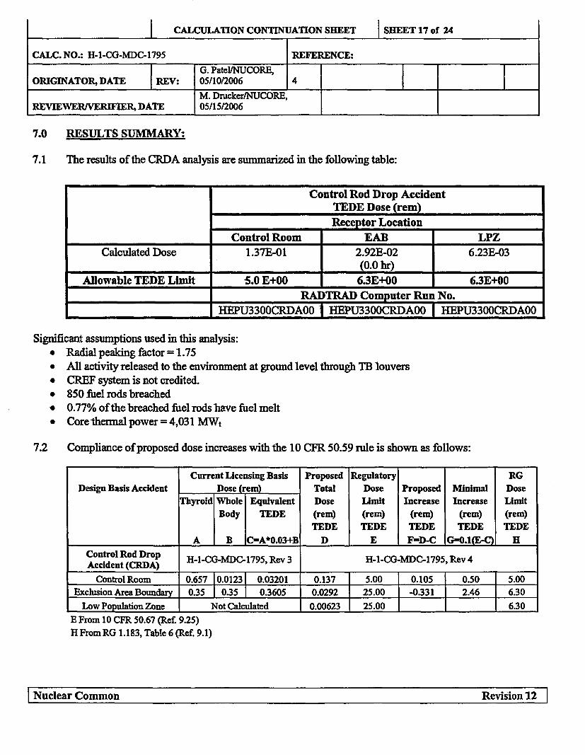
7.0 RESULTS SUMMARY:
7.1 The results of the CRDA analysis are summarized in the following table:
Control Rod Drop AccidentTEDE Dose (rem)Receptor Location
Control Room EAB LPZ
Calculated Dose 1.37E-01 2.92E-02 6.23E-031_ (0.0 hr)
Allowable TEDE Limit 5.0 E+00 6.3E+00 6.3E+00
RADTRAD Computer Run No.
.... _ HEPU3300CRDAOO 1 HEPU3300CRDAOO HEPU3300CRDAOO
Significant assumptions used in this analysis:a Radial peaking factor = 1.75* All activity released to the environment at ground level through TB louvers* CREF system is not credited.* 850 fuel rods breached* 0.77% of the breached fuel rods have fuel melt* Core thermal power = 4,031 MWt
7.2 Compliance of proposed dose increases with the 10 CFR 50.59 rule is shown as follows:
Current Licensing Basis Proposed Regulatory RG
Design Basis Accident Dose (rem) Total Dose Proposed Minimal Dose
Thyroid Whole Equivalent Dose Limit Increase Increase Lmit
Body TEDE (rem) (rem) (rem) (rem) (rem)
TEDE TEDE TEDE TEDE TEDE
A B C--A*0.03+B D E F=D-C Gf0.1(E-Q H
Control Rod Drop H-1-CG-MDC-1795, Rev 3 H-1-CG-MDC-1795, Rev 4Accident (CRDA)
Control Room 0.657 10.01231 0.03201 0.137 5.00 0.105 0.50 5.00
Exclusion Area Boundary 0.35 1 0.35 1 0.3605 0.0292 25.00 -0.331 2.46 6.30
Low Population Zone Not Calculated 0.00623 25.00 6.30
E From 10 CFR 50.67 (Ref. 9.25)
H From RG 1.183, Table 6 (Ref. 9.1)
I Nuclear Common Revision 12 I
I Nuclear Common Revision 12 1

CALCULATION CONTINUATION SHEET SHEET 18 of 24
CALC. NO.: H-1-CG-MDC-1795 REFERENCE:
G. Patel/NUCORE,ORIGINATOR, DATE REV: 05/10/2006 4
M. Drucker/NUCORE,
REVIEWER/VERIFIER, DATE 05/15/2006
8.0 CONCLUSIONS:
The analysis results presented in Section 7.1 indicate that the EAB, LPZ, and CR doses due to a control rod
drop accident are within their allowable TEDE limits. The results indicate that CREF system initiation is not
required during a CRDA.
The comparisons in Section 7.2 document a decrease in the proposed EAB dose; the EAB dose decrease is due
to the lower proposed iodine activity release. The comparisons in Section 7.2 confirm that the proposed
increase in the CR dose is less than the minimal dose increase regulatory limit, and that the total calculated EAB
and CR doses are less than the allowable regulatory guide limits. Therefore, pursuant to 10 CFR 50.59 guidance
as defined in References 9.23 and 9.24, the proposed increase in the core thermal power level and resulting
post-CRDA doses can be adopted as current design andlicensing bases for the HCGS.
9.0 REFERENCES:
1. U.S. NRC Regulatory Guide 1.183, Alternative Radiological Source Terms for Evaluating Design BasisAccidents at Nuclear Power Reactors, July 2000
2. S.L. Humphreys et al., "RADTRAD 3.02: A Simplified Model for Radionuclide Transport and Removal
and Dose Estimation," NUREG/CR-6604, USNRC, April 1998
3. Vendor Technical Document (VTD) No. 430058, Volume 002, Rev 1, EPU TR T0802, RadioactiveSource Term - Core Inventory
4. 10 CFR 50.67, "Accident Source Term."
5. Calculation No. H-1 -ZZ-MDC-1 879, Rev 1, Control Room & Technical Support Center X/Qs Using
ARCON96 Code
6. NUREG-0800, Standard Review Plan 15.4.9 Appendix A, Revision 2, "Radiological Consequences of
Control Rod Drop Accident (BWR)," July 1981
7. Federal Guidance Report 11, EPA-520/1-88-020, Environmental Protection Agency
8. Federal Guidance Report 12, EPA-402-R-93-081, Environmental Protection Agency
9. Calculation No. H-1-ZZ-MDC-1820, Rev 0, Offsite Atmospheric Dispersion Factors
10. Calculation No. H-4-ZZ-MDC-1 882, Rev 0, Control Room Envelope Volume
11. HCGS Procedure No. HC.OP-SO.CG-0001(R), Rev 32, Condenser Air Removal System Operation
12. GE Report NEDO 31400A, October 1992, "Safety Evaluation for Eliminating The Boiling WaterReactor Main Steam Isolation Valve Closure Function and Scram Function of The Main Steam LineRadiation Monitor."
I Nuclear Common Revision 12 1I Nuclear Common
Revision 12 I

CALCULATION CONTINUATION SHEET SHEET 19 of 24
CALC. NO.: H-1-CG-MDC-1795 REFERENCE:
G. Patel/NUCORE,ORIGINATOR, DATE REV: 05/10/2006 4
M. Drucker/NUCORE,REVIEWER/VERIFIER, DATE 05/15/2006
13. HCGS Procedure No. HC.OP-AB.RPV-0008(Q), Rev 0, Reactor Coolant Activity
14. Hope Creek Technical Specification 5.3, Reactor Core - Fuel Assemblies
15. Critical Software Package Identification No. A-O-ZZ-MCS-0225, Rev 2, RADTRAD Computer Code.
16. HCGS General Arrangement Drawings:a. P-0007-0, Rev 7, Plan EL 171'-0" & EL 201'-0"b. P-001 1-0, Rev 5, Sections C-C & D-D
17. HCGS Architectural Drawing No. A-0221-0, Sheet 1, Rev. 10, General Plant Roof Plan
18. HCGS Mechanical P&ID No. M-78-1, Rev 21, Aux Bldg Control Area Air Flow Diagram.
19. HCGS Technical Specification 3/4.3.10, Mechanical Vacuum Pump Trip Instrumentation.
20. Nuclear Fuel Section Design Input File, T03.5-043, Revised Refueling Accident (Bundle Drop)Analysis
21. NRC Safety Evaluation Report NUREG-1048, October 1984, Operation of Hope Creek GeneratingStation
22. U.S. NRC Regulatory Guide 1.49, Rev 1, Power Levels of Nuclear Power Plants
23. PSEG Procedure No. NC.NA-AS.ZZ-0059(Q), Rev 10, 1OCFR50.59 Program Guidance.
24. Nuclear Energy Institute Report No. NEI 96-07, Rev 1, Guidelines for 10 CFR 50.59 Implementation.
25. 10 CFR 50.67, "Accident Source Term."
26. NRC Safety Evaluation Report, Hope Creek Generating Station - Issuance of Amendment No. 134 for
Increase in Allowable MSIV Leakage Rate and Elimination of MSIV Sealing System.
I Nuclear Common Revision 12 1
I Nuclear Common RevIsion 12 I

CALCULATION CONTINUATION SHEET SHEET 20 of 24
CALC. NO.: H-1-CG-MDC-1795 REFERENCE:
G. PatelVNUCORE,ORIGINATOR, DATE REV: 05/10/2006 4
M. Drucker/NUCORE,REVIEWER/VERIFIER, DATE 05/15/2006
10.0 TABLES:
Table 1
CRDA Activity In Peak Failed Fuel
Core Uprated Radial Total Number Post-CRDAIsotope Inventory Core Thermal Peaking Number of Fuel Activity In
Power Level Factor of Fuel Rod Damaged(Ci/MWt) (MWt) Rod Damaged Fuel
In Core (CQ)A B C D E F=(A*B*C*E)/D
1-131 2.779E+04 4031 1.75 47368 850 3.518E+06
1-132 3.991E+04 4031 1.75 47368 850 5.052E+061-133 5.454E+04 4031 1.75 47368 850 6.904E+061-134 5.937E+04 4031 1.75 47368 850 7.515E+061-135 5.117E+04 4031 1.75 47368 850 6.477E+06
KR-83M 2.981E+03 4031 1.75 47368 850 3.774E+05KR- 85 4.711E+02 4031 1.75 47368 850 5.963E+04
KR- 85M 5.908E+03 4031 1.75 47368 850 7A79E+05KR- 87' 1.097E+04 4031 1.75 47368 850 1.389E+06KR-88 1.539E+04 4031 1.75 47368 850 1.948E+06
XE-131M 3.129E+02 4031 1.75 47368 850 3.961E+04XE-133 5.306E+04 4031 1.75 47368 850 6.717E1+06
XE-133M 1.743E+03 4031 1.75 47368 850 2.206E+05XE-135 1.482E+04 4031 1.75 47368 850 1.876E+06
XE-135M 1118E+04 4031 1.75 47368 850 1.415E+06XE-138 4.322E+04 4031 1.75 47368 850 5.471E+06RB-86 1.300E+02 4031 1.75 47368 850 1.646E+04
RB-88 1.574E+04 4031 1.75 47368 850 1.992E+06CS-134 1.319E+04 4031 1.75 47368 850 1.670E+06CS-136 3.704E+03 4031 1.75 47368 850 4.689E+05CS-137* 1.096E+04 4031 1.75 47368 850 1.387E+06
CS-138 4.840E+04 4031 1.75 47368 850 6.127E+06
A From Reference 93* CS-137 inventory includes BA-137M inventory
I Nuclear Common Revision 12' 1I Nuclear Common
RevisIon 12 I
CALCULATION CONTINUATION SHEET SHEET 21 of 24
CALC. NO.: H-1-CG-MDC-1795 REFERENCE:G. Patel/NUCORE,
ORIGINATOR, DATE REV: 05/10/2006 4
M. Dmcker/NUCORE,REVIEWER/VERIFIER, DATE 05/15/2006
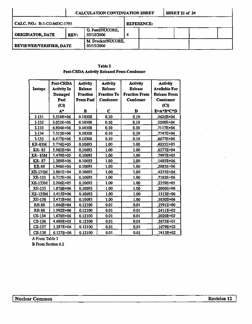
Table 2Post-CRDA Activity Released From Condenser
Post-CRDA Activity Activity Activity Activity
Isotope Activity In Release Release Release Available For
Damaged Fraction Fraction To Fraction From Release From
Fuel From Fuel Condenser Condenser Condenser
(CO (Ci)
A* B C D E=A*B*C*D
1-131 3.518E+06 0.10308 0.10 0.10 .3626E+04
1-132 5.052E+I06 0.10308 0.10 0.10 .5208E+04
1-133 6.904E+06 0.10308 0.10 0.10 .7117E+04
1-134 7.515E+06 0.10308 0.10 0.10 .7747E+04
1-135 6.477E+06 0.10308 0.10 0.10 .6677E+04
KR-83M 3.774E+05 0.10693 1.00 1.00 .4035E+05
KR- 85 5.963E+04 0.10693 1.00 1.00 .6377E+04
KR- 85M I7A79E+05 0.10693 1.00 1.00 .7997E+05
KR- 87 1.389E+06 0.10693 1.00 1.00 .1485E+06
KR-88 1.948E+06 0.10693 1.00 1.00 .2083E+06
XE-131M 3.961E+04 0.10693 1.00 1.00 .4235E+04
XE-133 6.717E+06 0.10693 1.00 1.00 .7182E+06
XE-133M 2.206E+05 0.10693 1.00 1.00 .2359E+05
XE-135 1.876E+06 0.10693 1.00 1.00 2.006E+06
XE-135M 1.415E+06 0.10693 1.00 1.00 .1513E+06
XE-138 5.471E+06 0.10693 1.00 1.00 .5850E+06
RB-86 1.64613+04 0.12100 0.01 0.01 .1991E+00
RB-88 1.992E+06 0.12100 0.01 0.01 .2411E+02
CS-134 1.670E+06 0.12100 0.01 0.01 .2020E+02
CS-136 4.689E+05 0.12100 0.01 0.01 .5673E+01
CS-137 1.38711+06 0.12100 0.01 0.01 .1679E+02
CS-138 6.127E+06 0.12100 0.01 0.01 .7413E+02
A From Table 1B From Section 6.2
I Nuclear Common Revision 12 1I 1~uc1ear Common
Revision 12 I

CALCULATION CONTINUATION SHEET SHEET 22 of 24
CALC. NO.: H-1-CG-MDC-1795 REFERENCE:
G. Patel/NUCORE,ORIGINATOR, DATE REV: 05/10/2006 4
M. Drucker/NUCORE,REVIEWER/VERIFIER, DATE 05/15/2006
11.0 FIGURES:
Figure 1: RADTRAD Nodalization For CRDA Release
[Nuclear Common Revision 12 1I Nuclear Common

CALCULATION CONTINUATION SHEET SHEET 23 of 24
CALC. NO.: H-1-CG-MDC-1795 REFERENCE:
G. Patel/NUCORE,ORIGINATOR, DATE REV: 05/10/2006 4
M. Drucker/NUCORE,REVIEWER/VERIFIER, DATE 05/15/2006
Figure 2 - HCGS Control Room RADTRAD Nodalization
I Nuclear Common Revision 12 1I Nula omnRvso
2I
CALCULATION CONTINUATION SHEET SHEET 24 of 24
CALC. NO.: H-1-CG-MDC-1795 REFERENCE:
G. Patel/NUCORE,ORIGINATOR, DATE REV: 05/10/2006 4
M. Drucker/NUCORE,REVIEWERIVERIFIER, DATE 05/15/2006
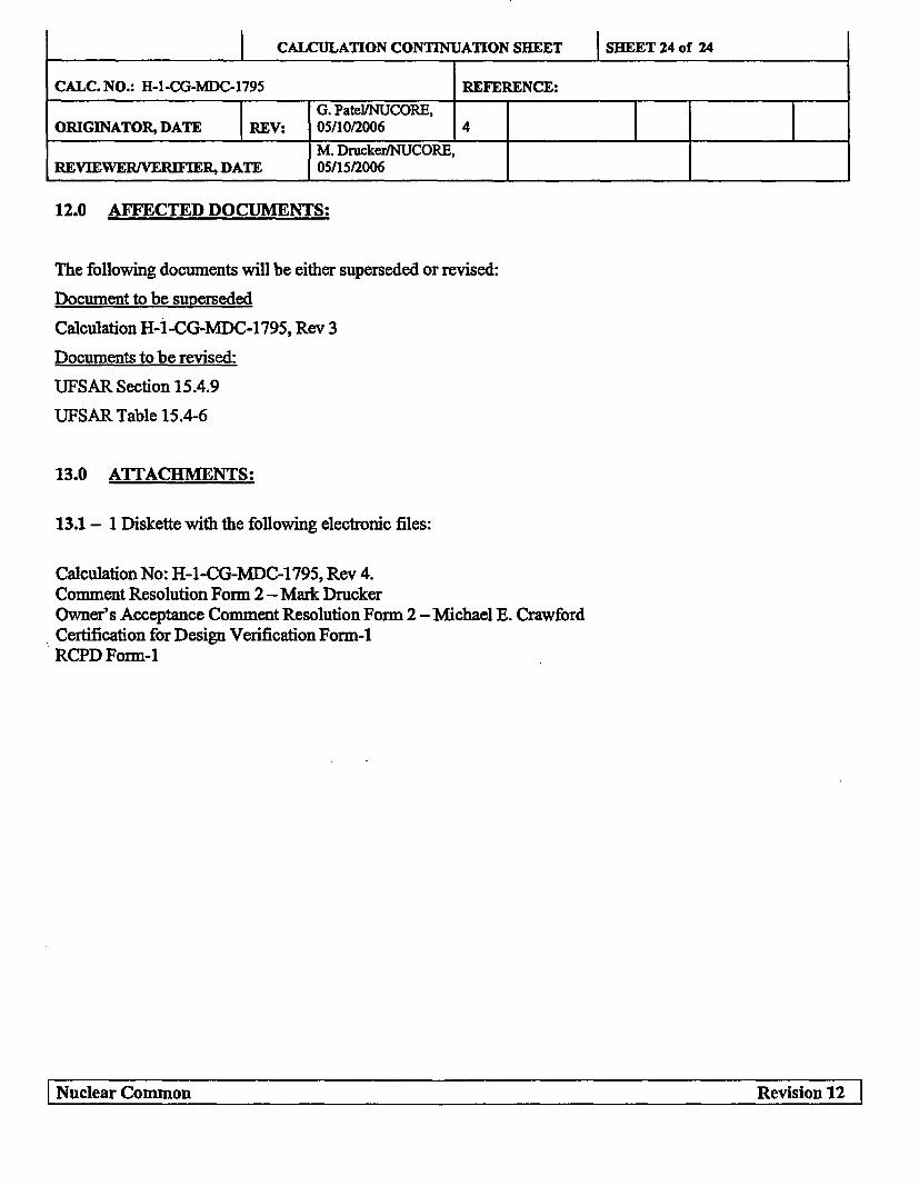
12.0 AFFECTED DOCUMENTS:
The following documents will be either superseded or revised:
Document to be superseded
Calculation H-1 -CG-MDC-1795, Rev 3
Documents to be revised:
UFSAR Section 15.4.9
UFSAR Table 15.4-6
13.0 ATTACHMENTS:
13.1 - 1 Diskette with the following electronic files:
Calculation No: H-1-CG-MDC-1795, Rev 4.Comment Resolution Form 2 - Mark DruckerOwner's Acceptance Comment Resolution Form 2 -Michael E. CrawfordCertification for Design Verification Form-1RCPD Form-1
I Nuclear Common Revision 12 1
I Nuclear Common Revision 12 I