(atlas copco) - industrial power tools 2012
DESCRIPTION
Industrial Power ToolsTRANSCRIPT

www.atlascopco.com
9837
30
00
01
P
rin
ted
in S
wed
en, S
tro
kirk
-Lan
dst
röm
s, 2
010:
1. S
ub
ject
to
alt
erat
ion
wit
ho
ut
pri
or
no
tice
.
Industrial Power Tools 2012Premier productivity solutions
Atlas C
op
co In
du
strial Pow
er Too
ls 201
2
HK catalogue10_cover 5GU.indd 1 2011-11-28 10:53:23

Atlas Copco ToolsNorth American Offices
The Auburn Hills facility is the new home of Atlas CopcoTools and Assembly Systems, USA. Opened in springof 2004, this site is frequently used to host trainingcourses and seminars. Customers are encouraged to visitand test run our products in our state-of-the-art demon-stration room.
A U B U R N H I L L S , M I C H I G A N
2998 Dutton Rd Phone: 800-859-ERGOAuburn Hills, MI 48326 Fax: 248-373-3001
The Canadian office was opened in 1984 and is a salesand service facility. This office has had ISO 9002approval since 1997, a quality system that is appliedto sales, service, and distribution of air powered andelectric hand held power tools.
M I S S I S S A U G A , C A N A D A
Phone: 901-501-9968Mississauga, Ontario L4Z Fax: 901-501-9790
Industrial Tools Division WarrantyAtlas Copco Tools and Assembly Systems warrants to the customer that the products manufactured byAtlas Copco Tools and Assembly Systems and its affiliates shall be free of defects in design, material,and workmanship for the following periods of time:
A. For portable industrial hand tools and hoists, twelve (12) months from date of shipment to customer.
B. All 2000 Series Tools, accessories and parts, three (3) months from date of shipment of customer.
Should any failure to conform with this warranty appear prior to or after shipment of the product tocustomer during the specified periods under normal and proper use and provided the product has beenproperly stored, installed, handled and maintained by the customer, Atlas Copco Tools and AssemblySystems shall, if given prompt notice by customer, repair or replace the nonconforming product or aut-horize repair or replacement by the distributor. Note: This does not include standard wear items such asvanes, o-rings, etc.
Replaced products become the property of Atlas Copco Tools and Assembly Systems.Atlas Copco Tools and Assembly Systems warrants Products or parts there of repaired or replaced
pursuant to the above warranty, under normal or proper use, storage, installation and maintenance,against defects in design, workmanship and material for a period of 30 days from date of start-up of suchrepaired or replaced equipment or parts or the expiration of the original product warranty, whicheveris longer.
Atlas Copco Tools and Assembly Systems´ warranty does not extend to products not manufacturedby Atlas Copco Tool and Assembly Systems or its affiliates. As to such products, customer shall beentitled to proceed only upon the terms of that particular manufacturer’s warranty does not apply todefects in material provided by customer or design stipulated by customer.
Use products, products not manufactured by Atlas Copco Tools and Assembly Systems or its affiliatesand products excluded from the above warranties are sold AS IS with no representation or warranty, andALL WARRANTIES OF QUALITY, WRITTEN, ORAL OR IMPLIED, other than may be expressly agreedto by Atlas Copco Tools and Assembly Systems. In writing, INCLUDING WITHOUT LIMITATON, WAR-RANTIES OR MERCHANTABILITY AND FITNESS ARE HEREBY DISCLAIMED.
THE FOREGOING WARRANTIES ARE EXCLUSIVE AND IN LIEU OF ALL OTHER WARRANTIESOF QUALITY, WRITTEN, ORAL OR IMPLIED AND ALL OTHER WARRANTIES INCLUDING WITHOUTLIMITATION ANY WARRANTY OF MERCHANTABILITY OR FITNESS ARE HERBY DISCLAIMED.Correction of nonconformities as provided above shall be distributor’s exclusive remedy and shall con-stitute fulfillment of all liabilities of Atlas Copco Tools and Assembly Systems (including any liability fordirect, indirect, special incidental or consequential damages) whether in warranty, strict liability, contract,tort, negligence or otherwise with respect to the quality of or any defect in products delivered here under.
OSHA StatementAtlas Copco Tools and Assembly Systems (“the company”) represents to the original user that the pro-ducts advertised herein are designed to comply with The Occupational Safety and Health Act of 1970and as amended as of the date of manufacture. The company shall not be responsible for any failure toso comply with the Act which results from the location, operation, use or maintenance of the products orfrom alteration of the products by persons other than the company or from any option or accessory of theproducts which was available to the original user but omitted at his direction, or from design or instruc-tions furnished by the original user.
The company’s responsibility herein is limited to modification or replacement of the products so thatthe products conform to the regulations applicable at the time of manufacture or at the option of the com-pany to refund to the original user the purchase price less an allowance for normal depreciation upon thereturn of the products to the company. By special request, a sound warranty can be offered; otherwiseall standards under the Act with respect to noise are specifically excluded.
Whether in relation to the above or otherwise, the company will not indemnify the original user for anyfines; penalties neither imposed nor are liable for loss due to delay or any special, indirect or consequen-tial damages of any nature whatsoever.
403 Mattheson Blvd East2H2
Har kört ut på SL-Fogra utan färgkonverte-ring!!!
AT L A S C O P C O T O O L S A N D A S S E M B LY S Y S T E M S C A N A D A
1025 Tristar Drive Phone: 289-562-0100 Mississauga, Ontario Fax: 289-562-6198 L5T 1W5
Atlas omslag insida.indd 1 2012-05-08 09.44

GRINDERS 192Turbine grinders and sanders ......................................... 196Die grinders .................................................................... 198Straight grinders ............................................................. 200Angle grinders ................................................................ 202Angle sanders ................................................................. 204Orbital and random orbital sanders ................................ 206Dust extraction ................................................................ 208Router ............................................................................. 211Nibbler ............................................................................ 211Circular cutters................................................................ 212
PERCUSSIVE TOOLS 213Chipping hammers .......................................................... 216Scalers ............................................................................ 218Rammers ........................................................................ 221Riveting systems............................................................. 222Riveting hammers ........................................................... 223Bucking bars ................................................................... 225Chisels ............................................................................227
DRILLS 231Pistol grip drills................................................................ 234Straight drills ................................................................... 238Angle drills ...................................................................... 240Micro stop drills ............................................................... 244Tappers ........................................................................... 246Screw‑feed drills ............................................................. 248Positive feed drills ........................................................... 249
AUTOMATIC DRILLING AND TAPPING UNITS 253Automatic drilling and tapping units ................................ 254Dimension sketches ....................................................... 258
AIR LINE ACCESSORIES 261Air preparation units .......................................................264Optimizer air tool oil ........................................................268Quick couplings ..............................................................269Claw couplings ...............................................................275Ball valves.......................................................................276Swivel connectors ...........................................................277Fittings ............................................................................278Hoses..............................................................................279Productivity kits ...............................................................285Pre‑mounted hose kits ....................................................286Hose reels.......................................................................287Balancers ........................................................................291Blow guns .......................................................................294Test equipment ...............................................................294
AIR MOTORS 295Vane air motors ...............................................................296LZB vane air motors .......................................................297LZL vane air motors ........................................................297Air motor support ............................................................298
HOISTS AND TROLLEYS 299Air hoists ......................................................................... 301Trolleys ........................................................................... 302
SERVICE 304Service packages ........................................................... 306Service packages for new equipment ............................. 308
DECLARATION OF NOISE & VIBRATION EMISSION 310
TOOL KEY 317
TOOL DESIGNATIONS 323
CONTENTS
PNEUMATIC ASSEMBLY TOOLS 11Pneumatic screwdrivers 14Pistol grip models ............................................................. 16Straight models ................................................................. 20Angle models .................................................................... 22Impact wrenches 25Pistol grip models ............................................................. 27Straight models ................................................................. 28Hydraulic impulse nutrunners – ErgoPulse 30Pistol grip models ............................................................. 32Straight models ................................................................. 35Controlled impulse nutrunners 39Pulsor C ............................................................................ 40Pneumatic nutrunners 42Angle models .................................................................... 43Straight models ................................................................. 58Pistol grip models ............................................................. 63
BATTERY ASSEMBLY TOOLS 70BCP screwdriver, clutch type ............................................ 73BTV nutrunners, clutch type ............................................. 75Tensor STB nutrunners transducerized type .................... 76
ELECTRIC ASSEMBLY TOOLS AND SYSTEMS 82Electric screwdrivers 85EBL ................................................................................... 86MicroTorque ...................................................................... 88Tensor DL ......................................................................... 92Tensor SL ......................................................................... 93Tensor STR ....................................................................... 94Electric nutrunners 98Tensor DS ....................................................................... 100Tensor S.......................................................................... 106Tensor ST ....................................................................... 109Tensor STR ..................................................................... 117Controller and software 125DS/DL Drive .................................................................... 127Power Focus .................................................................. 128Software ToolsTalk .......................................................... 130Quality Integrated Fastening 131Station hardware ........................................................... 133Station software .............................................................. 135
TOOL ACCESSORIES 137TPS Controller ................................................................ 138Torque arms .................................................................... 140Bits and power sockets ................................................... 150
FIXTURED APPLICATIONS 157Fixtured nutrunners QST ................................................ 160Fixtured nutrunners ETX ................................................ 164Controllers and software ................................................. 166Power MACS .................................................................. 167MSB, DB ......................................................................... 168Power Focus ................................................................... 171Software ToolsTalk .......................................................... 172
QUALITY ASSURANCE IN TIGHTENING 173STanalyser ...................................................................... 175QRTT Transducers ......................................................... 178IRTT‑B Transducers ........................................................ 178SRTT‑B Transducers ...................................................... 179MRTT‑C Transducers ..................................................... 180ACTA MT Transducer ..................................................... 181STwrench ........................................................................ 183BLM TPT, μ-Tester .......................................................... 189BLM Joint Simulator Bench AD ...................................... 190ToolsTalk QAT ................................................................. 191
Contents.indd 1 2012-02-09 07:44:48

2
Whatever your business, we can add value
A global technology leader, Atlas Copco is a true solutions pro-vider to the manufacturing industries of the world. You will find the high-tech tools, assembly systems and process software of the future in our range today. From big bolt fastening technology for offroad vehicles, down to “micro” tools for tiny fasteners in the electronics industry, Atlas Copco has the solutions you need to stay ahead of the game.
You talk, we listenFor us, listening is crucial. Whether you build vehicles, aircraft, appliances or electronics, your ongoing feedback gives us valuable insights into your business and the challenges you face to remain competitive. Our response? A continuous stream of innovations that raise productivity in your operation.
We lead, others followAtlas Copco leads the world for high-tech operator-friendly tools supported by advanced process control and qual-ity assurance software. We currently have more than 4,000 tools in our range and our dynamic product de-velopment program generates a large number of innovative new products every year.
Am_Intropages.indd 2 2012-02-06 09:16:20

3
Lean productionIn the automotive and other industries our high-performance, hand-operated and fixtured assembly tools and exten-sive know-how make a major contribu-tion to lean production. Every third car in the Western world was built using our cuttingedge fastening solutions.
Safety critical applicationsOn assembly lines in the manufactur-ing industries many joints are safety critical. Atlas Copco controlled fasten-ing tools, fixtured solutions and market-leading assembly process software enable our customers to meet today’s demands for joint validation, documen-tation and traceability.
Productivity starts with peopleAtlas Copco continues to lead the field for ergonomically designed tools that minimize operator fatigue and increase individual productivity. Outstanding examples are our vibration-damped riv-eting systems, chosen by major aircraft manufacturers, and our turbo-powered grinders that have made heavy tasks lighter for tool operators in heavy metal fabrication operations.
Committed to sustainable productivityOur brand promise embraces virtually all aspects of our operations. It means that Atlas Copco people do everything they can to ensure reliable, lasting re-sults with responsible use of resources – human, natural and capital.
In our own operations worldwide we focus on maintaining a high com-petence level, and health and safety in the workplace. We constantly strive to reduce the impact of production on the environment.
A true innovator, Atlas Copco contin-uously develops new, energy efficient products with lowest cost of ownership. Safeguarding health and boosting productivity at our customers’ plants through better ergonomics have long been part of our business philosophy.
All-in-all, we are acting for a better society around us.
Am_Intropages.indd 3 2012-02-06 09:16:23

4
Close to your business, in touch with your needs
With resources in more than 90 countries, we can offer you a profitable partnership on a local or global basis. Atlas Copco product specialists, distributors and service engineers are on hand worldwide to share the responsibility for keeping your production on-line around the clock. We understand the challenges you face and our commitment to your productivity is total.
Am_Intropages.indd 4 2012-02-06 09:16:29

5
Customer CentersUnique among competitors,Atlas Copco has Customer Centers throug h out the world. Their common goal is to give you the best return on your investment. Once the tools are installed, our entire organization is dedicated to keeping your operation on-line.
Application centersOur strategically located Application Centers configure complete assembly stations with process monitoring and control for the automotive, aero space and other industries where joint quality is crucial. Using standard components we can deliver a complete tightening station for quality integrated fasten ing in just three weeks.
Whatever your language We offer customer training and a wide range of training materials, including e-learning, interactive presentations and pocket guides in several languages. Operator and service instructions, sup-plied with all products, are available in 21 languages.
Order-driven productionAt our tool plant, production is order driven and lead times are extremely short. Before leaving our factory every tool and system is rigorously tested. Quality control and test data are stored for each product.
Fast deliveryPlace orders by phone or on-line. Or-ders received before 16:00 are packed and shipped the same day. European customers receive deliveries from our standard range within 24 to 48 hours from our worldwide distribution ware-house in Belgium. Deliveries to other continents take up to 72 hours.
Am_Intropages.indd 5 2012-02-06 09:16:33

6
Quality, every step of the way
Atlas Copco is a truly innovative company, continuously striving for excellence. Our dynamic product development program gen-erates a large number of new products every year. We currently have more than 4,000 tools in our range and we own more than 400 patents. Covering all our operations, we have a quality target: To attain maximum quality at all stages from initial development to spare part deliveries.
Proof of company excellenceThe ISO 9001 Certificate confirms that Atlas Copco Tools product company con-forms to the Quality Standard ISO 9001. Our quality policy is:• To fulfill customers’ expectations.• To deliver problem-free products at
the right time.• To continuously improve our
products, services and processes. • To have motivated personnel with
clearly defined goals.In effect it means you know what you are getting. Carefully specified manu-facturing processes guarantee that every product leaving our factory meets exactly the same standards of quality and performance.
EC declaration of conformityFrom January 1, 1995, all machines produced by Atlas Copco conform with the EC Machine Directive which focuses on safety. From December 29, 2009 the directive is 2006/42/EC.
Each Atlas Copco tool bears the CE marking and is accompanied by detailed safety and operating instructions and a declaration of conformity.
Am_Intropages.indd 6 2012-02-06 09:16:37
7
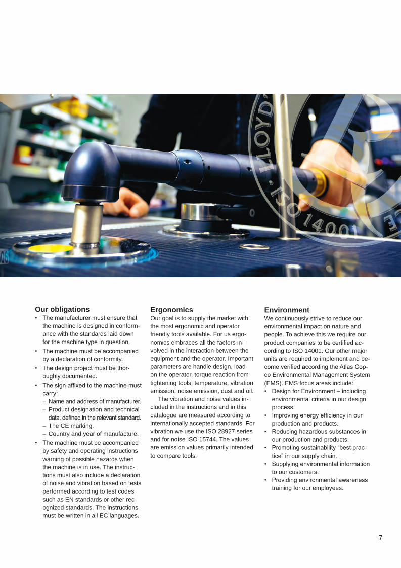
Our obligations• The manufacturer must ensure that
the machine is designed in conform-ance with the standards laid down for the machine type in question.
• The machine must be accompanied by a declaration of conformity.
• The design project must be thor-oughly documented.
• The sign affixed to the machine must carry:
– Name and address of manufacturer. – Product designation and technical
data, defined in the relevant standard. – The CE marking. – Country and year of manufacture.• The machine must be accompanied
by safety and operating instructions warning of possible hazards when the machine is in use. The instruc-tions must also include a declaration of noise and vibration based on tests performed according to test codes such as EN standards or other rec-ognized standards. The instructions must be written in all EC languages.
ErgonomicsOur goal is to supply the market with the most ergonomic and operator friendly tools available. For us ergo-nomics embraces all the factors in-volved in the interaction between the equipment and the operator. Important parameters are handle design, load on the operator, torque reaction from tightening tools, temperature, vibration emission, noise emission, dust and oil.
The vibration and noise values in-cluded in the instructions and in this catalogue are measured according to internationally accepted standards. For vibration we use the ISO 28927 series and for noise ISO 15744. The values are emission values primarily intended to compare tools.
EnvironmentWe continuously strive to reduce our environmental impact on nature and people. To achieve this we require our product companies to be certified ac-cording to ISO 14001. Our other major units are required to implement and be-come verified according the Atlas Cop-co Environmental Management System (EMS). EMS focus areas include:• Design for Environment – including
environmental criteria in our design process.
• Improving energy efficiency in our production and products.
• Reducing hazardous substances in our production and products.
• Promoting sustainability “best prac-tice” in our supply chain.
• Supplying environmental information to our customers.
• Providing environmental awareness training for our employees.
Am_Intropages.indd 7 2012-02-06 09:16:41
8
Five steps to zero-fault fastening
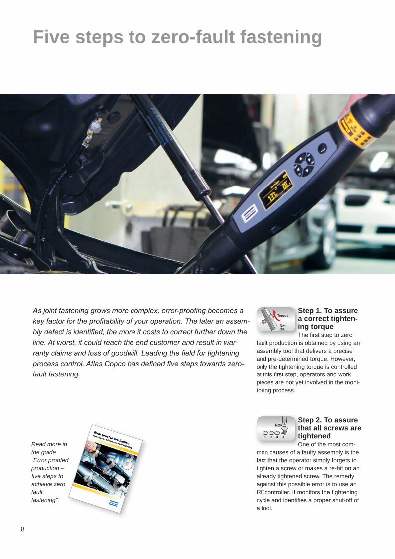
As joint fastening grows more complex, error-proofi ng be comes a key factor for the profi tability of your operation. The later an assem-bly defect is identifi ed, the more it costs to correct further down the line. At worst, it could reach the end customer and result in war-ranty claims and loss of goodwill. Leading the fi eld for tightening process control, Atlas Copco has defi ned fi ve steps towards zero-fault fastening.
Step 1. To assure a correct tighten-ing torqueThe fi rst step to zero
fault production is obtained by using an assembly tool that delivers a precise and pre-determined torque. However, only the tightening torque is controlled at this fi rst step, operators and work pieces are not yet involved in the moni-toring process.
Step 2. To assure that all screws are tightenedOne of the most com-
mon causes of a faulty assembly is the fact that the operator simply forgets to tighten a screw or makes a re-hit on an already tightened screw. The remedy against this possible error is to use an REcontroller. It monitors the tightening cycle and identifi es a proper shut-off of a tool.
Read more inthe guide“Error proofedproduction –fi ve steps toachieve zerofaultfastening”.
Am_Intropages.indd 8 2012-02-06 09:16:49

9
Step 3. To assure that the joint is correctWith step 1 and 2
the tool and the operator have been taken into consideration. However, the joint itself can also be a cause of the incorrect tightening. There can be several reasons for this. Missing parts like seals or washers will change the characteristics of the joint. Damaged threads or debris in the joint also lead to an improperly tightened joint.
The way to detect these types of faulty joints is to monitor the tight ening angle during the tightening process.
Operator guidance and feedback is provided by signal lights on the tool and by using socket selectors etc.
Step 4. To assure that safety critical joints are tight-ened properly
This is the level required for safety criti-cal joints. All tightening data is docu-mented and can be retrieved for error analyses. Documented tight ening data for safety critical fasten ers are essen-tial in order to avoid or limit recalls and warranty claims.
Step 5. To assure zero fault produc-tionHaving reached step 4
in the advance to zero fault production still leaves room for mistakes. With step 5 two further elements are introduced for fault-free production. One element is the introduction of part identifi cation, the other is reject management. With step fi ve the tool controllers are not only networked – they are also con-nected to the factory network. Informa-tion about the components is sent over the factory network. By identifying the components that are to be assembled, relevant information is transferred to the tool controller via the network. This safeguards both that the correct com-ponent is being assembled and that corresponding tightening parameters are chosen.
Am_Intropages.indd 9 2012-02-06 09:16:53
10
grinding wheels, etc. When measuring noise, Atlas Copco
uses the standard ISO 15744. The figure given in this catalogue is the measured sound pressure level. If the measured value exceeds 80 dB(A), the sound power level is also given. The standards describe how to calculate this figure. The uncertainty in the fig-ures from variations in the test method and production is 3 dB(A). In-use noise values close to the operator’s ear may differ considerably from the given values particularly since in many ap-plications the sound from the process is higher than the unloaded tool noise.
We, Atlas Copco Tools AB, cannot be held liable for the consequences of using the declared values, instead of values reflecting the actual exposure, in an individual risk assessment in a workplace situation over which we have no control. We recommend a program of health surveillance to detect early symptoms which may relate to noise or vibration exposure, so that manage-ment procedures can be modified to help prevent future impairment.
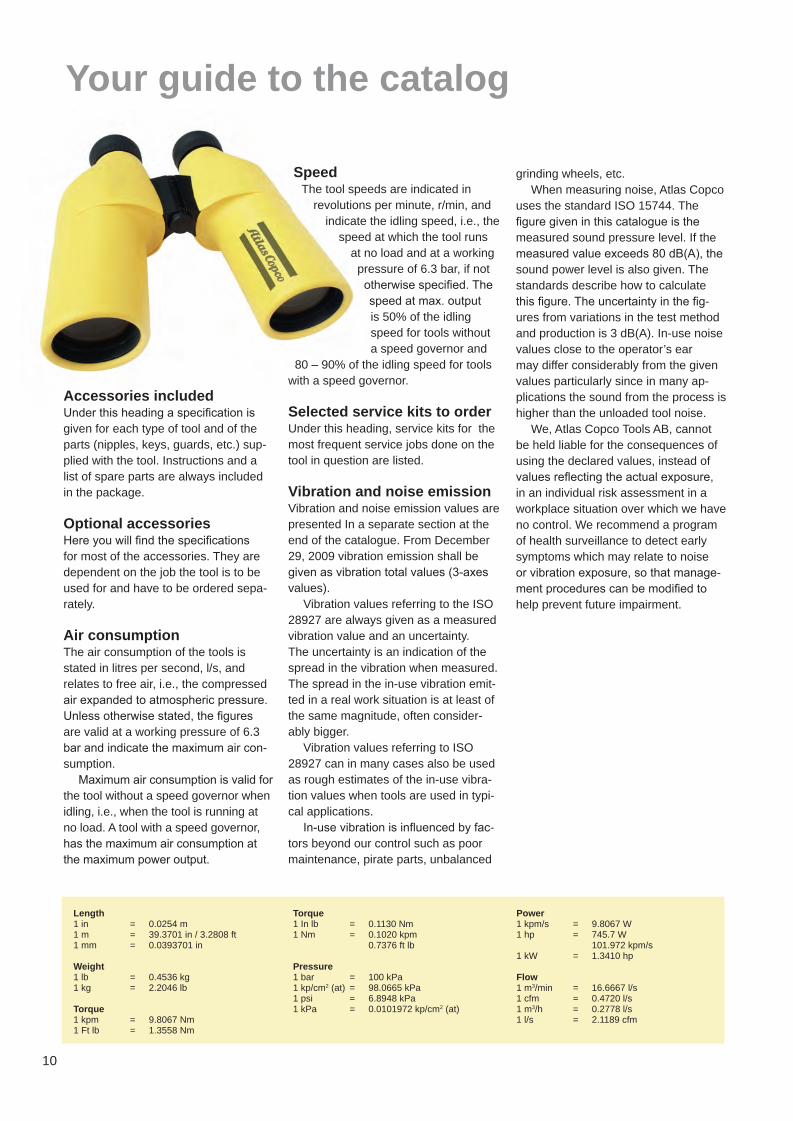
Your guide to the catalog
Accessories includedUnder this heading a specification is given for each type of tool and of the parts (nipples, keys, guards, etc.) sup-plied with the tool. Instructions and a list of spare parts are always included in the package.
Optional accessoriesHere you will find the specifications for most of the accessories. They are dependent on the job the tool is to be used for and have to be ordered sepa-rately.
Air consumptionThe air consumption of the tools is stated in litres per second, l/s, and relates to free air, i.e., the compressed air expanded to atmospheric pressure. Unless otherwise stated, the figures are valid at a working pressure of 6.3 bar and indicate the maximum air con-sumption.
Maximum air consumption is valid for the tool without a speed governor when idling, i.e., when the tool is running at no load. A tool with a speed governor, has the maximum air consumption at the maximum power output.
SpeedThe tool speeds are indicated in
revolutions per minute, r/min, and indicate the idling speed, i.e., the
speed at which the tool runs at no load and at a working pressure of 6.3 bar, if not otherwise specified. The speed at max. output is 50% of the idling speed for tools without a speed governor and
80 – 90% of the idling speed for tools with a speed governor.
Selected service kits to orderUnder this heading, service kits for the most frequent service jobs done on the tool in question are listed.
Vibration and noise emissionVibration and noise emission values are presented In a separate section at the end of the catalogue. From December 29, 2009 vibration emission shall be given as vibration total values (3-axes values).
Vibration values referring to the ISO 28927 are always given as a measured vibration value and an uncertainty. The uncertainty is an indication of the spread in the vibration when measured. The spread in the in-use vibration emit-ted in a real work situation is at least of the same magnitude, often consider-ably bigger.
Vibration values referring to ISO 28927 can in many cases also be used as rough estimates of the in-use vibra-tion values when tools are used in typi-cal applications.
In-use vibration is influenced by fac-tors beyond our control such as poor maintenance, pirate parts, unbalanced
Length1 in = 0.0254 m1 m = 39.3701 in / 3.2808 ft1 mm = 0.0393701 in
Weight1 lb = 0.4536 kg1 kg = 2.2046 lb
Torque1 kpm = 9.8067 Nm1 Ft lb = 1.3558 Nm
Torque1 In lb = 0.1130 Nm1 Nm = 0.1020 kpm 0.7376 ft lb
Pressure1 bar = 100 kPa1 kp/cm2 (at) = 98.0665 kPa1 psi = 6.8948 kPa1 kPa = 0.0101972 kp/cm2 (at)
Power1 kpm/s = 9.8067 W1 hp = 745.7 W 101.972 kpm/s1 kW = 1.3410 hp
Flow1 m3/min = 16.6667 l/s1 cfm = 0.4720 l/s1 m3/h = 0.2778 l/s1 l/s = 2.1189 cfm
Am_Intropages.indd 10 2012-02-06 09:17:02

PneumaticAssembly Tools
Contents PageIntroduction ......................................... 12Screwdrivers 14Pistol grip models ................................ 16Straight models.................................... 20Angle models ....................................... 22Impact wrenches 25Pistol grip models ................................ 27Straight models.................................... 28Hydraulic impulse nutrunners 30 ErgoPulse Pistol grip models ................................ 32Straight models.................................... 35Controlled impulse nutrunners 39Pulsor C ............................................... 40Nutrunners 42Angle models ....................................... 43Straight models.................................... 58Pistol grip models ................................ 63
Am_pneuintro.indd 11 2012-02-09 10:26:43
12 Pneumatic Assembly Tools
Pneu
mat
ic A
ssem
bly
Tool
s
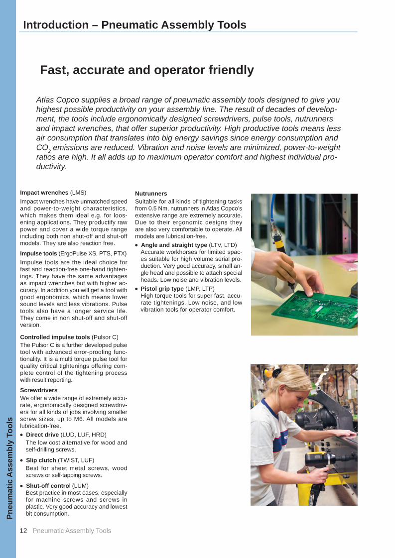
Impact wrenches (LMS)Impact wrenches have unmatched speed and power-to-weight characteristics, which makes them ideal e.g. for loos-ening applications. They productify raw power and cover a wide torque range including both non shut-off and shut-off models. They are also reaction free.
Impulse tools (ErgoPulse XS, PTS, PTX)Impulse tools are the ideal choice for fast and reaction-free one-hand tighten-ings. They have the same advantages as impact wrenches but with higher ac-curacy. In addition you will get a tool with good ergonomics, which means lower sound levels and less vibrations. Pulse tools also have a longer service life. They come in non shut-off and shut-off version.
Controlled impulse tools (Pulsor C)The Pulsor C is a further developed pulse tool with advanced error-proofing func-tionality. It is a multi torque pulse tool for quality critical tightenings offering com-plete control of the tightening process with result reporting.
ScrewdriversWe offer a wide range of extremely accu-rate, ergonomically designed screwdriv-ers for all kinds of jobs involving smaller screw sizes, up to M6. All models are lubrication-free.l Direct drive (LUD, LUF, HRD) The low cost alternative for wood and
self-drilling screws.
l Slip clutch (TWIST, LUF) Best for sheet metal screws, wood
screws or self-tapping screws.
l Shut‑off control (LUM) Best practice in most cases, especially
for machine screws and screws in plastic. Very good accuracy and lowest bit consumption.
NutrunnersSuitable for all kinds of tightening tasks from 0.5 Nm, nutrunners in Atlas Copco’s extensive range are extremely accurate. Due to their ergonomic designs they are also very comfortable to operate. All models are lubrication-free.l Angle and straight type (LTV, LTD) Accurate workhorses for limited spac-
es suitable for high volume serial pro-duction. Very good accuracy, small an-gle head and possible to attach special heads. Low noise and vibration levels.
l Pistol grip type (LMP, LTP) High torque tools for super fast, accu-
rate tightenings. Low noise, and low vibration tools for operator comfort.
Introduction – Pneumatic Assembly Tools
Fast, accurate and operator friendly
Atlas Copco supplies a broad range of pneumatic assembly tools designed to give you highest possible productivity on your assembly line. The result of decades of develop-ment, the tools include ergonomically designed screwdrivers, pulse tools, nutrunners and impact wrenches, that offer superior productivity. High productive tools means less air consumption that translates into big energy savings since energy consumption and CO2 emissions are reduced. Vibration and noise levels are minimized, power-to-weight ratios are high. It all adds up to maximum operator comfort and highest individual pro-ductivity.
Am_pneuintro.indd 12 2012-02-10 10:35:39
Pneu
mat
ic A
ssem
bly
Tool
s
Pneumatic Assembly Tools 13
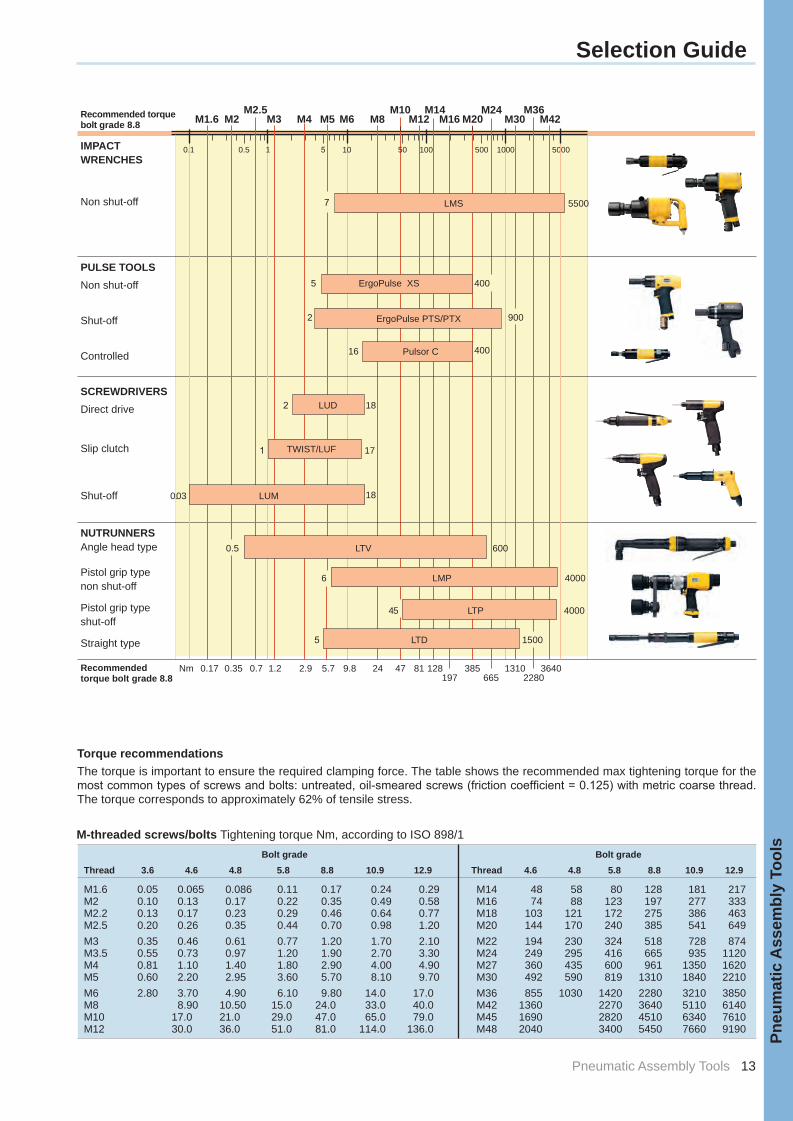
500 1000 500010050.50.1
M1.6 M2M2.5
M3 M4 M5 M6 M8M10 M14
M12 M16 M20M24
M30M36
M42
1 17TWIST/LUF
0.03 18LUM
0.17Nm 0.35 0.7 1.2 2.9 5.7 9.8 24 47 81 128197
385665
13102280
3640
1 10
5 ErgoPulse XS 400
2 LUD 18
LTV 6000.5
LMP6 4000
5 LTD 1500
5500LMS7
LTP45 4000
Pulsor C 40016
2 ErgoPulse PTS/PTX 900
50
Bolt grade Bolt gradeThread 3.6 4.6 4.8 5.8 8.8 10.9 12.9 Thread 4.6 4.8 5.8 8.8 10.9 12.9
M1.6 0.05 0.065 0.086 0.11 0.17 0.24 0.29 M14 48 58 80 128 181 217M2 0.10 0.13 0.17 0.22 0.35 0.49 0.58 M16 74 88 123 197 277 333M2.2 0.13 0.17 0.23 0.29 0.46 0.64 0.77 M18 103 121 172 275 386 463M2.5 0.20 0.26 0.35 0.44 0.70 0.98 1.20 M20 144 170 240 385 541 649M3 0.35 0.46 0.61 0.77 1.20 1.70 2.10 M22 194 230 324 518 728 874M3.5 0.55 0.73 0.97 1.20 1.90 2.70 3.30 M24 249 295 416 665 935 1120M4 0.81 1.10 1.40 1.80 2.90 4.00 4.90 M27 360 435 600 961 1350 1620M5 0.60 2.20 2.95 3.60 5.70 8.10 9.70 M30 492 590 819 1310 1840 2210M6 2.80 3.70 4.90 6.10 9.80 14.0 17.0 M36 855 1030 1420 2280 3210 3850M8 8.90 10.50 15.0 24.0 33.0 40.0 M42 1360 2270 3640 5110 6140M10 17.0 21.0 29.0 47.0 65.0 79.0 M45 1690 2820 4510 6340 7610M12 30.0 36.0 51.0 81.0 114.0 136.0 M48 2040 3400 5450 7660 9190
IMPACTWRENCHES
Non shut-off
PULSE TOOLSNon shut-off
Shut-off
Controlled
SCREWDRIVERSDirect drive
Slip clutch
Shut-off
NUTRUNNERSAngle head type
Pistol grip typenon shut-off
Pistol grip typeshut-off
Straight type
Recommendedtorque bolt grade 8.8
Recommended torque bolt grade 8.8
Selection Guide
Torque recommendationsThe torque is important to ensure the required clamping force. The table shows the recommended max tightening torque for the most common types of screws and bolts: untreated, oil-smeared screws (friction coeffi cient = 0.125) with metric coarse thread. The torque corresponds to approximately 62% of tensile stress.
M‑threaded screws/bolts Tightening torque Nm, according to ISO 898/1
Am_pneuintro.indd 13 2012-02-09 10:27:06
14
Pneu
mat
ic S
crew
driv
ers
14 Pneumatic Assembly Tools
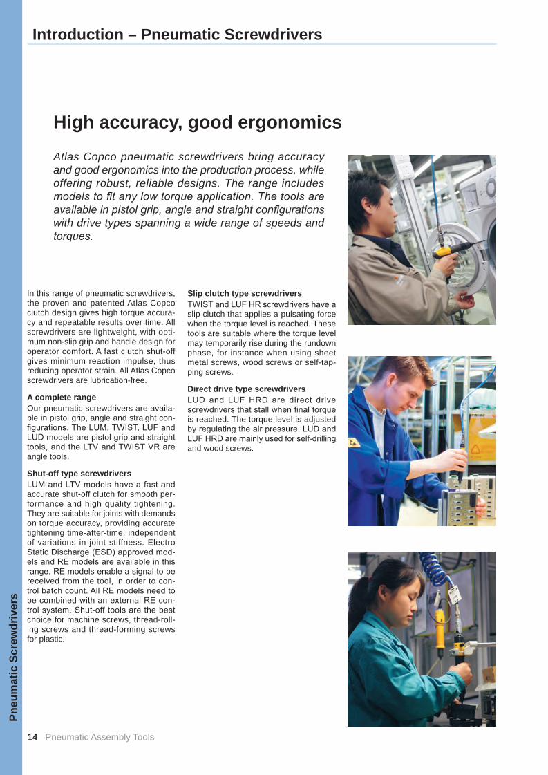
Introduction – Pneumatic Screwdrivers
High accuracy, good ergonomics
In this range of pneumatic screwdrivers, the proven and patented Atlas Copco clutch design gives high torque accura-cy and repeatable results over time. All screwdrivers are lightweight, with opti-mum non-slip grip and handle design for operator comfort. A fast clutch shut-off gives minimum reaction impulse, thus reducing operator strain. All Atlas Copco screwdrivers are lubrication-free.
A complete rangeOur pneumatic screwdrivers are availa-ble in pistol grip, angle and straight con-figurations. The LUM, TWIST, LUF and LUD models are pistol grip and straight tools, and the LTV and TWIST VR are angle tools.
Shut-off type screwdriversLUM and LTV models have a fast and accurate shut-off clutch for smooth per-formance and high quality tightening. They are suitable for joints with demands on torque accuracy, providing accurate tightening time-after-time, independent of variations in joint stiffness. Electro Static Discharge (ESD) approved mod-els and RE models are available in this range. RE models enable a signal to be received from the tool, in order to con-trol batch count. All RE models need to be combined with an external RE con-trol system. Shut-off tools are the best choice for machine screws, thread-roll-ing screws and thread-forming screws for plastic.
Slip clutch type screwdriversTWIST and LUF HR screwdrivers have a slip clutch that applies a pulsating force when the torque level is reached. These tools are suitable where the torque level may temporarily rise during the rundown phase, for instance when using sheet metal screws, wood screws or self-tap-ping screws.
Direct drive type screwdriversLUD and LUF HRD are direct drive screwdrivers that stall when final torque is reached. The torque level is adjusted by regulating the air pressure. LUD and LUF HRD are mainly used for self-drilling and wood screws.
Atlas Copco pneumatic screwdrivers bring accuracy and good ergonomics into the production process, while offering robust, reliable designs. The range includes models to fit any low torque application. The tools are available in pistol grip, angle and straight configurations with drive types spanning a wide range of speeds and torques.
Am_Pneuscrewdrivers.indd 14 2012-02-06 09:29:19
15
Pneu
mat
ic S
crew
driv
ers
Pneumatic Assembly Tools 15
LUM12
LTV18
LTV009
LUM12
LTV009
LUM12
LTV18
LTV009
LUM02LUM10
LUM12
LTV18LTV009
LUM22
LUM02LUM10
LUM22
LUM02LUM10
LUM22
LUM10
LUM02
LUM22
LUF34
TWIST12/22
LUD
LUF34
LUF34
TWIST12
LUD12/22TWIST12/22
LUM32
LUM32
LUM32
LUM32
LTV18
M1.6 M2 M2.5 M3.5 M4 M6 M3 M5
M1.6 M2 M2.5 M3.5 M4 M6 M3 M4.5 M5
M2 M4 M6 M5 M3
ST2.2 ST2.9 ST4.2ST3.5 ST4.8 ST5.5 ST6.3
ST2.2 ST2.9 ST4.2ST3.5 ST4.8 ST5.5 ST6.3
ST2.2 ST2.9 ST4.2ST3.5 ST4.8 ST5.5 ST6.3
0.09 0.2 0.4 0.6 1.0 1.4 2.9 4.9
0.2 0.4 0.7 1.2 1.9 2.9 4.3 5.7 9.8
1.40.5 11.03.2 6.5
0.3 1.8 2.9 4.2 6.7 9.11.0
0.3 1.8 2.9 4.2 6.7 9.11.0
1.5 3 7.5 125
0.3 1.8 2.9 4.2 6.7 9.11.0
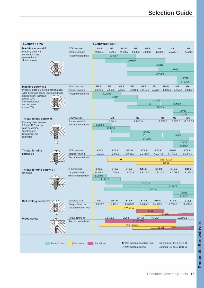
Selection Guide
SCREW TYPE
SCREWDRIVER
Ø Screw size
Recommended tool
Machine screw 4.8Property class 4.8 normal for crossrecessed andslotted screws
Machine screw 8.8Property class 8.8 normal for hexagon,Allen head and Torx®. Locking nut withplastic insert, increasetorque 10%,mechanical-locknut, increasetorque 20%
Thread rolling screw-MProperty class between8.8 and 10.9 due tocase hardening.Taptite® andSwageform areexamples
Thread forming screw-ST
Thread forming screw-STfor plastic
Self drilling screw-ST
Wood screw
With optional coupling-ring.
With optional spring. Ordering No. 4210 1831 00
Shut-off clutch Slip clutch Direct drive
Torque Nm/in lb
Ø Screw size
Recommended tool
Torque Nm/in lb
Ø Screw size
Recommended toolTorque Nm/in lb
Ø Screw size
Recommended tool
Torque Nm/in lb
Ø Screw size
Recommended toolTorque Nm/in lb
Ø Screw size
Recommended toolTorque Nm/in lb
Torque Nm/in lb
Recommended tool
/0.8 /1.8 /3.5 /5.3 /8.8 /12.4 /25.7 /43.4
/1.8 /3.5 /6.2 /10.6 /16.8 /25.7 /38.1 /50.4 /86.7
/12.4 /4.4 /97.3/28.3 /57.5
/2.7 /15.9 /25.7 /37.2 /59.3 /80.5 /8.8
/2.7 /15.9 /25.7 /37.2 /59.3 /80.5 /8.8
/13.3 /26.5 /66.4 /106.2 /44.2
/2.7 /15.9 /25.7 /37.2 /59.3 /80.5 /8.8
Ordering No. 4210 2316 01
SCREW TYPE SCREWDRIVER
Am_Pneuscrewdrivers.indd 15 2012-02-06 09:29:22
16
Pneu
mat
ic S
crew
driv
ers
16 Pneumatic Assembly Tools
Air consumption Rec. Air Torque range Free at hose inlet soft joint speed Weight Length CS distance free speed size thread Model Nm in lb r/min kg lb mm mm l/s cfm mm in Ordering No.With trigger startLUM22 HR3 0.6-3 5.3-26.5 2200 0.85 1.9 186 18 7.5 16 8 1/4 8431 0269 00LUM22 HR3-RE 0.6-3 5.3-26.5 2200 0.85 1.9 186 18 7.5 16 8 1/4 8431 0278 63LUM22 HR4 0.6-4 5.3-35.4 1650 0.85 1.9 186 18 7.5 16 8 1/4 8431 0269 02LUM22 HR4-RE 0.6-4 5.3-35.4 1650 0.85 1.9 186 18 7.5 16 8 1/4 8431 0278 65LUM22 HR6 1.5-6.5 13.3-57.5 1150 0.85 1.9 186 18 7.5 16 8 1/4 8431 0269 01LUM22 HR6-RE 1.5-6.5 13.3-57.5 1150 0.85 1.9 186 18 7.5 16 8 1/4 8431 0278 64LUM22 HR10 3.5-10 31-88.5 750 1 2.2 218 18 7.5 16 10 1/4 8431 0269 03LUM22 HR10-RE 3.5-10 31-88.5 750 1 2.2 218 18 7.5 16 10 1/4 8431 0278 66LUM22 HR12 3.5-12.5 31-110.6 500 1 2.2 210 18 7.5 16 10 1/4 8431 0269 04LUM22 HR12-RE 3.5-12.5 31-110.6 500 1 2.2 210 18 7.5 16 10 1/4 8431 0278 67LUM22 HR12-370 3.5-12.5 31-110.6 370 1 2.2 210 18 7.5 16 10 1/4 8431 0269 05LUM32 HR10 5-10 44.2-88.5 750 0.72 1.6 183 18.5 7.5 16 10 1/4 8431 0269 90LUM32 HR15 7.5-15.5 66-137.2 450 0.72 1.6 183 18.5 7.5 16 10 1/4 8431 0269 91With trigger and push start LUM22 HR3-P 0.6-3 5.3-26.5 2200 0.85 1.9 186 21 7.5 16 8 1/4 8431 0269 06LUM22 HR4-P 0.6-4 5.3-35.4 1650 0.85 1.9 186 21 7.5 16 8 1/4 8431 0269 08LUM22 HR6-P 1.5-6.5 13.3-57.5 1150 0.85 1.9 186 21 7.5 16 8 1/4 8431 0269 07LUM22 HR10-P 3.5-10 31-88.5 750 1 2.2 218 21 7.5 16 10 1/4 8431 0269 09LUM22 HR12-P 3.5-12.5 31-110.6 500 1 2.2 210 21 7.5 16 10 1/4 8431 0269 10LUM22 HR12-370-P 3.5-12.5 31-110.6 370 1 2.2 210 21 7.5 16 10 1/4 8431 0269 11
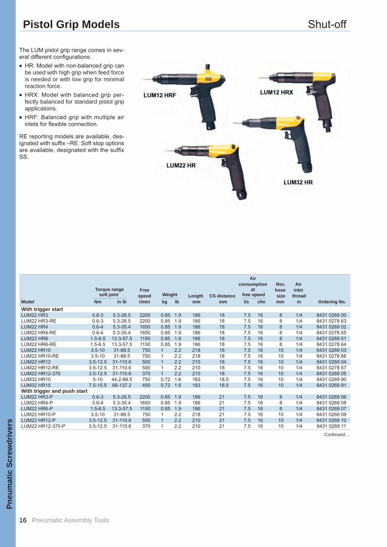
Pistol Grip Models Shut-off
Continued....
The LUM pistol grip range comes in sev-eral different confi gurations:l HR: Model with non-balanced grip can
be used with high grip when feed force is needed or with low grip for minimal reaction force.
l HRX: Model with balanced grip per-fectly balanced for standard pistol grip applications.
l HRF: Balanced grip with multiple air inlets for fl exible connection.
RE reporting models are available, des-ignated with suffi x –RE. Soft stop options are available, designated with the suffi x SS.
Am_Pneuscrewdrivers.indd 16 2012-02-06 09:29:23
17
Pneu
mat
ic S
crew
driv
ers
Pneumatic Assembly Tools 17
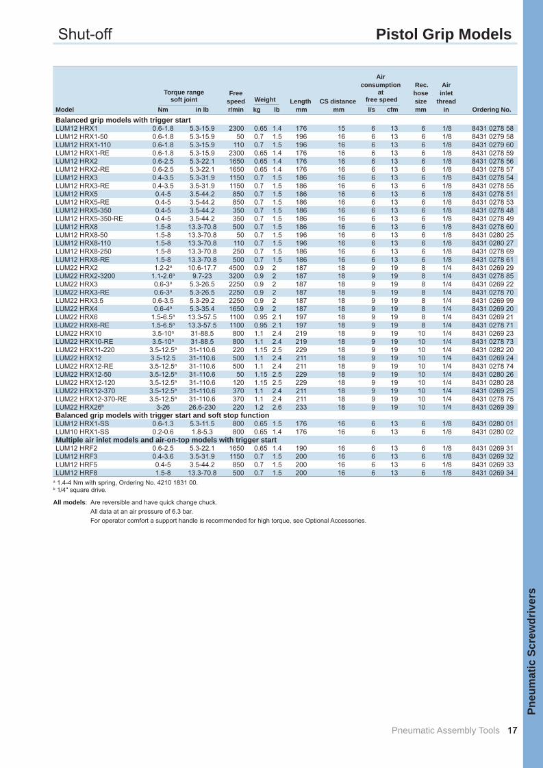
Air consumption Rec. Air Torque range Free at hose inlet soft joint speed Weight Length CS distance free speed size thread Model Nm in lb r/min kg lb mm mm l/s cfm mm in Ordering No.Balanced grip models with trigger start LUM12 HRX1 0.6-1.8 5.3-15.9 2300 0.65 1.4 176 15 6 13 6 1/8 8431 0278 58LUM12 HRX1-50 0.6-1.8 5.3-15.9 50 0.7 1.5 196 16 6 13 6 1/8 8431 0279 58LUM12 HRX1-110 0.6-1.8 5.3-15.9 110 0.7 1.5 196 16 6 13 6 1/8 8431 0279 60LUM12 HRX1-RE 0.6-1.8 5.3-15.9 2300 0.65 1.4 176 16 6 13 6 1/8 8431 0278 59LUM12 HRX2 0.6-2.5 5.3-22.1 1650 0.65 1.4 176 16 6 13 6 1/8 8431 0278 56LUM12 HRX2-RE 0.6-2.5 5.3-22.1 1650 0.65 1.4 176 16 6 13 6 1/8 8431 0278 57LUM12 HRX3 0.4-3.5 5.3-31.9 1150 0.7 1.5 186 16 6 13 6 1/8 8431 0278 54LUM12 HRX3-RE 0.4-3.5 3.5-31.9 1150 0.7 1.5 186 16 6 13 6 1/8 8431 0278 55LUM12 HRX5 0.4-5 3.5-44.2 850 0.7 1.5 186 16 6 13 6 1/8 8431 0278 51LUM12 HRX5-RE 0.4-5 3.5-44.2 850 0.7 1.5 186 16 6 13 6 1/8 8431 0278 53LUM12 HRX5-350 0.4-5 3.5-44.2 350 0.7 1.5 186 16 6 13 6 1/8 8431 0278 48LUM12 HRX5-350-RE 0.4-5 3.5-44.2 350 0.7 1.5 186 16 6 13 6 1/8 8431 0278 49LUM12 HRX8 1.5-8 13.3-70.8 500 0.7 1.5 186 16 6 13 6 1/8 8431 0278 60LUM12 HRX8-50 1.5-8 13.3-70.8 50 0.7 1.5 196 16 6 13 6 1/8 8431 0280 25LUM12 HRX8-110 1.5-8 13.3-70.8 110 0.7 1.5 196 16 6 13 6 1/8 8431 0280 27LUM12 HRX8-250 1.5-8 13.3-70.8 250 0.7 1.5 186 16 6 13 6 1/8 8431 0278 69LUM12 HRX8-RE 1.5-8 13.3-70.8 500 0.7 1.5 186 16 6 13 6 1/8 8431 0278 61LUM22 HRX2 1.2-2a 10.6-17.7 4500 0.9 2 187 18 9 19 8 1/4 8431 0269 29LUM22 HRX2-3200 1.1-2.6a 9.7-23 3200 0.9 2 187 18 9 19 8 1/4 8431 0278 85LUM22 HRX3 0.6-3a 5.3-26.5 2250 0.9 2 187 18 9 19 8 1/4 8431 0269 22LUM22 HRX3-RE 0.6-3a 5.3-26.5 2250 0.9 2 187 18 9 19 8 1/4 8431 0278 70LUM22 HRX3.5 0.6-3.5 5.3-29.2 2250 0.9 2 187 18 9 19 8 1/4 8431 0269 99LUM22 HRX4 0.6-4a 5.3-35.4 1650 0.9 2 187 18 9 19 8 1/4 8431 0269 20LUM22 HRX6 1.5-6.5a 13.3-57.5 1100 0.95 2.1 197 18 9 19 8 1/4 8431 0269 21LUM22 HRX6-RE 1.5-6.5a 13.3-57.5 1100 0.95 2.1 197 18 9 19 8 1/4 8431 0278 71LUM22 HRX10 3.5-10a 31-88.5 800 1.1 2.4 219 18 9 19 10 1/4 8431 0269 23LUM22 HRX10-RE 3.5-10a 31-88.5 800 1.1 2.4 219 18 9 19 10 1/4 8431 0278 73LUM22 HRX11-220 3.5-12.5a 31-110.6 220 1.15 2.5 229 18 9 19 10 1/4 8431 0282 20LUM22 HRX12 3.5-12.5 31-110.6 500 1.1 2.4 211 18 9 19 10 1/4 8431 0269 24LUM22 HRX12-RE 3.5-12.5a 31-110.6 500 1.1 2.4 211 18 9 19 10 1/4 8431 0278 74LUM22 HRX12-50 3.5-12.5a 31-110.6 50 1.15 2.5 229 18 9 19 10 1/4 8431 0280 26LUM22 HRX12-120 3.5-12.5a 31-110.6 120 1.15 2.5 229 18 9 19 10 1/4 8431 0280 28LUM22 HRX12-370 3.5-12.5a 31-110.6 370 1.1 2.4 211 18 9 19 10 1/4 8431 0269 25LUM22 HRX12-370-RE 3.5-12.5a 31-110.6 370 1.1 2.4 211 18 9 19 10 1/4 8431 0278 75LUM22 HRX26b 3-26 26.6-230 220 1.2 2.6 233 18 9 19 10 1/4 8431 0269 39Balanced grip models with trigger start and soft stop function LUM12 HRX1-SS 0.6-1.3 5.3-11.5 800 0.65 1.5 176 16 6 13 6 1/8 8431 0280 01LUM10 HRX1-SS 0.2-0.6 1.8-5.3 800 0.65 1.4 176 16 6 13 6 1/8 8431 0280 02Multiple air inlet models and air-on-top models with trigger start LUM12 HRF2 0.6-2.5 5.3-22.1 1650 0.65 1.4 190 16 6 13 6 1/8 8431 0269 31LUM12 HRF3 0.4-3.6 3.5-31.9 1150 0.7 1.5 200 16 6 13 6 1/8 8431 0269 32LUM12 HRF5 0.4-5 3.5-44.2 850 0.7 1.5 200 16 6 13 6 1/8 8431 0269 33LUM12 HRF8 1.5-8 13.3-70.8 500 0.7 1.5 200 16 6 13 6 1/8 8431 0269 34
a 1.4-4 Nm with spring, Ordering No. 4210 1831 00.b 1/4" square drive.
All models: Are reversible and have quick change chuck. All data at an air pressure of 6.3 bar. For operator comfort a support handle is recommended for high torque, see Optional Accessories.
Shut-off Pistol Grip Models
Am_Pneuscrewdrivers.indd 17 2012-02-06 09:29:23
18
Pneu
mat
ic S
crew
driv
ers
18 Pneumatic Assembly Tools
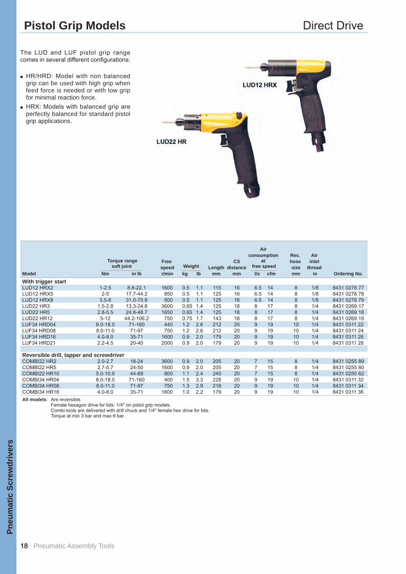
Air consumption Rec. Air Torque range Free CS at hose inlet soft joint speed Weight Length distance free speed size thread Model Nm in lb r/min kg lb mm mm l/s cfm mm in Ordering No.With trigger startLUD12 HRX2 1-2.5 8.8-22.1 1600 0.5 1.1 115 16 6.5 14 8 1/8 8431 0278 77LUD12 HRX5 2-5 17.7-44.2 850 0.5 1.1 125 16 6.5 14 8 1/8 8431 0278 78LUD12 HRX8 3.5-8 31.0-70.8 500 0.5 1.1 125 16 6.5 14 8 1/8 8431 0278 79LUD22 HR3 1.5-2.8 13.3-24.8 3600 0.65 1.4 125 18 8 17 8 1/4 8431 0269 17LUD22 HR5 2.8-5.5 24.8-48.7 1650 0.65 1.4 125 18 8 17 8 1/4 8431 0269 18LUD22 HR12 5-12 44.2-106.2 750 0.75 1.7 143 18 8 17 8 1/4 8431 0269 19LUF34 HRD04 8.0-18.0 71-160 440 1.2 2.6 212 20 9 19 10 1/4 8431 0311 22LUF34 HRD08 8.0-11.0 71-97 750 1.2 2.6 212 20 9 19 10 1/4 8431 0311 24LUF34 HRD16 4.0-8.0 35-71 1600 0.9 2.0 179 20 9 19 10 1/4 8431 0311 26LUF34 HRD21 2.2-4.5 20-40 2000 0.9 2.0 179 20 9 19 10 1/4 8431 0311 28
Reversible drill, tapper and screwdriverCOMBI22 HR2 2.0-2.7 18-24 3600 0.9 2.0 205 20 7 15 8 1/4 8431 0255 89COMBI22 HR5 2.7-5.7 24-50 1600 0.9 2.0 205 20 7 15 8 1/4 8431 0255 80COMBI22 HR10 5.0-10.0 44-89 800 1.1 2.4 240 20 7 15 8 1/4 8431 0255 62COMBI34 HR04 8.0-18.0 71-160 400 1.5 3.3 228 20 9 19 10 1/4 8431 0311 32COMBI34 HR08 8.0-11.0 71-97 750 1.3 2.9 218 20 9 19 10 1/4 8431 0311 34COMBI34 HR16 4.0-8.0 35-71 1600 1.0 2.2 179 20 9 19 10 1/4 8431 0311 36All models: Are reversible.
Female hexagon drive for bits: 1/4" on pistol grip models. Combi-tools are delivered with drill chuck and 1/4" fe male hex drive for bits. Torque at min 3 bar and max 6 bar.
Pistol Grip Models Direct Drive
The LUD and LUF pistol grip range comes in several different confi gurations:
l HR/HRD: Model with non balanced grip can be used with high grip when feed force is needed or with low grip for minimal reaction force.
l HRX: Models with balanced grip are perfectly balanced for standard pistol grip applications.
Am_Pneuscrewdrivers.indd 18 2012-02-06 09:29:24
19
Pneu
mat
ic S
crew
driv
ers
Pneumatic Assembly Tools 19
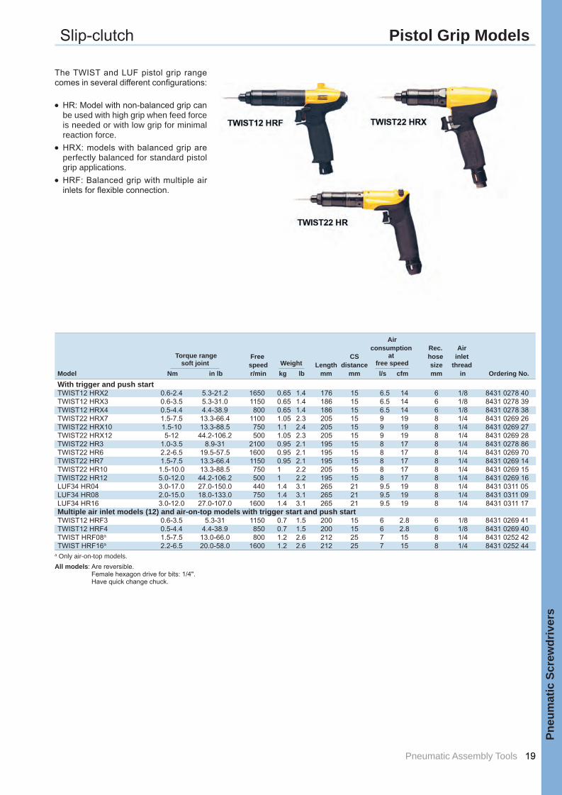
Slip-clutch Pistol Grip Models
Air consumption Rec. Air Torque range Free CS at hose inlet soft joint speed Weight Length distance free speed size thread Model Nm in lb r/min kg lb mm mm l/s cfm mm in Ordering No.With trigger and push startTWIST12 HRX2 0.6-2.4 5.3-21.2 1650 0.65 1.4 176 15 6.5 14 6 1/8 8431 0278 40TWIST12 HRX3 0.6-3.5 5.3-31.0 1150 0.65 1.4 186 15 6.5 14 6 1/8 8431 0278 39TWIST12 HRX4 0.5-4.4 4.4-38.9 800 0.65 1.4 186 15 6.5 14 6 1/8 8431 0278 38TWIST22 HRX7 1.5-7.5 13.3-66.4 1100 1.05 2.3 205 15 9 19 8 1/4 8431 0269 26TWIST22 HRX10 1.5-10 13.3-88.5 750 1.1 2.4 205 15 9 19 8 1/4 8431 0269 27TWIST22 HRX12 5-12 44.2-106.2 500 1.05 2.3 205 15 9 19 8 1/4 8431 0269 28TWIST22 HR3 1.0-3.5 8.9-31 2100 0.95 2.1 195 15 8 17 8 1/4 8431 0278 86TWIST22 HR6 2.2-6.5 19.5-57.5 1600 0.95 2.1 195 15 8 17 8 1/4 8431 0269 70TWIST22 HR7 1.5-7.5 13.3-66.4 1150 0.95 2.1 195 15 8 17 8 1/4 8431 0269 14TWIST22 HR10 1.5-10.0 13.3-88.5 750 1 2.2 205 15 8 17 8 1/4 8431 0269 15TWIST22 HR12 5.0-12.0 44.2-106.2 500 1 2.2 195 15 8 17 8 1/4 8431 0269 16LUF34 HR04 3.0-17.0 27.0-150.0 440 1.4 3.1 265 21 9.5 19 8 1/4 8431 0311 05LUF34 HR08 2.0-15.0 18.0-133.0 750 1.4 3.1 265 21 9.5 19 8 1/4 8431 0311 09LUF34 HR16 3.0-12.0 27.0-107.0 1600 1.4 3.1 265 21 9.5 19 8 1/4 8431 0311 17Multiple air inlet models (12) and air-on-top models with trigger start and push start TWIST12 HRF3 0.6-3.5 5.3-31 1150 0.7 1.5 200 15 6 2.8 6 1/8 8431 0269 41TWIST12 HRF4 0.5-4.4 4.4-38.9 850 0.7 1.5 200 15 6 2.8 6 1/8 8431 0269 40TWIST HRF08a 1.5-7.5 13.0-66.0 800 1.2 2.6 212 25 7 15 8 1/4 8431 0252 42TWIST HRF16a 2.2-6.5 20.0-58.0 1600 1.2 2.6 212 25 7 15 8 1/4 8431 0252 44
The TWIST and LUF pistol grip range comes in several different confi gurations:
l HR: Model with non-balanced grip can be used with high grip when feed force is needed or with low grip for minimal reaction force.
l HRX: models with balanced grip are perfectly balanced for standard pistol grip applications.
l HRF: Balanced grip with multiple air inlets for fl exible connection.
a Only air-on-top models. All models: Are reversible. Female hexagon drive for bits: 1/4".
Have quick change chuck.
Am_Pneuscrewdrivers.indd 19 2012-02-06 09:29:24
20
Pneu
mat
ic S
crew
driv
ers
20 Pneumatic Assembly Tools
Straight Models Shut-off
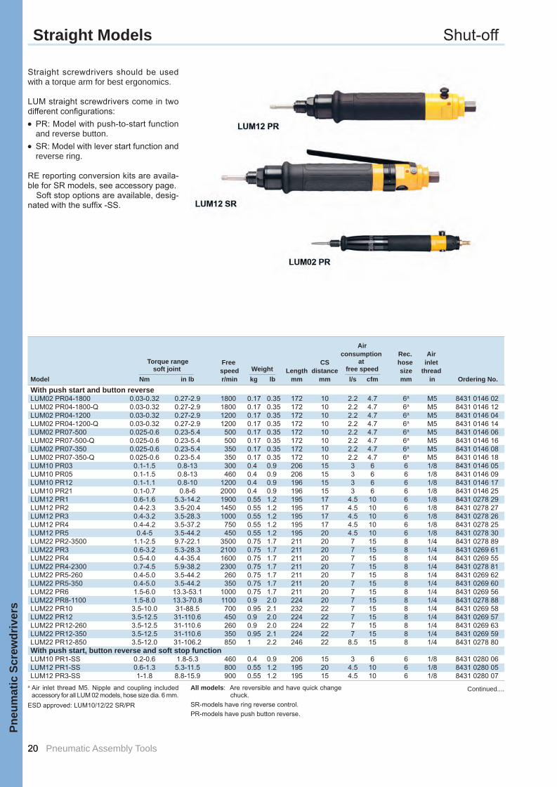
Air consumption Rec. Air Torque range Free CS at hose inlet soft joint speed Weight Length distance free speed size thread Model Nm in lb r/min kg lb mm mm l/s cfm mm in Ordering No.With push start and button reverse LUM02 PR04-1800 0.03-0.32 0.27-2.9 1800 0.17 0.35 172 10 2.2 4.7 6a M5 8431 0146 02LUM02 PR04-1800-Q 0.03-0.32 0.27-2.9 1800 0.17 0.35 172 10 2.2 4.7 6a M5 8431 0146 12LUM02 PR04-1200 0.03-0.32 0.27-2.9 1200 0.17 0.35 172 10 2.2 4.7 6a M5 8431 0146 04LUM02 PR04-1200-Q 0.03-0.32 0.27-2.9 1200 0.17 0.35 172 10 2.2 4.7 6a M5 8431 0146 14LUM02 PR07-500 0.025-0.6 0.23-5.4 500 0.17 0.35 172 10 2.2 4.7 6a M5 8431 0146 06LUM02 PR07-500-Q 0.025-0.6 0.23-5.4 500 0.17 0.35 172 10 2.2 4.7 6a M5 8431 0146 16LUM02 PR07-350 0.025-0.6 0.23-5.4 350 0.17 0.35 172 10 2.2 4.7 6a M5 8431 0146 08LUM02 PR07-350-Q 0.025-0.6 0.23-5.4 350 0.17 0.35 172 10 2.2 4.7 6a M5 8431 0146 18LUM10 PR03 0.1-1.5 0.8-13 300 0.4 0.9 206 15 3 6 6 1/8 8431 0146 05LUM10 PR05 0.1-1.5 0.8-13 460 0.4 0.9 206 15 3 6 6 1/8 8431 0146 09LUM10 PR12 0.1-1.1 0.8-10 1200 0.4 0.9 196 15 3 6 6 1/8 8431 0146 17LUM10 PR21 0.1-0.7 0.8-6 2000 0.4 0.9 196 15 3 6 6 1/8 8431 0146 25LUM12 PR1 0.6-1.6 5.3-14.2 1900 0.55 1.2 195 17 4.5 10 6 1/8 8431 0278 29LUM12 PR2 0.4-2.3 3.5-20.4 1450 0.55 1.2 195 17 4.5 10 6 1/8 8431 0278 27LUM12 PR3 0.4-3.2 3.5-28.3 1000 0.55 1.2 195 17 4.5 10 6 1/8 8431 0278 26LUM12 PR4 0.4-4.2 3.5-37.2 750 0.55 1.2 195 17 4.5 10 6 1/8 8431 0278 25LUM12 PR5 0.4-5 3.5-44.2 450 0.55 1.2 195 20 4.5 10 6 1/8 8431 0278 30LUM22 PR2-3500 1.1-2.5 9.7-22.1 3500 0.75 1.7 211 20 7 15 8 1/4 8431 0278 89LUM22 PR3 0.6-3.2 5.3-28.3 2100 0.75 1.7 211 20 7 15 8 1/4 8431 0269 61LUM22 PR4 0.5-4.0 4.4-35.4 1600 0.75 1.7 211 20 7 15 8 1/4 8431 0269 55LUM22 PR4-2300 0.7-4.5 5.9-38.2 2300 0.75 1.7 211 20 7 15 8 1/4 8431 0278 81LUM22 PR5-260 0.4-5.0 3.5-44.2 260 0.75 1.7 211 20 7 15 8 1/4 8431 0269 62LUM22 PR5-350 0.4-5.0 3.5-44.2 350 0.75 1.7 211 20 7 15 8 1/4 8431 0269 60LUM22 PR6 1.5-6.0 13.3-53.1 1000 0.75 1.7 211 20 7 15 8 1/4 8431 0269 56LUM22 PR8-1100 1.5-8.0 13.3-70.8 1100 0.9 2.0 224 20 7 15 8 1/4 8431 0278 88LUM22 PR10 3.5-10.0 31-88.5 700 0.95 2.1 232 22 7 15 8 1/4 8431 0269 58LUM22 PR12 3.5-12.5 31-110.6 450 0.9 2.0 224 22 7 15 8 1/4 8431 0269 57LUM22 PR12-260 3.5-12.5 31-110.6 260 0.9 2.0 224 22 7 15 8 1/4 8431 0269 63LUM22 PR12-350 3.5-12.5 31-110.6 350 0.95 2.1 224 22 7 15 8 1/4 8431 0269 59LUM22 PR12-850 3.5-12.0 31-106.2 850 1 2.2 246 22 8.5 15 8 1/4 8431 0278 80With push start, button reverse and soft stop function LUM10 PR1-SS 0.2-0.6 1.8-5.3 460 0.4 0.9 206 15 3 6 6 1/8 8431 0280 06LUM12 PR1-SS 0.6-1.3 5.3-11.5 800 0.55 1.2 195 20 4.5 10 6 1/8 8431 0280 05LUM12 PR3-SS 1-1.8 8.8-15.9 900 0.55 1.2 195 15 4.5 10 6 1/8 8431 0280 07
Continued....a Air inlet thread M5. Nipple and coupling included accessory for all LUM 02 models, hose size dia. 6 mm.
ESD approved: LUM10/12/22 SR/PR
All mod els: Are reversible and have quick change chuck.
SR-models have ring reverse control.PR-models have push button reverse.
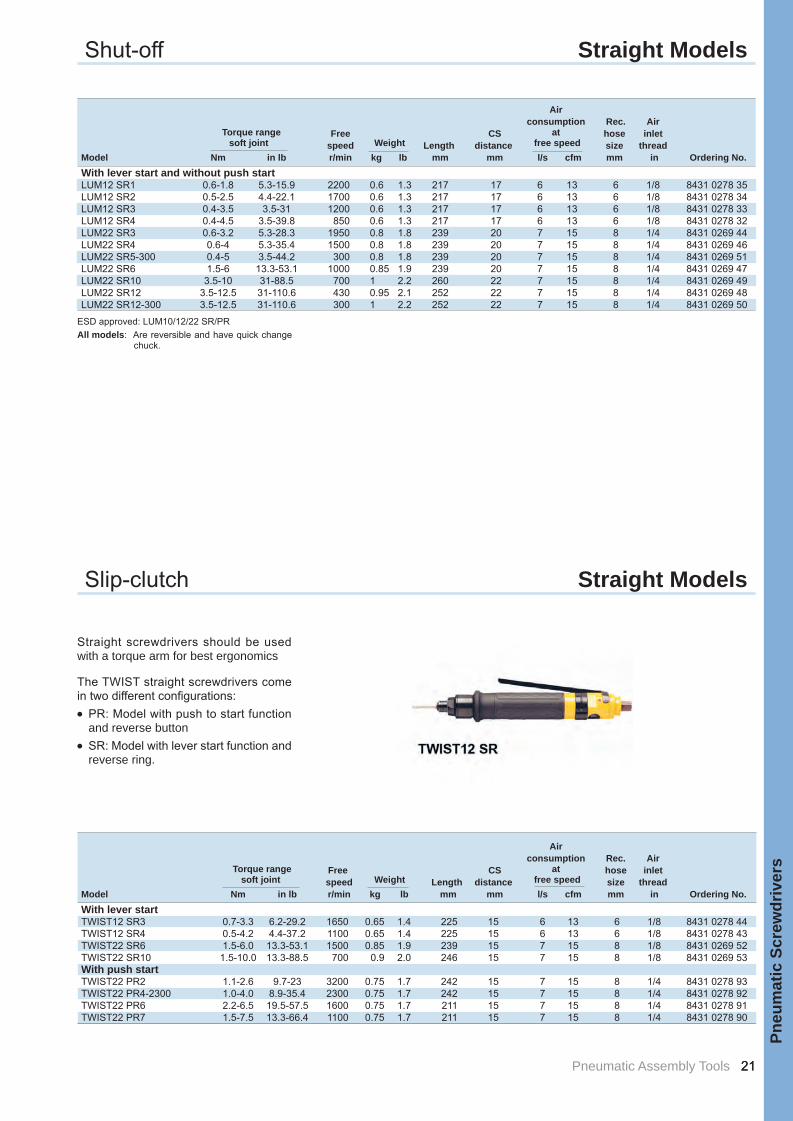
Straight screwdrivers should be used with a torque arm for best ergonomics.
LUM straight screwdrivers come in two different confi gurations:l PR: Model with push-to-start function
and reverse button.l SR: Model with lever start function and
reverse ring.
RE reporting conversion kits are availa-ble for SR models, see accessory page.
Soft stop options are available, desig-nated with the suffi x -SS.
Am_Pneuscrewdrivers.indd 20 2012-02-06 09:29:25
21
Pneu
mat
ic S
crew
driv
ers
Pneumatic Assembly Tools 21
ESD approved: LUM10/12/22 SR/PRAll mod els: Are reversible and have quick change
chuck.
Air consumption Rec. Air Torque range Free CS at hose inlet soft joint speed Weight Length distance free speed size thread Model Nm in lb r/min kg lb mm mm l/s cfm mm in Ordering No.With lever start and without push startLUM12 SR1 0.6-1.8 5.3-15.9 2200 0.6 1.3 217 17 6 13 6 1/8 8431 0278 35LUM12 SR2 0.5-2.5 4.4-22.1 1700 0.6 1.3 217 17 6 13 6 1/8 8431 0278 34LUM12 SR3 0.4-3.5 3.5-31 1200 0.6 1.3 217 17 6 13 6 1/8 8431 0278 33LUM12 SR4 0.4-4.5 3.5-39.8 850 0.6 1.3 217 17 6 13 6 1/8 8431 0278 32LUM22 SR3 0.6-3.2 5.3-28.3 1950 0.8 1.8 239 20 7 15 8 1/4 8431 0269 44LUM22 SR4 0.6-4 5.3-35.4 1500 0.8 1.8 239 20 7 15 8 1/4 8431 0269 46LUM22 SR5-300 0.4-5 3.5-44.2 300 0.8 1.8 239 20 7 15 8 1/4 8431 0269 51LUM22 SR6 1.5-6 13.3-53.1 1000 0.85 1.9 239 20 7 15 8 1/4 8431 0269 47LUM22 SR10 3.5-10 31-88.5 700 1 2.2 260 22 7 15 8 1/4 8431 0269 49LUM22 SR12 3.5-12.5 31-110.6 430 0.95 2.1 252 22 7 15 8 1/4 8431 0269 48LUM22 SR12-300 3.5-12.5 31-110.6 300 1 2.2 252 22 7 15 8 1/4 8431 0269 50
Shut-off Straight Models
Slip-clutch Straight Models
Air consumption Rec. Air Torque range Free CS at hose inlet soft joint speed Weight Length distance free speed size thread Model Nm in lb r/min kg lb mm mm l/s cfm mm in Ordering No.With lever startTWIST12 SR3 0.7-3.3 6.2-29.2 1650 0.65 1.4 225 15 6 13 6 1/8 8431 0278 44TWIST12 SR4 0.5-4.2 4.4-37.2 1100 0.65 1.4 225 15 6 13 6 1/8 8431 0278 43TWIST22 SR6 1.5-6.0 13.3-53.1 1500 0.85 1.9 239 15 7 15 8 1/8 8431 0269 52TWIST22 SR10 1.5-10.0 13.3-88.5 700 0.9 2.0 246 15 7 15 8 1/8 8431 0269 53With push startTWIST22 PR2 1.1-2.6 9.7-23 3200 0.75 1.7 242 15 7 15 8 1/4 8431 0278 93TWIST22 PR4-2300 1.0-4.0 8.9-35.4 2300 0.75 1.7 242 15 7 15 8 1/4 8431 0278 92TWIST22 PR6 2.2-6.5 19.5-57.5 1600 0.75 1.7 211 15 7 15 8 1/4 8431 0278 91TWIST22 PR7 1.5-7.5 13.3-66.4 1100 0.75 1.7 211 15 7 15 8 1/4 8431 0278 90
Straight screwdrivers should be used with a torque arm for best ergonomics
The TWIST straight screwdrivers come in two different confi gurations:l PR: Model with push to start function
and reverse buttonl SR: Model with lever start function and
reverse ring.
Am_Pneuscrewdrivers.indd 21 2012-02-06 09:29:26
22
Pneu
mat
ic S
crew
driv
ers
22 Pneumatic Assembly Tools
Angle Models Shut-off
Angle Air Angle head consumption Rec. Air Torque range Free head center at hose inlet soft joint speed Weight Length height to side free speed size thread Model Nm in lb r/min kg lb mm mm mm l/s cfm mm in Ordering No.LTV009 R07-6-230 0.3-7 2.6-61.9 230 0.8 1.8 266 25 9 6 13 6 1/8 8431 0279 18LTV009 R035-6 0.4-3.5 3.5-31 1100 0.7 1.5 266 25 9 6 13 6 1/8 8431 0278 05LTV009 R035-42 0.4-3.5 3.5-31 1100 0.7 1.5 266 25 9 6 13 6 1/8 8431 0278 04LTV009 R035-Q 0.4-3.5 3.5-31 1100 0.7 1.5 266 25 9 6 13 6 1/8 8431 0278 03LTV009 R05-6 0.4-5 3.5-44.2 850 0.7 1.5 266 25 9 6 13 6 1/8 8431 0278 08LTV009 R05-42 0.4-5 3.5-44.2 850 0.7 1.5 266 25 9 6 13 6 1/8 8431 0278 07LTV009 R05-Q 0.4-5 3.5-44.2 850 0.7 1.5 266 25 9 6 13 6 1/8 8431 0278 06LTV009 R025-6 0.6-2.5 5.3-22.1 1650 0.7 1.5 266 25 9 6 13 6 1/8 8431 0278 02LTV009 R025-42 0.6-2.5 5.3-22.1 1650 0.7 1.5 266 25 9 6 13 6 1/8 8431 0278 01LTV009 R025-Q 0.6-2.5 5.3-22.1 1650 0.7 1.5 266 25 9 6 13 6 1/8 8431 0278 00LTV009 R03-10 0.7-3 6.2-26.5 1400 0.7 1.5 266 25 9 6 13 6 1/8 8431 0278 23LTV009 R07-6 1.1-7 9.7-61.9 500 0.7 1.5 266 28.5 11 6 13 6 1/8 8431 0278 11LTV009 R07-42 1.1-7 9.7-61.9 500 0.7 1.5 266 25 9 6 13 6 1/8 8431 0278 10LTV009 R07-Q 1.1-7 9.7-61.9 500 0.7 1.5 266 25 9 6 13 6 1/8 8431 0278 09LTV009 R08-6-200 1.3-9 11.5-79.6 200 0.7 1.5 266 28.5 11 6 13 6 1/8 8431 0278 24LTV009 R08-6-200-B 1.3-9 11.5-79.6 200 0.8 1.8 266 27.6 11 6 13 6 1/8 8431 0278 31LTV009 R09-6 1.3-9 11.5-79.6 430 0.7 1.5 266 28.5 11 6 13 6 1/8 8431 0278 17LTV009 R09-10 1.3-9 11.5-79.6 430 0.7 1.5 266 28.5 11 6 13 6 1/8 8431 0278 13LTV009 R09-42 1.3-9 11.5-79.6 430 0.7 1.5 266 28.5 11 6 13 6 1/8 8431 0278 15LTV009 R09-Q 1.3-9 11.5-79.6 430 0.7 1.5 266 28.5 11 6 13 6 1/8 8431 0278 12LTV009 R09-42M 1.3-9 11.5-79.6 430 0.7 1.5 266 28.5 11 6 13 6 1/8 8431 0278 16LTV009 R11-6 1.3-11 11.5-97.3 320 0.8 1.8 266 28.5 11 6 13 6 1/8 8431 0278 22LTV009 R11-10 1.3-11 11.5-97.3 320 0.8 1.8 266 28.5 11 6 13 6 1/8 8431 0278 20LTV009 R11-42 1.3-11 11.5-97.3 320 0.8 1.8 266 28.5 11 6 13 6 1/8 8431 0278 21LTV009 R11-Q 1.3-11 11.5-97.3 320 0.8 1.8 266 28.5 11 6 13 6 1/8 8431 0278 19LTV009 R08-FS-10 1.5-8 13.3-70.8 340 1.1 2.4 261 23.5 13.5 6 13 6 1/8 8431 0632 11LTV009 R13-FS-10 4-13 35.4-115.1 160 1.1 2.4 261 23.5 13.5 6 13 6 1/8 8431 0632 10LTV18 R07-6 3.5-7 31-61 700 1.2 2.6 290 28.5 10 6 13 6 1/4 8431 0326 72LTV18 R07-42 3.5-7 31-61 700 1.2 2.6 290 28.5 10 6 13 6 1/4 8431 0326 61LTV18 R07-Q 3.5-7 31-61 700 1.2 2.6 290 28.5 10 6 13 6 1/4 8431 0326 76LTV18 R15-6 6.0-15 53-132 360 1.2 2.6 308 28 11 7 15 8 1/4 8431 0326 55LTV18 R15-42 6.0-15 53-132 360 1.2 2.6 308 28 11 7 15 8 1/4 8431 0326 54LTV18 R15-10 6.0-15 53-132 360 1.2 2.6 308 28 11 7 15 8 1/4 8431 0326 56LTV18 R15-Q 6.0-15 53-132 360 1.2 2.6 308 28 11 7 15 8 1/4 8431 0326 58
ESD approved: LTV009.All models: Are reversible.
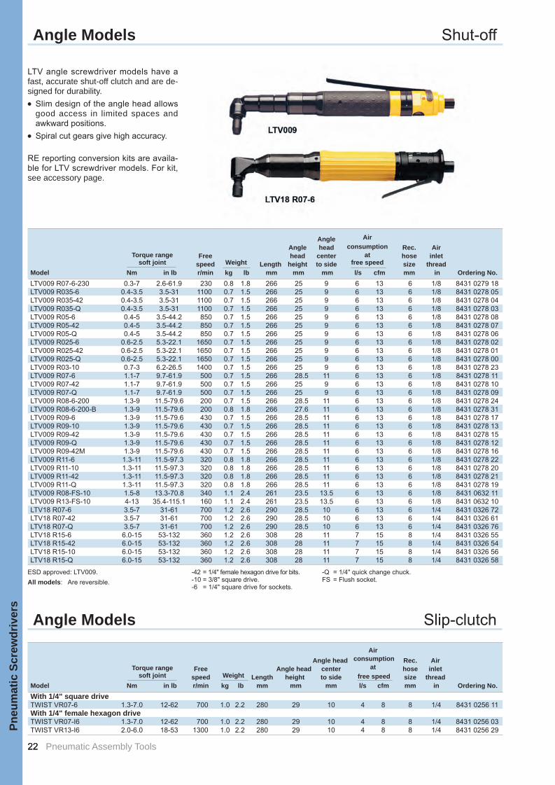
LTV angle screwdriver models have a fast, accurate shut-off clutch and are de-signed for durability. l Slim design of the angle head allows
good access in limited spaces and awkward positions.
l Spiral cut gears give high accuracy.
RE reporting conversion kits are availa-ble for LTV screwdriver models. For kit, see accessory page.
Air Angle head consumption Rec. Air Torque range Free Angle head center at hose inlet soft joint speed Weight Length height to side free speed size thread Model Nm in lb r/min kg lb mm mm mm l/s cfm mm in Ordering No.With 1/4" square driveTWIST VR07-6 1.3-7.0 12-62 700 1.0 2.2 280 29 10 4 8 8 1/4 8431 0256 11With 1/4" female hexagon driveTWIST VR07-I6 1.3-7.0 12-62 700 1.0 2.2 280 29 10 4 8 8 1/4 8431 0256 03TWIST VR13-I6 2.0-6.0 18-53 1300 1.0 2.2 280 29 10 4 8 8 1/4 8431 0256 29
Angle Models Slip-clutch
-42 = 1/4" female hexagon drive for bits. -10 = 3/8" square drive. -6 = 1/4" square drive for sockets.
-Q = 1/4" quick change chuck. FS = Flush socket.
Am_Pneuscrewdrivers.indd 22 2012-02-06 09:29:27
23
Pneu
mat
ic S
crew
driv
ers
Pneumatic Assembly Tools 23
Screwdrivers Accessories
Torque arms Installation ESD approvedDesignation Exhaust hose Support handle ESD hose adapters proposal pistol handle
LUM12 HRX/HRF 4210 2052 00 4110 1355 92 8202 0501 06 – 8202 1180 67 4210 3616 04 LUM22 HR 3, 4, 6 4210 2052 00 4110 1355 92 8202 0501 10 – 8202 1180 77 4210 4337 04 LUM22 HR 10, 12 4210 2052 00 4110 1355 93 8202 0501 10 – 8202 1180 77 4210 4337 04 LUM22 HRX 3, 4, 6 4210 2052 00 4110 1355 92 8202 0501 10 – 8202 1180 77 4210 3616 04 LUM12 SR 4210 2052 00 – 8202 0501 06 4390 1735 52 8202 1180 67 – LUM12 PR 4210 2052 00 – 8202 0501 06 4390 1735 53 8202 1180 67 – LUM22 SR 4210 2053 00 – 8202 0501 10 4390 1735 51 8202 1180 77 – LUM22 PR 4210 2053 00 – 8202 0501 10 4390 1735 54 8202 1180 77 – LTV009 4210 2052 00 – 8202 0501 06 – 8202 1180 67 – LUM32 HR 4210 2052 00 4110 1355 94 8202 0501 10 – 8202 1180 77 4210 4337 04LUF34 4210 2053 00 4110 1355 82 8202 0501 10 – 8202 1180 77 –
Model Ordering No.
LUM12 HRF 4210 3624 99LUM12 SR 4210 4137 90LUM22 SR 4210 2057 80LTV009 4210 4137 90LTV18 4210 4023 90
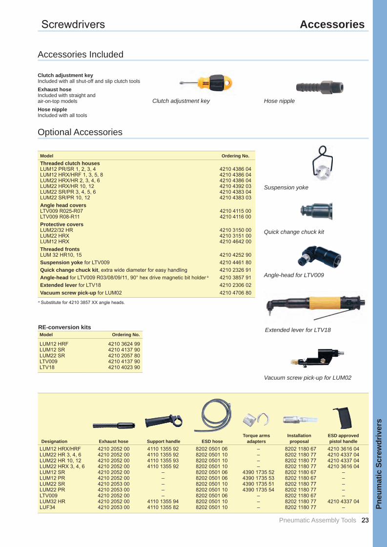
Model Ordering No.Threaded clutch housesLUM12 PR/SR 1, 2, 3, 4 4210 4386 04LUM12 HRX/HRF 1, 3, 5, 8 4210 4386 04LUM22 HRX/HR 2, 3, 4, 6 4210 4386 04LUM22 HRX/HR 10, 12 4210 4392 03LUM22 SR/PR 3, 4, 5, 6 4210 4383 04LUM22 SR/PR 10, 12 4210 4383 03Angle head coversLTV009 R025-R07 4210 4115 00LTV009 R08-R11 4210 4116 00Protective coversLUM22/32 HR 4210 3150 00LUM22 HRX 4210 3151 00LUM12 HRX 4210 4642 00Threaded frontsLUM 32 HR10, 15 4210 4252 90Suspension yoke for LTV009 4210 4461 80Quick change chuck kit, extra wide diameter for easy handling 4210 2326 91Angle-head for LTV009 R03/08/09/11, 90° hex drive magnetic bit holder a 4210 3857 91Extended lever for LTV18 4210 2306 02Vacuum screw pick-up for LUM02 4210 4706 80
Clutch adjustment keyIncluded with all shut-off and slip clutch toolsExhaust hoseIncluded with straight andair-on-top modelsHose nippleIncluded with all tools
Accessories Included
Optional Accessories
Suspension yoke
RE-conversion kits
a Substitute for 4210 3857 XX angle heads.
Vacuum screw pick-up for LUM02
Clutch adjustment key Hose nipple
Quick change chuck kit
Angle-head for LTV009
Extended lever for LTV18
Am_Pneuscrewdrivers.indd 23 2012-02-06 09:29:41
24
Pneu
mat
ic S
crew
driv
ers
24 Pneumatic Assembly Tools
Accessories Screwdrivers
Model Ordering No.LUM10 PR 4081 0070 90LUM12 HRX, HRF 4081 0247 90LUM12 SR 4081 0254 90LUM12 PR 4081 0250 90LUM22 HR/HRX 3, 4, 6, 12 4081 0281 90LUM22 HR/HRX 10 4081 0282 90LUM22 PR/SR 3, 4, 6, 12 4081 0284 90LUM22 PR/SR 10 4081 0285 90LUM25 HRF 4081 0075 90LUM32 HR 4081 0316 90LUF34 HR 4081 0086 90TWIST HRF 4081 0079 90TWIST VR 4081 0078 90TWIST HR 3, 7, 12 4081 0291 90TWIST HR 6 4081 0281 90TWIST HR 10 4081 0292 90TWIST12 HRX 2, 3, 4 4081 0247 90TWIST22 HRX 2-3200, 7, 12 4081 0296 90TWIST22 HRX 10 4081 0295 90LTV009 4081 0248 90LTV18 4081 0085 90
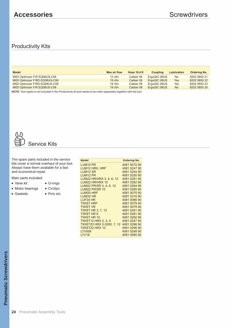
Service Kits
The spare parts included in the service kits cover a normal overhaul of your tool. Always have them available for a fast and economical repair.
Main parts included:l Vane kit l O-ringsl Motor bearings l Circlipsl Gaskets l Pins etc.
Productivity Kits
Model Maxairflow Hose16.4ft Coupling Lubrication OrderingNo.MIDI Optimizer F/R EQ08US-C06 12 cfm Cablair 06 ErgoQIC 08US No 8202 0850 21MIDI Optimizer F/RD EQ08US-C06 19 cfm Cablair 06 ErgoQIC 08US Yes 8202 0850 22MIDI Optimizer F/RD EQ08US-C08 19 cfm Cablair 08 ErgoQIC 08US Yes 8202 0850 23MIDI Optimizer F/R EQ08US-C08 19 cfm Cablair 08 ErgoQIC 08US No 8202 0850 24
NOTE: Tool nipple is not included in the Productivity kit and needs to be order separately together with the tool.
Am_Pneuscrewdrivers.indd 24 2012-02-06 09:29:42
Impa
ct W
renc
hes
Pneumatic Assembly Tools 25
Introduction – Impact Wrenches
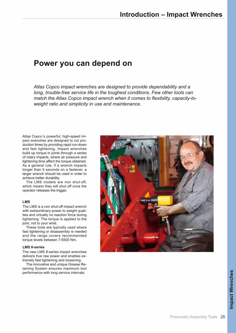
Power you can depend on
Atlas Copco´s powerful, high-speed im-pact wrenches are designed to cut pro-duction times by providing rapid run-down and fast tightening. Impact wrenches build up torque in joints through a series of rotary impacts, where air pressure and tightening time affect the torque obtained. As a general rule, if a wrench impacts longer than 5 seconds on a fastener, a larger wrench should be used in order to achieve better durability.
The LMS models are non shut-off, which means they will shut off once the operator releases the trigger.
LMSThe LMS is a non shut-off impact wrench with extraordinary power to weight quali-ties and virtually no reaction force during tightening. The torque is applied to the joint, not to your wrist.
These tools are typically used where fast tightening or disassembly is needed and the range covers recommended torque levels between 7-5500 Nm.
LMS 8-seriesThe new LMS 8-series impact wrenches delivers true raw power and enables ex-tremely fast tightening and loosening.
The innovative and unique Grease Re-taining System ensures maximum tool performance with long service intervals.
Atlas Copco impact wrenches are designed to provide dependability and a long, trouble-free service life in the toughest conditions. Few other tools can match the Atlas Copco impact wrench when it comes to flexibility, capacity-to-weight ratio and simplicity in use and maintenance.
Im
pact
Wre
nche
s
26 Pneumatic Assembly Tools
8.8
10.9
12.9
=
=
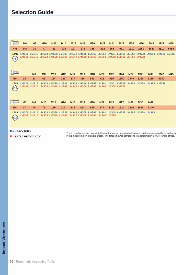
M6 M8 M10 M12 M14 M16 M18 M20 M22 M24 M27 M30 M36 M42 M45 M48
Nm 9.8 24 47 81 128 197 275 385 518 665 961 1310 2280 3640 4510 5450
LMS LMS08 LMS18 LMS18 LMS28 LMS38 LMS38 LMS48 LMS58 LMS58 LMS61 LMS61 LMS68 LMS88 LMS88 LMS88 LMS88 LMS08 LMS18 LMS28 LMS38 LMS38 LMS48 LMS58 LMS58 LMS58 LMS68 LMS68 LMS68 LMS88
M6 M8 M10 M12 M14 M16 M18 M20 M22 M24 M27 M30 M36 M42 M45 Nm 14 33 65 114 181 277 386 541 728 935 1350 1840 3210 5110 6340
LMS LMS08 LMS18 LMS28 LMS28 LMS38 LMS38 LMS48 LMS58 LMS61 LMS61 LMS68 LMS88 LMS88 LMS88 LMS88 LMS18 LMS18 LMS28 LMS38 LMS48 LMS48 LMS58 LMS68 LMS68 LMS68 LMS88
M6 M8 M10 M12 M14 M16 M18 M20 M22 M24 M27 M30 M36 M42
Nm 17 40 79 136 217 333 463 649 874 1120 1620 2210 3850 6140
LMS LMS08 LMS18 LMS28 LMS28 LMS38 LMS48 LMS58 LMS61 LMS61 LMS68 LMS88 LMS88 LMS88 LMS88 LMS18 LMS18 LMS28 LMS38 LMS48 LMS58 LMS68 LMS68 LMS68 LMS88
Selection Guide
HEAVY DUTY
EXTRA HEAVY DUTYThe torque figures are normal tightening torque for untreated oil-smeared and rust-protected bolts and nuts in the most common strength grades. The torque figures correspond to approximately 63% of tensile stress.
Am_Impact wrenches.indd 26 2012-02-06 09:34:50
Impa
ct W
renc
hes
Pneumatic Assembly Tools 27
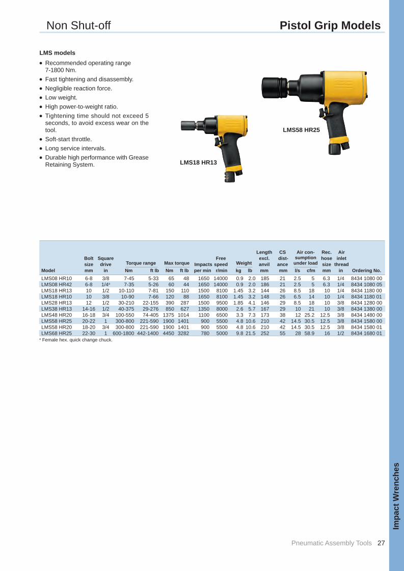
LMS58 HR25
LMS18 HR13
Length CS Air con- Rec. Air Bolt Square Free excl. dist- sumption hose inlet size drive Torque range Max torque Impacts speed Weight anvil ance under load size thread Model mm in Nm ft lb Nm ft lb per min r/min kg lb mm mm l/s cfm mm in Ordering No.LMS08 HR10 6-8 3/8 7-45 5-33 65 48 1650 14000 0.9 2.0 185 21 2.5 5 6.3 1/4 8434 1080 00LMS08 HR42 6-8 1/4a 7-35 5-26 60 44 1650 14000 0.9 2.0 186 21 2.5 5 6.3 1/4 8434 1080 05LMS18 HR13 10 1/2 10-110 7-81 150 110 1500 8100 1.45 3.2 144 26 8.5 18 10 1/4 8434 1180 00LMS18 HR10 10 3/8 10-90 7-66 120 88 1650 8100 1.45 3.2 148 26 6.5 14 10 1/4 8434 1180 01LMS28 HR13 12 1/2 30-210 22-155 390 287 1500 9500 1.85 4.1 146 29 8.5 18 10 3/8 8434 1280 00LMS38 HR13 14-16 1/2 40-375 29-276 850 627 1350 8000 2.6 5.7 167 29 10 21 10 3/8 8434 1380 00LMS48 HR20 16-18 3/4 100-550 74-405 1375 1014 1100 6500 3.3 7.3 173 38 12 25.2 12.5 3/8 8434 1480 00LMS58 HR25 20-22 1 300-800 221-590 1900 1401 900 5500 4.8 10.6 210 42 14.5 30.5 12.5 3/8 8434 1580 00LMS58 HR20 18-20 3/4 300-800 221-590 1900 1401 900 5500 4.8 10.6 210 42 14.5 30.5 12.5 3/8 8434 1580 01LMS68 HR25 22-30 1 600-1800 442-1400 4450 3282 780 5000 9.8 21.5 252 55 28 58.9 16 1/2 8434 1680 01
Non Shut-off Pistol Grip Models
a Female hex. quick change chuck.
LMS modelsl Recommended operating range 7-1800 Nm.l Fast tightening and disassembly.l Negligible reaction force.l Low weight.l High power-to-weight ratio.l Tightening time should not exceed 5
seconds, to avoid excess wear on the tool.
l Soft-start throttle.l Long service intervals.l Durable high performance with Grease
Retaining System.
Am_Impact wrenches.indd 27 2012-02-06 09:35:11

Im
pact
Wre
nche
s
28 Pneumatic Assembly Tools
LMS08 SR10
LMS88 GIR38
LMS68 GIR25
Length CS Air con- Rec. Air Bolt Square Free excl. dist- sumption hose inlet size drive Torque range Max torque Impacts speed Weight anvil ance under load size thread Model mm in Nm ft lb Nm ft lb per min r/min kg lb mm mm l/s cfm mm in Ordering No.LMS08 SR42 6-8 1/4a 7-35 5-26 60 44 1650 12500 0.85 1.9 185 20 2.5 5 6.3 1/4 8434 1081 06LMS08 SR10 6-8 3/8 7-45 5-33 65 48 1650 12500 0.85 1.9 184 20 2.5 5 6.3 1/4 8434 1081 11LMS68 GIR25 22-30 1 600-1800 442-1400 4450 3282 780 5000 9.6 21.1 339 55 28 58.9 16 1/2 8434 1680 00LMS68 GOR25 22-30 1 600-1800 442-1400 4450 3282 780 5000 9.6 21.1 339 55 28 58.9 16 1/2 8434 1680 02LMS68 GIR S5 22-30 1 5/8b 600-1800 442-1400 4450 3282 780 5000 9.6 21.1 339 55 28 58.9 16 1/2 8434 1680 05LMS68 GOR S5 22-30 1 5/8b 600-1800 442-1400 4450 3282 780 5000 9.6 21.1 339 55 28 58.9 16 1/2 8434 1680 10LMS88 GIR38 30-42 1 1/2 1000-5500 737-4054 10000 7370 540 3800 15.0 33.0 381 63.5 33 69.4 16 1/2 8434 1880 00LMS88 GOR38 30-42 1 1/2 1000-5500 737-4054 10000 7370 540 3800 15.0 33.0 381 63.5 33 69.4 16 1/2 8434 1880 01LMS88 GIR S5 30-42 1 5/8b 1000-5500 737-4054 10000 7370 540 3800 15.0 33.0 381 63.5 33 69.4 16 1/2 8434 1880 05LMS88 GOR S5 30-42 1 5/8b 1000-5500 737-4054 10000 7370 540 3800 15.0 33.0 381 63.5 33 69.4 16 1/2 8434 1880 10
a Female hex. quick change chuck. b Spline drive No. 5.GOR = Outside trigger.GIR = Inside trigger.
Straight Models Non Shut-off
LMS modelsl Recommended operating range 7-5500 Nm.l Fast tightening and disassembly.l Negligible reaction force.l Low weight.l High power-to-weight ratio.l Soft-start throttle.l Tightening time should not exceed 5
seconds, to avoid excess wear on the tool.
l Long service intervals.l Durable high performance with grease
retaining system.
Am_Impact wrenches.indd 28 2012-02-06 09:35:38

Impa
ct W
renc
hes
Pneumatic Assembly Tools 29
Optional Accessories
Accessories
Whip hose
Model Ordering No.
LMS08 HR10/SR10 8202 1350 20LMS18 HR10/13, LMS28/38 HR13, LMS48/58 HR20, LMS58 HR25 8202 1350 22LMS68 HR25, LMS68/88 GIR, LMS68/88 GOR 8202 1350 24
Model Ordering No.
LMS08 HR10/SR10, LMS18 HR10/13, LMS28/38 HR13, Not necessaryLMS48/58 HR20, LMS58 HR25
LMS68 HR25, LMS68/88 GIR, LMS68/88 GOR 8202 1180 28
MultiFlex Swivel
Whip hose
Productivity Kits
The spare parts included in the service kits cover a nor mal overhaul of your tool. Always have them available for a fast and economical rep air.
Main parts included:l Gaskets l O-ringsl Circlips l Pins etc.
Model Service kit
LMS08 4081 0465 00LMS18 4081 0466 00LMS28 4081 0467 00LMS38 4081 0468 00LMS48 4081 0461 00LMS58 4081 0445 00LMS68 4081 0442 00LMS88 4081 0443 00
Service Kits
MultiFlex Swivel
Model Max air fl ow Hose 16.4 ft Coupling Lubrication Ordering No.For small impact wrenches and pulse toolsMIDI Optimizer F/RD EP EQ08US-C08 19 cfm Cablair 08 ErgoQIC 08US Yes 8202 0850 45
For 1/2" impact wrenches and pulse tools MIDI Optimizer F/RD EP EQQ10US-C10 34 cfm Cablair 10 ErgoQIC 10US Yes 8202 0850 46
For impact wrenches and pulse toolsMIDI Optimizer F/RD EP EQ10US-C13 50 cfm Cablair 13 ErgoQIC 10US Yes 8202 0850 47MIDI Optimizer F/RD EP EQ10US-T13 65 cfm Turbo 13 ErgoQIC 10US Yes 8202 0850 48
NOTE: Tool nipple is not included in the Productivity kit and needs to be order separately together with the tool.
Am_Impact wrenches.indd 29 2012-02-06 09:35:41
30 Pneumatic Assembly Tools
Hyd
raul
ic Im
puls
e N
utru
nner
s
30
Introduction – ErgoPulse
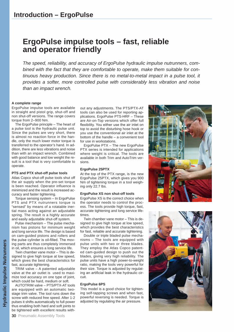
ErgoPulse impulse tools – fast, reliable and operator friendly
A complete range ErgoPulse impulse tools are available in straight and pistol grip, shut-off and non shut-off versions. The range covers torque from 2–900 Nm.
The ErgoPulse principle – The heart of a pulse tool is the hydraulic pulse unit. Since the pulses are very short, there is almost no reaction force in the han-dle, only the much lower motor torque is transferred to the operator’s hand. In ad-dition, there are less vibrations and noise than with an impact wrench. Combined with good balance and low weight the re-sult is a tool that is very comfortable to operate.
PTS and PTX shut-off pulse tools Atlas Copco shut-off pulse tools shut off the air supply when the pre-set torque is been reached. Operator influence is minimized and the result is increased ac-curacy and faster tightening.
Torque sensing system – In ErgoPulse PTS and PTX nutrunners torque is “sensed” by means of a rotatable iner-tial mass acting against an adjustable spring. The result is a highly accurate and easily adjustable shut-off system.
Pulse mechanism – The pulse mecha-nism has pistons for minimum weight and long service life. The design is based on cam-guided pistons and rollers and the pulse cylinder is oil-filled. The mov-ing parts are thus completely immersed in oil, which ensures a long service life.
Twin chamber vane motor – This is de-signed to give high torque at low speed, which gives the best characteristics for fast, accurate tightening.
TRIM valve – A patented adjustable valve at the air outlet is used to maxi-mize tool accuracy on one type of joint, which could be hard, medium or soft.
AUTOTRIM valve – PTS/PTX-AT tools are equipped with an automatic two-stage trim valve. The tool runs down the screw with reduced free speed. After 1-2 pulses it shifts automatically to full power thus enabling both hard and soft joints to be tightened with excellent results with-
The speed, reliability, and accuracy of ErgoPulse hydraulic impulse nutrunners, com-bined with the fact that they are comfortable to operate, make them suitable for con-tinuous heavy production. Since there is no metal-to-metal impact in a pulse tool, it provides a softer, more controlled pulse with considerably less vibration and noise than an impact wrench.
out any adjustments. The PTS/PTX-AT tools can also be used for reporting ap-plications. ErgoPulse PTS-HRF – These are Air-on-Top versions which offer full flexibility. You either use the air inlet on top to avoid the disturbing hose hook or you use the conventional air inlet at the bottom of the handle – a convenient tool for use in workstations.
ErgoPulse PTX – The new ErgoPulse PTX series is intended for applications where weight is critical. The tools are available in both Trim and AutoTrim ver-sions.
ErgoPulse 25PTXAt the top of the PTX range, is the new ErgoPulse 25PTX, which gives you 900 Nm of tightening torque in a tool weigh-ing only 22.7 lbs.
ErgoPulse XS non shut-off toolsErgoPulse XS is the correct choice when the operator needs to control the proc-ess. The tools provide high torque, fast, accurate tightening and long service life-times.
Twin chamber vane motor – This is de-signed to give high torque at low speed, which provides the best characteristics for fast, reliable and accurate tightening.
Double or triple bladed pulse mecha-nisms – The tools are equipped with pulse units with two or three blades. They employ the Atlas Copco patent-ed cam-guided design to push out the blades, giving very high reliability. The pulse units have a high power-to-weight ratio, making the tools very powerful for their size. Torque is adjusted by regulat-ing an artificial leak in the hydraulic cir-cuit.
ErgoPulse 6PS This model is a good choice for tighten-ing self-tapping screws and when fast, powerful reversing is needed. Torque is adjusted by regulating the air pressure.
Am_ErgoPulse.indd 30 2012-02-06 09:54:55

Hyd
raul
ic Im
puls
e N
utru
nner
s
Pneumatic Assembly Tools 3131
M16
M14
M12
M10
M8
M6
14
8*
85
150
30*
55
18*
35
10*
22
5PTS14PTS12PTS10PTS
8PTS7PTS6PTS
M20
18PTS
50
90
5PTX
125
250
8*
19
16
32
225
410
22*
45
19
9*13*
31
5PTX 7PTX6PTX 8PTX
8.8
50
80
7PTX9PTX
4PTX 6PTX
M5
8PTX
40
70
11PTX
70
110
3PTX4PTX
3PTX
9
4*
225
450
13PTX 19PTX15PTX
125
250
85
150
15
6*
2*
5
30
55
9
4*
2*
5
25PTX
M24
M27
450
900
8.8
M20
M16 M14
M12
M10
M8
M5
M6
M4
240
160
400
300
70
50
20
10*
52
30*
31
20*
10*
20
52
30*
110
65
160
110
12
5
28 31
20*
6XS 7XS 8XS 20XS 16XS 14XS 10XS6XS 7XS 8XS 12XS 5XS 6PS
Selection Guide
* For tools with quick change chuck, see technical data.
Screw size
TorqueNm
3/8" square drive 1/2" square drive3/4" square
drive
Straight Pistol grip models models
3/8" square drive
Torque Nm
Straight models Pistol grip models
* For tools with quick change chuck, see technical data.
Screw size
3/8" square drive3/8" square drive 1/2" square drive 3/4" square
drive1/4" quick
change chuck
1" s
quar
e dr
ive
The ErgoPulse PTS and PTX tools can be adjusted within a wide torque range by simply setting the spring force that counteracts the inertia body. Torque should preferably be checked with a hand torque wrench. Electronic monitoring with an in-line transducer is possible but should be verified with a manual hand torque wrench to avoid measuring errors due to the extremely short pulse sequence.
The size of tool is determined on the basis of torque and/or bolt dimension. Torque should preferably be checked with a hand torque wrench. Electronic monitoring with an in-line transducer is possible but should be verified with a manual hand torque wrench to avoid measuring errors due to the extremely short pulse sequence.
EP XS/PS Non shut-off models
EP PTS/PTX Shut-off models
Am_ErgoPulse.indd 31 2012-02-06 09:54:56

32 Pneumatic Assembly Tools
Hyd
raul
ic Im
puls
e N
utru
nner
s
32
Pistol Grip Models Shut-off
Air con- Rec. Air Bolt Square Free CS sumption hose inlet size drive Torque rangea speed Weight Length distance under load size thread Model mm in Nm ft lb r/min kg lb mm mm l/s cfm mm in Ordering No.TRIM-RE EP3PTX5 HR42-RE M4-M5 1/4b 2-5 1.6-4 5000c 0.8 1.7 154 21 4 9 8 1/4 8431 0375 51EP4PTX9 HR10-RE M5 3/8 4-9 3-7 3400d 0.9 1.9 164 22 4 9 8 1/4 8431 0375 54EP4PTX9 HR42-RE M5 1/4b 4-9 3-7 3400d 0.9 1.9 164 22 4 9 8 1/4 8431 0375 50EP5PTX17 HR42-RE M6 1/4b 7-17 5-13 7000d 0.9 1.9 164 22 7 15 8 1/4 8431 0375 00EP5PTX19 HR10-RE M6 3/8 8-19 6-14 7000d 0.9 1.9 164 22 7 15 8 1/4 8431 0375 04EP6PTX28 HR42-RE M6-M8 1/4b 15-28 11-18 8500d 0.9 1.9 164 22 7 15 8 1/4 8431 0375 10EP6PTX32 HR10-RE M6-M8 3/8 16-32 12-23 8500d 0.9 1.9 164 22 7 15 8 1/4 8431 0375 20EP7PTX55 HR10-RE M8-M10 3/8 30-55 22-40 7200d 1.2 2.5 176 25 9 19 10 1/4 8431 0375 30EP8PTX70 HR10-RE M10 3/8 40-70 29-51 6900d 1.2 2.5 176 25 9 19 10 1/4 8431 0375 60EP9PTX80 HR13-RE M10 1/2 50-80 37-59 5200d 1.5 3.3 188 29 11 23 10 1/4 8431 0375 40EP11PTX110 HR13-RE M12 1/2 70-110 51-81 5100d 1.7 3.8 196 29 12 25 10 1/4 8431 0376 50EP13PTX150 HR13-RE M12-M14 1/2 85-150 63-110 5300d 2.3 5.1 197 33.5 15 32 13 3/8 8431 0376 60EP15PTX250 HR20-RE M12-M16 3/4 125-250 92-184 4300d 3.1 6.8 216 36.5 21 45 13 3/8 8431 0376 70EP19PTX450 HR20-RE M16-M20 3/4 225-450 166-332 3300d 4.2 9.2 221 44 23 49 13 3/8 8431 0376 80Trim-RE Low pressure models EP5PTX HR10-RE-L M5 3/8 7-15 5-11 5900e 0.9 2.0 164 22 4 9 8 1/4 8431 0379 04EP5PTX HR42-RE-L M4-M5 1/4b 6-13 4-10 5900e 0.8 1.8 154 21 4 9 8 1/4 8431 0379 00EP6PTX HR10-RE-L M6 3/8 13-25 9-18 7900e 0.9 2.0 164 22 7 15 8 1/4 8431 0379 20EP6PTX HR42-RE-L M5 1/4b 11-22 8-16 7900e 0.9 2.0 164 22 4 9 8 1/4 8431 0379 10EP7PTX HR10-RE-L M6 3/8 23-35 17-26 6200e 0.9 2.0 164 22 7 15 10 1/4 8431 0379 30EP8PTX HR10-RE-L M6-M8 3/8 33-45 24-33 6300e 0.9 2.0 164 22 7 15 10 1/4 8431 0379 60AutoTrimd EP3PTX5 HR42-AT M4-M5 1/4b 2-5 1.6-4 4500c 0.8 1.8 154 21 4 9 8 1/4 8431 0375 53EP4PTX9 HR10-AT M5 3/8 4-9 3-7 3300c 0.9 2.0 164 22 4 9 8 1/4 8431 0375 56EP4PTX9 HR42-AT M5 1/4b 4-9 3-7 3300c 0.9 2.0 164 22 4 9 8 1/4 8431 0375 52EP5PTX17 HR42-AT M6 1/4b 7-17 5-13 5400c 0.9 2.0 164 22 7 15 8 1/4 8431 0375 02EP5PTX19 HR10-AT M6 3/8 8-19 6-14 5400c 0.9 2.0 164 22 7 15 8 1/4 8431 0375 06EP6PTX28 HR42-AT M6-M8 1/4b 15-28 11-18 8500c 0.9 2.0 164 22 7 15 8 1/4 8431 0375 12EP6PTX32 HR10-AT M6-M8 3/8 16-32 12-23 8500c 0.9 2.0 164 22 7 15 8 1/4 8431 0375 22EP7PTX55 HR10-AT M8-M10 3/8 30-55 22-40 6900c 1.2 2.5 176 25 9 19 10 1/4 8431 0375 32EP8PTX70 HR10-AT M10 3/8 40-70 29-51 6900c 1.2 2.5 176 25 9 19 10 1/4 8431 0375 62EP9PTX80 HR13-AT M10 1/2 50-80 37-59 5100c 1.5 3.4 188 29 11 23 10 1/4 8431 0375 42EP11PTX110 HR13-AT M12 1/2 70-110 51-81 5100c 1.7 3.8 196 29 12 25 10 1/4 8431 0376 52EP13PTX150 HR13-AT M12-M14 1/2 85-150 63-110 5300c 2.3 5.0 197 33.5 15 32 13 3/8 8431 0376 62EP15PTX250 HR20-AT M12-M16 3/4 125-250 92-184 4200c 3.1 6.8 216 36.5 21 45 13 3/8 8431 0376 72EP19PTX450 HR20-AT M16-M20 3/4 225-450 166-332 3300c 4.2 9.2 221 44 23 49 13 3/8 8431 0376 82AutoTrim Low pressure models EP5PTX HR10-AT-L M5 3/8 7-15 5-11 5900e 0.9 2.0 164 22 4 9 8 1/4 8431 0379 06EP5PTX HR42-AT-L M4-M5 1/4b 6-13 4-10 5900e 0.8 1.8 154 21 4 9 8 1/4 8431 0379 02EP6PTX HR10-AT-L M6 3/8 13-25 9-18 7900e 0.9 2.0 164 22 7 15 8 1/4 8431 0379 22EP6PTX HR42-AT-L M5 1/4b 11-22 8-16 7900e 0.9 2.0 164 22 4 9 8 1/4 8431 0379 12EP7PTX HR10-AT-L M6 3/8 23-35 17-26 6200e 0.9 2.0 164 22 7 15 10 1/4 8431 0379 32EP8PTX HR10-AT-L M6-M8 3/8 33-45 24-33 6300e 0.9 2.0 164 22 7 15 10 1/4 8431 0379 62
EP PTX modelsIn ErgoPulse shut-off tools the air supply is shut off as soon as the pre-set torque has been reached, minimizing operator infl uence. The result is increased accu-racy and faster tightening.
l High reliability.l Consistent torque over time, low mean-
shift.l High level of durability.l High speed, short cycle times.l One-handed operation.l High power-to-weight ratio.l No springs to wear out.l No wear on key parts.l High precision components.l No reaction forces.l Light, well-balanced tools.l Low noise levels.l Lubrication free.
a To be used as a guide only, fi nal torque depends on type of joint, accessories used and air pressure.
b Female hexagon drive. Quick change chuck.c In full speed mode.
d RE-reporting kit not included (Ordering No. 4250 1854 91).e Measured at 5 bar air pressure.
Am_ErgoPulse.indd 32 2012-02-06 09:54:57
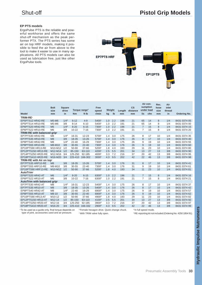
Hyd
raul
ic Im
puls
e N
utru
nner
s
Pneumatic Assembly Tools 3333
Shut-off Pistol Grip Models
a To be used as a guide only, fi nal torque depends on type of joint, accessories used and air pressure.
Air con- Rec. Air Bolt Square Free CS sumption hose inlet size drive Torque rangea speed Weight Length distance under load size thread Model mm in Nm ft lb r/min kg lb mm mm l/s cfm mm in Ordering No.TRIM-REe EP5PTS12 HR42-RE M5-M6 1/4b 6-12 4-9 5400c 1.0 2.2 196 21 65 14 8 1/4 8431 0374 05EP5PTS14 HR10-RE M5-M6 3/8 8-14 6-10 5400c 1.0 2.2 191 21 65 14 8 1/4 8431 0374 00EP6PTS20 HR42-RE M6 1/4b 8-20 6-15 7300c 1.0 2.2 196 21 7 15 8 1/4 8431 0374 15EP6PTS22 HR10-RE M6 3/8 10-22 7-16 7300c 1.0 2.2 191 21 7 15 8 1/4 8431 0374 20TRIM-RE with balanced gripe
EP7PTS30 HR42-RE M8 1/4b 16-31 12-23 5700c 1.4 3.0 175 26 8 17 10 1/4 8431 0374 35EP7PTS35 HR10-RE M8 3/8 18-35 13-26 5700c 1.4 3.0 176 26 8 17 10 1/4 8431 0374 40EP8PTS40 HR42-RE M8 1/4b 22-40 16-29 7300c 1.4 3.0 175 26 9 19 10 1/4 8431 0374 55EP8PTS55 HR10-RE M8-M10 3/8 30-55 22-40 7300c 1.4 3.0 176 26 9 19 10 1/4 8431 0374 60EP10PTS90 HR13-RE M10-M12 1/2 50-90 37-66 5200c 1.8 4.0 193 29 11 23 10 1/4 8431 0374 80EP12PTS150 HR13-RE M12-M14 1/2 85-150 63-110 4200c 2.5 5.5 201 34 13 27 13 3/8 8431 0374 90EP14PTS250 HR20-RE M12-M16 3/4 125-250 92-185 4000c 3.3 7.2 216 37 20 42 13 3/8 8431 0374 95EP18PTS410 HR20-RE M16-M20 3/4 225-410 166-302 3000c 4.3 9.5 202 42 22 46 13 3/8 8431 0374 98TRIM-RE with Air on tope
EP7PTS35 HRF10-RE M8 3/8 18-35 13-26 5700c 1.4 3.0 176 31 8 17 10 1/4 8431 0374 41EP8PTS55 HRF10-RE M8-M10 3/8 30-55 22-40 7300c 1.4 3.0 176 31 9 19 10 1/4 8431 0374 61EP10PTS90 HRF13-RE M10-M12 1/2 50-90 37-66 5200c 1.8 4.0 193 34 11 23 10 1/4 8431 0374 81AutoTrime
EP6PTS20 HR42-AT M6 1/4b 8-20 6-15 6300d 1.0 2.2 196 21 7 15 8 1/4 8431 0374 16EP6PTS22 HR10-AT M6 3/8 10-22 7-16 6300d 1.0 2.2 191 21 7 15 8 1/4 8431 0374 21AutoTrim with balanced gripe
EP7PTS30 HR42-AT M8 1/4b 16-31 12-23 5400d 1.4 3.0 175 26 8 17 10 1/4 8431 0374 37EP7PTS35 HR10-AT M8 3/8 18-35 13-26 5400d 1.4 3.0 176 26 8 17 10 1/4 8431 0374 42EP8PTS40 HR42-AT M8 1/4b 22-40 16-29 6900d 1.4 3.0 175 26 9 19 10 1/4 8431 0374 57EP8PTS55 HR10-AT M8-10 3/8 30-55 22-40 6900d 1.4 3.0 176 26 9 19 10 1/4 8431 0374 62EP10PTS90 HR13-AT M10-12 1/2 50-90 37-66 4900d 1.8 4.0 193 29 11 23 10 1/4 8431 0374 82EP12PTS150 HR13-AT M12-14 1/2 85-150 63-110 4100d 2.5 5.5 201 34 13 27 13 3/8 8431 0374 92EP14PTS250 HR20-AT M12-16 3/4 125-250 92-185 3900d 3.3 7.2 216 37 20 42 13 3/8 8431 0374 97EP18PTS410 HR20-AT M16-20 3/4 225-410 166-332 2900d 4.3 9.5 202 42 22 46 13 3/8 8431 0374 99
EP PTS modelsErgoPulse PTS is the reliable and pow-erful workhorse and offers the same shut-off mechanism as the peak per-former PTX. The PTS series has some air on top HRF models, making it pos-sible to feed the air from above to the tool to make it easier to use in many ap-plications. All PTS models can also be used as lubrication free, just like other ErgoPulse tools.
b Female hexagon drive. Quick change chuck.c With TRIM valve fully open.
d In full speed mode.e RE-reporting kit not included (Ordering No. 4250 1854 91).
Am_ErgoPulse.indd 33 2012-02-06 09:54:57

34 Pneumatic Assembly Tools
Hyd
raul
ic Im
puls
e N
utru
nner
s
34
Pistol Grip Models Non Shut-off
Air con- Rec. Air Bolt Square Free CS sumption hose inlet size drive Torque rangea speed Weight Length distance under load size thread Model mm in Nm ft lb r/min kg lb mm mm l/s cfm mm in Ordering No.EP5XS HR42 M5-M6 1/4b 5-12 4-9 8500 0.8 1.8 165 21 9 19 8 1/4 8431 0372 30EP6XS HR10 M6 3/8 10-20 7-15 8000 0.8 1.8 152 22 8 17 8 1/4 8431 0372 20EP6XS HR42 M6 1/4b 9-19 6-14 8000 0.8 1.8 150 22 8 17 8 1/4 8431 0372 23EP7XS HR10 M8 3/8 20-31 15-23 9000 0.8 1.8 152 22 8 17 8 1/4 8431 0372 00EP7XS HR42 M8 1/4b 17-28 13-21 9000 0.8 1.8 150 22 8 17 8 1/4 8431 0372 10EP10XS HR13 M10 1/2 50-70 37-52 6000 1.3 2.9 168 26 11 23 10 1/4 8431 0369 40EP12XS HR13 M12 1/2 65-110 48-81 4500 1.6 3.5 178 29 12 25 10 1/4 8431 0371 00EP14XS HR13 M14 1/2 110-160 81-118 3500 2.4 5.3 188 34 14 30 13 3/8 8431 0371 50EP16XS HR20 M16 3/4 160-240 118-177 2800 3.3 7.3 205 37 15 32 13 3/8 8431 0371 55EP20XS HR20 M20 3/4 300-400 221-295 3700 5.1 11.2 240 43 16 34 13 3/8 8431 0371 60EP8XS HRX10 M8-M10 3/8 30-52 22-38 7000 1.0 2.2 174 23 9 19 10 1/4 8431 0369 09EP8XS HRX42 M8 1/4b 22-40 16-29 7000 1.0 2.2 172 23 9 19 10 1/4 8431 0369 16EP6PS HR10 M8 3/8 c-30 c-22 8000 0.8 1.8 150 21 9 19 10 1/4 8431 0368 21EP6PS HR42 M8 1/4b c-28 c-21 8000 0.8 1.8 148 21 9 19 10 1/4 8431 0368 22EP8PS HR10 M8-M10 3/8 c-65 c-48 8000 1.0 2.2 158 23 9 19 10 1/4 8431 0368 24
EP XS modelsIn ErgoPulse non shut-off tools the tool produces pulses until the operator re-leases the trigger. Preferred in applica-tions where it is an advantage for the operator to be able to control the process by shutting off the tool manually.
l High reliability and durability.l High speed, short cycle times.l One-handed operation.l High power-to-weight ratio.l No springs to wear out.l High precision components.l No reaction forces.l Light, well-balanced tools. l Low noise levels.l Lubrication free.
a To be used as a guide only, fi nal torque depends on type of joint, accessories used and air pressure.
b Female hexagon drive. Quick change chuck.c Torque is adjusted by regulating the air pressure.
Am_ErgoPulse.indd 34 2012-02-06 09:54:58
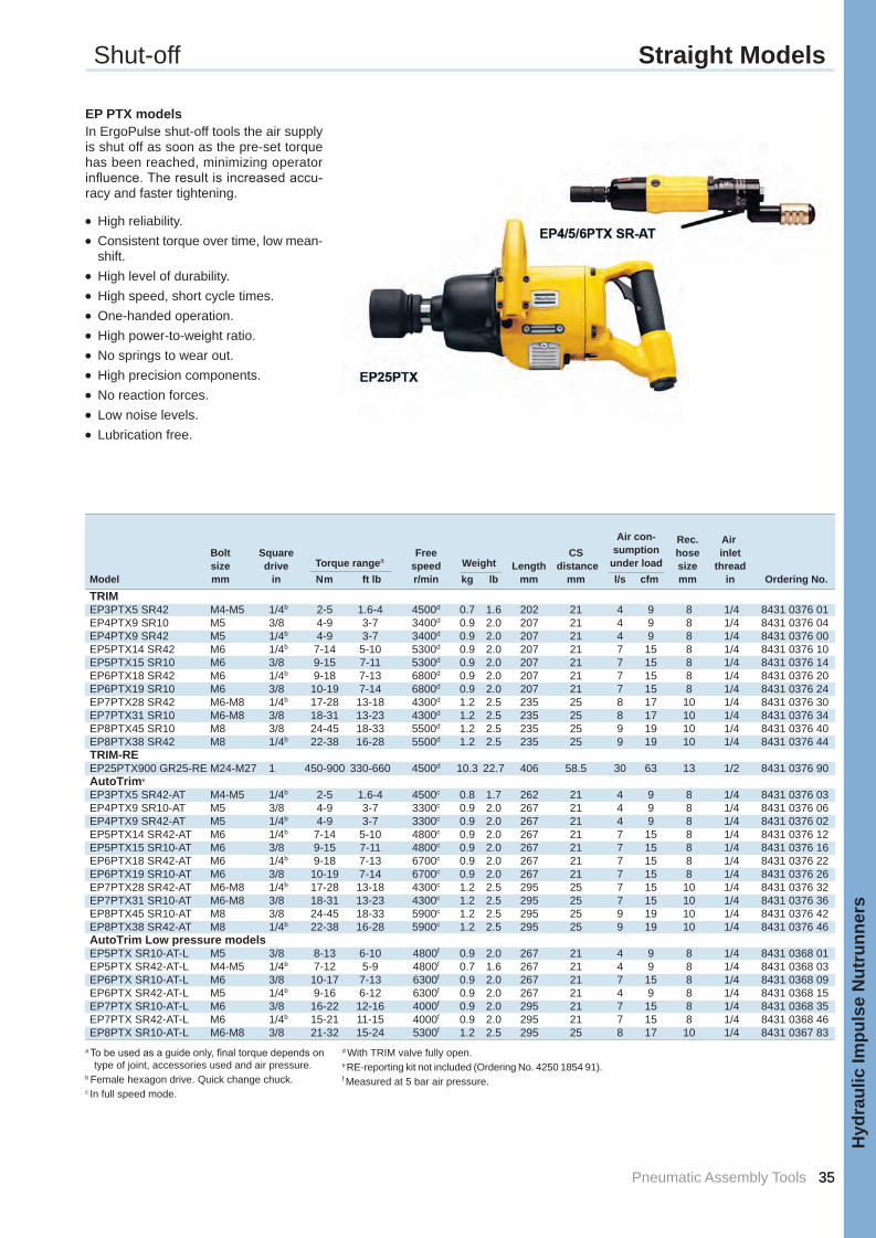
Hyd
raul
ic Im
puls
e N
utru
nner
s
Pneumatic Assembly Tools 3535
Shut-off Straight Models
Air con- Rec. Air Bolt Square Free CS sumption hose inlet size drive Torque rangea speed Weight Length distance under load size thread Model mm in Nm ft lb r/min kg lb mm mm l/s cfm mm in Ordering No.TRIM EP3PTX5 SR42 M4-M5 1/4b 2-5 1.6-4 4500d 0.7 1.6 202 21 4 9 8 1/4 8431 0376 01EP4PTX9 SR10 M5 3/8 4-9 3-7 3400d 0.9 2.0 207 21 4 9 8 1/4 8431 0376 04EP4PTX9 SR42 M5 1/4b 4-9 3-7 3400d 0.9 2.0 207 21 4 9 8 1/4 8431 0376 00EP5PTX14 SR42 M6 1/4b 7-14 5-10 5300d 0.9 2.0 207 21 7 15 8 1/4 8431 0376 10EP5PTX15 SR10 M6 3/8 9-15 7-11 5300d 0.9 2.0 207 21 7 15 8 1/4 8431 0376 14EP6PTX18 SR42 M6 1/4b 9-18 7-13 6800d 0.9 2.0 207 21 7 15 8 1/4 8431 0376 20EP6PTX19 SR10 M6 3/8 10-19 7-14 6800d 0.9 2.0 207 21 7 15 8 1/4 8431 0376 24EP7PTX28 SR42 M6-M8 1/4b 17-28 13-18 4300d 1.2 2.5 235 25 8 17 10 1/4 8431 0376 30EP7PTX31 SR10 M6-M8 3/8 18-31 13-23 4300d 1.2 2.5 235 25 8 17 10 1/4 8431 0376 34EP8PTX45 SR10 M8 3/8 24-45 18-33 5500d 1.2 2.5 235 25 9 19 10 1/4 8431 0376 40EP8PTX38 SR42 M8 1/4b 22-38 16-28 5500d 1.2 2.5 235 25 9 19 10 1/4 8431 0376 44TRIM-RE EP25PTX900 GR25-RE M24-M27 1 450-900 330-660 4500d 10.3 22.7 406 58.5 30 63 13 1/2 8431 0376 90AutoTrime EP3PTX5 SR42-AT M4-M5 1/4b 2-5 1.6-4 4500c 0.8 1.7 262 21 4 9 8 1/4 8431 0376 03EP4PTX9 SR10-AT M5 3/8 4-9 3-7 3300c 0.9 2.0 267 21 4 9 8 1/4 8431 0376 06EP4PTX9 SR42-AT M5 1/4b 4-9 3-7 3300c 0.9 2.0 267 21 4 9 8 1/4 8431 0376 02EP5PTX14 SR42-AT M6 1/4b 7-14 5-10 4800c 0.9 2.0 267 21 7 15 8 1/4 8431 0376 12EP5PTX15 SR10-AT M6 3/8 9-15 7-11 4800c 0.9 2.0 267 21 7 15 8 1/4 8431 0376 16EP6PTX18 SR42-AT M6 1/4b 9-18 7-13 6700c 0.9 2.0 267 21 7 15 8 1/4 8431 0376 22EP6PTX19 SR10-AT M6 3/8 10-19 7-14 6700c 0.9 2.0 267 21 7 15 8 1/4 8431 0376 26EP7PTX28 SR42-AT M6-M8 1/4b 17-28 13-18 4300c 1.2 2.5 295 25 7 15 10 1/4 8431 0376 32EP7PTX31 SR10-AT M6-M8 3/8 18-31 13-23 4300c 1.2 2.5 295 25 7 15 10 1/4 8431 0376 36EP8PTX45 SR10-AT M8 3/8 24-45 18-33 5900c 1.2 2.5 295 25 9 19 10 1/4 8431 0376 42EP8PTX38 SR42-AT M8 1/4b 22-38 16-28 5900c 1.2 2.5 295 25 9 19 10 1/4 8431 0376 46AutoTrim Low pressure models EP5PTX SR10-AT-L M5 3/8 8-13 6-10 4800f 0.9 2.0 267 21 4 9 8 1/4 8431 0368 01EP5PTX SR42-AT-L M4-M5 1/4b 7-12 5-9 4800f 0.7 1.6 267 21 4 9 8 1/4 8431 0368 03EP6PTX SR10-AT-L M6 3/8 10-17 7-13 6300f 0.9 2.0 267 21 7 15 8 1/4 8431 0368 09EP6PTX SR42-AT-L M5 1/4b 9-16 6-12 6300f 0.9 2.0 267 21 4 9 8 1/4 8431 0368 15EP7PTX SR10-AT-L M6 3/8 16-22 12-16 4000f 0.9 2.0 295 21 7 15 8 1/4 8431 0368 35EP7PTX SR42-AT-L M6 1/4b 15-21 11-15 4000f 0.9 2.0 295 21 7 15 8 1/4 8431 0368 46EP8PTX SR10-AT-L M6-M8 3/8 21-32 15-24 5300f 1.2 2.5 295 25 8 17 10 1/4 8431 0367 83
EP PTX models In ErgoPulse shut-off tools the air supply is shut off as soon as the pre-set torque has been reached, minimizing operator infl uence. The result is increased accu-racy and faster tightening.
l High reliability.l Consistent torque over time, low mean-
shift.l High level of durability.l High speed, short cycle times.l One-handed operation.l High power-to-weight ratio.l No springs to wear out.l High precision components.l No reaction forces.l Low noise levels.l Lubrication free.
a To be used as a guide only, fi nal torque depends on type of joint, accessories used and air pressure.
b Female hexagon drive. Quick change chuck.c In full speed mode.
d With TRIM valve fully open.e RE-reporting kit not included (Ordering No. 4250 1854 91).f Measured at 5 bar air pressure.
Am_ErgoPulse.indd 35 2012-02-06 09:54:59
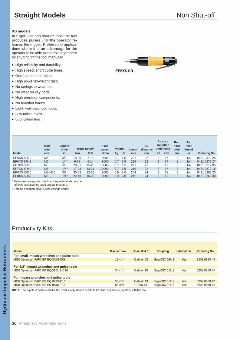
36 Pneumatic Assembly Tools
Hyd
raul
ic Im
puls
e N
utru
nner
s
36
Air con- Rec. Air Bolt Square Free CS sumption hose inlet size drive Torque rangea speed Weight Length distance under load size thread Model mm in Nm ft lb r/min kg lb mm mm l/s cfm mm in Ordering No.EP6XS SR10 M6 3/8 10-20 7-15 8000 0.7 1.5 221 22 8 17 8 1/4 8431 0372 25EP6XS SR42 M6 1/4b 9-19 6-14 8000 0.7 1.5 219 22 8 17 8 1/4 8431 0372 27EP7XS SR10 M8 3/8 20-31 15-23 10000 0.7 1.5 221 22 8 17 8 1/4 8431 0372 05EP7XS SR42 M8 1/4b 17-28 13-21 10000 0.7 1.5 219 22 8 17 8 1/4 8431 0372 15EP8XS SR10 M8-M10 3/8 30-52 22-38 8000 0.9 2.0 244 24 9 19 8 1/4 8431 0369 20EP8XS SR42 M8 1/4b 22-40 16-29 8000 0.9 2.0 242 24 9 19 8 1/4 8431 0369 30
XS models In ErgoPulse non shut-off tools the tool produces pulses until the operator re-leases the trigger. Preferred in applica-tions where it is an advantage for the operator to be able to control the process by shutting off the tool manually.
l High reliability and durability.l High speed, short cycle times.l One-handed operation.l High power-to-weight ratio.l No springs to wear out.l No wear on key parts.l High precision components.l No reaction forces.l Light, well-balanced tools. l Low noise levels.l Lubrication free.
Straight Models Non Shut-off
a To be used as a guide only, fi nal torque depends on type of joint, accessories used and air pressure.
b Female hexagon drive. Quick change chuck.
Model Max air fl ow Hose 16.4 ft Coupling Lubrication Ordering No.For small impact wrenches and pulse toolsMIDI Optimizer F/RD EP EQ08US-C08 19 cfm Cablair 08 ErgoQIC 08US Yes 8202 0850 45
For 1/2" impact wrenches and pulse tools MIDI Optimizer F/RD EP EQQ10US-C10 34 cfm Cablair 10 ErgoQIC 10US Yes 8202 0850 46
For impact wrenches and pulse toolsMIDI Optimizer F/RD EP EQ10US-C13 50 cfm Cablair 13 ErgoQIC 10US Yes 8202 0850 47MIDI Optimizer F/RD EP EQ10US-T13 65 cfm Turbo 13 ErgoQIC 10US Yes 8202 0850 48
Productivity Kits
NOTE: Tool nipple is not included in the Productivity kit and needs to be order separately together with the tool.
Am_ErgoPulse.indd 36 2012-02-06 09:54:59
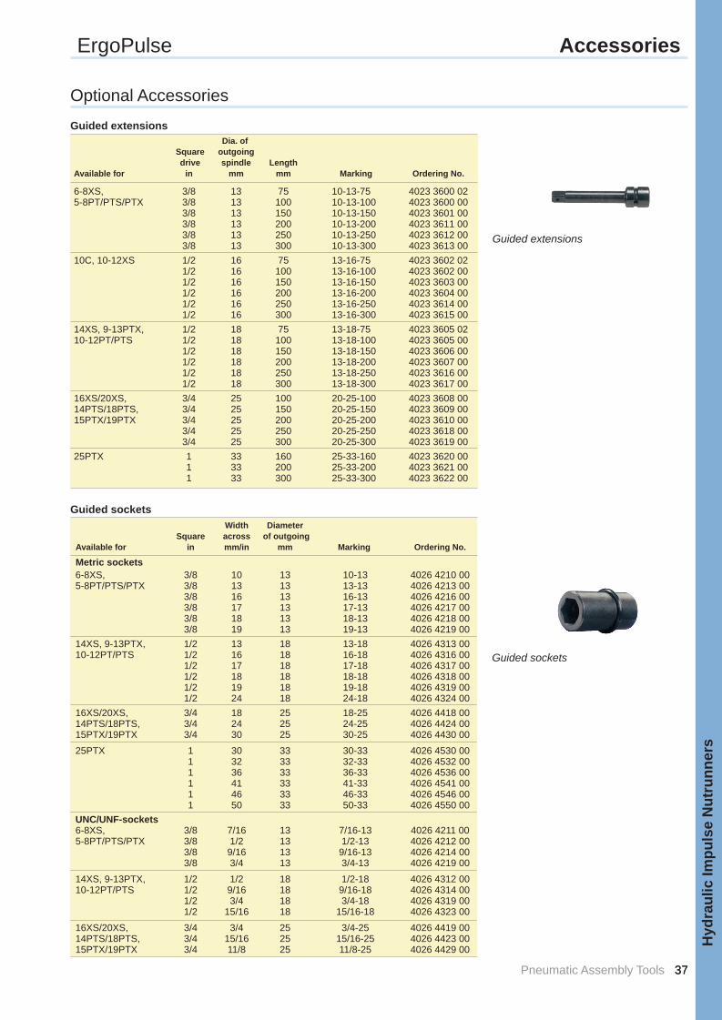
Hyd
raul
ic Im
puls
e N
utru
nner
s
Pneumatic Assembly Tools 3737
Dia. of Square outgoing drive spindle LengthAvailable for in mm mm Marking Ordering No.
6-8XS, 3/8 13 75 10-13-75 4023 3600 025-8PT/PTS/PTX 3/8 13 100 10-13-100 4023 3600 00 3/8 13 150 10-13-150 4023 3601 00 3/8 13 200 10-13-200 4023 3611 00 3/8 13 250 10-13-250 4023 3612 00 3/8 13 300 10-13-300 4023 3613 0010C, 10-12XS 1/2 16 75 13-16-75 4023 3602 02 1/2 16 100 13-16-100 4023 3602 00 1/2 16 150 13-16-150 4023 3603 00 1/2 16 200 13-16-200 4023 3604 00 1/2 16 250 13-16-250 4023 3614 00 1/2 16 300 13-16-300 4023 3615 0014XS, 9-13PTX, 1/2 18 75 13-18-75 4023 3605 0210-12PT/PTS 1/2 18 100 13-18-100 4023 3605 00 1/2 18 150 13-18-150 4023 3606 00 1/2 18 200 13-18-200 4023 3607 00 1/2 18 250 13-18-250 4023 3616 00 1/2 18 300 13-18-300 4023 3617 0016XS/20XS, 3/4 25 100 20-25-100 4023 3608 0014PTS/18PTS, 3/4 25 150 20-25-150 4023 3609 0015PTX/19PTX 3/4 25 200 20-25-200 4023 3610 00 3/4 25 250 20-25-250 4023 3618 00 3/4 25 300 20-25-300 4023 3619 0025PTX 1 33 160 25-33-160 4023 3620 00 1 33 200 25-33-200 4023 3621 00 1 33 300 25-33-300 4023 3622 00
Width Diameter Square across of outgoingAvailable for in mm/in mm Marking Ordering No.
Metric sockets6-8XS, 3/8 10 13 10-13 4026 4210 005-8PT/PTS/PTX 3/8 13 13 13-13 4026 4213 00 3/8 16 13 16-13 4026 4216 00 3/8 17 13 17-13 4026 4217 00 3/8 18 13 18-13 4026 4218 00 3/8 19 13 19-13 4026 4219 0014XS, 9-13PTX, 1/2 13 18 13-18 4026 4313 0010-12PT/PTS 1/2 16 18 16-18 4026 4316 00 1/2 17 18 17-18 4026 4317 00 1/2 18 18 18-18 4026 4318 00 1/2 19 18 19-18 4026 4319 00 1/2 24 18 24-18 4026 4324 0016XS/20XS, 3/4 18 25 18-25 4026 4418 0014PTS/18PTS, 3/4 24 25 24-25 4026 4424 0015PTX/19PTX 3/4 30 25 30-25 4026 4430 0025PTX 1 30 33 30-33 4026 4530 00 1 32 33 32-33 4026 4532 00 1 36 33 36-33 4026 4536 00 1 41 33 41-33 4026 4541 00 1 46 33 46-33 4026 4546 00 1 50 33 50-33 4026 4550 00UNC/UNF-sockets6-8XS, 3/8 7/16 13 7/16-13 4026 4211 005-8PT/PTS/PTX 3/8 1/2 13 1/2-13 4026 4212 00 3/8 9/16 13 9/16-13 4026 4214 00 3/8 3/4 13 3/4-13 4026 4219 0014XS, 9-13PTX, 1/2 1/2 18 1/2-18 4026 4312 0010-12PT/PTS 1/2 9/16 18 9/16-18 4026 4314 00 1/2 3/4 18 3/4-18 4026 4319 00 1/2 15/16 18 15/16-18 4026 4323 0016XS/20XS, 3/4 3/4 25 3/4-25 4026 4419 0014PTS/18PTS, 3/4 15/16 25 15/16-25 4026 4423 0015PTX/19PTX 3/4 11/8 25 11/8-25 4026 4429 00
Optional Accessories
Guided extensions
Guided sockets
ErgoPulse Accessories
Guided extensions
Guided sockets
Am_ErgoPulse.indd 37 2012-02-06 09:55:02

38 Pneumatic Assembly Tools
Hyd
raul
ic Im
puls
e N
utru
nner
s
38
Accessories ErgoPulse
Service Kits
Protective SupportPistol grip models cover handleEP6/7XS HR 4250 2089 00EP8XS HRX 4250 1895 00EP10XS HR 4250 1784 00EP12XS HR 4250 2459 00EP14XS HR 4250 2160 00EP16XS HR 4250 2282 00 4250 2396 91EP20XS HR 4250 2288 00 IncludedEP4/5/6PTX HR 4250 2465 00EP7/8PTX HR 4250 2466 00EP9PTX HR 4250 2467 00EP11PTX HR 4250 2551 00EP13PTX HR 4250 2718 00 4250 2396 81EP15PTX HR 4250 2674 00 4250 2396 83EP19PTX HR 4250 2719 00 4250 2396 82EP5/6PT/PTS HR 4250 2393 00EP7/8PT/PTS HR 4250 1784 00EP10PT/PTS HR 4250 1743 00EP12PT/PTS HR 4250 1858 00EP14PTS HR 4250 2228 00 4250 2396 81EP18PTS HR 4250 2319 00 4250 2396 80
For complete information, see spare parts list.
The spare parts included in the service kits cover a normal overhaul of your tool. Always have them available for a fast and economical repair.
Main parts included:l Vane kit l O-ringsl Motor bearings l Circlipsl Gaskets l Pins etc.
O-ring kit Model pulse unit Service kit
EP5XS 4210 2532 93 4081 0264 90EP6/7XS HR 4250 2084 90 4081 0188 90EP6/7XS SR 4250 2084 90 4081 0189 90EP6PS HR 4250 2058 91 4081 0274 90EP8PS HR 4250 2059 90 4081 0120 90EP8XS HR 4250 2085 90 4081 0119 90EP8XS SR 4250 2085 90 4081 0190 90EP10XS HR 4250 2086 90 4081 0191 90EP12XS HR 4250 2087 90 4081 0192 90EP14XS HR 4250 2170 90 4081 0200 90EP16XS HR 4250 2281 90 4081 0223 90EP20XS HR 4250 2281 91 4081 0245 90EP4PTX HR 4250 2058 90 4081 0122 90EP5/6PTX HR 4250 2058 90 4081 0122 90
O-ring kit Model pulse unit Service kit
EP7PTX HR 4250 2058 90 4081 0122 90EP8PTX HR 4250 2267 91 4081 0279 90EP9PTX HR 4250 2058 90 4081 0122 90EP11PTX HR 4250 2267 95 4081 0310 90EP13PTX HR 4250 2267 92 4081 0226 90EP15PTX HR 4250 2267 93 4081 0242 90EP19PTX HR 4250 2267 94 4081 0256 90EP25PTX GR 4250 2267 97 4081 0427 90EP5/6PTS HR 4250 2058 90 4081 0122 90EP7/8PTS HR 4250 2267 91 4081 0225 90EP10PTS HR 4250 2267 90 4081 0222 90EP12PTS HR 4250 2267 92 4081 0226 90EP14PTS HR 4250 2267 93 4081 0242 90EP18PTS HR 4250 2267 94 4081 0256 90
Oil filling kit (150 ml oil, syringe) 4081 0121 90 For complete information, see spare parts list.
Optional Accessories
Support handle
Protective cover
Diameter Square Female of outgoing drive hex spindleAvailable for in in mm Marking Ordering No.
6-8XS, 3/8 1/4 13 3/8-1/4-13 4026 4501 005-8PT/PTS/PTX 3/8 7/16 13 3/8-7/16-13 4026 4502 00
14XS, 9-13PTX, 1/2 7/16 18 1/2-7/16-18 4026 4503 0010-12PT/PTS
Guided quick change chuck for power tools
Guided quick change chuck
Am_ErgoPulse.indd 38 2012-02-06 09:55:08

Pneumatic Assembly Tools 39
Con
trol
led
Impu
lse
Nut
runn
ers
An impulse tool with fastening system intelligence
Introduction – Controlled Impulse Nutrunner
The Pulsor C, with its control system, is designed for quality critical applications. Pulsor C alerts you to mistakes as soon as they are made. Lights on the back of the tool indicate if screws are correctly tightened. They inform the user about torque, early shut-off or if parts have been forgotten. Pulsor C will control re-peatability and can report results.
The systemThe Pulsor C system comprises the tool, cable, controller and tool control box where the shut-off valve is located.
The toolPulsor C tools are an ergonomic, high-performance range of impulse nutrunners with signal lights to provide direct opera-tor feedback. No mechanical torque set-ting in tool.
CablesThe strong, resistant electric tool cable is available in three versions: straight, coil and spiral.
Tool Control BoxPressure adjustment and tool shut-off valves are located in this box.
ControllerThe controller remembers up to 4,000 tightenings – everything from torque re-sults and rundown time to identification number (see below for a full list of pa-rameters). The results can easily be sent to a network and stored on a server. They can also be transferred directly to a PC and then analyzed in a program such as Excel. This means that you can easily fine-tune your process.
Pulsor monitors and records: l Torque resultl Angle resultl Premature shut-offl Number of pulsesl Tightening timel Rundown timel Barcode number
SoftwareThe PC based ToolsTalk Pulsor C software is used for making all system settings.l Tool settingsl Communication settings to factory net-
works
Atlas Copco’s Pulsor C System gives you all the advantages of a controlled impulse tool, plus the intelligence of an electric fastening system. Like all Atlas Copco impulse tools, Pulsor C is fast, powerful, light and compact and generates virtually no reaction force. The controller remembers up to 4,000 tightenings that can be stored and ana-lyzed. This enables you to fine-tune your process and ensure that every tightening in every shift is perfect. If they are not perfect, you can see why.
Am_Pulsor.indd 39 2012-02-07 10:08:00
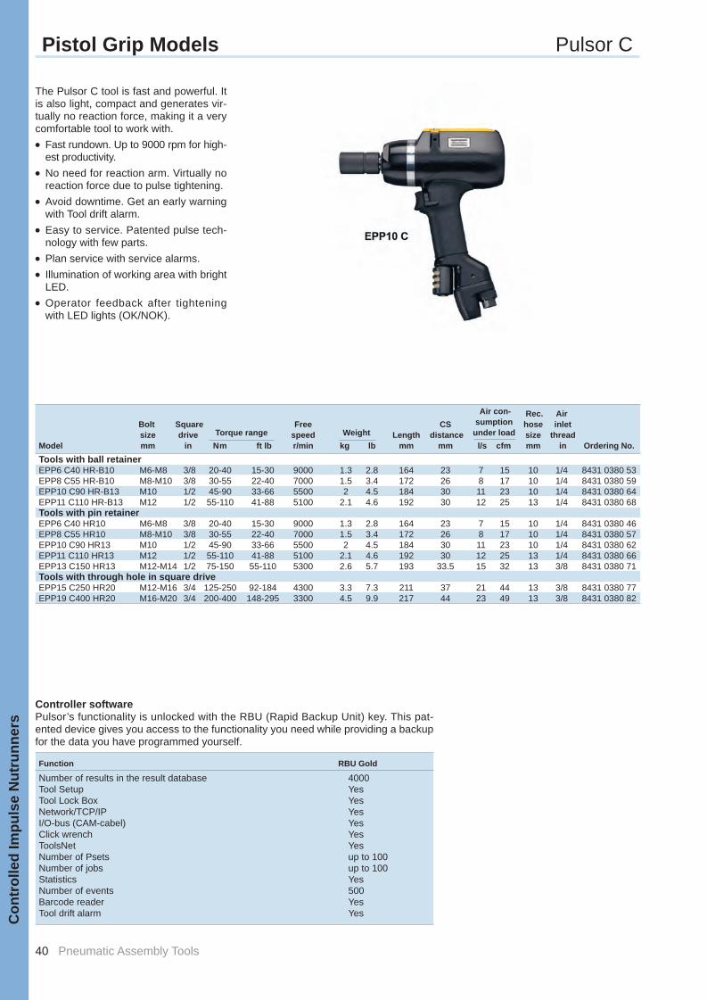
40 Pneumatic Assembly Tools
Con
trol
led
Impu
lse
Nut
runn
ers
Pistol Grip Models Pulsor C
The Pulsor C tool is fast and powerful. It is also light, compact and generates vir-tually no reaction force, making it a very comfortable tool to work with.l Fast rundown. Up to 9000 rpm for high-
est productivity.l No need for reaction arm. Virtually no
reaction force due to pulse tightening.l Avoid downtime. Get an early warning
with Tool drift alarm.l Easy to service. Patented pulse tech-
nology with few parts.l Plan service with service alarms.l Illumination of working area with bright
LED.l Operator feedback after tightening
with LED lights (OK/NOK).
Air con- Rec. Air Bolt Square Free CS sumption hose inlet size drive Torque range speed Weight Length distance under load size thread Model mm in Nm ft lb r/min kg lb mm mm l/s cfm mm in Ordering No.Tools with ball retainer EPP6 C40 HR-B10 M6-M8 3/8 20-40 15-30 9000 1.3 2.8 164 23 7 15 10 1/4 8431 0380 53EPP8 C55 HR-B10 M8-M10 3/8 30-55 22-40 7000 1.5 3.4 172 26 8 17 10 1/4 8431 0380 59EPP10 C90 HR-B13 M10 1/2 45-90 33-66 5500 2 4.5 184 30 11 23 10 1/4 8431 0380 64EPP11 C110 HR-B13 M12 1/2 55-110 41-88 5100 2.1 4.6 192 30 12 25 13 1/4 8431 0380 68Tools with pin retainer EPP6 C40 HR10 M6-M8 3/8 20-40 15-30 9000 1.3 2.8 164 23 7 15 10 1/4 8431 0380 46EPP8 C55 HR10 M8-M10 3/8 30-55 22-40 7000 1.5 3.4 172 26 8 17 10 1/4 8431 0380 57EPP10 C90 HR13 M10 1/2 45-90 33-66 5500 2 4.5 184 30 11 23 10 1/4 8431 0380 62EPP11 C110 HR13 M12 1/2 55-110 41-88 5100 2.1 4.6 192 30 12 25 13 1/4 8431 0380 66EPP13 C150 HR13 M12-M14 1/2 75-150 55-110 5300 2.6 5.7 193 33.5 15 32 13 3/8 8431 0380 71Tools with through hole in square drive EPP15 C250 HR20 M12-M16 3/4 125-250 92-184 4300 3.3 7.3 211 37 21 44 13 3/8 8431 0380 77EPP19 C400 HR20 M16-M20 3/4 200-400 148-295 3300 4.5 9.9 217 44 23 49 13 3/8 8431 0380 82
Controller softwarePulsor’s functionality is unlocked with the RBU (Rapid Backup Unit) key. This pat-ented device gives you access to the functionality you need while providing a backup for the data you have programmed yourself.
Function RBU Gold
Number of results in the result database 4000Tool Setup YesTool Lock Box YesNetwork/TCP/IP YesI/O-bus (CAM-cabel) YesClick wrench YesToolsNet YesNumber of Psets up to 100Number of jobs up to 100Statistics YesNumber of events 500Barcode reader YesTool drift alarm Yes
Am_Pulsor.indd 40 2012-02-07 10:08:01
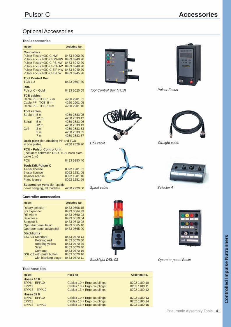
Pneumatic Assembly Tools 41
Con
trol
led
Impu
lse
Nut
runn
ers
Pulsor C Accessories
Model Ordering No.
ControllersPulsor Focus 4000-C-HW 8433 6900 20Pulsor Focus 4000-C-DN-HW 8433 6940 20Pulsor Focus 4000-C-PB-HW 8433 6942 20Pulsor Focus 4000-C-PN-HW 8433 6948 20Pulsor Focus 4000-C-EIP-HW 8433 6949 20Pulsor Focus 4000-C-IB-HW 8433 6945 20Tool Control BoxTCB-1U 8433 0607 30RBUPulsor C - Gold 8433 6020 05TCB cablesCable PF - TCB, 1.2 m 4250 2901 01Cable PF - TCB, 5 m 4250 2901 05Cable PF - TCB, 10 m 4250 2901 10Tool cablesStraight 5 m 4250 2533 05 12 m 4250 2533 12Spiral 5 m 4250 2533 06 12 m 4250 2533 13Coil 3 m 4250 2533 53 5 m 4250 2533 55 7 m 4250 2533 57Back plate (for attaching PF and TCB in one plate) 4250 2829 90PCU - Pulsor Control Unit(Includes: controller, RBU, TCB, back plate, cable 1 m)PCU 8433 6980 40ToolsTalk Pulsor C1-user license 8092 1281 015-user license 8092 1281 0510-user license 8092 1281 10Plant license 8092 1281 99Suspension yoke (for upsidedown hanging, all models) 4250 2720 00
Optional AccessoriesTool accessories
Controller accessoriesModel Ordering No.
Rotary selector 8433 0606 15I/O Expander 8433 0564 39RE-Alarm 8433 0560 03Selector 4 8433 0610 04Selector 8 8433 0610 08Operator panel basic 8433 0565 10Operator panel advanced 8433 0565 00StacklightsESL-04 Standard 8433 0570 13 Rotating red 8433 0570 30 Rotating yellow 8433 0570 35 Siren 8433 0570 40 Compact 8433 0570 16DSL-03 with push button 8433 0570 10 with blanking plugs 8433 0570 11
Pulsor Focus
Straight cable
Spiral cable
Coil cable
Tool Control Box (TCB)
Tool hose kitsModel Hose kit Ordering No.Hoses 16 ftEPP6 – EPP10 Cablair 10 + Ergo couplings 8202 1180 10EPP11 Cablair 13 + Ergo couplings 8202 1180 11EPP13 – EPP19 Cablair 13 + Ergo couplings 8202 1180 12Hoses 32 ftEPP6 – EPP10 Cablair 10 + Ergo couplings 8202 1180 13EPP11 Cablair 13 + Ergo couplings 8202 1180 14EPP13 – EPP19 Cablair 13 + Ergo couplings 8202 1180 15
Selector 4
Operator panel BasicStacklight DSL-03
Am_Pulsor.indd 41 2012-02-07 10:08:19
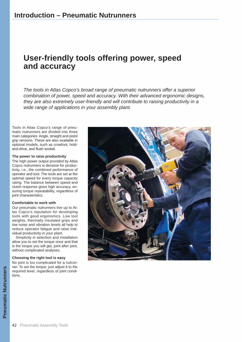
Pneu
mat
ic N
utru
nner
s
42 Pneumatic Assembly Tools
The tools in Atlas Copco’s broad range of pneumatic nutrunners offer a superior combination of power, speed and accuracy. With their advanced ergonomic designs, they are also extremely user-friendly and will contribute to raising productivity in a wide range of applications in your assembly plant.
Introduction – Pneumatic Nutrunners
Tools in Atlas Copco’s range of pneu-matic nutrunners are divided into three main categories: Angle, straight and pistol grip versions. These are also available in optional models, such as crowfoot, hold-and-drive, and flush socket.
The power to raise productivity The high power output provided by Atlas Copco nutrunners is decisive for produc-tivity, i.e., the combined performance of operator and tool. The tools are set at the optimal speed for every torque capacity rating. The balance between speed and clutch response gives high accuracy, en-suring torque repeatability, regardless of joint characteristics.
Comfortable to work withOur pneumatic nutrunners live up to At-las Copco’s reputation for developing tools with good ergonomics. Low tool weights, thermally insulated grips and low noise and vibration levels all help to reduce operator fatigue and raise indi-vidual productivity in your plant.
Simplicity in selection and installation allow you to set the torque once and that is the torque you will get, joint after joint, without complicated analyses.
Choosing the right tool is easyNo joint is too complicated for a nutrun-ner. To set the torque, just adjust it to the required level, regardless of joint condi-tions.
User-friendly tools offering power, speed and accuracy
Am_Nutrunners.indd 42 2012-02-06 10:50:41
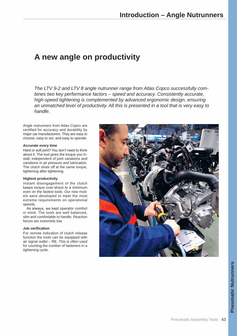
Pneu
mat
ic N
utru
nner
s
Pneumatic Assembly Tools 43
The LTV 9-2 and LTV 8 angle nutrunner range from Atlas Copco successfully com-bines two key performance factors – speed and accuracy. Consistently accurate, high-speed tightening is complemented by advanced ergonomic design, ensuring an unmatched level of productivity. All this is presented in a tool that is very easy to handle.
Angle nutrunners from Atlas Copco are certified for accuracy and durability by major car manufacturers. They are easy to choose, easy to set, and easy to operate.
Accurate every time Hard or soft joint? You don’t need to think about it. The tool gives the torque you in-stall, independent of joint variations and variations in air pressure and lubrication. The clutch shuts off at the same torque, tightening after tightening.
Highest productivity Instant disengagement of the clutch keeps torque over-shoot to a minimum even on the fastest tools. Our new mod-els were developed to meet the most extreme requirements on operational speeds.
As always, we kept operator comfort in mind. The tools are well balanced, slim and comfortable to handle. Reaction forces are extremely low.
Job verification For remote indication of clutch release function the tools can be equipped with air signal outlet – RE. This is often used for counting the number of fasteners in a tightening cycle.
Introduction – Angle Nutrunners
A new angle on productivity
Am_Nutrunners.indd 43 2012-02-06 10:50:48
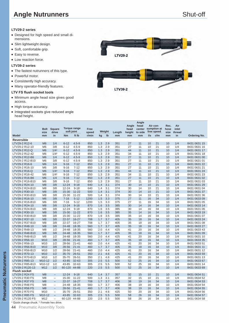
Pneu
mat
ic N
utru
nner
s
44 Pneumatic Assembly Tools
LTV29-2 seriesl Designed for high speed and small di-
mensions. l Slim lightweight design.l Soft, comfortable grip. l Easy to reverse.l Low reaction force.
LTV39-2 seriesl The fastest nutrunners of this type. l Powerful motor.l Consistently high accuracy. l Many operator-friendly features.
LTV FS fl ush socket toolsl Minimum angle head size gives good
access. l High torque accuracy. l Integrated sockets give reduced angle
head height.
Angle Angle head Air con- Rec. Air Bolt Square Torque range Free head center sumption at hose inlet size drive soft joint speed Weight Length height to side free speed size thread Model mm in Nm ft lb r/min kg lb mm mm mm l/s cfm mm in Ordering No.ReversibleLTV29-2 R12-6 M6 1/4 6-12 4.5-9 850 1.3 2.9 351 27 11 10 21 10 1/4 8431 0631 15LTV29-2 R12-10 M6 3/8 6-12 4.5-9 850 1.3 2.9 351 27 11 10 21 10 1/4 8431 0631 16LTV29-2 R12-Q M6 1/4a 6-12 4.5-9 850 1.3 2.9 351 44 11 10 21 10 1/4 8431 0631 17LTV29-2 R12-42 M6 1/4b 6-12 4.5-9 850 1.3 2.9 351 34 11 10 21 10 1/4 8431 0631 18LTV29-2 R12-B6 M6 1/4 6-12 4.5-9 850 1.3 2.9 351 27 11 10 21 10 1/4 8431 0631 00LTV29-2 R12-B10 M6 3/8 6-12 4.5-9 850 1.3 2.9 351 27 11 10 21 10 1/4 8431 0631 01LTV29-2 R16-6 M6 1/4 9-16 7-12 850 1.3 2.9 351 27 11 10 21 10 1/4 8431 0631 22LTV29-2 R16-10 M6 3/8 9-16 7-12 850 1.3 2.9 351 27 11 10 21 10 1/4 8431 0631 21LTV29-2 R16-Q M6 1/4a 9-16 7-12 850 1.3 2.9 351 44 11 10 21 10 1/4 8431 0631 24LTV29-2 R16-42 M6 1/4b 9-16 7-12 850 1.3 2.9 351 34 11 10 21 10 1/4 8431 0631 23LTV29-2 R16-B6 M6 1/4 9-16 7-12 850 1.3 2.9 351 27 11 10 21 10 1/4 8431 0631 02LTV29-2 R16-B10 M6 3/8 9-16 7-12 850 1.3 2.9 351 27 11 10 21 10 1/4 8431 0631 03LTV29-2 R24-10 M8 3/8 12-24 9-18 640 1.4 3.1 374 30 14 10 21 10 1/4 8431 0631 29LTV29-2 R24-B10 M8 3/8 12-24 9-18 640 1.4 3.1 374 30 14 10 21 10 1/4 8431 0631 04LTV29-2 R30-10 M8 3/8 15-30 11-22 500 1.4 3.1 374 30 14 10 21 10 1/4 8431 0631 37LTV29-2 R30-B10 M8 3/8 15-30 11-22 500 1.4 3.1 374 30 14 10 21 10 1/4 8431 0631 36LTV39-2 R16-10 M6 3/8 7-16 5-12 1200 1.5 3.3 375 27 11 16 34 10 1/4 8431 0633 09LTV39-2 R16-B10 M6 3/8 7-16 5-12 1200 1.5 3.3 375 27 11 16 34 10 1/4 8431 0631 05LTV39-2 R24-10 M8 3/8 12-24 9-18 870 1.6 3.5 385 30 14 16 34 10 1/4 8431 0633 14LTV39-2 R24-B10 M8 3/8 12-24 9-18 870 1.6 3.5 385 30 14 16 34 10 1/4 8431 0631 06LTV39-2 R30-10 M8 3/8 15-30 11-22 870 1.6 3.5 385 35 14 16 34 10 1/4 8431 0633 19LTV39-2 R30-B10 M8 3/8 15-30 11-22 870 1.6 3.5 385 35 14 16 34 10 1/4 8431 0631 07LTV39-2 R37-10 M8 3/8 22-37 16-27 708 1.7 3.7 405 35 18 16 34 10 1/4 8431 0633 24LTV39-2 R37-B10 M8 3/8 22-37 16-27 708 1.7 3.7 405 35 18 16 34 10 1/4 8431 0631 08LTV39-2 R48-10 M8 3/8 24-48 18-35 560 1.7 3.7 405 35 18 16 34 10 1/4 8431 0633 27LTV39-2 R48-13 M8 1/2 24-48 18-35 560 2.0 4.4 425 41 20 16 34 10 1/4 8431 0633 43LTV39-2 R48-B10 M8 3/8 24-48 18-35 560 1.7 3.7 405 35 18 16 34 10 1/4 8431 0631 09LTV39-2 R48-B13 M8 1/2 24-48 18-35 560 2.0 4.4 425 41 20 16 34 10 1/4 8431 0631 10LTV39-2 R56-10 M10 3/8 28-56 21-41 460 1.7 3.7 405 35 18 16 34 10 1/4 8431 0633 35LTV39-2 R56-13 M10 1/2 28-56 21-41 460 2.0 4.4 425 41 20 16 34 10 1/4 8431 0633 51LTV39-2 R56-B10 M10 3/8 28-56 21-41 460 1.7 3.7 405 35 18 16 34 10 1/4 8431 0631 11LTV39-2 R56-B13 M10 1/2 28-56 21-41 460 2.0 4.4 425 41 20 16 34 10 1/4 8431 0631 12LTV39-2 R70-13 M10 1/2 35-70 26-51 350 2.1 4.6 425 41 20 16 34 10 1/4 8431 0633 59LTV39-2 R70-B13 M10 1/2 35-70 26-51 350 2.1 4.6 425 41 20 16 34 10 1/4 8431 0631 13LTV39-2 R85-13 M10-12 1/2 43-85 32-63 305 2.5 5.5 500 52 25 16 34 10 1/4 8431 0633 67LTV39-2 R85-B13 M10-12 1/2 43-85 32-63 305 2.5 5.5 500 52 25 16 34 10 1/4 8431 0631 14LTV39-2 R120-13 M12 1/2 60-120 44-88 220 2.5 5.5 500 52 25 16 34 10 1/4 8431 0633 69Flush socketLTV29-2 R24 FS M8 – 12-24 9-18 640 1.4 3.7 357 32 15 10 21 10 1/4 8431 0634 51LTV29-2 R30 FS M8 – 15-30 11-22 500 1.3 3.1 357 32 15 10 21 10 1/4 8431 0634 52LTV39-2 R37 FS M8 – 22-37 16-27 708 1.7 3.7 406 38 19 16 34 10 1/4 8431 0634 53LTV39-2 R48 FS M8 – 24-48 18-35 560 1.7 3.7 406 38 19 16 34 10 1/4 8431 0634 54LTV39-2 R56 FS M8 – 28-56 21-41 460 1.7 3.7 406 38 19 16 34 10 1/4 8431 0634 55LTV39-2 R70 FS M10 – 35-70 26-51 350 2.1 4.6 425 50 20 16 34 10 1/4 8431 0634 56LTV39-2 R85 FS M10-12 – 43-85 32-63 305 2.5 5.5 500 58 26 16 34 10 1/4 8431 0634 57LTV39-2 R120 FS M12 – 60-120 44-88 220 2.5 5.5 500 58 26 16 34 10 1/4 8431 0634 58
a Quick change chuck. b Female hex drive.
Angle Nutrunners Shut-off
Am_Nutrunners.indd 44 2012-02-06 10:50:49
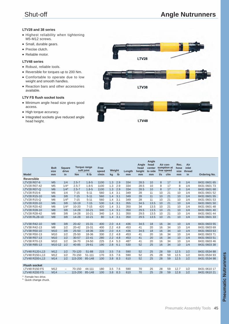
Pneu
mat
ic N
utru
nner
s
Pneumatic Assembly Tools 45
LTV28 and 38 seriesl Highest reliability when tightening
M5-M12 screws.l Small, durable gears.l Precise clutch. l Reliable motor.
LTV48 seriesl Robust, reliable tools.l Reversible for torques up to 200 Nm.l Comfortable to operate due to low
weight and smooth handles. l Reaction bars and other accessories
available.
LTV FS fl ush socket toolsl Minimum angle head size gives good
access. l High torque accuracy. l Integrated sockets give reduced angle
head height.
Angle Angle head Air con- Rec. Air Bolt Square Torque range Free head center sumption at hose inlet size drive soft joint speed Weight Length height to side free speed size thread Model mm in Nm ft lb r/min kg lb mm mm mm l/s cfm mm in Ordering No.ReversibleLTV28 R07-6 M5 1/4 2.5-7 1.8-5 1100 1.3 2.9 334 28.5 10 8 17 8 1/4 8431 0601 65LTV28 R07-42 M5 1/4a 2.5-7 1.8-5 1100 1.3 2.9 334 28.5 10 8 17 8 1/4 8431 0601 73LTV28 R07-Q M6 1/4b 2.5-7 1.8-5 1100 1.3 2.9 334 28.5 10 8 17 8 1/4 8431 0601 68LTV28 R15-6 M6 1/4 7-15 5-11 560 1.4 3.1 349 28 11 10 21 10 1/4 8431 0601 52LTV28 R15-10 M6 3/8 7-15 5-11 560 1.4 3.1 349 28 11 10 21 10 1/4 8431 0601 55LTV28 R15-Q M6 1/4b 7-15 5-11 560 1.4 3.1 349 28 11 10 21 10 1/4 8431 0601 53LTV28 R20-10 M6 3/8 10-19 7-15 530 1.4 3.1 355 34.5 13.5 10 21 10 1/4 8431 0601 50LTV28 R20-42 M6 1/4a 10-20 7-15 420 1.4 3.1 350 34 13.5 10 21 10 1/4 8431 0601 48LTV28 R28-10 M8 3/8 14-28 10-21 340 1.4 3.1 350 29.5 13.5 10 21 10 1/4 8431 0601 40LTV28 R28-42 M8 3/8 14-28 10-21 340 1.4 3.1 350 29.5 13.5 10 21 10 1/4 8431 0601 44LTV28 RL28-10 M8 3/8 14-28 10-21 80 1.4 3.1 350 29.5 13.5 10 21 10 1/4 8431 0601 33 LTV38 R42-10 M8 3/8 20-42 15-31 400 2.0 4.4 436 34.5 18 16 34 10 1/4 8431 0603 55LTV38 R42-13 M8 1/2 20-42 15-31 400 2.2 4.8 453 41 20 16 34 10 1/4 8431 0603 69LTV38 R50-10 M10 3/8 25-50 18-36 330 2.0 4.4 436 34.5 18 16 34 10 1/4 8431 0603 63LTV38 R50-13 M10 1/2 25-50 18-36 330 2.2 4.8 453 41 20 16 34 10 1/4 8431 0603 71LTV38 R57-13 M10 1/2 30-57 22-41 280 2.2 4.8 453 41 20 16 34 10 1/4 8431 0603 51LTV38 R70-13 M10 1/2 34-70 24-50 225 2.4 5.3 487 41 20 16 34 10 1/4 8431 0603 46LTV38 R85-13 M10-12 1/2 40-85 29-61 190 2.8 6.1 530 52 25 16 34 10 1/4 8431 0603 38
LTV48 R120-L13 M12 1/2 70-120 51-88 215 3.5 7.6 590 52 25 28 59 12.5 1/2 8431 0534 88LTV48 R150-L13 M12 1/2 70-150 51-111 170 3.5 7.6 590 52 25 28 59 12.5 1/2 8431 0534 93LTV48 R200-L13 M14 1/2 115-200 85-148 100 3.8 8.3 610 52 25 28 59 12.5 1/2 8431 0534 98
Flush socketLTV48 R150 FS M12 – 70-150 44-111 180 3.5 7.6 590 70 25 28 59 12.7 1/2 8431 0610 17LTV48 R200 FS M14 – 115-200 85-148 100 3.8 8.3 610 70 25 28 59 12.8 1/2 8431 0610 21
a Female hex drive.b Quick change chuck.
Shut-off Angle Nutrunners
Am_Nutrunners.indd 45 2012-02-06 10:50:50
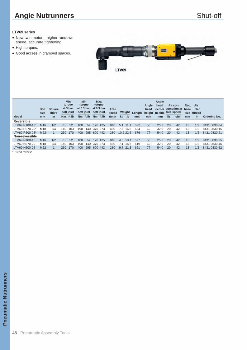
Pneu
mat
ic N
utru
nner
s
46 Pneumatic Assembly Tools
Min Min Max Angle torque torque torque Angle head Air con- Rec. Air Bolt Square at 3 bar at 6.3 bar at 6.3 bar Free head center sumption at hose inlet size drive soft joint soft joint soft joint speed Weight Length height to side free speed size thread Model mm in Nm ft lb Nm ft lb Nm ft lb r/min kg lb mm mm mm l/s cfm mm in Ordering No.ReversibleLTV69 R180-13a M16 1/2 70 52 100 74 170 125 840 5.1 11.1 592 50 25.3 20 42 13 1/2 8431 0830 04LTV69 R370-20a M18 3/4 140 103 190 140 370 273 480 7.6 16.6 634 62 32.9 20 42 13 1/2 8431 0830 15LTV69 R600-25a M22 1 230 170 400 295 600 443 280 10.2 22.6 676 77 54.0 20 42 13 1/2 8431 0830 21Non-reversibleLTV69 N180-13 M16 1/2 70 52 100 74 170 125 840 4.6 10.1 577 50 25.3 20 42 13 1/2 8431 0830 35LTV69 N370-20 M18 3/4 140 103 190 140 370 273 480 7.1 15.6 619 62 32.9 20 42 13 1/2 8431 0830 46LTV69 N600-25 M22 1 230 170 400 295 600 443 280 9.7 21.3 661 77 54.0 20 42 13 1/2 8431 0830 52
LTV69 seriesl New twin motor – higher rundown
speed, accurate tightening.l High torques.l Good access in cramped spaces.
Angle Nutrunners Shut-off
a Fixed reverse.
Am_Nutrunners.indd 46 2012-02-06 10:50:50
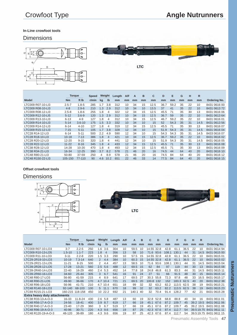
Pneu
mat
ic N
utru
nner
s
Pneumatic Assembly Tools 47
Torque Speed Weight Length A/F A B C D E F G H R Model Nm ft lb r/min kg lb mm mm mm mm mm mm mm mm mm mm mm Ordering No.LTC009 R07-10-LO3 3-7 2.2-5 250 1.6 3.6 304 10 59.5 10 14.55 32.8 42.8 61.1 36.5 22 10 8431 0614 94LTC009 R10-13-LO5 1.5-10 1.1-7 223 1.8 4 356 13 58 10 71.6 93.6 108.1 130.1 44 31 14.5 8431 0615 00LTC009 R11-10-LO3 3-11 2.2-8 220 1.5 3.3 290 10 57.5 15 14.55 32.8 42.8 61.1 36.5 22 10 8431 0615 01LTC29-2R19-10-LO3 10-19 7.3-14 640 2 4.4 384 10 60.3 15 14.55 32.8 42.8 61.1 36.5 22 10 8431 0615 02LTC29-2R21-13-LO5 11-21 8-15 500 2 4.4 457 13 58.5 10 71.6 93.6 108.1 130.1 44 31 14.5 8431 0615 04LTC39-2R28-12-LO5 17-28 13-21 560 2.5 5.6 488 12 69.5 15 62 84 97 119 44 30 13 8431 0615 08LTC39-2R40-14-LO3 22-40 16-29 460 2.4 5.3 452 14 77.8 18 24.8 46.8 61.3 83.3 44 31 14.5 8431 0615 11LTC39-2R60-16-LO3 34-60 25-44 305 3 6.7 541 16 91 24 27 51 66 91.5 48 30 15 8431 0615 14LTC48 R80-17-LO3 56-80 41-59 215 4 8.9 641 17 69.5 27 30.3 55.8 72.3 97.8 48 33 16.5 8431 0615 17LTC48 R90-21-LO5 49-90 36-66 170 4.7 10.4 721 21 69.5 20 100.8 132 152 183.3 62.5 40 20 8431 0612 38LTC48 R96-18-LO3 56-96 41-71 210 4.7 10.4 651 18 99 32 32 63.2 82.2 113.5 62.5 38 19 8431 0615 21LTC48 R140-18-LO3 92-140 68-103 100 5 11.1 670 18 99 32 32 63.2 82.2 113.5 62.5 38 19 8431 0615 23LTC69 R215-21-LO3 160-215 118-158 450 10 22.2 692 21 140.1 40 32 70.4 91.4 128.2 77 42 21 8431 0615 28Extra heavy duty attachmentsLTC38 R33-13-A-O-3 16-33 11.8-24 430 2.6 5.8 487 13 60 19 32.8 52.8 68.8 88.8 40 34 16 8431 0611 01LTC48 R56-17-A-O-3 24-56 18-41 400 3.9 8.7 619 17 66 19 45.1 67.6 87.2 109.7 45 39.2 19.5 8431 0611 06LTC38 R40-17-A-O-3 23-40 17-29 360 3 6.7 519 17 66 19 45.1 67.6 87.2 109.7 45 39.2 19.5 8431 0611 08LTC48 R96-19-A-O-3 40-96 30-71 220 4.3 9.6 656 19 87 25 42.3 67.6 87.4 112.7 54 39.5 19.75 8431 0611 11LTC48 R120-19-A-O-3 48-120 36-89 180 4.3 9.6 656 19 87 25 42.3 67.6 87.4 112.7 54 39.5 19.75 8431 0611 15
Torque Speed Weight Length A/F A B C D E G H R Model Nm ft lb r/min kg lb mm mm mm mm mm mm mm mm mm mm Ordering No.LTC009 R07-10-LI3 2.5-7 1.8-5 285 1.7 3.8 312 10 34 15 12.5 36.7 59.2 35 22 10 8431 0616 00LTC009 R08-10-LI3 4-8 2.9-6 210 1.3 2.9 312 10 34 10 13.5 37 41 35 22 10 8431 0613 72LTC009 R08-12-LI3 2.5-8 1.8-6 255 1.8 4 322 12 34 15 12.5 45.5 71 35 30 13 8431 0616 06LTC009 R12-10-LI5 5-12 3.6-9 120 1.3 2.9 312 10 34 15 12.5 36.7 59 35 22 10 8431 0613 64LTC009 R13-10-LI3 6-13 4-9 127 1.8 4 312 10 34 15 12.5 46.7 59.2 35 22 10 8431 0616 01LTC009 R14-10-LI3 5-14 3.6-10 175 1.5 3.3 332 10 34 10 15 52 54.3 35 31 14.5 8431 0613 56LTC009 R14-12-LI3 6-14 4-10 127 1.8 4 319 12 34 15 12.5 45.5 71 35 30 13 8431 0616 07LTC009 R15-12-LI3 7-15 5-11 105 1.7 3.8 328 12 34 10 15 51.9 54.3 35 31 14.5 8431 0616 04LTC28 R14-12-LI3 6-14 5-11 500 2.2 4.9 590 12 34 10 15 54.3 54.3 35 31 14.5 8433 0616 07LTC28 R18-10-LI3 10-18 7-13 386 1.8 4 421 10 34 15 12.5 36.7 59.2 35 22 10 8431 0616 02LTC28 R20-12-LI3 12-20 9-15 320 1.8 4 441 12 34 10 15 51.9 54.3 35 31 14.5 8431 0616 05LTC28 R22-12-LI3 11-22 8-16 345 1.8 4 433 12 34 15 12.5 45.5 71 35 30 13 8431 0616 08LTC38 R28-12-LI3 14-28 10-20 470 1.8 4 493 12 34 15 12.5 45.5 71 35 30 13 8431 0616 09LTC38 R34-21-LI3 16-34 12-25 390 3.7 8.2 578 21 46 20 16 74.5 44 64 40 20 8431 0616 10LTC48 R80-21-LI3 50-80 37-59 250 4 8.9 578 21 46 20 16 74.5 84 64 40 20 8431 0616 12LTC48 R150-22-LI3 105-150 77-110 90 4.6 10.2 651 22 46 33 14 77.5 84 64 40 20 8431 0616 15
Offset crowfoot tools
Dimensions
In-Line crowfoot tools
Dimensions
Crowfoot Type Angle Nutrunners
Am_Nutrunners.indd 47 2012-02-06 10:50:52
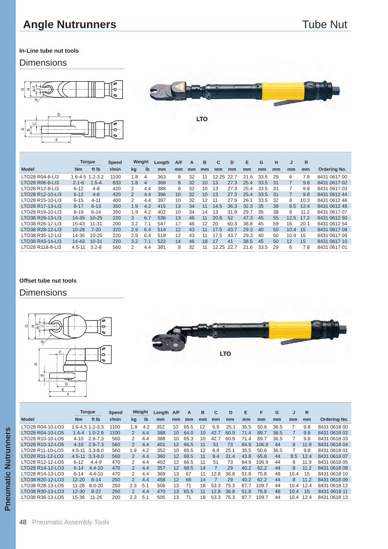
Pneu
mat
ic N
utru
nner
s
48 Pneumatic Assembly Tools
Angle Nutrunners Tube Nut
In-Line tube nut tools
Dimensions
Torque Speed Weight Length A/F A B C D E G H J R Model Nm ft lb r/min kg lb mm mm mm mm mm mm mm mm mm mm mm Ordering No.LTO28 R04-8-LI3 1.6-4.5 1.2-3.2 1100 1.8 4 363 8 32 11 12.25 22.7 21.6 33.5 29 6 7.8 8431 0617 00LTO28 R06-8-LI3 2.1-6 1.5-4 833 1.8 4 369 8 32 10 13 27.3 25.4 33.5 31 7 9.8 8431 0617 02LTO28 R12-8-LI3 6-12 4-8 420 2 4.4 388 8 32 10 13 27.3 25.4 33.5 31 7 9.8 8431 0617 03LTO28 R12-10-LI3 6-12 4-8 420 2 4.4 396 10 32 10 13 27.3 25.4 33.5 31 7 9.8 8431 0612 44LTO28 R15-10-LI3 6-15 4-11 400 2 4.4 397 10 32 12 11 27.9 26.1 33.5 32 8 10.3 8431 0612 46LTO28 R17-13-LI3 8-17 6-13 350 1.9 4.2 415 13 34 11 14.5 36.3 32.3 35 38 8.5 12.4 8431 0612 48LTO28 R19-10-LI3 8-19 6-14 350 1.9 4.2 402 10 34 14 13 31.9 29.7 35 38 8 11.2 8431 0617 07LTO38 R26-13-LI3 14-35 10-25 220 3 6.7 536 13 46 11 20.8 52 47.3 45 55 12.5 17.2 8431 0612 50LTO38 R26-17-LI3 15-43 11-31 200 3.2 7.1 547 17 46 12 20 60.3 38.8 45 59 16 20.1 8431 0612 54LTO38 R28-12-LI3 10-28 7-20 320 2.9 6.4 514 12 43 11 17.5 43.7 29.3 40 50 10.4 15 8431 0617 08LTO38 R35-12-LI3 14-35 10-25 220 2.9 6.4 519 12 43 11 17.5 43.7 29.3 40 50 10.4 15 8431 0617 09LTO38 R43-14-LI3 14-43 10-31 220 3.2 7.1 522 14 46 18 17 41 38.5 45 50 12 15 8431 0617 10LTO28 R118-8-LI3 4.5-11 3.2-8 560 2 4.4 381 8 32 11 12.25 22.7 21.6 33.5 29 6 7.8 8431 0617 01
Offset tube nut tools
Dimensions
Torque Speed Weight Length A/F A B C D E F G J R Model Nm ft lb r/min kg lb mm mm mm mm mm mm mm mm mm mm mm Ordering No.LTO28 R04-10-LO3 1.6-4.5 1.2-3.3 1100 1.9 4.2 352 10 65.5 12 6.9 25.1 35.5 50.6 36.5 7 9.8 8431 0618 00LTO28 R04-10-LO5 1.4-4 1.0-2.9 1100 2 4.4 388 10 64.0 10 42.7 60.9 71.4 89.7 36.5 7 9.8 8431 0618 02LTO28 R10-10-LO5 4-10 2.9-7.3 560 2 4.4 388 10 65.3 10 42.7 60.9 71.4 89.7 36.5 7 9.8 8431 0618 03LTO28 R10-12-LO5 4-10 2.9-7.3 560 2 4.4 401 12 66.5 11 51 73 84.9 106.9 44 8 11.9 8431 0618 04LTO28 R11-10-LO3 4.5-11 3.3-8.0 560 1.9 4.2 352 10 65.5 12 6.9 25.1 35.5 50.6 36.5 7 9.8 8431 0618 01LTO28 R11-12-LO3 4.5-11 3.3-8.0 560 2 4.4 360 12 68.5 11 9.4 31.4 43.8 65.8 44 8.5 12.4 8431 0618 07LTO28 R12-12-LO5 6-12 4.4-9 470 2 4.4 402 12 66.5 11 51 73 84.9 106.9 44 8 11.9 8431 0618 05LTO28 R14-12-LO3 6-14 4.4-10 470 2 4.4 357 12 68.5 14 7 29 40.2 62.2 44 8 11.2 8431 0618 08LTO28 R14-13-LO3 6-14 4.4-10 470 2 4.4 369 13 67 11 12.8 36.8 51.8 75.8 48 10.4 15 8431 0618 10LTO38 R20-12-LO3 12-20 8-14 250 2 4.4 458 12 68 14 7 29 40.2 62.2 44 8 11.2 8431 0618 09LTO38 R28-13-LO5 11-28 8.0-20 250 2.3 5.1 506 13 71 18 53.3 75.3 87.7 109.7 44 10.4 12.4 8431 0618 12LTO38 R30-13-LO3 12-30 8-22 250 2 4.4 470 13 65.5 11 12.8 36.8 51.8 75.8 48 10.4 15 8431 0618 11LTO38 R36-13-LO5 15-36 11-26 200 2.3 5.1 505 13 71 18 53.3 75.3 87.7 109.7 44 10.4 12.4 8431 0618 13
Am_Nutrunners.indd 48 2012-02-06 10:50:53
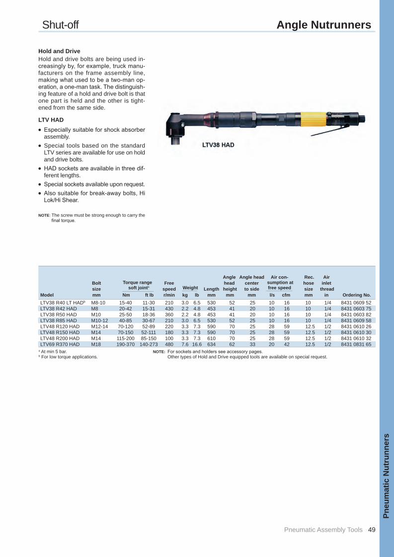
Pneu
mat
ic N
utru
nner
s
Pneumatic Assembly Tools 49
Shut-off Angle Nutrunners
Hold and DriveHold and drive bolts are being used in-creasingly by, for example, truck manu-facturers on the frame assembly line, making what used to be a two-man op-eration, a one-man task. The distinguish-ing feature of a hold and drive bolt is that one part is held and the other is tight-ened from the same side.
LTV HADl Especially suitable for shock absorber
assembly.l Special tools based on the standard
LTV series are available for use on hold and drive bolts.
l HAD sockets are available in three dif-ferent lengths.
l Special sockets available upon request.l Also suitable for break-away bolts, Hi
Lok/Hi Shear.
NOTE: The screw must be strong enough to carry the final torque.
Angle Angle head Air con- Rec. Air Bolt Torque range Free head center sumption at hose inlet size soft jointa speed Weight Length height to side free speed size thread Model mm Nm ft lb r/min kg lb mm mm mm l/s cfm mm in Ordering No.LTV38 R40 LT HADb M8-10 15-40 11-30 210 3.0 6.5 530 52 25 10 16 10 1/4 8431 0609 52LTV38 R42 HAD M8 20-42 15-31 430 2.2 4.8 453 41 20 10 16 10 1/4 8431 0603 75LTV38 R50 HAD M10 25-50 18-36 360 2.2 4.8 453 41 20 10 16 10 1/4 8431 0603 82LTV38 R85 HAD M10-12 40-85 30-67 210 3.0 6.5 530 52 25 10 16 10 1/4 8431 0609 58LTV48 R120 HAD M12-14 70-120 52-89 220 3.3 7.3 590 70 25 28 59 12.5 1/2 8431 0610 26LTV48 R150 HAD M14 70-150 52-111 180 3.3 7.3 590 70 25 28 59 12.5 1/2 8431 0610 30LTV48 R200 HAD M14 115-200 85-150 100 3.3 7.3 610 70 25 28 59 12.5 1/2 8431 0610 32LTV69 R370 HAD M18 190-370 140-273 480 7.6 16.6 634 62 33 20 42 12.5 1/2 8431 0831 65
a At min 5 bar.b For low torque applications.
NOTE: For sockets and holders see accessory pages. Other types of Hold and Drive equipped tools are available on special request.
Am_Nutrunners.indd 49 2012-02-06 10:50:54
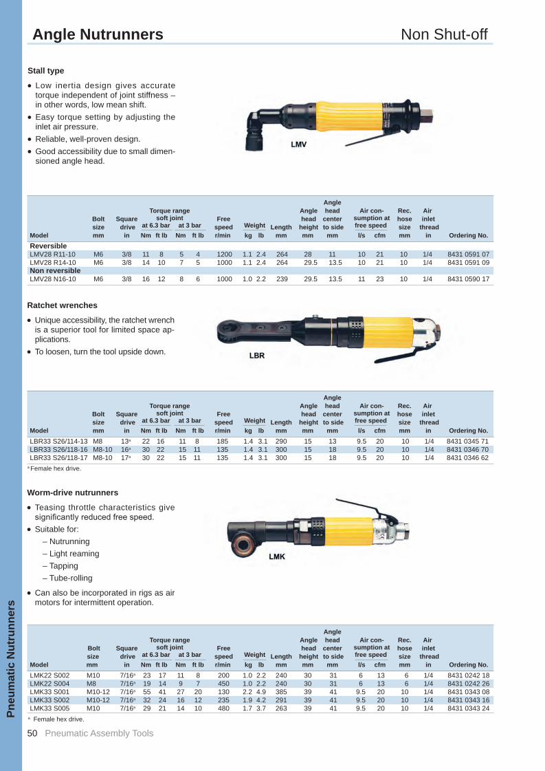
Pneu
mat
ic N
utru
nner
s
50 Pneumatic Assembly Tools
Stall typel Low inertia design gives accurate
torque independent of joint stiffness – in other words, low mean shift.
l Easy torque setting by adjusting the inlet air pressure.
l Reliable, well-proven design.l Good accessibility due to small dimen-
sioned angle head.
Angle Torque range Angle head Air con- Rec. Air Bolt Square soft joint Free head center sumption at hose inlet size drive at 6.3 bar at 3 bar speed Weight Length height to side free speed size thread Model mm in Nm ft lb Nm ft lb r/min kg lb mm mm mm l/s cfm mm in Ordering No.ReversibleLMV28 R11-10 M6 3/8 11 8 5 4 1200 1.1 2.4 264 28 11 10 21 10 1/4 8431 0591 07LMV28 R14-10 M6 3/8 14 10 7 5 1000 1.1 2.4 264 29.5 13.5 10 21 10 1/4 8431 0591 09Non reversible LMV28 N16-10 M6 3/8 16 12 8 6 1000 1.0 2.2 239 29.5 13.5 11 23 10 1/4 8431 0590 17
Angle Torque range Angle head Air con- Rec. Air Bolt Square soft joint Free head center sumption at hose inlet size drive at 6.3 bar at 3 bar speed Weight Length height to side free speed size thread Model mm in Nm ft lb Nm ft lb r/min kg lb mm mm mm l/s cfm mm in Ordering No.LBR33 S26/114-13 M8 13a 22 16 11 8 185 1.4 3.1 290 15 13 9.5 20 10 1/4 8431 0345 71LBR33 S26/118-16 M8-10 16a 30 22 15 11 135 1.4 3.1 300 15 18 9.5 20 10 1/4 8431 0346 70LBR33 S26/118-17 M8-10 17a 30 22 15 11 135 1.4 3.1 300 15 18 9.5 20 10 1/4 8431 0346 62
Angle Torque range Angle head Air con- Rec. Air Bolt Square soft joint Free head center sumption at hose inlet size drive at 6.3 bar at 3 bar speed Weight Length height to side free speed size thread Model mm in Nm ft lb Nm ft lb r/min kg lb mm mm mm l/s cfm mm in Ordering No.LMK22 S002 M10 7/16a 23 17 11 8 200 1.0 2.2 240 30 31 6 13 6 1/4 8431 0242 18LMK22 S004 M8 7/16a 19 14 9 7 450 1.0 2.2 240 30 31 6 13 6 1/4 8431 0242 26LMK33 S001 M10-12 7/16a 55 41 27 20 130 2.2 4.9 385 39 41 9.5 20 10 1/4 8431 0343 08LMK33 S002 M10-12 7/16a 32 24 16 12 235 1.9 4.2 291 39 41 9.5 20 10 1/4 8431 0343 16LMK33 S005 M10 7/16a 29 21 14 10 480 1.7 3.7 263 39 41 9.5 20 10 1/4 8431 0343 24
Ratchet wrenchesl Unique accessibility, the ratchet wrench
is a superior tool for limited space ap-plications.
l To loosen, turn the tool upside down.
Worm-drive nutrunnersl Teasing throttle characteristics give
signifi cantly reduced free speed.l Suitable for:
– Nutrunning– Light reaming– Tapping – Tube-rolling
l Can also be incorporated in rigs as air motors for intermittent operation.
a Female hex drive.
a Female hex drive.
Angle Nutrunners Non Shut-off
Am_Nutrunners.indd 50 2012-02-06 10:50:55

Pneu
mat
ic N
utru
nner
s
Pneumatic Assembly Tools 51
L
Suspension yoke Protective cover Reaction Signal connectionModel Exhaust hose Fixed Swivelling (see picture) bar kit kit (-RE)
LTV28 R07 4210 2053 00 4210 1631 82 4210 3931 80 4210 3990 00a 4210 4019 90LTV28, all models except R07 4210 2053 00 4210 1631 82 4210 3931 80 4210 3990 00a 4210 4018 90LTV29-2/39-2 4210 2053 00 4210 1631 82 4210 4408 80 4210 4017 90LTV29-2/39-2 R12/R16 4220 2744 05b LTV29-2/39-2 R24/R30 4220 2744 03b LTV38 R42/R50/R57 4210 2053 00 4210 1631 82 4210 3931 81 4210 3992 90a (not LTC) 4210 4017 90LTC38, LTV38 FS LTV38 R70 4210 2053 00 4210 1631 82 4210 3931 81 4210 4003 90a 4210 4017 90LTV38 R85, LTV38 HAD 4210 2053 00 4210 1631 82 4210 3931 81 4210 4004 90a 4210 4020 80 4210 4017 90LTV39-2 R48-10/R50-10 4220 2744 02b LTV39-2 R48-13/R50-13/R70 4220 2744 04b LTV48 R65 4210 4011 00 4210 4061 80 4210 4021 80 4210 4058 90a 4210 4020 80 4210 4057 90LTV48 R120/R150/R200, LTC48, 4210 4011 00 4210 4061 80 4210 4021 80 4210 4059 90a 4210 4020 80 4210 4057 90LTV48 FS, LTV48 HAD LTV69 N/R180 4210 4011 00 4210 3088 87 4210 4059 90a 4220 1128 80 LTV69 N/R370 4210 4011 00 4210 3088 87 4220 1201 80 LTV69 N/R600 4210 4011 00 4210 3088 87 4220 1746 80
Protective cover (b)Protective cover (a)Reaction bar kit Signal connection kit (RE)
Angle Nutrunners Accessories
Accessories Included
Optional Accessories
For LTV and LTC models
For LTV models Clutch adjustment key
For LBR, LMV and LMK modelsSocket adapter, 3/8" square drive LMK22, 1/2" square drive LMK33
Extensions for LTV Length of extension –"L" Suitablefor tool mm in Ordering No.
LTV28 75 3 4210 3491 93LTV28 150 6 4210 3491 95LTV38 (not R70/R85) 75 3 4210 4301 80LTV38 (not R70/R85) 150 6 4210 4302 80LTV38 R70/R85/LTV48 75 3 4210 4303 80LTV38 R70/R85/LTV48 150 6 4210 4304 80LTV39-2 R48-10 75 3 4210 4472 81LTV39-2 R48-10 150 6 4210 4472 83LTV39-2 R48/56/70-13 75 3 4210 4472 80LTV39-2 R48/56/70-13 150 6 4210 4473 80LTV39-2 R56-10 75 3 4210 4472 82LTV39-2 R56-10 150 6 4210 4472 84LTV39-2 R85 75 3 4210 4474 80LTV39-2 R85 150 6 4210 4475 80
Am_Nutrunners.indd 51 2012-02-06 10:51:04
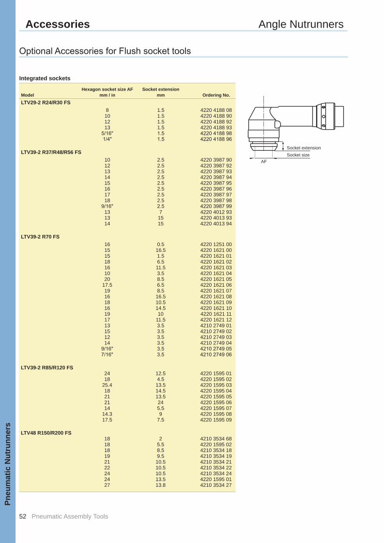
Pneu
mat
ic N
utru
nner
s
52 Pneumatic Assembly Tools
Integrated sockets
Socket extension
Socket size
Optional Accessories for Flush socket tools
Accessories Angle Nutrunners
Hexagon socket size AF Socket extension Model mm / in mm Ordering No.LTV29-2 R24/R30 FS 8 1.5 4220 4188 08 10 1.5 4220 4188 90 12 1.5 4220 4188 92 13 1.5 4220 4188 93 5/16" 1.5 4220 4188 98 1/4" 1.5 4220 4188 96
LTV39-2 R37/R48/R56 FS 10 2.5 4220 3987 90 12 2.5 4220 3987 92 13 2.5 4220 3987 93 14 2.5 4220 3987 94 15 2.5 4220 3987 95 16 2.5 4220 3987 96 17 2.5 4220 3987 97 18 2.5 4220 3987 98 9/16" 2.5 4220 3987 99 13 7 4220 4012 93 13 15 4220 4013 93 14 15 4220 4013 94
LTV39-2 R70 FS 16 0.5 4220 1251 00 15 16.5 4220 1621 00 15 1.5 4220 1621 01 18 6.5 4220 1621 02 16 11.5 4220 1621 03 10 3.5 4220 1621 04 20 8.5 4220 1621 05 17.5 6.5 4220 1621 06 19 8.5 4220 1621 07 16 16.5 4220 1621 08 18 10.5 4220 1621 09 16 14.5 4220 1621 10 19 10 4220 1621 11 17 11.5 4220 1621 12 13 3.5 4210 2749 01 15 3.5 4210 2749 02 12 3.5 4210 2749 03 14 3.5 4210 2749 04 9/16" 3.5 4210 2749 05 7/16" 3.5 4210 2749 06
LTV39-2 R85/R120 FS 24 12.5 4220 1595 01 18 4.5 4220 1595 02 25.4 13.5 4220 1595 03 18 14.5 4220 1595 04 21 13.5 4220 1595 05 21 24 4220 1595 06 14 5.5 4220 1595 07 14.3 9 4220 1595 08 17.5 7.5 4220 1595 09
LTV48 R150/R200 FS 18 2 4210 3534 68 18 5.5 4220 1595 02 18 8.5 4210 3534 18 19 9.5 4210 3534 19 21 10.5 4210 3534 21 22 10.5 4210 3534 22 24 10.5 4210 3534 24 24 13.5 4220 1595 01 27 13.8 4210 3534 27
AF
Am_Nutrunners.indd 52 2012-02-06 10:51:05
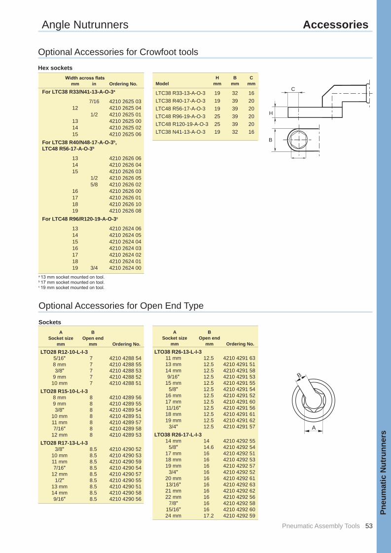
Pneu
mat
ic N
utru
nner
s
Pneumatic Assembly Tools 53
A
B
H
C
B
Sockets A B Socket size Open end mm mm Ordering No.
LTO28 R12-10-L-I-3 5/16" 7 4210 4288 54 8 mm 7 4210 4288 55 3/8" 7 4210 4288 53 9 mm 7 4210 4288 52 10 mm 7 4210 4288 51LTO28 R15-10-L-I-3
8 mm 8 4210 4289 56 9 mm 8 4210 4289 55 3/8" 8 4210 4289 54 10 mm 8 4210 4289 51 11 mm 8 4210 4289 57 7/16" 8 4210 4289 58 12 mm 8 4210 4289 53LTO28 R17-13-L-I-3
3/8" 8.5 4210 4290 52 10 mm 8.5 4210 4290 53 11 mm 8.5 4210 4290 59 7/16" 8.5 4210 4290 54 12 mm 8.5 4210 4290 57 1/2" 8.5 4210 4290 55 13 mm 8.5 4210 4290 51 14 mm 8.5 4210 4290 58 9/16" 8.5 4210 4290 56
A B Socket size Open end mm mm Ordering No.
LTO38 R26-13-L-I-3 11 mm 12.5 4210 4291 63 13 mm 12.5 4210 4291 51 14 mm 12.5 4210 4291 58 9/16" 12.5 4210 4291 53 15 mm 12.5 4210 4291 55 5/8" 12.5 4210 4291 54 16 mm 12.5 4210 4291 52 17 mm 12.5 4210 4291 60 11/16" 12.5 4210 4291 56 18 mm 12.5 4210 4291 61 19 mm 12.5 4210 4291 62 3/4" 12.5 4210 4291 57LTO38 R26-17-L-I-3
14 mm 14 4210 4292 55 5/8" 14.6 4210 4292 54 17 mm 16 4210 4292 51 18 mm 16 4210 4292 53 19 mm 16 4210 4292 57 3/4" 16 4210 4292 52 20 mm 16 4210 4292 61 13/16" 16 4210 4292 63 21 mm 16 4210 4292 62 22 mm 16 4210 4292 56 7/8" 16 4210 4292 58 15/16" 16 4210 4292 60 24 mm 17.2 4210 4292 59
Width across flats mm in Ordering No.
For LTC38 R33/N41-13-A-O-3a
7/16 4210 2625 03 12 4210 2625 04 1/2 4210 2625 01 13 4210 2625 00 14 4210 2625 02 15 4210 2625 06
For LTC38 R40/N48-17-A-O-3b, LTC48 R56-17-A-O-3b
13 4210 2626 06 14 4210 2626 04 15 4210 2626 03 1/2 4210 2626 05 5/8 4210 2626 02 16 4210 2626 00 17 4210 2626 01 18 4210 2626 10 19 4210 2626 08
For LTC48 R96/R120-19-A-O-3c
13 4210 2624 06 14 4210 2624 05 15 4210 2624 04 16 4210 2624 03 17 4210 2624 02 18 4210 2624 01 19 3/4 4210 2624 00a 13 mm socket mounted on tool.b 17 mm socket mounted on tool.c 19 mm socket mounted on tool.
Optional Accessories for Crowfoot toolsHex sockets
H B CModel mm mm mm
LTC38 R33-13-A-O-3 19 32 16LTC38 R40-17-A-O-3 19 39 20LTC48 R56-17-A-O-3 19 39 20LTC48 R96-19-A-O-3 25 39 20LTC48 R120-19-A-O-3 25 39 20LTC38 N41-13-A-O-3 19 32 16
Optional Accessories for Open End Type
Angle Nutrunners Accessories
Am_Nutrunners.indd 53 2012-02-06 10:51:05
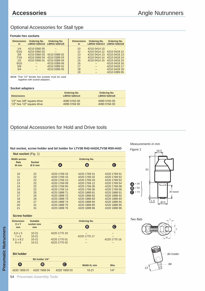
Pneu
mat
ic N
utru
nner
s
54 Pneumatic Assembly Tools
A
CB
A B C
18.5
61
Ø D 1.5
= 34
= 54
= 74
Y
X
W
A B C
A B C
Screw holder Dimension Suitable Ordering No. X x Y socket size mm mm
6.6 x 5 10-21 4220 1770 19 – – 7 x 5 10-21 – 4220 1770 17 – 5.1 x 8.2 10-21 4220 1770 01 – 4220 1770 16 8 x 6 10-21 4220 1770 02 – –
Nut socket (Fig. 1) Width across Ordering No. flats Socket W mm Ø D mm
10 22 4220 1769 16 4220 1769 31 4220 1769 51 11 22 4220 1769 15 4220 1769 32 4220 1769 52 12 22 4220 1769 13 4220 1769 33 4220 1769 53 13 22 4220 1769 09 4220 1769 12 4220 1769 54 14 22 4220 1769 05 4220 1769 35 4220 1769 08 15 22 4220 1769 14 4220 1769 36 4220 1769 56 16 25 4220 1888 71 4220 1888 81 4220 1888 91 17 25 4220 1888 72 4220 1888 82 4220 1888 92 18 26 4220 1888 73 4220 1888 83 4220 1888 93 19 27 4220 1888 74 4220 1888 84 4220 1888 94 20 31 4220 1888 75 4220 1888 85 4220 1888 95 21 31 4220 1888 76 4220 1888 86 4220 1888 96
Ordering No. Ordering No.Dimensions LBR33 S26/114 LBR33 S26/118
1/2" hex 3/8" square drive 4090 0163 00 4090 0163 001/2" hex 1/2" square drive 4090 0164 00 4090 0164 00
Dimensions Ordering No. Ordering No. in LBR33 S26/114 LBR33 S26/118
1/4 4210 0360 05 – 5/16 4210 0360 02 – 3/8 4210 0360 03 4210 0389 02 7/16 4210 0360 04 4210 0389 03 1/2 4210 0360 01 4210 0389 04 9/16 – 4210 0389 06 5/8 – 4210 0389 01 3/4 – 4210 0389 05
Dimensions Ordering No. Ordering No. in LBR33 S26/114 LBR33 S26/118
10 4210 0414 10 – 12 4210 0414 12 4210 0418 12 13 4210 0414 13 4210 0418 13 14 4210 0414 14 4210 0418 14 15 4210 0414 15 4210 0418 15 16 – 4210 0418 16 17 – 4210 0418 17 18 – 4210 0418 18 19 – 4210 0389 05
Female hex sockets
NOTE: That 1/2" female hex sockets must be used together with socket adapters.
Optional Accessories for Stall type
Measurements in mm
Figure 1
30 travel
Two flats
Bit holder Bit holder 1/4"
Width N, mm Bits
4220 1959 01 4220 1959 04 4220 1959 03 10-21 1/4"
Nut socket, screw holder and bit holder for LTV38 R42-HAD/LTV38 R50-HAD
Bit holder
Bit13
Accessories Angle Nutrunners
Optional Accessories for Hold and Drive tools
Socket adapters
Am_Nutrunners.indd 54 2012-02-06 10:51:06

Pneu
mat
ic N
utru
nner
s
Pneumatic Assembly Tools 55
N
W
N
W
B C
A B
B C
A B C
A
CB
26
76
5 Ø D
= 33
= 53
= 73
Y
X
W
A
C
A
Bit holder – Female hexagon
Bit holder 5/16" 5/16" Bits
Width N, mm Ordering No.4210 2991 91 4210 2991 92 4210 2991 93 5 4023 1215 00 6 4023 1216 00 7 4023 1219 00 8 4023 1217 00 10 4023 1218 00
Screw holder – Male hexagon
Suitable Ordering No. Dimension socket size N mm mm
7 14-24 4210 2825 41 4210 2825 42 4210 2825 43 8 14-24 4210 2825 01 4210 2825 05 4210 2825 09 9 15-24 4210 2825 02 4210 2825 06 4210 2825 10 10 18-24 4210 2825 03 4210 2825 07 4210 2825 11 11 19-24 4210 2825 04 4210 2825 08 4210 2825 12 12 19-24 4210 2825 13 4210 2825 14 4210 2825 15
Screw holder – Two flats
Dimension Suitable Ordering No. X x Y socket size mm mm
8 x 6.3 15-24 4210 2694 17 4210 2694 18 4210 2694 19 8 x 6 15-24 4210 2694 05 4210 2694 10 4210 2694 15 9.55 x 7.6 18-24 4210 2694 01 4210 2694 06 4210 2694 11 11.20 x 8.9 19-24 4210 2694 02 4210 2694 07 4210 2694 12 13 x 9.8 19-24 4210 2694 03 4210 2694 08 4210 2694 13 13.20 x 10.5 19-24 4210 2694 04 4210 2694 09 4210 2694 14
Nut socket (Fig. 2) Width across Ordering No. flats Socket W mm Ø D mm
13 30 4210 3513 13 4210 3513 33 4210 3513 53 14 30 4210 3513 14 4210 3513 34 4210 3513 54 15 30 4210 3513 15 4210 3513 35 4210 3513 55 16 30 4210 3513 16 4210 3513 36 4210 3513 56 17 30 4210 3513 17 4210 3513 37 4210 3513 57 18 31 4210 3513 18 4210 3513 38 4210 3513 58 19 32 4210 3513 19 4210 3513 39 4210 3513 59 21 35 4210 3513 21 4210 3513 41 4210 3513 61 22 35 4210 3513 22 4210 3513 42 4210 3513 62 24 35 4210 3513 24 4210 3513 44 4210 3513 64
Male hexagon
Female hexagon
Optional Accessories for Hold and Drive tools
Figure 2
30 travel
Nut socket, screw holder and bit holder for LTV38 R40 LT/R 85 HAD and LTV48 HADMeasurements in mm
Angle Nutrunners Accessories
Two flats
Am_Nutrunners.indd 55 2012-02-06 10:51:07
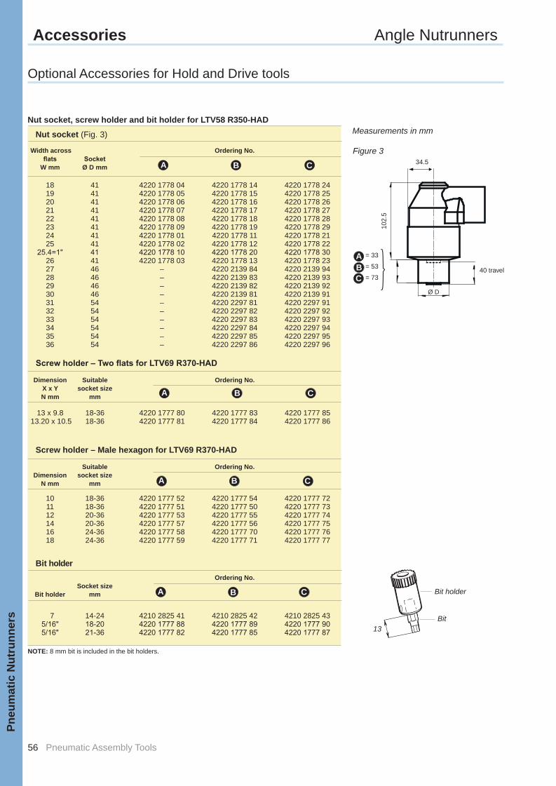
Pneu
mat
ic N
utru
nner
s
56 Pneumatic Assembly Tools
A B C
Ø D
A B C
A
CB
= 33
= 53
= 73
34.5
102
.5
A B C
A B C
Bit holder
Bit13
Nut socket (Fig. 3)
Width across Ordering No. flats Socket W mm Ø D mm
18 41 4220 1778 04 4220 1778 14 4220 1778 24 19 41 4220 1778 05 4220 1778 15 4220 1778 25 20 41 4220 1778 06 4220 1778 16 4220 1778 26 21 41 4220 1778 07 4220 1778 17 4220 1778 27 22 41 4220 1778 08 4220 1778 18 4220 1778 28 23 41 4220 1778 09 4220 1778 19 4220 1778 29 24 41 4220 1778 01 4220 1778 11 4220 1778 21 25 41 4220 1778 02 4220 1778 12 4220 1778 22 25.4=1" 41 4220 1778 10 4220 1778 20 4220 1778 30 26 41 4220 1778 03 4220 1778 13 4220 1778 23 27 46 – 4220 2139 84 4220 2139 94 28 46 – 4220 2139 83 4220 2139 93 29 46 – 4220 2139 82 4220 2139 92 30 46 – 4220 2139 81 4220 2139 91 31 54 – 4220 2297 81 4220 2297 91 32 54 – 4220 2297 82 4220 2297 92 33 54 – 4220 2297 83 4220 2297 93 34 54 – 4220 2297 84 4220 2297 94 35 54 – 4220 2297 85 4220 2297 95 36 54 – 4220 2297 86 4220 2297 96
Figure 3
40 travel
Bit holder Ordering No. Socket size Bit holder mm
7 14-24 4210 2825 41 4210 2825 42 4210 2825 43 5/16" 18-20 4220 1777 88 4220 1777 89 4220 1777 90 5/16" 21-36 4220 1777 82 4220 1777 85 4220 1777 87
Optional Accessories for Hold and Drive tools
Nut socket, screw holder and bit holder for LTV58 R350-HAD
NOTE: 8 mm bit is included in the bit holders.
Measurements in mm
Accessories Angle Nutrunners
Screw holder – Two flats for LTV69 R370-HAD
Dimension Suitable Ordering No. X x Y socket size N mm mm
13 x 9.8 18-36 4220 1777 80 4220 1777 83 4220 1777 85 13.20 x 10.5 18-36 4220 1777 81 4220 1777 84 4220 1777 86
Screw holder – Male hexagon for LTV69 R370-HAD
Suitable Ordering No. Dimension socket size N mm mm
10 18-36 4220 1777 52 4220 1777 54 4220 1777 72 11 18-36 4220 1777 51 4220 1777 50 4220 1777 73 12 20-36 4220 1777 53 4220 1777 55 4220 1777 74 14 20-36 4220 1777 57 4220 1777 56 4220 1777 75 16 24-36 4220 1777 58 4220 1777 70 4220 1777 76 18 24-36 4220 1777 59 4220 1777 71 4220 1777 77
Am_Nutrunners.indd 56 2012-02-06 10:51:07
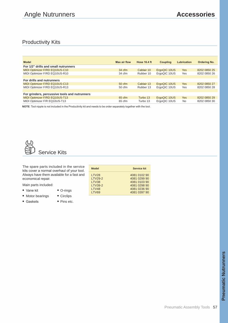
Pneu
mat
ic N
utru
nner
s
Pneumatic Assembly Tools 57
Angle Nutrunners Accessories
Model Service kit
LTV28 4081 0102 90LTV29-2 4081 0299 90LTV38 4081 0103 90LTV39-2 4081 0298 90LTV48 4081 0236 90LTV69 4081 0397 90
Service Kits
The spare parts included in the service kits cover a normal overhaul of your tool. Always have them available for a fast and economical repair.
Main parts included:l Vane kit l O-ringsl Motor bearings l Circlipsl Gaskets l Pins etc.
Model Max air flow Hose 16.4 ft Coupling Lubrication Ordering No.For 1/2" drills and small nutrunners MIDI Optimizer F/RD EQ10US-C10 34 cfm Cablair 10 ErgoQIC 10US Yes 8202 0850 25MIDI Optimizer F/RD EQ10US-R10 34 cfm Rubber 10 ErgoQIC 10US Yes 8202 0850 26 For drills and nutrunners MIDI Optimizer F/RD EQ10US-C13 50 cfm Cablair 13 ErgoQIC 10US Yes 8202 0850 27MIDI Optimizer F/RD EQ10US-R13 50 cfm Rubber 13 ErgoQIC 10US Yes 8202 0850 28 For grinders, percussive tools and nutrunners MIDI Optimizer F/RD EQ10US-T13 65 cfm Turbo 13 ErgoQIC 10US Yes 8202 0850 29MIDI Optimizer F/R EQ10US-T13 65 cfm Turbo 13 ErgoQIC 10US No 8202 0850 30
Productivity Kits
NOTE: Tool nipple is not included in the Productivity kit and needs to be order separately together with the tool.
Am_Nutrunners.indd 57 2012-02-06 10:51:07
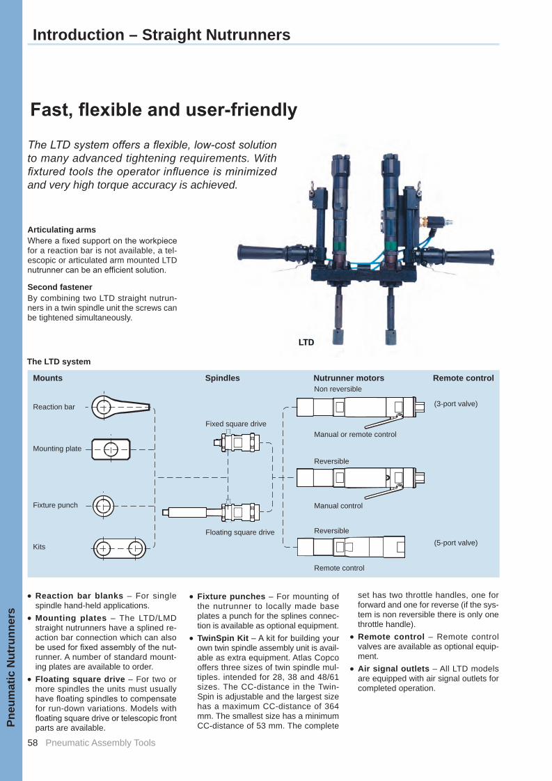
Pneu
mat
ic N
utru
nner
s
58 Pneumatic Assembly Tools
l Reaction bar blanks – For single spindle hand-held applications.
l Mounting plates – The LTD/LMD straight nutrunners have a splined re-action bar connection which can also be used for fi xed assembly of the nut-runner. A number of standard mount-ing plates are available to order.
l Floating square drive – For two or more spindles the units must usually have fl oating spindles to compensate for run-down variations. Models with fl oating square drive or telescopic front parts are available.
l Fixture punches – For mounting of the nutrunner to locally made base plates a punch for the splines connec-tion is available as optional equipment.
l TwinSpin Kit – A kit for building your own twin spindle assembly unit is avail-able as extra equipment. Atlas Copco offers three sizes of twin spindle mul-tiples. intended for 28, 38 and 48/61 sizes. The CC-distance in the Twin-Spin is adjustable and the larg est size has a maximum CC-distance of 364 mm. The smallest size has a min i mum CC-dis tance of 53 mm. The com plete
set has two throttle handles, one for forward and one for reverse (if the sys-tem is non re vers i ble there is only one throttle handle).
l Remote control – Remote control valves are available as optional equip-ment.
l Air signal outlets – All LTD models are equipped with air signal outlets for completed operation.
Mounts Spindles Nutrunner motors Remote control
Reaction bar
Mounting plate
Fixture punch
Kits
Fixed square drive
Floating square drive
Non reversible
Manual or remote control
Reversible
Manual control
Reversible
Remote control
(3-port valve)
(5-port valve)
Introduction – Straight Nutrunners
The LTD system offers a fl exible, low-cost solution to many advanced tightening requirements. With fi xtured tools the operator infl uence is minimized and very high torque accuracy is achieved.
Fast, fl exible and user-friendly
Articulating arms Where a fi xed support on the workpiece for a reaction bar is not available, a tel-escopic or articulated arm mounted LTD nutrunner can be an effi cient solution.
Second fastener By combining two LTD straight nutrun-ners in a twin spindle unit the screws can be tightened simultaneously.
The LTD system
Am_Nutrunners.indd 58 2012-02-06 10:51:08
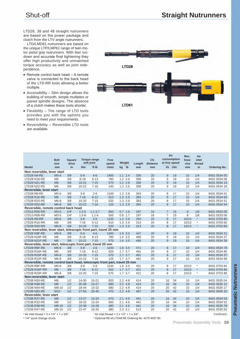
Pneu
mat
ic N
utru
nner
s
Pneumatic Assembly Tools 59
Air Rec. Air Bolt Square Torque range Free CS consumption hose inlet size drive soft joint speed Weight Length distance at free speed size thread Model mm in Nm ft lb r/min kg lb mm mm l/s cfm mm in Ordering No.Non reversible, lever startLTD28 N9-RE M5-6 3/8 5-9 4-6 1400 1.1 2.4 339 20 9 19 10 1/4 8431 0534 05LTD28 N18-RE M6 3/8 8-18 6-13 780 1.2 2.6 358 20 9 19 10 1/4 8431 0534 08LTD28 N21-RE M6 3/8 10-21 7-15 570 1.2 2.6 358 20 9 19 10 1/4 8431 0534 13LTD28 N22-RE M6 3/8 10-22 7-16 140 1.2 2.6 358 20 9 19 10 1/4 8431 0534 18Reversible, lever startLTD28 R8-RE M5-6 3/8 3-8 2-6 1100 1.2 2.6 363 20 8 17 10 1/4 8431 0534 61LTD28 R16-RE M6 3/8 7-16 6-12 610 1.3 2.9 383 20 8 17 10 1/4 8431 0534 65LTD28 R20-RE M6-8 3/8 10-20 7-15 520 1.3 2.9 383 20 8 17 10 1/4 8431 0534 51LTD28 R22-RE M6-8 3/8 10-22 7-16 125 1.3 2.9 383 20 8 17 10 1/4 8431 0534 54Reversible, remote control back headLTD13 R05-RR M3-5 1/4b 1.5-5 1.1-3.7 850 0.7 1.6 197 16 7 15 8 1/8 8431 0533 05LTD13 R08-RR M3-5 1/4b 1.5-8 1.1-6 500 0.8 1.7 197 16 7 15 8 1/8 8431 0533 06LTD28 R8-RR M5-6 3/8 3-8 2-6 1100 1.2 2.6 294 20 8 17 10/13 a 8431 0703 80LTD28 R16-RR M6 3/8 7-16 6-12 610 1.3 2.9 313 20 8 17 10/13 a 8431 0703 82LTD28 R20-RR M6-8 3/8 10-20 7-15 520 1.3 2.9 313 20 8 17 10/13 a 8431 0703 83Non reversible, lever start, telescopic front part, travel 25 mmLTD28 N9F-RE M5-6 3/8 5-9 4-6 1400 1.5 3.3 447 20 9 19 10 1/4 8431 0534 21LTD28 N18F-RE M6 3/8 8-18 6-13 780 1.6 3.5 466 20 9 19 10 1/4 8431 0534 27LTD28 N21F-RE M6 3/8 10-21 7-15 570 1.6 3.5 466 20 9 19 10 1/4 8431 0534 39Reversible, lever start, telescopic front part, travel 25 mmLTD28 R8F-RE M5-6 3/8 3-8 2-6 1100 1.6 3.5 471 20 8 17 10 1/4 8431 0534 78LTD28 R16F-RE M6 3/8 7-16 6-12 620 1.7 3.7 491 20 8 17 10 1/4 8431 0534 85LTD28 R20F-RE M6-8 3/8 10-20 7-15 570 1.7 3.7 491 20 8 17 10 1/4 8431 0534 37LTD28 R22F-RE M6-8 3/8 10-22 7-16 125 1.7 3.7 491 20 8 17 10 1/4 8431 0534 89Reversible, remote control back head, telescopic front part, travel 25 mm LTD28 R8F-RR M5-6 3/8 3-8 2-6 1100 1.6 3.5 401 20 8 17 10/13 a 8431 0703 84LTD28 R16F-RR M6 3/8 7-16 6-12 620 1.7 3.7 421 20 8 17 10/13 a 8431 0703 86LTD28 R20F-RR M6-8 3/8 10-20 7-15 570 1.7 3.7 421 20 8 17 10/13 a 8431 0703 88Non-reversible, lever startLTD38 N30-RE M8 1/2 14-30 10-21 820 2.2 4.8 414 20 16 34 10 1/4 8431 0535 04LTD38 N38-RE M8 1/2 20-38 15-27 680 2.2 4.8 414 20 16 34 10 1/4 8431 0535 12LTD38 N44-RE M8-10 1/2 18-44 13-32 580 2.2 4.8 414 20 20 42 10 1/4 8431 0535 17LTD38 N55-RE M10 1/2 27-55 20-40 470 2.2 4.8 487 20 20 42 10 1/4 8431 0535 20Reversible, lever startLTD38 R27-RE M8 1/2 13-27 10-20 670 2.1 4.6 441 20 16 34 10 1/4 8431 0534 53LTD38 R32-RE M8 1/2 18-32 13-24 560 2.1 4.6 441 20 16 34 10 1/4 8431 0534 52LTD38 R38-RE M8-10 1/2 19-38 14-28 480 2.1 4.6 441 20 16 34 10 1/4 8431 0535 78LTD38 R47-RE M8-10 1/2 22-47 16-35 380 2.3 5.1 513 20 20 42 10 1/4 8431 0535 83
LTD28, 38 and 48 straight nutrunners are based on the power pack age and clutch from the LTV angle nutrunners.
LTD/LMD61 nutrunners are based on the unique LTP/LMP61 range of twin mo-tor pistol grip nutrunners. With fast run-down and accurate fi nal tightening they offer high productivity and unmatched torque accuracy as well as joint inde-pendence.l Remote control back head – A re mote
valve is connected to the back head of the LTD-RR tools allowing a better multiple.
l Accessibility – Slim design allows the building of smooth, simple mul ti ples or paired splndle designs. The absence of a clutch makes these tools shorter.
l Flexibility – The range of LTD tools pro vides you with the options you need to meet your requirements.
l Reversibility – Reversible LTD tools are available.
Shut-off Straight Nutrunners
Continued...a Air inlet thread = 2 x 1/4" + 1 x 3/8".b 1/4" quick change chuck.
c Air inlet thread = 2 x 1/2" + 1 x 3/4".d Optional RE kit LTD48 RE Ordering No. 4210 4057 90.
Am_Nutrunners.indd 59 2012-02-06 10:51:09

Pneu
mat
ic N
utru
nner
s
60 Pneumatic Assembly Tools
Air Rec. Air Bolt Square Torque range Free consumption hose inlet size drive soft joint speed Weight Length CS distance at free speed size thread Model mm in Nm ft lb r/min kg lb mm mm l/s cfm mm in Ordering No.Reversible, remote control back headLTD38 R27-RR M8 1/2 13-27 10-20 670 2.1 4.6 377 21 16 34 10/16 a 8431 0704 22LTD38 R32-RR M8 1/2 18-32 13-24 560 2.1 4.6 377 21 16 34 10/16 a 8431 0704 24LTD38 R38-RR M8-10 1/2 19-38 14-28 480 2.1 4.6 377 21 16 34 10/16 a 8431 0704 26LTD38 R47-RR M8-10 1/2 22-47 16-35 380 2.3 5.1 448 21 16 34 10/16 a 8431 0704 28Non-reversible, lever start, telescopic front part, travel 25 mmLTD38 N30F-RE M8 1/2 14-30 10-21 820 2.3 5.0 521 20 20 42 10 1/4 8431 0535 38LTD38 N38F-RE M8 1/2 20-38 15-27 680 2.3 5.0 521 20 20 42 10 1/4 8431 0535 46LTD38 N44F-RE M8-10 1/2 18-44 13-32 580 2.3 5.0 521 20 20 42 10 1/4 8431 0535 31LTD38 N55F-RE M10 1/2 27-55 20-40 470 2.5 5.5 599 23 20 42 10 1/4 8431 0535 53Reversible, lever start, telescopic front part, travel 25 mmLTD38 R27F-RE M8 1/2 13-27 10-20 670 2.5 5.5 546 20 16 34 10 1/4 8431 0535 65LTD38 R32F-RE M8 1/2 18-32 13-24 560 2.5 5.5 546 20 16 34 10 1/4 8431 0535 91LTD38 R38F-RE M8-10 1/2 19-38 14-28 480 2.5 5.5 546 20 16 34 10 1/4 8431 0535 95LTD38 R47F-RE M8-10 1/2 22-47 16-35 380 2.7 5.9 625 23 16 34 10 1/4 8431 0535 99Reversible, remote control back head, telescopic front part, travel 25 mmLTD38 R27F-RR M8 1/2 13-27 10-20 670 2.5 5.5 482 21 16 34 10/16 a 8431 0704 30LTD38 R32F-RR M8 1/2 18-32 13-24 560 2.5 5.5 482 21 16 34 10/16 a 8431 0704 32LTD38 R38F-RR M8-10 1/2 19-38 14-28 480 2.5 5.5 482 21 16 34 10/16 a 8431 0704 34LTD38 R47F-RR M8-10 1/2 22-47 16-35 380 2.7 5.9 566 23 16 34 10/16 a 8431 0704 36Reversible, lever startLTD48 R65-RE M10 1/2 27-65 20-48 400 3.1 6.8 582 30 28 59 12.5 1/2 8431 0637 07LTD48 R81-RE M12 1/2 32-81 24-60 320 3.1 6.8 582 30 28 59 12.5 1/2 8431 0637 12Reversible, remote control back headLTD48 R65-RR M10 1/2 27-65 20-48 400 3.5 7.7 410 28 30 63 12.5/16 c 8431 0704 46LTD48 R81-RR M12 1/2 32-81 24-60 330 3.5 7.7 410 28 30 63 12.5/16 c 8431 0704 48Reversible, lever start, telescopic front part, travel 25 mmLTD48 R65F-RE M10 1/2 27-65 20-48 400 3.5 7.7 700 30 28 59 12.5 1/2 8431 0637 17LTD48 R81F-RE M12 1/2 32-81 24-60 320 3.5 7.7 700 30 28 59 12.5 1/2 8431 0637 23Reversible, remote control back head LTD48 R65F-RR M10 1/2 27-65 20-48 400 3.7 8.2 522 28 30 63 12.5/16 c 8431 0704 50LTD48 R81F-RR M12 1/2 32-81 24-60 330 3.7 8.2 522 28 30 63 12.5/16 c 8431 0704 52
a Air inlet thread = 2 x 1/4" + 1 x 3/8".b 1/4" quick change chuck.
Straight Nutrunners Shut-off
Air con- Air Bolt Square Torque range Min torque Free CS sumption at inlet size drive at 6.3 bar at 3 bar speed Weight Length distance free speed thread Spline Model mm in Nm ft lb Nm ft lb r/min kg lb mm mm l/s cfm in type Ordering No.Torque control models with fixed square drive LTD61 H100-13-RE M12 1/2 55-100 40-75 45 35 1800 3.0 6.6 223 29 20 42 3/8 3 8431 0808 06LTD61 H170-13-RE M14 1/2 95-170 70-125 70 50 1100 3.0 6.6 223 29 20 42 3/8 3 8431 0808 15LTD61 H230-19-RE M16 3/4 125-230 90-170 85 60 820 3.0 6.6 223 29 20 42 3/8 3 8431 0808 23LTD61 H350-20-RE M18 3/4 190-350 140-255 145 105 520 3.9 8.6 260 31 20 42 3/8 4 8431 0808 27LTD61 H500-20-RE M20 3/4 275-500 200-370 220 160 360 3.9 8.6 260 31 20 42 3/8 4 8431 0808 36LTD61 H700-25-RE M22 1 360-650 265-480 280 207 280 4.5 9.9 305 34 20 42 3/8 5 8431 0808 43LTD61 H900-25-RE M24 1 480-870 350-640 300 220 210 4.5 9.9 282 32 20 42 3/8 5 8431 0808 45
Air con- Air Bolt Square Max torque Min torque Free CS sumption at inlet size drive at 6.3 bar at 3 bar speed Weight Length distance free speed thread Spline Model mm in Nm ft lb Nm ft lb r/min kg lb mm mm l/s cfm in type Ordering No.Stall type models with fixed square driveLMD61 H100-13-RE M12 1/2 100 75 60 45 2200 3.0 6.6 223 29 20 42 3/8 3 8431 0809 02LMD61 H170-13-RE M14 1/2 170 125 100 75 1400 3.0 6.6 223 29 20 42 3/8 3 8431 0809 10LMD61 H230-19-RE M16 3/4 230 170 130 95 1000 3.0 6.6 223 29 20 42 3/8 3 8431 0809 12LMD61 H350-20-RE M18 3/4 350 260 200 145 650 3.9 8.6 260 31 20 42 3/8 4 8431 0809 28LMD61 H500-20-RE M20 3/4 500 370 300 220 450 3.9 8.6 260 31 20 42 3/8 4 8431 0809 30LMD61 H700-25-RE M22 1 700 520 400 295 350 4.5 9.9 305 34 20 42 3/8 5 8431 0809 41LMD61 H900-25-RE M24 1 900 665 500 365 260 4.5 9.9 282 34 20 42 3/8 5 8431 0809 49
NOTE: Change over torque is around 4% of maximum torque on a given pressure.
Straight Nutrunners Non Shut-off
Straight Nutrunners Shut-off
c Air inlet thread = 2 x 1/2" + 1 x 3/4".d Optional RE kit LTD48 RE Ordering No. 4210 4057 90.
NOTE: Change over torque is around 4% of maximum torque on a given pressure.
Am_Nutrunners.indd 60 2012-02-06 10:51:09
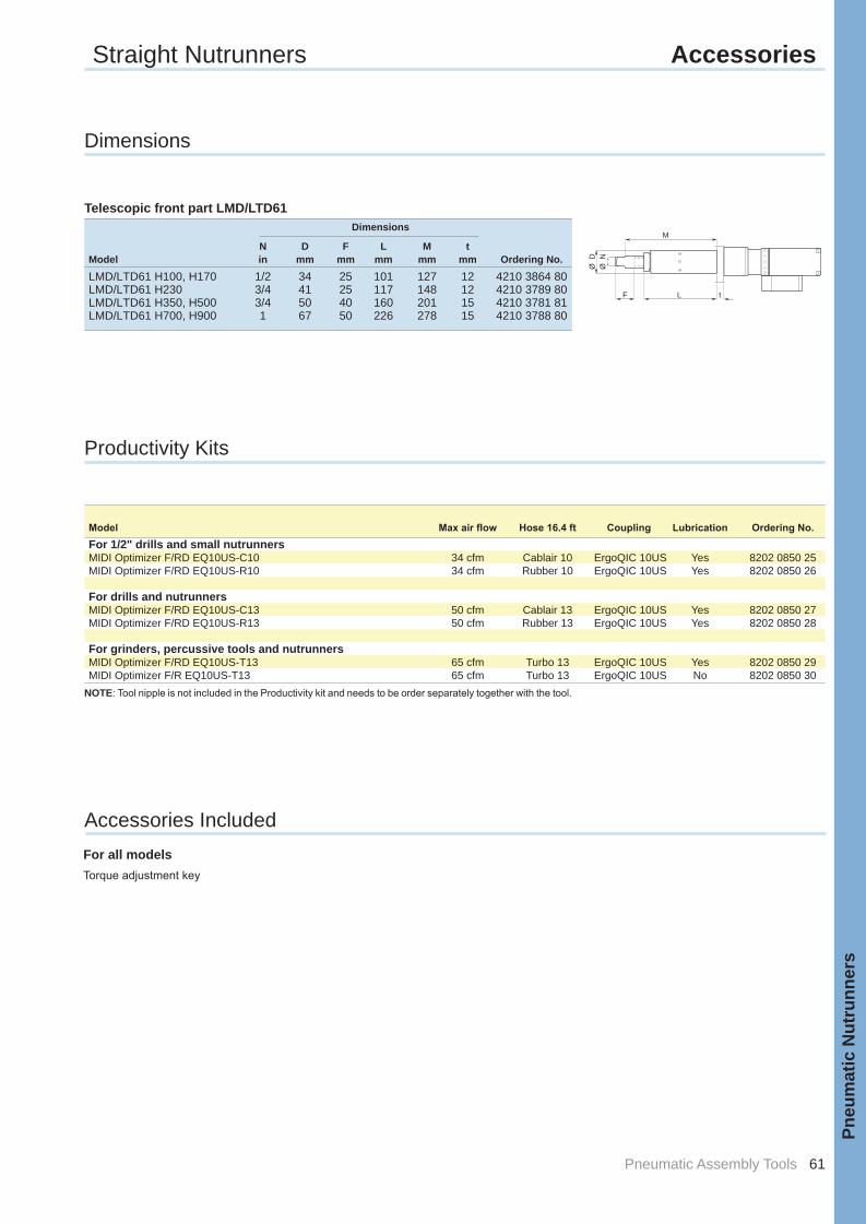
Pneu
mat
ic N
utru
nner
s
Pneumatic Assembly Tools 61
Ø D
Ø N
M
LF t
Accessories IncludedFor all modelsTorque adjustment key
Telescopic front part LMD/LTD61 Dimensions
N D F L M tModel in mm mm mm mm mm Ordering No.LMD/LTD61 H100, H170 1/2 34 25 101 127 12 4210 3864 80LMD/LTD61 H230 3/4 41 25 117 148 12 4210 3789 80LMD/LTD61 H350, H500 3/4 50 40 160 201 15 4210 3781 81LMD/LTD61 H700, H900 1 67 50 226 278 15 4210 3788 80
Straight Nutrunners Accessories
Dimensions
Productivity Kits
Model Max air flow Hose 16.4 ft Coupling Lubrication Ordering No.For 1/2" drills and small nutrunners MIDI Optimizer F/RD EQ10US-C10 34 cfm Cablair 10 ErgoQIC 10US Yes 8202 0850 25MIDI Optimizer F/RD EQ10US-R10 34 cfm Rubber 10 ErgoQIC 10US Yes 8202 0850 26 For drills and nutrunners MIDI Optimizer F/RD EQ10US-C13 50 cfm Cablair 13 ErgoQIC 10US Yes 8202 0850 27MIDI Optimizer F/RD EQ10US-R13 50 cfm Rubber 13 ErgoQIC 10US Yes 8202 0850 28 For grinders, percussive tools and nutrunners MIDI Optimizer F/RD EQ10US-T13 65 cfm Turbo 13 ErgoQIC 10US Yes 8202 0850 29MIDI Optimizer F/R EQ10US-T13 65 cfm Turbo 13 ErgoQIC 10US No 8202 0850 30
NOTE: Tool nipple is not included in the Productivity kit and needs to be order separately together with the tool.
Am_Nutrunners.indd 61 2012-02-06 10:51:10
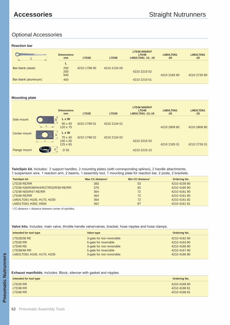
Pneu
mat
ic N
utru
nner
s
62 Pneumatic Assembly Tools
D
L
L
W
L
W
LTD38 N55/R47 Dimensions LTD48 LMD/LTD61 LMD/LTD61 mm LTD28 LTD38 LMD/LTD61 -13, -19 -20 -25
L 250 4210 1798 00 4210 2134 00 200 4210 2219 02 500 4210 2183 80 4210 2726 80 400 4210 2219 01
LTD38 N55/R47 Dimensions LTD48 LMD/LTD61 LMD/LTD61 mm LTD28 LTD38 LMD/LTD61 -13,-19 -20 -25
L x W 90 x 40 4210 1798 01 4210 2134 01 120 x 70 4210 2809 80 4210 2808 80
L x W 70 x 40 4210 1798 02 4210 2134 02 100 x 50 4210 2219 03 125 x 65 4210 2183 01 4210 2726 01
D 55 4210 2219 10
Mounting plate
Side mount
Center mount
Flange mount
Bar blank (steel)
Reaction bar
Bar blank (aluminum)
TwinSpin kit. Includes: 2 support handles, 2 mounting plates (with corresponding splines), 2 handle attachments,1 suspension wire, 1 reaction arm, 2 beams, 1 assembly tool, 1 mounting plate for reaction bar, 2 posts, 2 brackets.
Valve kits. Includes: main valve, throttle handle valve/valves, bracket, hose nipples and hose clamps.
Exhaust manifolds. Includes: Block, silencer with gasket and nipples.
a CC-distance = distance between center of spindles.
TwinSpin kit Max CC-distancea Min CC-distancea Ordering No.LTD28 RE/RR 383 53 4210 4159 80LTD38 N30/N38/N44/R27/R32/R38-RE/RR 376 60 4210 4160 80LTD38 N55/R47-RE/RR 364 72 4210 4161 80LTD48 RE/RR 364 72 4210 4161 80LMD/LTD61 H100, H170, H230 364 72 4210 4161 82LMD/LTD61 H350, H500 362 87 4210 4161 81
Intended for tool type Valve type Ordering No.
LTD28/38 RE 3-gate for non reversible 4210 4162 80LTD28 RR 5-gate for reversible 4210 4163 80LTD48 RE 3-gate for non reversible 4210 4166 80LTD38/48 RR 5-gate for reversible 4210 4167 80LMD/LTD61 H100, H170, H230 3-gate for non reversible 4210 4166 80
Intended for tool type Ordering No.
LTD28 RR 4210 4168 80LTD38 RR 4210 4168 81LTD48 RR 4210 4168 81
Accessories Straight Nutrunners
Optional Accessories
Am_Nutrunners.indd 62 2012-02-06 10:51:14
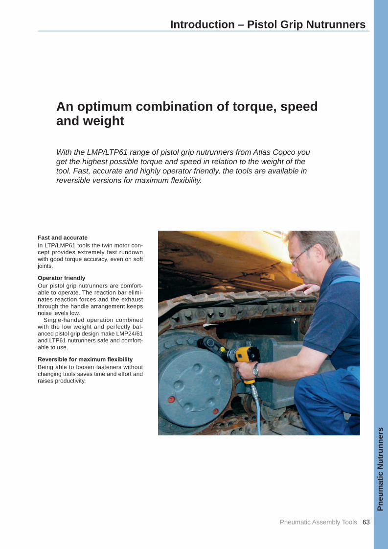
Pneu
mat
ic N
utru
nner
s
Pneumatic Assembly Tools 63
Introduction – Pistol Grip Nutrunners
With the LMP/LTP61 range of pistol grip nutrunners from Atlas Copco you get the highest possible torque and speed in relation to the weight of the tool. Fast, accurate and highly operator friendly, the tools are available in reversible versions for maximum flexibility.
Fast and accurateIn LTP/LMP61 tools the twin motor con-cept provides extremely fast rundown with good torque accuracy, even on soft joints.
Operator friendlyOur pistol grip nutrunners are comfort-able to operate. The reaction bar elimi-nates reaction forces and the exhaust through the handle arrangement keeps noise levels low.
Single-handed operation combined with the low weight and perfectly bal-anced pistol grip design make LMP24/61 and LTP61 nutrunners safe and comfort-able to use.
Reversible for maximum flexibilityBeing able to loosen fasteners without changing tools saves time and effort and raises productivity.
An optimum combination of torque, speed and weight
Am_Nutrunners.indd 63 2012-02-10 11:37:28
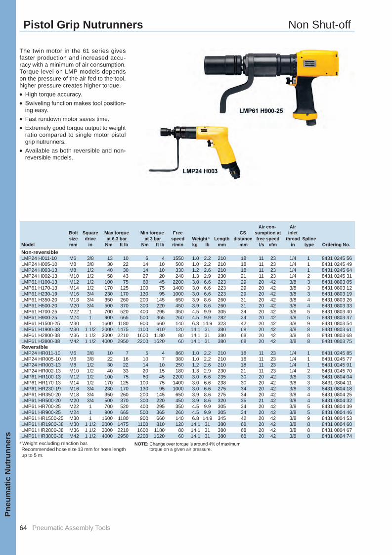
Pneu
mat
ic N
utru
nner
s
64 Pneumatic Assembly Tools
The twin motor in the 61 series gives fast er production and increased accu-racy with a minimum of air consumption. Torque level on LMP models depends on the pressure of the air fed to the tool, higher pressure creates higher torque.l High torque accuracy.l Swiveling function makes tool position-
ing easy.l Fast rundown motor saves time.l Extremely good torque output to weight
ratio compared to single motor pis tol grip nutrunners.
l Available as both reversible and non-reversible models.
Air con- Air Bolt Square Max torque Min torque Free CS sumption at inlet size drive at 6.3 bar at 3 bar speed Weight a Length distance free speed thread Spline Model mm in Nm ft lb Nm ft lb r/min kg lb mm mm l/s cfm in type Ordering No.Non-reversible LMP24 H011-10 M6 3/8 13 10 6 4 1550 1.0 2.2 210 18 11 23 1/4 1 8431 0245 56LMP24 H005-10 M8 3/8 30 22 14 10 500 1.0 2.2 210 18 11 23 1/4 1 8431 0245 49LMP24 H003-13 M8 1/2 40 30 14 10 330 1.2 2.6 210 18 11 23 1/4 1 8431 0245 64LMP24 H002-13 M10 1/2 58 43 27 20 240 1.3 2.9 230 21 11 23 1/4 2 8431 0245 31LMP61 H100-13 M12 1/2 100 75 60 45 2200 3.0 6.6 223 29 20 42 3/8 3 8431 0803 05LMP61 H170-13 M14 1/2 170 125 100 75 1400 3.0 6.6 223 29 20 42 3/8 3 8431 0803 12LMP61 H230-19 M16 3/4 230 170 130 95 1000 3.0 6.6 223 29 20 42 3/8 3 8431 0803 19LMP61 H350-20 M18 3/4 350 260 200 145 650 3.9 8.6 260 31 20 42 3/8 4 8431 0803 26LMP61 H500-20 M20 3/4 500 370 300 220 450 3.9 8.6 260 31 20 42 3/8 4 8431 0803 33LMP61 H700-25 M22 1 700 520 400 295 350 4.5 9.9 305 34 20 42 3/8 5 8431 0803 40LMP61 H900-25 M24 1 900 665 500 365 260 4.5 9.9 282 34 20 42 3/8 5 8431 0803 47LMP61 H1500-25 M30 1 1600 1180 900 660 140 6.8 14.9 323 42 20 42 3/8 9 8431 0803 54LMP61 H1900-38 M30 1 1/2 2000 1475 1100 810 120 14.1 31 380 68 20 42 3/8 8 8431 0803 61LMP61 H2800-38 M36 1 1/2 3000 2210 1600 1180 80 14.1 31 380 68 20 42 3/8 8 8431 0803 68LMP61 H3800-38 M42 1 1/2 4000 2950 2200 1620 60 14.1 31 380 68 20 42 3/8 8 8431 0803 75Reversible LMP24 HR011-10 M6 3/8 10 7 5 4 860 1.0 2.2 210 18 11 23 1/4 1 8431 0245 85LMP24 HR005-10 M8 3/8 22 16 10 7 380 1.0 2.2 210 18 11 23 1/4 1 8431 0245 77LMP24 HR003-13 M8 1/2 30 22 14 10 250 1.2 2.6 210 18 11 23 1/4 1 8431 0245 91LMP24 HR002-13 M10 1/2 40 33 20 15 180 1.3 2.9 230 21 11 23 1/4 2 8431 0245 70LMP61 HR100-13 M12 1/2 100 75 60 45 2200 3.0 6.6 235 30 20 42 3/8 3 8431 0804 04LMP61 HR170-13 M14 1/2 170 125 100 75 1400 3.0 6.6 238 30 20 42 3/8 3 8431 0804 11LMP61 HR230-19 M16 3/4 230 170 130 95 1000 3.0 6.6 275 34 20 42 3/8 3 8431 0804 18LMP61 HR350-20 M18 3/4 350 260 200 145 650 3.9 8.6 275 34 20 42 3/8 4 8431 0804 25LMP61 HR500-20 M20 3/4 500 370 300 220 450 3.9 8.6 320 35 21 42 3/8 4 8431 0804 32LMP61 HR700-25 M22 1 700 520 400 295 350 4.5 9.9 305 34 20 42 3/8 5 8431 0804 39LMP61 HR900-25 M24 1 900 665 500 365 260 4.5 9.9 305 34 20 42 3/8 5 8431 0804 46LMP61 HR1500-25 M30 1 1600 1180 900 660 140 6.8 14.9 345 42 20 42 3/8 9 8431 0804 53LMP61 HR1900-38 M30 1 1/2 2000 1475 1100 810 120 14.1 31 380 68 20 42 3/8 8 8431 0804 60LMP61 HR2800-38 M36 1 1/2 3000 2210 1600 1180 80 14.1 31 380 68 20 42 3/8 8 8431 0804 67LMP61 HR3800-38 M42 1 1/2 4000 2950 2200 1620 60 14.1 31 380 68 20 42 3/8 8 8431 0804 74
Pistol Grip Nutrunners Non Shut-off
a Weight excluding reaction bar.Recommended hose size 13 mm for hose length up to 5 m.
NOTE: Change over torque is around 4% of maximum torque on a given air pressure.
Am_Nutrunners.indd 64 2012-02-06 10:51:24
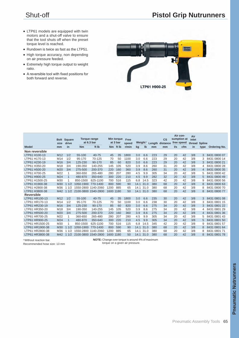
Pneu
mat
ic N
utru
nner
s
Pneumatic Assembly Tools 65
Air con- Air Bolt Square Torque range Min torque Free CS sumption at inlet size drive at 6.3 bar at 3 bar speed Weight a Length distance free speed thread Spline Model mm in Nm ft lb Nm ft lb r/min kg lb mm mm l/s cfm in type Ordering No.Non reversible LTP61 H100-13 M12 1/2 55-100 40-75 45 35 1800 3.0 6.6 223 29 20 42 3/8 3 8431 0800 07LTP61 H170-13 M14 1/2 95-170 70-125 70 50 1100 3.0 6.6 223 29 20 42 3/8 3 8431 0800 14LTP61 H230-19 M16 3/4 125-230 90-170 85 60 820 3.0 6.6 223 29 20 42 3/8 3 8431 0800 21LTP61 H350-20 M18 3/4 190-350 140-255 145 105 520 3.9 8.6 260 31 20 42 3/8 4 8431 0800 28LTP61 H500-20 M20 3/4 275-500 200-370 220 160 360 3.9 8.6 260 31 20 42 3/8 4 8431 0800 35LTP61 H700-25 M22 1 360-650 265-480 280 207 280 4.5 9.9 305 34 20 42 3/8 5 8431 0800 42LTP61 H900-25 M24 1 480-870 350-640 300 220 210 4.5 9.9 282 32 20 42 3/8 5 8431 0800 49LTP61 H1500-25 M30 1 850-1500 625-1100 700 516 115 6.8 14.5 323 42 20 42 3/8 9 8431 0800 56LTP61 H1900-38 M30 1 1/2 1050-1900 770-1400 800 590 90 14.1 31.0 380 68 20 42 3/8 8 8431 0800 63LTP61 H2800-38 M36 1 1/2 1550-2800 1140-2060 1200 885 65 14.1 31.0 380 68 20 42 3/8 8 8431 0800 70LTP61 H3800-38 M42 1 1/2 2100-3800 1540-2800 1600 1180 50 14.1 31.0 380 68 20 42 3/8 8 8431 0800 77Reversible LTP61 HR100-13 M12 1/2 55-100 40-75 45 35 1800 3.0 6.6 235 30 20 42 3/8 3 8431 0801 08LTP61 HR170-13 M14 1/2 95-170 70-125 70 50 1100 3.0 6.6 238 30 20 42 3/8 3 8431 0801 15LTP61 HR230-19 M16 3/4 125-230 90-170 85 60 820 3.0 6.6 275 34 20 42 3/8 3 8431 0801 22LTP61 HR350-20 M18 3/4 190-350 140-255 145 105 520 3.9 8.6 275 34 20 42 3/8 4 8431 0801 29LTP61 HR500-20 M20 3/4 275-500 200-370 220 160 360 3.9 8.6 275 34 20 42 3/8 4 8431 0801 36LTP61 HR700-25 M22 1 360-650 265-480 280 207 280 4.5 9.9 305 34 20 42 3/8 5 8431 0801 43LTP61 HR900-25 M24 1 480-870 350-640 300 220 210 4.5 9.9 305 34 20 42 3/8 5 8431 0801 50LTP61 HR1500-25 M30 1 850-1500 625-1100 700 516 115 6.8 14.5 345 42 20 42 3/8 9 8431 0801 57LTP61 HR1900-38 M30 1 1/2 1050-1900 770-1400 800 590 90 14.1 31.0 380 68 20 42 3/8 8 8431 0801 64LTP61 HR2800-38 M36 1 1/2 1550-2800 1140-2060 1200 885 65 14.1 31.0 380 68 20 42 3/8 8 8431 0801 71LTP61 HR3800-38 M42 1 1/2 2100-3800 1540-2800 1600 1180 50 14.1 31.0 380 68 20 42 3/8 8 8431 0801 78
l LTP61 models are equipped with twin motors and a shut-off valve to ensure that the tool shuts off when the preset torque level is reached.
l Rundown is twice as fast as the LTP51.l High torque accuracy, non depending
on air pressure feeded.l Extremely high torque output to weight
ratio. l A reversible tool with fi xed positions for
both forward and reverse.
a Without reaction bar.Recommended hose size: 13 mm
NOTE: Change over torque is around 4% of maximum torque on a given air pressure.
Shut-off Pistol Grip Nutrunners
Am_Nutrunners.indd 65 2012-02-06 10:51:24
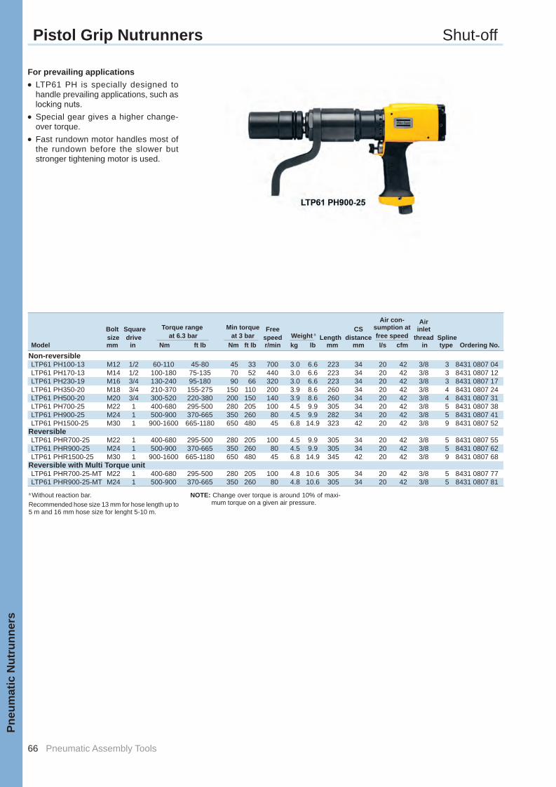
Pneu
mat
ic N
utru
nner
s
66 Pneumatic Assembly Tools
Air con- Air Bolt Square Torque range Min torque Free CS sumption at inlet size drive at 6.3 bar at 3 bar speed Weight a Length distance free speed thread Spline Model mm in Nm ft lb Nm ft lb r/min kg lb mm mm l/s cfm in type Ordering No.
Non-reversibleLTP61 PH100-13 M12 1/2 60-110 45-80 45 33 700 3.0 6.6 223 34 20 42 3/8 3 8431 0807 04LTP61 PH170-13 M14 1/2 100-180 75-135 70 52 440 3.0 6.6 223 34 20 42 3/8 3 8431 0807 12LTP61 PH230-19 M16 3/4 130-240 95-180 90 66 320 3.0 6.6 223 34 20 42 3/8 3 8431 0807 17LTP61 PH350-20 M18 3/4 210-370 155-275 150 110 200 3.9 8.6 260 34 20 42 3/8 4 8431 0807 24LTP61 PH500-20 M20 3/4 300-520 220-380 200 150 140 3.9 8.6 260 34 20 42 3/8 4 8431 0807 31LTP61 PH700-25 M22 1 400-680 295-500 280 205 100 4.5 9.9 305 34 20 42 3/8 5 8431 0807 38LTP61 PH900-25 M24 1 500-900 370-665 350 260 80 4.5 9.9 282 34 20 42 3/8 5 8431 0807 41LTP61 PH1500-25 M30 1 900-1600 665-1180 650 480 45 6.8 14.9 323 42 20 42 3/8 9 8431 0807 52
Reversible LTP61 PHR700-25 M22 1 400-680 295-500 280 205 100 4.5 9.9 305 34 20 42 3/8 5 8431 0807 55LTP61 PHR900-25 M24 1 500-900 370-665 350 260 80 4.5 9.9 305 34 20 42 3/8 5 8431 0807 62LTP61 PHR1500-25 M30 1 900-1600 665-1180 650 480 45 6.8 14.9 345 42 20 42 3/8 9 8431 0807 68
Reversible with Multi Torque unit LTP61 PHR700-25-MT M22 1 400-680 295-500 280 205 100 4.8 10.6 305 34 20 42 3/8 5 8431 0807 77LTP61 PHR900-25-MT M24 1 500-900 370-665 350 260 80 4.8 10.6 305 34 20 42 3/8 5 8431 0807 81
Pistol Grip Nutrunners Shut-off
a Without reaction bar.Recommended hose size 13 mm for hose length up to 5 m and 16 mm hose size for lenght 5-10 m.
For prevailing applicationsl LTP61 PH is specially designed to
handle prevailing applications, such as locking nuts.
l Special gear gives a higher change-over torque.
l Fast rundown motor handles most of the rundown before the slower but stronger tightening motor is used.
NOTE: Change over torque is around 10% of maxi-mum torque on a given air pressure.
Am_Nutrunners.indd 66 2012-02-06 10:51:25
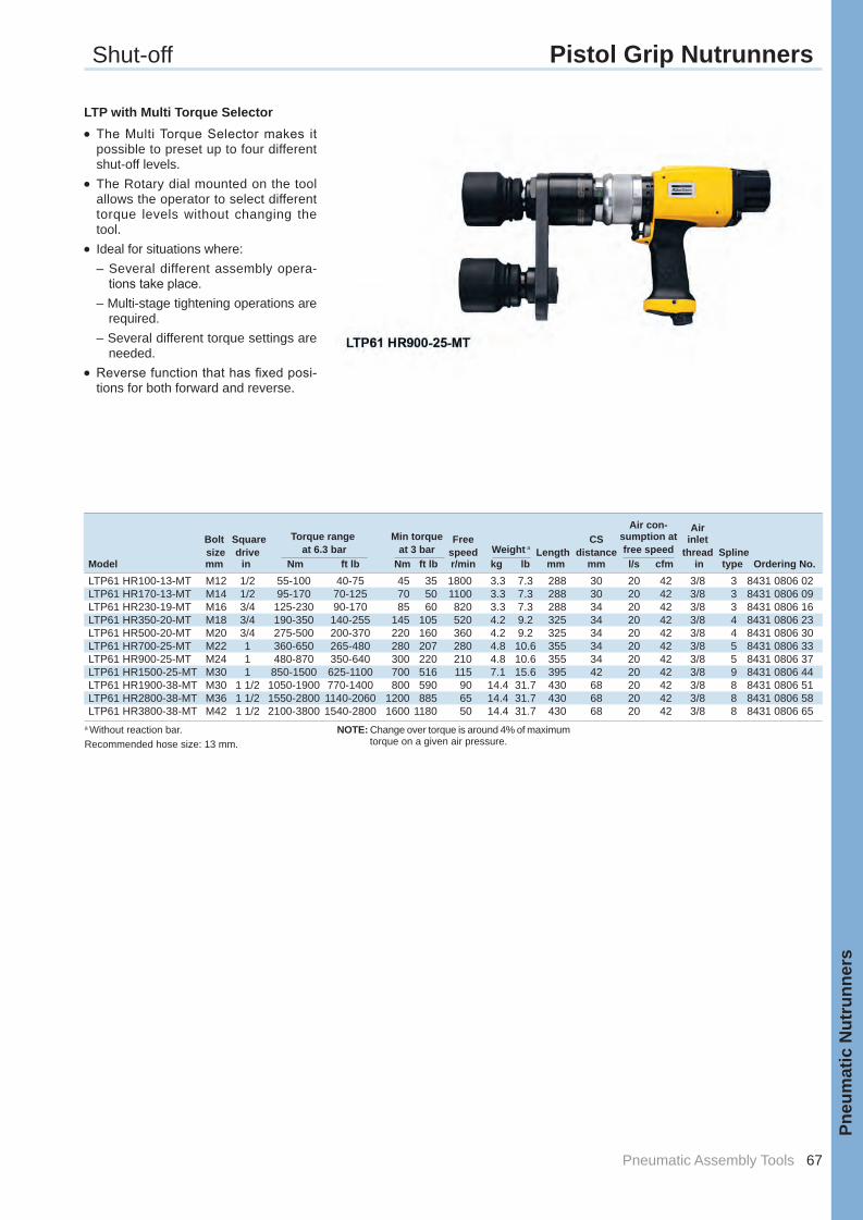
Pneu
mat
ic N
utru
nner
s
Pneumatic Assembly Tools 67
LTP with Multi Torque Selectorl The Multi Torque Selector makes it
possible to preset up to four different shut-off levels.
l The Rotary dial mounted on the tool allows the operator to select different torque levels without changing the tool.
l Ideal for situations where: – Several different assembly opera-
tions take place. – Multi-stage tightening operations are
required. – Several different torque settings are
needed.l Reverse function that has fi xed posi-
tions for both forward and reverse.
Air con- Air Bolt Square Torque range Min torque Free CS sumption at inlet size drive at 6.3 bar at 3 bar speed Weight a Length distance free speed thread Spline Model mm in Nm ft lb Nm ft lb r/min kg lb mm mm l/s cfm in type Ordering No.LTP61 HR100-13-MT M12 1/2 55-100 40-75 45 35 1800 3.3 7.3 288 30 20 42 3/8 3 8431 0806 02LTP61 HR170-13-MT M14 1/2 95-170 70-125 70 50 1100 3.3 7.3 288 30 20 42 3/8 3 8431 0806 09LTP61 HR230-19-MT M16 3/4 125-230 90-170 85 60 820 3.3 7.3 288 34 20 42 3/8 3 8431 0806 16LTP61 HR350-20-MT M18 3/4 190-350 140-255 145 105 520 4.2 9.2 325 34 20 42 3/8 4 8431 0806 23LTP61 HR500-20-MT M20 3/4 275-500 200-370 220 160 360 4.2 9.2 325 34 20 42 3/8 4 8431 0806 30LTP61 HR700-25-MT M22 1 360-650 265-480 280 207 280 4.8 10.6 355 34 20 42 3/8 5 8431 0806 33LTP61 HR900-25-MT M24 1 480-870 350-640 300 220 210 4.8 10.6 355 34 20 42 3/8 5 8431 0806 37LTP61 HR1500-25-MT M30 1 850-1500 625-1100 700 516 115 7.1 15.6 395 42 20 42 3/8 9 8431 0806 44LTP61 HR1900-38-MT M30 1 1/2 1050-1900 770-1400 800 590 90 14.4 31.7 430 68 20 42 3/8 8 8431 0806 51LTP61 HR2800-38-MT M36 1 1/2 1550-2800 1140-2060 1200 885 65 14.4 31.7 430 68 20 42 3/8 8 8431 0806 58LTP61 HR3800-38-MT M42 1 1/2 2100-3800 1540-2800 1600 1180 50 14.4 31.7 430 68 20 42 3/8 8 8431 0806 65
Shut-off Pistol Grip Nutrunners
a Without reaction bar.Recommended hose size: 13 mm.
NOTE: Change over torque is around 4% of maximum torque on a given air pressure.
Am_Nutrunners.indd 67 2012-02-06 10:51:25
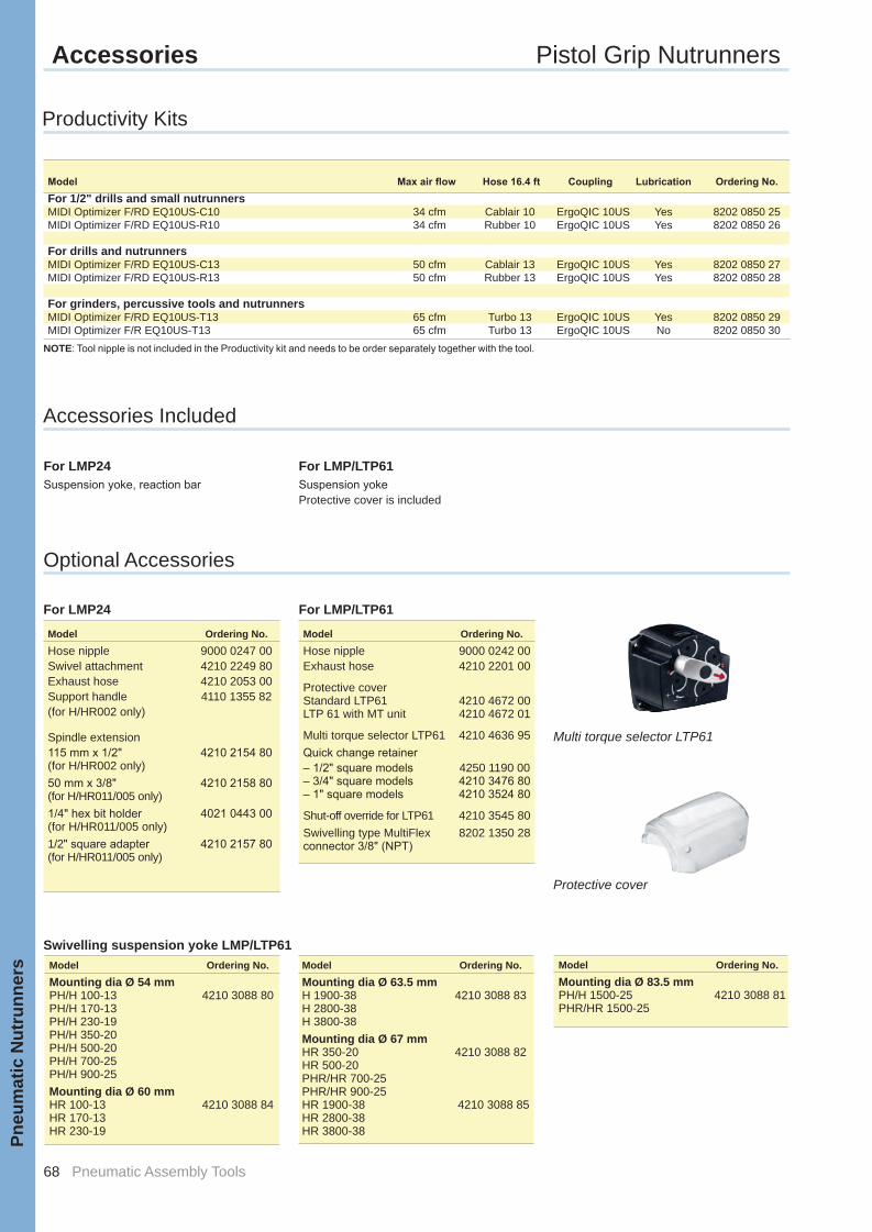
Pneu
mat
ic N
utru
nner
s
68 Pneumatic Assembly Tools
Protective cover
Multi torque selector LTP61
For LMP24
Model Ordering No.Hose nipple 9000 0247 00Swivel attachment 4210 2249 80Exhaust hose 4210 2053 00Support handle 4110 1355 82(for H/HR002 only)
Spindle extension115 mm x 1/2" 4210 2154 80(for H/HR002 only)50 mm x 3/8" 4210 2158 80(for H/HR011/005 only)1/4" hex bit holder 4021 0443 00(for H/HR011/005 only)1/2" square adapter 4210 2157 80(for H/HR011/005 only)
Accessories Pistol Grip Nutrunners
Model Max air flow Hose 16.4 ft Coupling Lubrication Ordering No.For 1/2" drills and small nutrunners MIDI Optimizer F/RD EQ10US-C10 34 cfm Cablair 10 ErgoQIC 10US Yes 8202 0850 25MIDI Optimizer F/RD EQ10US-R10 34 cfm Rubber 10 ErgoQIC 10US Yes 8202 0850 26 For drills and nutrunners MIDI Optimizer F/RD EQ10US-C13 50 cfm Cablair 13 ErgoQIC 10US Yes 8202 0850 27MIDI Optimizer F/RD EQ10US-R13 50 cfm Rubber 13 ErgoQIC 10US Yes 8202 0850 28 For grinders, percussive tools and nutrunners MIDI Optimizer F/RD EQ10US-T13 65 cfm Turbo 13 ErgoQIC 10US Yes 8202 0850 29MIDI Optimizer F/R EQ10US-T13 65 cfm Turbo 13 ErgoQIC 10US No 8202 0850 30
Optional Accessories
Accessories Included
Swivelling suspension yoke LMP/LTP61
For LMP/LTP61
Model Ordering No.Hose nipple 9000 0242 00Exhaust hose 4210 2201 00
Protective coverStandard LTP61 4210 4672 00LTP 61 with MT unit 4210 4672 01
Multi torque selector LTP61 4210 4636 95Quick change retainer– 1/2" square models 4250 1190 00– 3/4" square models 4210 3476 80– 1" square models 4210 3524 80
Shut-off override for LTP61 4210 3545 80Swivelling type MultiFlex 8202 1350 28connector 3/8" (NPT)
For LMP24Suspension yoke, reaction bar
For LMP/LTP61Suspension yokeProtective cover is included
Model Ordering No.Mounting dia Ø 54 mm PH/H 100-13 4210 3088 80PH/H 170-13 PH/H 230-19 PH/H 350-20 PH/H 500-20 PH/H 700-25 PH/H 900-25 Mounting dia Ø 60 mm HR 100-13 4210 3088 84HR 170-13 HR 230-19
Model Ordering No.Mounting dia Ø 83.5 mm PH/H 1500-25 4210 3088 81PHR/HR 1500-25
Model Ordering No.Mounting dia Ø 63.5 mm H 1900-38 4210 3088 83H 2800-38 H 3800-38 Mounting dia Ø 67 mm HR 350-20 4210 3088 82HR 500-20 PHR/HR 700-25 PHR/HR 900-25 HR 1900-38 4210 3088 85HR 2800-38 HR 3800-38
Productivity Kits
NOTE: Tool nipple is not included in the Productivity kit and needs to be order separately together with the tool.
Am_Nutrunners.indd 68 2012-02-06 10:51:28
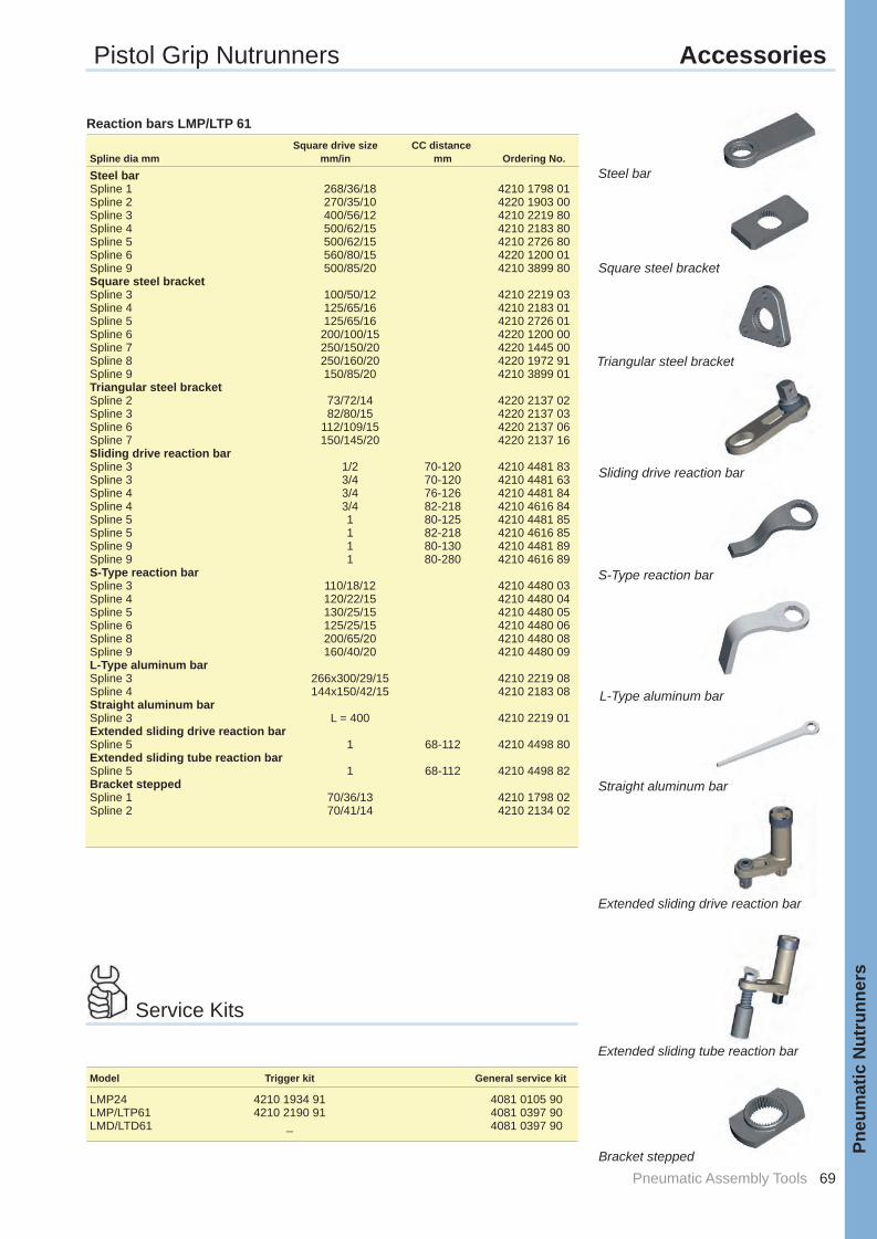
Pneu
mat
ic N
utru
nner
s
Pneumatic Assembly Tools 69
Steel bar
Square steel bracket
Triangular steel bracket
Sliding drive reaction bar
Reaction bars LMP/LTP 61
Model Trigger kit General service kit
LMP24 4210 1934 91 4081 0105 90LMP/LTP61 4210 2190 91 4081 0397 90LMD/LTD61 _ 4081 0397 90
S-Type reaction bar
Straight aluminum bar
L-Type aluminum bar
Pistol Grip Nutrunners Accessories
Extended sliding drive reaction bar
Extended sliding tube reaction bar
Square drive size CC distance Spline dia mm mm/in mm Ordering No.Steel bar Spline 1 268/36/18 4210 1798 01Spline 2 270/35/10 4220 1903 00Spline 3 400/56/12 4210 2219 80Spline 4 500/62/15 4210 2183 80Spline 5 500/62/15 4210 2726 80Spline 6 560/80/15 4220 1200 01Spline 9 500/85/20 4210 3899 80Square steel bracketSpline 3 100/50/12 4210 2219 03Spline 4 125/65/16 4210 2183 01Spline 5 125/65/16 4210 2726 01Spline 6 200/100/15 4220 1200 00Spline 7 250/150/20 4220 1445 00Spline 8 250/160/20 4220 1972 91Spline 9 150/85/20 4210 3899 01Triangular steel bracketSpline 2 73/72/14 4220 2137 02Spline 3 82/80/15 4220 2137 03Spline 6 112/109/15 4220 2137 06Spline 7 150/145/20 4220 2137 16Sliding drive reaction barSpline 3 1/2 70-120 4210 4481 83Spline 3 3/4 70-120 4210 4481 63Spline 4 3/4 76-126 4210 4481 84Spline 4 3/4 82-218 4210 4616 84Spline 5 1 80-125 4210 4481 85Spline 5 1 82-218 4210 4616 85Spline 9 1 80-130 4210 4481 89Spline 9 1 80-280 4210 4616 89S-Type reaction barSpline 3 110/18/12 4210 4480 03Spline 4 120/22/15 4210 4480 04Spline 5 130/25/15 4210 4480 05Spline 6 125/25/15 4210 4480 06Spline 8 200/65/20 4210 4480 08Spline 9 160/40/20 4210 4480 09L-Type aluminum barSpline 3 266x300/29/15 4210 2219 08Spline 4 144x150/42/15 4210 2183 08Straight aluminum barSpline 3 L = 400 4210 2219 01Extended sliding drive reaction barSpline 5 1 68-112 4210 4498 80 Extended sliding tube reaction barSpline 5 1 68-112 4210 4498 82Bracket steppedSpline 1 70/36/13 4210 1798 02Spline 2 70/41/14 4210 2134 02
Service Kits
Bracket stepped
Am_Nutrunners.indd 69 2012-02-06 10:52:00

BatteryAssembly Tools
Contents Page
Introduction ......................................... 71BCP screwdriver, clutch type .............. 73BTV nutrunners, clutch type ............... 75Tensor STB nutrunner, transducerized type ............................ 76
Am_Batteryasstools.indd 70 2012-02-06 10:59:28
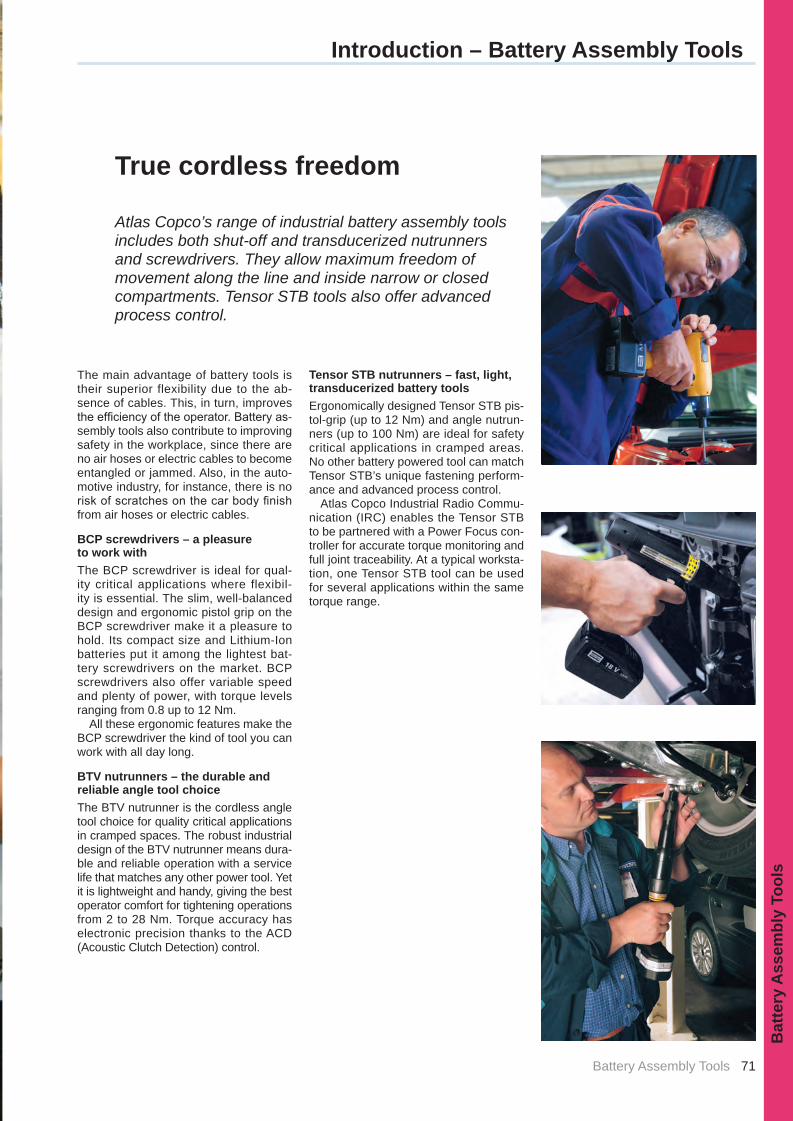
Battery Assembly Tools 71
Bat
tery
Ass
embl
y To
ols
Introduction – Battery Assembly Tools
True cordless freedom
Atlas Copco’s range of industrial battery assembly tools includes both shut-off and transducerized nutrunners and screwdrivers. They allow maximum freedom of movement along the line and inside narrow or closed compartments. Tensor STB tools also offer advanced process control.
The main advantage of battery tools is their superior flexibility due to the ab-sence of cables. This, in turn, improves the efficiency of the operator. Battery as-sembly tools also contribute to improving safety in the workplace, since there are no air hoses or electric cables to become entangled or jammed. Also, in the auto-motive industry, for instance, there is no risk of scratches on the car body finish from air hoses or electric cables.
BCP screwdrivers – a pleasure to work withThe BCP screwdriver is ideal for qual-ity critical applications where flexibil-ity is essential. The slim, well-balanced design and ergonomic pistol grip on the BCP screwdriver make it a pleasure to hold. Its compact size and Lithium-Ion batteries put it among the lightest bat-tery screwdrivers on the market. BCP screwdrivers also offer variable speed and plenty of power, with torque levels ranging from 0.8 up to 12 Nm.
All these ergonomic features make the BCP screwdriver the kind of tool you can work with all day long.
BTV nutrunners – the durable and reliable angle tool choiceThe BTV nutrunner is the cordless angle tool choice for quality critical applications in cramped spaces. The robust industrial design of the BTV nutrunner means dura-ble and reliable operation with a service life that matches any other power tool. Yet it is lightweight and handy, giving the best operator comfort for tightening operations from 2 to 28 Nm. Torque accuracy has electronic precision thanks to the ACD (Acoustic Clutch Detection) control.
Tensor STB nutrunners – fast, light, transducerized battery toolsErgonomically designed Tensor STB pis-tol-grip (up to 12 Nm) and angle nutrun-ners (up to 100 Nm) are ideal for safety critical applications in cramped areas. No other battery powered tool can match Tensor STB’s unique fastening perform-ance and advanced process control.
Atlas Copco Industrial Radio Commu-nication (IRC) enables the Tensor STB to be partnered with a Power Focus con-troller for accurate torque monitoring and full joint traceability. At a typical worksta-tion, one Tensor STB tool can be used for several applications within the same torque range.
Am_Batteryasstools.indd 71 2012-02-06 10:59:56

72 Battery Assembly Tools
Bat
tery
Ass
embl
y To
ols
Introduction – Clutch Type
For quality critical applications where flexibility is essen-tial, the BCP screwdriver and the BTV nutrunner are the ideal tool choices. Powerful and durable with superior ergonomics and operator feedback they offer higher productivity in assembly operations, independent of the industry.
Freedom – truly flexible assemblyl No product damage from cables or
hosesl No trip hazards from trailing cablesl No cable or hose managementl Speed setting functionality for the BCPl Reversible battery pack
Ergonomics – a pleasure to work withl Reduced operator fatigue and work
related health problemsl Light, compact and well-balanced designl Operator feedback
Power – high performance and durabilityl Robust and industrial tool designl Li-Ion battery technology for BCP: high
power-to-weight.
ACD-Control (Acoustic Clutch Detection) for motor control Durable grip with
optimum grip size
Slim design for best comfort and accessibility
Compact angle headwith spiral gears for durability and accuracy
Unrivalled clutch design forexcellent torque repeatability and low mean shift
Ni-Cd batteries
Two strong front lights
Signal lights for OK/NOK and battery status
Unrivalled clutch design forexcellent torque repeatabilityand low mean shift
Brushless motor and magnetic hall sensors for high durability
Slim and balanced design
Li-Ion batteries
Two strong front lights
LED for OK/NOK and battery status Buzzer option
Colour rings for marking
Speed setting unit forregulating speed
BCP Tool key features
BTV Tool key features
Powerful, durable and highlyoperator friendly
Am_Batteryasstools.indd 72 2012-02-06 11:00:22

Battery Assembly Tools 73
Bat
tery
Ass
embl
y To
ols
BCP Screwdrivers – Clutch Type
Square Weight drive Torque range Speed range (excl. battery) Length Height Model in Nm ft Ib r/min kg Ib mm mm Ordering No.BCP BL-2-I06 1/4 0.8-2.5 0.6-1.8 500-1550 0.86 1.89 200 188 8431 1273 00BCP BL-6-I06 1/4 2.0-6.0 1.5-4.4 300-1000 0.86 1.89 200 188 8431 1273 10BCP BL-8-I06 1/4 3.0-8.0 2.2-5.9 300-800 0.86 1.89 200 188 8431 1273 20BCP BL-12-I06 1/4 5.0-12.0 3.7-8.8 250-600 0.86 1.89 200 188 8431 1273 30BCP BL-2L-I06 1/4 0.8-2.5 0.6-1.8 150-440 0.86 1.89 200 188 8431 1273 50BCP BL-6L-I06 1/4 1.5-6.0 1.1-4.4 150-440 0.86 1.89 200 188 8431 1273 60BCP BL-12L-I06 1/4 3.0-12.0 2.2-8.8 150-440 0.86 1.89 200 188 8431 1273 40
-L stands for low speed models.
NOTE: The tools are set at maximum speed at delivery.
BCP screwdrivers offer true cordless freedom and superior ergonomics for the operator, thus contributing to out-standing performance.l Ergonomic, lightweight pistol-grip
design.l 7 brushless models offering variable
speed with a speed setting unit.l Torque range: 0.8-12 Nm.l Low speed models available.l Choice of two 18 V Li-Ion batteries:
1.3 Ah Flat Pack or 2.6 Ah Big Pack.
All pistol grip models have 1/4" female hexagon drive for bits with quick change chuck.
Am_Batteryasstools.indd 73 2012-02-06 11:00:23
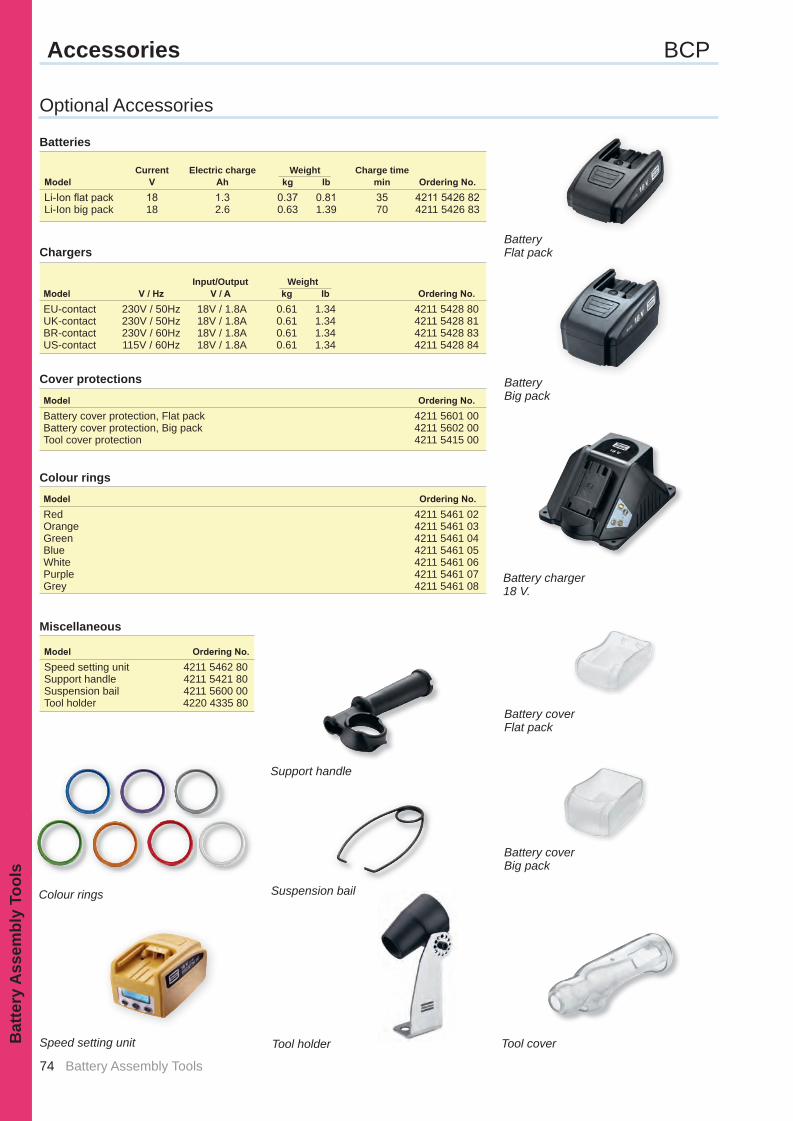
74 Battery Assembly Tools
Bat
tery
Ass
embl
y To
ols
Accessories BCP
Suspension bail
Battery coverBig pack
Battery coverFlat pack
BatteryBig pack
BatteryFlat pack
Battery charger18 V.
Support handle
Colour rings
Tool coverSpeed setting unit
Optional Accessories
Model Ordering No.Speed setting unit 4211 5462 80Support handle 4211 5421 80Suspension bail 4211 5600 00Tool holder 4220 4335 80
Current Electric charge Weight Charge time Model V Ah kg Ib min Ordering No.Li-Ion fl at pack 18 1.3 0.37 0.81 35 4211 5426 82Li-Ion big pack 18 2.6 0.63 1.39 70 4211 5426 83
Batteries
Input/Output WeightModel V / Hz V / A kg Ib Ordering No.EU-contact 230V / 50Hz 18V / 1.8A 0.61 1.34 4211 5428 80UK-contact 230V / 50Hz 18V / 1.8A 0.61 1.34 4211 5428 81BR-contact 230V / 60Hz 18V / 1.8A 0.61 1.34 4211 5428 83US-contact 115V / 60Hz 18V / 1.8A 0.61 1.34 4211 5428 84
Chargers
Cover protectionsModel Ordering No.Battery cover protection, Flat pack 4211 5601 00Battery cover protection, Big pack 4211 5602 00Tool cover protection 4211 5415 00
Model Ordering No.Red 4211 5461 02Orange 4211 5461 03Green 4211 5461 04Blue 4211 5461 05White 4211 5461 06Purple 4211 5461 07Grey 4211 5461 08
Colour rings
Miscellaneous
Tool holder
Am_Batteryasstools.indd 74 2012-02-06 11:01:23
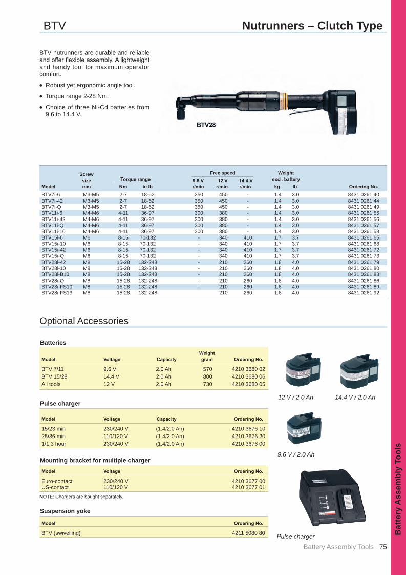
Battery Assembly Tools 75
Bat
tery
Ass
embl
y To
ols
BTV Nutrunners – Clutch Type
Screw Free speed Weight size Torque range 9.6 V 12 V 14.4 V excl. battery Model mm Nm in lb r/min r/min r/min kg lb Ordering No. BTV7i-6 M3-M5 2-7 18-62 350 450 - 1.4 3.0 8431 0261 40BTV7i-42 M3-M5 2-7 18-62 350 450 - 1.4 3.0 8431 0261 44 BTV7i-Q M3-M5 2-7 18-62 350 450 - 1.4 3.0 8431 0261 49BTV11i-6 M4-M6 4-11 36-97 300 380 - 1.4 3.0 8431 0261 55BTV11i-42 M4-M6 4-11 36-97 300 380 - 1.4 3.0 8431 0261 56BTV11i-Q M4-M6 4-11 36-97 300 380 - 1.4 3.0 8431 0261 57BTV11i-10 M4-M6 4-11 36-97 300 380 - 1.4 3.0 8431 0261 58BTV15i-6 M6 8-15 70-132 - 340 410 1.7 3.7 8431 0261 65BTV15i-10 M6 8-15 70-132 - 340 410 1.7 3.7 8431 0261 68BTV15i-42 M6 8-15 70-132 - 340 410 1.7 3.7 8431 0261 72BTV15i-Q M6 8-15 70-132 - 340 410 1.7 3.7 8431 0261 73BTV28i-42 M8 15-28 132-248 - 210 260 1.8 4.0 8431 0261 79BTV28i-10 M8 15-28 132-248 - 210 260 1.8 4.0 8431 0261 80BTV28i-B10 M8 15-28 132-248 - 210 260 1.8 4.0 8431 0261 83BTV28i-Q M8 15-28 132-248 - 210 260 1.8 4.0 8431 0261 86BTV28i-FS10 M8 15-28 132-248 - 210 260 1.8 4.0 8431 0261 89BTV28i-FS13 M8 15-28 132-248 210 260 1.8 4.0 8431 0261 92
BTV nutrunners are durable and reliable and offer fl exible assembly. A lightweight and handy tool for maximum operator comfort.
l Robust yet ergonomic angle tool.
l Torque range 2-28 Nm.
l Choice of three Ni-Cd batteries from 9.6 to 14.4 V.
WeightModel Voltage Capacity gram Ordering No.
BTV 7/11 9.6 V 2.0 Ah 570 4210 3680 02BTV 15/28 14.4 V 2.0 Ah 800 4210 3680 06All tools 12 V 2.0 Ah 730 4210 3680 05
Pulse charger
12 V / 2.0 Ah 14.4 V / 2.0 Ah
Optional Accessories
Batteries
Model Voltage Capacity Ordering No.
15/23 min 230/240 V (1.4/2.0 Ah) 4210 3676 1025/36 min 110/120 V (1.4/2.0 Ah) 4210 3676 201/1.3 hour 230/240 V (1.4/2.0 Ah) 4210 3676 00
Pulse charger
Mounting bracket for multiple chargerModel Voltage Ordering No.
Euro-contact 230/240 V 4210 3677 00US-contact 110/120 V 4210 3677 01
NOTE: Chargers are bought separately.
Suspension yoke
Model Ordering No.
BTV (swivelling) 4211 5080 80
9.6 V / 2.0 Ah
Am_Batteryasstools.indd 75 2012-02-06 11:01:36

76 Battery Assembly Tools
Bat
tery
Ass
embl
y To
ols
Introduction – Transducerized Type
Tensor STB battery powered nutrunners offer the same benefi ts in terms of process control as Tensor ST nutrunners, yet with the freedom of cordless tools. The tools have the capability to communicate with IRC or W-LAN together with a Power Focus controller, for full process control.
Flexibility – no more cablesl No more cables and cable manage-
mentl No more damaged cablesl No product damage from cablesl No trip hazards from trailing cables
Productivity – save timel Increased operator effi ciencyl Easy to set up and replacel Eliminate need for multiple operationsl Up to 100% faster than competing
products
Ergonomicsl Reduced operator fatigue and work
related health problemsl Unhindered accessl Low weight – up to 20 % lighter than
competing productsl Compact size
STB Tool key features
ST accessory bus
Same ST angle head spiral gear package
ST style motor confi gured for battery use
Confi gurable buzzer Confi gurable button standard
Li-Ion battery packagel 18V 2.6 Ah l 30V 2.6 Ah
Extremely compact electronics within the tool handle
Signal lights for operator feedbackl Tightening statusl Batch OKl Battery statusl Communication statusl Tool events
Cordless freedom with fullprocess control
Am_Batteryasstools.indd 76 2012-02-06 11:01:48
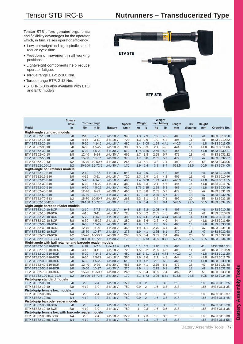
Battery Assembly Tools 77
Bat
tery
Ass
embl
y To
ols
Tensor STB IRC-B Nutrunners – Transducerized Type
Square Weight drive Torque range Speed Weight incl. battery Length CS HeightModel in Nm ft lb Battery r/min kg lb kg lb mm distance mm Ordering No.Right-angle standard models ETV STB32-10-10 3/8 2-10 2-7.5 Li-Io 18 V 943 1.3 2.9 1.9 4.2 406 11 41 8433 3010 20ETV STB32-15-10 3/8 4-15 3-11 Li-Io 18 V 720 1.3 2.9 1.9 4.2 406 11 41 8433 3010 82ETV STB32-20-10 3/8 5-20 4-14.5 Li-Io 18 V 480 1.4 3.08 1.99 4.41 440.3 14 41.8 8433 3011 05ETV STB32-30-10 3/8 6-30 4.5-22 Li-Io 18 V 380 1.5 3.3 2.1 4.6 444 14 41.8 8433 3011 66ETV STB62-30-10 3/8 6-30 4.5-22 Li-Io 30 V 610 1.75 3.85 2.65 5.8 466 14 41.8 8433 3030 21ETV STB62-40-10 3/8 12-40 9-29 Li-Io 30 V 465 1.7 3.8 2.55 5.7 479 18 47 8433 3031 22ETV STB62-50-10 3/8 15-50 10-37 Li-Io 30 V 375 1.7 3.8 2.55 5.7 479 18 47 8433 3032 67ETV STB62-70-13 1/2 15-70 10-50.7 Li-Io 30 V 265 2.3 5.1 3.2 7.1 492 20 58 8433 3033 05ETV STB62-100-13 1/2 20-100 15-72.5 Li-Io 30 V 170 2.9 6.4 3.8 8.4 528.5 22.5 60.5 8433 3034 05Right-angle ball retainer models ETV STB32-10-B10 3/8 2-10 2-7.5 Li-Io 18 V 943 1.3 2.9 1.9 4.2 406 11 41 8433 3010 30ETV STB32-15-B10 3/8 4-15 3-11 Li-Io 18 V 720 1.3 2.9 1.9 4.2 406 11 41 8433 3010 96ETV STB32-20-B10 3/8 5-20 4-14.5 Li-Io 18 V 480 1.4 3.08 1.99 4.41 440.3 14 41.8 8433 3011 15ETV STB32-30-B10 3/8 6-30 4.5-22 Li-Io 18 V 380 1.5 3.3 2.1 4.6 444 14 41.8 8433 3011 76ETV STB62-30-B10 3/8 6-30 4.5-22 Li-Io 30 V 610 1.75 3.85 2.65 5.8 466 14 41.8 8433 3030 36ETV STB62-40-B10 3/8 12-40 9-29 Li-Io 30 V 465 1.7 3.8 2.55 5.7 479 18 47 8433 3031 39ETV STB62-50-B10 3/8 15-50 10-37 Li-Io 30 V 375 1.7 3.8 2.55 5.7 479 18 47 8433 3032 75ETV STB62-70-B13 1/2 15-70 10-50.7 Li-Io 30 V 265 2.3 5.1 3.2 7.1 492 20 58 8433 3033 15ETV STB62-100-B13 1/2 20-100 15-72.5 Li-Io 30 V 170 2.9 6.4 3.8 8.4 528.5 22.5 60.5 8433 3034 15Right-angle barcode reader models ETV STB32-10-10-BCR 3/8 2-10 2-7.5 Li-Io 18 V 943 1.5 3.2 2.05 4.5 406 11 41 8433 3010 25ETV STB32-15-10-BCR 3/8 4-15 3-11 Li-Io 18 V 720 1.5 3.2 2.05 4.5 406 11 41 8433 3010 89ETV STB32-20-10-BCR 3/8 5-20 4-14.5 Li-Io 18 V 480 1.5 3.41 2.14 4.74 440.3 14 41.8 8433 3011 10ETV STB32-30-10-BCR 3/8 6-30 4.5-22 Li-Io 18 V 380 1.6 3.6 2.2 4.9 444 14 41.8 8433 3011 69ETV STB62-30-10-BCR 3/8 6-30 4.5-22 Li-Io 30 V 610 1.9 4.2 2.8 6.2 466 14 41.8 8433 3030 28ETV STB62-40-10-BCR 3/8 12-40 9-29 Li-Io 30 V 465 1.9 4.1 2.75 6.1 479 18 47 8433 3031 28ETV STB62-50-10-BCR 3/8 15-50 10-37 Li-Io 30 V 375 1.9 4.1 2.75 6.1 479 18 47 8433 3032 68ETV STB62-70-13-BCR 1/2 15-70 10-50.7 Li-Io 30 V 265 2.5 5.4 3.35 7.4 492 20 58 8433 3033 10ETV STB62-100-13-BCR 1/2 20-100 15-72.5 Li-Io 30 V 170 3.1 6.73 3.95 8.71 528.5 22.5 60.5 8433 3034 10Right-angle with ball retainer and barcode reader models ETV STB32-10-B10-BCR 3/8 2-10 2-7.5 Li-Io 18 V 943 1.5 3.2 2.05 4.5 406 11 41 8433 3010 35ETV STB32-15-B10-BCR 3/8 4-15 3-11 Li-Io 18 V 720 1.5 3.2 2.05 4.5 406 11 41 8433 3010 99ETV STB32-20-B10-BCR 3/8 5-20 4-14.5 Li-Io 18 V 480 1.5 3.41 2.14 4.74 440.3 14 41.8 8433 3011 20ETV STB32-30-B10-BCR 3/8 6-30 4.5-22 Li-Io 18 V 380 1.6 3.6 2.2 4.9 444 14 41.8 8433 3011 79ETV STB62-30-B10-BCR 3/8 6-30 4.5-22 Li-Io 30 V 610 1.9 4.2 2.8 6.2 466 14 41.8 8433 3030 38ETV STB62-40-B10-BCR 3/8 12-40 9-29 Li-Io 30 V 465 1.9 4.1 2.75 6.1 479 18 47 8433 3031 48ETV STB62-50-B10-BCR 3/8 15-50 10-37 Li-Io 30 V 375 1.9 4.1 2.75 6.1 479 18 47 8433 3032 78ETV STB62-70-B13-BCR 1/2 15-70 10-50.7 Li-Io 30 V 265 2.5 5.4 3.35 7.4 492 20 58 8433 3033 20ETV STB62-100-B13-BCR 1/2 20-100 15-72.5 Li-Io 30 V 170 3.1 6.73 3.95 8.71 528.5 22.5 60.5 8433 3034 20Pistol-grip standard models ETP STB32-06-10 3/8 2-6 2-4 Li-Io 18 V 1500 0.9 2 1.5 3.3 218 ─ 186 8433 3110 25ETP STB32-12-10 3/8 4-12 3-9 Li-Io 18 V 750 0.9 2 1.5 3.3 218 ─ 186 8433 3111 35Pistol-grip female hex models ETP STB32-06-I06 1/4 2-6 2-4 Li-Io 18 V 1500 0.9 2 1.5 3.3 218 ─ 186 8433 3110 37ETP STB32-12-I06 1/4 4-12 3-9 Li-Io 18 V 750 0.9 2 1.5 3.3 218 ─ 186 8433 3111 48Pistol-grip barcode reader models ETP STB32-06-10-BCR 3/8 2-6 2-4 Li-Io 18 V 1500 1 2.3 1.6 3.5 218 ─ 186 8433 3110 28ETP STB32-12-10-BCR 3/8 4-12 3-9 Li-Io 18 V 750 1 2.3 1.6 3.5 218 ─ 186 8433 3111 38Pistol-grip female hex with barcode reader models ETP STB32-06-I06-BCR 1/4 2-6 2-4 Li-Io 18 V 1500 1 2.3 1.6 3.5 218 ─ 186 8433 3110 38ETP STB32-12-I06-BCR 1/4 4-12 3-9 Li-Io 18 V 750 1 2.3 1.6 3.5 218 ─ 186 8433 3111 58
Tensor STB offers genuine ergonomic and fl exibility advantages for the operator which, in turn, raises operator effi ciency. l Low tool weight and high spindle speed
reduce cycle time. l Freedom of movement in all working
positions. l Lightweight components help reduce
operator fatigue.l Torque range ETV: 2-100 Nm.l Torque range ETP: 2-12 Nm.l STB IRC-B is also available with ETO
and ETC models.
Am_Batteryasstools.indd 77 2012-02-06 11:01:49
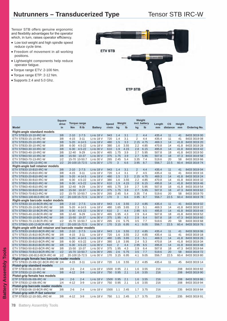
78 Battery Assembly Tools
Bat
tery
Ass
embl
y To
ols
Tensor STB offers genuine ergonomic and fl exibility advantages for the operator which, in turn, raises operator effi ciency. l Low tool weight and high spindle speed
reduce cycle time. l Freedom of movement in all working
positions. l Lightweight components help reduce
operator fatigue.l Torque range ETV: 2-100 Nm.l Torque range ETP: 2-12 Nm.l Supports 2.4 and 5.0 Ghz.
Nutrunners – Transducerized Type Tensor STB IRC-W
Square Weight drive Torque range Speed Weight incl. battery Length CS HeightModel in Nm ft lb Battery r/min kg lb kg lb mm distance mm Ordering No.Right-angle standard models ETV STB33-10-10-IRC-W 3/8 2-10 2-7.5 Li-Io 18 V 943 1.4 3.1 2 4.4 435.4 11 41 8433 3019 00ETV STB33-15-10-IRC-W 3/8 4-15 3-11 Li-Io 18 V 720 1.4 3.1 2 4.4 435.4 11 41 8433 3019 08ETV STB33-20-10-IRC-W 3/8 5-20 4-14.5 Li-Io 18 V 480 1.5 3.3 2.15 4.75 469.3 14 41.8 8433 3019 20ETV STB33-30-10-IRC-W 3/8 6-30 4.5-22 Li-Io 18 V 380 1.6 3.55 2.2 4.85 470.8 14 41.8 8433 3019 28ETV STB63-30-10-IRC-W 3/8 6-30 4.5-22 Li-Io 30 V 610 1.9 4.15 2.8 6.15 495.8 14 41.8 8433 3019 42ETV STB63-40-10-IRC-W 3/8 12-40 9-29 Li-Io 30 V 465 1.75 3.9 2.7 5.95 507.8 18 41.8 8433 3019 50ETV STB63-50-10-IRC-W 3/8 15-50 10-37 Li-Io 30 V 375 1.75 3.9 2.7 5.95 507.8 18 47.3 8433 3019 58ETV STB63-70-13-IRC-W 1/2 15-70 10-50.7 Li-Io 30 V 265 2.45 5.4 3.35 7.4 519.6 20 58 8433 3019 66ETV STB63-100-13-IRC-W 1/2 20-100 15-72.5 Li-Io 30 V 170 3 6.6 3.95 8.7 556.7 22.5 60.4 8433 3019 74Right-angle ball retainer models ETV STB33-10-B10-IRC-W 3/8 2-10 2-7.5 Li-Io 18 V 943 1.4 3.1 2 4.4 435.4 11 41 8433 3019 04ETV STB33-15-B10-IRC-W 3/8 4-15 3-11 Li-Io 18 V 720 1.4 3.1 2 4.5 435.4 11 41 8433 3019 16ETV STB33-20-B10-IRC-W 3/8 5-20 4-14.5 Li-Io 18 V 480 1.5 3.3 2.15 4.75 469.3 14 41.8 8433 3019 24ETV STB33-30-B10-IRC-W 3/8 6-30 4.5-22 Li-Io 18 V 380 1.6 3.55 2.2 4.85 470.8 14 41.8 8433 3019 32ETV STB63-30-B10-IRC-W 3/8 6-30 4.5-22 Li-Io 30 V 610 1.9 4.15 2.8 6.15 495.8 14 41.8 8433 3019 46ETV STB63-40-B10-IRC-W 3/8 12-40 9-29 Li-Io 30 V 465 1.75 3.9 2.7 5.95 507.8 18 41.8 8433 3019 54ETV STB63-50-B10-IRC-W 3/8 15-50 10-37 Li-Io 30 V 375 1.75 3.9 2.7 5.95 507.8 18 47.3 8433 3019 62ETV STB63-70-B13-IRC-W 1/2 15-70 10-50.7 Li-Io 30 V 265 2.45 5.4 3.35 7.4 519.6 20 58 8433 3019 70ETV STB63-100-B13-IRC-W 1/2 20-100 15-72.5 Li-Io 30 V 170 3 6.6 3.95 8.7 556.7 22.5 60.4 8433 3019 78Right-angle barcode reader models ETV STB33-10-10-BCR-IRC-W 3/8 2-10 2-7.5 Li-Io 18 V 943 1.6 3.55 2.2 4.85 435.4 11 41 8433 3019 02ETV STB33-20-10-BCR-IRC-W 3/8 5-20 4-14.5 Li-Io 18 V 480 1.65 3.65 2.3 5.1 469.3 14 41.8 8433 3019 22ETV STB63-30-10-BCR-IRC-W 3/8 6-30 4.5-22 Li-Io 30 V 610 2 4.4 2.95 6.5 495.8 14 41.8 8433 3019 44ETV STB63-40-10-BCR-IRC-W 3/8 12-40 9-29 Li-Io 30 V 465 1.95 4.3 2.9 6.4 507.8 18 41.8 8433 3019 52ETV STB63-50-10-BCR-IRC-W 3/8 15-50 10-37 Li-Io 30 V 375 1.95 4.3 2.9 6.4 507.8 18 47.3 8433 3019 60ETV STB63-70-13-BCR-IRC-W 1/2 15-70 10-50.7 Li-Io 30 V 265 2.6 5.75 3.5 7.7 519.6 20 58 8433 3019 68ETV STB63-100-13-BCR-IRC-W 1/2 20-100 15-72.5 Li-Io 30 V 170 3.15 6.95 4.1 9.05 556.7 22.5 60.4 8433 3019 76Right-angle with ball retainer and barcode reader models ETV STB33-10-B10-BCR-IRC-W 3/8 2-10 2-7.5 Li-Io 18 V 943 1.6 3.55 2.2 4.85 435.4 11 41 8433 3019 06ETV STB33-15-B10-BCR-IRC-W 3/8 4-15 3-11 Li-Io 18 V 720 1.6 3.55 2.2 4.85 435.4 11 41 8433 3019 18ETV STB33-20-B10-BCR-IRC-W 3/8 5-20 4-14.5 Li-Io 18 V 480 1.65 3.65 2.3 5.1 469.3 14 41.8 8433 3019 26ETV STB33-30-B10-BCR-IRC-W 3/8 6-30 4.5-22 Li-Io 18 V 380 1.8 3.95 2.4 5.3 470.8 14 41.8 8433 3019 34ETV STB63-30-B10-BCR-IRC-W 3/8 6-30 4.5-22 Li-Io 30 V 610 2 4.4 2.95 6.5 495.8 14 41.8 8433 3019 48ETV STB63-50-B10-BCR-IRC-W 3/8 15-50 10-37 Li-Io 30 V 375 1.95 4.3 2.9 6.4 507.8 18 47.3 8433 3019 64ETV STB63-70-B13-BCR-IRC-W 1/2 15-70 10-50.7 Li-Io 30 V 265 2.6 5.75 3.5 7.7 519.6 20 58 8433 3019 72ETV STB63-100-B13-BCR-IRC-W 1/2 20-100 15-72.5 Li-Io 30 V 170 3.15 6.95 4.1 9.05 556.7 22.5 60.4 8433 3019 80Right-angle female hex barcode reader models ETV STB33-15-I06-QC-BCR-IRC-W 1/4 4-15 3-11 Li-Io 18 V 720 1.6 3.55 2.2 4.85 435.4 11 45 8433 3019 14Pistol-grip standard models ETP STB33-06-10-IRC-W 3/8 2-6 2-4 Li-Io 18 V 1500 0.95 2.1 1.6 3.55 216 - 208 8433 3019 82ETP STB33-12-10-IRC-W 3/8 4-12 3-9 Li-Io 18 V 750 0.95 2.1 1.6 3.55 216 - 208 8433 3019 90Pistol-grip female hex models ETP STB33-06-I06-IRC-W 1/4 2-6 2-4 Li-Io 18 V 1500 0.95 2.1 1.6 3.55 216 - 208 8433 3019 86ETP STB33-12-I06-IRC-W 1/4 4-12 3-9 Li-Io 18 V 750 0.95 2.1 1.6 3.55 216 - 208 8433 3019 94Pistol-grip barcode reader models ETP STB33-06-10-BCR-IRC-W 3/8 2-6 2-4 Li-Io 18 V 1500 1.1 2.45 1.7 3.75 216 - 235 8433 3019 84Pistol-grip with P-Set selector ETP STB33-12-10-SEL-IRC-W 3/8 4-12 3-9 Li-Io 18 V 750 1.1 2.45 1.7 3.75 216 - 235 8433 3019 91
Am_Batteryasstools.indd 78 2012-02-06 11:01:49
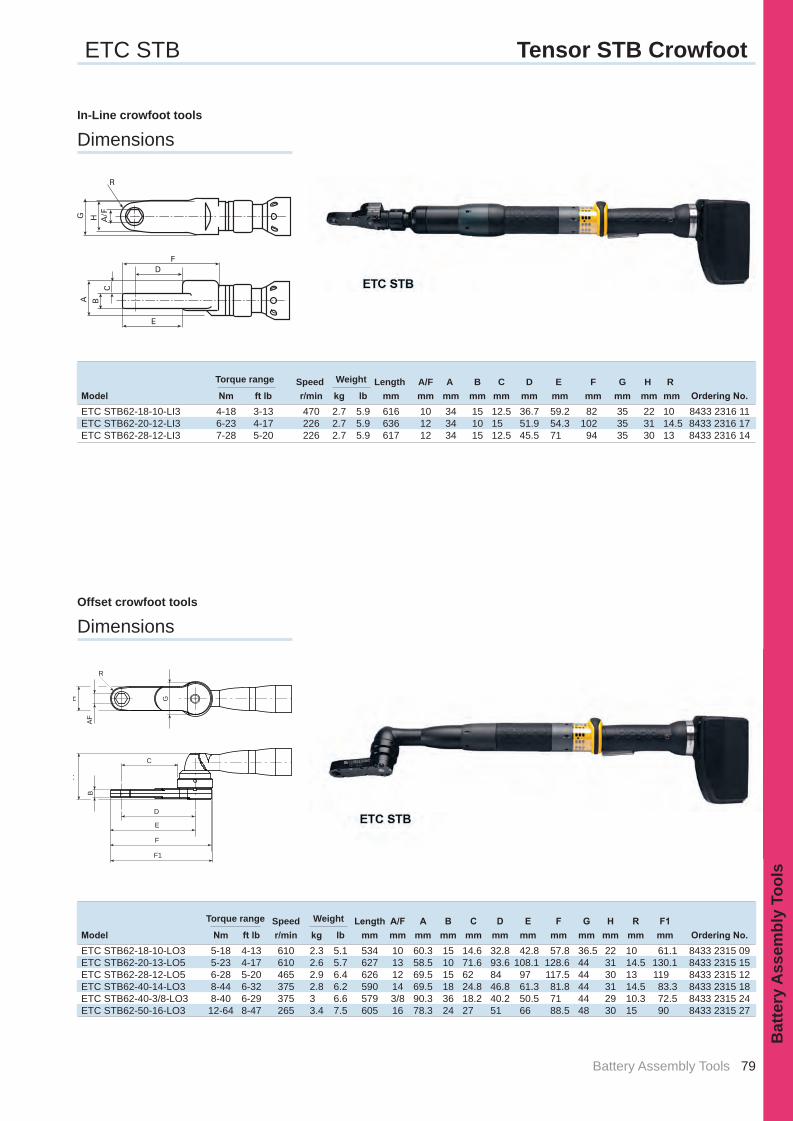
Battery Assembly Tools 79
Bat
tery
Ass
embl
y To
ols
ETC STB Tensor STB Crowfoot
Torque range Speed Weight Length A/F A B C D E F G H R Model Nm ft lb r/min kg lb mm mm mm mm mm mm mm mm mm mm mm Ordering No.ETC STB62-18-10-LI3 4-18 3-13 470 2.7 5.9 616 10 34 15 12.5 36.7 59.2 82 35 22 10 8433 2316 11ETC STB62-20-12-LI3 6-23 4-17 226 2.7 5.9 636 12 34 10 15 51.9 54.3 102 35 31 14.5 8433 2316 17ETC STB62-28-12-LI3 7-28 5-20 226 2.7 5.9 617 12 34 15 12.5 45.5 71 94 35 30 13 8433 2316 14
Torque range Speed Weight Length A/F A B C D E F G H R F1 Model Nm ft lb r/min kg lb mm mm mm mm mm mm mm mm mm mm mm mm Ordering No.ETC STB62-18-10-LO3 5-18 4-13 610 2.3 5.1 534 10 60.3 15 14.6 32.8 42.8 57.8 36.5 22 10 61.1 8433 2315 09ETC STB62-20-13-LO5 5-23 4-17 610 2.6 5.7 627 13 58.5 10 71.6 93.6 108.1 128.6 44 31 14.5 130.1 8433 2315 15ETC STB62-28-12-LO5 6-28 5-20 465 2.9 6.4 626 12 69.5 15 62 84 97 117.5 44 30 13 119 8433 2315 12ETC STB62-40-14-LO3 8-44 6-32 375 2.8 6.2 590 14 69.5 18 24.8 46.8 61.3 81.8 44 31 14.5 83.3 8433 2315 18ETC STB62-40-3/8-LO3 8-40 6-29 375 3 6.6 579 3/8 90.3 36 18.2 40.2 50.5 71 44 29 10.3 72.5 8433 2315 24ETC STB62-50-16-LO3 12-64 8-47 265 3.4 7.5 605 16 78.3 24 27 51 66 88.5 48 30 15 90 8433 2315 27
In-Line crowfoot tools
Dimensions
Offset crowfoot tools
Dimensions
H
AF
R
G
C
D
E
F
F1
A
B
Am_Batteryasstools.indd 79 2012-02-06 11:01:51
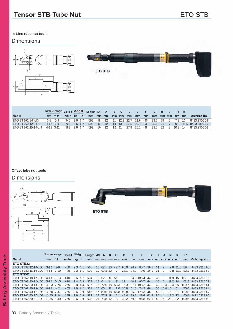
80 Battery Assembly Tools
Bat
tery
Ass
embl
y To
ols
DE
FF1
CR
H AF J G
A
B
R1
R1
R
Tensor STB Tube Nut ETO STB
Torque range Speed Weight Length A/F A B C D E F G H J R1 R Model Nm ft lb r/min kg lb mm mm mm mm mm mm mm mm mm mm mm mm mm Ordering No.ETO STB62-8-8-LI3 3-8 2-6 945 2.6 5.7 592 8 32 11 12.3 22.7 21.6 60 33.5 29 6 7.8 10 8433 2316 53ETO STB62-12-8-LI3 4-12 3-9 723 2.6 5.7 598 8 32 10 13 27.3 25.4 66 33.5 31 7 9.8 11.5 8433 2316 56ETO STB62-15-10-LI3 4-15 3-11 589 2.6 5.7 599 10 32 12 11 27.9 26.1 68 33.5 32 8 10.3 14 8433 2316 62
Torque range Speed Weight Length A/F A B C D E F G H J R1 R F1 Model Nm ft lb r/min kg lb mm mm mm mm mm mm mm mm mm mm mm mm mm mm Ordering No.ETO STB32ETO STB32-12-10-LO5 3-12 2-9 480 2.3 5.1 566 10 62 10 42.7 60.9 70.7 85.7 36.5 31 7 9.8 11.5 89 8433 2315 66ETO STB32-15-10-LO3 4-14 3-10 480 2.3 5.1 530 10 63.3 12 7 25.1 34.9 49.9 36.5 31 7 9.8 11.5 53.2 8433 2315 63ETO STB62ETO STB62-18-12-LO5 4-18 3-13 610 2.6 5.7 604 12 62 11 51 73 84.9 105.4 44 38 8 11.9 15 107 8433 2315 75ETO STB62-20-12-LO3 5-20 3-15 610 2.4 5.3 559 12 64 14 7 29 40.2 60.7 44 38 8 11.2 14 62.2 8433 2315 72ETO STB62-30-13-LO5 10-33 7-24 265 3.8 8.4 617 13 72.5 18 53.3 75.3 87.7 108.2 44 40 10.4 12.4 25 109.7 8433 2315 81ETO STB62-28-13-LO3 6-28 4-21 465 2.8 6.2 581 13 65 11 12.8 36.8 51.8 74.3 48 50 10.4 15 31 75.8 8433 2315 84ETO STB62-40-17-LO5 10-50 7-37 265 3.6 7.9 645 17 80.5 18 66.8 90.8 105.8 128.3 48 50 12 15 31 129.8 8433 2315 87ETO STB62-50-17-LO3 11-60 8-44 265 3.6 7.9 598 17 77.8 18 11.1 42.4 59.6 85.6 62.5 59 14 17.2 32 90.9 8433 2315 90ETO STB62-50-21-LO3 11-55 8-40 265 3.6 7.9 608 21 73.8 12 18 49.2 69.3 96.8 62.5 59 16 20.1 32 100.6 8433 2315 93
In-Line tube nut tools
Dimensions
Offset tube nut tools
Dimensions
Am_Batteryasstools.indd 80 2012-02-06 11:01:53
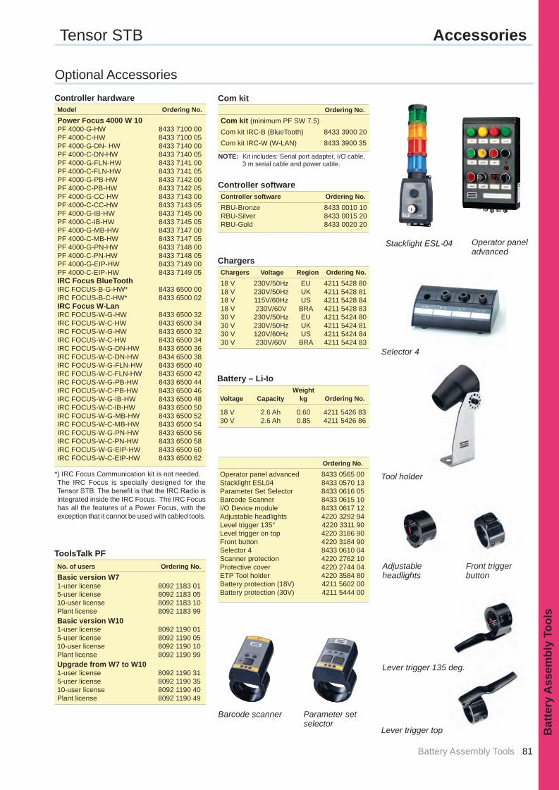
Battery Assembly Tools 81
Bat
tery
Ass
embl
y To
ols
Tensor STB Accessories
Optional Accessories
Controller softwareController software Ordering No.RBU-Bronze 8433 0010 10RBU-Silver 8433 0015 20RBU-Gold 8433 0020 20
Battery – Li-Io Weight Voltage Capacity kg Ordering No.
18 V 2.6 Ah 0.60 4211 5426 8330 V 2.6 Ah 0.85 4211 5426 86
ChargersChargers Voltage Region Ordering No.18 V 230V/50Hz EU 4211 5428 8018 V 230V/50Hz UK 4211 5428 8118 V 115V/60Hz US 4211 5428 8418 V 230V/60V BRA 4211 5428 8330 V 230V/50Hz EU 4211 5424 8030 V 230V/50Hz UK 4211 5424 8130 V 120V/60Hz US 4211 5424 8430 V 230V/60V BRA 4211 5424 83
Controller hardwareModel Ordering No.Power Focus 4000 W 10PF 4000-G-HW 8433 7100 00PF 4000-C-HW 8433 7100 05PF 4000-G-DN- HW 8433 7140 00PF 4000-C-DN-HW 8433 7140 05PF 4000-G-FLN-HW 8433 7141 00PF 4000-C-FLN-HW 8433 7141 05PF 4000-G-PB-HW 8433 7142 00PF 4000-C-PB-HW 8433 7142 05PF 4000-G-CC-HW 8433 7143 00PF 4000-C-CC-HW 8433 7143 05PF 4000-G-IB-HW 8433 7145 00PF 4000-C-IB-HW 8433 7145 05PF 4000-G-MB-HW 8433 7147 00PF 4000-C-MB-HW 8433 7147 05PF 4000-G-PN-HW 8433 7148 00PF 4000-C-PN-HW 8433 7148 05PF 4000-G-EIP-HW 8433 7149 00PF 4000-C-EIP-HW 8433 7149 05IRC Focus BlueToothIRC FOCUS-B-G-HW* 8433 6500 00IRC FOCUS-B-C-HW* 8433 6500 02IRC Focus W-LanIRC FOCUS-W-G-HW 8433 6500 32IRC FOCUS-W-C-HW 8433 6500 34IRC FOCUS-W-G-HW 8433 6500 32IRC FOCUS-W-C-HW 8433 6500 34IRC FOCUS-W-G-DN-HW 8433 6500 36IRC FOCUS-W-C-DN-HW 8434 6500 38IRC FOCUS-W-G-FLN-HW 8433 6500 40IRC FOCUS-W-C-FLN-HW 8433 6500 42IRC FOCUS-W-G-PB-HW 8433 6500 44IRC FOCUS-W-C-PB-HW 8433 6500 46IRC FOCUS-W-G-IB-HW 8433 6500 48IRC FOCUS-W-C-IB-HW 8433 6500 50IRC FOCUS-W-G-MB-HW 8433 6500 52IRC FOCUS-W-C-MB-HW 8433 6500 54IRC FOCUS-W-G-PN-HW 8433 6500 56IRC FOCUS-W-C-PN-HW 8433 6500 58IRC FOCUS-W-G-EIP-HW 8433 6500 60IRC FOCUS-W-C-EIP-HW 8433 6500 62
*) IRC Focus Communication kit is not needed.The IRC Focus is specially designed for the Tensor STB. The benefit is that the IRC Radio is integrated inside the IRC Focus. The IRC Focus has all the features of a Power Focus, with the exception that it cannot be used with cabled tools.
Ordering No.Operator panel advanced 8433 0565 00Stacklight ESL04 8433 0570 13Parameter Set Selector 8433 0616 05Barcode Scanner 8433 0615 10I/O Device module 8433 0617 12Adjustable headlights 4220 3292 94Level trigger 135° 4220 3311 90Level trigger on top 4220 3186 90Front button 4220 3184 90Selector 4 8433 0610 04Scanner protection 4220 2762 10Protective cover 4220 2744 04ETP Tool holder 4220 3584 80Battery protection (18V) 4211 5602 00Battery protection (30V) 4211 5444 00
Stacklight ESL-04 Operator panel advanced
Lever trigger top
Lever trigger 135 deg.
Parameter set selector
Barcode scanner
Adjustableheadlights
Selector 4
ToolsTalk PFNo. of users Ordering No.Basic version W71-user license 8092 1183 015-user license 8092 1183 0510-user license 8092 1183 10Plant license 8092 1183 99Basic version W101-user license 8092 1190 015-user license 8092 1190 0510-user license 8092 1190 10Plant license 8092 1190 99Upgrade from W7 to W101-user license 8092 1190 315-user license 8092 1190 3510-user license 8092 1190 40Plant license 8092 1190 49
Front triggerbutton
Tool holder
NOTE: Kit includes: Serial port adapter, I/O cable, 3 m serial cable and power cable.
Com kit Ordering No.Com kit (minimum PF SW 7.5) Com kit IRC-B (BlueTooth) 8433 3900 20Com kit IRC-W (W-LAN) 8433 3900 35
Am_Batteryasstools.indd 81 2012-03-06 09:09:18

Electric AssemblyTools and Systems
Contents PageIntroduction .......................................... 83Product safety...................................... 84
Screwdrivers 85EBL ...................................................... 86MicroTorque ......................................... 88Tensor DL ............................................ 92Tensor SL ............................................ 93Tensor STR.......................................... 94
Nutrunners 98Tensor DS .......................................... 100Tensor S ............................................ 106Tensor ST .......................................... 109Tensor STR.........................................117
Controllers and software 125DS/DL drive ....................................... 127Power Focus...................................... 128Programming software ...................... 130
Quality Integrated Fastening 131Station hardware ............................... 133Station software ................................. 135
Am_Electricscrewdrivers.indd 82 2012-02-06 11:06:41

83
Elec
tric
Ass
embl
y To
ols
and
Ass
embl
y Sy
stem
s
Electric Assembly Tools and Assembly Systems 83
Introduction – Electric Assembly Tools and Systems
Highest productivity with lowest life-cycle cost
Atlas Copco supplies a comprehensive range of high productivity assembly tools with intelligent controllers and a sharp focus on ergonomics. Our many product lines were developed to meet all your tightening needs and give you lowest life-cycle cost. Products range from low torque MicroTorque tools provid-ing 0.5 Ncm of torque, to high torque Tensor ST tools, offering up to 4,000 Nm.
EBL ScrewdriverLow voltage, brushless screwdriver for demanding applications, with shut-off clutch for high fastening precision, time after time.
MicroTorque Ultra low torque screw-driverUltra low torque intelligent screwdrivers that ensure joint integrity in high volume consumer applications and high value critical products.
Power Focus controllerThe Power Focus is the market-leading controller for handheld tools and has the capability to run fixtured tools. Power Fo-cus is a modular range of controllers with full flexibility and connectivity to fit your production infrastructure. The Power Focus 4000 controls tools in the Tensor S, ST, STB, DS, SL and ETX family. The Power Focus 4002 controls Tensor SL tools.
DS/DL controllerThe DS/DL system offers a quick and easy route to improved process monitor-ing in your assembly operations. With a range of alternative drives, you can choose the functionality best suited for your operations. The DS drive runs Ten-sor DS tools and exists as Box, Basic or Advanced version. The DL drive runs Tensor DL tools and is available as Basic or Advanced models.
Tensor ToolsThe Tensor tool range covers all assem-bly requirements for safety critical and quality critical applications.
Tensor SL: Safety-critical low torque tools for small screw applications. It offers compact screwdriver ergonomics with traceability and error proofing capability.
Tensor S: Tensor S is the well proven range for safety critical applications where traceability and error proofing ca-pability are required.
Tensor ST: The second generation of Tensor tools was developed with the focus on reducing tool weight and in-creasing productivity. Tensor ST has an internal bus connection for intelli-gent accessories such as a barcode reader and P-selector switch.
Tensor STR: The latest generation of Tensor tools where ergonomics and pro-ductivity are taken to a new level.
Tensor DS: Quality critical applications where demands on accuracy and ergo-nomics are high.
Tensor DL: Quality critical applications with high demands on quality assurance.
Tensor STB: The battery version of Ten-sor ST for safety critical applications.
Am_Electricscrewdrivers.indd 83 2012-02-06 11:06:46
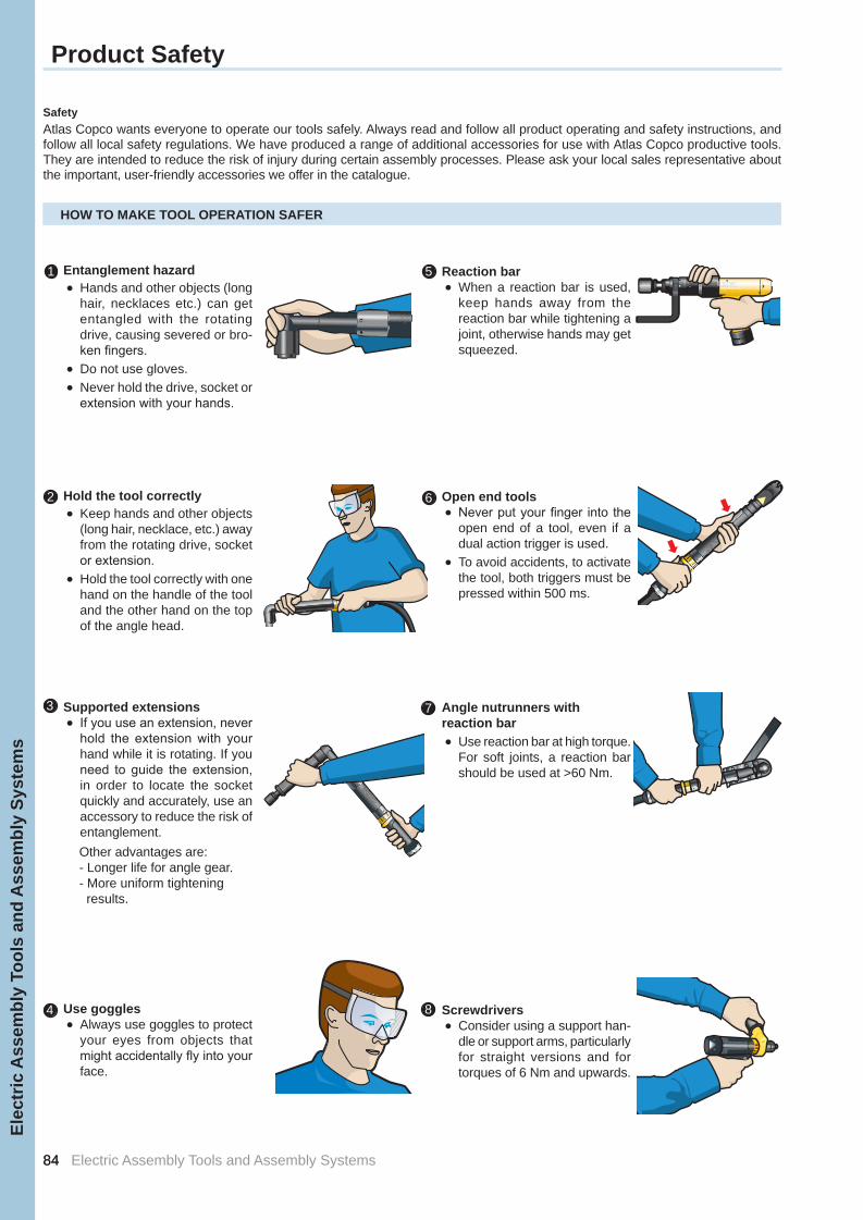
84
Elec
tric
Ass
embl
y To
ols
and
Ass
embl
y Sy
stem
s
84 Electric Assembly Tools and Assembly Systems
1
2
3
4
5
6
7
8
Reaction barl When a reaction bar is used,
keep hands away from the reaction bar while tightening a joint, otherwise hands may get squeezed.
Open end toolsl Never put your finger into the
open end of a tool, even if a dual action trigger is used.
l To avoid accidents, to activate the tool, both triggers must be pressed within 500 ms.
Angle nutrunners with reaction bar
l Use reaction bar at high torque. For soft joints, a reaction bar should be used at >60 Nm.
Screwdriversl Consider using a support han-
dle or support arms, particularly for straight versions and for torques of 6 Nm and upwards.
SafetyAtlas Copco wants everyone to operate our tools safely. Always read and follow all product operating and safety instructions, and follow all local safety regulations. We have produced a range of additional accessories for use with Atlas Copco productive tools. They are intended to reduce the risk of injury during certain assembly processes. Please ask your local sales representative about the important, user-friendly accessories we offer in the catalogue.
Product Safety
HOw TO MAkE TOOL OPERATIOn SAFER
Entanglement hazardl Hands and other objects (long
hair, necklaces etc.) can get entangled with the rotating drive, causing severed or bro-ken fingers.
l Do not use gloves.l Never hold the drive, socket or
extension with your hands.
Hold the tool correctlyl Keep hands and other objects
(long hair, necklace, etc.) away from the rotating drive, socket or extension.
l Hold the tool correctly with one hand on the handle of the tool and the other hand on the top of the angle head.
Supported extensionsl If you use an extension, never
hold the extension with your hand while it is rotating. If you need to guide the extension, in order to locate the socket quickly and accurately, use an accessory to reduce the risk of entanglement. Other advantages are:- Longer life for angle gear.- More uniform tightening results.
Use gogglesl Always use goggles to protect
your eyes from objects that might accidentally fly into your face.
Am_Electricscrewdrivers.indd 84 2012-02-06 11:06:51
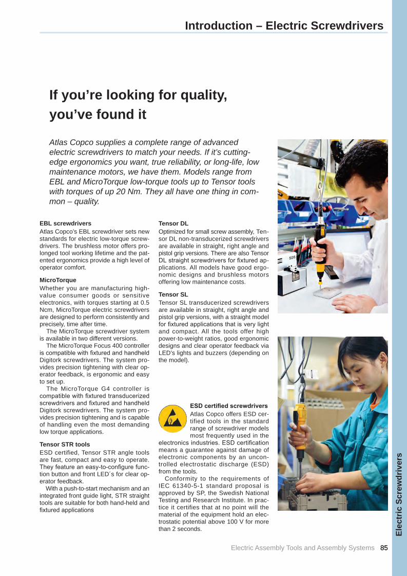
85
Elec
tric
Scr
ewdr
iver
s
Electric Assembly Tools and Assembly Systems 85
ESD certified screwdriversAtlas Copco offers ESD cer-tified tools in the standard range of screwdriver models most frequently used in the
electronics industries. ESD certification means a guarantee against damage of electronic components by an uncon-trolled electrostatic discharge (ESD) from the tools.
Conformity to the requirements of IEC 61340-5-1 standard proposal is approved by SP, the Swedish National Testing and Research Institute. In prac-tice it certifies that at no point will the material of the equipment hold an elec-trostatic potential above 100 V for more than 2 seconds.
Introduction – Electric Screwdrivers
If you’re looking for quality, you’ve found it
Atlas Copco supplies a complete range of advanced electric screwdrivers to match your needs. If it’s cutting-edge ergonomics you want, true reliability, or long-life, low maintenance motors, we have them. Models range from EBL and MicroTorque low-torque tools up to Tensor tools with torques of up 20 Nm. They all have one thing in com-mon – quality.
EBL screwdriversAtlas Copco’s EBL screwdriver sets new standards for electric low-torque screw-drivers. The brushless motor offers pro-longed tool working lifetime and the pat-ented ergonomics provide a high level of operator comfort.
MicroTorque Whether you are manufacturing high-value consumer goods or sensitive electronics, with torques starting at 0.5 Ncm, MicroTorque electric screwdrivers are designed to perform consistently and precisely, time after time.
The MicroTorque screwdriver system is available in two different versions.
The MicroTorque Focus 400 controller is compatible with fixtured and handheld Digitork screwdrivers. The system pro-vides precision tightening with clear op-erator feedback, is ergonomic and easy to set up.
The MicroTorque G4 controller is compatible with fixtured transducerized screwdrivers and fixtured and handheld Digitork screwdrivers. The system pro-vides precision tightening and is capable of handling even the most demanding low torque applications.
Tensor STR toolsESD certified, Tensor STR angle tools are fast, compact and easy to operate. They feature an easy-to-configure func-tion button and front LED´s for clear op-erator feedback.
With a push-to-start mechanism and an integrated front guide light, STR straight tools are suitable for both hand-held and fixtured applications
Tensor DL Optimized for small screw assembly, Ten-sor DL non-transducerized screwdrivers are available in straight, right angle and pistol grip versions. There are also Tensor DL straight screwdrivers for fixtured ap-plications. All models have good ergo-nomic designs and brushless motors offering low maintenance costs.
Tensor SLTensor SL transducerized screwdrivers are available in straight, right angle and pistol grip versions, with a straight model for fixtured applications that is very light and compact. All the tools offer high power-to-weight ratios, good ergonomic designs and clear operator feedback via LED’s lights and buzzers (depending on the model).
Am_Electricscrewdrivers.indd 85 2012-02-06 11:06:58
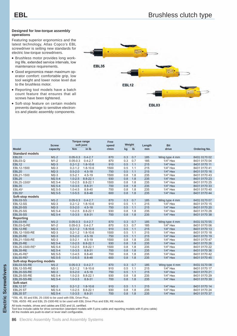
86
Elec
tric
Scr
ewdr
iver
s
86 Electric Assembly Tools and Assembly Systems
EBL Brushless clutch type
Torque range Free Screw soft joint speed weight Length BitModel capacity nm in lb r/min kg lb mm drive Or der ing no.Standard modelsEBL03 M1-2 0.05-0.3 0.4-2.7 870 0.3 0.7 185 Wing type 4 mm 8431 0170 02EBL03-Q M1-2 0.05-0.3 0.4-2.7 870 0.3 0.7 185 1/4" Hex 8431 0170 04EBL12 M2-3 0.2-1.2 1.8-10.6 910 0.5 1.1 215 1/4" Hex 8431 0170 11EBL12-1500 M2-3 0.2-1.2 1.8-10.6 1500 0.5 1.1 215 1/4" Hex 8431 0170 41EBL20 M2-3 0.5-2.0 4.5-18 750 0.5 1.1 215 1/4" Hex 8431 0170 16EBL21-1500 M2-3 0.5-2.1 4.5-19 1500 0.8 1.8 235 1/4" Hex 8431 0170 43EBL25 M2.5-4 1.0-2.5 8.8-22.1 930 0.8 1.8 235 1/4" Hex 8431 0170 23EBL25-1500a M2.5-4 1.0-2.5 8.8-22.1 1500 0.8 1.8 235 1/4" Hex 8431 0170 25EBL35 M2.5-4 1.0-3.5 8.8-31 700 0.8 1.8 235 1/4" Hex 8431 0170 33EBL45a M2.5-5 1.0-4.5 8.8-40 700 0.8 1.8 235 1/4" Hex 8431 0170 40EBL55a M2.5-5 1.0-5.5 8.8-48 600 0.8 1.8 235 1/4" Hex 8431 0170 44Soft-stop modelsEBL03-SS M1-2 0.05-0.3 0.4-2.7 870 0.3 0.7 185 Wing type 4 mm 8431 0170 07EBL12-SS M2-3 0.2-1.2 1.8-10.6 910 0.5 1.1 215 1/4" Hex 8431 0170 15EBL20-SS M2-3 0.5-2.0 4.5-18 750 0.5 1.1 215 1/4" Hex 8431 0170 20EBL25-SS M2.5-4 1.0-2.5 8.8-22.1 930 0.8 1.8 235 1/4" Hex 8431 0170 28EBL35-SS M2.5-4 1.0-3.5 8.8-31 700 0.8 1.8 235 1/4" Hex 8431 0170 38ReportingEBL03-RE M1-2 0.05-0.3 0.4-2.7 870 0.3 0.7 185 Wing type 4 mm 8431 0170 55EBL03-Q-RE M1-2 0.05-0.3 0.4-2.7 870 0.3 0.7 185 1/4" Hex 8431 0170 06EBL12-RE M2-3 0.2-1.2 1.8-10.6 910 0.5 1.1 215 1/4" Hex 8431 0170 13EBL12-1500-RE M2-3 0.2-1.2 1.8-10.6 1500 0.5 1.1 215 1/4" Hex 8431 0170 18EBL20-RE M2-3 0.5-2.0 4.5-18 750 0.5 1.1 215 1/4" Hex 8431 0170 19EBL21-1500-RE M2-3 0.5-2.1 4.5-19 1500 0.8 1.8 235 1/4" Hex 8431 0170 47EBL25-RE M2.5-4 1.0-2.5 8.8-22.1 930 0.8 1.8 235 1/4" Hex 8431 0170 26EBL25-1500-REb M2.5-4 1.0-2.5 8.8-22.1 1500 0.8 1.8 235 1/4" Hex 8431 0170 22EBL35-RE M2.5-4 1.0-3.5 8.8-31 700 0.8 1.8 235 1/4" Hex 8431 0170 36EBL45-REb M2.5-5 1.0-4.5 8.8-40 700 0.8 1.8 235 1/4" Hex 8431 0170 42EBL55-REb M2.5-5 1.0-5.5 8.8-48 600 0.8 1.8 235 1/4" Hex 8431 0170 45Soft-stop Reporting modelsEBL03-SS-RE M1-2 0.05-0.3 0.4-2.7 870 0.3 0.7 185 Wing type 4 mm 8431 0170 08EBL12-SS-RE M2-3 0.2-1.2 1.8-10.6 910 0.5 1.1 215 1/4" Hex 8431 0170 17EBL20-SS-RE M2-3 0.5-2.0 4.5-18 750 0.5 1.1 215 1/4" Hex 8431 0170 21EBL25-SS-RE M2.5-4 1.0-2.5 8.8-22.1 930 0.8 1.8 235 1/4" Hex 8431 0170 29EBL35-SS-RE M2.5-4 1.0-3.5 8.8-31 700 0.8 1.8 235 1/4" Hex 8431 0170 39Soft-start EBL12 ST M2-3 0.2-1.2 1.8-10.6 910 0.5 1.1 215 1/4" Hex 8431 0170 14EBL25 ST M2.5-4 1.0-2.5 8.8-22.1 930 0.8 1.8 235 1/4" Hex 8431 0170 24EBL35 ST M2.5-4 1.0-3.5 8.8-31 700 0.8 1.8 235 1/4" Hex 8431 0170 37
Designed for low-torque assembly operationsFeaturing superior ergonomics and the latest technology, Atlas Copco’s EBL screwdriver is setting new standards for electric low-torque screwdrivers.l Brushless motor provides long work-
ing life, extended service intervals, low maintenance requirements.
l Good ergonomics mean maximum op-erator comfort: comfortable grip, low tool weight and lower noise level due to the brushless motor.
l Reporting tool models have a batch count feature that ensures that all screws have been tightened.
l Soft-stop feature on certain models prevents damage to sensitive electron-ics and plastic assembly components.
a EBL 45, 55 and EBL 25-1500 to be used with EBL Drive Plus.b EBL 45/55 -RE and EBL 25-1500-RE to be used with EBL Drive Plus and EBL RE module.All tools models, drives and cables are ESD and UL certifi ed.Tool box include cable for drive connection (standard models with 5 pins cable and reporting models with 6 pins cable)All the models are push-to-start or lever start confi gurable.
Am_Electricscrewdrivers.indd 86 2012-02-06 11:06:59
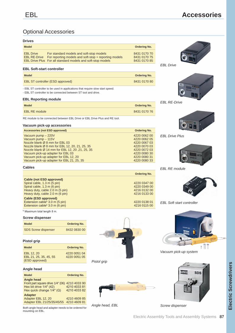
87
Elec
tric
Scr
ewdr
iver
s
Electric Assembly Tools and Assembly Systems 87
EBL Accessories
Optional Accessories
Model Ordering no.
EBL Drive For standard models and soft-stop models 8431 0170 70EBL RE-Drive For reporting models and soft-stop + reporting models 8431 0170 75EBL Drive Plus For all standard models and soft-stop models 8431 0170 85
Model Ordering no.
EBL ST controller (ESD approved) 8431 0170 80
- EBL ST controller to be used in applications that require slow start speed.- EBL ST controller to be connected between ST tool and drive.
Accessories (not ESD approved) Ordering no.
Vacuum pump – 220V 4220 0062 00Vacuum pump – 115V 4220 0062 05Nozzle blank Ø 8 mm for EBL 03 4220 0067 03Nozzle blank Ø 8 mm for EBL 12, 20, 21, 25, 35 4220 0070 03Nozzle blank Ø 14 mm for EBL 12, 20 ,21, 25, 35 4220 0072 03Vacuum pick-up adapter for EBL 03 4220 0080 30Vacuum pick-up adapter for EBL 12, 20 4220 0080 31Vacuum pick-up adapter for EBL 21, 25, 35 4220 0080 33
Vacuum pick-up accessories
Cables Or der ing no.
Cable (not ESD approved)Spiral cable, 1.3 m (5 pin) 4220 0347 00Spiral cable, 1.3 m (6 pin) 4220 0349 00Heavy duty, cable 2.0 m (5 pin) 4216 0132 00Heavy duty, cable 2.0 m (6 pin) 4216 0133 00Cable (ESD approved)Extension cableb 3.0 m (5 pin) 4220 0138 01Extension cableb 3.0 m (6 pin) 4216 0115 00
Pistol grip
Angle headModel Ordering no.Angle head Front part square drive 1/4" (06) 4210 4033 90Hex bit drive 1/4" (42) 4210 4033 81Hex quick change 1/4" (Q) 4210 4033 82Adapter Adapter EBL 12, 20 4210 4609 85Adapter EBL 21/25/35/45/55 4210 4609 81
Model Ordering no.
EBL 12, 20 4220 0051 04EBL 21, 25, 35, 45, 55 4220 0051 05(ESD approved)
b Maximum total length 8 m.
EBL Drive
EBL RE-Drive
EBL Soft start controller
Pistol grip
Vacuum pick-up system
EBL Drive Plus
Angle head, EBL
Drives
EBL Soft-start controller
Screw dispenserModel Ordering no.
SDS Screw dispenser 8432 0830 00
Model Ordering no.
EBL RE module 8431 0170 76
EBL Reporting module
RE module to be connected between EBL Drive or EBL Drive Plus and RE tool.
Screw dispenserBoth angle head and adapter needs to be ordered for mounting on EBL.
EBL RE module
Am_Electricscrewdrivers.indd 87 2012-02-06 11:07:14
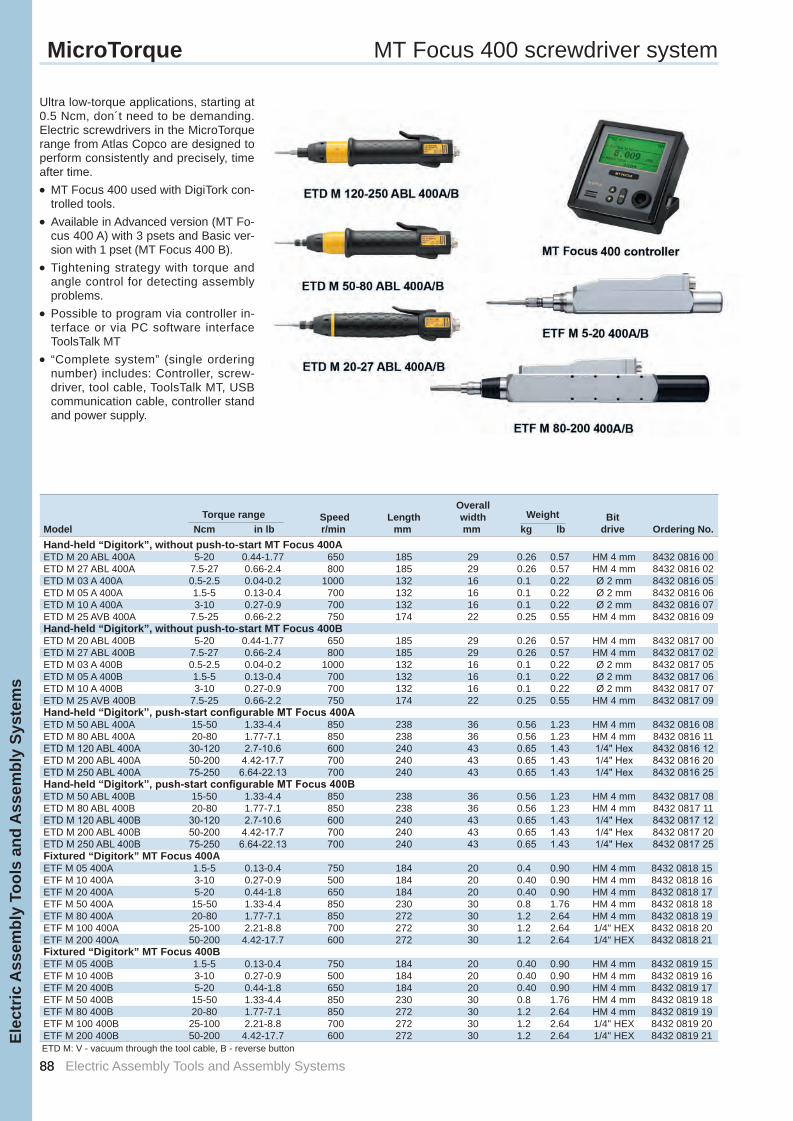
88
Elec
tric
Ass
embl
y To
ols
and
Ass
embl
y Sy
stem
s
88 Electric Assembly Tools and Assembly Systems
Overall Torque range Speed Length width weight BitModel ncm in lb r/min mm mm kg lb drive Ordering no.Hand-held “Digitork”, without push-to-start MT Focus 400AETD M 20 ABL 400A 5-20 0.44-1.77 650 185 29 0.26 0.57 HM 4 mm 8432 0816 00ETD M 27 ABL 400A 7.5-27 0.66-2.4 800 185 29 0.26 0.57 HM 4 mm 8432 0816 02ETD M 03 A 400A 0.5-2.5 0.04-0.2 1000 132 16 0.1 0.22 Ø 2 mm 8432 0816 05ETD M 05 A 400A 1.5-5 0.13-0.4 700 132 16 0.1 0.22 Ø 2 mm 8432 0816 06ETD M 10 A 400A 3-10 0.27-0.9 700 132 16 0.1 0.22 Ø 2 mm 8432 0816 07ETD M 25 AVB 400A 7.5-25 0.66-2.2 750 174 22 0.25 0.55 HM 4 mm 8432 0816 09Hand-held “Digitork”, without push-to-start MT Focus 400BETD M 20 ABL 400B 5-20 0.44-1.77 650 185 29 0.26 0.57 HM 4 mm 8432 0817 00ETD M 27 ABL 400B 7.5-27 0.66-2.4 800 185 29 0.26 0.57 HM 4 mm 8432 0817 02ETD M 03 A 400B 0.5-2.5 0.04-0.2 1000 132 16 0.1 0.22 Ø 2 mm 8432 0817 05ETD M 05 A 400B 1.5-5 0.13-0.4 700 132 16 0.1 0.22 Ø 2 mm 8432 0817 06ETD M 10 A 400B 3-10 0.27-0.9 700 132 16 0.1 0.22 Ø 2 mm 8432 0817 07ETD M 25 AVB 400B 7.5-25 0.66-2.2 750 174 22 0.25 0.55 HM 4 mm 8432 0817 09Hand-held “Digitork”, push-start confi gurable MT Focus 400AETD M 50 ABL 400A 15-50 1.33-4.4 850 238 36 0.56 1.23 HM 4 mm 8432 0816 08ETD M 80 ABL 400A 20-80 1.77-7.1 850 238 36 0.56 1.23 HM 4 mm 8432 0816 11ETD M 120 ABL 400A 30-120 2.7-10.6 600 240 43 0.65 1.43 1/4" Hex 8432 0816 12ETD M 200 ABL 400A 50-200 4.42-17.7 700 240 43 0.65 1.43 1/4" Hex 8432 0816 20ETD M 250 ABL 400A 75-250 6.64-22.13 700 240 43 0.65 1.43 1/4" Hex 8432 0816 25Hand-held “Digitork”, push-start confi gurable MT Focus 400BETD M 50 ABL 400B 15-50 1.33-4.4 850 238 36 0.56 1.23 HM 4 mm 8432 0817 08ETD M 80 ABL 400B 20-80 1.77-7.1 850 238 36 0.56 1.23 HM 4 mm 8432 0817 11ETD M 120 ABL 400B 30-120 2.7-10.6 600 240 43 0.65 1.43 1/4" Hex 8432 0817 12ETD M 200 ABL 400B 50-200 4.42-17.7 700 240 43 0.65 1.43 1/4" Hex 8432 0817 20ETD M 250 ABL 400B 75-250 6.64-22.13 700 240 43 0.65 1.43 1/4" Hex 8432 0817 25Fixtured “Digitork” MT Focus 400AETF M 05 400A 1.5-5 0.13-0.4 750 184 20 0.4 0.90 HM 4 mm 8432 0818 15ETF M 10 400A 3-10 0.27-0.9 500 184 20 0.40 0.90 HM 4 mm 8432 0818 16ETF M 20 400A 5-20 0.44-1.8 650 184 20 0.40 0.90 HM 4 mm 8432 0818 17ETF M 50 400A 15-50 1.33-4.4 850 230 30 0.8 1.76 HM 4 mm 8432 0818 18ETF M 80 400A 20-80 1.77-7.1 850 272 30 1.2 2.64 HM 4 mm 8432 0818 19ETF M 100 400A 25-100 2.21-8.8 700 272 30 1.2 2.64 1/4" HEX 8432 0818 20ETF M 200 400A 50-200 4.42-17.7 600 272 30 1.2 2.64 1/4" HEX 8432 0818 21Fixtured “Digitork” MT Focus 400BETF M 05 400B 1.5-5 0.13-0.4 750 184 20 0.40 0.90 HM 4 mm 8432 0819 15ETF M 10 400B 3-10 0.27-0.9 500 184 20 0.40 0.90 HM 4 mm 8432 0819 16ETF M 20 400B 5-20 0.44-1.8 650 184 20 0.40 0.90 HM 4 mm 8432 0819 17ETF M 50 400B 15-50 1.33-4.4 850 230 30 0.8 1.76 HM 4 mm 8432 0819 18ETF M 80 400B 20-80 1.77-7.1 850 272 30 1.2 2.64 HM 4 mm 8432 0819 19ETF M 100 400B 25-100 2.21-8.8 700 272 30 1.2 2.64 1/4" HEX 8432 0819 20ETF M 200 400B 50-200 4.42-17.7 600 272 30 1.2 2.64 1/4" HEX 8432 0819 21
MicroTorque MT Focus 400 screwdriver system
Ultra low-torque applications, starting at 0.5 Ncm, don´t need to be demanding. Electric screwdrivers in the MicroTorque range from Atlas Copco are designed to perform consistently and precisely, time after time.l MT Focus 400 used with DigiTork con-
trolled tools.l Available in Advanced version (MT Fo-
cus 400 A) with 3 psets and Basic ver-sion with 1 pset (MT Focus 400 B).
l Tightening strategy with torque and angle control for detecting assembly problems.
l Possible to program via controller in-terface or via PC software interface ToolsTalk MT
l “Complete system” (single ordering number) includes: Controller, screw-driver, tool cable, ToolsTalk MT, USB communication cable, controller stand and power supply.
ETD M: V - vacuum through the tool cable, B - reverse button
Am_Electricscrewdrivers.indd 88 2012-02-06 11:07:15
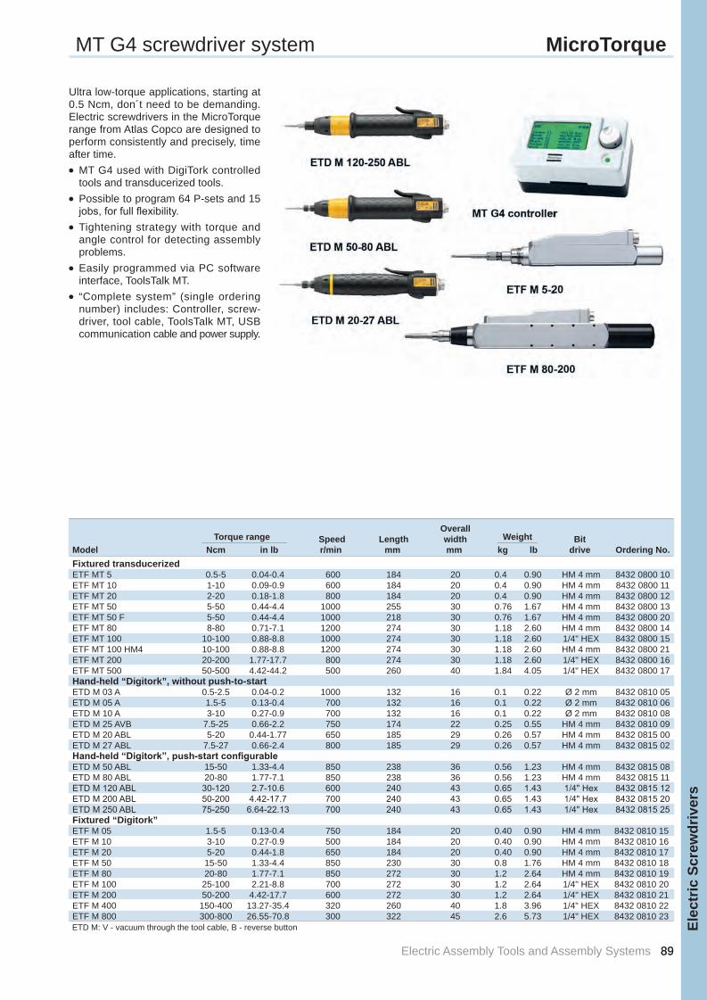
89
Elec
tric
Scr
ewdr
iver
s
Electric Assembly Tools and Assembly Systems 89
MT G4 screwdriver system MicroTorque
Overall Torque range Speed Length width weight BitModel ncm in lb r/min mm mm kg lb drive Ordering no.Fixtured transducerizedETF MT 5 0.5-5 0.04-0.4 600 184 20 0.4 0.90 HM 4 mm 8432 0800 10ETF MT 10 1-10 0.09-0.9 600 184 20 0.4 0.90 HM 4 mm 8432 0800 11ETF MT 20 2-20 0.18-1.8 800 184 20 0.4 0.90 HM 4 mm 8432 0800 12ETF MT 50 5-50 0.44-4.4 1000 255 30 0.76 1.67 HM 4 mm 8432 0800 13ETF MT 50 F 5-50 0.44-4.4 1000 218 30 0.76 1.67 HM 4 mm 8432 0800 20ETF MT 80 8-80 0.71-7.1 1200 274 30 1.18 2.60 HM 4 mm 8432 0800 14ETF MT 100 10-100 0.88-8.8 1000 274 30 1.18 2.60 1/4" HEX 8432 0800 15ETF MT 100 HM4 10-100 0.88-8.8 1200 274 30 1.18 2.60 HM 4 mm 8432 0800 21ETF MT 200 20-200 1.77-17.7 800 274 30 1.18 2.60 1/4" HEX 8432 0800 16ETF MT 500 50-500 4.42-44.2 500 260 40 1.84 4.05 1/4" HEX 8432 0800 17Hand-held “Digitork”, without push-to-start ETD M 03 A 0.5-2.5 0.04-0.2 1000 132 16 0.1 0.22 Ø 2 mm 8432 0810 05ETD M 05 A 1.5-5 0.13-0.4 700 132 16 0.1 0.22 Ø 2 mm 8432 0810 06ETD M 10 A 3-10 0.27-0.9 700 132 16 0.1 0.22 Ø 2 mm 8432 0810 08ETD M 25 AVB 7.5-25 0.66-2.2 750 174 22 0.25 0.55 HM 4 mm 8432 0810 09ETD M 20 ABL 5-20 0.44-1.77 650 185 29 0.26 0.57 HM 4 mm 8432 0815 00ETD M 27 ABL 7.5-27 0.66-2.4 800 185 29 0.26 0.57 HM 4 mm 8432 0815 02Hand-held “Digitork”, push-start confi gurableETD M 50 ABL 15-50 1.33-4.4 850 238 36 0.56 1.23 HM 4 mm 8432 0815 08ETD M 80 ABL 20-80 1.77-7.1 850 238 36 0.56 1.23 HM 4 mm 8432 0815 11ETD M 120 ABL 30-120 2.7-10.6 600 240 43 0.65 1.43 1/4" Hex 8432 0815 12ETD M 200 ABL 50-200 4.42-17.7 700 240 43 0.65 1.43 1/4" Hex 8432 0815 20ETD M 250 ABL 75-250 6.64-22.13 700 240 43 0.65 1.43 1/4" Hex 8432 0815 25Fixtured “Digitork”ETF M 05 1.5-5 0.13-0.4 750 184 20 0.40 0.90 HM 4 mm 8432 0810 15ETF M 10 3-10 0.27-0.9 500 184 20 0.40 0.90 HM 4 mm 8432 0810 16ETF M 20 5-20 0.44-1.8 650 184 20 0.40 0.90 HM 4 mm 8432 0810 17ETF M 50 15-50 1.33-4.4 850 230 30 0.8 1.76 HM 4 mm 8432 0810 18ETF M 80 20-80 1.77-7.1 850 272 30 1.2 2.64 HM 4 mm 8432 0810 19ETF M 100 25-100 2.21-8.8 700 272 30 1.2 2.64 1/4" HEX 8432 0810 20ETF M 200 50-200 4.42-17.7 600 272 30 1.2 2.64 1/4" HEX 8432 0810 21ETF M 400 150-400 13.27-35.4 320 260 40 1.8 3.96 1/4" HEX 8432 0810 22ETF M 800 300-800 26.55-70.8 300 322 45 2.6 5.73 1/4" HEX 8432 0810 23
Ultra low-torque applications, starting at 0.5 Ncm, don´t need to be demanding. Electric screwdrivers in the MicroTorque range from Atlas Copco are designed to perform consistently and precisely, time after time.l MT G4 used with DigiTork controlled
tools and transducerized tools.l Possible to program 64 P-sets and 15
jobs, for full fl exibility.l Tightening strategy with torque and
angle control for detecting assembly problems.
l Easily programmed via PC software interface, ToolsTalk MT.
l “Complete system” (single ordering number) includes: Controller, screw-driver, tool cable, ToolsTalk MT, USB communication cable and power supply.
ETD M: V - vacuum through the tool cable, B - reverse button
Am_Electricscrewdrivers.indd 89 2012-02-06 11:07:15
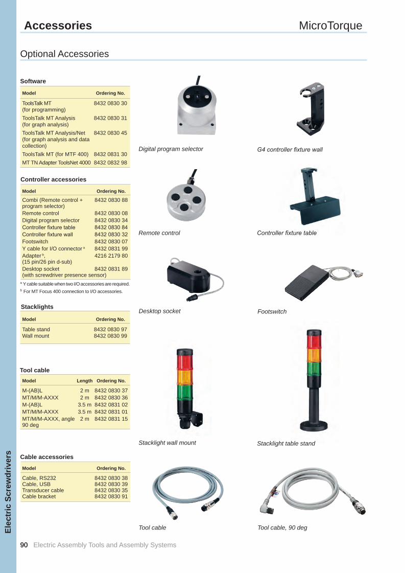
90
Elec
tric
Scr
ewdr
iver
s
90 Electric Assembly Tools and Assembly Systems
Accessories MicroTorque
Remote control
Digital program selector
Controller accessories
Model Ordering no.
Combi (Remote control + 8432 0830 88program selector) Remote control 8432 0830 08Digital program selector 8432 0830 34Controller fixture table 8432 0830 84Controller fixture wall 8432 0830 32Footswitch 8432 0830 07Y cable for I/O connector a 8432 0831 99Adapter b, 4216 2179 80(15 pin/26 pin d-sub)Desktop socket 8432 0831 89(with screwdriver presence sensor)
Tool cable
Tool cable Model Length Ordering no.
M-(AB)L 2 m 8432 0830 37MT/M/M-AXXX 2 m 8432 0830 36M-(AB)L 3.5 m 8432 0831 02MT/M/M-AXXX 3.5 m 8432 0831 01MT/M/M-AXXX, angle 2 m 8432 0831 1590 deg
Cable accessories
Model Ordering no.
Cable, RS232 8432 0830 38Cable, USB 8432 0830 39Transducer cable 8432 0830 35Cable bracket 8432 0830 91
G4 controller fixture wall
Footswitch
Controller fixture table
Desktop socket
a Y cable suitable when two I/O accessories are required.b For MT Focus 400 connection to I/O accessories.
Optional Accessories
Software
Model Ordering no.
ToolsTalk MT 8432 0830 30(for programming)ToolsTalk MT Analysis 8432 0830 31(for graph analysis) ToolsTalk MT Analysis/Net 8432 0830 45(for graph analysis and datacollection)ToolsTalk MT (for MTF 400) 8432 0831 30MT TN Adapter ToolsNet 4000 8432 0832 98
Stacklights
Model Ordering no.
Table stand 8432 0830 97Wall mount 8432 0830 99
Stacklight wall mount Stacklight table stand
Tool cable, 90 deg
Am_Electricscrewdrivers.indd 90 2012-02-06 11:07:33
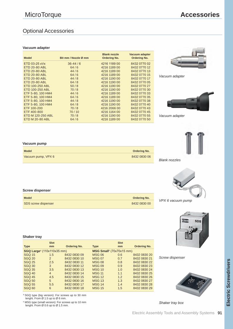
91
Elec
tric
Scr
ewdr
iver
s
Electric Assembly Tools and Assembly Systems 91
MicroTorque Accessories
Blank nozzle Vacuum adapterModel Bit mm / nozzle Ø mm Ordering no. Ordering no.
ETD 03-25 xVx 36-44 / 6 4216 1189 00 8432 0770 02ETD 20-80 ABL 64 / 6 4216 1189 00 8432 0770 12ETD 20-80 ABL 44 / 6 4216 1189 00 8432 0770 13ETD 20-80 ABL 64 / 6 4216 1189 00 8432 0770 15ETD 20-80 ABL 44 / 8 4216 1190 00 8432 0770 17ETD 20-80 ABL 64 / 8 4216 1190 00 8432 0770 05ETD 100-250 ABL 50 / 8 4216 1190 00 8432 0770 27ETD 100-250 ABL 70 / 8 4216 1190 00 8432 0770 30ETF 5-80, 100 HM4 44 / 6 4216 1189 00 8432 0770 33ETF 5-80, 100 HM4 64 / 6 4216 1189 00 8432 0770 35ETF 5-80, 100 HM4 44 / 8 4216 1190 00 8432 0770 38ETF 5-80, 100 HM4 64 / 8 4216 1190 00 8432 0770 40ETF 100-200 70 / 8 4216 2066 00 8432 0770 43ETF 400-800 70 / 10 4216 1164 00 8432 0770 45ETD M 120-250 ABL 70 / 8 4216 1190 00 8432 0770 55ETD M 20-80 ABL 64 / 6 4216 1189 00 8432 0770 50
Vacuum adapter
Vacuum pump
Model Ordering no.
Vacuum pump, VPX 6 8432 0830 06
Shaker tray Slot Type mm Ordering no.
SGQ Largea (110x110x35 mm)SGQ 15 1.5 8432 0830 09SGQ 20 2 8432 0830 10SGQ 25 2.5 8432 0830 11SGQ 30 3 8432 0830 12SGQ 35 3.5 8432 0830 13SGQ 40 4 8432 0830 14SGQ 45 4.5 8432 0830 15SGQ 50 5 8432 0830 16SGQ 55 5.5 8432 0830 17SGQ 60 6 8432 0830 18
a SGQ type (big version): For screws up to 30 mm lenght. From Ø 1.5 up to Ø 6 mm.
b MSG type (small version): For screws up to 10 mm lenght. From Ø 0.6 up to Ø 1.5 mm.
Slot Type mm Ordering no.
MSG Smallb (70x70x15 mm)MSG 06 0.6 8432 0830 20MSG 07 0.7 8432 0830 21MSG 08 0.8 8432 0830 22MSG 09 0.9 8432 0830 23MSG 10 1.0 8432 0830 24MSG 11 1.1 8432 0830 25MSG 12 1.2 8432 0830 26MSG 13 1.3 8432 0830 27MSG 14 1.4 8432 0830 28MSG 15 1.5 8432 0830 29
Vacuum adapter
Blank nozzles
VPX 6 vacuum pump
Shaker tray box
Optional Accessories
Screw dispenser
Model Ordering no.
SDS screw dispenser 8432 0830 00
Screw dispenser
Vacuum adapter
Am_Electricscrewdrivers.indd 91 2012-02-06 11:07:44
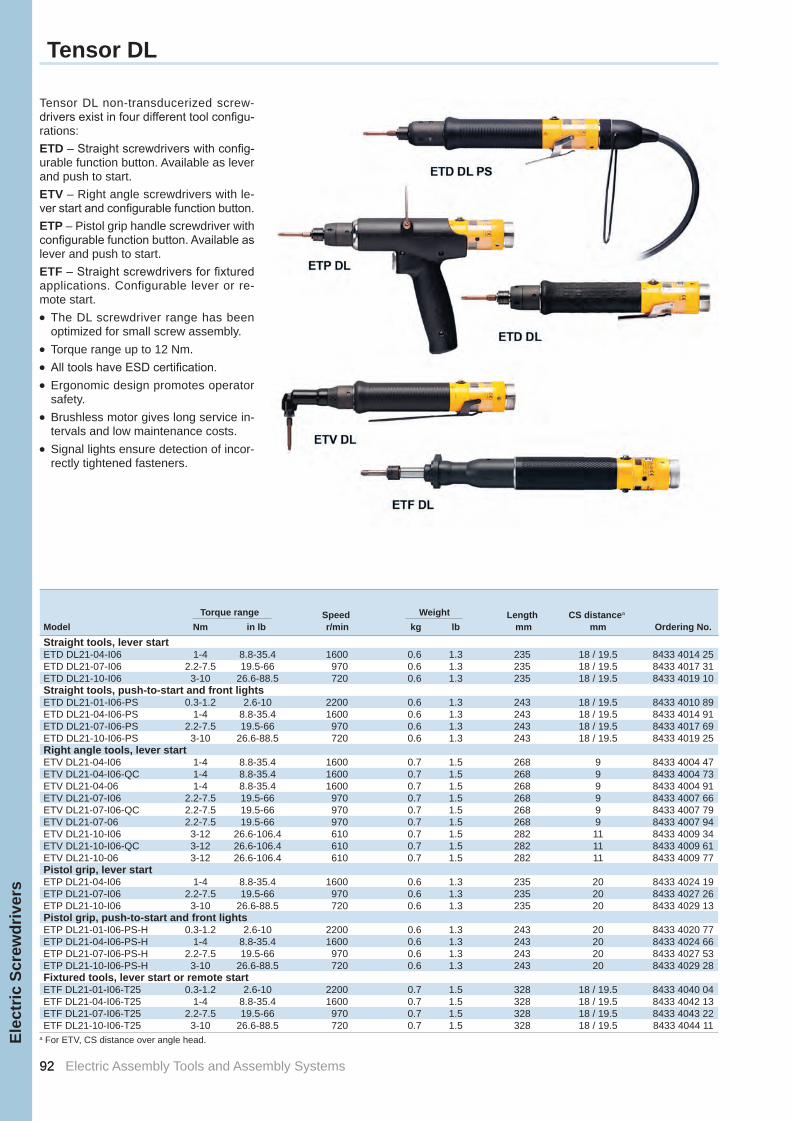
92
Elec
tric
Scr
ewdr
iver
s
92 Electric Assembly Tools and Assembly Systems
Tensor DL
Torque range Speed weight Length CS distancea Model nm in lb r/min kg lb mm mm Ordering no.Straight tools, lever startETD DL21-04-I06 1-4 8.8-35.4 1600 0.6 1.3 235 18 / 19.5 8433 4014 25ETD DL21-07-I06 2.2-7.5 19.5-66 970 0.6 1.3 235 18 / 19.5 8433 4017 31ETD DL21-10-I06 3-10 26.6-88.5 720 0.6 1.3 235 18 / 19.5 8433 4019 10Straight tools, push-to-start and front lightsETD DL21-01-I06-PS 0.3-1.2 2.6-10 2200 0.6 1.3 243 18 / 19.5 8433 4010 89ETD DL21-04-I06-PS 1-4 8.8-35.4 1600 0.6 1.3 243 18 / 19.5 8433 4014 91ETD DL21-07-I06-PS 2.2-7.5 19.5-66 970 0.6 1.3 243 18 / 19.5 8433 4017 69ETD DL21-10-I06-PS 3-10 26.6-88.5 720 0.6 1.3 243 18 / 19.5 8433 4019 25Right angle tools, lever startETV DL21-04-I06 1-4 8.8-35.4 1600 0.7 1.5 268 9 8433 4004 47ETV DL21-04-I06-QC 1-4 8.8-35.4 1600 0.7 1.5 268 9 8433 4004 73ETV DL21-04-06 1-4 8.8-35.4 1600 0.7 1.5 268 9 8433 4004 91ETV DL21-07-I06 2.2-7.5 19.5-66 970 0.7 1.5 268 9 8433 4007 66ETV DL21-07-I06-QC 2.2-7.5 19.5-66 970 0.7 1.5 268 9 8433 4007 79ETV DL21-07-06 2.2-7.5 19.5-66 970 0.7 1.5 268 9 8433 4007 94ETV DL21-10-I06 3-12 26.6-106.4 610 0.7 1.5 282 11 8433 4009 34ETV DL21-10-I06-QC 3-12 26.6-106.4 610 0.7 1.5 282 11 8433 4009 61ETV DL21-10-06 3-12 26.6-106.4 610 0.7 1.5 282 11 8433 4009 77Pistol grip, lever startETP DL21-04-I06 1-4 8.8-35.4 1600 0.6 1.3 235 20 8433 4024 19ETP DL21-07-I06 2.2-7.5 19.5-66 970 0.6 1.3 235 20 8433 4027 26ETP DL21-10-I06 3-10 26.6-88.5 720 0.6 1.3 235 20 8433 4029 13Pistol grip, push-to-start and front lightsETP DL21-01-I06-PS-H 0.3-1.2 2.6-10 2200 0.6 1.3 243 20 8433 4020 77ETP DL21-04-I06-PS-H 1-4 8.8-35.4 1600 0.6 1.3 243 20 8433 4024 66ETP DL21-07-I06-PS-H 2.2-7.5 19.5-66 970 0.6 1.3 243 20 8433 4027 53ETP DL21-10-I06-PS-H 3-10 26.6-88.5 720 0.6 1.3 243 20 8433 4029 28Fixtured tools, lever start or remote startETF DL21-01-I06-T25 0.3-1.2 2.6-10 2200 0.7 1.5 328 18 / 19.5 8433 4040 04ETF DL21-04-I06-T25 1-4 8.8-35.4 1600 0.7 1.5 328 18 / 19.5 8433 4042 13ETF DL21-07-I06-T25 2.2-7.5 19.5-66 970 0.7 1.5 328 18 / 19.5 8433 4043 22ETF DL21-10-I06-T25 3-10 26.6-88.5 720 0.7 1.5 328 18 / 19.5 8433 4044 11
Tensor DL non-transducerized screw-drivers exist in four different tool confi gu-rations:ETD – Straight screwdrivers with confi g-urable function button. Available as lever and push to start.ETV – Right angle screwdrivers with le-ver start and confi gurable function button.ETP – Pistol grip handle screwdriver with confi gurable function button. Available as lever and push to start.ETF – Straight screwdrivers for fi xtured applications. Configurable lever or re-mote start.l The DL screwdriver range has been
optimized for small screw assembly.l Torque range up to 12 Nm.l All tools have ESD certifi cation.l Ergonomic design promotes operator
safety.l Brushless motor gives long service in-
tervals and low maintenance costs.l Signal lights ensure detection of incor-
rectly tightened fasteners.
a For ETV, CS distance over angle head.
Am_Electricscrewdrivers.indd 92 2012-02-06 11:07:45
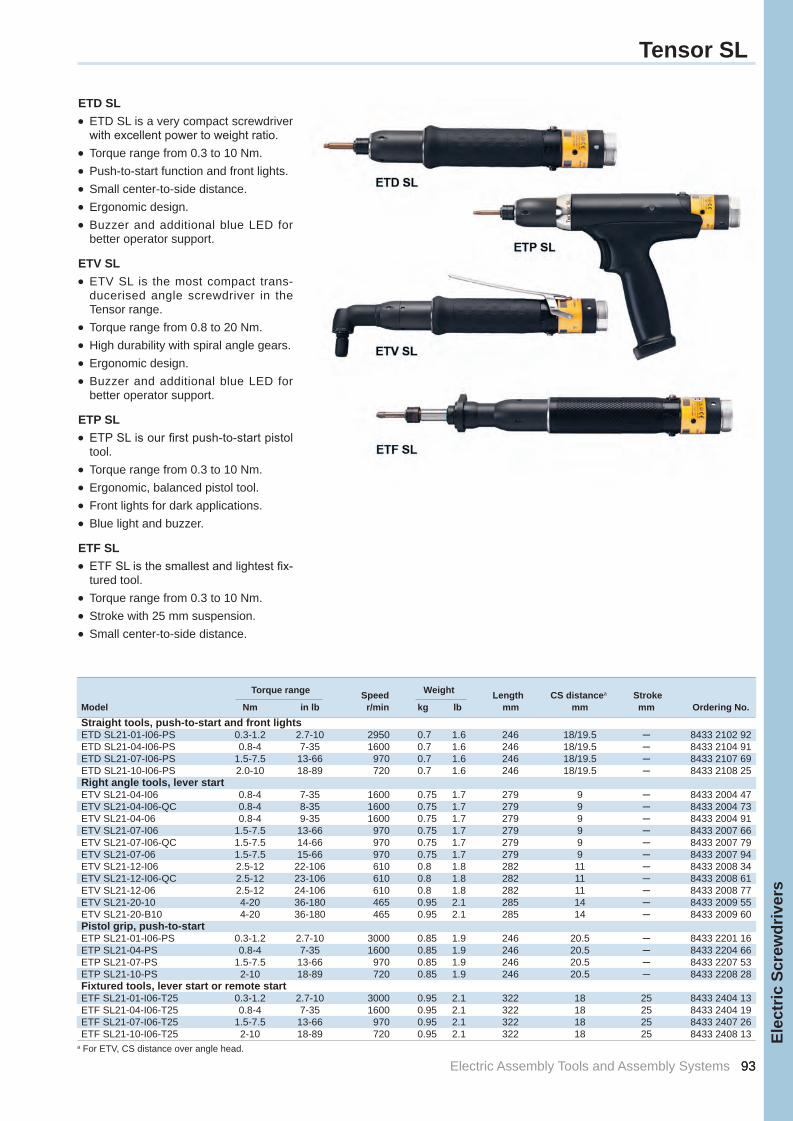
93
Elec
tric
Scr
ewdr
iver
s
Electric Assembly Tools and Assembly Systems 93
Torque range Speed weight Length CS distancea Stroke Model nm in lb r/min kg lb mm mm mm Ordering no.Straight tools, push-to-start and front lightsETD SL21-01-I06-PS 0.3-1.2 2.7-10 2950 0.7 1.6 246 18/19.5 ─ 8433 2102 92ETD SL21-04-I06-PS 0.8-4 7-35 1600 0.7 1.6 246 18/19.5 ─ 8433 2104 91ETD SL21-07-I06-PS 1.5-7.5 13-66 970 0.7 1.6 246 18/19.5 ─ 8433 2107 69ETD SL21-10-I06-PS 2.0-10 18-89 720 0.7 1.6 246 18/19.5 ─ 8433 2108 25Right angle tools, lever startETV SL21-04-I06 0.8-4 7-35 1600 0.75 1.7 279 9 ─ 8433 2004 47ETV SL21-04-I06-QC 0.8-4 8-35 1600 0.75 1.7 279 9 ─ 8433 2004 73ETV SL21-04-06 0.8-4 9-35 1600 0.75 1.7 279 9 ─ 8433 2004 91ETV SL21-07-I06 1.5-7.5 13-66 970 0.75 1.7 279 9 ─ 8433 2007 66ETV SL21-07-I06-QC 1.5-7.5 14-66 970 0.75 1.7 279 9 ─ 8433 2007 79ETV SL21-07-06 1.5-7.5 15-66 970 0.75 1.7 279 9 ─ 8433 2007 94ETV SL21-12-I06 2.5-12 22-106 610 0.8 1.8 282 11 ─ 8433 2008 34ETV SL21-12-I06-QC 2.5-12 23-106 610 0.8 1.8 282 11 ─ 8433 2008 61ETV SL21-12-06 2.5-12 24-106 610 0.8 1.8 282 11 ─ 8433 2008 77ETV SL21-20-10 4-20 36-180 465 0.95 2.1 285 14 ─ 8433 2009 55ETV SL21-20-B10 4-20 36-180 465 0.95 2.1 285 14 ─ 8433 2009 60Pistol grip, push-to-startETP SL21-01-I06-PS 0.3-1.2 2.7-10 3000 0.85 1.9 246 20.5 ─ 8433 2201 16ETP SL21-04-PS 0.8-4 7-35 1600 0.85 1.9 246 20.5 ─ 8433 2204 66ETP SL21-07-PS 1.5-7.5 13-66 970 0.85 1.9 246 20.5 ─ 8433 2207 53ETP SL21-10-PS 2-10 18-89 720 0.85 1.9 246 20.5 ─ 8433 2208 28Fixtured tools, lever start or remote startETF SL21-01-I06-T25 0.3-1.2 2.7-10 3000 0.95 2.1 322 18 25 8433 2404 13ETF SL21-04-I06-T25 0.8-4 7-35 1600 0.95 2.1 322 18 25 8433 2404 19ETF SL21-07-I06-T25 1.5-7.5 13-66 970 0.95 2.1 322 18 25 8433 2407 26ETF SL21-10-I06-T25 2-10 18-89 720 0.95 2.1 322 18 25 8433 2408 13
a For ETV, CS distance over angle head.
Tensor SL
ETD SLl ETD SL is a very compact screwdriver
with excellent power to weight ratio.l Torque range from 0.3 to 10 Nm.l Push-to-start function and front lights.l Small center-to-side distance.l Ergonomic design.l Buzzer and additional blue LED for
better operator support.
ETV SLl ETV SL is the most compact trans-
ducerised angle screwdriver in the Tensor range.
l Torque range from 0.8 to 20 Nm.l High durability with spiral angle gears.l Ergonomic design.l Buzzer and additional blue LED for
better operator support.
ETP SLl ETP SL is our fi rst push-to-start pistol
tool.l Torque range from 0.3 to 10 Nm.l Ergonomic, balanced pistol tool.l Front lights for dark applications.l Blue light and buzzer.
ETF SLl ETF SL is the smallest and lightest fi x-
tured tool.l Torque range from 0.3 to 10 Nm.l Stroke with 25 mm suspension.l Small center-to-side distance.
Am_Electricscrewdrivers.indd 93 2012-02-06 11:07:46
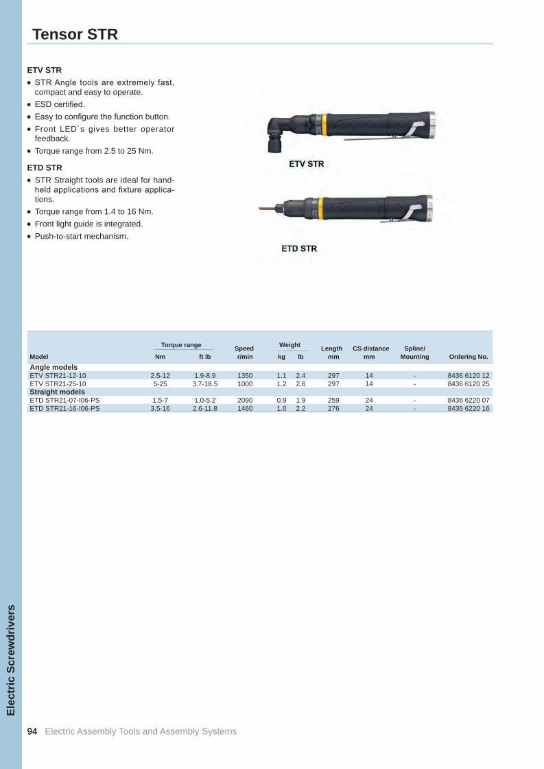
94
Elec
tric
Scr
ewdr
iver
s
94 Electric Assembly Tools and Assembly Systems
Torque range Speed weight Length CS distance Spline/ Model nm ft lb r/min kg lb mm mm Mounting Ordering no.Angle modelsETV STR21-12-10 2.5-12 1.9-8.9 1350 1.1 2.4 297 14 - 8436 6120 12ETV STR21-25-10 5-25 3.7-18.5 1000 1.2 2.6 297 14 - 8436 6120 25Straight modelsETD STR21-07-I06-PS 1.5-7 1.0-5.2 2090 0.9 1.9 259 24 - 8436 6220 07ETD STR21-16-I06-PS 3.5-16 2.6-11.8 1460 1.0 2.2 276 24 - 8436 6220 16
ETV STRl STR Angle tools are extremely fast,
compact and easy to operate.l ESD certifi ed. l Easy to confi gure the function button.l Front LED´s gives better operator
feedback.l Torque range from 2.5 to 25 Nm.
ETD STRl STR Straight tools are ideal for hand-
held applications and fi xture applica-tions.
l Torque range from 1.4 to 16 Nm.l Front light guide is integrated.l Push-to-start mechanism.
Tensor STR
Am_Electricscrewdrivers.indd 94 2012-02-06 11:07:47
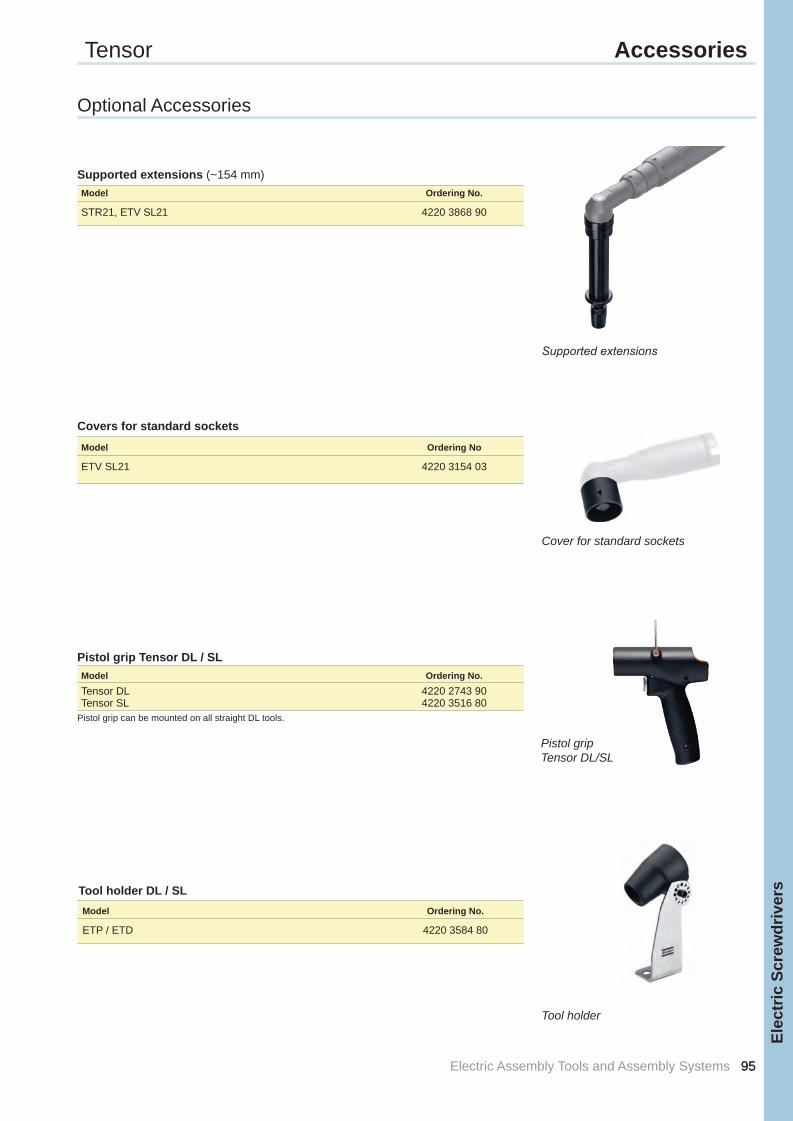
95
Elec
tric
Scr
ewdr
iver
s
Electric Assembly Tools and Assembly Systems 95
Tensor Accessories
Optional Accessories
Tool holder
Pistol grip Tensor DL/SL
Pistol grip Tensor DL / SLModel Ordering no.Tensor DL 4220 2743 90Tensor SL 4220 3516 80
Pistol grip can be mounted on all straight DL tools.
Supported extensions
Supported extensions (~154 mm)Model Ordering no.
STR21, ETV SL21 4220 3868 90
Covers for standard socketsModel Ordering no
ETV SL21 4220 3154 03
Cover for standard sockets
Tool holder DL / SLModel Ordering no.
ETP / ETD 4220 3584 80
Am_Electricscrewdrivers.indd 95 2012-02-06 11:07:57
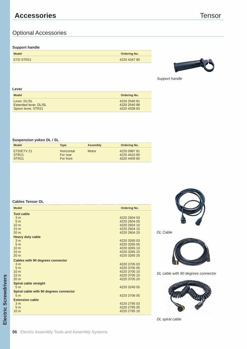
96
Elec
tric
Scr
ewdr
iver
s
96 Electric Assembly Tools and Assembly Systems
Cables Tensor DL
DL Cable
DL cable with 90 degrees connector
DL spiral cable
Accessories Tensor
Optional Accessories
Support handleModel Ordering no.
ETD STR21 4220 4347 80
Support handle
LeverModel Ordering no.
Lever, DL/SL 4220 2540 81Extended lever, DL/SL 4220 2540 88Spoon lever, STR21 4220 4338 83
Suspension yokes DL / SLModel Type Assembly Ordering no.
ETD/ETV 21 Horizontal Motor 4220 0987 81STR21 For rear 4220 4410 80STR21 For front 4220 4409 80
Model Ordering no.
Tool cable 3 m 4220 2604 03 5 m 4220 2604 0510 m 4220 2604 1015 m 4220 2604 1520 m 4220 2604 20Heavy duty cable 3 m 4220 3265 03 5 m 4220 3265 0510 m 4220 3265 1015 m 4220 3265 1520 m 4220 3265 20Cables with 90 degrees connector 3 m 4220 3705 03 5 m 4220 3705 0510 m 4220 3705 1015 m 4220 3705 1520 m 4220 3705 20Spiral cable straight 5 m 4220 3240 05Spiral cable with 90 degrees connector 5 m 4220 3706 05Extension cable 3 m 4220 2795 03 5 m 4220 2795 0510 m 4220 2795 10
Am_Electricscrewdrivers.indd 96 2012-02-06 11:08:03
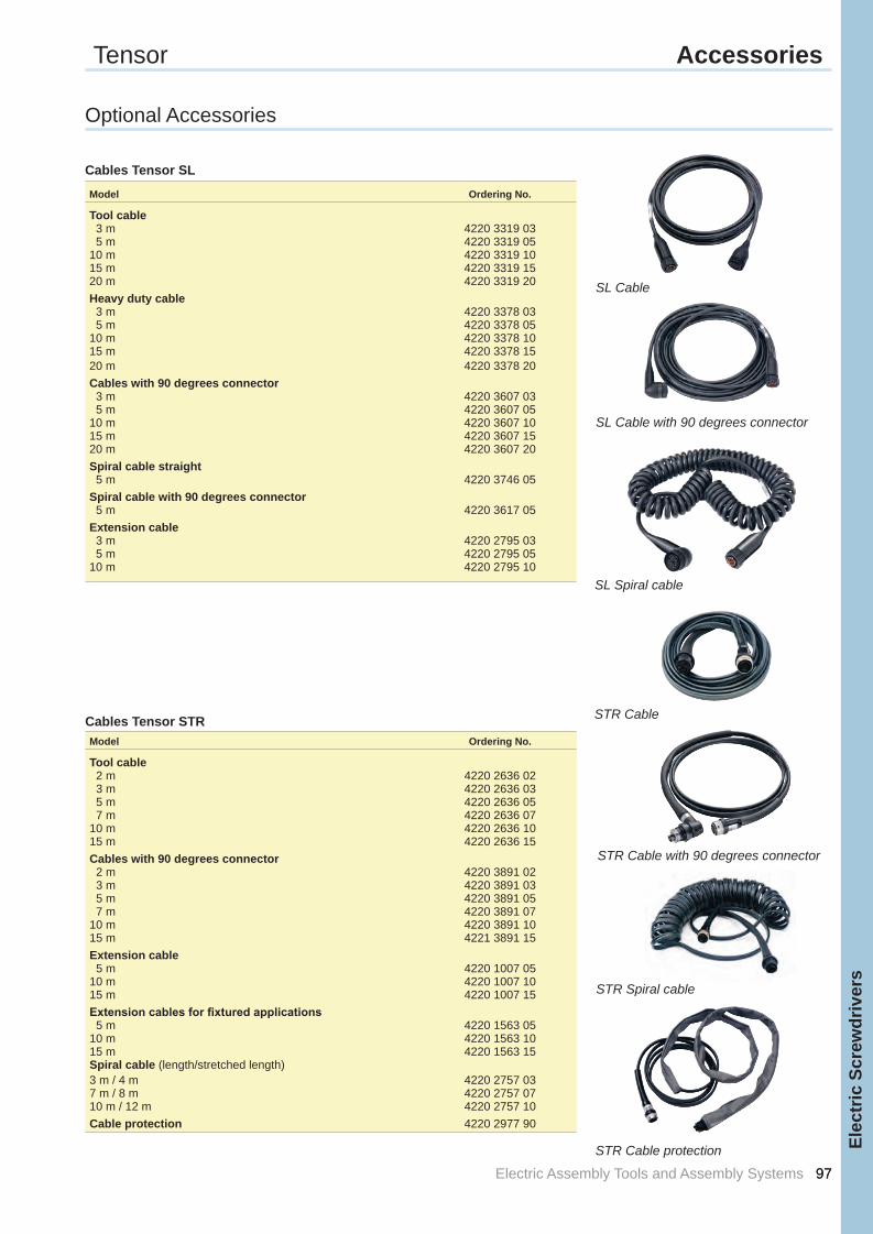
97
Elec
tric
Scr
ewdr
iver
s
Electric Assembly Tools and Assembly Systems 97
SL Cable
SL Cable with 90 degrees connector
SL Spiral cable
Cables Tensor SL
Model Ordering no.
Tool cable 3 m 4220 3319 03 5 m 4220 3319 0510 m 4220 3319 1015 m 4220 3319 1520 m 4220 3319 20Heavy duty cable 3 m 4220 3378 03 5 m 4220 3378 0510 m 4220 3378 1015 m 4220 3378 1520 m 4220 3378 20Cables with 90 degrees connector 3 m 4220 3607 03 5 m 4220 3607 0510 m 4220 3607 1015 m 4220 3607 1520 m 4220 3607 20Spiral cable straight 5 m 4220 3746 05Spiral cable with 90 degrees connector 5 m 4220 3617 05Extension cable 3 m 4220 2795 03 5 m 4220 2795 0510 m 4220 2795 10
Cables Tensor STRModel Ordering no.
Tool cable 2 m 4220 2636 02 3 m 4220 2636 03 5 m 4220 2636 05 7 m 4220 2636 0710 m 4220 2636 1015 m 4220 2636 15Cables with 90 degrees connector 2 m 4220 3891 02 3 m 4220 3891 03 5 m 4220 3891 05 7 m 4220 3891 0710 m 4220 3891 1015 m 4221 3891 15Extension cable 5 m 4220 1007 0510 m 4220 1007 1015 m 4220 1007 15Extension cables for fixtured applications 5 m 4220 1563 0510 m 4220 1563 1015 m 4220 1563 15Spiral cable (length/stretched length)3 m / 4 m 4220 2757 037 m / 8 m 4220 2757 0710 m / 12 m 4220 2757 10Cable protection 4220 2977 90
Tensor Accessories
Optional Accessories
STR Cable
STR Cable with 90 degrees connector
STR Spiral cable
STR Cable protection
Am_Electricscrewdrivers.indd 97 2012-02-06 11:08:17

El
ectr
ic N
utru
nner
s
98 Electric Assembly Tools and Systems
Introduction – Electric Nutrunners
Tensor – the operators' choice
Productivity gainsAtlas Copco’s unique Tensor motors give the Tensor range outstanding spin-dle speeds and, thus, help you achieve lower cycle times in your operation. Ex -ceptional ergonomics in terms of bal -ance, grip and low weight make the tools a favorite of the operators and increase individual productivity.
Operator feedbackAll Tensor tools are equipped with LED’s that will indicate the tightening result, green light for tightening OK and red light for NOK. Tensor ST and STR have con-figurable LED’s and an integrated speak-er for indicating results via audio signals.
Lowest cost of operation At Atlas Copco we believe that quality is the road to lowest cost of operation over time. A maintained Tensor tool produces the same performance year after year at minimum and predictable costs while en-suring highest possible uptime.
Tensor DL: quality criticalThe Tensor DL range is used for qual-ity critical screws. Optimized for small screw assembly, the DL is the electric choice in the low torque segment.
Tensor SL: low torque saf ety critical, configurable tool functionsThe Tensor SL range is opt imized for safety critical small screw assembly. It offers compact screwdriver ergonom -ics, combined with traceability and error proofing capabilities.
Tensor DS: quality criticalTensor DS is used for quality critical ap-plications not requiring traceable meas-ured torque value. DS of fers major pro-ductivity and quality gains compared with conventional tooling.
Tensor S: safety criticalTensor S i s the well proven range for safety critical applications where trace-ability and error proofing capability is re-quired.
Tensor ST: safety critical, configurable tool functionsThe second generation of Tensor tools was developed with low weight and pro-ductivity in mind. Tensor ST has an in -ternal bus connection for intelligent ac-cessories such as a barcode reader and torque selector switch.
The Tensor range of electric assembly tools covers all station and assembly line re-quirements for safety critical and quality critical fastening applications. At Atlas Copco we have a proud legacy of putting the operator first and we continuously improve the ergonomic features on each new generation of Tensor tools. Tensor is also one of the most advanced tool ranges on the market in terms of high power-to-weight ratios and operator guidance in the form of clear result feedback via LED’s or audio signals.
Tensor STR: safety critical, configurable tool functionsThe latest generation of Tensor tools where ergonomics and product ivity are taken to a new level.
Am_Electricnutrunner.indd 98 2012-02-06 13:16:22
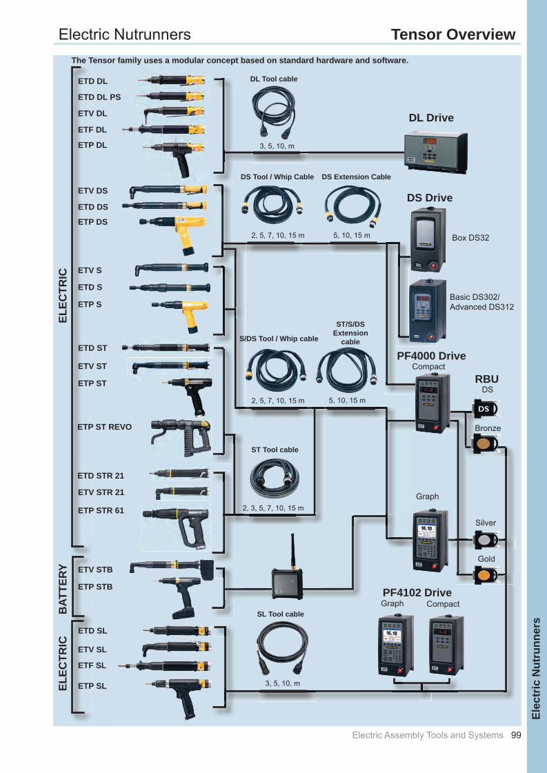
Elec
tric
Nut
runn
ers
Electric Assembly Tools and Systems 99
ETV DS
ETP DS
ETD DS
ETV S
ETP S
ETD S
ETD ST
ETV ST
ETD DL PS
ETV DL
ETD DL
ETP DL
ETP ST
ETD SL
ETV SL
ETF DL
ETP SL
ETF SL
ETV STB
ETP STB
ETP ST REVO
ETV STR 21
ETP STR 61
ETD STR 21
Electric Nutrunners Tensor Overview EL
ECTR
ICB
ATTE
RYEL
ECTR
IC
DS Tool / Whip Cable
The Tensor family uses a modular concept based on standard hardware and software.
S/DS Tool / Whip cable
DS Extension Cable
PF4000 Drive
ST/S/DS Extension
cable
Silver
Gold
Basic DS302/Advanced DS312
Compact
Graph
DS Drive
DL Drive
DL Tool cable
ST Tool cable
SL Tool cable
PF4102 Drive
Box DS32
RBUDS
Bronze
3, 5, 10, m
2, 5, 7, 10, 15 m 5, 10, 15 m
5, 10, 15 m2, 5, 7, 10, 15 m
2, 3, 5, 7, 10, 15 m
3, 5, 10, m
Graph Compact
Am_Electricnutrunner.indd 99 2012-02-06 13:17:23
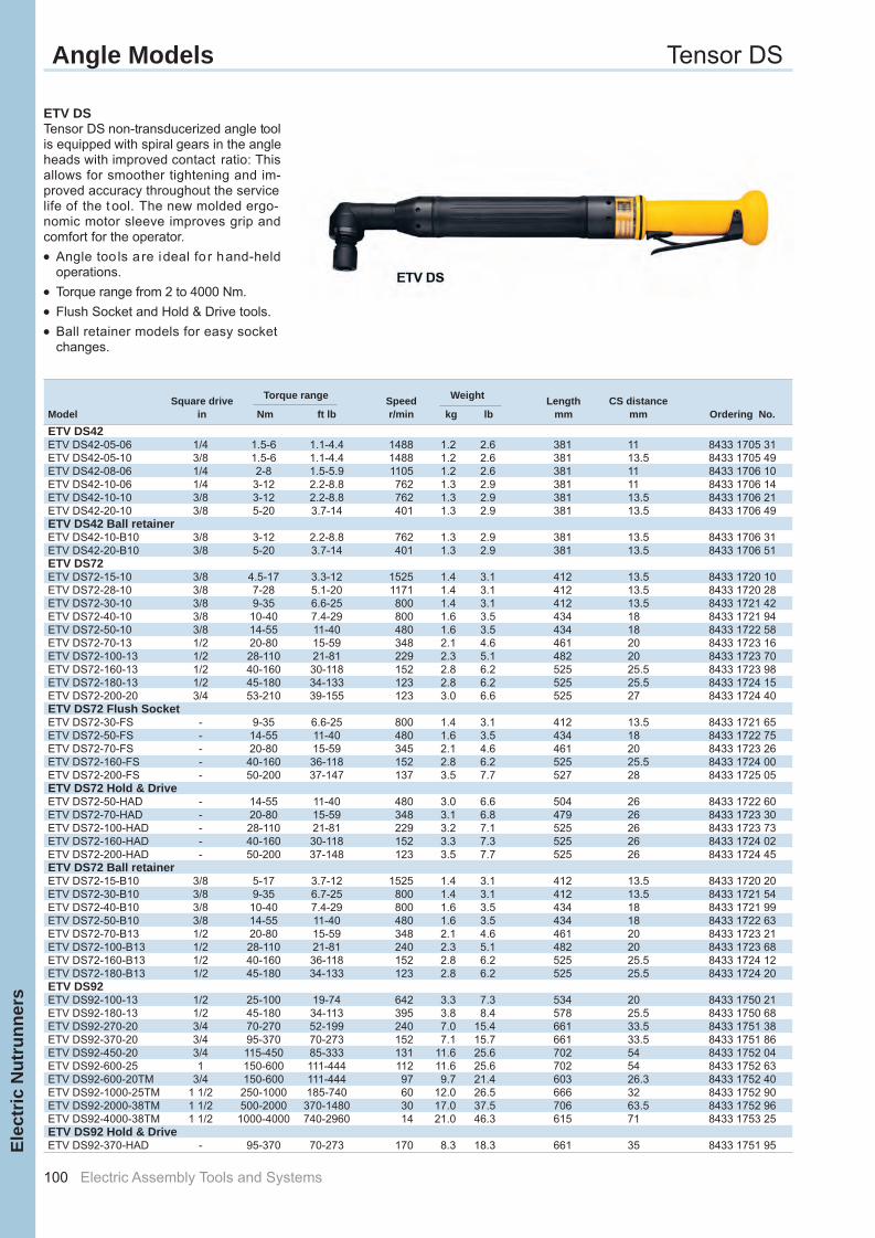
El
ectr
ic N
utru
nner
s
100 Electric Assembly Tools and Systems
Angle Models Tensor DS
ETV DSTensor DS non-transducerized angle tool is equipped with spiral gears in the angle heads with improved contact ratio: This allows for smoother tightening and im-proved accuracy throughout the service life of the t ool. The new molded ergo-nomic motor sleeve improves grip and comfort for the operator.� Angle too ls a re ideal fo r hand-held
operations.� Torque range from 2 to 4000 Nm.� Flush Socket and Hold & Drive tools.� Ball retainer models for easy socket
changes.
Square drive Torque range Speed Weight Length CS distance Model in Nm ft lb r/min kg lb mm mm Ordering No.ETV DS42 ETV DS42-05-06 1/4 1.5-6 1.1-4.4 1488 1.2 2.6 381 11 8433 1705 31ETV DS42-05-10 3/8 1.5-6 1.1-4.4 1488 1.2 2.6 381 13.5 8433 1705 49ETV DS42-08-06 1/4 2-8 1.5-5.9 1105 1.2 2.6 381 11 8433 1706 10ETV DS42-10-06 1/4 3-12 2.2-8.8 762 1.3 2.9 381 11 8433 1706 14ETV DS42-10-10 3/8 3-12 2.2-8.8 762 1.3 2.9 381 13.5 8433 1706 21ETV DS42-20-10 3/8 5-20 3.7-14 401 1.3 2.9 381 13.5 8433 1706 49ETV DS42 Ball retainer ETV DS42-10-B10 3/8 3-12 2.2-8.8 762 1.3 2.9 381 13.5 8433 1706 31ETV DS42-20-B10 3/8 5-20 3.7-14 401 1.3 2.9 381 13.5 8433 1706 51ETV DS72 ETV DS72-15-10 3/8 4.5-17 3.3-12 1525 1.4 3.1 412 13.5 8433 1720 10ETV DS72-28-10 3/8 7-28 5.1-20 1171 1.4 3.1 412 13.5 8433 1720 28ETV DS72-30-10 3/8 9-35 6.6-25 800 1.4 3.1 412 13.5 8433 1721 42ETV DS72-40-10 3/8 10-40 7.4-29 800 1.6 3.5 434 18 8433 1721 94ETV DS72-50-10 3/8 14-55 11-40 480 1.6 3.5 434 18 8433 1722 58ETV DS72-70-13 1/2 20-80 15-59 348 2.1 4.6 461 20 8433 1723 16ETV DS72-100-13 1/2 28-110 21-81 229 2.3 5.1 482 20 8433 1723 70ETV DS72-160-13 1/2 40-160 30-118 152 2.8 6.2 525 25.5 8433 1723 98ETV DS72-180-13 1/2 45-180 34-133 123 2.8 6.2 525 25.5 8433 1724 15ETV DS72-200-20 3/4 53-210 39-155 123 3.0 6.6 525 27 8433 1724 40ETV DS72 Flush Socket ETV DS72-30-FS - 9-35 6.6-25 800 1.4 3.1 412 13.5 8433 1721 65ETV DS72-50-FS - 14-55 11-40 480 1.6 3.5 434 18 8433 1722 75ETV DS72-70-FS - 20-80 15-59 345 2.1 4.6 461 20 8433 1723 26ETV DS72-160-FS - 40-160 36-118 152 2.8 6.2 525 25.5 8433 1724 00ETV DS72-200-FS - 50-200 37-147 137 3.5 7.7 527 28 8433 1725 05ETV DS72 Hold & Drive ETV DS72-50-HAD - 14-55 11-40 480 3.0 6.6 504 26 8433 1722 60ETV DS72-70-HAD - 20-80 15-59 348 3.1 6.8 479 26 8433 1723 30ETV DS72-100-HAD - 28-110 21-81 229 3.2 7.1 525 26 8433 1723 73ETV DS72-160-HAD - 40-160 30-118 152 3.3 7.3 525 26 8433 1724 02ETV DS72-200-HAD - 50-200 37-148 123 3.5 7.7 525 26 8433 1724 45ETV DS72 Ball retainer ETV DS72-15-B10 3/8 5-17 3.7-12 1525 1.4 3.1 412 13.5 8433 1720 20ETV DS72-30-B10 3/8 9-35 6.7-25 800 1.4 3.1 412 13.5 8433 1721 54ETV DS72-40-B10 3/8 10-40 7.4-29 800 1.6 3.5 434 18 8433 1721 99ETV DS72-50-B10 3/8 14-55 11-40 480 1.6 3.5 434 18 8433 1722 63ETV DS72-70-B13 1/2 20-80 15-59 348 2.1 4.6 461 20 8433 1723 21ETV DS72-100-B13 1/2 28-110 21-81 240 2.3 5.1 482 20 8433 1723 68ETV DS72-160-B13 1/2 40-160 36-118 152 2.8 6.2 525 25.5 8433 1724 12ETV DS72-180-B13 1/2 45-180 34-133 123 2.8 6.2 525 25.5 8433 1724 20ETV DS92 ETV DS92-100-13 1/2 25-100 19-74 642 3.3 7.3 534 20 8433 1750 21ETV DS92-180-13 1/2 45-180 34-113 395 3.8 8.4 578 25.5 8433 1750 68ETV DS92-270-20 3/4 70-270 52-199 240 7.0 15.4 661 33.5 8433 1751 38ETV DS92-370-20 3/4 95-370 70-273 152 7.1 15.7 661 33.5 8433 1751 86ETV DS92-450-20 3/4 115-450 85-333 131 11.6 25.6 702 54 8433 1752 04ETV DS92-600-25 1 150-600 111-444 112 11.6 25.6 702 54 8433 1752 63ETV DS92-600-20TM 3/4 150-600 111-444 97 9.7 21.4 603 26.3 8433 1752 40ETV DS92-1000-25TM 1 1/2 250-1000 185-740 60 12.0 26.5 666 32 8433 1752 90ETV DS92-2000-38TM 1 1/2 500-2000 370-1480 30 17.0 37.5 706 63.5 8433 1752 96ETV DS92-4000-38TM 1 1/2 1000-4000 740-2960 14 21.0 46.3 615 71 8433 1753 25ETV DS92 Hold & Drive ETV DS92-370-HAD - 95-370 70-273 170 8.3 18.3 661 35 8433 1751 95
Am_Electricnutrunner.indd 100 2012-02-06 13:17:24

Elec
tric
Nut
runn
ers
Electric Assembly Tools and Systems 101
Square drive Torque range Speed Weight Length CS distance Spline/ Model in Nm ft lb r/min kg lb mm mm Mounting Ordering No.ETD DS4ETD DS4-05-10S 3/8 2-5 1.5-3.6 1315 1.1 2.5 380 28 – / 1 8433 0710 29ETD DS4-10-10S 3/8 4-14 3-10 620 1.1 2.5 380 28 – / 1 8433 0710 52ETD DS42-20-10 3/8 5-20 3.7-15 390 1.1 2.5 380 28 – / 1 8433 1711 16ETD DS4 Telescopic ETD DS4-05-10ST 3/8 2-5 1.5-3.6 1315 1.3 2.9 418 28 2 / 2 8433 0710 37ETD DS4-10-10ST 3/8 4-14 3-10 620 1.3 2.9 418 28 2 / 2 8433 0710 73ETD DS4 Female Hex ETD DS4-02-I06S 1/4 1-2.5 0.7-1.8 2942 1.1 2.5 371 28 – / 1 8433 0710 22ETD DS4-05-I06S 1/4 2-5 1.5-3.6 1310 1.1 2.5 371 28 – / 1 8433 0710 26ETD DS4-10-I06S 1/4 4-14 3-10 620 1.1 2.5 371 28 – / 1 8433 0710 46ETD DS7 ETD DS7-20-10S 3/8 6-20 4.4-14.5 1240 1.4 3.1 411 28 – / 1 8433 0730 23ETD DS72-30-10S 3/8 10-35 7.3-25 745 1.4 3.1 411 28 – / 1 8433 1730 88ETD DS72-50-13S 1/2 17-55 12-40 540 1.9 4.2 456 28 2 / 2 8433 1731 12ETD DS7-70-13S 1/2 21-70 15-51 370 2.2 4.9 477 28 2 / 2 8433 0731 31ETD DS7-90-13S 1/2 28-95 21-69 275 2.2 4.9 477 28 2 / 2 8433 0731 45ETD DS7-120-13S 1/2 38-125 28-91 225 2.2 4.9 477 28 2 / 2 8433 0731 84ETD DS7 Telescopic ETD DS7-20-10ST 3/8 6-20 4.4-14.5 1240 1.5 3.3 449 28 2 / 2 8433 0730 44ETD DS7-30-10ST 3/8 10-35 7.3-25 745 1.5 3.3 449 28 2 / 2 8433 0731 05ETD DS7-50-13ST 1/2 17-55 12-40 540 2.1 4.7 483 28 3 / 5 8433 0731 24ETD DS7-50-13ST50 1/2 17-55 12-40 540 2.2 4.8 540 28 3 / 5 8433 0731 22ETD DS7-70-13ST 1/2 21-70 15-51 370 2.4 5.4 504 29.5 3 / 5 8433 0731 40ETD DS72-70-13ST75 1/2 21-70 15-51 370 2.5 5.5 645 29.5 3 / 5 8433 1731 39ETD DS7-90-13ST 1/2 28-95 21-69 275 2.9 6.5 504 29.5 3 / 5 8433 0731 52ETD DS7-90-13ST50 1/2 28-95 21-69 275 3.0 6.6 562 29.5 3 / 5 8433 0731 64ETD DS7-120-13ST 1/2 38-125 28-91 225 3.0 6.6 504 29.5 3 / 5 8433 0731 96ETD DS7-120-13ST50 1/2 38-125 28-91 225 3.1 6.8 562 29.5 3 / 5 8433 0731 99ETD DS7-200-13ST 1/2 50-200 37-146 225 3.2 7.1 616 29.5 3 / 5 8433 0732 10ETV DS72 Ball retainer ETD DS7-50-B13S 1/2 17-55 12-40 540 1.9 4.2 456 28 2 / 2 8433 0731 20ETD DS7-90-B13S 1/2 28-95 21-69 275 2.2 4.9 477 28 2 / 2 8433 0731 48ETD DS9 ETD DS9-100-13S 1/2 40-100 29-73 715 3.0 6.7 529 32 2 / 2 8433 0756 42ETD DS9-150-13S 1/2 60-150 44-110 455 3.2 7.1 544 32 2 / 2 8433 0757 54ETD DS9-200-13S 1/2 80-200 58-146 340 3.2 7.1 544 32 2 / 2 8433 0758 71ETD DS9-270-20S 3/4 68-270 50-199 220 6.2 14 603 36 6 / 8 8433 0760 53ETD DS9-450-20S 3/4 115-450 85-328 125 7.4 16 639 40.5 6 / 8 8433 0760 71ETD DS92-600-20S 3/4 150-600 110-438 110 7.6 17 639 40.5 6 / 8 8433 1761 29ETD DS9-1000-25S 1 250-1000 184-730 68 12.3 27 769 47 7 / 11 8433 0763 60ETD DS9-1200-25S 1 300-1200 220-880 55 12.3 27 769 47 7 / 11 8433 0763 80ETD DS9-1500-38S 1 1/2 375-1500 280-1100 42 16.8 37 725 68 8 / 12 8433 0763 91ETD DS9-2000-38S 1 1/2 600-2000 440-1475 34 20.5 45 725 68 8 / 12 8433 0764 05ETD DS9-3000-38S 1 1/2 750-3000 550-2200 21 21.7 47.8 809 68 8 / 12 8433 0764 23ETD DS9-4000-38S 1 1/2 1000-4000 730-2950 17 21.7 47.8 809 68 8 / 12 8433 0764 37ETD DS92-4000-38S 1 1/2 1000-4000 730-2950 17 21.7 48 809 68 8 / 12 8433 1764 37
ETD DS� ETD DS inline non-transducerized
tools. The low torque series is ideal for hand-held bench assembly. The high torque tools are well suited for fi xtured applications.
� Torque range from 1 to 4000 Nm.� Telescopic spindles for fi xtured appli-
cations.� Female hex drives for bits.� Swivelling front parts for easy positio-
ning of reaction force.
Tensor DS Straight Models
Continued...
Am_Electricnutrunner.indd 101 2012-02-06 13:17:25
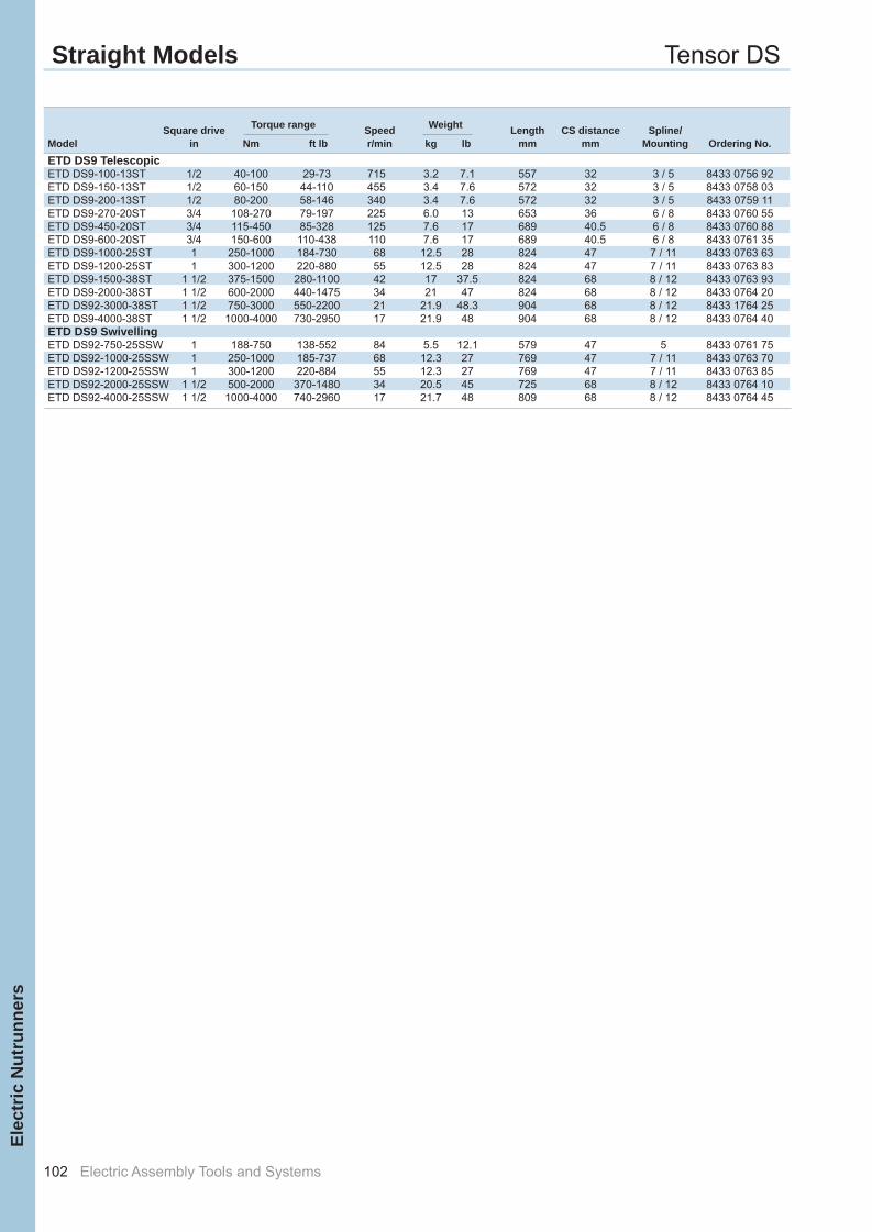
El
ectr
ic N
utru
nner
s
102 Electric Assembly Tools and Systems
Square drive Torque range Speed Weight Length CS distance Spline/ Model in Nm ft lb r/min kg lb mm mm Mounting Ordering No.ETD DS9 Telescopic ETD DS9-100-13ST 1/2 40-100 29-73 715 3.2 7.1 557 32 3 / 5 8433 0756 92ETD DS9-150-13ST 1/2 60-150 44-110 455 3.4 7.6 572 32 3 / 5 8433 0758 03ETD DS9-200-13ST 1/2 80-200 58-146 340 3.4 7.6 572 32 3 / 5 8433 0759 11ETD DS9-270-20ST 3/4 108-270 79-197 225 6.0 13 653 36 6 / 8 8433 0760 55ETD DS9-450-20ST 3/4 115-450 85-328 125 7.6 17 689 40.5 6 / 8 8433 0760 88ETD DS9-600-20ST 3/4 150-600 110-438 110 7.6 17 689 40.5 6 / 8 8433 0761 35ETD DS9-1000-25ST 1 250-1000 184-730 68 12.5 28 824 47 7 / 11 8433 0763 63ETD DS9-1200-25ST 1 300-1200 220-880 55 12.5 28 824 47 7 / 11 8433 0763 83ETD DS9-1500-38ST 1 1/2 375-1500 280-1100 42 17 37.5 824 68 8 / 12 8433 0763 93ETD DS9-2000-38ST 1 1/2 600-2000 440-1475 34 21 47 824 68 8 / 12 8433 0764 20ETD DS92-3000-38ST 1 1/2 750-3000 550-2200 21 21.9 48.3 904 68 8 / 12 8433 1764 25 ETD DS9-4000-38ST 1 1/2 1000-4000 730-2950 17 21.9 48 904 68 8 / 12 8433 0764 40ETD DS9 Swivelling ETD DS92-750-25SSW 1 188-750 138-552 84 5.5 12.1 579 47 5 8433 0761 75ETD DS92-1000-25SSW 1 250-1000 185-737 68 12.3 27 769 47 7 / 11 8433 0763 70ETD DS92-1200-25SSW 1 300-1200 220-884 55 12.3 27 769 47 7 / 11 8433 0763 85ETD DS92-2000-25SSW 1 1/2 500-2000 370-1480 34 20.5 45 725 68 8 / 12 8433 0764 10ETD DS92-4000-25SSW 1 1/2 1000-4000 740-2960 17 21.7 48 809 68 8 / 12 8433 0764 45
Straight Models Tensor DS
Am_Electricnutrunner.indd 102 2012-02-06 13:17:25
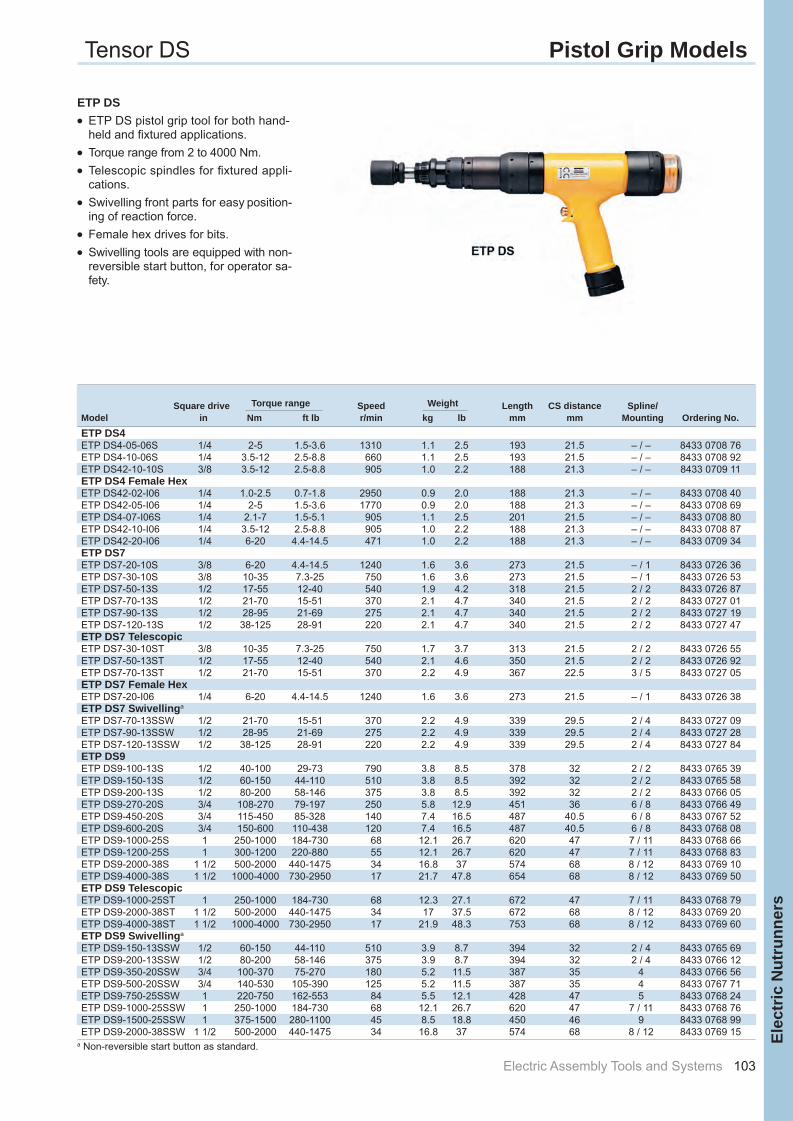
Elec
tric
Nut
runn
ers
Electric Assembly Tools and Systems 103
Square drive Torque range Speed Weight Length CS distance Spline/ Model in Nm ft lb r/min kg lb mm mm Mounting Ordering No.ETP DS4ETP DS4-05-06S 1/4 2-5 1.5-3.6 1310 1.1 2.5 193 21.5 – / – 8433 0708 76ETP DS4-10-06S 1/4 3.5-12 2.5-8.8 660 1.1 2.5 193 21.5 – / – 8433 0708 92ETP DS42-10-10S 3/8 3.5-12 2.5-8.8 905 1.0 2.2 188 21.3 – / – 8433 0709 11ETP DS4 Female Hex ETP DS42-02-I06 1/4 1.0-2.5 0.7-1.8 2950 0.9 2.0 188 21.3 – / – 8433 0708 40ETP DS42-05-I06 1/4 2-5 1.5-3.6 1770 0.9 2.0 188 21.3 – / – 8433 0708 69ETP DS4-07-I06S 1/4 2.1-7 1.5-5.1 905 1.1 2.5 201 21.5 – / – 8433 0708 80ETP DS42-10-I06 1/4 3.5-12 2.5-8.8 905 1.0 2.2 188 21.3 – / – 8433 0708 87ETP DS42-20-I06 1/4 6-20 4.4-14.5 471 1.0 2.2 188 21.3 – / – 8433 0709 34ETP DS7 ETP DS7-20-10S 3/8 6-20 4.4-14.5 1240 1.6 3.6 273 21.5 – / 1 8433 0726 36ETP DS7-30-10S 3/8 10-35 7.3-25 750 1.6 3.6 273 21.5 – / 1 8433 0726 53ETP DS7-50-13S 1/2 17-55 12-40 540 1.9 4.2 318 21.5 2 / 2 8433 0726 87ETP DS7-70-13S 1/2 21-70 15-51 370 2.1 4.7 340 21.5 2 / 2 8433 0727 01ETP DS7-90-13S 1/2 28-95 21-69 275 2.1 4.7 340 21.5 2 / 2 8433 0727 19ETP DS7-120-13S 1/2 38-125 28-91 220 2.1 4.7 340 21.5 2 / 2 8433 0727 47ETP DS7 Telescopic ETP DS7-30-10ST 3/8 10-35 7.3-25 750 1.7 3.7 313 21.5 2 / 2 8433 0726 55ETP DS7-50-13ST 1/2 17-55 12-40 540 2.1 4.6 350 21.5 2 / 2 8433 0726 92ETP DS7-70-13ST 1/2 21-70 15-51 370 2.2 4.9 367 22.5 3 / 5 8433 0727 05ETP DS7 Female Hex ETP DS7-20-I06 1/4 6-20 4.4-14.5 1240 1.6 3.6 273 21.5 – / 1 8433 0726 38ETP DS7 Swivellinga ETP DS7-70-13SSW 1/2 21-70 15-51 370 2.2 4.9 339 29.5 2 / 4 8433 0727 09ETP DS7-90-13SSW 1/2 28-95 21-69 275 2.2 4.9 339 29.5 2 / 4 8433 0727 28ETP DS7-120-13SSW 1/2 38-125 28-91 220 2.2 4.9 339 29.5 2 / 4 8433 0727 84ETP DS9 ETP DS9-100-13S 1/2 40-100 29-73 790 3.8 8.5 378 32 2 / 2 8433 0765 39ETP DS9-150-13S 1/2 60-150 44-110 510 3.8 8.5 392 32 2 / 2 8433 0765 58ETP DS9-200-13S 1/2 80-200 58-146 375 3.8 8.5 392 32 2 / 2 8433 0766 05ETP DS9-270-20S 3/4 108-270 79-197 250 5.8 12.9 451 36 6 / 8 8433 0766 49ETP DS9-450-20S 3/4 115-450 85-328 140 7.4 16.5 487 40.5 6 / 8 8433 0767 52ETP DS9-600-20S 3/4 150-600 110-438 120 7.4 16.5 487 40.5 6 / 8 8433 0768 08ETP DS9-1000-25S 1 250-1000 184-730 68 12.1 26.7 620 47 7 / 11 8433 0768 66ETP DS9-1200-25S 1 300-1200 220-880 55 12.1 26.7 620 47 7 / 11 8433 0768 83ETP DS9-2000-38S 1 1/2 500-2000 440-1475 34 16.8 37 574 68 8 / 12 8433 0769 10ETP DS9-4000-38S 1 1/2 1000-4000 730-2950 17 21.7 47.8 654 68 8 / 12 8433 0769 50ETP DS9 Telescopic ETP DS9-1000-25ST 1 250-1000 184-730 68 12.3 27.1 672 47 7 / 11 8433 0768 79ETP DS9-2000-38ST 1 1/2 500-2000 440-1475 34 17 37.5 672 68 8 / 12 8433 0769 20ETP DS9-4000-38ST 1 1/2 1000-4000 730-2950 17 21.9 48.3 753 68 8 / 12 8433 0769 60ETP DS9 Swivellinga ETP DS9-150-13SSW 1/2 60-150 44-110 510 3.9 8.7 394 32 2 / 4 8433 0765 69ETP DS9-200-13SSW 1/2 80-200 58-146 375 3.9 8.7 394 32 2 / 4 8433 0766 12ETP DS9-350-20SSW 3/4 100-370 75-270 180 5.2 11.5 387 35 4 8433 0766 56ETP DS9-500-20SSW 3/4 140-530 105-390 125 5.2 11.5 387 35 4 8433 0767 71ETP DS9-750-25SSW 1 220-750 162-553 84 5.5 12.1 428 47 5 8433 0768 24ETP DS9-1000-25SSW 1 250-1000 184-730 68 12.1 26.7 620 47 7 / 11 8433 0768 76ETP DS9-1500-25SSW 1 375-1500 280-1100 45 8.5 18.8 450 46 9 8433 0768 99ETP DS9-2000-38SSW 1 1/2 500-2000 440-1475 34 16.8 37 574 68 8 / 12 8433 0769 15
Tensor DS Pistol Grip Models
a Non-reversible start button as standard.
ETP DS� ETP DS pistol grip tool for both hand-
held and fi xtured applications.� Torque range from 2 to 4000 Nm.� Telescopic spindles for fi xtured appli-
cations.� Swivelling front parts for easy position-
ing of reaction force.� Female hex drives for bits.� Swivelling tools are equipped with non-
reversible start button, for operator sa-fety.
Am_Electricnutrunner.indd 103 2012-02-06 13:17:25
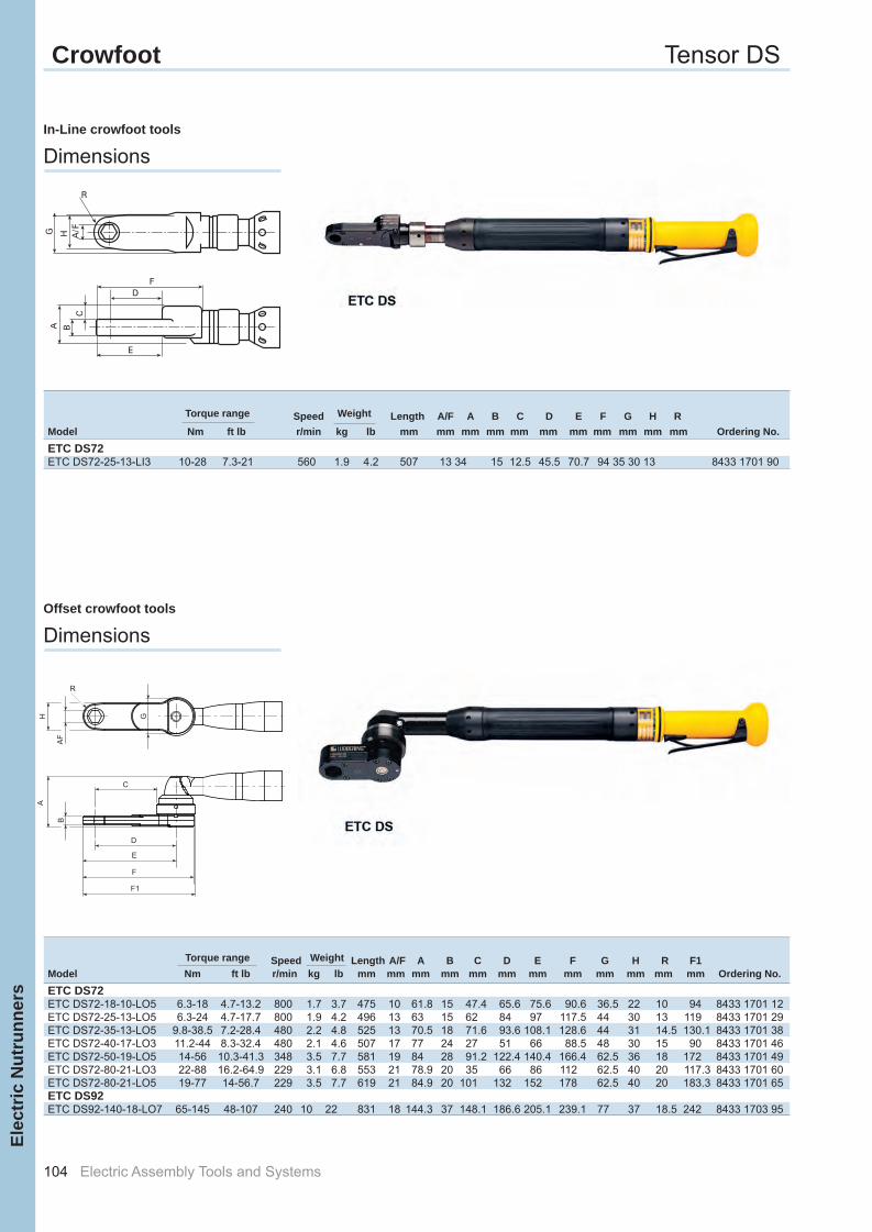
El
ectr
ic N
utru
nner
s
104 Electric Assembly Tools and Systems
H
AF
R
G
C
D
E
F
F1
A
B
Torque range Speed Weight Length A/F A B C D E F G H R Model Nm ft lb r/min kg lb mm mm mm mm mm mm mm mm mm mm mm Ordering No.ETC DS72 ETC DS72-25-13-LI3 10-28 7.3-21 560 1.9 4.2 507 13 34 15 12.5 45.5 70.7 94 35 30 13 8433 1701 90
Crowfoot Tensor DS
Torque range Speed Weight Length A/F A B C D E F G H R F1 Model Nm ft lb r/min kg lb mm mm mm mm mm mm mm mm mm mm mm mm Ordering No.ETC DS72 ETC DS72-18-10-LO5 6.3-18 4.7-13.2 800 1.7 3.7 475 10 61.8 15 47.4 65.6 75.6 90.6 36.5 22 10 94 8433 1701 12ETC DS72-25-13-LO5 6.3-24 4.7-17.7 800 1.9 4.2 496 13 63 15 62 84 97 117.5 44 30 13 119 8433 1701 29ETC DS72-35-13-LO5 9.8-38.5 7.2-28.4 480 2.2 4.8 525 13 70.5 18 71.6 93.6 108.1 128.6 44 31 14.5 130.1 8433 1701 38ETC DS72-40-17-LO3 11.2-44 8.3-32.4 480 2.1 4.6 507 17 77 24 27 51 66 88.5 48 30 15 90 8433 1701 46ETC DS72-50-19-LO5 14-56 10.3-41.3 348 3.5 7.7 581 19 84 28 91.2 122.4 140.4 166.4 62.5 36 18 172 8433 1701 49ETC DS72-80-21-LO3 22-88 16.2-64.9 229 3.1 6.8 553 21 78.9 20 35 66 86 112 62.5 40 20 117.3 8433 1701 60ETC DS72-80-21-LO5 19-77 14-56.7 229 3.5 7.7 619 21 84.9 20 101 132 152 178 62.5 40 20 183.3 8433 1701 65ETC DS92 ETC DS92-140-18-LO7 65-145 48-107 240 10 22 831 18 144.3 37 148.1 186.6 205.1 239.1 77 37 18.5 242 8433 1703 95
In-Line crowfoot tools
Dimensions
Offset crowfoot tools
Dimensions
Am_Electricnutrunner.indd 104 2012-02-06 13:17:27
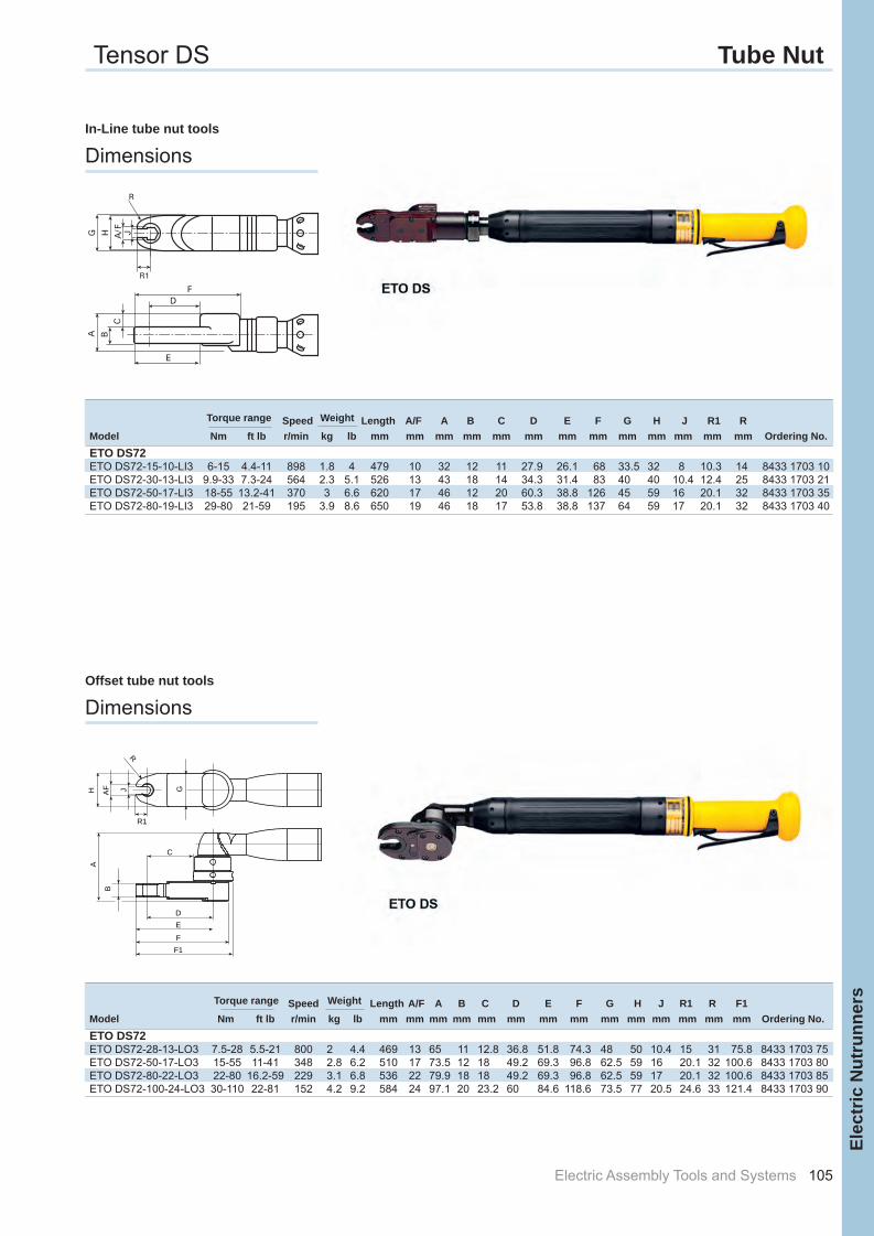
Elec
tric
Nut
runn
ers
Electric Assembly Tools and Systems 105
R1
R
DE
FF1
C
R
H AF J G
A
B
R1
Torque range Speed Weight Length A/F A B C D E F G H J R1 R Model Nm ft lb r/min kg lb mm mm mm mm mm mm mm mm mm mm mm mm mm Ordering No.ETO DS72ETO DS72-15-10-LI3 6-15 4.4-11 898 1.8 4 479 10 32 12 11 27.9 26.1 68 33.5 32 8 10.3 14 8433 1703 10ETO DS72-30-13-LI3 9.9-33 7.3-24 564 2.3 5.1 526 13 43 18 14 34.3 31.4 83 40 40 10.4 12.4 25 8433 1703 21ETO DS72-50-17-LI3 18-55 13.2-41 370 3 6.6 620 17 46 12 20 60.3 38.8 126 45 59 16 20.1 32 8433 1703 35ETO DS72-80-19-LI3 29-80 21-59 195 3.9 8.6 650 19 46 18 17 53.8 38.8 137 64 59 17 20.1 32 8433 1703 40
Torque range Speed Weight Length A/F A B C D E F G H J R1 R F1Model Nm ft lb r/min kg lb mm mm mm mm mm mm mm mm mm mm mm mm mm mm Ordering No.ETO DS72ETO DS72-28-13-LO3 7.5-28 5.5-21 800 2 4.4 469 13 65 11 12.8 36.8 51.8 74.3 48 50 10.4 15 31 75.8 8433 1703 75ETO DS72-50-17-LO3 15-55 11-41 348 2.8 6.2 510 17 73.5 12 18 49.2 69.3 96.8 62.5 59 16 20.1 32 100.6 8433 1703 80ETO DS72-80-22-LO3 22-80 16.2-59 229 3.1 6.8 536 22 79.9 18 18 49.2 69.3 96.8 62.5 59 17 20.1 32 100.6 8433 1703 85ETO DS72-100-24-LO3 30-110 22-81 152 4.2 9.2 584 24 97.1 20 23.2 60 84.6 118.6 73.5 77 20.5 24.6 33 121.4 8433 1703 90
In-Line tube nut tools
Dimensions
Offset tube nut tools
Dimensions
Tensor DS Tube Nut
Am_Electricnutrunner.indd 105 2012-02-06 13:17:29
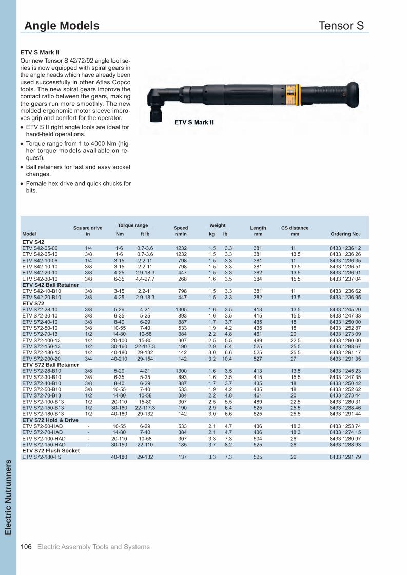
El
ectr
ic N
utru
nner
s
106 Electric Assembly Tools and Systems
Square drive Torque range Speed Weight Length CS distance Model in Nm ft lb r/min kg lb mm mm Ordering No.ETV S42ETV S42-05-06 1/4 1-6 0.7-3.6 1232 1.5 3.3 381 11 8433 1236 12ETV S42-05-10 3/8 1-6 0.7-3.6 1232 1.5 3.3 381 13.5 8433 1236 26ETV S42-10-06 1/4 3-15 2.2-11 798 1.5 3.3 381 11 8433 1236 35ETV S42-10-10 3/8 3-15 2.2-11 798 1.5 3.3 381 13.5 8433 1236 51ETV S42-20-10 3/8 4-25 2.9-18.3 447 1.5 3.3 382 13.5 8433 1236 91ETV S42-30-10 3/8 6-35 4.4-27.7 268 1.6 3.5 384 15.5 8433 1237 04ETV S42 Ball RetainerETV S42-10-B10 3/8 3-15 2.2-11 798 1.5 3.3 381 11 8433 1236 62ETV S42-20-B10 3/8 4-25 2.9-18.3 447 1.5 3.3 382 13.5 8433 1236 95ETV S72ETV S72-28-10 3/8 5-29 4-21 1305 1.6 3.5 413 13.5 8433 1245 20ETV S72-30-10 3/8 6-35 5-25 893 1.6 3.5 415 15.5 8433 1247 33ETV S72-40-10 3/8 8-40 6-29 887 1.7 3.7 435 18 8433 1250 00ETV S72-50-10 3/8 10-55 7-40 533 1.9 4.2 435 18 8433 1252 87ETV S72-70-13 1/2 14-80 10-58 384 2.2 4.8 461 20 8433 1273 09ETV S72-100-13 1/2 20-100 15-80 307 2.5 5.5 489 22.5 8433 1280 00ETV S72-150-13 1/2 30-160 22-117.3 190 2.9 6.4 525 25.5 8433 1288 67ETV S72-180-13 1/2 40-180 29-132 142 3.0 6.6 525 25.5 8433 1291 17ETV S72-200-20 3/4 40-210 29-154 142 3.2 10.4 527 27 8433 1291 35ETV S72 Ball RetainerETV S72-28-B10 3/8 5-29 4-21 1300 1.6 3.5 413 13.5 8433 1245 23ETV S72-30-B10 3/8 6-35 5-25 893 1.6 3.5 415 15.5 8433 1247 35ETV S72-40-B10 3/8 8-40 6-29 887 1.7 3.7 435 18 8433 1250 42ETV S72-50-B10 3/8 10-55 7-40 533 1.9 4.2 435 18 8433 1252 62ETV S72-70-B13 1/2 14-80 10-58 384 2.2 4.8 461 20 8433 1273 44ETV S72-100-B13 1/2 20-110 15-80 307 2.5 5.5 489 22.5 8433 1280 31ETV S72-150-B13 1/2 30-160 22-117.3 190 2.9 6.4 525 25.5 8433 1288 46ETV S72-180-B13 1/2 40-180 29-132 142 3.0 6.6 525 25.5 8433 1291 44ETV S72 Hold & DriveETV S72-50-HAD - 10-55 6-29 533 2.1 4.7 436 18.3 8433 1253 74ETV S72-70-HAD - 14-80 7-40 384 2.1 4.7 436 18.3 8433 1274 15ETV S72-100-HAD - 20-110 10-58 307 3.3 7.3 504 26 8433 1280 97ETV S72-150-HAD - 30-150 22-110 185 3.7 8.2 525 26 8433 1288 93ETV S72 Flush SocketETV S72-180-FS 40-180 29-132 137 3.3 7.3 525 26 8433 1291 79
Angle Models Tensor S
ETV S Mark IIOur new Tensor S 42/72/92 angle tool se-ries is now equipped with spiral gears in the angle heads which have already been used successfully in other Atlas Copco tools. The new spiral gears improve the contact ratio between the gears, making the gears run more smoothly. The new molded ergonomic motor sleeve impro-ves grip and comfort for the operator.� ETV S II right angle tools are ideal for
hand-held operations.� Torque range from 1 to 4000 Nm (hig-
her torque mo dels avail able on re-quest).
� Ball retainers for fast and easy socket changes.
� Female hex drive and quick chucks for bits.
Am_Electricnutrunner.indd 106 2012-02-06 13:17:29
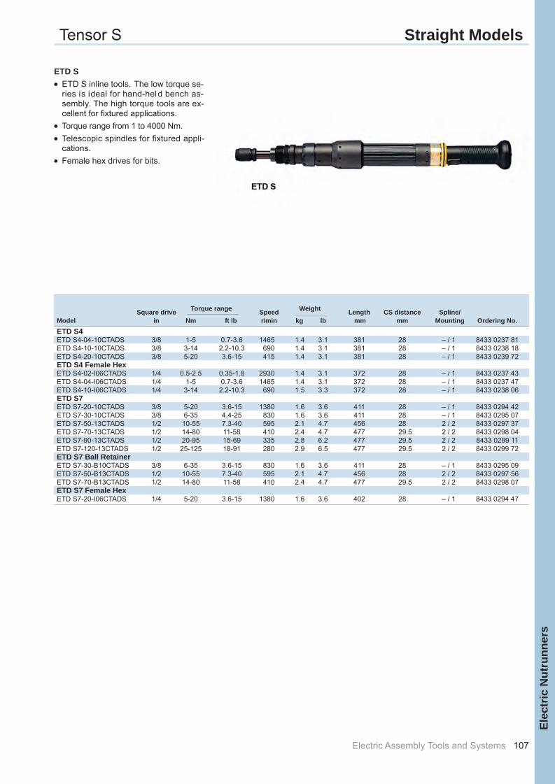
Elec
tric
Nut
runn
ers
Electric Assembly Tools and Systems 107
Square drive Torque range Speed Weight Length CS distance Spline/ Model in Nm ft lb r/min kg lb mm mm Mounting Ordering No.ETD S4ETD S4-04-10CTADS 3/8 1-5 0.7-3.6 1465 1.4 3.1 381 28 – / 1 8433 0237 81ETD S4-10-10CTADS 3/8 3-14 2.2-10.3 690 1.4 3.1 381 28 – / 1 8433 0238 18ETD S4-20-10CTADS 3/8 5-20 3.6-15 415 1.4 3.1 381 28 – / 1 8433 0239 72ETD S4 Female HexETD S4-02-I06CTADS 1/4 0.5-2.5 0.35-1.8 2930 1.4 3.1 372 28 – / 1 8433 0237 43ETD S4-04-I06CTADS 1/4 1-5 0.7-3.6 1465 1.4 3.1 372 28 – / 1 8433 0237 47ETD S4-10-I06CTADS 1/4 3-14 2.2-10.3 690 1.5 3.3 372 28 – / 1 8433 0238 06ETD S7ETD S7-20-10CTADS 3/8 5-20 3.6-15 1380 1.6 3.6 411 28 – / 1 8433 0294 42ETD S7-30-10CTADS 3/8 6-35 4.4-25 830 1.6 3.6 411 28 – / 1 8433 0295 07ETD S7-50-13CTADS 1/2 10-55 7.3-40 595 2.1 4.7 456 28 2 / 2 8433 0297 37ETD S7-70-13CTADS 1/2 14-80 11-58 410 2.4 4.7 477 29.5 2 / 2 8433 0298 04ETD S7-90-13CTADS 1/2 20-95 15-69 335 2.8 6.2 477 29.5 2 / 2 8433 0299 11ETD S7-120-13CTADS 1/2 25-125 18-91 280 2.9 6.5 477 29.5 2 / 2 8433 0299 72ETD S7 Ball RetainerETD S7-30-B10CTADS 3/8 6-35 3.6-15 830 1.6 3.6 411 28 – / 1 8433 0295 09ETD S7-50-B13CTADS 1/2 10-55 7.3-40 595 2.1 4.7 456 28 2 / 2 8433 0297 56ETD S7-70-B13CTADS 1/2 14-80 11-58 410 2.4 4.7 477 29.5 2 / 2 8433 0298 07ETD S7 Female HexETD S7-20-I06CTADS 1/4 5-20 3.6-15 1380 1.6 3.6 402 28 – / 1 8433 0294 47
ETD S� ETD S inline tools. The low torque se-
ries is ideal for hand-held bench as-sembly. The high torque tools are ex-cellent for fi xtured applications.
� Torque range from 1 to 4000 Nm.� Telescopic spindles for fi xtured appli-
cations.� Female hex drives for bits.
Tensor S Straight Models
Am_Electricnutrunner.indd 107 2012-02-06 13:17:30
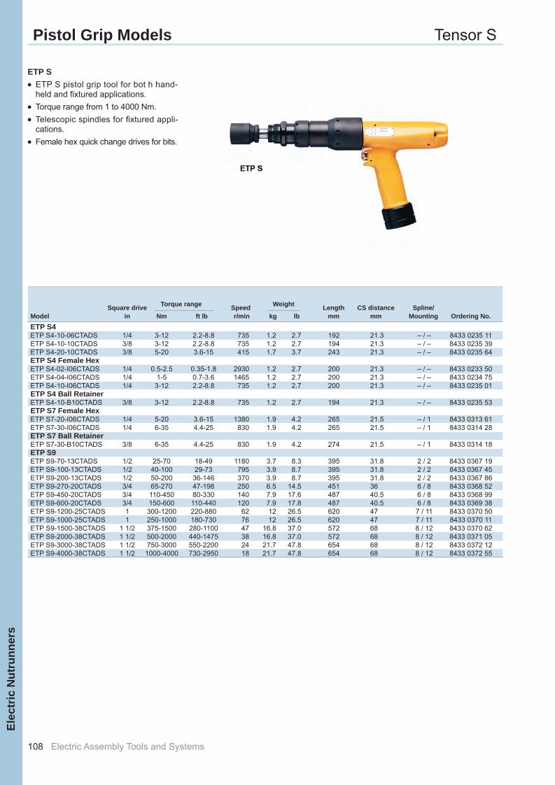
El
ectr
ic N
utru
nner
s
108 Electric Assembly Tools and Systems
Square drive Torque range Speed Weight Length CS distance Spline/ Model in Nm ft lb r/min kg lb mm mm Mounting Ordering No.ETP S4ETP S4-10-06CTADS 1/4 3-12 2.2-8.8 735 1.2 2.7 192 21.3 – / – 8433 0235 11ETP S4-10-10CTADS 3/8 3-12 2.2-8.8 735 1.2 2.7 194 21.3 – / – 8433 0235 39ETP S4-20-10CTADS 3/8 5-20 3.6-15 415 1.7 3.7 243 21.3 – / – 8433 0235 64ETP S4 Female Hex ETP S4-02-I06CTADS 1/4 0.5-2.5 0.35-1.8 2930 1.2 2.7 200 21.3 – / – 8433 0233 50ETP S4-04-I06CTADS 1/4 1-5 0.7-3.6 1465 1.2 2.7 200 21.3 – / – 8433 0234 75ETP S4-10-I06CTADS 1/4 3-12 2.2-8.8 735 1.2 2.7 200 21.3 – / – 8433 0235 01ETP S4 Ball RetainerETP S4-10-B10CTADS 3/8 3-12 2.2-8.8 735 1.2 2.7 194 21.3 – / – 8433 0235 53ETP S7 Female HexETP S7-20-I06CTADS 1/4 5-20 3.6-15 1380 1.9 4.2 265 21.5 – / 1 8433 0313 61ETP S7-30-I06CTADS 1/4 6-35 4.4-25 830 1.9 4.2 265 21.5 – / 1 8433 0314 28ETP S7 Ball RetainerETP S7-30-B10CTADS 3/8 6-35 4.4-25 830 1.9 4.2 274 21.5 – / 1 8433 0314 18ETP S9ETP S9-70-13CTADS 1/2 25-70 18-49 1180 3.7 8.3 395 31.8 2 / 2 8433 0367 19ETP S9-100-13CTADS 1/2 40-100 29-73 795 3.9 8.7 395 31.8 2 / 2 8433 0367 45ETP S9-200-13CTADS 1/2 50-200 36-146 370 3.9 8.7 395 31.8 2 / 2 8433 0367 86ETP S9-270-20CTADS 3/4 65-270 47-198 250 6.5 14.5 451 36 6 / 8 8433 0368 52ETP S9-450-20CTADS 3/4 110-450 80-330 140 7.9 17.6 487 40.5 6 / 8 8433 0368 99ETP S9-600-20CTADS 3/4 150-600 110-440 120 7.9 17.8 487 40.5 6 / 8 8433 0369 38ETP S9-1200-25CTADS 1 300-1200 220-880 62 12 26.5 620 47 7 / 11 8433 0370 50ETP S9-1000-25CTADS 1 250-1000 180-730 76 12 26.5 620 47 7 / 11 8433 0370 11ETP S9-1500-38CTADS 1 1/2 375-1500 280-1100 47 16.8 37.0 572 68 8 / 12 8433 0370 62ETP S9-2000-38CTADS 1 1/2 500-2000 440-1475 38 16.8 37.0 572 68 8 / 12 8433 0371 05ETP S9-3000-38CTADS 1 1/2 750-3000 550-2200 24 21.7 47.8 654 68 8 / 12 8433 0372 12ETP S9-4000-38CTADS 1 1/2 1000-4000 730-2950 18 21.7 47.8 654 68 8 / 12 8433 0372 55
ETP S� ETP S pistol grip tool for bot h hand-
held and fi xtured applications.� Torque range from 1 to 4000 Nm.� Telescopic spindles for fi xtured appli-
cations.� Female hex quick change drives for bits.
Pistol Grip Models Tensor S
Am_Electricnutrunner.indd 108 2012-02-06 13:17:30
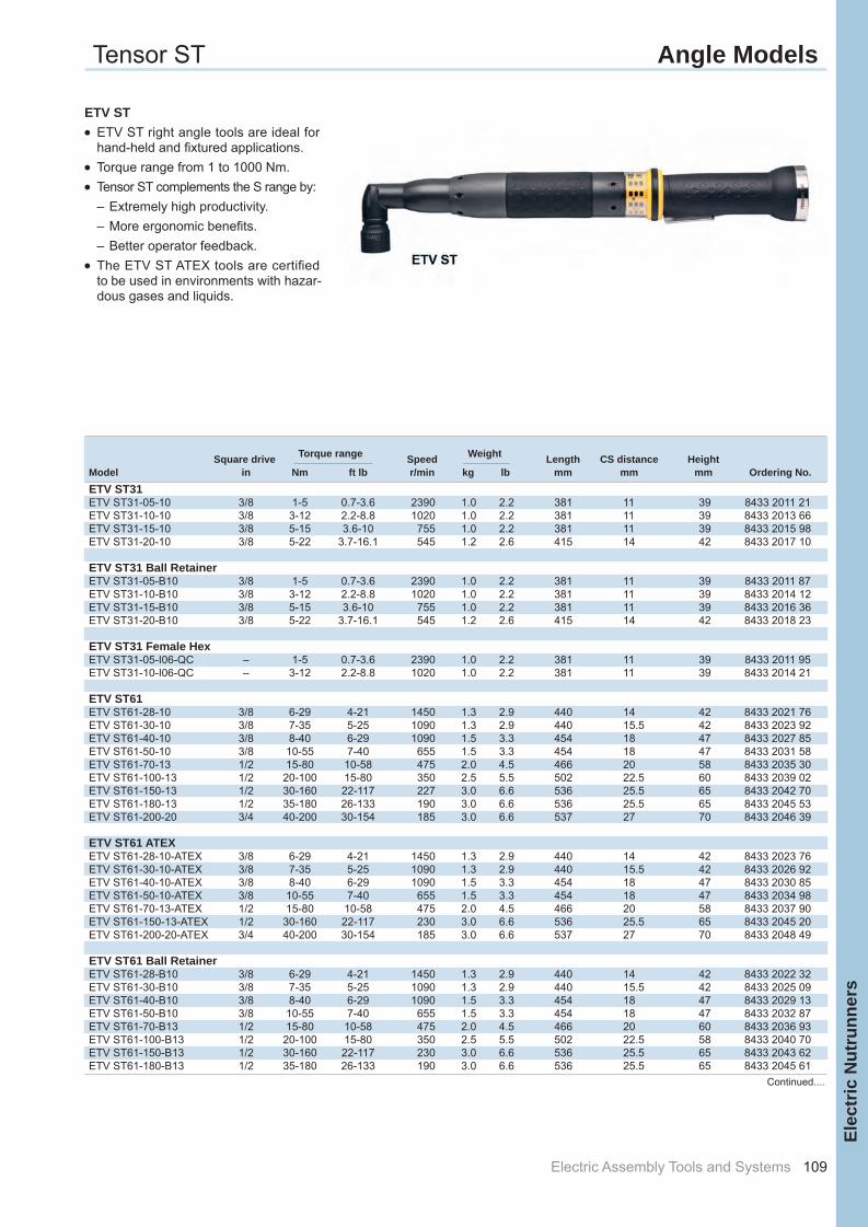
Elec
tric
Nut
runn
ers
Electric Assembly Tools and Systems 109
ETV ST� ETV ST right angle tools are ideal for
hand-held and fi xtured applications.� Torque range from 1 to 1000 Nm.� Tensor ST complements the S range by:
– Extremely high productivity.– More ergonomic benefi ts.– Better operator feedback.
� The ETV ST ATEX tools are certifi ed to be used in environments with hazar-dous gases and liquids.
Square drive Torque range Speed Weight Length CS distance Height Model in Nm ft lb r/min kg lb mm mm mm Ordering No.ETV ST31ETV ST31-05-10 3/8 1-5 0.7-3.6 2390 1.0 2.2 381 11 39 8433 2011 21ETV ST31-10-10 3/8 3-12 2.2-8.8 1020 1.0 2.2 381 11 39 8433 2013 66ETV ST31-15-10 3/8 5-15 3.6-10 755 1.0 2.2 381 11 39 8433 2015 98ETV ST31-20-10 3/8 5-22 3.7-16.1 545 1.2 2.6 415 14 42 8433 2017 10
ETV ST31 Ball RetainerETV ST31-05-B10 3/8 1-5 0.7-3.6 2390 1.0 2.2 381 11 39 8433 2011 87ETV ST31-10-B10 3/8 3-12 2.2-8.8 1020 1.0 2.2 381 11 39 8433 2014 12ETV ST31-15-B10 3/8 5-15 3.6-10 755 1.0 2.2 381 11 39 8433 2016 36ETV ST31-20-B10 3/8 5-22 3.7-16.1 545 1.2 2.6 415 14 42 8433 2018 23
ETV ST31 Female HexETV ST31-05-I06-QC – 1-5 0.7-3.6 2390 1.0 2.2 381 11 39 8433 2011 95ETV ST31-10-I06-QC – 3-12 2.2-8.8 1020 1.0 2.2 381 11 39 8433 2014 21
ETV ST61ETV ST61-28-10 3/8 6-29 4-21 1450 1.3 2.9 440 14 42 8433 2021 76ETV ST61-30-10 3/8 7-35 5-25 1090 1.3 2.9 440 15.5 42 8433 2023 92ETV ST61-40-10 3/8 8-40 6-29 1090 1.5 3.3 454 18 47 8433 2027 85ETV ST61-50-10 3/8 10-55 7-40 655 1.5 3.3 454 18 47 8433 2031 58ETV ST61-70-13 1/2 15-80 10-58 475 2.0 4.5 466 20 58 8433 2035 30ETV ST61-100-13 1/2 20-100 15-80 350 2.5 5.5 502 22.5 60 8433 2039 02ETV ST61-150-13 1/2 30-160 22-117 227 3.0 6.6 536 25.5 65 8433 2042 70ETV ST61-180-13 1/2 35-180 26-133 190 3.0 6.6 536 25.5 65 8433 2045 53ETV ST61-200-20 3/4 40-200 30-154 185 3.0 6.6 537 27 70 8433 2046 39
ETV ST61 ATEXETV ST61-28-10-ATEX 3/8 6-29 4-21 1450 1.3 2.9 440 14 42 8433 2023 76ETV ST61-30-10-ATEX 3/8 7-35 5-25 1090 1.3 2.9 440 15.5 42 8433 2026 92ETV ST61-40-10-ATEX 3/8 8-40 6-29 1090 1.5 3.3 454 18 47 8433 2030 85ETV ST61-50-10-ATEX 3/8 10-55 7-40 655 1.5 3.3 454 18 47 8433 2034 98ETV ST61-70-13-ATEX 1/2 15-80 10-58 475 2.0 4.5 466 20 58 8433 2037 90ETV ST61-150-13-ATEX 1/2 30-160 22-117 230 3.0 6.6 536 25.5 65 8433 2045 20ETV ST61-200-20-ATEX 3/4 40-200 30-154 185 3.0 6.6 537 27 70 8433 2048 49
ETV ST61 Ball RetainerETV ST61-28-B10 3/8 6-29 4-21 1450 1.3 2.9 440 14 42 8433 2022 32ETV ST61-30-B10 3/8 7-35 5-25 1090 1.3 2.9 440 15.5 42 8433 2025 09ETV ST61-40-B10 3/8 8-40 6-29 1090 1.5 3.3 454 18 47 8433 2029 13ETV ST61-50-B10 3/8 10-55 7-40 655 1.5 3.3 454 18 47 8433 2032 87ETV ST61-70-B13 1/2 15-80 10-58 475 2.0 4.5 466 20 60 8433 2036 93ETV ST61-100-B13 1/2 20-100 15-80 350 2.5 5.5 502 22.5 58 8433 2040 70ETV ST61-150-B13 1/2 30-160 22-117 230 3.0 6.6 536 25.5 65 8433 2043 62ETV ST61-180-B13 1/2 35-180 26-133 190 3.0 6.6 536 25.5 65 8433 2045 61
Continued....
Tensor ST Angle Models
Am_Electricnutrunner.indd 109 2012-02-06 13:17:31

El
ectr
ic N
utru
nner
s
110 Electric Assembly Tools and Systems
Square drive Torque range Speed Weight Length CS distance Height Model in Nm ft lb r/min kg lb mm mm mm Ordering No.ETV ST61 Flush SocketETV ST61-30-FS - 7-35 5-25 1090 1.3 2.9 440 16 32 8433 2025 50ETV ST61-40-FS - 8-40 6-29 1090 1.5 3.3 454 18 39 8433 2029 50ETV ST61-50-FS - 10-55 7-40 655 1.5 3.3 454 18 39 8433 2033 15ETV ST61-70-FS - 15-80 10-58 475 2.0 4.5 466 20 50 8433 2037 36ETV ST61-100-FS - 20-110 15-80 350 2.5 5.5 502 23 51 8433 2040 75ETV ST61-150-FS - 30-160 22-117 220 3.0 6.6 539 26 58 8433 2044 14ETV ST61-180-FS 1/2 35-180 26-133 190 3.0 6.6 539 26 58 8433 2045 72ETV ST61-200-FS - 40-200 30-154 185 3.0 6.6 541 27 58 8433 2047 21
ETV ST61 Hold & DriveETV ST61-28-HAD - 6-29 4-21 1450 1.9 4.2 463 18.3 80 8433 2023 21ETV ST61-30-HAD - 7-35 5-25 1090 1.9 4.2 463 18.3 80 8433 2026 25ETV ST61-40-HAD - 8-40 6-29 1090 2.0 4.4 440 18.3 80 8433 2030 08ETV ST61-50-HAD - 10-55 7-40 655 2.0 4.4 440 18.3 80 8433 2033 92ETV ST61-90-HAD-S - 20-95 15-70 400 2.1 4.5 522 26 80 8433 2038 25ETV ST61-120-HAD - 30-130 22-100 350 2.6 5.5 540 26 80 8433 2041 53ETV ST61-150-HAD - 30-160 22-117 220 3.1 6.6 540 26 80 8433 2044 80ETV ST61-180-HAD - 35-180 26-133 190 3.1 6.6 540 26 80 8433 2045 80ETV ST61-200-HAD - 40-200 30-154 185 3.1 6.6 541 26 80 8433 2048 27
ETV ST61 with Barcode ScannerETV ST61-28-10-BCR 3/8 6-29 4-21 1450 1.4 3.2 440 14 42 8433 2023 46ETV ST61-28-B10-BCR 3/8 6-29 4-21 1450 1.4 3.2 440 14 42 8433 2023 55ETV ST61-30-10-BCR 3/8 7-35 5-25 1090 1.4 3.2 440 15.5 42 8433 2026 66ETV ST61-30-B10-BCR 3/8 7-35 5-25 1090 1.4 3.2 440 15.5 42 8433 2026 72ETV ST61-50-10-BCR 3/8 10-55 7-40 655 1.6 3.6 454 18 47 8433 2034 67ETV ST61-50-B10-BCR 3/8 10-55 7-40 655 1.6 3.6 454 18 47 8433 2034 75ETV ST61-70-10-BCR 1/2 15-80 10-58 475 2.1 4.8 466 20 58 8433 2037 55ETV ST61-70-B10-BCR 1/2 15-80 10-58 475 2.1 4.8 466 20 58 8433 2037 61
ETV ST81ETV ST81-50-10 3/8 16-55 12-40 1090 1.8 3.9 473 18 48 8433 2051 55ETV ST81-70-13 1/2 20-80 15-58 790 2.3 5.0 485 20 58 8433 2053 48ETV ST81-100-13 1/2 20-100 15-80 540 2.7 5.9 522 22.5 60 8433 2056 82ETV ST81-150-13 1/2 30-160 22-117 380 3.2 7.0 555 26 65 8433 2060 12ETV ST81-180-13 1/2 35-180 26-133 310 3.2 7.0 555 26 65 8433 2062 31ETV ST81-200-20 3/4 40-200 30-154 300 3.2 7.0 556 27 70 8433 2063 42
ETV ST81 Ball RetainerETV ST81-50-B10 3/8 16-55 12-40 1090 1.8 3.9 473 18 48 8433 2052 36ETV ST81-70-B13 1/2 20-80 15-58 790 2.3 5.0 485 20 58 8433 2054 62ETV ST81-100-B13 1/2 20-100 15-80 540 2.7 5.9 522 22.5 60 8433 2058 24ETV ST81-150-B13 1/2 30-160 22-117 380 3.3 7.0 555 25.5 65 8433 2060 97ETV ST81-180-B13 1/2 35-180 26-133 310 3.2 7.0 555 25.5 65 8433 2062 43
ETV ST81 Flush SocketETV ST81-100-FS - 20-100 15-80 540 2.7 5.9 522 23 51 8433 2058 68ETV ST81-180-FS - 35-180 26-133 310 3.2 7.0 555 26 58 8433 2062 50ETV ST81-200-FS - 40-200 30-154 300 3.2 7.0 557 28 58 8433 2064 59
ETV ST81 Hold & DriveETV ST81-50-HAD - 16-55 12-40 1090 2.3 5.0 473 18.5 80 8433 2052 80ETV ST81-90-HAD - 20-95 15-70 665 2.4 5.1 540 26 80 8433 2056 03ETV ST81-120-HAD - 30-130 22-100 540 2.8 6.0 560 26 80 8433 2058 65ETV ST81-150-HAD - 30-160 22-117 365 3.3 7.0 560 26 80 8433 2061 81ETV ST81-180-HAD - 35-180 26-133 310 3.3 7.0 560 26 80 8433 2062 60ETV ST81-200-HAD - 40-200 30-154 300 3.3 7.0 561 28 81 8433 2065 09
ETV ST81 ExtendedETV ST81-100-13-L150 1/2 20-110 15-80 540 2.7 5.9 672 22.5 60 8433 2059 36ETV ST81-200-20-L150 3/4 40-200 30-154 300 3.2 7.0 708 27 70 8433 2065 29
ETV ST101ETV ST101-100-13 1/2 20-100 15-74 920 4.2 9.3 572 22.5 44 8433 2080 10ETV ST101-180-13-HS 1/2 50-180 37-133 575 4.2 9.3 600 25.3 47 8433 2080 52ETV ST101-200-20 3/4 50-200 37-147 485 4.4 9.7 602 27.5 47 8433 2080 92ETV ST101-270-20 3/4 65-270 48-199 380 7.3 16.1 672 32.9 62 8433 2081 23ETV ST101-370-20 3/4 90-370 66-273 280 7.3 16.1 672 32.9 62 8433 2082 26ETV ST101-450-20 3/4 110-450 81-332 230 10.6 23.4 715 54.0 76 8433 2082 81ETV ST101-600-25 1 150-600 111-443 151 10.6 23.4 715 54.0 76 8433 2083 56
Continued....
Angle Models Tensor ST
Am_Electricnutrunner.indd 110 2012-02-06 13:17:31
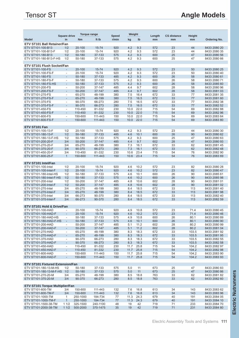
Elec
tric
Nut
runn
ers
Electric Assembly Tools and Systems 111
Square drive Torque range Speed Weight Length CS distance Height Model in Nm ft lb r/min kg lb mm mm mm Ordering No.ETV ST101 Ball Retainer/FanETV ST101-100-B13 1/2 20-100 15-74 920 4.2 9.3 572 23 44 8433 2080 20ETV ST101-100-B13-F 1/2 20-100 15-74 920 4.2 9.3 572 23 44 8433 2080 35ETV ST101-180-B13 1/2 50-180 37-133 575 4.2 9.3 600 25 47 8433 2080 56ETV ST101-180-B13-F-HS 1/2 50-180 37-133 575 4.2 9.3 600 25 47 8433 2080 66
ETV ST101 Flush Socket/FanETV ST101-100-FS - 20-100 15-74 920 4.2 9.3 572 23 50 8433 2080 25ETV ST101-100-FS-F - 20-100 15-74 920 4.2 9.3 572 23 50 8433 2080 40ETV ST101-180-FS - 50-180 37-133 485 4.2 9.3 600 26 58 8433 2080 61ETV ST101-180-FS-F - 50-180 37-133 575 4.2 9.3 600 26 58 8433 2080 71ETV ST101-180-FS-HS - 50-180 37-133 575 4.2 9.3 600 26 58 8433 2085 60ETV ST101-200-FS - 50-200 37-147 485 4.4 9.7 602 28 58 8433 2080 96ETV ST101-200-FS-F - 50-200 37-147 485 4.4 9.7 602 28 58 8433 2081 03ETV ST101-270-FS - 65-270 48-199 380 7.5 16.4 672 33 77 8433 2081 35ETV ST101-270-FS-F - 65-270 48-199 380 7.5 16.5 672 33 77 8433 2081 60ETV ST101-370-FS - 90-370 66-273 280 7.5 16.5 672 33 77 8433 2082 38ETV ST101-370-FS-F - 90-370 66-273 280 7.5 16.5 672 33 77 8433 2082 52ETV ST101-450-FS - 110-450 81-332 230 10.0 22.0 715 54 69 8433 2082 88ETV ST101-450-FS-F - 110-450 81-332 230 10.0 22.0 715 54 69 8433 2082 96ETV ST101-600-FS - 150-600 111-443 150 10.0 22.0 715 54 69 8433 2083 64ETV ST101-600-FS-F - 150-600 111-443 150 10.0 22.0 715 54 69 8433 2083 80
ETV ST101 FanETV ST101-100-13-F 1/2 20-100 15-74 920 4.2 9.3 572 23 44 8433 2080 30ETV ST101-180-13-F 1/2 50-180 37-133 485 4.6 10.1 600 26 90 8433 2080 62ETV ST101-180-13-F-HS 1/2 50-180 37-133 575 4.2 9.3 600 25 47 8433 2080 63ETV ST101-200-20-F 3/4 50-200 37-147 485 4.4 9.7 602 28 47 8433 2080 93ETV ST101-270-20-F 3/4 65-270 48-199 380 7.3 16.1 672 33 62 8433 2081 45ETV ST101-370-20-F 3/4 90-370 66-273 280 7.3 16.1 672 33 62 8433 2082 48ETV ST101-450-20-F 3/4 110-450 81-332 230 10.6 23.4 715 54 76 8433 2082 90ETV ST101-600-25-F 1 150-600 111-443 150 10.6 23.4 715 54 76 8433 2083 69
ETV ST101 Intel/FanETV ST101-100-Intel 1/2 20-100 15-74 920 4.6 10.2 572 23 82 8433 2080 28ETV ST101-100-Intel-F 1/2 20-100 15-74 920 4.6 10.2 572 23 82 8433 2080 47ETV ST101-180-Intel-HS 1/2 50-180 37-133 575 4.6 10.1 600 26 90 8433 2085 61ETV ST101-180-Intel-F-HS 1/2 50-180 37-133 575 4.6 10.2 600 26 90 8433 2085 98ETV ST101-200-Intel 1/2 50-200 37-147 485 4.8 10.6 602 28 90 8433 2081 01ETV ST101-200-Intel-F 1/2 50-200 37-147 485 4.8 10.6 602 28 90 8433 2081 02ETV ST101-270-Intel 3/4 65-270 48-199 380 8.4 18.5 672 33 113 8433 2081 40ETV ST101-270-Intel-F 3/4 65-270 48-199 380 8.4 18.5 672 33 113 8433 2081 98ETV ST101-370-Intel 3/4 66-273 90-370 280 8.4 18.5 672 33 113 8433 2082 40ETV ST101-370-Intel-F 3/4 66-273 90-370 280 8.4 18.5 672 33 113 8433 2082 59
ETV ST101 Hold & Drive/FanETV ST101-100-HAD - 20-100 15-74 920 4.9 10.8 572 23 71.4 8433 2080 45ETV ST101-100-HAD-F - 20-100 15-74 920 4.6 10.2 572 23 71.4 8433 2080 46ETV ST101-180-HAD-HS - 50-180 37-133 575 4.9 10.8 600 26 80.1 8433 2080 89ETV ST101-180-HAD-F-HS - 50-180 37-133 575 4.6 10.1 600 26 80.1 8433 2080 90ETV ST101-200-HAD - 50-200 37-147 485 5.1 11.2 602 28 80.2 8433 2080 99ETV ST101-200-HAD-F - 50-200 37-147 485 5.1 11.2 602 28 80.2 8433 2081 04ETV ST101-270-HAD - 65-270 48-199 380 8.3 18.3 672 33 103.5 8433 2081 92ETV ST101-270-HAD-F - 65-270 48-199 380 8.3 18.3 672 33 103.5 8433 2081 95ETV ST101-370-HAD - 90-370 66-273 280 8.3 18.3 672 33 103.5 8433 2082 55ETV ST101-370-HAD-F - 90-370 66-273 280 8.3 18.3 672 33 103.5 8433 2082 58ETV ST101-450-HAD - 110-450 81-332 230 11.7 25.8 715 54 104.2 8433 2082 97ETV ST101-450-HAD-F - 110-450 81-332 230 11.7 25.8 715 54 104.2 8433 2082 98ETV ST101-600-HAD - 150-600 111-443 150 11.7 25.8 715 54 104.2 8433 2083 90ETV ST101-600-HAD-F - 150-600 111-443 150 11.7 25.8 715 54 104.2 8433 2083 93
ETV ST101 Fixtured Extension/FanETV ST101-180-13-M-HS 1/2 50-180 37-133 575 5.0 11 673 25 47 8433 2080 83ETV ST101-180-13-M-F-HS 1/2 50-180 37-133 575 5.0 11 673 25 47 8433 2080 86ETV ST101-270-20-M 3/4 65-270 48-199 380 8.5 18.8 763 33 62 8433 2081 82ETV ST101-370-20-M 3/4 90-370 66-273 280 8.5 18.8 763 33 62 8433 2082 60
ETV ST101 Torque Multiplier/FanETV ST101-600-TM 3/4 150-600 111-443 132 7.6 16.8 613 34 143 8433 2083 62ETV ST101-600-TM-F 3/4 150-600 111-443 132 7.6 16.8 613 34 143 8433 2083 96ETV ST101-1000-TM 1 250-1000 184-734 77 11.3 24.3 679 40 191 8433 2084 05ETV ST101-1000-TM-F 1 250-1000 184-734 77 11.3 24.3 679 40 191 8433 2084 10ETV ST101-1500-38-TM 1 1/2 325-1500 240-1100 48 19 42 719 71 233 8433 2084 70ETV ST101-2000-38-TM 1 1/2 500-2000 370-1475 35 19 42 719 71 231 8433 2084 80
Tensor ST Angle Models
Am_Electricnutrunner.indd 111 2012-02-06 13:17:31
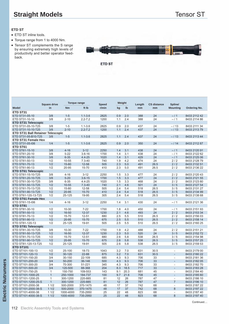
El
ectr
ic N
utru
nner
s
112 Electric Assembly Tools and Systems
ETD ST� ETD ST inline tools.� Torque range from 1 to 4000 Nm.� Tensor ST complements the S range
by ensuring extremely high levels of productivity and better operator feed-back.
Square drive Torque range Speed Weight Length CS distance Spline/ Model in Nm ft lb r/min kg lb mm mm Mounting Ordering No.ETD ST31 ETD ST31-05-10 3/8 1-5 1.1-3.6 2825 0.9 2.0 388 24 – / 1 8433 2112 42ETD ST31-10-10 3/8 2-10 2.2-7.2 1200 1.1 2.4 388 24 – / 1 8433 2114 86ETD ST31 Telescopic ETD ST31-05-10-T25 3/8 1-5 1.1-3.6 2825 0.9 2.0 437 24 – / 13 8433 2111 34ETD ST31-10-10-T25 3/8 2-10 2.2-7.2 1200 1.1 2.4 437 24 – / 13 8433 2113 79ETD ST31 Ball Retainer Telescopic ETD ST31-05-B10-T25 3/8 1-5 1.1-3.6 2825 1.1 2.4 437 24 – / 13 8433 2113 44ETD ST31 Female HexETD ST31-05-I06 1/4 1-5 1.1-3.6 2825 0.9 2.0 350 24 – / 14 8433 2112 87ETD ST61ETD ST61-15-10 3/8 4-16 3-12 2250 1.4 3.1 438 24 – / 1 8433 2120 91ETD ST61-20-10 3/8 5-22 3.6-16 1700 1.4 3.1 438 24 – / 1 8433 2122 62ETD ST61-30-10 3/8 6-35 4.4-25 1020 1.4 3.1 429 24 – / 1 8433 2125 06ETD ST61-50-13 1/2 10-55 7.3-40 740 1.9 4.2 474 24 2 / 2 8433 2128 79ETD ST61-70-13 1/2 15-80 12-58 505 2.3 5.0 491 26.5 2 / 2 8433 2132 51ETD ST61-90-13 1/2 20-95 15-70 410 2.3 5.0 491 26.5 2 / 2 8433 2136 22ETD ST61 Telescopic ETD ST61-15-10-T25 3/8 4-16 3-12 2250 1.5 3.3 477 24 2 / 2 8433 2120 43ETD ST61-20-10-T25 3/8 5-20 3.6-15 1700 1.5 3.3 477 24 2 / 2 8433 2121 55ETD ST61-30-10-T25 3/8 6-35 4.4-25 1020 1.5 3.3 468 24 2 / 2 8433 2123 80ETD ST61-50-13-T25 1/2 10-55 7.3-40 740 2.1 4.6 501 24 3 / 5 8433 2127 54ETD ST61-70-13-T25 1/2 15-80 12-58 505 2.4 5.4 518 26.5 3 / 5 8433 2131 27ETD ST61-90-13-T25 1/2 20-95 15-70 410 2.4 5.4 518 26.5 3 / 5 8433 2134 99ETD ST61-120-13-T25 1/2 25-125 19-95 305 2.4 5.4 518 26.5 3 / 5 8433 2138 68ETD ST61 Female HexETD ST61-15-I06 1/4 4-16 3-12 2250 1.4 3.1 430 24 – / 1 8433 2121 36ETD ST81ETD ST81-30-10 1/2 10-30 7-22 1700 1.8 4.0 450 24 – / 1 8433 2151 93ETD ST81-50-13 1/2 16-50 12-37 1230 2.1 4.6 493 24 2 / 2 8433 2153 34ETD ST81-70-13 1/2 15-70 12-51 880 2.5 5.5 510 26.5 2 / 2 8433 2156 03ETD ST81-90-13 1/2 20-95 15-70 675 2.5 5.5 510 26.5 2 / 2 8433 2158 14ETD ST81-120-13 1/2 25-125 19-91 505 2.5 5.5 510 26.5 2 / 2 8433 2160 25ETD ST81 Telescopic ETD ST81-30-10-T25 3/8 10-30 7-22 1700 1.9 4.2 488 24 2 / 2 8433 2151 21ETD ST81-50-13-T25 1/2 16-50 12-37 1230 2.3 5.0 520 24 3 / 5 8433 2152 72ETD ST81-70-13-T25 1/2 15-70 12-51 880 2.6 5.8 538 26.5 3 / 5 8433 2154 98ETD ST81-90-13-T25 1/2 20-95 15-70 675 2.6 5.8 538 26.5 3 / 5 8433 2157 25ETD ST81-120-13-T25 1/2 25-125 19-91 505 2.6 5.8 538 26.5 3 / 5 8433 2159 53ETD ST101ETD ST101-100-13 1/2 25-100 18-73 1043 3.2 7.0 631 30.5 - 8433 2179 00ETD ST101-120-13 1/2 30-120 22-88 875 3.2 7.0 631 30.5 - 8433 2180 22ETD ST101-150-20 3/4 30-150 22-109 685 4.3 9.3 706 33 - 8433 2181 36ETD ST101-200-20 3/4 50-200 36-146 500 4.3 9.3 706 33 - 8433 2182 05ETD ST101-300-20 3/4 70-300 51-221 345 4.3 9.3 706 33 - 8433 2182 70ETD ST101-500-20 3/4 120-500 88-368 204 8.3 18.5 717 33 - 8433 2183 28ETD ST101-750-25 1 150-750 109-553 143 9.1 20.3 681 45 - 8433 2184 40ETD ST101-1000-25 1 250-1000 184-737 100 9.7 21.6 708 45 - 8433 2185 60ETD ST101-1200-25 1 300-1200 220-885 81 12 26 787 47 - 8433 2186 10ETD ST101-1200-25-S 1 300-1200 220-885 81 12 26 787 47 7 8433 2196 10ETD ST101-2000-38 1 1/2 500-2000 370-1475 48 17 37 742 68 - 8433 2187 22ETD ST101-2000-38-S 1 1/2 500-2000 370-1475 48 17 37 742 68 8 8433 2197 22ETD ST101-4000-38 1 1/2 1000-4000 735-2950 25 22 48 823 68 - 8433 2187 40ETD ST101-4000-38-S 1 1/2 1000-4000 735-2950 25 22 48 823 68 8 8433 2197 40
Straight Models Tensor ST
Continued....
Am_Electricnutrunner.indd 112 2012-02-06 13:17:32
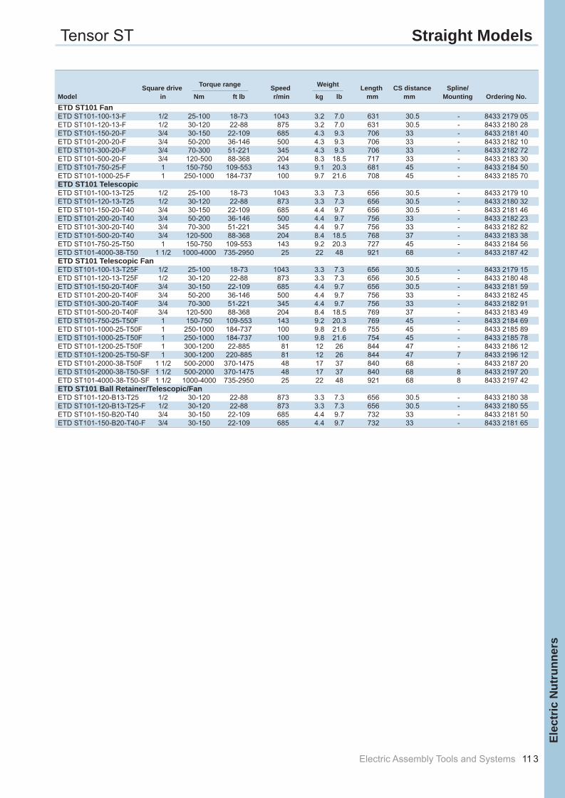
Elec
tric
Nut
runn
ers
Electric Assembly Tools and Systems 11 3
Tensor ST Straight Models
Square drive Torque range Speed Weight Length CS distance Spline/ Model in Nm ft lb r/min kg lb mm mm Mounting Ordering No.ETD ST101 FanETD ST101-100-13-F 1/2 25-100 18-73 1043 3.2 7.0 631 30.5 - 8433 2179 05ETD ST101-120-13-F 1/2 30-120 22-88 875 3.2 7.0 631 30.5 - 8433 2180 28ETD ST101-150-20-F 3/4 30-150 22-109 685 4.3 9.3 706 33 - 8433 2181 40ETD ST101-200-20-F 3/4 50-200 36-146 500 4.3 9.3 706 33 - 8433 2182 10ETD ST101-300-20-F 3/4 70-300 51-221 345 4.3 9.3 706 33 - 8433 2182 72ETD ST101-500-20-F 3/4 120-500 88-368 204 8.3 18.5 717 33 - 8433 2183 30ETD ST101-750-25-F 1 150-750 109-553 143 9.1 20.3 681 45 - 8433 2184 50ETD ST101-1000-25-F 1 250-1000 184-737 100 9.7 21.6 708 45 - 8433 2185 70ETD ST101 TelescopicETD ST101-100-13-T25 1/2 25-100 18-73 1043 3.3 7.3 656 30.5 - 8433 2179 10ETD ST101-120-13-T25 1/2 30-120 22-88 873 3.3 7.3 656 30.5 - 8433 2180 32ETD ST101-150-20-T40 3/4 30-150 22-109 685 4.4 9.7 656 30.5 - 8433 2181 46ETD ST101-200-20-T40 3/4 50-200 36-146 500 4.4 9.7 756 33 - 8433 2182 23ETD ST101-300-20-T40 3/4 70-300 51-221 345 4.4 9.7 756 33 - 8433 2182 82ETD ST101-500-20-T40 3/4 120-500 88-368 204 8.4 18.5 768 37 - 8433 2183 38ETD ST101-750-25-T50 1 150-750 109-553 143 9.2 20.3 727 45 - 8433 2184 56ETD ST101-4000-38-T50 1 1/2 1000-4000 735-2950 25 22 48 921 68 - 8433 2187 42ETD ST101 Telescopic FanETD ST101-100-13-T25F 1/2 25-100 18-73 1043 3.3 7.3 656 30.5 - 8433 2179 15ETD ST101-120-13-T25F 1/2 30-120 22-88 873 3.3 7.3 656 30.5 - 8433 2180 48ETD ST101-150-20-T40F 3/4 30-150 22-109 685 4.4 9.7 656 30.5 - 8433 2181 59ETD ST101-200-20-T40F 3/4 50-200 36-146 500 4.4 9.7 756 33 - 8433 2182 45ETD ST101-300-20-T40F 3/4 70-300 51-221 345 4.4 9.7 756 33 - 8433 2182 91ETD ST101-500-20-T40F 3/4 120-500 88-368 204 8.4 18.5 769 37 - 8433 2183 49ETD ST101-750-25-T50F 1 150-750 109-553 143 9.2 20.3 769 45 - 8433 2184 69ETD ST101-1000-25-T50F 1 250-1000 184-737 100 9.8 21.6 755 45 - 8433 2185 89ETD ST101-1000-25-T50F 1 250-1000 184-737 100 9.8 21.6 754 45 - 8433 2185 78ETD ST101-1200-25-T50F 1 300-1200 22-885 81 12 26 844 47 - 8433 2186 12ETD ST101-1200-25-T50-SF 1 300-1200 220-885 81 12 26 844 47 7 8433 2196 12ETD ST101-2000-38-T50F 1 1/2 500-2000 370-1475 48 17 37 840 68 - 8433 2187 20ETD ST101-2000-38-T50-SF 1 1/2 500-2000 370-1475 48 17 37 840 68 8 8433 2197 20ETD ST101-4000-38-T50-SF 1 1/2 1000-4000 735-2950 25 22 48 921 68 8 8433 2197 42ETD ST101 Ball Retainer/Telescopic/Fan ETD ST101-120-B13-T25 1/2 30-120 22-88 873 3.3 7.3 656 30.5 - 8433 2180 38ETD ST101-120-B13-T25-F 1/2 30-120 22-88 873 3.3 7.3 656 30.5 - 8433 2180 55ETD ST101-150-B20-T40 3/4 30-150 22-109 685 4.4 9.7 732 33 - 8433 2181 50ETD ST101-150-B20-T40-F 3/4 30-150 22-109 685 4.4 9.7 732 33 - 8433 2181 65
Am_Electricnutrunner.indd 113 2012-02-06 13:17:32
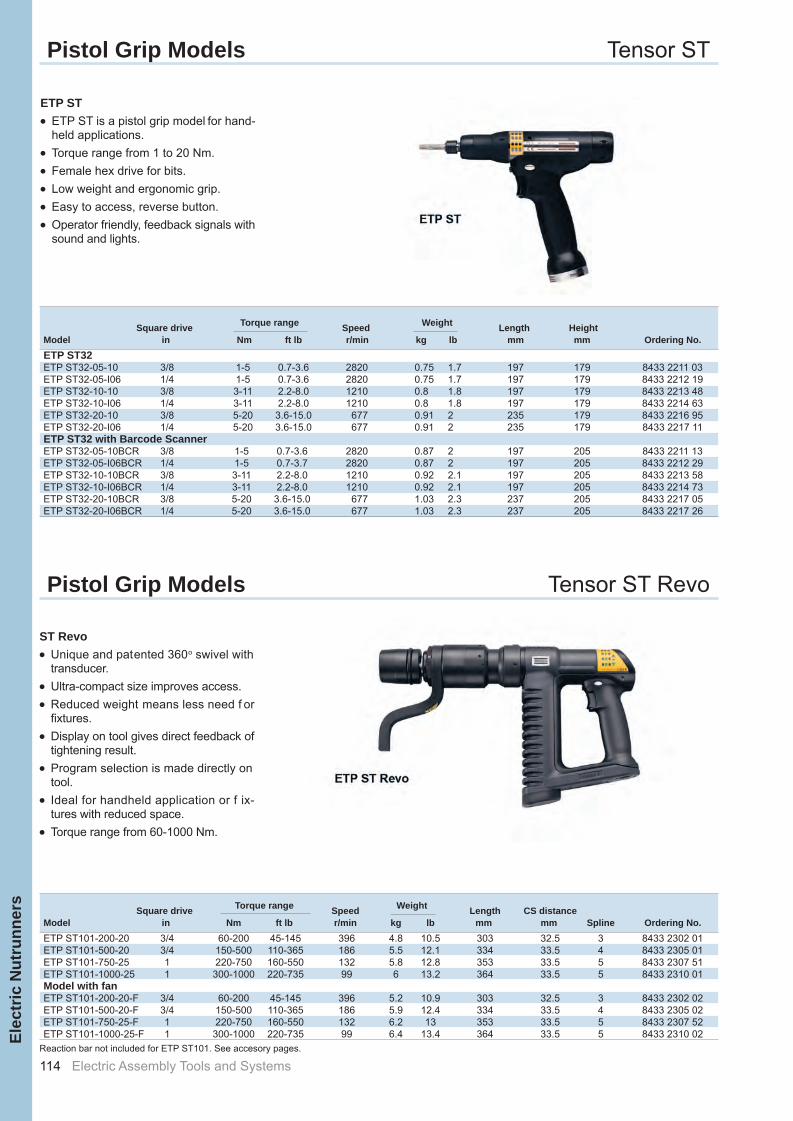
El
ectr
ic N
utru
nner
s
114 Electric Assembly Tools and Systems
Square drive Torque range Speed Weight Length Height Model in Nm ft lb r/min kg lb mm mm Ordering No.ETP ST32ETP ST32-05-10 3/8 1-5 0.7-3.6 2820 0.75 1.7 197 179 8433 2211 03ETP ST32-05-I06 1/4 1-5 0.7-3.6 2820 0.75 1.7 197 179 8433 2212 19ETP ST32-10-10 3/8 3-11 2.2-8.0 1210 0.8 1.8 197 179 8433 2213 48ETP ST32-10-I06 1/4 3-11 2.2-8.0 1210 0.8 1.8 197 179 8433 2214 63ETP ST32-20-10 3/8 5-20 3.6-15.0 677 0.91 2 235 179 8433 2216 95ETP ST32-20-I06 1/4 5-20 3.6-15.0 677 0.91 2 235 179 8433 2217 11ETP ST32 with Barcode ScannerETP ST32-05-10BCR 3/8 1-5 0.7-3.6 2820 0.87 2 197 205 8433 2211 13ETP ST32-05-I06BCR 1/4 1-5 0.7-3.7 2820 0.87 2 197 205 8433 2212 29ETP ST32-10-10BCR 3/8 3-11 2.2-8.0 1210 0.92 2.1 197 205 8433 2213 58ETP ST32-10-I06BCR 1/4 3-11 2.2-8.0 1210 0.92 2.1 197 205 8433 2214 73ETP ST32-20-10BCR 3/8 5-20 3.6-15.0 677 1.03 2.3 237 205 8433 2217 05ETP ST32-20-I06BCR 1/4 5-20 3.6-15.0 677 1.03 2.3 237 205 8433 2217 26
ETP ST� ETP ST is a pistol grip model for hand-
held applications.� Torque range from 1 to 20 Nm.� Female hex drive for bits.� Low weight and ergonomic grip.� Easy to access, reverse button.� Operator friendly, feedback signals with
sound and lights.
Pistol Grip Models Tensor ST
Square drive Torque range Speed Weight Length CS distance Model in Nm ft lb r/min kg lb mm mm Spline Ordering No.ETP ST101-200-20 3/4 60-200 45-145 396 4.8 10.5 303 32.5 3 8433 2302 01ETP ST101-500-20 3/4 150-500 110-365 186 5.5 12.1 334 33.5 4 8433 2305 01ETP ST101-750-25 1 220-750 160-550 132 5.8 12.8 353 33.5 5 8433 2307 51ETP ST101-1000-25 1 300-1000 220-735 99 6 13.2 364 33.5 5 8433 2310 01Model with fan ETP ST101-200-20-F 3/4 60-200 45-145 396 5.2 10.9 303 32.5 3 8433 2302 02ETP ST101-500-20-F 3/4 150-500 110-365 186 5.9 12.4 334 33.5 4 8433 2305 02ETP ST101-750-25-F 1 220-750 160-550 132 6.2 13 353 33.5 5 8433 2307 52ETP ST101-1000-25-F 1 300-1000 220-735 99 6.4 13.4 364 33.5 5 8433 2310 02
Pistol Grip Models Tensor ST Revo
ST Revo� Unique and patented 360o swivel with
transducer.� Ultra-compact size improves access.� Reduced weight means less need f or
fi xtures.� Display on tool gives direct feedback of
tightening result.� Program selection is made directly on
tool.� Ideal for handheld application or f ix-
tures with reduced space.� Torque range from 60-1000 Nm.
Reaction bar not included for ETP ST101. See accesory pages.
Am_Electricnutrunner.indd 114 2012-02-06 13:17:33
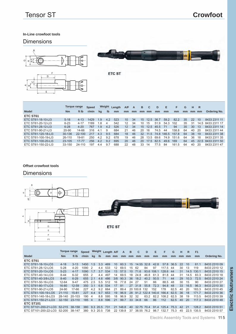
Elec
tric
Nut
runn
ers
Electric Assembly Tools and Systems 11 5
H
AF
R
G
C
D
E
F
F1
A
B
In-Line crowfoot tools
Dimensions
Tensor ST Crowfoot
Offset crowfoot tools
Dimensions
Torque range Speed Weight Length A/F A B C D E F G H R Model Nm ft lb r/min kg lb mm mm mm mm mm mm mm mm mm mm mm Ordering No.ETC ST61 ETC ST61-18-10-LI3 5-18 4-13 1429 1.9 4.2 523 10 34 15 12.5 36.7 59.2 82.2 35 22 10 8433 2311 11ETC ST61-20-12-LI3 6-23 4-17 1189 1.8 4 542 12 34 10 15 51.9 54.3 102 35 31 14.5 8433 2311 17ETC ST61-28-12-LI3 6-28 4-20 767 1.9 4.2 526 12 34 15 12.5 45.5 71 94 35 30 13 8433 2311 14ETC ST61-90-21-LI3 20-90 14-66 316 4.1 9 684 21 46 20 16 74.5 44 158.8 64 40 20 8433 2311 44ETC ST61-120-18-LI3 30-136 22-100 217 4.3 9.5 684 18 46 32 11.5 74.8 146.5 157.8 64 38 19 8433 2311 38ETC ST61-100-19-LI3 26-110 19-81 250 4.2 9.2 678 19 46 28 13.5 69.6 74.9 151.6 64 36 18 8433 2311 35ETC ST61-100-20-LI3 23-105 17-77 256 4.2 9.2 695 20 46 20 17.5 82.5 49.6 169 64 45 22.5 8433 2311 50ETC ST61-150-22-LI3 33-150 24-110 197 4.4 9.7 688 22 48 33 14 77.5 84 161.5 64 40 20 8433 2311 47
Torque range Speed Weight Length A/F A B C D E F G H R F1 Model Nm ft lb r/min kg lb mm mm mm mm mm mm mm mm mm mm mm mm Ordering No.ETC ST61 ETC ST61-18-10-LO3 4-18 3-13 1450 1.5 3.3 469 10 60.3 15 14.55 32.8 42.8 57.8 36.5 22 10 61.1 8433 2310 09ETC ST61-28-12-LO5 5-28 4-20 1090 2 4.4 533 12 69.5 15 62 84 97 117.5 44 30 13 119 8433 2310 12ETC ST61-20-13-LO5 5-23 4-17 1090 1.7 3.7 534 13 57.5 10 71.6 93.6 108.1 128.6 44 31 14.5 130.1 8433 2310 15ETC ST61-40-14-LO3 8-44 6-32 655 2 4.4 497 14 69.5 18 24.8 46.8 61.3 81.8 44 31 14.5 83.3 8433 2310 18ETC ST61-40-3/8-LO3 8-40 6-29 655 2.1 4.6 486 3/8 90.3 36 18.2 40.2 50.5 71 44 29 10.3 72.5 8433 2310 24ETC ST61-50-16-LO3 12-64 9-47 475 2.5 5.5 512 16 77.8 24 27 51 66 88.5 48 30 15 90 8433 2310 27ETC ST61-80-17-LO3 16-80 12-59 350 3.1 6.8 534 17 81 27 31.8 55.8 72.3 94.8 48 33 16.5 96.3 8433 2310 30ETC ST61-90-21-LO5 24-90 17-66 227 4.2 9.2 664 21 89.4 20 100.8 132 152 178 62.5 40 20 183.3 8433 2310 45ETC ST61-100-19-LO5 21-110 15-81 227 4.4 9.7 653 19 96.9 28 91.2 122.4 140.4 166.4 62.5 36 18 171.7 8433 2310 36ETC ST61-140-18-LO3 28-140 20-103 190 4 8.8 595 18 96.9 32 32 63.2 82.2 108.2 62.5 38 19 113.5 8433 2310 39ETC ST61-150-21-LO3 32-150 23-110 185 4 8.8 596 21 99.7 33 34.8 66 86 112 62.5 40 20 117.3 8433 2310 48ETC ST101ETC ST101-200-21-LO3 52-215 38-158 380 9.3 20.5 731 21 148.8 40 32.75 70.4 91.4 125.4 75.3 42 21 128.2 8433 2310 51ETC ST101-200-22-LO3 52-200 38-147 380 9.3 20.5 738 22 139.8 37 38.55 76.2 98.7 132.7 75.3 45 22.5 135.5 8433 2310 57
Am_Electricnutrunner.indd 115 2012-02-06 13:17:34
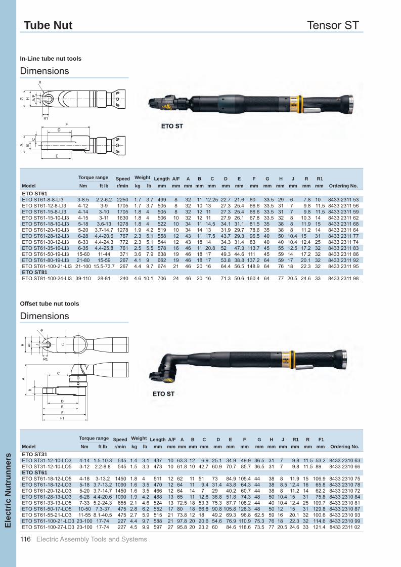
El
ectr
ic N
utru
nner
s
116 Electric Assembly Tools and Systems
R1
R
DE
FF1
C
R
H AF J G
A
B
R1
In-Line tube nut tools
Dimensions
Offset tube nut tools
Dimensions
Tube Nut Tensor ST
Torque range Speed Weight Length A/F A B C D E F G H J R R1 Model Nm ft lb r/min kg lb mm mm mm mm mm mm mm mm mm mm mm mm mm Ordering No.ETO ST61 ETO ST61-8-8-LI3 3-8.5 2.2-6.2 2250 1.7 3.7 499 8 32 11 12.25 22.7 21.6 60 33.5 29 6 7.8 10 8433 2311 53ETO ST61-12-8-LI3 4-12 3-9 1705 1.7 3.7 505 8 32 10 13 27.3 25.4 66.6 33.5 31 7 9.8 11.5 8433 2311 56ETO ST61-15-8-LI3 4-14 3-10 1705 1.8 4 505 8 32 12 11 27.3 25.4 66.6 33.5 31 7 9.8 11.5 8433 2311 59ETO ST61-15-10-LI3 4-15 3-11 1630 1.8 4 506 10 32 12 11 27.9 26.1 67.8 33.5 32 8 10.3 14 8433 2311 62ETO ST61-18-10-LI3 5-18 3.6-13 1278 1.8 4 522 10 34 11 14.5 34.1 31.1 81.5 35 38 8 11.9 15 8433 2311 68ETO ST61-20-10-LI3 5-20 3.7-14.7 1278 1.9 4.2 519 10 34 14 13 31.9 29.7 78.6 35 38 8 11.2 14 8433 2311 64ETO ST61-28-12-LI3 6-28 4.4-20.6 767 2.3 5.1 558 12 43 11 17.5 43.7 29.3 96.5 40 50 10.4 15 31 8433 2311 77ETO ST61-30-12-LI3 6-33 4.4-24.3 772 2.3 5.1 544 12 43 18 14 34.3 31.4 83 40 40 10.4 12.4 25 8433 2311 74ETO ST61-35-16-LI3 6-35 4.4-25.8 761 2.5 5.5 578 16 46 11 20.8 52 47.3 113.7 45 55 12.5 17.2 32 8433 2311 83ETO ST61-50-19-LI3 15-60 11-44 371 3.6 7.9 638 19 46 18 17 49.3 44.6 111 45 59 14 17.2 32 8433 2311 86ETO ST61-80-19-LI3 21-80 15-59 267 4.1 9 662 19 46 18 17 53.8 38.8 137.2 64 59 17 20.1 32 8433 2311 92ETO ST61-100-21-LI3 21-100 15.5-73.7 267 4.4 9.7 674 21 46 20 16 64.4 56.5 148.9 64 76 18 22.3 32 8433 2311 95ETO ST81 ETO ST81-100-24-LI3 39-110 28-81 240 4.6 10.1 706 24 46 20 16 71.3 50.6 160.4 64 77 20.5 24.6 33 8433 2311 98
Torque range Speed Weight Length A/F A B C D E F G H J R1 R F1Model Nm ft lb r/min kg lb mm mm mm mm mm mm mm mm mm mm mm mm mm mm Ordering No.ETO ST31 ETO ST31-12-10-LO3 4-14 1.5-10.3 545 1.4 3.1 437 10 63.3 12 6.9 25.1 34.9 49.9 36.5 31 7 9.8 11.5 53.2 8433 2310 63ETO ST31-12-10-LO5 3-12 2.2-8.8 545 1.5 3.3 473 10 61.8 10 42.7 60.9 70.7 85.7 36.5 31 7 9.8 11.5 89 8433 2310 66ETO ST61 ETO ST61-18-12-LO5 4-18 3-13.2 1450 1.8 4 511 12 62 11 51 73 84.9 105.4 44 38 8 11.9 15 106.9 8433 2310 75ETO ST61-18-12-LO3 5-18 3.7-13.2 1090 1.6 3.5 470 12 64 11 9.4 31.4 43.8 64.3 44 38 8.5 12.4 16 65.8 8433 2310 78ETO ST61-20-12-LO3 5-20 3.7-14.7 1450 1.6 3.5 466 12 64 14 7 29 40.2 60.7 44 38 8 11.2 14 62.2 8433 2310 72ETO ST61-28-13-LO3 6-28 4.4-20.6 1090 1.9 4.2 488 13 65 11 12.8 36.8 51.8 74.3 48 50 10.4 15 31 75.8 8433 2310 84ETO ST61-33-13-LO5 7-33 5.2-24.3 655 2.1 4.6 524 13 72.5 18 53.3 75.3 87.7 108.2 44 40 10.4 12.4 25 109.7 8433 2310 81ETO ST61-50-17-LO5 10-50 7.3-37 475 2.8 6.2 552 17 80 18 66.8 90.8 105.8 128.3 48 50 12 15 31 129.8 8433 2310 87ETO ST61-55-21-LO3 11-55 8.1-40.5 475 2.7 5.9 515 21 73.8 12 18 49.2 69.3 96.8 62.5 59 16 20.1 32 100.6 8433 2310 93ETO ST61-100-21-LO3 23-100 17-74 227 4.4 9.7 588 21 97.8 20 20.6 54.6 76.9 110.9 75.3 76 18 22.3 32 114.6 8433 2310 99ETO ST61-100-27-LO3 23-100 17-74 227 4.5 9.9 597 27 95.8 20 23.2 60 84.6 118.6 73.5 77 20.5 24.6 33 121.4 8433 2311 02
Am_Electricnutrunner.indd 116 2012-02-06 13:17:36
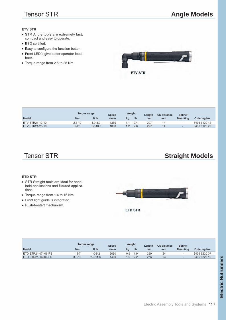
Elec
tric
Nut
runn
ers
Electric Assembly Tools and Systems 11 7
ETV STR� STR Angle tools are extremely fast,
compact and easy to operate.� ESD certifi ed. � Easy to confi gure the function button.� Front LED´s give better operator feed-
back.� Torque range from 2.5 to 25 Nm.
Torque range Speed Weight Length CS distance Spline/ Model Nm ft lb r/min kg lb mm mm Mounting Ordering No.ETV STR21-12-10 2.5-12 1.9-8.9 1350 1.1 2.4 297 14 - 8436 6120 12ETV STR21-25-10 5-25 3.7-18.5 1000 1.2 2.6 297 14 - 8436 6120 25
Tensor STR Angle Models
Tensor STR Straight Models
ETD STR� STR Straight tools are ideal for hand-
held applications and fi xtured applica-tions.
� Torque range from 1.4 to 16 Nm.� Front light guide is integrated.� Push-to-start mechanism.
Torque range Speed Weight Length CS distance Spline/ Model Nm ft lb r/min kg lb mm mm Mounting Ordering No.ETD STR21-07-I06-PS 1.5-7 1.0-5.2 2090 0.9 1.9 259 24 - 8436 6220 07ETD STR21-16-I06-PS 3.5-16 2.6-11.8 1460 1.0 2.2 276 24 - 8436 6220 16
Am_Electricnutrunner.indd 117 2012-02-06 13:17:37
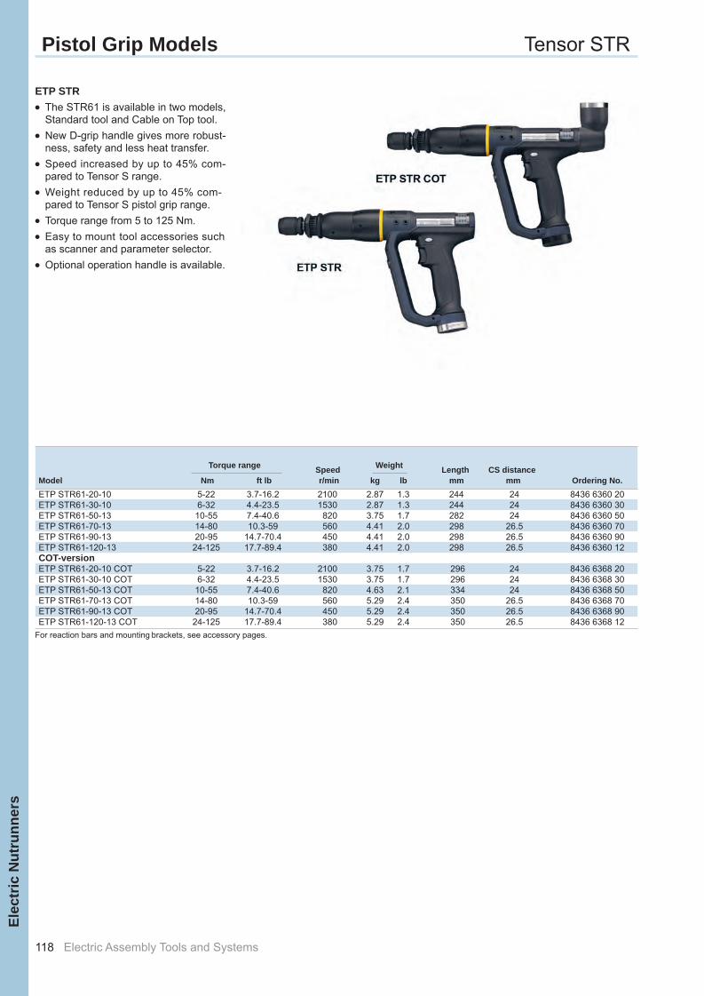
El
ectr
ic N
utru
nner
s
118 Electric Assembly Tools and Systems
Torque range Speed Weight Length CS distance Model Nm ft lb r/min kg lb mm mm Ordering No.ETP STR61-20-10 5-22 3.7-16.2 2100 2.87 1.3 244 24 8436 6360 20ETP STR61-30-10 6-32 4.4-23.5 1530 2.87 1.3 244 24 8436 6360 30ETP STR61-50-13 10-55 7.4-40.6 820 3.75 1.7 282 24 8436 6360 50ETP STR61-70-13 14-80 10.3-59 560 4.41 2.0 298 26.5 8436 6360 70ETP STR61-90-13 20-95 14.7-70.4 450 4.41 2.0 298 26.5 8436 6360 90ETP STR61-120-13 24-125 17.7-89.4 380 4.41 2.0 298 26.5 8436 6360 12COT-versionETP STR61-20-10 COT 5-22 3.7-16.2 2100 3.75 1.7 296 24 8436 6368 20ETP STR61-30-10 COT 6-32 4.4-23.5 1530 3.75 1.7 296 24 8436 6368 30ETP STR61-50-13 COT 10-55 7.4-40.6 820 4.63 2.1 334 24 8436 6368 50ETP STR61-70-13 COT 14-80 10.3-59 560 5.29 2.4 350 26.5 8436 6368 70ETP STR61-90-13 COT 20-95 14.7-70.4 450 5.29 2.4 350 26.5 8436 6368 90ETP STR61-120-13 COT 24-125 17.7-89.4 380 5.29 2.4 350 26.5 8436 6368 12
ETP STR� The STR61 is available in two models,
Standard tool and Cable on Top tool.� New D-grip handle gives more robust-
ness, safety and less heat transfer.� Speed increased by up to 45% com-
pared to Tensor S range.� Weight reduced by up to 45% com-
pared to Tensor S pistol grip range.� Torque range from 5 to 125 Nm.� Easy to mount tool accessories such
as scanner and parameter selector.� Optional operation handle is available.
Pistol Grip Models Tensor STR
For reaction bars and mounting brackets, see accessory pages.
Am_Electricnutrunner.indd 118 2012-02-06 13:17:38
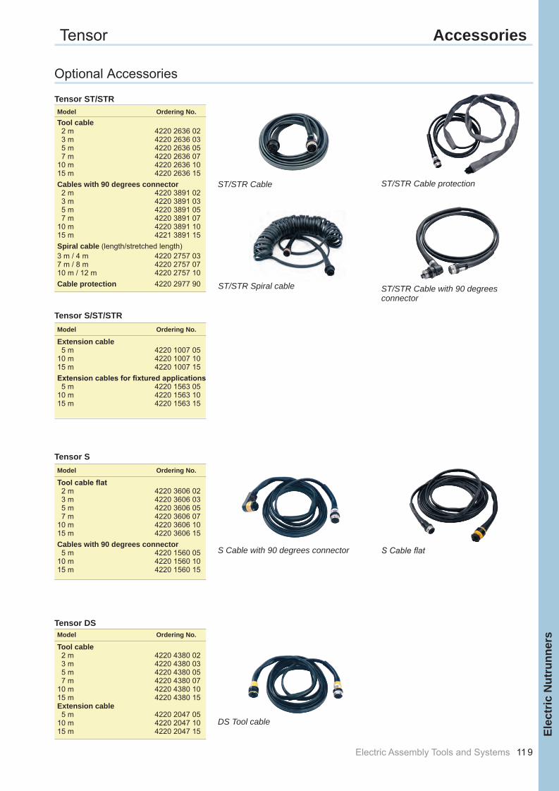
Elec
tric
Nut
runn
ers
Electric Assembly Tools and Systems 11 9
Tensor ST/STRModel Ordering No.Tool cable 2 m 4220 2636 02 3 m 4220 2636 03 5 m 4220 2636 05 7 m 4220 2636 0710 m 4220 2636 1015 m 4220 2636 15Cables with 90 degrees connector 2 m 4220 3891 02 3 m 4220 3891 03 5 m 4220 3891 05 7 m 4220 3891 0710 m 4220 3891 1015 m 4221 3891 15Spiral cable (length/stretched length)3 m / 4 m 4220 2757 037 m / 8 m 4220 2757 0710 m / 12 m 4220 2757 10Cable protection 4220 2977 90
ST/STR Cable
ST/STR Spiral cable
ST/STR Cable protection
S Cable with 90 degrees connector
Tensor SModel Ordering No.
Tool cable flat 2 m 4220 3606 02 3 m 4220 3606 03 5 m 4220 3606 05 7 m 4220 3606 0710 m 4220 3606 1015 m 4220 3606 15Cables with 90 degrees connector 5 m 4220 1560 0510 m 4220 1560 1015 m 4220 1560 15
S Cable flat
Optional Accessories
DS Tool cable
Tensor DSModel Ordering No.
Tool cable 2 m 4220 4380 02 3 m 4220 4380 03 5 m 4220 4380 05 7 m 4220 4380 0710 m 4220 4380 1015 m 4220 4380 15Extension cable 5 m 4220 2047 0510 m 4220 2047 1015 m 4220 2047 15
ST/STR Cable with 90 degreesconnector
Tensor Accessories
Tensor S/ST/STRModel Ordering No.
Extension cable 5 m 4220 1007 0510 m 4220 1007 1015 m 4220 1007 15Extension cables for fixtured applications 5 m 4220 1563 0510 m 4220 1563 1015 m 4220 1563 15
Am_Electricnutrunner.indd 119 2012-02-06 13:18:00

El
ectr
ic N
utru
nner
s
120 Electric Assembly Tools and Systems
Tool extension
Supported extensions
Reaction plate
Covers for standard socketsModel Ordering No
ETV S4/ST 28 4220 3154 03ETV S4/ST 30 4220 3154 04ETV S7/S9/ST 100 4220 3154 05ETV S7/S9/ST 150-180 4220 3154 06ETV S7/S9/ST 40-50 4220 1995 05ETV S7/S9/ST 70 4220 1993 03ETV S9/ST 200 4220 3154 07ETV S9/ST 270-370 4220 3154 08ETD S7 50-120 CTADS, ETP/ETF S7/S9 50-120, 4220 3251 00ETD S9 100, ETD ST61/81 50-120ETD S4 02/04 IO6/10CTADS, 4220 3251 01ETD S4 10 I06/10CTADS/B10CTADS, ETD S4 20 10CTADS, ETD ST61/ST81 15-30 ETD S7 20-30 4220 3251 02ETD S7 50-140 CTADST 4220 3251 02ETV ST31 20, STR21 4220 3154 03
Cover for standard sockets
Supported extensions (~154 mm)Tensor ST/STR Tensor S/DS Ordering No.STR21, ETV ST31 20, ETV S4/S7/DS2/DS7 20-30 4220 3868 90ST61 28-30ETV ST61ST81 40-50 ETV S7/S9/DS7/DS9 40-50 4220 2209 91ETV ST61/ST81 70 ETV S7/S9/DS7/DS9 70 4220 2596 91ETV ST61/81/101 150-180 4220 4125 90ETV ST61 200 ETV S7 200 4220 4125 82ETV ST81/101 200 4220 4125 91
Reaction plate for fixturing
Tool extensionsModel Length Ordering No.
ETD/ETV DS4/S4 150 4220 1131 80ETD DS7/S7 20-30 150 4220 1131 80ETV DS7/S7 30-50 150 4220 1131 80ETD/ETV DS4/S4 100 4220 1131 86ETD S7 50-120 150 4220 1132 80ETV S7 70-200 150 4220 1132 80ETF S7 50-100 150 4220 1132 80ETV S9 50 150 4220 1132 80ETD/ETV DS7 70-200 150 4220 1714 80ETD S9 200 150 4220 1132 81ETD S9 200 100 4220 1132 82ETD/ETV DS9/S9 270-370 150 4220 1585 80ETD DS9/S9 450-600 150 4220 1585 85ETV ST31 15-20 150 4220 2903 80ETV ST61 20-30 150 4220 2903 96ETV ST61 40-50 150 4220 2903 95ETV ST61 70 150 4220 2903 97ETV ST61 100-200 150 4220 2903 91
Model Ordering No.
ETV ST61 30, ETV ST61/81 200 4220 1677 91ETV ST61 40-50 4220 1677 93ETV ST61/81 70 4220 1677 95ETV ST61/81 100 4220 1678 97ETV ST61/81 150-180 4220 1678 90ETV ST10 180 4220 1677 99ETV ST10 200-600 IncludedETP ST32 20 106BCR 4220 3491 00
Accessories Tensor
Optional Accessories
Am_Electricnutrunner.indd 120 2012-02-06 13:18:07
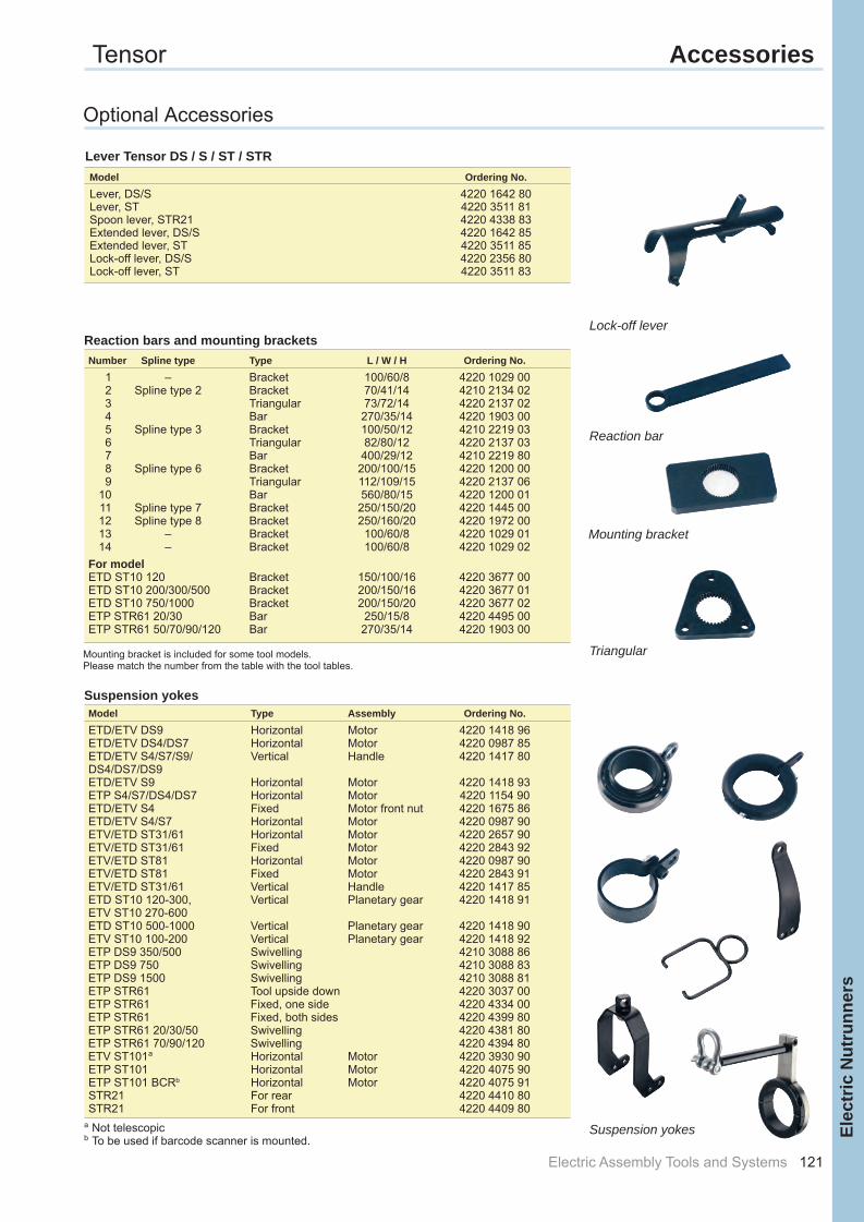
Elec
tric
Nut
runn
ers
Electric Assembly Tools and Systems 121
Tensor Accessories
Lock-off lever
Mounting bracket
Triangular
Reaction bar
Suspension yokes
Lever Tensor DS / S / ST / STR
Reaction bars and mounting brackets Number Spline type Type L / W / H Ordering No. 1 – Bracket 100/60/8 4220 1029 00 2 Spline type 2 Bracket 70/41/14 4210 2134 02 3 Triangular 73/72/14 4220 2137 02 4 Bar 270/35/14 4220 1903 00 5 Spline type 3 Bracket 100/50/12 4210 2219 03 6 Triangular 82/80/12 4220 2137 03 7 Bar 400/29/12 4210 2219 80 8 Spline type 6 Bracket 200/100/15 4220 1200 00 9 Triangular 112/109/15 4220 2137 06 10 Bar 560/80/15 4220 1200 01 11 Spline type 7 Bracket 250/150/20 4220 1445 00 12 Spline type 8 Bracket 250/160/20 4220 1972 00 13 – Bracket 100/60/8 4220 1029 01 14 – Bracket 100/60/8 4220 1029 02For modelETD ST10 120 Bracket 150/100/16 4220 3677 00ETD ST10 200/300/500 Bracket 200/150/16 4220 3677 01ETD ST10 750/1000 Bracket 200/150/20 4220 3677 02ETP STR61 20/30 Bar 250/15/8 4220 4495 00ETP STR61 50/70/90/120 Bar 270/35/14 4220 1903 00
Suspension yokesModel Type Assembly Ordering No.ETD/ETV DS9 Horizontal Motor 4220 1418 96ETD/ETV DS4/DS7 Horizontal Motor 4220 0987 85ETD/ETV S4/S7/S9/ Vertical Handle 4220 1417 80DS4/DS7/DS9 ETD/ETV S9 Horizontal Motor 4220 1418 93ETP S4/S7/DS4/DS7 Horizontal Motor 4220 1154 90ETD/ETV S4 Fixed Motor front nut 4220 1675 86ETD/ETV S4/S7 Horizontal Motor 4220 0987 90ETV/ETD ST31/61 Horizontal Motor 4220 2657 90ETV/ETD ST31/61 Fixed Motor 4220 2843 92ETV/ETD ST81 Horizontal Motor 4220 0987 90ETV/ETD ST81 Fixed Motor 4220 2843 91ETV/ETD ST31/61 Vertical Handle 4220 1417 85ETD ST10 120-300, Vertical Planetary gear 4220 1418 91ETV ST10 270-600 ETD ST10 500-1000 Vertical Planetary gear 4220 1418 90ETV ST10 100-200 Vertical Planetary gear 4220 1418 92ETP DS9 350/500 Swivelling 4210 3088 86ETP DS9 750 Swivelling 4210 3088 83ETP DS9 1500 Swivelling 4210 3088 81ETP STR61 Tool upside down 4220 3037 00ETP STR61 Fixed, one side 4220 4334 00ETP STR61 Fixed, both sides 4220 4399 80ETP STR61 20/30/50 Swivelling 4220 4381 80ETP STR61 70/90/120 Swivelling 4220 4394 80ETV ST101a Horizontal Motor 4220 3930 90ETP ST101 Horizontal Motor 4220 4075 90ETP ST101 BCRb Horizontal Motor 4220 4075 91STR21 For rear 4220 4410 80STR21 For front 4220 4409 80
a Not telescopicb To be used if barcode scanner is mounted.
Model Ordering No.Lever, DS/S 4220 1642 80Lever, ST 4220 3511 81Spoon lever, STR21 4220 4338 83Extended lever, DS/S 4220 1642 85Extended lever, ST 4220 3511 85Lock-off lever, DS/S 4220 2356 80Lock-off lever, ST 4220 3511 83
Mounting bracket is included for some tool models.Please match the number from the table with the tool tables.
Optional Accessories
Am_Electricnutrunner.indd 121 2012-02-06 13:18:23
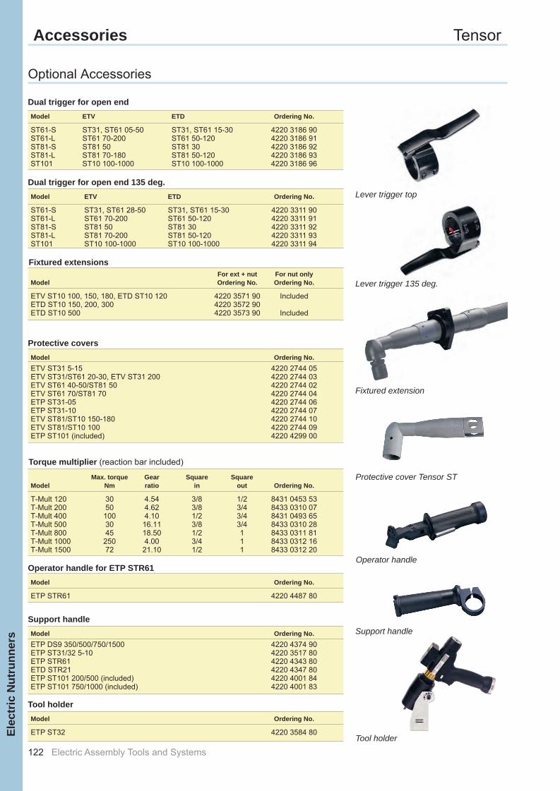
El
ectr
ic N
utru
nner
s
122 Electric Assembly Tools and Systems
Protective coversModel Ordering No.ETV ST31 5-15 4220 2744 05ETV ST31/ST61 20-30, ETV ST31 200 4220 2744 03ETV ST61 40-50/ST81 50 4220 2744 02ETV ST61 70/ST81 70 4220 2744 04ETP ST31-05 4220 2744 06ETP ST31-10 4220 2744 07ETV ST81/ST10 150-180 4220 2744 10ETV ST81/ST10 100 4220 2744 09ETP ST101 (included) 4220 4299 00
Protective cover Tensor ST
Fixtured extension
Torque multiplier (reaction bar included)
Max. torque Gear Square Square Model Nm ratio in out Ordering No.
T-Mult 120 30 4.54 3/8 1/2 8431 0453 53T-Mult 200 50 4.62 3/8 3/4 8433 0310 07T-Mult 400 100 4.10 1/2 3/4 8431 0493 65T-Mult 500 30 16.11 3/8 3/4 8433 0310 28T-Mult 800 45 18.50 1/2 1 8433 0311 81T-Mult 1000 250 4.00 3/4 1 8433 0312 16T-Mult 1500 72 21.10 1/2 1 8433 0312 20
Tool holder
Support handleModel Ordering No.ETP DS9 350/500/750/1500 4220 4374 90ETP ST31/32 5-10 4220 3517 80ETP STR61 4220 4343 80ETD STR21 4220 4347 80ETP ST101 200/500 (included) 4220 4001 84ETP ST101 750/1000 (included) 4220 4001 83
Support handle
Operator handle for ETP STR61Model Ordering No.
ETP STR61 4220 4487 80
Operator handle
Tool holderModel Ordering No.
ETP ST32 4220 3584 80
Dual trigger for open end 135 deg.Model ETV ETD Ordering No.
ST61-S ST31, ST61 28-50 ST31, ST61 15-30 4220 3311 90ST61-L ST61 70-200 ST61 50-120 4220 3311 91ST81-S ST81 50 ST81 30 4220 3311 92ST81-L ST81 70-200 ST81 50-120 4220 3311 93ST101 ST10 100-1000 ST10 100-1000 4220 3311 94
Lever trigger 135 deg.
Dual trigger for open endModel ETV ETD Ordering No.
ST61-S ST31, ST61 05-50 ST31, ST61 15-30 4220 3186 90ST61-L ST61 70-200 ST61 50-120 4220 3186 91ST81-S ST81 50 ST81 30 4220 3186 92ST81-L ST81 70-180 ST81 50-120 4220 3186 93ST101 ST10 100-1000 ST10 100-1000 4220 3186 96
Lever trigger top
Fixtured extensions For ext + nut For nut onlyModel Ordering No. Ordering No.
ETV ST10 100, 150, 180, ETD ST10 120 4220 3571 90 IncludedETD ST10 150, 200, 300 4220 3572 90ETD ST10 500 4220 3573 90 Included
Accessories Tensor
Optional Accessories
Am_Electricnutrunner.indd 122 2012-02-06 13:18:38
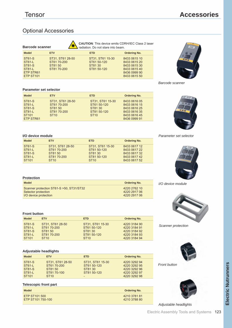
Elec
tric
Nut
runn
ers
Electric Assembly Tools and Systems 123
Tensor Accessories
Barcode scanner
Parameter set selectorModel ETV ETD Ordering No.
ST61-S ST31, ST61 28-50 ST31, ST61 15-30 8433 0616 05ST61-L ST61 70-200 ST61 50-120 8433 0616 15ST81-S ST81 50 ST81 30 8433 0616 25ST81-L ST81 70-200 ST81 50-120 8433 0616 35ST101 ST10 ST10 8433 0616 45ETP STR61 8436 0999 91
I/O device moduleModel ETV ETD Ordering No.
ST61-S ST31, ST61 28-50 ST31, ST61 15-30 8433 0617 12ST61-L ST61 70-200 ST61 50-120 8433 0617 22ST81-S ST81 50 ST81 30 8433 0617 32ST81-L ST81 70-200 ST81 50-120 8433 0617 42ST101 ST10 ST10 8433 0617 52
Parameter set selector
Barcode scanner
I/O device module
Front buttonModel ETV ETD Ordering No.
ST61-S ST31, ST61 28-50 ST31, ST61 15-30 4220 3184 90ST61-L ST61 70-200 ST61 50-120 4220 3184 91ST81-S ST81 50 ST81 30 4220 3184 92ST81-L ST81 70-200 ST81 50-120 4220 3184 93ST101 ST10 ST10 4220 3184 94
Adjustable headlights
Front button
Adjustable headlightsModel ETV ETD Ordering No.
ST61-S ST31, ST61 28-50 ST31, ST61 15-30 4220 3292 94ST61-L ST61 70-200 ST61 50-120 4220 3292 95ST81-S ST81 50 ST81 30 4220 3292 96ST81-L ST81 70-100 ST81 50-120 4220 3292 97ST101 ST10 - 4220 3292 98
ProtectionModel Ordering No.
Scanner protection ST61-S >50, ST31/ST32 4220 2762 10Selector protection 4220 2917 06I/O device protection 4220 2917 06
Scanner protection
Optional Accessories
Telescopic front partModel Ordering No.
ETP ST101 500 4210 3781 81ETP ST101 750-100 4210 3788 80
CAUTION: This device emits CDRH/IEC Class 2 laser radiation. Do not stare into beam.
Model ETV ETD Ordering No.
ST61-S ST31, ST61 28-50 ST31, ST61 15-30 8433 0615 10ST61-L ST61 70-200 ST61 50-120 8433 0615 20ST81-S ST81 50 ST81 30 8433 0615 30ST81-L ST81 70-200 ST81 50-120 8433 0615 40ETP STR61 8436 0999 90ETP ST101 8433 0615 50
Am_Electricnutrunner.indd 123 2012-02-06 13:19:00
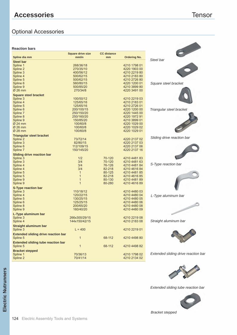
El
ectr
ic N
utru
nner
s
124 Electric Assembly Tools and Systems
Accessories Tensor
Bracket stepped
Steel bar
Square steel bracket
Triangular steel bracket
Sliding drive reaction bar
Reaction bars
S-Type reaction bar
Straight aluminum bar
L-Type aluminum bar
Extended sliding drive reaction bar
Extended sliding tube reaction bar
Square drive size CC distance Spline dia mm mm/in mm Ordering No.Steel bar Spline 1 268/36/18 4210 1798 01Spline 2 270/35/10 4220 1903 00Spline 3 400/56/12 4210 2219 80Spline 4 500/62/15 4210 2183 80Spline 5 500/62/15 4210 2726 80Spline 6 560/80/15 4220 1200 01Spline 9 500/85/20 4210 3899 80Ø 26 mm 270/34/8 4220 3491 00Square steel bracketSpline 3 100/50/12 4210 2219 03Spline 4 125/65/16 4210 2183 01Spline 5 125/65/16 4210 2726 01Spline 6 200/100/15 4220 1200 00Spline 7 250/150/20 4220 1445 00Spline 8 250/160/20 4220 1972 91Spline 9 150/85/20 4210 3899 01Ø 24 mm 100/60/8 4220 1029 00Ø 26 mm 100/60/8 4220 1029 02Ø 28 mm 100/60/8 4220 1029 01Triangular steel bracketSpline 2 73/72/14 4220 2137 02Spline 3 82/80/15 4220 2137 03Spline 6 112/109/15 4220 2137 06Spline 7 150/145/20 4220 2137 16Sliding drive reaction barSpline 3 1/2 70-120 4210 4481 83Spline 3 3/4 70-120 4210 4481 63Spline 4 3/4 76-126 4210 4481 84Spline 4 3/4 82-218 4210 4616 84Spline 5 1 80-125 4210 4481 85Spline 5 1 82-218 4210 4616 85Spline 9 1 80-130 4210 4481 89Spline 9 1 80-280 4210 4616 89S-Type reaction barSpline 3 110/18/12 4210 4480 03Spline 4 120/22/15 4210 4480 04Spline 5 130/25/15 4210 4480 05Spline 6 125/25/15 4210 4480 06Spline 8 200/65/20 4210 4480 08Spline 9 160/40/20 4210 4480 09L-Type aluminum barSpline 3 266x300/29/15 4210 2219 08Spline 4 144x150/42/15 4210 2183 08Straight aluminum barSpline 3 L = 400 4210 2219 01Extended sliding drive reaction barSpline 5 1 68-112 4210 4498 80Extended sliding tube reaction barSpline 5 1 68-112 4210 4498 82Bracket steppedSpline 1 70/36/13 4210 1798 02Spline 2 70/41/14 4210 2134 02
Optional Accessories
Am_Electricnutrunner.indd 124 2012-02-06 13:19:31
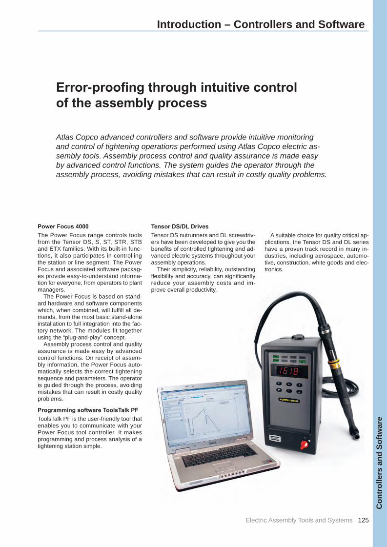
Con
trol
lers
and
Sof
twar
e
Electric Assembly Tools and Systems 125
Introduction – Controllers and Software
Error-proofing through intuitive control of the assembly process
Programming software ToolsTalk PFToolsTalk PF is the user-friendly tool that enables you to communicate with your Power Focus tool controller. It makes programming and process analysis of a tightening station simple.
Atlas Copco advanced controllers and software provide intuitive monitoring and control of tightening operations performed using Atlas Copco electric as-sembly tools. Assembly process control and quality assurance is made easy by advanced control functions. The system guides the operator through the assembly process, avoiding mistakes that can result in costly quality problems.
Power Focus 4000The Power Focus range controls tools from the Tensor DS, S, ST, STR, STB and ETX families. With its built-in func-tions, it also participates in controlling the station or line segment. The Power Focus and associated software packag-es provide easy-to-understand informa-tion for everyone, from operators to plant managers.
The Power Focus is based on stand-ard hardware and software components which, when combined, will fulfill all de-mands, from the most basic stand-alone installation to full integration into the fac-tory network. The modules fit together using the “plug-and-play” concept.
Assembly process control and quality assurance is made easy by advanced control functions. On receipt of assem-bly information, the Power Focus auto-matically selects the correct tightening sequence and parameters. The operator is guided through the process, avoiding mistakes that can result in costly quality problems.
Tensor DS/DL DrivesTensor DS nutrunners and DL screwdriv-ers have been developed to give you the benefits of controlled tightening and ad-vanced electric systems throughout your assembly operations.
Their simplicity, reliability, outstanding flexibility and accuracy, can significantly reduce your assembly costs and im-prove overall productivity.
A suitable choice for quality critical ap-plications, the Tensor DS and DL series have a proven track record in many in-dustries, including aerospace, automo-tive, construction, white goods and elec-tronics.
Am_El_contr_softw.indd 125 2012-02-06 13:31:48
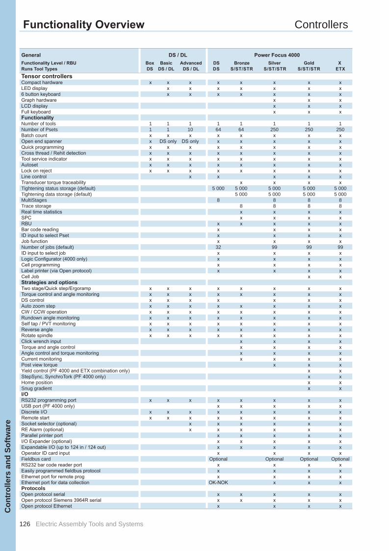
C
ontr
olle
rs a
nd S
oftw
are
126 Electric Assembly Tools and Systems
Functionality Overview Controllers
General DS / DL Power Focus 4000 Functionality Level / RBU Box Basic Advanced DS Bronze Silver Gold XRuns Tool Types DS DS / DL DS / DL DS S/ST/STR S/ST/STR S/ST/STR ETXTensor controllers Compact hardware x x x x x x x xLED display x x x x x x x6 button keyboard x x x x x x xGraph hardware x x xLCD display x x xFull keyboard x x xFunctionality Number of tools 1 1 1 1 1 1 1 1Number of Psets 1 1 10 64 64 250 250 250Batch count x x x x x x x xOpen end spanner x DS only DS only x x x x xQuick programming x x x x x x x xCross thread / Rehit detection x x x x x x x xTool service indicator x x x x x x x xAutoset x x x x x x x xLock on reject x x x x x x x xLine control x x x x xTransducer torque traceability x x x xTightening status storage (default) 5 000 5 000 5 000 5 000 5 000Tightening data storage (default) 5 000 5 000 5 000 5 000MultiStages 8 8 8 8Trace storage 8 8 8 8Real time statistics x x x xSPC x x x xRBU x x x x xBar code reading x x x xID input to select Pset x x x xJob function x x x xNumber of jobs (default) 32 99 99 99ID input to select job x x x xLogic Configurator (4000 only) x x x xCell programming x x x xLabel printer (via Open protocol) x x x xCell Job x xStrategies and options Two stage/Quick step/Ergoramp x x x x x x x xTorque control and angle monitoring x x x x x x x xDS control x x x x x x xAuto zoom step x x x x x x x xCW / CCW operation x x x x x x x xRundown angle monitoring x x x x x x x xSelf tap / PVT monitoring x x x x x x x xReverse angle x x x x x x x xRotate spindle x x x x x x x xClick wrench input x x x xTorque and angle control x x x xAngle control and torque monitoring x x x xCurrent monitoring x x x xPost view torque x x xYield control (PF 4000 and ETX combination only) x xStepSync, SynchroTork (PF 4000 only) x xHome position x xSnug gradient x xI/O RS232 programming port x x x x x x x xUSB port (PF 4000 only) x x x x xDiscrete I/O x x x x x x x xRemote start x x x x x x x xSocket selector (optional) x x x x x xRE Alarm (optional) x x x x x xParallel printer port x x x x xI/O Expander (optional) x x x x xExpandable I/O (up to 124 in / 124 out) x x x x xOperator ID card input x x x xFieldbus card Optional Optional Optional OptionalRS232 bar code reader port x x x xEasily programmed fieldbus protocol x x x xEthernet port for remote prog x x x xEthernet port for data collection OK-NOK x x xProtocols Open protocol serial x x x x xOpen protocol Siemens 3964R serial x x x x xOpen protocol Ethernet x x x x
Am_El_contr_softw.indd 126 2012-02-06 13:31:48
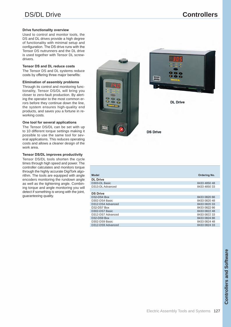
Con
trol
lers
and
Sof
twar
e
Electric Assembly Tools and Systems 127
DS/DL Drive Controllers
Drive functionality overviewUsed to control and monitor tools, the DS and DL drives provide a high degree of functionality with minimal setup and confi guration. The DS drive runs with the Tensor DS nutrunners and the DL drive is used together with Tensor DL screw-drivers.
Tensor DS and DL reduce costsThe Tensor DS and DL systems reduce costs by offering three major benefi ts:
Elimination of assembly problemsThrough its control and monitoring func-tionality, Tensor DS/DL will bring you closer to zero-fault production. By alert-ing the operator to the most common er-rors before they continue down the line, the system ensures high-quality end products, and saves you a fortune in re-working costs.
One tool for several applicationsThe Tensor DS/DL can be set with up to 10 different torque settings making it possible to use the same tool for sev-eral applications. This reduces operating costs and allows a cleaner design of the work area.
Tensor DS/DL improves productivityTensor DS/DL tools shorten the cycle times through high speed and power. The controller calculates and monitors torque through the highly accurate DigiTork algo-rithm. The tools are equipped with angle encoders monitoring the rundown angle as well as the tightening angle. Combin-ing torque and angle monitoring you will detect if something is wrong with the joint, guaranteeing quality.
Model Ordering No.DL Drive D303-DL Basic 8433 4850 48D313-DL Advanced 8433 4850 33
DS Drive D32-DS4 Box 8433 0820 66D302-DS4 Basic 8433 0820 48D312-DS4 Advanced 8433 0820 33D32-DS7 Box 8433 0822 66D302-DS7 Basic 8433 0822 48D312-DS7 Advanced 8433 0822 33D32-DS9 Box 8433 0824 66D302-DS9 Basic 8433 0824 48D312-DS9 Advanced 8433 0824 33
Am_El_contr_softw.indd 127 2012-02-06 13:31:49

C
ontr
olle
rs a
nd S
oftw
are
128 Electric Assembly Tools and Systems RBU
Advanced process control and monitoring functionsPower Focus is a modular range of con-trollers, with full flexibility, designed for applications ranging from single spindle hand-held operations to fi xtured multiple nutrunnning systems. Advanced process control and monitoring functions make it easy to view and collect data using the Internet infrastructure.� Choose your controller – either Graph
or Compact.� Choose your RBU software key to run
a tool.� Choose from various ways to use the
controller, as a stand-alone or in a net-work.
� Run many different kinds of tool, stand-ard, FS, crowfoot or open tools.
� Realtime statistics analysis.� Error-proofi ng solution.� Advanced tightening control and/or
monitoring method.� Trace view.� Logic confi gurator.� Can handle different level of communi-
cation.
Power Focus 4000 forTensor DS, S, ST, ETX, STB and STR
Model Ordering No.Power Focus 4000 W 07PF 4000-G 8433 6100 00PF 4000-C 8433 6100 05PF 4000-G-DN 8433 6140 00PF 4000-C-DN 8433 6140 05PF 4000-C-FLN 8433 6141 05PF 4000-G-PB 8433 6142 00PF 4000-C-PB 8433 6142 05PF 4000-G-IB 8433 6145 00PF 4000-C-IB 8433 6145 05PF 4000-G-MB 8433 6147 00PF 4000-C-MB 8433 6147 05PF 4000-G-EIP 8433 6149 00PF 4000-C-EIP 8433 6149 05Power Focus 4000 W 10PF 4000-G-HW 8433 7100 00PF 4000-C-HW 8433 7100 05PF 4000-G-DN- HW 8433 7140 00PF 4000-C-DN-HW 8433 7140 05PF 4000-G-FLN-HW 8433 7141 00PF 4000-C-FLN-HW 8433 7141 05PF 4000-G-PB-HW 8433 7142 00PF 4000-C-PB-HW 8433 7142 05PF 4000-G-CC-HW 8433 7143 00PF 4000-C-CC-HW 8433 7143 05PF 4000-G-IB-HW 8433 7145 00PF 4000-C-IB-HW 8433 7145 05PF 4000-G-MB-HW 8433 7147 00PF 4000-C-MB-HW 8433 7147 05PF 4000-G-PN-HW 8433 7148 00PF 4000-C-PN-HW 8433 7148 05PF 4000-G-EIP-HW 8433 7149 00PF 4000-C-EIP-HW 8433 7149 05
Controllers Power Focus 4000 series
Controller functionalityHardware key Ordering No.
RBU-Bronze 8433 0010 10RBU-Silver 8433 0015 20RBU-Gold 8433 0020 20RBU-DS 8433 0005 10RBU-X 8433 0080 20
Power Focus 4002 for Tensor SL
Model Ordering No.Power Focus 4002 W 07PF 4002-G-HW 8433 3100 00PF 4002-C-HW 8433 3100 05PF 4002-G-DN-HW 8433 3140 00PF 4002-C-DN-HW 8433 3140 05PF 4002-G-PB-HW 8433 3142 00PF 4002-C-PB-HW 8433 3142 05PF 4002-G-IB-HW 8433 3145 00PF 4002-C-IB-HW 8433 3145 05PF 4002-G-MB-HW 8433 3147 00PF 4002-C-MB-HW 8433 3147 05PF 4002-G-PN-HW 8433 3148 00PF 4002-C-PN-HW 8433 3148 05PF 4002-G-EIP-HW 8433 3149 00PF 4002-C-EIP-HW 8433 3149 05
The Power Focus 4000 is available in two versions, Compact and Graph. The difference between them is the user in-terface, where the Graph features the color display and a full keyboard.
CompactThis version offers full functionality at a lower cost, but requires a PC with the ToolsTalk PF software for process set-up.
GraphWith the Graph hardware, you have full stand-alone programming possibi-lities. When networked, the Graph can function as a programming terminal for other Power Focus units.
RBU cuts downtime Atlas Copco’s patented Rapid Backup Unit (RBU) concept transfers functiona-lity to a non-configured hardware unit, ensuring that hardware can easily be up-graded should functionality requirements change. The RBU also acts as back-up for programming and confi guration. If a change of hardware is required, just fi t the RBU to the new hardware, switch on the unit and you’re ready. All program-ming and network configurations are transferred in seconds. The RBU cuts downtime to a minimum.
IRC Focus for STwrench and Tensor STB
Model Ordering No.IRC Focus W 07IRC FOCUS-B-G-HW 8433 6500 00IRC FOCUS-B-C-HW 8433 6500 02IRC FOCUS-B-G-DN-HW 8433 6500 04IRC FOCUS-B-C-DN-HW 8433 6500 06IRC FOCUS-B-G-FLN-HW 8433 6500 08IRC FOCUS-B-C-FLN-HW 8433 6500 10IRC FOCUS-B-G-PB-HW 8433 6500 12IRC FOCUS-B-C-PB-HW 8433 6500 14IRC FOCUS-B-G-IB-HW 8433 6500 16IRC FOCUS-B-C-IB-HW 8433 6500 18IRC FOCUS-B-G-MB-HW 8433 6500 20IRC FOCUS-B-C-MB-HW 8433 6500 22IRC FOCUS-B-G-PN-HW 8433 6500 24IRC FOCUS-B-C-PN-HW 8433 6500 26IRC FOCUS-B-G-EIP-HW 8433 6500 28IRC FOCUS-B-C-EIP-HW 8433 6500 30
Am_El_contr_softw.indd 128 2012-02-06 13:31:51
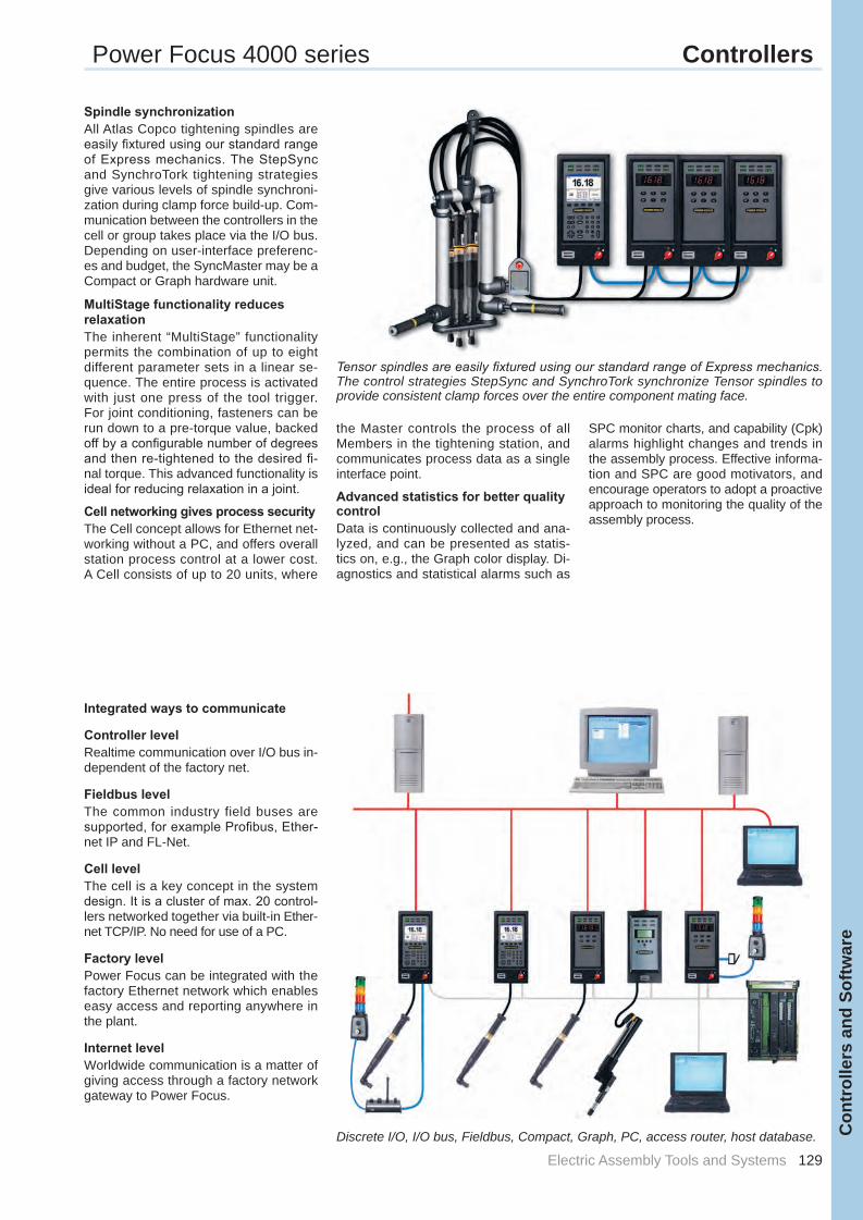
Con
trol
lers
and
Sof
twar
e
Electric Assembly Tools and Systems 129
Power Focus 4000 series Controllers
Spindle synchronizationAll Atlas Copco tightening spindles are easily fi xtured using our standard range of Express mechanics. The StepSync and SynchroTork tightening strategies give various levels of spindle synchroni-zation during clamp force build-up. Com-munication between the controllers in the cell or group takes place via the I/O bus. Depending on user-interface preferenc-es and budget, the SyncMaster may be a Compact or Graph hardware unit.
MultiStage functionality reducesrelaxationThe inherent “MultiStage” functionality permits the combination of up to eight different parameter sets in a linear se-quence. The entire process is activated with just one press of the tool trigger. For joint conditioning, fasteners can be run down to a pre-torque value, backed off by a confi gurable number of degrees and then re-tightened to the desired fi -nal torque. This advanced functionality is ideal for reducing relaxation in a joint.
Cell networking gives process securityThe Cell concept allows for Ethernet net-working without a PC, and offers overall station process control at a lower cost. A Cell consists of up to 20 units, where
the Master controls the process of all Members in the tightening station, and communicates process data as a single interface point.
Advanced statistics for better quality controlData is continuously collected and ana-lyzed, and can be presented as statis-tics on, e.g., the Graph color display. Di-agnostics and statistical alarms such as
Tensor spindles are easily fi xtured using our standard range of Express mechanics. The control strategies StepSync and SynchroTork synchronize Tensor spindles to provide consistent clamp forces over the entire component mating face.
SPC monitor charts, and capability (Cpk) alarms highlight changes and trends in the assembly process. Effective informa-tion and SPC are good motivators, and encourage operators to adopt a proactive approach to monitoring the quality of the assembly process.
Discrete I/O, I/O bus, Fieldbus, Compact, Graph, PC, access router, host database.
Integrated ways to communicate
Controller levelRealtime communication over I/O bus in-dependent of the factory net.
Fieldbus level The common industry field buses are supported, for example Profi bus, Ether-net IP and FL-Net.
Cell level The cell is a key concept in the system design. It is a cluster of max. 20 control-lers networked together via built-in Ether-net TCP/IP. No need for use of a PC.
Factory level Power Focus can be integrated with the factory Ethernet network which enables easy access and reporting anywhere in the plant.
Internet level Worldwide communication is a matter of giving access through a factory network gateway to Power Focus.
Am_El_contr_softw.indd 129 2012-02-06 13:32:01
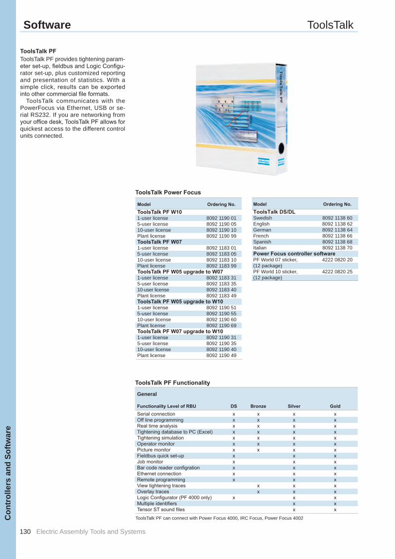
C
ontr
olle
rs a
nd S
oftw
are
130 Electric Assembly Tools and Systems
Software ToolsTalk
ToolsTalk PFToolsTalk PF provides tightening param-eter set-up, fieldbus and Logic Configu-rator set-up, plus customized reporting and presentation of statistics. With a simple click, results can be exported into other commercial file formats.
ToolsTalk communicates with the PowerFocus via Ethernet, USB or se-rial RS232. If you are networking from your office desk, ToolsTalk PF allows for quickest access to the different control units connected.
ToolsTalk PF Functionality
ToolsTalk Power Focus
Model Ordering No.ToolsTalk PF W101-user license 8092 1190 015-user license 8092 1190 0510-user license 8092 1190 10Plant license 8092 1190 99ToolsTalk PF W07 1-user license 8092 1183 015-user license 8092 1183 0510-user license 8092 1183 10Plant license 8092 1183 99ToolsTalk PF W05 upgrade to W071-user license 8092 1183 315-user license 8092 1183 3510-user license 8092 1183 40Plant license 8092 1183 49ToolsTalk PF W05 upgrade to W101-user license 8092 1190 515-user license 8092 1190 5510-user license 8092 1190 60Plant license 8092 1190 69ToolsTalk PF W07 upgrade to W101-user license 8092 1190 315-user license 8092 1190 3510-user license 8092 1190 40Plant license 8092 1190 49
Model Ordering No.ToolsTalk DS/DLSwedish 8092 1138 60English 8092 1138 62German 8092 1138 64French 8092 1138 66Spanish 8092 1138 68Italian 8092 1138 70Power Focus controller software PF World 07 sticker, 4222 0820 20(12 package)PF World 10 sticker, 4222 0820 25(12 package)
General Functionality Level of RBU DS Bronze Silver GoldSerial connection x x x xOff line programming x x x xReal time analysis x x x xTightening database to PC (Excel) x x x xTightening simulation x x x xOperator monitor x x x xPicture monitor x x x xFieldbus quick set-up x x xJob monitor x x xBar code reader configration x x xEthernet connection x x xRemote programming x x xView tightening traces x x xOverlay traces x x xLogic Configurator (PF 4000 only) x x xMultiple identifiers x xTensor ST sound files x x
ToolsTalk PF can connect with Power Focus 4000, IRC Focus, Power Focus 4002
Am_El_contr_softw.indd 130 2012-02-06 13:32:04
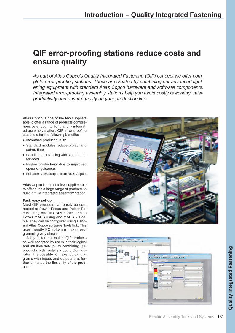
Qua
lity
Inte
grat
ed F
aste
ning
Electric Assembly Tools and Systems 131
Introduction – Quality Integrated Fastening
QIF error-proofing stations reduce costs and ensure qualityAs part of Atlas Copco’s Quality Integrated Fastening (QIF) concept we offer com-plete error proofing stations. These are created by combining our advanced tight-ening equipment with standard Atlas Copco hardware and software components. Integrated error-proofing assembly stations help you avoid costly reworking, raise productivity and ensure quality on your production line.
Atlas Copco is one of the few suppliers able to offer a range of products compre-hensive enough to build a fully integrat-ed assembly station. QIF error-proofing stations offer the following benefits:l Increased product quality.l Standard modules reduce project and
set-up time.l Fast line re-balancing with standard in-
terfaces.l Higher productivity due to improved
operator guidance.l Full after sales support from Atlas Copco.
Atlas Copco is one of a few supplier able to offer such a large range of products to build a fully integrated assembly station.
Fast, easy set-upMost QIF products can easily be con-nected to Power Focus and Pulsor Fo-cus using one I/O Bus cable, and to Power MACS using one MACS I/O ca-ble. They can be configured using stand-ard Atlas Copco software ToolsTalk. This user-friendly PC software makes pro-gramming very simple.
A key factor that makes QIF products so well accepted by users is their logical and intuitive set-up. By combining QIF products with ToolsTalk Logic Configu-rator, it is possible to make logical dia-grams with inputs and outputs that fur-ther enhance the flexibility of the prod-ucts.
Am_Qualityintfast.indd 131 2012-02-10 11:25:22

Q
ualit
y In
tegr
ated
Fas
teni
ng
132 Electric Assembly Tools and Systems132 Electric Assembly Tools and Systems
Complete Offering Quality Integrated Fastening
Selector 4, selector for Large Sockets and Operator Panel Advanced
MaxiDisplay 19 and MiniDisplay MD-01 ComNode 2 Touch with ToolsNet 4000
ESL-04 Standard and ESL-04 Compact
FeedbackHigher quality can be achieved by giving audio and/or visual feedback about the assembly process to the operators. Time and costs can be saved by reducing reworking and avoiding faulty products leaving the production line. For feedback use Atlas Copco’s Stacklights.
Variance supportProductive assembly lines demand effi cient operators. These should be supported with appropriate tools providing feedback for all actions. This will save time changing program settings and when performing reworkings in station. For variance support use Atlas Copco’s Selectors and Operator Panels.
Operator guidanceFlexible assembly lines demand different products to be as-sembled at the same station. It is possible to reduce the number of decisions taken by the operator by providing direct instructions on a screen with photos and texts of the assembly process. For operator guidance use Atlas Copco’s HMI’s (Hu-man Machine Interface).
Reducing the cost of peripherals
A complete offering
Process monitoringStoring production data for documentation and further analysis is a key factor for traceability. Process improvements can be made by analyzing data. This contributes to increasing quality and boosting productivity by minimizing the number of recalls. For process monitoring use Atlas Copco’s ToolsNet 4000.
Am_Qualityintfast.indd 132 2012-02-06 13:45:12
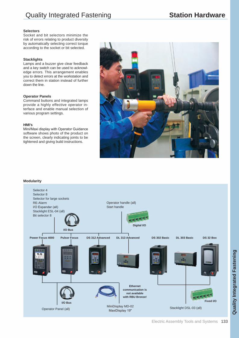
Qua
lity
Inte
grat
ed F
aste
ning
Electric Assembly Tools and Systems 133
Quality Integrated Fastening Station Hardware
SelectorsSocket and bit selectors minimize the risk of errors relating to product diversity by automatically selecting correct torque according to the socket or bit selected.
StacklightsLamps and a buzzer give clear feedback and a key switch can be used to acknowl-edge errors. This arrangement enables you to detect errors at the workstation and correct them in station instead of further down the line.
Operator PanelsCommand buttons and integrated lamps provide a highly effective operator in-terface and enable manual selection of various program settings.
HMI’sMini/Maxi display with Operator Guidance software shows photo of the product on the screen, clearly indicating joints to be tightened and giving build instructions.
Selector 4Selector 8Selector for large socketsRE-AlarmI/O Expander (all)Stacklight ESL-04 (all)Bit selector 8
MiniDisplay MD-02MaxiDisplay 19″
Stacklight DSL-03 (all)
Operator handle (all)Start handle
Ethernetcommunication is
not availablewith RBU Bronze!
Modularity
I/O Bus
Power Focus 4000 Pulsor Focus DS 312 Advanced DS 302 Basic DL 303 Basic DS 32 BoxDL 313 Advanced
Digital I/O
Fixed I/O
Operator Panel (all)
I/O Bus
Am_Qualityintfast.indd 133 2012-02-06 13:45:42

Q
ualit
y In
tegr
ated
Fas
teni
ng
134 Electric Assembly Tools and Systems
Model Ordering No.
Cables EthernetCrossed 0.5 m 4222 0682 00 1 m 4222 0682 01 3 m 4222 0682 03 5 m 4222 0682 05 10 m 4222 0682 10 15 m 4222 0682 15 25 m 4222 0682 25 50 m 4222 0682 50Straight 0.5 m 4222 0754 00 1 m 4222 0754 01 3 m 4222 0754 03 5 m 4222 0754 05 10 m 4222 0754 10 15 m 4222 0754 15 25 m 4222 0754 25 50 m 4222 0754 50
Operator panel Advanced
Selector 4
Start handle
RE-Alarm
ComNode compact
Model Ordering No.Remote StartSelector 4 8433 0610 04Selector 8 8433 0610 08Selector for large sockets 8433 0610 44Rotary selector 8433 0606 15Bit selector 8 8433 0612 08 doublea 4222 0933 92 singleb 4222 0933 91RE-Alarm 8433 0560 03
a Only compatible with Bit selector.b Only compatible with Socket selector 4 and 8.
I/O ExpandersOpen 8433 0564 39Sealed 8433 0564 45
StacklightsESL-04 Standard 8433 0570 13 Rotating red 8433 0570 30 Rotating yellow 8433 0570 35 Siren 8433 0570 40 Compact 8433 0570 16DSL-03 with push button 8433 0570 10 with blanking plugs 8433 0570 11
Operator panelAdvanced 8433 0565 00Basic 8433 0565 10
HMI’s (Human Machine Interface) MiniDisplay -2 6.5", 8435 3071 00incl. Operator GuidanceMaxiDisplay 19", 8435 3070 10incl. Operator Guidance
ComNode 2Compact 8433 2711 00Compact with ATS, 8433 2711 0110 spindle licenseCompact with I/O card 8433 2711 03Touch 8433 2711 10Touch with ATS, 8433 2711 1110 spindle licenseTouch with I/O card 8433 2711 13
Communication WEAFlex - LAN 8433 1010 00
Remote StartOperator handle (ball joint/handle)
- front/plastic 8435 3030 00- front/rubber 8435 3030 01- rear/plastic 8435 3030 02- rear/rubber 8435 3030 03
Start handle 4220 1391 91
CablesAccessory cablesI/O bus cable 0.5 m 4222 0917 00 1 m 4222 0917 01 3 m 4222 0917 03 5 m 4222 0917 05 10 m 4222 0917 10 15 m 4222 0917 15I/O Termination plug 4222 0443 00
M12-4 pinFemale - Open end 5 m 4243 0166 05Male - Female 5 m 4243 0167 05 10 m 4243 0167 10 15 m 4243 0167 15
WEAFlex (cable 1 m)Power24vDC, M12-5 pin 4243 0286 80EthernetRJ45, M12-4 pin 4222 1540 01
Station Hardware Quality Integrated Fastening
I/O expander sealed
WEAFlex
Stacklight DSL-03
Operator handle
Am_Qualityintfast.indd 134 2012-02-06 13:46:15

Qua
lity
Inte
grat
ed F
aste
ning
Electric Assembly Tools and Systems 135
Quality Integrated Fastening Station Software
ToolsNet 4000 is a data collection and process improvement software applica-tion for use with Power Focus, Pulsor Focus, PowerMACS and STWrench. Combined, these products provide total control of the assembly process, provid-ing a platform for quality improvements. Historical data, statistics and capability indexes can be accessed at any time via a standard web browser such as Mi-crosoft Internet Explorer. ToolsNet is the complete assembly process improve-ment tool.
Traceability minimizes recall costsThe production can be followed in real-time or monitored through different re-ports such as the Result List report or Product List report which provides infor-mation of every tightening related to a specifi ed period or product. In the event of warranty recalls, the result database provides access to critical information which can easily minimize the extent of any recall leading to an overnight pay-back on your investment.
HistoryFull traceability of programming chang-es. Any change that may be done on the controller will be reported to the ToolsNet database. Super users can approve or
ReportsTake the fi rst step in traceability by col-lecting all tightening results and storing them in a secure database system. Legal documentation and process improve-ments can be handled by running several pre-formatted reports specially designed to save user time and effort.
Alert Extend the usage of available informa-tion by collecting all events as they occur on the assembly line, in real time. Gen-erate reports to identify events that are happening often and trigger emails to the right personnel based on event distribu-tion rules you create. Be always on the alert for quality variation and workstations that require preventative or corrective tool maintenance.
The right solution for your needsToolsNet 4000 is divided in three differ-ent packages to cover different needs.
not approve the change and later on cross check which products were built with detailed information.
Am_Qualityintfast.indd 135 2012-02-06 13:46:23
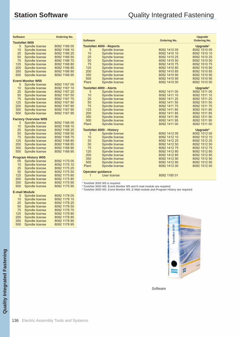
Q
ualit
y In
tegr
ated
Fas
teni
ng
136 Electric Assembly Tools and Systems
Station Software Quality Integrated Fastening
Software Ordering No.
ToolsNet W05 5 Spindle license 8092 1166 05 10 Spindle license 8092 1166 10 25 Spindle license 8092 1166 25 50 Spindle license 8092 1166 50 75 Spindle license 8092 1166 75 125 Spindle license 8092 1166 80 200 Spindle license 8092 1166 85 350 Spindle license 8092 1166 90 500 Spindle license 8092 1166 95
Event Monitor W05 5 Spindle license 8092 1167 05 10 Spindle license 8092 1167 10 25 Spindle license 8092 1167 25 50 Spindle license 8092 1167 50 75 Spindle license 8092 1167 75 125 Spindle license 8092 1167 80 200 Spindle license 8092 1167 85 350 Spindle license 8092 1167 90 500 Spindle license 8092 1167 95
Factory Overview W05 5 Spindle license 8092 1168 05 10 Spindle license 8092 1168 10 25 Spindle license 8092 1168 25 50 Spindle license 8092 1168 50 75 Spindle license 8092 1168 75 125 Spindle license 8092 1168 80 200 Spindle license 8092 1168 85 350 Spindle license 8092 1168 90 500 Spindle license 8092 1168 95
Program History W05 05 Spindle license 8092 1175 05 10 Spindle license 8092 1175 10 25 Spindle license 8092 1175 25 50 Spindle license 8092 1175 50 125 Spindle license 8092 1175 80 200 Spindle license 8092 1175 85 350 Spindle license 8092 1175 90 500 Spindle license 8092 1175 95
E-mail Module 5 Spindle license 8092 1178 05 10 Spindle license 8092 1178 10 25 Spindle license 8092 1178 25 50 Spindle license 8092 1178 50 75 Spindle license 8092 1178 75 125 Spindle license 8092 1178 80 200 Spindle license 8092 1178 85 350 Spindle license 8092 1178 90 500 Spindle license 8092 1178 95
UpgradeSoftware Ordering No. Ordering No.
ToolsNet 4000 - Reports Upgrade1 5 Spindle license 8092 1410 05 8092 1510 05 10 Spindle license 8092 1410 10 8092 1510 10 25 Spindle license 8092 1410 25 8092 1510 25 50 Spindle license 8092 1410 50 8092 1510 50 75 Spindle license 8092 1410 75 8092 1510 75 125 Spindle license 8092 1410 80 8092 1510 80 200 Spindle license 8092 1410 85 8092 1510 85 350 Spindle license 8092 1410 90 8092 1510 90 500 Spindle license 8092 1410 95 8092 1510 95 Plant Spindle license 8092 1410 00 8092 1510 00
ToolsNet 4000 - Alerts Upgrade2 5 Spindle license 8092 1411 05 8092 1511 05 10 Spindle license 8092 1411 10 8092 1511 10 25 Spindle license 8092 1411 25 8092 1511 25 50 Spindle license 8092 1411 50 8092 1511 50 75 Spindle license 8092 1411 75 8092 1511 75 125 Spindle license 8092 1411 80 8092 1511 80 200 Spindle license 8092 1411 85 8092 1511 85 350 Spindle license 8092 1411 90 8092 1511 90 500 Spindle license 8092 1411 95 8092 1511 95 Plant Spindle license 8092 1411 00 8092 1511 00
ToolsNet 4000 - History Upgrade3 5 Spindle license 8092 1412 05 8092 1512 05 10 Spindle license 8092 1412 10 8092 1512 10 25 Spindle license 8092 1412 25 8092 1512 25 50 Spindle license 8092 1412 50 8092 1512 50 75 Spindle license 8092 1412 75 8092 1512 75 125 Spindle license 8092 1412 80 8092 1512 80 200 Spindle license 8092 1412 85 8092 1512 85 350 Spindle license 8092 1412 90 8092 1512 90 500 Spindle license 8092 1412 95 8092 1512 95 Plant Spindle license 8092 1412 00 8092 1512 00
Operator guidance 1 User license 8092 1185 01
Software
1 ToolsNet 3000 W5 is required2 ToolsNet 3000 W5, Event Monitor W5 and E-mail module are required. 3 ToolsNet 3000 W5, Event Monitor W5, E-Mail module and Program History are required.
Am_Qualityintfast.indd 136 2012-02-06 13:46:24

Tool Accessories
Contents PageTPS Controller .................................. 138Torque arm SML T ............................ 141Torque arm SMS T ........................... 142Carbon arm SMC.............................. 143Linear arm SML ................................ 144MicroTorque GHP ............................. 145Torque arm accessories ................... 146Bits and power sockets..................... 150
Am_ToolAccessories.indd 137 2012-02-06 14:12:53
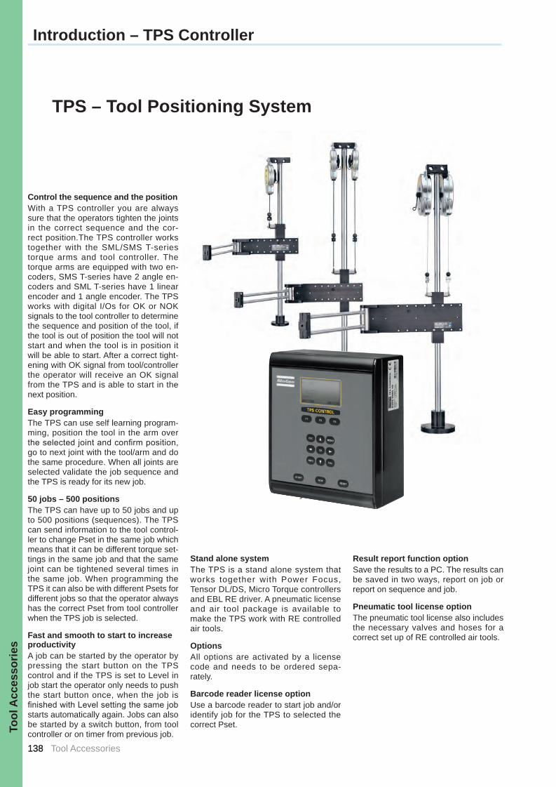
138
Tool
Acc
esso
ries
138 Tool Accessories
Introduction – TPS Controller
TPS – Tool Positioning System
Control the sequence and the positionWith a TPS controller you are always sure that the operators tighten the joints in the correct sequence and the cor-rect position.The TPS controller works together with the SML/SMS T-series torque arms and tool controller. The torque arms are equipped with two en-coders, SMS T-series have 2 angle en-coders and SML T-series have 1 linear encoder and 1 angle encoder. The TPS works with digital I/Os for OK or NOK signals to the tool controller to determine the sequence and position of the tool, if the tool is out of position the tool will not start and when the tool is in position it will be able to start. After a correct tight-ening with OK signal from tool/controller the operator will receive an OK signal from the TPS and is able to start in the next position.
Easy programmingThe TPS can use self learning program-ming, position the tool in the arm over theselectedjointandconfirmposition,go to next joint with the tool/arm and do the same procedure. When all joints are selected validate the job sequence and the TPS is ready for its new job.
50 jobs – 500 positionsThe TPS can have up to 50 jobs and up to 500 positions (sequences). The TPS can send information to the tool control-ler to change Pset in the same job which means that it can be different torque set-tings in the same job and that the same joint can be tightened several times in the same job. When programming the TPS it can also be with different Psets for different jobs so that the operator always has the correct Pset from tool controller when the TPS job is selected.
Fast and smooth to start to increase productivityA job can be started by the operator by pressing the start button on the TPS control and if the TPS is set to Level in job start the operator only needs to push the start button once, when the job is finishedwithLevelsettingthesamejobstarts automatically again. Jobs can also be started by a switch button, from tool controller or on timer from previous job.
Stand alone systemThe TPS is a stand alone system that works together with Power Focus, Tensor DL/DS, Micro Torque controllers and EBL RE driver. A pneumatic license and air tool package is available to make the TPS work with RE controlled air tools.
OptionsAll options are activated by a license code and needs to be ordered sepa-rately.
Barcode reader license optionUse a barcode reader to start job and/or identify job for the TPS to selected the correct Pset.
Result report function optionSave the results to a PC. The results can be saved in two ways, report on job or report on sequence and job.
Pneumatic tool license optionThe pneumatic tool license also includes the necessary valves and hoses for a correct set up of RE controlled air tools.
Am_ToolAccessories.indd 138 2012-02-06 14:13:00

139
Tool
Acc
esso
ries
Tool Accessories 139
Model Ordering No.Barcode license 4390 2045 00Pneumatic license 4390 2046 00Reporting license 4390 2047 00
Model Ordering No.TPS Controller 8202 9004 10Torque arms with encodersSML T-5 Position 4390 2030 00SML T-12 Position 4390 2031 00SML T-25 Position 4390 2032 00SML T-50 Position 4390 2034 00SML T-100 Position 4390 2035 00SMS T-5 Position 4390 2036 00SMS T-12 Position 4390 2037 00SMS T-25 Position 4390 2038 00SMS T-50 Position 4390 2039 00SMS T-100 Position 4390 2040 00
Model Ordering No.Cable TPS to controller Power Focus/Tensor9.8 ft 4222 1715 0332.8 ft 4222 1715 10Cable TPS to EBL RE driver4.9 ft 4222 1733 019.8 ft 4222 1733 03Cable TPS to controller G44.9 ft 4222 1734 019.8 ft 4222 1734 03Cable TPS to controller MTF4004.9 ft 4222 1735 019.8 ft 4222 1735 03TPS Open End cable9.8 ft 4222 1743 0332.8 ft 4222 1743 10
TPS Controller
TPS Controller – Control the sequence and the positionWith a TPS controller you are always sure that the operator tighten the joints in the correct sequence and in the correct position.l 50 jobs and 500 positions available.l OK/NOK signal on position.l The tool will not start when it is out of
position.l Batch count together with OK/NOK on
position.l Works together with Atlas Copco elec-
tric tools and RE controlled pneumatic tools.
l Possibility to save and upload set up through a PC.
l Easy and fast set up and program-ming.
l Errorproofingsolution.l ESD approved.
Model Ordering No.Power supply 24VDC 30W 4222 1728 50Power cordEU 4222 1371 02US 4222 1372 02UK 4222 1373 02India 4222 1374 02Switzerland 4222 1375 02Italy 4222 1376 02Australia 4222 1377 02Denmark 4222 1378 02
How to order
1. TPS Controller
2. Select positioning torque arm by style (linear or swivel) and torque arm capacity
3. Cable TPS to tool controller
4. Power supply - optional. (Order power cord separately)
5. Select other options if applicable
TPS Controller Options
Cables Power supply/cord
Tool holder is ordered separately.
Am_ToolAccessories.indd 139 2012-02-06 14:13:05
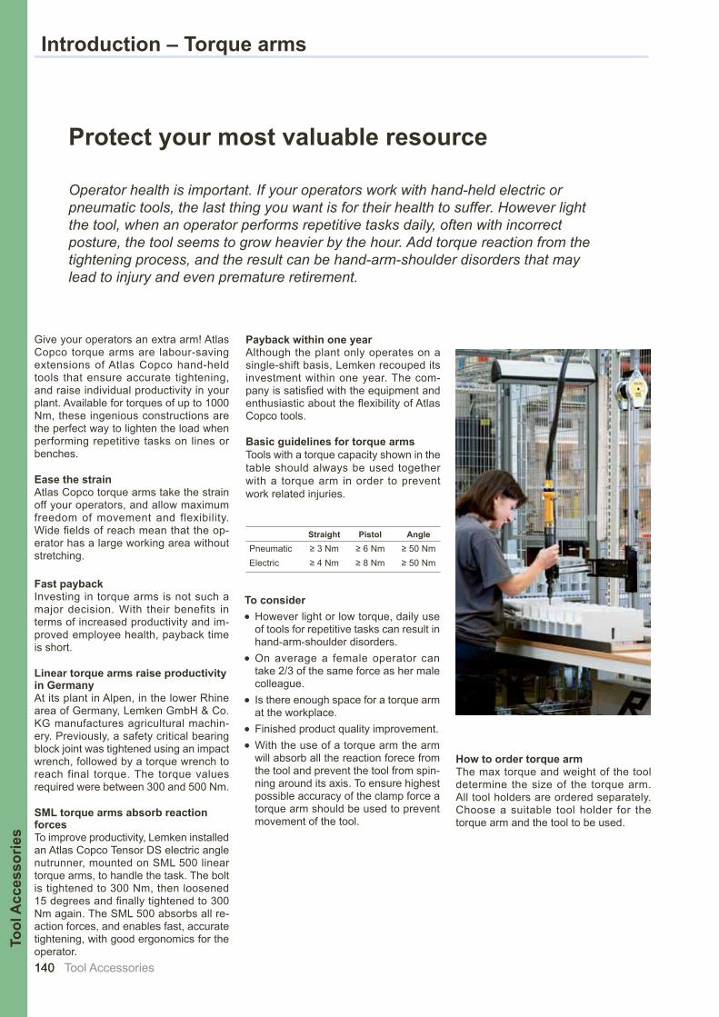
140
Tool
Acc
esso
ries
140 Tool Accessories
Introduction – Torque arms
Protect your most valuable resource
Operator health is important. If your operators work with hand-held electric or pneumatic tools, the last thing you want is for their health to suffer. However light the tool, when an operator performs repetitive tasks daily, often with incorrect posture, the tool seems to grow heavier by the hour. Add torque reaction from the tightening pro cess, and the result can be hand-arm-shoulder disorders that may lead to injury and even premature retirement.
Payback within one yearAlthough the plant only operates on a single-shift basis, Lemken recouped its investment within one year. The com-pany is satisfied with the equipment and enthusiastic about the flexibility of Atlas Copco tools.
Basic guidelines for torque armsTools with a torque capacity shown in the table should always be used together with a torque arm in order to prevent work related injuries.
To considerl However light or low torque, daily use
of tools for repetitive tasks can result in hand-arm-shoulder disorders.
l On average a female operator can take 2/3 of the same force as her male colleague.
l Is there enough space for a torque arm at the workplace.
l Finished product quality improvement.l With the use of a torque arm the arm
will absorb all the reaction forece from the tool and prevent the tool from spin-ning around its axis. To ensure highest possible accuracy of the clamp force a torque arm should be used to prevent movement of the tool.
Give your operators an extra arm! Atlas Copco torque arms are labour-saving extensions of Atlas Copco hand-held tools that ensure accurate tightening, and raise individual productivity in your plant. Available for torques of up to 1000 Nm, these ingenious constructions are the perfect way to lighten the load when performing repetitive tasks on lines or benches.
Ease the strainAtlas Copco torque arms take the strain off your operators, and allow maximum freedom of movement and flexibility. Wide fields of reach mean that the op-erator has a large working area without stretching.
Fast paybackInvesting in torque arms is not such a major decision. With their benefits in terms of increased productivity and im-proved employee health, payback time is short.
Linear torque arms raise productivity in GermanyAt its plant in Alpen, in the lower Rhine area of Germany, Lemken GmbH & Co. KG manufactures agricultural machin-ery. Previously, a safety critical bearing block joint was tightened using an impact wrench, followed by a torque wrench to reach final torque. The torque values required were between 300 and 500 Nm.
SML torque arms absorb reaction forcesTo improve productivity, Lemken installed an Atlas Copco Tensor DS electric angle nutrunner, mounted on SML 500 linear torque arms, to handle the task. The bolt is tightened to 300 Nm, then loosened 15 degrees and finally tightened to 300 Nm again. The SML 500 absorbs all re-action forces, and enables fast, accurate tightening, with good ergonomics for the operator.
Straight Pistol AnglePneumatic ≥ 3 Nm ≥ 6 Nm ≥ 50 NmElectric ≥ 4 Nm ≥ 8 Nm ≥ 50 Nm
How to order torque armThe max torque and weight of the tool determine the size of the torque arm. All tool holders are ordered separately. Choose a suitable tool holder for the torque arm and the tool to be used.
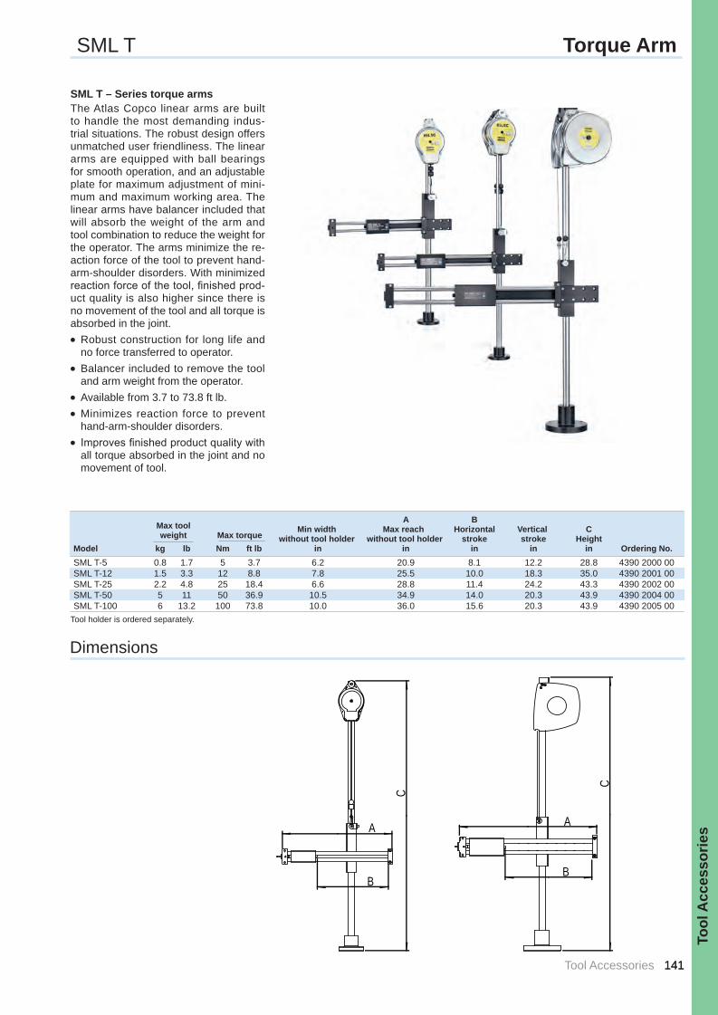
141
Tool
Acc
esso
ries
Tool Accessories 141
C
A
B
C
A
B
SML T Torque Arm
SML T – Series torque armsThe Atlas Copco linear arms are built to handle the most demanding indus-trial situations. The robust design offers unmatched user friendliness. The linear arms are equipped with ball bearings for smooth operation, and an adjustable plate for maximum adjustment of mini-mum and maximum working area. The linear arms have balancer included that will absorb the weight of the arm and tool combination to reduce the weight for the operator. The arms minimize the re-action force of the tool to prevent hand-arm-shoulder disorders. With minimized reactionforceofthetool,finishedprod-uct quality is also higher since there is no movement of the tool and all torque is absorbed in the joint. l Robust construction for long life and
no force transferred to operator.l Balancer included to remove the tool
and arm weight from the operator.l Available from 3.7 to 73.8 ft lb. l Minimizes reaction force to prevent
hand-arm-shoulder disorders.l Improvesfinishedproductqualitywith
all torque absorbed in the joint and no movement of tool.
A B Max tool Min width Max reach Horizontal vertical C weight Max torque without tool holder without tool holder stroke stroke Height Model kg lb Nm ft lb in in in in in Ordering No.SML T-5 0.8 1.7 5 3.7 6.2 20.9 8.1 12.2 28.8 4390 2000 00SML T-12 1.5 3.3 12 8.8 7.8 25.5 10.0 18.3 35.0 4390 2001 00SML T-25 2.2 4.8 25 18.4 6.6 28.8 11.4 24.2 43.3 4390 2002 00SML T-50 5 11 50 36.9 10.5 34.9 14.0 20.3 43.9 4390 2004 00SML T-100 6 13.2 100 73.8 10.0 36.0 15.6 20.3 43.9 4390 2005 00
Dimensions
Tool holder is ordered separately.
Am_ToolAccessories.indd 141 2012-02-06 14:13:36
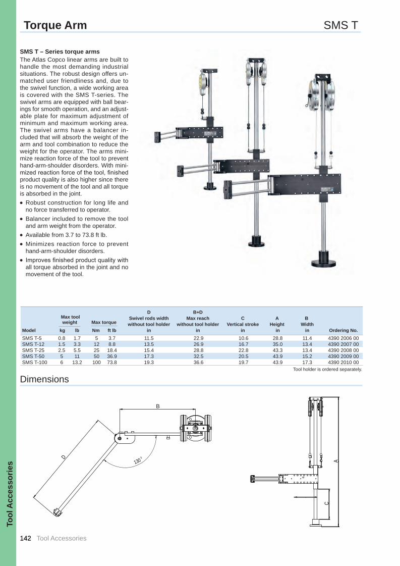
142
Tool
Acc
esso
ries
142 Tool Accessories
1300D
B
CA
SMS T – Series torque armsThe Atlas Copco linear arms are built to handle the most demanding industrial situations. The robust design offers un-matched user friendliness and, due to the swivel function, a wide working area is covered with the SMS T-series. The swivel arms are equipped with ball bear-ings for smooth operation, and an adjust-able plate for maximum adjustment of minimum and maximum working area. The swivel arms have a balancer in-cluded that will absorb the weight of the arm and tool combination to reduce the weight for the operator. The arms mini-mize reaction force of the tool to prevent hand-arm-shoulder disorders. With mini-mizedreactionforceofthetool,finishedproduct quality is also higher since there is no movement of the tool and all torque is absorbed in the joint.l Robust construction for long life and
no force transferred to operator.l Balancer included to remove the tool
and arm weight from the operator.l Available from 3.7 to 73.8 ft lb.l Minimizes reaction force to prevent
hand-arm-shoulder disorders.l Improvesfinishedproductqualitywith
all torque absorbed in the joint and no movement of the tool.
D B+D Max tool Swivel rods width Max reach C A B weight Max torque without tool holder without tool holder vertical stroke Height width Model kg lb Nm ft lb in in in in in Ordering No.SMS T-5 0.8 1.7 5 3.7 11.5 22.9 10.6 28.8 11.4 4390 2006 00SMS T-12 1.5 3.3 12 8.8 13.5 26.9 16.7 35.0 13.4 4390 2007 00SMS T-25 2.5 5.5 25 18.4 15.4 28.8 22.8 43.3 13.4 4390 2008 00SMS T-50 5 11 50 36.9 17.3 32.5 20.5 43.9 15.2 4390 2009 00SMS T-100 6 13.2 100 73.8 19.3 36.6 19.7 43.9 17.3 4390 2010 00
DimensionsTool holder is ordered separately.
Torque Arm SMS T
Am_ToolAccessories.indd 142 2012-02-06 14:13:38
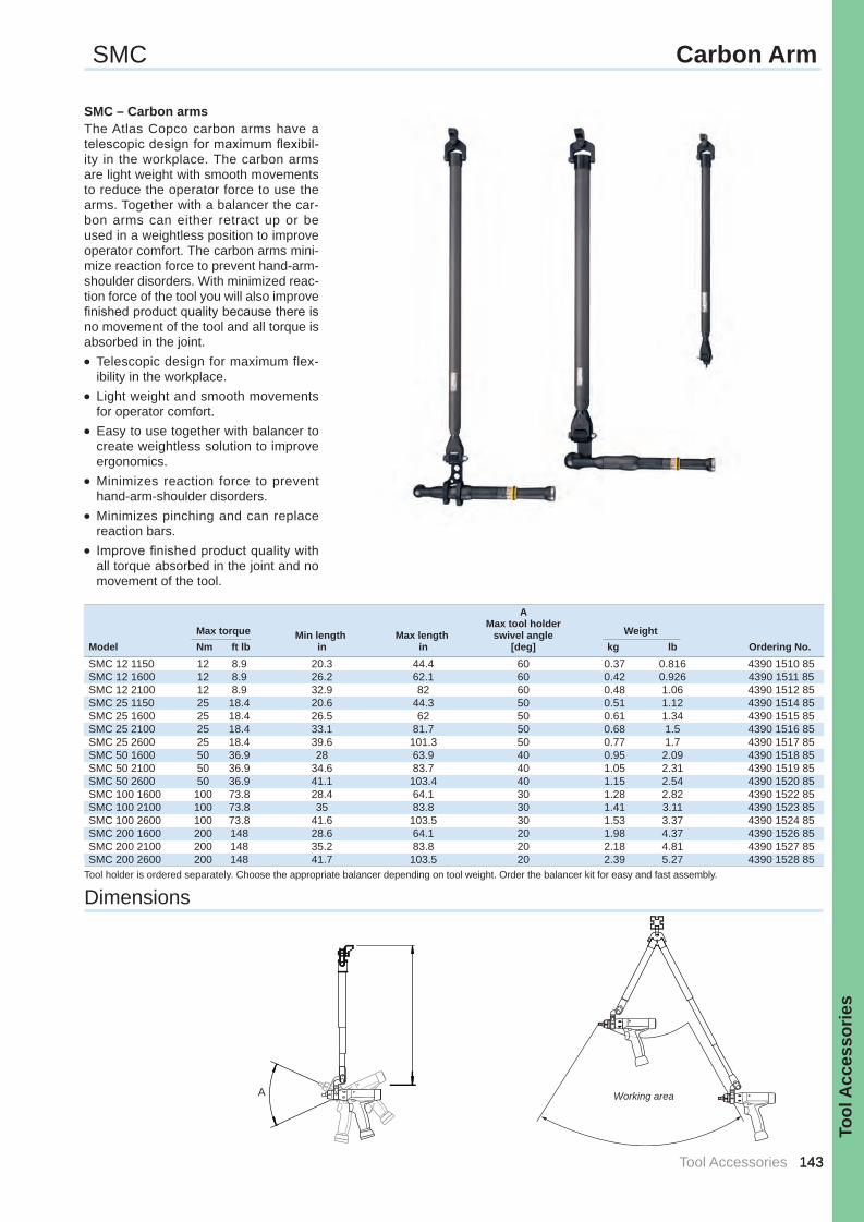
143
Tool
Acc
esso
ries
Tool Accessories 143
A
A
SMC Carbon Arm
Dimensions
A Max tool holder Max torque Min length Max length swivel angle weight Model Nm ft lb in in [deg] kg lb Ordering No.SMC 12 1150 12 8.9 20.3 44.4 60 0.37 0.816 4390 1510 85SMC 12 1600 12 8.9 26.2 62.1 60 0.42 0.926 4390 1511 85SMC 12 2100 12 8.9 32.9 82 60 0.48 1.06 4390 1512 85SMC 25 1150 25 18.4 20.6 44.3 50 0.51 1.12 4390 1514 85SMC 25 1600 25 18.4 26.5 62 50 0.61 1.34 4390 1515 85SMC 25 2100 25 18.4 33.1 81.7 50 0.68 1.5 4390 1516 85SMC 25 2600 25 18.4 39.6 101.3 50 0.77 1.7 4390 1517 85SMC 50 1600 50 36.9 28 63.9 40 0.95 2.09 4390 1518 85SMC 50 2100 50 36.9 34.6 83.7 40 1.05 2.31 4390 1519 85SMC 50 2600 50 36.9 41.1 103.4 40 1.15 2.54 4390 1520 85SMC 100 1600 100 73.8 28.4 64.1 30 1.28 2.82 4390 1522 85SMC 100 2100 100 73.8 35 83.8 30 1.41 3.11 4390 1523 85SMC 100 2600 100 73.8 41.6 103.5 30 1.53 3.37 4390 1524 85SMC 200 1600 200 148 28.6 64.1 20 1.98 4.37 4390 1526 85SMC 200 2100 200 148 35.2 83.8 20 2.18 4.81 4390 1527 85SMC 200 2600 200 148 41.7 103.5 20 2.39 5.27 4390 1528 85
SMC – Carbon armsThe Atlas Copco carbon arms have a telescopicdesignformaximumflexibil-ity in the workplace. The carbon arms are light weight with smooth movements to reduce the operator force to use the arms. Together with a balancer the car-bon arms can either retract up or be used in a weightless position to improve operator comfort. The carbon arms mini-mize reaction force to prevent hand-arm-shoulder disorders. With minimized reac-tion force of the tool you will also improve finishedproductqualitybecausethereisno movement of the tool and all torque is absorbed in the joint.l Telescopic design for maximum flex-
ibility in the workplace.l Light weight and smooth movements
for operator comfort.l Easy to use together with balancer to
create weightless solution to improve ergonomics.
l Minimizes reaction force to prevent hand-arm-shoulder disorders.
l Minimizes pinching and can replace reaction bars.
l Improvefinishedproductqualitywithall torque absorbed in the joint and no movement of the tool.
Tool holder is ordered separately. Choose the appropriate balancer depending on tool weight. Order the balancer kit for easy and fast assembly.
Working area
Am_ToolAccessories.indd 143 2012-02-06 14:13:40
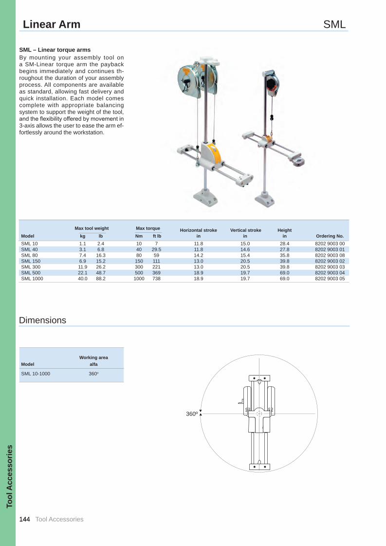
144
Tool
Acc
esso
ries
144 Tool Accessories
360º
Max tool weight Max torque Horizontal stroke vertical stroke Height Model kg lb Nm ft lb in in in Ordering No.SML 10 1.1 2.4 10 7 11.8 15.0 28.4 8202 9003 00SML 40 3.1 6.8 40 29.5 11.8 14.6 27.8 8202 9003 01SML 80 7.4 16.3 80 59 14.2 15.4 35.8 8202 9003 08SML 150 6.9 15.2 150 111 13.0 20.5 39.8 8202 9003 02SML 300 11.9 26.2 300 221 13.0 20.5 39.8 8202 9003 03SML 500 22.1 48.7 500 369 18.9 19.7 69.0 8202 9003 04SML 1000 40.0 88.2 1000 738 18.9 19.7 69.0 8202 9003 05
SML – Linear torque armsBy mounting your assembly tool on a SM-Linear torque arm the payback begins immediately and continues th-roughout the duration of your assembly process. All components are available as standard, allowing fast delivery and quick installation. Each model comes complete with appropriate balancing system to support the weight of the tool, andtheflexibilityofferedbymovementin3-axis allows the user to ease the arm ef-fortlessly around the workstation.
Linear Arm SML
Dimensions
working areaModel alfa
SML 10-1000 360o
Am_ToolAccessories.indd 144 2012-02-06 14:13:41
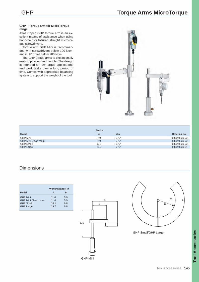
145
Tool
Acc
esso
ries
Tool Accessories 145
A
470
B
A
B
GHP – Torque arm for MicroTorque rangeAtlas Copco GHP torque arm is an ex-cellent means of assistance when using hand-heldorfixturedstraightmicrotor-que screwdrivers.
Torque arm GHP Mini is recommen-ded with screwdrivers below 100 Ncm, and GHP Small below 200 Ncm.
The GHP torque arms is exceptionally easy to position and handle. The design is intended for low torque applications and work tasks over a long period of time. Comes with appropriate balancing system to support the weight of the tool.
Stroke Model in alfa Ordering No.GHP Mini 7.9 270o 8432 0830 02GHP Mini Clean room 7.9 270o 8432 0830 92GHP Small 15.7 270o 8432 0830 03GHP Large 28.7 270o 8432 0830 04
GHP Mini
GHP Torque Arms MicroTorque
Dimensions
GHP Small/GHP Large
working range, inModel A B
GHP Mini 11.0 5.9GHP Mini Clean room 11.0 5.9GHP Small 18.1 9.8GHP Large 19.7 9.8
Am_ToolAccessories.indd 145 2012-02-06 14:13:43

146
Tool
Acc
esso
ries
146 Tool Accessories
Torque Arm Accessories
Optional Accessories for SMC carbon arms and SML, SMS T-series
Tool holders Description Ordering No.
SMC carbon arms SML and SMS T-series, torque range 12-25 Nm Spline 1 4390 1513 07Universal holder, dia 26-49 mm 4390 1510 86Tool holder, dia 30.5 mm for LUM12 HRX/HRF, 4390 1513 80 ETD STR21-16, LUM22 HR/HRX 3/4/6, ETP SL21-1/4/7/10, ETP ST32-5/10 Tool holder, dia 34 mm for LUF34 HR 4/8/16, ETP ST32 20 4390 1513 81Tool holder, dia 36.5 mm for LUM22 HR/HRX 10/12, TWIST22 HRX 7/10/12, 4390 1513 82 ETD SL/DL21 Tool holder, dia 38 mm for LUM25 HRF 05-U 4390 1513 83Tool holder, dia 46 mm, to be used with adapter 4390 1513 85Tool holder, dia 56 mm, to be used with adapter 4390 1513 86Special adapters to be used with dia 46 mm tool holder
LUM10 PR 4390 1734 09 LUM12 SR 4390 1735 52 LUM12 PR 4390 1735 53 LUM21 PR-P 4390 1735 44 LUM22 PR 4390 1735 54Special adapters to be used with dia 56 mm tool holder
LUM21 SR 4390 1735 45 LUM22 SR 4390 1735 51
SMC carbon arms SML and SMS T-series, torque range 50-100 NmSpline 1 4390 1513 08Spline 2 4390 1513 09Spline 3 4390 1513 10Tool holder, pistol ETP STR61-20/30, ETP DS7 4390 1518 18Tool holder, dia 24 mm, (Mounting 1) 4390 1518 22Spline 2, pistol 4390 1522 18
SMC carbon arms torque range 50-100 NmSpline 3, pistol 4390 1513 11Spline 2, pistol 4390 1526 18Tool holder ETV ST61-200, ETV ST81-200 4390 1513 87
SMC carbon arms, SMC 50Angle tool holder for LTV38-R50-13, LTV38-R42-13 4390 2062 80 LTV38-R50-HAD, LTV38-R42-HAD 4390 2062 81 LTV38-R50-10, LTV38-R42-10 4390 2062 82 LTV39-2 R30-10, LTV39-2 R37-10, 4390 2062 83 LTV39-2 R48-10 ETV ST61-40-10, ETV ST61-40-HAD, 4390 2062 84 ETV STB62-40-10, ETV STB62-50-10 ETV STB32-30-10, ETV ST61-30-10, 4390 2062 85 ETV STB62-30-10 LTV39-2 R48-13 4390 2062 86 LTV29-2 R30-10 4390 2062 87 ETV S72-30-10, ETV S42-30-10 4390 2062 88 ETV S72-40-10 4390 2062 89 ETV DS72-40-10 4390 2062 90
Universal tool holder
Tool holder
Spline
Angle tool holder
Am_ToolAccessories.indd 146 2012-02-06 14:13:49

147
Tool
Acc
esso
ries
Tool Accessories 147
Torque Arm Accessories
Optional Accessories for SMC carbon arms
Tool holders Description Ordering No.
SMC carbon arms, SMC100Angle tool holder for ETV ST81-100-13, ETV ST61-100-13, 4390 2061 80 ETV STB62-100-13 ETV DS72-70-HAD 4390 2061 81 ETV STB62-70-13, ETV ST81-70-13-L150, 4390 2061 82 ETV ST81-70-13, ETV ST61-70-13, ETV ST81-90-HAD, ETV ST61-90-HAD ETV S72-50-10/B10, LTV39-2 R70-13, 4390 2061 83 LTV39-2 R56-13, ETV S7-50-10 LTV39-2 R85-13 4390 2061 84 LTV38-R85-13 4390 2061 85 LTV38 R85-HAD 4390 2061 86 ETV ST81-50-10, ETV ST61-50-HAD, 4390 2061 87 ETV ST61-50-10, LTV39-2 R56-10 ETV ST101-100-HAD, ETV ST101-100-13, 4390 2061 88 ETV ST101-100-INTEL, ETV S72-100-13 LTV38 R70-13 4390 2061 89 LTV38 R57-13 4390 2061 90 ETV DS72-70-13 4390 2061 91 ETV DS92-100-13 4390 2061 92 ETV S72-70-13 4390 2061 93 ETV DS72-50-HAD, ETV DS72-50-10 4390 2061 94
SMC carbon arms, SMC200Spline 3, pistol 4390 1513 11Spline 2, pistol 4390 1526 18Angle tool holder for ETV ST61-200, ETV ST81-200 4390 1513 87 ETV ST101-180-13, ETV S92-180-13, 4390 2060 80 ETV S72-150-13, ETV S72-180-13 ETV ST61-150-13 ,ETV ST61-180-13, 4390 2060 81 ETV ST81-150-13, ETV ST81-180-13 ETV DS92-180-13 4390 2060 82 ETV DS72-160-13, ETV DS72-180-13 4390 2060 83 LTV48 R120-L13, LTV48 R150-L13, 4390 2060 84 LTV48 R200-L13 LTV69 R180-13, LTV69 N180-13 4390 2060 85 ETV DS72-180-13, LTV48 R150-HAD, 4390 2060 86 LTV48 R200-HAD, LTV48 R200-FS, LTV48 R120-FS, LTV48 R150-FS ETV ST61-150-FS, ETV ST61-180-FS, 4390 2060 87 ETV ST61-120-HAD, ETV ST61-150-HAD, ETV ST61-180-HAD, ETV ST81-120-HAD, ETV ST81-150-FS, ETV ST81-180-FS, ETV ST81-150-HAD, ETV ST81-180-HAD ETV ST101-180-FS, ETV ST101-180-Intel, 4390 2060 88 ETV ST101-180-HAD ETV DS72-160-FS, ETV DS72-160-HAD, 4390 2060 89 ETV DS72-100-HAD ETV DS72-100-13 4390 2060 90
Holder for bench stand Stand attachment 12-25 Nm 4390 1510 88 Stand attachment 50-100 Nm 4390 1518 88 SMC 200 should not be used with table standBench stand Bench stand with height 753 mm. 4390 1728 00 Holder must be ordered separately, Ordering No. 4390 1729 00. Table clamp Clamp for heavy duty applications, 22-82 mm 4390 1734 02 Balancer kit SMC Balancer adapter kit. 4390 2050 00 ThekitfitswithbalancersCOL1,RIL1C-5C, RIL 10C-22C and WP10. SMC Balancer adapter kit for WP05 4390 2078 80
Holder for bench stand
Table clamp
Bench stand
Angle tool holder
Am_ToolAccessories.indd 147 2012-02-06 14:13:54
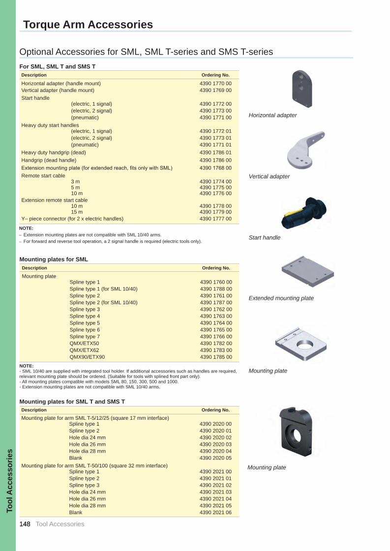
148
Tool
Acc
esso
ries
148 Tool Accessories
Torque Arm Accessories
Vertical adapter
Start handle
Extended mounting plate
Horizontal adapter
Mounting plate
Optional Accessories for SML, SML T-series and SMS T-series
Description Ordering No.
Horizontal adapter (handle mount) 4390 1770 00Vertical adapter (handle mount) 4390 1769 00Start handle (electric, 1 signal) 4390 1772 00 (electric, 2 signal) 4390 1773 00 (pneumatic) 4390 1771 00Heavy duty start handles (electric, 1 signal) 4390 1772 01 (electric, 2 signal) 4390 1773 01 (pneumatic) 4390 1771 01Heavy duty handgrip (dead) 4390 1786 01Handgrip (dead handle) 4390 1786 00Extensionmountingplate(forextendedreach,fitsonlywithSML) 4390176800Remote start cable 3 m 4390 1774 00 5 m 4390 1775 00 10 m 4390 1776 00Extension remote start cable 10 m 4390 1778 00 15 m 4390 1779 00Y– piece connector (for 2 x electric handles) 4390 1777 00
Mounting plates for SML
For SML, SML T and SMS T
Mounting plate
Description Ordering No.
Mounting plate for arm SML T-5/12/25 (square 17 mm interface) Spline type 1 4390 2020 00 Spline type 2 4390 2020 01 Hole dia 24 mm 4390 2020 02 Hole dia 26 mm 4390 2020 03 Hole dia 28 mm 4390 2020 04 Blank 4390 2020 05Mounting plate for arm SML T-50/100 (square 32 mm interface) Spline type 1 4390 2021 00 Spline type 2 4390 2021 01 Spline type 3 4390 2021 02 Hole dia 24 mm 4390 2021 03 Hole dia 26 mm 4390 2021 04 Hole dia 28 mm 4390 2021 05 Blank 4390 2021 06
Description Ordering No.
Mounting plate Spline type 1 4390 1760 00 Spline type 1 (for SML 10/40) 4390 1788 00 Spline type 2 4390 1761 00 Spline type 2 (for SML 10/40) 4390 1787 00 Spline type 3 4390 1762 00 Spline type 4 4390 1763 00 Spline type 5 4390 1764 00 Spline type 6 4390 1765 00 Spline type 7 4390 1766 00 QMX/ETX50 4390 1782 00 QMX/ETX62 4390 1783 00 QMX90/ETX90 4390 1785 00
NOTE:- SML 10/40 are supplied with integrated tool holder. If additional accessories such as handles are required, relevant mounting plate should be ordered. (Suitable for tools with splined front part only).- All mounting plates compatible with models SML 80, 150, 300, 500 and 1000.- Extension mounting plates are not compatible with SML 10/40 arms.
Mounting plates for SML T and SMS T
NOTE:– Extension mounting plates are not compatible with SML 10/40 arms.– For forward and reverse tool operation, a 2 signal handle is required (electric tools only).
Am_ToolAccessories.indd 148 2012-02-06 14:13:56
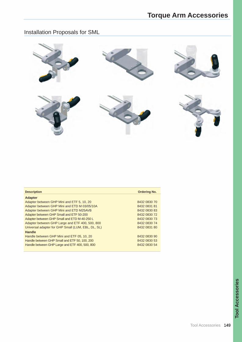
149
Tool
Acc
esso
ries
Tool Accessories 149
Installation Proposals for SML
Torque Arm Accessories
Description Ordering No.
AdapterAdapter between GHP Mini and ETF 5, 10, 20 8432 0830 70Adapter between GHP Mini and ETD M 03/05/10A 8432 0831 81Adapter between GHP Mini and ETD M25AVB 8432 0830 83Adapter between GHP Small and ETF 50-200 8432 0830 72Adapter between GHP Small and ETD M-40-250 L 8432 0830 73Adapter between GHP Large and ETF 400, 500, 800 8432 0830 74Universal adapter for GHP Small (LUM, EBL, DL, SL) 8432 0831 80Handle Handle between GHP Mini and ETF 05, 10, 20 8432 0830 90Handle between GHP Small and ETF 50, 100, 200 8432 0830 53Handle between GHP Large and ETF 400, 500, 800 8432 0830 54
Am_ToolAccessories.indd 149 2012-02-06 14:14:05
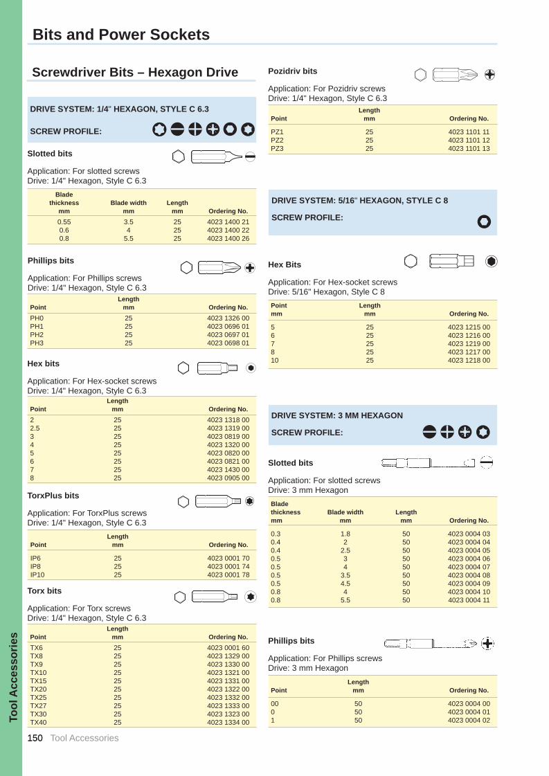
150
Tool
Acc
esso
ries
150 Tool Accessories
Screwdriver Bits – Hexagon Drive
DRIvE SySTEM: 1/4" HExAGON, STyLE C 6.3
SCREw PROFILE:
Slotted bits
Application: For slotted screwsDrive: 1/4" Hexagon, Style C 6.3
Phillips bits
Application: For Phillips screwsDrive: 1/4" Hexagon, Style C 6.3
Hex bits
Application: For Hex-socket screwsDrive: 1/4" Hexagon, Style C 6.3
Pozidriv bits
Application: For Pozidriv screwsDrive: 1/4" Hexagon, Style C 6.3
Hex Bits
Application: For Hex-socket screwsDrive: 5/16" Hexagon, Style C 8
DRIvE SySTEM: 5/16" HExAGON, STyLE C 8
SCREw PROFILE:
Blade thickness Blade width Length mm mm mm Ordering No. 0.55 3.5 25 4023 1400 21 0.6 4 25 4023 1400 22 0.8 5.5 25 4023 1400 26
Length Point mm Ordering No.PH0 25 4023 1326 00PH1 25 4023 0696 01PH2 25 4023 0697 01PH3 25 4023 0698 01
Length Point mm Ordering No.2 25 4023 1318 002.5 25 4023 1319 003 25 4023 0819 004 25 4023 1320 005 25 4023 0820 006 25 4023 0821 007 25 4023 1430 008 25 4023 0905 00
TorxPlus bits
Application: For TorxPlus screwsDrive: 1/4" Hexagon, Style C 6.3 Length Point mm Ordering No.
IP6 25 4023 0001 70IP8 25 4023 0001 74IP10 25 4023 0001 78
Length Point mm Ordering No.
PZ1 25 4023 1101 11PZ2 25 4023 1101 12PZ3 25 4023 1101 13
Point Length mm mm Ordering No.
5 25 4023 1215 006 25 4023 1216 007 25 4023 1219 008 25 4023 1217 0010 25 4023 1218 00
Length Point mm Ordering No.TX6 25 4023 0001 60TX8 25 4023 1329 00TX9 25 4023 1330 00TX10 25 4023 1321 00TX15 25 4023 1331 00TX20 25 4023 1322 00TX25 25 4023 1332 00TX27 25 4023 1333 00TX30 25 4023 1323 00TX40 25 4023 1334 00
Torx bits
Application: For Torx screwsDrive: 1/4" Hexagon, Style C 6.3
Bits and Power Sockets
Blade thickness Blade width Length mm mm mm Ordering No.
0.3 1.8 50 4023 0004 030.4 2 50 4023 0004 040.4 2.5 50 4023 0004 050.5 3 50 4023 0004 060.5 4 50 4023 0004 070.5 3.5 50 4023 0004 080.5 4.5 50 4023 0004 090.8 4 50 4023 0004 100.8 5.5 50 4023 0004 11
Length Point mm Ordering No.
00 50 4023 0004 000 50 4023 0004 011 50 4023 0004 02
Slotted bits
Application: For slotted screwsDrive: 3 mm Hexagon
Phillips bits
Application: For Phillips screwsDrive: 3 mm Hexagon
DRIvE SySTEM: 3 MM HExAGON
SCREw PROFILE:
Am_ToolAccessories.indd 150 2012-02-06 14:14:08
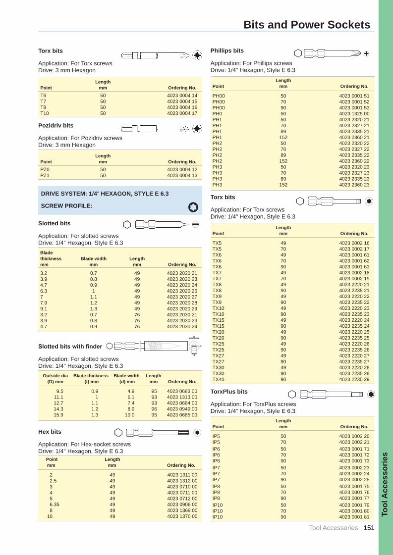
151
Tool
Acc
esso
ries
Tool Accessories 151
D
d
t
Phillips bits
Application: For Phillips screwsDrive: 1/4" Hexagon, Style E 6.3
Hex bits
Application: For Hex-socket screwsDrive: 1/4" Hexagon, Style E 6.3
Torx bits
Application: For Torx screwsDrive: 1/4" Hexagon, Style E 6.3
TorxPlus bits
Application: For TorxPlus screwsDrive: 1/4" Hexagon, Style E 6.3
Length Point mm Ordering No.
PH00 50 4023 0001 51PH00 70 4023 0001 52PH00 90 4023 0001 53PH0 50 4023 1325 00PH1 50 4023 2320 21PH1 70 4023 2327 21PH1 89 4023 2335 21PH1 152 4023 2360 21PH2 50 4023 2320 22PH2 70 4023 2327 22PH2 89 4023 2335 22PH2 152 4023 2360 22PH3 50 4023 2320 23PH3 70 4023 2327 23PH3 89 4023 2335 23PH3 152 4023 2360 23
Point Length mm mm Ordering No.
2 49 4023 1311 00 2.5 49 4023 1312 00 3 49 4023 0710 00 4 49 4023 0711 00 5 49 4023 0712 00 6.35 49 4023 0906 00 8 49 4023 1369 00 10 49 4023 1370 00
Length Point mm Ordering No.
TX5 49 4023 0002 16TX5 70 4023 0002 17TX6 49 4023 0001 61TX6 70 4023 0001 62TX6 90 4023 0001 63TX7 49 4023 0002 18TX7 70 4023 0002 19TX8 49 4023 2220 21TX8 90 4023 2235 21TX9 49 4023 2220 22TX9 90 4023 2235 22TX10 49 4023 2220 23TX10 90 4023 2235 23TX15 49 4023 2220 24TX15 90 4023 2235 24TX20 49 4023 2220 25TX20 90 4023 2235 25TX25 49 4023 2220 26TX25 90 4023 2235 26TX27 49 4023 2220 27TX27 90 4023 2235 27TX30 49 4023 2220 28TX30 90 4023 2235 28TX40 90 4023 2235 29
Length Point mm Ordering No.
IP5 50 4023 0002 20IP5 70 4023 0002 21IP6 50 4023 0001 71IP6 70 4023 0001 72IP6 90 4023 0001 73IP7 50 4023 0002 23IP7 70 4023 0002 24IP7 90 4023 0002 25IP8 50 4023 0001 75IP8 70 4023 0001 76IP8 90 4023 0001 77IP10 50 4023 0001 79IP10 70 4023 0001 80IP10 90 4023 0001 81
Bits and Power Sockets
Slotted bits with finder
Application: For slotted screwsDrive: 1/4" Hexagon, Style E 6.3 Outside dia Blade thickness Blade width Length (D) mm (t) mm (d) mm mm Ordering No.
9.5 0.9 4.9 95 4023 0683 00 11.1 1 6.1 93 4023 1313 00 12.7 1.1 7.4 93 4023 0684 00 14.3 1.2 8.9 96 4023 0949 00 15.9 1.3 10.0 95 4023 0685 00
Torx bits
Application: For Torx screwsDrive: 3 mm Hexagon
Length Point mm Ordering No.T6 50 4023 0004 14T7 50 4023 0004 15T8 50 4023 0004 16T10 50 4023 0004 17
Pozidriv bits
Application: For Pozidriv screwsDrive: 3 mm Hexagon
Length Point mm Ordering No.PZ0 50 4023 0004 12PZ1 50 4023 0004 13
Slotted bits
Application: For slotted screwsDrive: 1/4" Hexagon, Style E 6.3
DRIvE SySTEM: 1/4" HExAGON, STyLE E 6.3
SCREw PROFILE:
Blade thickness Blade width Length mm mm mm Ordering No.
3.2 0.7 49 4023 2020 213.9 0.8 49 4023 2020 234.7 0.9 49 4023 2020 246.3 1 49 4023 2020 267 1.1 49 4023 2020 277.9 1.2 49 4023 2020 289.1 1.3 49 4023 2020 293.2 0.7 76 4023 2030 213.9 0.8 76 4023 2030 234.7 0.9 76 4023 2030 24
Am_ToolAccessories.indd 151 2012-02-06 14:14:09
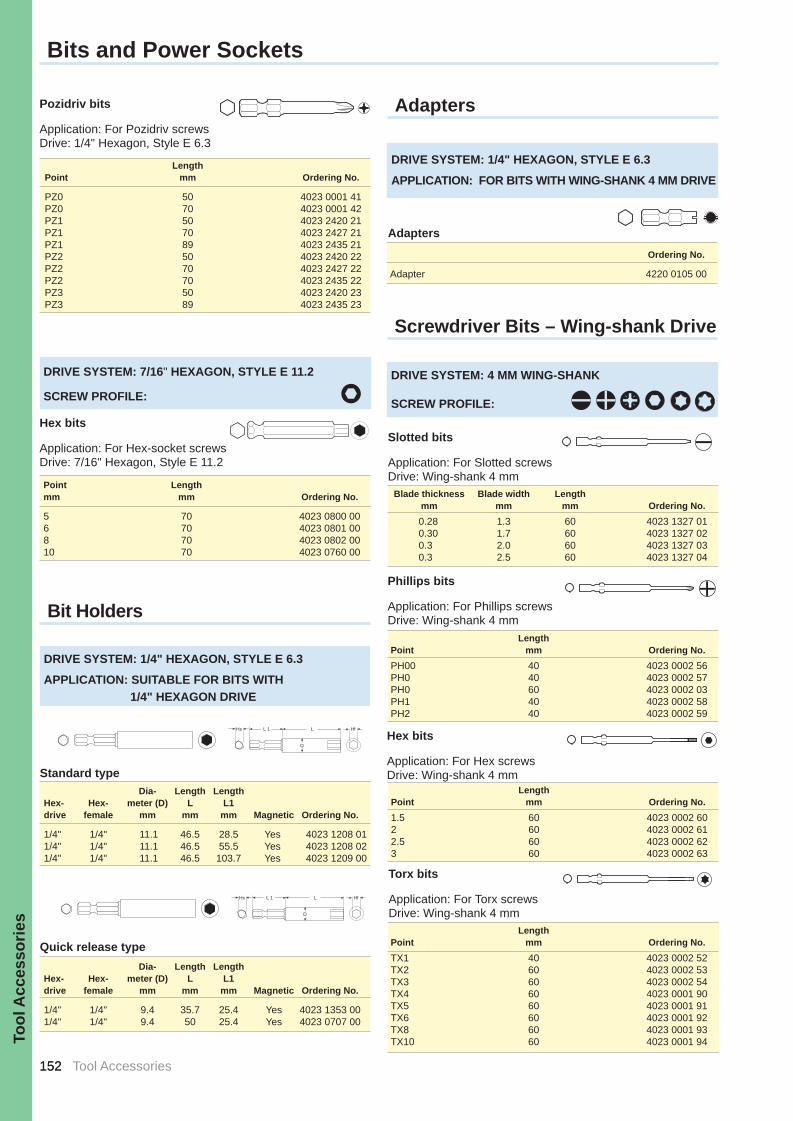
152
Tool
Acc
esso
ries
152 Tool Accessories
L 1 L HfHs
D
L 1 L HfHs
D
Dia- Length Length Hex- Hex- meter (D) L L1 drive female mm mm mm Magnetic Ordering No.
1/4" 1/4" 9.4 35.7 25.4 Yes 4023 1353 001/4" 1/4" 9.4 50 25.4 Yes 4023 0707 00
Bits and Power Sockets
Screwdriver Bits – wing-shank Drive
DRIvE SySTEM: 4 MM wING-SHANk
SCREw PROFILE:
Torx bits
Application: For Torx screwsDrive: Wing-shank 4 mm Length Point mm Ordering No.TX1 40 4023 0002 52TX2 60 4023 0002 53TX3 60 4023 0002 54TX4 60 4023 0001 90TX5 60 4023 0001 91TX6 60 4023 0001 92TX8 60 4023 0001 93TX10 60 4023 0001 94
Phillips bits
Application: For Phillips screwsDrive: Wing-shank 4 mm Length Point mm Ordering No.PH00 40 4023 0002 56PH0 40 4023 0002 57PH0 60 4023 0002 03PH1 40 4023 0002 58PH2 40 4023 0002 59
Hex bits
Application: For Hex screwsDrive: Wing-shank 4 mm Length Point mm Ordering No.1.5 60 4023 0002 602 60 4023 0002 612.5 60 4023 0002 623 60 4023 0002 63
Slotted bits
Application: For Slotted screwsDrive: Wing-shank 4 mm Blade thickness Blade width Length mm mm mm Ordering No. 0.28 1.3 60 4023 1327 01 0.30 1.7 60 4023 1327 02 0.3 2.0 60 4023 1327 03 0.3 2.5 60 4023 1327 04
Adapters Ordering No.
Adapter 4220 0105 00
Adapters
DRIvE SySTEM: 1/4" HExAGON, STyLE E 6.3
APPLICATION: FOR BITS wITH wING-SHANk 4 MM DRIvE
Quick release type
Pozidriv bits
Application: For Pozidriv screwsDrive: 1/4" Hexagon, Style E 6.3
Length Point mm Ordering No.
PZ0 50 4023 0001 41PZ0 70 4023 0001 42PZ1 50 4023 2420 21PZ1 70 4023 2427 21PZ1 89 4023 2435 21PZ2 50 4023 2420 22PZ2 70 4023 2427 22PZ2 70 4023 2435 22PZ3 50 4023 2420 23PZ3 89 4023 2435 23
DRIvE SySTEM: 7/16" HExAGON, STyLE E 11.2
SCREw PROFILE:
Hex bits
Application: For Hex-socket screwsDrive: 7/16" Hexagon, Style E 11.2
Point Length mm mm Ordering No.
5 70 4023 0800 006 70 4023 0801 008 70 4023 0802 0010 70 4023 0760 00
DRIvE SySTEM: 1/4" HExAGON, STyLE E 6.3
APPLICATION: SuITABLE FOR BITS wITH 1/4" HExAGON DRIvE
Bit Holders
Dia- Length Length Hex- Hex- meter (D) L L1 drive female mm mm mm Magnetic Ordering No.
1/4" 1/4" 11.1 46.5 28.5 Yes 4023 1208 011/4" 1/4" 11.1 46.5 55.5 Yes 4023 1208 021/4" 1/4" 11.1 46.5 103.7 Yes 4023 1209 00
Standard type
Am_ToolAccessories.indd 152 2012-02-06 14:14:11
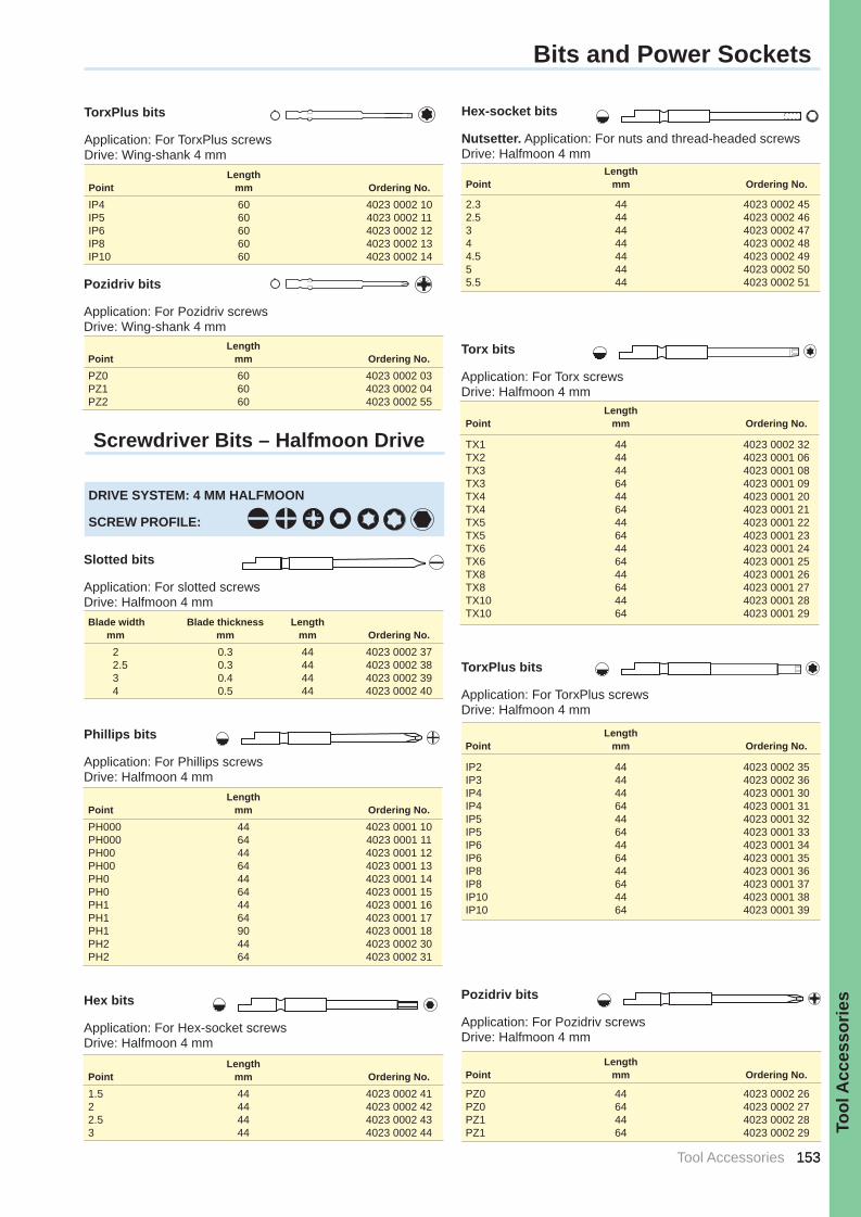
153
Tool
Acc
esso
ries
Tool Accessories 153
Screwdriver Bits – Halfmoon Drive
DRIvE SySTEM: 4 MM HALFMOON
SCREw PROFILE:
Torx bits
Application: For Torx screwsDrive: Halfmoon 4 mm Length Point mm Ordering No.
TX1 44 4023 0002 32TX2 44 4023 0001 06TX3 44 4023 0001 08TX3 64 4023 0001 09TX4 44 4023 0001 20TX4 64 4023 0001 21TX5 44 4023 0001 22TX5 64 4023 0001 23TX6 44 4023 0001 24TX6 64 4023 0001 25TX8 44 4023 0001 26TX8 64 4023 0001 27TX10 44 4023 0001 28TX10 64 4023 0001 29
Hex-socket bits
Nutsetter. Application: For nuts and thread-headed screwsDrive: Halfmoon 4 mm Length Point mm Ordering No.
2.3 44 4023 0002 452.5 44 4023 0002 463 44 4023 0002 474 44 4023 0002 484.5 44 4023 0002 495 44 4023 0002 505.5 44 4023 0002 51
Slotted bits
Application: For slotted screwsDrive: Halfmoon 4 mm Blade width Blade thickness Length mm mm mm Ordering No. 2 0.3 44 4023 0002 37 2.5 0.3 44 4023 0002 38 3 0.4 44 4023 0002 39 4 0.5 44 4023 0002 40
TorxPlus bits
Application: For TorxPlus screwsDrive: Wing-shank 4 mm Length Point mm Ordering No.IP4 60 4023 0002 10IP5 60 4023 0002 11IP6 60 4023 0002 12IP8 60 4023 0002 13IP10 60 4023 0002 14
Pozidriv bits
Application: For Pozidriv screwsDrive: Wing-shank 4 mm Length Point mm Ordering No.PZ0 60 4023 0002 03PZ1 60 4023 0002 04PZ2 60 4023 0002 55
Bits and Power Sockets
Phillips bits
Application: For Phillips screwsDrive: Halfmoon 4 mm Length Point mm Ordering No.PH000 44 4023 0001 10PH000 64 4023 0001 11PH00 44 4023 0001 12PH00 64 4023 0001 13PH0 44 4023 0001 14PH0 64 4023 0001 15PH1 44 4023 0001 16PH1 64 4023 0001 17PH1 90 4023 0001 18PH2 44 4023 0002 30PH2 64 4023 0002 31
Hex bits
Application: For Hex-socket screwsDrive: Halfmoon 4 mm Length Point mm Ordering No.1.5 44 4023 0002 412 44 4023 0002 422.5 44 4023 0002 433 44 4023 0002 44
TorxPlus bits
Application: For TorxPlus screwsDrive: Halfmoon 4 mm
Length Point mm Ordering No.
IP2 44 4023 0002 35IP3 44 4023 0002 36IP4 44 4023 0001 30IP4 64 4023 0001 31IP5 44 4023 0001 32IP5 64 4023 0001 33IP6 44 4023 0001 34IP6 64 4023 0001 35IP8 44 4023 0001 36IP8 64 4023 0001 37IP10 44 4023 0001 38IP10 64 4023 0001 39
Length Point mm Ordering No.
PZ0 44 4023 0002 26PZ0 64 4023 0002 27PZ1 44 4023 0002 28PZ1 64 4023 0002 29
Pozidriv bits
Application: For Pozidriv screwsDrive: Halfmoon 4 mm
Am_ToolAccessories.indd 153 2012-02-06 14:14:13
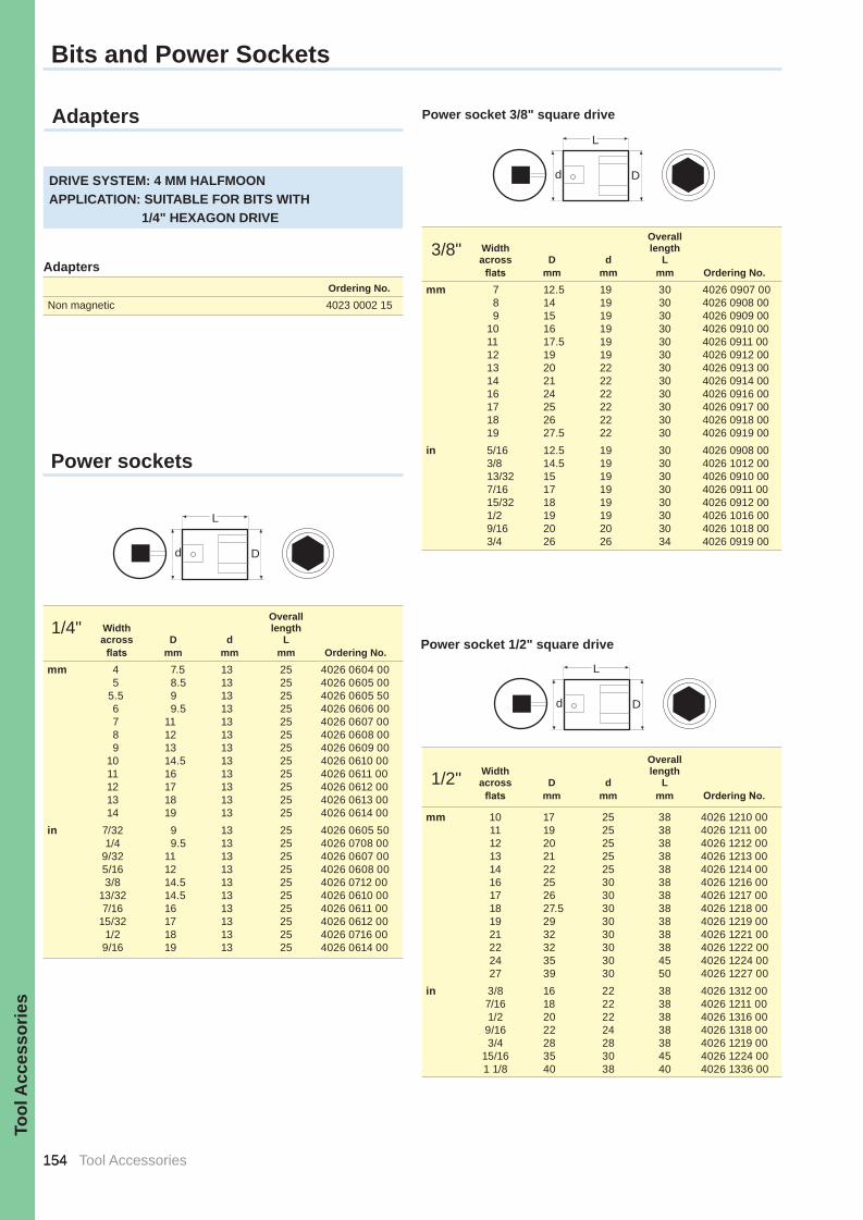
154
Tool
Acc
esso
ries
154 Tool Accessories
1/4"
3/8"
1/2"
D
L
d
D
L
d
Bits and Power Sockets
DRIvE SySTEM: 4 MM HALFMOONAPPLICATION: SuITABLE FOR BITS wITH 1/4" HExAGON DRIvE
Adapters
Adapters Ordering No.Non magnetic 4023 0002 15
D
L
d
Power sockets
Power socket 3/8" square drive
Power socket 1/2" square drive
Overall width length across D d L flats mm mm mm Ordering No.mm 4 7.5 13 25 4026 0604 00 5 8.5 13 25 4026 0605 00 5.5 9 13 25 4026 0605 50 6 9.5 13 25 4026 0606 00 7 11 13 25 4026 0607 00 8 12 13 25 4026 0608 00 9 13 13 25 4026 0609 00 10 14.5 13 25 4026 0610 00 11 16 13 25 4026 0611 00 12 17 13 25 4026 0612 00 13 18 13 25 4026 0613 00 14 19 13 25 4026 0614 00in 7/32 9 13 25 4026 0605 50 1/4 9.5 13 25 4026 0708 00 9/32 11 13 25 4026 0607 00 5/16 12 13 25 4026 0608 00 3/8 14.5 13 25 4026 0712 00 13/32 14.5 13 25 4026 0610 00 7/16 16 13 25 4026 0611 00 15/32 17 13 25 4026 0612 00 1/2 18 13 25 4026 0716 00 9/16 19 13 25 4026 0614 00
Overall width length across D d L flats mm mm mm Ordering No.mm 7 12.5 19 30 4026 0907 00 8 14 19 30 4026 0908 00 9 15 19 30 4026 0909 00 10 16 19 30 4026 0910 00 11 17.5 19 30 4026 0911 00 12 19 19 30 4026 0912 00 13 20 22 30 4026 0913 00 14 21 22 30 4026 0914 00 16 24 22 30 4026 0916 00 17 25 22 30 4026 0917 00 18 26 22 30 4026 0918 00 19 27.5 22 30 4026 0919 00in 5/16 12.5 19 30 4026 0908 00 3/8 14.5 19 30 4026 1012 00 13/32 15 19 30 4026 0910 00 7/16 17 19 30 4026 0911 00 15/32 18 19 30 4026 0912 00 1/2 19 19 30 4026 1016 00 9/16 20 20 30 4026 1018 00 3/4 26 26 34 4026 0919 00
Overall width length across D d L flats mm mm mm Ordering No.
mm 10 17 25 38 4026 1210 00 11 19 25 38 4026 1211 00 12 20 25 38 4026 1212 00 13 21 25 38 4026 1213 00 14 22 25 38 4026 1214 00 16 25 30 38 4026 1216 00 17 26 30 38 4026 1217 00 18 27.5 30 38 4026 1218 00 19 29 30 38 4026 1219 00 21 32 30 38 4026 1221 00 22 32 30 38 4026 1222 00 24 35 30 45 4026 1224 00 27 39 30 50 4026 1227 00in 3/8 16 22 38 4026 1312 00 7/16 18 22 38 4026 1211 00 1/2 20 22 38 4026 1316 00 9/16 22 24 38 4026 1318 00 3/4 28 28 38 4026 1219 00 15/16 35 30 45 4026 1224 00 1 1/8 40 38 40 4026 1336 00
Am_ToolAccessories.indd 154 2012-02-06 14:14:13
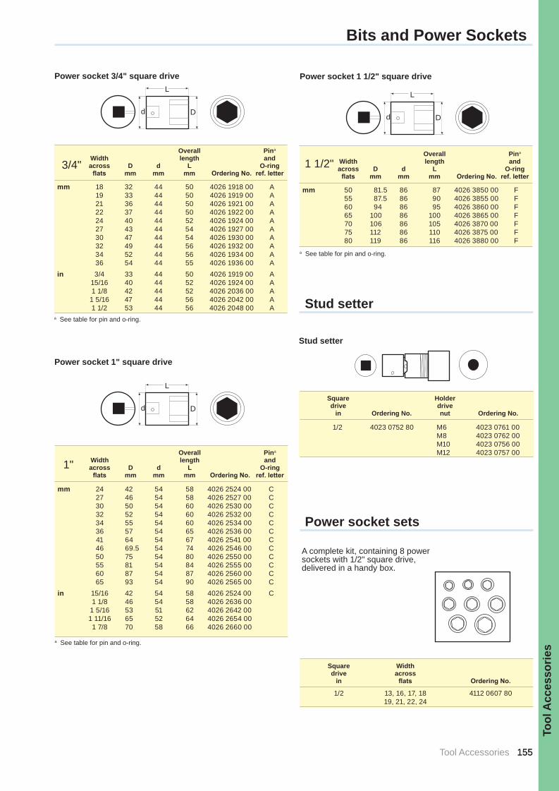
155
Tool
Acc
esso
ries
Tool Accessories 155
D
L
d
3/4"
D
L
d
D
L
d
1"
1 1/2"
A complete kit containing 8 powersockets with 1/2" square drive.
Bits and Power Sockets
Power socket 3/4" square drive
Overall Pina
width length and across D d L O-ring flats mm mm mm Ordering No. ref. letter
mm 18 32 44 50 4026 1918 00 A 19 33 44 50 4026 1919 00 A 21 36 44 50 4026 1921 00 A 22 37 44 50 4026 1922 00 A 24 40 44 52 4026 1924 00 A 27 43 44 54 4026 1927 00 A 30 47 44 54 4026 1930 00 A 32 49 44 56 4026 1932 00 A 34 52 44 56 4026 1934 00 A 36 54 44 55 4026 1936 00 Ain 3/4 33 44 50 4026 1919 00 A 15/16 40 44 52 4026 1924 00 A 1 1/8 42 44 52 4026 2036 00 A 1 5/16 47 44 56 4026 2042 00 A 1 1/2 53 44 56 4026 2048 00 A
a See table for pin and o-ring.
Power socket 1 1/2" square drive
Overall Pina
width length and across D d L O-ring flats mm mm mm Ordering No. ref. letter
mm 50 81.5 86 87 4026 3850 00 F 55 87.5 86 90 4026 3855 00 F 60 94 86 95 4026 3860 00 F 65 100 86 100 4026 3865 00 F 70 106 86 105 4026 3870 00 F 75 112 86 110 4026 3875 00 F 80 119 86 116 4026 3880 00 F
a See table for pin and o-ring.
Power socket 1" square drive
Square Holder drive drive in Ordering No. nut Ordering No.
1/2 4023 0752 80 M6 4023 0761 00 M8 4023 0762 00 M10 4023 0756 00 M12 4023 0757 00
Square width drive across in flats Ordering No.
1/2 13, 16, 17, 18 4112 0607 80 19, 21, 22, 24
A complete kit, containing 8 power sockets with 1/2" square drive, delivered in a handy box.
Stud setter
Power socket sets
Overall Pina
width length and across D d L O-ring flats mm mm mm Ordering No. ref. letter
mm 24 42 54 58 4026 2524 00 C 27 46 54 58 4026 2527 00 C 30 50 54 60 4026 2530 00 C 32 52 54 60 4026 2532 00 C 34 55 54 60 4026 2534 00 C 36 57 54 65 4026 2536 00 C 41 64 54 67 4026 2541 00 C 46 69.5 54 74 4026 2546 00 C 50 75 54 80 4026 2550 00 C 55 81 54 84 4026 2555 00 C 60 87 54 87 4026 2560 00 C 65 93 54 90 4026 2565 00 Cin 15/16 42 54 58 4026 2524 00 C 1 1/8 46 54 58 4026 2636 00 1 5/16 53 51 62 4026 2642 00 1 11/16 65 52 64 4026 2654 00 1 7/8 70 58 66 4026 2660 00
a See table for pin and o-ring.
Stud setter
Am_ToolAccessories.indd 155 2012-02-06 14:14:14
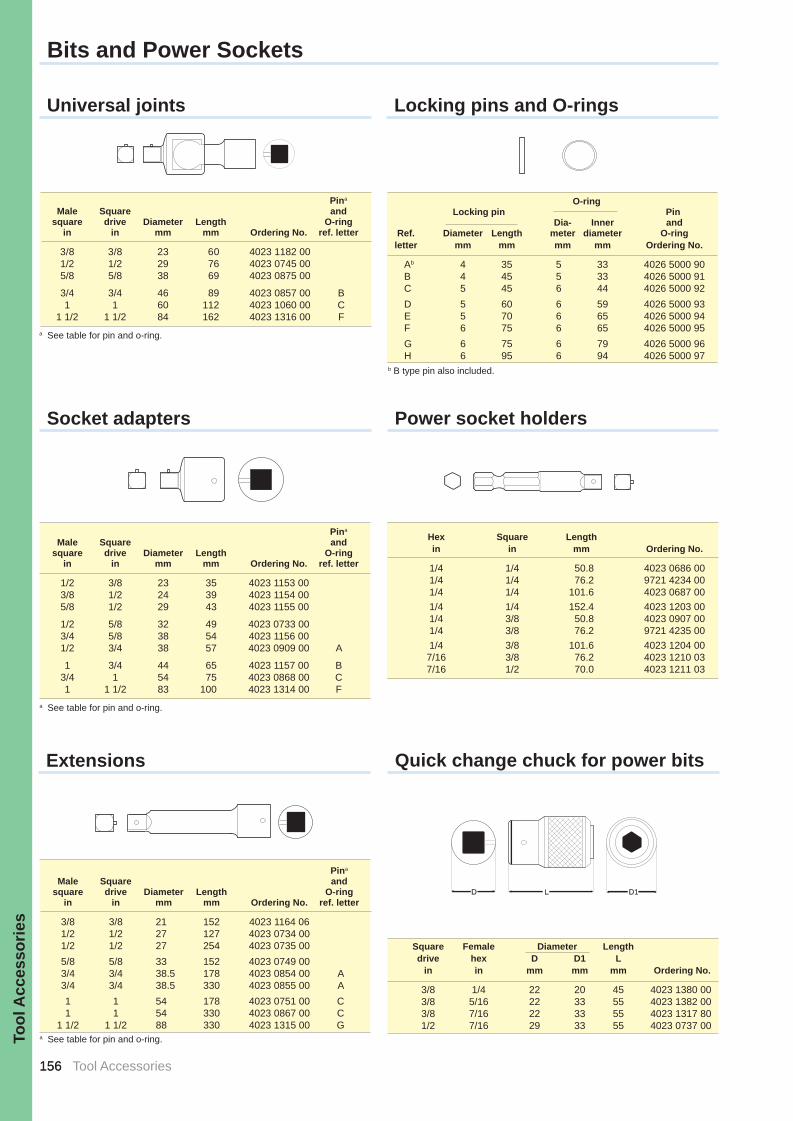
156
Tool
Acc
esso
ries
156 Tool Accessories
D L D1
Bits and Power Sockets
Pina
Male Square and square drive Diameter Length O-ring in in mm mm Ordering No. ref. letter
1/2 3/8 23 35 4023 1153 00 3/8 1/2 24 39 4023 1154 00 5/8 1/2 29 43 4023 1155 00
1/2 5/8 32 49 4023 0733 00 3/4 5/8 38 54 4023 1156 00 1/2 3/4 38 57 4023 0909 00 A
1 3/4 44 65 4023 1157 00 B 3/4 1 54 75 4023 0868 00 C 1 1 1/2 83 100 4023 1314 00 F
a See table for pin and o-ring.
Pina
Male Square and square drive Diameter Length O-ring in in mm mm Ordering No. ref. letter
3/8 3/8 23 60 4023 1182 00 1/2 1/2 29 76 4023 0745 00 5/8 5/8 38 69 4023 0875 00
3/4 3/4 46 89 4023 0857 00 B 1 1 60 112 4023 1060 00 C 1 1/2 1 1/2 84 162 4023 1316 00 F
a See table for pin and o-ring.
Pina
Male Square and square drive Diameter Length O-ring in in mm mm Ordering No. ref. letter
3/8 3/8 21 152 4023 1164 06 1/2 1/2 27 127 4023 0734 00 1/2 1/2 27 254 4023 0735 00 5/8 5/8 33 152 4023 0749 00 3/4 3/4 38.5 178 4023 0854 00 A 3/4 3/4 38.5 330 4023 0855 00 A 1 1 54 178 4023 0751 00 C 1 1 54 330 4023 0867 00 C 1 1/2 1 1/2 88 330 4023 1315 00 G
a See table for pin and o-ring.
O-ring Locking pin Pin Dia- Inner and Ref. Diameter Length meter diameter O-ring letter mm mm mm mm Ordering No.
Ab 4 35 5 33 4026 5000 90 B 4 45 5 33 4026 5000 91 C 5 45 6 44 4026 5000 92 D 5 60 6 59 4026 5000 93 E 5 70 6 65 4026 5000 94 F 6 75 6 65 4026 5000 95 G 6 75 6 79 4026 5000 96 H 6 95 6 94 4026 5000 97
Hex Square Length in in mm Ordering No.
1/4 1/4 50.8 4023 0686 00 1/4 1/4 76.2 9721 4234 00 1/4 1/4 101.6 4023 0687 00 1/4 1/4 152.4 4023 1203 00 1/4 3/8 50.8 4023 0907 00 1/4 3/8 76.2 9721 4235 00 1/4 3/8 101.6 4023 1204 00 7/16 3/8 76.2 4023 1210 03 7/16 1/2 70.0 4023 1211 03
Square Female Diameter Length drive hex D D1 L in in mm mm mm Ordering No.
3/8 1/4 22 20 45 4023 1380 00 3/8 5/16 22 33 55 4023 1382 00 3/8 7/16 22 33 55 4023 1317 80 1/2 7/16 29 33 55 4023 0737 00
universal joints
Socket adapters
Extensions
Locking pins and O-rings
Power socket holders
Quick change chuck for power bits
b B type pin also included.
Am_ToolAccessories.indd 156 2012-02-06 14:14:15

Fixtured Applications
Contents PageIntroduction ....................................... 158Fixtured nutrunners QST .................. 160Fixtured nutrunners ETX .................. 164Power MACS .................................... 167MSB, DB ........................................... 168Power Focus..................................... 171ToolsTalk ........................................... 172
Am_Fixturedapplications.indd 157 2012-02-07 10:11:23
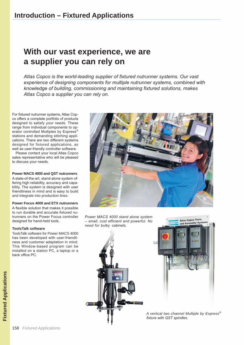
Fi
xtur
ed A
pplic
atio
ns
158 Fixtured Applications
Introduction – Fixtured Applications
For fixtured nutrunner systems, Atlas Cop-co offers a complete portfolio of products designed to satisfy your needs. These range from individual components to op-erator controlled Multiples by Express® stations and demanding stitching appli-cations. There are two different systems designed for fixtured applications, as well as user-friendly controller software.
Please contact your local Atlas Copco sales representative who will be pleased to discuss your needs.
Power MACS 4000 and QST nutrunnersA state-of-the-art, stand-alone system of-fering high reliability, accuracy and capa-bility. The system is designed with user friendliness in mind and is easy to build and integrate into production lines.
Power Focus 4000 and ETX nutrunnersA flexible solution that makes it possible to run durable and accurate fixtured nu-trunners on the Power Focus controller designed for hand-held tools.
ToolsTalk softwareToolsTalk software for Power MACS 4000 has been developed with user-friendli-ness and customer adaptation in mind. This Window-based program can be installed on a station PC, a laptop or a back office PC.
A vertical two channel Multiple by Express® fixture with QST spindles.
Power MACS 4000 stand alone system – small, cost efficient and powerful. No need for bulky cabinets.
With our vast experience, we area supplier you can rely onAtlas Copco is the world-leading supplier of fixtured nutrunner systems. Our vast experience of designing components for multiple nutrunner systems, combined with knowledge of building, commissioning and maintaining fixtured solutions, makes Atlas Copco a supplier you can rely on.
Am_Fixturedapplications.indd 158 2012-02-07 10:11:38

Fixt
ured
App
licat
ions
Fixtured Applications 159
QST and ETX nutrunners – common featuresDesigned specifically for fixtured sys-tems, these two reliable, durable nutrun-ners have many common features.
With QST and ETX nutrunners pilot mount or sandwich are possible. Differ-ent socket holder lengths (0-200 mm) permit access to applications or parts with tight clearances. For longer bolt lengths, spring travel can be increased from the standard 50 mm to 76 or 100 mm on request.
A built-in memory chip in QST and ETX nutrunners stores calibration values and general tool and service data. Both tools are ISO certified to +/- 2.5% accu-racy and 1 million duty cycles on hard and soft joints.
QST and ETX – different featuresThe QST nutrunner is available in inline, off-set, angle head, angle head travel, U-shaped, angle, SPN and co-axial de-signs. The ETX comes in inline, offset and angle head versions.
Connectors on both tools are de-signed to provide cable management flexibility. The robust connector and pin design on the QST is adjustable in 2 DOF. The ETX has a rotatable single connector.
QST offers a standard torque range of 2-1,750 Nm (up to 8,000 on request) and has a 60 m cable. ETX has a torque range of 6-950 Nm and a cable length of 25 m.
Introduction – Fixtured Nutrunners
QST nutrunners – extra features l Digital communication between nut-
runner and controller.l Hot Swap – replace cable or spindle
without turning off the power.l Increased speed characteristics, up to
3,000 rpm.l Optional redundant angle encoder and
transducer.l MTBF better than 5 million cycles un-
der normal conditions.
Nutrunners to match your needs
The QST nutrunner is a true state-of-the-art product. Partnered with the Power MACS 4000 tightening con- troller, QST offers one of the most advanced and reli- able tightening solutions on the market. ETX nutrunners are compact, durable and easy to integrate. Since ETX is controlled by the Power Focus, like the Tensor S and Tensor ST tools, it is possible to achieve 100% controller commonality in a line.
Am_Fixturedapplications.indd 159 2012-02-07 10:11:50
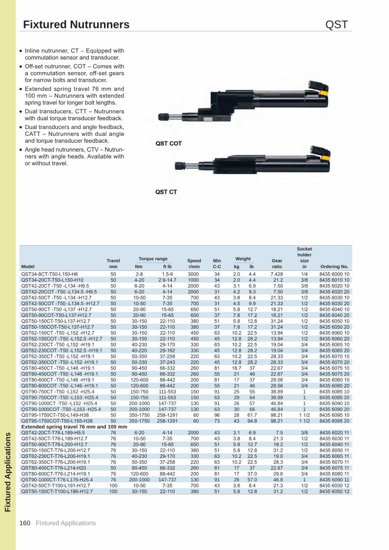
Fi
xtur
ed A
pplic
atio
ns
160 Fixtured Applications
Socket holder Travel Torque range Speed Min Weight Gear sizeModel mm Nm ft lb r/min C-C kg lb ratio in Ordering No.QST34-8CT-T50-L150-H6 50 2-8 1.5-6 3000 34 2.0 4.4 7.428 1/4 8435 6000 10QST34-20CT-T50-L150-H10 50 4-20 2.9-14.7 1000 34 2.0 4.4 21.2 3/8 8435 6010 10QST42-20CT -T50 -L134 -H9.5 50 6-20 4-14 2000 43 3.1 6.9 7.50 3/8 8435 6020 10QST42-20COT -T50 -L134.5 -H9.5 50 6-20 4-14 2000 31 4.2 9.3 7.50 3/8 8435 6020 20QST42-50CT -T50 -L134 -H12.7 50 10-50 7-35 700 43 3.8 8.4 21.33 1/2 8435 6030 10QST42-50COT -T50 -L134.5 -H12.7 50 10-50 7-35 700 31 4.5 9.9 21.33 1/2 8435 6030 20QST50-90CT -T50 -L137 -H12.7 50 20-90 15-65 650 51 5.8 12.7 18.21 1/2 8435 6040 10QST50-90COT-T50-L137-H12.7 50 20-90 15-65 650 37 7.8 17.2 18.21 1/2 8435 6040 20QST50-150CT-T50-L137-H12.7 50 30-150 22-110 380 51 5.8 12.8 31.24 1/2 8435 6050 10QST50-150COT-T50-L137-H12.7 50 30-150 22-110 380 37 7.8 17.2 31.24 1/2 8435 6050 20QST62-150CT -T50 -L152 -H12.7 50 30-150 22-110 450 63 10.2 22.5 13.94 1/2 8435 6060 10QST62-150COT -T50 -L152.5 -H12.7 50 30-150 22-110 450 45 12.8 28.2 13.94 1/2 8435 6060 20QST62-230CT -T50 -L152 -H19.1 50 40-230 29-170 330 63 10.2 22.5 19.04 3/4 8435 6065 10QST62-230COT -T50 -L152.5 -H19.1 50 40-220 29-162 330 45 12.8 28.2 19.04 3/4 8435 6065 20QST62-350CT -T50 -L152 -H19.1 50 50-350 37-258 220 63 10.2 22.5 28.33 3/4 8435 6070 10QST62-350COT -T50 -L152 -H19.1 50 50-330 37-243 220 45 12.8 28.2 28.33 3/4 8435 6070 20QST80-450CT -T50 -L146 -H19.1 50 90-450 66-332 260 81 16.7 37 22.67 3/4 8435 6075 10QST80-450COT -T50 -L146 -H19.1 50 90-450 66-332 260 55 21 46 22.67 3/4 8435 6075 20QST80-600CT -T50 -L146 -H19.1 50 120-600 88-442 200 81 17 37 29.56 3/4 8435 6080 10QST80-600COT -T50 -L146 -H19.1 50 120-600 88-442 200 55 21 46 29.56 3/4 8435 6080 20QST90-750CT -T50 -L152 -H25.4 50 150-750 111-553 150 91 25 55 38.89 1 8435 6085 10QST90-750COT -T50 -L153 -H25.4 50 150-750 111-553 150 63 29 64 38.89 1 8435 6085 20QST90-1000CT -T50 -L152 -H25.4 50 200-1000 147-737 130 91 26 57 46.84 1 8435 6090 10QST90-1000COT -T50 -L153 -H25.4 50 200-1000 147-737 130 63 30 66 46.84 1 8435 6090 20QST95-1750CT-T50-L149-H38 50 350-1750 258-1291 60 96 28 61.7 98.21 1 1/2 8435 6095 10QST95-1750COT-T50-L155-H38 50 350-1750 258-1291 60 73 43 94.8 98.21 1 1/2 8435 6095 20Extended spring travel 76 mm and 100 mm QST42-20CT-T76-L189-H9.5 76 6-20 4-14 2000 43 3.1 6.9 7.5 3/8 8435 6020 11QST42-50CT-T76-L189-H12.7 76 10-50 7-35 700 43 3.8 8.4 21.3 1/2 8435 6030 11QST50-90CT-T76-L200-H12.7 76 20-90 15-65 650 51 5.8 12.7 18.2 1/2 8435 6040 11QST50-150CT-T76-L200-H12.7 76 30-150 22-110 380 51 5.8 12.8 31.2 1/2 8435 6050 11QST62-230CT-T76-L200-H19.1 76 40-230 29-170 330 63 10.2 22.5 19.0 3/4 8435 6065 11QST62-350CT-T76-L200-H19.1 76 50-350 37-258 220 63 10.2 22.5 28.3 3/4 8435 6070 11QST80-450CT-T76-L214-H20 50 90-450 66-332 260 81 17 37 22.67 3/4 8435 6075 11QST80-600CT-T76-L214-H19.1 76 120-600 88-442 200 81 17 37.0 29.6 3/4 8435 6080 11QST90-1000CT-T76-L176-H25.4 76 200-1000 147-737 130 91 26 57.0 46.8 1 8435 6090 11QST42-50CT-T100-L191-H12.7 100 10-50 7-35 700 43 3.8 8.4 21.3 1/2 8435 6030 12QST50-150CT-T100-L186-H12.7 100 30-150 22-110 380 51 5.8 12.8 31.2 1/2 8435 6050 12
Fixtured Nutrunners QST
l Inline nutrunner, CT – Equipped with commutation sensor and transducer.
l Off-set nutrunner, COT – Comes with a commutation sensor, off-set gears for narrow bolts and transducer.
l Extended spring travel 76 mm and 100 mm – Nutrunners with extended spring travel for longer bolt lengths.
l Dual transducers, CTT – Nutrunners with dual torque transducer feedback.
l Dual transducers and angle feedback, CATT – Nutrunners with dual angle and torque transducer feedback.
l Angle head nutrunners, CTV – Nutrun-ners with angle heads. Available with or without travel.
Am_Fixturedapplications.indd 160 2012-02-07 10:11:51
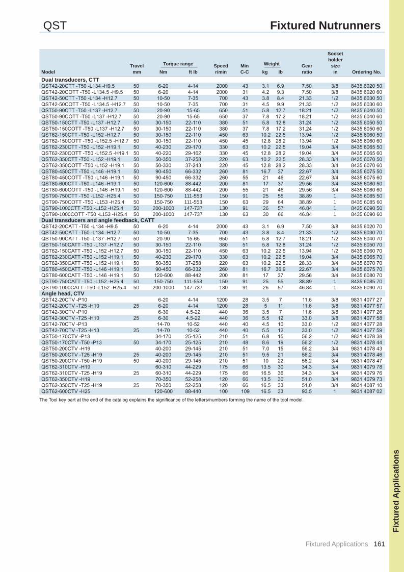
Fixt
ured
App
licat
ions
Fixtured Applications 161
QST Fixtured Nutrunners
Socket holder Travel Torque range Speed Min Weight Gear sizeModel mm Nm ft lb r/min C-C kg lb ratio in Ordering No.Dual transducers, CTT QST42-20CTT -T50 -L134 -H9.5 50 6-20 4-14 2000 43 3.1 6.9 7.50 3/8 8435 6020 50QST42-20COTT -T50 -L134.5 -H9.5 50 6-20 4-14 2000 31 4.2 9.3 7.50 3/8 8435 6020 60QST42-50CTT -T50 -L134 -H12.7 50 10-50 7-35 700 43 3.8 8.4 21.33 1/2 8435 6030 50QST42-50COTT -T50 -L134.5 -H12.7 50 10-50 7-35 700 31 4.5 9.9 21.33 1/2 8435 6030 60QST50-90CTT -T50 -L137 -H12.7 50 20-90 15-65 650 51 5.8 12.7 18.21 1/2 8435 6040 50QST50-90COTT -T50 -L137 -H12.7 50 20-90 15-65 650 37 7.8 17.2 18.21 1/2 8435 6040 60QST50-150CTT -T50 -L137 -H12.7 50 30-150 22-110 380 51 5.8 12.8 31.24 1/2 8435 6050 50QST50-150COTT -T50 -L137 -H12.7 50 30-150 22-110 380 37 7.8 17.2 31.24 1/2 8435 6050 60QST62-150CTT -T50 -L152 -H12.7 50 30-150 22-110 450 63 10.2 22.5 13.94 1/2 8435 6060 50QST62-150COTT -T50 -L152.5 -H12.7 50 30-150 22-110 450 45 12.8 28.2 13.94 1/2 8435 6060 60QST62-230CTT -T50 -L152 -H19.1 50 40-230 29-170 330 63 10.2 22.5 19.04 3/4 8435 6065 50QST62-230COTT -T50 -L152.5 -H19.1 50 40-220 29-162 330 45 12.8 28.2 19.04 3/4 8435 6065 60QST62-350CTT -T50 -L152 -H19.1 50 50-350 37-258 220 63 10.2 22.5 28.33 3/4 8435 6070 50QST62-350COTT -T50 -L152 -H19.1 50 50-330 37-243 220 45 12.8 28.2 28.33 3/4 8435 6070 60QST80-450CTT -T50 -L146 -H19.1 50 90-450 66-332 260 81 16.7 37 22.67 3/4 8435 6075 50QST80-450COTT -T50 -L146 -H19.1 50 90-450 66-332 260 55 21 46 22.67 3/4 8435 6075 60QST80-600CTT -T50 -L146 -H19.1 50 120-600 88-442 200 81 17 37 29.56 3/4 8435 6080 50QST80-600COTT -T50 -L146 -H19.1 50 120-600 88-442 200 55 21 46 29.56 3/4 8435 6080 60QST90-750CTT -T50 -L152 -H25.4 50 150-750 111-553 150 91 25 55 38.89 1 8435 6085 50QST90-750COTT -T50 -L153 -H25.4 50 150-750 111-553 150 63 29 64 38.89 1 8435 6085 60QST90-1000CTT -T50 -L152 -H25.4 50 200-1000 147-737 130 91 26 57 46.84 1 8435 6090 50QST90-1000COTT -T50 -L153 -H25.4 50 200-1000 147-737 130 63 30 66 46.84 1 8435 6090 60Dual transducers and angle feedback, CATT QST42-20CATT -T50 -L134 -H9.5 50 6-20 4-14 2000 43 3.1 6.9 7.50 3/8 8435 6020 70QST42-50CATT -T50 -L134 -H12.7 50 10-50 7-35 700 43 3.8 8.4 21.33 1/2 8435 6030 70QST50-90CATT -T50 -L137 -H12.7 50 20-90 15-65 650 51 5.8 12.7 18.21 1/2 8435 6040 70QST50-150CATT -T50 -L137 -H12.7 50 30-150 22-110 380 51 5.8 12.8 31.24 1/2 8435 6050 70QST62-150CATT -T50 -L152 -H12.7 50 30-150 22-110 450 63 10.2 22.5 13.94 1/2 8435 6060 70QST62-230CATT -T50 -L152 -H19.1 50 40-230 29-170 330 63 10.2 22.5 19.04 3/4 8435 6065 70QST62-350CATT -T50 -L152 -H19.1 50 50-350 37-258 220 63 10.2 22.5 28.33 3/4 8435 6070 70QST80-450CATT -T50 -L146 -H19.1 50 90-450 66-332 260 81 16.7 36.9 22.67 3/4 8435 6075 70QST80-600CATT -T50 -L146 -H19.1 50 120-600 88-442 200 81 17 37 29.56 3/4 8435 6080 70QST90-750CATT -T50 -L152 -H25.4 50 150-750 111-553 150 91 25 55 38.89 1 8435 6085 70QST90-1000CATT -T50 -L152 -H25.4 50 200-1000 147-737 130 91 26 57 46.84 1 8435 6090 70Angle head, CTV QST42-20CTV -P10 6-20 4-14 1200 28 3.5 7 11.6 3/8 9831 4077 27QST42-20CTV -T25 -H10 25 6-20 4-14 1200 28 5 11 11.6 3/8 9831 4077 57QST42-30CTV -P10 6-30 4.5-22 440 36 3.5 7 11.6 3/8 9831 4077 26QST42-30CTV -T25 -H10 25 6-30 4.5-22 440 36 5.5 12 33.0 3/8 9831 4077 58QST42-70CTV -P13 14-70 10-52 440 40 4.5 10 33.0 1/2 9831 4077 28QST42-70CTV -T25 -H13 25 14-70 10-52 440 40 5.5 12 33.0 1/2 9831 4077 59QST50-170CTV -P13 34-170 25-125 210 51 6.8 15 56.2 1/2 9831 4078 38QST50-170CTV -T50 -P13 50 34-170 25-125 210 48 8.6 19 56.2 1/2 9831 4078 44QST50-200CTV -H19 40-200 29-145 210 51 7.0 15 56.2 3/4 9831 4078 43QST50-200CTV -T25 -H19 25 40-200 29-145 210 51 9.5 21 56.2 3/4 9831 4078 46QST50-200CTV -T50 -H19 50 40-200 29-145 210 51 10 22 56.2 3/4 9831 4078 47QST62-310CTV -H19 60-310 44-229 175 66 13.5 30 34.3 3/4 9831 4079 78QST62-310CTV -T25 -H19 25 60-310 44-229 175 66 16.5 36 34.3 3/4 9831 4079 76QST62-350CTV -H19 70-350 52-258 120 66 13.5 30 51.0 3/4 9831 4079 73QST62-350CTV -T25 -H19 25 70-350 52-258 120 66 16.5 33 51.0 3/4 9831 4087 10QST62-600CTV -H25 120-600 88-440 100 109 16.5 33 93.5 1 9831 4087 02
The Tool key part at the end of the catalog explains the significance of the letters/numbers forming the name of the tool model.
Am_Fixturedapplications.indd 161 2012-02-07 10:11:51
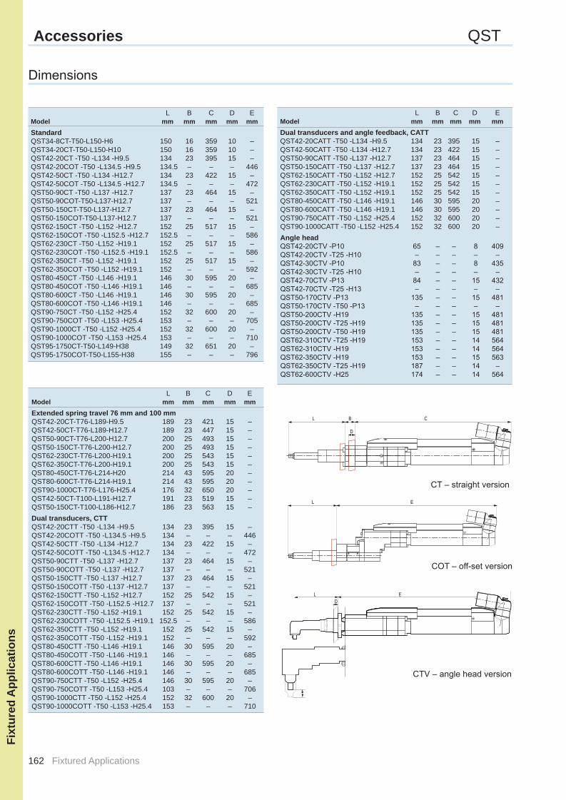
Fi
xtur
ed A
pplic
atio
ns
162 Fixtured Applications
L E
D
BL C
LD
E
Accessories QST
L B C D EModel mm mm mm mm mmDual transducers and angle feedback, CATT QST42-20CATT -T50 -L134 -H9.5 134 23 395 15 –QST42-50CATT -T50 -L134 -H12.7 134 23 422 15 –QST50-90CATT -T50 -L137 -H12.7 137 23 464 15 –QST50-150CATT -T50 -L137 -H12.7 137 23 464 15 –QST62-150CATT -T50 -L152 -H12.7 152 25 542 15 –QST62-230CATT -T50 -L152 -H19.1 152 25 542 15 –QST62-350CATT -T50 -L152 -H19.1 152 25 542 15 –QST80-450CATT -T50 -L146 -H19.1 146 30 595 20 –QST80-600CATT -T50 -L146 -H19.1 146 30 595 20 –QST90-750CATT -T50 -L152 -H25.4 152 32 600 20 –QST90-1000CATT -T50 -L152 -H25.4 152 32 600 20 –Angle head QST42-20CTV -P10 65 – – 8 409QST42-20CTV -T25 -H10 – – – – –QST42-30CTV -P10 83 – – 8 435QST42-30CTV -T25 -H10 – – – – –QST42-70CTV -P13 84 – – 15 432QST42-70CTV -T25 -H13 – – – – –QST50-170CTV -P13 135 – – 15 481QST50-170CTV -T50 -P13 – – – – –QST50-200CTV -H19 135 – – 15 481QST50-200CTV -T25 -H19 135 – – 15 481QST50-200CTV -T50 -H19 135 – – 15 481QST62-310CTV -T25 -H19 153 – – 14 564QST62-310CTV -H19 153 – – 14 564QST62-350CTV -H19 153 – – 15 563QST62-350CTV -T25 -H19 187 – – 14 –QST62-600CTV -H25 174 – – 14 564
Dimensions
L B C D EModel mm mm mm mm mmStandard QST34-8CT-T50-L150-H6 150 16 359 10 –QST34-20CT-T50-L150-H10 150 16 359 10 –QST42-20CT -T50 -L134 -H9.5 134 23 395 15 –QST42-20COT -T50 -L134.5 -H9.5 134.5 – – – 446QST42-50CT -T50 -L134 -H12.7 134 23 422 15 –QST42-50COT -T50 -L134.5 -H12.7 134.5 – – – 472QST50-90CT -T50 -L137 -H12.7 137 23 464 15 –QST50-90COT-T50-L137-H12.7 137 – – – 521QST50-150CT-T50-L137-H12.7 137 23 464 15 –QST50-150COT-T50-L137-H12.7 137 – – – 521QST62-150CT -T50 -L152 -H12.7 152 25 517 15 –QST62-150COT -T50 -L152.5 -H12.7 152.5 – – – 586QST62-230CT -T50 -L152 -H19.1 152 25 517 15 –QST62-230COT -T50 -L152.5 -H19.1 152.5 – – – 586QST62-350CT -T50 -L152 -H19.1 152 25 517 15 –QST62-350COT -T50 -L152 -H19.1 152 – – – 592QST80-450CT -T50 -L146 -H19.1 146 30 595 20 –QST80-450COT -T50 -L146 -H19.1 146 – – – 685QST80-600CT -T50 -L146 -H19.1 146 30 595 20 –QST80-600COT -T50 -L146 -H19.1 146 – – – 685QST90-750CT -T50 -L152 -H25.4 152 32 600 20 –QST90-750COT -T50 -L153 -H25.4 153 – – – 705QST90-1000CT -T50 -L152 -H25.4 152 32 600 20 –QST90-1000COT -T50 -L153 -H25.4 153 – – – 710QST95-1750CT-T50-L149-H38 149 32 651 20 –QST95-1750COT-T50-L155-H38 155 – – – 796
L B C D EModel mm mm mm mm mmExtended spring travel 76 mm and 100 mm QST42-20CT-T76-L189-H9.5 189 23 421 15 –QST42-50CT-T76-L189-H12.7 189 23 447 15 –QST50-90CT-T76-L200-H12.7 200 25 493 15 –QST50-150CT-T76-L200-H12.7 200 25 493 15 –QST62-230CT-T76-L200-H19.1 200 25 543 15 –QST62-350CT-T76-L200-H19.1 200 25 543 15 –QST80-450CT-T76-L214-H20 214 43 595 20 –QST80-600CT-T76-L214-H19.1 214 43 595 20 –QST90-1000CT-T76-L176-H25.4 176 32 650 20 –QST42-50CT-T100-L191-H12.7 191 23 519 15 –QST50-150CT-T100-L186-H12.7 186 23 563 15 –Dual transducers, CTT QST42-20CTT -T50 -L134 -H9.5 134 23 395 15 –QST42-20COTT -T50 -L134.5 -H9.5 134 – – – 446QST42-50CTT -T50 -L134 -H12.7 134 23 422 15 –QST42-50COTT -T50 -L134.5 -H12.7 134 – – – 472QST50-90CTT -T50 -L137 -H12.7 137 23 464 15 –QST50-90COTT -T50 -L137 -H12.7 137 – – – 521QST50-150CTT -T50 -L137 -H12.7 137 23 464 15 –QST50-150COTT -T50 -L137 -H12.7 137 – – – 521QST62-150CTT -T50 -L152 -H12.7 152 25 542 15 –QST62-150COTT -T50 -L152.5 -H12.7 137 – – – 521QST62-230CTT -T50 -L152 -H19.1 152 25 542 15 –QST62-230COTT -T50 -L152.5 -H19.1 152.5 – – – 586QST62-350CTT -T50 -L152 -H19.1 152 25 542 15 –QST62-350COTT -T50 -L152 -H19.1 152 – – – 592QST80-450CTT -T50 -L146 -H19.1 146 30 595 20 –QST80-450COTT -T50 -L146 -H19.1 146 – – – 685QST80-600CTT -T50 -L146 -H19.1 146 30 595 20 –QST80-600COTT -T50 -L146 -H19.1 146 – – – 685QST90-750CTT -T50 -L152 -H25.4 146 30 595 20 –QST90-750COTT -T50 -L153 -H25.4 103 – – – 706QST90-1000CTT -T50 -L152 -H25.4 152 32 600 20 –QST90-1000COTT -T50 -L153 -H25.4 153 – – – 710
COT – off-set version
CT – straight version
CTV – angle head version
Am_Fixturedapplications.indd 162 2012-02-07 10:11:52

Fixt
ured
App
licat
ions
Fixtured Applications 163
A
Length Ordering No. 2 m 4220 3799 02 3 m 4220 3799 03 5 m 4220 3799 05 7 m 4220 3799 07 10 m 4220 3799 10 15 m 4220 3799 15 20 m 4220 3799 20 25 m 4220 3799 25 30 m 4220 3799 30 35 m 4220 3799 35 40 m 4220 3799 40
Tool and extension cables
Tool and extension cable
Additional socket holder length
Socket holder Socket A size holdera
mm Product No. in Ordering No.
QST42-20CT 0b 8435 6020 10 3/8 4230 1818 00 50 8435 4083 08 3/8 4230 2217 00 100 8435 4083 10 3/8 4230 2217 01 150 8435 4083 12 3/8 4230 2217 02 200 8435 4083 14 3/8 4230 2217 03 QST42-50CT 0b 8435 6030 10 1/2 4230 1819 00 50 8435 4083 19 1/2 4230 2218 00 100 8435 4083 21 1/2 4230 2218 01 150 8435 4083 23 1/2 4230 2218 02 200 8435 4083 25 1/2 4230 2218 03 QST50-90CT 0b 8435 6040 10 1/2 4230 1820 00 50 8435 4083 28 1/2 4230 2219 00 100 8435 4083 29 1/2 4230 2219 01 150 8435 4083 30 1/2 4230 2219 02 200 8435 4083 31 1/2 4230 2219 03 QST50-150CT 0b 8435 6050 10 1/2 4230 1820 00 50 8435 4083 68 1/2 4230 2219 00 100 8435 4083 33 1/2 4230 2219 01 150 8435 4083 34 1/2 4230 2219 02 200 8435 4083 35 1/2 4230 2219 03 QST62-150CT 0b 8435 6060 10 1/2 4230 1829 00 50 8435 4083 37 1/2 4230 2223 00 100 8435 4083 40 1/2 4230 2223 01 150 8435 4083 43 1/2 4230 2223 02 200 8435 4083 46 1/2 4230 2223 03 0 8435 4083 70 5/8 4230 1821 00 50 8435 4083 38 5/8 4230 2224 00 100 8435 4083 41 5/8 4230 2224 01 150 8435 4083 44 5/8 4230 2224 02 200 8435 4083 47 5/8 4230 2224 03
Socket holder Socket A size holdera
mm Product No. in Ordering No.
QST62-230CT 0 8435 4083 81 5/8 4230 1821 00 50 8435 4083 83 5/8 4230 2224 00 100 8435 4083 98 5/8 4230 2224 01 150 8435 4083 88 5/8 4230 2224 02 200 8435 4083 91 5/8 4230 2224 03 0b 8435 5170 10 3/4 4230 1822 00 50 8435 4083 84 3/4 4230 2226 00 100 8435 4083 86 3/4 4230 2226 01 150 8435 4083 89 3/4 4230 2226 02 200 8435 4083 92 3/4 4230 2226 03 QST62-350CT 0 8435 4083 72 5/8 4230 1821 00 50 8435 4083 53 5/8 4230 2224 00 100 8435 4083 56 5/8 4230 2224 01 150 8435 4083 59 5/8 4230 2224 02 200 8435 4083 62 5/8 4230 2224 03 0b 8435 6070 10 3/4 4230 1822 00 50 8435 4083 54 3/4 4230 2226 00 100 8435 4083 57 3/4 4230 2226 01 150 8435 4083 60 3/4 4230 2226 02 200 8435 4083 63 3/4 4230 2226 03
a This socket holder is included when you order the complete spindle.b This socket holder follows when you order the standard nutrunner.NOTE: The spindle travel is 50 mm for all sockets holders.
Additional sockets
Optional Accessories
QST Accessories
Am_Fixturedapplications.indd 163 2012-02-07 10:12:01
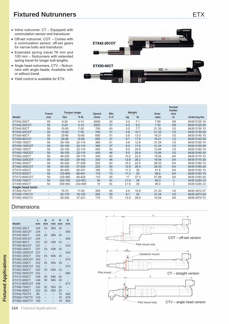
Fi
xtur
ed A
pplic
atio
ns
164 Fixtured Applications
L E
D
BL C
L
D
E
Pilot mount only
Pilot mount
Sandwich mount
COT – off-set version
CT – straight version
Fixtured Nutrunners ETX
CTV – angle head versionPilot mount only
L B C D EModel mm mm mm mm mmETX42-20CT 134 23 363 15 –ETX42-20COT 134 – – – 436ETX42-50CT 134 23 389 15 –ETX42-50COT 134 – – – 463ETX50-90CT 137 23 439 15 –ETX50-90COT 137 – – – 519ETX50-150CT 137 23 439 15 –ETX50-150COT 137 – – – 519ETX62-150CT 152 25 506 15 –ETX62-150COT 153 – – – 575ETX62-230CT 152 25 506 15 –ETX62-230COT 152 – – – 575ETX62-350CT 152 25 506 15 –ETX62-350COT 152 – – – 580ETX72-450CT 146 30 580 20 –ETX72-600CT 146 30 580 20 –ETX72-600COT 146 – – – 672ETX90-750CT 152 32 550 20 –ETX90-950CT 152 32 550 20 –ETX42-70CTV 85 – – 15 422ETX50-170CTV 133 – – 15 479ETX62-350CTV 153 – – 15 553
Dimensions
l Inline nutrunner, CT – Equipped with commutation sensor and transducer.
l Off-set nutrunner, COT – Comes with a commutation sensor, off-set gears for narrow bolts and transducer.
l Extended spring travel 76 mm and 100 mm – Nutrunners with extended spring travel for longer bolt lengths.
l Angle head nutrunners, CTV – Nutrun-ners with angle heads. Available with or without travel.
l Yield control is available for ETX.
Socket holder Travel Torque range Speed Min Weight Gear sizeModel mm Nm ft lb r/min C-C kg lb ratio in Ordering No.ETX42-20CT 50 6-20 4-14 2000 43 3.2 7.1 7.50 3/8 8435 5120 10ETX42-20COT 50 6-20 4-14 2000 31 4.3 9.5 7.50 3/8 8435 5120 20ETX42-50CT 50 10-50 7-35 700 43 3.5 7.7 21.33 1/2 8435 5130 10ETX42-50COT 50 10-50 7-35 700 31 4.6 10.1 21.33 1/2 8435 5130 20ETX50-90CT 50 20-90 15-65 650 51 5.9 13.0 18.21 1/2 8435 5140 10ETX50-90COT 50 20-90 15-65 650 37 8.1 17.9 18.21 1/2 8435 5140 20ETX50-150CT 50 30-150 22-110 380 51 5.8 12.8 31.24 1/2 8435 5150 10ETX50-150COT 50 30-150 22-110 380 37 8.0 17.6 31.24 1/2 8435 5150 20ETX62-150CT 50 30-150 22-110 450 63 9.5 20.9 13.94 1/2 8435 5160 10ETX62-150COT 50 30-150 22-110 450 46 9.5 20.9 13.94 1/2 8435 5160 20ETX62-230CT 50 40-230 29-170 330 63 10.2 22.5 19.04 3/4 8435 5170 10ETX62-230COT 50 40-220 29-162 330 46 12.8 28.2 19.04 3/4 8435 5170 20ETX62-350CT 50 50-350 37-258 220 63 10.2 22.5 28.33 3/4 8435 5180 10ETX62-350COT 50 50-330 37-243 220 50 12.9 28.4 28.33 3/4 8435 5180 20ETX72-450CT 50 90-450 65-331 160 73 11.3 25 41.6 3/4 8435 5182 10ETX72-600CT 50 120-600 90-441 110 73 11.3 25 58.0 3/4 8435 5183 10ETX72-600COT 50 120-580 90-425 110 55 17 37.5 57.99 3/4 8435 5183 20ETX90-750CT 50 150-750 110-551 90 91 17.8 39 68.3 1 8435 5184 10ETX90-950CT 50 200-950 150-699 70 91 17.8 39 90.0 1 8435 5185 10Angle head tools ETX42-70CTV - 15-70 11-50 355 45 4.9 10.8 21.33 1/2 8435 4072 07ETX50-170CTV - 22-170 16-125 200 50 9.1 20 31.24 1/2 8435 4073 04ETX62-350CTV - 50-350 37-221 175 70 13.9 28.9 19.04 3/4 8435 4074 72
Am_Fixturedapplications.indd 164 2012-02-07 10:12:03
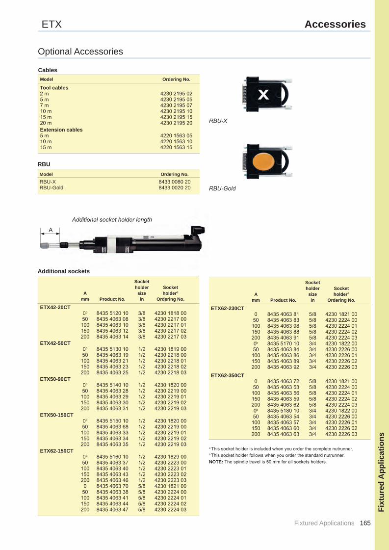
Fixt
ured
App
licat
ions
Fixtured Applications 165
Cables Model Ordering No.
Tool cables2 m 4230 2195 025 m 4230 2195 057 m 4230 2195 0710 m 4230 2195 1015 m 4230 2195 1520 m 4230 2195 20Extension cables5 m 4220 1563 0510 m 4220 1563 1015 m 4220 1563 15
ETX Accessories
A
Additional socket holder length
Optional Accessories
a This socket holder is included when you order the complete nutrunner.b This socket holder follows when you order the standard nutrunner.NOTE: The spindle travel is 50 mm for all sockets holders.
Socket holder Socket A size holdera
mm Product No. in Ordering No.
ETX42-20CT 0b 8435 5120 10 3/8 4230 1818 00 50 8435 4063 08 3/8 4230 2217 00 100 8435 4063 10 3/8 4230 2217 01 150 8435 4063 12 3/8 4230 2217 02 200 8435 4063 14 3/8 4230 2217 03ETX42-50CT 0b 8435 5130 10 1/2 4230 1819 00 50 8435 4063 19 1/2 4230 2218 00 100 8435 4063 21 1/2 4230 2218 01 150 8435 4063 23 1/2 4230 2218 02 200 8435 4063 25 1/2 4230 2218 03ETX50-90CT 0b 8435 5140 10 1/2 4230 1820 00 50 8435 4063 28 1/2 4230 2219 00 100 8435 4063 29 1/2 4230 2219 01 150 8435 4063 30 1/2 4230 2219 02 200 8435 4063 31 1/2 4230 2219 03ETX50-150CT 0b 8435 5150 10 1/2 4230 1820 00 50 8435 4063 68 1/2 4230 2219 00 100 8435 4063 33 1/2 4230 2219 01 150 8435 4063 34 1/2 4230 2219 02 200 8435 4063 35 1/2 4230 2219 03ETX62-150CT 0b 8435 5160 10 1/2 4230 1829 00 50 8435 4063 37 1/2 4230 2223 00 100 8435 4063 40 1/2 4230 2223 01 150 8435 4063 43 1/2 4230 2223 02 200 8435 4063 46 1/2 4230 2223 03 0 8435 4063 70 5/8 4230 1821 00 50 8435 4063 38 5/8 4230 2224 00 100 8435 4063 41 5/8 4230 2224 01 150 8435 4063 44 5/8 4230 2224 02 200 8435 4063 47 5/8 4230 2224 03
Socket holder Socket A size holdera
mm Product No. in Ordering No.
ETX62-230CT 0 8435 4063 81 5/8 4230 1821 00 50 8435 4063 83 5/8 4230 2224 00 100 8435 4063 98 5/8 4230 2224 01 150 8435 4063 88 5/8 4230 2224 02 200 8435 4063 91 5/8 4230 2224 03 0b 8435 5170 10 3/4 4230 1822 00 50 8435 4063 84 3/4 4230 2226 00 100 8435 4063 86 3/4 4230 2226 01 150 8435 4063 89 3/4 4230 2226 02 200 8435 4063 92 3/4 4230 2226 03ETX62-350CT 0 8435 4063 72 5/8 4230 1821 00 50 8435 4063 53 5/8 4230 2224 00 100 8435 4063 56 5/8 4230 2224 01 150 8435 4063 59 5/8 4230 2224 02 200 8435 4063 62 5/8 4230 2224 03 0b 8435 5180 10 3/4 4230 1822 00 50 8435 4063 54 3/4 4230 2226 00 100 8435 4063 57 3/4 4230 2226 01 150 8435 4063 60 3/4 4230 2226 02 200 8435 4063 63 3/4 4230 2226 03
Additional sockets
RBUModel Ordering No.RBU-X 8433 0080 20RBU-Gold 8433 0020 20 RBU-Gold
RBU-X
Am_Fixturedapplications.indd 165 2012-02-07 10:12:08

Fi
xtur
ed A
pplic
atio
ns
166 Fixtured Applications
Introduction – Controllers and Software
Power MACS 4000Power MACS 4000 is Atlas Copco’s lat-est, most advanced tightening controller for fixtured tools. It has effective tools for statistical process control to ensure that quality issues are identified long before they cause production problems.
The controller supports a zero-fault production philosophy with its capacity to collect tightening data for analysis, continuous improvement and traceabil-ity. Power MACS processing power and memory are designed to handle and send large amounts of data without influ-encing the tightening process.
Power FocusPower Focus is a modular range of con-trollers, with full flexibility, designed for applications ranging from single nut-runner hand-held operations to fixtured multiple nutrunnning systems. Advanced process control and monitoring functions make it easy to view and collect data us-ing the Internet infrastructure.
The Power Focus 4000 is available in two versions, Compact and Graph. The difference between them is the user inter-face, where the Graph features the color display and a full keyboard.
ToolsTalk Power MACSThe new ToolsTalk software for Power MACS 4000 has been developed with user friendliness and customer adapta-tion in mind and can be installed on a laptop or a back office PC.
Advanced process control and monitoring
State-of-the-art tightening controllers Power MACS 4000 and Power Focus with their advanced process control and monitoring functions, and supported by ToolsTalk soft-ware, can put your assembly operation on the path to zero-fault production.
Am_Fixturedapplications.indd 166 2012-02-07 10:12:09
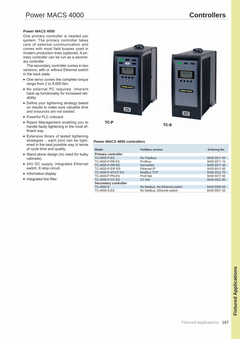
Fixt
ured
App
licat
ions
Fixtured Applications 167
Power MACS 4000One primary controller is needed per system. The primary controller takes care of external communication and comes with most field busses used in modern production lines (optional). A pri-mary controller can be run as a second-ary controller
The secondary controller comes in two versions; with or without Ethernet switch in the back plate.l One servo covers the complete torque
range from 2 to 8,000 Nm.l No external PC required, inherent
back-up functionality for increased reli-ability.
l Defi ne your tightening strategy based on results to make sure valuable time and resources are not wasted.
l Powerful PLC onboard.l Reject Management enabling you to
handle faulty tightening in the most ef-fi cient way.
l Extensive library of tested tightening strategies – each joint can be tight-ened in the best possible way in terms of cycle time and quality.
l Stand alone design (no need for bulky cabinets).
l 24V DC supply, integrated Ethernet switch, E-stop circuit.
l Informative displayl Integrated line fi lter.
Power MACS 4000 Controllers
Power MACS 4000 controllers
Model Fieldbus version Ordering No.Primary controllerTC-4000-P-ES No Fieldbus 8435 6511 00TC-4000-P-PB-ES Profi bus 8435 6511 10TC-4000-P-DN-ES DeviceNet 8435 6511 30TC-4000-P-EIP-ES Ethernet IP 8435 6511 60TC-4000-P-MTCP-ES ModBus TCP 8435 6511 70TC-4000-P-PN-ES Profi Net 8435 6511 50TC-4000-P-CC-ES CC link 8435 6511 80Secondary controllerTC-4000-S No fi eldbus, No Ethernet switch 8435 6500 00TC-4000-S-ES No fi eldbus, Ethernet switch 8435 6501 00
Am_Fixturedapplications.indd 167 2012-02-07 10:12:10

Fi
xtur
ed A
pplic
atio
ns
168 Fixtured Applications
Power Supply MSB, DB
Main Switch Box – MSBThe MSB is used for power distribution and makes power management easy. It is designed be fed with 380-480 VAC 3-phase without requiring an external transformer. The MSB leaves room for customer adaptations and the E-stop functionality can be upgraded from class 3 to class 4. Each MSB supplies up to 6 controllers with power.
Distribution Box – DBThe DB provides the same functionality as the MSB except for the main switch and is used as a complement to the MSB for systems with more than 6 channels. The DB II complies with all North American electrical codes.
General Box – GBAn empty DB, suitable for external system devices.
Service Box – SBThe SB converts 480 VAC to 120 VAC and includes (2) GFCI 120 VAC duplex receptacles for powering external devices (e.g., ComNode, PCs, Barcode scanner, etc.). The SB is not to be used to power Power Focus controllers.
Model Ordering No.MSBMain switch box (Max 6 channels) 8435 5660 00DBDB - Distribution box (Max 6 channels) + Power cable 1800 mm 8435 6560 50DB II - Distribution box (Max 6 channels) + Power cable 1800 mm, 8435 6560 10(North American version)GBGeneral box 4222 1249 85SBService box 9040 1102 10
Am_Fixturedapplications.indd 168 2012-02-07 10:12:11
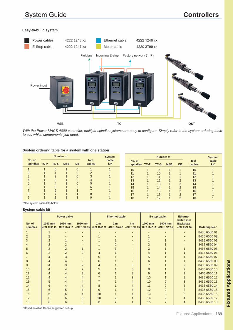
Fixt
ured
App
licat
ions
Fixtured Applications 169
Number of SystemNo. of tool cablespindles TC-P TC-S MSB DB cables kita
1 1 0 1 0 1 12 1 1 1 0 2 13 1 2 1 0 3 14 1 3 1 0 4 15 1 4 1 0 5 16 1 5 1 0 6 17 1 6 1 1 7 18 1 7 1 1 8 19 1 8 1 1 9 1
System Guide Controllers
System ordering table for a system with one station
Power cable Ethernet cable E-stop cable Ethernet switch incl.
No. of 1350 mm 1650 mm 1950 mm 1 m 2 m 3 m 1200 mm 3000 mm Backplate spindles 4222 1248 13 4222 1248 16 4222 1248 19 4222 1246 01 4222 1246 02 4222 1246 03 4222 1247 12 4222 1247 30 4222 0982 90 Ordering No.b
1 1 - - - - - - - - 8435 6560 012 2 - - 1 - - 1 - - 8435 6560 023 2 1 - 1 1 - 1 1 - 8435 6560 034 2 2 - 1 2 - 2 1 - 8435 6560 045 2 2 1 1 3 - 3 1 1 8435 6560 056 2 2 2 4 1 - 4 1 1 8435 6560 067 4 3 - 5 1 - 5 1 1 8435 6560 078 4 4 - 6 1 - 6 1 1 8435 6560 089 4 3 2 4 1 3 7 1 2 8435 6560 0910 4 4 2 5 1 3 8 1 2 8435 6560 1011 4 4 3 6 1 3 9 1 2 8435 6560 1112 4 4 4 7 1 3 10 1 2 8435 6560 1213 5 4 4 7 1 4 10 2 3 8435 6560 1314 6 4 4 8 1 4 11 2 3 8435 6560 1415 6 5 4 9 1 4 12 2 3 8435 6560 1516 6 6 4 10 1 4 13 2 3 8435 6560 1617 6 6 5 10 2 4 14 2 4 8435 6560 1718 6 6 6 11 2 4 15 2 4 8435 6560 18
Number of SystemNo. of tool cablespindles TC-P TC-S MSB DB cables kita
10 1 9 1 1 10 111 1 10 1 1 11 112 1 11 1 1 12 113 1 12 1 2 13 114 1 13 1 2 14 115 1 14 1 2 15 116 1 15 1 2 16 117 1 16 1 2 17 118 1 17 1 2 18 1
Power cables 4222 1248 xx
E-Stop cable 4222 1247 xx
With the Power MACS 4000 controller, multiple-spindle systems are easy to configure. Simply refer to the system ordering table to see which components you need.
a See system cable kits below.
b Based on Atlas Copco suggested set-up.
Ethernet cable 4222 1246 xx
Motor cable 4220 3799 xx
MSB TC QST
System cable kit
Easy-to-build system
Power input
Fieldbus Incoming E-stop Factory network (1 IP)
Am_Fixturedapplications.indd 169 2012-02-07 10:12:17

Fi
xtur
ed A
pplic
atio
ns
170 Fixtured Applications
Suitable for Length Ordering No.TC1-TC2, TC7-TC8, TC13-TC14 1350 mm 4222 1248 13TC3-TC4, TC9-TC10, TC15-TC16 1650 mm 4222 1248 16TC5-TC6, TC11-TC12, TC17-TC18 1950 mm 4222 1248 19For longer distances 5 m 4222 1248 50 10 m 4222 1370 10 15 m 4222 1370 15 20 m 4222 1370 20
Power cables between MSB and TC
Length Ordering No. 0.5 m 4222 1246 001 m 4222 1246 012 m 4222 1246 023 m 4222 1246 035 m 4222 1246 0510 m 4222 1246 1015 m 4222 1246 15
Ethernet cables
Components Length Ordering No.E-stop cable 1200 mm 4222 1247 12E-stop cable 3000 mm 4222 1247 30E-stop termination 4222 0755 00
E-stop cables and termination
Ethernet cable
E-stop cable
Power cable betwen MSB and TC
Indicator box
Model Ordering No.Operator handle (ball joint/handle)
- front/plastic 8435 3030 00 - front/rubber 8435 3030 01 - rear/plastic 8435 3030 02 - rear/rubber 8435 3030 03
Operator handle
Model Ordering No.Indicator box 8435 3010 03Indicator box cable to PM4K, 1 m 4243 0278 80Open end cable 5 m 4243 0281 05Extension cable 3 m 4243 0282 03 5 m 4243 0282 05 10 m 4243 0282 10 15 m 4243 0282 15 20 m 4243 0282 20 25 m 4243 0282 25
Indicator box and cable
Optional Accessories
Accessories Power MACS 4000
Operator handle
Am_Fixturedapplications.indd 170 2012-02-07 10:12:37

Fixt
ured
App
licat
ions
Fixtured Applications 171
Advanced process control and monitoring functionsPower Focus is a modular range of con-trollers, with full flexibility, designed for applications ranging from single spindle hand-held operations to fi xtured multiple nutrunnning systems. Advanced process control and monitoring functions make it easy to view and collect data using the Ethernet network.l Choose your controller – either Graph
or Compact.l Choose your RBU software key to run
a tool.l Choose from various ways to use the
controller, as a stand-alone or in a net-work.
l Run many different kinds of tool, stan-dard, FS, crowfoot or open tools.
l Realtime statistics analysis.l Error-proofi ng solution.l Advanced tightening control and/or
monitoring method.l Trace view.l Logic confi gurator.l Can handle different levels of commu-
nication.
Power Focus 4000 and ETX
Model Ordering No.Power Focus 4000 W 07PF 4000-G 8433 6100 00PF 4000-C 8433 6100 05PF 4000-G-DN 8433 6140 00PF 4000-C-DN 8433 6140 05PF 4000-C-FLN 8433 6141 05PF 4000-G-PB 8433 6142 00PF 4000-C-PB 8433 6142 05PF 4000-G-IB 8433 6145 00PF 4000-C-IB 8433 6145 05PF 4000-G-MB 8433 6147 00PF 4000-C-MB 8433 6147 05PF 4000-G-EIP 8433 6149 00PF 4000-C-EIP 8433 6149 05
Controller functionality
Hardware key Ordering No.RBU-Gold 8433 0020 20RBU-X 8433 0080 20
The Power Focus 4000 is available in two versions, Compact and Graph. The difference between them is the user in-terface, where the Graph features the color display and a full keyboard.
Compact This version offers full functionality at a lower cost, but requires a PC with the ToolsTalk PF software for process set-up.
GraphWith the Graph hardware, you have full stand-alone programming possibilities. When networked, the Graph can func-tion as a programming terminal for other Power Focus units.
RBU cuts downtimeAtlas Copco’s patented Rapid Backup Unit (RBU) concept transfers function-ality to a non-confi gured hardware unit, ensuring that hardware can easily be up-graded should functionality requirements change. The RBU also acts as back-up for programming and confi guration. If a change of hardware is required, just fi t the RBU to the new hardware, switch on the unit and you’re ready. All program-ming and network configurations are transferred in seconds. The RBU cuts downtime to a minimum.
Model Ordering No.Power Focus 4000 W 10PF 4000-G-HW 8433 7100 00PF 4000-C-HW 8433 7100 05PF 4000-G-DN- HW 8433 7140 00PF 4000-C-DN-HW 8433 7140 05PF 4000-G-FLN-HW 8433 7141 00PF 4000-C-FLN-HW 8433 7141 05PF 4000-G-PB-HW 8433 7142 00PF 4000-C-PB-HW 8433 7142 05PF 4000-G-CC-HW 8433 7143 00PF 4000-C-CC-HW 8433 7143 05PF 4000-G-IB-HW 8433 7145 00PF 4000-C-IB-HW 8433 7145 05PF 4000-G-MB-HW 8433 7147 00PF 4000-C-MB-HW 8433 7147 05PF 4000-G-PN-HW 8433 7148 00PF 4000-C-PN-HW 8433 7148 05PF 4000-G-EIP-HW 8433 7149 00PF 4000-C-EIP-HW 8433 7149 05
Power Focus 4000 series Controllers
Am_Fixturedapplications.indd 171 2012-02-07 10:12:38
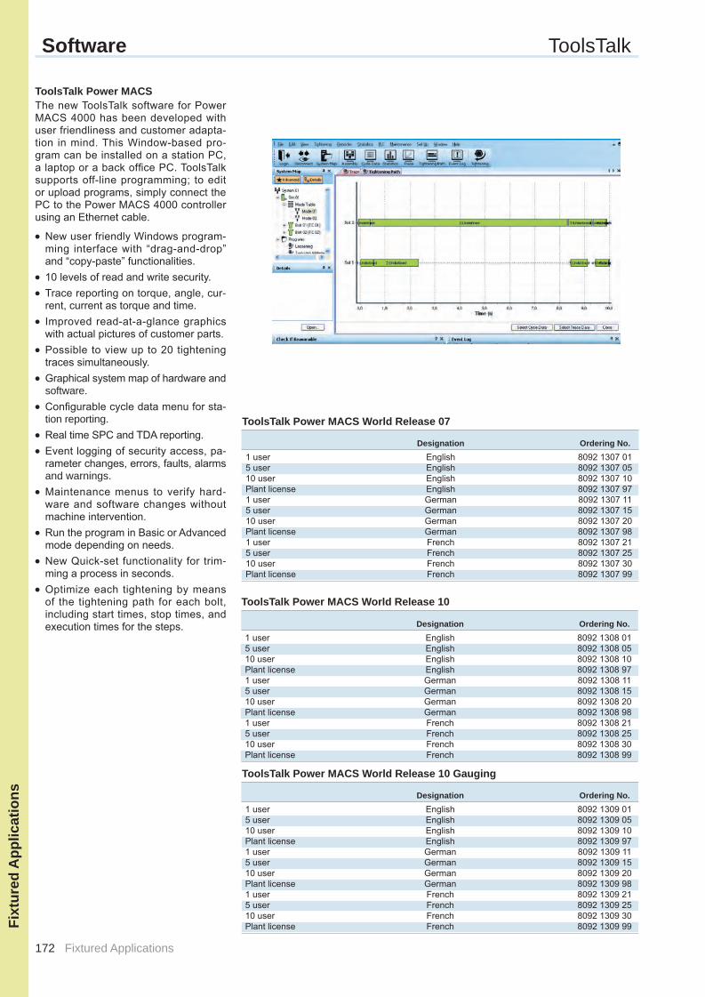
Fi
xtur
ed A
pplic
atio
ns
172 Fixtured Applications
Designation Ordering No.1 user English 8092 1307 015 user English 8092 1307 0510 user English 8092 1307 10Plant license English 8092 1307 971 user German 8092 1307 115 user German 8092 1307 1510 user German 8092 1307 20Plant license German 8092 1307 981 user French 8092 1307 215 user French 8092 1307 2510 user French 8092 1307 30Plant license French 8092 1307 99
ToolsTalk Power MACS World Release 07
Software ToolsTalk
ToolsTalk Power MACSThe new ToolsTalk software for Power MACS 4000 has been developed with user friendliness and customer adapta-tion in mind. This Window-based pro-gram can be installed on a station PC, a laptop or a back office PC. ToolsTalk supports off-line programming; to edit or upload programs, simply connect the PC to the Power MACS 4000 controller using an Ethernet cable.
l New user friendly Windows program-ming interface with “drag-and-drop” and “copy-paste” functionalities.
l 10 levels of read and write security.l Trace reporting on torque, angle, cur-
rent, current as torque and time.l Improved read-at-a-glance graphics
with actual pictures of customer parts.l Possible to view up to 20 tightening
traces simultaneously.l Graphical system map of hardware and
software.l Configurable cycle data menu for sta-
tion reporting.l Real time SPC and TDA reporting.l Event logging of security access, pa-
rameter changes, errors, faults, alarms and warnings.
l Maintenance menus to verify hard-ware and software changes without machine intervention.
l Run the program in Basic or Advanced mode depending on needs.
l New Quick-set functionality for trim-ming a process in seconds.
l Optimize each tightening by means of the tightening path for each bolt, including start times, stop times, and execution times for the steps. Designation Ordering No.
1 user English 8092 1308 015 user English 8092 1308 0510 user English 8092 1308 10Plant license English 8092 1308 971 user German 8092 1308 115 user German 8092 1308 1510 user German 8092 1308 20Plant license German 8092 1308 981 user French 8092 1308 215 user French 8092 1308 2510 user French 8092 1308 30Plant license French 8092 1308 99
ToolsTalk Power MACS World Release 10
Designation Ordering No.1 user English 8092 1309 015 user English 8092 1309 0510 user English 8092 1309 10Plant license English 8092 1309 971 user German 8092 1309 115 user German 8092 1309 1510 user German 8092 1309 20Plant license German 8092 1309 981 user French 8092 1309 215 user French 8092 1309 2510 user French 8092 1309 30Plant license French 8092 1309 99
ToolsTalk Power MACS World Release 10 Gauging
Am_Fixturedapplications.indd 172 2012-02-07 10:12:39

Contents PageSTanalyser .........................................175QRTT transducers .............................178IRTT-B transducers ...........................178SRTT-B transducers .........................179MRTT-C transducers ........................180ACTA MT transducers .......................181STwrench ..........................................183BLM TPT, μ-Tester .............................189BLM Joint Simulator Bench AD .........190ToolsTalk QAT ....................................191
Quality Assurance in Tightening
Am_Qualityasstight.indd 173 2012-02-06 14:21:42

Q
ualit
y A
ssur
ance
in T
ight
enin
g
174 Quality Assurance in Tightening
Quality assurance that gives peace of mind
Atlas Copco’s tightening quality assur-ance system meets torque, angle and pulse measurement requirements for all types of fastening tools and joint verifi-cation through the residual torque check process.
In this range there are products that en-able you to:l Test the tool capability in the crib or
along the line.l Calibrate the tool in the fastest, most
convenient way.l Perform statistical process control of
the performance of the tool along the line to prevent possible tool error.
l Check the residual torque in an al-ready tightened joint with an advanced algorithm to avoid operator error and influence.
Data analyser plus rotary and static transducerThe STanalyser provides a complete range of systems for checking the tool in the tool crib or along the line. When connected with the wrench MRTT-C the STanalyser makes able the detection of the residual torque on an already tight-ened joint using our patented algorithm used also in the STwrench.
Introduction – Quality Assurance in Tightening
STwrench State-of-the-art, four-patent wrench that employs the modularity concept to check the residual torque on an already tight-ened joint. It can also be used to tighten a bolt with the most advanced torque or torque/angle strategies with complete traceability and error-proofing function-alities.
BenchesA full range of Joint Simulator Benches with a patented system for testing tools in real production conditions, or Static transducer benches as an all-in-one mo-bile system.
SoftwareTorque Supervisor is Quality Manage-ment software to manage your Tool/Joint test and your maintenance activity. It can be used with benches, wrenches and data analyser.
Problems related to tightening account for a growing percentage of total warranty costs. A loose or improperly tightened joint in any assembly operation can cause serious problems and have serious consequences for end-users and result in damaged brand image for the manufacturer. Atlas Copco has developed a comprehensive quality assurance system designed to eliminates these problems.
Am_Qualityasstight.indd 174 2012-02-06 14:21:55
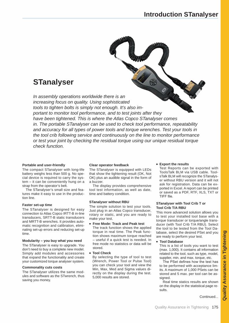
Qua
lity
Ass
uran
ce in
Tig
hten
ing
Quality Assurance in Tightening 175
Introduction STanalyser
In assembly operations worldwide there is an increasing focus on quality. Using sophisticated tools to tighten bolts is simply not enough. It’s also im-portant to monitor tool performance, and to test joints after they have been tightened. This is where the Atlas Copco STanalyser comes in. The portable STanalyser can be used to check tool performance, repeatability and accuracy for all types of power tools and torque wrenches. Test your tools in the tool crib following service and continuously on the line to monitor performance or test your joint by checking the residual torque using our unique residual torque check function.
Portable and user-friendlyThe compact STanalyser with long-life battery weighs less than 500 g. No spe-cial device is required to carry the sys-tem – it can be conveniently hung on a strap from the operator’s belt.
The STanalyser’s small size and fea-tures make it easy to use in the produc-tion line.
Faster set-up timeThe STanalyser is designed for easy connection to Atlas Copco IRTT-B in-line transducers, SRTT-B static transducers and MRTT-B wrenches. It provides auto-matic recognition and calibration, elimi-nating set-up errors and reducing set-up time.
Modularity – you buy what you needThe STanalyser is easy to upgrade. You don’t need to buy a complete new model. Simply add modules and accessories that expand the functionality and create your customized torque analyser system.
Commonality cuts costsThe STanalyser utilizes the same mod-ules and software as the STwrench, thus saving you money.
Clear operator feedbackThe STanalyser is equipped with LEDs that show the tightening result (OK, Not OK) plus an audible signal in the form of a buzzer.
The display provides comprehensive tool test information, as well as date, time and battery condition.
STanalyser without RBUThe simple solution to test your tools. Just plug in an Atlas Copco transducer, rotary or static, and you are ready to make your test.l Free Mode: Track and Peak test The track function shows the applied
torque in real time. The Peak func-tion shows maximum torque reached – useful if a quick test is needed. In free mode no statistics or data will be stored.
l Tool Check By selecting the type of tool to test
(Wrench, Power Tool or Pulse Tool) you can check your tool and view the Min, Max, Med and Sigma values di-rectly on the display during the test. 5,000 results are stored.
STanalyser
l Export the results Test Reports can be exported with
ToolsTalk BLM via USB cable. Tool-sTalk BLM will recognize the STanalys-er without RBU version and it will not ask for registration. Data can be ex-ported in Excel. A report can be printed or saved as a PDF, RTF, XLS, TXT or TIFF file.
STanalyser with Tool Crib T or Tool Crib T/A RBUThis more advanced solution allows you to test your installed tool base with a torque transducer or torque/angle trans-ducer (with Tool Crib T/A RBU). Select the tool to be tested from the Tool Da-tabase, select the desired PSet and you are ready to perform your test.l Tool Database This is a list of tools you want to test
(max. 1,000). It contains all information related to the tool, such as type, model, supplier, min. and max. torque, etc.
The PSet defines how the test has to be performed with acceptance lim-its. A maximum of 1,000 PSets can be stored and 5 max. per tool can be as-signed.
Real time statics results are shown on the display in the statistical page re-sults.
Continued...
Am_Qualityasstight.indd 175 2012-02-06 14:21:58
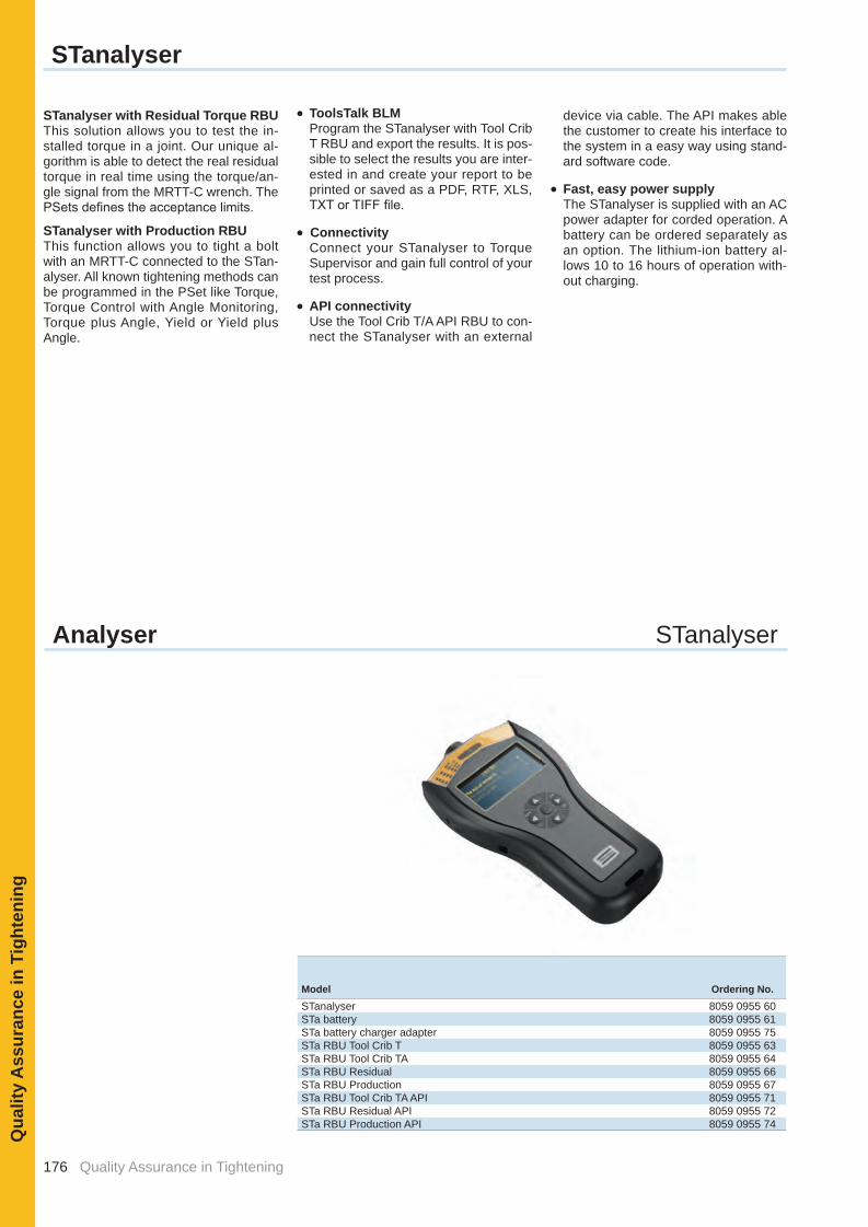
Q
ualit
y A
ssur
ance
in T
ight
enin
g
176 Quality Assurance in Tightening
STanalyser with Residual Torque RBUThis solution allows you to test the in-stalled torque in a joint. Our unique al-gorithm is able to detect the real residual torque in real time using the torque/an-gle signal from the MRTT-C wrench. The PSets defi nes the acceptance limits.
STanalyser with Production RBUThis function allows you to tight a bolt with an MRTT-C connected to the STan-alyser. All known tightening methods can be programmed in the PSet like Torque, Torque Control with Angle Monitoring, Torque plus Angle, Yield or Yield plus Angle.
STanalyser
Model Ordering No.STanalyser 8059 0955 60STa battery 8059 0955 61STa battery charger adapter 8059 0955 75STa RBU Tool Crib T 8059 0955 63STa RBU Tool Crib TA 8059 0955 64STa RBU Residual 8059 0955 66STa RBU Production 8059 0955 67STa RBU Tool Crib TA API 8059 0955 71STa RBU Residual API 8059 0955 72STa RBU Production API 8059 0955 74
Analyser STanalyser
l ToolsTalk BLM Program the STanalyser with Tool Crib
T RBU and export the results. It is pos-sible to select the results you are inter-ested in and create your report to be printed or saved as a PDF, RTF, XLS, TXT or TIFF fi le.
l Connectivity Connect your STanalyser to Torque
Supervisor and gain full control of your test process.
l API connectivity Use the Tool Crib T/A API RBU to con-
nect the STanalyser with an external
device via cable. The API makes able the customer to create his interface to the system in a easy way using stand-ard software code.
l Fast, easy power supply The STanalyser is supplied with an AC
power adapter for corded operation. A battery can be ordered separately as an option. The lithium-ion battery al-lows 10 to 16 hours of operation with-out charging.
Am_Qualityasstight.indd 176 2012-02-06 14:22:04
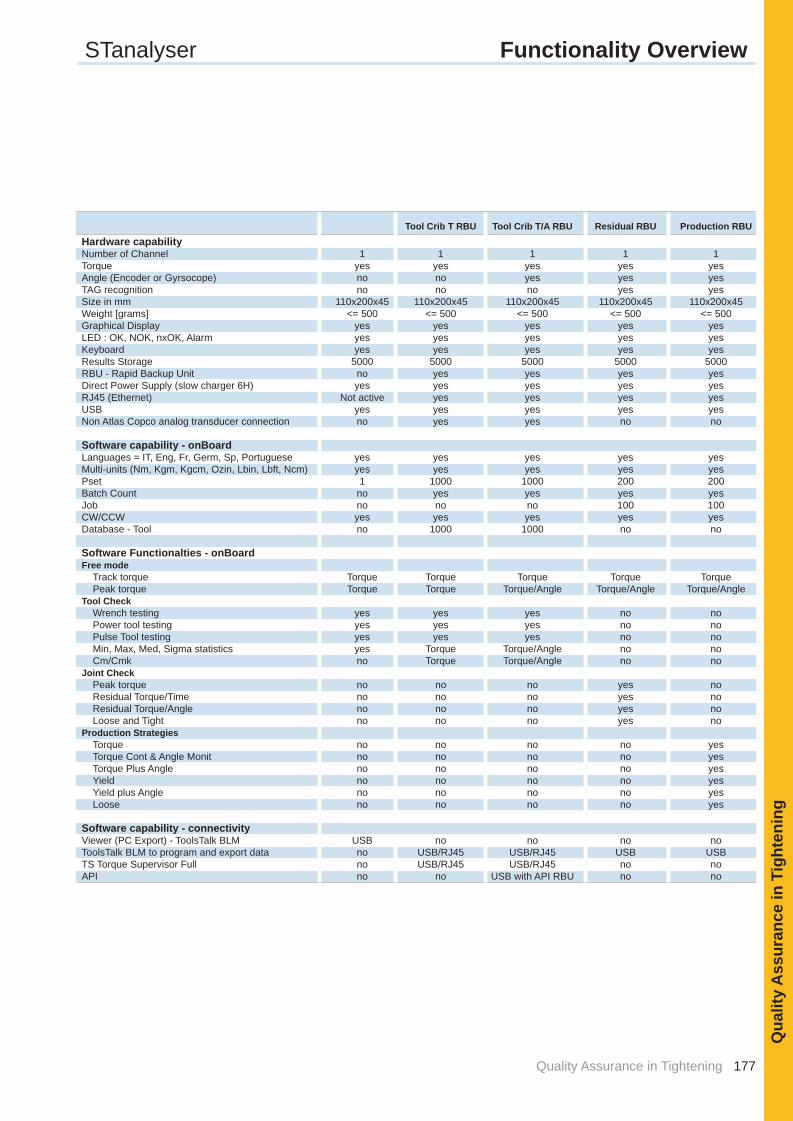
Qua
lity
Ass
uran
ce in
Tig
hten
ing
Quality Assurance in Tightening 177
STanalyser Functionality Overview
Tool Crib T RBU Tool Crib T/A RBU Residual RBU Production RBUHardware capability Number of Channel 1 1 1 1 1Torque yes yes yes yes yesAngle (Encoder or Gyrsocope) no no yes yes yesTAG recognition no no no yes yesSize in mm 110x200x45 110x200x45 110x200x45 110x200x45 110x200x45Weight [grams] <= 500 <= 500 <= 500 <= 500 <= 500Graphical Display yes yes yes yes yesLED : OK, NOK, nxOK, Alarm yes yes yes yes yesKeyboard yes yes yes yes yesResults Storage 5000 5000 5000 5000 5000RBU - Rapid Backup Unit no yes yes yes yesDirect Power Supply (slow charger 6H) yes yes yes yes yesRJ45 (Ethernet) Not active yes yes yes yesUSB yes yes yes yes yesNon Atlas Copco analog transducer connection no yes yes no no
Software capability - onBoard Languages = IT, Eng, Fr, Germ, Sp, Portuguese yes yes yes yes yesMulti-units (Nm, Kgm, Kgcm, Ozin, Lbin, Lbft, Ncm) yes yes yes yes yesPset 1 1000 1000 200 200Batch Count no yes yes yes yesJob no no no 100 100CW/CCW yes yes yes yes yesDatabase - Tool no 1000 1000 no no
Software Functionalties - onBoard Free mode
Track torque Torque Torque Torque Torque TorquePeak torque Torque Torque Torque/Angle Torque/Angle Torque/Angle
Tool Check Wrench testing yes yes yes no noPower tool testing yes yes yes no noPulse Tool testing yes yes yes no noMin, Max, Med, Sigma statistics yes Torque Torque/Angle no noCm/Cmk no Torque Torque/Angle no no
Joint Check Peak torque no no no yes noResidual Torque/Time no no no yes noResidual Torque/Angle no no no yes noLoose and Tight no no no yes no
Production Strategies Torque no no no no yesTorque Cont & Angle Monit no no no no yesTorque Plus Angle no no no no yesYield no no no no yesYield plus Angle no no no no yesLoose no no no no yes
Software capability - connectivity Viewer (PC Export) - ToolsTalk BLM USB no no no noToolsTalk BLM to program and export data no USB/RJ45 USB/RJ45 USB USBTS Torque Supervisor Full no USB/RJ45 USB/RJ45 no noAPI no no USB with API RBU no no
Am_Qualityasstight.indd 177 2012-02-06 14:22:04
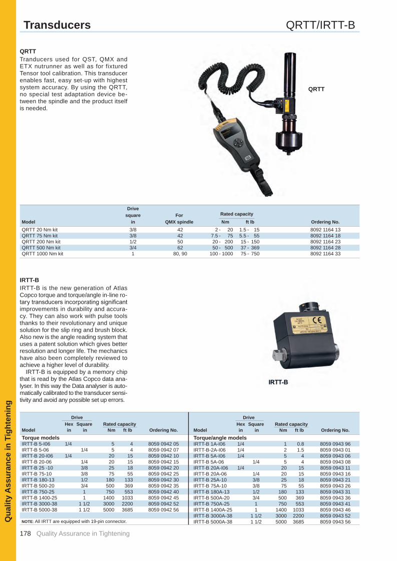
Q
ualit
y A
ssur
ance
in T
ight
enin
g
178 Quality Assurance in Tightening
QRTT
Transducers QRTT/IRTT-B
NOTE: All IRTT are equipped with 19-pin connector.
Drive Hex Square Rated capacityModel in in Nm ft lb Ordering No.Torque modelsIRTT-B 5-I06 1/4 5 4 8059 0942 05IRTT-B 5-06 1/4 5 4 8059 0942 07IRTT-B 20-I06 1/4 20 15 8059 0942 10IRTT-B 20-06 1/4 20 15 8059 0942 15IRTT-B 25 -10 3/8 25 18 8059 0942 20IRTT-B 75-10 3/8 75 55 8059 0942 25IRTT-B 180-13 1/2 180 133 8059 0942 30IRTT-B 500-20 3/4 500 369 8059 0942 35IRTT-B 750-25 1 750 553 8059 0942 40IRTT-B 1400-25 1 1400 1033 8059 0942 45IRTT-B 3000-38 1 1/2 3000 2200 8059 0942 52IRTT-B 5000-38 1 1/2 5000 3685 8059 0942 56
Drive Hex Square Rated capacityModel in in Nm ft lb Ordering No.Torque/angle modelsIRTT-B 1A-I06 1/4 1 0.8 8059 0943 96IRTT-B-2A-I06 1/4 2 1.5 8059 0943 01IRTT-B 5A-I06 1/4 5 4 8059 0943 06IRTT-B 5A-06 1/4 5 4 8059 0943 08IRTT-B 20A-I06 1/4 20 15 8059 0943 11IRTT-B 20A-06 1/4 20 15 8059 0943 16IRTT-B 25A-10 3/8 25 18 8059 0943 21IRTT-B 75A-10 3/8 75 55 8059 0943 26IRTT-B 180A-13 1/2 180 133 8059 0943 31IRTT-B 500A-20 3/4 500 369 8059 0943 36IRTT-B 750A-25 1 750 553 8059 0943 41IRTT-B 1400A-25 1 1400 1033 8059 0943 46IRTT-B 3000A-38 1 1/2 3000 2200 8059 0943 52IRTT-B 5000A-38 1 1/2 5000 3685 8059 0943 56
IRTT-BIRTT-B is the new generation of Atlas Copco torque and torque/angle in-line ro-tary transducers incorporating signifi cant improvements in durability and accura-cy. They can also work with pulse tools thanks to their revolutionary and unique solution for the slip ring and brush block. Also new is the angle reading system that uses a patent solution which gives better resolution and longer life. The mechanics have also been completely reviewed to achieve a higher level of durability.
IRTT-B is equipped by a memory chip that is read by the Atlas Copco data ana-lyser. In this way the Data analyser is auto-matically calibrated to the transducer sensi-tivity and avoid any possible set up errors.
Drive square For Rated capacityModel in QMX spindle Nm ft lb Ordering No.QRTT 20 Nm kit 3/8 42 2 - 20 1.5 - 15 8092 1164 13QRTT 75 Nm kit 3/8 42 7.5 - 75 5.5 - 55 8092 1164 18QRTT 200 Nm kit 1/2 50 20 - 200 15 - 150 8092 1164 23QRTT 500 Nm kit 3/4 62 50 - 500 37 - 369 8092 1164 28QRTT 1000 Nm kit 1 80, 90 100 - 1000 75 - 750 8092 1164 33
QRTTTranducers used for QST, QMX and ETX nutrunner as well as for fixtured Tensor tool calibration. This transducer enables fast, easy set-up with highest system accuracy. By using the QRTT, no special test adaptation device be-tween the spindle and the product itself is needed.
Am_Qualityasstight.indd 178 2012-02-06 14:22:06
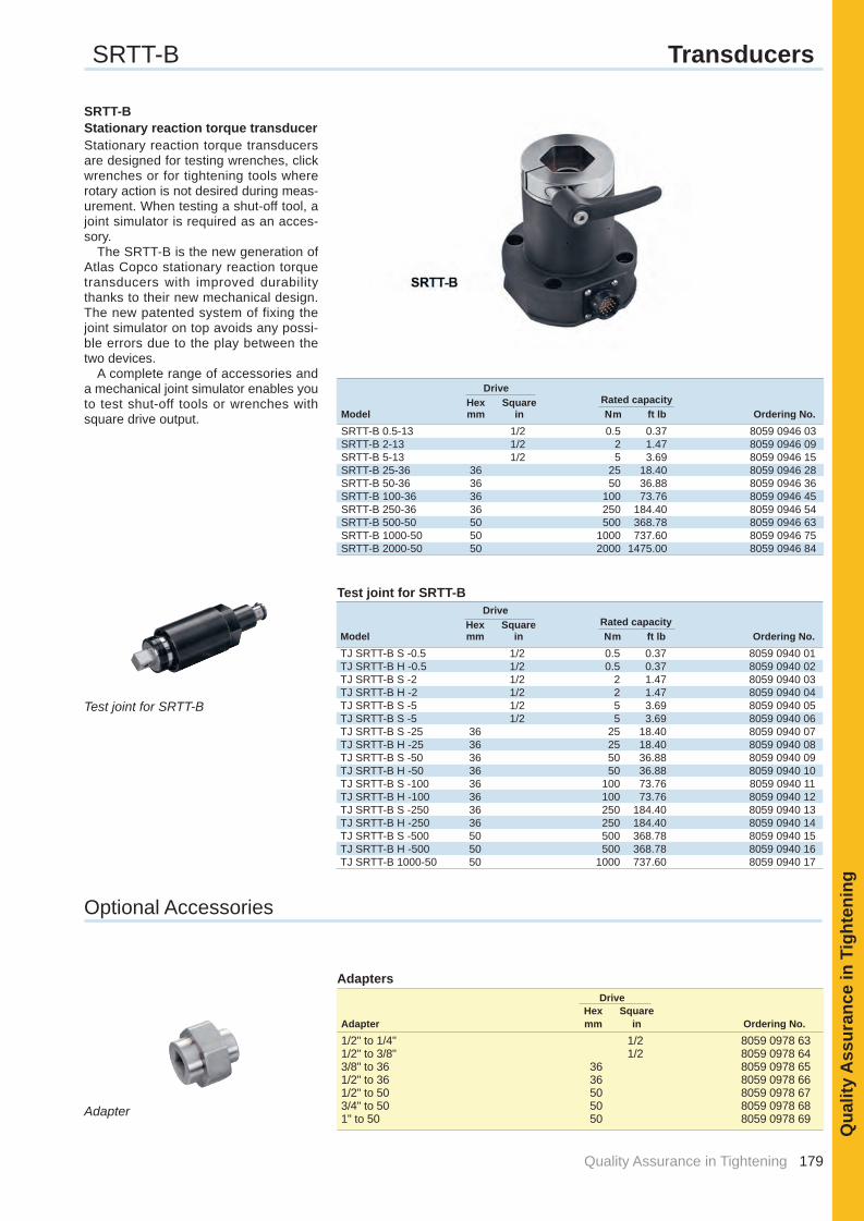
Qua
lity
Ass
uran
ce in
Tig
hten
ing
Quality Assurance in Tightening 179
SRTT-B Transducers
SRTT-BStationary reaction torque transducerStationary reaction torque transducers are designed for testing wrenches, click wrenches or for tightening tools where rotary action is not desired during meas-urement. When testing a shut-off tool, a joint simulator is required as an acces-sory.
The SRTT-B is the new generation of Atlas Copco stationary reaction torque transducers with improved durability thanks to their new mechanical design. The new patented system of fixing the joint simulator on top avoids any possi-ble errors due to the play between the two devices.
A complete range of accessories and a mechanical joint simulator enables you to test shut-off tools or wrenches with square drive output.
Drive Hex Square Rated capacity Model mm in Nm ft lb Ordering No.SRTT-B 0.5-13 1/2 0.5 0.37 8059 0946 03SRTT-B 2-13 1/2 2 1.47 8059 0946 09SRTT-B 5-13 1/2 5 3.69 8059 0946 15SRTT-B 25-36 36 25 18.40 8059 0946 28SRTT-B 50-36 36 50 36.88 8059 0946 36SRTT-B 100-36 36 100 73.76 8059 0946 45SRTT-B 250-36 36 250 184.40 8059 0946 54SRTT-B 500-50 50 500 368.78 8059 0946 63SRTT-B 1000-50 50 1000 737.60 8059 0946 75SRTT-B 2000-50 50 2000 1475.00 8059 0946 84
Drive Hex Square Rated capacity Model mm in Nm ft lb Ordering No.TJ SRTT-B S -0.5 1/2 0.5 0.37 8059 0940 01TJ SRTT-B H -0.5 1/2 0.5 0.37 8059 0940 02TJ SRTT-B S -2 1/2 2 1.47 8059 0940 03TJ SRTT-B H -2 1/2 2 1.47 8059 0940 04TJ SRTT-B S -5 1/2 5 3.69 8059 0940 05TJ SRTT-B S -5 1/2 5 3.69 8059 0940 06TJ SRTT-B S -25 36 25 18.40 8059 0940 07TJ SRTT-B H -25 36 25 18.40 8059 0940 08TJ SRTT-B S -50 36 50 36.88 8059 0940 09TJ SRTT-B H -50 36 50 36.88 8059 0940 10TJ SRTT-B S -100 36 100 73.76 8059 0940 11TJ SRTT-B H -100 36 100 73.76 8059 0940 12TJ SRTT-B S -250 36 250 184.40 8059 0940 13TJ SRTT-B H -250 36 250 184.40 8059 0940 14TJ SRTT-B S -500 50 500 368.78 8059 0940 15TJ SRTT-B H -500 50 500 368.78 8059 0940 16TJ SRTT-B 1000-50 50 1000 737.60 8059 0940 17
Test joint for SRTT-B
Drive Hex Square Adapter mm in Ordering No.1/2" to 1/4" 1/2 8059 0978 631/2" to 3/8" 1/2 8059 0978 643/8" to 36 36 8059 0978 651/2" to 36 36 8059 0978 661/2" to 50 50 8059 0978 673/4" to 50 50 8059 0978 681" to 50 50 8059 0978 69
Optional Accessories
Test joint for SRTT-B
Adapter
Adapters
Am_Qualityasstight.indd 179 2012-02-06 14:22:09
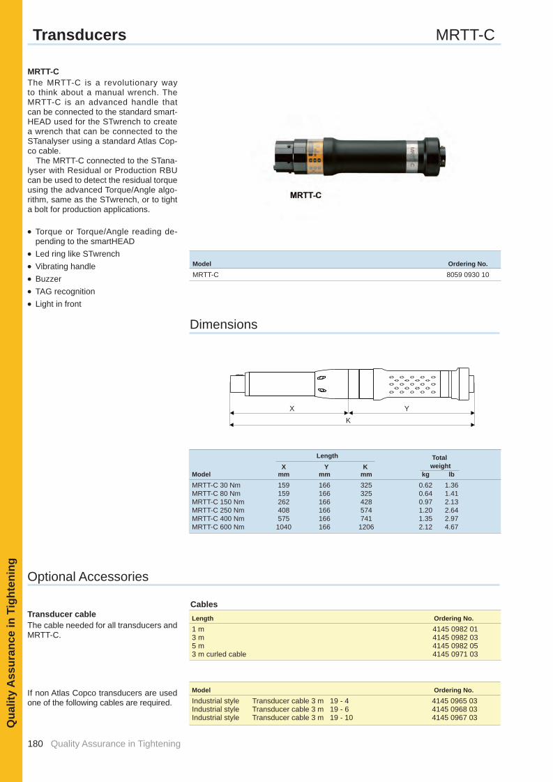
Q
ualit
y A
ssur
ance
in T
ight
enin
g
180 Quality Assurance in Tightening
X YK
Length Ordering No.1 m 4145 0982 013 m 4145 0982 035 m 4145 0982 053 m curled cable 4145 0971 03
Model Ordering No.Industrial style Transducer cable 3 m 19 - 4 4145 0965 03Industrial style Transducer cable 3 m 19 - 6 4145 0968 03Industrial style Transducer cable 3 m 19 - 10 4145 0967 03
Transducer cableThe cable needed for all transducers and MRTT-C.
If non Atlas Copco transducers are used one of the following cables are required.
Cables
Optional Accessories
Dimensions
Model Ordering No.MRTT-C 8059 0930 10
Length Total X Y K weightModel mm mm mm kg lbMRTT-C 30 Nm 159 166 325 0.62 1.36MRTT-C 80 Nm 159 166 325 0.64 1.41MRTT-C 150 Nm 262 166 428 0.97 2.13MRTT-C 250 Nm 408 166 574 1.20 2.64MRTT-C 400 Nm 575 166 741 1.35 2.97MRTT-C 600 Nm 1040 166 1206 2.12 4.67
MRTT-CThe MRTT-C is a revolutionary way to think about a manual wrench. The MRTT-C is an advanced handle that can be connected to the standard smart-HEAD used for the STwrench to create a wrench that can be connected to the STanalyser using a standard Atlas Cop-co cable.
The MRTT-C connected to the STana-lyser with Residual or Production RBU can be used to detect the residual torque using the advanced Torque/Angle algo-rithm, same as the STwrench, or to tight a bolt for production applications.
l Torque or Torque/Angle reading de-pending to the smartHEAD
l Led ring like STwrenchl Vibrating handlel Buzzerl TAG recognitionl Light in front
Transducers MRTT-C
Am_Qualityasstight.indd 180 2012-02-06 14:22:10

Qua
lity
Ass
uran
ce in
Tig
hten
ing
Quality Assurance in Tightening 181
MicroTorque Transducers and Analyzer
Quality assurance system – sharpen-ing your competitive edgeTo ensure the highest quality of your fas-tening – and ultimately your company’s products – Atlas Copco has developed a comprehensive quality assurance sys-tem for micro torques. The controller-cable-transducer package provides fast, accurate and reliable measurement of critical parameters.
ACTA MT4 – smart new featuresl Connect to PC via USB/RS232/Ether-
net.l 16 different engineering units to
choose from.l Colour configurable display (Torque/
Angle/ Status/Trace).l Battery for portable usage.l Programmable via keypad or software “ToolsTalk ACTA MT”.l Dual transducer inputs.l High resolution OLED colour display.l Audio signal for operator feedback.l Digital I/O signals for communication
with external devices such as PLC.l ESD grounding terminal.
Capacity Overall length Model Ncm in lb Drive mm Ordering No.Manual screwdriver torque transducerMT TH 1 1.0 0.09 Ø 3 mm 115 8432 0820 10MT TH 2 2.0 0.18 Ø 3 mm 115 8432 0820 11MT TH 5 5.0 0.44 Ø 3 mm 115 8432 0820 12MT TH 10 10.0 0.88 Ø 3 mm 115 8432 0820 13MT TH 20 20.0 1.77 1/4" 115 8432 0820 14MT TH 50 50.0 4.42 1/4" 124 8432 0820 15MT TH 100 100.0 8.85 1/4" 124 8432 0820 16MT TH 200 200.0 17.70 1/4" 124 8432 0820 17Stationary reaction torque transducer MT TS 1 1.0 0.09 Ø 3 mm 81 8432 0820 18MT TS 2 2.0 0.18 Ø 3 mm 81 8432 0820 19MT TS 5 5.0 0.44 Ø 3 mm 81 8432 0820 20MT TS 10 10.0 0.88 Ø 3 mm 81 8432 0820 21MT TS 20 20.0 1.77 Ø 3 mm 81 8432 0820 22MT TS 50 50.0 4.42 1/4" 98 8432 0820 23MT TS 100 100.0 8.85 1/4" 98 8432 0820 24MT TS 200 200.0 17.70 1/4" 98 8432 0820 25MT TS 500 500.0 44.25 1/4" 111 8432 0820 52In-line rotary torque and angle transducer MT TRA 2 2.0 0.18 Ø 3 mm 76 8432 0820 41MT TRA 5 5.0 0.44 Ø 3 mm 76 8432 0820 42MT TRA 10 10.0 0.88 Ø 5 mm 76 8432 0820 43MT TRA 20 20.0 1.77 Ø 5 mm 76 8432 0820 44MT TRA 50 50.0 4.42 1/4" 105 8432 0820 45MT TRA 100 100.0 8.85 1/4" 105 8432 0820 46MT TRA 200 200.0 17.70 1/4" 105 8432 0820 47MT TRA 500 500.0 44.25 1/4" 105 8432 0820 48
Am_Qualityasstight.indd 181 2012-02-06 14:22:11

Q
ualit
y A
ssur
ance
in T
ight
enin
g
182 Quality Assurance in Tightening
Torque analyzer
Model Ordering No.
ACTA MT 4a (programable over keypad) 8432 0820 04ToolsTalk MT Analysis (trace analysis) 8432 0830 31Transducer cable 8432 0830 35RS232 cable ACTA MT 8432 0831 39
Model Ordering No.
Lens head screw DIN7985 PH0 M1.6x4 V2A PH0 4023 0005 01 ISO14583 TX6 M2,0x10 V2A TX6 4023 0005 02 ISO14583 TX8 M2,5x10 V2A TX8 4023 0005 03 ISO14583 TX10 M3,0x10 V2A TX10 4023 0005 04 ISO14583 TX20 M4,0x12 V2A TX20 4023 0005 05 ISO14583 TX25 M5,0x12 V2A TX25 4023 0005 06 ISO14583 TX30 M6,0x12 V2A TX30 4023 0005 07
Fasteners for joint kits
Stationary torque transducers, accessories
Accessories MicroTorque
Stationarytransducer
Joint kit
FasteneraToolsTalk ACTA MT (programming software) included
Model Ordering No.
Joint Kit M1.6 for MT TS - 3H7 adapter (up to 20 Ncm) 8432 0830 79 M2 for MT TS - 1/4" adapter (up to 50 Ncm) 8432 0830 78 M2.5 for MT TS- 1/4" adapter (up to 100 Ncm) 8432 0830 77 M3.0 for MT TS- 1/4" adapter (up to 200 Ncm) 8432 0830 87 M4.0 for MT TS- 1/4" adapter (up to 300 Ncm) 8432 0830 86 M5.0 for MT TS- 1/4" adapter (up to 600 Ncm) 8432 0830 85 M6.0 for MT TS- 1/4" adapter (up to 800 Ncm) 8432 0832 67
Test joints for calibration with MT TSModel Designation Range, Ncm Ordering No.Test joint M6 Soft joint 1/4" HEX 500 - 1000 8432 0833 62 M6 Soft joint 1/4" HEX 200 - 500 8432 0833 61 M4 Soft joint 1/4" HEX 27 - 200 8432 0833 60 M3 Soft joint 1/4" HEX 5 - 27 8432 0833 59 M3 Soft joint HM 5 - 27 8432 0833 58 M2 Soft joint 1/4" HEX 0 - 10 8432 0833 57 M2 Soft joint HM 0 - 10 8432 0833 56 M6 Hard joint 1/4" HEX 200 - 1000 8432 0833 55 M4 Hard joint 1/4" HEX 27 - 200 8432 0833 54 M3 Hard joint 1/4" HEX 5 - 27 8432 0833 53 M3 Hard joint HM 5 - 27 8432 0833 52 M2 Hard joint 1/4" HEX 0 - 10 8432 0833 51 M2 Hard joint HM 0 - 10 8432 0833 50
Am_Qualityasstight.indd 182 2012-02-06 14:22:11
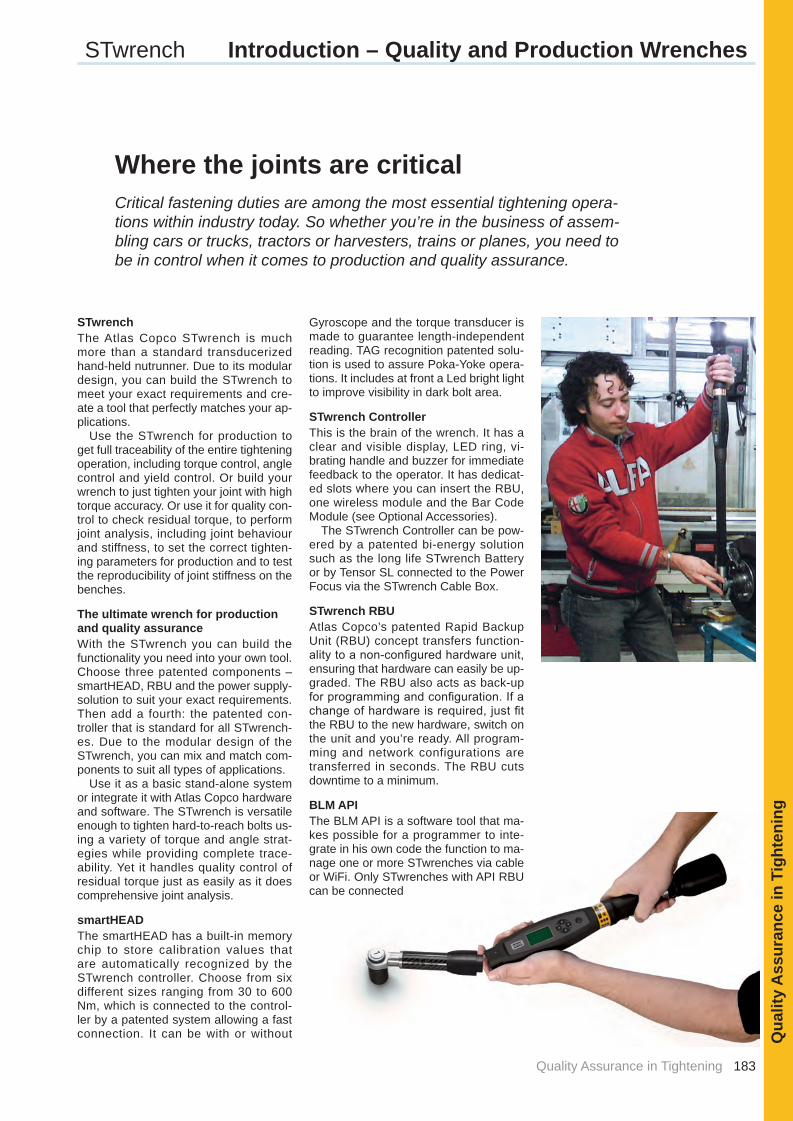
Qua
lity
Ass
uran
ce in
Tig
hten
ing
Quality Assurance in Tightening 183
STwrench Introduction – Quality and Production Wrenches
Where the joints are critical
STwrenchThe Atlas Copco STwrench is much more than a standard transducerized hand-held nutrunner. Due to its modular design, you can build the STwrench to meet your exact requirements and cre-ate a tool that perfectly matches your ap-plications.
Use the STwrench for production to get full traceability of the entire tightening operation, including torque control, angle control and yield control. Or build your wrench to just tighten your joint with high torque accuracy. Or use it for quality con-trol to check residual torque, to perform joint analysis, including joint behaviour and stiffness, to set the correct tighten-ing parameters for production and to test the reproducibility of joint stiffness on the benches.
The ultimate wrench for production and quality assuranceWith the STwrench you can build the functionality you need into your own tool. Choose three patented components – smartHEAD, RBU and the power supply-solution to suit your exact requirements. Then add a fourth: the patented con-troller that is standard for all STwrench-es. Due to the modular design of the STwrench, you can mix and match com-ponents to suit all types of applications.
Use it as a basic stand-alone system or integrate it with Atlas Copco hardware and software. The STwrench is versatile enough to tighten hard-to-reach bolts us-ing a variety of torque and angle strat-egies while providing complete trace-ability. Yet it handles quality control of residual torque just as easily as it does comprehensive joint analysis.
smartHEADThe smartHEAD has a built-in memory chip to store calibration values that are automatically recognized by the STwrench controller. Choose from six different sizes ranging from 30 to 600 Nm, which is connected to the control-ler by a patented system allowing a fast connection. It can be with or without
Gyroscope and the torque transducer is made to guarantee length-independent reading. TAG recognition patented solu-tion is used to assure Poka-Yoke opera-tions. It includes at front a Led bright light to improve visibility in dark bolt area.
STwrench ControllerThis is the brain of the wrench. It has a clear and visible display, LED ring, vi-brating handle and buzzer for immediate feedback to the operator. It has dedicat-ed slots where you can insert the RBU, one wireless module and the Bar Code Module (see Optional Accessories).
The STwrench Controller can be pow-ered by a patented bi-energy solution such as the long life STwrench Battery or by Tensor SL connected to the Power Focus via the STwrench Cable Box.
STwrench RBUAtlas Copco’s patented Rapid Backup Unit (RBU) concept transfers function-ality to a non-configured hardware unit, ensuring that hardware can easily be up-graded. The RBU also acts as back-up for programming and configuration. If a change of hardware is required, just fit the RBU to the new hardware, switch on the unit and you’re ready. All program-ming and network configurations are transferred in seconds. The RBU cuts downtime to a minimum.
BLM APIThe BLM API is a software tool that ma-kes possible for a programmer to inte-grate in his own code the function to ma-nage one or more STwrenches via cable or WiFi. Only STwrenches with API RBU can be connected
Critical fastening duties are among the most essential tightening opera-tions within industry today. So whether you’re in the business of assem-bling cars or trucks, tractors or harvesters, trains or planes, you need to be in control when it comes to production and quality assurance.
Am_Qualityasstight.indd 183 2012-02-06 14:22:16
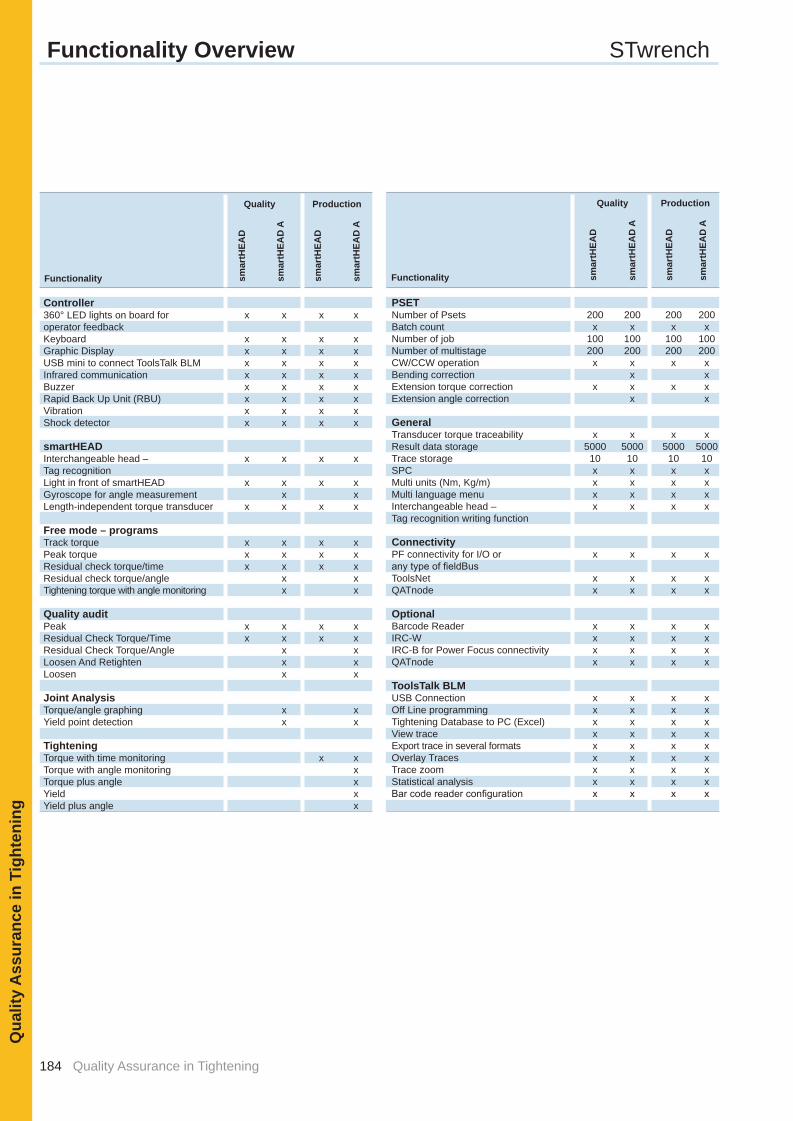
Q
ualit
y A
ssur
ance
in T
ight
enin
g
184 Quality Assurance in Tightening
Controller 360° LED lights on board for x x x xoperator feedbackKeyboard x x x x Graphic Display x x x x USB mini to connect ToolsTalk BLM x x x xInfrared communication x x x xBuzzer x x x xRapid Back Up Unit (RBU) x x x xVibration x x x xShock detector x x x x smartHEAD Interchangeable head – x x x x Tag recognition Light in front of smartHEAD x x x xGyroscope for angle measurement x xLength-independent torque transducer x x x x Free mode – programs Track torque x x x xPeak torque x x x xResidual check torque/time x x x xResidual check torque/angle x xTightening torque with angle monitoring x x Quality audit Peak x x x xResidual Check Torque/Time x x x xResidual Check Torque/Angle x xLoosen And Retighten x xLoosen x x Joint Analysis Torque/angle graphing x xYield point detection x x Tightening Torque with time monitoring x xTorque with angle monitoring xTorque plus angle xYield xYield plus angle x
Quality Production
Functionality smar
tHEA
D
smar
tHEA
D A
smar
tHEA
D
smar
tHEA
D A
Functionality Overview STwrench
Quality Production
Functionality smar
tHEA
D
smar
tHEA
D A
smar
tHEA
D
smar
tHEA
D A
PSET Number of Psets 200 200 200 200Batch count x x x xNumber of job 100 100 100 100Number of multistage 200 200 200 200CW/CCW operation x x x xBending correction x xExtension torque correction x x x xExtension angle correction x x General Transducer torque traceability x x x xResult data storage 5000 5000 5000 5000Trace storage 10 10 10 10SPC x x x xMulti units (Nm, Kg/m) x x x xMulti language menu x x x xInterchangeable head – x x x xTag recognition writing function
Connectivity PF connectivity for I/O or x x x xany type of fieldBusToolsNet x x x xQATnode x x x x
Optional Barcode Reader x x x xIRC-W x x x xIRC-B for Power Focus connectivity x x x xQATnode x x x x
ToolsTalk BLM USB Connection x x x xOff Line programming x x x xTightening Database to PC (Excel) x x x xView trace x x x xExport trace in several formats x x x xOverlay Traces x x x xTrace zoom x x x xStatistical analysis x x x xBar code reader configuration x x x x
Am_Qualityasstight.indd 184 2012-02-06 14:22:16
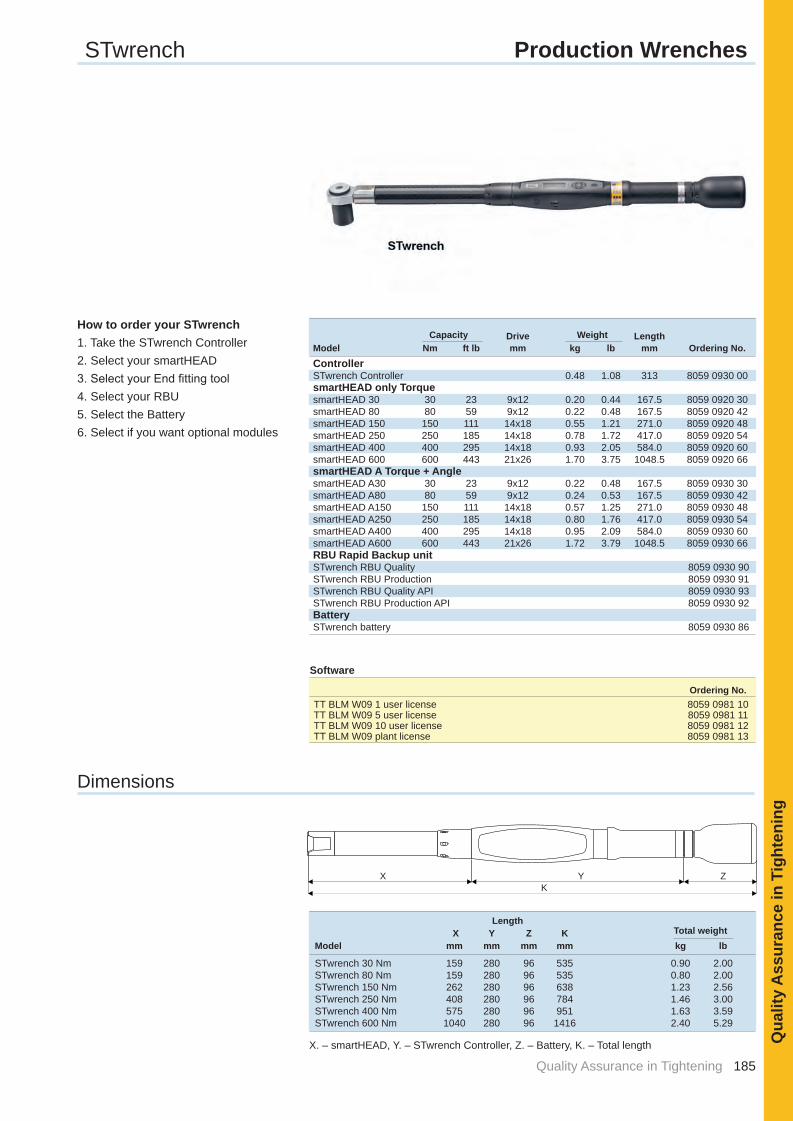
Qua
lity
Ass
uran
ce in
Tig
hten
ing
Quality Assurance in Tightening 185
X Y ZK
Capacity Drive Weight Length Model Nm ft lb mm kg lb mm Ordering No.ControllerSTwrench Controller 0.48 1.08 313 8059 0930 00smartHEAD only Torque smartHEAD 30 30 23 9x12 0.20 0.44 167.5 8059 0920 30smartHEAD 80 80 59 9x12 0.22 0.48 167.5 8059 0920 42smartHEAD 150 150 111 14x18 0.55 1.21 271.0 8059 0920 48smartHEAD 250 250 185 14x18 0.78 1.72 417.0 8059 0920 54smartHEAD 400 400 295 14x18 0.93 2.05 584.0 8059 0920 60smartHEAD 600 600 443 21x26 1.70 3.75 1048.5 8059 0920 66smartHEAD A Torque + Angle smartHEAD A30 30 23 9x12 0.22 0.48 167.5 8059 0930 30smartHEAD A80 80 59 9x12 0.24 0.53 167.5 8059 0930 42smartHEAD A150 150 111 14x18 0.57 1.25 271.0 8059 0930 48smartHEAD A250 250 185 14x18 0.80 1.76 417.0 8059 0930 54smartHEAD A400 400 295 14x18 0.95 2.09 584.0 8059 0930 60smartHEAD A600 600 443 21x26 1.72 3.79 1048.5 8059 0930 66RBU Rapid Backup unitSTwrench RBU Quality 8059 0930 90STwrench RBU Production 8059 0930 91STwrench RBU Quality API 8059 0930 93STwrench RBU Production API 8059 0930 92Battery STwrench battery 8059 0930 86
Length X Y Z K Total weight Model mm mm mm mm kg lb
STwrench 30 Nm 159 280 96 535 0.90 2.00STwrench 80 Nm 159 280 96 535 0.80 2.00STwrench 150 Nm 262 280 96 638 1.23 2.56STwrench 250 Nm 408 280 96 784 1.46 3.00STwrench 400 Nm 575 280 96 951 1.63 3.59STwrench 600 Nm 1040 280 96 1416 2.40 5.29
How to order your STwrench1. Take the STwrench Controller2. Select your smartHEAD3. Select your End fi tting tool4. Select your RBU5. Select the Battery6. Select if you want optional modules
Dimensions
X. – smartHEAD, Y. – STwrench Controller, Z. – Battery, K. – Total length
STwrench Production Wrenches
Software
Ordering No.TT BLM W09 1 user license 8059 0981 10TT BLM W09 5 user license 8059 0981 11TT BLM W09 10 user license 8059 0981 12TT BLM W09 plant license 8059 0981 13
Am_Qualityasstight.indd 185 2012-02-06 14:22:17

Q
ualit
y A
ssur
ance
in T
ight
enin
g
186 Quality Assurance in Tightening
IRC ModulesTwo different IRC modules each with dif-ferent wireless technology. No extra spe-cial software is needed, it is necessary only to plug in the new module to acti-vate the communication. The communi-cation can be to the Power Focus, to the QAT node, to the STwrench cradles or to different systems on the net.
Bar Code ModuleEnables the Bar Code to be read. STwrench is able to handle four different Bar Codes that can be used to activate or control the process and for traceability purposes. It is only necessary to plug in the module to activate the function.
STwrench batteryA Lithium ion battery that gives 16 h of working time (10 h if wireless communi-cation is used).
STwrench cable boxWired to connect the STwrench to the Power Focus using a standard Tensor SL cable. The STwrench cable box sup-plies power to the wrench and handles the communication between the wrench and the Power Focus.
STwrench battery chargerTo recharge the battery, it can be mount-ed in a horizontal or vertical position. It takes 4 hours to completely recharge the STwrench battery.
QATnodeThree different models of QATnode en-able the solution to be customized to specific needs. The QATnode can be connected to the STwrench in WiFi via access point, in real time connection, or via IrDa with wrench locked on the QAT-node, in non real time connection when wireless is not possible.
QATnode PUsed to print out a ticket result on a 40 column serial printer. The layout of the ticket is fully configurable via TT BLM.
QATnode I/OIn addition to QATnode P functionality it has 6 digital inputs and 5 digital outputs. All of them are fully configurable and it is possible to enable/disable the wrench, select a PSet or JOB and send out an OK or NOK.
QATnode TIn addition to STwrench PokaYoke func-tionality it makes it possible to send data to the ToolsNet server.
Ordering No.
STwrench IRC-B Module 8059 0920 10STwrench IRC-W Module 8059 0920 11
Ordering No.
Bar Code 8059 0920 12
Ordering No.
Battery charger 8059 0930 88
Ordering No.
Battery 8059 0930 86
Ordering No.
Cable box 8059 0920 24
PF, IRC focus & QIF accessoriesFor fieldbus connectivity and addition-al I/O port, or for backup station, the STwrench can be connected in wireless with PF or IRC Focus. It allow also the possibility to connect all QIF accessories such as stack light etc …
Ordering No.QATnode P 8059 0920 25QATnode I/O 8059 0920 26QATnode T 8059 0920 27
Accessories STwrench
IRC-module
Bar Code
Battery
Cable box
Battery charger
QATnode
Am_Qualityasstight.indd 186 2012-02-06 14:22:20
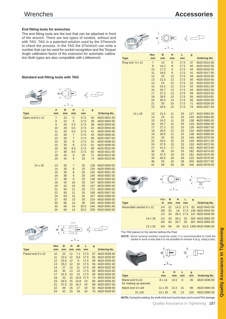
Qua
lity
Ass
uran
ce in
Tig
hten
ing
Quality Assurance in Tightening 187
B
L
H
602
W
B
L
H
602
W
H
604 - 704
B
LH
604 - 704
B
L
HA
L
606 - 706 - 806
HA
L
606 - 706 - 806
BH
L
601 -607 BH
L
601 -607
B A
L
H
600 - 700
B A
LH
600 - 700
A B H L g Type mm mm mm mm Ordering No. Open end 9 x 12 7 22 5 17.5 40 4620 0001 00 8 22 5 17.5 39 4620 0002 00 9 26 5.5 17.5 38 4620 0003 00 10 26 5.5 17.5 42 4620 0004 00 11 26 5.5 17.5 41 4620 0005 00 12 30 7 17.5 43 4620 0006 00 13 30 7 17.5 48 4620 0007 00 14 35 8 17.5 52 4620 0008 00 15 35 8 17.5 51 4620 0009 00 16 38 8.5 17.5 58 4620 0010 00 17 38 8.5 17.5 60 4620 0011 00 18 42 9 20 71 4620 0012 00 19 42 9 20 74 4620 0013 00
14 x 18 13 30 7 25 128 4620 0049 00 14 35 8 25 129 4620 0050 00 15 35 8 25 132 4620 0051 00 16 38 9 25 140 4620 0052 00 17 38 9 25 136 4620 0053 00 18 42 10 25 147 4620 0054 00 19 42 10 25 147 4620 0055 00 21 50 11 25 171 4620 0056 00 22 50 11 25 165 4620 0057 00 24 53 12 25 167 4620 0058 00 27 60 13 30 219 4620 0059 00 30 66 14 30 245 4620 0060 00 32 66 14 32.5 246 4620 0061 00 34 66 14 32.5 239 4620 0062 00
Hex B H L g Type mm mm mm mm Ordering No. Ring end 9 x 12 7 13 8 17.5 37 4620 0014 00 8 14.2 8 17.5 40 4620 0015 00 10 17.2 9 17.5 44 4620 0016 00 11 18.5 9 17.5 41 4620 0017 00 12 20 12 17.5 49 4620 0018 00 13 21.5 12 17.5 56 4620 0019 00 14 23 12 17.5 52 4620 0020 00 15 24.2 12 17.5 52 4620 0021 00 16 25.7 13 17.5 54 4620 0022 00 17 27.2 13 17.5 59 4620 0023 00 18 28.5 13 17.5 56 4620 0024 00 19 30.3 13 17.5 65 4620 0025 00 21 33 15 17.5 71 4620 0026 00 22 34.5 15 17.5 74 4620 0027 00
14 x 18 13 21.5 11 25 127 4620 0063 00 14 23 11 25 123 4620 0064 00 15 24.2 11 25 128 4620 0065 00 16 25.7 12 25 133 4620 0066 00 17 27.2 12 25 135 4620 0067 00 18 28.5 12 25 134 4620 0068 00 19 30.5 12 25 138 4620 0069 00 21 33 15 25 144 4620 0070 00 22 34.5 15 25 145 4620 0071 00 24 37.5 15 25 153 4620 0072 00 27 41.5 17 25 162 4620 0073 00 30 45 19 25 182 4620 0074 00 32 47.5 19 25 181 4620 0075 00 34 50.5 19 28 210 4620 0076 00 36 53 19 28 203 4620 0077 00 41 59 20 30 240 4620 0078 00
Hex B H W L g Type mm mm mm mm mm Ordering No.Flared end 9 x 12 10 22 12 7.1 17.5 57 4620 0028 00 11 22.5 12 8.6 17.5 55 4620 0029 00 12 23.5 12 9 17.5 59 4620 0030 00 13 25.2 12 10 17.5 55 4620 0031 00 14 27 13 11 17.5 60 4620 0032 00 16 30 13 13 17.5 65 4620 0033 00 17 31.5 13 14 17.5 65 4620 0034 00 18 33 15 14.8 17.5 74 4620 0035 00 19 34.5 15 15.8 19 80 4620 0036 00 21 37.5 15 16.2 19 88 4620 0037 00 22 39 15 17 19 92 4620 0038 00 24 42 15 18 19 75 4620 0039 00
Hex B H L g Type in mm mm mm Ordering No.Reversible ratchet 9 x 12 1/4 22 14.5 17.5 62 4620 0043 00 3/8 33 24 17.5 136 4620 0044 00 1/2 33 28.3 17.5 147 4620 0045 00 14 x 18 1/2 43 26.2 25 302 4620 0081 00 3/4 50 30.7 25 467 4620 0082 00 21 x 26 3/4 69 30 62.5 1350 4620 0086 00
A H L g Type mm mm mm mm Ordering No.Blank end 9 x12 8 x 14 14.5 8 30 4620 0048 00for making up specialsBlank end 14 x18 11 x 25 21.5 21 98 4620 0084 00 21 x26 13 x 30 30 13 220 4620 0085 00
NOTE: During the welding, the shaft of the tool must be kept cool to avoid TAG damage.
The TAG placed on the ratchet defines the Pset. NOTE: Since several sockets could be used, it is recommended to hold the
socket in such a way that it is not possible to remove it (e.g. using a pin).
Wrenches Accessories
Standard end fitting tools with TAG
End fitting tools for wrenches The end fitting tools are the tool that can be attached in front of the wrench. There are two types of models, without and with TAG. TAG is a patented solution used by the STwrench to check the process. In the TAG the STwrench can write a number that can be used for socket recognition and the Torque/Angle calibration factor of the extension for automatic calibra-tion Both types are also compatible with LABwrench.
Am_Qualityasstight.indd 187 2012-02-06 14:22:37
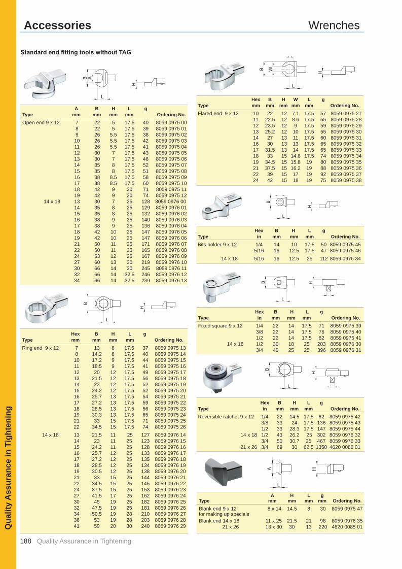
Q
ualit
y A
ssur
ance
in T
ight
enin
g
188 Quality Assurance in Tightening
B A
L
H
600 - 700
B A
L
H
600 - 700
BH
L
601 -607
BH
L
601 -607
B
L
H
605 - 705
B
L
H
605 - 705
BH
603 - 703
L
BH
603 - 703
LH
604 - 704
B
L
H
604 - 704
B
L
HA
L
606 - 706 - 806
HA
L
606 - 706 - 806
B
L
H
602
W
B
L
H
602
W
A B H L g Type mm mm mm mm Ordering No. Open end 9 x 12 7 22 5 17.5 40 8059 0975 00 8 22 5 17.5 39 8059 0975 01 9 26 5.5 17.5 38 8059 0975 02 10 26 5.5 17.5 42 8059 0975 03 11 26 5.5 17.5 41 8059 0975 04 12 30 7 17.5 43 8059 0975 05 13 30 7 17.5 48 8059 0975 06 14 35 8 17.5 52 8059 0975 07 15 35 8 17.5 51 8059 0975 08 16 38 8.5 17.5 58 8059 0975 09 17 38 8.5 17.5 60 8059 0975 10 18 42 9 20 71 8059 0975 11 19 42 9 20 74 8059 0975 12 14 x 18 13 30 7 25 128 8059 0976 00 14 35 8 25 129 8059 0976 01 15 35 8 25 132 8059 0976 02 16 38 9 25 140 8059 0976 03 17 38 9 25 136 8059 0976 04 18 42 10 25 147 8059 0976 05 19 42 10 25 147 8059 0976 06 21 50 11 25 171 8059 0976 07 22 50 11 25 165 8059 0976 08 24 53 12 25 167 8059 0976 09 27 60 13 30 219 8059 0976 10 30 66 14 30 245 8059 0976 11 32 66 14 32.5 246 8059 0976 12 34 66 14 32.5 239 8059 0976 13
Hex B H L g Type mm mm mm mm Ordering No. Ring end 9 x 12 7 13 8 17.5 37 8059 0975 13 8 14.2 8 17.5 40 8059 0975 14 10 17.2 9 17.5 44 8059 0975 15 11 18.5 9 17.5 41 8059 0975 16 12 20 12 17.5 49 8059 0975 17 13 21.5 12 17.5 56 8059 0975 18 14 23 12 17.5 52 8059 0975 19 15 24.2 12 17.5 52 8059 0975 20 16 25.7 13 17.5 54 8059 0975 21 17 27.2 13 17.5 59 8059 0975 22 18 28.5 13 17.5 56 8059 0975 23 19 30.3 13 17.5 65 8059 0975 24 21 33 15 17.5 71 8059 0975 25 22 34.5 15 17.5 74 8059 0975 26 14 x 18 13 21.5 11 25 127 8059 0976 14 14 23 11 25 123 8059 0976 15 15 24.2 11 25 128 8059 0976 16 16 25.7 12 25 133 8059 0976 17 17 27.2 12 25 135 8059 0976 18 18 28.5 12 25 134 8059 0976 19 19 30.5 12 25 138 8059 0976 20 21 33 15 25 144 8059 0976 21 22 34.5 15 25 145 8059 0976 22 24 37.5 15 25 153 8059 0976 23 27 41.5 17 25 162 8059 0976 24 30 45 19 25 182 8059 0976 25 32 47.5 19 25 181 8059 0976 26 34 50.5 19 28 210 8059 0976 27 36 53 19 28 203 8059 0976 28 41 59 20 30 240 8059 0976 29
Hex B H W L g Type mm mm mm mm mm Ordering No.Flared end 9 x 12 10 22 12 7.1 17.5 57 8059 0975 27 11 22.5 12 8.6 17.5 55 8059 0975 28 12 23.5 12 9 17.5 59 8059 0975 29 13 25.2 12 10 17.5 55 8059 0975 30 14 27 13 11 17.5 60 8059 0975 31 16 30 13 13 17.5 65 8059 0975 32 17 31.5 13 14 17.5 65 8059 0975 33 18 33 15 14.8 17.5 74 8059 0975 34 19 34.5 15 15.8 19 80 8059 0975 35 21 37.5 15 16.2 19 88 8059 0975 36 22 39 15 17 19 92 8059 0975 37 24 42 15 18 19 75 8059 0975 38
Hex B H L g Type in mm mm mm Ordering No. Fixed square 9 x 12 1/4 22 14 17.5 71 8059 0975 39 3/8 22 14 17.5 76 8059 0975 40 1/2 22 14 17.5 82 8059 0975 41 14 x 18 1/2 30 18 25 203 8059 0976 30 3/4 40 25 25 396 8059 0976 31
Hex B H L g Type in mm mm mm Ordering No. Reversible ratchet 9 x 12 1/4 22 14.5 17.5 62 8059 0975 42 3/8 33 24 17.5 136 8059 0975 43 1/2 33 28.3 17.5 147 8059 0975 44 14 x 18 1/2 43 26.2 25 302 8059 0976 32 3/4 50 30.7 25 467 8059 0976 33 21 x 26 3/4 69 30 62.5 1350 4620 0086 01
A H L g Type mm mm mm mm Ordering No.Blank end 9 x 12 8 x 14 14.5 8 30 8059 0975 47for making up specials Blank end 14 x 18 11 x 25 21.5 21 98 8059 0976 35 21 x 26 13 x 30 30 13 220 4620 0085 01
Hex B H L g Type in mm mm mm Ordering No. Bits holder 9 x 12 1/4 14 10 17.5 50 8059 0975 45 5/16 16 12.5 17.5 47 8059 0975 46 14 x 18 5/16 16 12.5 25 112 8059 0976 34
Standard end fitting tools without TAG
Accessories Wrenches
Am_Qualityasstight.indd 188 2012-02-06 14:23:02
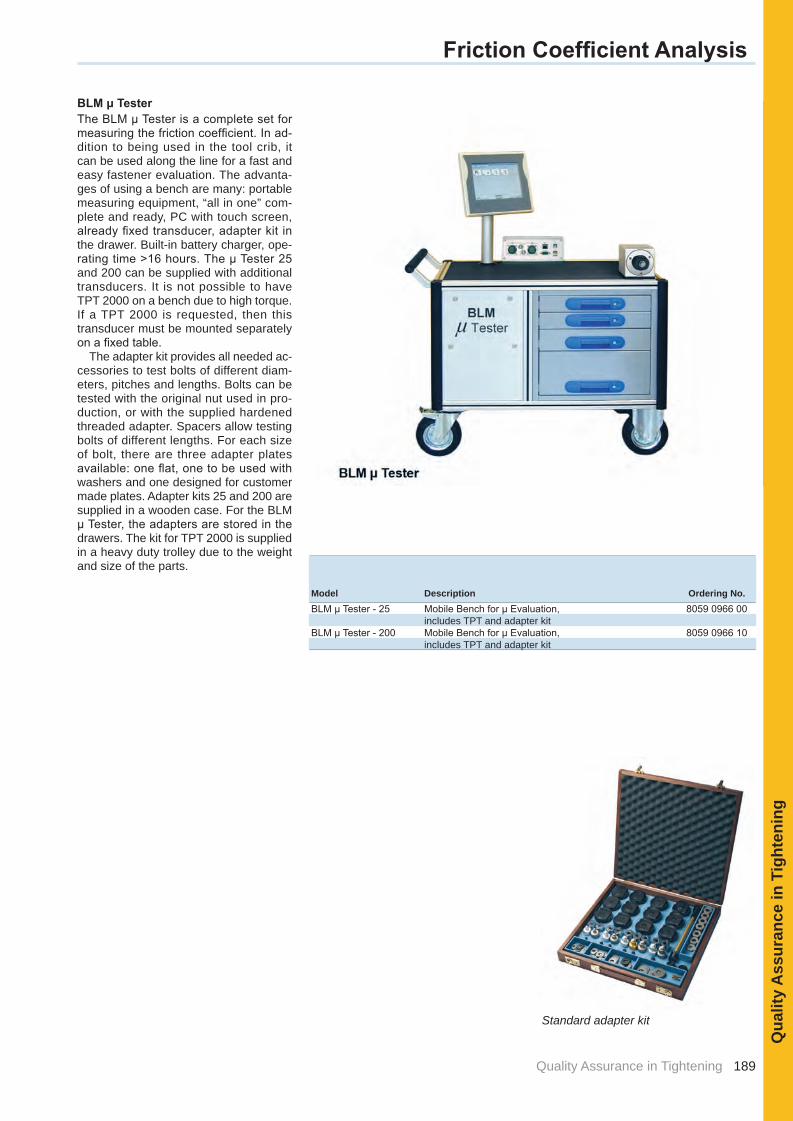
Qua
lity
Ass
uran
ce in
Tig
hten
ing
Quality Assurance in Tightening 189
Friction Coeffi cient Analysis
BLM μ TesterThe BLM μ Tester is a complete set for measuring the friction coeffi cient. In ad-dition to being used in the tool crib, it can be used along the line for a fast and easy fastener evaluation. The advanta-ges of using a bench are many: portable measuring equipment, “all in one” com-plete and ready, PC with touch screen, already fi xed transducer, adapter kit in the drawer. Built-in battery charger, ope-rating time >16 hours. The μ Tester 25 and 200 can be supplied with additional transducers. It is not possible to have TPT 2000 on a bench due to high torque. If a TPT 2000 is requested, then this transducer must be mounted separately on a fi xed table.
The adapter kit provides all needed ac-cessories to test bolts of different diam-eters, pitches and lengths. Bolts can be tested with the original nut used in pro-duction, or with the supplied hardened threaded adapter. Spacers allow testing bolts of different lengths. For each size of bolt, there are three adapter plates available: one fl at, one to be used with washers and one designed for customer made plates. Adapter kits 25 and 200 are supplied in a wooden case. For the BLM μ Tester, the adapters are stored in the drawers. The kit for TPT 2000 is supplied in a heavy duty trolley due to the weight and size of the parts.
Model Description Ordering No.BLM μ Tester - 25 Mobile Bench for μ Evaluation, 8059 0966 00 includes TPT and adapter kitBLM μ Tester - 200 Mobile Bench for μ Evaluation, 8059 0966 10 includes TPT and adapter kit
Standard adapter kit
Am_Qualityasstight.indd 189 2012-02-06 14:23:04
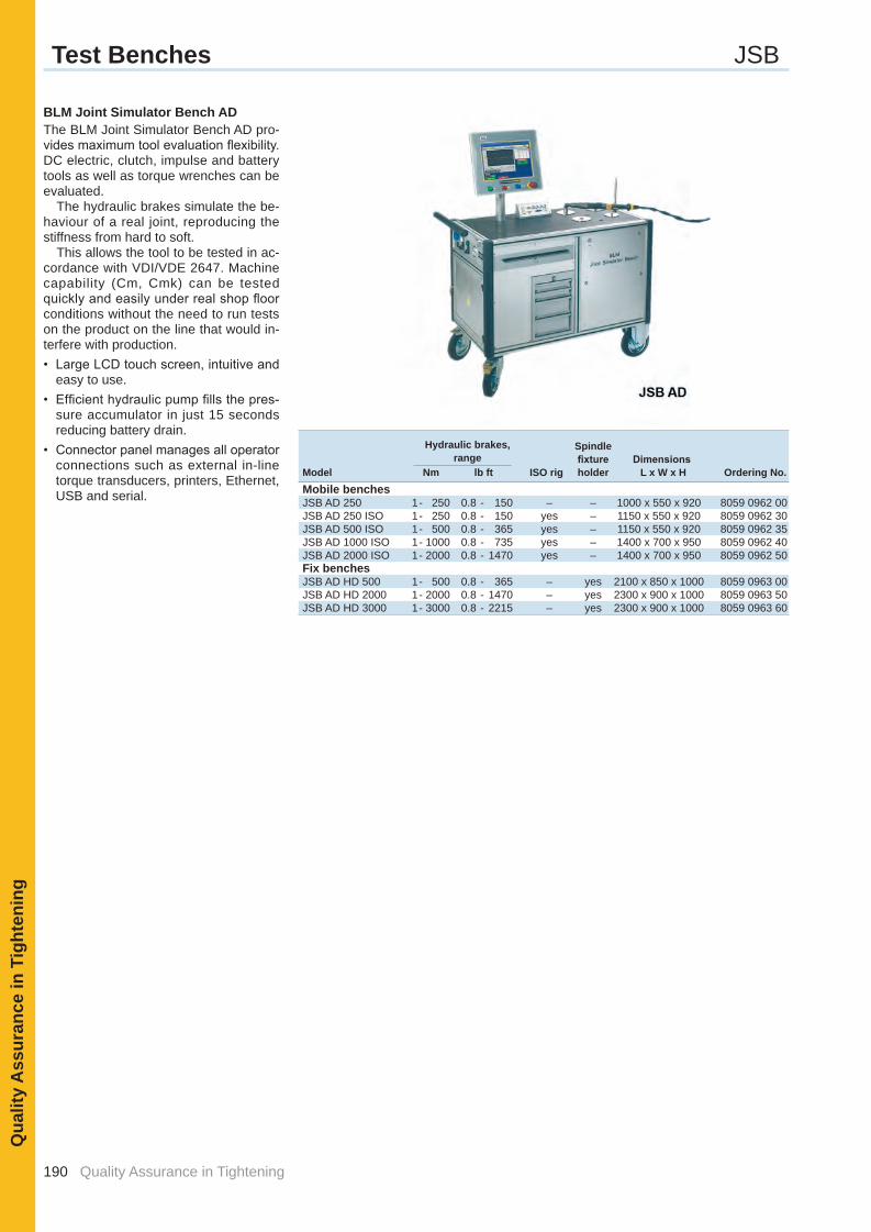
Q
ualit
y A
ssur
ance
in T
ight
enin
g
190 Quality Assurance in Tightening
Test Benches JSB
Hydraulic brakes, Spindle range fi xture Dimensions Model Nm lb ft ISO rig holder L x W x H Ordering No.Mobile benchesJSB AD 250 1 - 250 0.8 - 150 – – 1000 x 550 x 920 8059 0962 00JSB AD 250 ISO 1 - 250 0.8 - 150 yes – 1150 x 550 x 920 8059 0962 30JSB AD 500 ISO 1 - 500 0.8 - 365 yes – 1150 x 550 x 920 8059 0962 35JSB AD 1000 ISO 1 - 1000 0.8 - 735 yes – 1400 x 700 x 950 8059 0962 40JSB AD 2000 ISO 1 - 2000 0.8 - 1470 yes – 1400 x 700 x 950 8059 0962 50Fix benches JSB AD HD 500 1 - 500 0.8 - 365 – yes 2100 x 850 x 1000 8059 0963 00JSB AD HD 2000 1 - 2000 0.8 - 1470 – yes 2300 x 900 x 1000 8059 0963 50JSB AD HD 3000 1 - 3000 0.8 - 2215 – yes 2300 x 900 x 1000 8059 0963 60
BLM Joint Simulator Bench ADThe BLM Joint Simulator Bench AD pro-vides maximum tool evaluation fl exibility. DC electric, clutch, impulse and battery tools as well as torque wrenches can be evaluated.
The hydraulic brakes simulate the be-haviour of a real joint, reproducing the stiffness from hard to soft.
This allows the tool to be tested in ac-cordance with VDI/VDE 2647. Machine capability (Cm, Cmk) can be tested quickly and easily under real shop fl oor conditions without the need to run tests on the product on the line that would in-terfere with production.• Large LCD touch screen, intuitive and
easy to use.• Effi cient hydraulic pump fi lls the pres-
sure accumulator in just 15 seconds reducing battery drain.
• Connector panel manages all operator connections such as external in-line torque transducers, printers, Ethernet, USB and serial.
Am_Qualityasstight.indd 190 2012-02-06 14:23:04
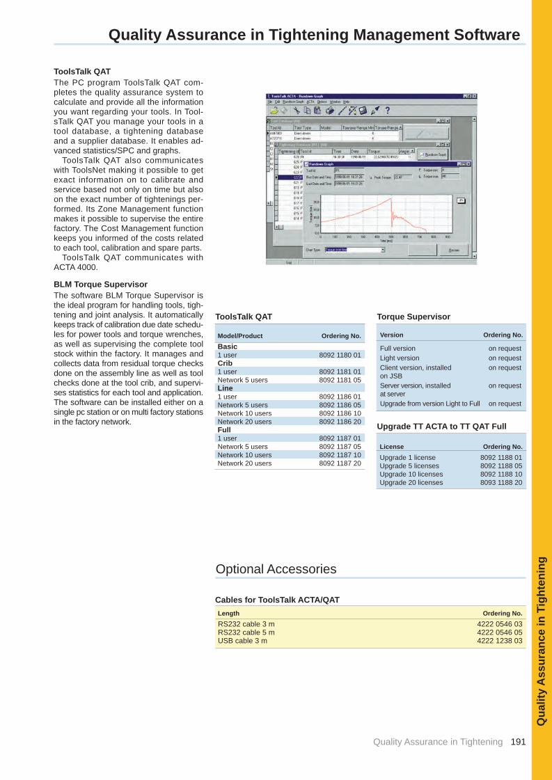
Qua
lity
Ass
uran
ce in
Tig
hten
ing
Quality Assurance in Tightening 191
Quality Assurance in Tightening Management Software
Version Ordering No.
Full version on requestLight version on requestClient version, installed on requeston JSBServer version, installed on requestat serverUpgrade from version Light to Full on request
Model/Product Ordering No.Basic 1 user 8092 1180 01Crib 1 user 8092 1181 01Network 5 users 8092 1181 05Line 1 user 8092 1186 01Network 5 users 8092 1186 05Network 10 users 8092 1186 10Network 20 users 8092 1186 20Full 1 user 8092 1187 01Network 5 users 8092 1187 05Network 10 users 8092 1187 10Network 20 users 8092 1187 20
ToolsTalk QAT Torque Supervisor
License Ordering No. Upgrade 1 license 8092 1188 01Upgrade 5 licenses 8092 1188 05Upgrade 10 licenses 8092 1188 10Upgrade 20 licenses 8093 1188 20
Upgrade TT ACTA to TT QAT Full
Cables for ToolsTalk ACTA/QATLength Ordering No.RS232 cable 3 m 4222 0546 03RS232 cable 5 m 4222 0546 05USB cable 3 m 4222 1238 03
Optional Accessories
ToolsTalk QATThe PC program ToolsTalk QAT com-pletes the quality assurance system to calculate and provide all the information you want regarding your tools. In Tool-sTalk QAT you manage your tools in a tool database, a tightening database and a supplier database. It enables ad-vanced statistics/SPC and graphs.
ToolsTalk QAT also communicates with ToolsNet making it possible to get exact information on to calibrate and service based not only on time but also on the exact number of tightenings per-formed. Its Zone Management function makes it possible to supervise the entire factory. The Cost Management function keeps you informed of the costs related to each tool, calibration and spare parts.
ToolsTalk QAT communicates with ACTA 4000.
BLM Torque SupervisorThe software BLM Torque Supervisor is the ideal program for handling tools, tigh-tening and joint analysis. It automatically keeps track of calibration due date schedu-les for power tools and torque wrenches, as well as supervising the complete tool stock within the factory. It manages and collects data from residual torque checks done on the assembly line as well as tool checks done at the tool crib, and supervi-ses statistics for each tool and application. The software can be installed either on a single pc station or on multi factory stations in the factory network.
Am_Qualityasstight.indd 191 2012-02-06 14:23:06

Grinders
Contents PageIntroduction ........................................... 193Product safety....................................... 194Selection guide ..................................... 195Turbine grinders and sanders ............... 196Die grinders .......................................... 198Straight grinders ................................... 200Angle grinders ...................................... 202Angle sanders....................................... 204Orbital and random orbital sanders ...... 206Dust extraction...................................... 208Routers ................................................. 211Nibblers ................................................ 211Circular cutters ..................................... 212
Am_Grinders.indd 192 2012-02-07 12:17:28
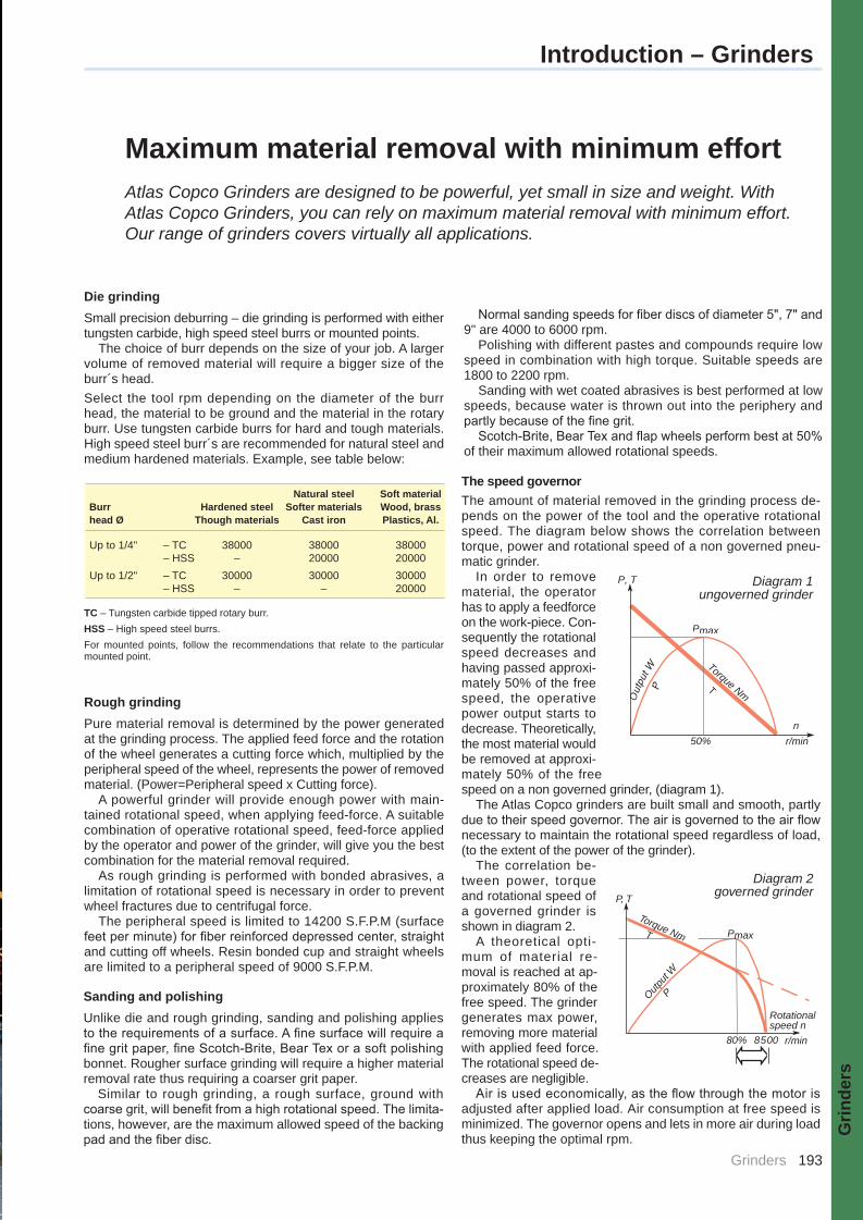
Grinders 193
Grin
ders
P, T
PmaxP
n
r/min50%
Torque NmT
O
Diagram 1ungoverned grinder
Die grind ingSmall precision deburring – die grinding is performed with either tungsten carbide, high speed steel burrs or mounted points.
The choice of burr depends on the size of your job. A larger volume of removed material will require a bigger size of the burr´s head.Select the tool rpm depending on the diameter of the burr head, the material to be ground and the material in the rotary burr. Use tungsten carbide burrs for hard and tough materials. High speed steel burr´s are recommended for natural steel and medium hardened materials. Example, see table below:
Introduction – Grinders
The speed governor The amount of material removed in the grinding process de-pends on the power of the tool and the operative rotational speed. The diagram below shows the correlation between torque, power and rotational speed of a non governed pneu-matic grinder.
In order to remove material, the operator has to apply a feedforce on the work-piece. Con-sequently the rotational speed decreases and having passed approxi-mately 50% of the free speed, the operative power output starts to decrease. Theoretically, the most material would be removed at approxi-mately 50% of the free speed on a non governed grinder, (diagram 1).
The Atlas Copco grinders are built small and smooth, partly due to their speed governor. The air is governed to the air fl ow necessary to maintain the rotational speed regardless of load, (to the extent of the power of the grinder).
The correlation be-tween power, torque and rotational speed of a governed grinder is shown in diagram 2.
A theoretical opti-mum of material re-moval is reached at ap-proximately 80% of the free speed. The grinder generates max power, removing more material with applied feed force. The rotational speed de-creases are negligible.
Air is used economically, as the fl ow through the motor is adjusted after applied load. Air consumption at free speed is minimized. The governor opens and lets in more air during load thus keeping the optimal rpm.
Sanding and polishingUnlike die and rough grinding, sanding and polishing applies to the requirements of a surface. A fi ne surface will require a fi ne grit paper, fi ne Scotch-Brite, Bear Tex or a soft polishing bonnet. Rougher surface grinding will require a higher material removal rate thus requiring a coarser grit paper.
Similar to rough grinding, a rough surface, ground with coarse grit, will benefi t from a high rotational speed. The limita-tions, however, are the maximum allowed speed of the backing pad and the fi ber disc.
Rough grindingPure material removal is determined by the power generated at the grinding process. The applied feed force and the rotation of the wheel generates a cutting force which, multiplied by the peripheral speed of the wheel, represents the power of removed material. (Power=Peripheral speed x Cutting force).
A powerful grinder will provide enough power with main-tained rotational speed, when applying feed-force. A suitable combination of operative rotational speed, feed-force applied by the operator and power of the grinder, will give you the best combination for the material removal required.
As rough grinding is performed with bonded abrasives, a limitation of rotational speed is necessary in order to prevent wheel fractures due to centrifugal force.
The peripheral speed is limited to 14200 S.F.P.M (surface feet per minute) for fi ber reinforced depressed center, straight and cutting off wheels. Resin bonded cup and straight wheels are limited to a peripheral speed of 9000 S.F.P.M.
Pmax
Rotationalspeed n
r/min80%
Torque NmT
8500
P, T
Outpu
t W
P
Diagram 2governed grinder
TC – Tungsten carbide tipped rotary burr.HSS – High speed steel burrs.For mounted points, follow the rec om men da tions that relate to the par tic u lar mount ed point.
Natural steel Soft materialBurr Hardened steel Softer materials Wood, brasshead Ø Though materials Cast iron Plastics, Al.
Up to 1/4" – TC 38000 38000 38000 – HSS – 20000 20000Up to 1/2" – TC 30000 30000 30000 – HSS – – 20000
Atlas Copco Grinders are designed to be powerful, yet small in size and weight. With Atlas Copco Grinders, you can rely on maximum material removal with minimum effort. Our range of grinders covers virtually all applications.
Maximum material removal with minimum effort
Normal sanding speeds for fi ber discs of diameter 5", 7" and 9" are 4000 to 6000 rpm.
Polishing with different pastes and compounds require low speed in combination with high torque. Suitable speeds are 1800 to 2200 rpm.
Sanding with wet coated abrasives is best performed at low speeds, because water is thrown out into the periphery and partly because of the fi ne grit.
Scotch-Brite, Bear Tex and fl ap wheels perform best at 50% of their maximum allowed rotational speeds.
Am_Grinders.indd 193 2012-02-07 12:17:31

194 Grinders
Grin
ders
Check that fl ange and wheel combinations correspond to national
regulations. Check that the fl anges are undamaged and that they are clean.
Wear– personal protection gog gles– ear pro tec tion– gloves (helmet in heav i er applications)
Test run your grinder in a protect-ed area after having assembled the wheelKeep the space around the grinding op er a tion free from other people.
MaintenanceMake sure to follow prescribed service instructions and intervals. Do not dis-assemble security parts, for example speed governor or overspeed shut-off. These parts have to be completely replaced when damaged.
This is your re spon si bil i tyThere are, how ev er, meas ures the op er a tor has to take in or der to avoid any risk of mis use or ac ci dent. The safe ty man u al, sup- plied with every grinder con tains a number of safe ty rules for the op er a tor. The 8 steps below are a basic sum ma ry of the safe ty manual. Remember to read the safe ty man u al as well.
Built-in safetyAt las Copco grind ers fea ture a high de gree of safe ty. Over-speed shut-off, safe ty throt tles and wheel guards are good ex- am ples of prod uct safe ty fea tures car ried by our grind ers.
Per form ance checkedEvery grinder leav ing our fac to ry is checked on maximum free speed and gen er al func tions.
Diameter – Peripheral speed – r/minThe table below will help you to translate the surface feet per minute of the grinding wheel to the right rotational speed of the grinder when using a specifi c diameter of grinding wheel.
Wheel Surface feet per minutediameterinches 4,000 4,500 5,000 5,500 6,000 6,500 7,000 7,500 8,000 8,500 9,000 9,500 10,000 12,000 12,000 14,200 Revolutions per minute1 15,279 17,189 19,099 21,008 22,918 24,828 26,737 28,647 30,558 32,467 34,377 36,287 38,197 45,837 47,746 54,2401 1/2 10,186 11,459 12,732 14,006 15,279 16,552 17,825 19,099 20,372 21,645 22,918 24,192 25,465 30,558 31,831 36,1602 7,639 8,594 9,549 10,504 11,459 12,414 13,369 14,324 15,279 16,234 17,189 18,144 19,099 22,918 23,873 27,120
2 1/2 6,112 6,875 7,639 8,403 9,167 9,931 10,695 11,459 12,223 12,987 13,751 14,515 15,279 18,335 19,099 21,6963 5,093 5,730 6,366 7,003 7,639 8,276 8,913 9,549 10,186 10,823 11,459 12,096 12,732 15,279 15,915 18,0803 1/2 4,365 4,911 5,457 6,002 6,548 7,094 7,639 8,185 8,731 9,276 9,822 10,368 10,913 13,096 13,642 15,497
4 3,820 4,297 4,775 5,252 5,730 6,207 6,685 7,162 7,640 8,117 8,594 9,072 9,549 11,459 11,937 13,5605 3,056 3,438 3,820 4,202 4,584 4,966 5,348 5,730 6,112 6,494 6,875 7,257 7,639 9,167 9,549 10,8486 2,546 2,865 3,183 3,501 3,820 4,138 4,465 4,775 5,093 5,411 5,730 6,048 6,366 7,639 7,958 9,040
7 2,183 2,456 2,728 3,001 3,274 3,547 3,820 4,093 4,365 4,638 4,911 5,148 5,457 6,548 6,821 7,7498 1,910 2,149 2,387 2,626 2,865 3,104 3,342 3,581 3,820 4,058 4,297 4,536 4,775 5,730 5,968 6,7809 1,699 1,910 2,122 2,334 2,546 2759 2,971 3,183 3,395 3,608 3,820 4,032 4,244 5,093 5,305 6,027
Product Safety
How to make it safer
Check the free speedThe measured speed at a pressure of 90 psi (6.3 bars) should not exceed the rated speed of the grinder. The wheel must be removed before the grinder is checked. The checks should be carried out regu-larly, especially after longer standstill. Make sure that the speed marking on the tool is legible.
Check the wheelguardAlways use the recommended wheel-guard and check that it is not dam- aged. Never use a grinder with out the wheelguard when the grind ing wheel re quires one.
Match the maximum speed of the wheel to the right grinderMake sure that the stated maximum speed of the grinder never ex ceeds the max i mum speed of the grinding wheel.
Check the grinding wheelMake sure that the grinding wheel is not cracked or damaged in any way. The grinding wheel should have the correct hole dimensions and should be fitted properly on the spindle to avoid unbal-anced vibrations or serious injury.
1
2
3
4
5
6
7
8
2 2
Am_Grinders.indd 194 2012-02-07 12:17:39
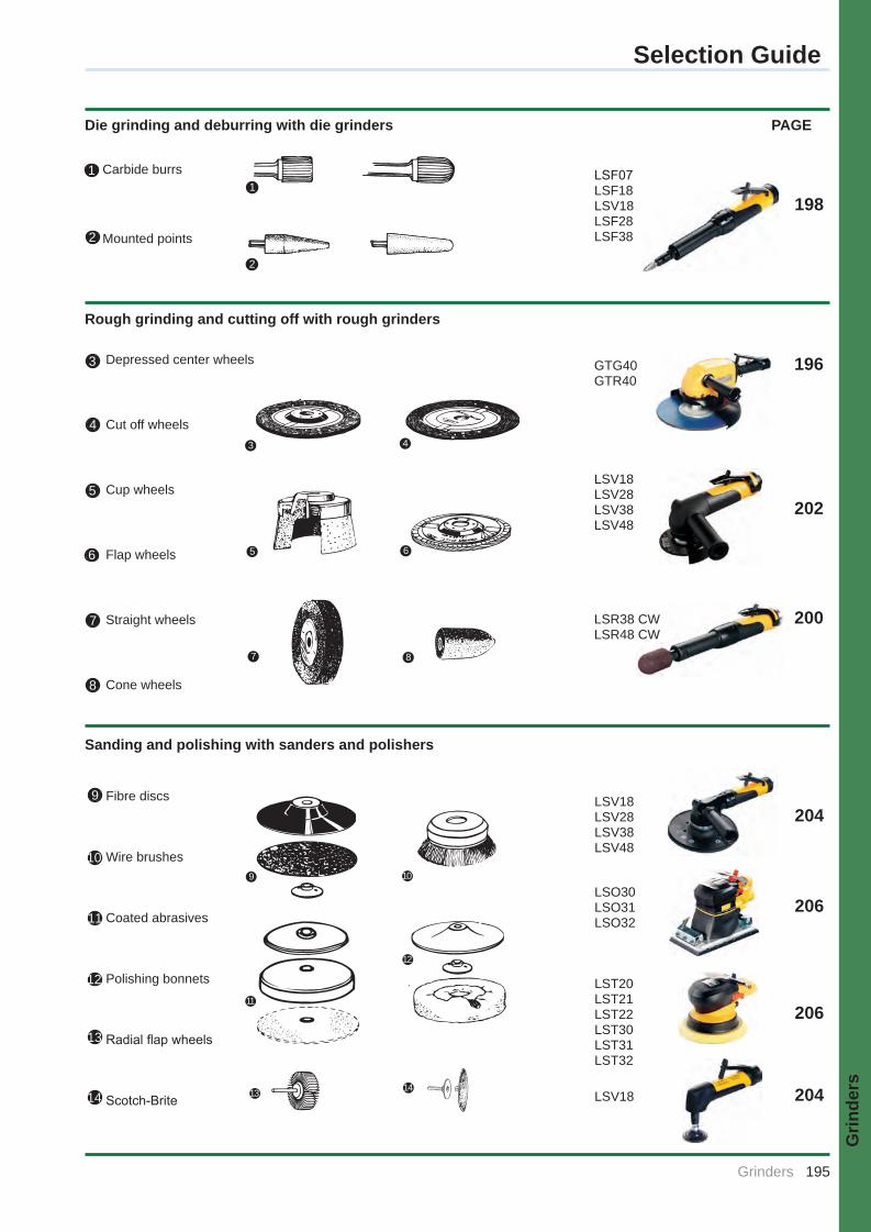
Grinders 195
87
65
3 4
2
1
1413
11
9 10
12
Grin
ders
Selection Guide
Die grinding and deburring with die grinders PAGE
Rough grinding and cutting off with rough grinders
Sanding and polishing with sanders and polishers
3
4
5
6
7
8
Depressed center wheels
Cut off wheels
Cup wheels
Flap wheels
Straight wheels
Cone wheels
9
10
11
14
13
12
Fibre discs
Wire brushes
Coated abrasives
Polishing bonnets
Radial fl ap wheels
Scotch-Brite
1
2
Carbide burrs
Mounted points
LSF07LSF18LSV18 198LSF28LSF38
GTG40 196GTR40
LSV18LSV28LSV38 202LSV48
LSR38 CW 200LSR48 CW
LSV18LSV28 204LSV38LSV48
LSO30LSO31 206LSO32
LST20LST21LST22 206LST30LST31LST32
LSV18 204
Am_Grinders.indd 195 2012-02-07 12:17:46
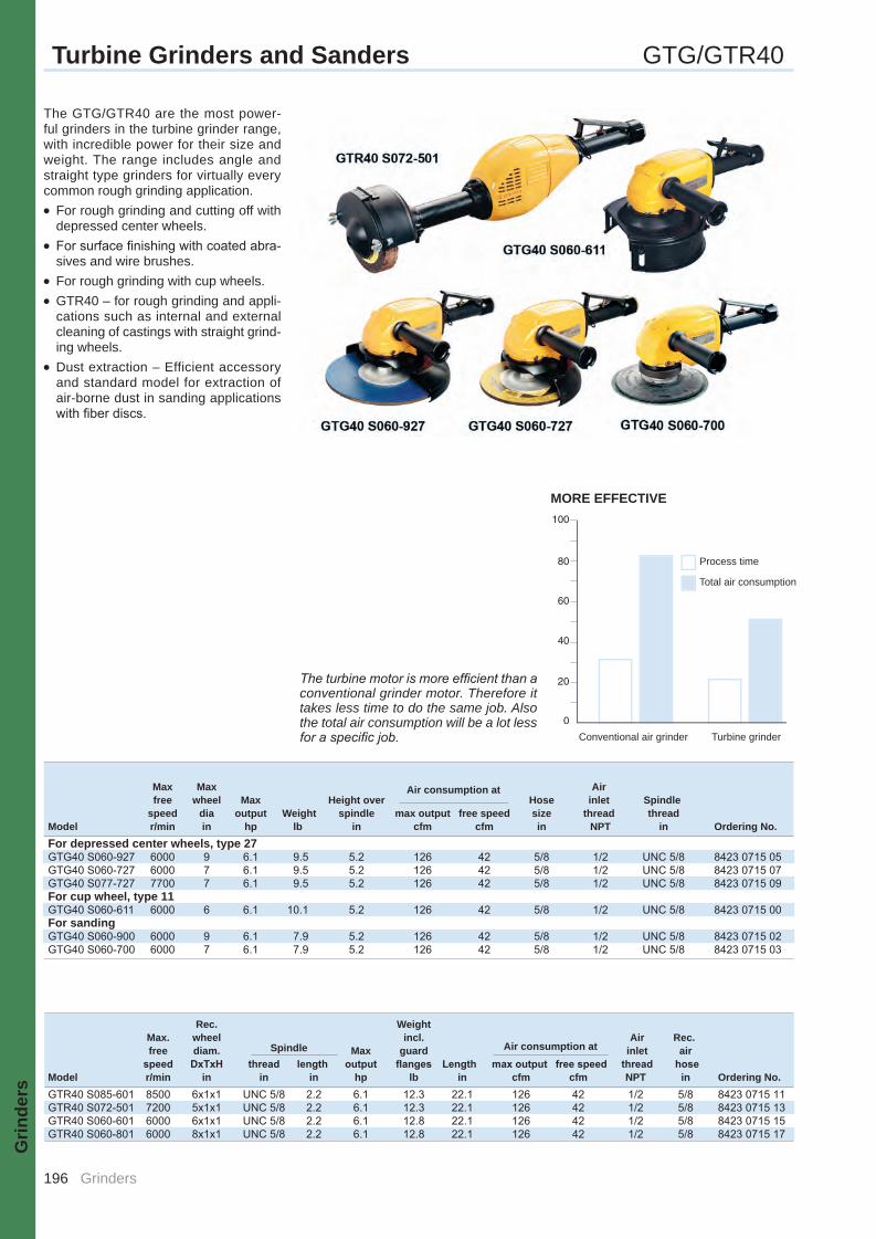
196 Grinders
Grin
ders
Max Max Air consumption at Air free wheel Max Height over Hose inlet Spindle speed dia output Weight spindle max output free speed size thread threadModel r/min in hp lb in cfm cfm in NPT in Ordering No.For depressed center wheels, type 27GTG40 S060-927 6000 9 6.1 9.5 5.2 126 42 5/8 1/2 UNC 5/8 8423 0715 05GTG40 S060-727 6000 7 6.1 9.5 5.2 126 42 5/8 1/2 UNC 5/8 8423 0715 07GTG40 S077-727 7700 7 6.1 9.5 5.2 126 42 5/8 1/2 UNC 5/8 8423 0715 09For cup wheel, type 11GTG40 S060-611 6000 6 6.1 10.1 5.2 126 42 5/8 1/2 UNC 5/8 8423 0715 00For sandingGTG40 S060-900 6000 9 6.1 7.9 5.2 126 42 5/8 1/2 UNC 5/8 8423 0715 02GTG40 S060-700 6000 7 6.1 7.9 5.2 126 42 5/8 1/2 UNC 5/8 8423 0715 03
Rec. Weight Max. wheel incl. Air Rec. free diam. Spindle Max guard Air consumption at inlet air speed DxTxH thread length output fl anges Length max output free speed thread hoseModel r/min in in in hp lb in cfm cfm NPT in Ordering No.GTR40 S085-601 8500 6x1x1 UNC 5/8 2.2 6.1 12.3 22.1 126 42 1/2 5/8 8423 0715 11GTR40 S072-501 7200 5x1x1 UNC 5/8 2.2 6.1 12.3 22.1 126 42 1/2 5/8 8423 0715 13GTR40 S060-601 6000 6x1x1 UNC 5/8 2.2 6.1 12.8 22.1 126 42 1/2 5/8 8423 0715 15GTR40 S060-801 6000 8x1x1 UNC 5/8 2.2 6.1 12.8 22.1 126 42 1/2 5/8 8423 0715 17
The GTG/GTR40 are the most power-ful grinders in the turbine grinder range, with incredible power for their size and weight. The range includes angle and straight type grinders for virtually every common rough grinding application.l For rough grinding and cutting off with
depressed center wheels.l For surface fi nishing with coated abra-
sives and wire brushes.l For rough grinding with cup wheels.l GTR40 – for rough grinding and appli-
cations such as internal and external cleaning of castings with straight grind-ing wheels.
l Dust extraction – Efficient accessory and standard model for extraction of air-borne dust in sanding applications with fi ber discs.
Process time
Total air consumption
The turbine motor is more effi cient than a conventional grinder motor. Therefore it takes less time to do the same job. Also the total air consumption will be a lot less for a specifi c job. Conventional air grinder Turbine grinder
MORE EFFECTIVE
Turbine Grinders and Sanders GTG/GTR40
Am_Grinders.indd 196 2012-02-07 12:17:47
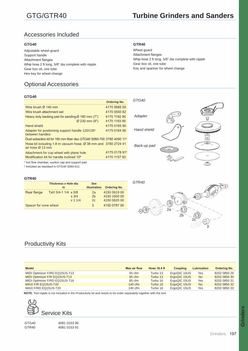
Grinders 197
2a2b
2c
3
Productivity KitsG
rinde
rs
GTG40Adjustable wheel guardSupport handleAttachment flanges Whip hose 2 ft long, 5/8" dia complete with nippleGear box oil, one tubeHex key for wheel change
GTG40
GTR40
GTR40Wheel guardAttachment flanges Whip hose 2 ft long, 5/8" dia complete with nippleGear box oil, one tubeKey and spanner for wheel change
GTR40 Thickness x Hole dia See in illustration Ordering No.
Rear flange TxH 3/4-1 1/4 x 5/8 2a 4150 0619 00 x 3/4 2b 4150 1650 00 x 1 1/4 2c 4150 0620 00Spacer for cone wheel 3 4150 0787 00
GTG40 4081 0153 90 GTR40 4081 0153 91
GTG40 Ordering No.
Wire brush Ø 140 mm 4170 0685 00Wire brush attachment set 4170 0550 82Heavy duty backing pad for sanding Ø 180 mm (7") 4170 1192 90 Ø 230 mm (9") 4170 1193 90Hand shield 4175 0165 90Adapter for positioning support handle 120/135o 4175 0164 90between handles Dust extraction kit for 180 mm fiber disc GTG40 S060-700 3780 4090 11a
Hose kit including 1.8 m vacuum hose, Ø 38 mm and 3780 2724 41air hose Ø 13 mm Attachment for cup wheel with plane hole 4175 0178 91b
Modification kit for handle inclined 10º 4170 1157 93a Incl flow chamber, suction cap and support pad.b Included as standard in GTG40 S060-611.
GTG/GTR40 Turbine Grinders and Sanders
Accessories Included
Service Kits
Optional Accessories
Adapter
Hand shield
Back-up pad
Model Max air flow Hose 16.4 ft Coupling Lubrication Ordering No.MIDI Optimizer F/RD EQ10US-T13 65 cfm Turbo 13 ErgoQIC 10US Yes 8202 0850 29MIDI Optimizer F/R EQ10US-T13 65 cfm Turbo 13 ErgoQIC 10US No 8202 0850 30MIDI Optimizer F/RD EQ15US-T16 85 cfm Turbo 16 ErgoQIC 15US Yes 8202 0850 31MAXI F/R EQ15US-T20 140 cfm Turbo 16 ErgoQIC 15US No 8202 0850 32MAXI F/RD EQ15US-T20 140 cfm Turbo 16 ErgoQIC 15US Yes 8202 0850 33
NOTE: Tool nipple is not included in the Productivity kit and needs to be order separately together with the tool.
Am_Grinders.indd 197 2012-02-07 12:17:48
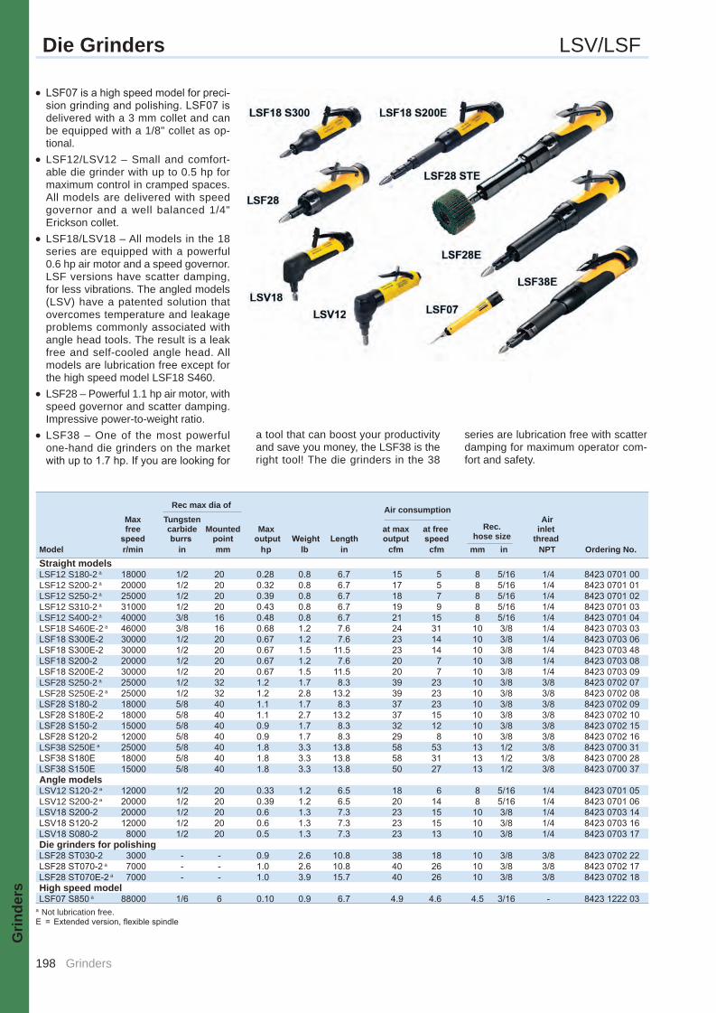
198 Grinders
Grin
ders
Rec max dia of Air consumption Max Tungsten Air free carbide Mounted Max at max at free Rec. inlet speed burrs point output Weight Length output speed hose size thread Model r/min in mm hp lb in cfm cfm mm in NPT Ordering No.Straight modelsLSF12 S180-2 a 18000 1/2 20 0.28 0.8 6.7 15 5 8 5/16 1/4 8423 0701 00LSF12 S200-2 a 20000 1/2 20 0.32 0.8 6.7 17 5 8 5/16 1/4 8423 0701 01LSF12 S250-2 a 25000 1/2 20 0.39 0.8 6.7 18 7 8 5/16 1/4 8423 0701 02LSF12 S310-2 a 31000 1/2 20 0.43 0.8 6.7 19 9 8 5/16 1/4 8423 0701 03LSF12 S400-2 a 40000 3/8 16 0.48 0.8 6.7 21 15 8 5/16 1/4 8423 0701 04 LSF18 S460E-2 a 46000 3/8 16 0.68 1.2 7.6 24 31 10 3/8 1/4 8423 0703 03LSF18 S300E-2 30000 1/2 20 0.67 1.2 7.6 23 14 10 3/8 1/4 8423 0703 06LSF18 S300E-2 30000 1/2 20 0.67 1.5 11.5 23 14 10 3/8 1/4 8423 0703 48LSF18 S200-2 20000 1/2 20 0.67 1.2 7.6 20 7 10 3/8 1/4 8423 0703 08LSF18 S200E-2 30000 1/2 20 0.67 1.5 11.5 20 7 10 3/8 1/4 8423 0703 09LSF28 S250-2 a 25000 1/2 32 1.2 1.7 8.3 39 23 10 3/8 3/8 8423 0702 07LSF28 S250E-2 a 25000 1/2 32 1.2 2.8 13.2 39 23 10 3/8 3/8 8423 0702 08LSF28 S180-2 18000 5/8 40 1.1 1.7 8.3 37 23 10 3/8 3/8 8423 0702 09LSF28 S180E-2 18000 5/8 40 1.1 2.7 13.2 37 15 10 3/8 3/8 8423 0702 10LSF28 S150-2 15000 5/8 40 0.9 1.7 8.3 32 12 10 3/8 3/8 8423 0702 15LSF28 S120-2 12000 5/8 40 0.9 1.7 8.3 29 8 10 3/8 3/8 8423 0702 16LSF38 S250E a 25000 5/8 40 1.8 3.3 13.8 58 53 13 1/2 3/8 8423 0700 31LSF38 S180E 18000 5/8 40 1.8 3.3 13.8 58 31 13 1/2 3/8 8423 0700 28LSF38 S150E 15000 5/8 40 1.8 3.3 13.8 50 27 13 1/2 3/8 8423 0700 37Angle modelsLSV12 S120-2 a 12000 1/2 20 0.33 1.2 6.5 18 6 8 5/16 1/4 8423 0701 05LSV12 S200-2 a 20000 1/2 20 0.39 1.2 6.5 20 14 8 5/16 1/4 8423 0701 06LSV18 S200-2 20000 1/2 20 0.6 1.3 7.3 23 15 10 3/8 1/4 8423 0703 14LSV18 S120-2 12000 1/2 20 0.6 1.3 7.3 23 15 10 3/8 1/4 8423 0703 16LSV18 S080-2 8000 1/2 20 0.5 1.3 7.3 23 13 10 3/8 1/4 8423 0703 17Die grinders for polishingLSF28 ST030-2 3000 - - 0.9 2.6 10.8 38 18 10 3/8 3/8 8423 0702 22LSF28 ST070-2 a 7000 - - 1.0 2.6 10.8 40 26 10 3/8 3/8 8423 0702 17LSF28 ST070E-2 a 7000 - - 1.0 3.9 15.7 40 26 10 3/8 3/8 8423 0702 18High speed modelLSF07 S850 a 88000 1/6 6 0.10 0.9 6.7 4.9 4.6 4.5 3/16 - 8423 1222 03
Die Grinders LSV/LSF
l LSF07 is a high speed model for preci-sion grinding and polishing. LSF07 is delivered with a 3 mm collet and can be equipped with a 1/8" collet as op-tional.
l LSF12/LSV12 – Small and comfort-able die grinder with up to 0.5 hp for maximum control in cramped spaces. All models are delivered with speed governor and a well balanced 1/4" Erickson collet.
l LSF18/LSV18 – All models in the 18 series are equipped with a powerful 0.6 hp air motor and a speed governor. LSF versions have scatter damping, for less vibrations. The angled models (LSV) have a patented solution that overcomes temperature and leakage problems commonly associated with angle head tools. The result is a leak free and self-cooled angle head. All models are lubrication free except for the high speed model LSF18 S460.
l LSF28 – Powerful 1.1 hp air motor, with speed governor and scatter damping. Impressive power-to-weight ratio.
l LSF38 – One of the most powerful one-hand die grinders on the market with up to 1.7 hp. If you are looking for
a Not lubrication free.E = Extended version, fl exible spindle
a tool that can boost your productivity and save you money, the LSF38 is the right tool! The die grinders in the 38
series are lubrication free with scatter damping for maximum operator com-fort and safety.
Am_Grinders.indd 198 2012-02-07 12:17:49
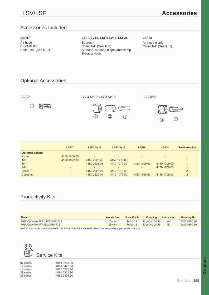
Grinders 199
LSF07 LSF28/38LSF/LSV12, LSF/LSV18
Grin
ders
Productivity Kits
LSV/LSF Accessories
Accessories Included
Service Kits07 series 4081 0243 9012 series 4081 0472 9018 series 4081 0355 9028 series 4081 0315 9038 series 4081 0308 90
Optional Accessories
LSF38Air hose nippleCollet 1/4" (See ill. 1)
LSF/LSV12, LSF/LSV18, LSF28SpannerCollet 1/4" (See ill. 1)Air hose, air hose nipple and clampExhaust hose
LSF07Air hoseErgoNIP 08Collet 1/8" (See ill. 1)
LSF07 LSF/LSV12 LSF/LSV18 LSF28 LSF38 See illustration
Optional collets3 mm 4150 1800 00 - - - - 11/8" 4150 1822 00 4150 2226 46 4150 1710 00 - - 11/4" - 4150 2226 03 4112 1077 00 4150 1709 00 4150 1709 00 13/8" - - - - 4150 1708 00 1Collar - 4150 2226 02 4112 1078 00 - - 2Collet nut - 4150 2226 04 4112 1076 00 4150 1706 00 4150 1706 00 3
j
kl jl j
Model Max air flow Hose 16.4 ft Coupling Lubrication Ordering No.MIDI Optimizer F/RD EQ10US-T13 65 cfm Turbo 13 ErgoQIC 10US Yes 8202 0850 29MIDI Optimizer F/R EQ10US-T13 65 cfm Turbo 13 ErgoQIC 10US No 8202 0850 30NOTE: Tool nipple is not included in the Productivity kit and needs to be order separately together with the tool.
Am_Grinders.indd 199 2012-02-07 12:17:50
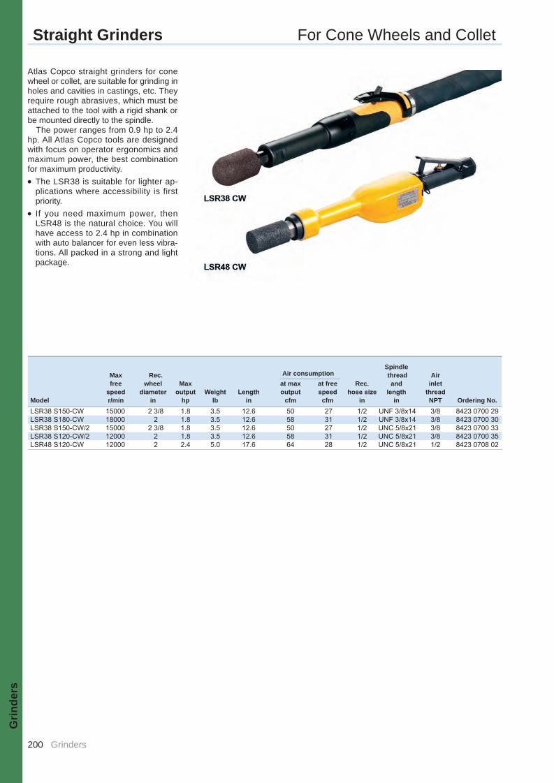
200 Grinders
Grin
ders
Straight Grinders For Cone Wheels and Collet
Atlas Copco straight grinders for cone wheel or collet, are suitable for grinding in holes and cavities in castings, etc. They require rough abrasives, which must be attached to the tool with a rigid shank or be mounted directly to the spindle.
The power ranges from 0.9 hp to 2.4 hp. All Atlas Copco tools are designed with focus on operator ergonomics and maximum power, the best combination for maximum productivity.l The LSR38 is suitable for lighter ap-
plications where accessibility is first priority.
l If you need maximum power, then LSR48 is the natural choice. You will have access to 2.4 hp in combination with auto balancer for even less vibra-tions. All packed in a strong and light package.
Spindle Max Rec. Air consumption thread Air free wheel Max at max at free Rec. and inlet speed diameter output Weight Length output speed hose size length threadModel r/min in hp lb in cfm cfm in in NPT Ordering No.LSR38 S150-CW 15000 2 3/8 1.8 3.5 12.6 50 27 1/2 UNF 3/8x14 3/8 8423 0700 29LSR38 S180-CW 18000 2 1.8 3.5 12.6 58 31 1/2 UNF 3/8x14 3/8 8423 0700 30LSR38 S150-CW/2 15000 2 3/8 1.8 3.5 12.6 50 27 1/2 UNC 5/8x21 3/8 8423 0700 33LSR38 S120-CW/2 12000 2 1.8 3.5 12.6 58 31 1/2 UNC 5/8x21 3/8 8423 0700 35LSR48 S120-CW 12000 2 2.4 5.0 17.6 64 28 1/2 UNC 5/8x21 1/2 8423 0708 02
Am_Grinders.indd 200 2012-02-07 12:17:51

Grinders 201
LSR48-CW
LSR38-CW
Grin
ders
Productivity Kits
For Cone Wheels and Collet Accessories
Accessories Included
Optional Accessories
28 series 4081 0315 9038 series 4081 0311 9048 series 4081 2023 90
LSR48 CWWhip hoseWrenchCone wheel adapter UNC 5/8"-11, (See ill. 2)
Service Kits
LSR48 See illustration Ordering No.
Adapter for cone wheel with threadUNC/W 5/8" 2 4150 0945 01
See illustration Ordering No.
Adapter for cone wheel with threadUNC/W 3/8" 1 4150 0318 00UNF 3/8" 1 4150 0318 01UNC 1/2" 1 4150 1357 00UNC/W 5/8" 1 4150 0767 00
LSR38
k
j
Model Max air fl ow Hose 16.4 ft Coupling Lubrication Ordering No.MIDI Optimizer F/RD EQ10US-T13 65 cfm Turbo 13 ErgoQIC 10US Yes 8202 0850 29MIDI Optimizer F/R EQ10US-T13 65 cfm Turbo 13 ErgoQIC 10US No 8202 0850 30
NOTE: Tool nipple is not included in the Productivity kit and needs to be order separately together with the tool.
LSR38 CWExhaust air hose (1.1 ft)Hose clamp Open end spannerFor -CW: UNF 3/8" (See ill. 1)For -CW/2: UNC/W 5/8" (See ill. 1)
Am_Grinders.indd 201 2012-02-07 12:17:51

202 Grinders
Angle Grinders For Depressed Center and Cut-off WheelsG
rinde
rs
No matter which of our vane grinders you choose you will get durable tools with high power and low weight. In addition, vibrations and noise are on a low level.l LSV18 – For work in cramped spaces,
the LSV 18 series is small yet power-ful, and lubrication free.
Features: Speed governor, sealed an-glehead, thermally insulated handle and lubrication-free air motor.
l LSV28 – Small, yet powerful giving 1 hp. Available in an extended version for optimal accessibility.
Features: Speed governor and ther-mally insulated handle.
l LSV38 – If you are looking for the most powerful one-hand grinder on the mar-ket, then you have found it – up to 1.7 hp.
Features: Speed governor, sealed angle head, lubrication-free air motor, thermally insulated handle, spindle lock and adjustable wheel guard.
l LSV48 – Our most powerful angle vane grinder with 2.5 hp for ultimate productivity.
Features: Speed governor, sealed angle head, lubrication-free air motor, thermally insulated handle and spindle lock. The autobalancer reduces the vi-brations by up to 50%.
Max Max Height Air consumption Spindle Air free wheel Max over at max at free thread and Hose inlet speed dia output Weight spindle output speed length size threadModel r/min in hp lb in cfm cfm in in NPT Ordering No.LSV18 S170-327 17000 3 0.6 1.6 2.8 23 14 UNF 3/8x17 3/8 1/4 8423 0705 51LSV28 ST13-427E 13000 4 1.0 3.7 3.1 37 16 UNF 3/8x17 3/8 3/8 8423 0706 00LSV28 ST12-427 12000 4 1.0 3.7 3.2 37 16 UNF 3/8x18 3/8 3/8 8423 0706 01LSV38 ST12-427 12000 4 1.7 3.5 3.3 58 31 UNF 3/8x17 3/8 1/2 8423 0700 20LSV38 ST12-527 12000 4 1/2-5 1.7 4.0 3.3 58 31 UNC 5/8x20 3/8 1/2 8423 0700 22LSV38 S12-427 12000 4 1.7 4.0 3.3 58 31 UNF 3/8x17 3/8 1/2 8423 0700 23LSV48 SA120-527 12000 5 2.5 5.5 3.9 76 36 UNC 5/8x21 5/8 1/2 8423 0707 53LSV48 SA085-727 8500 7 2.5 6.2 3.9 76 36 UNC 5/8x21 5/8 1/2 8423 0707 52LSV48 SA066-727 6600 7 2.5 5.1 3.9 76 36 UNC 5/8x21 5/8 1/2 8423 0707 54
Selection Guide
With wheel guard for disc -327 = Ø 3" -427 = Ø 4" -527 = Ø 5" and 4.5" -727 = Ø 7"
LSV38 S12-427 LSV38 ST12-427 LSV38 ST12-5271.7 hp air motor x x xAdjustable guard positions x x xLockable spindle x xSide handle x xSize wheel, inch 4 4 4.5 and 5Spindle thread, inch UNF 3/8 UNF 3/8 UNC 5/8
How to choose your LSV38
Am_Grinders.indd 202 2012-02-07 12:17:52
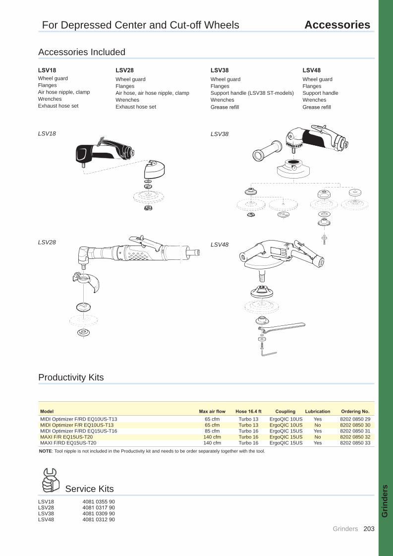
Grinders 203
Productivity Kits
For Depressed Center and Cut-off Wheels Accessories
Grin
ders
LSV18 Wheel guardFlangesAir hose nipple, clampWrenchesExhaust hose set
Service KitsLSV18 4081 0355 90LSV28 4081 0317 90LSV38 4081 0309 90LSV48 4081 0312 90
Accessories Included
LSV28Wheel guardFlanges Air hose, air hose nipple, clampWrenchesExhaust hose set
LSV38Wheel guardFlangesSupport handle (LSV38 ST-models)WrenchesGrease refill
LSV48Wheel guardFlangesSupport handleWrenchesGrease refill
LSV18
LSV28
LSV38
LSV48
Model Max air flow Hose 16.4 ft Coupling Lubrication Ordering No.MIDI Optimizer F/RD EQ10US-T13 65 cfm Turbo 13 ErgoQIC 10US Yes 8202 0850 29MIDI Optimizer F/R EQ10US-T13 65 cfm Turbo 13 ErgoQIC 10US No 8202 0850 30MIDI Optimizer F/RD EQ15US-T16 85 cfm Turbo 16 ErgoQIC 15US Yes 8202 0850 31MAXI F/R EQ15US-T20 140 cfm Turbo 16 ErgoQIC 15US No 8202 0850 32MAXI F/RD EQ15US-T20 140 cfm Turbo 16 ErgoQIC 15US Yes 8202 0850 33NOTE: Tool nipple is not included in the Productivity kit and needs to be order separately together with the tool.
Am_Grinders.indd 203 2012-02-07 12:17:54
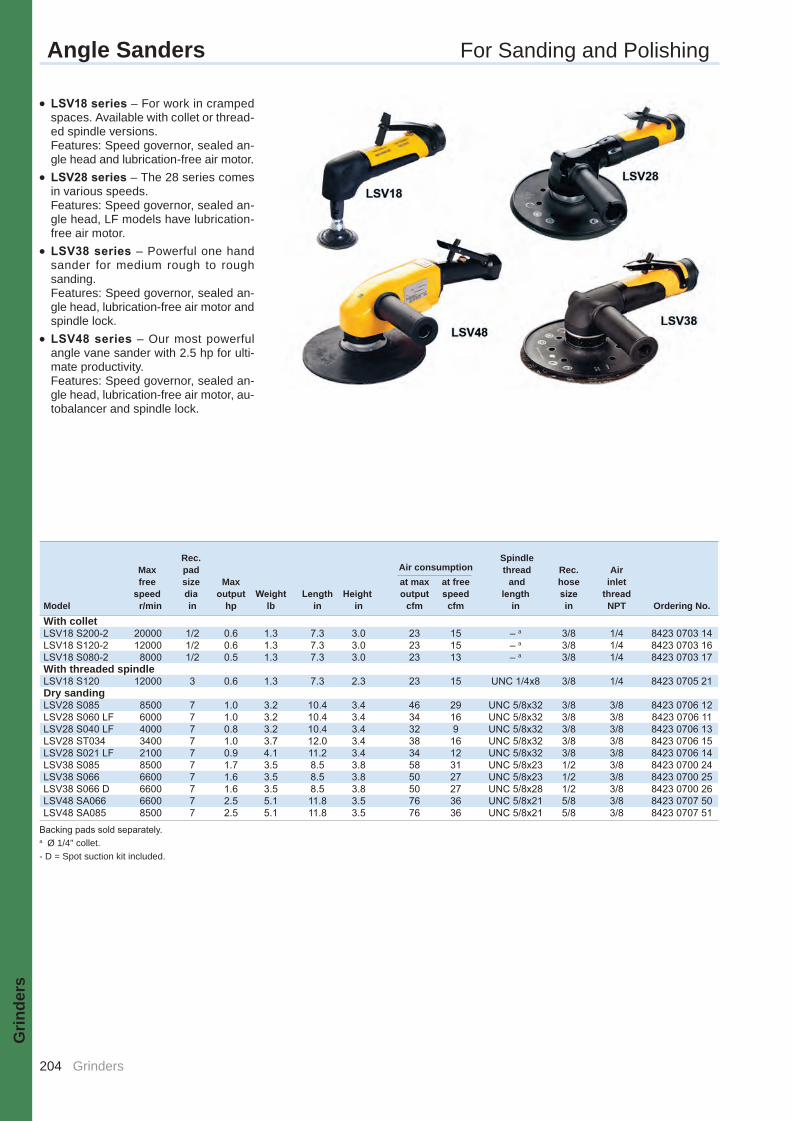
204 Grinders
Grin
ders
Rec. Spindle Max pad Air consumption thread Rec. Air free size Max at max at free and hose inlet speed dia output Weight Length Height output speed length size thread Model r/min in hp lb in in cfm cfm in in NPT Ordering No.With colletLSV18 S200-2 20000 1/2 0.6 1.3 7.3 3.0 23 15 – a 3/8 1/4 8423 0703 14LSV18 S120-2 12000 1/2 0.6 1.3 7.3 3.0 23 15 – a 3/8 1/4 8423 0703 16LSV18 S080-2 8000 1/2 0.5 1.3 7.3 3.0 23 13 – a 3/8 1/4 8423 0703 17With threaded spindleLSV18 S120 12000 3 0.6 1.3 7.3 2.3 23 15 UNC 1/4x8 3/8 1/4 8423 0705 21Dry sandingLSV28 S085 8500 7 1.0 3.2 10.4 3.4 46 29 UNC 5/8x32 3/8 3/8 8423 0706 12LSV28 S060 LF 6000 7 1.0 3.2 10.4 3.4 34 16 UNC 5/8x32 3/8 3/8 8423 0706 11LSV28 S040 LF 4000 7 0.8 3.2 10.4 3.4 32 9 UNC 5/8x32 3/8 3/8 8423 0706 13LSV28 ST034 3400 7 1.0 3.7 12.0 3.4 38 16 UNC 5/8x32 3/8 3/8 8423 0706 15LSV28 S021 LF 2100 7 0.9 4.1 11.2 3.4 34 12 UNC 5/8x32 3/8 3/8 8423 0706 14LSV38 S085 8500 7 1.7 3.5 8.5 3.8 58 31 UNC 5/8x23 1/2 3/8 8423 0700 24LSV38 S066 6600 7 1.6 3.5 8.5 3.8 50 27 UNC 5/8x23 1/2 3/8 8423 0700 25LSV38 S066 D 6600 7 1.6 3.5 8.5 3.8 50 27 UNC 5/8x28 1/2 3/8 8423 0700 26LSV48 SA066 6600 7 2.5 5.1 11.8 3.5 76 36 UNC 5/8x21 5/8 3/8 8423 0707 50LSV48 SA085 8500 7 2.5 5.1 11.8 3.5 76 36 UNC 5/8x21 5/8 3/8 8423 0707 51
Angle Sanders For Sanding and Polishing
Backing pads sold separately.a Ø 1/4" collet.- D = Spot suction kit included.
l LSV18 series – For work in cramped spaces. Available with collet or thread-ed spindle versions.
Features: Speed governor, sealed an-gle head and lubrication-free air motor.
l LSV28 series – The 28 series comes in various speeds.
Features: Speed governor, sealed an-gle head, LF models have lubrication-free air motor.
l LSV38 series – Powerful one hand sander for medium rough to rough sanding.
Features: Speed governor, sealed an-gle head, lubrication-free air motor and spindle lock.
l LSV48 series – Our most powerful angle vane sander with 2.5 hp for ulti-mate productivity.
Features: Speed governor, sealed an-gle head, lubrication-free air motor, au-tobalancer and spindle lock.
Am_Grinders.indd 204 2012-02-07 12:17:54
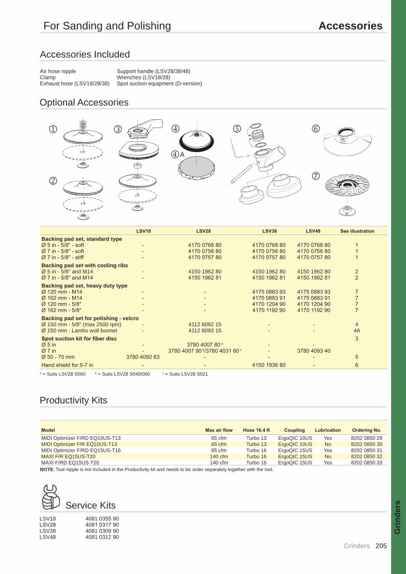
Grinders 205
4009150
mA
Grin
ders
Accessories Included
Optional Accessories
Service KitsLSV18 4081 0355 90LSV28 4081 0317 90LSV38 4081 0309 90LSV48 4081 0312 90
o
p
j
k
For Sanding and Polishing Accessories
l m n
LSV18 LSV28 LSV38 LSV48 See illustration Backing pad set, standard typeØ 5 in - 5/8" - soft - 4170 0768 80 4170 0768 80 4170 0768 80 1Ø 7 in - 5/8" - soft - 4170 0756 80 4170 0756 80 4170 0756 80 1Ø 7 in - 5/8" - stiff - 4170 0757 80 4170 0757 80 4170 0757 80 1Backing pad set with cooling ribs Ø 5 in - 5/8" and M14 - 4150 1962 80 4150 1962 80 4150 1962 80 2Ø 7 in - 5/8" and M14 - 4150 1962 81 4150 1962 81 4150 1962 81 2Backing pad set, heavy duty type Ø 120 mm - M14 - - 4175 0883 93 4175 0883 93 7Ø 162 mm - M14 - - 4175 0883 91 4175 0883 91 7Ø 120 mm - 5/8" - - 4170 1204 90 4170 1204 90 7Ø 162 mm - 5/8" - - 4170 1192 90 4170 1192 90 7Backing pad set for polishing - velcro Ø 150 mm - 5/8" (max 2500 rpm) - 4112 6092 15 - - 4Ø 150 mm - Lambs woll bonnet - 4112 6093 15 - - 4ASpot suction kit for fi ber disc 3Ø 5 in - 3780 4007 80 a - - Ø 7 in - 3780 4007 90 b/3780 4031 60 c - 3780 4093 40 Ø 50 - 75 mm 3780 4092 63 - - - 5Hand shield for 5-7 in - - 4150 1936 80 - 6
a = Suits LSV28 S060 b = Suits LSV28 S040/060 c = Suits LSV28 S021
Air hose nippleClampExhaust hose (LSV18/28/38)
Support handle (LSV28/38/48)Wrenches (LSV18/28)Spot suction equipment (D-version)
Productivity Kits
Model Max air fl ow Hose 16.4 ft Coupling Lubrication Ordering No.MIDI Optimizer F/RD EQ10US-T13 65 cfm Turbo 13 ErgoQIC 10US Yes 8202 0850 29MIDI Optimizer F/R EQ10US-T13 65 cfm Turbo 13 ErgoQIC 10US No 8202 0850 30MIDI Optimizer F/RD EQ15US-T16 85 cfm Turbo 16 ErgoQIC 15US Yes 8202 0850 31MAXI F/R EQ15US-T20 140 cfm Turbo 16 ErgoQIC 15US No 8202 0850 32MAXI F/RD EQ15US-T20 140 cfm Turbo 16 ErgoQIC 15US Yes 8202 0850 33NOTE: Tool nipple is not included in the Productivity kit and needs to be order separately together with the tool.
Am_Grinders.indd 205 2012-02-07 12:17:56
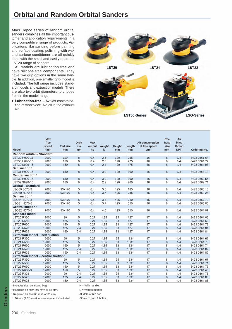
206 Grinders
Grin
ders
Max Rec. Air free Orbit Max Air consumption hose inlet speed Pad size dia output Weight Height Length at free speed size thread Model r/min mm mm hp lb mm mm cfm mm NPT Ordering No.Random orbital – StandardLST30 H090-11 9000 110 8 0.4 2.6 120 255 16 8 1/4 8423 0361 64LST30 H090-15 9000 150 8 0.4 2.6 120 275 16 8 1/4 8423 0361 72LST30 S090-15 9000 150 8 0.4 2.4 120 175 16 8 1/4 8423 0361 98Self suction a
LST31 H090-15 9000 150 8 0.4 3.0 120 300 16 8 1/4 8423 0363 19Central suction b
LST32 H090-15 9000 150 8 0.4 3.0 120 300 16 8 1/4 8423 0362 55LST32 S090-15 9000 150 8 0.4 2.9 120 200 16 8 1/4 8423 0362 71Orbital – StandardLSO30 S070-3 7000 93x170 5 0.4 3.5 125 185 16 8 1/4 8423 0360 16LSO30 H070-3 7000 93x170 5 0.4 3.7 125 285 16 8 1/4 8423 0360 24Self suction a
LSO31 S070-3 7000 93x170 5 0.4 3.5 125 210 16 8 1/4 8423 0362 79LSO31 H070-3 7000 93x170 5 0.4 3.7 125 310 16 8 1/4 8423 0363 03Central suction c
LSO32 H070-3 7000 93x170 5 0.4 4.0 125 310 16 8 1/4 8423 0361 07Standard modelLST20 R350 12000 90 5 0.27 1.85 95 127 17 8 1/4 8423 0361 65LST20 R550 12000 125 5 0.27 1.85 83 127 17 8 1/4 8423 0361 69LST20 R650 12000 150 5 0.27 1.85 83 127 17 8 1/4 8423 0361 73LST20 R525 12000 125 2.4 0.27 1.85 83 127 17 8 1/4 8423 0361 81LST20 R625 12000 150 2.4 0.27 1.85 83 127 17 8 1/4 8423 0361 84Extraction model – self suctionLST21 R350 12000 90 5 0.27 1.85 95 133 d 17 8 1/4 8423 0361 66LST21 R550 12000 125 5 0.27 1.85 83 133 d 17 8 1/4 8423 0361 70LST21 R650 12000 150 5 0.27 1.85 83 133 d 17 8 1/4 8423 0361 74LST21 R525 12000 125 2.4 0.27 1.85 83 133 d 17 8 1/4 8423 0361 82LST21 R625 12000 150 2.4 0.27 1.85 83 133 d 17 8 1/4 8423 0361 85Extraction model – central suction c
LST22 R350 12000 90 5 0.27 1.85 95 133 d 17 8 1/4 8423 0361 67LST22 R550 12000 125 5 0.27 1.85 83 133 d 17 8 1/4 8423 0361 71LST22 R650 12000 150 5 0.27 1.85 83 133 d 17 8 1/4 8423 0361 75LST22 R650-9 12000 150 5 0.27 1.85 83 133 d 17 8 1/4 8423 0361 40LST22 R325 12000 90 2.4 0.27 1.85 95 133 d 17 8 1/4 8423 0361 78LST22 R525 12000 125 2.4 0.27 1.85 83 133 d 17 8 1/4 8423 0361 83LST22 R625 12000 150 2.4 0.27 1.85 83 133 d 17 8 1/4 8423 0361 86
H = With handle.S = Without handle.All data at 6.3 bar.-9 Velcro pad, 9 holes.
a Includes dust collecting bag.b Required air fl ow 150 m3/h or 88 cfm.c Required air fl ow 60 m3/h or 35 cfm.d 186 mm (7.3") suction hose connector included.
Orbital and Random Orbital Sanders
Atlas Copco series of random orbital sanders combines all the important cus-tomer and application requirements in a very competitive range of products. Ap-plications like sanding before painting and surface coating, polishing with wax and surface conditioner are all quickly done with the small and easily operated LST20-range of sanders.
All models are lubrication free and have silicone free components. They have two grip options in the same han-dle. In addition, one smaller grip model is included. The full range includes stand-ard models and extraction models. There are also two orbit diameters to choose from in the model range.l Lubrication-free – Avoids con tam i na-
tion of workpiece. No oil in the ex haust air.
Am_Grinders.indd 206 2012-02-07 12:17:57
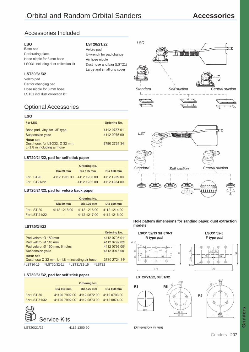
Grinders 207
3434 22 22
55 55
170
93
Ø 10
Ø 10
172
3030 47 47
68 68
93
LST
Ø85
Ø 120 Ø146
Ø 71Ø80
60˚Ø12
72˚Ø 12
R3 R5
R6
LSO
Dimension in mm Grin
ders
Orbital and Random Orbital Sanders Accessories
Standard Self suction Central suction
Standard Central suction
LS031/32/33 S/H070-3 LSO31/32-3 R-type pad F-type pad
Self suction
LST20/21/22, 30/31/32
Accessories Included
Optional Accessories
LSOBase padPerforating plateHose nipple for 8 mm hoseLSO31 including dust collection kit
Service KitsLST20/21/22 4112 1300 90
Hole pattern dimensions for sanding paper, dust extraction models
LSOFor LSO Ordering No.
Base pad, vinyl for -3F-type 4112 0787 01Suspension yoke 4112 0975 00Hose setDust hose, for LSO32, Ø 32 mm, 3780 2724 34L=1.8 m including air hose
LST20/21/22, pad for self stick paper
Ordering No.
Dia 89 mm Dia 125 mm Dia 150 mm
For LST20 4112 1231 00 4112 1233 00 4112 1235 00For LST21/22 4112 1232 00 4112 1234 00
LST30/31/32 Ordering No.
Pad velcro, Ø 150 mm 4112 0795 01a
Pad velcro, Ø 110 mm 4112 0792 02b
Pad velcro, Ø 150 mm, 6 holes 4112 0796 00c
Suspension yoke 4112 0975 00Hose set Dust hose Ø 32 mm, L=1.8 m including air hose 3780 2724 34d
LST20/21/22Velcro padU-wrench for pad changeAir hose nippleDust hose and bag (LST21)Large and small grip cover
LST30/31/32Velcro padBar for changing padHose nipple for 8 mm hoseLST31 incl dust collection kit
LST30/31/32, pad for self stick paper
Ordering No.
Dia 110 mm Dia 125 mm Dia 150 mm
For LST 30 41120 7992 00 4112 0872 00 4112 0793 00For LST 31/32 41120 7992 00 4112 0873 00 4112 0874 00
LST20/21/22, pad for velcro back paper
Ordering No.
Dia 89 mm Dia 125 mm Dia 150 mm
For LST 20 4112 1218 00 4112 1216 00 4112 1214 00For LST 21/22 - 4112 1217 00 4112 1215 00
a LST30-15 b LST30/32-11 c LST31/32-15 d LST32
Am_Grinders.indd 207 2012-02-07 12:17:58

208 Grinders
Grin
ders
Dust Extraction
The fact that dust can represent a haz-ard in the working environment is well documented.
Dust particles from certain materials are dangerous to health. Even inert dust particles that cause no permanent dam-age can still be retained in the body and make breathing more difficult. The size of dust particles of most concern are those below 0.005 mm.
Efficient dust control can make a sig-nificant contribution to efficiency and productivity in industrial operations. It is already a requirement in countries with strict health and safety regulations.
Efficient dust control will:l Reduce the health risk for operators
exposed to potentially dangerous par-ticles.
l Give a more favourable working envi-ronment which will encourage greater efficiency and effort from those who operate industrial tools.
The most efficient method of dust collec-tion is dust extraction at the point of dust creation, i.e. on the tool itself. This not only ensures very efficient extraction but also allows a relatively low power vacu-um source to be used.
Atlas Copco spot suction kits provide an extraction hood fixed to the tool. It is fitted with a plastic or brush edge to trap heavier particles as well as the small ones. The following pages show a num-ber of applications and the necessary dust extraction kits with their contents.
Am_Grinders.indd 208 2012-02-07 12:18:00
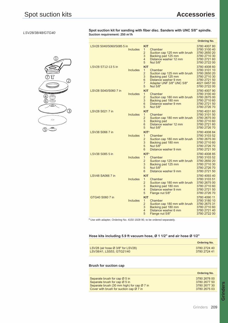
Grinders 209
j
Grin
ders
Spot suction kits Accessories
LSV28/38/48/GTG40Spot suction kit for sanding with fiber disc. Sanders with UNC 5/8" spindle.Suction requirement: 250 m3/h
a Use with adapter, Ordering No. 4150 1928 90, to be ordered separately.
o
pk
l
m
n
Hose kits including 5.9 ft vacuum hose, Ø 1 1/2" and air hose Ø 1/2"
Ordering No.
LSV28 (air hose Ø 3/8" for LSV28) 3780 2724 40LSV38/41, LSS53, GTG21/40 3780 2724 41
Brush for suction cap
Ordering No.
Separate brush for cap Ø 5 in 3780 2678 00Separate brush for cap Ø 5 in 3780 2677 50Separate brush (30 mm high) for cap Ø 7 in 3780 2677 30Cover with brush for suction cap Ø 7 in 3780 2675 03
Ordering No.
LSV28 S040/S060/S085 5 in KIT 3780 4007 80 Includes 1 Chamber 3780 3100 40 2 Suction cap 125 mm with brush 3780 2650 20 3 Backing pad 125 mm 3780 2710 30 4 Distance washer 12 mm 3780 2721 60 5 Nut 5/8" 3780 2722 00LSV28 ST12-13 5 in KIT 3780 4008 60 Includes 1 Chamber 3780 3101 10 2 Suction cap 125 mm with brush 3780 2650 20 3 Backing pad 125 mm 3780 2710 30 6 Distance washer 9 mm 3780 2721 50 7 Adapter UNF 3/8" UNC 5/8" 4021 0457 00 5 Nut 5/8" 3780 2722 00LSV28 S040/S060 7 in KIT 3780 4007 90 Includes 1 Chamber 3780 3100 40 2 Suction cap 180 mm with brush 3780 2675 00 3 Backing pad 180 mm 3780 2710 60 6 Distance washer 9 mm 3780 2721 50 5 Nut 5/8" 3780 2726 70LSV28 S021 7 in KIT 3780 4031 60 Includes 1 Chamber 3780 3101 50 2 Suction cap 180 mm with brush 3780 2675 00 3 Backing pad 3780 2710 60 6 Distance washer 12 mm 3780 2721 60 5 Nut 5/8" 3780 2726 70LSV38 S066 7 in KITa 3780 4008 84 Includes 1 Chamber 3780 3103 52 2 Suction cap 180 mm with brush 3780 2675 00 3 Backing pad 180 mm 3780 2710 60 5 Nut 5/8" 3780 2726 70 6 Distance washer 9 mm 3780 2721 50LSV38 S085 5 in KITa 3780 4008 85 Includes 1 Chamber 3780 3103 52 2 Suction cap 125 mm with brush 3780 2650 20 3 Backing pad 125 mm 3780 2710 30 5 Nut 5/8" 3780 2726 70 6 Distance washer 9 mm 3780 2721 50LSV48 SA066 7 in KIT 3780 4093 40 Includes 1 Chamber 3780 3103 51 2 Suction cap 180 mm with brush 3780 2675 00 3 Backing pad 180 mm 3780 2710 60 4 Distance washer 9 mm 3780 2721 50 5 Flange nut 5/8" 3780 2726 70GTG40 S060 7 in KIT 3780 4090 11 Includes 1 Chamber 3780 3180 10 2 Suction cap 180 mm with brush 3780 2675 31 3 Backing pad 180 mm 3780 2710 60 4 Distance washer 6 mm 3780 2721 40 5 Flange nut 5/8" 3780 2722 00
Am_Grinders.indd 209 2012-02-07 12:18:00

210 Grinders
5
2
12
4009560
11
1
4009150
Grin
ders
Accessories Spot suction kits
Kit for GRP-cutting
Ordering No.
LSV48 SA085/SA066 7 in KIT 3780 4093 42 Includes 2 Suction chamber, complete 3780 3103 54 5 Gable cover plate, complete 3780 2732 20 11 Spacer 10 mm 3780 2726 60 12 Flange set 3780 2799 50 Optional 7 in cutting-off disc 3780 5074 62
LSV48
Spot suction kit for die grindersSuction requirement: 125 m3/h (LSF18), 200 m3/h (LSF28)
Ordering No.
LSF18 S 1 Chamber for burr 3780 3015 22
LSF28 S KIT for burr 3780 4007 42 Includes 1 Chamber 3780 3078 90 1a Nozzle 3780 2730 10
LSV18 S-1 KIT for sanding pad dia 50 and 75 mm 3780 4092 62 Includes 2 O-ring 23x1.6 0663 2103 85 3 Clamp ring 4112 1065 04 4 Flow chamber 3780 3027 61 5 Lock screw M4x6 A1 0192 1168 00 6 Lock pin 4112 0779 00 7 Suction cap 50 mm 3780 2782 90 8 Suction cap 75 mm 3780 2782 91 9 Hexagon wrench 2 mm 3780 9902 10
j
jA
o
p
k
l
mn
q
kr
Am_Grinders.indd 210 2012-02-07 12:18:01
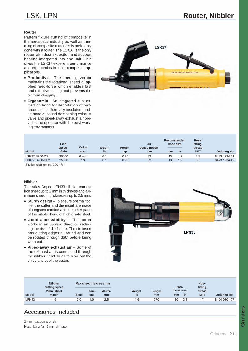
Grinders 211
Grin
ders
RouterPattern fixture cutting of composite in the aerospace industry as well as trim- ming of com pos ite materials is pref er a bly done with a router. The LSK37 is the only rout er with dust extraction and sup port bearing in te grat ed into one unit. This gives the LSK37 ex cel lent per form ance and er go nom ics in most com pos ite ap- pli ca tions.l Productive – The speed governor
main tains the rotational speed at ap- plied feed-force which enables fast and ef fec tive cut ting and prevents the bit from clogging.
l Ergonomic – An integrated dust ex- trac tion hood for deportation of haz- ard ous dust, thermally insulated throt- tle handle, sound dampening exhaust valve and piped-away exhaust air pro- vides the operator with the best work- ing environment.
NibblerThe Atlas Copco LPN33 nibbler can cut iron sheet up to 2 mm in thickness and alu-minum sheet in thicknesses up to 2.5 mm.l Sturdy design – To ensure optimal tool
life, the cutter and die insert are made of tungsten carbide and the oth er parts of the nibbler head of high-grade steel.
l Good accessibility – The cutter works in an upward direction re duc- ing the risk of die failure. The die in sert has cut ting edg es all round and can be ro tat ed through 360o before being worn out.
l Piped-away exhaust air – Some of the exhaust air is conducted through the nibbler head so as to blow out the chips and cool the cutter.
3 mm hexagon wrenchHose fi tting for 10 mm air hose
LSK, LPN Router, Nibbler
Accessories Included
Recommended Hose Free Air hose size fi tting speed Collet Weight Power consumption thread Model r/min size lb hp cfm mm in NPT Ordering No.LSK37 S250-DS1 25000 6 mm 6.1 0.95 32 13 1/2 3/8 8423 1234 41LSK37 S250-DS2 25000 1/4 6.1 0.95 32 13 1/2 3/8 8423 1234 42Suction requirement: 200 m3/h.
Nibbler Max sheet thickness mm Hose cutting speed Rec. fi tting 2 mm sheet Stain- Alumi- Weight Length hose size thread Model m/min Steel less num lb mm mm in NPT Ordering No.LPN33 1.6 2.0 1.0 2.5 4.6 270 10 3/8 1/4 8424 0301 07
Am_Grinders.indd 211 2012-02-07 12:18:02
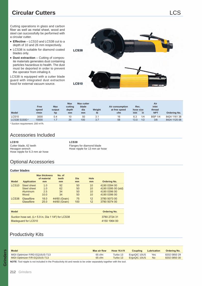
212 Grinders
Grin
ders
Cutting operations in glass and carbon fi ber as well as metal sheet, wood and steel can successfully be performed with a cir cu lar cutter.l Effective – LCS10 and LCS38 cut to a
depth of 10 and 26 mm respectively.l LCS38 is suitable for diamond coat ed
blades only.l Dust extraction – Cutting of com pos-
ite materials generates dust con tain ing particles hazardous to health. The dust must be deported in order to pre vent the operator from inhaling it.
LCS38 is equipped with a cutter blade guard with integrated dust extraction hood for external vacuum source.
Max Max cutter Air Free Max cutting blade Air consumption Rec. inlet speed output depth dia Weight at free speed hose size thread Model r/min hp mm mm lb cfm mm in NPT Or der ing No.LCS10 3000 0.4 10 50 3.1 16 6.3 1/4 BSP 1/4 8424 1161 38LCS38 S150D a 15000 1.7 26 100 3.7 58 13.0 1/2 3/8 8424 1125 06
LCS10Cutter blade, 62 teethHexagon wrenchHose nipple for 6.3 mm air hose
a Suction requirement: 200 m3/h.
Cutter blades Max thickness No. of of material teeth Dia HoleModel Application mm mm mm mm Or der ing No.LCS10 Steel sheet 1.0 92 50 10 4190 0394 00 Steel sheet 1.0 62 50 10 4190 0395 00 (std) Aluminum 2.5 34 50 10 4190 0396 00 Wood 10.0 34 50 10 4190 0396 00LCS38 Glassfi bre 18.0 44/60 (Grain) 75 12 3780 5073 00 Glassfi bre 25.0 44/60 (Grain) 100 12 3780 5074 00
Circular Cutters LCS
Accessories Included
Optional Accessories
LCS38Flanges for diamond bladeHose nipple for 13 mm air hose
Model Ordering No.
Suction hose set, (L= 5.9 in, Dia 1 1/4") for LCS38 3780 2724 31Bladeguard for LCS10 4150 1964 00
Productivity Kits
NOTE: Tool nipple is not included in the Productivity kit and needs to be order separately together with the tool.
Model Max air fl ow Hose 16.4 ft Coupling Lubrication Ordering No.MIDI Optimizer F/RD EQ10US-T13 65 cfm Turbo 13 ErgoQIC 10US Yes 8202 0850 29MIDI Optimizer F/R EQ10US-T13 65 cfm Turbo 13 ErgoQIC 10US No 8202 0850 30
Am_Grinders.indd 212 2012-02-07 12:18:03

Percussive Tools
Contents PageIntroduction ........................................ 214Product safety.................................... 215Chipping hammers ............................ 216Scalers............................................... 218Rammers ........................................... 221Riveting systems ............................... 222Riveting hammers.............................. 223Bucking bars ...................................... 225Chisels ............................................... 227
Am_Percussive.indd 213 2012-02-07 13:33:49

Perc
ussi
ve T
ools
214 Percussive Tools
Introduction – Percussive Tools
Atlas Copco percussive tools are ideal for all material removal tasks in foun-dries, engineering workshops, shipyards, and the construction and off-shore industries. Built-in-ergonomic features such as vibration damping reduce the human load, delay fatigue and help protect the operator against the ill effects of long-term exposure to vibration and noise. Vibration-damped models are available over almost the entire power range.
ChippingGeneral chipping and multipurpose “chiseling” in heavy industrial use. Fet-tling of castings in foundries. Offshore and shipyard applications.
Efficient – For highest efficiency, choose tools with a high power-to-weight ratio. RRF 21/31 have an excellent ma-terial removal rate.
Well proven design. Simple and well proven design for a long, trouble-free tool life.
The conventional RRC 22 – 75 range models, which have forged steel han-dles, are basic versions with excellent handling and reliability.
Vibration damped chippers are easy on your operators. The RRF and RRD models are vibration damped.
The designs use lightweight alloys to keep tool weight down while maintaining performance.
This makes these tools extremely ef-fective in the hands of your skilled opera-tors.
Weld flux removalApplications – Fettling welds from flux and spatter. General scaling operations.The tools – Modern welding methods generate slag that is easily removed and almost no spatter. In these applications RVM 07B is the right choice. It has pow-er enough to do the job, very low noise and is vibration damped below 2.5 m/s2. The standard chisel delivered with the tool is carbide tipped for a long service life. The tool is also equipped with clean blowing capacity.
For heavy slag chipping and tougher scaling the conventional scaler RRC 13 and RRC 13B with a blowing function arethe preferred models. These tools have the right power for this type of job and a sturdy reliable design. The gripping diameter is only 45 mm, including the throttle lever. They also have a low vibra-tion level for conventional models.
Rust and paint removalThe tools are suitable for rust and paint removal in segments like industrial main-tenance, shipyards and in the offshore industry.
For lighter jobs the needle scaler RRC 13 is the ideal tool. Needle sets of differ-ent shapes and material are available to suit most operations.
These tools make light of the toughest jobs
Am_Percussive.indd 214 2012-02-07 13:34:01

Perc
ussi
ve T
ools
Percussive Tools 215
Product Safety
AVOID ACCIDENTS
The chisel, die or punch may fall out or may be shot out of the tool accidentally causing serious injury.
� Be aware that the chisel may break during operation.
� Never trigger a hammer unless held against a work piece.
� Remove chisel, die or punch from tool when work is over.
� When finishing a job, discon-nect the tool from its air supply.
� Before changing accessories, chisel or die – disconnect the tool from the air supply.
Chips and sparks should be prevented from striking an eye or another worker.
To prevent vision loss:� Always wear eye protection.� Isolate work of this kind by us-
ing barriers between work sta-tions.
� Do not use the tool for other pur-poses than it is intended for.
Gloves protect fi ngers from pinching, scuffi ng and scraping.
� Protectives shoes may prevent your feet from being injured.
Explosive atmosphere must not be ignited.
To prevent injury and property loss from fi res:� Use other technique.� Use accessories of non sparking
material (e.g. needle attachment of Beryllium copper for a needle scaler).
Electric shock may be fatal.� Avoid chiseling into electric wiring hidden inside walls etc.
LONG TERM RISKS
Always use ear protection.
Vibration may be harmful to hands and arms.
Dust generated during operation may be harmful.� Use spot suction or a breathing
apparatus.
PROPER USE AND MAINTENANCE
Do not perform idle blows with a hammer.
� They will cause high internal stresses and shorten the life of the tool.
� Note the risk of shooting out the chisel, die or punch if the retain-er is not in order or damaged.
Quick coupling.
Follow the tool manual and the lubrication instructions.
Perform overhauls at regular intervals.
� Use vibration dampened tools if available.
� Reduce the total time of expo-sure to vibrations, particularly if the operator has to guide the chisel by hand.
To prevent gradual loss of hearing due to exposure to high noise level – wear ear protection.
To prevent injury from a fl ying chisel:� Always use a retainer.� Inspect the retainer for wear or
damage regularly.
� If a coupling is used on a per-cussive tool, it should be sepa-rated from the tool by a whip hose (length 0.5 m).
IMPORTANT: All local safety regulations with respect to installation, operation and overhaul must always be followed.
1
2
3
4
5
6
7
8
10
11
12
9
Am_Percussive.indd 215 2012-02-07 13:34:13
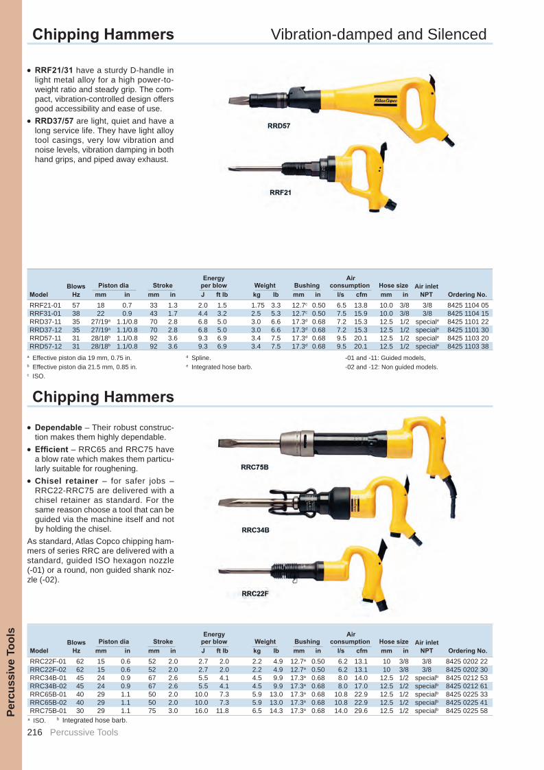
Perc
ussi
ve T
ools
216 Percussive Tools
Energy Air Blows Piston dia Stroke per blow Weight Bushing consumption Hose size Air inletModel Hz mm in mm in J ft lb kg lb mm in l/s cfm mm in NPT Ordering No.RRC22F-01 62 15 0.6 52 2.0 2.7 2.0 2.2 4.9 12.7a 0.50 6.2 13.1 10 3/8 3/8 8425 0202 22RRC22F-02 62 15 0.6 52 2.0 2.7 2.0 2.2 4.9 12.7a 0.50 6.2 13.1 10 3/8 3/8 8425 0202 30RRC34B-01 45 24 0.9 67 2.6 5.5 4.1 4.5 9.9 17.3a 0.68 8.0 14.0 12.5 1/2 specialb 8425 0212 53RRC34B-02 45 24 0.9 67 2.6 5.5 4.1 4.5 9.9 17.3a 0.68 8.0 17.0 12.5 1/2 specialb 8425 0212 61RRC65B-01 40 29 1.1 50 2.0 10.0 7.3 5.9 13.0 17.3a 0.68 10.8 22.9 12.5 1/2 specialb 8425 0225 33RRC65B-02 40 29 1.1 50 2.0 10.0 7.3 5.9 13.0 17.3a 0.68 10.8 22.9 12.5 1/2 specialb 8425 0225 41RRC75B-01 30 29 1.1 75 3.0 16.0 11.8 6.5 14.3 17.3a 0.68 14.0 29.6 12.5 1/2 specialb 8425 0225 58
Energy Air Blows Piston dia Stroke per blow Weight Bushing consumption Hose size Air inletModel Hz mm in mm in J ft lb kg lb mm in l/s cfm mm in NPT Ordering No.RRF21-01 57 18 0.7 33 1.3 2.0 1.5 1.75 3.3 12.7c 0.50 6.5 13.8 10.0 3/8 3/8 8425 1104 05RRF31-01 38 22 0.9 43 1.7 4.4 3.2 2.5 5.3 12.7c 0.50 7.5 15.9 10.0 3/8 3/8 8425 1104 15RRD37-11 35 27/19a 1.1/0.8 70 2.8 6.8 5.0 3.0 6.6 17.3d 0.68 7.2 15.3 12.5 1/2 speciale 8425 1101 22RRD37-12 35 27/19a 1.1/0.8 70 2.8 6.8 5.0 3.0 6.6 17.3d 0.68 7.2 15.3 12.5 1/2 speciale 8425 1101 30RRD57-11 31 28/18b 1.1/0.8 92 3.6 9.3 6.9 3.4 7.5 17.3d 0.68 9.5 20.1 12.5 1/2 speciale 8425 1103 20RRD57-12 31 28/18b 1.1/0.8 92 3.6 9.3 6.9 3.4 7.5 17.3d 0.68 9.5 20.1 12.5 1/2 speciale 8425 1103 38
Chipping Hammers Vibration-damped and Silenced
a Effective piston dia 19 mm, 0.75 in.b Effective piston dia 21.5 mm, 0.85 in.c ISO.
-01 and -11: Guided models,-02 and -12: Non guided models.
Chipping Hammers
� RRF21/31 have a sturdy D-handle in light metal alloy for a high power-to-weight ratio and steady grip. The com-pact, vibration-controlled design offers good accessibility and ease of use.
� RRD37/57 are light, quiet and have a long service life. They have light alloy tool casings, very low vibration and noise levels, vibration damping in both hand grips, and piped away exhaust.
d Spline.e Integrated hose barb.
� Dependable – Their robust construc-tion makes them highly dependable.
� Effi cient – RRC65 and RRC75 have a blow rate which makes them particu-larly suitable for roughening.
� Chisel retainer – for safer jobs – RRC22-RRC75 are delivered with a chisel retainer as standard. For the same reason choose a tool that can be guided via the machine itself and not by holding the chisel.
As standard, Atlas Copco chipping ham-mers of series RRC are delivered with a standard, guided ISO hexagon nozzle (-01) or a round, non guided shank noz-zle (-02).
a ISO. b Integrated hose barb.
Am_Percussive.indd 216 2012-02-07 13:34:15
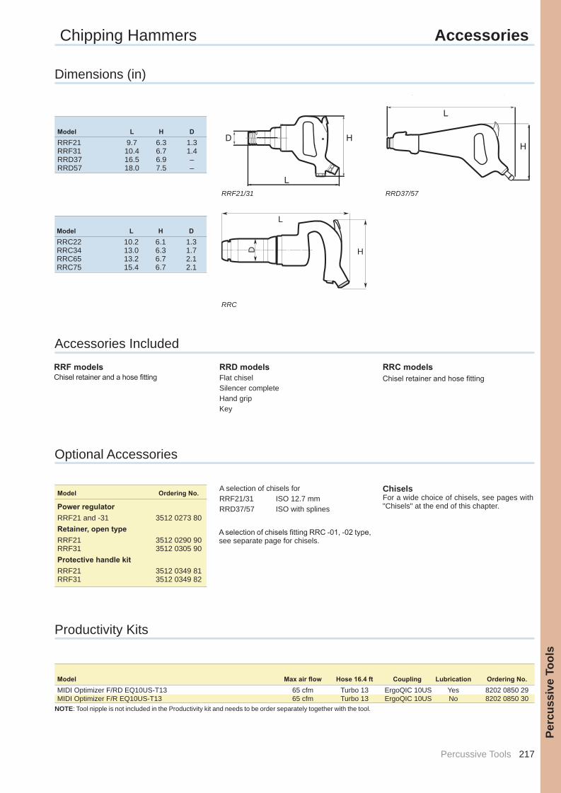
Perc
ussi
ve T
ools
Percussive Tools 217
RRF21/31 RRD37/57
D
L
H
RRC
Model Max air flow Hose 16.4 ft Coupling Lubrication Ordering No.MIDI Optimizer F/RD EQ10US-T13 65 cfm Turbo 13 ErgoQIC 10US Yes 8202 0850 29MIDI Optimizer F/R EQ10US-T13 65 cfm Turbo 13 ErgoQIC 10US No 8202 0850 30
Model L H DRRC22 10.2 6.1 1.3RRC34 13.0 6.3 1.7RRC65 13.2 6.7 2.1RRC75 15.4 6.7 2.1
Model L H DRRF21 9.7 6.3 1.3RRF31 10.4 6.7 1.4RRD37 16.5 6.9 –RRD57 18.0 7.5 –
A selection of chisels forRRF21/31 ISO 12.7 mmRRD37/57 ISO with splines
Accessories Included
A selection of chisels fitting RRC -01, -02 type, see separate page for chisels.
Optional Accessories
Dimensions (in)
Chipping Hammers Accessories
ChiselsFor a wide choice of chisels, see pages with "Chisels" at the end of this chapter.
RRF modelsChisel retainer and a hose fitting
RRD modelsFlat chiselSilencer completeHand gripKey
RRC modelsChisel retainer and hose fitting
Model Ordering No.
Power regulatorRRF21 and -31 3512 0273 80Retainer, open typeRRF21 3512 0290 90RRF31 3512 0305 90Protective handle kitRRF21 3512 0349 81RRF31 3512 0349 82
Productivity Kits
NOTE: Tool nipple is not included in the Productivity kit and needs to be order separately together with the tool.
Am_Percussive.indd 217 2012-02-07 13:34:16
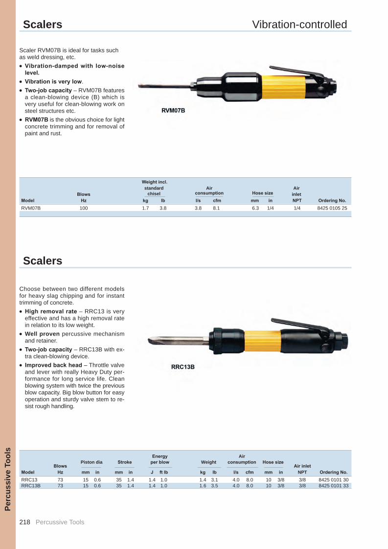
Perc
ussi
ve T
ools
218 Percussive Tools
Weight incl. standard Air Air Blows chisel consumption Hose size inletModel Hz kg lb l/s cfm mm in NPT Ordering No.RVM07B 100 1.7 3.8 3.8 8.1 6.3 1/4 1/4 8425 0105 25
Scaler RVM07B is ideal for tasks such as weld dressing, etc.� Vibration‑damped with low‑noise
level.� Vibration is very low.� Two‑job capacity – RVM07B features
a clean-blowing device (B) which is very useful for clean-blowing work on steel structures etc.
� RVM07B is the obvious choice for light concrete trimming and for removal of paint and rust.
Scalers
Choose between two different models for heavy slag chipping and for instant trimming of concrete.� High removal rate – RRC13 is very
effective and has a high removal rate in relation to its low weight.
� Well proven percussive mechanism and retainer.
� Two‑job capacity – RRC13B with ex-tra clean-blowing device.
� Improved back head – Throttle valve and lever with really Heavy Duty per-formance for long service life. Clean blowing system with twice the previous blow capacity. Big blow button for easy operation and sturdy valve stem to re-sist rough handling.
Energy Air Piston dia Stroke per blow Weight consumption Hose size Blows Air inletModel Hz mm in mm in J ft lb kg lb l/s cfm mm in NPT Ordering No.RRC13 73 15 0.6 35 1.4 1.4 1.0 1.4 3.1 4.0 8.0 10 3/8 3/8 8425 0101 30RRC13B 73 15 0.6 35 1.4 1.4 1.0 1.6 3.5 4.0 8.0 10 3/8 3/8 8425 0101 33
Scalers Vibration-controlled
Am_Percussive.indd 218 2012-02-07 13:34:17
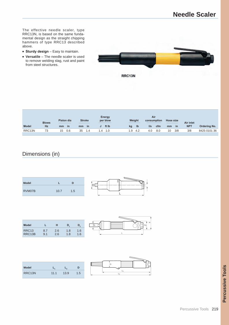
Perc
ussi
ve T
ools
Percussive Tools 219
D
L
L
D
H
1 2D
L
L
1
2
D
The effective needle scaler, type RRC13N, is based on the same funda-mental design as the straight chipping hammers of type RRC13 described above.� Sturdy design – Easy to maintain.� Versatile – The needle scaler is used
to remove welding slag, rust and paint from steel structures.
Energy Air Piston dia Stroke per blow Weight consumption Hose size Blows Air inletModel Hz mm in mm in J ft lb kg lb l/s cfm mm in NPT Ordering No.RRC13N 73 15 0.6 35 1.4 1.4 1.0 1.9 4.2 4.0 8.0 10 3/8 3/8 8425 0101 36
Needle Scaler
Model L D
RVM07B 10.7 1.5
Model L1 L2 D
RRC13N 11.1 13.9 1.5
Model L H D1 D2
RRC13 8.7 2.6 1.8 1.6RRC13B 9.1 2.6 1.8 1.6
Dimensions (in)
Am_Percussive.indd 219 2012-02-07 13:34:18
Perc
ussi
ve T
ools
220 Percussive Tools
For RMV07BCarbide tipped chisels and through hardened chisels with other length and width, see sepa-rate page for chisels.
For RRC13N Needle‑set of 19 needles, length 100 mm
Material Ordering No.
Steel, standard 3510 0221 90Steel flat ends 3510 0227 90Stainless steel flat ends 3510 0228 90Beryllium copper flat ends(spark resistant) 3510 0229 90
RRC13 / RRC13B Ordering No.
Hand guard 3510 0246 90All steel retainer 3510 0245 80Silencer 3510 0366 80
For RRC13, 13B
Accessories Included
For all RRC13Hose fittingScaling chisel
Optional Accessories
Chisels for RRC13 and -13B:Square shank 13.0 mm
For RMV07BHose fittingFlat carbide tipped chisel 10x120 mm
Accessories Scalers
Model Max air flow Hose 16.4 ft Coupling Lubrication Ordering No.MIDI Optimizer F/RD EQ10US-T13 65 cfm Turbo 13 ErgoQIC 10US Yes 8202 0850 29MIDI Optimizer F/R EQ10US-T13 65 cfm Turbo 13 ErgoQIC 10US No 8202 0850 30
Productivity Kits
NOTE: Tool nipple is not included in the Productivity kit and needs to be order separately together with the tool.
Am_Percussive.indd 220 2012-02-07 13:34:18
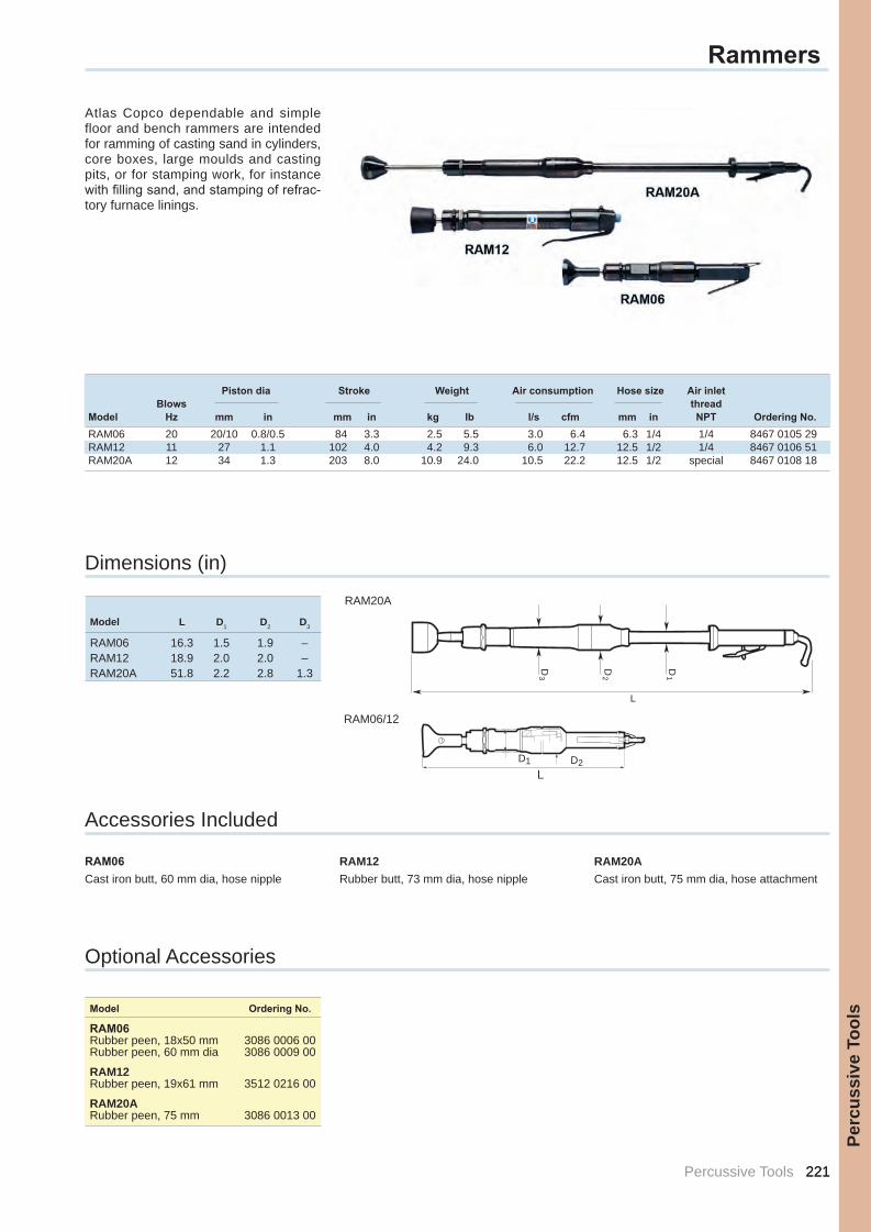
221
Perc
ussi
ve T
ools
Percussive Tools 221
D1
D3
D2
L
LD1 D2
RAM06/12
RAM20A
Accessories Included
Atlas Copco dependable and simple floor and bench rammers are intended for ramming of casting sand in cylinders, core boxes, large moulds and casting pits, or for stamping work, for instance with fi lling sand, and stamping of refrac-tory furnace linings.
Piston dia Stroke Weight Air consumption Hose size Air inlet Blows threadModel Hz mm in mm in kg lb l/s cfm mm in NPT Ordering No.RAM06 20 20/10 0.8/0.5 84 3.3 2.5 5.5 3.0 6.4 6.3 1/4 1/4 8467 0105 29RAM12 11 27 1.1 102 4.0 4.2 9.3 6.0 12.7 12.5 1/2 1/4 8467 0106 51RAM20A 12 34 1.3 203 8.0 10.9 24.0 10.5 22.2 12.5 1/2 special 8467 0108 18
Rammers
Optional Accessories
Model Ordering No.
RAM06Rubber peen, 18x50 mm 3086 0006 00Rubber peen, 60 mm dia 3086 0009 00
RAM12Rubber peen, 19x61 mm 3512 0216 00
RAM20ARubber peen, 75 mm 3086 0013 00
Dimensions (in)
Model L D1 D2 D3
RAM06 16.3 1.5 1.9 –RAM12 18.9 2.0 2.0 –RAM20A 51.8 2.2 2.8 1.3
RAM06Cast iron butt, 60 mm dia, hose nipple
RAM12Rubber butt, 73 mm dia, hose nipple
RAM20ACast iron butt, 75 mm dia, hose attachment
Am_Percussive.indd 221 2012-02-07 13:34:19
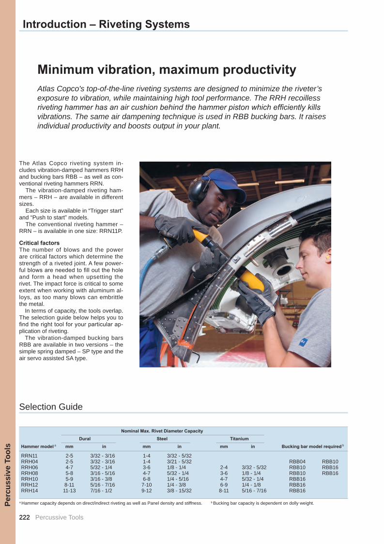
222
Perc
ussi
ve T
ools
222 Percussive Tools
Nominal Max. Rivet Diameter Capacity Dural Steel TitaniumHammer model a mm in mm in mm in Bucking bar model required b
RRN11 2-5 3/32 - 3/16 1-4 3/32 - 5/32RRH04 2-5 3/32 - 3/16 1-4 3/21 - 5/32 RBB04 RBB10RRH06 4-7 5/32 - 1/4 3-6 1/8 - 1/4 2-4 3/32 - 5/32 RBB10 RBB16RRH08 5-8 3/16 - 5/16 4-7 5/32 - 1/4 3-6 1/8 - 1/4 RBB10 RBB16RRH10 5-9 3/16 - 3/8 6-8 1/4 - 5/16 4-7 5/32 - 1/4 RBB16RRH12 8-11 5/16 - 7/16 7-10 1/4 - 3/8 6-9 1/4 - 1/8 RBB16RRH14 11-13 7/16 - 1/2 9-12 3/8 - 15/32 8-11 5/16 - 7/16 RBB16
Introduction – Riveting Systems
The Atlas Copco riveting system in-cludes vibration-damped hammers RRH and bucking bars RBB – as well as con-ventional riveting hammers RRN.
The vibration-damped riveting ham-mers – RRH – are available in different sizes.
Each size is available in “Trigger start” and “Push to start” models.
The conventional riveting hammer – RRN – is available in one size: RRN11P.
Critical factorsThe number of blows and the power are critical factors which determine the strength of a riveted joint. A few power-ful blows are needed to fill out the hole and form a head when upsetting the rivet. The impact force is critical to some extent when working with aluminum al-loys, as too many blows can embrittle the metal.
In terms of capacity, the tools overlap. The selection guide below helps you to find the right tool for your particular ap-plication of riveting.
The vibration-damped bucking bars RBB are available in two versions – the simple spring damped – SP type and the air servo assisted SA type.
a Hammer capacity depends on direct/indirect riveting as well as Panel density and stiffness.
Selection Guide
Minimum vibration, maximum productivityAtlas Copco's top-of-the-line riveting systems are designed to minimize the riveter’s exposure to vibration, while maintaining high tool performance. The RRH recoilless riveting hammer has an air cushion behind the hammer piston which efficiently kills vibrations. The same air dampening technique is used in RBB bucking bars. It raises individual productivity and boosts output in your plant.
b Bucking bar capacity is dependent on dolly weight.
Am_Percussive.indd 222 2012-02-07 13:34:31
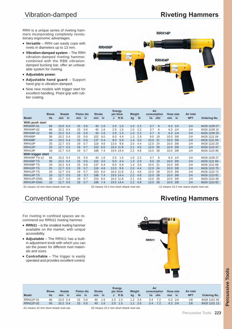
223
Perc
ussi
ve T
ools
Percussive Tools 223
Energy Air Blows Nozzle Piston dia Stroke per blow Weight consumption Hose size Air inletModel Hz mm in mm in mm in J ft lb kg lb l/s cfm mm in NPT Ordering No.RRN11P-01 66 10.0 0.4 15 0.6 40 1.6 2.0 1.5 1.2 2.6 3.4 7.2 6.3 1/4 1/8 8426 1101 05RRN11P-02 66 10.2 0.4 15 0.6 40 1.6 2.0 1.5 1.2 2.6 3.4 7.2 6.3 1/4 1/8 8426 1101 13
For riveting in confined spaces we re-commend our RRN11 riveting hammer.� RRN11 – is the smallest riveting hammer
available on the market, with unique accessibility.
� Adjustable – The RRN11 has a built-in adjustment knob with which you can set the power for different rivet materi-als and sizes.
� Controllable – The trigger is easily operated and provides excellent control.
-01 means 10 mm short shank rivet set.
Conventional Type Riveting Hammers
RRH is a unique series of riveting ham-mers incorporating completely revolu-tionary ergonomic advantages.� Versatile – RRH can easily cope with
rivets in diameters up to 13 mm.� Vibration‑damped system – The RRH
vibration-damped riveting hammer, combined with the RBB vibration-damped bucking bar, offer an unbeat-able system for riveting.
� Adjustable power.� Adjustable hand guard – Support
hand grip is vibration-damped.� Now new models with trigger start for
excellent handling. Pistol grip with rub-ber coating.
-01 means 10 mm short shank rivet set.
Energy Air Blows Nozzle Piston dia Stroke per blow Weight consumption Hose size Air inletModel Hz mm in mm in mm in J ft lb kg lb l/s cfm mm in NPT Ordering No.With push startRRH04P-01 66 10.0 0.4 15 0.6 40 1.6 2.0 1.5 1.0 2.2 3.7 6 6.3 1/4 1/4 8426 1109 07RRH04P-02 66 10.2 0.4 15 0.6 40 1.6 2.0 1.5 1.0 2.2 3.7 6 6.3 1/4 1/4 8426 1109 15RRH04P-12 66 10.2 0.4 15 0.6 40 1.6 2.0 1.5 1.0 2.2 3.7 6 6.3 1/4 1/4 8426 1109 25RRH06P 36 10.2 0.4 15 0.6 102 4.0 6.0 4.4 1.3 2.9 9.0 19 10.0 3/8 1/4 8426 1111 04RRH08P 24 10.2 0.4 15 0.6 137 5.4 8.0 5.9 1.4 3.0 10.0 21 10.0 3/8 1/4 8426 1111 09RRH10P 25 12.7 0.5 19 0.7 118 4.6 13.0 9.6 2.0 4.4 12.0 24 10.0 3/8 1/4 8426 1110 20RRH12P 20 12.7 0.5 19 0.7 153 6.0 16.0 11.8 2.1 4.6 13.0 28 10.0 3/8 1/4 8426 1110 47RRH14P 18 12.7 0.5 19 0.7 188 7.4 19.5 14.4 2.2 4.8 13.0 28 10.0 3/8 1/4 8426 1110 80With trigger startRRH04P TS-12 66 10.2 0.4 15 0.6 40 1.6 2.0 1.5 1.0 2.2 3.7 6 6.3 1/4 1/4 8426 1109 27RRH06P TS 36 10.2 0.4 15 0.6 102 4.0 6.0 4.4 1.3 2.9 9.0 19 10.0 3/8 1/4 8426 1111 66RRH08P TS 24 10.2 0.4 15 0.6 137 5.4 8.0 5.9 1.4 3.0 10.0 21 10.0 3/8 1/4 8426 1111 68RRH10P TS 25 12.7 0.5 19 0.7 118 4.6 13.0 9.6 2.0 4.4 12.0 24 10.0 3/8 1/4 8426 1110 70RRH12P TS 20 12.7 0.5 19 0.7 153 6.0 16.0 11.8 2.1 4.6 13.0 28 10.0 3/8 1/4 8426 1110 72RRH14P TS 18 12.7 0.5 19 0.7 188 7.4 19.5 14.4 2.2 4.8 13.0 28 10.0 3/8 1/4 8426 1110 81RRH12P-ENG 20 12.7 0.5 19 0.7 153 6.0 16.0 11.8 2.1 4.6 13.0 28 10.0 3/8 1/4 8426 1110 49RRH14P-ENG 18 12.7 0.5 19 0.7 188 7.4 19.5 14.4 2.2 4.8 13.0 28 10.0 3/8 1/4 8426 1110 82
Vibration-damped Riveting Hammers
-02 means 10.2 mm short shank rivet set. -12 means 10.2 mm stand shank rivet set.
-02 means 10.2 mm short shank rivet set.
Am_Percussive.indd 223 2012-02-07 13:34:33

224
Perc
ussi
ve T
ools
224 Percussive Tools
28
12.7R19
29.5
10.2ISO
R13
17.5
10.2
R1.5
17.5
10.0
R1.5
Ø13
175
Ø13
200
L
H
CL
C
H
RRH RRN
River sets. RRH and RRN
Accessories Riveting Hammers
Optional Accessories
Accessories Included
Kits for conversion to trigger startoperationModel Ordering No.
RRH04P-12 3520 0363 80RRH06/08P 3520 0210 81RRH10/12P/14P 3520 0364 80
For RRN11PHose fitting and retainerBlank rivet set Retainers for blank and flush rivet set
Dimensions (in)
L H CModel in in inRRHRRH04-01 6.3 5.8 0.9RRH04-02 6.3 5.8 0.9RRH04-12 6.9 5.8 0.9RRH06 8.9 5.8 0.94RRH08P 9.6 5.8 0.94RRH10P 10.4 5.9 1.06RRH12P 11.8 5.9 1.06RRH14P 13.1 5.9 1.06RRNRRN11P 3.9 6.7 0.9
Shank Flush set Blank rivet setHammer type Model mm Ordering No. Ordering No.
RRH04P-01 (–01) 10.0 spec 3085 0347 00 3006 0983 00RRN11P-01
RRH04P-02 (–02) 10.2 spec 3085 0352 00 3085 0353 00RRN11P-02
RRH04P-12 (–12) 10.2 std 3085 0324 00 3085 0022 00RRH06P 10.2 stdRRH08P 10.2 std
RRH10P 12.7 std 3085 0323 00 3085 0021 00RRH12P 12.7 stdRRH14P 12.7 std Mandrel blank
RRH04P-12 10.2 std 3085 0212 00RRH06PRRH08P
RRH04P-12 10.2 std 3085 0212 02RRH06PRRH08P
For RRH modelsHose fittingFlush setOpen spring retainer
Am_Percussive.indd 224 2012-02-07 13:34:34
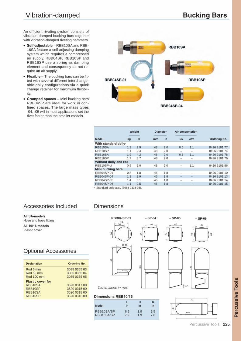
225
Perc
ussi
ve T
ools
Percussive Tools 225
RBB04 SP-01 – SP-04 – SP-0543
30
26
40
40
40
40
Ø 46
88
126
15o
– SP-06
40
40
40
126
C
H
L
An effi cient riveting system consists of vibration-damped bucking bars together with vibration-damped riveting hammers.� Self‑adjustable – RBB10SA and RBB-
16SA feature a self-adjusting damping system which requires a compressed air supply. RBB04SP, RBB10SP and RBB16SP use a spring as damping element and consequently do not re-quire an air supply.
� Flexible – The bucking bars can be fi t-ted with several different interchange-able dolly configurations via a quick change retainer for maximum fl exibil-ity.
� Cramped spaces – Mini bucking bars RBB04SP are ideal for work in con-fined spaces. The large mass types -04, -05 will in most applications set the rivet faster than the smaller models.
Weight Diameter Air consumption Model kg lb mm in l/s cfm Ordering No.With standard dollya
RBB10SA 1.3 2.9 48 2.0 0.5 1.1 8426 9101 77RBB10SP 1.1 2.4 48 2.0 – – 8426 9101 74RBB16SA 1.9 4.2 48 2.0 0.5 1.1 8426 9101 78RBB16SP 1.7 3.7 48 2.0 – – 8426 9101 76Without dolly and rodRBB10SP-U 0.9 2.0 48 2.0 – 1.1 8426 9101 86Mini bucking barsRBB04SP-01 0.8 1.8 46 1.8 – – 8426 9101 10RBB04SP-04 1.3 2.9 46 1.8 – – 8426 9101 13RBB04SP-05 1.4 3.1 46 1.8 – – 8426 9101 14RBB04SP-06 1.1 2.5 46 1.8 – – 8426 9101 15
Dimensions in mm
a Standard dolly assy (3085 0335 93).
Vibration-damped Bucking Bars
DimensionsAccessories Included
Optional Accessories
All SA‑modelsHose and hose fi tting
All 10/16 modelsPlastic cover
Dimensions RBB10/16
Designation Ordering No.
Rod 5 mm 3085 0365 03Rod 50 mm 3085 0365 04Rod 100 mm 3085 0365 05Plastic cover for RBB10SA 3520 0317 00RBB10SP 3520 0315 00RBB16SA 3520 0318 00RBB16SP 3520 0316 00
L H CModel in in in
RBB10SA/SP 6.5 1.9 5.5RBB16SA/SP 7.9 1.9 7.8
Am_Percussive.indd 225 2012-02-07 13:34:35
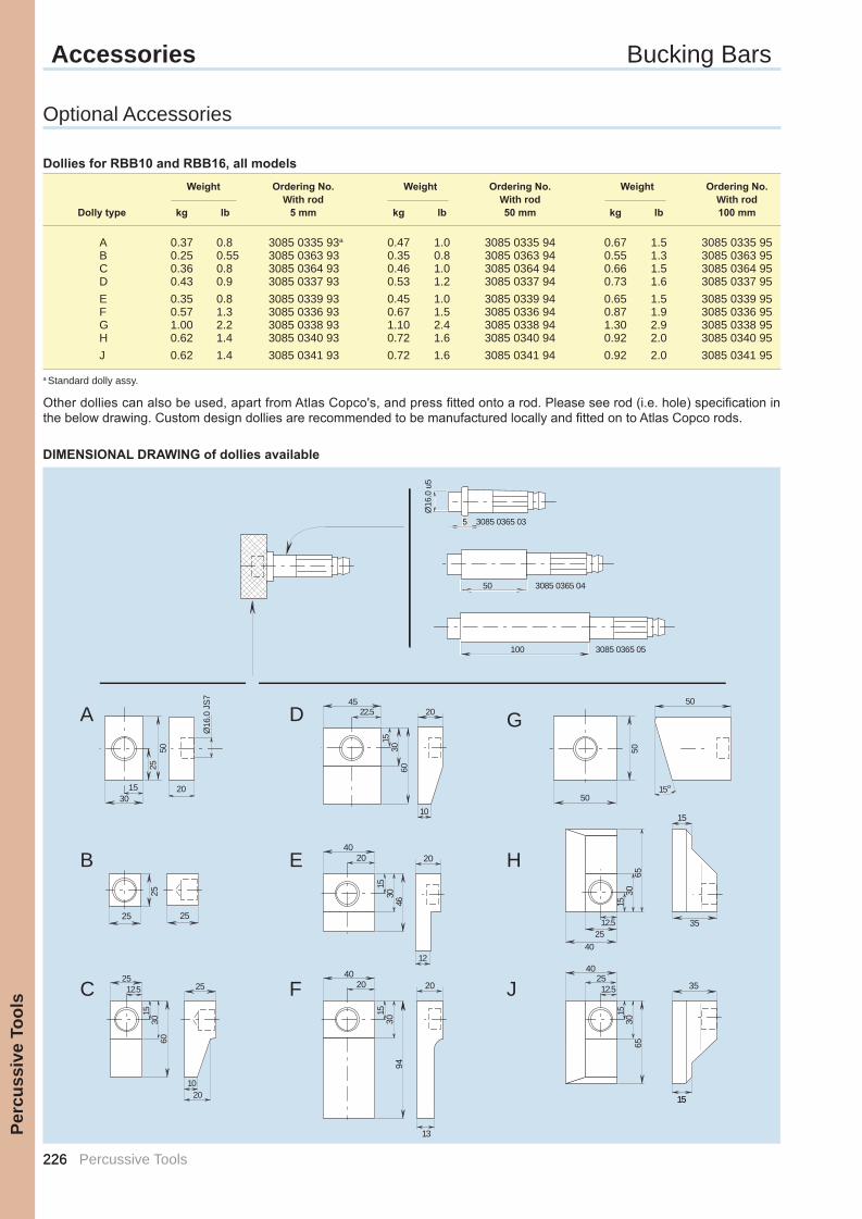
226
Perc
ussi
ve T
ools
226 Percussive Tools
Ø16
.0 u
5
5 3085 0365 03
100 3085 0365 05
50 3085 0365 04
30 15
25
50
Ø16
.0 J
S7
20
25
25
25
30 15
60
12.5 25
10 20
25
15
30
60
22.5 45
20
10
15
20 40
20
15
30
94
20 40
20
13
50
50
15 o
50
30 15
65
12.5 25
35
40
15
30
15
65
35
15
12
15
30
46
25
40
12.5
A
B
C
G
H
D
F J
E
Weight Ordering No. Weight Ordering No. Weight Ordering No. With rod With rod With rodDolly type kg lb 5 mm kg lb 50 mm kg lb 100 mm
A 0.37 0.8 3085 0335 93a 0.47 1.0 3085 0335 94 0.67 1.5 3085 0335 95B 0.25 0.55 3085 0363 93 0.35 0.8 3085 0363 94 0.55 1.3 3085 0363 95C 0.36 0.8 3085 0364 93 0.46 1.0 3085 0364 94 0.66 1.5 3085 0364 95D 0.43 0.9 3085 0337 93 0.53 1.2 3085 0337 94 0.73 1.6 3085 0337 95E 0.35 0.8 3085 0339 93 0.45 1.0 3085 0339 94 0.65 1.5 3085 0339 95F 0.57 1.3 3085 0336 93 0.67 1.5 3085 0336 94 0.87 1.9 3085 0336 95G 1.00 2.2 3085 0338 93 1.10 2.4 3085 0338 94 1.30 2.9 3085 0338 95H 0.62 1.4 3085 0340 93 0.72 1.6 3085 0340 94 0.92 2.0 3085 0340 95J 0.62 1.4 3085 0341 93 0.72 1.6 3085 0341 94 0.92 2.0 3085 0341 95
DIMENSIONAL DRAWING of dollies available
Dollies for RBB10 and RBB16, all models
a Standard dolly assy.
Accessories Bucking Bars
Other dollies can also be used, apart from Atlas Copco's, and press fitted onto a rod. Please see rod (i.e. hole) specification in the below drawing. Custom design dollies are recommended to be manufactured locally and fitted on to Atlas Copco rods.
Optional Accessories
Am_Percussive.indd 226 2012-02-07 13:34:36
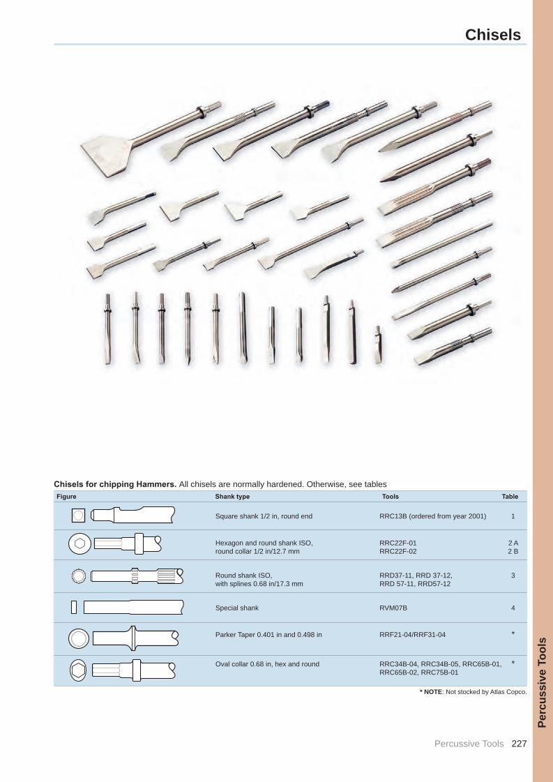
Perc
ussi
ve T
ools
Percussive Tools 227
Chisels
Chisels for chipping Hammers. All chisels are normally hardened. Otherwise, see tables
Square shank 1/2 in, round end RRC13B (ordered from year 2001) 1
Hexagon and round shank ISO, RRC22F-01 2 Around collar 1/2 in/12.7 mm RRC22F-02 2 B
Round shank ISO, RRD37-11, RRD 37-12, 3with splines 0.68 in/17.3 mm RRD 57-11, RRD57-12
Special shank RVM07B 4
Parker Taper 0.401 in and 0.498 in RRF21-04/RRF31-04 *
Oval collar 0.68 in, hex and round RRC34B-04, RRC34B-05, RRC65B-01, * RRC65B-02, RRC75B-01
Figure Shank type Tools Table
* NOTE: Not stocked by Atlas Copco.
Am_Percussive.indd 227 2012-02-07 13:34:38
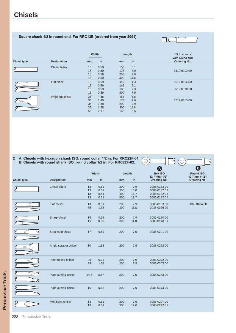
Perc
ussi
ve T
ools
228 Percussive Tools
Chisels
A B
A B
Width Length 1/2 in square with round endChisel type Designation mm in mm in Ordering No.
Chisel blank 15 0.59 155 6.1 15 0.59 178 7.0 3512 0113 00 15 0.59 200 7.9 15 0.59 300 11.8 Flat chisel 15 0.59 110 4.3 3512 0114 00 15 0.59 165 6.1 15 0.59 185 7.3 3512 0070 00 15 0.59 200 7.9 Wide flat chisel 35 1.38 165 6.5 35 1.40 178 7.0 3512 0115 00 35 1.38 200 7.9 35 1.38 300 11.8 55 2.17 165 6.5
Width Length Hex ISO Round ISO 12.7 mm (1/2") 12.7 mm (1/2")Chisel type Designation mm in mm in Ordering No. Ordering No.
Chisel blank 13 0.51 200 7.9 3085 0182 00 13 0.51 350 13.8 3085 0182 01 13 0.51 400 15.7 3085 0182 04 13 0.51 500 19.7 3085 0182 05
Flat chisel 13 0.51 200 7.9 3085 0183 00 3085 0184 00 35 1.38 300 11.8 3085 0376 00
Sharp chisel 15 0.59 200 7.9 3085 0170 00 15 0.59 300 11.8 3085 0170 01
Spot weld chisel 17 0.69 200 7.9 3085 0301 00
Angle scraper chisel 30 1.18 200 7.9 3085 0262 00
Pipe cutting chisel 20 0.78 200 7.9 3085 0302 00 35 1.38 200 7.9 3085 0303 00
Plate cutting chisel 14.5 0.57 200 7.9 3085 0263 00
Plate cutting chisel 16 0.62 200 7.9 3085 0173 00
Moil point chisel 13 0.51 200 7.9 3085 0297 00 13 0.51 305 12.0 3085 0297 01
2 A. Chisels with hexagon shank ISO, round collar 1/2 in. For RRC22F‑01. B. Chisels with round shank ISO, round collar 1/2 in. For RRC22F‑02.
1 Square shank 1/2 in round end. For RRC13B (ordered from year 2001)
Am_Percussive.indd 228 2012-02-07 13:34:39
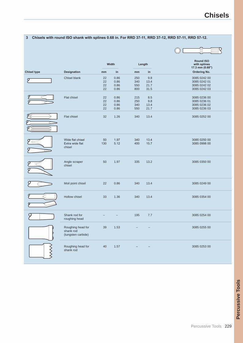
Perc
ussi
ve T
ools
Percussive Tools 229
Chisels
B
3 Chisels with round ISO shank with splines 0.68 in. For RRD 37‑11, RRD 37‑12, RRD 57‑11, RRD 57‑12.
Round ISO Width Length with splines 17.3 mm (0.68")Chisel type Designation mm in mm in Ordering No.
Chisel blank 22 0.86 250 9.8 3085 0242 00 22 0.86 340 13.4 3085 0242 01 22 0.86 550 21.7 3085 0242 02 22 0.86 800 31.5 3085 0242 03
Flat chisel 22 0.86 215 8.5 3085 0236 00 22 0.86 250 9.8 3085 0236 01 22 0.86 340 13.4 3085 0236 02 22 0.86 550 21.7 3085 0236 03
Flat chisel 32 1.26 340 13.4 3085 0252 00
Wide flat chisel 50 1.97 340 13.4 3085 0250 00 Extra wide flat 130 5.12 400 15.7 3085 0998 00 chisel
Angle scraper 50 1.97 335 13.2 3085 0350 00 chisel
Moil point chisel 22 0.86 340 13.4 3085 0249 00
Hollow chisel 33 1.36 340 13.4 3085 0354 00
Shank rod for – – 195 7.7 3085 0254 00 roughing head
Roughing head for 39 1.53 – – 3085 0255 00 shank rod (tungsten carbide)
Roughing head for 40 1.57 – – 3085 0253 00 shank rod
Am_Percussive.indd 229 2012-02-07 13:34:40
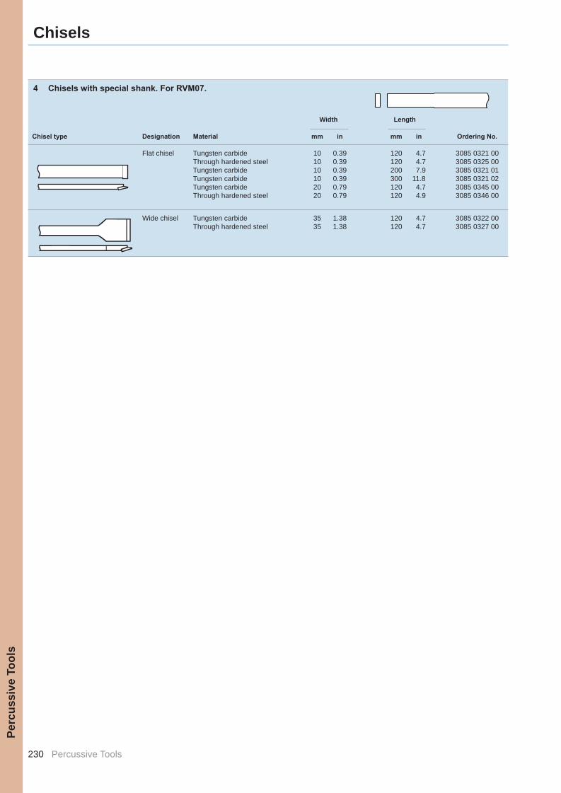
Perc
ussi
ve T
ools
230 Percussive Tools
Chisels
4 Chisels with special shank. For RVM07.
Width Length
Chisel type Designation Material mm in mm in Ordering No.
Flat chisel Tungsten carbide 10 0.39 120 4.7 3085 0321 00 Through hardened steel 10 0.39 120 4.7 3085 0325 00 Tungsten carbide 10 0.39 200 7.9 3085 0321 01 Tungsten carbide 10 0.39 300 11.8 3085 0321 02 Tungsten carbide 20 0.79 120 4.7 3085 0345 00 Through hardened steel 20 0.79 120 4.9 3085 0346 00
Wide chisel Tungsten carbide 35 1.38 120 4.7 3085 0322 00 Through hardened steel 35 1.38 120 4.7 3085 0327 00
Am_Percussive.indd 230 2012-02-07 13:34:40

Drills
Contents PageIntroduction ........................................ 232Pistol grip drills .................................. 234Straight drills ...................................... 238Angle drills ......................................... 240Micro stop drills.................................. 244Tappers .............................................. 246Screw‑feed drills ................................ 248Positive feed drills.............................. 249

Dril
ls
232 Drills
Reliable, productive and comfortable to work with
Introduction – Drills
The handheld drills in Atlas Copco’s wide range are of the highest quality and built to provide consistent reliability and performance in a wide range of applications. Their ad-vanced ergonomic designs make your job easier, safer and more efficient.
From the time our first drill was produced in 1901, Atlas Copco has demonstrated a genuine understanding of customer needs. Our drills have evolved to meet changing customer demands over the years. Whatever the job, Atlas Copco has a drill to match your exact require-ments.
Reliable When you pick up an Atlas Copco drill, you can be confident that it will do the job over and over again.
Powerfully productive Despite their compact designs, our drills consistently deliver all the power you need. Their high power-to-weight ratio ensures maximum material removal in the shortest possible time.
Ergonomic Thanks to 50 years of focusing on er-gonomics, Atlas Copco drills fit comfor-tably in your hand. Grips are anatomi-cally shaped to keep your arm and wrist straight, reducing the risk of injury during long-term use. The light weight and per-fect balance of each drill enables you to guide it smoothly and easily. Low noise and vibration levels make the tools com-fortable to work with all day long.
Durable, low maintenance The rugged, lubrication-free designs of our drills can withstand the toughest in-dustrial situations and go on working day in, day out. Maintenance requirements are low.
Quality throughout the tools’ life-cycle Atlas Copco stands for quality, from the manufacture of critical drill components, through production and sales, to service and support throughout the tools’ long life-cycle.
Am_Drills.indd 232 2012-02-07 13:53:26

Dril
ls
Drills 233
Chuck guardPrevents damage and gives good support
Wing designBetter grip = allows two different grips and higher feed force
Sensitive trigger Good throttling capability = precise and high quality holesReduces risk of “trigger finger” syndrome
Adjustable air exhaust, 360°= prevents cool air from affecting the operator
Correct angle:Reduce wrist loadHigher feed force =higher productivityReduce injuries
Soft grip:Comfortable temperature, not too coolGood grip, no risk of slipping
Drills
The speed for a specific drilling operation should be chosen on the basis of the material in the workpiece and the diameter of the hole. In the selection guide, you will find proposals for suitable free speeds for selection of the correct tool. Use the information below as a guide only. Many variables contribute to the optimal speed choice for a specific application.
Keyed chuck as standard and self tightening chuck as accessory
Rigid aluminum housing
High performance vane motor
Trim valve for adjusting the rpm
A suspen-sion yoke is included and attached here
Adjustable air exhaust
End stops at both ends of the handle
Chuck guard
Santopren “softgrip” material for insulation and good grip
Long lever as standard, safety lever as accessory
LBB 16 features LBB 16S features
a Remember that, if the speed is too low the cycle time increases.
Selection Guide
Cutting speeda sfpm Material
rpm
300
400
500
600
700
800
1000
1200
1300
1500
1700
1900
2200
2400
2600
2900
3000
3300
3700
3800
4500
5500
6000
6400
6500
2000
0
2300
0
2600
0
15Tita-nium
Alloy Steel
Dril
l dim
ensi
on /
in
3/16 5/32 1/8 1/8 1/16 1/16 1/16 1/32 1/32 1/32 1/32 1/32 1/32 1/32 1/32 1/32 1/3230 7/16 5/16 1/4 3/16 3/16 5/32 1/8 1/8 1/16 1/16 1/16 1/16 1/32 1/32 1/32 1/32 1/32 1/32 1/32 1/32 1/32 1/32 1/3250 Cast iron
1/2 3/8 5/16 1/4 1/4 3/16 5/32 5/32 1/8 1/8 1/8 1/16 1/16 1/16 1/16 1/16 1/32 1/32 1/32 1/32 1/32 1/32 1/32 1/3265
Mild steel5/8 1/2 7/16 3/8 5/16 1/4 3/16 3/16 5/32 5/32 1/8 1/8 1/8 1/16 1/16 1/16 1/16 1/16 1/16 1/32 1/32 1/32 1/32 1/32
80 1/2 7/16 3/8 5/16 1/4 1/4 3/16 3/16 5/32 5/32 1/8 1/8 1/8 1/8 1/16 1/16 1/16 1/16 1/32 1/32 1/32 1/32100
Hardplastics
3/8 5/16 1/4 1/4 1/4 3/16 5/32 5/32 5/32 1/8 1/8 1/8 1/8 1/8 1/16 1/16 1/16 1/32 1/32115 3/8 3/8 1/4 1/4 1/4 3/16 3/16 5/32 5/32 5/32 1/8 1/8 1/8 1/16 1/16 1/16 1/16 1/16 1/32130 3/8 5/16 1/4 1/4 1/4 3/16 3/16 5/32 5/32 5/32 1/8 1/8 1/8 1/16 1/16 1/16 1/16 1/32 1/32150 3/8 5/16 5/16 1/4 1/4 1/4 3/16 3/16 5/32 5/32 5/32 1/8 1/8 1/16 1/16 1/16 1/32 1/32 1/32165
CompositeAluminum andbronze
3/8 5/16 1/4 1/4 3/16 3/16 3/16 5/32 5/32 5/32 1/8 1/8 1/16 1/16 1/32 1/32 1/32180 3/8 3/8 5/16 1/4 1/4 1/4 3/16 3/16 3/16 5/32 1/8 1/8 1/8 1/8 1/32 1/32 1/32200 7/16 3/8 3/8 1/4 1/4 1/4 1/4 3/16 3/16 5/32 1/8 1/8 1/8 1/8 1/32 1/32 1/32215 1/2 3/8 5/16 1/4 1/4 1/4 3/16 3/16 5/32 1/8 1/8 1/8 1/32 1/32 1/32230 1/2 3/8 5/16 1/4 1/4 1/4 3/16 5/32 5/32 1/8 1/8 1/32 1/32 1/32245 9/16 1/4 1/4 1/4 3/16 5/32 5/32 5/32 5/32 1/32 1/32 1/32260
Woodandboard
9/16 5/16 1/4 1/4 3/16 5/32 5/32 5/32 1/32 1/32 1/32280 5/8 1/4 1/4 3/16 3/16 5/32 5/32 1/32 1/32 1/32295 5/16 1/4 3/16 5/32 5/32 1/32 1/32 1/32310 5/16 1/4 3/16 3/16 3/16 1/16 1/32 1/32330 3/8 1/4 3/16 3/16 3/16 1/16 1/32 1/32345 3/8 1/4 1/4 3/16 3/16 1/16 1/32 1/32360 3/8 5/16 1/4 3/16 3/16 1/16 1/16 1/32375 3/8 1/4 1/4 1/4 1/16 1/16 1/32395 1/4 1/4 1/4 1/16 1/16 1/32410 1/4 1/4 1/4 1/16 1/16 1/16425 1/4 1/4 1/4 1/16 1/16 1/16440 1/4 1/16 1/16 1/16460 1/4 1/16 1/16 1/16475 5/16 1/16 1/16 1/16500 5/16 1/16 1/16 1/16
Am_Drills.indd 233 2012-02-07 13:53:34
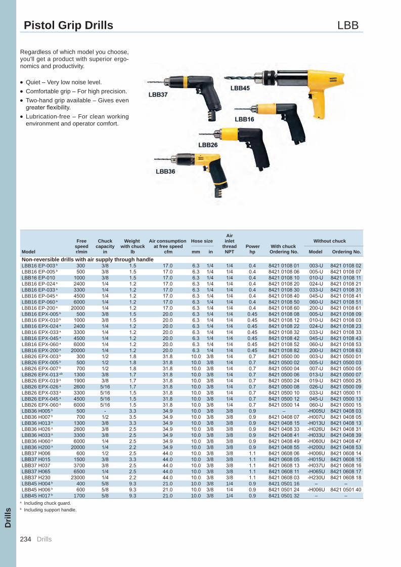
Dril
ls
234 Drills
Air Free Chuck Weight Air consumption Hose size inlet Without chuck speed capacity with chuck at free speed thread Power With chuckModel r/min in lb cfm mm in NPT hp Ordering No. Model Ordering No.Non-reversible drills with air supply through handle LBB16 EP-003 b 300 3/8 1.5 17.0 6.3 1/4 1/4 0.4 8421 0108 01 003‑U 8421 0108 02LBB16 EP-005 b 500 3/8 1.5 17.0 6.3 1/4 1/4 0.4 8421 0108 06 005‑U 8421 0108 07LBB16 EP‑010 1000 3/8 1.5 17.0 6.3 1/4 1/4 0.4 8421 0108 10 010‑U 8421 0108 11LBB16 EP-024 a 2400 1/4 1.2 17.0 6.3 1/4 1/4 0.4 8421 0108 20 024‑U 8421 0108 21LBB16 EP-033 a 3300 1/4 1.2 17.0 6.3 1/4 1/4 0.4 8421 0108 30 033‑U 8421 0108 31LBB16 EP-045 a 4500 1/4 1.2 17.0 6.3 1/4 1/4 0.4 8421 0108 40 045‑U 8421 0108 41LBB16 EP-060 a 6000 1/4 1.2 17.0 6.3 1/4 1/4 0.4 8421 0108 50 060‑U 8421 0108 51LBB16 EP-200 a 20000 1/4 1.2 17.0 6.3 1/4 1/4 0.4 8421 0108 60 200‑U 8421 0108 61LBB16 EPX-005 b 500 3/8 1.5 20.0 6.3 1/4 1/4 0.45 8421 0108 08 005‑U 8421 0108 09LBB16 EPX-010 b 1000 3/8 1.5 20.0 6.3 1/4 1/4 0.45 8421 0108 12 010‑U 8421 0108 03LBB16 EPX-024 a 2400 1/4 1.2 20.0 6.3 1/4 1/4 0.45 8421 0108 22 024‑U 8421 0108 23LBB16 EPX-033 a 3300 1/4 1.2 20.0 6.3 1/4 1/4 0.45 8421 0108 32 033‑U 8421 0108 33LBB16 EPX-045 a 4500 1/4 1.2 20.0 6.3 1/4 1/4 0.45 8421 0108 42 045‑U 8421 0108 43LBB16 EPX-060 a 6000 1/4 1.2 20.0 6.3 1/4 1/4 0.45 8421 0108 52 060‑U 8421 0108 53LBB16 EPX-200 a 20000 1/4 1.2 20.0 6.3 1/4 1/4 0.45 8421 0108 82 200‑U 8421 0108 63LBB26 EPX-003 b 300 1/2 1.8 31.8 10.0 3/8 1/4 0.7 8421 0500 00 003‑U 8421 0500 01LBB26 EPX-005 b 500 1/2 1.8 31.8 10.0 3/8 1/4 0.7 8421 0500 02 005‑U 8421 0500 03LBB26 EPX-007 b 700 1/2 1.8 31.8 10.0 3/8 1/4 0.7 8421 0500 04 007‑U 8421 0500 05LBB26 EPX-013 ab 1300 3/8 1.7 31.8 10.0 3/8 1/4 0.7 8421 0500 06 013‑U 8421 0500 07LBB26 EPX-019 a 1900 3/8 1.7 31.8 10.0 3/8 1/4 0.7 8421 0500 24 019‑U 8421 0500 25LBB26 EPX-026 a 2600 5/16 1.7 31.8 10.0 3/8 1/4 0.7 8421 0500 08 026‑U 8421 0500 09LBB26 EPX-033 a 3300 5/16 1.5 31.8 10.0 3/8 1/4 0.7 8421 0500 10 033‑U 8421 0500 11LBB26 EPX-045 a 4500 5/16 1.5 31.8 10.0 3/8 1/4 0.7 8421 0500 12 045‑U 8421 0500 13LBB26 EPX-060 a 6000 5/16 1.5 31.8 10.0 3/8 1/4 0.7 8421 0500 14 060‑U 8421 0500 15LBB36 H005 b 500 ‑ 3.3 34.9 10.0 3/8 3/8 0.9 – ‑H005U 8421 0408 03LBB36 H007 b 700 1/2 3.5 34.9 10.0 3/8 3/8 0.9 8421 0408 07 ‑H007U 8421 0408 05LBB36 H013 a 1300 3/8 3.3 34.9 10.0 3/8 3/8 0.9 8421 0408 15 ‑H013U 8421 0408 13LBB36 H026 a 2600 3/8 2.5 34.9 10.0 3/8 3/8 0.9 8421 0408 33 ‑H026U 8421 0408 31LBB36 H033 a 3300 3/8 2.5 34.9 10.0 3/8 3/8 0.9 8421 0408 41 ‑H033U 8421 0408 39LBB36 H060 a 6000 1/4 2.5 34.9 10.0 3/8 3/8 0.9 8421 0408 49 ‑H060U 8421 0408 47LBB36 H200 a 20000 1/4 2.2 34.9 10.0 3/8 3/8 0.9 8421 0408 55 ‑H200U 8421 0408 53LBB37 H006 600 1/2 2.5 44.0 10.0 3/8 3/8 1.1 8421 0608 06 ‑H006U 8421 0608 14LBB37 H015 1500 3/8 3.3 44.0 10.0 3/8 3/8 1.1 8421 0608 05 ‑H015U 8421 0608 15LBB37 H037 3700 3/8 2.5 44.0 10.0 3/8 3/8 1.1 8421 0608 13 ‑H037U 8421 0608 16LBB37 H065 6500 1/4 2.5 44.0 10.0 3/8 3/8 1.1 8421 0608 11 ‑H065U 8421 0608 17LBB37 H230 23000 1/4 2.2 44.0 10.0 3/8 3/8 1.1 8421 0608 03 ‑H230U 8421 0608 18LBB45 H004 b 400 5/8 9.3 21.0 10.0 3/8 1/4 0.9 8421 0501 16 – –LBB45 H006 b 600 5/8 9.3 21.0 10.0 3/8 1/4 0.9 8421 0501 24 ‑H006U 8421 0501 40LBB45 H017 b 1700 5/8 9.3 21.0 10.0 3/8 1/4 0.9 8421 0501 32 – –
Regardless of which model you choose, you'll get a product with superior ergo-nomics and productivity.
l Quiet – Very low noise level.l Comfortable grip – For high precision.l Two-hand grip available – Gives even
greater fl exibility. l Lubrication-free – For clean working
environment and operator comfort.
Pistol Grip Drills LBB
a Including chuck guard.b Including support handle.
Am_Drills.indd 234 2012-02-07 13:53:35
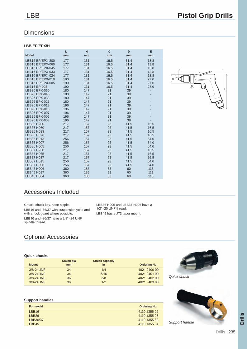
Dril
ls
Drills 235
CD
L
HE
Support handle
Quick chuck
Optional Accessories
Accessories Included
LBB Pistol Grip Drills
Chuck, chuck key, hose nipple.LBB16 and -36/37 with suspension yoke and with chuck guard where possible.LBB16 and ‑36/37 have a 3/8" ‑24 UNF spindle thread.
Support handlesFor model Ordering No.
LBB16 4110 1355 92LBB26 4110 1355 95LBB36/37 4110 1355 82LBB45 4110 1355 84
Quick chucks Chuck dia Chuck capacityMount mm in Ordering No.
3/8‑24UNF 34 1/4 4021 0400 003/8‑24UNF 34 5/16 4021 0401 003/8‑24UNF 36 3/8 4021 0402 003/8‑24UNF 36 1/2 4021 0403 00
Dimensions
L H C D EModel mm mm mm mm mm
LBB16 EP/EPX-200 177 131 16.5 31.4 13.8LBB16 EP/EPX-060 177 131 16.5 31.4 13.8LBB16 EP/EPX-045 177 131 16.5 31.4 13.8LBB16 EP/EPX-033 177 131 16.5 31.4 13.8LBB16 EP/EPX-024 177 131 16.5 31.4 13.8LBB16 EP/EPX-010 190 131 16.5 31.4 27.0LBB16 EP/EPX-005 190 131 16.5 31.4 27.0LBB16 EP-003 190 131 16.5 31.4 27.0LBB26 EPX-060 180 147 21 39 -LBB26 EPX-045 180 147 21 39 -LBB26 EPX-033 180 147 21 39 -LBB26 EPX-026 180 147 21 39 -LBB26 EPX-019 196 147 21 39 -LBB26 EPX-013 196 147 21 39 -LBB26 EPX-007 196 147 21 39 -LBB26 EPX-005 196 147 21 39 -LBB26 EPX-003 196 147 21 39 -LBB36 H200 217 157 23 41.5 16.5LBB36 H060 217 157 23 41.5 16.5LBB36 H033 217 157 23 41.5 16.5LBB36 H026 217 157 23 41.5 16.5LBB36 H013 256 157 23 41.5 64.0LBB36 H007 256 157 23 41.5 64.0LBB36 H005 256 157 23 41.5 64.0LBB37 H230 217 157 23 41.5 16.5LBB37 H065 217 157 23 41.5 16.5LBB37 H037 217 157 23 41.5 16.5LBB37 H015 256 157 23 41.5 64.0LBB37 H006 256 157 23 41.5 64.0LBB45 H006 360 185 33 60 113LBB45 H017 360 185 33 60 113LBB45 H004 360 185 33 60 113
LBB EP/EPX/H
LBB36 H005 and LBB37 H006 have a 1/2" ‑20 UNF thread.LBB45 has a JT3 taper mount.
Am_Drills.indd 235 2012-02-07 13:53:38

Dril
ls
236 Drills
Flex connect
Spot suction attachment
a Spare part, nose piece kit, Ordering No. 4110 1700 90.Other standard sizes of front nozzle available.
Collet chuck and collets
Capacity
Designation mm in Ordering No.
Collet 3 4150 0081 00 6 4150 0075 00 8 5/16 4150 0074 00 1/8 4150 0082 00 5/32 4150 0648 00 3/16 4150 0649 00 1/4 4150 0076 00Collet holder 4110 0844 90Collet nut 4150 0760 00
Collet chuck and collets
Spot suction attachment
Power feed arm for extra feed force – LBB36 H005 and LBB37 H006 Ordering No.
Adapter piece (SR295), lever arm (SR201), chain (SR202) 4110 1416 80and No. 2 Morse socket (SR206) Two extension pieces (SR204-1 and SR204-2), 370 and 750 mm long 4110 1417 80No. 2 Morse socket 4110 1416 01
Power feed arm
Hose size Spot suction kit a Hose kitFor model in Ordering No. Ordering No.
LBB16 1 1/4 4110 1715 80 4112 1227 00LBB26 1 1/4 4110 1715 84 4112 1227 00LBB36/37 1 1/4 4110 1716 80 4112 1227 00
Flex connect
For model Ordering No.
LBB16 4110 1601 80
Silencer set
Silencer setsFor model Ordering No.
LBB45 External silencer 4112 0863 80
Accessories Pistol Grip Drills
Optional Accessories
Am_Drills.indd 236 2012-02-07 13:53:45
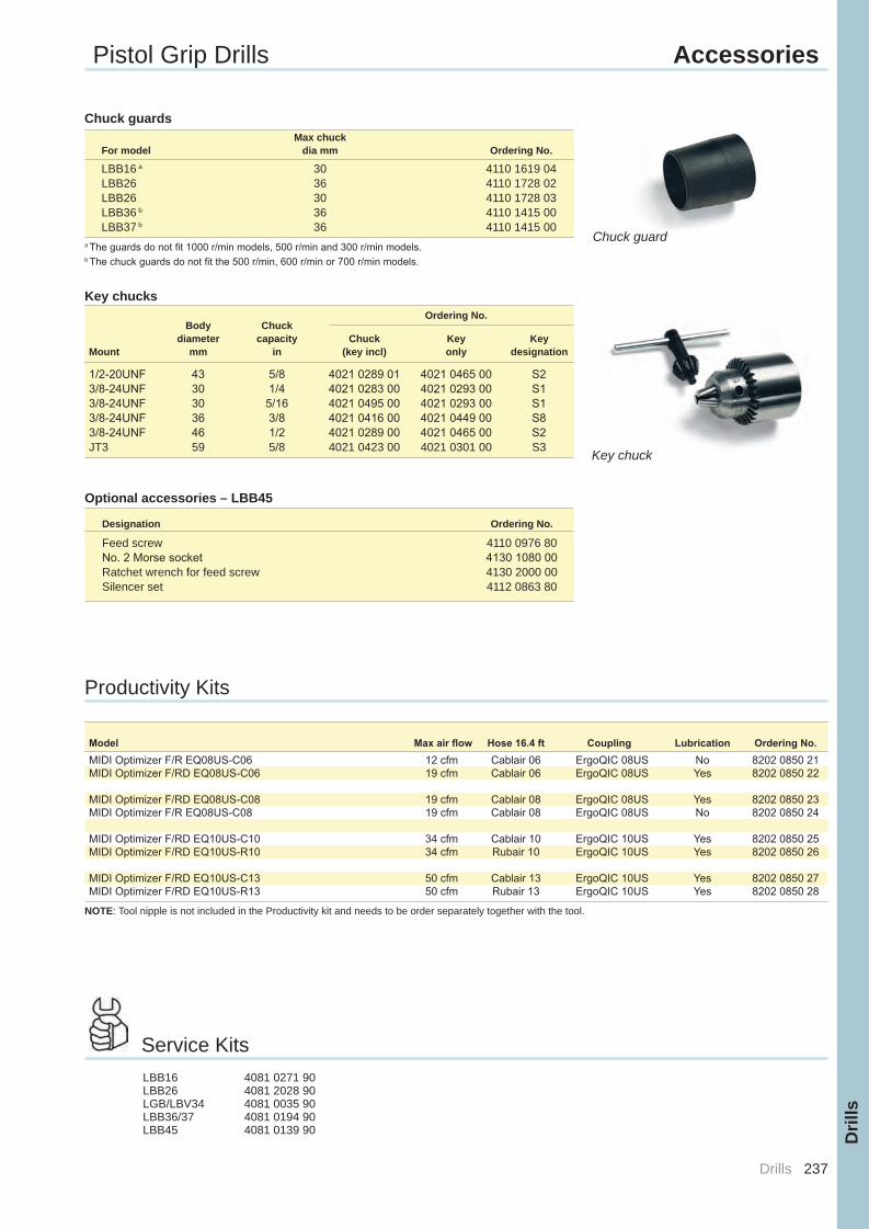
Dril
ls
Drills 237
Designation Ordering No.
Feed screw 4110 0976 80No. 2 Morse socket 4130 1080 00Ratchet wrench for feed screw 4130 2000 00Silencer set 4112 0863 80
a The guards do not fit 1000 r/min models, 500 r/min and 300 r/min models.b The chuck guards do not fit the 500 r/min, 600 r/min or 700 r/min models.
Chuck guard
Max chuckFor model dia mm Ordering No.
LBB16 a 30 4110 1619 04LBB26 36 4110 1728 02LBB26 30 4110 1728 03LBB36 b 36 4110 1415 00LBB37 b 36 4110 1415 00
Chuck guards
Key chucks
Key chuck
Ordering No. Body Chuck diameter capacity Chuck Key KeyMount mm in (key incl) only designation
1/2‑20UNF 43 5/8 4021 0289 01 4021 0465 00 S23/8‑24UNF 30 1/4 4021 0283 00 4021 0293 00 S13/8‑24UNF 30 5/16 4021 0495 00 4021 0293 00 S13/8‑24UNF 36 3/8 4021 0416 00 4021 0449 00 S83/8‑24UNF 46 1/2 4021 0289 00 4021 0465 00 S2JT3 59 5/8 4021 0423 00 4021 0301 00 S3
Pistol Grip Drills Accessories
Service Kits LBB16 4081 0271 90 LBB26 4081 2028 90 LGB/LBV34 4081 0035 90 LBB36/37 4081 0194 90 LBB45 4081 0139 90
Productivity Kits
Model Max air flow Hose 16.4 ft Coupling Lubrication Ordering No.MIDI Optimizer F/R EQ08US‑C06 12 cfm Cablair 06 ErgoQIC 08US No 8202 0850 21MIDI Optimizer F/RD EQ08US‑C06 19 cfm Cablair 06 ErgoQIC 08US Yes 8202 0850 22
MIDI Optimizer F/RD EQ08US‑C08 19 cfm Cablair 08 ErgoQIC 08US Yes 8202 0850 23MIDI Optimizer F/R EQ08US‑C08 19 cfm Cablair 08 ErgoQIC 08US No 8202 0850 24
MIDI Optimizer F/RD EQ10US‑C10 34 cfm Cablair 10 ErgoQIC 10US Yes 8202 0850 25MIDI Optimizer F/RD EQ10US‑R10 34 cfm Rubair 10 ErgoQIC 10US Yes 8202 0850 26
MIDI Optimizer F/RD EQ10US‑C13 50 cfm Cablair 13 ErgoQIC 10US Yes 8202 0850 27MIDI Optimizer F/RD EQ10US‑R13 50 cfm Rubair 13 ErgoQIC 10US Yes 8202 0850 28
Optional accessories – LBB45
NOTE: Tool nipple is not included in the Productivity kit and needs to be order separately together with the tool.
Am_Drills.indd 237 2012-02-07 13:53:47
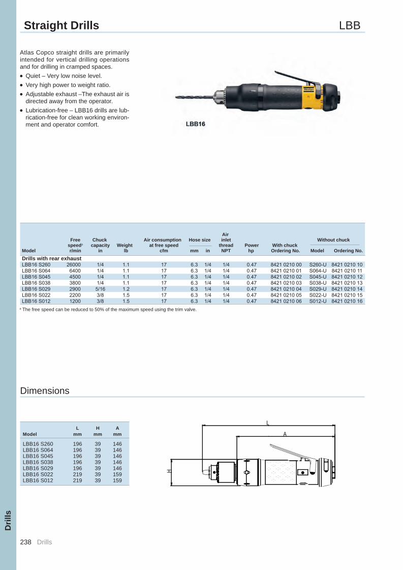
Dril
ls
238 Drills
L
H
A
DC
H
L
E
Straight Drills LBB
Air Free Chuck Air consumption Hose size inlet Without chuck speeda capacity Weight at free speed thread Power With chuckModel r/min in lb cfm mm in NPT hp Ordering No. Model Ordering No.Drills with rear exhaustLBB16 S260 26000 1/4 1.1 17 6.3 1/4 1/4 0.47 8421 0210 00 S260‑U 8421 0210 10LBB16 S064 6400 1/4 1.1 17 6.3 1/4 1/4 0.47 8421 0210 01 S064‑U 8421 0210 11LBB16 S045 4500 1/4 1.1 17 6.3 1/4 1/4 0.47 8421 0210 02 S045‑U 8421 0210 12LBB16 S038 3800 1/4 1.1 17 6.3 1/4 1/4 0.47 8421 0210 03 S038‑U 8421 0210 13LBB16 S029 2900 5/16 1.2 17 6.3 1/4 1/4 0.47 8421 0210 04 S029‑U 8421 0210 14LBB16 S022 2200 3/8 1.5 17 6.3 1/4 1/4 0.47 8421 0210 05 S022‑U 8421 0210 15LBB16 S012 1200 3/8 1.5 17 6.3 1/4 1/4 0.47 8421 0210 06 S012‑U 8421 0210 16
a The free speed can be reduced to 50% of the maximum speed using the trim valve.
Dimensions
Atlas Copco straight drills are primarily intended for vertical drilling operations and for drilling in cramped spaces.l Quiet – Very low noise level.l Very high power to weight ratio.l Adjustable exhaust –The exhaust air is
directed away from the operator.l Lubrication-free – LBB16 drills are lub-
rication-free for clean working environ-ment and operator comfort.
L H AModel mm mm mm
LBB16 S260 196 39 146LBB16 S064 196 39 146LBB16 S045 196 39 146LBB16 S038 196 39 146LBB16 S029 196 39 146LBB16 S022 219 39 159LBB16 S012 219 39 159
Am_Drills.indd 238 2012-02-07 13:53:48
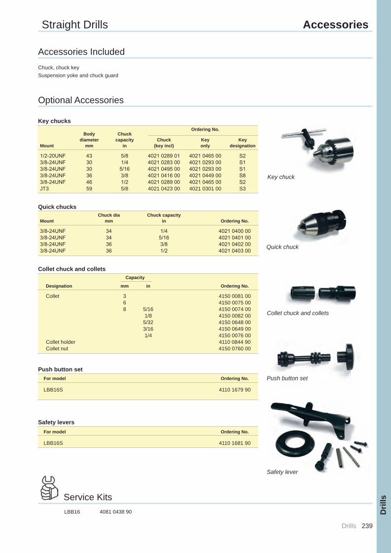
Dril
ls
Drills 239
Optional Accessories
Accessories IncludedChuck, chuck keySuspension yoke and chuck guard
Straight Drills Accessories
Key chuck
Ordering No. Body Chuck diameter capacity Chuck Key KeyMount mm in (key incl) only designation
1/2‑20UNF 43 5/8 4021 0289 01 4021 0465 00 S23/8‑24UNF 30 1/4 4021 0283 00 4021 0293 00 S13/8‑24UNF 30 5/16 4021 0495 00 4021 0293 00 S13/8‑24UNF 36 3/8 4021 0416 00 4021 0449 00 S83/8‑24UNF 46 1/2 4021 0289 00 4021 0465 00 S2JT3 59 5/8 4021 0423 00 4021 0301 00 S3
Key chucks
Quick chuck
Quick chucks Chuck dia Chuck capacityMount mm in Ordering No.
3/8‑24UNF 34 1/4 4021 0400 003/8‑24UNF 34 5/16 4021 0401 003/8‑24UNF 36 3/8 4021 0402 003/8‑24UNF 36 1/2 4021 0403 00
Collet chuck and collets Capacity
Designation mm in Ordering No.
Collet 3 4150 0081 00 6 4150 0075 00 8 5/16 4150 0074 00 1/8 4150 0082 00 5/32 4150 0648 00 3/16 4150 0649 00 1/4 4150 0076 00Collet holder 4110 0844 90Collet nut 4150 0760 00
Collet chuck and collets
Push button setFor model Ordering No.
LBB16S 4110 1679 90
Push button set
Safety leversFor model Ordering No.
LBB16S 4110 1681 90
Safety lever
Service Kits LBB16 4081 0438 90
Am_Drills.indd 239 2012-02-07 13:53:53
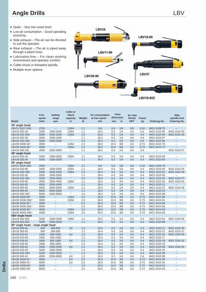
Dril
ls
240 Drills
l Quiet – Very low noise level.l Low air consumption – Good operating
economy.l Side exhaust – The air can be directed
to suit the operator.l Rear exhaust – The air is piped away
through a pliant hose.l Lubrication-free – For clean working
environment and operator comfort.l Collet chuck or threaded spindle.l Multiple lever options.
Collet or Free Setting chuck Air consumption Hose Air inlet With speed range capacity Weight at free speed dimension thread Power spindle lockModel r/min rpm in lb cfm mm in NPT hp Ordering No. Ordering No.30o angle head LBV11 S027-S30 2700 – 13/64 1.1 6.8 5.0 1/8 1/8 0.16 8421 0108 70 – LBV16 032-30 3200 1500-3200 13/64 1.1 18.4 6.3 1/4 1/4 0.4 8421 0110 05 8421 0110 30 LBV16 032-S30 3200 1500-3200 13/64 1.0 18.4 6.3 1/4 1/4 0.4 8421 0110 04 8421 0110 29 LBV16 032-32 3200 1500-3200 c 1.1 18.4 6.3 1/4 1/4 0.4 8421 0110 07 – LBV16 032-S32 3200 1500-3200 c 1.0 18.4 6.3 1/4 1/4 0.4 8421 0110 06 – LBV36 S030-30 e 3000 – 13/64 2.2 36.0 10.0 3/8 1/4 0.73 8421 0414 70 – LBV36 S045-30 e 4500 – 13/64 2.2 36.0 10.0 3/8 1/4 0.73 8421 0414 72 – LBV16 045-32L 4500 3200-4500 c 1.1 18.4 6.3 1/4 1/4 0.4 – 8421 0110 57 45o angle headLBV16 032-45 3200 1500-3200 13/64 1.1 18.4 6.3 1/4 1/4 0.4 8421 0110 59 – LBV16 032-46 3200 1500-3200 c 1.1 18.4 6.3 1/4 1/4 0.4 8421 0110 60 – 90o angle head LBV11 S025-S90 2500 – 13/64 1.1 6.8 5.0 1/8 1/8 0.16 8421 0109 79 – LBV16 032-90 3200 1500-3200 13/64 1.1 18.4 6.3 1/4 1/4 0.4 8421 0110 00 8421 0110 25 LBV16 032-S90 3200 1500-3200 13/64 1.0 18.4 6.3 1/4 1/4 0.4 8421 0110 01 8421 0110 26 LBV16 032-92 3200 1500-3200 c 1.1 18.4 6.3 1/4 1/4 0.4 8421 0110 03 – LBV16 032-S92 3200 1500-3200 c 1.0 18.4 6.3 1/4 1/4 0.4 8421 0110 02 8421 0110 27 LBV16 045-90 4500 3200-4500 13/64 1.1 18.4 6.3 1/4 1/4 0.4 8421 0110 20 8421 0110 44 LBV16 045-92 4500 3200-4500 c 1.1 18.4 6.3 1/4 1/4 0.4 8421 0110 21 – LBV16 055-90 5500 4500-5500 13/64 1.1 18.4 6.3 1/4 1/4 0.4 8421 0110 23 8421 0110 46 LBV16 055-92 5500 4500-5500 c 1.1 18.4 6.3 1/4 1/4 0.4 8421 0110 24 – LBV16 055-S92 5500 4500-5500 c 1.0 18.4 6.3 1/4 1/4 0.4 8421 0110 58 – LBV36 S030-90 e 3000 – 13/64 2.2 36.0 10.0 3/8 1/4 0.73 8421 0414 60 – LBV36 S030-S90 e 3000 – 13/64 2.0 36.0 10.0 3/8 1/4 0.73 8421 0414 61 – LBV36 S030-92 e 3000 – c 2.2 36.0 10.0 3/8 1/4 0.73 8421 0414 64 – LBV36 S030-S92 e 3000 – c 2.0 36.0 10.0 3/8 1/4 0.73 8421 0414 65 – LBV36 S045-90 e 4500 – 13/64 2.2 36.0 10.0 3/8 1/4 0.73 8421 0414 62 – LBV36 S045-S90 e 4500 – 13/64 2.0 36.0 10.0 3/8 1/4 0.73 8421 0414 63 – 360o angle head LBV16 032-90Z 3200 1500-3200 13/64 1.1 18.4 6.3 1/4 1/4 0.4 8421 0110 64 8421 0110 65 LBV16 032-92Z 3200 1500-3200 c 1.1 18.4 6.3 1/4 1/4 0.4 8421 0110 68 – 90o angle head – large angle headLBV16 005-91 500 200-500 1/4 1.2 18.4 6.3 1/4 1/4 0.4 8421 0110 11 8421 0110 36 LBV16 005-93 500 200-500 c 1.2 18.4 6.3 1/4 1/4 0.4 8421 0110 12 8421 0110 37 LBV16 010-91 1000 500-1000 1/4 1.2 18.4 6.3 1/4 1/4 0.4 8421 0110 16 8421 0110 40 LBV16 010-93 1000 500-1000 c 1.2 18.4 6.3 1/4 1/4 0.4 8421 0110 17 – LBV16 018-91 1800 800-1800 1/4 1.2 18.4 6.3 1/4 1/4 0.4 8421 0110 18 8421 0110 42 LBV16 018-93 1800 800-1800 c 1.2 18.4 6.3 1/4 1/4 0.4 8421 0110 19 – LBV16 032-91 3200 1500-3200 1/4 1.2 18.4 6.3 1/4 1/4 0.4 8421 0110 09 8421 0110 34 LBV16 032-93 3200 1500-3200 c 1.2 18.4 6.3 1/4 1/4 0.4 8421 0110 10 – LBV16 032-S93 3200 1500-3200 c 1.2 18.4 6.3 1/4 1/4 0.4 8421 0110 39 – LBV16 045-91 4500 3200-4500 1/4 1.2 18.4 6.3 1/4 1/4 0.4 8421 0110 38 – LBV36 S030-91 e 3000 – 1/4 2.2 36.0 10.0 3/8 1/4 0.73 8421 0414 50 – LBV36 S060-91 e 6000 – 1/4 2.2 36.0 10.0 3/8 1/4 0.73 8421 0414 51 – LBV36 S030-93 e 3000 – c 2.2 36.0 10.0 3/8 1/4 0.73 8421 0414 52 – LBV36 S060-93 e 6000 – c 2.2 36.0 10.0 3/8 1/4 0.73 8421 0414 53 –
Angle Drills LBV
Am_Drills.indd 240 2012-02-07 13:53:54

Dril
ls
Drills 241
36
10
110
10
110
41
9
71 ( - S90 )
111 ( - 90 )
30
30
71 ( - S91 )
111 ( - 91 )
9
103( - S32 )
143 ( - 32 )
9
103 ( - S30 )
143 ( - 30 )
9
39
31
98
34,5
39
9
98
30-type
32-type
90-type
92-type
90Z-type
92Z-type
91-type
93-type
Collet capacity up to 5 mm,standard 3 mm Collet capacity up to 6.6 mm,
standard 6 mm
Internal thread 1/4"-28
Internal thread 1/4"-28
Internal thread 1/4"-28
Internal thread 1/4"-28
Collet capacity up to 5 mm,standard 3 mm
Collet capacity up to 5 mm,standard 3 mm
Collet or Free Setting chuck Air consumption Hose Air inlet With speed range capacity Weight at free speed dimension thread Power spindle lockModel r/min rpm in lb cfm mm in NPT hp Ordering No. Ordering No.90o angle head – Key chuck modelsLBV16 018-11 1800 800-1800 1/4 a 1.7 18.4 6.3 1/4 1/4 0.4 8421 0110 22 – LBV34 S005 b 500 – 1/2 a 4.6 15.9 10.0 3/8 1/4 0.6 8421 0309 04 – LBV34 S010 b 1000 – 3/8 a 4.4 15.9 10.0 3/8 1/4 0.6 8421 0309 12 – LBV34 S040 b 4000 – 1/4 a 3.3 15.9 10.0 3/8 1/4 0.6 8421 0309 46 – 90o angle head – heavy-dutyLBV37 030 3000 – c 2.4 46 10.0 3/8 3/8 1.1 8421 0414 54 – LBV37 055 5500 – c 2.4 46 10.0 3/8 3/8 1.1 8421 0414 55 – LBV37 HD030 3000 – d 2.4 46 10.0 3/8 3/8 1.1 8421 0414 56 – LBV37 HD055 5500 – d 2.4 46 10.0 3/8 3/8 1.1 8421 0414 57 –
a Spindle thread, male 3/8"‑24 UNF.b Side exhaust.
Dimensions
c Internal thread 1/4"-28.d Internal thread 5/16".e Short lever as standard.
LBV Angle Drills
Am_Drills.indd 241 2012-02-07 13:53:55
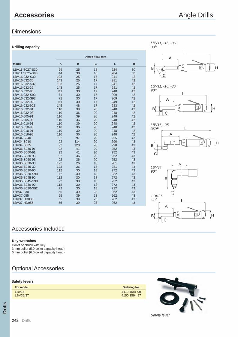
Dril
ls
242 Drills
H
LA
B
C
BC
AL
H
A
B
C
L
H
C
L
HB
A
CHB
A
L
HB
AL
C
C
A
B
32
BC
AL
H
Drilling capacity
Angle head mm Model A B C L H
LBV11 S027-S30 59 25 18 224 30LBV11 S025-S90 44 30 18 204 30LBV16 032-S30 103 25 17 241 42LBV16 032-30 143 25 17 281 42LBV16 032-S32 103 25 17 241 42LBV16 032-32 143 25 17 281 42LBV16 032-90 111 30 17 248 42LBV16 032-S90 71 30 17 209 42LBV16 032-S92 71 30 17 209 42LBV16 032-92 111 30 17 249 42LBV16 032-90Z 145 48 17 283 42LBV16 032-91 110 39 20 248 42LBV16 032-93 110 36 20 248 42LBV16 005-91 110 39 20 248 42LBV16 005-93 110 36 20 248 42LBV16 010-91 110 39 20 248 42LBV16 010-93 110 36 20 248 42LBV16 018-91 110 39 20 248 42LBV16 018-93 110 36 20 248 42LBV34 S040 92 97 20 255 43LBV34 S010 92 114 20 290 43LBV34 S005 92 120 20 290 43LBV36 S030-91 92 41 20 252 43LBV36 S060-91 92 41 20 252 43LBV36 S030-93 92 36 20 252 43LBV36 S060-93 92 36 20 252 43LBV36 S030-30 122 26 18 281 43LBV36 S045-30 122 26 18 281 43LBV36 S030-90 112 30 18 272 43LBV36 S030-S90 72 30 18 232 43LBV36 S045-90 112 30 18 272 43LBV36 S045-S90 72 30 18 232 43LBV36 S030-92 112 30 18 272 43LBV36 S030-S92 72 30 18 232 43LBV37 030 55 39 23 262 43LBV37 055 55 39 23 262 43LBV37 HD030 55 39 23 262 43LBV37 HD055 55 39 23 262 43
Safety leversFor model Ordering No.LBV16 4110 1681 90LBV36/37 4150 1594 97
Safety lever
Optional Accessories
Accessories Included
Accessories Angle Drills
Key wrenchesCollet or chuck with key3 mm collet (5.0 collet capacity head)6 mm collet (6.6 collet capacity head)
Dimensions
LBV11, -16, -36 30o
LBV11, -16, -36 90o
LBV16, -25 360o
LBV34 90o
LBV37 90o
Am_Drills.indd 242 2012-02-07 13:53:57
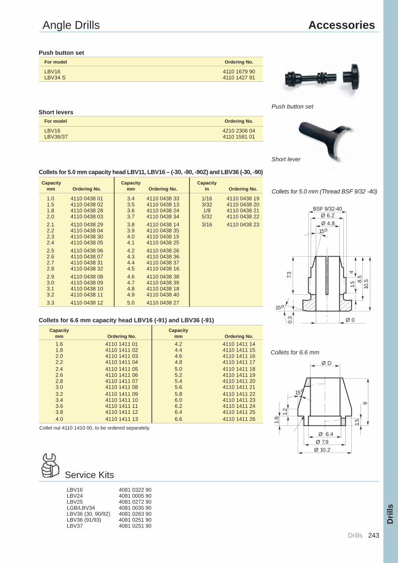
Dril
ls
Drills 243
1.5 8.
510
.5
4
7.3
BSF 9/32-40Ø 6.2
Ø 4.8
Ø 0
15o
0.3
15o
1.5
9Ø D
15o
Ø 10.2
Ø 7.9
Ø 6.4
1.8
1.2
Collets for 5.0 mm capacity head LBV11, LBV16 – (-30, -90, -90Z) and LBV36 (-30, -90)
Capacity Capacity Capacitymm Ordering No. mm Ordering No. in Ordering No.
1.0 4110 0438 01 3.4 4110 0438 33 1/16 4110 0438 191.5 4110 0438 02 3.5 4110 0438 13 3/32 4110 0438 201.8 4110 0438 28 3.6 4110 0438 24 1/8 4110 0438 212.0 4110 0438 03 3.7 4110 0438 34 5/32 4110 0438 222.1 4110 0438 29 3.8 4110 0438 14 3/16 4110 0438 232.2 4110 0438 04 3.9 4110 0438 35 2.3 4110 0438 30 4.0 4110 0438 15 2.4 4110 0438 05 4.1 4110 0438 25 2.5 4110 0438 06 4.2 4110 0438 26 2.6 4110 0438 07 4.3 4110 0438 36 2.7 4110 0438 31 4.4 4110 0438 37 2.8 4110 0438 32 4.5 4110 0438 16 2.9 4110 0438 08 4.6 4110 0438 38 3.0 4110 0438 09 4.7 4110 0438 39 3.1 4110 0438 10 4.8 4110 0438 18 3.2 4110 0438 11 4.9 4110 0438 40 3.3 4110 0438 12 5.0 4110 0438 27
Collets for 6.6 mm
Collets for 6.6 mm capacity head LBV16 (-91) and LBV36 (-91) Capacity Capacity mm Ordering No. mm Ordering No. 1.6 4110 1411 01 4.2 4110 1411 14 1.8 4110 1411 02 4.4 4110 1411 15 2.0 4110 1411 03 4.6 4110 1411 16 2.2 4110 1411 04 4.8 4110 1411 17 2.4 4110 1411 05 5.0 4110 1411 18 2.6 4110 1411 06 5.2 4110 1411 19 2.8 4110 1411 07 5.4 4110 1411 20 3.0 4110 1411 08 5.6 4110 1411 21 3.2 4110 1411 09 5.8 4110 1411 22 3.4 4110 1411 10 6.0 4110 1411 23 3.6 4110 1411 11 6.2 4110 1411 24 3.8 4110 1411 12 6.4 4110 1411 25 4.0 4110 1411 13 6.6 4110 1411 26
Collet nut 4110 1410 00, to be ordered separately.
Push button setFor model Ordering No.
LBV16 4110 1679 90LBV34 S 4110 1427 91
Push button setShort levers
For model Ordering No.
LBV16 4210 2306 04LBV36/37 4110 1581 01
Short lever
Service Kits LBV16 4081 0322 90 LBV24 4081 0005 90 LBV25 4081 0272 90 LGB/LBV34 4081 0035 90 LBV36 (30, 90/92) 4081 0263 90 LBV36 (91/93) 4081 0251 90 LBV37 4081 0251 90
Angle Drills Accessories
Collets for 5.0 mm (Thread BSF 9/32 -40)
Am_Drills.indd 243 2012-02-07 13:53:59
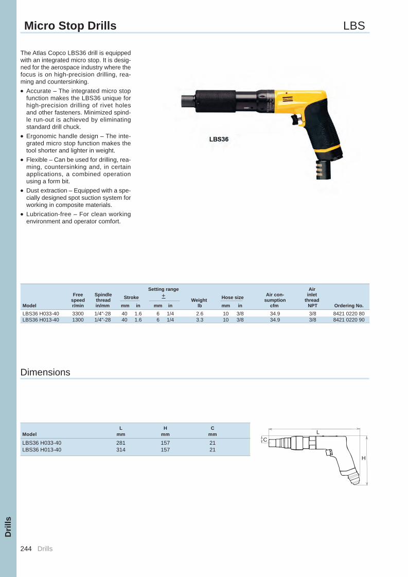
Dril
ls
244 Drills
C
H
L
Setting range Air Free Spindle Stroke + Hose size Air con- inlet speed thread Weight sumption threadModel r/min in/mm mm in mm in lb mm in cfm NPT Ordering No.LBS36 H033-40 3300 1/4"-28 40 1.6 6 1/4 2.6 10 3/8 34.9 3/8 8421 0220 80LBS36 H013-40 1300 1/4"-28 40 1.6 6 1/4 3.3 10 3/8 34.9 3/8 8421 0220 90
Micro Stop Drills LBS
Dimensions
The Atlas Copco LBS36 drill is equipped with an integrated micro stop. It is desig-ned for the aerospace industry where the focus is on high-precision drilling, rea-ming and countersinking.l Accurate – The integrated micro stop
function makes the LBS36 unique for high-precision drilling of rivet holes and other fasteners. Minimized spind-le run-out is achieved by eliminating standard drill chuck.
l Ergonomic handle design – The inte-grated micro stop function makes the tool shorter and lighter in weight.
l Flexible – Can be used for drilling, rea-ming, countersinking and, in certain applications, a combined operation using a form bit.
l Dust extraction – Equipped with a spe-cially designed spot suction system for working in composite materials.
l Lubrication-free – For clean working environment and operator comfort.
L H CModel mm mm mm
LBS36 H033-40 281 157 21LBS36 H013-40 314 157 21
Am_Drills.indd 244 2012-02-07 13:54:00
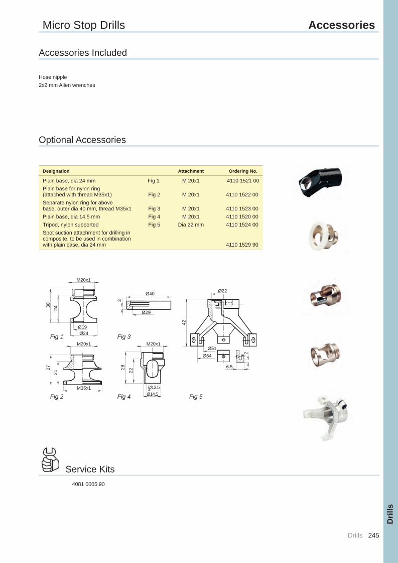
Dril
ls
Drills 245
Ø19Ø24
++
Ø64
6.5
2
28
22
Ø14.5
Ø12.5
M20x1M20x1
M35x1
21
27
M20x1
24
30
Ø40
Ø29
3
Ø22
42
Ø51
Hose nipple2x2 mm Allen wrenches
Designation Attachment Ordering No.
Plain base, dia 24 mm Fig 1 M 20x1 4110 1521 00Plain base for nylon ring(attached with thread M35x1) Fig 2 M 20x1 4110 1522 00Separate nylon ring for abovebase, outer dia 40 mm, thread M35x1 Fig 3 M 20x1 4110 1523 00Plain base, dia 14.5 mm Fig 4 M 20x1 4110 1520 00Tripod, nylon supported Fig 5 Dia 22 mm 4110 1524 00Spot suction attachment for drilling incomposite, to be used in combinationwith plain base, dia 24 mm 4110 1529 90
Micro Stop Drills Accessories
Service Kits 4081 0005 90
Optional Accessories
Accessories Included
Fig 1
Fig 2
Fig 3
Fig 4 Fig 5
Am_Drills.indd 245 2012-02-07 13:54:02
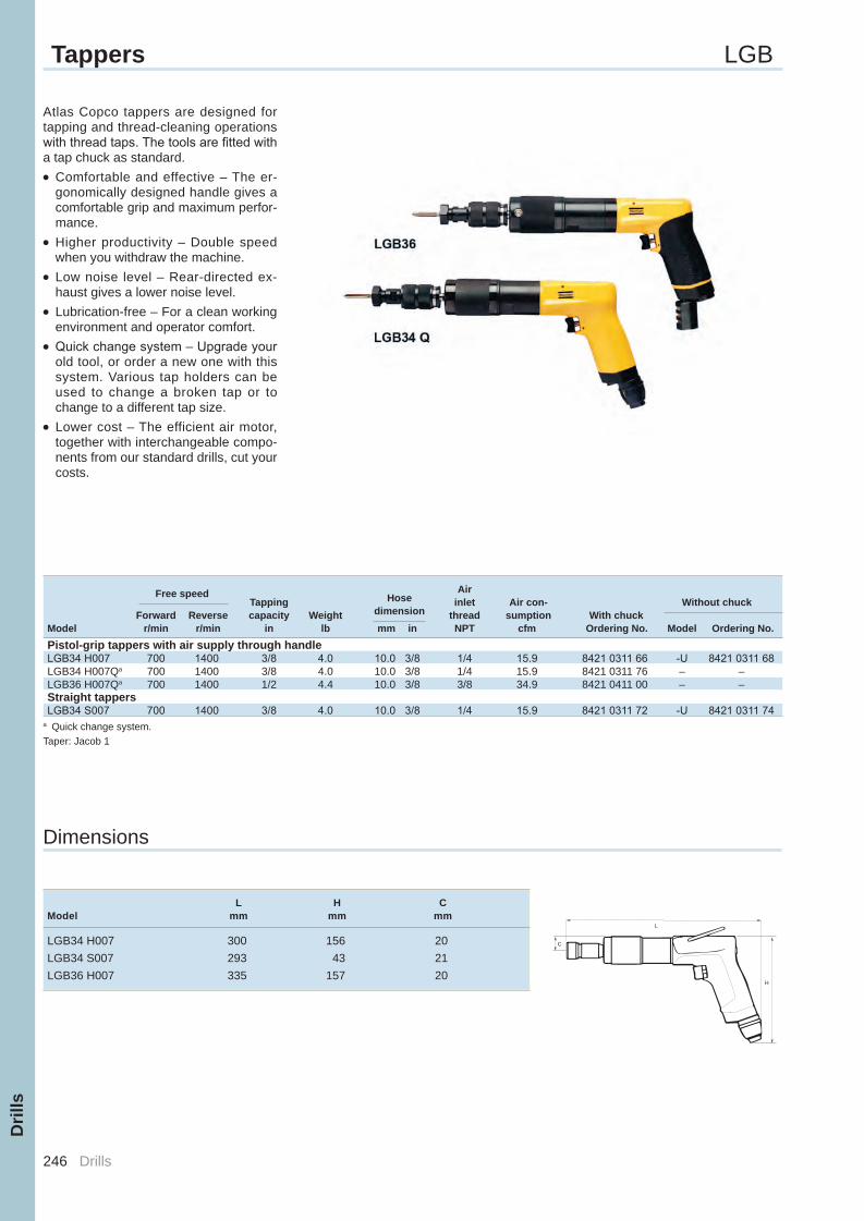
Dril
ls
246 Drills
C
L
H
Atlas Copco tappers are designed for tapping and thread-cleaning operations with thread taps. The tools are fi tted with a tap chuck as standard.l Comfortable and effective – The er-
gonomically designed handle gives a comfortable grip and maximum perfor-mance.
l Higher productivity – Double speed when you withdraw the machine.
l Low noise level – Rear-directed ex-haust gives a lower noise level.
l Lubrication-free – For a clean working environment and operator comfort.
l Quick change system – Upgrade your old tool, or order a new one with this system. Various tap holders can be used to change a broken tap or to change to a different tap size.
l Lower cost – The efficient air motor, together with interchangeable compo-nents from our standard drills, cut your costs.
Free speed Air Tapping Hose inlet Air con- Without chuck Forward Reverse capacity Weight dimension thread sumption With chuckModel r/min r/min in lb mm in NPT cfm Ordering No. Model Ordering No.Pistol-grip tappers with air supply through handleLGB34 H007 700 1400 3/8 4.0 10.0 3/8 1/4 15.9 8421 0311 66 ‑U 8421 0311 68LGB34 H007Qa 700 1400 3/8 4.0 10.0 3/8 1/4 15.9 8421 0311 76 – – LGB36 H007Qa 700 1400 1/2 4.4 10.0 3/8 3/8 34.9 8421 0411 00 – – Straight tappers LGB34 S007 700 1400 3/8 4.0 10.0 3/8 1/4 15.9 8421 0311 72 ‑U 8421 0311 74
a Quick change system.Taper: Jacob 1
L H CModel mm mm mm
LGB34 H007 300 156 20LGB34 S007 293 43 21LGB36 H007 335 157 20
Tappers LGB
Dimensions
Am_Drills.indd 246 2012-02-07 13:54:03
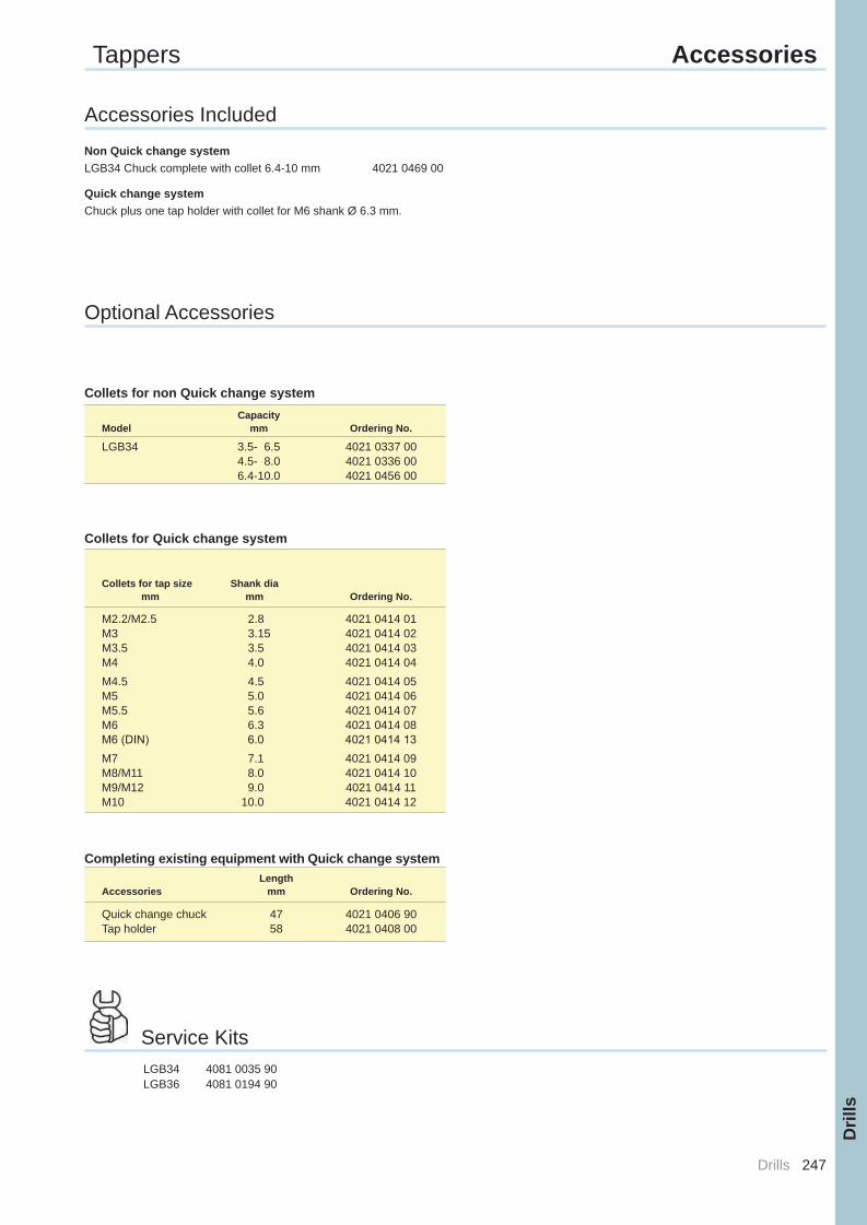
Dril
ls
Drills 247
Collets for non Quick change system CapacityModel mm Ordering No.
LGB34 3.5- 6.5 4021 0337 00 4.5- 8.0 4021 0336 00 6.4-10.0 4021 0456 00
Collets for Quick change system
Completing existing equipment with Quick change system LengthAccessories mm Ordering No.
Quick change chuck 47 4021 0406 90Tap holder 58 4021 0408 00
Tappers Accessories
Optional Accessories
Accessories IncludedNon Quick change systemLGB34 Chuck complete with collet 6.4-10 mm 4021 0469 00
Quick change systemChuck plus one tap holder with collet for M6 shank Ø 6.3 mm.
Collets for tap size Shank dia mm mm Ordering No.
M2.2/M2.5 2.8 4021 0414 01M3 3.15 4021 0414 02M3.5 3.5 4021 0414 03M4 4.0 4021 0414 04M4.5 4.5 4021 0414 05M5 5.0 4021 0414 06M5.5 5.6 4021 0414 07M6 6.3 4021 0414 08M6 (DIN) 6.0 4021 0414 13M7 7.1 4021 0414 09M8/M11 8.0 4021 0414 10M9/M12 9.0 4021 0414 11M10 10.0 4021 0414 12
Service Kits LGB34 4081 0035 90 LGB36 4081 0194 90
Am_Drills.indd 247 2012-02-07 13:54:03
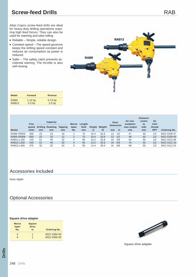
Dril
ls
248 Drills
Distance Capacity Hose Air con- centre Air Free Morse Length dimension sumption to inlet speed Drilling Reaming Tapping taper feed Height Weight max output side threadModel r/min mm mm mm No. mm in lb mm in cfm mm NPT Ordering No.RAB9 VR003 300 23 23 16 2 75 10.4 20.9 13 1/2 47 40 1/2 8421 5109 37RAB9 VR006 600 23 23 12 2 75 10.4 20.9 13 1/2 49 40 1/2 8421 5109 45RAB12 L150 140 51 40 32 4 90 15.2 32.8 16 5/8 64 50 1/2 8421 5112 08RAB12 L250 240 51 40 30 4 90 13.2 32.8 16 5/8 70 50 1/2 8421 5112 16RAB12 L450 475 32 32 24 3 90 13.4 28.4 16 5/8 68 50 1/2 8421 5112 24
Morse Square taper drive No. in Ordering No.
3 1 4021 0394 00 4 1 4021 0395 00
Model Forward Reverse
RAB9 1.14 hp 0.74 hpRAB12 2.0 hp 1.5 hp
Optional Accessories
Accessories Included
Square drive adapter
Screw-feed Drills RAB
Atlas Copco screw-feed drills are ideal for heavy-duty drilling operations requi-ring high feed forces. They can also be used for reaming and tube-rolling.l Reliable – Simple, reliable design.l Constant speed – The speed governor
keeps the drilling speed constant and reduces air consumption as power is reduced.
l Safer – The safety catch prevents ac-cidental starting. The throttle is also self-closing.
Hose nipple
Square drive adapter
Am_Drills.indd 248 2012-02-07 13:54:05
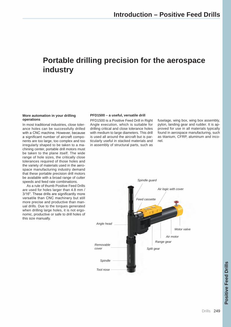
Posi
tive
Feed
Dril
ls
Drills 249
Air logic with cover
Split gear
Feed cassette
Spindle guard
Range gear
Air motor
Motor valve
Angle head
Removable cover
Spindle
Tool nose
Introduction – Positive Feed Drills
More automation in your drilling operationsIn most traditional industries, close toler-ance holes can be successfully drilled with a CNC machine. However, because a significant number of aircraft compo-nents are too large, too complex and too irregularly shaped to be taken to a ma-chining center, portable drill motors must be taken to the plane itself. The wide range of hole sizes, the critically close tolerances required of those holes and the variety of materials used in the aero-space manufacturing industry demand that these portable precision drill motors be available with a broad range of cutter speeds and feed rate combinations.
As a rule of thumb Positive Feed Drills are used for holes larger than 4.8 mm / 3/16". These drills are significantly more versatile than CNC machinery but still more precise and productive than man-ual drills. Due to the torques generated when drilling large holes, it is not ergo-nomic, productive or safe to drill holes of this size manually.
PFD1500 – a useful, versatile drillPFD1500 is a Positive Feed Drill in Right Angle execution, which is suitable for drilling critical and close tolerance holes with medium to large diameters. This drill is used all around the aircraft but is par-ticularly useful in stacked materials and in assembly of structural parts, such as
Portable drilling precision for the aerospace industry
fuselage, wing box, wing box assembly, pylon, landing gear and rudder. It is ap-proved for use in all materials typically found in aerospace manufacturing, such as titanium, CFRP, aluminum and inco-nel.
Am_Drills.indd 249 2012-02-07 13:54:08
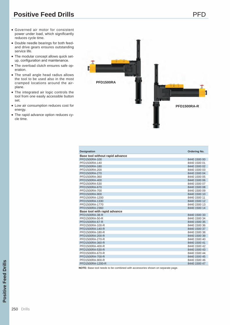
Posi
tive
Feed
Dril
ls
250 Drills
PFD1500RA
PFD1500RA-R
Positive Feed Drills PFD
l Governed air motor for consistent power under load, which significantly reduces cycle time.
l Double needle bearings for both feed- and drive gears ensures outstanding service life.
l The modular concept allows quick set-up, configuration and maintenance.
l The overload clutch ensures safe op-eration.
l The small angle head radius allows the tool to be used also in the most cramped locations around the air-plane.
l The integrated air logic controls the tool from one easily accessible button set.
l Low air consumption reduces cost for energy.
l The rapid advance option reduces cy-cle time.
Designation Ordering No.Base tool without rapid advancePFD1500RA-100 8440 1500 00PFD1500RA-140 8440 1500 01PFD1500RA-180 8440 1500 02PFD1500RA-200 8440 1500 03PFD1500RA-270 8440 1500 04PFD1500RA-360 8440 1500 05PFD1500RA-400 8440 1500 06PFD1500RA-530 8440 1500 07PFD1500RA-670 8440 1500 08PFD1500RA-700 8440 1500 09PFD1500RA-900 8440 1500 10PFD1500RA-1200 8440 1500 11PFD1500RA-1330 8440 1500 12PFD1500RA-1770 8440 1500 13PFD1500RA-2360 8440 1500 14Base tool with rapid advancePFD1500RA-38-R 8440 1500 33PFD1500RA-50-R 8440 1500 34PFD1500RA-67-R 8440 1500 35PFD1500RA-100-R 8440 1500 36 PFD1500RA-140-R 8440 1500 37PFD1500RA-180-R 8440 1500 38PFD1500RA-200-R 8440 1500 39PFD1500RA-270-R 8440 1500 40PFD1500RA-360-R 8440 1500 41PFD1500RA-400-R 8440 1500 42PFD1500RA-530-R 8440 1500 43PFD1500RA-670-R 8440 1500 44PFD1500RA-700-R 8440 1500 45PFD1500RA-900-R 8440 1500 46PFD1500RA-1200-R 8440 1500 47
NOTE: Base tool needs to be combined with accessories shown on separate page.
Am_Drills.indd 250 2012-02-07 13:54:11
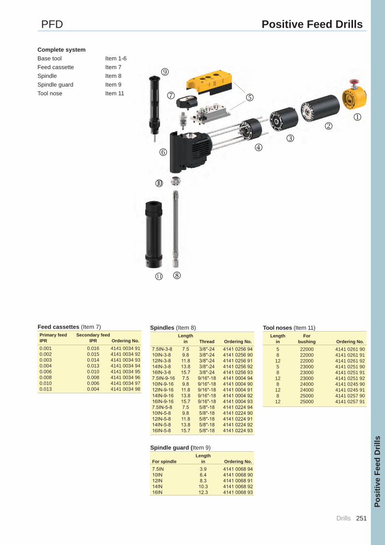
Posi
tive
Feed
Dril
ls
Drills 251
o
n
jk
lm
11
PFD Positive Feed Drills
Complete systemBase tool Item 1-6Feed cassette Item 7Spindle Item 8Spindle guard Item 9Tool nose Item 11
Spindle guard (Item 9) Length For spindle in Ordering No.7.5IN 3.9 4141 0068 9410IN 6.4 4141 0068 9012IN 8.3 4141 0068 9114IN 10.3 4141 0068 9216IN 12.3 4141 0068 93
Spindles (Item 8) Length in Thread Ordering No.7.5IN‑3‑8 7.5 3/8"‑24 4141 0256 9410IN‑3‑8 9.8 3/8"‑24 4141 0256 9012IN‑3‑8 11.8 3/8"‑24 4141 0256 9114IN‑3‑8 13.8 3/8"‑24 4141 0256 9216IN‑3‑8 15.7 3/8"‑24 4141 0256 937.5IN‑9‑16 7.5 9/16"‑18 4141 0004 9410IN‑9‑16 9.8 9/16"‑18 4141 0004 9012IN‑9‑16 11.8 9/16"‑18 4141 0004 9114IN‑9‑16 13.8 9/16"‑18 4141 0004 9216IN‑9‑16 15.7 9/16"‑18 4141 0004 937.5IN‑5‑8 7.5 5/8"‑18 4141 0224 9410IN‑5‑8 9.8 5/8"‑18 4141 0224 9012IN‑5‑8 11.8 5/8"‑18 4141 0224 9114IN‑5‑8 13.8 5/8"‑18 4141 0224 9216IN‑5‑8 15.7 5/8"‑18 4141 0224 93
Tool noses (Item 11) Length For in bushing Ordering No. 5 22000 4141 0261 90 8 22000 4141 0261 91 12 22000 4141 0261 92 5 23000 4141 0251 90 8 23000 4141 0251 91 12 23000 4141 0251 92 8 24000 4141 0245 90 12 24000 4141 0245 91 8 25000 4141 0257 90 12 25000 4141 0257 91
Feed cassettes (Item 7)Primary feed Secondary feed IPR IPR Ordering No.0.001 0.016 4141 0034 910.002 0.015 4141 0034 920.003 0.014 4141 0034 930.004 0.013 4141 0034 940.006 0.010 4141 0034 950.008 0.008 4141 0034 960.010 0.006 4141 0034 970.013 0.004 4141 0034 98
Am_Drills.indd 251 2012-02-07 13:54:14
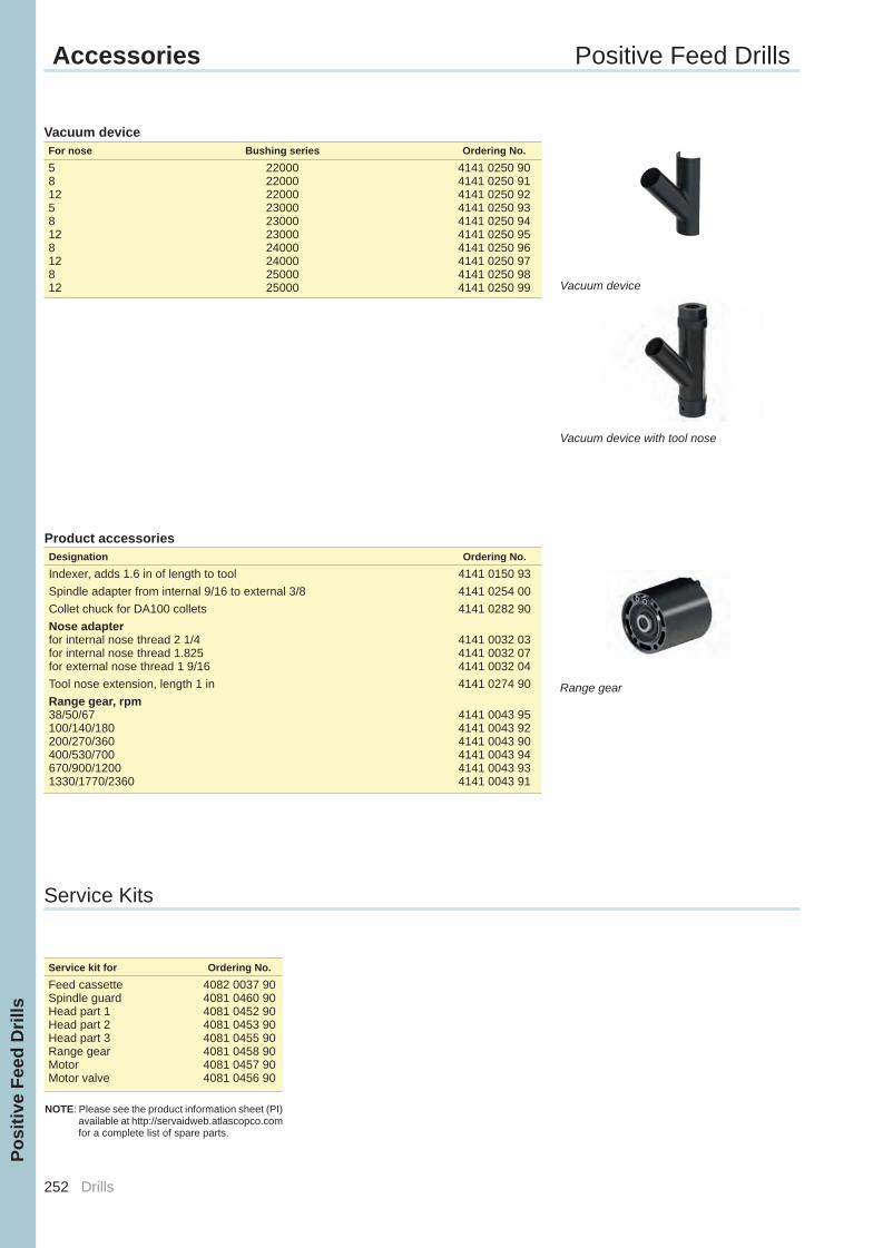
Posi
tive
Feed
Dril
ls
252 Drills
Accessories Positive Feed Drills
Service Kits
NOTE: Please see the product information sheet (PI) available at http://servaidweb.atlascopco.com for a complete list of spare parts.
Vacuum deviceFor nose Bushing series Ordering No.5 22000 4141 0250 908 22000 4141 0250 9112 22000 4141 0250 925 23000 4141 0250 938 23000 4141 0250 9412 23000 4141 0250 958 24000 4141 0250 9612 24000 4141 0250 978 25000 4141 0250 9812 25000 4141 0250 99
Service kit for Ordering No.Feed cassette 4082 0037 90Spindle guard 4081 0460 90Head part 1 4081 0452 90Head part 2 4081 0453 90Head part 3 4081 0455 90Range gear 4081 0458 90Motor 4081 0457 90Motor valve 4081 0456 90
Vacuum device
Range gear
Product accessories Designation Ordering No.Indexer, adds 1.6 in of length to tool 4141 0150 93Spindle adapter from internal 9/16 to external 3/8 4141 0254 00Collet chuck for DA100 collets 4141 0282 90Nose adapter for internal nose thread 2 1/4 4141 0032 03for internal nose thread 1.825 4141 0032 07for external nose thread 1 9/16 4141 0032 04Tool nose extension, length 1 in 4141 0274 90Range gear, rpm 38/50/67 4141 0043 95100/140/180 4141 0043 92200/270/360 4141 0043 90400/530/700 4141 0043 94670/900/1200 4141 0043 931330/1770/2360 4141 0043 91
Vacuum device with tool nose
Am_Drills.indd 252 2012-02-07 13:54:16
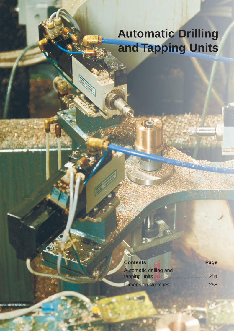
Automatic Drillingand Tapping Units
Contents PageAutomatic drilling andtapping units ...................................... 254Dimension sketches .......................... 258
Am_Automaticdrilling.indd 253 2012-02-07 14:05:25
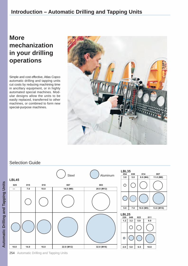
A
utom
atic
Dril
ling
and
Tapp
ing
Uni
ts
254 Automatic Drilling and Tapping Units
LBL45
14.010.0 16.0 22.0 (M12) 32.0 (M16)
010 007 003— 7.0 14.0 (M8)10.0 20.0 (M12)025 015
LBL35
5.0 7.0 10.0 (M5) 13.0 (M10)
030 014 0073.0 5.0 8.0 (M4) 11.0 (M8)054
5.02.0 6.5 10.0
022 0111.2 3.2 5.0 8.0220 049
LBL25
Moremechanization in your drilling operations
Simple and cost effective, Atlas Copco automatic drilling and tapping units cut costs by reducing machining time in ancillary equipment, or in highly automated special machines. Mod-ular designs allow the units to be easily replaced, transferred to other machines, or combined to form new special-purpose machines.
Introduction – Automatic Drilling and Tapping Units
Selection Guide
AluminumSteel
Am_Automaticdrilling.indd 254 2012-02-07 14:05:27
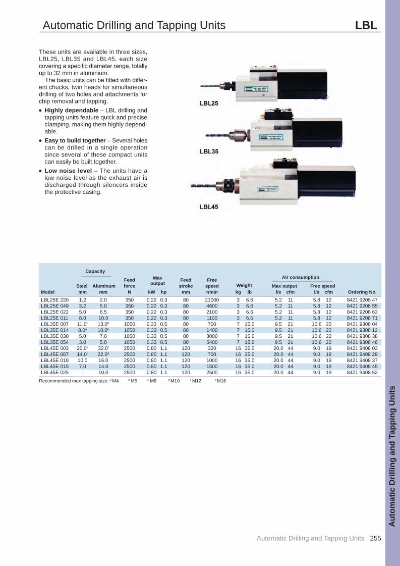
Automatic Drilling and Tapping Units 255
Aut
omat
ic D
rillin
g an
d Ta
ppin
g U
nits
Automatic Drilling and Tapping Units LBL
These units are available in three sizes, LBL25, LBL35 and LBL45, each size covering a specifi c diameter range, totally up to 32 mm in aluminium.
The basic units can be fi tted with differ-ent chucks, twin heads for simultaneous drilling of two holes and attachments for chip removal and tapping.� Highly dependable – LBL drilling and
tapping units feature quick and precise clamping, making them highly depend-able.
� Easy to build together – Several holes can be drilled in a single operation since several of these compact units can easily be built together.
� Low noise level – The units have a low noise level as the exhaust air is discharged through silencers inside the protective casing.
Capacity
Max
Air consumption Feed output
Feed Free Weight Steel Aluminum force stroke speed Max output Free speed
Model mm mm N kW hp mm r/min kg lb l/s cfm l/s cfm Ordering No.LBL25E 220 1.2 2.0 350 0.22 0.3 80 21000 3 6.6 5.2 11 5.8 12 8421 9208 47LBL25E 049 3.2 5.0 350 0.22 0.3 80 4600 3 6.6 5.2 11 5.8 12 8421 9208 55LBL25E 022 5.0 6.5 350 0.22 0.3 80 2100 3 6.6 5.2 11 5.8 12 8421 9208 63LBL25E 011 8.0 10.0 350 0.22 0.3 80 1100 3 6.6 5.2 11 5.8 12 8421 9208 71LBL35E 007 11.0c 13.0d 1050 0.33 0.5 80 700 7 15.0 9.5 21 10.6 22 8421 9308 04LBL35E 014 8.0a 10.0b 1050 0.33 0.5 80 1400 7 15.0 9.5 21 10.6 22 8421 9308 12LBL35E 030 5.0 7.0 1050 0.33 0.5 80 3000 7 15.0 9.5 21 10.6 22 8421 9308 38LBL35E 054 3.0 5.0 1050 0.33 0.5 80 5400 7 15.0 9.5 21 10.6 22 8421 9308 46LBL45E 003 20.0e 32.0f 2500 0.80 1.1 120 320 16 35.0 20.0 44 9.0 19 8421 9408 03LBL45E 007 14.0c 22.0d 2500 0.80 1.1 120 700 16 35.0 20.0 44 9.0 19 8421 9408 29LBL45E 010 10.0 16.0 2500 0.80 1.1 120 1000 16 35.0 20.0 44 9.0 19 8421 9408 37LBL45E 015 7.0 14.0 2500 0.80 1.1 120 1500 16 35.0 20.0 44 9.0 19 8421 9408 45LBL45E 025 - 10.0 2500 0.80 1.1 120 2500 16 35.0 20.0 44 9.0 19 8421 9408 52
Recommended max tapping size: a M4 b M5 c M8 d M10 e M12 f M16
Am_Automaticdrilling.indd 255 2012-02-07 14:05:28
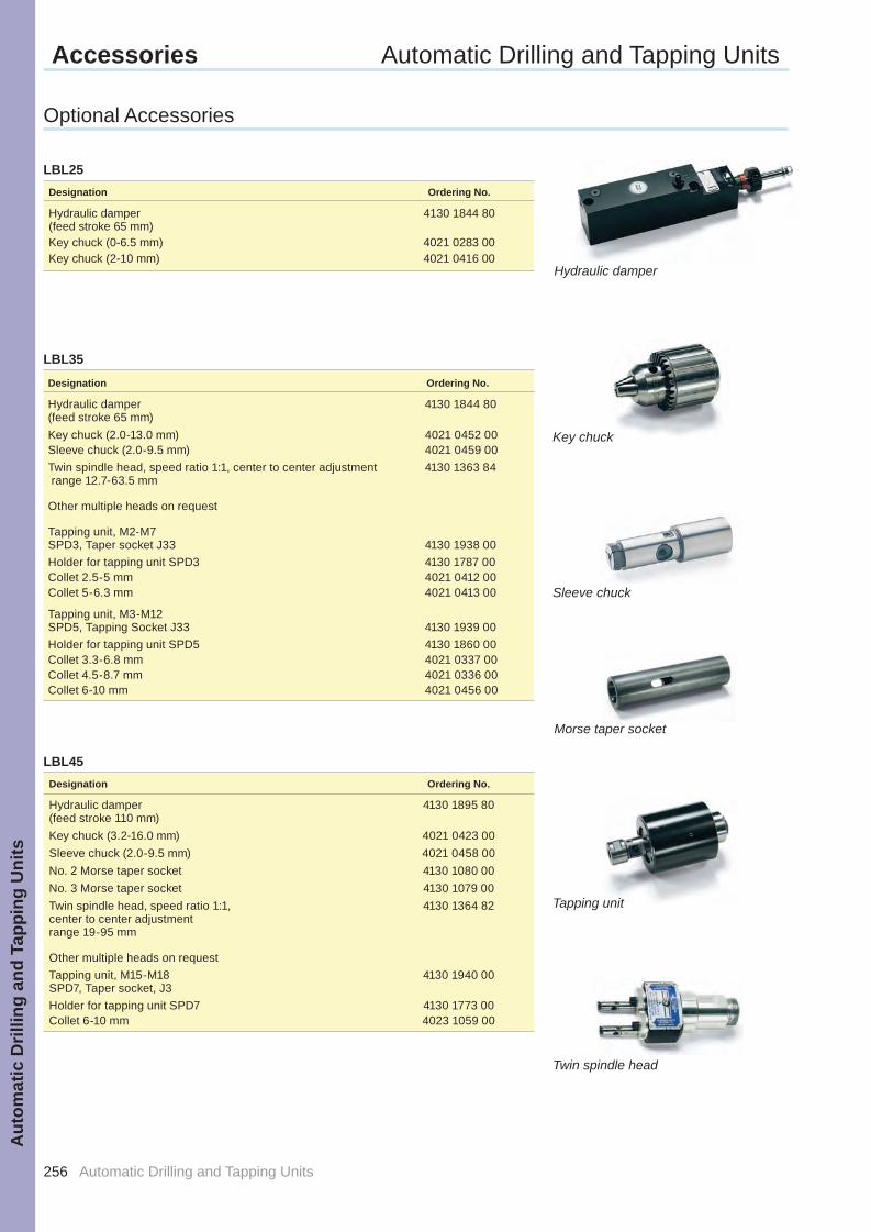
A
utom
atic
Dril
ling
and
Tapp
ing
Uni
ts
256 Automatic Drilling and Tapping Units
Accessories Automatic Drilling and Tapping Units
Hydraulic damper
Key chuck
Sleeve chuck
Tapping unit
Twin spindle head
Morse taper socket
Optional Accessories
LBL25Designation Ordering No.
Hydraulic damper 4130 1844 80(feed stroke 65 mm) Key chuck (0-6.5 mm) 4021 0283 00Key chuck (2-10 mm) 4021 0416 00
LBL35
Designation Ordering No.
Hydraulic damper 4130 1844 80(feed stroke 65 mm) Key chuck (2.0-13.0 mm) 4021 0452 00Sleeve chuck (2.0-9.5 mm) 4021 0459 00Twin spindle head, speed ratio 1:1, center to center adjustment 4130 1363 84 range 12.7-63.5 mm
Other multiple heads on request
Tapping unit, M2-M7 SPD3, Taper socket J33 4130 1938 00Holder for tapping unit SPD3 4130 1787 00Collet 2.5-5 mm 4021 0412 00Collet 5-6.3 mm 4021 0413 00
Tapping unit, M3-M12 SPD5, Tapping Socket J33 4130 1939 00Holder for tapping unit SPD5 4130 1860 00Collet 3.3-6.8 mm 4021 0337 00Collet 4.5-8.7 mm 4021 0336 00Collet 6-10 mm 4021 0456 00
LBL45Designation Ordering No.
Hydraulic damper 4130 1895 80(feed stroke 110 mm) Key chuck (3.2-16.0 mm) 4021 0423 00Sleeve chuck (2.0-9.5 mm) 4021 0458 00No. 2 Morse taper socket 4130 1080 00No. 3 Morse taper socket 4130 1079 00Twin spindle head, speed ratio 1:1, 4130 1364 82center to center adjustment range 19-95 mm
Other multiple heads on requestTapping unit, M15-M18 4130 1940 00SPD7, Taper socket, J3Holder for tapping unit SPD7 4130 1773 00Collet 6-10 mm 4023 1059 00
Am_Automaticdrilling.indd 256 2012-02-07 14:05:33
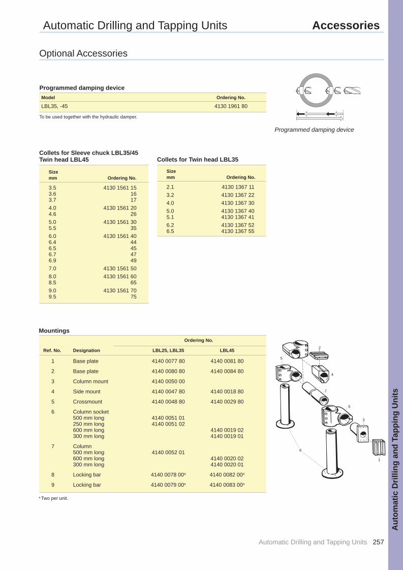
Automatic Drilling and Tapping Units 257
Aut
omat
ic D
rillin
g an
d Ta
ppin
g U
nits
1
2
3
4
5
6
7
5
Automatic Drilling and Tapping Units Accessories
Sizemm Ordering No.
2.1 4130 1367 113.2 4130 1367 224.0 4130 1367 305.0 4130 1367 405.1 4130 1367 416.2 4130 1367 526.5 4130 1367 55
Collets for Sleeve chuck LBL35/45 Twin head LBL45
Sizemm Ordering No.
3.5 4130 1561 153.6 163.7 174.0 4130 1561 204.6 265.0 4130 1561 305.5 356.0 4130 1561 406.4 446.5 456.7 476.9 497.0 4130 1561 508.0 4130 1561 608.5 659.0 4130 1561 709.5 75
Collets for Twin head LBL35
Optional Accessories
Mountings Ordering No.
Ref. No. Designation LBL25, LBL35 LBL45
1 Base plate 4140 0077 80 4140 0081 80
2 Base plate 4140 0080 80 4140 0084 80
3 Column mount 4140 0050 00
4 Side mount 4140 0047 80 4140 0018 80
5 Crossmount 4140 0048 80 4140 0029 80
6 Column socket 500 mm long 4140 0051 01 250 mm long 4140 0051 02 600 mm long 4140 0019 02 300 mm long 4140 0019 01
7 Column 500 mm long 4140 0052 01 600 mm long 4140 0020 02 300 mm long 4140 0020 01
8 Locking bar 4140 0078 00a 4140 0082 00a
9 Locking bar 4140 0079 00a 4140 0083 00a
a Two per unit.
Programmed damping device
Model Ordering No.
LBL35, -45 4130 1961 80
Programmed damping device
To be used together with the hydraulic damper.
Am_Automaticdrilling.indd 257 2012-02-07 14:05:33
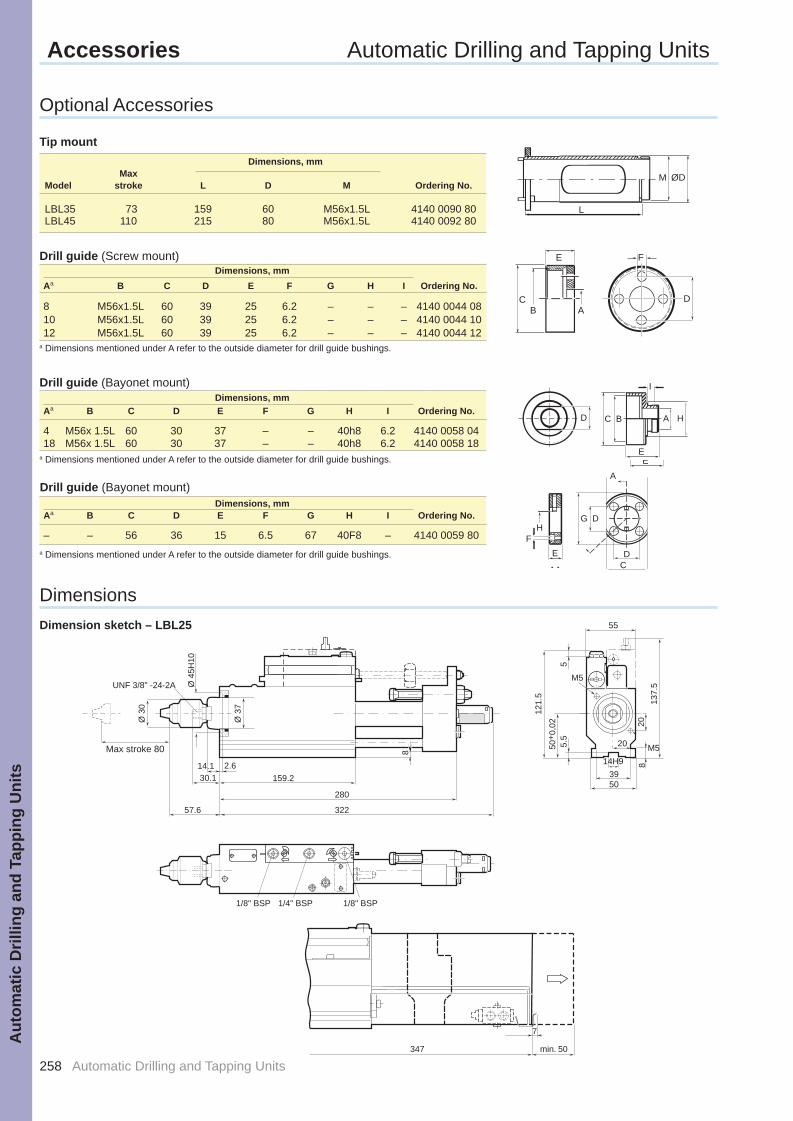
A
utom
atic
Dril
ling
and
Tapp
ing
Uni
ts
258 Automatic Drilling and Tapping Units
Ø 3
0
Ø 3
7
UNF 3/8" -24-2A Ø 4
5H10
14.1 2.6
159.2
280
322 57.6
30.1
8
1/8" BSP 1/8" BSP 1/4" BSP
5.5
5 50
+0,
02 12
1.5
137.
5
55
20
M5
8
50 39
14H9
7
347 min. 50
M5 20
L
M ØD
C D
FE
B A
D C
E
B
I
H
E
HF
G D
DC
A
AA
AD C
E
B
I
H
E
HF
G D
DC
A
AA
A
Dimensions, mmAa B C D E F G H I Ordering No.
– – 56 36 15 6.5 67 40F8 – 4140 0059 80
Dimension sketch – LBL25
Max stroke 80
Accessories Automatic Drilling and Tapping Units
Optional Accessories
Tip mount Dimensions, mm MaxModel stroke L D M Ordering No.
LBL35 73 159 60 M56x1.5L 4140 0090 80LBL45 110 215 80 M56x1.5L 4140 0092 80
Drill guide (Screw mount) Dimensions, mmAa B C D E F G H I Ordering No.
8 M56x1.5L 60 39 25 6.2 – – – 4140 0044 0810 M56x1.5L 60 39 25 6.2 – – – 4140 0044 1012 M56x1.5L 60 39 25 6.2 – – – 4140 0044 12
Drill guide (Bayonet mount) Dimensions, mmAa B C D E F G H I Ordering No.
4 M56x 1.5L 60 30 37 – – 40h8 6.2 4140 0058 0418 M56x 1.5L 60 30 37 – – 40h8 6.2 4140 0058 18
a Dimensions mentioned under A refer to the outside diameter for drill guide bushings.
a Dimensions mentioned under A refer to the outside diameter for drill guide bushings.
Dimensions
Drill guide (Bayonet mount)
a Dimensions mentioned under A refer to the outside diameter for drill guide bushings.
Am_Automaticdrilling.indd 258 2012-02-07 14:05:34
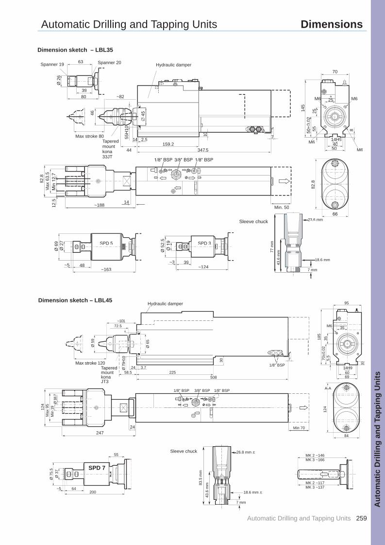
Automatic Drilling and Tapping Units 259
Aut
omat
ic D
rillin
g an
d Ta
ppin
g U
nits
63Ø
26
3980
46~82
2.555H
100
44
144159.2
347.5
100 77
82.8
12.5 14
~188
Ø69
~16348~5
Ø27
Ø52
.5
~3 39~124
SPD 5 SPD 3
145
50
70
25255
25±
0.02
55
M6
8
4000
82.8
M6
M6M
M6M
14H9H14H9
Max
63.
5
Min. 50
77m
m
23.6 mm
18.6 mm
7 mm
43.6
mm
Ø 5
9
Ø 6
5
7
1/8" BSP
30
50822558.5
3.724Ø 7
5H10
~10172.5
Min 70
124
Max
95
Min
19
247
1/8" BSP 1/8" BSP3/8" BSP
Ø 1
8.7
24
SPD 7
Ø 7
5.5
Ø 3
7
200~5 64
55 MK 2 ~146MK 3 ~166
MK 2 ~117MK 3 ~137
185
69
3570
±0.
02
14H9
124
84
A-A
355.
5
10
60
M6
95
83.5
mm
26.8 mm Æ
18.6 mm Æ
7 mm
43.6
mm
Dimension sketch – LBL35
Spanner 19 Spanner 20 Hydraulic damper
Max stroke 80Taperedmountkona33JT
Sleeve chuck
Automatic Drilling and Tapping Units Dimensions
Dimension sketch – LBL45 Hydraulic damper
Max stroke 120TaperedmountkonaJT3
Sleeve chuck
Am_Automaticdrilling.indd 259 2012-02-07 14:05:36
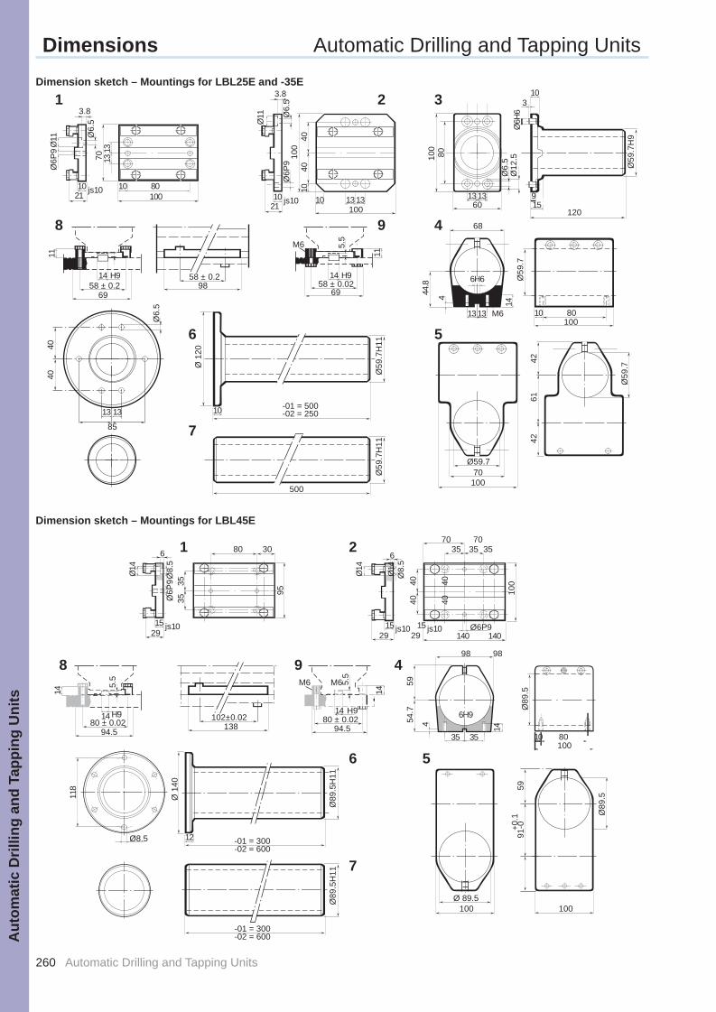
A
utom
atic
Dril
ling
and
Tapp
ing
Uni
ts
260 Automatic Drilling and Tapping Units
1 2
3535
80 30
95
Ø14
6
Ø8.
5Ø
6P9
2915 js10
Ø14
6
Ø8.
5
2915 js10
4040
35 3570
100
140Ø6P9
8
14
14 H980 ± 0.02
94.5
5.5
102±0.02138
80 ± 0.0294.5
14
9
14 H9
5.5
M6
4
454.7
59
14
35 35
6H9
98
Ø14
2915 js10
4040
3570
140
M6
98
Ø89
.5
1008010
118
Ø8.5
Ø 1
40
12 -01 = 300-02 = 600
Ø89
.5H
11
6
-01 = 300-02 = 600
Ø89
.5H
11
7
Ø89
.5
59+
0.1
91-0
100Ø 89.5
100
5
100
80
131360
Ø6.
5Ø
12.5
3
4120
9
Ø59
.7H
9
15
Ø6H
6
103
5
68
1313 M6
4
44.8
6H6
14Ø
59.7
1008010
100
Ø59.770
Ø59
.7
4261
42
3.8
10
Ø6.
5
Ø11
21js10
Ø6P
9
1040
4010
0
10 1313100
2
5.5
14 H958 ± 0.02
69
11
M6
9
Ø 1
20
10 -01 = 500-02 = 250
Ø59
.7H
11Ø
59.7
H11
6
7
500
3.8
10
1
8
Ø6.
5
Ø6P
9Ø
11
1010021
js10
70 1313
80
11
5.5
14 H958 ± 0.2
69
58 ± 0.298
Ø6.
5
13 13
85
4040
Dimension sketch – Mountings for LBL45E
Dimension sketch – Mountings for LBL25E and ‑35E
Dimensions Automatic Drilling and Tapping Units
Am_Automaticdrilling.indd 260 2012-02-07 14:05:37

Air Line Accessories
Contents PageIntroduction ........................................262Product safety....................................263Air preparation units ..........................264Optimizer air tool oil ...........................268Quick couplings .................................269Claw couplings ..................................275Ball valves .........................................276Swivel connectors..............................277Fittings ...............................................278Hoses ................................................279Productivity kits..................................285Pre-mounted hose kits.......................286Hose reels .........................................287Balancers...........................................291Blow gun ............................................294Test equipment ..................................294
Am_AirLineAccessories.indd 261 2012-02-08 13:51:37

Air
Line
Acc
esso
ries
262 Air Line Accessories
To ensure that you benefit from the full potential power of your tools, Atlas Copco has developed a full range of air line accessories for use with Atlas Copco tools and air motors. All accessories can be used for other applications and pneumatic equipment.
Introduction – Air Line Accessories
ProductivityBy using Atlas Copco’s air line accesso-ries you ensure that you have a correct air line installation for your tool. This will provide the correct air flow to the tool, ensuring that you benefit from its full potential power, and that you reach the correct torque in torque-controlled tools. By using the recommended accessories you will also minimize the service re-quirements of the tool.
Energy efficiencyWith a correct installation you will not only achieve the tool’s full potential power, you will also reduce energy costs. All Atlas Copco accessories are designed for minimum pressure drop, which ensures that the compressor is not “working overtime”.
SafetyAll accessories are designed to meet the highest demands for a safe working en-vironment. Atlas Copco has developed a wide range of safety couplings, balanc-ers and hose reels to meet today's high standards in terms of workplace safety.
ErgonomicsOperator health and well-being are im-portant factors. Atlas Copco accessories, such as torque arms, balancers, screw presenters and reaction bars, enable you to configure ergonomically correct work-stations for your operators.
QualityAll Atlas Copco accessories are made of the highest quality materials for long production cycles and to withstand rough treatment. Choose Atlas Copco accesso-ries and you will be sure of high quality products.
Ensure that your tools achieve their full potential
Am_AirLineAccessories.indd 262 2012-02-08 13:54:47
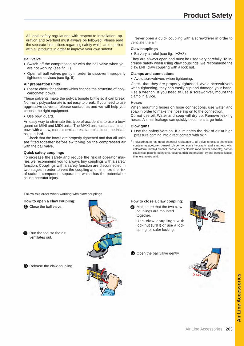
Air
Line
Acc
esso
ries
Air Line Accessories 263
Product Safety
How to close a claw coupling:Make sure that the two claw couplings are mounted together.Use claw couplings with lock nut (LNH) or use a lock spring for safer locking.
All local safety regulations with respect to installation, op-eration and overhaul must always be followed. Please read the separate instructions regarding safety which are supplied with all products in order to improve your own safety!
Ball valvel Switch off the compressed air with the ball valve when you
are not working (see fig. 1).l Open all ball valves gently in order to discover improperly
tightened devices (see fig. 5).
Air preparation unitsl Please check for solvents which change the structure of poly-
carbonatea bowls.These solvents make the polycarbonate brittle so it can break. Normally polycarbonate is not easy to break. If you need to use aggressive solvents, please contact us and we will help you choose the right equipment.l Use bowl guard.An easy way to eliminate this type of accident is to use a bowl guard on MINI and MIDI units. The MAXI unit has an aluminum bowl with a new, more chemical resistant plastic on the inside as standard.
Check that the bowls are properly tightened and that all units are fitted together before switching on the compressed air with the ball valve.
Quick safety couplingsTo increase the safety and reduce the risk of operator inju-ries we recommend you to always buy couplings with a safety function. Couplings with a safety function are disconnected in two stages in order to vent the coupling and minimize the risk of sudden component separation, which has the potential to cause operator injury.
Never open a quick coupling with a screwdriver in order to ventilate the air.
Claw couplingsl Be very careful (see fig. 1+2+3).They are always open and must be used very carefully. To in-crease safety when using claw couplings, we recommend the claw LNH claw coupling with a lock nut.
Clamps and connectionsl Avoid screwdrivers when tightening.Check that they are properly tightened. Avoid screwdrivers when tightening, they can easily slip and damage your hand. Use a wrench. If you need to use a screwdriver, mount the clamp in a vice.
HosesWhen mounting hoses on hose connections, use water and soap in order to make the hose slip on to the connection.Do not use oil. Water and soap will dry up. Remove leaking hoses. A small leakage can quickly become a large hole.
Blow gunsl Use the safety version. It eliminates the risk of air at high
pressure coming into direct contact with skin.a Polycarbonate has good chemical resistance to all solvents except chemicals
containing acetone, benzol, glycerine, some hydraulic and synthetic oils, chloroform, methyl alcohol, carbon tetrachloride (and similar solvents), carbon disulphide, perchloroethylene, toluene, trichloroethylene, xylene (nitrocellulose, thinner), acetic acid.
Follow this order when working with claw couplings.
1
2
3
4
Open the ball valve gently.5
How to open a claw coupling:Close the ball valve.
Run the tool so the air ventilates out.
Release the claw coupling.
Am_AirLineAccessories.indd 263 2012-02-08 13:58:33

Air
Line
Acc
esso
ries
264 Air Line Accessories
Introduction – Air Preparation Units
Filter – FILWater and dirt in your compressed air system will cause extensive corrosion damage and wear.
ProductivityAtlas Copco fi lters are equipped with a cyclone system. Using centrifugal force, this separates out a high percentage of the heavier solid water particles, while the fi lter ensures that the amount of dirt entering your tool is kept to a minimum. This means longer working cycles for the tools and minimum service time.
Regulator– REGAtlas Copco regulators ensure optimal flow at the specific flow rates required by Atlas Copco tools, or any other pneu-matic tools.
Energy effi ciencyBy installing a regulator you will ensure that there will not be any unnecessary consumption of compressed air. The reg-ulators reduce a variable primary pres-sure to a practically constant secondary pressure with a minimum of pressure drop.
ProductivityThe regulator will optimize the perfor-mance of your tool, ensure torque accu-racy and boost productivity.
Atlas Copco air preparation units are designed to help you get maximum pro-ductivity from your tools. They ensure minimal pressure drop and thus minimum energy losses in the air distribution system, benefi ting the environment and cut-ting your operating costs. The lifetimes of your tools will be extended by using air preparation units and with that comes lower repair costs and less downtime.
A correct air installation ensures productivity and good total economy.
Filter – FIL
Regulator – REG
Lubricator – DIM
Lubricator – DIMAtlas Copco oil lubricators ensure a long, efficient and trouble-free life for your pneumatic tools and components.
ProductivityThe use of a lubricator will increase the power in vane motors by about 10-15%.
Energy effi ciencyWith the use of a lubricator you will pro-long the lifetime of a vane motor up to three times and the motor will work much more effi ciently, and with less friction.
Get maximum productivity from your tools
Am_AirLineAccessories.indd 264 2012-02-08 14:05:50
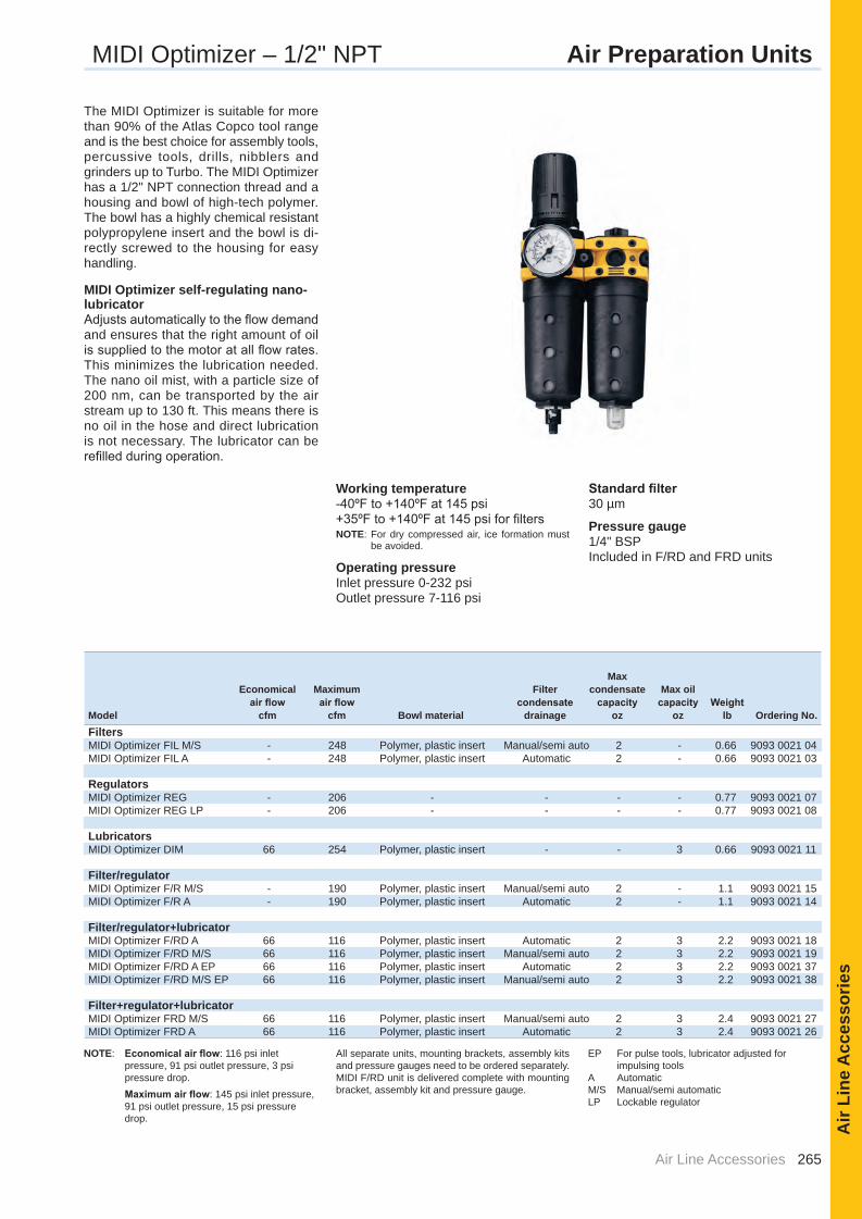
Air
Line
Acc
esso
ries
Air Line Accessories 265
MIDI Optimizer – 1/2" NPT Air Preparation Units
The MIDI Optimizer is suitable for more than 90% of the Atlas Copco tool range and is the best choice for assembly tools, percussive tools, drills, nibblers and grinders up to Turbo. The MIDI Optimizer has a 1/2" NPT connection thread and a housing and bowl of high-tech polymer. The bowl has a highly chemical resistant polypropylene insert and the bowl is di-rectly screwed to the housing for easy handling.
MIDI Optimizer self-regulating nano-lubricator Adjusts automatically to the flow demand and ensures that the right amount of oil is supplied to the motor at all flow rates. This minimizes the lubrication needed. The nano oil mist, with a particle size of 200 nm, can be transported by the air stream up to 130 ft. This means there is no oil in the hose and direct lubrication is not necessary. The lubricator can be refilled during operation.
Working temperature-40ºF to +140ºF at 145 psi+35ºF to +140ºF at 145 psi for filtersNOTE: For dry compressed air, ice formation must
be avoided.
Operating pressureInlet pressure 0-232 psiOutlet pressure 7-116 psi
Standard filter30 µm
Pressure gauge1/4" BSPIncluded in F/RD and FRD units
Max Economical Maximum Filter condensate Max oil air flow air flow condensate capacity capacity Weight Model cfm cfm Bowl material drainage oz oz lb Ordering No.FiltersMIDI Optimizer FIL M/S - 248 Polymer, plastic insert Manual/semi auto 2 - 0.66 9093 0021 04MIDI Optimizer FIL A - 248 Polymer, plastic insert Automatic 2 - 0.66 9093 0021 03
Regulators MIDI Optimizer REG - 206 - - - - 0.77 9093 0021 07MIDI Optimizer REG LP - 206 - - - - 0.77 9093 0021 08
Lubricators MIDI Optimizer DIM 66 254 Polymer, plastic insert - - 3 0.66 9093 0021 11
Filter/regulator MIDI Optimizer F/R M/S - 190 Polymer, plastic insert Manual/semi auto 2 - 1.1 9093 0021 15MIDI Optimizer F/R A - 190 Polymer, plastic insert Automatic 2 - 1.1 9093 0021 14
Filter/regulator+lubricator MIDI Optimizer F/RD A 66 116 Polymer, plastic insert Automatic 2 3 2.2 9093 0021 18MIDI Optimizer F/RD M/S 66 116 Polymer, plastic insert Manual/semi auto 2 3 2.2 9093 0021 19MIDI Optimizer F/RD A EP 66 116 Polymer, plastic insert Automatic 2 3 2.2 9093 0021 37MIDI Optimizer F/RD M/S EP 66 116 Polymer, plastic insert Manual/semi auto 2 3 2.2 9093 0021 38
Filter+regulator+lubricator MIDI Optimizer FRD M/S 66 116 Polymer, plastic insert Manual/semi auto 2 3 2.4 9093 0021 27MIDI Optimizer FRD A 66 116 Polymer, plastic insert Automatic 2 3 2.4 9093 0021 26
NOTE: Economical air flow: 116 psi inlet pressure, 91 psi outlet pressure, 3 psi pressure drop.
Maximum air flow: 145 psi inlet pressure, 91 psi outlet pressure, 15 psi pressure drop.
All separate units, mounting brackets, assembly kits and pressure gauges need to be ordered separately. MIDI F/RD unit is delivered complete with mounting bracket, assembly kit and pressure gauge.
EP For pulse tools, lubricator adjusted for impulsing tools A Automatic M/S Manual/semi automatic LP Lockable regulator
Am_AirLineAccessories.indd 265 2012-02-08 14:06:09
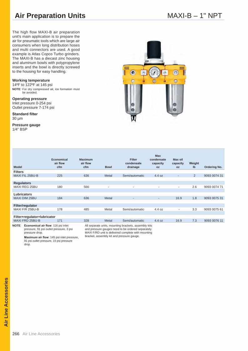
Air
Line
Acc
esso
ries
266 Air Line Accessories
The high flow MAXI-B air preparation unit's main application is to prepare the air for pneumatic tools which are large air consumers when long distribution hoses and multi connectors are used. A good example is Atlas Copco Turbo grinders.The MAXI-B has a diecast zinc housing and aluminum bowls with polypropylene inserts and the bowl is directly screwed to the housing for easy handling.
Working temperature14ºF to 122ºF at 145 psiNOTE: For dry compressed air, ice formation must
be avoided.
Operating pressureInlet pressure 0-254 psiOutlet pressure 7-174 psi
Standard fi lter30 µm
Pressure gauge1/4" BSP
Air Preparation Units MAXI-B – 1" NPT
Max Economical Maximum Filter condensate Max oil air fl ow air fl ow condensate capacity capacity Weight Model cfm cfm Bowl drainage oz oz lb Ordering No.Filters MAXI FIL 25BU-B 225 636 Metal Semi/automatic 4.4 oz - 2 9093 0074 31
Regulators MAXI REG 25BU 180 566 - - - - 2.6 9093 0074 71
Lubricators MAXI DIM 25BU 184 636 Metal - - 16.9 1.8 9093 0075 31
Filter/regulator MAXI F/R 25BU-B 178 485 Metal Semi/automatic 4.4 oz - 3.3 9093 0075 61
Filter+regulator+lubricator MAXI FRD 25BU-B 171 328 Metal Semi/automatic 4.4 oz 16.9 7.3 9093 0076 11
NOTE: Economical air fl ow: 116 psi inlet pressure, 91 psi outlet pressure, 3 psi pressure drop.
Maximum air fl ow: 145 psi inlet pressure, 91 psi outlet pressure, 15 psi pressure drop.
All separate units, mounting brackets, assembly kits and pressure gauges need to be ordered separately. MAXI F/RD unit is delivered complete with mounting bracket, assembly kit and pressure gauge.
Am_AirLineAccessories.indd 266 2012-02-08 14:06:22
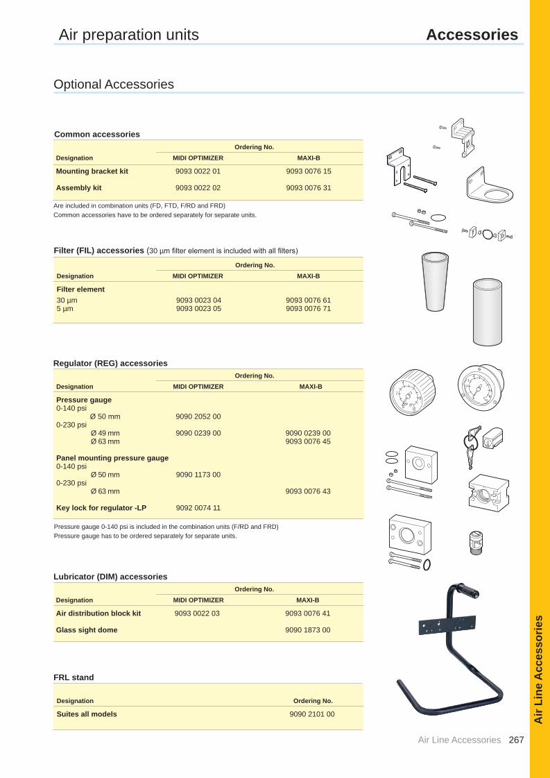
Air
Line
Acc
esso
ries
Air Line Accessories 267
Ordering No.Designation MIDI OPTIMIZER MAXI-B
Mounting bracket kit 9093 0022 01 9093 0076 15
Assembly kit 9093 0022 02 9093 0076 31
Optional Accessories
Filter (FIL) accessories (30 µm filter element is included with all filters)
Ordering No.Designation MIDI OPTIMIZER MAXI-B
Filter element 30 µm 9093 0023 04 9093 0076 615 µm 9093 0023 05 9093 0076 71
Lubricator (DIM) accessories
Are included in combination units (FD, FTD, F/RD and FRD)Common accessories have to be ordered separately for separate units.
Regulator (REG) accessories Ordering No.Designation MIDI OPTIMIZER MAXI-B
Pressure gauge 0-140 psi Ø 50 mm 9090 2052 00 0-230 psi Ø 49 mm 9090 0239 00 9090 0239 00 Ø 63 mm 9093 0076 45
Panel mounting pressure gauge 0-140 psi Ø 50 mm 9090 1173 000-230 psi Ø 63 mm 9093 0076 43
Key lock for regulator -LP 9092 0074 11
Ordering No.Designation MIDI OPTIMIZER MAXI-B
Air distribution block kit 9093 0022 03 9093 0076 41 Glass sight dome 9090 1873 00
Air preparation units Accessories
Common accessories
Pressure gauge 0-140 psi is included in the combination units (F/RD and FRD) Pressure gauge has to be ordered separately for separate units.
FRL stand Designation Ordering No.
Suites all models 9090 2101 00
Am_AirLineAccessories.indd 267 2012-02-08 14:07:37
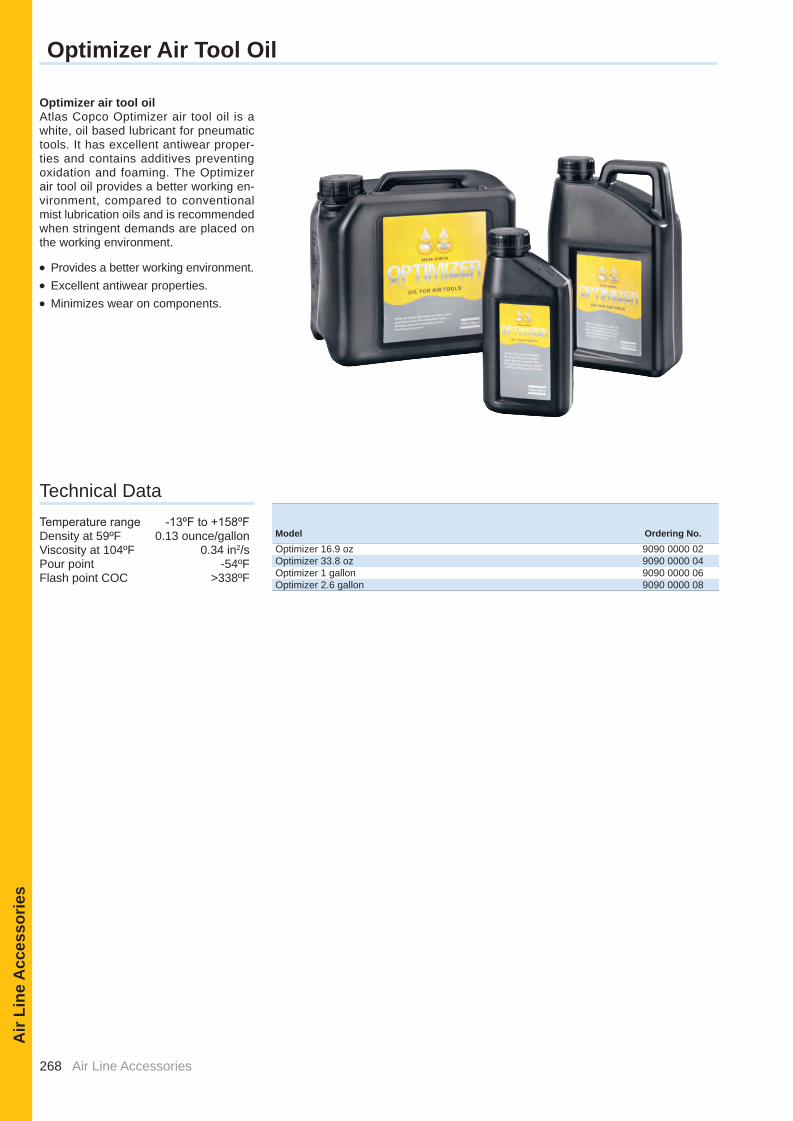
Air
Line
Acc
esso
ries
268 Air Line Accessories
Optimizer Air Tool Oil
Optimizer air tool oilAtlas Copco Optimizer air tool oil is a white, oil based lubricant for pneumatic tools. It has excellent antiwear proper-ties and contains additives preventing oxidation and foaming. The Optimizer air tool oil provides a better working en-vironment, compared to conventional mist lubrication oils and is recommended when stringent demands are placed on the working environment.
l Provides a better working environment.l Excellent antiwear properties.l Minimizes wear on components.
Model Ordering No.Optimizer 16.9 oz 9090 0000 02Optimizer 33.8 oz 9090 0000 04Optimizer 1 gallon 9090 0000 06Optimizer 2.6 gallon 9090 0000 08
Technical DataTemperature range -13ºF to +158ºFDensity at 59ºF 0.13 ounce/gallonViscosity at 104ºF 0.34 in2/sPour point -54ºFFlash point COC >338ºF
Am_AirLineAccessories.indd 268 2012-02-08 14:18:45
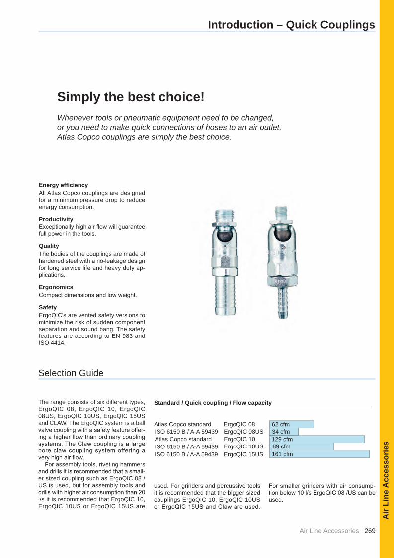
Air
Line
Acc
esso
ries
Air Line Accessories 269
Standard / Quick coupling / Flow capacity
Atlas Copco standard 62 cfmErgoQIC 08ISO 6150 B / A-A 59439 34 cfmErgoQIC 08USAtlas Copco standard 129 cfmErgoQIC 10ISO 6150 B / A-A 59439 89 cfmErgoQIC 10USISO 6150 B / A-A 59439 161 cfmErgoQIC 15US
Introduction – Quick Couplings
Energy effi ciencyAll Atlas Copco couplings are designed for a minimum pressure drop to reduce energy consumption.
ProductivityExceptionally high air fl ow will guarantee full power in the tools.
QualityThe bodies of the couplings are made of hardened steel with a no-leakage design for long service life and heavy duty ap-plications.
ErgonomicsCompact dimensions and low weight.
SafetyErgoQIC's are vented safety versions to minimize the risk of sudden component separation and sound bang. The safety features are according to EN 983 and ISO 4414.
Whenever tools or pneumatic equipment need to be changed, or you need to make quick connections of hoses to an air outlet, Atlas Copco couplings are simply the best choice.
Simply the best choice!
The range consists of six different types, ErgoQIC 08, ErgoQIC 10, ErgoQIC 08US, ErgoQIC 10US, ErgoQIC 15US and CLAW. The ErgoQIC system is a ball valve coupling with a safety feature offer-ing a higher fl ow than ordinary coupling systems. The Claw coupling is a large bore claw coupling system offering a very high air fl ow.
For assembly tools, riveting hammers and drills it is recommended that a small-er sized coupling such as ErgoQIC 08 /US is used, but for assembly tools and drills with higher air consumption than 20 l/s it is recommended that ErgoQIC 10, ErgoQIC 10US or ErgoQIC 15US are
used. For grinders and percussive tools it is recommended that the bigger sized couplings ErgoQIC 10, ErgoQIC 10US or ErgoQIC 15US and Claw are used.
For smaller grinders with air consump-tion below 10 l/s ErgoQIC 08 /US can be used.
Selection Guide
Am_AirLineAccessories.indd 269 2012-02-12 20:32:59
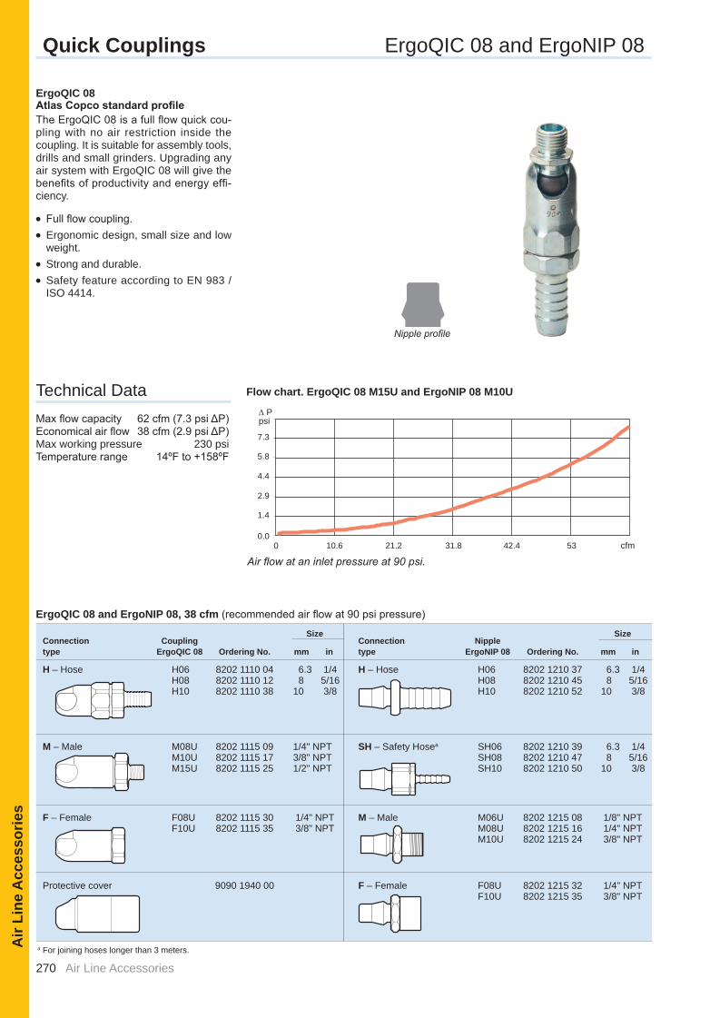
Air
Line
Acc
esso
ries
270 Air Line Accessories
cfm0.0
1.4
2.9
4.4
5.8
7.3
0 10.6 21.2 31.8 42.4 53
∆ Ppsi
Quick Couplings ErgoQIC 08 and ErgoNIP 08
ErgoQIC 08Atlas Copco standard profi leThe ErgoQIC 08 is a full fl ow quick cou-pling with no air restriction inside the coupling. It is suitable for assembly tools, drills and small grinders. Upgrading any air system with ErgoQIC 08 will give the benefi ts of productivity and energy effi -ciency.
l Full fl ow coupling.l Ergonomic design, small size and low
weight.l Strong and durable.l Safety feature according to EN 983 /
ISO 4414.
Technical DataMax fl ow capacity 62 cfm (7.3 psi ΔP)Economical air fl ow 38 cfm (2.9 psi ΔP)Max working pressure 230 psiTemperature range 14ºF to +158ºF
ErgoQIC 08 and ErgoNIP 08, 38 cfm (recommended air fl ow at 90 psi pressure)
Size SizeConnection Coupling Connection Nipple type ErgoQIC 08 Ordering No. mm in type ErgoNIP 08 Ordering No. mm in
H – Hose H06 8202 1110 04 6.3 1/4 H – Hose H06 8202 1210 37 6.3 1/4 H08 8202 1110 12 8 5/16 H08 8202 1210 45 8 5/16 H10 8202 1110 38 10 3/8 H10 8202 1210 52 10 3/8
M – Male M08U 8202 1115 09 1/4" NPT SH – Safety Hosea SH06 8202 1210 39 6.3 1/4 M10U 8202 1115 17 3/8" NPT SH08 8202 1210 47 8 5/16 M15U 8202 1115 25 1/2" NPT SH10 8202 1210 50 10 3/8
F – Female F08U 8202 1115 30 1/4" NPT M – Male M06U 8202 1215 08 1/8" NPT F10U 8202 1115 35 3/8" NPT M08U 8202 1215 16 1/4" NPT M10U 8202 1215 24 3/8" NPT
Protective cover 9090 1940 00 F – Female F08U 8202 1215 32 1/4" NPT F10U 8202 1215 35 3/8" NPT
Flow chart. ErgoQIC 08 M15U and ErgoNIP 08 M10U
Air fl ow at an inlet pressure at 90 psi.
a For joining hoses longer than 3 meters.
Nipple profi le
Am_AirLineAccessories.indd 270 2012-02-08 14:20:15
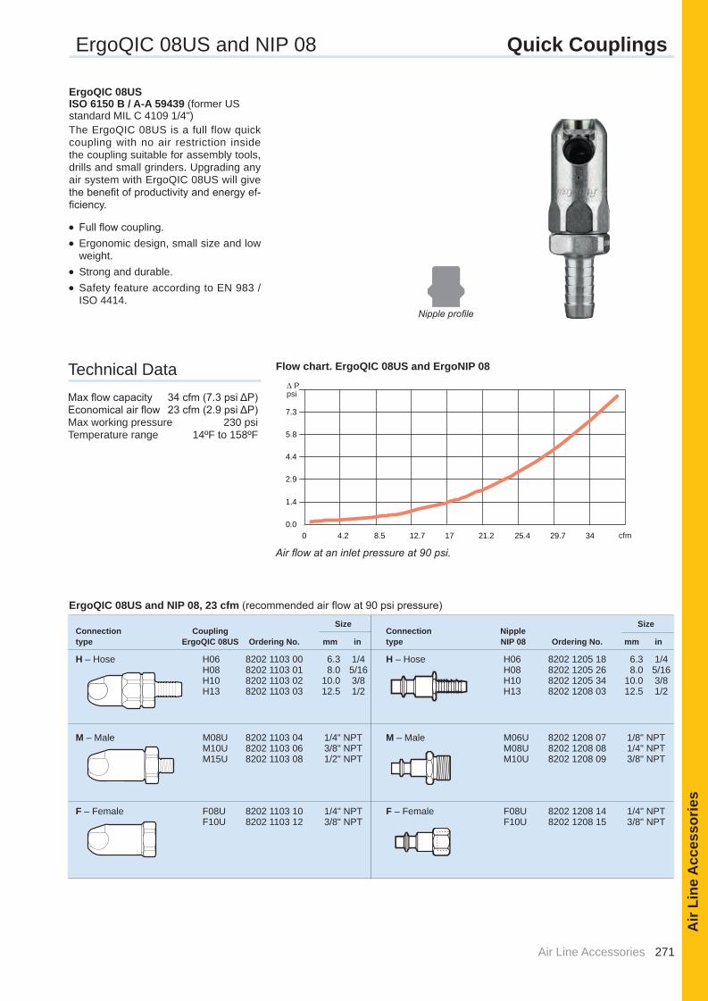
Air
Line
Acc
esso
ries
Air Line Accessories 271
ErgoQIC 08US and NIP 08, 23 cfm (recommended air fl ow at 90 psi pressure)
∆ Ppsi
cfm0.0
1.4
2.9
4.4
5.8
7.3
0 4.2 8.5 12.7 17 21.2 25.4 29.7 34
Size SizeConnection Coupling Connection Nipple type ErgoQIC 08US Ordering No. mm in type NIP 08 Ordering No. mm in
H – Hose H06 8202 1103 00 6.3 1/4 H – Hose H06 8202 1205 18 6.3 1/4 H08 8202 1103 01 8.0 5/16 H08 8202 1205 26 8.0 5/16 H10 8202 1103 02 10.0 3/8 H10 8202 1205 34 10.0 3/8 H13 8202 1103 03 12.5 1/2 H13 8202 1208 03 12.5 1/2
M – Male M08U 8202 1103 04 1/4" NPT M – Male M06U 8202 1208 07 1/8" NPT M10U 8202 1103 06 3/8" NPT M08U 8202 1208 08 1/4" NPT M15U 8202 1103 08 1/2" NPT M10U 8202 1208 09 3/8" NPT
F – Female F08U 8202 1103 10 1/4" NPT F – Female F08U 8202 1208 14 1/4" NPT F10U 8202 1103 12 3/8" NPT F10U 8202 1208 15 3/8" NPT
ErgoQIC 08USISO 6150 B / A-A 59439 (former US standard MIL C 4109 1/4") The ErgoQIC 08US is a full flow quick coupling with no air restriction inside the coupling suitable for assembly tools, drills and small grinders. Upgrading any air system with ErgoQIC 08US will give the benefi t of productivity and energy ef-fi ciency.
l Full fl ow coupling.l Ergonomic design, small size and low
weight.l Strong and durable.l Safety feature according to EN 983 /
ISO 4414.
ErgoQIC 08US and NIP 08 Quick Couplings
Flow chart. ErgoQIC 08US and ErgoNIP 08
Air fl ow at an inlet pressure at 90 psi.
Nipple profi le
Technical DataMax fl ow capacity 34 cfm (7.3 psi ΔP)Economical air fl ow 23 cfm (2.9 psi ΔP)Max working pressure 230 psiTemperature range 14ºF to 158ºF
Am_AirLineAccessories.indd 271 2012-02-08 14:23:24
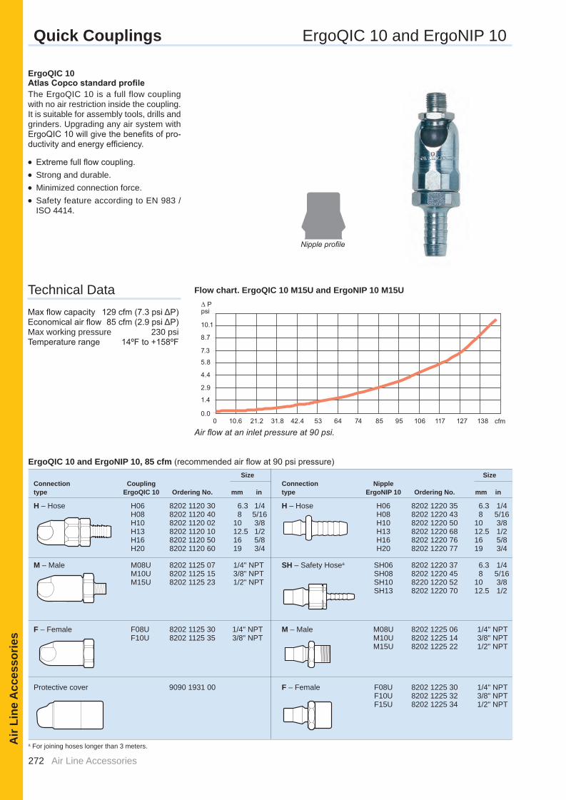
Air
Line
Acc
esso
ries
272 Air Line Accessories
cfm0 10.6 21.2 31.8 42.4 53 64 74 85 95 106 117 127 138
10.1
8.7
7.3
5.8
4.4
2.9
1.4
0.0
psi
Quick Couplings ErgoQIC 10 and ErgoNIP 10
ErgoQIC 10Atlas Copco standard profi leThe ErgoQIC 10 is a full flow coupling with no air restriction inside the coupling. It is suitable for assembly tools, drills and grinders. Upgrading any air system with ErgoQIC 10 will give the benefi ts of pro-ductivity and energy effi ciency.
l Extreme full fl ow coupling.l Strong and durable.l Minimized connection force.l Safety feature according to EN 983 /
ISO 4414.
Technical DataMax fl ow capacity 129 cfm (7.3 psi ΔP)Economical air fl ow 85 cfm (2.9 psi ΔP)Max working pressure 230 psiTemperature range 14ºF to +158ºF
ErgoQIC 10 and ErgoNIP 10, 85 cfm (recommended air fl ow at 90 psi pressure) Size SizeConnection Coupling Connection Nipple type ErgoQIC 10 Ordering No. mm in type ErgoNIP 10 Ordering No. mm in
H – Hose H06 8202 1120 30 6.3 1/4 H – Hose H06 8202 1220 35 6.3 1/4 H08 8202 1120 40 8 5/16 H08 8202 1220 43 8 5/16 H10 8202 1120 02 10 3/8 H10 8202 1220 50 10 3/8 H13 8202 1120 10 12.5 1/2 H13 8202 1220 68 12.5 1/2 H16 8202 1120 50 16 5/8 H16 8202 1220 76 16 5/8 H20 8202 1120 60 19 3/4 H20 8202 1220 77 19 3/4
M – Male M08U 8202 1125 07 1/4" NPT SH – Safety Hosea SH06 8202 1220 37 6.3 1/4 M10U 8202 1125 15 3/8" NPT SH08 8202 1220 45 8 5/16 M15U 8202 1125 23 1/2" NPT SH10 8220 1220 52 10 3/8 SH13 8202 1220 70 12.5 1/2
F – Female F08U 8202 1125 30 1/4" NPT M – Male M08U 8202 1225 06 1/4" NPT F10U 8202 1125 35 3/8" NPT M10U 8202 1225 14 3/8" NPT M15U 8202 1225 22 1/2" NPT
Protective cover 9090 1931 00 F – Female F08U 8202 1225 30 1/4" NPT F10U 8202 1225 32 3/8" NPT F15U 8202 1225 34 1/2" NPT
Flow chart. ErgoQIC 10 M15U and ErgoNIP 10 M15U
Air fl ow at an inlet pressure at 90 psi.
a For joining hoses longer than 3 meters.
Nipple profi le
Am_AirLineAccessories.indd 272 2012-02-08 14:23:55
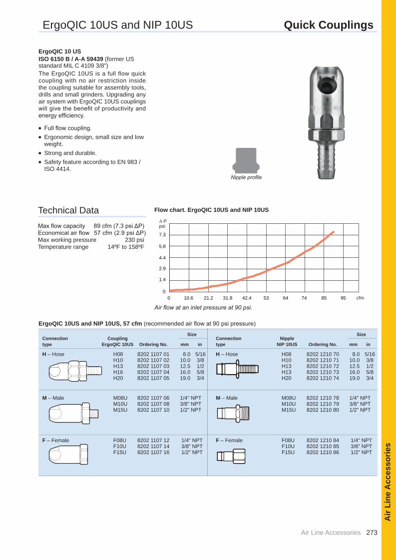
Air
Line
Acc
esso
ries
Air Line Accessories 273
0
1.4
2.9
4.4
5.8
7.3
0 10.6 21.2 31.8 42.4 53 64 74 85 95
∆ Ppsi
cfm
Size SizeConnection Coupling Connection Nipple type ErgoQIC 10US Ordering No. mm in type NIP 10US Ordering No. mm in
H – Hose H08 8202 1107 01 8.0 5/16 H – Hose H08 8202 1210 70 8.0 5/16 H10 8202 1107 02 10.0 3/8 H10 8202 1210 71 10.0 3/8 H13 8202 1107 03 12.5 1/2 H13 8202 1210 72 12.5 1/2 H16 8202 1107 04 16.0 5/8 H13 8202 1210 73 16.0 5/8 H20 8202 1107 05 19.0 3/4 H20 8202 1210 74 19.0 3/4
M – Male M08U 8202 1107 06 1/4" NPT M – Male M08U 8202 1210 78 1/4" NPT M10U 8202 1107 08 3/8" NPT M10U 8202 1210 79 3/8" NPT M15U 8202 1107 10 1/2" NPT M15U 8202 1210 80 1/2" NPT
F – Female F08U 8202 1107 12 1/4" NPT F – Female F08U 8202 1210 84 1/4" NPT F10U 8202 1107 14 3/8" NPT F10U 8202 1210 85 3/8" NPT F15U 8202 1107 16 1/2" NPT F15U 8202 1210 86 1/2" NPT
ErgoQIC 10US and NIP 10US, 57 cfm (recommended air fl ow at 90 psi pressure)
ErgoQIC 10 USISO 6150 B / A-A 59439 (former US standard MIL C 4109 3/8")The ErgoQIC 10US is a full flow quick coupling with no air restriction inside the coupling suitable for assembly tools, drills and small grinders. Upgrading any air system with ErgoQIC 10US couplings will give the benefi t of productivity and energy effi ciency.
l Full fl ow coupling.l Ergonomic design, small size and low
weight.l Strong and durable.l Safety feature according to EN 983 /
ISO 4414.
ErgoQIC 10US and NIP 10US Quick Couplings
Flow chart. ErgoQIC 10US and NIP 10US
Air fl ow at an inlet pressure at 90 psi.
Nipple profi le
Technical DataMax fl ow capacity 89 cfm (7.3 psi ΔP)Economical air fl ow 57 cfm (2.9 psi ΔP)Max working pressure 230 psiTemperature range 14ºF to 158ºF
Am_AirLineAccessories.indd 273 2012-02-08 14:27:41
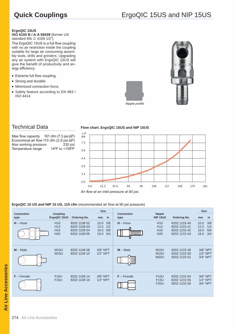
Air
Line
Acc
esso
ries
274 Air Line Accessories
cfm0.0
1.4
2.9
4.4
5.8
7.3
0.0 21.2 42.4 64 85 106 127 148 170
∆psi
P
Quick Couplings ErgoQIC 15US and NIP 15US
ErgoQIC 15USISO 6150 B / A-A 59439 (former US standard MIL C 4109 1/2")The ErgoQIC 15US is a full fl ow coupling with no air restriction inside the coupling suitable for large air consuming assem-bly tools, drills and grinders. Upgrading any air system with ErgoQIC 15US will give the benefi t of productivity and en-ergy effi ciency.
l Extreme full fl ow coupling.l Strong and durable.l Minimized connection force.l Safety feature according to EN 983 /
ISO 4414.
Technical DataMax fl ow capacity 161 cfm (7.3 psi ΔP)Economical air fl ow 110 cfm (2.9 psi ΔP)Max working pressure 230 psiTemperature range 14ºF to +158ºF
ErgoQIC 15 US and NIP 15 US, 110 cfm (recommended air fl ow at 90 psi pressure)
Size SizeConnection Coupling Connection Nipple type ErgoQIC 15US Ordering No. mm in type NIP 15US Ordering No. mm in
H – Hose H10 8202 1108 02 10.0 3/8 H – Hose H10 8202 1215 40 10.0 3/8 H13 8202 1108 03 12.5 1/2 H13 8202 1215 41 12.5 1/2 H16 8202 1108 04 16.0 5/8 H16 8202 1215 42 16.0 5/8 H20 8202 1108 05 19.0 3/4 H20 8202 1215 43 19.0 3/4
M – Male M10U 8202 1108 08 3/8" NPT M – Male M10U 8202 1215 49 3/8" NPT M15U 8202 1108 10 1/2" NPT M15U 8202 1215 50 1/2" NPT M20U 8202 1215 51 3/4" NPT
F – Female F10U 8202 1108 14 3/8" NPT F – Female F10U 8202 1215 54 3/8" NPT F15U 8202 1108 16 1/2" NPT F15U 8202 1215 55 1/2" NPT F20U 8202 1215 56 3/4" NPT
Flow chart. ErgoQIC 15US and NIP 15US
Air fl ow at an inlet pressure at 90 psi.
Nipple profi le
Am_AirLineAccessories.indd 274 2012-02-08 14:31:23
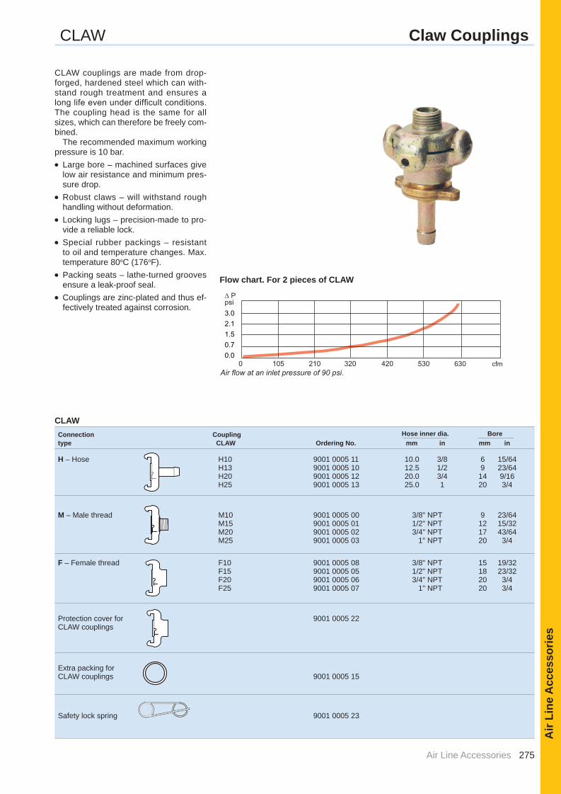
Air
Line
Acc
esso
ries
Air Line Accessories 275
∆ Ppsi
0 105 210 320 420 cfm530 630
3.02.11.50.70.0
CLAW Connection Coupling Hose inner dia. Boretype CLAW Ordering No. mm in mm in
H – Hose H10 9001 0005 11 10.0 3/8 6 15/64 H13 9001 0005 10 12.5 1/2 9 23/64 H20 9001 0005 12 20.0 3/4 14 9/16 H25 9001 0005 13 25.0 1 20 3/4
M – Male thread M10 9001 0005 00 3/8" NPT 9 23/64 M15 9001 0005 01 1/2" NPT 12 15/32 M20 9001 0005 02 3/4" NPT 17 43/64 M25 9001 0005 03 1" NPT 20 3/4
F – Female thread F10 9001 0005 08 3/8" NPT 15 19/32 F15 9001 0005 05 1/2" NPT 18 23/32 F20 9001 0005 06 3/4" NPT 20 3/4 F25 9001 0005 07 1" NPT 20 3/4
Protection cover for 9001 0005 22 CLAW couplings
Extra packing for CLAW couplings 9001 0005 15 Safety lock spring 9001 0005 23
CLAW couplings are made from drop-forged, hardened steel which can with-stand rough treatment and ensures a long life even under difficult conditions. The coupling head is the same for all sizes, which can therefore be freely com-bined.
The recommended maximum working pressure is 10 bar.l Large bore – machined surfaces give
low air resistance and minimum pres-sure drop.
l Robust claws – will withstand rough handling without deformation.
l Locking lugs – precision-made to pro-vide a reliable lock.
l Special rubber packings – resistant to oil and temperature changes. Max. temperature 80oC (176oF).
l Packing seats – lathe-turned grooves ensure a leak-proof seal.
l Couplings are zinc-plated and thus ef-fectively treated against corrosion.
CLAW Claw Couplings
Flow chart. For 2 pieces of CLAW
Air flow at an inlet pressure of 90 psi.
Am_AirLineAccessories.indd 275 2012-02-08 14:32:29
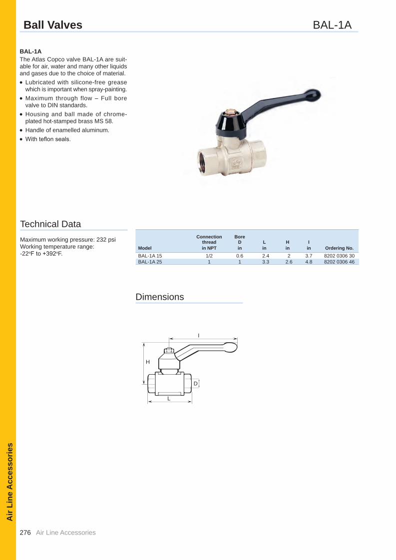
Air
Line
Acc
esso
ries
276 Air Line Accessories
L
H
I
D
BAL-1AThe Atlas Copco valve BAL-1A are suit-able for air, water and many other liquids and gases due to the choice of material.l Lubricated with silicone-free grease
which is important when spray-painting.l Maximum through flow – Full bore
valve to DIN standards.l Housing and ball made of chrome-
plated hot-stamped brass MS 58.l Handle of enamelled aluminum.l With tefl on seals.
Technical DataMaximum working pressure: 232 psiWorking temperature range: -22oF to +392oF.
Ball Valves BAL-1A
Dimensions
Connection Bore thread D L H IModel in NPT in in in in Ordering No.BAL-1A 15 1/2 0.6 2.4 2 3.7 8202 0306 30BAL-1A 25 1 1 3.3 2.6 4.8 8202 0306 46
Am_AirLineAccessories.indd 276 2012-02-08 14:32:43

Air
Line
Acc
esso
ries
Air Line Accessories 277
0.0
1.5
2.9
4.4
5.9
7.3
0.0 10.6 21.2 31.8 42.4 53.0 63.6 74.2 84.8 95.40.00
1.5
2.9
4.4
5.9
7.3
8.8
10.3
11.7
13.2
14.7
16.2
17.6
0 .00 10.6 21.2 31.8 42.4 53.0
0.00
0.50
1.0
1.50
2.0
2.50
3.0
3.50
4.0
4.50
5.0
0 .00 20.0 60.0 80.0 120.0 140.040.0 100.0 160.0
MultiFlex SwivelMulti-directional connectorThe MultiFlex swivel is an ingenious multi-directional connector. Connect your tool and the hose will stay in the ideal position however much you and the tool move around. The MultiFlex bends and rotates 360º in all directions while the hose stays straight. It takes the effort out of working in those cramped spac-es. What’s more, the hose feels almost weightless and it reduces hose wear. It’s the magic of MultiFlex – a marriage of er-gonomic thinking and ingenious design.
l Ergonomic.l Reduces hose wear.l High fl ow capacity.l Minimum pressure drop.l Strong and durable.
MultiFlex Swivel Connectors
a The pressure drop will be 2.9 psi at an inlet pressure of 87 psi.
Max rec. Thread air fl ow a Inlet female Outlet male Weight Length Dia Model l/s cfm in in lb in in Ordering No.MultiFlex 1/8" NPT 12 25 1/8 1/8 0.16 2.6 0.94 8202 1350 25MultiFlex 1/4" NPT 12 25 1/4 1/4 0.16 2.6 0.94 8202 1350 26MultiFlex 3/8" NPT 32 68 3/8 3/8 0.29 3.2 1.16 8202 1350 28MultiFlex 1/2" NPT 32 68 1/2 1/2 0.28 3.2 1.16 8202 1350 30MultiFlex 1/8" NPT b 12 25 1/8 1/8 0.17 2.6 1.06 8202 1350 50MultiFlex 1/4" NPT b 12 25 1/4 1/4 0.17 2.6 1.06 8202 1350 51MultiFlex 1/2" NPT c 54 114 1/2 1/2 0.72 3.87 1.54 8202 1350 62
MultiFlex 1/2" or 3/8" MultiFlex 1/8" or 1/4"
Pre
ssur
e dr
op (p
si)
Pre
ssur
e dr
op (p
si)
Flow (cfm) Flow (cfm)
90 degrees 90 degrees
Flow chart
MultiFlex HIGH FLOW
Pre
ssur
e dr
op (p
si)
Flow (cfm)
90 degrees
b With cover.c High Flow.
Am_AirLineAccessories.indd 277 2012-02-08 14:35:25
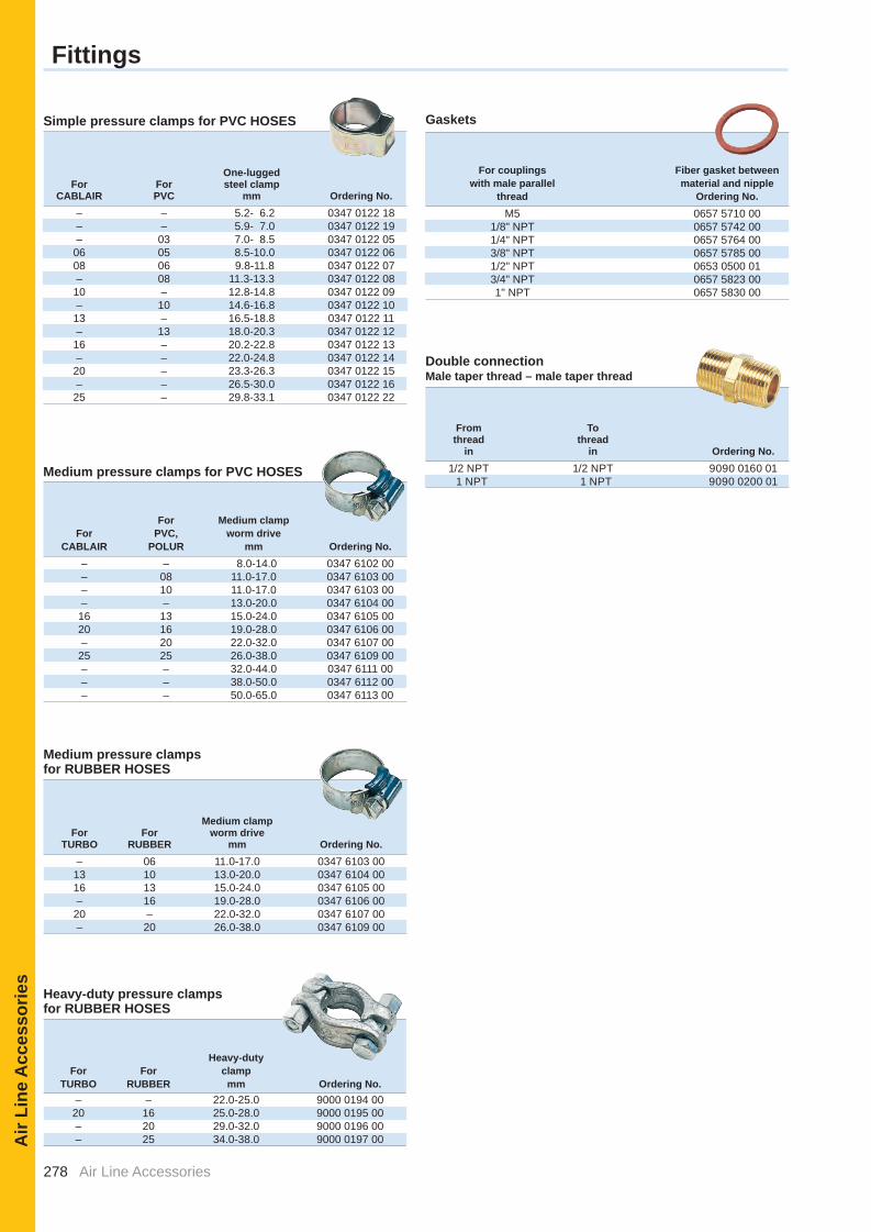
Air
Line
Acc
esso
ries
278 Air Line Accessories
For Medium clamp For PVC, worm drive CABLAIR POLUR mm Ordering No. – – 8.0-14.0 0347 6102 00 – 08 11.0-17.0 0347 6103 00 – 10 11.0-17.0 0347 6103 00 – – 13.0-20.0 0347 6104 00 16 13 15.0-24.0 0347 6105 00 20 16 19.0-28.0 0347 6106 00 – 20 22.0-32.0 0347 6107 00 25 25 26.0-38.0 0347 6109 00 – – 32.0-44.0 0347 6111 00 – – 38.0-50.0 0347 6112 00 – – 50.0-65.0 0347 6113 00
Medium pressure clamps for RUBBER HOSES
Heavy-duty For For clamp TURBO RUBBER mm Ordering No. – – 22.0-25.0 9000 0194 00 20 16 25.0-28.0 9000 0195 00 – 20 29.0-32.0 9000 0196 00 – 25 34.0-38.0 9000 0197 00
Simple pressure clamps for PVC HOSES
One-lugged For For steel clamp CABLAIR PVC mm Ordering No. – – 5.2- 6.2 0347 0122 18 – – 5.9- 7.0 0347 0122 19 – 03 7.0- 8.5 0347 0122 05 06 05 8.5-10.0 0347 0122 06 08 06 9.8-11.8 0347 0122 07 – 08 11.3-13.3 0347 0122 08 10 – 12.8-14.8 0347 0122 09 – 10 14.6-16.8 0347 0122 10 13 – 16.5-18.8 0347 0122 11 – 13 18.0-20.3 0347 0122 12 16 – 20.2-22.8 0347 0122 13 – – 22.0-24.8 0347 0122 14 20 – 23.3-26.3 0347 0122 15 – – 26.5-30.0 0347 0122 16 25 – 29.8-33.1 0347 0122 22
Medium clamp For For worm drive TURBO RUBBER mm Ordering No. – 06 11.0-17.0 0347 6103 00 13 10 13.0-20.0 0347 6104 00 16 13 15.0-24.0 0347 6105 00 – 16 19.0-28.0 0347 6106 00 20 – 22.0-32.0 0347 6107 00 – 20 26.0-38.0 0347 6109 00
Gaskets
For couplings Fiber gasket between with male parallel material and nipple thread Ordering No. M5 0657 5710 00 1/8" NPT 0657 5742 00 1/4" NPT 0657 5764 00 3/8" NPT 0657 5785 00 1/2" NPT 0653 0500 01 3/4" NPT 0657 5823 00 1" NPT 0657 5830 00
Medium pressure clamps for PVC HOSES
Heavy-duty pressure clamps for RUBBER HOSES
Fittings
Double connectionMale taper thread – male taper thread
From To thread thread in in Ordering No. 1/2 NPT 1/2 NPT 9090 0160 01 1 NPT 1 NPT 9090 0200 01
Am_AirLineAccessories.indd 278 2012-02-08 14:37:44
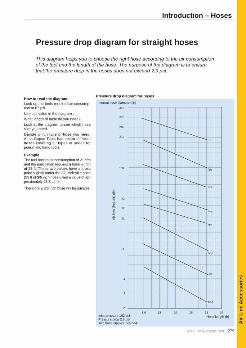
Air
Line
Acc
esso
ries
Air Line Accessories 279
392
318
265
212
106
42
21
11
4
3
2
32
6.6 13 20 26 33 39
1
3/4
5/8
1/2
3/8
5/16
1/4
3/16
How to read the diagram:Look up the tools required air consump-tion at 87 psi.Use this value in the diagram .What length of hose do you need?Look at the diagram to see which hose size you need.Decide which type of hose you need, Atlas Copco Tools has seven different hoses covering all types of needs for pneumatic hand tools.
ExampleThe tool has an air consumption of 21 cfm and the application requires a hose length of 23 ft. These two values have a cross point slightly under the 3/8 inch size hose (23 ft of 3/8 inch hose gives a value of ap-proximately 23.3 cfm).
Therefore a 3/8 inch hose will be suitable.
Introduction – Hoses
This diagram helps you to choose the right hose according to the air consumption of the tool and the length of the hose. The purpose of the diagram is to ensure that the pressure drop in the hoses does not exceed 2.9 psi.
Pressure drop diagram for straight hoses
Air
flow
(fre
e ai
r) c
fm
Pressure drop diagram for hoses Internal hose diameter (in)
Hose length (ft)Inlet pressure 102 psiPressure drop 2.9 psiTwo hose nipples included
Am_AirLineAccessories.indd 279 2012-02-08 14:37:55

Air
Line
Acc
esso
ries
280 Air Line Accessories
a With a safety factor of 3 at 68oF (at the max temp of +140oF the working pressure should be reduced by 50%).b The pressure drop will be 3 psi on a hose length of 16 ft.
Max Weight Hose Hose working Max rec. per inside dia outside dia pressurea air fl owb 101 ft coilModel in in psi cfm lb Ordering No.CABLAIR 06 1/4 7/20 260 9 2.6 9093 0035 11CABLAIR 08 5/16 2/5 260 16 3.7 9093 0035 41CABLAIR 10 3/8 1/2 203 28 4.6 9093 0035 71CABLAIR 13 1/2 13/20 188 45 6.6 9093 0036 01CABLAIR 16 5/8 4/5 160 91 11.9 9093 0036 31CABLAIR 20 3/4 19/20 160 159 12.8 9093 0036 61CABLAIR 25 1 1 1/5 145 265 23 9093 0036 91
Hoses CABLAIR, ESD
CABLAIR hosesSuper-light fl exible PVC-hoseCablair is made of high-strength, high per-formance PVC compound. The Cablair hose weighs 30-50% less and is much softer and more flexible than conven-tional PVC hoses. This ensures com-plete freedom of movement for op-erators of pneumatic hand tools in any working environment.
l Low weight.l Extremely soft and fl exible.l Silicone free.l Ergonomic.l Working temperature -13ºF to +40ºF.
CABLAIR ESDExtra fl exible antistatic air hoseCablair ESD is an extra fl exible antistatic air hose designed specifically for use within the computer manufacturing in-dustry. The hose possesses properties which enable ESDS (electrostatic sensi-tive devices) to be handled in a protected area with a low risk level, as a result of electrostatic discharge. In addition to a known demand in the computer industry, it is expected that potential exists in the electronics, radio and communication fields. The connection device must be earthed/grounded.
l Extra fl exible.l Antistatic.l Silicone free.l Testing in accordance with BS2050:1978 (1998) 4.12.l Working temperature +5ºF to +140ºF.
Max Weight Hose Hose working Max rec. per inside dia outside dia pressurea air fl ow 101 ft coilModel in in psi cfm lb Ordering No.CABLAIR ESD 06 1/4 7/16 145 9 5 8202 0501 06CABLAIR ESD 08 5/16 1/2 130 16 5.6 8202 0501 08CABLAIR ESD 10 3/8 9/16 116 28 6 8202 0501 10CABLAIR ESD 13 1/2 23/32 101 45 9.7 8202 0501 13
a With a safety factor of 3 at 68oF (at the max temp of +140oF the working pressure should be reduced by 50%).
Am_AirLineAccessories.indd 280 2012-02-08 14:41:56
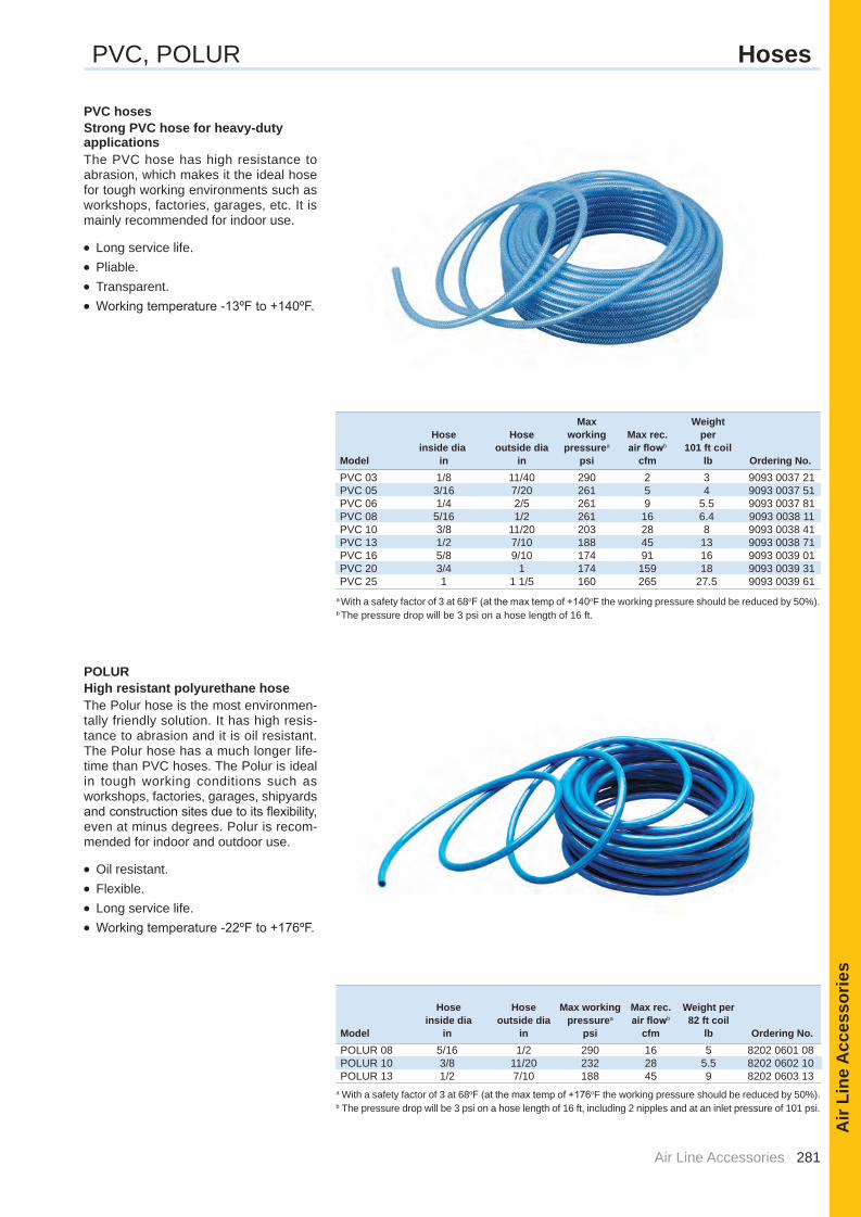
Air
Line
Acc
esso
ries
Air Line Accessories 281
Max Weight Hose Hose working Max rec. per inside dia outside dia pressurea air fl owb 101 ft coilModel in in psi cfm lb Ordering No.PVC 03 1/8 11/40 290 2 3 9093 0037 21PVC 05 3/16 7/20 261 5 4 9093 0037 51PVC 06 1/4 2/5 261 9 5.5 9093 0037 81PVC 08 5/16 1/2 261 16 6.4 9093 0038 11PVC 10 3/8 11/20 203 28 8 9093 0038 41PVC 13 1/2 7/10 188 45 13 9093 0038 71PVC 16 5/8 9/10 174 91 16 9093 0039 01PVC 20 3/4 1 174 159 18 9093 0039 31PVC 25 1 1 1/5 160 265 27.5 9093 0039 61
PVC hosesStrong PVC hose for heavy-duty applicationsThe PVC hose has high resistance to abrasion, which makes it the ideal hose for tough working environments such as workshops, factories, garages, etc. It is mainly recommended for indoor use.
l Long service life.l Pliable.l Transparent.l Working temperature -13ºF to +140ºF.
PVC, POLUR Hoses
POLURHigh resistant polyurethane hoseThe Polur hose is the most environmen-tally friendly solution. It has high resis-tance to abrasion and it is oil resistant. The Polur hose has a much longer life-time than PVC hoses. The Polur is ideal in tough working conditions such as workshops, factories, garages, shipyards and construction sites due to its fl exibility, even at minus degrees. Polur is recom-mended for indoor and outdoor use.
l Oil resistant.l Flexible.l Long service life.l Working temperature -22ºF to +176ºF.
Hose Hose Max working Max rec. Weight per inside dia outside dia pressurea air fl owb 82 ft coilModel in in psi cfm lb Ordering No.POLUR 08 5/16 1/2 290 16 5 8202 0601 08 POLUR 10 3/8 11/20 232 28 5.5 8202 0602 10 POLUR 13 1/2 7/10 188 45 9 8202 0603 13
a With a safety factor of 3 at 68oF (at the max temp of +176oF the working pressure should be reduced by 50%).b The pressure drop will be 3 psi on a hose length of 16 ft, including 2 nipples and at an inlet pressure of 101 psi.
a With a safety factor of 3 at 68oF (at the max temp of +140oF the working pressure should be reduced by 50%).b The pressure drop will be 3 psi on a hose length of 16 ft.
Am_AirLineAccessories.indd 281 2012-02-08 14:42:32

Air
Line
Acc
esso
ries
282 Air Line Accessories
Max Weight Hose Hose working Max rec. per inside dia outside dia pressure a air fl ow b 65 ft coilModel in in psi cfm lb Ordering No.TURBO 13 1/2 3/4 232 45 8.5 9093 0057 91TURBO 16 5/8 9/10 232 91 10.5 9093 0057 31TURBO 20 3/4 1 232 159 12 9093 0057 61
a With a safety factor of 4 at 68°F.b The pressure drop will be 3 psi on a hose length of 16 ft, including 2 nipples and at an inlet pressure of 101 psi.
Hoses TURBO, RUBBER
TURBOSuper-light fl exible rubber hose The Turbo hose has been developed for fl exible use both indoor and outdoor. The hose weighs 30-40% less than conven-tional rubber hoses, making it ideal for foundries, shipyards, engineering work-shops and construction sites. The Turbo hose is oil resistant.
l Extremely low weight.l Soft and fl exible.l Antistatic.l Grinding and welding spatter resistant.l Working temperature -40ºF to +194ºF.
a With a safety factor of 5 at 68oF.b The pressure drop will be 3 psi on a hose length of 16 ft, including 2 nipples and at an inlet pressure of 101 psi.
RUBBERDurable reinforced heavy duty rubber hoseThe hose withstands rough handling and is suitable for the most demanding tasks in construction, mining, shipyards, foundries etc. The inner lining is black EPDM rubber, conductive to dissipate static electricity. Reinforcement with high tensile strength made of syntetic textile yarns.
l Durable.l Antistatic.l Grinding and welding spatter resistant.l Working temperature -40ºF to +194ºF.
Max Hose Hose working Max rec. inside dia outside dia pressure a air fl ow b Length WeightModel in in psi cfm ft lb Ordering No.RUBBER 06 1/4 1/2 232 9 98 7.7 9030 2036 00RUBBER 10 3/8 2/3 232 27 98 15.2 9030 2037 00RUBBER 13 1/2 5/8 232 44 98 27.1 9030 2038 00RUBBER 16 5/8 3/4 232 91 98 30.6 9030 2039 00RUBBER 20 3/4 1 1/5 232 159 98 42.5 9030 2040 00RUBBER 20 3/4 1 1/5 232 159 65 28.4 9030 2040 03RUBBER 25 1 1 1/2 232 265 98 52.9 9030 2041 00RUBBER 25 1 1 1/2 232 265 65 32.3 9030 2041 03
Am_AirLineAccessories.indd 282 2012-02-08 14:44:18

Air
Line
Acc
esso
ries
Air Line Accessories 283
Max Weight Hose Hose working Max rec. per inside dia outside dia pressure a air fl ow b 65 ft coilModel in in psi cfm lb Ordering No.RUBAIR 10 3/8 5/8 232 27 7.9 8202 0402 10RUBAIR 13 1/2 3/4 232 44 10.4 8202 0403 13RUBAIR 16 5/8 1 232 91 13.5 8202 0404 16RUBAIR 20 3/4 1 232 159 17.2 8202 0405 20RUBAIR 25 1 1 1/3 232 265 26.0 8202 0406 25
a With a safety factor of 5 at 68°F.b The pressure drop will be 3 psi on a hose length of 16 ft, including 2 nipples and at an inlet pressure of 101 psi.
RUBAIRDurable reinforced heavy duty rubber hose The Rubair hose is double reinforced to fulfi l all general heavy duty demands and is recommended for indoor and outdoor use. The Rubair hose is oil resistant.
l Durable.l Antistatic.l Grinding and welding spatter resistant.l Working temperature -40ºF to +194ºF.
RUBAIR Hoses
Am_AirLineAccessories.indd 283 2012-02-08 14:44:36

Air
Line
Acc
esso
ries
284 Air Line Accessories
D
CA B
Max Hose Hose Max. spiral Male inside outside rec. Working
Length dia threads
dia dia air flow a range (A) (B) (C) (D) in Model in in cfm ft in in in ft NPT Ordering No.SPI 1SPSW-M 1/4 3/8 10 13 19 1/2 13 6 2 1/4 8202 0508 91SPI 2SPSW-M 5/16 1/2 21 13 19 1/2 10 1/2 6 2 3/4 3/8 8202 0508 92SPI 2SPSW-L 5/16 1/2 19 20 19 1/2 17 6 2 3/4 3/8 8202 0508 93SPI 2SPSW-XL 5/16 1/2 13 26 19 1/2 23 1/2 6 2 3/4 3/8 8202 0508 94SPI 3SP-M 7/16 5/8 47 13 19 1/2 10 6 4 3/8 8202 0508 95SPI 3SP-L 7/16 5/8 36 20 19 1/2 15 1/2 6 4 3/8 8202 0508 96SPI 3SP-XL 7/16 5/8 28 26 19 1/2 21 1/2 6 4 3/8 8202 0508 97SPI 4SP-L 1/2 3/4 57 20 19 1/2 40 1/3 6 4 1/2 1/2 8202 0508 98SPI 4SP-XXL 1/2 3/4 45 33 19 1/2 33 1/2 20 4 1/2 1/2 8202 0508 99
a At inlet pressure 87 psi and pressure drop 7 psi.Teflon coating on NPT threads.
Spiral Hoses SPI
Dimensions
SPIElastic hose for vertical and horizontal applicationsSPI elastic spiral hose is ideal for air tools used at varying distances from a fixed air outlet. It is easily stretched and retracts immediately when released.When used with hand tools, its self-storage principle ensures that the hose is kept off the floor and out of the way of the operator. The SPI 1 and SPI 2 have ball bearing swiv-els fitted on the long hose side to allow 360º rotation. All spiral hoses, except the SPI4, are fitted with plastic spring guard. SPI is the ideal hose in combina-tion with a balancer.
l Self-retractable.l Light and flexible.l Strong and durable.l Tubing material: Polyurethane (100%
PUR).l Hardness: Shore A 98 +2.l Colour: Blue.l Working pressure: 116 psi at 73ºF.l Burst pressure: 363 psi at 73ºF.l Temperature range: -40ºF to +158ºF.
Am_AirLineAccessories.indd 284 2012-02-08 14:46:29

Air
Line
Acc
esso
ries
Air Line Accessories 285
NOTE: Tool nipple is not included in the Productivity kit and needs to be order separately together with the tool.
NOTE: Tool nipple is not included in the Productivity kit and needs to be order separately together with the tool.
Productivity Kits
Productivity kits boost productivity, ex-tend tool lifetime and ensure minimum pressure drop.
Each productivity kit includes ball valve, air preparation unit, and the cou-plings, hose and nipples needed for cor-rect and safe installation of the tool.
Just choose the correct productivity kit based on the air flow requirement of the tool and whether the tool needs lu-brication or not. You’ll be surprised how much the productivity kit improves the performance of the tool.
l Improves the performance of the tool.l Fast and easy installation.l Extends tool lifetime.
Model Max air flow Hose 16.4 ft Coupling Lubrication Ordering No.For small screwdrivers and small drills MIDI Optimizer F/R EQ08US-C06 12 cfm Cablair 06 ErgoQIC 08US No 8202 0850 21MIDI Optimizer F/RD EQ08US-C06 19 cfm Cablair 06 ErgoQIC 08US Yes 8202 0850 22 For screwdrivers and drills MIDI Optimizer F/RD EQ08US-C08 19 cfm Cablair 08 ErgoQIC 08US Yes 8202 0850 23MIDI Optimizer F/R EQ08US-C08 19 cfm Cablair 08 ErgoQIC 08US No 8202 0850 24 For 1/2" drills and small nutrunners MIDI Optimizer F/RD EQ10US-C10 34 cfm Cablair 10 ErgoQIC 10US Yes 8202 0850 25MIDI Optimizer F/RD EQ10US-R10 34 cfm Rubber 10 ErgoQIC 10US Yes 8202 0850 26 For drills and nutrunners MIDI Optimizer F/RD EQ10US-C13 50 cfm Cablair 13 ErgoQIC 10US Yes 8202 0850 27MIDI Optimizer F/RD EQ10US-R13 50 cfm Rubber 13 ErgoQIC 10US Yes 8202 0850 28 For grinders, percussive tools and nutrunners MIDI Optimizer F/RD EQ10US-T13 65 cfm Turbo 13 ErgoQIC 10US Yes 8202 0850 29MIDI Optimizer F/R EQ10US-T13 65 cfm Turbo 13 ErgoQIC 10US No 8202 0850 30 For large ginders MIDI Optimizer F/RD EQ15US-T16 85 cfm Turbo 16 ErgoQIC 15US Yes 8202 0850 31MAXI F/R EQ15US-T20 140 cfm Turbo 20 ErgoQIC 15US No 8202 0850 32MAXI F/RD EQ15US-T20 140 cfm Turbo 20 ErgoQIC 15US Yes 8202 0850 33
Productivity kits for impact wrenches and pulse tools
Productivity kits for screwdrivers, drills and grinders
Model Max air flow Hose 16.4 ft Coupling Lubrication Ordering No.For small impact wrenches and pulse toolsMIDI Optimizer F/RD EP EQ08US-C08 19 cfm Cablair 08 ErgoQIC 08US Yes 8202 0850 45 For 1/2" impact wrenches and pulse tools MIDI Optimizer F/RD EP EQQ10US-C10 34 cfm Cablair 10 ErgoQIC 10US Yes 8202 0850 46 For impact wrenches and pulse toolsMIDI Optimizer F/RD EP EQ10US-C13 50 cfm Cablair 13 ErgoQIC 10US Yes 8202 0850 47MIDI Optimizer F/RD EP EQ10US-T13 65 cfm Turbo 13 ErgoQIC 10US Yes 8202 0850 48
Am_AirLineAccessories.indd 285 2012-02-08 14:55:37

Air
Line
Acc
esso
ries
286 Air Line Accessories
Pre-mounted Hose Kits
Pre-mounted hose kitsAtlas Copco hose kits provides an easy way to choose the right hose and cou-pling combination for pneumatic tools. Each kit is ready for immediate use with-out the need of assembly tools.l Correct combination hose – coupling.l Leak free hose connections.l Immediate use.
Dia Length Air inlet thread Hose in ft Nipple Coupling nipple, NPT Ordering No.Cablair 1/4 16 ErgoNIP 08 ErgoQIC 08 - 8202 1182 01Cablair 1/4 16 NIP 08 ErgoQIC 08US - 8202 1182 16Cablair 5/16 16 NIP 08 ErgoQIC 08US - 8202 1182 21Cablair 3/8 5 ErgoNIP 10 ErgoQIC 10 - 8202 1182 25Cablair 3/8 16 ErgoNIP 10 ErgoQIC 10 - 8202 1182 05Cablair 3/8 16 ErgoNIP 10 ErgoQIC 08 1/4 8202 1180 10Cablair 3/8 16 NIP 10US ErgoQIC 10US - 8202 1182 17Cablair 3/8 32 ErgoNIP 10 ErgoQUC 08 1/4 8202 1180 13Cablair 1/2 16 ErgoNIP 10 ErgoQIC 10 - 8202 1182 10Cablair 1/2 16 ErgoNIP 10 ErgoQIC 08 1/4 8202 1180 11Cablair 1/2 16 ErgoNIP 10 ErgoQIC 10 3/8 8202 1180 12Cablair 1/2 16 NIP 10US ErgoQIC 10US - 8202 1182 18Cablair 1/2 28 ErgoNIP 10 ErgoQIC 10 - 8202 1182 20Cablair 1/2 32 ErgoNIP 10 ErgoQIC 10 - 8202 1182 15Cablair 1/2 32 ErgoNIP 10 ErgoQIC 08 1/4 8202 1180 14Cablair 1/2 32 ErgoNIP 10 ErgoQIC 10 3/8 8202 1180 15Rubber 3/8 16 NIP 10US ErgoQIC 10US - 8202 1182 23Rubber 1/2 16 NIP 10US ErgoQIC 10US - 8202 1182 24Turbo 1/2 16 NIP 10US ErgoQIC 10US - 8202 1182 19Turbo 5/8 16 ErgoNIP 10 ErgoQIC 10 - 8202 1180 34Turbo 5/8 16 NIP 15US ErgoQIC 15US - 8202 1182 22Turbo 5/8 32 ErgoNIP 10 ErgoQIC 10 - 8202 1180 46
Hose kits
Am_AirLineAccessories.indd 286 2012-02-08 14:57:12

Air
Line
Acc
esso
ries
Air Line Accessories 287
8.5
15.5
1.2
0.1-Ø0.49
2.62.6
0.40.7
1.3
0.7
8.2
0.4
13.4
7.4
14.8
Connection Air fl ow Hose distribution (at 14 psi Length inside dia hose pressure drop) Weight Model ft mm in NPT cfm kg lb Ordering No.HM FLEX Grinding 25 8 5/16 1/4" male thread 15 8.5 19 8202 1181 07HM FLEX 30 10 3/8 1/4" male thread 25 8.5 19 8202 1181 06
Connection Air fl ow Hose distribution (at 14 psi Length inside dia hose pressure drop) Weight Model ft mm in NPT cfm kg lb Ordering No.HM LIGHT 30 8 5/16 1/4" male thread 15 4.5 10 8202 1180 96HM LIGHT 25 8 5/16 1/4" male thread 15 4.5 10 8202 1180 98
HM LIGHTThe HM Light has a composite casing and a highly wear and oil resistant PUR hose. The HM Light hose reel is recom-mended for small screwdrivers and small pulse tools.
� Revolving hinge for fl exible use.� Light and compact.� Kink resistant PUR-hose.� Working temperature: -22°F - +140°F.� Max working pressure is 290 psi.� Inlet hose length: 3 ft.
HM FLEXThe HM FLEX has a high quality, com-pact steel casing and is recommended for small and medium screwdrivers, small and medium pulse tools, small drills, im-pact wrenches up to 1/2" size, small grind-ers and riveting and chipping hammers.
� HM FLEX Grinding with spatter resis-tant rubber hose.
� Revolving hinge for fl exible use.� Strong and durable.� Working temperature: -22°F - +140°F.� Max working pressure: 290 psi.� Inlet hose length: 5 ft.
HM Light, HM Flex Hose Reels
Dimensions
Dimensions
Am_AirLineAccessories.indd 287 2012-02-12 21:02:25
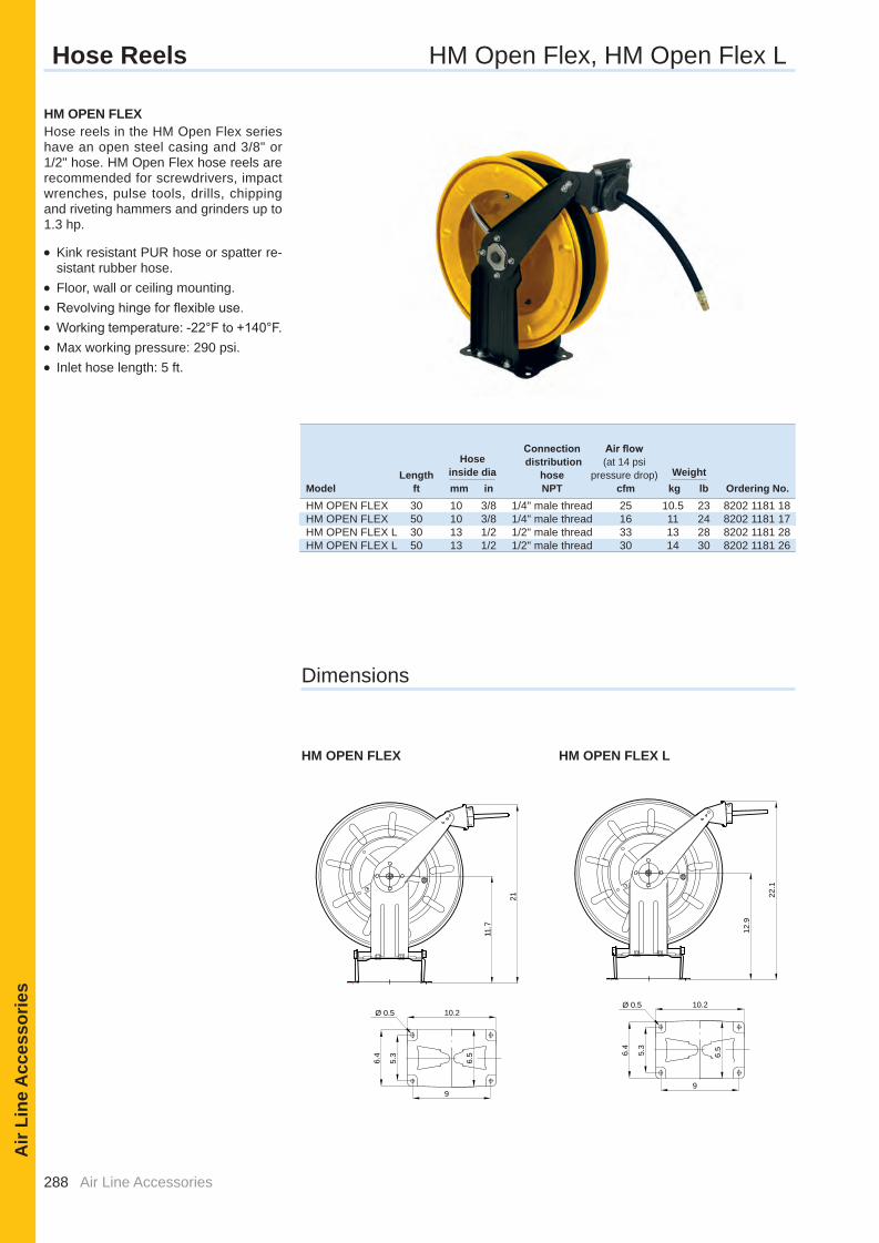
Air
Line
Acc
esso
ries
288 Air Line Accessories
11.7
21
10.2
5.3
9
6.5
6.4
Ø 0.5
12.9
22.1
10.2
5.3
9
6.56.4
Ø 0.5
HM OPEN FLEX HM OPEN FLEX L
Connection Air fl ow Hose distribution (at 14 psi Length inside dia hose pressure drop) Weight Model ft mm in NPT cfm kg lb Ordering No.HM OPEN FLEX 30 10 3/8 1/4" male thread 25 10.5 23 8202 1181 18HM OPEN FLEX 50 10 3/8 1/4" male thread 16 11 24 8202 1181 17HM OPEN FLEX L 30 13 1/2 1/2" male thread 33 13 28 8202 1181 28HM OPEN FLEX L 50 13 1/2 1/2" male thread 30 14 30 8202 1181 26
Hose Reels HM Open Flex, HM Open Flex L
HM OPEN FLEX Hose reels in the HM Open Flex series have an open steel casing and 3/8" or 1/2" hose. HM Open Flex hose reels are recommended for screwdrivers, impact wrenches, pulse tools, drills, chipping and riveting hammers and grinders up to 1.3 hp.
l Kink resistant PUR hose or spatter re-sistant rubber hose.
l Floor, wall or ceiling mounting.l Revolving hinge for fl exible use.l Working temperature: -22°F to +140°F.l Max working pressure: 290 psi.l Inlet hose length: 5 ft.
Dimensions
Am_AirLineAccessories.indd 288 2012-02-08 14:58:24
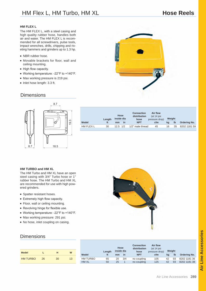
Air
Line
Acc
esso
ries
Air Line Accessories 289
8.7
18.58.7
19.3
Connection Air fl ow Hose distribution (at 14 psi Length inside dia hose pressure drop) Weight Model ft mm in NPT cfm kg lb Ordering No.HM TURBO 65 20 3/4 no coupling 105 42 93 8202 1181 36HM XL 50 25 1 no coupling 125 42 93 8202 1181 38
Connection Air fl ow Hose distribution (at 14 psi Length inside dia hose pressure drop) Weight Model ft mm in NPT cfm kg lb Ordering No.HM FLEX L 30 12.5 1/2 1/2" male thread 45 16 35 8202 1181 59
HM FLEX LThe HM FLEX L, with a steel casing and high quality rubber hose, handles both air and water. The HM FLEX L is recom-mended for all screwdrivers, pulse tools, impact wrenches, drills, chipping and riv-eting hammers and grinders up to 1.3 hp.
l NBR rubber hose.l Movable brackets for floor, wall and
ceiling mounting.l High fl ow capacity.l Working temperature: -22°F to +140°F.l Max working pressure is 219 psi.l Inlet hose length: 3.3 ft.
HM Flex L, HM Turbo, HM XL Hose Reels
Dimensions
HM TURBO and HM XLThe HM Turbo and HM XL have an open steel casing with 3/4" Turbo hose or 1" rubber hose. The HM Turbo and HM XL are recommended for use with high pow-ered grinders.
l Spatter resistant hoses. l Extremely high fl ow capacity. l Floor, wall or ceiling mounting. l Revolving hinge for fl exible use. l Working temperature: -22°F to +140°F.l Max working pressure: 291 psi.l No hose, inlet coupling on casing.
Model L H W
HM TURBO 26 30 13
Dimensions
Am_AirLineAccessories.indd 289 2012-02-08 14:59:08

Air
Line
Acc
esso
ries
290 Air Line Accessories
A
C
B
Max Max Dimensions rec. Hose working Capacity range air fl owa travel Weight pressure A B C Model kg lb cfm ft kg lb psi in in in Ordering No.HRIL 3 0.5-1.4 1.1-3.1 11.7 3.3 1.2 2.6 147 3.6 5.2 6.8 8202 0601 10HRIL 4 0.7-2.0 1.5-4.4 13.8 3.3 1.4 3.1 147 3.6 5.2 6.8 8202 0601 28
a At inlet pressure of 86 psi pressure drop is 5.7 psi.
Hose reel balancer – HRILModels in the HRIL range of hose reel balancers are specifically designed for use with small pneumatic hand tools.
The integrated air hose and support cable ensure the work area is kept tidy and the tool is easy to control.l Ergonomics – The retraction force over
hose travel remains almost constant which minimizes load on the operator and ensures smooth operation.
l An easily adjusted rubber stop is fi tted on the hose which allows the tool to be set at the optimum position.
l The retraction force is easily adjust-able by means of a hand wheel on the rear casing (this can be removed if de-sired, once the retraction force is set).
l Long service life – The design features a rugged casing, self lubricating spin-dle bearing bushes and a 360 degrees rotary inlet connector.
l A durable hose is fi tted with additional protection to prevent excessive bend-ing around air connectors.
l Low pressure drop – The HRIL balanc-ers have very good fl ow characteristics.
Hose Reels HRIL
Dimensions
Optional Accessories
Air line fi ttingsAll models have a NPT 1/4" inlet fi tting.HRIL 3 supplied with NPT 1/8" and NPT 1/4" outlet fi ttings.HRIL 4 supplied with NPT 1/4" outlet fi tting.
Designation Ordering No.
Safety chain 4391 4045 90
Am_AirLineAccessories.indd 290 2012-02-08 14:59:24
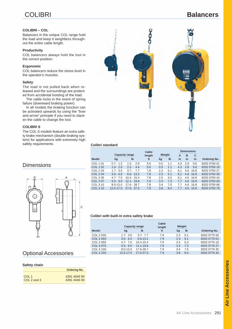
Air
Line
Acc
esso
ries
Air Line Accessories 291
B A
C
Cable Di men sions Capacity range length Weight A B CModel kg lb ft kg lb in in in Ordering No.COL 1 01 0.7- 1.3 1.5- 2.9 5.6 0.5 1.1 4.3 2.8 9.6 8202 0750 01COL 1 02 1.0- 2.0 2.2- 4.4 5.6 0.5 1.1 4.3 2.8 9.6 8202 0750 19COL 2 03 1.7- 3.5 3.7- 7.7 7.8 2.3 5.1 6.1 4.6 16.8 8202 0750 27COL 2 04 3.0- 6.0 6.6- 13.2 7.8 2.3 5.1 6.1 4.6 16.8 8202 0750 35COL 2 05 4.7- 7.0 10.4- 15.4 7.8 2.5 5.5 6.1 4.6 16.8 8202 0750 43COL 3 07 5.5- 9.0 12.1- 19.8 7.8 3.3 7.3 7.7 4.6 16.8 8202 0750 50COL 3 10 8.0-13.0 17.6- 28.7 7.8 3.4 7.5 7.7 4.6 16.8 8202 0750 68COL 3 15 12.5-17.0 27.6- 37.5 7.8 3.8 8.4 7.7 4.6 16.8 8202 0750 76
COLIBRI Balancers
Dimensions
COLIBRI – COLBalancers in the unique COL range hold the load and keep it weightless through-out the entire cable length.
ProductivityCOL balancers always hold the tool in the correct position.
ErgonomicCOL balancers reduce the stress level in the operator's muscles.
SafetyThe load is not pulled back when re-leased and the surroundings are protect-ed from accidental hoisting of the load.
The cable locks in the event of spring failure (downward braking power).
In all models the braking function can be activated upwards by using the “bow and arrow” principle if you need to slack-en the cable to change the tool.
COLIBRI SThe COL S models feature an extra safe-ty brake mechanism (double braking sys-tem) for applications with extremely high safety requirements.
Optional Accessories
Safety chain Ordering No.
COL 1 4391 4045 90COL 2 and 3 4391 4046 90
Colibri standard
Colibri with built-in extra safety brake
Cable Capacity range length WeightModel kg lb ft kg lb Ordering No.COL 2 03S 1.7- 3.5 3.7- 7.7 7.9 2.3 5.1 8202 0775 93COL 2 04S 3.0- 6.0 6.6-13.2 7.9 2.3 5.1 8202 0776 01COL 2 05S 4.7- 7.0 10.4-15.4 7.9 2.5 5.3 8202 0776 19COL 3 07S 5.5- 9.0 12.1-19.8 7.9 3.3 7.3 8202 0776 27COL 3 10S 8.0-13.0 17.6-28.7 7.9 3.4 7.5 8202 0776 35COL 3 15S 12.5-17.0 27.6-37.5 7.9 3.8 8.4 8202 0776 43
Am_AirLineAccessories.indd 291 2012-02-08 14:59:49
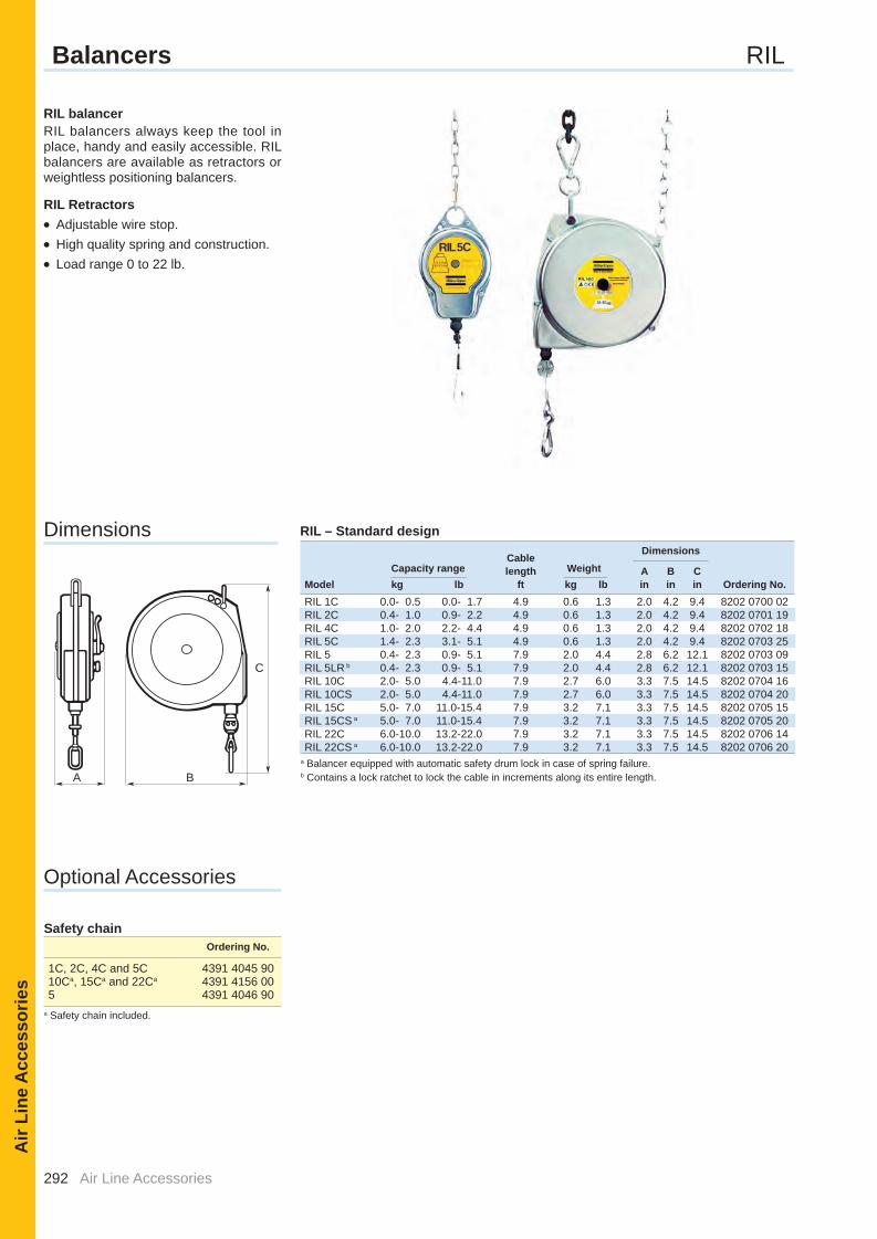
Air
Line
Acc
esso
ries
292 Air Line Accessories
A B
C
Di men sions Cable Capacity range length Weight A B CModel kg lb ft kg lb in in in Ordering No.RIL 1C 0.0- 0.5 0.0- 1.7 4.9 0.6 1.3 2.0 4.2 9.4 8202 0700 02RIL 2C 0.4- 1.0 0.9- 2.2 4.9 0.6 1.3 2.0 4.2 9.4 8202 0701 19RIL 4C 1.0- 2.0 2.2- 4.4 4.9 0.6 1.3 2.0 4.2 9.4 8202 0702 18RIL 5C 1.4- 2.3 3.1- 5.1 4.9 0.6 1.3 2.0 4.2 9.4 8202 0703 25RIL 5 0.4- 2.3 0.9- 5.1 7.9 2.0 4.4 2.8 6.2 12.1 8202 0703 09RIL 5LR b 0.4- 2.3 0.9- 5.1 7.9 2.0 4.4 2.8 6.2 12.1 8202 0703 15RIL 10C 2.0- 5.0 4.4-11.0 7.9 2.7 6.0 3.3 7.5 14.5 8202 0704 16RIL 10CS 2.0- 5.0 4.4-11.0 7.9 2.7 6.0 3.3 7.5 14.5 8202 0704 20RIL 15C 5.0- 7.0 11.0-15.4 7.9 3.2 7.1 3.3 7.5 14.5 8202 0705 15RIL 15CS a 5.0- 7.0 11.0-15.4 7.9 3.2 7.1 3.3 7.5 14.5 8202 0705 20RIL 22C 6.0-10.0 13.2-22.0 7.9 3.2 7.1 3.3 7.5 14.5 8202 0706 14RIL 22CS a 6.0-10.0 13.2-22.0 7.9 3.2 7.1 3.3 7.5 14.5 8202 0706 20
RIL balancerRIL balancers always keep the tool in place, handy and easily accessible. RIL balancers are available as retractors or weightless positioning balancers.
RIL Retractorsl Adjustable wire stop.l High quality spring and construction.l Load range 0 to 22 lb.
Balancers RIL
Dimensions
a Balancer equipped with automatic safety drum lock in case of spring failure.b Contains a lock ratchet to lock the cable in increments along its entire length.
Optional Accessories
RIL – Standard design
Safety chain Ordering No.
1C, 2C, 4C and 5C 4391 4045 9010Ca, 15Ca and 22Ca 4391 4156 005 4391 4046 90
a Safety chain included.
Am_AirLineAccessories.indd 292 2012-02-08 15:00:08
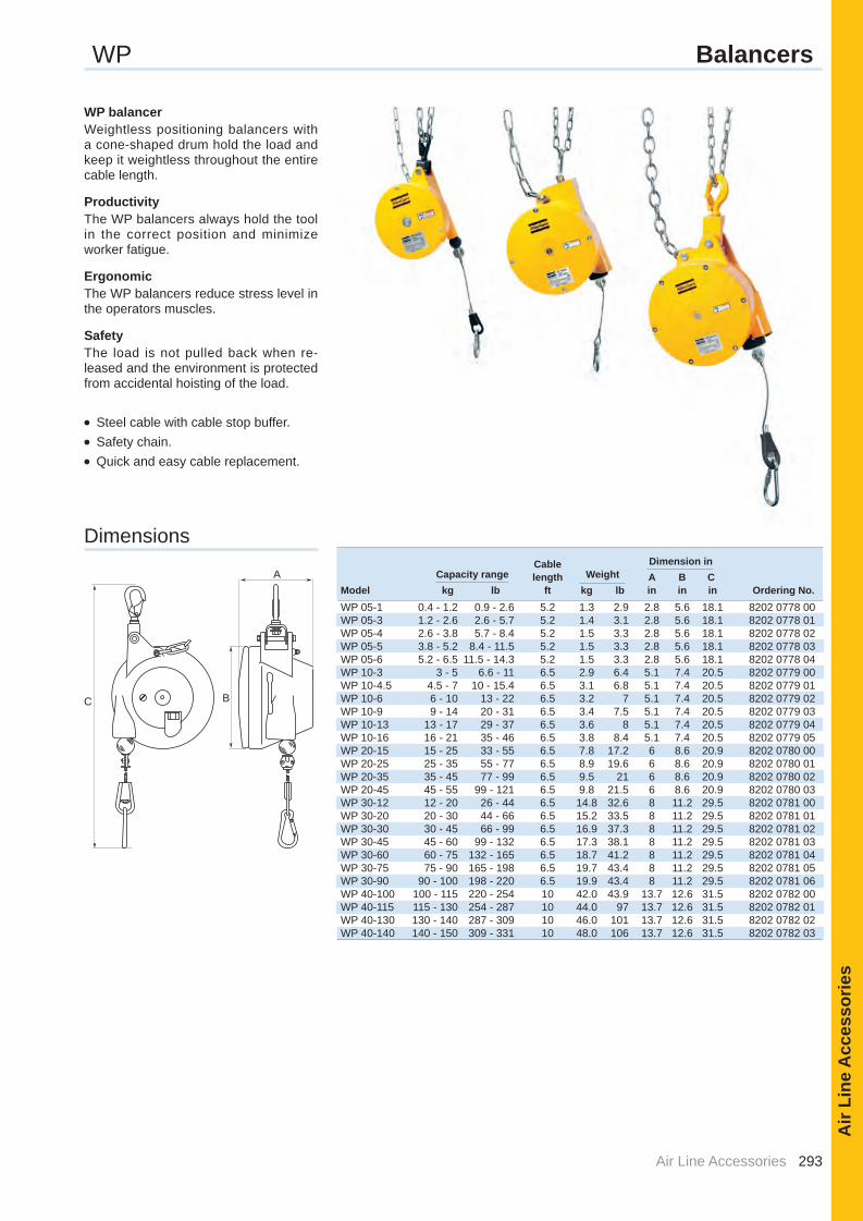
Air
Line
Acc
esso
ries
Air Line Accessories 293
Cable Di men sion in Capacity range length Weight A B CModel kg lb ft kg lb in in in Ordering No.WP 05-1 0.4 - 1.2 0.9 - 2.6 5.2 1.3 2.9 2.8 5.6 18.1 8202 0778 00WP 05-3 1.2 - 2.6 2.6 - 5.7 5.2 1.4 3.1 2.8 5.6 18.1 8202 0778 01WP 05-4 2.6 - 3.8 5.7 - 8.4 5.2 1.5 3.3 2.8 5.6 18.1 8202 0778 02WP 05-5 3.8 - 5.2 8.4 - 11.5 5.2 1.5 3.3 2.8 5.6 18.1 8202 0778 03WP 05-6 5.2 - 6.5 11.5 - 14.3 5.2 1.5 3.3 2.8 5.6 18.1 8202 0778 04WP 10-3 3 - 5 6.6 - 11 6.5 2.9 6.4 5.1 7.4 20.5 8202 0779 00WP 10-4.5 4.5 - 7 10 - 15.4 6.5 3.1 6.8 5.1 7.4 20.5 8202 0779 01WP 10-6 6 - 10 13 - 22 6.5 3.2 7 5.1 7.4 20.5 8202 0779 02WP 10-9 9 - 14 20 - 31 6.5 3.4 7.5 5.1 7.4 20.5 8202 0779 03WP 10-13 13 - 17 29 - 37 6.5 3.6 8 5.1 7.4 20.5 8202 0779 04WP 10-16 16 - 21 35 - 46 6.5 3.8 8.4 5.1 7.4 20.5 8202 0779 05WP 20-15 15 - 25 33 - 55 6.5 7.8 17.2 6 8.6 20.9 8202 0780 00WP 20-25 25 - 35 55 - 77 6.5 8.9 19.6 6 8.6 20.9 8202 0780 01WP 20-35 35 - 45 77 - 99 6.5 9.5 21 6 8.6 20.9 8202 0780 02WP 20-45 45 - 55 99 - 121 6.5 9.8 21.5 6 8.6 20.9 8202 0780 03WP 30-12 12 - 20 26 - 44 6.5 14.8 32.6 8 11.2 29.5 8202 0781 00WP 30-20 20 - 30 44 - 66 6.5 15.2 33.5 8 11.2 29.5 8202 0781 01WP 30-30 30 - 45 66 - 99 6.5 16.9 37.3 8 11.2 29.5 8202 0781 02WP 30-45 45 - 60 99 - 132 6.5 17.3 38.1 8 11.2 29.5 8202 0781 03WP 30-60 60 - 75 132 - 165 6.5 18.7 41.2 8 11.2 29.5 8202 0781 04WP 30-75 75 - 90 165 - 198 6.5 19.7 43.4 8 11.2 29.5 8202 0781 05WP 30-90 90 - 100 198 - 220 6.5 19.9 43.4 8 11.2 29.5 8202 0781 06WP 40-100 100 - 115 220 - 254 10 42.0 43.9 13.7 12.6 31.5 8202 0782 00WP 40-115 115 - 130 254 - 287 10 44.0 97 13.7 12.6 31.5 8202 0782 01WP 40-130 130 - 140 287 - 309 10 46.0 101 13.7 12.6 31.5 8202 0782 02WP 40-140 140 - 150 309 - 331 10 48.0 106 13.7 12.6 31.5 8202 0782 03
WP Balancers
Dimensions
WP balancerWeightless positioning balancers with a cone-shaped drum hold the load and keep it weightless throughout the entire cable length.
ProductivityThe WP balancers always hold the tool in the correct position and minimize worker fatigue.
ErgonomicThe WP balancers reduce stress level in the operators muscles.
SafetyThe load is not pulled back when re-leased and the environment is protected from accidental hoisting of the load.
l Steel cable with cable stop buffer.l Safety chain.l Quick and easy cable replacement.
C B
A
Am_AirLineAccessories.indd 293 2012-02-08 15:00:33
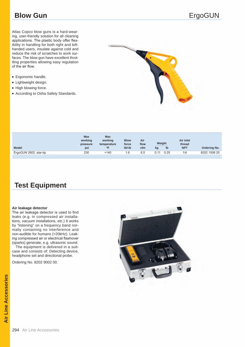
Air
Line
Acc
esso
ries
294 Air Line Accessories
Max Max working working Blow Air Air inlet pressure temperature force fl ow Weight thread Model psi ºF lbf-lb cfm kg lb NPT Ordering No.ErgoGUN 2602, star-tip 230 +140 1.6 6.5 0.11 0.25 1/4 8202 1006 20
Blow Gun ErgoGUN
Air leakage detectorThe air leakage detector is used to fi nd leaks (e.g. in compressed air installa-tions, vacuum installations, etc.) It works by ”listening” on a frequency band nor-mally containing no interference and non-audible for humans (>20kHz). Leak-ing compressed air or electrical fl ashover (sparks) generate, e.g. ultrasonic sound.
The equipment is delivered in a suit-case and consists of: Detecting device, headphone set and directional probe.
Ordering No. 8202 9002 00.
Test Equipment
Atlas Copco blow guns is a hard-wear-ing, user-friendly solution for all cleaning applications. The plastic body offer fl ex-ibility in handling for both right and left-handed users, insulate against cold and reduce the risk of scratches to work sur-faces. The blow gun have excellent throt-tling properties allowing easy regulation of the air fl ow.
l Ergonomic handle.l Lightweight design.l High blowing force.l According to Osha Safety Standards.
Am_AirLineAccessories.indd 294 2012-02-08 15:01:08

Air Motors
Contents PageVane air motors ................................. 296LZB vane air motors .......................... 297LZL vane air motors ........................... 297Air motor support ............................... 298
Am_Air Motors.indd 295 2012-02-08 15:56:21
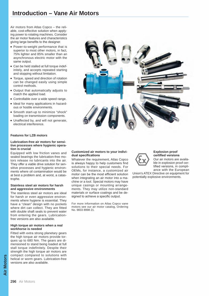
296
Air
Mot
ors
296 Air Motors
Air motors from Atlas Copco – the reli-able, cost-effective solution when apply-ing power to rotating machines. Consider the air motor features and characteristics giving large benefits to the designer.l Power-to-weight performance that is
superior to most other motors, in fact, 75% lighter and 85% smaller than an asynchronous electric motor with the same output.
l Can be held stalled at full torque indef-initely, and accepts repeated starting and stopping without limitation.
l Torque, speed and direction of rotation can be changed easily using simple control methods.
l Output that automatically adjusts to match the applied load.
l Controllable over a wide speed range.l Ideal for many applications in hazard-
ous or hostile environments.l Smooth start-up to minimize “shock”
loading on transmission components.l Unaffected by, and will not generate,
electrical interference.
Customized air motors to your indivi-dual specificationsWhatever the requirement, Atlas Copco is always happy to help customers find solutions to their special needs. For OEMs, for instance, a customized air motor can be the most efficient solution when integrating an air motor into a ma-chine or a tool. Special motors may have unique casings or mounting arrange-ments. They may utilize non-standard materials or surface coatings and be de-signed to achieve a specific output.
For more information on Atlas Copco vane motors see our air motor catalog, Ordering No. 9833 8998 21.
Features for LZB motors
Lubrication-free air motors for sensi-tive processes where hygienic opera-tion is crucialEquipped with low friction vanes and sealed bearings the lubrication-free mo-tors release no lubricants into the air. They offer a viable drive solution for sen-sitive processes and hygienic environ-ments where oil contamination would be at best a problem and, at worst, a catas-trophe.
Stainless steel air motors for harsh and aggressive environmentsThe stainless steel air motors are ideal for harsh or even aggressive environ-ments where hygiene is essential. They have a “clean” design with no pockets where dirt can collect. They are fitted with double shaft seals to prevent water from entering the gears. Lubrication-free versions are also available.
High torque air motors when a real workhorse is neededFitted with extra strong planetary gears the high torque air motors provide tor-ques up to 680 Nm. The gears are di-mensioned to stand being loaded at full stall torque indefinitely. Despite their strength the high torque air motors are compact compared to solutions with helical or worm gears. Lubrication-free versions are also available.
Introduction – Vane Air Motors
Explosion proof certified versionsOur air motors are availa-ble in explosion proof cer-tified versions, in compli-ance with the European
Union's ATEX Directive on equipment for potentially explosive environments.
Am_Air Motors.indd 296 2012-02-08 16:05:19
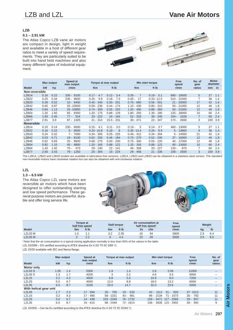
297
Air
Mot
ors
Air Motors 297
The LZB14, LZB22 and LZB33 models are available in lubrication-free versions. LZB14, LZB22 and LZB33 can be obtained in a stainless steel version. The standard non-reversible motors have clockwise rotation but can also be obtained with anti-clockwise rotation.
Speed at Free No. of Motor Max output max output Torque at max output Min start torque speed gear diameterModel kW hp r/min Nm ft lb Nm ft lb r/min ratios mm inNon-reversibleLZB14 0.16 0.22 330 - 9100 0.17 - 4.7 0.12 - 3.4 0.26 - 7 0.19 - 5.1 690 - 19500 5 27 1.1LZB22 0.25 0.34 235 - 9600 0.25 - 9.9 0.18 - 7.3 0.45 - 17 0.33 - 12.5 510 - 21500 7 36 1.4LZB33 0.39 0.52 10 - 9400 0.40 - 340 0.30 - 251 0.76 - 680 0.56 - 501 21 - 20000 17 42 1.6LZB42 0.65 0.87 25 - 10500 0.59 - 236 0.44 - 174 1.10 - 430 0.80 - 315 50 - 21000 12 46 1.8LZB46 0.84 1.13 25 - 10800 0.74 - 300 0.55 - 220 1.20 - 490 0.88 - 360 50 - 21000 12 46 1.8LZB54 1.20 1.60 65 - 9300 1.20 - 175 0.88 - 129 1.80 - 250 1.30 - 180 125 - 18000 10 60 2.4LZB66 1.83 2.45 77 - 524 33 - 222 24 - 164 52 - 333 39 - 245 154 - 1026 7 60 2.4LZB77 2.91 3.9 87 - 1325 21 - 314 15.5 - 231 30 - 471 22 - 347 174 - 2660 3 100 3.9ReversibleLZB14 0.10 0.14 230 - 6500 0.15 - 4.1 0.11 - 3.0 0.19 - 5 0.14 - 3.7 460 - 13000 5 27 1.1LZB22 0.16 0.22 5 - 6500 0.24 - 10.8 0.18 - 8 0.35 - 13.4 0.26 - 9.9 5 - 13800 9 36 1.4LZB33 0.24 0.32 7 - 7000 0.34 - 305 0.25 - 225 0.46 - 412 0.34 - 304 5 - 14000 21 42 1.6LZB42 0.53 0.71 19 - 8100 0.62 - 250 0.46 - 184 0.70 - 270 0.52 - 200 37 - 16000 12 46 1.8LZB46 0.62 0.83 20 - 8600 0.68 - 275 0.50 - 200 0.75 - 300 0.55 - 220 40 - 17000 12 46 1.8LZB54 0.82 1.10 45 - 6800 1.20 - 165 0.88 - 122 1.20 - 165 0.88 - 122 90 - 13000 10 60 2.4LZB66 1.43 1.92 70 - 473 29 - 190 22 - 141 46 - 308 33 - 227 130 - 875 7 60 2.4LZB77 2.56 3.43 79 - 1250 20 - 304 15 - 224 29 - 456 21 - 336 158 - 2500 3 100 3.9
LZL 03/05S – Can be Ex certifi ed according to the ATEX directive Ex II 2G T2 IIC D240o C.
Max output Speed at Torque at max output Min start torque Free No. of max output speed gearModel kW hp r/min Nm ft lb Nm ft lb r/min ratiosMotor onlyLZL03 S 1.05 1.4 5300 1.9 1.4 2.8 2.05 11000 –LZL05 S 1.3 1.7 4200 3 2.2 4.8 3.5 9000 –LZL15 3.2 4.3 4500 6.8 5.0 10.9 8.0 7200 –LZL25 5.0 6.7 4000 12.0 8.8 18.0 13.2 6000 –LZL35 6.5 8.7 3100 20.0 14.7 32.0 23.6 5000 –With helical gear unit LZL05 1.7 2.3 17 - 594 26 - 705 19 - 520 42 - 1112 31 - 820 37 - 1012 11LZL15 3.2 4.3 17 - 495 58 - 1331 43 - 981 96 - 2134 71 - 1573 35 - 792 11LZL25 5.0 6.7 14 - 438 103 - 2349 76 - 1732 159 - 3471 117 - 2560 29 - 657 11LZL35 6.5 8.7 19 - 615 98 - 2459 72 - 1814 156 - 3935 115 - 2902 39 - 992 9
LZL1.3 – 6.5 kWThe Atlas Copco LZL vane motors are reversible air motors which have been designed to offer outstanding starting and low speed performance. These ge-neral purpose motors are powerful, dura-ble and offer long service life.
Torque at Stall torque Air consumption at Free Weight half free speed half free speeda speedModel Nm ft lb Nm ft lb l/s cfm r/min kg lbLZL03 M 1.5 1.1 3.2 2.35 16 34 5800 2.9 6.4LZL05 M 3 2.2 6 4.4 23 49 5000 3.9 8.6
a Note that the air consumption in a typical mixing application normally is less than 50% of the values in the table.LZL 03/05M – EX certifi ed according to ATEX directive Ex II 2G T5 IIC D85o C.LZL 03/05 available with IEC and Nema fl ange.
LZB and LZL Vane Air Motors
LZB0.1 – 2.91 kWThe Atlas Copco LZB vane air motors are compact in design, light in weight and available in a host of different gear ratios to meet a variety of speed require-ments. They are particularly suited to be built into hand held machines and also many different types of industrial equip-ment.
Am_Air Motors.indd 297 2012-02-08 16:05:45
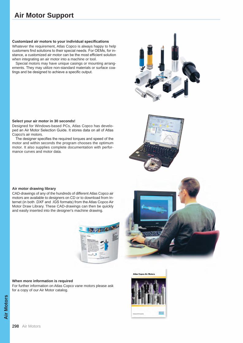
298
Air
Mot
ors
298 Air Motors
Air motor drawing libraryCAD-drawings of any of the hundreds of different Atlas Copco air motors are available to designers on CD or to download from In-ternet (in both .DXF and .IGS formats) from the Atlas Copco Air Motor Draw Library. These CAD-drawings can then be quickly and easily inserted into the designer's machine drawing.
Select your air motor in 30 seconds!Designed for Windows-based PCs, Atlas Copco has develo-ped an Air Motor Selection Guide. It stores data on all of Atlas Copco's air motors.
The designer specifi es the required torques and speed of the motor and within seconds the program chooses the optimum motor. It also supplies complete documentation with perfor-mance curves and motor data.
When more information is requiredFor further information on Atlas Copco vane motors please ask for a copy of our Air Motor catalog.
Air Motor Support
Customized air motors to your individual specifi cationsWhatever the requirement, Atlas Copco is always happy to help customers fi nd solutions to their special needs. For OEMs, for in-stance, a customized air motor can be the most effi cient solution when integrating an air motor into a machine or tool.
Special motors may have unique casings or mounting arrang-ements. They may utilize non-standard materials or surface coa-tings and be designed to achieve a specifi c output.
Am_Air Motors.indd 298 2012-02-08 16:12:36
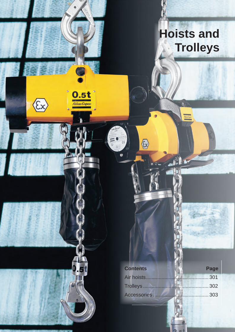
Hoists andTrolleys
Contents PageAir hoists ............................................ 301
Trolleys .............................................. 302
Accessories ....................................... 303
Am_HoistandTrolleys.indd 299 2012-02-08 16:46:39

Hoi
st a
nd T
rolle
ys
300 Hoist and Trolleys
Introduction – Air Hoists and Trolleys
Air hoist selection programThe fastest way to choose correct hoists and accessories is by using the Windows based computer program available on our website.
EXAMPLE: To order a 500 kg hoist with motor driven trolley, four button five-metrelongpendantcontrolandaloadchainfor aten-metrelift,sendthefollowing:
Order to be sent Comments
1 x 8451 1540 28 LLA500 EX Hoist block 11 x 4310 2293 00 Load chain for hoist = Required height of lift + 0.5 m, (see technical data for LLA Hoists) 1 x 8451 1520 14 TLT1000MN Motor driven trolley 1 x 4310 2263 90 4 button handle + hoist actuator 5 x 4310 2310 94 Hose set for 4 button pendant control 1 x 8990 0001 00 Instruction to assemble above items
To order your hoist or trolley with acces-soriesfactoryfitted,simplylistallitemsrequired and add the Ordering No. 8990 0001 00
Selection guide
Explosion-proof operation and stepless control for a smoothersafer lift
Atlas Copco air hoists and trolleys are the industry benchmark for fast, precise and reliable lifting of heavy loads − even in cramped and sometimes hos-tile industrial environments.
Compact and lightweight, they are easy to control, survive rough handling and provide heavyweight performance.
Explosion proof for safe operationOur air hoists and trolleys are ideal for lift applications in hazardous environme-nts.AllarecertifiedExplosion-proof,tostringent European standards, in comp-liancewiththeEUATEXDirective.Avail-able in six sizes, they offer lift capacities from 250 kg to 5 tons. All hoists and trol-leysarecertifiedtolevelExII2GT5IIB D100°C.
Simple installationThe trolleys are easy to install. The wheels are designed so that the trolley is equally suitable on both parallel and tape red I-beamsectionbeams.Thedistancebetween the wheels is easily adjusted to suit the beam width by turning the sus-pension yoke.
Am_HoistandTrolleys.indd 300 2012-02-08 16:49:48
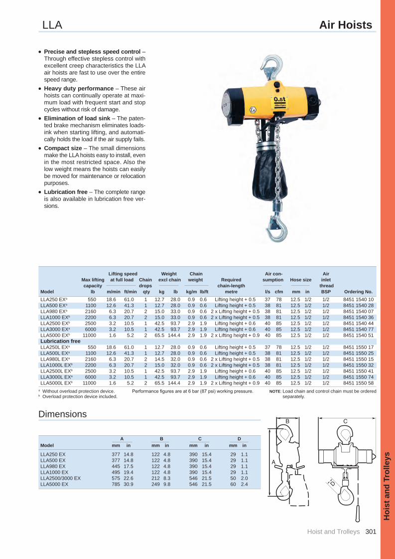
Hoi
st a
nd T
rolle
ys
Hoist and Trolleys 301
LLA Air Hoists
Lifting speed Weight Chain Air con- Air Max lifting at full load Chain excl chain weight Required sumption Hose size inlet capacity drops chain-length thread Model lb m/min ft/min qty kg lb kg/m lb/ft metre l/s cfm mm in BSP Ordering No.LLA250 EXa 550 18.6 61.0 1 12.7 28.0 0.9 0.6 Lifting height + 0.5 37 78 12.5 1/2 1/2 8451 1540 10LLA500 EXa 1100 12.6 41.3 1 12.7 28.0 0.9 0.6 Lifting height + 0.5 38 81 12.5 1/2 1/2 8451 1540 28LLA980 EXa 2160 6.3 20.7 2 15.0 33.0 0.9 0.6 2 x Lifting height + 0.5 38 81 12.5 1/2 1/2 8451 1540 07LLA1000 EXb 2200 6.3 20.7 2 15.0 33.0 0.9 0.6 2 x Lifting height + 0.5 38 81 12.5 1/2 1/2 8451 1540 36LLA2500 EXb 2500 3.2 10.5 1 42.5 93.7 2.9 1.9 Lifting height + 0.6 40 85 12.5 1/2 1/2 8451 1540 44LLA3000 EXa 6000 3.2 10.5 1 42.5 93.7 2.9 1.9 Lifting height + 0.6 40 85 12.5 1/2 1/2 8451 1540 77LLA5000 EXb 11000 1.6 5.2 2 65.5 144.4 2.9 1.9 2 x Lifting height + 0.9 40 85 12.5 1/2 1/2 8451 1540 51Lubrication free LLA250L EXa 550 18.6 61.0 1 12.7 28.0 0.9 0.6 Lifting height + 0.5 37 78 12.5 1/2 1/2 8451 1550 17LLA500L EXa 1100 12.6 41.3 1 12.7 28.0 0.9 0.6 Lifting height + 0.5 38 81 12.5 1/2 1/2 8451 1550 25LLA980L EXa 2160 6.3 20.7 2 14.5 32.0 0.9 0.6 2 x Lifting height + 0.5 38 81 12.5 1/2 1/2 8451 1550 15LLA1000L EXb 2200 6.3 20.7 2 15.0 32.0 0.9 0.6 2 x Lifting height + 0.5 38 81 12.5 1/2 1/2 8451 1550 32LLA2500L EXb 2500 3.2 10.5 1 42.5 93.7 2.9 1.9 Lifting height + 0.6 40 85 12.5 1/2 1/2 8451 1550 41LLA3000L EXa 6000 3.2 10.5 1 42.5 93.7 2.9 1.9 Lifting height + 0.6 40 85 12.5 1/2 1/2 8451 1550 74LLA5000L EXb 11000 1.6 5.2 2 65.5 144.4 2.9 1.9 2 x Lifting height + 0.9 40 85 12.5 1/2 1/2 8451 1550 58
a Without overload protection device.b Overload protection device included.
� Precise and stepless speed control – Through effective stepless control with excellent creep characteristics the LLA air hoists are fast to use over the entire speed range.
� Heavy duty performance – These air hoists can continually operate at maxi-mum load with frequent start and stop cycles without risk of damage.
� Elimination of load sink – The paten-ted brake mechanism eliminates loads-ink when starting lifting, and automati-cally holds the load if the air supply fails.
� Compact size – The small dimensions make the LLA hoists easy to install, even in the most restricted space. Also the low weight means the hoists can easily be moved for maintenance or relocation purposes.
� Lubrication free – The complete range is also available in lubrication free ver-sions.
A B C DModel mm in mm in mm in mm in
LLA250 EX 377 14.8 122 4.8 390 15.4 29 1.1LLA500 EX 377 14.8 122 4.8 390 15.4 29 1.1LLA980 EX 445 17.5 122 4.8 390 15.4 29 1.1LLA1000 EX 495 19.4 122 4.8 390 15.4 29 1.1LLA2500/3000 EX 575 22.6 212 8.3 546 21.5 50 2.0LLA5000 EX 785 30.9 249 9.8 546 21.5 60 2.4
Dimensions
Performance fi gures are at 6 bar (87 psi) working pressure. NOTE: Load chain and control chain must be ordered separately.
Am_HoistandTrolleys.indd 301 2012-02-10 11:43:59
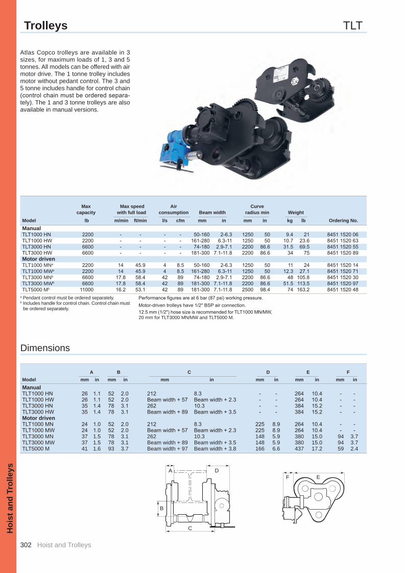
Hoi
st a
nd T
rolle
ys
302 Hoist and Trolleys
C
B
A D
EF
C
B
A D
EF
Max Max speed Air Curve capacity with full load consumption Beam width radius min Weight Model lb m/min ft/min l/s cfm mm in mm in kg lb Ordering No.Manual TLT1000HN 2200 - - - - 50-160 2-6.3 1250 50 9.4 21 8451152006TLT1000HW 2200 - - - - 161-280 6.3-11 1250 50 10.7 23.6 8451152063TLT3000HN 6600 - - - - 74-180 2.9-7.1 2200 86.6 31.5 69.5 8451152055TLT3000HW 6600 - - - - 181-300 7.1-11.8 2200 86.6 34 75 8451152089Motor driven TLT1000 MNa 2200 14 45.9 4 8.5 50-160 2-6.3 1250 50 11 24 8451152014TLT1000 MWa 2200 14 45.9 4 8.5 161-280 6.3-11 1250 50 12.3 27.1 8451152071TLT3000 MNb 6600 17.8 58.4 42 89 74-180 2.9-7.1 2200 86.6 48 105.8 8451152030TLT3000 MWb 6600 17.8 58.4 42 89 181-300 7.1-11.8 2200 86.6 51.5 113.5 8451152097TLT5000 Mb 11000 16.2 53.1 42 89 181-300 7.1-11.8 2500 98.4 74 163.2 8451152048
Performancefiguresareat6bar(87psi)workingpressure.Motor-driventrolleyshave1/2"BSPairconnection.12.5mm(1/2")hosesizeisrecommendedforTLT1000MN/MW,20 mm for TLT3000 MN/MW and TLT5000 M.
Atlas Copco trolleys are available in 3 sizes, for maximum loads of 1, 3 and 5 tonnes. All models can be offered with air motor drive. The 1 tonne trolley includes motor without pedant control. The 3 and 5 tonne includes handle for control chain (controlchainmustbeorderedsepara-tely). The 1 and 3 tonne trolleys are also available in manual versions.
a Pendant control must be ordered separately.b Includes handle for control chain. Control chain must
be ordered separately.
A B C D E FModel mm in mm in mm in mm in mm in mm inManual TLT1000HN 26 1.1 52 2.0 212 8.3 - - 264 10.4 - -TLT1000HW 26 1.1 52 2.0 Beamwidth+57 Beamwidth+2.3 - - 264 10.4 - -TLT3000HN 35 1.4 78 3.1 262 10.3 - - 384 15.2 - -TLT3000HW 35 1.4 78 3.1 Beamwidth+89 Beamwidth+3.5 - - 384 15.2 - -Motor driven TLT1000MN 24 1.0 52 2.0 212 8.3 225 8.9 264 10.4 - -TLT1000MW 24 1.0 52 2.0 Beamwidth+57 Beamwidth+2.3 225 8.9 264 10.4 - -TLT3000 MN 37 1.5 78 3.1 262 10.3 148 5.9 380 15.0 94 3.7TLT3000 MW 37 1.5 78 3.1 Beam width + 89 Beam width + 3.5 148 5.9 380 15.0 94 3.7TLT5000 M 41 1.6 93 3.7 Beam width + 97 Beam width + 3.8 166 6.6 437 17.2 59 2.4
Trolleys TLT
Dimensions
Am_HoistandTrolleys.indd 302 2012-02-08 16:50:26
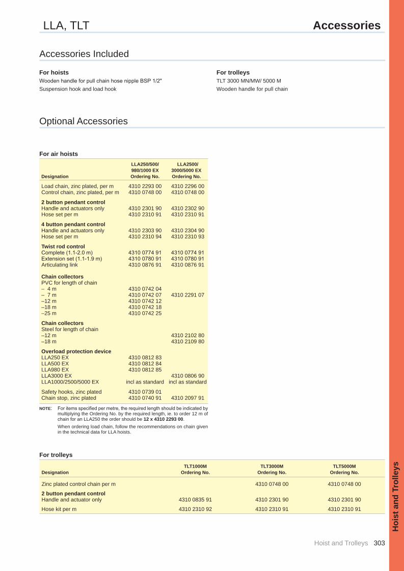
Hoi
st a
nd T
rolle
ys
Hoist and Trolleys 303
Accessories Included
Optional Accessories
For air hoists LLA250/500/ LLA2500/ 980/1000 EX 3000/5000 EXDesignation Ordering No. Ordering No.
Load chain, zinc plated, per m 4310 2293 00 4310 2296 00Control chain, zinc plated, per m 4310 0748 00 4310 0748 00
2 button pendant control Handle and actuators only 4310 2301 90 4310 2302 90Hose set per m 4310 2310 91 4310 2310 91
4 button pendant control Handle and actuators only 4310 2303 90 4310 2304 90Hose set per m 4310 2310 94 4310 2310 93
Twist rod controlComplete(1.1-2.0m) 4310077491 4310077491Extensionset(1.1-1.9m) 4310078091 4310078091Articulating link 4310 0876 91 4310 0876 91
Chain collectorsPVC for length of chain– 4 m 4310 0742 04– 7 m 4310 0742 07 4310 2291 07–12 m 4310 0742 12–18 m 4310 0742 18–25 m 4310 0742 25
Chain collectors Steel for length of chain–12 m 4310 2102 80–18 m 4310 2109 80
Overload protection device LLA250 EX 4310 0812 83 LLA500 EX 4310 0812 84 LLA980 EX 4310 0812 85LLA3000 EX 4310 0806 90LLA1000/2500/5000 EX incl as standard incl as standard
Safety hooks, zinc plated 4310 0739 01Chain stop, zinc plated 4310 0740 91 4310 2097 91
NOTE: Foritemsspecifiedpermetre,therequiredlengthshouldbeindicatedbymultiplying the Ordering No. by the required length, ie. to order 12 m of chain for an LLA250 the order should be 12 x 4310 2293 00.
When ordering load chain, follow the recommendations on chain given in the technical data for LLA hoists.
For trolleys
LLA, TLT Accessories
For hoistsWoodenhandleforpullchainhosenippleBSP1/2"Suspension hook and load hook
TLT1000M TLT3000M TLT5000MDesignation Ordering No. Ordering No. Ordering No.
Zinc plated control chain per m 4310 0748 00 4310 0748 00
2 button pendant control Handle and actuator only 4310 0835 91 4310 2301 90 4310 2301 90
Hose kit per m 4310 2310 92 4310 2310 91 4310 2310 91
For trolleysTLT 3000 MN/MW/ 5000 MWooden handle for pull chain
Am_HoistandTrolleys.indd 303 2012-02-08 16:50:26

Service
Contents PageIntroduction .......................................... 305Service packages ................................ 306Service packages for new equipment.. 308
Am_Service.indd 304 2012-02-08 17:03:55

Serv
ice
Service 305
Introduction – Atlas Copco Service
It pays to let the original manufacturer service your tools
An Atlas Copco ToolScan or a ToolScan RCM on your tool population will give you the answers to these questions. By acting on the recommendations provid-ed, many customers have reported sav-ings in production costs of up to 60%.
A properly serviced tool will perform correctly for longer periods, it will also consume less energy and get the job done faster.
Use our Operating Cost Savings Cal-culator on your tools to identify potential savings.
Are you getting the most from your air tools?l Would your tools work better with a
Preventive Maintenance Program (PM)?
l Are the tools correctly adjusted for the application?
l Have you checked your air line for cor-rect flow, air quality, leakages, etc.?
l Is your air line system correctly dimen-sioned?
l Are there areas with significant pres-sure drops?
l Do you know the status and number of tools in your production?
l What is the power efficiency (l/kWs) of your tools?
l Do you use the optimal tool for each application?
Would you like to reduce the operat-ing costs for your electric tools?l Have you calculated the total operat-
ing cost of your tools and the impact a Preventive Maintenance Program could have?
l Are you currently performing any pre-ventive maintenance, or just repairs when tools break down?
With our ToolScan RCM process we can optimize a Preventive Maintenance Pro-gram for your type of production. This can provide cost savings of up to 60% and, in some cases, even more. Our RCM Operating Cost Savings Calculator helps you to identify your total potential savings.
An Atlas Copco service program is designed to cut your production costs. The savings you can expect depend on how your production looks today – line assembly or fixed stations, tool types used, applications, frequency of tool use, work environment and other factors.
How could your production be optimized?l Is your operation really a zero-fault
production?l Could productivity be improved on
your line?l In new production projects is the focus
on quality and efficiency?
Bolted joint issues arise in all types of assembly. While the tooling is often wrongly blamed, in most cases there are other factors affecting the bolted joint. In Production Optimization we take care of these issues, both in existing production and in new projects.
Am_Service.indd 305 2012-02-08 17:08:15
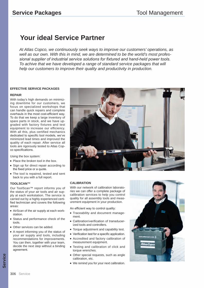
Se
rvic
e
306 Service
Service Packages Tool Management
Your ideal Service Partner
EFFECTIVE SERVICE PACKAGES
REPAIRWith today’s high demands on minimiz-ing downtime for our customers, we focus on specialized workshops that can handle quick repairs and complete overhauls in the most cost-efficient way. To do that we keep a large inventory of spare parts in stock, and we have up-graded with factory fixtures and test equipment to increase our efficiency. With all this, plus certified mechanics dedicated to specific tool models, we’ve minimized lead times and improved the quality of each repair. After service all tools are rigorously tested to Atlas Cop-co specifications.
Using the box system:l Place the broken tool in the box.l Sign up for direct repair according to
the fixed price or a quote.l The tool is repaired, tested and sent
back to you with a full report.
ToolSCAn™Our ToolScan™ report informs you of the status of your air tools and air sup-ply at each workstation. The service is carried out by a highly experienced certi-fied technician and covers the following areas:l AirScan of the air supply at each work-
station.l Status and performance check of the
tools.l Other services can be added.l A report informing you of the status of
your air supply and tools, including recommendations for improvements. You can then, together with your team, decide the next step without a binding agreement.
CAlIbRATIonWith our network of calibration laborato-ries we can offer a complete package of calibration services to help you control quality for all assembly tools and meas-urement equipment in your production.
An efficient way to control quality:l Traceability and document manage-
ment.l Calibration/verification of transducer-
ized tools and controllers.l Torque adjustment and capability test.l Verification test for a specific application.l Accredited and factory calibration of
measurement equipment.l Testing and calibration of click and
torque wrenches.l Other special requests, such as angle
calibration, etc.l We remind you for your next calibration.
At Atlas Copco, we continuously seek ways to improve our customers’ operations, as well as our own. With this in mind, we are determined to be the world’s most profes-sional supplier of industrial service solutions for fixtured and hand-held power tools. To achive that we have developed a range of standard service packages that will help our customers to improve their quality and productivity in production.
Am_Service.indd 306 2012-02-08 17:10:24

Serv
ice
Service 307
100%
Spee
d, to
rque
Oil level
Recommended oil level
Optimal performance
Risk of destroyed pulse unit
100%
Perf
orm
ance
Running time
Optimal performance
Preventive Maintenance needed
Tool breakdown
100%
Perf
orm
ance
Running time
Risk for low quality joints
Quality joints
Optimized Preventive MaintenanceStandard Preventive MaintenanceRepair on breakdown
100%
Spee
d, to
rque
Oil level
Recommended oil level
Optimal performance
Risk of destroyed pulse unit
100%
Perf
orm
ance
Running time
Optimal performance
Preventive Maintenance needed
Tool breakdown
100%
Perf
orm
ance
Running time
Risk for low quality joints
Quality joints
Optimized Preventive MaintenanceStandard Preventive MaintenanceRepair on breakdown
Risk of destroyed pulse unit
Correct lubrication of all gears is crucial for highly productive industrial tools. The most common cause of oil/grease leakage is worn seals.
Oil level decrease in small steps during operation and could end up in a destroyed pulse unit. Most of our customer have to replace the tool because of that.
By keeping your assembly tool in the low risk area the chance of failures and torque scatter is minimized.
PREVEnTIVE mAInTEnAnCE Like other machines, Atlas Copco indus-trial power tools need regular mainte-nance in order to fulfi ll their full potential in terms of performance and reliability. Different agreements are available, tai-lored to your needs. We offer main-tenance both on-site or off-site, or a combination. With our Operating Cost Calculator, you can calculate the poten-tial savings a preventive maintenance program will provide for your specific operation.
Tool Management Service Packages
Full CoVERAGEA fixed budget for all tool maintenance. Our Full Coverage option keeps power tools in top operating condition and pro-vides a fi xed budget for all tool mainte-nance. Other services can be added. To develop the optimum service program for their specific manufacturing opera-tion, customers can take advantage of our unique ToolScan RCM process. For your new tools, take a look at our Tool-Cover..
Full Coverage includes:l Repair, including parts.l Calibration.l Preventive maintenance program.l On-site/off-site options.l Other services can be added.
ToolSCAn RCmRCM (Reliability Centered Maintenance) is a proven method of rationalizing and optimizing maintenance costs in manu-facturing industries. With ToolScan RCM we balance maintenance against the operational cost of a failure. Based on our extensive tool failure statistics, we analyze your total operating costs, the tool applications and the probability of tool failure. With this information we cre-ate the optimum maintenance program for your specifi c production operation.
ouTSouRCInG SoluTIonSWe have extensive experience of out-sourcing solutions and currently have more than 75 on-site workshops. These are examples of the areas we cover:
Focus on your core business:l Preventive maintenance, repair and cal-
ibration of all brands and types of tools.l Installation and start-up support.l Service management system, includ-
ing developing Key Performance Indi-cators.
l Line and process support.l Back-up tool/equipment and spare
parts management.l Other customer requests.
Some typical KPI indicators used:l Turnaround time for repair.l MTTR (Mean Time To Repair).l MTBF (Mean Time Between Failures).l Number of preventive maintenance
actions vs. repair/failure development.l Root cause analysis.l Top 5 problem applications with ac-
tions.l Availability of equipment.
Am_Service.indd 307 2012-02-08 17:12:55
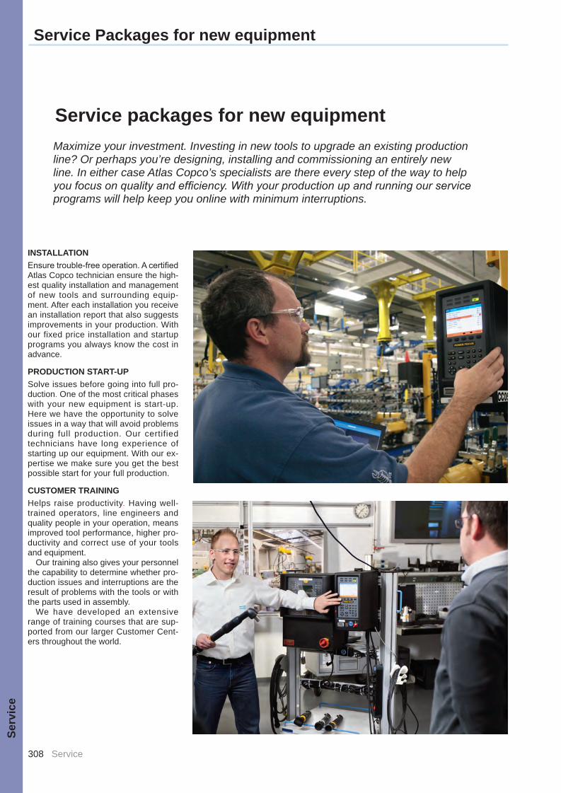
Se
rvic
e
308 Service
Service Packages for new equipment
Service packages for new equipmentMaximize your investment. Investing in new tools to upgrade an existing production line? Or perhaps you’re designing, installing and commissioning an entirely new line. In either case Atlas Copco’s specialists are there every step of the way to help you focus on quality and efficiency. With your production up and running our service programs will help keep you online with minimum interruptions.
InSTAllATIonEnsure trouble-free operation. A certified Atlas Copco technician ensure the high-est quality installation and management of new tools and surrounding equip-ment. After each installation you receive an installation report that also suggests improvements in your production. With our fixed price installation and startup programs you always know the cost in advance.
PRoduCTIon START-uPSolve issues before going into full pro-duction. One of the most critical phases with your new equipment is start-up. Here we have the opportunity to solve issues in a way that will avoid problems during full production. Our certified technicians have long experience of starting up our equipment. With our ex-pertise we make sure you get the best possible start for your full production.
CuSTomER TRAInInGHelps raise productivity. Having well-trained operators, line engineers and quality people in your operation, means improved tool performance, higher pro-ductivity and correct use of your tools and equipment.
Our training also gives your personnel the capability to determine whether pro-duction issues and interruptions are the result of problems with the tools or with the parts used in assembly.
We have developed an extensive range of training courses that are sup-ported from our larger Customer Cent-ers throughout the world.
Am_Service.indd 308 2012-02-08 17:14:53
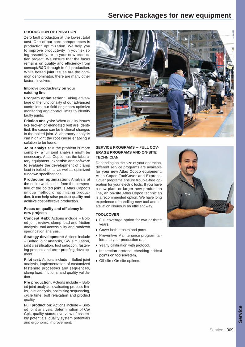
Serv
ice
Service 309
Service Packages for new equipment
PRoduCTIon oPTImIzATIonZero fault production at the lowest total cost. One of our core competences is production optimization. We help you to improve productivity in your exist-ing assembly, or in your new produc-tion project. We ensure that the focus remains on quality and efficiency from concept/R&D through to full production. While bolted joint issues are the com-mon denominator, there are many other factors involved.
Improve productivity on yourexisting lineProgram optimization: Taking advan-tage of the functionality of our advanced controllers, our field engineers optimize monitoring and control limits to identify faulty joints.Friction analysis: When quality issues like broken or elongated bolt are identi-fied, the cause can be frictional changes in the bolted joint. A laboratory analysis can highlight the root cause enabling a solution to be found.Joint analysis: If the problem is more complex, a full joint analysis might be necessary. Atlas Copco has the labora-tory equipment, expertise and software to evaluate the development of clamp load in bolted joints, as well as optimized rundown specifications.Production optimization: Analysis of the entire workstation from the perspec-tive of the bolted joint is Atlas Copco’s unique method of optimizing produc-tion. It can help raise product quality and achieve cost-effective production.
Focus on quality and efficiency in new projectsConcept R&d: Actions include – Bolt-ed joint review, clamp load and friction analysis, tool accessibility and rundown specification analysis.Strategy development: Actions include – Bolted joint analysis, SW simulation, joint classification, tool selection, fasten-ing process and error-proofing develop-ment.Pilot test: Actions include – Bolted joint analysis, implementation of customized fastening processes and sequences, clamp load, frictional and quality valida-tion.Pre production: Actions include – Bolt-ed joint analysis, evaluating process lim-its, joint analysis, optimizing sequencing, cycle time, bolt relaxation and product quality.Full production: Actions include – Bolt-ed joint analysis, determination of Cp/Cpk, quality status, overview of assem-bly potentials, quality system potentials and ergonomic improvement.
Service ProgramS ─ Full cov-ERAGE PRoGRAmS And on-SITE TECHnICIAnDepending on the size of your operation, different service programs are available for your new Atlas Copco equipment. Atlas Copco ToolCover and Express-Cover programs ensure trouble-free op-eration for your electric tools. If you have a new plant or larger new production line, an on-site Atlas Copco technician is a recommended option. We have long experience of handling new tool and in-stallation issues in an efficient way.
ToolCoVERl Full coverage option for two or three
years.l Cover both repairs and parts.l Preventive Maintenance program tai-
lored to your production rate.l Yearly calibration with protocol.l Inspection protocol checking critical
points on tools/system.l Off-site / On-site options.
Am_Service.indd 309 2012-02-08 17:21:52
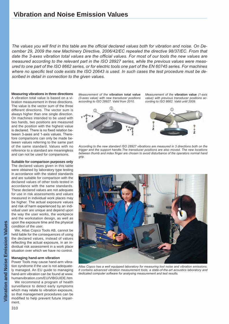
310
The values you will find in this table are the official declared values both for vibration and noise. On De-cember 29, 2009 the new Machinery Directive, 2006/42/EC repealed the directive 98/37/EC. From that date the 3-axes vibration total values are the official values. For most of our tools the new values are measured according to the relevant part in the ISO 28927 series, while the previous values were meas-ured to one part of the ISO 8662 series, or for electric tools one part of the EN 60745 series. For machines where no specific test code exists the ISO 20643 is used. In such cases the test procedure must be de-scribed in detail in connection to the given values.
Measurement of the vibration value (1-axis value) with previous transducer positions ac-cording to ISO 8662. Valid until 2009.
Measurement of the vibration total value (3-axes value) with new transducer positions according to ISO 28927. Valid from 2010.
According to the new standard ISO 28927 vibrations are measured in 3 directions both on the trigger and the support handle.The transducer positions are also moved. The new locations between thumb and index finger are chosen to avoid disturbance of the operators normal hand grip.
Measuring vibrations in three directionsA vibration total value is based on a vi-bration measurement in three directions. The value is the vector sum of the three different directions. The vector sum is always higher than one single direction. On machines intended to be used with two hands, two positions are measured and the position with the highest value is declared. There is no fixed relation be-tween 3-axes and 1-axis values. There-fore comparisons can only be made be-tween values referring to the same part of the same standard. Values with no reference to a standard are meaningless and can not be used for comparisons.
Suitable for comparison purposes only The declared values given in this table were obtained by laboratory type testing in accordance with the stated standards and are suitable for comparison with the declared values of other tools tested in accordance with the same standards. These declared values are not adequate for use in risk assessments and values measured in individual work places may be higher. The actual exposure values and risk of harm experienced by an indi-vidual user are unique and depend upon the way the user works, the workpiece and the workstation design, as well as upon the exposure time and the physical condition of the user.
We, Atlas Copco Tools AB, cannot be held liable for the consequences of using the declared values, instead of values reflecting the actual exposure, in an in-dividual risk assessment in a work place situation over which we have no control.
Managing hand-arm vibrationPower Tools may cause hand-arm vibra-tion syndrome if the use is not adequate-ly managed. An EU guide to managing hand-arm vibration can be found at www.humanvibration.com/EU/VIBGUIDE.htm
We recommend a program of health surveillance to detect early symptoms which may relate to vibration exposure, so that management procedures can be modified to help prevent future impair-ment.
Atlas Copco has a well equipped laboratory for measuring tool noise and vibration emissions. It contains advanced vibration measurement tools, a state-of-the-art acoustics laboratory and dedicated computer software for analysing measurement and test results.
Vibr
atio
n an
d N
oise
Em
issi
on V
alue
s
j j j
Vibration and Noise Emission Values
Am_TestvibrationsvalueMain.indd 310 2012-02-08 18:50:09
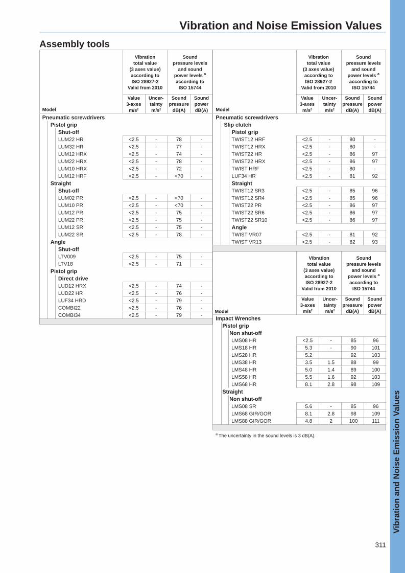
311
Vibr
atio
n an
d N
oise
Em
issi
on V
alue
s
Vibration and Noise Emission Values
Vibration total value
(3 axes value)according toISO 28927-2
Valid from 2010
Sound pressure levels
and sound power levels aaccording to
ISO 15744
Value 3-axesm/s2
Uncer-taintym/s2
Sound pressure
dB(A)
Sound powerdB(A)Model
Pneumatic screwdriversPistol grip
Shut-offLUM22 HR <2.5 - 78 -LUM32 HR <2.5 - 77 -LUM12 HRX <2.5 - 74 -LUM22 HRX <2.5 - 78 -LUM10 HRX <2.5 - 72 -LUM12 HRF <2.5 - <70 -
StraightShut-offLUM02 PR <2.5 - <70 -LUM10 PR <2.5 - <70 -LUM12 PR <2.5 - 75 -LUM22 PR <2.5 - 75 -LUM12 SR <2.5 - 75 -LUM22 SR <2.5 - 78 -
AngleShut-offLTV009 <2.5 - 75 -LTV18 <2.5 - 71 -
Pistol gripDirect driveLUD12 HRX <2.5 - 74 -LUD22 HR <2.5 - 76 -LUF34 HRD <2.5 - 79 -COMBI22 <2.5 - 76 -COMBI34 <2.5 - 79 -
Assembly toolsVibration
total value(3 axes value)according toISO 28927-2
Valid from 2010
Sound pressure levels
and sound power levels aaccording to
ISO 15744
Value 3-axesm/s2
Uncer-taintym/s2
Sound pressure
dB(A)
Sound powerdB(A)Model
Pneumatic screwdriversSlip clutch
Pistol gripTWIST12 HRF <2.5 - 80 -TWIST12 HRX <2.5 - 80 -TWIST22 HR <2.5 - 86 97TWIST22 HRX <2.5 - 86 97TWIST HRF <2.5 - 80 -LUF34 HR <2.5 - 81 92StraightTWIST12 SR3 <2.5 - 85 96TWIST12 SR4 <2.5 - 85 96TWIST22 PR <2.5 - 86 97TWIST22 SR6 <2.5 - 86 97TWIST22 SR10 <2.5 - 86 97AngleTWIST VR07 <2.5 - 81 92TWIST VR13 <2.5 - 82 93
Vibration total value
(3 axes value)according toISO 28927-2
Valid from 2010
Sound pressure levels
and sound power levels aaccording to
ISO 15744
Value 3-axesm/s2
Uncer-taintym/s2
Sound pressure
dB(A)
Sound powerdB(A)Model
Impact WrenchesPistol grip
Non shut-offLMS08 HR <2.5 - 85 96LMS18 HR 5.3 - 90 101LMS28 HR 5.2 92 103LMS38 HR 3.5 1.5 88 99LMS48 HR 5.0 1.4 89 100LMS58 HR 5.5 1.6 92 103LMS68 HR 8.1 2.8 98 109
StraightNon shut-offLMS08 SR 5.6 - 85 96LMS68 GIR/GOR 8.1 2.8 98 109LMS88 GIR/GOR 4.8 2 100 111
a The uncertainty in the sound levels is 3 dB(A).
Am_TestvibrationsvalueMain.indd 311 2012-02-08 18:50:25
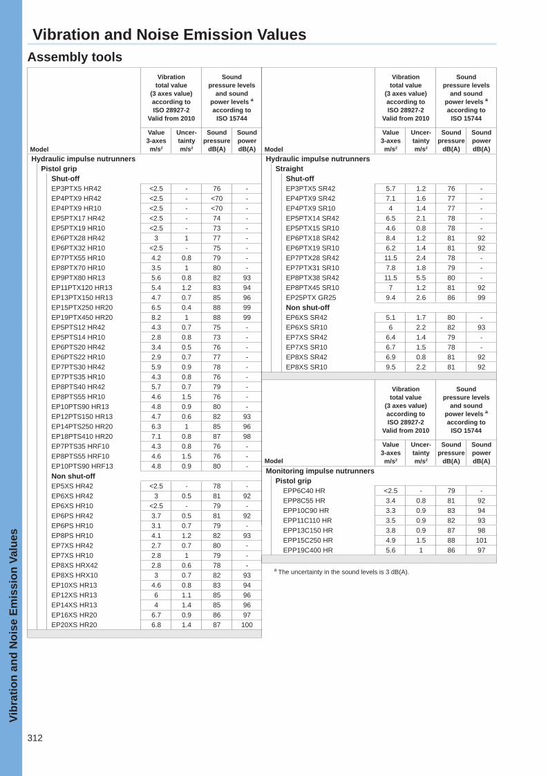
312
Vibr
atio
n an
d N
oise
Em
issi
on V
alue
s
Vibration total value
(3 axes value)according toISO 28927-2
Valid from 2010
Sound pressure levels
and sound power levels aaccording to
ISO 15744
Value 3-axesm/s2
Uncer-taintym/s2
Sound pressure
dB(A)
Sound powerdB(A)Model
Hydraulic impulse nutrunnersPistol grip
Shut-offEP3PTX5 HR42 <2.5 - 76 -EP4PTX9 HR42 <2.5 - <70 -EP4PTX9 HR10 <2.5 - <70 -EP5PTX17 HR42 <2.5 - 74 -EP5PTX19 HR10 <2.5 - 73 -EP6PTX28 HR42 3 1 77 -EP6PTX32 HR10 <2.5 - 75 -EP7PTX55 HR10 4.2 0.8 79 -EP8PTX70 HR10 3.5 1 80 -EP9PTX80 HR13 5.6 0.8 82 93EP11PTX120 HR13 5.4 1.2 83 94EP13PTX150 HR13 4.7 0.7 85 96EP15PTX250 HR20 6.5 0.4 88 99EP19PTX450 HR20 8.2 1 88 99EP5PTS12 HR42 4.3 0.7 75 -EP5PTS14 HR10 2.8 0.8 73 -EP6PTS20 HR42 3.4 0.5 76 -EP6PTS22 HR10 2.9 0.7 77 -EP7PTS30 HR42 5.9 0.9 78 -EP7PTS35 HR10 4.3 0.8 76 -EP8PTS40 HR42 5.7 0.7 79 -EP8PTS55 HR10 4.6 1.5 76 -EP10PTS90 HR13 4.8 0.9 80 -EP12PTS150 HR13 4.7 0.6 82 93EP14PTS250 HR20 6.3 1 85 96EP18PTS410 HR20 7.1 0.8 87 98EP7PTS35 HRF10 4.3 0.8 76 -EP8PTS55 HRF10 4.6 1.5 76 -EP10PTS90 HRF13 4.8 0.9 80 -Non shut-offEP5XS HR42 <2.5 - 78 -EP6XS HR42 3 0.5 81 92EP6XS HR10 <2.5 - 79 -EP6PS HR42 3.7 0.5 81 92EP6PS HR10 3.1 0.7 79 -EP8PS HR10 4.1 1.2 82 93EP7XS HR42 2.7 0.7 80 -EP7XS HR10 2.8 1 79 -EP8XS HRX42 2.8 0.6 78 -EP8XS HRX10 3 0.7 82 93EP10XS HR13 4.6 0.8 83 94EP12XS HR13 6 1.1 85 96EP14XS HR13 4 1.4 85 96EP16XS HR20 6.7 0.9 86 97EP20XS HR20 6.8 1.4 87 100
Vibration total value
(3 axes value)according toISO 28927-2
Valid from 2010
Sound pressure levels
and sound power levels aaccording to
ISO 15744
Value 3-axesm/s2
Uncer-taintym/s2
Sound pressure
dB(A)
Sound powerdB(A)Model
Hydraulic impulse nutrunnersStraight
Shut-offEP3PTX5 SR42 5.7 1.2 76 -EP4PTX9 SR42 7.1 1.6 77 -EP4PTX9 SR10 4 1.4 77 -EP5PTX14 SR42 6.5 2.1 78 -EP5PTX15 SR10 4.6 0.8 78 -EP6PTX18 SR42 8.4 1.2 81 92EP6PTX19 SR10 6.2 1.4 81 92EP7PTX28 SR42 11.5 2.4 78 -EP7PTX31 SR10 7.8 1.8 79 -EP8PTX38 SR42 11.5 5.5 80 -EP8PTX45 SR10 7 1.2 81 92EP25PTX GR25 9.4 2.6 86 99Non shut-offEP6XS SR42 5.1 1.7 80 -EP6XS SR10 6 2.2 82 93EP7XS SR42 6.4 1.4 79 -EP7XS SR10 6.7 1.5 78 -EP8XS SR42 6.9 0.8 81 92EP8XS SR10 9.5 2.2 81 92
Vibration total value
(3 axes value)according toISO 28927-2
Valid from 2010
Sound pressure levels
and sound power levels aaccording to
ISO 15744
Value 3-axesm/s2
Uncer-taintym/s2
Sound pressure
dB(A)
Sound powerdB(A)Model
Monitoring impulse nutrunnersPistol grip
EPP6C40 HR <2.5 - 79 -EPP8C55 HR 3.4 0.8 81 92EPP10C90 HR 3.3 0.9 83 94EPP11C110 HR 3.5 0.9 82 93EPP13C150 HR 3.8 0.9 87 98EPP15C250 HR 4.9 1.5 88 101EPP19C400 HR 5.6 1 86 97
a The uncertainty in the sound levels is 3 dB(A).
Vibration and Noise Emission ValuesAssembly tools
Am_TestvibrationsvalueMain.indd 312 2012-02-08 18:50:48
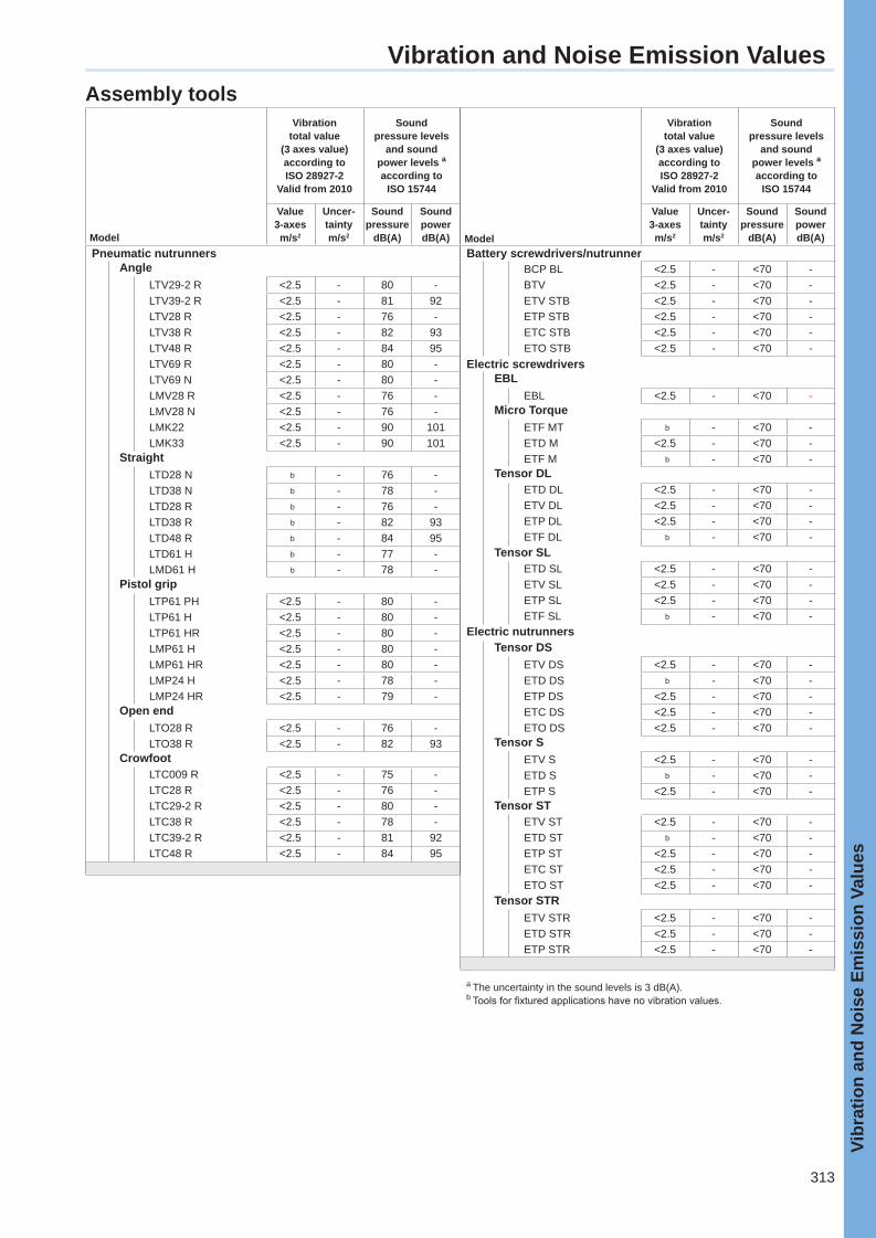
313
Vibr
atio
n an
d N
oise
Em
issi
on V
alue
s
Vibration and Noise Emission ValuesAssembly tools
Vibration total value
(3 axes value)according toISO 28927-2
Valid from 2010
Sound pressure levels
and sound power levels aaccording to
ISO 15744
Value 3-axesm/s2
Uncer-taintym/s2
Sound pressure
dB(A)
Sound powerdB(A)Model
Pneumatic nutrunnersAngle
LTV29-2 R <2.5 - 80 -LTV39-2 R <2.5 - 81 92LTV28 R <2.5 - 76 -LTV38 R <2.5 - 82 93LTV48 R <2.5 - 84 95LTV69 R <2.5 - 80 -LTV69 N <2.5 - 80 -LMV28 R <2.5 - 76 -LMV28 N <2.5 - 76 -LMK22 <2.5 - 90 101LMK33 <2.5 - 90 101
StraightLTD28 N b - 76 -LTD38 N b - 78 -LTD28 R b - 76 -LTD38 R b - 82 93LTD48 R b - 84 95LTD61 H b - 77 -LMD61 H b - 78 -
Pistol gripLTP61 PH <2.5 - 80 -LTP61 H <2.5 - 80 -LTP61 HR <2.5 - 80 -LMP61 H <2.5 - 80 -LMP61 HR <2.5 - 80 -LMP24 H <2.5 - 78 -LMP24 HR <2.5 - 79 -
Open endLTO28 R <2.5 - 76 -LTO38 R <2.5 - 82 93
Crowfoot LTC009 R <2.5 - 75 -LTC28 R <2.5 - 76 -LTC29-2 R <2.5 - 80 -LTC38 R <2.5 - 78 -LTC39-2 R <2.5 - 81 92LTC48 R <2.5 - 84 95
Vibration total value
(3 axes value)according toISO 28927-2
Valid from 2010
Sound pressure levels
and sound power levels aaccording to
ISO 15744
Value 3-axesm/s2
Uncer-taintym/s2
Sound pressure
dB(A)
Sound powerdB(A)Model
Battery screwdrivers/nutrunnerBCP BL <2.5 - <70 -BTV <2.5 - <70 -ETV STB <2.5 - <70 -ETP STB <2.5 - <70 -ETC STB <2.5 - <70 -ETO STB <2.5 - <70 -
Electric screwdriversEBL
EBL <2.5 - <70 -Micro Torque
ETF MT b - <70 -ETD M <2.5 - <70 -ETF M b - <70 -
Tensor DL ETD DL <2.5 - <70 -ETV DL <2.5 - <70 -ETP DL <2.5 - <70 -ETF DL b - <70 -
Tensor SL ETD SL <2.5 - <70 -ETV SL <2.5 - <70 -ETP SL <2.5 - <70 -ETF SL b - <70 -
Electric nutrunnersTensor DS
ETV DS <2.5 - <70 -ETD DS b - <70 -ETP DS <2.5 - <70 -ETC DS <2.5 - <70 -ETO DS <2.5 - <70 -
Tensor SETV S <2.5 - <70 -ETD S b - <70 -ETP S <2.5 - <70 -
Tensor ST ETV ST <2.5 - <70 -ETD ST b - <70 -ETP ST <2.5 - <70 -ETC ST <2.5 - <70 -ETO ST <2.5 - <70 -
Tensor STRETV STR <2.5 - <70 -ETD STR <2.5 - <70 -ETP STR <2.5 - <70 -
a The uncertainty in the sound levels is 3 dB(A).b Tools for fixtured applications have no vibration values.
Am_TestvibrationsvalueMain.indd 313 2012-02-08 18:51:10
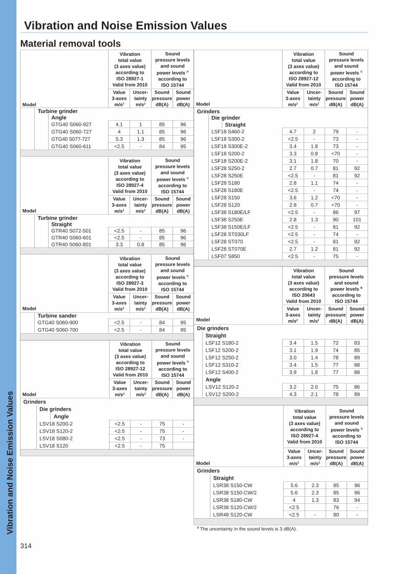
314
Vibr
atio
n an
d N
oise
Em
issi
on V
alue
s
Vibration and Noise Emission ValuesMaterial removal tools
Vibration total value
(3 axes value)according toISO 28927-1
Valid from 2010
Sound pressure levels
and sound power levels aaccording to
ISO 15744Value 3-axesm/s2
Uncer-taintym/s2
Sound pressure
dB(A)
Sound powerdB(A)Model
Turbine grinderAngleGTG40 S060-927 4.1 1 85 96GTG40 S060-727 4 1.1 85 96GTG40 S077-727 5.3 1.3 85 96GTG40 S060-611 <2.5 - 84 95
Vibration total value
(3 axes value)according toISO 28927-4
Valid from 2010
Sound pressure levels
and sound power levels aaccording to
ISO 15744Value 3-axesm/s2
Uncer-taintym/s2
Sound pressure
dB(A)
Sound powerdB(A)Model
Turbine grinderStraightGTR40 S072-501 <2.5 - 85 96GTR40 S060-601 <2.5 - 85 96GTR40 S060-801 3.3 0.8 85 96
Vibration total value
(3 axes value)according toISO 28927-3
Valid from 2010
Sound pressure levels
and sound power levels aaccording to
ISO 15744Value 3-axesm/s2
Uncer-taintym/s2
Sound pressure
dB(A)
Sound powerdB(A)Model
Turbine sanderGTG40 S060-900 <2.5 - 84 95GTG40 S060-700 <2.5 - 84 95
Vibration total value
(3 axes value)according toISO 28927-4
Valid from 2010
Sound pressure levels
and sound power levels aaccording to
ISO 15744
Value 3-axesm/s2
Uncer-taintym/s2
Sound pressure
dB(A)
Sound powerdB(A)Model
GrindersStraightLSR38 S150-CW 5.6 2.3 85 96LSR38 S150-CW/2 5.6 2.3 85 96LSR38 S180-CW 4 1.3 83 94LSR38 S120-CW/2 <2.5 76 -LSR48 S120-CW <2.5 - 80 -
a The uncertainty in the sound levels is 3 dB(A).
Vibration total value
(3 axes value)according toISO 28927-12
Valid from 2010
Sound pressure levels
and sound power levels aaccording to
ISO 15744Value 3-axesm/s2
Uncer-taintym/s2
Sound pressure
dB(A)
Sound powerdB(A)Model
GrindersDie grinders
AngleLSV18 S200-2 <2.5 - 75 -LSV18 S120-2 <2.5 - 75 -LSV18 S080-2 <2.5 - 73 -LSV18 S120 <2.5 - 75
Vibration total value
(3 axes value)according toISO 28927-12
Valid from 2010
Sound pressure levels
and sound power levels aaccording to
ISO 15744Value 3-axesm/s2
Uncer-taintym/s2
Sound pressure
dB(A)
Sound powerdB(A)Model
GrindersDie grinder
StraightLSF18 S460-2 4.7 2 79 -LSF18 S300-2 <2.5 - 73 -LSF18 S300E-2 3.4 1.8 73 -LSF18 S200-2 3.3 0.8 <70 -LSF18 S200E-2 3.1 1.8 70 -LSF28 S250-2 2.7 0.7 81 92LSF28 S250E <2.5 - 81 92LSF28 S180 2.8 1.1 74 -LSF28 S180E <2.5 - 74 -LSF28 S150 3.6 1.2 <70 -LSF28 S120 2.8 0.7 <70 -LSF38 S180E/LF <2.5 - 86 97LSF38 S250E 2.8 1.3 90 101LSF38 S150E/LF <2.5 - 81 92LSF28 ST030LF <2.5 - 74 -LSF28 ST070 <2.5 - 81 92LSF28 ST070E 2.7 1.2 81 92LSF07 S850 <2.5 - 75 -
Vibration total value
(3 axes value)according to
ISO 20643Valid from 2010
Sound pressure levels
and sound power levels aaccording to
ISO 15744Value 3-axesm/s2
Uncer-taintym/s2
Sound pressure
dB(A)
Sound powerdB(A)Model
Die grindersStraightLSF12 S180-2 3.4 1.5 72 83LSF12 S200-2 3.1 1.9 74 85LSF12 S250-2 3.0 1.4 78 89LSF12 S310-2 3.4 1.5 77 88LSF12 S400-2 3.9 1.8 77 88AngleLSV12 S120-2 3.2 2.0 75 86LSV12 S200-2 4.3 2.1 78 89
Am_TestvibrationsvalueMain.indd 314 2012-02-08 18:51:22

315
Vibr
atio
n an
d N
oise
Em
issi
on V
alue
s
Material removal tools
Vibration and Noise Emission Values
Vibration total value
(3 axes value)according toISO 28927-3
Valid from 2010
Sound pressure levels
and sound power levels aaccording to
ISO 15744
Value 3-axesm/s2
Uncer-taintym/s2
Sound pressure
dB(A)
Sound powerdB(A)Model
GrindersAngle sandersLSV28 S085 2.8 1.4 86 97LSV28 S060 <2.5 - 77 -LSV28 S040 <2.5 - 77 -LSV28 ST034 <2.5 - 86 97LSV28 S021 <2.5 - 74 -LSV38 S085 <2.5 - 85 96LSV38 S066 <2.5 - 82 93LSV38 S066 D <2.5 - 82 93LSV48 SA085 <2.5 - 87 98LSV48 SA066 <2.5 - 87 98Orbital and random orbital sandersLST30 H090-11 5.5 1.6 82 93LST30 H090-15 6.0 1.7 82 93LST30 S090-15 5.1 1.3 82 93LST31 H090-15 3.4 0.8 84 95LST32 H090-15 5.1 1.4 82 93LST32 S090-15 5.2 1.5 82 93LSO30 S070-3 11.0 1.7 81 92LSO30 H070-3 11.5 1.6 81 92LSO31 S070-3 11.0 1.7 82 93LSO31 H070-3 11.0 1.7 82 93LSO32 H070-3 7.8 1.3 79 -LST20 R350 3.8 1.7 76 -LST20 R550 4.3 1.5 76 -LST20 R650 3.4 1.3 76 -LST20 R525 4.7 2.4 76 -LST20 R625 5 2.3 76 -LST21 R350 3.8 1.7 85 96LST21 R550 3.2 1.7 85 96LST21 R650 4.4 1.5 85 96LST21 R525 3.2 1.4 85 96LST21 R625 4.6 2.9 85 96LST22 R350 3.5 1.3 78 -LST22 R550 3.9 1.4 78 -LST22 R650 5.7 2.9 78 -LST22 R525 3.2 1.4 78 -LST22 R625 3.2 1.4 78 -
Vibration total value
(3 axes value)according toISO 28927-7
Valid from 2010
Sound pressure levels
and sound power levels aaccording to
ISO 15744
Value 3-axesm/s2
Uncer-taintym/s2
Sound pressure
dB(A)
Sound powerdB(A)Model
GrindersNibblerLPN33 7.3 2.3 86 97
Vibration total value
(3 axes value)according toISO 28927-8
Valid from 2010
Sound pressure levels
and sound power levels aaccording to
ISO 15744
Value 3-axesm/s2
Uncer-taintym/s2
Sound pressure
dB(A)
Sound powerdB(A)Model
GrindersCircular cuttersLCS10 2.6 0.9 92 103LCS38 S150-D <2.5 - 86 97
a The uncertainty in the sound levels is 3 dB(A).
Vibration total value
(3 axes value)according toISO 28927-1
Valid from 2010
Sound pressure levels
and sound power levels aaccording to
ISO 15744
Value 3-axesm/s2
Uncer-taintym/s2
Sound pressure
dB(A)
Sound powerdB(A)Model
GrindersAngle grindersLSV18 S170-327/B 7.9 2.4 80 -LSV28 ST12-427 4 1.3 86 97LSV28 ST13-427E 7.3 2.5 86 97LSV38 ST12-427 3.7 1.1 77LSV38 ST12-527 4.3 1.3 77LSV48 SA066-727 4 1 89 100LSV48 SA085-727 6 1.4 93 104
Am_TestvibrationsvalueMain.indd 315 2012-02-13 08:05:58
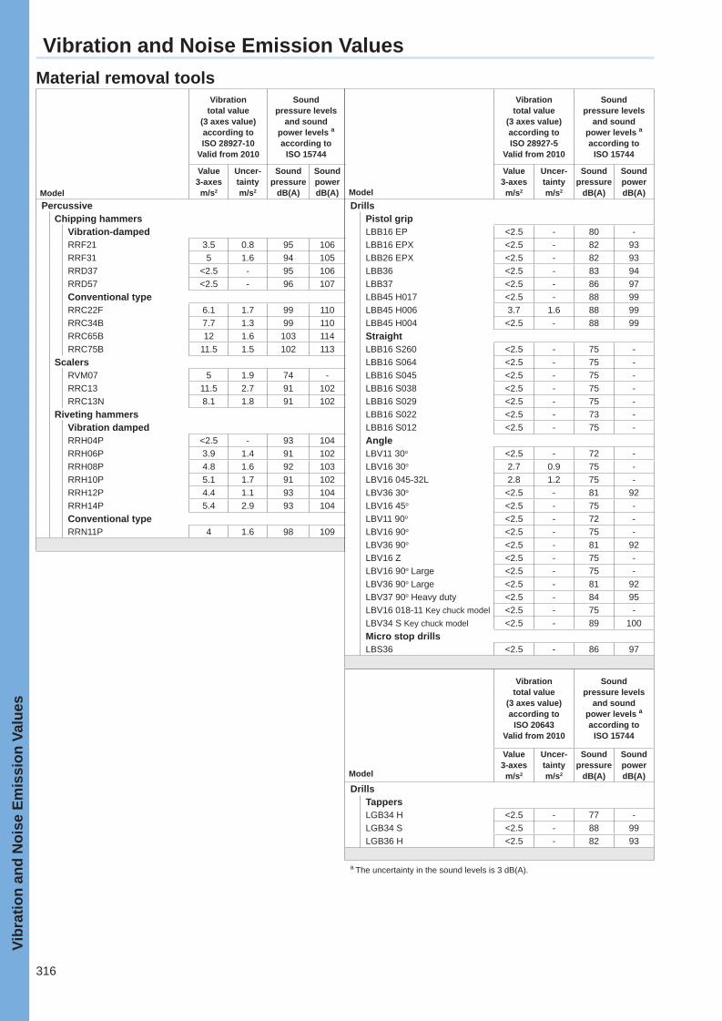
316
Vibr
atio
n an
d N
oise
Em
issi
on V
alue
s
Vibrationtotal value
(3 axes value)according toISO 28927-10
Valid from 2010
Soundpressure levels
and sound power levels aaccording to
ISO 15744
Value 3-axesm/s2
Uncer-taintym/s2
Sound pressure
dB(A)
Sound powerdB(A)Model
PercussiveChipping hammers
Vibration-dampedRRF21 3.5 0.8 95 106RRF31 5 1.6 94 105RRD37 <2.5 - 95 106RRD57 <2.5 - 96 107Conventional typeRRC22F 6.1 1.7 99 110RRC34B 7.7 1.3 99 110RRC65B 12 1.6 103 114RRC75B 11.5 1.5 102 113
ScalersRVM07 5 1.9 74 -RRC13 11.5 2.7 91 102RRC13N 8.1 1.8 91 102
Riveting hammers Vibration dampedRRH04P <2.5 - 93 104RRH06P 3.9 1.4 91 102RRH08P 4.8 1.6 92 103RRH10P 5.1 1.7 91 102RRH12P 4.4 1.1 93 104RRH14P 5.4 2.9 93 104Conventional typeRRN11P 4 1.6 98 109
Vibration and Noise Emission ValuesMaterial removal tools
Vibration total value
(3 axes value)according toISO 28927-5
Valid from 2010
Sound pressure levels
and sound power levels aaccording to
ISO 15744
Value 3-axesm/s2
Uncer-taintym/s2
Sound pressure
dB(A)
Sound powerdB(A)Model
DrillsPistol gripLBB16 EP <2.5 - 80 -LBB16 EPX <2.5 - 82 93LBB26 EPX <2.5 - 82 93LBB36 <2.5 - 83 94LBB37 <2.5 - 86 97LBB45 H017 <2.5 - 88 99LBB45 H006 3.7 1.6 88 99LBB45 H004 <2.5 - 88 99StraightLBB16 S260 <2.5 - 75 -LBB16 S064 <2.5 - 75 -LBB16 S045 <2.5 - 75 -LBB16 S038 <2.5 - 75 -LBB16 S029 <2.5 - 75 -LBB16 S022 <2.5 - 73 -LBB16 S012 <2.5 - 75 -AngleLBV11 30o <2.5 - 72 -LBV16 30o 2.7 0.9 75 -LBV16 045-32L 2.8 1.2 75 -LBV36 30o <2.5 - 81 92LBV16 45o <2.5 - 75 -LBV11 90o <2.5 - 72 -LBV16 90o <2.5 - 75 -LBV36 90o <2.5 - 81 92LBV16 Z <2.5 - 75 -LBV16 90o Large <2.5 - 75 -LBV36 90o Large <2.5 - 81 92LBV37 90o Heavy duty <2.5 - 84 95LBV16 018-11 Key chuck model <2.5 - 75 -LBV34 S Key chuck model <2.5 - 89 100Micro stop drillsLBS36 <2.5 - 86 97
Vibration total value
(3 axes value)according to
ISO 20643Valid from 2010
Sound pressure levels
and sound power levels aaccording to
ISO 15744
Value 3-axesm/s2
Uncer-taintym/s2
Sound pressure
dB(A)
Sound powerdB(A)Model
DrillsTappersLGB34 H <2.5 - 77 -LGB34 S <2.5 - 88 99LGB36 H <2.5 - 82 93
a The uncertainty in the sound levels is 3 dB(A).
Am_TestvibrationsvalueMain.indd 316 2012-02-08 18:51:38
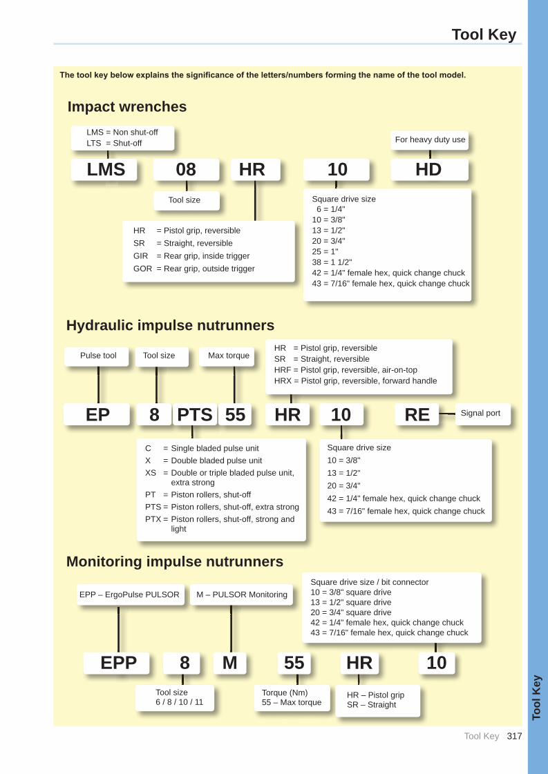
Tool
Key
Tool Key 317
Signal port
Tool Key
LMS = Non shut-offLTS = Shut-off For heavy duty use
LMS 08 HR 10 HDTool size
HR = Pistol grip, reversibleSR = Straight, reversibleGIR = Rear grip, inside triggerGOR = Rear grip, outside trigger
Square drive size 6 = 1/4"10 = 3/8"13 = 1/2"20 = 3/4"25 = 1"38 = 1 1/2"42 = 1/4" female hex, quick change chuck43 = 7/16" female hex, quick change chuck
Impact wrenches
M – PULSOR MonitoringSquare drive size / bit connector10 = 3/8" square drive13 = 1/2" square drive20 = 3/4" square drive42 = 1/4" female hex, quick change chuck43 = 7/16" female hex, quick change chuck
Tool size6 / 8 / 10 / 11
Hydraulic impulse nutrunners
The tool key below explains the signifi cance of the letters/numbers forming the name of the tool model.
HR = Pistol grip, reversibleSR = Straight, reversibleHRF = Pistol grip, reversible, air-on-topHRX = Pistol grip, reversible, forward handle
EP 8 PTS 55 HR 10 REC = Single bladed pulse unitX = Double bladed pulse unitXS = Double or triple bladed pulse unit, extra strongPT = Piston rollers, shut-offPTS = Pis ton roll ers, shut-off, ex tra strongPTX = Pis ton roll ers, shut-off, strong and light
Square drive size10 = 3/8"13 = 1/2"20 = 3/4"42 = 1/4" female hex, quick change chuck43 = 7/16" female hex, quick change chuck
EPP – ErgoPulse PULSOR
Torque (Nm)55 – Max torque
HR – Pistol gripSR – Straight
EPP 8 M 55 HR 10
Pulse tool Tool size Max torque
Monitoring impulse nutrunners
Am_ToolKeyMall.indd 317 2012-02-08 19:02:55
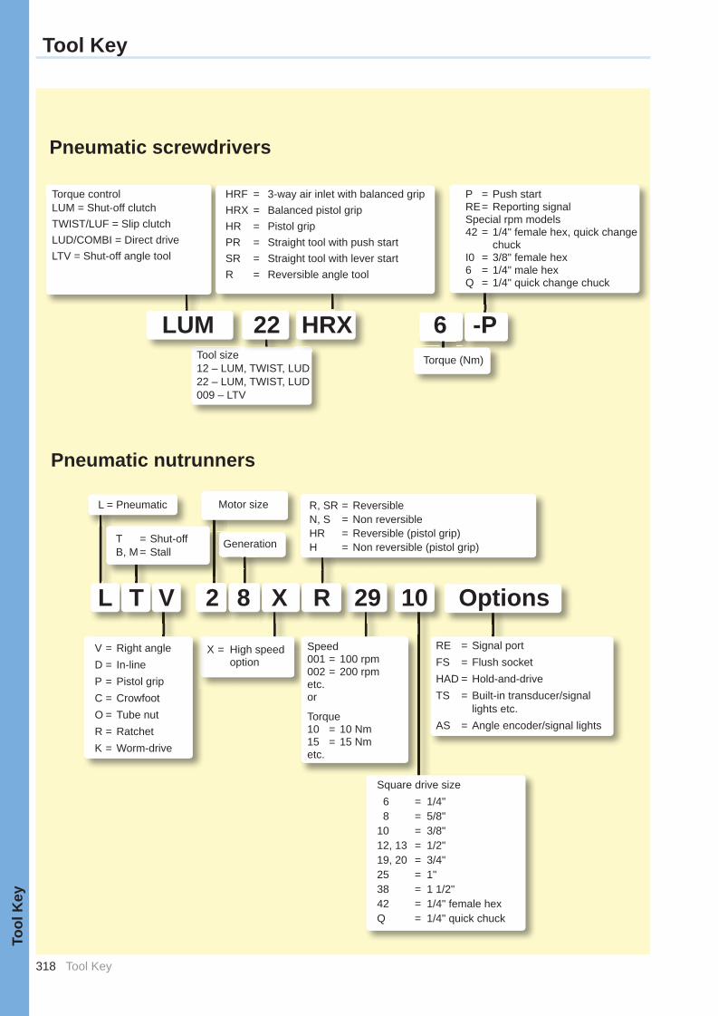
Tool
Key
318 Tool Key
Tool Key
Pneumatic nutrunners
L = Pneumatic Motor size R, SR = ReversibleN, S = Non reversibleHR = Reversible (pistol grip)H = Non reversible (pistol grip)
L T V 2 8 X R 29 10 Options
V = Right angleD = In-lineP = Pistol gripC = CrowfootO = Tube nutR = RatchetK = Worm-drive
X = High speed option
Speed001 = 100 rpm002 = 200 rpmetc.or
Torque10 = 10 Nm15 = 15 Nmetc.
Square drive size 6 = 1/4" 8 = 5/8"10 = 3/8"12, 13 = 1/2"19, 20 = 3/4"25 = 1"38 = 1 1/2"42 = 1/4" female hexQ = 1/4" quick chuck
RE = Signal portFS = Flush socketHAD = Hold-and-driveTS = Built-in transducer/signal
lights etc.AS = Angle encoder/signal lights
T = Shut-offB, M = Stall
Ge ne ra tion
Pneumatic screwdrivers
Torque controlLUM = Shut-off clutchTWIST/LUF = Slip clutchLUD/COMBI = Direct driveLTV = Shut-off angle tool
HRF = 3-way air inlet with balanced gripHRX = Balanced pistol gripHR = Pistol gripPR = Straight tool with push startSR = Straight tool with lever startR = Reversible angle tool
Torque (Nm)
LUM 22 HRX 6 -P Tool size12 – LUM, TWIST, LUD22 – LUM, TWIST, LUD009 – LTV
P = Push startRE = Reporting signalSpecial rpm models42 = 1/4" female hex, quick change chuckI0 = 3/8" female hex6 = 1/4" male hexQ = 1/4" quick change chuck
Am_ToolKeyMall.indd 318 2012-02-08 19:02:57
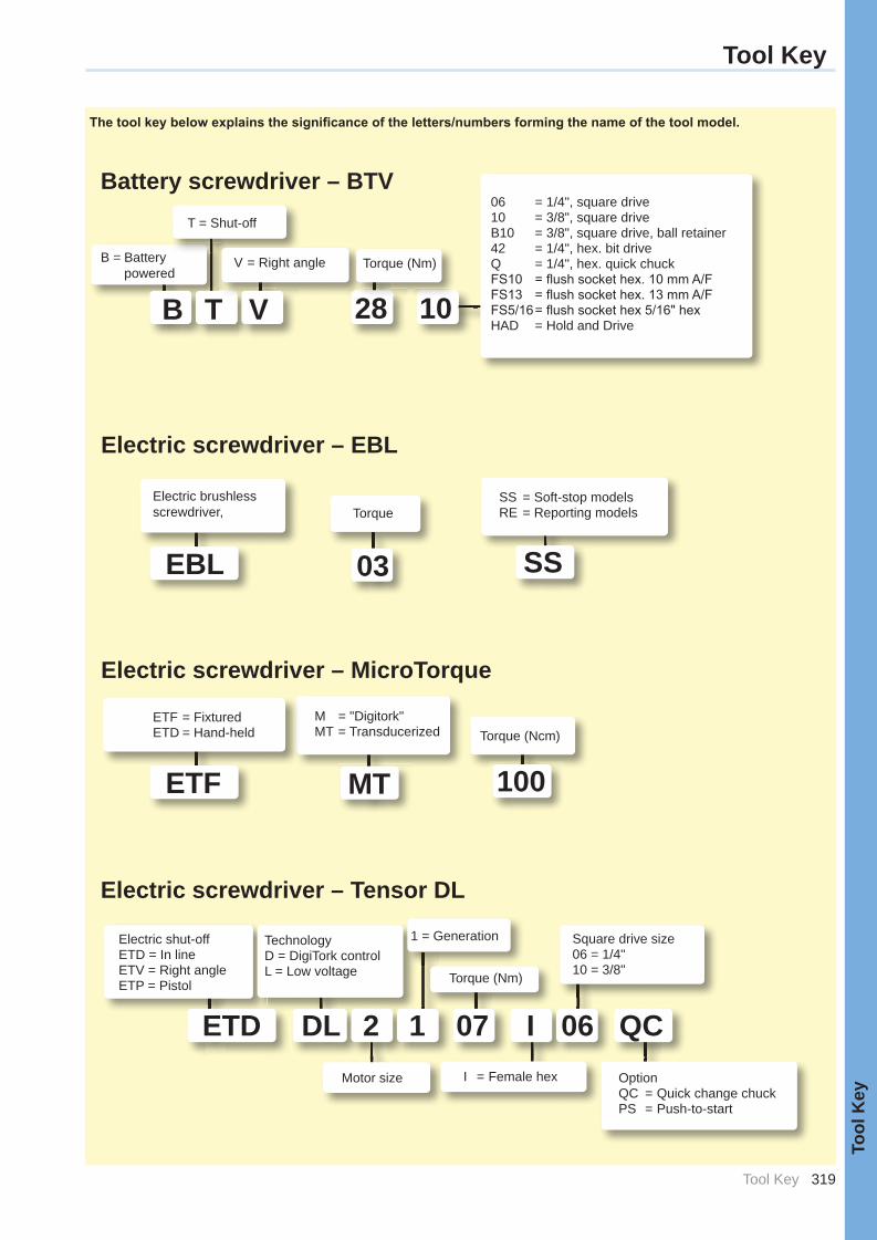
Tool
Key
Tool Key 319
Tool Key
The tool key below explains the signifi cance of the letters/numbers forming the name of the tool model.
06 = 1/4", square drive10 = 3/8", square driveB10 = 3/8", square drive, ball retainer42 = 1/4", hex. bit driveQ = 1/4", hex. quick chuckFS10 = fl ush socket hex. 10 mm A/FFS13 = fl ush socket hex. 13 mm A/FFS5/16 = fl ush socket hex 5/16" hexHAD = Hold and Drive
10B T V
B = Battery powered
T = Shut-off
V = Right angle
28Torque (Nm)
Battery screwdriver – BTV
Electric shut-offETD = In lineETV = Right angleETP = Pistol
1 = Generation
Torque (Nm)
I = Female hex
TechnologyD = DigiTork controlL = Low voltage
ETD DL 2 I 06
Electric screwdriver – Tensor DL
1 07 QCMotor size Option
QC = Quick change chuckPS = Push-to-start
Square drive size06 = 1/4"10 = 3/8"
EBL
Electric brushless screwdriver,
Electric screwdriver – EBL
Electric screwdriver – MicroTorque
03 SS
Torque (Ncm)
100
M = "Digitork"MT = Transducerized
MTETF
ETF = FixturedETD = Hand-held
TorqueSS = Soft-stop modelsRE = Reporting models
Am_ToolKeyMall.indd 319 2012-02-08 19:02:58
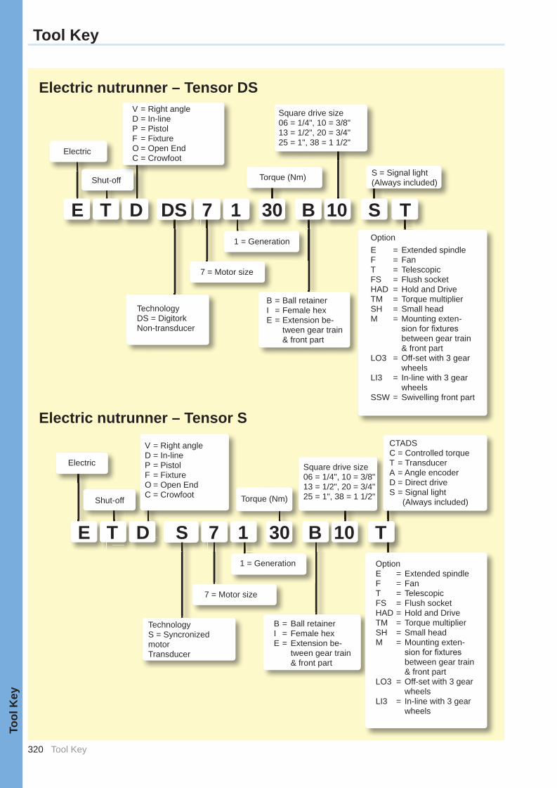
Tool
Key
320 Tool Key
Tool Key
Electric
Shut-off
1 = Generation
V = Right angleD = In-lineP = PistolF = FixtureO = Open EndC = Crowfoot
Torque (Nm)
B = Ball retainerI = Female hexE = Extension be- tween gear train & front part
TechnologyDS = DigitorkNon-transducer
E T D DS 7 B 10
Electric nutrunner – Tensor DS
1 30 T
7 = Motor size
Square drive size06 = 1/4", 10 = 3/8"13 = 1/2", 20 = 3/4"25 = 1", 38 = 1 1/2"
S = Signal light(Always included)
OptionE = Extended spindleF = FanT = TelescopicFS = Flush socketHAD = Hold and DriveTM = Torque multiplierSH = Small headM = Mounting exten- sion for fi xtures between gear train & front partLO3 = Off-set with 3 gear wheelsLI3 = In-line with 3 gear wheelsSSW = Swivelling front part
S
Electric
Shut-off
1 = Generation
V = Right angleD = In-lineP = PistolF = FixtureO = Open EndC = Crowfoot Torque (Nm)
B = Ball retainerI = Female hexE = Extension be- tween gear train & front part
TechnologyS = SyncronizedmotorTransducer
E T D S 7 B 10
Electric nutrunner – Tensor S
1 30 T
7 = Motor size
CTADSC = Controlled torqueT = TransducerA = Angle encoderD = Direct driveS = Signal light (Always included)
OptionE = Extended spindleF = FanT = TelescopicFS = Flush socketHAD = Hold and DriveTM = Torque multiplierSH = Small headM = Mounting exten- sion for fi xtures between gear train & front partLO3 = Off-set with 3 gear wheelsLI3 = In-line with 3 gear wheels
Square drive size06 = 1/4", 10 = 3/8"13 = 1/2", 20 = 3/4"25 = 1", 38 = 1 1/2"
Am_ToolKeyMall.indd 320 2012-02-08 19:03:00
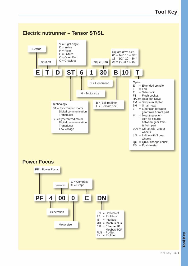
Tool
Key
Tool Key 321
Electric nutrunner – Tensor ST/SL
Torque (Nm)
TechnologyST = Syncronized motor
Digital communicationTransducer
SL = Syncronized motorDigital communicationTransducerLow voltage
B = Ball retainerI = Female hex
Electric
Shut-off
1 = Generation
V = Right angleD = In-lineP = PistolF = FixtureO = Open EndC = Crowfoot
E T D ST 6 B 101 30 T
6 = Motor size
OptionE = Extended spindleF = FanT = TelescopicFS = Flush socketHAD = Hold and DriveTM = Torque multiplierSH = Small headL = Extension between gear train & front partM = Mounting exten- sion for fi xtures between gear train & front partLO3 = Off-set with 3 gear wheelsLI3 = In-line with 3 gear wheelsQC = Quick change chuckPS = Push-to-start
Square drive size06 = 1/4", 10 = 3/8"13 = 1/2", 20 = 3/4"25 = 1", 38 = 1 1/2"
PF = Power Focus
Version
Generation
C = CompactG = Graph
DN = DeviceNetPB = Profi busIB = InterbusMB = Modbus plusEIP = Ethernet IP Modbus TCPFLN = FL-NetPN = Profi net
Motor size
PF 4 00 0 C DN
Power Focus
Tool Key
Am_ToolKeyMall.indd 321 2012-02-08 19:03:01
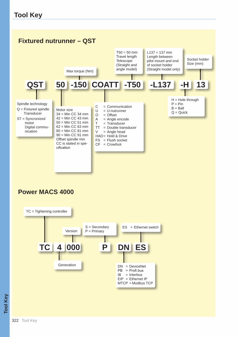
Tool
Key
322 Tool Key
TC = Tightening controller
Version
Generation
S = SecondaryP = Primary
DN = DeviceNetPB = Profi busIB = InterbusEIP = Ethernet IPMTCP = Modbus TCP
TC 4 000 P DN
Power MACS 4000
ES
ES = Ethernet switch
Fixtured nutrunner – QST
Spindle technologyQ = Fixtured spindle
TransducerST = Syncronized
motorDigital commu-nication
Max torque (Nm)
QST 50 COATT
Motor size34 = Min CC 34 mm42 = Min CC 43 mm50 = Min CC 51 mm62 = Min CC 63 mm80 = Min CC 81 mm90 = Min CC 91 mmOffset spindle min CC is stated in spe-cifi cation
C = CommunicationU = U-nutrunnerO = OffsetA = Angle encodeT = TransducerTT = Double transducerV = Angle headHAD = Hold & DriveFS = Flush socketCF = Crowfoot
-150 -T50 -H 13-L137
T50 = 50 mmTravel lengthTelescope(Straight andangle model)
L137 = 137 mmLength betweenpilot mount and endof socket holder(Straight model only)
H = Hole throughP = PinB = BallQ = Quick
Socket holderSize (mm)
Tool Key
Am_ToolKeyMall.indd 322 2012-02-08 19:03:02

323323
Tool
Des
igna
tions
Tool Designations
BAL – Ball valveBCP BL – Battery screwdriver, pistol grip, clutch typeBTV – Battery screwdriver, shut-off type, angle model
CABLAIR – CABLAIR hoseCLAW – Claw couplingCOL – Colibri balancerCOMBI – Pneumatic screwdriver, direct drive,pistol grip drill
DIM – Air preparation unit, lubricator
EBL – Electric screwdriver, brushless clutch typeEP C/X/XS – Hydraulic impulse nutrunner, non shut-off, ERGOPULSEEP PT/PTS/PTX – Hydraulic impulse nutrunner, shut-off, ERGOPULSEEPP – Monitoring impulse nutrunner, PULSOR CErgoGUN – Blow gunErgoNIP – NippleErgoQIC – Quick couplingETC DS – Electric nutrunner, shut-off type, crowfoot, TENSOR DSETC ST – Electric nutrunner, shut-off type, crowfoot, TENSOR STETC STB – Battery nutrunner, crowfoot, TENSOR STBETD DL – Electric screwdriver, shut-off type, straight model, TENSOR DLETD DS – Electric nutrunner, shut-off type, straight model, TENSOR DSETD M – Electric screwdriver, hand-held "Digitork", MicroTorqueETD S – Electric nutrunner, shut-off type, straight model, TENSOR SETD SL – Electric screwdriver, straight model, TENSOR SLETD ST – Electric nutrunner, shut-off type, straight model, TENSOR STETD STR – Electric screwdriver, straight model, TENSOR STR ETF DL – Electric screwdriver, shut-off type, fixture, TENSOR DLETF M – Electric screwdriver, fixtured "Digitork", MicroTorqueETF MT – Electric screwdriver, fixtured transducerized, MicroTorqueETF SL – Electric screwdriver, shut-off type, fixture, TENSOR SLETO DS – Electric nutrunner, shut-off type, open end, TENSOR DSETO ST – Electric nutrunner, shut-off type, open end, TENSOR STETO STB – Battery nutrunner, tube nut, TENSOR STBETP DL – Electric screwdriver, shut-off type, pistol grip, TENSOR DLETP DS – Electric nutrunner, shut-off type, pistol grip, TENSOR DSETP S – Electric nutrunner, shut-off type, pistol grip, TENSOR SETP SL – Electric screwdriver, shut-off type, pistol grip, TENSOR SLETP STB – Battery nutrunner, pistol grip TENSOR STBETP ST – Electric nutrunner, shut-off type, pistol grip, TENSOR STETP STR – Electric screwdriver, pistol grip, TENSOR STRETV DL – Electric screwdriver, shut-off type, angle model, TENSOR DLETV DS – Electric nutrunner, shut-off type, angle model, TENSOR DSETV S – Electric nutrunner, shut-off type, angle model, TENSOR SETV SL – Electric screwdriver, angle model, TENSOR SLETV ST – Electric nutrunner, shut-off type, angle model, TENSOR STETV STR – Electric screwdriver, angle model, TENSOR STRETV STB – Battery nutrunner, angle model, TENSOR STBETX – Fixtured electric nutrunner, shut-off type
FIL – Air preparation unit, filter
GHP – Torque arm, MicroTorqueGTG – Turbo grinderGTR – Straight turbo grinder
HM – Hose reelHRIL – Hose reel
IRTT-B – In-line rotary torque and torque/angle transducer
JSB – Testbenches
LBB – Pistol grip and straight drillLBL – Automatic drilling and tapping unitLBR – Pneumatic nutrunner, stall type, ratchet wrenchesLBS – Micro stop drillLBV – Angle drillLCS – Circular cuttersLGB – Tapper
LLA – Air hoist
LLT – TrolleyLMD – Pneumatic nutrunner, stall type, straight modelLMK – Pneumatic nutrunner, stall type, worm driveLMP – Pneumatic nutrunner, stall type, pistol gripLMPV – Pneumatic nutrunner, stall type, pistol grip, angle modelLMS – Impact wrenches, non shut-off typeLMV – Pneumatic nutrunner, stall type, angle modelLPN – NibblerLSF – Die grinderLSK – RoutersLSO – Orbital sanderLSR – Straight grinderLST – Random orbital sanderLSV – Angle grinder and sanderLTC – Pneumatic nutrunner, shut-off type, crowfootLTD – Pneumatic nutrunner, shut-off type, straight modelLTO – Pneumatic nutrunner, shut-off type, tube nutLTP – Pneumatic nutrunner, shut-off type, pistol gripLTPV – Pneumatic nutrunner, shut-off type, pistol grip, angle modelLTS – Impact wrenches, shut-off typeLTV – Pneumatic nutrunner/screwdriver, shut-off angle modelLUD – Pneumatic screwdriver, direct driveLUF – Pneumatic screwdriver, slip-clutch LUM – Pneumatic screwdriver, shut-off clutchLZB – Small vane air motorLZL – Vane air motor
MRTT-B – Manual screwdriver/wrench torque transducerMT TH – Torque In/Line rotary transducerMT TR – Torque&Angle In/Line rotary transducerMT TRA – Stationary torque transducerMT TS – Manual screwdriver torque transducerMultiFlex – Swivel connectors
NIP – Nipple
Optimizer – Air tool oil
PFD – Positive feed drillPOLUR – Polyurethane hosePVC – PVC hose
QIC – Quick couplingQRTT – Transducer for spindle and fixtured tool calibrationQST – Fixtured electric nutrunner, shut-off type
RAB – Screw-feed drillRAM – RammerRBB – Bucking bar, vibration dampedREG – Air preparation unit, regulatorRIL – BalancerRRC – Chipping hammer, conventional typeRRD – Chipping hammer, vibration dampedRRF – Chipping hammer, vibration dampedRRH – Riveting hammers, vibration dampedRRN – Riveting hammer, conventional typeRUBAIR – Rubber hoseRVM – Scaler, vibration damped
SM – Torque arm, parallelSMC – Telescopic reaction armSML – Torque arm, linearSMS – Torque armSPI – Spiral hoseSRTT-B – Static reaction torque transducer
TLT – TrolleyTURBO – Rubber hoseTWIST – Pneumatic screwdriver, slip-clutch
WP – Balancer
Am_Designations.indd 323 2012-02-09 07:41:19

324 324
Notes
Am_Designations.indd 324 2012-02-09 07:41:19

325325
Notes
Am_Designations.indd 325 2012-02-09 10:37:31

326 326
Notes
Am_Designations.indd 326 2012-02-09 10:37:31

327327
Notes
Am_Designations.indd 327 2012-02-09 10:37:31

328 328
Notes
Am_Designations.indd 328 2012-02-09 10:37:31

Atlas Copco ToolsNorth American Offices
The Auburn Hills facility is the new home of Atlas CopcoTools and Assembly Systems, USA. Opened in springof 2004, this site is frequently used to host trainingcourses and seminars. Customers are encouraged to visitand test run our products in our state-of-the-art demon-stration room.
A U B U R N H I L L S , M I C H I G A N
2998 Dutton Rd Phone: 800-859-ERGOAuburn Hills, MI 48326 Fax: 248-373-3001
The Canadian office was opened in 1984 and is a salesand service facility. This office has had ISO 9002approval since 1997, a quality system that is appliedto sales, service, and distribution of air powered andelectric hand held power tools.
M I S S I S S A U G A , C A N A D A
Phone: 901-501-9968Mississauga, Ontario L4Z Fax: 901-501-9790
Industrial Tools Division WarrantyAtlas Copco Tools and Assembly Systems warrants to the customer that the products manufactured byAtlas Copco Tools and Assembly Systems and its affiliates shall be free of defects in design, material,and workmanship for the following periods of time:
A. For portable industrial hand tools and hoists, twelve (12) months from date of shipment to customer.
B. All 2000 Series Tools, accessories and parts, three (3) months from date of shipment of customer.
Should any failure to conform with this warranty appear prior to or after shipment of the product tocustomer during the specified periods under normal and proper use and provided the product has beenproperly stored, installed, handled and maintained by the customer, Atlas Copco Tools and AssemblySystems shall, if given prompt notice by customer, repair or replace the nonconforming product or aut-horize repair or replacement by the distributor. Note: This does not include standard wear items such asvanes, o-rings, etc.
Replaced products become the property of Atlas Copco Tools and Assembly Systems.Atlas Copco Tools and Assembly Systems warrants Products or parts there of repaired or replaced
pursuant to the above warranty, under normal or proper use, storage, installation and maintenance,against defects in design, workmanship and material for a period of 30 days from date of start-up of suchrepaired or replaced equipment or parts or the expiration of the original product warranty, whicheveris longer.
Atlas Copco Tools and Assembly Systems´ warranty does not extend to products not manufacturedby Atlas Copco Tool and Assembly Systems or its affiliates. As to such products, customer shall beentitled to proceed only upon the terms of that particular manufacturer’s warranty does not apply todefects in material provided by customer or design stipulated by customer.
Use products, products not manufactured by Atlas Copco Tools and Assembly Systems or its affiliatesand products excluded from the above warranties are sold AS IS with no representation or warranty, andALL WARRANTIES OF QUALITY, WRITTEN, ORAL OR IMPLIED, other than may be expressly agreedto by Atlas Copco Tools and Assembly Systems. In writing, INCLUDING WITHOUT LIMITATON, WAR-RANTIES OR MERCHANTABILITY AND FITNESS ARE HEREBY DISCLAIMED.
THE FOREGOING WARRANTIES ARE EXCLUSIVE AND IN LIEU OF ALL OTHER WARRANTIESOF QUALITY, WRITTEN, ORAL OR IMPLIED AND ALL OTHER WARRANTIES INCLUDING WITHOUTLIMITATION ANY WARRANTY OF MERCHANTABILITY OR FITNESS ARE HERBY DISCLAIMED.Correction of nonconformities as provided above shall be distributor’s exclusive remedy and shall con-stitute fulfillment of all liabilities of Atlas Copco Tools and Assembly Systems (including any liability fordirect, indirect, special incidental or consequential damages) whether in warranty, strict liability, contract,tort, negligence or otherwise with respect to the quality of or any defect in products delivered here under.
OSHA StatementAtlas Copco Tools and Assembly Systems (“the company”) represents to the original user that the pro-ducts advertised herein are designed to comply with The Occupational Safety and Health Act of 1970and as amended as of the date of manufacture. The company shall not be responsible for any failure toso comply with the Act which results from the location, operation, use or maintenance of the products orfrom alteration of the products by persons other than the company or from any option or accessory of theproducts which was available to the original user but omitted at his direction, or from design or instruc-tions furnished by the original user.
The company’s responsibility herein is limited to modification or replacement of the products so thatthe products conform to the regulations applicable at the time of manufacture or at the option of the com-pany to refund to the original user the purchase price less an allowance for normal depreciation upon thereturn of the products to the company. By special request, a sound warranty can be offered; otherwiseall standards under the Act with respect to noise are specifically excluded.
Whether in relation to the above or otherwise, the company will not indemnify the original user for anyfines; penalties neither imposed nor are liable for loss due to delay or any special, indirect or consequen-tial damages of any nature whatsoever.
403 Mattheson Blvd East2H2
Har kört ut på SL-Fogra utan färgkonverte-ring!!!
AT L A S C O P C O T O O L S A N D A S S E M B LY S Y S T E M S C A N A D A
1025 Tristar Drive Phone: 289-562-0100 Mississauga, Ontario Fax: 289-562-6198 L5T 1W5
Atlas omslag insida.indd 1 2012-05-08 09.44

www.atlascopco.com
9837
30
00 21
Pri
nte
d in
Sw
eden
, Str
oki
rk-L
and
strö
ms,
2012:2.
Su
bje
ct t
o a
lter
atio
n w
ith
ou
t p
rio
r n
oti
ce.
Industrial Power Tools 2012Premier productivity solutions
Atlas C
op
co In
du
strial Pow
er Too
ls 201
2
HK catalogue10_cover 5GU.indd 1 2011-11-28 10:53:23