atherosclerosis risk in the communities study - … · aric visit 5 echocardiography field center...
TRANSCRIPT

ARIC Visit 5 Echocardiography Field Center Manual of Operations
Atherosclerosis Risk in the Communities Study
ARIC cohort – Visit 5
FINAL Echocardiography Reading Center Manual of Operations
Scott D. Solomon MD, Director
Amil M. Shah MD MPH, Associate Director
Brigham and Women’s Cardiac Imaging Core Laboratory
Boston, MA
Version: Final 11-14-2011
CONFIDENTIALITY STATEMENT: The information contained in this document, especially any unpublished material, is the property of Brigham and Women’s Hospital Echo Core Lab and is therefore provided to you in confidence as a member of the above-referenced study staff. It is understood that this information will not be disclosed to others without written authorization from Scott D. Solomon,
MD, Director of the Cardiac Imaging Core Lab.
Harvard Medical School
BRIGHAM AND WOMEN’S H O S P I T A L
Cardiac Imaging Core Lab | Brigham and Women’s Hospital
PB-A 100, 20 Shattuck Street, Boston, MA 02115, USA
Ph. 617 525 6730 | Fax. 617 582 6027

Page 2 of 22
Table of Contents
Section Page
I. Introduction 3
II. Overall Study Aims and Processes 4
III. Echocardiogram Protocol: Required Views 6
IV. Field Center Sonographer Training and Certification 7
V. CICL Data Management Processes 9
VI. Echo Reading Center Measurements 11
VII. Over-reading 18
VIII. Reporting of findings to Field Center 19
IX. CICL Echo Technician Training and Certification 21
X. Quality Assurance Plan 22

Page 3 of 22
I. Introduction
The NHLBI Atherosclerosis Risk in the Communities (ARIC) study was initiated in 1985 and follows approximately 13,000 individuals in four U.S. communities for trends in incidence and mortality of coronary heart disease. Subjects are now in their seventh to ninth decade of life, a period of life during which the prevalence of heart failure and other cardiovascular morbid conditions increases dramatically. Over 9,000 participants expected in Visit 5 will undergo an echocardiographic examination. This represents a unique opportunity to investigate perturbations in cardiac structure and function across the spectrum of HF (stages A, B, and C) and their relationship to clinical outcomes.
The Brigham and Women’s Hospital CICL will serve as the Echocardiography Reading Center for
ARIC Visit 5. This document outlines the CICL procedures for: 1. Field Center sonographer training and certification 2. Reading Center technical staff training and evaluation 3. Processing and analysis of Field Center echocardiograms 4. Reporting of abnormal measures made on echocardiograms to Field Centers for
communication to subjects’ local physicians

Page 4 of 22
II. Overall Study Aims and Processes
Ec
ho
ca
rdio
gra
ph
y
• The objective of the ARIC Visit 5 Echocardiography study is to describe and quantify perturbations in cardiac size and function across the spectrum of heart failure stages in the ARIC cohort.
• Echocardiographic examinations will be performed to estimate myocardial structure and performance including but not limited to: left and right ventricular systolic function, left ventricular end diastolic volume (LVEDV), left ventricular end systolic volume (LVESV), left ventricular mass, left atrial size, LV diastolic function, mitral inflow pulsed wave Doppler (E wave, A wave), isovolumic relaxation time (IVRT), tricuspid regurgitation (TR) velocity.
Ca
rdia
c
Ima
gin
g
Co
re L
ab
• To provide high quality reproducible quantitative analysis of study echocardiograms
OB
JE
CT
IVE
S
Sit
e
Ins
tru
cti
on
M
an
ual
• To instruct field centers on how to perform and send study echos to the Cardiac Imaging Core Lab (CICL).
Fie
ld
Ce
nte
rs
• Perform high-quality study echocardiograms per the protocol contained in this document
A
RIC
Co
ord
ina
tng
C
en
ter
• Ensure that the CICL stays informed of study-wide changes and updates as the study progresses.
• Serve as the primary liaison between the CICL and field centers for study deficiencies, chronic poor quality studies and other issues related to overall site performance.
• Provide oversight and support, as required, for the entire process
RO
LE
S A
ND
RE
SP
ON
SIB
ILIT
IES
Ca
rdia
c I
ma
gin
g
Co
re L
ab
• Receive, review and analyze study echos.
• Train and certify each field center sonographer.
• Provide field centers feedback on poor quality echos, and queries for technical/process improvement.
• Serve as a resource for sites for all echo-related questions.

Page 5 of 22
Study-Wide Process Overview
Field centers will electronically transmit echos directly to the Cardiac Imaging Core Lab (CICL). Below is a basic diagram to describe the study wide process that will occur.
STUDY-WIDE PROCESS OVERVIEW
STUDY M
EDIA
ANALYSIS
SITE TRAIN
ING
BWH
CICLSites
Sites
DCC
BWH CICLTechnical and
Non-Technical Queries
Electronic Transfer of
DataBWH CICL
1. Site Training & Training Materials*
2. Sonographer Certification Echo
3. Certification Feedback (Echo)
DCCMedia
Query Responses
Weekly Reports**
Long Term Media Storage

Page 6 of 22
III. Echocardiogram Protocol: Required Views
A. Brachial Blood pressure ♦ Ensure that BP obtained within 30 min of the echo examination
B. Parasternal Position
� Parasternal long axis
♦ 2D imaging (at deep depth)
♦ 2D imaging (at shallow depth)
♦ Color Doppler of the mitral and aortic valves
� Parasternal short axis – Aortic valve level
♦ 2D imaging of AV
♦ Color Doppler of AV
♦ 2D imaging of right ventricular outflow tract
♦ Color Doppler of right ventricular outflow tract
♦ PW and CW Doppler of the RVOT
� Parasternal short axis – Mitral valve level
♦ 2D imaging
� Parasternal short axis – Papillary muscle level
♦ 2D imaging
♦ M-mode
� Parasternal short axis – LV apex
♦ 2D imaging
C. Apical Position
� Apical 4 chamber view ♦ 2D imaging
♦ 2D imaging, focused/zoomed on LV
♦ 2D imaging, focused on LA
♦ Color Doppler of mitral valve/LA
♦ PW Doppler of mitral flow
♦ TDI of septal and lateral mitral annulus
♦ iRotate to 2-chamber view (2D imaging)
♦ iRotate to 3-chamber view (2d imaging)
♦ 3D full volume acquisition of LV
♦ 3D full volume acquisition of RV
� Apical 4 chamber – focused on the RV
♦ 2D imaging
♦ Color Doppler of tricuspid valve/RA
♦ CW Doppler of tricuspid regurgitation
♦ TDI of lateral tricuspid annulus
� Apical 5 chamber view ♦ 2D imaging
♦ Color Doppler of left ventricular outflow tract
♦ Pulse wave of LVOT flow
♦ CW of transaortic flow
� Apical 2 chamber view ♦ 2D imaging focused/zoomed on LV
♦ 2D imaging focused on LA
♦ Color Doppler MV/LA
� Apical 3 chamber view ♦ 2D imaging
D. Subcostal View
� Inferior vena cava ♦ 2D imaging (5 second acquisition)

Page 7 of 22
IV. Field Center Sonographer Training and Certification
Sonographer training Sonographer training is a multilayer process and includes the following components:
Live training session – Prior to the start of Visit 5, a centralized training session will be help for all Field Center sonographers who will be performing echocardiograms for the ARIC study. A CICL project investigator, a senior CICL sonographer, and the CICL project coordinator will be present. Training will consist of a didactic session, reviewing the exam protocol, machine presets, required views, image acquisition/optimization tips, and mechanisms for the Field Center staff to contact CICL staff regarding technical questions or issues. A hands-on session will then be led by the CICL sonographer, initially demonstrating a full study exam on a model patient using the echo machine model identical to that used for Visit 5 echos, then allowing each sonographer to perform the full exam under direct supervision. A presentation and demonstration of the process for transmitting studies to the CICL will be made. Reference materials at the Field Centers – Prior to and during the Visit 5 period, the Reading Center will provide to following reference materials for Field Center sonographers. These will also be available online via the CICL secure website. Field Center Manual of Operations containing the protocol required views and instructions for optimizing image quality. Training DVD demonstrating a full ARIC echo study performed per the study protocol with narrative and moving echo clips. Pocket Guide which is a 1 page guide (laminated and put on a key ring) listing key study data including required views to obtain and instructions for sending echocardiograms to the CICL. Monitoring and feedback – During the Visit 5 period, CICL technical staff will continuously monitor the adequacy and quality of all studies received. Feedback regarding adequacy of each study received, including an itemized list of study deficits if deemed inadequate, are sent to the Field Center following analysis. If a study is deemed to be insufficiently performed, a request via the feedback form will be made to repeat the study if possible. A pattern of inadequate or poor quality studies will prompt directed discussion by CICL staff with the Field Center and/or sonographer and, possibly, retraining.

Page 8 of 22
Sonographer Certification The purpose of certification is to ensure consistency in how echocardiograms are performed
study-wide and to ensure performance of the highest quality echocardiograms. Any sonographer who will be performing study echocardiograms must first submit two certification studies performed in accordance with the protocol described in this manual and transferred electronically to the CICL for review and certification.
Studies will be scrutinized for adherence to protocol, acquisition of all required views, and image quality. Itemized direct written feedback and suggestions from the technical project manager will be provided for each study submitted. This is intended to address any individual equipment or operator dependent problems that may arise. Sonographers will have the opportunity to re-submit a sample protocol study should the initial submission be inadequate. Following submission of an adequate sample study, the sonographer will be officially certified and will receive feedback documenting this.
New Field Center sonographers starting during the study period will be required undergo the certification process outlined above by submitting 2 sample protocol studies in order to demonstrate the ability to perform a technically adequate protocol study and the knowledge to successfully transmit this data to the CICL.
A general outline of the process is outlined below.
Page 9 of 22
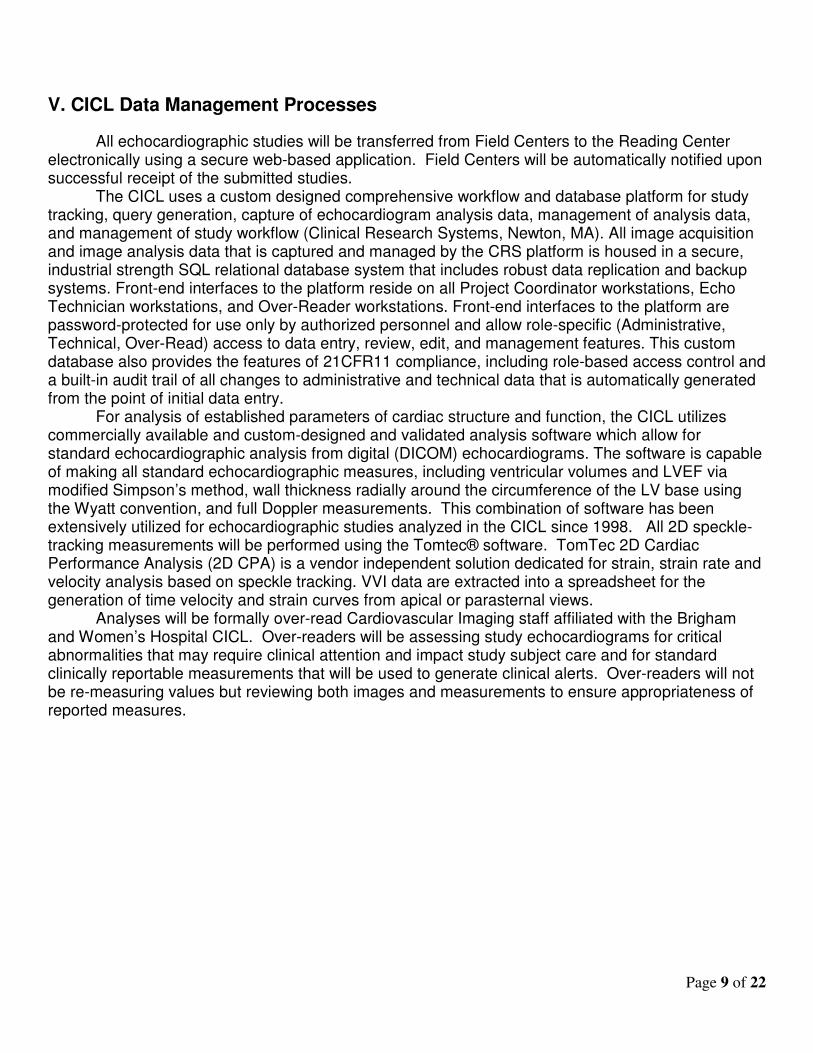
V. CICL Data Management Processes
All echocardiographic studies will be transferred from Field Centers to the Reading Center electronically using a secure web-based application. Field Centers will be automatically notified upon successful receipt of the submitted studies.
The CICL uses a custom designed comprehensive workflow and database platform for study tracking, query generation, capture of echocardiogram analysis data, management of analysis data, and management of study workflow (Clinical Research Systems, Newton, MA). All image acquisition and image analysis data that is captured and managed by the CRS platform is housed in a secure, industrial strength SQL relational database system that includes robust data replication and backup systems. Front-end interfaces to the platform reside on all Project Coordinator workstations, Echo Technician workstations, and Over-Reader workstations. Front-end interfaces to the platform are password-protected for use only by authorized personnel and allow role-specific (Administrative, Technical, Over-Read) access to data entry, review, edit, and management features. This custom database also provides the features of 21CFR11 compliance, including role-based access control and a built-in audit trail of all changes to administrative and technical data that is automatically generated from the point of initial data entry.
For analysis of established parameters of cardiac structure and function, the CICL utilizes commercially available and custom-designed and validated analysis software which allow for standard echocardiographic analysis from digital (DICOM) echocardiograms. The software is capable of making all standard echocardiographic measures, including ventricular volumes and LVEF via modified Simpson’s method, wall thickness radially around the circumference of the LV base using the Wyatt convention, and full Doppler measurements. This combination of software has been extensively utilized for echocardiographic studies analyzed in the CICL since 1998. All 2D speckle-tracking measurements will be performed using the Tomtec® software. TomTec 2D Cardiac Performance Analysis (2D CPA) is a vendor independent solution dedicated for strain, strain rate and velocity analysis based on speckle tracking. VVI data are extracted into a spreadsheet for the generation of time velocity and strain curves from apical or parasternal views.
Analyses will be formally over-read Cardiovascular Imaging staff affiliated with the Brigham and Women’s Hospital CICL. Over-readers will be assessing study echocardiograms for critical abnormalities that may require clinical attention and impact study subject care and for standard clinically reportable measurements that will be used to generate clinical alerts. Over-readers will not be re-measuring values but reviewing both images and measurements to ensure appropriateness of reported measures.

Page 10 of 22

Page 11 of 22
VI. Echo Reading Center Measurements
1. Assessment of Global Left Ventricular Size and Function
From the parasternal long or short axis view/M-Mode below the tips of the mitral valve, the end-diastolic dimensions as well as the interventricular septum thickness and posterior wall thickness of the left ventricle will be measured according to the recommendations of the American Society of Echocardiography. From the 4-chamber and 2-chamber apical views, the endocardial borders will be traced in both end-diastole and end-systole to obtain left ventricular areas. Left ventricular volumes will be obtained utilizing the Simpson’s rule algorithm and average of four chamber and two chamber single plane volumes.
Parasternal long axis view:
• End-diastolic left ventricular diameter (cm) [LVIDd]
• End-systolic left ventricular diameter (cm) [LVIDs]
• Interventricular septum thickness [ASWT]
• Posterior wall thickness [PWT]
Apical 4 Chamber View
• End diastolic volume (ml)
• End systolic volume (ml)
Apical 2 Chamber View
• End diastolic volume (ml)
• End systolic volume (ml)
Derived Measurements
• Ejection fraction (%) = 100 *(LVEDV – LVESV)/LVEDV
• LV mass (g) = = 0.8*{1.04*[(LVIDd+IVSTd+PWTd)3 −(LVIDd)3]}+0.6
• LV relative wall thickness = (2*PWT)/LVIDd
• Mean LV wall thickness (cm) = (PWT+ASWT)/2

Page 12 of 22
2. Assessment of Left Ventricular Diastolic function:
The peak velocities of the early rapid filling wave (E wave), and the peak velocity of the late filling wave (A wave) will be measured. The deceleration time of the E wave will be measured as the interval from the peak E wave to its extrapolation to the baseline. In situations where the A wave merges with the E wave, deceleration time will be measured as the extrapolation of the E wave slope to the baseline. Mitral annular velocities (for tissue Doppler imaging) will be recorded in systole and diastole at the lateral and septal annulus in 4-chamber view. Early diastolic myocardial velocity (Em) and late diastolic myocardial velocity (Am) will be measured at the lateral and septal annulus. Peak tricuspid regurgitation velocity will be measured using continuous wave Doppler through the tricuspid valve.
Apical 4 Chamber View
Mitral Inflow Doppler at the tips of the mitral leaflets
• Peak E wave velocity (cm/sec)
• Peak A wave velocity (cm/sec)
• Deceleration time (msec)
Tissue Doppler Imaging
• Lateral early diastolic myocardial velocity (Em lateral)
• Lateral late diastolic myocardial velocity (Am lateral)
• Lateral systolic myocardial velocity (Sm lateral)
• Septal early diastolic myocardial velocity (Em septal)
• Septal late diastolic myocardial velocity (Am septal)
• Septal systolic myocardial velocity (Sm septal)
Tricuspid Regurgitation Doppler (Continuous Wave)
• Peak tricuspid regurgitation velocity (m/sec)
Derived Variables:
1. E/A ratio
2. E/Em lateral ratio

Page 13 of 22
3. Assessment of Left Atrial Size
From the parasternal long axis view, the maximal left atrial diameter will be measured according to the recommendations of the American Society of Echocardiography.
From the apical 4-chamber view left atrial endocardial borders will be traced, and a straight line will be extrapolated connecting the attachment points of the mitral leaflets to the valve ring. LA volumes will be determined at mitral valve opening using the Simpson’s method of discs. Parasternal long axis view
• Maximal left atrial diameter (cm)
Apical 4 Chamber View
• 4-Chamber Left atrial volume at mitral valve opening (ml)
Apical 2 Chamber View
• 4-Chamber Left atrial volume at mitral valve opening (ml)
Derived Variable:
• LA volume index (ml/m2) = LA volume/BSA
4. Assessment of Mitral Regurgitation
From the apical 4-chamber view, the borders of the mitral regurgitation color Doppler profile at its maximal extent during systole will be traced.
Apical 4 Chamber View
• Mitral regurgitation jet area (cm2)
Derived Variable:
• MR jet area (cm2)/ Left atrial area (cm2)*100

Page 14 of 22
5. Assessment of Aortic Stenosis
From the apical 5-chamber view, peak velocity and the velocity time integral will be measured from the pulsed wave Doppler of the left ventricular outflow tract and continuous wave Doppler through the aortic valve.
Apical 5 Chamber View
• LVOT peak velocity (m/sec)
• LVOT VTI (cm)
• AV peak velocity (m/sec)
• AV VTI (cm)
Machine Derived Variable:
• Peak and mean transaortic gradient (mmHg)
6. Assessment of Global Right Ventricular Function
From the apical 4-chamber view focused on the right ventricle, the endocardial borders will be traced in both end-diastole and end-systole to obtain right ventricular areas. From the apical 4-chamber view TDI of the lateral tricuspid annulus, peak systolic velocity (S’TA) will be measured.
Apical 4 Chamber View
• RV end diastolic area (cm2) [RVEDA]
• RV end systolic area (cm2) [RVESA]
Tissue Doppler Imaging
• Lateral systolic myocardial velocity (S’TA)
Derived Measurements
• RV fractional area change (unitless) = (RVEDA – RVESA)/RVEDA

Page 15 of 22
7. Assessment of Pulmonary Vasculature
From the apical 4-chamber view, the peak tricuspid regurgitation velocity by continuous wave spectral Doppler will be measured. From the parasternal short axis view at the level of the aortic valve, velocity time integral of the right ventricular outflow tract will be measured from pulsed wave Doppler of the RVOT.
Apical 4 Chamber View
Continuous wave Doppler
• Peak tricuspid regurgitation velocity
Derived Measurements
• RV fractional area change (unitless) = (RVEDA – RVESA)/RVEDA
Parasternal Short Axis View at the Level of the Aortic Valve
Pulsed wave Doppler
• RVOT VTI
Derived Measurements
• Peak RV-RA gradient (mmHg) = 4*(peak TR velocity)2
• Pulmonary Vascular Resistance (Wood Units) = 0.1618 + 10.006 * (peak TR velocity/RVOT VTI)

Page 16 of 22
7. Assessment of Ventricular-Vascular Coupling
From the apical 4-chamber view, the time from the peak of the R wave to onset of LVOT systolic flow (R→onset) and the time from the peak of the R wave to the end of aortic ejection (R→end) will be measured from LVOT pulsed wave Doppler. Ejection fraction will be derived from the apical 4 and 2 chamber end-diastolic and end-systolic volumes. Stroke volume will be derived from LVOT VTI from the apical 5 chamber view and LVOT diameter from the parasternal long axis view.
Apical 4 Chamber View
Pulsed wave Doppler
• R→onset, R→end
Derived Measurements
• Arterial elastance (EA) where (EA) = (SBP x 0.9)/SV
• LV end-systolic elastance (EES) where
• EA/EES

Page 17 of 22
8. Assessment of Left Ventricular Deformation
From the 4-chamber and 2-chamber apical views, the endocardial borders will be traced for measurement of longitudinal strain. From the parasternal short axis at the level of the mid-papillary muscle, endocardial and epicardial borders will be traced for measurement of radial strain and circumferential strain.
Parasternal short axis view (mitral level, mid-papillary level, apex):
• Average peak radial strain
• Standard deviation in time to peak radial strain (msec)
• Average peak circumferential strain
• Standard deviation in time to peak circumferential strain (msec)
Apical 4 Chamber View
• Average peak longitudinal strain
• Standard deviation in time to peak longitudinal strain (msec)
Apical 2 Chamber View
• Average peak longitudinal strain
• Standard deviation in time to peak longitudinal strain (msec)
Page 18 of 22
VII. Over-reading All echocardiograms will be over-read by a Board Certified cardiologist with either COCATS Level 3 advanced training in echocardiography and/or American Society of Echocardiography Board Certification in Comprehensive Adult Echocardiography. Over-readers will be presented with the following key quantitative measurements made by technicians: left ventricular (LV) end-diastolic dimension, LV wall thickness, LV end-diastolic volume, LV end-systolic volume, LV ejection fraction, left atrial volume index, right ventricular fractional area change, mitral regurgitation jet area-to left atrial area ratio, aortic valve peak antegrade velocity, and tricuspid regurgitation velocity. Over-readers will review echocardiograms to confirm the accuracy of these measurements and to identify clinically important findings not otherwise represented by the technical measurements. Such clinically important findings include significant aortic insufficiency, mitral stenosis, pulmonary hypertension, or right ventricular enlargement or ‘critical abnormalities’ including but not limited to: a) tamponade, b) aortic dissection, c) thrombosed or frankly dysfunctional prosthetic valve, d) pseudoaneurysm, e) intracardiac abscess or obvious vegetation, f) intracardiac thrombus. If a critical abnormality is identified, over-readers will report such critical findings directly to the Data Coordinating Center at the time of study review via a web-based data entry form (please refer to section VII for further details). Over-readers must approve analysis for each study prior to study data being finalized for transfer to the Coordinating Center.

Page 19 of 22
VIII. Reporting of findings to Field Center Echocardiography will be performed to assess cardiac structure and function. All exams will be performed by qualified sonographers specifically trained in performing an ARIC protocol study. The imaging protocol will consist of the sub-set of the views obtained in a standard clinical echocardiogram as recommended by the American Society of Echocardiography. Studies will be acquired digitally and transferred electronically to the ARIC Echocardiography Reading Center. All quantitative measures of cardiac structure and function will be performed off-site at the Echocardiography Reading Center, typically within several weeks of study performance. Reporting of findings to participants or site investigators may occur at multiple points:
1. Sonographers performing echocardiographic studies will occasionally identify abnormalities
that they consider important and will alert site investigators directly. These findings will
include, but are not limited to, tamponade, aortic dissection, thrombosed or frankly
dysfunctional prosthetic valve, pseudoaneurysm, intracardiac abscess or obvious vegetation,
and intracardiac thrombus. The Echocardiography Reading Center will also be informed to
facilitate an expedited analysis of the study. Site investigators will be responsible for handling
alert findings (either as alerts requiring emergency/immediate referral, urgent referral, or
routine referral as they deem appropriate), including relaying findings to study participant and,
where consent has been provided, to the participant’s treating provider.
2. Overreading cardiologists at the Echocardiography Reading Center may identify critical
abnormalities that would require emergent notification and arrangements for care. Such
findings will be reported within 24 hours of review by the Reading Center to the Data
Coordinating Center and will be communicated to the field centers as an Immediate Alert
Notification. Abnormalities that would trigger a critical result include, but are not limited to a)
tamponade, b) aortic dissection, c) thrombosed or frankly dysfunctional prosthetic valve, d)
pseudoaneurysm, e) intracardiac abscess or obvious vegetation, f) intracardiac thrombus.
Each field center should have a plan for handling these types of alerts, including relaying
findings to study participant and, where consent has been provided, to the participant’s treating
provider.
3. Overreading cardiologists at the Echocardiography Reading Center may identify specific non-
critical abnormalities that would be important for a patient and physician to be aware of, but
that don’t necessarily require emergent care. These findings will be incorporated into the
routine data transfers from the Echocardiography Reading Center to the Data Coordinating
Center. Such findings include: a) moderate or greater mitral regurgitation, b) moderate or
greater mitral stenosis, c) moderate or greater obstructive lesions of left ventricular outflow,
including aortic stenosis and dynamic left ventricular outflow tract obstruction, d) moderate or
greater aortic regurgitation, e) moderate to severe pulmonary hypertension, f) severe right
ventricular enlargement.

Page 20 of 22
4. Limited quantitative data will be included in the routine reporting letter generated by the data
coordinating center for all participants. This will include three commonly used measures of
cardiac structure and function: a) left ventricular ejection fraction, b) left ventricular diastolic
diameter, c) left ventricular wall thickness. These data will be presented in a table with
reference values (see example below). Values that exceed the reference thresholds would
represent routine referrals as defined in section X. (Study Results Reporting Schedule) of this
document.
Routine Reporting example: The echocardiogram that you had performed was for research purposes only, is not as
extensive as a clinical echocardiogram, was analyzed in the absence of any clinical
information regarding you/your patient, and is not meant to substitute for a clinical
echocardiogram. The assessments below of cardiac structure and function are being
provided as a courtesy, along with reference ranges. These findings could be further
evaluated with a clinical echocardiogram if clinically indicated.
Parameter Value Low
Normal Mildly
Abnormal Moderately Abnormal
Severely Abnormal
LV ejection fraction (%) [VALUE] 50 – 54 45 – 49 30 – 44 <30
Men 6.0-6.3 6.4-6.8 ≥6.9 LV diastolic diameter (cm) [VALUE]
Women 5.4-5.7 5.8-6.1 ≥6.2
Men 1.1-1.3 1.4-1.6 ≥1.7 LV wall thickness (cm) [VALUE]
Women 1.0-1.2 1.3-1.5 ≥1.6
If specific triggered abnormalities were detected by the reading cardiologist (see #3 above), an additional sentence(s) will be added. Your echocardiogram displayed evidence of [moderate/severe] [xxxxxxxxxx]. These findings should be discussed with your physician and follow-up studies may be warranted. Example: Your echocardiogram displayed evidence of moderate aortic stenosis. These findings, if
not already known, should be discussed with your physician and follow-up studies may be
warranted.

Page 21 of 22
IX. CICL Echo Technician Training and Certification
All echo technicians undergo a minimum of 3 months of intensive training in quantitative echocardiography, including cardiac anatomy, transthoracic echocardiographic views, standard echocardiogrpahic measures, and Doppler hemodynamics. This is accomplished through a combination of didactic talks by CICL physician staff and review of reference material. During this period, technical staff performs comprehensive analysis on 60 transthoracic studies, which are assessed for intra- and inter-observer reproducibility. Technical staff involved in the ARIC project will undergo an additional in-service to thoroughly familiarize them with the analysis protocol. Technical staff involved in the 2D speckle-tracking strain and strain rate analysis will have to demonstrate acceptable intra- and inter-observer reproducibility of average longitudinal and circumferential strain measures.

Page 22 of 22
X. Quality Assurance Plan Field Center sonographer intra- and interobserver reproducibility Purpose: To establish the precision (repeatability) of the following key measures: LV mass index, LV end-systolic and end-diastolic volume, LV EF, tissue Doppler peak early diastolic mitral annular velocity, left atrial volume index, and average longitudinal strain. Procedure: Volunteers at each Field Center will undergo repeat echocardiography, preferably by the same sonographer, using the same echocardiographic machine during the visit 5 period (as part of ARIC visit 5 study-wide reproducibility assessment). The same CICL technician will analyze the echo in a blinded fashion. Precision of the above key measures will be assessed for the overall study and by Field Center using the Bland-Altman method to compare repeated measures. The coefficient of variation will be reported and is calculated as the standard deviation in the difference between the 2 repeat measures divided by the mean measurement. A measure of bias defined as the mean difference between the two measures will also be reported as will the limits of agreement (defined as the standard deviation of the mean difference). Echocardiography Reading Center technician intra- and interobserver reproducibility Purpose: The Reading Center will employ a modular analysis model, whereby each Reading Center technician will be responsible for specific quantitative measures for each echocardiogram. As a result, each quantitative measure will be performed by a single technician for all Visit 5 echocardiograms, minimizing interobserver variability. The focus of the Reading Center quality assurance procedures therefore will be to quantify and minimize intra-observer variability and temporal drift. The purpose of the Reading Center quality assurance procedures are to: (1) quantify intra-observer reproducibility, (2) quantify inter-observer reproducibility, and (3) quantify and mitigate temporal drift in echocardiographic analysis over the study period. Intra- and interobserver variability – For the assessment of intraobserver variability, the primary study technician repeats study analysis in a blinded fashion. Each technician will perform duplicate blind re-reads of approximately 40 studies every 4 months. For the assessment of interobserver variability, each technician will also perform analysis of the views for which s/he is not primarily responsible. Of the 40 sudies analyzed, 20 studies will be the same studies throughout the visit period (to allow for assessment of temporal drift – see below). The remaining 20 studies will be randomly selected from each 4 month period for re-analysis. Technicians will be blinded as to original study ID. Interobserver variability will be documented prior to any transitions in technicians performing measurements. Temporal drift – To assess for temporal drift for both established and 2D speckle-tracking measures, each technician will be required to perform blind re-reads on same set of 20 studies at 4 month intervals. Reproducibility of the above key measures will be assessed for each technician using the Bland-Altman method to compare repeated measures, with the coefficient of variation and bias reported as described above. IX.iii. Reporting of QA Assessments
Data on intra-observer variability for key echocardiographic measures will be reported to the Coordinating Center every 4 months. Data regarding temporal drift will be reported to the Coordinating Center every 4 months. Reproducibility results will be reported primarily as the coefficient of variation, bias, and limits of agreement.