astrosat - india's multi-wavelength astronomy satellite
TRANSCRIPT

10/30/15 KPS@MSSL2015 1
AstroSat - India's Multi-Wavelength Astronomy Satellite
K.P. Singh
Tata Institute of Fundamental Research (TIFR), Mumbai + several colleagues at TIFR and
Indian Institute of Astrophysics (IIA), Bangalore
Inter-University Centre for Astronomy & Astrophysics (IUCAA), Pune
Canadian Space Agency
University of Leicester, UK
ISRO Satellite Centre (ISAC), Bangalore
Raman Research Institute, Bangalore
Vikram Sarabhai Space Centre, Trivandrum
Space Applications Centre, Ahmedabad
Physical Research Laboratory, Ahmedabad

10/30/15 KPS@MSSL2015 2

10/30/15 KPS@MSSL2015 3

! LaunchedbyPSLV-XLfromSHARonSep28,2015! Altitude:650km;Inclination:6deg.! Massof1513kg.(750kg.Payloads)+6moresmallsatellites! Power=2200wattsbysolarpanels+2x36AHLi-ionbatteries! Heatersandsensorsforthermalcontrolofallthepayloadsand
subsystemsasspecified.! Three-axisstabilization.! Orientationby4reactionwheelsand3magnetictorquers(capacity:60Am2)
+inputsfrom3dualgimbalgyros,2starsensorsand2magnetometers.! Targetacquisitioncapabilityof0.05°! Pointingaccuracyof~1arcsecwithstarsensors.! Driftrateisexpectedtobe0.2arcsec/s.! Maximumslewratewillbe0.6o/s.
10/30/15 KPS@MSSL2015 4

! Solid-staterecorderwith200Gbstorage(4orbits).! Asatellitepositioningsystemfortimereferenceof200ns.! AnASICbasedsystemBusManagementUnitwith1553interfaceswill
interfacewithAttitudeandOrbitcontrolsystem,CommandProcessing,HousekeepingTelemetry,SensorProcessing,RCSinterface,ThermalManagementetc.
! DatatransmissionbytwoX-bandcarriersviatwophasedarrayantennas,onceinallthevisibleorbits,atarateof210(2x10⁵Mb/s)Mb/s.HousekeepingdatatransmissioninS-bandviaquadrifilarhelixantennas.
! Thespacecraftcontrol,payloaddataacquisition,dataprocessingfromgroundstationsinBengaluruviz.,ISTRACTTCNetwork,TTC-Bangalorestation.
! IndianSpaceScienceDataCentre(ISSDC)forpayloaddata.! Operationallifeof>5years! Orbitalperiod:~98minutes;! Eclipseperiod:35minutes;Sunlitperiod:62minutes
10/30/15 KPS@MSSL2015 5

10/30/15 KPS@MSSL2015 6
LAXPC (TIFR)
SXT (TIFR+UoL+ ISAC+VSSC)
UVIT (IIA+ISAC+CSA+IUCAA+TIFR)
SSM (ISAC+VSSC)
Cold Side with Radiator plates For CCD and CZTI
CZTI (TIFR + IUCAA +VSSC)
Star Sensors (ISAC)
AstroSat:Co-alignedmulti-waveinstruments

ASTROSAT
Expected Performance Parameters of the scientific Instruments
energies above 30 keV is several times larger than that of the RXTE, making it the most sensitive detector in the energy range of 30 – 80 keV. The LAXPC has the highest time resolution of all the ASTROSAT instruments. It is also more sensitive to the detection of Fe lines in the 6 – 7 keV energy band than the SXT, though with a lower energy resolution. SSM will scan a large portion of the sky every few hours to detect and locate transient X-ray sources in the outburst phase, in the 2.5 -10 keV energy range.
Table 1. Performance parameters of ASTROSAT
! UVIT
SXT
LAXPC
CZTI
SSM
Detector!
!!
!!!!!!!!!!!!!!!!!!!!!!!
Intensified CMOS, used in photon
counting mode or integration mode
X-ray (MOS) CCD at the focal plane.
(XMM & Swift heritage)
Proportional counter
CdZnTe detector array
Position-sensitive
proportional counter
Imaging!/!non/imaging!
Imaging Imaging Non-imaging Imaging Imaging
Optics!! Twin Ritchey-Chretian 2 mirror
system.
Conical foils (~Wolter-I) mirrors.
2-m focal length
Collimator 2- D coded mask
1- D coded mask
Bandwidth!!
1300-5500 Angstroms
0.3 - 8 keV 3 - 80 keV 10 - 100 keV 2.5 - 10 keV
Geometric!Area!(cm2)!
~1100
~250
10800 1024 ~180
Effective!Area!!(cm2)!
8 - 50 (depends on filter)
[email protected] keV ~22@6 keV
8000@5-20 keV
1000 (E>10 keV)
~11 @ 2 keV ~53 @ 5 keV
Field!of!View!(FWHM)!
28’ dia ∼ 40’ dia 10 x 10 60 x 60 100 x 900
Energy!Resolution!
<1000 A (depends on filter)
∼5-6%@1.5 keV
∼2.5%@6keV
12%@22 keV
5% at 100 keV
25% @ 6 keV
Angular!Resolution!
!
1.8 arcsec (FUV,NUV)
2.2 arcsec (Vis)
∼2 arcmin (HPD)
~(1-5) arcmin (in scan
mode only)
8 arcmin
~12 arcmin
Time!resolution! 1.7 ms 2.4 s, 278 ms 10 µs 1 ms 1 ms
Typical!observation!
time!per!target!
30 min 0.5 - 1 day 1 - 2 days 2 days 10 min
Sensitivity!(Obs.!Time)!
Mag. 20 (5σ) 200 s
(130-180 nm)
~10-13 ergs cm-2 s-1
(5 σ) (20000 s)
0.1 milliCrab (3σ)
(1000 s)
0.5 milliCrab (3σ)
(1000s)
~28 milliCrab (3σ)
(600s)
3. SCIENTIFIC INSTRUMENTS
3.1 Soft X-ray Telescope (SXT)
SXT consists of a set of coaxial and con-focal shells of conical mirrors approximating paraboloidal and hyperboloidal shapes and arranged behind each other in a geometrical arrangement known as approximate Wolter I optics. X-rays are first reflected by an internally reflecting paraboloidal (1α) mirror and then reflected to the prime focus of the telescope by the internally reflecting hyperboloid (3α) mirror. Nesting of Wolter I shells is incorporated to improve the effective area. SXT has 40 complete shells of mirrors assembled quadrant-wise (total of 320 mirrors) for 1α and 3α mirrors in a grooves and spokes arrangement similar to that used in the Danish X-ray telescope made for Spectrum-X-Gamma1 and as
10/30/15 KPS@MSSL2015 7
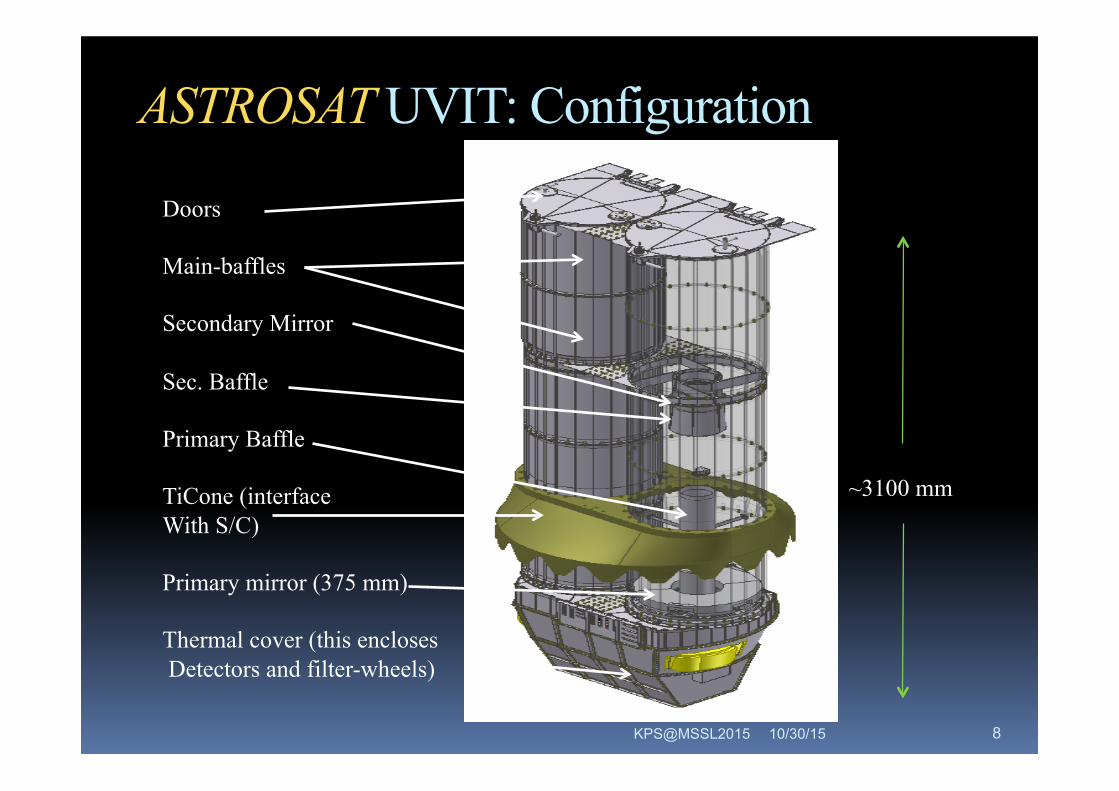
ASTROSAT UVIT: Configuration
Doors
Main-baffles
Secondary Mirror
Sec. Baffle
Primary Baffle
TiCone (interface With S/C)
Primary mirror (375 mm)
Thermal cover (this encloses Detectors and filter-wheels)
~3100 mm
10/30/15 KPS@MSSL2015 8

UVIT:J.HutchngsPASP(2011),123,833EffectiveApertures(estimates)
10/30/15 KPS@MSSL2015 9

UVIT:J.HutchngsPASP(2011),123,833EffectiveApertures(estimates)
10/30/15 KPS@MSSL2015 10

ASTROSATSCIENCE:UVITSimulations
10/30/15 KPS@MSSL2015 11
from the source; a small error in a photon’s actual positionwould cause large fluctuations in the ratio images (Figs. 9Cand 9F).
It is to be noted that although the input GALEX image has acount rate of ∼0:05 counts s!1 per arcsec2 (i.e., 0:015 counts perframe per CMOS pixel, reconstructed images still show signif-icant photometric errors. The reason for this lies in the shape ofcentroid algorithms. During the observations, it is the count ratewithin the centroid algorithm shape that would determine thefraction of double or multiple events and hence the amount
of photometric error in reconstructed images. As an example,for the 3-square algorithm, the sky area within its algorithmshape is 9 pixels, leading to a count rate of ∼0:13 counts perframe. Further, as part of the photon event lies outside the3-square window, for low values of rejection threshold, pho-tometry at any point would be affected by the presence ofphoton events in a larger area. This is evident from the recon-structed images shown in Figure 9. A number of star-forminggalaxies with strong and extended H II regions would be ex-pected to show such photometric errors.
FIG. 8.—The input and simulated images of a Galaxy. Archival ultraviolet image of M51 Galaxy from GALEX data archive is used for simulation. (A) Input image,obtained after applying necessary correction to the archival image; (B) simulated image of the input image, using Poisson statistics. This image is to be processed withinUVIT subsystems. Both the images correspond to 3000 s integration time with the frame rate of 30 frame s!1 and are convolved with Gaussian function with σ of 0.5″.(C) Uncorrected reconstructed image of the same galaxy using 3-square algorithm. The superimposed grid pattern is the modulation pattern discussed in § 3.3 withfrequency of one CMOS pixel. (D) The corresponding corrected image. Pixel scale for all images is 0:5″pixel!1.
630 SRIVASTAVA, PRABHUDESAI, & TANDON
2009 PASP, 121:621–633
M51 galaxy
GALEX (spatial scale reduced to put it at 3 times its distance) vs Astrosat FUV Image From stacking of several short exposure images to correct for drift
PASP (2009), 121, 621

10/30/15 KPS@MSSL2015 12
X-ray timing (10 µsec) low spectral resolution studies
A broad energy band (3 - 80 keV) with high detection efficiency
• Three co-aligned identical Counters
• Each with a multi-wire-multi-layer configuration filled with 90%Xe +10%
Methane gas at 1520 torr. Energy resolution (13%@22 keV)
• A 50 micron thick aluminized Mylar window for X-ray entrance
• Mylar film support -- by a honeycomb shaped window support
collimator with 5 x 5 degs field of view
• A narrow field of view of 1x1 degs provided by mechanical collimators
made of a sandwich of 50µ Sn + 25µ Cu + 100µ Al co-aligned with the
window support collimator and sitting above it.
• Blocking shield on sides and bottom : 1mm Sn + 0.2 mm Cu
LAXPC: Large Area Proportional Counters

ASTROSAT LAXPC
A S T R O S A T H A N D B O O K
54
Details of detector system : Each"LAXPC"consists"of"60"anode"cells"of"3"cm"X"3"cm"cross6section"arranged" in"5" layers"providing"a"15"cm"deep"X6ray"detection"volume."Each"Anode"Layer"thus"has"12"anodes"with"a"total"width"of"36"cm."A"Veto"Layer"made"up"of"46"anode"cells"each"with" cross6section"of"1.5" cm"X"1.5" cm"surrounds" the"main"X6ray"detection"volume"on"3" sides" to" reject" events" due" to" charged"particles" and" interaction"of" high" energy"photons" in" the"detector."The"alternate"anode"cells"of"Layer"1"and"2"are"linked"together"and"thus"4"outputs"are"obtained"from"Layer"1"and"Layer"2.."The"anode"cells"in"each"of"the"Layer"3,"4"and"5"are"linked"together"to"provide"one"output"from"each"layer."Thus"there"are"7"anode"outputs"that""are"operated"in"mutual"anticoincidence"to"reduce"the"non6cosmic"X6ray"background"The"Veto"layer"is"divided"in"3"parts"providing"3"Veto"Layer"outputs."The"left"side"and"right"side"veto"anodes"are"linked"together"to"provide"one"output"from"each"one"and"the"third"veto"output"is"from"the"bottom"layer"veto"anodes"linked"together."""
""A"50"micron"thick"aluminized"Mylar"film"serves"as"the"gas"barrier"as"well"as"the"X6ray"entrance"window"for"the"detector."The"detector"is"filled"with"a"mixture"of"90%"Xenon"+"10"%"Methane"at"a"pressure"of"1520"torr."The"Mylar"window" is" supported" against" the" gas" pressure" by" a" honey" comb" shaped" collimator"made" of" square"
60 anode cells 3 cm x 3 cm x 100 cm in 5 layers each 15 cm deep (12 anodes/layer). Mutual & layer by layer anticoincidence + Veto layers of 46 anodes cells (1.5x1.5 cm) 1600 wires – tension 80 gm per wire
10/30/15 KPS@MSSL2015 13

ASTROSATLAXPCunit(~125Kg)
10/30/15 KPS@MSSL2015 14

SXT:FPCA+Optics(~65Kg)
10/30/15 15 KPS@MSSL2015

SXT:Optics–ReplicatedThinfoilmirrorsmadeinTIFR(followingSuzaku)
10/30/15 16
2 m focal length; ~2 arcmin HPD; 40 shells (130 – 260 mm dia); Only 12 Kg !
Mirror roughness 7 – 10 Angstroms : Exp. Ast. (2011), 28,11
KPS@MSSL2015

10/30/15 17
• Four Fe-55 calibration (corner) sources • One Fe 55 calibration door source • Thin Optical Blocking Filter • CCD Assy. including TEC • PCB with front-end electronics
Modified from Swift; Using spare MOS CCD22 from XMM: 600 x 600 pix, 40 microns
KPS@MSSL2015

ReadoutModesoftheCCD(1) Photon Counting Mode (PC), [The Default Mode - includes the
calibration sources] (2) Photon Counting Window Mode (PCW), (3) Fast/Timing Mode (FM), (4) Bias Map Mode (BM), and (5) Calibration Mode (CM). ! X-ray spectral information available in all the modes. ! Time resolution in the PC, PCW, CM modes is 2.4 s, and 0.278 s in the FM mode. ! FM reads only the central 150x 150 pixels of the CCD. ! For observing very strong cosmic sources, the PCW mode should be used to avoid pile-up followed by the Calibration mode where four small windows (each of size=80 x 80 pixels) covering only the corners are used for the corner radioactive sources in the CM. ( A central 100x100 window is also used in the CM).
10/30/15 18 KPS@MSSL2015

SXT Flight FPCA CCD
Door and Corner X-ray Calibration Sources Optical LED Image
Very good – only 2 hot pixels
10/30/15 KPS@MSSL2015 19

SXTFM:Electronics:NIM:A(2009),604,747;EnergyCalibrationspectrummeasuredusinginternalsources:SinglePixevents,alltypesofevents.CCD@-80C
10/30/15 20
4.5 keV (Ti-F)
4.15, 4.75 keV Mn-K Esc
2.6 keV (CL-F) 1.74 keV
(Si-K)
1.48 keV (Al-F)
KPS@MSSL2015

FMCALIBRATIONat-80C:MeasuredwithInternalFe-55sourcesandresponsemodeled
Target Energy Res. %ge (FWHM, eV) Al –Flo 1487 eV 90 +- 8 6.0+-0.5 Si –K 1740 eV 92 +- 6 5.1+-0.3 Cl –Flo 2621 eV 104+-5 4.0+-0.2 Mn-Kα esc 4155eV 120+-5 2.0+-0.15 Ti -Flo 4511 eV 126+-6 2.8+-0.15 Mn-Kβ esc 4750 eV 128+-7 2.7+-0.15 Mn-Kα 5895 eV 135+-9 2.3+-0.15 Mn- Kβ 6490 eV 140+-10 2.1+-0.15
10/30/15 21 KPS@MSSL2015

Side joining plates
Collimator
CZT top hsg.
CZT bottom hsg.
Radiator
Heat pipes
Optical cube Alpha tag source
Handling brackets
CFRP support
CAM (Tantalum)255 pseudo-random Hadamard
ASTROSAT CZT-Imager Size: 482 x 458 x 603 mm
Weight - 50 kg
Collimator fov: 6o x 6o
Power – 60 Watts
976 cm 2 (64 CZT modules x 15.25 cm2 in 4 quadrants); No. of pixels: 16384; 2.4 mm X 2.4 mm (5 mm thick) ; ASIC based (128 chips of 128 channels)

CZTI: Calibration & Veto ! An X-ray source (Am241) mounted in a gap of 8 cm
between the base of the collimator slats and detector plane in each quadrant for calibration.
! VETO Detector: CsI (Tl) 20 mm thick x 165 mm x 165 mm detector viewed by two photomultipliers in a flat geometry. Just under the CZT modules. " LLD: 50 keV. Variable by command: 256 steps of ~ 10 keV. " Uniformity: ~ 10%, " Response time: 5 µs " Typical dead-time: 20 µs; A few hundred µs for saturated
peaks
10/30/15 KPS@MSSL2015 23
NIM:A (2010), 616, 55

CZTI: Modes ! Normal mode 1s 0-9 packets/quadrant ! SAA mode 100s 1 packet/quadrant ! Shadow mode 100s 1 packet/quadrant ! Reduced data mode
" Fixed no. of events 1s 0-9 packets/quadrant " Block veto spectrum 1s 0-9 packets/quadrant " 2 word event report 1s 0-9 packets/quadrant
! Secondary spectral 100s 2 packets/quadrant
10/30/15 KPS@MSSL2015 24
Charged Particle Monitor – to monitor the SAA entry and exit to lower voltages of the LAXPC CsI + Si-pin photodiode; LLD of 1 MeV & can be reset

CPMdetectsSAA(Oct.1,2015)
10/30/15 KPS@MSSL2015 25

Scanning Sky Monitor (SSM)
A S T R O S A T H A N D B O O K
73
an" SSM" detector." " The" top" layer" consists" of" position6sensitive" anode"wires" surrounded" by" wire6walled" cathode"forming"individual"cells."""Figure"6.4"shows"the"photo"of"the"wire"module"inside"the"detector."
Figure!6.4!:!!Wire!module!kept!inside!the!detector! Principle of Operation:
When" an" X6ray" photon" enters" the" gas"chamber" it" ionizes" the" gas" by" photo6electric"effect"which" leads" to" formation"of"several" electron6ion" pairs." " The" electrons"are" accelerated" towards" the" anode"resulting" in" further" multiplication" of" the"charge"which"is"collected"at"the"anode.""In"a" position6sensitive" detector" the" anode"being" resistive," the" charge" is"proportionately" divided" to" the" two" ends"depending" on" the" position" where" the"charge" cloud" is" collected" along" the" anode"wire.""This"charge"is"converted"into"voltage"using" a" charge" sensitive" preamplifier"
(CSPA)"at"both"the"ends."The"corresponding"voltage"pulses"at"either"ends"of"the"anode"are"referred"to"as"left"(VL)"and"right"(VR)"outputs"of"the"anode."The"total"amplitude"of"both"the"outputs"is"proportional"to"the"energy"of" the" incident" photon." " The" position" (P)" of" the" incident" photon" on" the" detector" plane" is" given" by" P=(VL6VR)/(VL+VR)"*C1+C2,"where"VL"and"VR"are"the"amplitudes"of"the"left"and"right"output"pulses"and"C1"and"C2"are"the"calibration"constants"of"that"particular"anode"on"which"the"photon"is"incident."""The"SSM"detector"plane"consists"of"two"layers"of"wire6cells,"central"eight"of"the"top"layer"being"active"anode"cells."The"two"edge"cells"of"the"top"layer"and"the"ten"cells"in"the"bottom"layer"are"all"connected"together"to"form"the"background"or"veto" layer."The"information"that"we"get"about"every"photon"that" is" incident"on"the"detector"are"1."Time"of"arrival,"2."Energy"and"3."Position"of"incidence.""All"the"three"parameters"are"measured"using"the"electronics"system"of"SSM.""Design of Mask Six"different"coded"mask"patterns"could"be"generated"for"the"constraints"set"in"the"specifications"of"SSM,"with"50%"transparency.""They"are"joined"sideways"and"the"resulting"complete"mask"plate"is"shown"in"figure"4.""The"design" of" the" coded" mask" and" the" deconvolution" software" is" developed" in" collaboration" with" Prof." D."Bhattacharya"of"IUCAA."
Figure!6.5!:!The!coded!mask!plate!with!six!different!mask!pattern!used!in!each!of!the!three!SSM!cameras.!
The image cannot be displayed. Your computer may not have enough memory to open the image, or the image may have been corrupted. Restart your computer, and then open the file again. If the red x still appears, you may have to delete the image and then insert it again.
The image cannot be displayed. Your computer may not have enough memory to open the image, or the image may have been corrupted. Restart your computer, and then open the file again. If the red x still appears, you may have to delete the image and then insert it again.
Three rotating Units: PSPC + coded mask
10/30/15 KPS@MSSL2015 26

AstroSatStatus&SwitchONSequence
! ChargeParticleMonitor(CPM)forSAAmonitoringisONandworking
! LowVoltageSystemsforPEswitchedonforSXT,CZTI&LAXPC:StatusOK
! SXTcameraventinggoingondailyfor10mins
! CZTIHighVoltage-5thOct,andfirstlight–Oct6th(CrabsimultaneouswithSwift)
! SSMOn:12thOct.! SXT:TECONforCCD(Oct9)andTelescopeDooropening(15
Oct)andCameraDoorOpeningandfirstlight(Oct27)
! LAXPCHVONandfirstlight(Oct17)
! UVITON(Nov26th)
10/30/15 KPS@MSSL2015 27

Astrosat–PostlaunchMissionPlan! 1styear
" First6months–PVPhase(4X-ray;2UV)" Next6months–GTPhase(4X-ray;2UV)
! 2ndyear" 5%Canada,3%UK,5%TOO,2%Cal,35%OpenforGO(India),50%Instruments’GT
! 3rdyear" 5%Canada,3%UK,5%TOO,2%Cal,45%OpenforGO(India),30%Instruments’GT,10%OpenforInternationalGO
! 4thyear" 5%Canada,3%UK,5%TOO,2%Cal,65%India(GO),20%InternationalGO
10/30/15 KPS@MSSL2015 28

ASTROSAT – several multi-wave instruments co-aligned for
# SimultaneousOpt-NUV–FUV-softX-ray-hardX-ray
measurements
# LargeX-raybandwidth,betterhardX-raysensitivity
thanRXTE
# LowbackgroundX-raydetectors:nearEquatorial
Launch
# BrightsourcecapabilityinsoftX-rays
# UVimagingcapabilitybetterthanGALEX10/30/15 KPS@MSSL2015 29

ASTROSAT:AcomparisonwithotherX-raySatellites
10/30/15 KPS@MSSL2015 30
Energy (keV)

SciencewithX-rayInstruments! Accretion–WhiteDwarfs(CVs),NeutronStarBinariesandBlackHoles(galactic,extragalactic–AGN).
! Physicsofastronomicaljets(Blazars),magneticfields(Cyclotronlines)etc.
! Physicsofhotcoronalplasmas:HardX-raycomponentsandflares
! Synchrotron,InverseComptonemissionprocesses10/30/15 KPS@MSSL2015 31

ASTROSATSCIENCE:X-raySimulations
10/30/15 KPS@MSSL2015 32
1 10 10010−4
10−3
0.01
0.1
110
norm
aliz
ed c
ount
s s−
1 keV
−1
Energy (keV)
Model: phabs*powerlaw (nH = 6.5E+20 cm−2, Indx = 1.6, Norm = 2.6E−02)ASTROSAT−Simulation 3C454.3 (F)
Exposure: 10 ksCount Rates
SXT: 3.07 ct/sCZTI: 4.4 ct/sLAXPC: 121.7 ct/s
FluxSXT(0.5−10 keV): 1.78E−10 ergs−1 cm−2 s−1
CZTI(10−100 keV): 3.95E−10 ergs−1 cm−2 s−1
LAXPC(3−80 keV): 4.39E−10 ergs−1 cm−2 s−1
Ref: Wehrle et al., ApJ, 758, 72 (2012)
SXT LAXPC
CZTI
1 10 10010−4
10−3
0.0
10.1
110
100
1000
Counts
s−1
keV−1
Energy (keV)
Exposure = 12.5 ks4U 1636−536 (Astrosat)
wabs*(bbodyrad+bbodyrad+comptt)
[Fiocchi et al., ApJ, 651, 416, 2006]
1 1 2
2
3
3
2
3
Black: SXT(0.3−8.0keV): 27.5 cpsRed: LAXPC(3−80keV): 753.4 cpsGreen: CZTI(10−100keV): 1.8 cps
Dotted lines : model components1 : 1st blackbody2 : 2nd blackbody3 : Comptonization
1 10 1000.01
0.1
110
100
Cou
nts
s−1 k
eV−1
Energy (keV)
Exposure = 50 ksHercules X−1 (Astrosat)
wabs*NPEX*cyclabs[Enoto et al., PASJ, 60, 57, 2008]
Black: SXT(0.3−8.0keV): 1.3 cpsRed: LAXPC(3−80keV): 1697.0 cpsGreen: CZTI(10−100keV): 74.3 cps
Histogram: model: wabs*NPEXData points: Simulated data
SED of AGN: Blazars, Seyferts
Simulation XRB, Cyclotron lines from neutron stars in X-ray binaries.
Simulation MCV

Acc. Disks in AGN – UV/X-ray continuum
Laha, GCD, AKK, SC 2013
Mehdipour et al. 2011
OM
HST/COS
Mrk 509
Disk
Disk
FUSE
EPIC-pn
Disk dominated AGN! High/Soft State of AGN!!!
Done et al. 2013 IRAS 13349+2438
PG 1244+026
10/30/15 KPS@MSSL2015 33

Non-ThermalEmissioninClustersofGalaxies:Motivation
10/30/15 KPS@SAAO 2015
The X-ray emitting thermal plasma in a virialized cluster loses most information on how the formation proceeded due to the dissipative processes driving the plasma towards a Maxwell-Boltzmann momentum distribution characterized by its temperature only. Non- equilibrium distributions of cosmic rays preserve the information about their injection and transport processes much better, and thus provide a unique window of current and past structure formation processes. Information about these non-equilibrium processes is encoded in the spectral and spatial distribution of cosmic ray electrons and protons. Radiative loss processes of these non-thermal particle distributions produce characteristic radio synchrotron, hard X-ray inverse Compton, and hadronically induced γ-ray emission.
34

Motivation(contd.)
10/30/15 KPS@SAAO 2015
Non-thermal Radio emission is seen as: Radio Relics: Have a high degree of polarisation, are irregularly shaped and occur at peripheries of the clusters -- can be attributed to merging or accretion shock waves. Radio Haloes: Resemble the regular morphology of the X-ray emitting intra-cluster plasma and are poorly understood. Where is the non-thermal X-ray and γ-ray emission ?
35

Non-thermalprocessesinclusters
10/30/15 KPS@SAAO 2015
Cosmic rays in clusters of galaxies – II. Radio halos, relics, and γ-ray emission 3
Figure 2. Schematic overview over non-thermal radiative processes ingalaxy clusters. Various gravitational and non-gravitational energy sources(shown in red) are able to accelerate relativistic particle populations (shownin blue) by means of different plasma processes (shown in green). Non-thermal cluster observables (shown in yellow) are tracers of these cosmicray populations: any cosmic ray electron population can emit radio syn-chrotron radiation as well as inverse Compton emission that extends fromthe X-ray into the γ-ray regime. In contrast, the characteristic spectral signa-ture accompanying γ-ray emission from hadronic cosmic ray interactions isa unique sign of a cosmic ray proton population in the intra-cluster plasma.
on the pressure of the thermal electron population integrated alongthe line-of-sight through the cluster. Finally, galaxy spectra probedirectly the stellar populations of intra-cluster galaxies and indi-rectly the cluster’s potential through their velocity dispersion (forreviews see Sarazin 1988; Voit 2005).
The lower part of Fig. 1 sketches the cosmic ray physicswithin clusters. CR protons behave differently compared to thethermal gas. Their equation of state is softer, they are able to travelactively over macroscopic distances, and their energy loss time-scales are typically larger than the thermal ones. Besides ther-malization, collisionless shocks are also able to accelerate ionsof the high-energy tail of the Maxwellian through diffusive shockacceleration (for reviews see Drury 1983b; Blandford & Eichler1987; Malkov & O’C Drury 2001). These energetic ions are re-flected at magnetic irregularities through magnetic resonances be-tween the gyro-motion and waves in the magnetised plasma andare able to gain energy in moving back and forth through theshock front. This acceleration process typically yields a CR protonpopulation with a power-law distribution of the particle momenta.CRs are accelerated on galactic scales through supernova shockswhile they are injected by structure formation shock waves on evenlarger scales up to tens of Mpc. So far, we have neglected feed-back from active galactic nuclei (AGN) in our simulations despiteits importance (for first numerical simulations of thermal ‘radio-mode’ feedback within cosmological simulations, see Sijacki &Springel 2006). Gravitational energy associated with the accretiononto super-massive black holes is converted into large-scale jetsand eventually dissipated into thermal and CR energy.
The ubiquitous cosmic magnetic fields couple the otherwisedynamically independent ingredients like the ICM plasma, and theCR gas into a single, however complex fluid. Magnetic fields pre-vent charged relativistic particles to travel macroscopic distanceswith their intrinsic velocity close to the speed of light. Instead,the particles gyrate around, and travel slowly along magnetic field
lines. Occasionally, they get scattered on magnetic irregularities.On macroscopic scales, the transport can often be described as adiffusion process that redistributes the CR energy density macro-scopically provided the gyro-radius of charged relativistic particlescan be regarded to be small. Thus, the diffusive CR transport intangled magnetic fields effectively confines the CRs with energiesE < 2 × 10⁷ GeV to clusters and yields to CR proton lifetimes ofthe order of the Hubble time (Volk et al. 1996; Ensslin et al. 1997;Berezinsky et al. 1997; Colafrancesco & Blasi 1998), long enoughto diffuse away from the production site and to maintain a space-filling distribution over the cluster volume. Thermal heat conduc-tion is an analogous process that reallocates the thermal energy ofthe ICM.
The CR energy reservoir suffers two main loss processes: (1)CR energy is transferred into the thermal energy reservoir throughindividual electron scatterings in the Coulomb field of the CR par-ticle as well as by small momentum transfers through excitations ofquantised plasma oscillations. We refer to the sum of both effectsas Coulomb losses (Gould 1972a). (2) Provided the CR momentumexceeds the threshold p ≃ 0.8GeV/c for the hadronic reaction withambient protons, they produce pions which decay into secondaryelectrons, positrons, neutrinos, and γ-rays:
π± → µ± + νµ/νµ → e± + νe/νe + νµ + νµπ0 → 2γ .
Only CR protons above this kinematic threshold are therefore vis-ible through their decay products via radiative processes, makingthem directly observationally detectable. As shown in Fig. 2, thesesecondary relativistic electrons and positrons can emit a halo ofradio synchrotron emission in the presence of ubiquitous intra-cluster magnetic fields (Dennison 1980; Vestrand 1982; Blasi &Colafrancesco 1999; Dolag & Enßlin 2000; Miniati et al. 2001b;Pfrommer & Enßlin 2003, 2004a,b; Marchegiani et al. 2007) aswell as inverse Compton emission by scattering photons from thecosmic microwave background into the hard X-ray and γ-regime.11Future γ-ray satellites should be able to detect the associatedhadronically induced γ-ray emission resulting from neutral piondecay and allow unambiguous conclusions on the parent CR popu-lation in clusters.
Structure formation shocks can also directly accelerate so-called primary CR electrons giving rise to an irregularly shapedradio and inverse Compton morphology due to the comparativelyshort synchrotron lifetimes of CR electrons of τ ≃ 108 yr. To com-plicate this picture even more, there are other processes that ac-celerate relativistic electrons. Re-acceleration processes of ‘mildly’relativistic electrons (γ ≃ 100 − 300) that are being injected overcosmological timescales into the ICM by sources like radio galax-ies, supernova remnants, merger shocks, or galactic winds can pro-vide an efficient supply of highly-energetic CR electrons. Owingto their long lifetimes of a few times 109 years these ‘mildly’ rel-ativistic electrons can accumulate within the ICM (Sarazin 2002),until they experience continuous in-situ acceleration either via in-teractions with magneto-hydrodynamic waves, or through turbulentspectra (Jaffe 1977; Schlickeiser et al. 1987; Brunetti et al. 2001;Ohno et al. 2002; Brunetti et al. 2004; Brunetti & Lazarian 2007).This gives rise to a third population of re-accelerated CR electronsthat also contributes to the observed radio and inverse Comptonemission. Since the distribution of magnetic field strengths with
11 In the following, we use the term secondary CR electrons synonymouslyfor the likewise produced electrons and positrons.
c⃝ 2003 RAS, MNRAS 000, 1–32
36

HardX-ray(20-80keV)Tails:Balloon+Satellitebasedmeasurements
10/30/15 KPS@SAAO 2015
12
Fig. 3.— The non-thermal signal and 1σ uncertainties in PDS 20 – 80 keV band after subtraction of the contributionsfrom the background, thermal gas and AGN in the field, and after propagating uncertainties due to these subtractions.The dotted vertical line separates the relaxed clusters (left) from the rest (right).
Beppo-SAX: Nevalainen et al. 2003
Relaxed
37

Swift/BAT:JointlywithXMM-Newton
10/30/15 KPS@SAAO 2015
Ajello et al. 2009, 2010
20 Clusters studied: Perseus, A3266, A754, Coma, A3571, A2029, A2142, Triangulum, Ophuchius, A2319; A85, A401, Bullet, PKS 0745-19, A1795, A1914, A2256, A3627 (Norma), A3667, A2390.
All best described by multi-temp thermal model except Perseus and Bullet (4.4σ) which show hard X-ray excess consistent with Chandra Observations for Bullet, and AGN: NGC 1275 in Perseus.
38

Suzaku+XMM:ComaCluster(A1656)
10/30/15 KPS@SAAO 2015
Wik et al. 2009;
Also see: Suzaku observations of X-ray excess emission in the cluster A 3112 T. Lehto et al. 2010 $ Basically: Cannot rule out the presence of NT emission !!
Non-Thermal Emission in the Coma Cluster 7
negligible at energies above 2 keV. In general, we character-ize the dominant thermal emission in XSPEC with the APECmodel for E < 40 keV and with the MeKa model for E > 40keV. In the currect version of XSPEC, the APEC and MeKaLmodels are undefined above 50 keV, though the MeKa andbremsstrahlung models are defined. We tie the parametersof the MeKa model to the APEC parameters, except for theMeKa normalization, which we reduce relative to the APECnormalization by 5.5% to bring the models into agreementat high energies. Also, the abundances relative to solar andthe redshift are fixed, to 0.24 and 0.0232 respectively (see§ 3.2). This value for the abundance is based on fits to the finalweighted and summed XMM spectrum alone, and the best-fitabundances of all the individual spectra from the 10 regionsis also consistent with this value. Since we are interested incontinuum features, the exact choice for the abundance doesnot strongly affect the results. The spectral fitting results aresummarized in Table 2.
4.1. Joint XMM-Newton and Suzaku Spectral Fits WithoutConsidering Systematic Errors
We simultaneously fit the Suzaku HXD-PIN and XMM-Newton EPIC-pn spectra for the PIN FOV. First, we consideronly a single temperature fit, in order to establish whether theaddition of a non-thermal component actually improves the fit(Fig. 4). We find a best fit temperature of 8.45± 0.06 keV,which is in general agreement with similar fits to the PIN data(8.3± 0.3 keV) and XMM data (8.37± 0.12 keV) individu-ally. Note that the dip at 15 keV is a known problem withthe current NXB model (Mizuno et al., Suzaku Memo 2008-0313). Since each spectrum is individually described by thesame average temperature, the existence of excess emissionat hard energies is unlikely. While all of these temperaturesare slightly higher than the cluster-wide average temperatureof 8.2 keV (Hughes et al. 1993), the energy range in this andsimilar fits typically extends to energies below 2 keV and thusincludes more low temperature gas.The addition of a power-law non-thermal component pro-
duces a formally better description of the spectra, accordingto the f-test, improving the overall fit (Table 2), but only for aphoton index Γ < 0. Allowing the temperature and power lawphoton index to vary along with each component’s normaliza-tion, we find T = 8.42± 0.06 keV and Γ = −1.6, though Γ ispoorly constrained. If we fix Γ to this best-fit value, the ICcomponent is significant at the 2.2σ level without consideringthe effect of systematic uncertainties. However, this photonindex is completely inconsistent with the spectral index of theradio halo (Γ
∼> 1.8, Giovannini et al. 1993). While we might
expect a flatter spectrum for IC emission, since the hard X-rayphotons are emitted by somewhat lower energy electrons thanthe radio emission, and the radio spectrum flattens at lowerfrequencies (Thierbach et al. 2003), a rising IC spectrum withenergy is completely unexpected and unphysical. The powerlaw fit, in contrast to finding an actual power law signaturein the data, is instead compensating for a slight excess at highenergieswhile minimizing its impact on the overall fit at lowerenergies. Notice that the residuals in Figure 4 above 40 keVlie systematically, if not significantly, above the model. Thisexcess at energies above 40 keV can be explained as a ∼ 2%underestimate of the NXB, as suggested by the Earth-occultedspectrum (see § 3.1). Increasing the background level by 2%13 http://www.astro.isas.ac.jp/suzaku/doc/suzakumemo/suzakumemo-
2008-03.pdf
FIG. 4.— Suzaku HXD-PIN spectrum (E > 12 keV) and the combinedXMM spectrum (E < 12 keV) corresponding to the spatial sensitivity of thePIN. Shown as solid lines are the best fit models for a single temperaturethermal component. The thermal model (“APEC", green) is nearly coincidentwith the data, though falling below it at higher energies. Also included for alljoint fits are the the total spectrum for the “XMM Point Sources" (red) and theCosmic X-ray Background (“CXB", purple), the latter of which only appliesto the PIN spectrum since the CXB is subtracted from the XMM data alongwith the NXB.
FIG. 5.— Suzaku HXD-PIN spectrum (E > 12 keV) and the combinedXMM spectrum (E < 12 keV) corresponding to the spatial sensitivity of thePIN. Shown as solid lines are the best fit models for a single temperature ther-mal component plus a non-thermal component. The thermal model (“APEC",green) is nearly coincident with the data, though falling below it at higherenergies. The non-thermal model (“Power Law", light blue) is the faintestmodel component for both spectra, and the photon index is fixed at Γ = 2.0.The other two components are described in Figure 4.
for E > 40 keV results in a best-fit power law component verysimilar to the model used for the XMM point sources, withΓ ∼ 1.6, but it is not significant at even the 1σ level. A sim-ilar result is found if the photon index is fixed at Γ = 2 andthe NXB above 40 keV is not increased; this fit is shown inFigure 5. In this case, the fit is not improved by the additionof a power-law component to the model.Interestingly, a two-temperature model for the ICM yields
only a slightly better fit to the data than does the single tem-perature model (see Fig. 6), though the addition of a sec-ond temperature component is probably not formally justi-fied. This result is mainly due to the addition of the 3% sys-tematic error to the XMM spectrum. Without including thaterror, a two-temperature model produces a clearly improvedfit over a single temperature model, indicating that the addi-tion of this error is somewhat obscuring evidence for a multi-temperature continuum. In either case, the two temperaturesare not strongly constrained, but they are broadly consistentwith the spatial variations in Coma’s temperature (see § 4.2
39
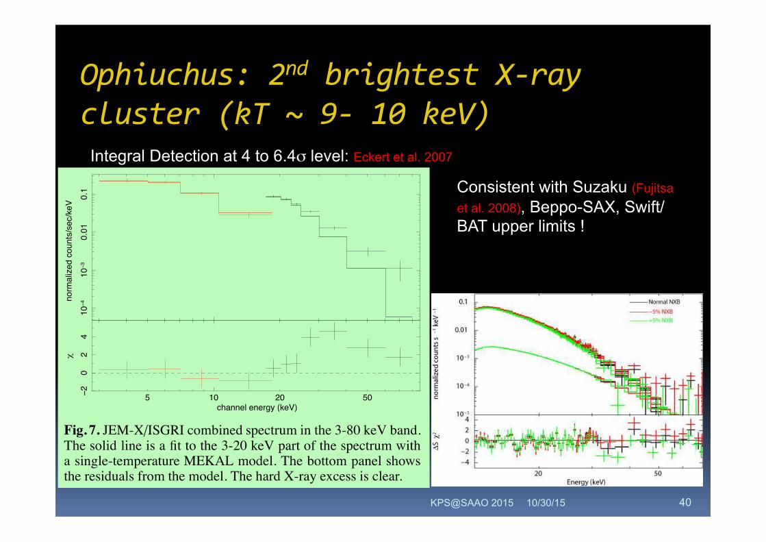
Ophiuchus:2ndbrightestX-raycluster(kT~9-10keV)
10/30/15 KPS@SAAO 2015
Integral Detection at 4 to 6.4σ level: Eckert et al. 2007
Fig. 7. HXD PIN spectra, including the effect of varying the normalization of the NXB by ±5% (crosses).
The NXB has been subtracted. The fit (solid line) is for the normal NXB. The lower panel plots the
residuals divided by the 1σ errors.
than that expected from the BeppoSAX PDS observations (Nevalainen et al. 2004).
We note that the systematic uncertainty in the HXD NXB strongly affects the results.
According to Mizuno et al. (2007), the systematic 1σ uncertainty in the 15–40 keV NXB is
3.2 %. We conservatively adopt a systematic uncertainty of ±5% (90% uncertainty), and
estimate the upper limit on any extra hard X-ray component. Since the uncertainty in the
NXB overwhelms the statistical error on the ICM temperature, we fix the temperature of the
APEC model at 9.0 keV and add a power-law component to represent the extra hard X-ray
emission. We fixed the photon index of the power-law at 2.0, which is the same as that in Eckert
et al. (2008). The 90% upper limit on the hard power-law component is obtained by employing
the NXB spectra for which normalization is 5% lower than the normal NXB. The HXD spectra
including ±5% variations in the normalization of the NXB are shown in figure 7. The upper
limit on the flux of any extra hard X-ray component is 2.8× 10⁻¹¹ erg s−1 cm−2 (20–60 keV),
which is consistent with the detection obtained with INTEGRAL (0.7–1.3×10⁻¹¹ erg s−1 cm−2;
Eckert et al. 2008) and the upper limit from a combined Swift/BAT and Chandra spectrum
(5.2× 10⁻¹³ erg s−1 cm−2; Ajello et al. 2008). If we assume that the temperature of the APEC
model is 8.5 keV as Eckert et al. (2008) did, the upper limit on the flux is 4.1×10⁻¹¹ergs−1cm−2
(20–60 keV). On the other hand, If we assume that the ICM temperature is 9.7 keV (region C;
Table 1), it is 1.0× 10⁻¹¹ erg s−1 cm−2. Note that the higher temperature is closer to the value
found by Ajello et al. (2008).
11
Consistent with Suzaku (Fujitsa et al. 2008), Beppo-SAX, Swift/BAT upper limits !
Eckert D. et al.: INTEGRAL discovery of non-thermal hard X-ray emission from the Ophiuchus cluster 5
on this image that the hard X-ray emission is compatible withthe soft X-ray morphology of the cluster, and is not displaced to-wards any of the weak point sources seen in the Chandra image,which excludes the possibility that these point sources contributein a significant way to the high-energy spectrum.
Fig. 6. 90% error circles for the position of the center of thesource in the 20-24 (red), 24-30 (blue) and 30-40 keV (white)ISGRI mosaic images, overlaid on the JEM-X 3-18 keV image.The yellow cross shows the position of the centroid of the clusterfrom the Chandra image. The black crosses show the position ofthe two brightest X-ray point sources detected in the Chandraimage.
4. Spectral analysis
4.1. INTEGRAL broad band spectrum of the cluster
Since, unlike the case of the Coma cluster, the source is only veryslightly larger than the PSF of ISGRI, we can use the standardOSA 7.0 spectral extraction tool with our time-dependent back-ground maps to get an accurate flux estimation. Starting fromOSA version 7.0, the calibration of ISGRI is now valid downto 17 keV. Because of the large exposure time, we were ableto reach a high signal-to-noise ratio in both JEM-X (3-18 keVband) and ISGRI (17-60 keV band). In the 40-60 keV band, thedetection significance reaches 6σ. In the 60-80 keV band, thesource is marginally detected by ISGRI at the 1.5σ level. It isimportant to note that no cross-calibration factor between ISGRIand JEM-X data was needed for this work. Introducing such afactor in the XSPEC fitting model results in a cross-calibrationof 1.0, which shows the excellent calibration work done by theISGRI and JEM-X teams for the release of OSA 7.0.
Fitting the combined JEM-X/ISGRI data with a single-temperature MEKAL model (Kaastra & Mewe 2000), with theabundance fixed to 0.49 compared to the solar value (Mohr et al.1999) and redshift fixed to z = 0.028 (Johnston et al. 1981), onefinds a bad representation of the data, with a reduced χ2 exceed-ing 2.3. Another spectral component is hence needed to get abetter fit to the data. Fig. 7 shows the combined JEM-X/ISGRI
Table 1. Results of the fitting procedure for a thermal + power-law model, with abundance and redshift values fixed to the litter-ature value and photon index fixed to α = 2.0, similar to the workof Nevalainen et al. (2004). In Method 1, the temperature andthe normalisation of the Bremsstrahlung component are left freewhile fitting. In Method 2, we used the data in the 3-20 keV bandto fix the temperature and normalisation of the thermal compo-nent, and let free only the normalization of the non-thermal com-ponent. a PF−test is the null hypothesis probability when addingthe non-thermal component given by the F-test. b20-60 keV fluxof the non-thermal component, in units of 10−12ergs s−1 cm−2.The errors are quoted at the 1σ level. cConfidence level for thedetection of the non-thermal component.
χ2red PF−testa kT [keV] FluxHXRb CLHXRσc
Method 1 0.93 2 · 10−4 8.56+0.37−0.35 10.1 ± 2.5 4.0
Method 2 1.05 7 · 10−5 8.50+0.48−0.45 8.2 ± 1.3 6.4
10−4
10−3
0.01
0.1
norm
aliz
ed c
ount
s/se
c/ke
V
105 20 50−20
24
χ
channel energy (keV)
Fig. 7. JEM-X/ISGRI combined spectrum in the 3-80 keV band.The solid line is a fit to the 3-20 keV part of the spectrum witha single-temperature MEKAL model. The bottom panel showsthe residuals from the model. The hard X-ray excess is clear.
spectrum and the residuals from the thermal model with tem-perature kT = 8.50 keV fitted to the spectrum below 20 keV.The model exhibits significant residuals above 20 keV, whichcould be due to the presence of an additional non-thermal com-ponent. Similar to Nevalainen et al. (2004), we assume that thenon-thermal component is a power-lawwith a fixed photon indexα = 2.0. Fig. 8 shows the unfolded spectrum with the thermalmodel and an additional power-law component fitted simultane-ously (Method 1). Table 1 shows the results of the fitting proce-dure using such a power-law in addition to the thermal emission,with the plasma temperature let free while fitting (Method 1) andfixed to the value found by fitting independantly the 3-20 keVpart of the spectrum (Method 2), which is expected to be com-pletely dominated by the thermal component. The BeppoSAXclaim (2σ excess at high energies) was obtained by fixing thetemperature to the value obtained from the low-energy spectrum,which is similar to Method 2. Therefore, we can see that the clearexcess (6.4σ) detected with this method in INTEGRAL data ismuch more significant than the value obtained by BeppoSAX.
40

ComaClusterwithAstroSat
10/30/15 KPS@MSSL2015 41

BulletCluster:NuStar(266ks):Wiketal.2014
10/30/15 KPS@SAAO 2015
NuSTAR Observations of the Bullet Cluster 9
Fig. 5.— The ratio of the spectrum (crosses, using the nominalbackground model; all spectra from Figure 3 have been combinedfor clarity) to each model. The red/dark and green/light shaded re-gions are the same as in Figure 4. Although difficult to tell, the 2Tand T+IC models better describe the overall spectral shape from3–20 keV, producing flatter residuals than the 1T model; the whiteline in each plot represents the same data shown as crosses butmore heavily binned to accentuate the broader spectral shape rela-tive to the models. The rise from 20–22 keV is likely a backgroundline(s) imperfectly subtracted; note that the feature is within ourestimated 3σ uncertainty for the background reconstruction.
of solar, consistent with those determined from previ-ous observatories, such as XMM-Newton (0.24 ± 0.04,Petrosian et al. 2006).Although a 1T model can largely explain the detected
emission, a very slight curvature in the residuals of the fitindicates that the spectrum is not of a truly isothermalplasma. Because our sensitivity extends up to higher en-ergies, we can test whether that extra curvature is morelikely to come from the true multi-temperature structureof the cluster or an IC component. The 2T model ap-proximates what is actually a fairly smooth, somewhatbimodal, temperature distribution (e.g., Andersson et al.2007), so the best fit thermal components in this modelonly roughly correspond to the actual temperatures.Even so, the temperatures we find for the two compo-nents are reasonable, with kThigh = 15.3+8.4
−3.6 keV and
kTlow = 5.3+3.4−3.0 keV. Figure 4 shows the relative impor-
tance of the fainter component, with the lower temper-ature accounting for only ∼ 5% of the 3–30 keV flux.The hard spectral tail up to 30 keV is fully consistentwith a thermal spectrum of ∼ 15.3 keV, only a littlehigher than the ambient, non-“bullet” ICM temperatureof ∼ 14 keV seen with Chandra (Govoni et al. 2004) andthe 14.2 keV temperature found here with the 1T model.Given that at a minimum there is recently shocked gasat much higher temperatures (Markevitch 2006), a risein kThigh of this magnitude is not surprising. Also, therange in temperatures for kTlow agrees very well withtemperatures common in both the “bullet” region andnearby (Andersson et al. 2007).
Lastly, we evaluate the likelihood of an IC excess athigh energies with the T+IC model. The near successof the 1T model suggests that if a detectable IC compo-nent lies at harder energies, the thermal emission shouldbe well accounted for by a single temperature compo-nent. We again find a very reasonable temperature ofkT = 13.8+0.5
−0.2 keV, and the resulting 50–100 keV ICflux is (0.58 ± 0.40) × 10−12 ergs s−1 cm2. Again, thethermal component is entirely consistent with that foundwith previous observatories. The IC flux, on the otherhand, falls nearly a factor of 3 below the expected valueof (1.58+0.43
−0.47) × 10−12 ergs s−1 cm2 (Ajello et al. 2010).Unfortunately, the best-fit IC component only surpassesthe thermal component at ∼> 40 keV, where the clusteremission becomes so faint it is lost in statistical fluctu-ations of the background. To first order, the spectrumappears equally well-fit by the addition of a non-thermalmodel as by the addition of another thermal model, andthe statistical significance of the IC component is possi-bly high enough to warrant a detection. The inclusionof systematic uncertainties and a detailed comparison ofthe 2T and T+IC fitting results outlined in the follow-ing subsection, however, preclude us from making such aclaim.
4.2.3. Relative Performance of Each Model
The mean parameter values and statistical errors werereported in Section 4.2.2; however, true uncertaintyranges must include the impact of both statistical andsystematic fluctuations in the background on the fits.The distribution of best-fit temperatures for the threemodels – found using 1000 realizations of the backgroundfor our 4 spectra – are shown in Figure 6, immediatelyillustrating the impact of both background uncertaintiesand the model we choose to use on our ability to evaluatethe spectrum. When the shape of the model is deter-mined by one parameter, as in the 1T case, backgrounduncertainties have only a slight effect on the temperature,creating a spread of only 0.18 keV (compared to the sta-tistical uncertainty of ∼ 0.25 keV). Adding another pa-rameter that more finely controls the broadband shape ofthe model (2T or T+IC cases) allows background fluctu-ations to play a more significant role. For the 2T model,the best-fit temperatures for each component – shown ingreen in the main panel and inset panel of Figure 6 – aremuch more sensitive to background fluctuations than ineither the 1T or T+IC cases, mostly owing to the greaterflexibility of the model to adjust to small changes in theshape of the spectrum. Background variations primarilyaffect the kThigh component, since a slightly higher/lowerbackground will cause the spectrum to turn over at alower/higher energy, thus pushing kThigh to lower/highervalues. The kTlow component then adjusts to “correct”the low energy part of the spectrum; the two tempera-tures are strongly correlated for a given fit, such that ahigher than typical kThigh will have a higher than typicalkTlow.In the T+IC model, the temperature component dom-
inates at all relevant energies and thus maintains theprecision of the 1T model’s temperature (despite havinga larger statistical error of 0.35 keV). The IC flux, inprinciple, should be much more sensitive to backgroundsystematics than to statistical uncertainties, for the sim-
Very hot kT ~ 15.3 keV, and no evidence for a NT component above 20 keV 42

Chandra:TheBulletClusternon-thermalsurfacebrightnessandPLindex
10/30/15 KPS@SAAO 2015
8 E. T. Million and S. W. Allen
Figure 2. (a) left panel: Spatial map of the surface brightness (in erg cm�2s�1arcsec2) of non-thermal-like X-ray emission in the BulletCluster, 1E 0657-56 (z = 0.297). A power-law component is only included in regions where it is statistically required at greater than90 per cent significance (Section 3.2). The 1.34 GHz radio surface brightness contours from Liang et al. (2000) are overlaid in black.(Radio point sources have been removed). (b) right panel: Map of the photon index of the power-law components, with the radio surfacebrightness contours overlaid. Only regions with ‘non-thermal’ surface brightness greater than 10�16 ergs s�1 cm�2 arcsec�2 are shownin this map. Each spatial region has ⇠ 104 net counts in the 0.6� 7.0 keV Chandra band.
eter). The nominal temperatures of the additional emissioncomponents are typically high, with kT2 ⇠> 15 keV.
As discussed in Section 3.2, the majority of the con-trol sample of relaxed, non-radio halo clusters (all, excludingAbell 576) are known to contain strong temperature gradi-ents in their (cooling) cores. The presence of such gradientswill naturally lead to requirements for additional tempera-ture components in fits to projected spectra for the centralregions of these systems. To mitigate this e↵ect, for the anal-ysis of the control sample of clusters with model D, we haveexcluded the inner 100h�1
70 kpc radius. (The reduced numberof regions studied are indicated in column 4 of Table 3.) Ofthe control sample, Abell 2029 presents a mild requirementfor additional temperature components, and Abell 1795 amore significant requirement, with most of the signal aris-ing from within radii ⇠ 200h�1
70 kpc in both cases. Possibleorigins for these requirements are discussed in Section 5.
Finally, to gauge the level at which residual instrumentcalibration issues may a↵ect the results, we have repeatedthe analysis in three other energy bands: 0.6 � 4.0 keV,0.6 � 5.0 keV and 2.0 � 7.0 keV. For the merging, radiohalo clusters, similar detections of additional emission com-ponents are made using each energy band. The control sam-ple of regular, non-radio halo clusters provides comparablenull results in all energy bands studied.
3.2 Detailed spatial mapping of the ‘non-thermal’components
The results of Section 3.1 provide a simple, statistical mea-sure of the overall significance of non-thermal-like emissionsignatures in the clusters. However, even where these overallsignatures are strong, as in 5/7 of the radio halo clusters, wedo not necessarily expect power-law emission components tobe present in every region in the clusters. We have thereforeattempted to map the spatial variation of this emission.
Starting with model A, a single temperature model withthe absorption fixed at the Galactic HI value, we have de-termined, for each individual region of each cluster, the sta-tistical significance of the improvement to the fit obtainedby introducing a power-law component with a photon indexthat is allowed to fit freely in that region. Where the signif-icance of the improvement was found to exceed a thresholdvalue (we adopt 90 per cent) the power-law component waskept in the model for that region.7 Where it was not, modelA (single, thermal emission component only) was used as theappropriate region model. In this way, the number of regionsrequiring power-law emission components in each clusterwere determined. Finally, the overall absorbing column den-sity was allowed to vary and checked for consistency againstGalactic HI survey results.8 Maps of the surface brightness
7 We have constrained the metallicity to lie within ±50 per centof the value determined with model A. Similar results are alsoobtained if the metallicity is simply constrained to be less thansolar.8 An alternative algorithm to identify regions requiring power-
c� 0000 RAS, MNRAS 000, 000–000
43

Chandra:TheBulletCluster
10/30/15 KPS@SAAO 2015
RESULT:
Spatial correlation between the regions of the brightest non-thermal radio halo emission, brightest thermal X-ray emission, and strongest non-thermal-like X-ray signatures
in the central regions of 1E 0657-56
44

Summary&Challengesahead
10/30/15 KPS@SAAO 2015
The presence of non-thermal hard X-ray emission in clusters of galaxies remains controversial. Existing limits on this component suggest a small magnetic field of the order of 0.1µG, which is in stark contrast to the Faraday rotation measurements which demand much stronger intracluster magnetic field of order of a few µG (Clarke,Kronberg,Bo hringer,2001;Carilli and Taylor,2002). Several possible explanations: Two most likely options in this regard could be the simplest ones: either the reports of detections of nonthermal X-rays are not correct, or they are correct but the nonthermal X-rays are not of IC origin.
To establish the presence or absence of this component, we will need: Hard X-ray telescopes with: High Spatial resolution,
Wide field, Low-to-medium energy/spectral resolution & Large area
45
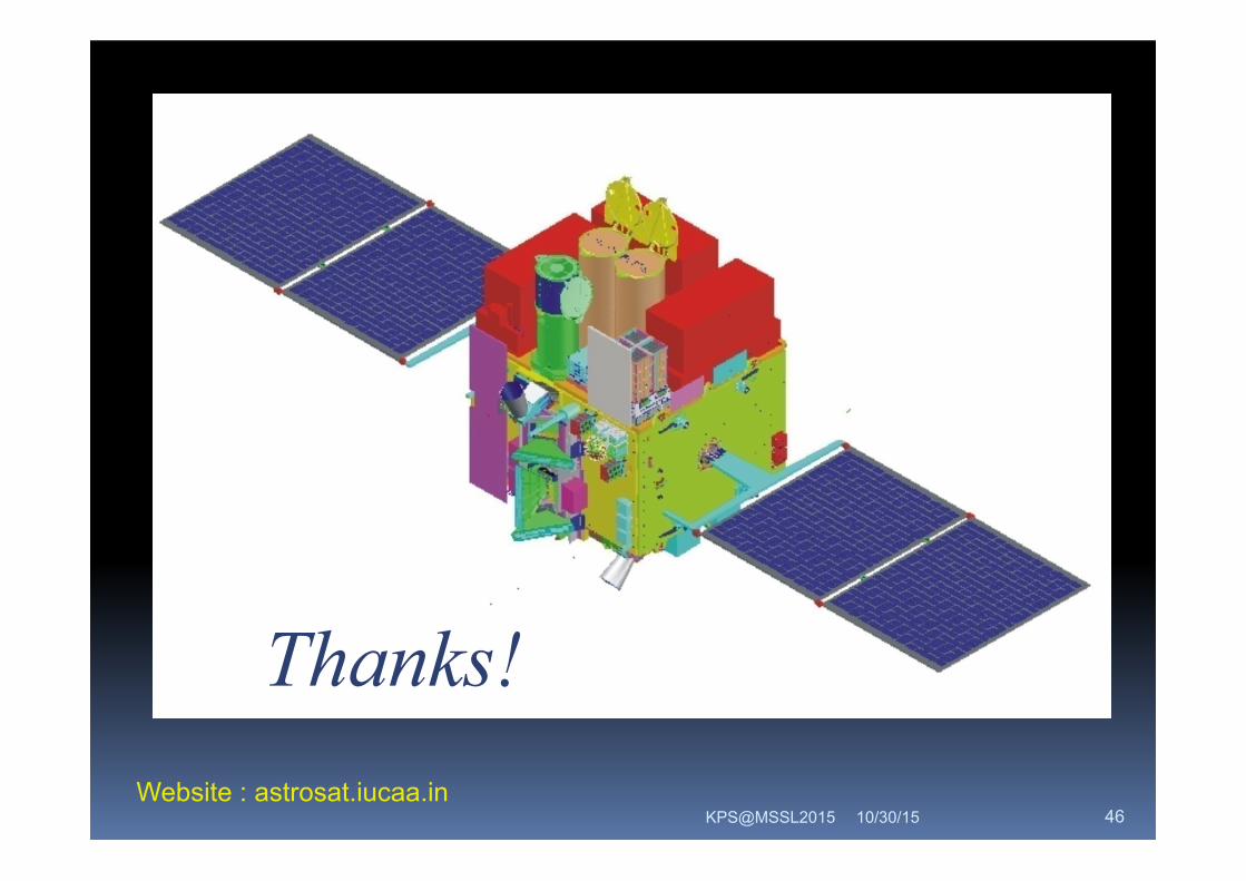
10/30/15 KPS@MSSL2015 46
Thanks! Website : astrosat.iucaa.in