astrosat mission - astrosat.iucaa.inastrosat.iucaa.in/astrosat_spie_2014_kpsingh.pdf · astrosat is...
TRANSCRIPT

ASTROSAT Mission
Kulinder Pal Singh*a, S. N. Tandonb,g, P. C. Agrawalc, H. M. Antiaa, R. K. Manchandad, J. S. Yadava, S. Seethae, M. C. Ramadevif , A. R. Raoa, D. Bhattacharyag, B. Paulh, P. Sreekumarb, S.
Bhattacharyyaa, G. C. Stewarti , J. Hutchingsj , S. Annapurnib, S. K. Ghosha, J. Murthyb, A. Patib, N. K. Raob, C. S. Stalinb, V. Girishf, K. Sankarasubramaniand, S. Vadawalek, V. B. Bhaleraog, G. C.
Dewangang, D. K. Dedhiaa, M. K. Hingara, T. B. Katocha, A. T. Kotharea, I. Mirzaa, K. Mukerjeea, H. Shaha, P. Shaha, R. Mohanb , A. K. Sangalb, S. Nagabhusanab, S. Sriramb, J. P. Malkara, S. Sreekumarl, A. F. Abbeyi, G. M. Hansfordi, A.P. Beardmorei, M. R. Sharmaf, S. Murthyf, R.
Kulkarnif, G. Meenaf, V. C. Babuf and J. Postmam. aTata Institute of Fundamental Research, 1 Homi Bhabha Road, Colaba, Mumbai 400005, India; bIndian Institute of Astrophysics, Bengaluru, India; cCentre for Excellence in Basic Sciences, University of Mumbai, Mumbai; dDepartment of Physics, University of Mumbai, Mumbai; eIndian Space Research Organization, Bengaluru, India; fISRO Satellite Centre, Bengaluru; gInter-University Centre for Astronomy & Astrophysics, Pune; hRaman Research Institute, Bengaluru; iDepartment of Physics & Astronomy, University of Leicester, UK; jNational Research Council of Canada, Victoria, Canada; kPhysical Research Laboratory, Ahmedabad, India; l Vikram Sarabhai Space Centre, Thiruvanatapuram, mUniversity of Calgary, Canada.
ABSTRACT
ASTROSAT is India’s first astronomy satellite that will carry an array of instruments capable of simultaneous observations in a broad range of wavelengths: from the visible, near ultraviolet (NUV), far-UV (FUV), soft X-rays to hard X-rays. There will be five principal scientific payloads aboard the satellite: (i) a Soft X-ray Telescope (SXT), (ii) three Large Area Xenon Proportional Counters (LAXPCs), (iii) a Cadmium-Zinc-Telluride Imager (CZTI), (iv) two Ultra-Violet Imaging Telescopes (UVITs) one for visible and near-UV channels and another for far-UV, and (v) three Scanning Sky Monitors (SSMs). It will also carry a charged particle monitor (CPM). Almost all the instruments have qualified and their flight models are currently in different stages of integration into the satellite structure in ISRO Satellite Centre. ASTROSAT is due to be launched by India’s Polar Satellite Launch Vehicle (PSLV) in the first half of 2015 in a circular 600 km orbit with inclination of ~6 degrees, from Sriharikota launching station on the east coast of India. A brief description of the design, construction, capabilities and scientific objectives of all the main scientific payloads is presented here. A few examples of the simulated observations with ASTROSAT and plans to utilize the satellite nationally and internationally are also presented.
Keywords: X-rays and UV, X-ray Telescopes, UV Telescopes, X-ray and UV Detectors, ASTROSAT, Astronomy Satellite
1. INTRODUCTION A remarkable progress has been made in X-ray and Ultraviolet (UV) astronomy in the last 5 decades with the launch of an impressive array of detectors and telescopes on several satellite missions. These windows provide an incisive insight into the radiation mechanisms and the environments of cosmic sources. Understanding the radiation from these sources, however, requires a wide coverage over the entire electromagnetic spectrum. Since these radiations are also variable on a variety of time scales, simultaneous measurements over a wide range of wavelengths have become one of the essential requirements. ASTROSAT with its suite of several co-aligned instruments has been designed to fulfill this requirement. It is designed to carry wide-band X-ray instruments with overlapping energy response and UV detectors for simultaneous
*[email protected]; phone 91 22 2278 2376; fax 91 22 2280 4610; www.tifr.res.in

spectral and temporal studies to identify and quantify contributions of different components (e.g. thermal, non-thermal, black body, synchrotron, inverse-Compton, spectral lines) in X-ray sources, and thus to understand their nature and astrophysical processes in them. UV imaging of normal, starburst and dwarf galaxies in the local and the distant universe is needed to address the evolution of stellar populations. There are no other international observatories planned in the near future that can cover the entire X-ray spectral band from 0.3 to 100 keV and the UV bands from 1300 - 3000 Angstroms in one mission. Equipped with instruments in these bands, ASTROSAT will thus be a unique mission to address a host of scientific issues in X-ray and UV astronomy.
ASTROSAT is India’s first multi-wavelength astronomy satellite planned for launch in the first half of 2015. The satellite is based on Indian Remote Sensing (IRS) spacecraft. It will be launched into a circular 600 km orbit with inclination of ~6 degrees using the Polar Satellite Launch Vehicle (PSLV). ASTROSAT will have a nominal lifetime of about 5 years. Operations will be with 5-6 ground station contacts per day. Equipped with magnetic torquers and 2 star trackers, ASTROSAT will have target acquisition accuracy of about 30 arcsec. The spacecraft will carry five principal scientific payloads: (i) a Soft X-ray Telescope (SXT), (ii) three Large Area Xenon Proportional Counters (LAXPCs), (iii) a Cadmium-Zinc-Telluride Imager (CZTI), (iv) an Ultra-Violet Imaging Telescope (UVIT) configured as two independent telescopes, and (v) a Scanning Sky Monitor (SSM). A summary of the basic scientific performance parameters of these payloads is given in Table 1. A schematic diagram of the satellite (in stowed position) with all the payloads is shown in Figure 1.
Figure 1: ASTROSAT in stowed position.
2. BASIC SCIENTIFIC PERFORMANCE PARAMETERS The basic performance parameters of ASTROSAT are listed in Table 1. Imaging in the ultra-violet regime has a spatial resolution of 1.8” (~3 times better than GALEX) in a fairly wide field of ~ 28’. The effective area of LAXPC for
LAXPC (TIFR)
UVIT (IIA)
SXT (TIFR)
CZTI (TIFR)
SSM (ISRO)
Star Sensors
Radiator Plate (SXT)

energies above 30 keV is several times larger than that of the RXTE, making it the most sensitive detector in the energy range of 30 – 80 keV. The LAXPC has the highest time resolution of all the ASTROSAT instruments. It is also more sensitive to the detection of Fe lines in the 6 – 7 keV energy band than the SXT, though with a lower energy resolution. SSM will scan a large portion of the sky every few hours to detect and locate transient X-ray sources in the outburst phase, in the 2.5 -10 keV energy range.
Table 1. Performance parameters of ASTROSAT
UVIT
SXT
LAXPC
CZTI
SSM
Detector
Intensified CMOS, used in photon
counting mode or integration mode
X-ray (MOS) CCD at the focal plane.
(XMM & Swift heritage)
Proportional counter
CdZnTe detector array
Position-sensitive
proportional counter
Imaging / non-imaging
Imaging Imaging Non-imaging Imaging Imaging
Optics Twin Ritchey-Chretian 2 mirror
system.
Conical foils (~Wolter-I) mirrors.
2-m focal length
Collimator 2- D coded mask
1- D coded mask
Bandwidth
1300-5500 Angstroms
0.3 - 8 keV 3 - 80 keV 10 - 100 keV 2.5 - 10 keV
Geometric Area (cm2)
~1100
~250
10800 1024 ~180
Effective Area (cm2)
8 - 50 (depends on filter)
[email protected] keV ~22@6 keV
8000@5-20 keV
1000 (E>10 keV)
~11 @ 2 keV ~53 @ 5 keV
Field of View (FWHM)
28’ dia ∼ 40’ dia 10 x 10 60 x 60 100 x 900
Energy Resolution
<1000 A (depends on filter)
∼5-6%@1.5 keV
∼2.5%@6keV
12%@22 keV
5% at 100 keV
25% @ 6 keV
Angular Resolution
1.8 arcsec (FUV,NUV)
2.2 arcsec (Vis)
∼2 arcmin (HPD)
~(1-5) arcmin (in scan
mode only)
8 arcmin
~12 arcmin
Time resolution 1.7 ms 2.4 s, 278 ms 10 μs 1 ms 1 ms
Typical observation
time per target
30 min 0.5 - 1 day 1 - 2 days 2 days 10 min
Sensitivity (Obs. Time)
Mag. 20 (5σ) 200 s
(130-180 nm)
~10-13 ergs cm-2 s-1
(5 σ) (20000 s)
0.1 milliCrab (3σ)
(1000 s)
��� milliCrab (3σ)
(1000s)
~28 milliCrab (3σ)
(600s)
3. SCIENTIFIC INSTRUMENTS 3.1 Soft X-ray Telescope (SXT)
SXT consists of a set of coaxial and con-focal shells of conical mirrors approximating paraboloidal and hyperboloidal shapes and arranged behind each other in a geometrical arrangement known as approximate Wolter I optics. X-rays are first reflected by an internally reflecting paraboloidal (1α) mirror and then reflected to the prime focus of the telescope by the internally reflecting hyperboloid (3α) mirror. Nesting of Wolter I shells is incorporated to improve the effective area. SXT has 40 complete shells of mirrors assembled quadrant-wise (total of 320 mirrors) for 1α and 3α mirrors in a grooves and spokes arrangement similar to that used in the Danish X-ray telescope made for Spectrum-X-Gamma1 and as
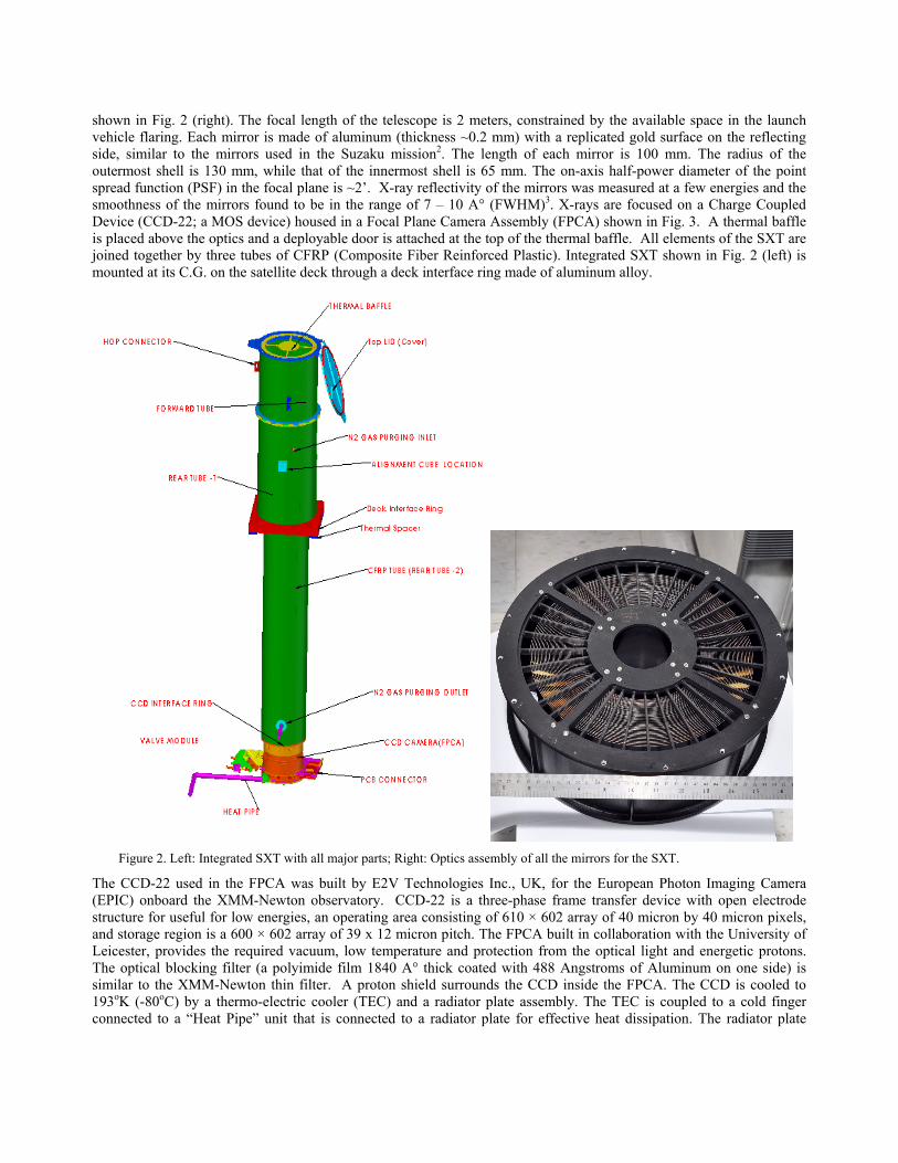
shown in Fig. 2 (right). The focal length of the telescope is 2 meters, constrained by the available space in the launch vehicle flaring. Each mirror is made of aluminum (thickness ~0.2 mm) with a replicated gold surface on the reflecting side, similar to the mirrors used in the Suzaku mission2. The length of each mirror is 100 mm. The radius of the outermost shell is 130 mm, while that of the innermost shell is 65 mm. The on-axis half-power diameter of the point spread function (PSF) in the focal plane is ~2’. X-ray reflectivity of the mirrors was measured at a few energies and the smoothness of the mirrors found to be in the range of 7 – 10 A° (FWHM)3. X-rays are focused on a Charge Coupled Device (CCD-22; a MOS device) housed in a Focal Plane Camera Assembly (FPCA) shown in Fig. 3. A thermal baffle is placed above the optics and a deployable door is attached at the top of the thermal baffle. All elements of the SXT are joined together by three tubes of CFRP (Composite Fiber Reinforced Plastic). Integrated SXT shown in Fig. 2 (left) is mounted at its C.G. on the satellite deck through a deck interface ring made of aluminum alloy.
Figure 2. Left: Integrated SXT with all major parts; Right: Optics assembly of all the mirrors for the SXT.
The CCD-22 used in the FPCA was built by E2V Technologies Inc., UK, for the European Photon Imaging Camera (EPIC) onboard the XMM-Newton observatory. CCD-22 is a three-phase frame transfer device with open electrode structure for useful for low energies, an operating area consisting of 610 × 602 array of 40 micron by 40 micron pixels, and storage region is a 600 × 602 array of 39 x 12 micron pitch. The FPCA built in collaboration with the University of Leicester, provides the required vacuum, low temperature and protection from the optical light and energetic protons. The optical blocking filter (a polyimide film 1840 A° thick coated with 488 Angstroms of Aluminum on one side) is similar to the XMM-Newton thin filter. A proton shield surrounds the CCD inside the FPCA. The CCD is cooled to 193οK (-80oC) by a thermo-electric cooler (TEC) and a radiator plate assembly. The TEC is coupled to a cold finger connected to a “Heat Pipe” unit that is connected to a radiator plate for effective heat dissipation. The radiator plate

provides a maximum temperature of −40°C at the junction between the heat pipe and the camera cryostat. Five individual Fe55 radioactive calibration sources are provided in the camera. Four of these illuminate the four corners (outside the field of view) of the CCD and will be used for in-flight calibration at two principal line energies of ~5.9 & 6.5 keV energies (Fig. 3). The fifth source is under the door that seals the FPCA with vacuum inside, and thus will be ineffective once the FPCA door is opened in orbit in one time operation. The on-axis (and at a few off-axis angles) effective area of the telescope, including CCD Quantum Efficiency (for isolated and bi-pixel events 1-4) and including absorption by the optical blocking filter, is shown as a function of energy in Figure 4.
Figure 3. Left: A schematic of the Focal Plane Camera Assembly (FPCA); Right: Two sets of spectra (in red and black) of
internal calibration sources taken during the thermo-vac tests (Fe55) showing the energy resolution of the FPCA. The lines observed are Mn-Kα (5895 eV, Mn-Kβ (6490 eV), Mn-Kα-escape (4155 eV), Mn-Kβ-escape (4750 eV), Ti-K (4511 eV), Cl-K(2621 eV), Si-K(1740 eV) & Al-K (1487 eV.
Figure 4. Effective Area of the SXT (Left: Log scale; Right: Linear scale).
The SXT electronics4 box consists of ten PCBs containing three Field Programmable Gate Arrays (FPGAs). The electronics, built in house in TIFR, controls the CCD, its temperature, door operation and vacuum/pressure and provides the interface to the telemetry and tele-command sub-systems. Data from the SXT CCD will be stored onboard, and later sent to the ground station once in each orbit of the satellite. The SXT onboard memory quota is 280 Megabytes per orbit (~ 90 minutes). This puts constraints on the data modes and how the data are packaged. There are six data modes for the SXT: "Photon Counting" (PC) mode, "Photon Counting Window" (PCW) mode, "Fast Windowed Photon Counting" (FW) mode, "Bias Map" (BM) mode, "Calibration" (Cal) mode and "House Keeping" (HK) mode. In each mode, data will be packed in 2 Kbyte (2K) segments. So the SXT memory per orbit will be filled with ~143360 blocks each of 2K size. In the PC mode, data from the entire CCD will be collected but only those events that are above specified threshold energy (provided by tele-command; default value between 100 - 200 eV) only will be transmitted. The readout time of this mode is ~2.4 s. The PCW mode is similar to the PC mode, but the data are collected from a smaller rectangular or
square window defined set anywhere on the CCD by the user and uploaded by a tele-command. In the FW mode, a fixed window of 150 x 150 pixels centered on the CCD will be used. The readout time of this mode will be approximately 278 ms. The data of the FW mode will have events above an energy threshold as in the PC mode. The Cal mode will be used to check the calibration of SXT using the radioactive sources shining on the four corners of the CCD. BM mode is a separate mode in which the entire CCD frame will be sent without any threshold.
3.2 Ultra-Violet Imaging Telescope (UVIT)
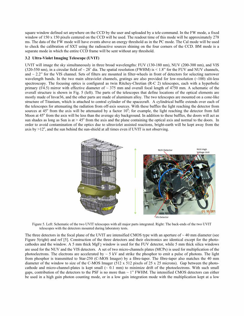
UVIT will image the sky simultaneously in three broad wavelengths: FUV (130-180 nm), NUV (200-300 nm), and VIS (320-550 nm), in a circular field of ~ 28’ dia. The spatial resolution (FWHM) is < 1.8” for the FUV and NUV channels, and ~ 2.2” for the VIS channel. Sets of filters are mounted in filter-wheels in front of detectors for selecting narrower wavelength bands. In the two main ultraviolet channels, gratings are also provided for low-resolution (~100) slit-less spectroscopy. The focusing optics is configured as twin Ritchey-Chretian (R-C 2) telescopes, each with a hyperbolic primary (f/4.5) mirror with effective diameter of ~ 375 mm and overall focal length of 4750 mm. A schematic of the overall structure is shown in Fig. 5 (left). The parts of the telescopes that define locations of the optical elements are mostly made of Invar36, and the other parts are made of aluminum alloy. The two telescopes are mounted on a cone-like structure of Titanium, which is attached to central cylinder of the spacecraft. A cylindrical baffle extends over each of the telescopes for attenuating the radiation from off-axis sources. With these baffles the light reaching the detector from sources at 45o from the axis will be attenuated by a factor 109; for example, the light reaching the detector from full Moon at 45o from the axis will be less than the average sky background. In addition to these baffles, the doors will act as sun shades as long as Sun is at > 45o from the axis and the plane containing the optical axis and normal to the doors. In order to avoid contamination of the optics due to ultraviolet assisted reactions, bright-earth will be kept away from the axis by >12o, and the sun behind the sun-shield at all times even if UVIT is not observing.
Figure 5. Left: Schematic of the two UVIT telescopes with all major parts integrated. Right: The back-ends of the two UVIT
telescopes with the detectors mounted during laboratory tests.
The three detectors in the focal plane of the UVIT are intensified CMOS type with an aperture of ~ 40 mm diameter (see Figure 5(right) and ref [5]. Construction of the three detectors and their electronics are identical except for the photo-cathodes and the window. A 5 mm thick MgF2 window is used for the FUV detector, while 5 mm thick silica windows are used for the NUV and the VIS detectors. A set of two micro-channels plates (MCPs) is used for multiplication of the photoelectrons. The electrons are accelerated by ~ 5 kV and strike the phosphor to emit a pulse of photons. The light from phosphor is transmitted to Star-250 (C-MOS Imager) by a fibre-taper. The fibre-taper also matches the 40 mm diameter of the window to size of the C-MOS Imager (512 x 512 pixels of 25 x 25 microns). Gap between the photo-cathode and micro-channel-plates is kept small (~ 0.1 mm) to minimize drift of the photoelectrons. With such small gaps, contribution of the detectors to the PSF is no more than ~ 1” FWHM. The intensified CMOS detectors can either be used in a high gain photon counting mode, or in a low gain integration mode with the multiplication kept at a low
g
Doors Main-baffles Secondary Mirror Sec. Baffle Primary Baffle TiCone (interface With S/C) Primary mirror (375 mm) Thermal cover (this encloses Detectors and filter-wheels)
~3100 mm
VIS-Detector
NUV-Detector NUV-HighVoltage Unit

value where the raw frame of CMOS is transmitted (in which signal in a pixel of the CMOS detector could be contributed by multiple photons). Typically the UV detectors are used in photon counting mode and the visible detector in integration mode. Either the entire array of 512 x 512 pixels can be read (max. rate of ~29 frames/s), to capture the full field, or a part of the field can be read in “window” mode at rates up to ~600 frames/s, depending on area of the window. The effective areas as a function of the wavelengths have been estimated for all the filters and telescopes and are shown in Figure 6.
Figure 6. Effective areas of UVIT channels with various filters. Top: Visible channel; Bottom left: NUV channel; Bottom
right: FUV channel.
3.3 Large Area Xenon Proportional Counter (LAXPC)
LAXPC consists of 3 identical proportional counters (PCs). Each PC has its own independent front-end electronics, HV supply, and signal processing electronics. Each PC (Figures 7 and 8) consists of 60 anode cells of size 3x3x100 cm arranged in 5 layers providing a 15 cm deep X-ray detection volume. Each anode layer has 12 anodes. A Veto layer made up of 46 anode cells each with a cross-section of 1.5 x 1.5 cm surrounds the main X-ray detection volume on 3
350 400 450 500 5500
10
20
30
40
50VIS1VIS2VIS3BK7ND X 10
Wavelength (nm)
VIS
200 250 3000
10
20
30
40
50NUVB13NUVB4NUVB15NUVN2Silica
Wavelength (nm)
NUV
130 140 150 160 170 1800
5
10
15
Silica
Sapphire
Wavelength (nm)
FUV

sides to reject events due to charged particles and interaction of high energy photons in the detector. The alternate anode cells of layer 1 (and layer 2) are linked together and thus 4 outputs are obtained from layer 1 (and layer 2). The anode cells in each of the remaining three layers are linked together to provide one output from each layer. Thus, there are 7 anode outputs that are operated in mutual anticoincidence to reduce the non-cosmic X-ray background. The Veto layer is divided in 3 parts providing 3 outputs. The left side and right side veto anodes are linked together to provide one output from each side and the third veto output is from the bottom layer veto anodes linked together. An aluminized Mylar film of 50 microns thickness serves as the gas barrier as well as the X-ray entrance window for the detector. The detector is filled with a mixture of 90% Xenon + 10 % Methane at a pressure of 1520 torr. A gas purifier system through which the gas will be recycled regularly is a part of each LAXPC. The window is supported against the gas pressure by a honeycomb shaped collimator made of aluminum cells in a square geometry and called Window Support Collimator (WSC). The field of view (FOV) of the LAXPC is 1o x 1o defined by a multilayer collimator of tin, copper and aluminum placed in a collimator housing and aligned with the openings in the WSC. A 1 mm thick tin sheet coated with copper surrounds each LAXPC unit and serves as the shield for X-rays entering the detector from the sidewalls.
Figure 7. Schematic drawing of a LAXPC showing its various parts.
Low energy threshold (LLD) of LAXPC has been set as 3 keV and the upper threshold (ULD) will be ~80 keV. Since Xe gas has very high fluorescence efficiency, for X-rays with energy above the K-edge of Xe, the K-electron may be ejected and the ion can radiate K X-rays in energy range 29.4–34.4 keV. These X-rays may escape from the detector or be absorbed in a different anode. In order to include these events the anti-coincidence logic is modified to detect this energy range. If two anodes register an event and at least, one of them is in the range of 25–35 keV, then the energy of the two anodes are added and the event is registered. The lower threshold for this (KLLD) and the upper threshold (KULD) can be set through tele-command. Both the gas gain of each LAXPC detector and various threshold values can be set by tele-commend at any time throughout the mission life. Each channel and layer of LAXPC has been calibrated using Fe55, Cd109 and Am241 radioactive sources and a low activity radioactive source shining on the anti layers will be used to monitor the gas gain and energy resolution. The energy resolution, after combining all the detection layers is ~23% at 5.9 keV, ~13% at 22.1 keV and 59.6 keV. The total effective area as a function of energy has been estimated using GEANT4 simulation and is shown in Figure 9 [ref 6].
In normal operation of LAXPC there will be two modes running simultaneously: (a) Broad Band Counting (BBC) that records the event rates in various energy bands in a selectable time bin (8msec to 1024msec; default value 64 msec). There are 15 counters for the broad band counting of the valid X-ray events in different energy bands covering 3-80 keV from all layers; (b) Event Mode Data that records the arrival time of each event with an accuracy of 10 μsec, energy and identity�of each event. This mode generates 5 bytes data for each analyzed and accepted event. In addition, there is a fast counter mode in which the event rate is measured only from the top layer of each LAXPC detector in 4 energy channels covering 3-20 keV band with a fixed time bin of 160 microsecond. This mode has a dead time of ~10 μsec. Each of the 4 counters is 8 bit deep and will cover 3-6, 6-8, 8-12 and 12-20 keV energy bands. This mode will be used for studying rapid variability during the short duration flares or outbursts of sources.

Figure 8.
Figure 9.
3.4 Cadmiu
The charactermodules of ardimensions oshown in Fignearly paralledesign of the is made of a through. The matching theplaces withinexposure to thother angles onoise Hadam
One fully assem
Effective Area
m-Zinc-Tellu
ristics of the Crea 15.25 cm2
of the CZTI argure 10. A pael X-rays to eCAM for the 0.5 mm thicCAM forms t size of the d
n the pattern the full mask ponly a part of
mard Set Unifo
mbled and teste
a of all the 3 LA
uride Imager
CZT-Imager a2 each. These 6re 603.5mm x
assive collimatenter the deteCZTI is suchk Tantalum pthe topmost p
detector pixelsto improve itspattern is not f the shadow oormly Redund
ed LAXPC unit
AXPC units com
(CZTI)
are given in T64 modules arx 482mm andtor (FOV of 4ector. A Codeh that the size plate in whichpart of CZTI ps. Additional s mechanical possible anywof the mask fa
dant Arrays. O
on a vibration
mbined. Effecti
Table 1. It hasre arranged in
d the assemble4.6ox4.6o FWHed Aperture Mof the mask ph a pre-determpayload. It is csupport bridgstability. In su
where except ealls on the det
Of sixteen pos
table.
ve area of RXT
s total detection four identicaed unit of CZHM for photoMask (CAM)plate is the sammined pattern coded by openges of thickneuch a design exactly at the tector. The pasible such pat
TE is shown (in
on area of 97al and indepenZTI, along witon energies <
is positionedme as that of th
of holes is cn and closed pss 0.2mm are(called a ‘boxmiddle of the
atterns are bastterns, seven w
n red) for compa
6 cm2 providendent quadrantth its schemat100 keV) help
d above the cohe detector itscut to allow Xpattern of squae introduced ax-type’ or ‘sime coded field osed on 255-elewere chosen o
arison.
ed by 64 CZTts. The overaltic drawing, isps in allowingollimator. Theself. The maskX-rays to passares/rectanglesat a number omple’ system)of view. At alement pseudoon the basis o
T ll s g e k s s f ) ll -f

the mechanical support for individual pixels in the pattern. These seven patterns, with some repeats, were placed in the form of a 4 x 4 matrix to generate the CAM for one quadrant. This same pattern is placed on other quadrants, rotated by 90o, 180o and 270o respectively. At energies > 100 keV the collimator slats and the coded�mask become progressively transparent. For Gamma Ray Bursts, the instrument behaves like an all-sky open detector.
Figure 10. Left: Two views of the fully assembled CZTI with its radiator plate. Right: Schematic showing parts of CZTI.
The CZT detectors are connected to a radiator plate that helps to maintain an operating temperature of ~0oC by passive cooling. The instrument is mounted on the satellite deck with the radiator plate facing the satellite +Yaw axis. A Cesium Iodide (Tl) based scintillator detector (20 mm thickness) located just under the CZT detector modules and viewed by a photomultiplier tube is used for Veto measurements. A radioactive (Am241) calibration source module is mounted in a gap of about 8 cm between the base of the collimator slats and the detector plane in each quadrant. This source shines alpha-tagged 60 keV photons on the CZT detector in order to calibrate the energy response7.
Each individual pixel is connected to a pre-amplifier, which is embedded in an Application Specific Integrated Circuit (ASIC) containing 128 channels. Two ASICs are situated just behind the detector wafer. The X-ray detector has a detection efficiency of 95% within 10 – 120 keV and good energy resolution (~ 8 % at 100 keV). The processing electronics (PE) has an Intel CPU 80C86 at its heart, and carries out reading, analyzing, storing and/or transferring of detector data to the satellite via data formatter. It also controls the detector using 16-bit serial commands, and the ASIC using its 680-odd bits commands, reading tele-commands from satellite and sending data to satellite via BMU and data formatter. The CZTI can operate in 16 possible modes. Fifteen of these are primary modes, and there is one Secondary Spectral Mode that runs in parallel with other primary modes.
3.5 Scanning Sky Monitor (SSM)
SSM consists of three almost identical units of position sensitive gas-filled proportional counters with a coded-mask and associated electronics mounted on a rotating platform to scan the sky. Each unit will scan sky in one dimension over a FOV of ~22o × 100o. Figure 11 (left) shows a schematic of the three units of SSM mounted on a single platform. A picture of a single unit with its electronics is also shown in Fig. 11 (right). There are eight anodes in each detector and the anodes are powered with a high voltage (HV) of the order of 1500 volts as compared to that of cathodes at zero potential. Many such cells constitute the geometric area of a detector. Effective area of SSM at 5 keV is 53 cm2 (11 cm2 at 2.5 keV). The window of SSM is aluminized Mylar of thickness 50 microns and this limits the detection efficiency at 2.5 keV. Six different coded mask patterns (see Fig. 11) with 50% transparency joined sideways, provide position resolution of ~1 mm at 6 keV with corresponding angular resolution ~12 arcmin on the sky in the coding direction. In a direction perpendicular to the coding direction it is 2.5o. Energy resolution is 25% at 6 keV. Sensitivity of SSM is ~28 mCrab for 10 minutes integration.
Side joining plates
Collimator
CZT top hsg.
CZT bottom hsg.
Radiator
Heat pipes
Optical cubeAlpha tag source
Handling brackets
CFRP support
CAM

Figure 11of SS
3.6 Charge P
CPM, shownentry and exispecified eneground. The entrance wincopper box is
The total maspower requiresubstrate (180satellite. The(capacity: 60target acquisi~1 arcsec. Thsolid-state recrecord data fo
The image cannot be displayed
. Top Left: SchSM. Bottom: Th
Particle Mon
n in Figure 12it points of theergy thresholddetector useddow of 0.12m
s put over the
ss of ASTROement of 2.2 00 x 1400 mm
e satellite wil0 A m2) with ition capabilithe drift rate iscorder with 2or four orbits.
. Your computer may not have enough me
hematic showinghe coded mask
nitor (CPM)
2, is an auxilie satellite in td (LLD ~ 1 Md for the CPMmm Teflon reassembly as a
OSAT is estimkW will be s
m size), and itl be orientedinputs from t
ty of 0.05° ands expected to
200 Gb storagThe data will
emory to open the image, or the image may
g the three SSMused in an SSM
Figur
ary payload othe South AtlaMeV). The LM is a CsI (Teflector along an IR protectio
4. Mmated to be 15supplied by sot will have 2x
d and maneuvthree dual gimd by correctiobe 0.2 arcsece capacity wil be transmitte
y have been corrupted. Restart your compu
Ms and their relaM.
re 12. Charged
on ASTROSAantic Anomaly
LLD referenceTl) scintillatio
with 50 micron.
MISSION DE50 kg includiolar cells on tx36AH Li-ionvered by usinmbal gyros, twon with star sec/s (3σ) on allill be used fored by two X-b
uter , and then open the fi le again. If the red
ative orientation
Particle Monito
AT to warn thy (SAA) regioe voltage is p
on detector reron aluminize
ESIGN ing 780 kg matwo deployabln batteries. ASng four reactiwo star sensoensors it will bl 3-axis, and tr on-board stoband carriers v
d x st i ll appears, you may have to delete th
ns. Top right: O
or package.
he other payloon by measurprogrammablead by a Si-Pied Mylar as t
ass of the sciele arrays of twSTROSAT wion wheels an
ors and two mbe able to achthe maximumorage of data. via two phased
e image and then insert it again.
One fully assem
oads about thering the counte by a tele-coin photodiodethe outermost
entific instrumwo panels eacill be a three-and three magmagnetometershieve a pointin
m slew rate wiThis memory
d array antenn
mbled unit
e approximatet rates above aommand frome. This has ant layer. A thin
ments. Its totach with CFRPaxis stabilized
gnetic torquerss. It will haveng accuracy oll be 0.6o/s. Ay is enough tonas, once in al
e a
m n n
al P d s e f
A o ll

the visible orbits, at a rate of 210 (2 x 10⁵ Mb/s) Mb/s. The house keeping data will be transmitted in S-band via quadrifilar helix antennas. A satellite positioning system will provide time reference of 200 ns. The satellite will be launched in a circular orbit of about 650 km altitude with orbital inclination of 6° by well-proven PSLV from Shriharikota range (SHAR). Its orbital period is expected to be 97 minutes, with an eclipse period of 35 minutes and sunlit period of 62 minutes. A large number of heaters and sensors will provide thermal control of all the payloads and subsystems as specified by each subsystem. An ASIC based system Bus Management Unit with 1553 interfaces will interface with Attitude and Orbit control system, Command Processing, House keeping Telemetry, Sensor Processing, RCS interface, Thermal Management etc. The spacecraft control, payload data acquisition, �data processing will be from ground stations in Bengaluru viz., ISTRAC TTC Network, TTC - Bangalore station, and Indian Space Science Data Centre (ISSDC) for payload data. ASTROSAT will have a minimum mission life of 5 years.
5. SCIENTIFIC OBJECTIVES ASTROSAT be able to carry out (a) correlated variability in soft and hard X-rays using time tagged photons data from SXT and LAXPC, (b) correlated variability in X-ray and UV bands using time tagged data from X-ray instruments and fastest possible photometric data from UVIT, (c) study simultaneous broad-band X-ray spectrum from 0.3-100 keV, and perform simultaneous spectral fits, (d) search for Cyclotron absorption features (usually in ~ 10 - 60 keV energy band) in neutron star binary systems with LAXPC and CZT instruments, and (e) construct multi-frequency spectra (Spectral Energy Distributions) of variety of active galactic nuclei (AGN), stellar black hole binaries, neutron star binaries, Cataclysmic Variables (CVs), supernova remnants (SNRs) etc. The capabilities of the individual instruments towards specific astrophysical investigations are given below.
5.1 SXT
SXT will be able to: (a) resolve the K line emission from Si, S, Ar, Ca and Fe in hot thermal coronal plasmas, as well as fluorescent line emission from these elements in the medium photo-ionized by strong X-ray continuum in accretion powered X-ray sources (neutron stars, stellar mass black-holes, supermassive black-holes etc.), (b) carry out spectroscopy of hot thin plasmas in galaxies, clusters of galaxies, nuclei of active galaxies, quasars, supernova remnants and stellar coronae, (c) study the physics of shocks and accretion disks, coronae, photo-ionized regions and their density, temperature, ionization degree, and elemental abundance, (d) study low energy absorption and the nature of absorbers, for example, whether these are cold (neutral) or warm (ionized), (e) study soft X-ray excesses due to a blackbody emission in AGNs, and in binary X-ray pulsars in conjunction with other higher energy X-ray instruments, (f) Carry out spatially resolved spectroscopy of Supernova Remnants and Clusters of galaxies, etc. Simulations of spectra from two types of objects – coronal emission from an active late type star and hot intra cluster gas in a cluster of galaxies are shown in Figure 13. Line emission components from highly ionized coronal gas can be seen clearly in these objects.
Figure 13. Spectral simulations with SXT of a late type star: Capella (left) based on XMM-Newton archival data, and a
cluster of galaxies: PKS 0745-19 based on Hicks et al.8 (right).
5.2 UVIT
UVIT provides many opportunities for Galactic and extra-galactic studies. The scientific aims with the UVIT are: (a) Star formation in nearby galaxies, (b) Star formation in interacting galaxies, (c) Star formation history of universe, (d)

Hot stars in Globular clusters, (e) Planetary nebulae, (f) Observations of AGN simultaneous with the X-ray instruments for studies of spectral energy distributions and their temporal evolution, etc. Considering the satellite drift rate, images with UVIT will be obtained by stacking a series of sharp images obtained through short exposures and after correcting them for drift. Numerical simulations9 have been carried out on images from GALEX archives to explore the effects of various observational parameters and using different centroid algorithms. An example is shown in Figure 14 below.
Figure 14. Left: FUV image of M51 galaxy from GALEX after reducing the spatial scale by a factor 3 thus in effect placing
the galaxy at 3 times its distance. Right: Simulated UVIT image of M51 (reproduced from ref [9]))
5.3 LAXPC
High time resolution capability combined with large area and broad energy band of the LAXPC is particularly suited for the variability studies of X-ray Binaries and other cosmic sources, and measurements of spectral continuum characteristics of different classes of X-ray sources over a wide spectral (band of 3-80 keV. It will be able to measure the spectral curvature and reflection components in the spectra of AGN and X-ray binary systems, Quasi-Periodic Oscillations (QPOs) at hard X-ray bands in accreting neutron star and black hole systems, cyclotron line spectroscopy of high mass X-ray binaries, and characterization of hard X-ray spectra of magnetars. Examples of spectral simulations of two blazars and two X-ray binaries are shown in Figure 15.
5.4 CZTI
CZTI extends the high energy limit (bandwidth: 10 – 100 keV) and thus apart from the spectral studies afforded by the LAXPC it will also be able to detect gamma ray bursts and study their early light curves. See also examples in Figure 15.
5.5 SSM
Long term X-ray behavior of transient X-ray sources like binary systems, and other very bright sources like AGN will be the focus of the SSM, apart from the discovery of the transient sources towards which the entire ASTROSAT can be pointed.
5.6 Broad-band Simulations of Spectra
Data from simultaneously observed sources will be amenable to joint spectral analysis. Simultaneous observations in all the four instruments will provide the spectral energy densities (SEDs) that are particularly important for AGN. Examples of SED in X-rays with three instruments for a blazar: 3C454.3, and an enigmatic object that has the characteristics of both a narrow-line Seyfert galaxy and a blazar: 1H0323+342, are shown in Figure 15. The simulation of 3C454.3 is based on observations reported by Wehrle et al10, whereas the simulation of 1H0323+342 is based on our analysis of the Suzaku archival data. Multiple components of continuum in X-ray binaries will be easy to resolve with simultaneous broadband observations as shown in Figure 15 for 4U 1636-536, and for cyclotron line feature from high magnetic field neutron star in X-ray binary: Her X-1. For more details about ASTROSAT, visit astrosat.iucaa.in.

Figure 15. Wide-band X-ray spectral simulations of a blazar: 3C454.3 based on10(Top left), a gamma-ray bright Narrow-line Seyfert 1 galaxy (1H0323+342) with an exposure time of 50 ksec (Top right), LMXB 1636-536 (bottom left) with the spectral parameter values are taken from Fiocchi et al.11 but with the normalization reduced by factor of 2.5 to account for reduced intensity since then, and Her X-1 (bottom right) showing the cyclotron absorption line feature12.
6. GROUND DATA HANDLING AND MISSION PLAN The ASTROSAT data facility will be at the ISSDC where the data from various payloads will be segregated and formatted into FITS format. Quick look analysis will be carried out and the data disseminated to the various payload teams for verification. The data will be archived at ISSDC. Software for all the analysis tools will be provided from here and this will be the contact point for all the users of the data. After the launch into the specified orbit, ASTROSAT payloads will be switched on in sequence as specified by the payload teams. Each of the payloads will go through a Payload Verification (PV) and this phase will last for the first 6 months (4 months for X-ray instruments and 2 months for the UV instruments). The next six months will form the Guaranteed Time (GT) phase for the payload teams in the same ratio as above. From the beginning of the second year after the launch, 5% of the available time will be reserved for Canada, 3% for UK, 2% for calibration, 5% for the targets of opportunity. This arrangement will continue in the subsequent years. Of the rest, 35% time will be open for proposers (PIs) from India, and the GT for the payloads would be reduced to 50%. In the third year the GT will be further reduced to 30%, and 10% will be set aside for international proposers (PIs) and the an extra 10% would be added to open time for proposers from India. There will be no GT during the 4th year and the time for the international proposals will be 20%, and that for the Indian proposals will be 65%.

ACKNOWLEDGMENTS
We thank the engineers at ISAC and ISITE in the mechanisms group, thermal group, integration group, mission planning, and at all the test facilities. We thank LEOS, ISAC, ISRO for providing mirrors for UVIT, and Canadian Space Agency for providing detector system for UVIT. We thank the Composites group and the Avionics Entity at VSSC, Thiruvanatapuram, & software development team at SAC, Ahmedabad. SXT team thanks Mr. S. Vishwakarma, Mr. D. P. Pathare, Mr. J. Koyande, Mr. V. M. Risbud, Mr. V. Mhatre, & Mr. B. G. Bagade for working tirelessly for the SXT, and Guy Peters, C. Bicknell, T. Stephenson, T. Crawford, D. Vernon, J. Sykes and other contributors to the SXT FPCA hardware at Leicester, in particular the late Prof. G. W. Fraser for his continued support to the project, Dr. V. R. Rana (Caltech), Ms. N. Yadav for their early contributions to the development of the mirrors for SXT, Ms. V. Navalkar for help in evaluation of the SXT optics, Dr. Lalitha, S., Ms. K. Lakhchaura & Mr. P. Kushwaha for spectral simulations, Mr. H. Pawar, Mr. A. Bajpai, Mr. S. Kotak & Ms. N. Kamble for software development for SXT. Engineering support for UVIT was provided by Mr. P. U. Kamath, Mr. S. Kathiravan, Mr. P. K. Mahesh, Mr. M. Nageswara Rao & Mr. B. S. Nataraju. CZTI team thanks Ms. E. Samuel, Ms. Priya, P., Mr. M. Patil & Mr. A. P. K. Kutty. SSM team thanks Mr. Kumar, Mr. B. Singh, Mr. A. Jain, Mr. B. T. Ravishankar, Ms. S. Vaishali & Ms. R. Yadav. We thank the Project Director, Mr. K. S. Sarma (ISAC), the chairman of the CDR committee, Mr. V. K. Rao (ISRO HQ), Project Manager, Mr. K. H. Navalgund, the project engineers Mr. G. Ramesh & Ms. S. Mahalaxmi at ISAC.
REFERENCES
[1] Westergaard, N. J., Byrnak, B. P., Christensen, F. E., Grundsoe, P. and Hornstrup, A., “Status of the development of a thin-foil high-throughput X-ray telescope for the Soviet Spectrum X-gamma mission,” Optical Engineering, 29, 658-665 (1990).
[2] Kunieda, H., Ishida, M., Endo, T., Hidaka, Y., Honda, H., Imamura, K., Ishida, J., Maeda, M., Misaki, K., Shibata, R., Furuzawa, A., Haga, K., Ogasaka, Y., Okajima, T., Tawara, Y., Terashima, Y., Watanabe, M., Yamashita, K., Yoshioka, T., Serlemitsos, P. J., Soong, Y. and Chan, K-W., “X-ray Telescope onboard Astro-E: optical design and fabrication of thin foil mirrors,” Applied Optics, 40, 4, 553-564 (2001).
[3] Archana Sagdeo, Rai, S. K., Lodha, G. S., Singh, K. P., Yadav. N., Dhawan, R., Tonpe, U. and Vahia, M. N., “ X-ray Characterization of Thin Foil Gold Mirrors of a Soft X-ray Telescope for ASTROSAT,” Experimental Astronomy, 28, 11-23 (2010).
[4] Kothare, A., Mirza, Irfan, Singh, K. P. and Abbey. A. F., “FPGA-based flexible CCD control system for X-ray astronomy payloads,” Nuclear Instruments and Methods in Physics Research A, 604, 747-754 (2009).
[5] Postma, J., Hutchings, J.B. and Leahy, D., “Calibration and Performance of the photon-counting Detectors for the Ultraviolet Imaging Telescope (UVIT) of the Astrosat Observatory, “Publications of the Astronomical Society of the Pacific, 123, 833-843 (2011).
[6] Antia, H. M., Chitnis, V. R., Katoch, T. B., Mazumdar, I., Pahari, M., Vadawale, S. V., Yadav, J. S., TIFR Preprint (2014).
[7] Rao, A. R., Naik, S., Patil, M., Malkar, J. P. and Kalyan Kumar, R. P. S., “An alpha tagged X-ray source for the calibration of space borne X-ray detectors,” Nuclear Instruments and Methods in Physics Research A, 616, 55-58 (2010).
[8] Hicks, A.M., Wise, M. W., Houck, J. C. and Canizares, C. R.,”Chandra X-Ray Spectroscopy and Imaging of the Galaxy Cluster PKS 0745-191,” The Astrophysical Journal, 580, 763 (2002).
[9] Srivastava, M. K., Prabhudesai, S. M. and Tandon, S. N., “Studying the imaging characteristics of UVIT through numerical simulations,” Publications of the Astronomical Society of the Pacific, 121, 621-633 (2009).
[10] Wehrle, A. E., Marscher, A. P., Jorstad, S. G., Gurwell, M. A., Joshi, M., MacDonald, N. R.,Williamson, K. E., Agudo, I. and Grupe, D., “Multiwavelength Variations of 3C 454.3 during the 2010 November to 2011 January Outburst,” The Astrophysical Journal, 758, 72-92 (2012).
[11] Fiocchi, M., Bazzano, A., Ubertini, P. and Jean, P., “Disk-Jet Coupling in the Low-Mass X-Ray Binary 4U 1636-53 from INTEGRAL Observations,” The Astrophysical Journal, 651, 416 (2006).
[12] Enoto, T., Makishima, K. Terada, Y., Mihara, T., Nakazawa, K., Ueda, T., Dotani, T., Kokubun, M., Nagase, F., Naik, S., Suzuki, M., Nakajima, M. and Takahashi, H.,” Suzaku Observations of Hercules X-1: Measurements of the Two Cyclotron Harmonics,” Publications of the Astronomical Society Japan, 60, 57 (2008).