astrobee: developing a free flying robot for the ... · astrobee: developing a free flying robot...
TRANSCRIPT

American Institute of Aeronautics and Astronautics
1
Astrobee: Developing a Free Flying Robot for the International Space Station
Maria Bualat1, Jonathan Barlow2, Terry Fong3, Christopher Provencher4, Trey Smith5, and Allison Zuniga.6 NASA Ames Research Center, Moffett Field, CA, 94035
Astronaut time will always be in short supply, consumables (e.g., oxygen) will always be limited, and some work will not be feasible, or productive, for astronauts to do manually. Free flyers offer significant potential to perform a great variety of tasks, include routine, repetitive or simple but long-duration work, such as conducting environment surveys, taking sensor readings or monitoring crew activities. The “Astrobee” project is developing a new free flying robot system suitable for performing Intravehicular Activity (IVA) work on the Internation Space Station (ISS). This paper will describe the Astrobee project objectives, initial design, concept of operations, and key challenges.
I. Introduction UTURE human space missions in Earth orbit, to the Moon, and to distant
destinations offer many new opportunities for exploration. However, astronaut time will always be in short supply, consumables (e.g., oxygen) will always be limited, and some work will not be feasible, or productive, for astronauts to do manually. Remotely operated robots, however, can complement astronauts by performing this work under remote supervision by humans from a space station, spacecraft, habitat, or even from Earth.1
Today, astronauts on the Internation Space Station (ISS) not only conduct science activities, but they also perform a variety of tasks required for ISS housekeeping and in-flight system maintenance.2 The remote monitoring and operation of many ISS systems by ground control has become an accepted practice for certain ISS tasks during the past decade. In terms of telerobotics, however, these tasks are limited to coarse positioning maneuvers of external payloads/structures using manipulator arms, such as the Space Station Remote Manipulator System (SSRMS).
However, other types of robots, particularly free flyers, offer significant potential to perform a greater variety of tasks. These tasks include routine, repetitive or simple but long-duration work, such as conducting environment surveys, taking sensor readings or monitoring crew activities.
1 HET2 Deputy Project Manager, Intelligent Systems Division, MS269-3. 2 Astrobee Integration and Test Lead, Intelligent Systems Division, MS269-3. 3 HET2 Project Manager, Intelligent Systems Division, MS269-3. 4 Astrobee Element Manager, Intelligent Systems Division, MS269-3. 5 Astrobee Lead Systems Engineer, Intelligent Systems Division, MS269-3. 6 Astrobee Systems Engineer, Space Portal Office, MS240-2.
F
Figure 1. Artitst's concept of Astrobee performing a mobile sensor task.
https://ntrs.nasa.gov/search.jsp?R=20150018250 2018-07-05T14:10:55+00:00Z

American Institute of Aeronautics and Astronautics
2
II. Objectives The Human Exploration Telerobotics 2
(HET2) project is a research and technology project within the Game Changing Development Program (GCD) in NASA's Space Technology Mission Directorate (STMD). One element of the HET2 project is the “Astrobee” Element that focuses on developing a new free flying robot system suitable for performing Intravehicular Activity (IVA) work on the ISS. The new robot will build upon technology and lessons learned from the Smart Synchronized Position Hold, Engage, Reorient, Experimental Satellite (SPHERES) robot, which was developed and tested by the Human Exploration Telerobotics (HET) project under the Technology Demonstration Missions (TDM) program. The Astrobee will be designed to address a variety of use scenarios including mobile sensor (e.g. imagers or carbon dioxide meters), automated logistics (e.g., mobile inventory), and free flying robotic testbed.
Astrobee will develop and test robot technologies required for autonomous operations (including flying mobility), remote operation by ground controllers, and human-robot interaction with crew. These technologies include propulsion, robot user interface (proximal and remote), supervisory control, payload interface, and navigation.
The Astrobee system objectives are to: • Provide 0g robotic research platform capabilities. • Perform mobile camera tasks in the ISS U.S. Orbital Segment (USOS). • Perform free flyer sensor tasks in the ISS USOS.
At the highest level, the system includes the Astrobee itself, a dock/resupply station for replenishing power, and any necessary hardware and software for communication, control and data transfer (Figure 2).
III. System Description The Astrobee design makes use of heritage and
lessons learned from Personal Satellite Assistand (PSA)3 and Human Exploration Telerobotics4
projects.
A. Free-Flyer The Astrobee free-flyer element consists of
structure, propulsion, power, guidance, navigation & control (GN&C), command and data handling (C&DH), thermal control, communications, dock mechanism, and perching arm subsystems. The Astrobee element is designed to be self-contained and capable of autonomous localization, orientation, navigation and holonomic motion as well as autonomous resupply of consumables while operating inside the USOS of the ISS.
Astrobee’s propulsion system consists of a propulsion module on each of two sides of the free flyer (Figure 3). Each module includes a centrifugal fan that pressurizes the module, and nozzles on the x, y, and z axes to allow for six-degree-of-freedom holonomic control. Astrobee will operate in a quiet environment and remain below the ISS
ISS Infrastructure
Astrobee System
Space Segment
Ground Segment
Joint Station LAN
ISS Data Storage
Control Station
Dock
Ground Network
Ground Data Storage
Physical InterfaceData InterfaceElectrical Interface
Payloads /Sensors
Control Station
Free Flyer
Figure 2. Astrobee Free-Flyer system architecture and ISS interfaces.
Figure 3. Concept free flyer design.

American Institute of Aeronautics and Astronautics
3
noise limits. Astrobee will include a perching arm, a compliant 2 Degree-of-Freedom (DOF) arm plus a gripper, to grab ISS handrails to hold its position without using its propulsion system to minimize power required.
Astrobee’s power subsystem consists of Lithium Ion rechargeable batteries. Astrobee will be capable of autonomously docking at the docking station to re-charge its batteries. The docking station is designed to provide sufficient power for up to 2 Astrobee free-flyers and 4 additional spare batteries.
The outer-shell consists of a lightweight, impact-resistant structure of aluminum and ultem that will house the avionics boxes and propulsion system. The structure will allow access for fan and nozzle airflow, obstacle-detection sensors, cameras, perching arm and payloads. The outer-shell volume will fit in an approximately 12 inch by 12 inch by 12 inch cube. The entire structure, which includes bumpers, will be lightweight but strong enough to withstand potential impacts within USOS.
The GN&C subsystem will use vision-based navigation and an IMU for localization and navigation within the USOS. Flight software algorithms will compute location using visual landmarks within USOS. The GN&C subsystem will be capable of autonomous flight throughout the USOS using waypoints for navigation provided by crew or ground controllers. This subsystem will avoid collisions when confronted with unexpected obstacles by halting the robot and will always maintain a safe distance from the walls to accomplish all its tasks.
The C&DH subsystem will be based on a 3-tier processor system. This subsystem will use three separate ARM processors, one Android and two Linux, to provide sufficient computing power, as well as improved reliability through isolation:
• The low-level processor will provide high-rate (~100 Hz) closed-loop control between the propulsion subsystem and the inertial measurement unit (IMU). This processor is most critical for robust operations. Its flight software will receive additional validation for added reliability. This processor is also responsible for safing the system if faults occur in other processors.
• The mid-level processor is the main processor for the Astrobee free-flyer platform. It will command the low-level processor and the perching arm. It will host most of the flight software, including the executive that will run plan sequences, and the vision-based navigation system. It will also handle most of the incoming sensor data.
• The high-level processor will drive the touch-screen display for crew-to-Astrobee interaction. It will access Astrobee functionality through network calls to the mid-level processor. It will also run guest science software in isolation from the flight software.
Astrobee will primarily communicate via Wi-Fi. It also has the capability to communicate via a hard-wired communications line located at the dock. The communications system is further described in the Interfaces section.
Astrobee will also be equipped with at least 2 payload port(s) to provide data and power to external payloads. These ports will be easily accessible by ISS crew to mount payloads that may include sensors and other hardware for demonstration, testing and/or other operational use aboard the ISS. An example of a potential sensors that may be attached to or integrated with Astrobee is an RFID reader.
Astrobee will have an HD video camera on board that will allow it to serve as a remotely operated mobile camera platform. The Astrobee system will include a display with user interfaces for proximal crew control.
B. Interfaces This section describes the major interfaces between the Astrobee free-flyer
element and its external systems. As shown in Figure 2, the external systems consist of the dock, payloads and sensors, crew control station, ground control stations, ground data storage, ISS LAN, Ground LAN and ISS data storage. 1. Dock
The Astrobee free-flyer will autonomously dock itself to the docking station within the USOS. The docking station will be launched to the ISS together with the free-flyer units and installed in the USOS for easy accessibility by the crew or free-flyer element. There will be one docking station consisting of up to 2 berths to charge and store up to 2 free-flyers, and 4 slots to charge and store up to 4 additional battery packs. The dock will also be equipped with a hard-wired, high-bandwidth communications line for access to the ISS LAN by the 2 free-flyer elements simultaneously. The exact location of the docking station is to be determined by the ISS payload topology working group.
Figure 4. Astrobee concept dock.

American Institute of Aeronautics and Astronautics
4
2. Communication System
The Astrobee free-flyer communicates through the following systems: the onboard Wi-Fi system, ISS LAN system, Crew Control Station, hard-wired dock, data storage server, and several ground control stations. The overall network architecture for system connectivity is shown in Figure 5.
The free-flyer communicates with the onboard crew and ground stations primarily via its onboard Wi-Fi subsystem, ISS LAN and Ku-Band systems as shown in Figure 5. Astrobee is capable of transmitting data real-time to crew or ground controllers during operations or post-operations to station and ground data storage. The crew and ground controllers are capable of transmitting data or manually operating Astrobee using the Crew Control Station or their respective ground control station as described in the next subsection. While in the docking station, Astrobee is also capable of connecting to ISS LAN via a hard-wired connection to download data or receive data at a high bandwidth when necessary.
The ISS data storage will be capable of recording and storing operator, engineering, and science telemetry data post-activity. It will also be capable of recording and storing all of Astrobee’s onboard data that is downlinked while in the dock.
The Astrobee free-flyer will communicate primarily to ground stations at Mission Control Center (MCC) at NASA Johnson Space Center, Payload Operations and Integration Center (POIC) at NASA Marshall Space Flight Center and Multi-Mission Operations Center (MMOC) at NASA Ames Research Center. Ground controllers from any of these 3 ground stations will be capable of operating Astrobee and transmitting/receiving data to and from the free-flyer.
The ground data storage will run on servers located at Ames Research Center. It will be capable of recording and storing Astrobee’s telemetry data post-activity. It will also be able to provide access to its science data from external sites.
Figure 5. Astrobee System Network Architecture.

American Institute of Aeronautics and Astronautics
5
3. Human Systems Interfaces
The Astrobee Control Station is a graphical user interface (GUI) with 3 user modes: Crew, Operator and Engineering, to allow various users to interact with an Astrobee free-flyer. Each Control Station will allow varying levels of functionality and displays for the user (either crew, ground controller or engineer) to monitor and/or command Astrobee.
The Crew Control Station’s main function allows the crew to operate Astrobee during research payload activities onboard the ISS, described in more detail in the Research Scenario section. The Crew Control Station will be accessible from a crew laptop onboard the ISS. Its level of functionality includes selecting and running pre-programmed plans and subtasks, displaying activity status, power levels, telemetry data and limited results from research runs.
The Operator Control Station will be used mostly for tele-operation of the Astrobee by ground controllers at MCC and/or POIC. The main functionality of this interface includes creating and running plans, monitoring status of the plan, controlling the Astrobee manually, displaying position, camera views and other telemetry data including onboard health data, and operation modes.
The Engineering Control Station will be used primarily for engineering development and trouble-shooting of the Astrobee. It will be located at MMOC at ARC. This interface will have the most functionality of the 3 GUI’s and will be capable of accessing and commanding nearly all of Astrobee’s subsystems and data. It will also be capable of displaying all telemetry data including various camera views and onboard health data.
The Astrobee will also have additional onboard interfaces for crew interaction. These interfaces include an onboard touchscreen with operational status information, an emergency stop button, and lights and sounds to indicate the robot’s intent when turning or stopping. 4. Research Payloads
The Astrobee will have multiple expansion ports where research payloads and/or additional hardware can be attached for demonstration, testing or use aboard the ISS. Each expansion port will provide a mechanical attachment point, power and data connections. Examples of payloads that may be attached to or integrated with the Astrobee include an RFID reader and an air quality sensor.
Figure 6. Control Station wireframe of Run Plan controls.

American Institute of Aeronautics and Astronautics
6
C. Operational Environment The Astrobee free-flyer system will be launched soft-stowed to the ISS. It will be turned on to operate for the
first time within the ISS USOS. Its planned operation is solely within the USOS. The Astrobee will propel itself through all of the modules within the USOS5 to accomplish its tasks including US
Destiny Lab, ESA’s Columbus Lab, Japanese Experiment Module (JEM) or Kibo, Node 2 (or Harmony), Node 1 (or Unity), Node 3 (or Tranquility) and Permanent Multipurpose Module, Cupola and U.S. Airlock. To operate safely within ISS, Astrobee will comply with ISS Program interface requirements and obtain approval for safety certification from the ISS Payload Safety Review Panel (PSRP).
There are numerous payload racks within the Destiny, Kibo and Columbus laboratories that hold equipment, laptops and various experiment devices at any given time. The Italian-built Permanent Multi-Purpose Module (PMM) which is berthed to the nadir port of Node 1, can also host up to 16 payload racks containing a number of equipment, experiments, and supplies. While flying through these modules, Astrobee will need to maintain a safe distance from the walls to help avoid collisions with all these wall-mounted objects.
It should also be noted that there are additional safety concerns that must be addressed in order to operate safely in the Cupola and Airlock. The Cupola is a small module with six side windows and a top window designed for the observation of operations outside the ISS. Therefore the Cupola presents a unique and challenging illumination environment, very different than the other modules, for the Astrobee to operate within which requires special consideration.
The Airlock is another small module that provides the capability for extravehicular activities (EVAs), storage of EVA suits, systems for suit maintenance and refurbishment and the actual exit for performing EVAs. This module presents another challenging environment with many unique hazards for the Astrobee to operate safely within it.
IV. Operational Scenarios The operational scenarios listed below describe a sequence of events that Astrobee will be expected to
accomplish during sorties. This is not a comprehensive list but a set of representative scenarios for the designer to use to flesh out key Astrobee capabilities.
A. Research Scenario Astrobee operates as a micro-gravity research facility during the research scenario. Various sensors and
instruments may be attached to Astrobee’s expansion ports for experimental testing and/or demonstration in this scenario. Payload developers will upload software or hardware as necessary for this scenario. ISS crew will install any payload hardware and may participate in the investigation. Crew may be required for hazard mitigation and/or safety, depending on the attached payload. A Research Facility Support Engineer at MMOC will access, monitor, and command Astrobee from the ground along with the ISS crew.
To initiate the research scenario, the engineer activates Astrobee, performs systems checkout and uploads the plan to move Astrobee to the experiment location. The plan is initiated to run and Astrobee autonomously flys to the experiment location while under ground supervision. Once at the experiment location, the engineer commands Astrobee to perch itself to a specified handrail and standby for its next command. The crew then installs the payload hardware and sets up the payload tests using the Crew Control Station. Once ready, the crew activates the Astrobee and performs checkout tests to verify payload hardware functionality using the Crew GUI. Crew then runs the payload tests and monitors the experiment. Astrobee transmits data to the crew and ground as needed during the experiment. The engineer also monitors Astrobee and reviews the experiment data from the ground. After the experiment is finished, the crew removes the payload hardware and stows it for future use. The engineer then uploads and runs the plan to return Astrobee to the dock. Astrobee recharges itself and downloads the experiment data to the onboard server. The engineer downlinks the experiment data for further review and analysis.
The research scenarios may require low-intensity power usage or high-intensity power usage depending on the demands of the experiment (e.g. HD camera usage, high-powered payload hardware, etc). For the low-intensity
Perform Research Activity
Standby for Crew (Perch)
Autonomous Flight to Research Location
Autonomous Flight to Dock
Standby for Crew (Perch)
30 min30 min 30 min60 min 4 hrs
Figure 7. Timeline for low-intensity power usage research scenario.

American Institute of Aeronautics and Astronautics
7
power usage case, Figure 7 illustrates the timeline of Astrobee operational roles described previously with time durations for each segment. Approximately 6.5 hours are budgeted for this low-intensity case. Note that human operational roles are not shown in this or following timelines.
For the high-intensity power usage case, Figure 8 lays out the Astrobee operational roles for this case with corresponding time durations for each role. Approximately 3.5 hours are budgeted for this case. For the general case, Figure 9 illustrates the storyboard for the research scenario.
B. Camera Scenario The objective of the camera scenario is for Astrobee to provide mobile video images of crew performing IVA’s
within ISS. To initiate this scenario, the ground controller activates Astrobee, performs systems checkout and uploads the plan that moves Astrobee to the location of the IVA. Once ready, the ground controller runs the plan that commands Astrobee to fly autonomously to the specified location while under controller supervision. Astrobee will then use its perching arm to grasp a specified handrail along the walls of the module and standby until its next command. The ground controller will then command Astrobee to begin recording video and downlink its live video stream to ground station. If needed, the ground controller will adjust the camera orientation from the perched location to ensure unobstructed video is being captured. If desired, the ground controller can also command Astrobee to un-perch and then tele-operate it to a new perch location to change the perspective on the crew IVA. During loss of signal (LOS) with the ISS, Astrobee continues to hold its position while recording and storing video onboard. Once ground signal has been reacquired, Astrobee resumes downlinking the live video stream. When the crew IVA is finished, the ground controller will command Astrobee to return to its docking location via a new uploaded plan. Astrobee recharges itself and downloads the video data to the onboard server. The ground controller may then downlink the video file at any time for review.
Figure 9. Storyboard of Research Scenario.
Perform Research Activity
Standby for Crew (Perch)
Autonomous Flight to Research Location
Autonomous Flight to Dock
Standby for Crew (Perch)
30 min30 min 30 min60 min 60 min
Figure 8. Timeline for high-intensity power usage research scenario.
American Institute of Aeronautics and Astronautics
8
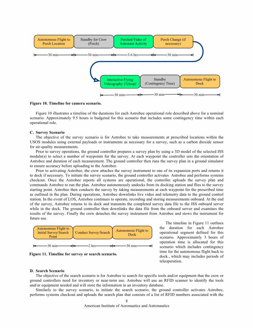
Figure 10 illustrates a timeline of the durations for each Astrobee operational role described above for a nominal scenario. Approximately 9.5 hours is budgeted for this scenario that includes some contingency time within each operational role.
C. Survey Scenario The objective of the survey scenario is for Astrobee to take measurements at prescribed locations within the
USOS modules using external payloads or instruments as necessary for a survey, such as a carbon dioxide sensor for air-quality measurements.
Prior to survey operations, the ground controller prepares a survey plan by using a 3D model of the selected ISS module(s) to select a number of waypoints for the survey. At each waypoint the controller sets the orientation of Astrobee and duration of each measurement. The ground controller then runs the survey plan in a ground simulator to ensure accuracy before uploading to the Astrobee.
Prior to activating Astrobee, the crew attaches the survey instrument to one of its expansion ports and returns it to dock if necessary. To initiate the survey scenario, the ground controller activates Astrobee and performs systems checkout. Once the Astrobee reports all systems are operational, the controller uploads the survey plan and commands Astrobee to run the plan. Astrobee autonomously undocks from its docking station and flies to the survey starting point. Astrobee then conducts the survey by taking measurements at each waypoint for the prescribed time as outlined in the plan. During operations, Astrobee downlinks live video and telemetry data to the ground control station. In the event of LOS, Astrobee continues to operate, recording and storing measurements onboard. At the end of the survey, Astrobee returns to its dock and transmits the completed survey data file to the ISS onboard server while in the dock. The ground controller then downlinks the data file from the onboard server and examines the results of the survey. Finally the crew detaches the survey instrument from Astrobee and stows the instrument for future use.
The timeline in Figure 11 outlines the duration for each Astrobee operational segment defined for this scenario. Approximately 3 hours of operation time is allocated for this scenario which includes contingency time for the autonomous flight back to dock., which may includes periods of teleoperation.
D. Search Scenario The objective of the search scenario is for Astrobee to search for specific tools and/or equipment that the crew or
ground controllers need for inventory or near-term use. Astrobee will use an RFID scanner to identify the tools and/or equipment needed and will store the information in an inventory database.
Similarly to the survey scenario, to initiate the search scenario, the ground controller activates Astrobee, performs systems checkout and uploads the search plan that consists of a list of RFID numbers associated with the
Perched Video of Astronaut Activity
Standby for Crew (Perch)
Autonomous Flight to Perch Location
Autonomous Flight to Dock
Standby(Contingency Time)
30 min
30 min
30 min
30 min 3-6 hrs
Perch Change (if necessary)
30 min
Interactive Flying Videography (Teleop)
30 min
Figure 10. Timeline for camera scenario.
Conduct Survey/SearchAutonomous Flight to Initial Survey/Search
Point
Autonomous Flight to Dock
30 min30 min 2 hrs
Figure 11. Timeline for survey or search scenario.

American Institute of Aeronautics and Astronautics
9
items to be identified and their corresponding suspected locations. Prior to running a search plan, the crew will attach the RFID scanner to Astrobee’s expansion port. Once Astrobee is ready, the ground controller will command it to run the search plan. Astrobee then undocks from its docking station and propels itself to the first location on the list. Astrobee scans the area with its RFID reader to find the item corresponding to that location. If the item is not there, Astrobee initiates an automated search pattern and continues to search until the item is found or the search is interrupted. Astrobee then moves to the next location on the list and repeats the search until all the items on the list are identified. During these operations, Astrobee is continuously downlinking live video and telemetry except during LOS. In addition, after each item is found, Astrobee downlinks the RFID and location information to the ground controller while storing all data onboard. Once all the items are found, Astrobee returns to dock where the crew will remove and stow its RFID scanner. Astrobee also downloads the search data file through the hard-wired connection at dock to the onboard server for future use.
E. Multiple Free-Flyer Operation Ground controllers will be able to operate more than one free-flyer at a time to: (1) perform multiple scenarios
separately at the same time; or (2) perform one scenario with more than one free-flyer at the same time. An example of the first case includes using one free-flyer to operate as a mobile camera platform in a specified module while commanding a second free-flyer to run a survey plan in another module. For this case, two ground stations will be needed to control two free-flyers simultaneously.
For the second case, an example scenario is guest science research on formation flight of two free-flyers. This scenario can be performed with a single ground station. The operator will separately command each free-flyer to enter guest science mode, and will then command the first free-flyer to start the guest science procedure. Any coordination between the two free-flyers, such as relaying the procedure start to the second free-flyer, will be implemented in the software provided by the guest scientist. The Astrobee platform will not provide any built-in multi-robot coordination, other than the capability to send messages between free-flyers via WiFi.
In general, the ground rules for operating more than one free-flyer at a time include: • Only one ground or crew station can control one free-flyer at a time. • The ground controller will be able to switch control from one free-flyer to another with consent of the
other ground controller or crew. • The free-flyer will only listen to commands from one controller who has accessed control of it. • The free-flyers will use obstacle avoidance to ensure they do not collide with each other. • Any ground controller or crew can command a free-flyer to emergency stop at any time.
F. Operational Contingencies There are a number of unplanned events that may occur at any time during operation that will limit or
temporarily terminate nominal operation of Astrobee. Some examples of these unplanned events include communication outages, propulsion failures, software or hardware malfunctions, navigation errors, unplanned obstacles or crew in its path, etc. Operational contingencies will be put in place in the flight software to address these unplanned events. There will also be various operational modes programmed in the flight software to easily switch to different levels of functionality depending on the severity of the unplanned event. The following are a few examples of operational contingencies.
In the event Astrobee encounters an unexpected obstacle(s) or crew in its pre-programmed path, Astrobee will come to a full stop, alert the ground of its halted position and wait for the ground controller to manually tele-operate the Astrobee around the obstacle, upload new waypoints for the Astrobee to navigate itself around the obstacle, or, in the case of crew, wait for crew to leave the planned path, then resume the original plan.
To avoid low-battery levels, Astrobee will constantly check its battery consumption. Once the battery falls below a certain threshold, Astrobee will alert ground controllers and will autonomously return itself to its dock to recharge. While at the dock, Astrobee will download all its data. Once the batteries are fully recharged, the Astrobee will notify ground controllers and wait for its next command. Typical full battery charges will take from 8 to 12 hours. In the interest of time, ground controllers may request the crew to manually swap out batteries on the Astrobee, rather than wait for them to charge at the dock.
For typical LOS outages, Astrobee will continue its nominal operations. The ground station GUI will indicate that it is not receiving telemetry data. After acquisition of signal, Astrobee will resume its downlink of live video and telemetry. If Astrobee experiences a significant drop out of WiFi connectivity, it will autonomously return itself to its dock where it can communicate to the ground over a hard-wired communications line. Once in the dock, Astrobee will wait for its next command from the ground.

American Institute of Aeronautics and Astronautics
10
For hardware or software failures, Astrobee will halt its operations and disable its propulsion, articulation and active sensing. The ground station GUI will provide a report of its hardware or software failure. The ground controller will troubleshoot the problem and take action to fix the problem. This action may include communicating to the crew and requesting that the crew manually re-dock Astrobee for full data download and analysis. Once the problem is fixed, the ground controller will reload and re-start its plan.
V. Key Challenges
A. Safety Many of the challenges faced by the Astrobee development team stem from operation onboard the Internation
Space Station, in particular, from operating in close proximity to astronauts and critical systems on the ISS. The team must strike a delicate balance between meeting performance requirements and developing an inherently safe system. Performance characteristics such as velocity and acceleration determine the forces imparted during collisions and may be addressed by minimizing mass and/or adding compliance. The Astrobee project carries a risk that because of safety concerns, Astrobee may not be certified by ISS for autonomous operations. If that becomes the case, it would greatly lessen the usefulness of the system.
B. Infrastructure-Free Navigation Astrobee is attempting to provide useful free-flyer capabilities without undue burden to the ISS system. This
most affects Astrobee’s navigation system design. We would like to create a system that requires installation of little or no infrastructure, generally in the form of beacons or cooperative markings. To this end, we are developing a visual navigation system that uses “natural” features of the ISS interior. Limited size and mass bound the amount of power available onboard for all functions, including computing. While advances in mobile computing have created small, powerful processors in recent years, there are still computational limitations for low-power embedded systems. Those constraints create a challenge to developing a robust, high-performance vision system.
C. Other Challenges As stated above, many of the challenges faced by the Astrobee development team are due to deployment
onboard the ISS. ISS levies many requirements on payloads in such areas as safety, human factors, launch loads, etc. For example, loud payloads on the ISS are limited in when and how long they are allowed to operate. The Astrobee propulsion team is challenged with developing a fan-based propulsion system with low enough noise characteristics to allow long duration usage.
If these and other challenges can be overcome, the Astrobee system will provide a new zero-g research platform and operational tool for the ISS that can improve the efficiency of current operations on the station and also inform NASA mission designs for future human exploration.
Acknowledgments We would like to thank the ISS Payloads Office, the JSC Flight Operations Directorate, ISS Avionics and
Software, the Advanced Exploration Systems program, and the SPHERES engineering team for their collaboration. The NASA Game Changing Development Program (Space Technology Mission Directorate) and ISS SPHERES Facility (Human Exploration and Operations Mission Directorate) provided funding for this work.
References
1 Fong, T., J. Rochlis Zumbado, N. Currie, A. Mishkin, and D. L. Akin, “Space telerobotics: unique challenges to human-robot collaboration in space,” Reviews of Human Factors and Ergonomics Society 9, 2014.
2 Russell, J. F., D. M. Klaus, and T. J. Mosher, "Applying Analysis of International Space Station Crew-Time Utilization to Mission Design", Journal of Spacecraft and Rockets, Vol. 43, No. 1 (2006), pp. 130-136.
3 Dorais, G.A., Y. Gawdiak, “The personal satellite assistant: an internal spacecraft autonomous mobile monitor,” IEEE Aerospace Conference, Vol. 1, IEEE, New York, 2003. DOI 10.1109/AERO.2003.1235064
4 Fong, T., et al., “The Human Exploration Telerobotics Project,” Global Space Exploration Conference, GLEX-2012.01.2.4x12180, International Astronautical Federation, Washington D.C., May, 2012.
5 “Reference guide to the International Space Station. -- Assembly complete ed.,” NASA NP-2010-09-682-HQ, 2010.